transportation.ky.gov Design Manu… · HD-702 01/06 Page 1 of 12 Chapter GEOMETRIC DESIGN...
28
HD-701 01/06 Page 1 of 1 Chapter GEOMETRIC DESIGN GUIDELINES Subject Introduction INTENT OF USE: This chapter includes geometric design guidelines that the Transportation Cabinet commonly uses. Unless otherwise stated, these guidelines are not intended to be mandatory. Instead, they are to provide guidance in safety, operation efficiency, convenience, and environmental quality. The American Association of State Highway and Transportation Officials (AASHTO)’s A Policy on Geometric Design of Highways and Streets and engineering judgment are to be used in the design process. This chapter is not to supersede the application of sound engineering principles by experienced design professionals. An emphasis on the involvement of the public and local communities in our decision-making process has increased. Situations that require increased flexibility in the design process will arise. Goals of the local community, such as environmental quality, aesthetics, and historic preservation, as well as goals of the Cabinet, need to be addressed. This document is not intended to address those unusual cases where one-lane facilities are considered. All criteria developed for those cases are to be considered as design exceptions and documented accordingly. CHAPTER TOPICS: The pages of this chapter contain information on: Primary design elements General design considerations Design exception process Design guidance for truck-climbing lanes and emergency escape ramps Kentucky “Common Geometric Practices” sheets and some example typical sections that may be used for reference during the design process (Exhibits 700-01 through 700-07)
-
Upload
truongthien -
Category
Documents
-
view
213 -
download
0
Transcript of transportation.ky.gov Design Manu… · HD-702 01/06 Page 1 of 12 Chapter GEOMETRIC DESIGN...
HD-701
01/06 Page 1 of 1
Chapter
GEOMETRIC DESIGN GUIDELINES
Subject
Introduction
INTENT OF USE: This chapter includes geometric design guidelines that the Transportation
Cabinet commonly uses. Unless otherwise stated, these guidelines are not intended to be mandatory. Instead, they are to provide guidance in safety, operation efficiency, convenience, and environmental quality. The American Association of State Highway and Transportation Officials (AASHTO)’s A Policy on Geometric Design of Highways and Streets and engineering judgment are to be used in the design process. This chapter is not to supersede the application of sound engineering principles by experienced design professionals.
An emphasis on the involvement of the public and local communities in
our decision-making process has increased. Situations that require increased flexibility in the design process will arise. Goals of the local community, such as environmental quality, aesthetics, and historic preservation, as well as goals of the Cabinet, need to be addressed.
This document is not intended to address those unusual cases where
one-lane facilities are considered. All criteria developed for those cases are to be considered as design exceptions and documented accordingly.
CHAPTER TOPICS: The pages of this chapter contain information on:
Primary design elements General design considerations Design exception process Design guidance for truck-climbing lanes and emergency escape
ramps Kentucky “Common Geometric Practices” sheets and some example
typical sections that may be used for reference during the design process (Exhibits 700-01 through 700-07)
HD-702
01/06 Page 1 of 12
Chapter
GEOMETRIC DESIGN GUIDELINES
Subject
Primary Design Elements
OVERVIEW: Discussed are several elements typically used in highway design,
including sight distance, horizontal alignment, vertical alignment, and cross-section. Each of these elements is important in the development of a highway design project and is further explained in the American Association of State Highway and Transportation Officials (AASHTO)’s A Policy on Geometric Design of Highways and Streets.
SIGHT DISTANCE: Sight distance is the length of highway that is visible ahead of the driver. In
highway design, there are four types of sight distance. Chapter 3 of A Policy on Geometric Design of Highways and Streets shows methods for computing these four distances:
Stopping Sight Distance: This is the distance required for a vehicle
traveling at or near the design speed to stop safely. It is the sum of two components: brake reaction time and braking distance. In computing and measuring stopping sight distance, the height of the driver’s eye is estimated to be 3.5 feet and the object height 2 feet.
Decision Sight Distance: There are cases when stopping sight
distance is not sufficient for the driver to avoid unforeseen or unusual occurrences. Typical examples of such occurrences are lane drops, areas of high traffic concentration, and traffic control devices. Under these circumstances, it is recommended that the designer consider decision sight distance. This is the distance required for the driver to detect an unexpected or unusual occurrence, recognize it as a hazard, and initiate and complete a maneuver that will allow the driver to safely and efficiently avoid the hazard. Decision sight distance is based on the same criteria of driver’s eye height and object height as stopping sight distance.
Passing Sight Distance: This is the distance required for a vehicle to
safely and successfully pass another vehicle, typically on a two-lane highway. Adequate horizontal and vertical passing sight distances are to be provided frequently. For computing and measuring passing sight distance, the height of the driver’s eye is estimated to be 3.5 feet; and the object height, which is based on average vehicle height, is also 3.5 feet.
CONT.
GEOMETRIC DESIGN GUIDELINES—Primary Design Elements HD-702
01/06 Page 2 of 12
SIGHT DISTANCE (cont.): Another definition of passing sight distance relates to the level of service
and design capacity concepts. Reference to the Highway Capacity Manual (HCM—Chapter 8) may be made for a complete discussion of passing sight distance.
Intersection Sight Distance: This type of sight distance is explored
in Chapter HD-900 of this manual. HORIZONTAL ALIGNMENT: Several components comprise the horizontal alignment design of a
highway, including tangents, circular curves, and, in many cases, spirals. Safety, existing conditions, environmental considerations, economics, and highway classifications influence the horizontal alignment.
CIRCULAR HORIZONTAL CURVES: Circular curves enable a change in direction of the roadway. The minimum
radius of a curve used for a given design speed is shown in Chapter 3 of A Policy on Geometric Design of Highways and Streets. The laws of mechanics that govern vehicle operation on curves, such as friction factors, speed, and the amount of superelevation, help to establish this minimum. Although the minimum radius is allowable, the designer is to strive to exceed it.
If compound curves are used on the main line, the radius of the flatter curve
is not to be more than 1.5 times greater than the radius of the adjacent sharper curve. It is preferable to avoid compound curves. For interchange ramp design, Chapter HD-900’s discussion of intersections is helpful.
Horizontal curves in the same direction separated only by a short tangent
(“broken-back” curves) and horizontal curves in the opposite direction separated only by a short tangent (reverse curves) should be avoided. Generally, it is preferable to use flatter curves connected by transition curves.
SPIRAL TRANSITION CURVES: On highways with design speed of 45 mph or greater, a motor vehicle does
not follow a path that is parallel to the center line of the road when traveling from a tangent section into a horizontal curve, or vice versa. This steering change cannot be adjusted instantly. Therefore, to make this transition from tangent to curve as smoothly as possible, it is recommended to use spiral curves when superelevation rates are 3 percent or greater. A spiral curve is a curve with a variable radius. As discussed in Superelevation (on the following page), the minimum length of runoff (L) values shown in Chapter 3 of A Policy on Geometric Design of Highways and Streets can be used to determine the minimum length of spiral for the transition curve. The lengths can be rounded up to even lengths that facilitate simpler calculations.
CONT.

GEOMETRIC DESIGN GUIDELINES—Primary Design Elements HD-702
01/06 Page 3 of 12
SPIRAL TRANSITION CURVES (cont.): Advantages of using spiral curves are that they:
Provide a natural path for drivers and minimize encroachment on adjoining traffic lanes
Provide a place to transition superelevation runoff Facilitate pavement widening through a curve Enhance the appearance of a highway
Chapter HD-904, "Interchanges," of this manual discusses interchange
ramp design. SUPERELEVATION: Maximum rates of superelevation for use on roadways are controlled by the
following factors:
Climate conditions (snow and ice occurrences) Terrain (flat, rolling, or mountainous) Urban or rural facilities Amount of slow-moving traffic
In general, a maximum rate of 8 percent is to be used on rural roadways due to Kentucky’s snow and ice frequencies. A maximum rate between 4 and 6 percent is recommended for use in urban areas, especially on low-speed, high-volume facilities. Superelevation tables in Chapter 3 of A Policy on Geometric Design of Highways and Streets determine the amount of superelevation to use for a given design speed and radius of curvature. Ultimately, the project engineer and the project team are to decide on a project-by-project basis which values will best suit the conditions of the facility.
When spirals are utilized, the superelevation runoff length (L) is to be the
same as the length of spiral. If spirals are not used, the minimum runoff lengths are shown in Chapter 3 of A Policy on Geometric Design of Highways and Streets. The transitions between the tangent section and the curve are to be divided as follows: Locate 2/3 of L on the tangent section, and extend 1/3 of L onto the horizontal curve. The point of curvature (P.C.) will be the control for this situation and will apply to both ends of the curve.
Once the spiral runoff length (L) is determined, the tangent runout can be
calculated. The runout (R) is the transition from a normal crown section to a section in which the outside lane(s) are rotated to a flat section. The formula for this transition length is:
R = Lc e
R = Runout length L = Length of spiral or length of runoff c = Normal rate of pavement crown (commonly 2 percent) e = Superelevation rate
CONT.
GEOMETRIC DESIGN GUIDELINES—Primary Design Elements HD-702
01/06 Page 4 of 12
SUPERELEVATION (cont.): Once the roadway is transitioned to this flat section, the template is
rotated to full superelevation utilizing the runoff (L) as the transition length. Note: The inside lane(s) do not begin to rotate until the outside lane(s) exceed the normal cross-slope of the inside lane(s). At this point both inside and outside lanes rotate together to full superelevation.
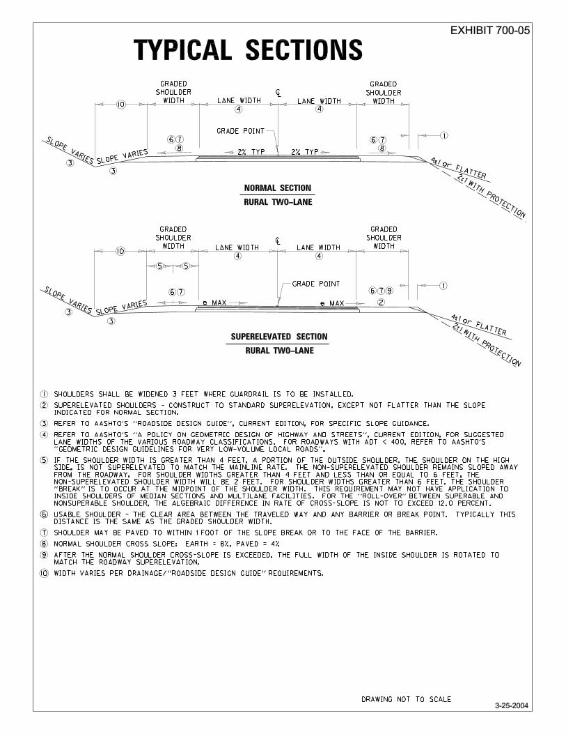
After the normal shoulder cross-slope is exceeded, the full width of the
inside shoulder is rotated to match the roadway superelevation.
For shoulder widths less than or equal to four feet, the full width of the outside shoulder is rotated to match the roadway superelevation.
If the shoulder width is greater than four feet, a portion of the outside
shoulder (the shoulder on the high side) is not superelevated to match the main line rate. The nonsuperelevated shoulder remains sloped away from the roadway.
♦ For shoulder widths greater than four feet and less than or equal to
six feet, the nonsuperelevated shoulder width will be two feet.
♦ For shoulder widths greater than six feet, the shoulder “break” is to occur at the midpoint of the shoulder width. This requirement may not apply to inside shoulders of median sections and multilane facilities.
For the “roll-over” between superable and nonsuperable shoulder, the algebraic difference in rate of cross-slope is not to exceed 12 percent.
The accepted method of attaining superelevation may be found by referring to Standard Drawings RGS-001 and RGS-002.
Truck-climbing lanes and auxiliary lanes are to be superelevated at the
same rate as the adjacent through lanes.
Written approval is to be obtained from the Director, Division of Structural Design, and the Director, Division of Highway Design, before developing plans for an alignment that requires a bridge superelevation rate greater than 6 percent.
PAVEMENT WIDENING ON CURVES: Offtracking is common to all vehicle types. When traversing a horizontal
curve, the rear wheels of a motor vehicle track inside the front wheels, thereby making it difficult for a driver to hold the vehicle in the center of the lane. These problems become more pronounced when lane widths are narrow and curves are sharp.
A common practice to help offset these conditions is to widen pavement on
horizontal curves. Since widening is costly and little is gained from a small amount of widening, a minimum of two feet is to be used.
CONT.
GEOMETRIC DESIGN GUIDELINES—Primary Design Elements HD-702
01/06 Page 5 of 12
PAVEMENT WIDENING ON CURVES (cont.): Standard Drawing RGS-001 and Chapter 3 of A Policy on Geometric
Design of Highways and Streets is to be used to determine the amount of widening for a particular radius of a curve. When spiral transition curves are used, the widening between the inside and outside edges of pavement is to be divided equally. The widening is to transition from zero at the tangent to spiral (T.S.) to full widening at the spiral to curve (S.C.).
When spiral transition curves are not used, all the widening is to be done on
the inside edge of pavement. The widening is to transition from zero at the beginning of the tangent runoff (L) to full widening at the point of full superelevation. Transition ends are to avoid an angular break at the edge of pavement.
SIGHT DISTANCE ON HORIZONTAL CURVES: The sight distance on a horizontal curve is measured along the center line
of the inside lane of the curve. In some cases, objects such as cut slopes, vegetation, or buildings obstruct the sight distance. When designing the horizontal alignment, the designer is to check into obtaining adequate sight distance on horizontal curves. In some instances, additional right of way may be required.
For horizontal curves, both passing sight distance and stopping sight
distance are to be considered. Passing sight distance is recommended for consideration only on tangents and very flat curves. Sight distance restrictions on sharper curves make this consideration prohibitive. Sight distance for horizontal curves is to be coordinated with the sight distance for vertical curves (see page 7).
An additional subject to consider in roadway design is intersection sight
distance for roads with at-grade intersections. Chapter HD-902, "At-Grade Intersections," and A Policy on Geometric Design of Highways and Streets provide insight.
VERTICAL ALIGNMENT: The terrain of the traversed land influences the design of the roadway.
Terrain is generally classified into three categories: level, rolling, and mountainous. Like horizontal alignment, vertical alignment consists of tangent sections and curves.
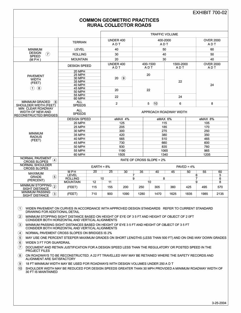
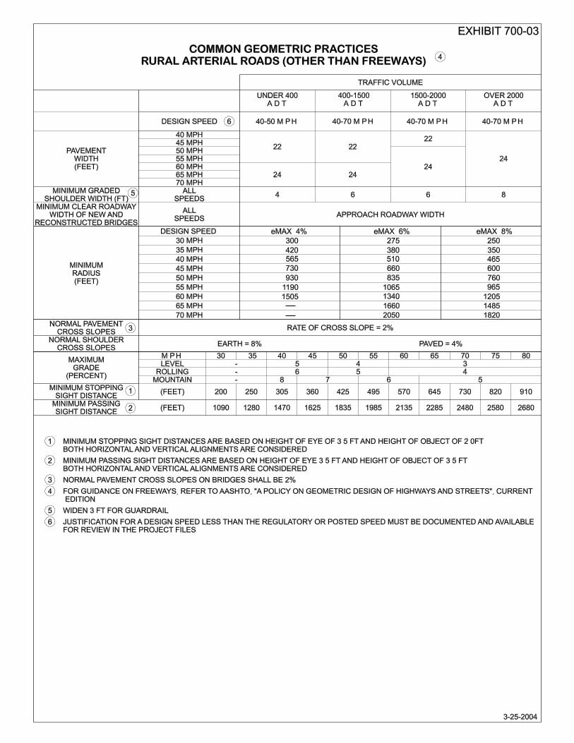
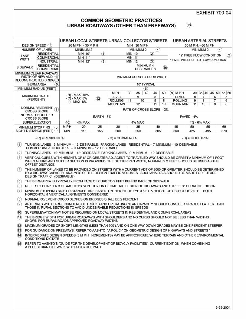
GRADES: The design speed and type of terrain establish the suggested maximum
grades. The suggested maximum grades are shown in Exhibits 700-01, 700-02, 700-03, and 700-04 of this manual. Also considered in the design process are the types of vehicles expected on the roadway. The effect of grade is far more pronounced on truck speeds than on the speeds of passenger cars. In addition to the grade percentage, the length of grade is also very important. Chapter 3 of A Policy on Geometric Design of Highways and Streets shows how to determine critical lengths of grade.
CONT.
GEOMETRIC DESIGN GUIDELINES—Primary Design Elements HD-702
01/06 Page 6 of 12
GRADES (cont.): A Policy on Geometric Design of Highways and Streets suggests a maximum grade of 5 percent for a design speed of 70 miles per hour and 7 to 12 percent for a design speed of 30 miles per hour. The maximum design grade is not to be considered the desirable grade to achieve on a roadway. Where feasible, it is recommended that grades be less than the maximum allowable. However, grades less than 500 feet in length and one-way downgrades may be approximately 1 percent steeper than the maximum. Such a grade may be increased to 2 percent if on a low-volume rural highway. Steeper grades may also be used where extremely high construction costs would be encountered to produce flatter grades. Care is to be taken when increasing grade in rural areas because the increase may introduce the need for truck-climbing lanes. The project team is to discuss the use of grades steeper than the maximum, and the project manager is to document the use in the Preliminary Line and Grade Report and in the Design Executive Summary.
It is necessary to maintain a minimum grade in order to provide adequate
drainage. Level grades may be used on uncurbed, nonsuperelevated roadways as long as there is an adequate crown. It is recommended that curbed roadways maintain a minimum grade of 0.50 percent. A grade of 0.30 percent may be considered if there is a high-type, adequately crowned pavement.
The maximum suggested grades for entrances are shown in Standard
Drawing RPM-110. VERTICAL CURVES: The introduction of vertical curves affects the transition from one rate of
grade to another and usually consists of a parabolic curve. Vertical curves are either the crest or sag type, depending on the positive or negative slopes of the intersecting grades. Any standard route-surveying textbooks for details on the method of calculating vertical curves may be referenced.
A common means to determine the minimum length of curve needed for
various design speeds is K, the rate of curvature. K is determined by dividing the length of vertical curve (L) by the algebraic difference (A) in grades (L/A). K is the horizontal distance required to effect a 1 percent change in gradient.
After K is found, the minimum length of vertical curve (L) can be calculated
by using information in Chapter 3 of A Policy on Geometric Design of Highways and Streets. Suggested lengths of vertical curve for a given design speed are based on sight distance for crest vertical curves and on headlight sight distance for sag vertical curves.
In addition to sight distance, the designer is to also consider appearance
and riding comfort when selecting a length of vertical curve. Long vertical curves give a more pleasing appearance and provide a smoother ride than short vertical curves.
CONT.
GEOMETRIC DESIGN GUIDELINES—Primary Design Elements HD-702
01/06 Page 7 of 12
SIGHT DISTANCE ON VERTICAL CURVES: The design of both crest and sag vertical curves are dependent on stopping
sight distance calculations:
Crest Vertical Curves: The stopping sight distance is based on the height of eye of 3.5 feet and the height of object of 2 feet.
Sag Vertical Curves: The stopping sight distance is based on a 2-foot
headlight height and a 1-degree angle of light spread upward from the headlight beam.
The stopping sight distance values for various design speeds listed in Chapter 3 of A Policy on Geometric Design of Highways and Streets are to be minimum values. Generally, it is not practical to design crest vertical curves to provide for passing sight distance because required distances are 7 to 10 times longer than on a tangent or a sag condition. Chapter 3 of A Policy on Geometric Design of Highways and Streets details stopping sight distance design controls.
CROSS-SECTIONS: To determine the typical cross-section for a given highway, designers are
to use four basic design controls:
Functional classification Area (rural or urban) Volume of traffic Design speed
The context of the project (Environmental, Right of Way, Utilities, Pedestrians, and other considerations) may affect selection of the typical cross-sections.
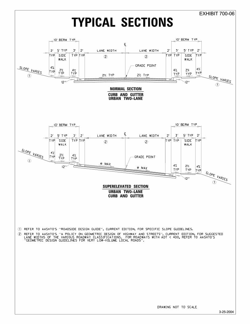
The Common Geometric Practices (Exhibits 700-01 through 700-04 of this
manual) with the approved geometric design are to be used to determine the typical cross-section. Exhibits 700-05 through 700-07 show example typical sections. Cross-section items include the following:
Pavement slope and width Shoulder width and slope Curb placement Typical earth slopes in cuts and fills
Traveled ways located in tangent sections usually have a crown or high
point located in the center and a cross-slope down to the edges of pavement. Divided multilane highways may be crowned separately as a two-lane highway, or they may have a unidirectional cross-slope across the entire width of traveled way. The rate of cross-slope is important. Steep slopes minimize ponding of water, but they may be uncomfortable to the driver. It is recommended that the cross-slope range from 1.5 to 2 percent.
CONT.
GEOMETRIC DESIGN GUIDELINES—Primary Design Elements HD-702
01/06 Page 8 of 12
CROSS-SECTIONS (cont.): Roadway lane widths affect the comfort and safety of driving. Generally,
12-foot lanes are suggested. Chapter 4 of A Policy on Geometric Design of Highways and Streets provides additional information.
The shoulder of a roadway is adjacent to the traveled way and is used for
stopped vehicles and lateral support of sub-base, base, and surface courses. Shoulders can also be used to:
Avoid potential crashes Improve sight distance Provide driver comfort Improve highway capacity Provide lateral clearance for signs and guardrail Provide space for pedestrians and bicyclists
Shoulders range from 2-foot earth shoulders on minor rural roads to 12-foot paved shoulders on major roadways. Contrary to the definitions of shoulder widths in A Policy on Geometric Design of Highways and Streets, Kentucky’s definitions are as follows:
Graded or Full Shoulder: The distance from the edge of travel lane to
slope break
Usable Shoulder: The clear area between the traveled way and any barrier or break point. Typically this distance is the same as that of the graded or full shoulder when barriers are not present.
Paved Shoulder: The width of shoulder paving, which may be
constructed up to any portion of the shoulder within one foot of the slope break or to the face of the barrier
Note: Unless otherwise specified, references to shoulder in this manual shall mean “graded or full shoulder.”
The minimum inside full shoulder width is six feet on four-lane divided
highways. For six or more lanes, the inside shoulder shall be the same as that determined for the outside shoulder. Any exceptions are to be documented in the Design Executive Summary (see Chapter HD-704, "Design Exception Process," for more information).
The chart on the following page suggests some minimum paved-shoulder
widths:
CONT.

GEOMETRIC DESIGN GUIDELINES—Primary Design Elements HD-702
01/06 Page 9 of 12
CROSS-SECTIONS (cont.):
Minimum Paving Width Requirements for Shoulders*
TRAFFIC SHOULDER PARAMETERS ADT PAVED
(Feet) EARTH (Feet)
AGGREGATE (Feet) TOTAL WIDTH (Feet)
RURAL LOCAL - RURAL COLLECTOR1 0 - 400 -- 2 -- 2
400 - 15002 -- 5 -- 53
1500 - 2000 2 4 -- 6 OVER 2000 4 4 -- 8
2 - LANE ARTERIALS (OTHER THAN FREEWAYS)1 0 - 400 4 0 - 2 0 - 2 6
400 - 2000 6 0 - 2 0 - 2 8 OVER 2000 8 0 - 2 0 - 2 10
4 - LANE ARTERIALS - FREEWAYS - INTERSTATES Outside
Shoulders 10 0 - 2 0 - 2 12
Inside Shoulders 4 0 - 2 0 - 2 6 6 - LANE ARTERIALS - FREEWAYS - INTERSTATES
Outside Shoulders
10 0 - 2 0 - 2 12
Inside Shoulders 10 0 - 2 0 - 2 12 *Variations to shoulder paving may be considered for context sensitive solutions and should be documented in the Design Executive Summary. 1For shoulders less than 12 feet, widen 3 feet for guardrail. 2For roads in mountainous terrain with design volume of 400 to 600 vehicles/day, use 18-ft traveled way width and 2-ft shoulders. 3Shoulder width on collectors may be reduced for design speeds greater than 30 mph as long as a minimum roadway width of 30 ft. is maintained.
Curbs are often used on low-speed urban highways. On such highways it is preferable to offset the curb one to two feet from the edge of traveled way. If curbs are used on high-speed rural highways, they are to be located outside the edge of the shoulder. It is recommended that vertical curbs utilized along the outside edge of the shoulder of a high-speed facility be of the mountable type and be limited to a four-inch vertical height. This design is especially important if the curb is being used in conjunction with other types of traffic barriers.
CONT.
GEOMETRIC DESIGN GUIDELINES—Primary Design Elements HD-702
01/06 Page 10 of 12
CROSS-SECTIONS (cont.): Ditches and embankment slopes are not geometric design elements and
therefore are not subject to the Design Exception Process. Roadside ditches are to be evaluated on the basis of their ability to function hydraulically. The choices of fill slopes and ditch configurations are always to take into account their effects on roadside safety. Generally, fills lower than 10 feet should be 4:1, and fills higher than 10 feet should be 2:1 with adequate protection. The AASHTO Roadside Design Guide defines 4:1 slopes as recoverable, 3:1 slopes as traversable, and steeper than 3:1 slopes as hazardous. Chapter HD-800, Roadside Design, and AASHTO’s Roadside Design Guide provide additional information.
The project manager in concert with the project team is to determine the level of geotechnical investigation required. Typically this varies from advisory to full-scale geotechnical analysis. Generally, when embankments are to be constructed over existing ground slopes of 15 percent or greater, embankment foundation benches are to be constructed in the existing slopes. The Transportation Cabinet’s Standard Drawings Manual provides specific details. Ditch benching and overburden and/or weathered zone benching details are outlined in the Transportation Cabinet’s Geotechnical Manual.
MEDIANS: A median is the portion of a highway separating opposing directions of
the traveled way. The median width is the dimension between the edges of the traveled way and includes any left shoulders. It has been demonstrated that there is a benefit derived from any type of traffic separation on multilane facilities, whether it be raised or flush. Wider medians are desirable at rural, unsignalized intersections; however, at urban/suburban signalized intersections, medians wider than 60 feet may lead to inefficient signal operation. Further detailed information on median design can be found in Chapter 4 of A Policy on Geometric Design of Highways and Streets.
Below are some of the various functions of medians:
Separate opposing traffic flow Provide a recovery area for out-of-control vehicles Provide a stopping area in case of emergencies Minimize headlight glare from oncoming vehicles Provide width for future turn lanes Provide storage for left-turning or crossing vehicles from an approach
road Open green space (urban areas) Refuge for pedestrians (urban areas) Control of left-turning/U-turning movements
CONT.

GEOMETRIC DESIGN GUIDELINES—Primary Design Elements HD-702
01/06 Page 11 of 12
TYPES OF MEDIANS: There are three types of medians: depressed, flush, and raised. The
context of the project (environmental, maintenance, right of way, utilities, pedestrians, cost, and other considerations) will affect selection of the median type. Described below are the different types of medians:
Depressed Medians: Depressed medians provide traffic separation,
accommodate roadway drainage, facilitate maintenance activities, and provide storage for snow and ice removed from the roadway. Depressed medians are generally utilized in areas where there is sufficient right of way available, where the need for constructed median crossovers are relatively few, and where the roadway has either partially or fully controlled access. A depressed median can also be used with partial control facilities where access is fairly limited or is restricted to right turns in and out with the exception of specific median crossover locations. The median side-slopes and any drainage structures located within the median area should follow the recommendations of AASHTO’s Roadside Design Guide. Depressed medians should have a minimum width of 40 feet.
Flush Medians: Flush medians provide traffic separation,
accommodate traffic movement, facilitate maintenance activities, and provide storage for snow and ice removed from the roadway. Flush medians are generally utilized on urban facilities with widths varying from 4 feet minimum to 16 feet maximum. Common practice has been to use a 12-foot to 14-foot flush median when utilized as a two-way left-turn lane (TWLTL). The median should be crowned or depressed for drainage. Flush medians should be delineated according to guidance found in the Manual on Uniform Traffic Control Devices (MUTCD).
It is to be noted that flush medians and TWLTLs have different
functional characteristics and are to be addressed accordingly. The TWLTL operation may be appropriate where the speed on the roadway is relatively low (45 mph or less) and there are no heavy concentrations of left-turning traffic. TWLTLs are to be striped according to guidance found in the MUTCD.
Raised Medians: There are three types of raised medians:
♦ Mountable Medians: Mountable medians may be utilized to
address channelization, clear zone, aesthetics, or drainage issues. Standard Drawings RPM-011, RPM-012, and RPM-015 show specific details of mountable medians.
CONT.
GEOMETRIC DESIGN GUIDELINES—Primary Design Elements HD-702
01/06 Page 12 of 12
TYPES OF MEDIANS (cont.):
♦ Nonmountable Medians: Nonmountable medians (barrier medians) typically may be utilized for traffic separation, pedestrian havens, channelization, or access management. Barrier medians typically use curbs to separate the median from the traveled way. Standard Drawing RPM-010 shows details. When used in close proximity to traffic, barrier medians may create safety concerns at higher speeds and are to be considered in context with other project design elements and costs.
♦ Median Barriers: Median barriers typically may be used in high-
speed applications to address traffic separation and channelization. Median barriers are detailed in Standard Drawings RBM-001, RBM-003, RBM-006, RBM-050, and RBM-053. AASHTO’s Roadside Design Guide shows use and placement of median barriers.
CROSSOVERS: Emergency/maintenance crossovers are breaks in the median to allow
emergency and maintenance traffic to cross. To avoid extreme adverse travel for emergency, law-enforcement, and maintenance vehicles, emergency/maintenance crossovers on rural freeways are normally provided where interchange spacing exceeds five miles. Care should be taken in the design of these to ensure they do not present an undue hazard to the through traffic. The “Intersection” chapter of A Policy on Geometric Design of Highways and Streets gives design details.
BRIDGE WIDTHS: The usable shoulder width is to be maintained across bridges. Any
exceptions are to be documented in the Design Executive Summary. The minimum width of a bridge on a two-lane bidirectional roadway is 22 feet. For roads with ADT<400, AASHTO's Geometric Design Guidelines for Very Low-Volume Local Roads (ADT≤ 400) is to be consulted.
A six-foot minimum inside shoulder is required across bridges on four-lane
divided highways. This requirement means that the inside shoulder on the roadway is to be widened near the bridge end to accommodate barriers (see Standard Drawing RBB-002). The width of the outside shoulder on the bridge is to be the same as the distance from the roadway shoulder to the face of the barrier.
The Transportation Cabinet’s Bridge Design Manual discusses other bridge
geometric design issues.

HD-703
01/06 Page 1 of 4
Chapter
GEOMETRIC DESIGN GUIDELINES
Subject
General Design Considerations
OVERVIEW: Certain factors are important in the design process. The criteria differ for
each functional classification of roadway. The suggested design criteria for each classification can be found in the American Association of State Highway and Transportation Officials (AASHTO)’s A Policy on Geometric Design of Highways and Streets.
DESIGN CONSIDERATIONS: For any highway project the design controls and design criteria establish
the minimum values to use for the primary elements of a particular highway. Design controls and design criteria normally considered in the design of a highway are:
Functional classification
Area (urban or rural)
Volume of traffic (DHV [design hourly volume] and ADT [average daily
traffic])
Percentage of trucks
Design speed
Topography (flat, rolling, or mountainous terrain)
Level of service (for more information see Chapter 2 in AASHTO’s A Policy on Geometric Design of Highways and Streets.)
Environment
Other modes of transportation (bicycles, pedestrians, etc.)
Special considerations such as the length of the project, the
condition of roads in the vicinity of the project, and the likelihood of adjoining segments being improved in the foreseeable future
CONT.
GEOMETRIC DESIGN GUIDELINES—General Design Considerations HD-703
01/06 Page 2 of 4
DESIGN CONSIDERATIONS (cont.): In the early stages of a project, a TC 61-9 form, Design Executive Summary
(DES) (Exhibit 00), is approved by the Director, Division of Highway Design. This form specifies the values used for the design criteria. Chapter HD-203, "Conceptual Design," provides for more specific information on DES submittal. There are other factors to consider during the design process. The following are suggestions that promote good design practices:
Do not design horizontal and vertical alignments independent of each other. The coordination of these elements is to begin early in the design process.
Create alignments consistent with the existing topography and
preserving property and community values.
A flowing line that conforms generally to the natural topography is preferable to one with long tangent sections that cuts through the terrain.
Attempt to utilize flat curves with radii greater than the suggested
minimum values, using the suggested minimum values for the most difficult conditions.
An alignment is to be as consistent as possible. If possible, avoid
introducing sharp curves at the end of long tangents. Also, if possible, avoid sudden shifts from flat curvature to sharp curvature.
Vertical curves that fall within the limits of horizontal curves, or vice
versa, generally result in a more pleasant roadway facility.
Create horizontal and vertical alignments to be as straight and flat as practical at intersections due to the need to provide appropriate sight distance along both intersecting roadways.
Do not automatically utilize the minimum suggested values for design.
ROADWAY CLASSIFICATION: The “functional classification” of a roadway is the grouping together of
roadways by the type of service they provide based upon land use and type of traffic being generated along a corridor. This classification has been developed as a means of communication within the Transportation industry. The determination of a facility’s functional classification is one of the first steps in the design process. It should be noted that over time the functional classification of a highway can change, depending on the intensity of development and the type of traffic being generated by the development of the corridor. The three basic types of functional classifications are:
CONT.

GEOMETRIC DESIGN GUIDELINES—General Design Considerations HD-703
01/06 Page 3 of 4
ROADWAY CLASSIFICATION (cont.):
Rural/Urban Arterials: Arterials provide a high degree of mobility for the longer trip length. Therefore, they may provide a high operating speed and level of service. Since access to abutting property is not their major function, some degree of access control is desirable to enhance mobility. Arterials are discussed in Chapter 7 of AASHTO's A Policy on Geometric Design of Highways and Streets.
Freeways: A freeway is normally classified as a principal arterial that has unique geometric criteria. Freeways are discussed in Chapter 8 of AASHTO's A Policy on Geometric Design of Highways and Streets.
Rural/Urban Collectors: Collectors serve a dual function in
accommodating the shorter trip and feeding the arterials. They must provide some degree of mobility and serve abutting property. Thus, an intermediate design speed and level of service are appropriate. Collectors are discussed in Chapter 6 of AASHTO's A Policy on Geometric Design of Highways and Streets.
Rural/Urban Local Roads and Streets: Local roads and streets have
relatively short trip lengths, and because property access is their main function, there is limited need for mobility or high operating speeds. The use of a lower design speed and level of service reflects this function. Local roads and streets are discussed in Chapter 5 of AASHTO's A Policy on Geometric Design of Highways and Streets.
The geometric design of very-low-volume local roads presents a unique
challenge: The very low traffic volumes and reduced frequency of crashes make designs normally applied on higher-volume roads less cost-effective. The guidance by AASHTO's Geometric Design Guidelines for Very Low-Volume Local Roads (ADT≤ 400) addresses the unique needs of such roads and the geometric designs appropriate to meet those needs. These guidelines may be used for roadways with ADT ≤ 400.
Note: Chapter 1 of AASHTO's A Policy on Geometric Design of Highways
and Streets gives a more detailed discussion of roadway classifications.
DESIGN SPEED: Design speed is a selected speed used to determine the various geometric design features of the roadway. It is the highest continuous speed at which individual vehicles can travel with safety upon a highway when weather conditions are favorable, traffic density is low, and the geometric design features of the highway are the governing conditions for safe speed.
CONT.

GEOMETRIC DESIGN GUIDELINES—General Design Considerations HD-703
01/06 Page 4 of 4
DESIGN SPEED (cont.): The design speed should be consistent with the speed the driver expects. It
should be logical for the topography, adjacent land use, and type of highway. The design speed should equal or exceed the posted or regulatory speed limit of the completed facility. For a further discussion of the philosophy of design speed, see AASHTO's A Policy on Geometric Design of Highways and Streets.
For federal aid projects, the selected design speed must equal or exceed the posted or regulatory speed limit of the completed facility unless design exceptions are processed.
Document justification for the design speeds in the Design Executive Summary (see HD-704). This justification should consider all project conditions including maximum service and safety benefits for the dollar invested, compatibility with adjacent sections of unimproved roadway, and the probable time before reconstruction of the section due to increased traffic demands or changed conditions. When requesting exceptions, include a discussion of safety requirements and the related accident data associated with the site.
When design speeds are less than the regulatory or posted speed, erect
mitigation measures such as advisory speed plates and warning signs.

HD-704
01/06 Page 1 of 2
Chapter
GEOMETRIC DESIGN GUIDELINES
Subject
Design Exception Process
USE OF DESIGN EXCEPTION PROCESS: Although the range of values suggested in this design manual and in
AASHTO's A Policy on Geometric Design of Highways and Streets provides a flexible range of design features, there will be situations in which the use of the minimum suggested criteria would result in unacceptable right-of-way, utility, environmental, and historical impacts and project costs. For these situations, the design exception process is to be utilized to determine and document the reasons or justifications for the exceptions.
CONTROLLING CRITERIA: There are 13 controlling criteria specified by the Federal Highway
Administration (FHWA) for National Highway System (NHS) routes. These criteria are to be used on all projects as a basis for design exceptions. The criteria are as follows:
Design speed Lane width Shoulder width Bridge width Structural capacity Horizontal alignment Vertical alignment Grade Stopping sight distance Cross slope Superelevation Vertical clearance Horizontal clearance (not including clear zone)
Exhibits 700-01 through 700-04 represent Kentucky Common Geometric Practices. The values in these exhibits are not to be construed as a basis for determining design exceptions. The designer is to refer to AASHTO's A Policy on Geometric Design of Highways and Streets and AASHTO's Geometric Design Guidelines for Very Low-Volume Local Roads (ADT≤ 400).
CONT.
GEOMETRIC DESIGN GUIDELINES—Design Exception Process HD-704
01/06 Page 2 of 2
EXCEPTION PROCESS: The project team is to identify exceptions to criteria early in the design
process. Documentation of recommendations and discussions is to be included in meeting or inspection reports. The team is to document design exceptions in the Design Executive Summary (DES), with a detailed written discussion of the sound engineering reasoning and justification for the exceptions, when submitting for approval. FHWA must approve exceptions for interstate projects. Chapter 203, "Conceptual Design," of this manual provides more specific information on DES submittal and approval procedures.
HD-705
01/06 Page 1 of 2
Chapter
GEOMETRIC DESIGN GUIDELINES
Subject
Truck-Climbing Lanes & Emergency Escape Ramps
TRUCK-CLIMBING LANES: Besides being limited to passing sections, heavily loaded vehicles on
sufficiently long upgrades adversely affect the safety and operating speed of traffic on two-lane highways. Truck-climbing lanes are commonly included in original construction or added on existing highways as safety- and capacity-improvement projects. AASHTO's A Policy on Geometric Design of Highways and Streets and the Highway Capacity Manual contain additional information on truck-climbing lanes.
WARRANTS FOR TRUCK-CLIMBING LANES: To justify a climbing lane, the designer is to:
Upgrade traffic flow rate more than 200 vehicles per hour
Upgrade truck flow rate more than 20 vehicles per hour
Meet one of the following conditions:
♦ Expect a 10-mph or greater speed reduction for a typical heavy
truck ♦ Ensure that a level of service E or F exists on the grade ♦ Experience a reduction of two or more levels of service when
moving from the approach segment to the grade
However, safety considerations alone may justify the addition of a climbing lane regardless of grade or traffic volumes.
The project team is to consider justification for climbing lanes when exceeding the critical length of grade based on a highway capacity analysis.
CONT.
GEOMETRIC DESIGN GUIDELINES— Truck-Climbing Lanes & Emergency Escape Ramps HD-705
01/06 Page 2 of 2
SHOULDERS ON TRUCK-CLIMBING LANES: Desirably, the shoulder on the outer edge of a climbing lane is to be as
wide as the shoulder on the normal two-lane section, particularly where there is bicycle traffic. When adding the climbing lane to an existing highway and conditions dictate, a usable shoulder of a four-foot width or greater is acceptable.
EMERGENCY ESCAPE RAMPS: On long descending grades, an emergency escape ramp is to be
considered. The selection of type is dependent on the existing conditions. Further discussion on selection and methods of design is in AASHTO'S A Policy on Geometric Design of Highways and Streets.
Many factors are to be considered in selecting specific sites for an escape
ramp on new or existing facilities. These factors include:
Topography Length and percent of grade Potential speed Economics Environmental impacts Crash experience/data