Independ-2500 - Flowtech
13
EN - Instruction Manual Independ-2500 Petrol Generator Art.nr. 44.173.4
Transcript of Independ-2500 - Flowtech
EN - Instruction Manual
Independ-2500 Petrol Generator
Art.nr. 44.173.4

2
EN
CONTENTS
I - Safety Information. . . . . . . . . . . . . . . . . . . . . . . . . . . . 28
II - Description. . . . . . . . . . . . . . . . . . . . . . . . . . . . . . . 29
III - Check before using. . . . . . . . . . . . . . . . . . . . . . . . . . . 31
IV - Operation . . . . . . . . . . . . . . . . . . . . . . . . . . . . . . . 32
V - Periodic maintenance . . . . . . . . . . . . . . . . . . . . . . . . 34
VI - Problem Solving. . . . . . . . . . . . . . . . . . . . . . . . . . . 37
VII - Storage. . . . . . . . . . . . . . . . . . . . . . . . . . . . . . . . 37
VIII - Technical Specifications . . . . . . . . . . . . . . . . . . . . . . . 38
IX - Circuit Diagram . . . . . . . . . . . . . . . . . . . . . . . . . . . .51

3
Warning!
Read this entire instruction booklet carefully in its entirety before using the device, and keep
it to refer to when necessary.
I - SAFETY INFORMATION
1 – Exhaust fumes are poisonous
Never run the engine in a closed space; it could result in unconsciousness and death
in a very short time. Only use the engine outside or in a well-ventilated space.
2 – Fuel is highly flammable and poisonous
Always switch the engine off when filling the tank.
Never fill the tank while smoking or in the vicinity of an open flame.
Take care not to spill fuel on the engine or exhaust when filling the tank.
If you swallow fuel, breath in fuel vapour or get fuel in your eyes see a doctor
immediately. If you spill fuel in your house or on your clothes immediately clean it
with soap and water and change your clothes.
Ensure that the device is kept upright when in operation and during transport. If it tilts
then fuel can leak from the carburettor or the fuel tank.
3 – Engine and exhaust can be hot
Place the device in a location that cannot be accessed unnoticed by pedestrians or
children.
Ensure that no flammable materials are in the vicinity of the exhaust when operating
the device.
The device must be at least 1 metre from
buildings or other obstacles to prevent the
engine from overheating.
Do not operate the device if it is covered in
dust.
Only lift the device by the handle.
Place the device on a level surface, so that
it can dissipate heat freely.
4 – Prevent electrical shock Do not use the engine in rain or snow.
Never touch the device with wet hands as
there is danger of an electrical shock.
Ensure that the generator is earthed.
N.B.! Use a earth lead of sufficient capacity. Diameter: 0.12mm / ampere. E.g.: 10 Ampere – 1.2mm.
5 – Warning regarding connections Do not connect the generator to the mains.
Do not connect the generator in parallel to
another generator.

4
II - DESCRIPTION
1. Economy switch
2. Engine switch
3. Fuel tank
4. Spark plug
5. Exhaust
6. Carry handle
7. Choke lever
8. Indicator light AC (alternating current)
9. Overload warning light
10. Oil warning light
11. AC alternating current socket
12. DC direct current socket
13. Earth point
14. Fuel filter
15. Tank cap
16. Pull cord starter
17. Fuel cock
18. Oil filter cap
19. Air filter cover

5
II-1 – Oil warning system If the oil level drops below the lowest level then the engine will automatically stop. You must top up the oil and restart the engine.
II-2 – Engine switch The engine switch controls the ignition system ON – the ignition system is switched on, the engine can be started.
STOP – the ignition system is switched off, the engine will not run.
II-3 – Economy switch If the Economy switch is switched ON then the motor speed is adjusted to the connected load. The result is better combustion and less noise.
II-4 – The Direct Current overload protection The DC direct current overload protection (the red light at the direct current socket) automatically switches off the engine if the load exceeds the maximum capacity. Attention! Reduce the load to below the indicated maximum capacity if the overload protection causes the engine to cut out.
II-5 - Tank cap ventilation knob The tank cap is fitted with a ventilation knob. Prior to starting the engine the ventilation knob must be rotated once anti-clockwise from the closed position. This prevents the fuel causing a vacuum in the tank and not flowing properly. Tighten the ventilation knob again when switching off the engine by turning it clockwise. The ventilation knob must always be closed during transport and storage.
II-6 – Fuel cock When the fuel cock is opened (ON) then the fuel supply to the carburettor is opened. By closing the fuel cock (OFF) the fuel supply is cut off.
OPEN CLOSED

6
III - INSPECTION BEFORE USE
N.B.!
- If using the generator for the first time the tank must have at least 2 litres of fuel.
- The generator must always be inspected prior to being used
III-1 – Check the fuel level
Ensure that there is enough fuel in the tank
If there is too little fuel then fill it with lead free petrol; ensure that the filter is always in
the tank opening when filling, see fig.
The content of the fuel tank is 5.1 litres.
Warning!
Never fill the tank when the engine is running or still
hot.
Close the fuel cock before filling the tank.
Keep the fuel free of dust, dirt, water or other
materials/objects.
Do not fill the tank past the filter; when the fuel heats
up it expands.
Close the tank cap properly after filling.
Wipe up any spilled fuel before starting the engine.
Keep the generator and fuel away from open flames.
III-1 – Check the oil level
Check that the oil level is filled to maximum in the oil
reservoir. Top up oil if necessary.
Remove the cap with the dip stick and check the oil
level
If the oil level is below the minimum level, top it up to
the maximum level. Do not screw the cap on when
checking the oil level.
Change the oil if it is dirty.
Contents oil reservoir: 0.9 litres
Recommended oil: API Service “SJ” or above, see
table.
III-3 – Earthing
Equip the generator with a properly connected, properly
functioning earth wire.

7
IV - OPERATION
N.B.!
- the generator is transported without oil. If you fail to fill the oil reservoir the generator will
not start.
- Ensure that the generator is completely level when filling up with oil. Tilting could result
in overfilling and damage the engine.
IV-1 – Starting the engine
N.B.!
- Do not connect any electrical equipment before starting the engine
- Switch the Economy switch to the OFF position
a) Open the ventilator knob on the tank cap (See II-
5)
b) Open the fuel cock (See II-6)
c) Switch the engine switch to the ON position
d) Set the choke lever to the position (CHOKE).
The latter is not necessary if the engine is still
hot.
e) Pull the starter cord out slowly until you feel
resistance. That is the ‘point of compression’.
Let the cord run back in to the starting position
and now pull hard. At the same time hold the
generator firmly in position by the handle to
prevent it falling over when pulling. Do not pull the
cord out all the way. After starting let the starter
cord run back to its starting position without
releasing the handle. Repeat if necessary, if the
engine doesn't start the first time.
f) Let the engine run warm
g) Push the choke lever back to its operating position RUN.
h) Allow the generator a few minutes to run warm without a load.
IV-2 – Connecting up electrical equipment
A – AC Alternating current use
i) Check whether the AC indicator light shows that the voltage level is correct
j) Set the Economy switch to the ON position
k) Ensure that all equipment to be connected is switched off prior to connecting
l) Plug the plug(s) from the equipment into the sockets on the generator.
Warning!
Be sure that the equipment being connected is switched off
Ensure that the total connected capacity does not exceed the maximum
Be sure that the required and supplied voltage is the same.
The Economy switch must be switched off if you use electrical equipment that requires
high peak current, like a compressor or a submersible pump.
8
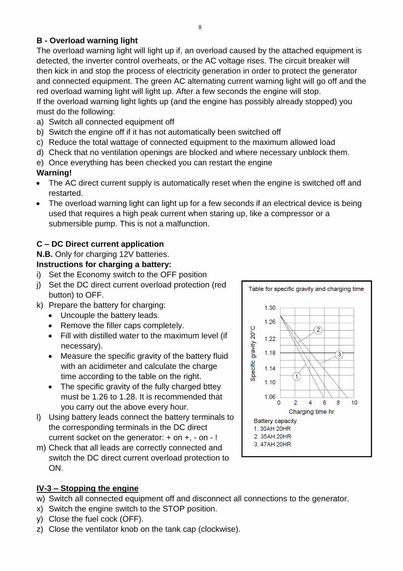
B - Overload warning light
The overload warning light will light up if, an overload caused by the attached equipment is
detected, the inverter control overheats, or the AC voltage rises. The circuit breaker will
then kick in and stop the process of electricity generation in order to protect the generator
and connected equipment. The green AC alternating current warning light will go off and the
red overload warning light will light up. After a few seconds the engine will stop.
If the overload warning light lights up (and the engine has possibly already stopped) you
must do the following:
a) Switch all connected equipment off
b) Switch the engine off if it has not automatically been switched off
c) Reduce the total wattage of connected equipment to the maximum allowed load
d) Check that no ventilation openings are blocked and where necessary unblock them.
e) Once everything has been checked you can restart the engine
Warning!
The AC direct current supply is automatically reset when the engine is switched off and
restarted.
The overload warning light can light up for a few seconds if an electrical device is being
used that requires a high peak current when staring up, like a compressor or a
submersible pump. This is not a malfunction.
C – DC Direct current application
N.B. Only for charging 12V batteries.
Instructions for charging a battery:
i) Set the Economy switch to the OFF position
j) Set the DC direct current overload protection (red
button) to OFF.
k) Prepare the battery for charging:
Uncouple the battery leads.
Remove the filler caps completely.
Fill with distilled water to the maximum level (if
necessary).
Measure the specific gravity of the battery fluid
with an acidimeter and calculate the charge
time according to the table on the right.
The specific gravity of the fully charged bttey
must be 1.26 to 1.28. It is recommended that
you carry out the above every hour.
l) Using battery leads connect the battery terminals to
the corresponding terminals in the DC direct
current socket on the generator: + on +, - on - !
m) Check that all leads are correctly connected and
switch the DC direct current overload protection to
ON.
IV-3 – Stopping the engine
w) Switch all connected equipment off and disconnect all connections to the generator.
x) Switch the engine switch to the STOP position.
y) Close the fuel cock (OFF).
z) Close the ventilator knob on the tank cap (clockwise).

9
V PERIODIC MAINTENANCE
V-1 – Maintenance card
Regular maintenance is the most important condition for correct and safe operation.
Section: Activity After
each use
Every
month
or 20
hrs
Every 3
months
or 50
hrs
Every 6
months
or 100
hrs
Every 12
months
or 300
hrs
Spark plug
Check condition, adjust gap
if necessary, replace if
necessary
●
Engine oil Check the oil level ●
Change the oil ●
Oil filter Clean the oil filter ●
Air filter Clean the air filter and
replace if necessary ●
Fuel filter Clean the fuel filter and
replace if necessary ●
Choke Check that it's working ●
Valve clearance
Check and adjust if
necessary when the engine
is cold
●
Fuel line Check for kinks or damage
and replace if necessary. ●
Exhaust system
Check for leaks Seal
properly or replace gasket. ●
Check exhaust cover and
clean or replace ●
Carburettor Check that the choke is
working ●
Cooling system Check the ventilator for
damage ●
Starter system Check that the pull-cord
starter is working ●
Stationary revs Check and adjust if
necessary. ●
Couplings and
connections
Check and attach correctly
if necessary ●
Sump bleeding
Check vent hose for kinks
or damage and replace if
necessary
●
Generator Check that the indicator
lights are working ●
V-2 – Changing engine oil

10
a) Place the device on a flat, level surface and start and
warm up the engine for a few minutes. Stop the engine
and turn off the fuel cock (OFF). Close the ventilator
knob on the tank cap (clockwise).
b) Loosen the screw and remove the side panel, see fig.
c) Remove the cap from the oil filter.
d) Place a collector tray under the generator and tilt it so
that all oil runs out
e) Place the generator back on the flat, level surface
f) Pour the new engine oil into the reservoir until the
maximum level is reached
g) Put the oil filter cap back on
h) Replace the cover and screw it tight
Recommended engine oil: API Service “SJ” or above
Warning!
Ensure that no foreign materials get into the carter.
Do not top up oil in a generator that is not horizontal; that
could result in overfilling and damage to the engine.
Clean the oil filter every 100 operating hours.
V-3 – Air filter
It is very important that the air filter is kept in good condition.
Pollution due to badly installed, incorrectly maintained or
wrong air filter will cause premature damage and wear to
the engine. Therefore always keep the filter clean.
a) Loosen the screw and remove the side panel.
b) Remove the cover from the air filter and the
filter.
c) Wash the filter in a mild soapy solution and
allow it to dry properly.
d) Drop a little oil on the filter and squeeze it so
that the oil spreads and excess oil runs off
(squeeze don't wring!). The filter must be moist
but not dripping.
e) Reinstall the filter.
f) Replace the cover and attach the side panel
again.
Warning! Never run the generator without air filter!
This will cause extreme wear of the piston and/or
filter.

11
V-4 – Cleaning and adjusting the spark plug a) Loosen the screw and remove the top panel.b) Remove the spark plug cap and remove the spark
plug.c) Clean off any deposits, check for discolouration
(standard colour is brown) and check the distancebetween the poles. This should be between 0.6 en0.7 mm. Adjust if necessary. If the spark plugappears worn then replace it with the same type ofspark plug: CR7HS(NGK).
d) Reinstall the spark plug.e) Replace the top panel.
V-5 – Fuel tank filter a) Remove the tank cap and the filter.b) Wash the filter in mild soapy water, if it is damaged
then it must be replaced.c) Rub the filter dry and replace it.Warning! Close the tank cap again properly.
V-6 – Exhaust cover Warning! � Engine and exhaust are extremely hot after running! Do not touch them with bare hands
or clothes. Allow the device to cool down before inspection or repairs! a) Remove the back panel.b) Remove the exhaust cover.c) Use the flat edge of a screwdriver to pry the spark
suppressor out of the exhaust.d) Remove carbon deposits from the exhaust cover and
spark suppressor.e) Reinstall the
spark suppressorand exhaustcover correctly.

12
VI – SOLVING PROBLEMS
VI-1 – The engine will not start
Fuel is not being transported to the carburettor
- The fuel tank is empty - put in fuel
- There is fuel in the tank – turn the fuel cock and the ventilation knob to ON
- The fuel line is blocked – clean it
- The carburettor is blocked – clean it
The engine has insufficient oil
- Add oil
Problems with the ignition system, insufficient spark
- The spark plug is dirty or damp – clean and/or dry it
- Problems with the ignition system – consult your dealer
VI-2 – The generator is not generating electricity
The safety facility AC is set to OFF
- Stop the engine and re-start it
The safety facility AC is set to OFF
- Press it to reset it.
VII - Storage.
If being stored for a longer period your generator requires a number of preventative
measures to protect it.
VII-1 – Drain off the fuel
a) Remove the tank cap and allow the fuel to drain from the tank
b) Remove the side panel and allow the fuel to also drain from the carburettor
VII-2 – Engine
a) Remove the spark plug and pour a teaspoon of motor oil (SAE 10W30 or 20W40) into
the opening. Reinstall the spark plug.
b) Allow the engine to turn over a few times by pulling gently on the recoil starter (without
ignition).
c) Pull the starter cord out slowly until you feel resistance.
d) Then stop pulling
e) Clean the outside of the generator and use a rust retarder
f) Store the generator in a dry, well-ventilated area and cover it.
g) The generator must stay upright.
13
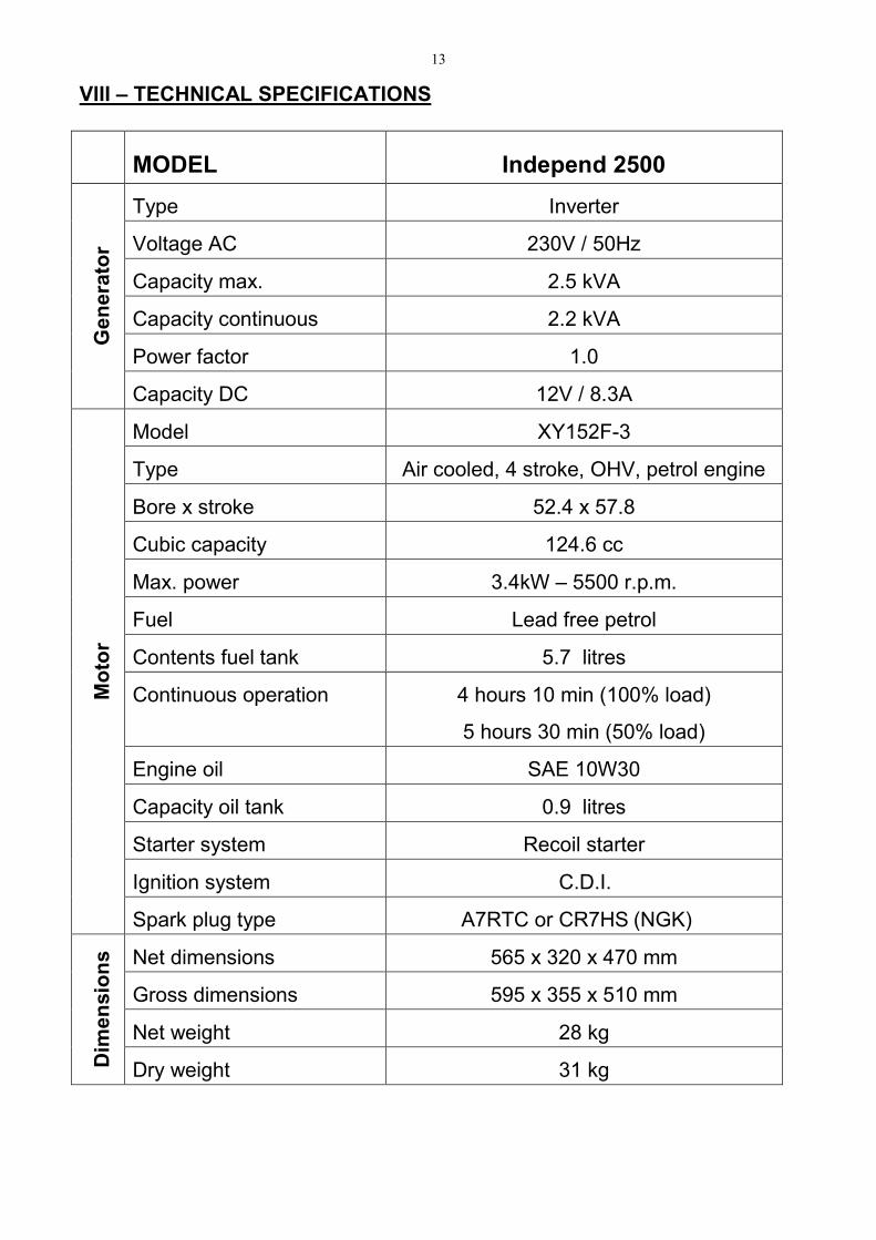
VIII – TECHNICAL SPECIFICATIONS
MODEL Independ 2500
rotare
neG
Type Inverter
Voltage AC 230V / 50Hz
Capacity max. 2.5 kVA
Capacity continuous 2.2 kVA
Power factor 1.0
Capacity DC 12V / 8.3A
Mo
tor
Model XY152F-3
Type Air cooled, 4 stroke, OHV, petrol engine
Bore x stroke 52.4 x 57.8
Cubic capacity 124.6 cc
Max. power 3.4kW – 5500 r.p.m.
Fuel Lead free petrol
Contents fuel tank 5.7 litres
Continuous operation 4 hours 10 min (100% load)
5 hours 30 min (50% load)
Engine oil SAE 10W30
Capacity oil tank 0.9 litres
Starter system Recoil starter
Ignition system C.D.I.
Spark plug type A7RTC or CR7HS (NGK)
sn
oisne
miD
th
gieW
&
Net dimensions 565 x 320 x 470 mm
Gross dimensions 595 x 355 x 510 mm
Net weight 28 kg
Dry weight 31 kg


![Independ%c3%a ancia dos estados unidos[1][1]](https://static.fdocuments.net/doc/165x107/55cb43f5bb61ebb6668b474c/independc3a-ancia-dos-estados-unidos11-55cc11cff2f9e.jpg)