
Performance Management Centers for Excellence Report Year Four

Incorporation of a High Performance, Four-Cylinder, Four-Stroke Motorcycle Engine into a Snowmobile Application
Gregory A. Davis, Nick S. Dahlheimer, David A. Meyer, Aaron S. Messenger, James R. Johnson, Bernhard P. Bettig
Michigan Technological University
Copyright © 2005 SAE International
ABSTRACT
For the 2003 and 2004 SAE Clean Snowmobile Challenges, the successful implementation of a clean, quiet, high-performance four-stroke motorcycle engine into an existing snowmobile chassis was achieved. For the 2005 Challenge, a new motor and chassis were selected to continue the development of a four cylinder, four stroke powered snowmobile. The snowmobile is as powerful as today’s production performance models, as nimble as production touring sleds, easy to start, and environmentally friendly. This report describes the conversion process in detail with actual dynamometer, emissions, noise, and field test data, and also provides analysis of the development processes and data. The vehicle meets the proposed 2012 EPA snowmobile emissions regulations and is significantly quieter than a stock snowmobile.
INTRODUCTION
In response to the pollution concern of current snowmobile use in pristine areas, the Clean Snowmobile Challenge (CSC) was created. The CSC is a national, collegiate design competition administered by the Society of Automotive Engineers (SAE). The purpose of the competition is to challenge universities and their students to address the rising concern of pollution, both noise and emissions, from snowmobiles. Michigan Technological University has diligently strived to increase team awareness, and as a result, has accepted nearly 30 new members. The team is composed of undergraduate and graduate students with majors in Mechanical Engineering, Mechanical Engineering Technology, Electrical Engineering, Electrical Engineering Technology, Biology, Scientific and Technical Communication, and Business. All of these students unify as one team to compete and excel in the 2005 Clean Snowmobile Challenge.
The team’s primary goals for the 2004 CSC were to design and produce a snowmobile with exhaust emissions below the proposed 2012 EPA snowmobile
regulations and a noise level lower than that of today’s quietest 4-stroke snowmobiles. These goals had to be achieved while maintaining reasonable cost, comparable performance, and expected durability. For the 2005 CSC, the team decided to continue their work with 4-cylinder, 4-stroke engines because they felt that a great deal of improvement could be made over previous designs. In order to accomplish these improvements, the team started from “the ground up” by designing and building a completely new and innovative snowmobile, utilizing both positive and negative knowledge gained from previous designs. These goals can be found in Table 1. A comparison between the 2004 goals and the 2005 goals can also be made to observe the areas in which the team wanted to improve the snowmobile for the 2005 CSC.
Table 1: Michigan Tech CSC Goals
2004 Goal 2005 Goal
440cc two-stroke equivalent performance
600cc two-stroke equivalent performance
Emissions passing 2012 EPA Regulations
Emissions passing 2012 EPA Regulations as well as surpassing previous designs and entrants to the CSC
Noise output lower than that of quiet 4-stroke snowmobile (Arctic Cat 660 touring), 105 dBa
Noise output lower than that of any production snowmobile, 105 dBa
Easy maneuvering, navigating trails as easily as a manufacturer’s snowmobile at 64 km/hr
Easy maneuvering, rider comfort and ergonomics matching that of manufacturer’s snowmobiles
It is observed in Table 1 that the team attained every one of their goals with the 2004 snowmobile. For 2005,

the team felt that they could take their success to the next level by designing a snowmobile that would surpass the expectations of even those from years past in all areas of the CSC. While there is always room for improvement in existing designs, the team decided to start over for 2005. A different motor was selected and a chassis was chosen to accommodate the new power plant. The design of this new snowmobile focuses on all aspects of the CSC, and because of this, the team will exceed design parameters of years past and achieve each goal set for 2005.
This report discusses the design of Michigan Tech’s entry into the 2005 SAE Clean Snowmobile Challenge. All aspects of the design will be included as well as test results achieved by the team prior to the 2005 CSC. The design can be separated into four major categories: Performance, Emissions Control, Noise Control, and Consumer Acceptability.
BACKGROUND
Since the late 1960’s, most snowmobile manufacturers have utilized a two-stroke, spark-ignited engine as the primary power source. The two-stroke engine provides a large power output in a compact, lightweight, and cost effective design. The inherent disadvantage of the two-stroke engine is its poor control over the gas exchange process, as both the exhaust and intake valve are open, simultaneously allowing intake charge, consisting of air, fuel, and oil, to pass directly through the combustion chamber into the exhaust without being ignited. On average, 20-33 percent of the intake charge is allowed to pass through the exhaust port without being ignited [1]. Another disadvantage is the fact that oil and gasoline are mixed into the intake charge and oil is consumed by combustion. These downfalls lead to high output levels of hydrocarbon (HC) and carbon monoxide (CO) emissions [2].
In recent years manufactures have addressed these emission concerns and have incorporated innovative technology into 2-stroke engines. Such innovations include new intake processes, new injector styles, and the inclusion of Direct Injection. This involves injecting a precise amount of fuel into the combustion chamber in contrast to having "approximately" the correct amount of fuel being drawn in along with the air flow. Also, with direct injection, the fuel is better atomized than with standard 2-stroke engines, resulting in a cleaner and more complete burning of the fuel. On average, the fuel efficiency of direct-injection 2-stroke engines is 30 percent better than conventional engines [3].
High levels of emissions produced from two-stroke snowmobiles have caused concern among several key environmental groups. In 1997, several of these groups filed suit against the National Park Service, requiring them to conduct an Environmental Impact Study (EIS). This study was titled, “Winter Use Plans Final Environmental Impact Statement for Yellowstone and Grand Teton National Parks, and the John D.
Rockefeller Jr., Memorial Parkway” [4]. The EIS has been followed by proposed EPA emissions regulations for off-highway vehicles, including snowmobiles.
The EPA released regulations for snowmobile emissions in September of 2002 [5]. The three-phase reduction calls for a 30 percent reduction in emissions by 2006, a 50 percent reduction by 2010, and a 70 percent reduction by 2012. Table 2 outlines these regulations.
Table 2: EPA Snowmobile Emissions Regulations
Year of effectiveness
Maximum HC g/kW-hr
Maximum CO g/kW-hr
2006 100 275
2010 75 275
2012 75 200
STRATEGY OVERVIEW
Table 3 is a list of components and equipment used to meet the team goals of 600cc two-stroke equivalent performance, an acceleration run to 500 feet in less than 7 seconds, possession of a specific power of at least 25W/N, 2012 EPA Emissions Regulations, and a noise level less than 105 dBa utilizing the testing procedure as outlined in the rules for the 2005 Clean Snowmobile Challenge [6].
Table 3: Snowmobile Component Specifications
Component Description Chassis 2004 Polaris ProX 600
Engine Honda CBR 954cc RR, inline 4-cylinder, 4-stroke, dual overhead cam, spark-ignited, liquid cooled
Fuel System Honda Stock CBR954RR PGM-FI (Programmed Fuel Injection), Walbro Inline Fuel Pump
Intake System
Modified Honda CBR954RR Intake System, naturally aspirated
Exhaust System
Exhaust Headers: Stainless Steel, MTU Clean Snowmobile Designed and Fabricated 4-2-1 System, Thermal Barrier Coating Catalyst: 500cpsi TS Catalyst Muffler: MTU Clean Snowmobile Designed Muffler System
Drivetrain
Primary Drive: Micro Belmont Reactor Four Tower. Secondary Drive: TEAM Fast Reaction, Totally Encapsulated Roller Helix
Semi-Direct Drive System incorporating a FAST Inc. Gearbox, geared reduction of 2.1:1
Suspension
Front suspension: Polaris trailing arm with Fox FLOAT Shocks utilizing air springs Rear suspension: Polaris equipped with Ryde FX shocks having adjustable compression
Track 121” x 1.25” x 15” Camoplast Ripsaw Bump Track
The four design areas of performance, emissions control, noise control, and consumer acceptability will now be discussed in detail.
PERFORMANCE
In order for the Michigan Tech team to accomplish their performance strategy goals, team efforts were focused on three main topics. These include power adaptation from the engine to a Continuously Variable Transmission (CVT), incorporation of a semi-direct drive system, and packaging all components in such a manner that would allow the center of mass to be as low as possible while maintaining rider comfort.
POWER TRANSMISSION
When selecting a motor for the 2005 CSC, the team drew on their previous success by using Honda inline 4-cylinder, 4-stroke, spark ignited engines. In order for the team to achieve its goals for 2005, they selected a Honda CBR 954RR engine. This engine has a displacement of 954cc, is spark ignited, and naturally aspirated. The motor is rated at 114.8 kW (154 Hp) while maintaining nearly the same external dimensions as the previously used smaller displacement Honda CBR 600F4i engine. The larger displacement engine was chosen due to its high power and torque output which allows the motor to operate in a lower rpm range while exceeding the performance of the smaller displacement engine. This choice benefits the design in many ways, including the advantage of better fuel economy, lower emissions output, and lower noise output, while still achieving high performance capabilities.
In order to fully utilize the motorcycle engine, modifications had to be made to transmit power from the engine to the ground. These modifications include the Power Take Off (PTO) adapter and the semi-direct drive system.
PTO Adapter
Power had to be transferred from the motorcycle engine to the ground via the CVT system. This required the design of an output system enabling the mounting of the primary drive pulley.
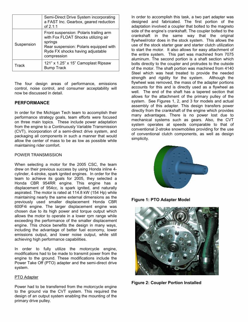
In order to accomplish this task, a two part adapter was designed and fabricated. The first portion of the adaptation involved a coupler that bolted to the magneto side of the engine’s crankshaft. The coupler bolted to the crankshaft in the same way that the original flywheel/rotor does in the stock system. This allows the use of the stock starter gear and starter clutch utilization to start the motor. It also allows for easy attachment of the entire system. This part was machined from 7075 aluminum. The second portion is a shaft section which bolts directly to the coupler and protrudes to the outside of the motor. The shaft portion was machined from 4140 Steel which was heat treated to provide the needed strength and rigidity for the system. Although the flywheel was removed, the mass of the adapter portions accounts for this and is directly used as a flywheel as well. The end of the shaft has a tapered section that allows for the attachment of the primary pulley of the system. See Figures 1, 2, and 3 for models and actual assembly of this adapter. This design transfers power directly from the crankshaft of the engine which provides many advantages. There is no power lost due to mechanical systems such as gears. Also, the CVT system operates at speeds comparable to that of conventional 2-stroke snowmobiles providing for the use of conventional clutch components, as well as design simplicity.
Figure 1: PTO Adapter Model
Figure 2: Coupler Portion Installed

Figure 3: Complete Adapter Assembly
As previously mentioned, the adapter is also used as a flywheel, thus reducing design complexity so that precision must be met while balancing the assembly. This was obtained using a Magna-Matic 7000 Series balancer which utilizes a free spinning shaft and gravity to allow for balancing of the part. This tool can be seen in Figure 4.
Figure 4: Magna-Matic Balancer
The system was designed for infinite life with a load of maximum belt force constantly applied to the end of the shaft and the torque applied by the engine. Pro/Engineer modeling was done for visualization and interference checking before machining the parts. Both portions were machined from billet using a Computer-Numerically Controlled (CNC) lathe and mill. The steel shaft portion was then heat treated to provide added strength and durability.
The completed analysis for the coupler/shaft assembly includes estimated life due to a fluctuation moment on the portion of the shaft extending out of the cover, as well as a Finite Element Analysis (FEA) of the complete assembly. For the fatigue calculations, infinite life was desired and a safety factor of 1.5 was built into the calculations and the minimum shaft diameter was solved for. The FEA analysis was done using the solid model and computer software. Loads assumed were a 400 lbf on the end of the shaft in the radial direction due to belt forces seen by the primary pulley, and a pure torsion force of 136 N-m due to the torque produced by the motor. These forces were assumed in light of the
previous design assumptions used on the CBR 600 motor adapter which is still in service with no evident signs of failure. The FEA results may be viewed in Figure 5.
Figure 5: FEA Results of Adapter
The second component involved in the transmission adaptation is a support cover which incorporates a bearing that supports the aforementioned shaft. The cover replaces the existing Honda alternator cover of the engine. First of all, this particular cover had to be designed to be load-bearing, primarily in a radial fashion with respect to the bearing; therefore, a structural analysis had to be preformed. Secondly, the cover had to interface with the existing bolt pattern and sealing surface on the Honda motor. In order to achieve this, precision measurements were made using a coordinate measuring machine (CMM). The coordinates were subsequently used to aid in the design of the part and to ensure accurate dimensional control upon manufacturing. Third, the cover had to allow adequate inner clearance for the shaft and coupler assembly. Fourth, the cover had to incorporate a seal to prevent oil from escaping the engine. Lastly, the cover had to be designed in such a fashion that we will be able to be machined. The new engine cover was modeled in I-DEAS using the CMM acquired coordinates. All of the constraints and requirements stated above were taken into consideration in the design of the cover. A photo of the design can be seen below in Figure 6. The cover, made from 6061-T6 Aluminum, was machined using a CNC horizontal mill.
Figure 6: Photo of Completed Support Cover

FEA was also used in order to validate the design. The main concern was assessing the structural integrity of the cover, so it was decided to use the Finite Element method, via IDEAS. For the FEA, the radial input load at the bearing surface was 3 kN (based on worst-possible-scenario loading conditions). This loading condition was a worst-possible-scenario condition, that is, the existing bearing just inside the support cover couples the entire moment caused by the belt tension. It was assumed that there would be no axial forces at any time during operation. The bolt holes were fixed (no displacement allowed), but rotation was permitted. FEA results can be seen in figure 7. Figure 7: FEA Results of Support Cover
FEA results for every component can be found below in Table 4. The values shown are Von Mises stresses and represent the average stresses on the component.
Table 4: Results of FEA Analysis
Setup Material Max
Stress (PSI)
Min. Stress (PSI)
Weight (Lb)
Safety Factor
Shaft Assembly
ASTM 4140 + AL7075
31300 (Steel) 0.65 6.7 2.08
Support Cover
AL6061 T6 352 0.00864 6.6 105
Semi-Direct Drive System
Due to the orientation of the engine, exhaust facing rearward, and the position of the crankshaft adapter, the primary pulley spins the opposite direction of that required to propel the snowmobile forward. For this reason a FAST Inc. gearbox was chosen. This gearbox utilizes a two gear mesh which reverses the direction of rotation in order to properly drive the snowmobile. The gearbox also provides a gear reduction of 2.1:1, thus offering an advantage in torque present to propel the snowmobile. A semi-direct drive system provided benefits in several other areas, including overall weight
reduction of the drive system, increased reliability through the elimination of the chain and sprockets (common failure components), compact packaging, and increased safety with the placement of the brake on the driveshaft. See Figure 9 for a picture of the complete system.
The primary clutch is an eight inch diameter Micro Belmont Reactor Four Tower. Common to that of the Polaris P-85, this clutch offers a wide operating range while still maintaining excellent tuning characteristics needed for clutching in an application such as the 2005 design. The Micro Belmont has a peak operating range of 14,000 revolutions per minute (RPM) which is much higher then a stock primary of around 9,000 RPM. The MTU design operating range is 10,000 RPM, thus justifying the need for the precision machined and balanced Micro Belmont. The Micro Belmont is tunable using four variables: weight profile, weight mass, pin mass, and spring stiffness. These factors will allow achievement of the peak operating range, cruising RPM, and the desired engagement RPM.
For the secondary clutch, a TEAM Industries Rapid Reaction with a 27.3 cm diameter was chosen. The TEAM secondary utilizes a dual roller mechanism coupled with progressive angle helixes to offer exceptional efficiency and quick back shifting capabilities. The small 30 cm clutch center to center distance, due to the low engine placement and gearbox location constraints of the chassis, provide for the use of a short, but standard, and readily available belt of 116.2 cm inches in length.
Clutching components, including primary springs, weights, and pins, were used during testing to tune the drive system. The system was required to operate between 3,000 and 10,000 RPM. A typical snowmobile drive system operates between 4,000 and 8,000 RPM. For this reason, several components were designed and manufactured in order to obtain the desired engagement up shift characteristics and full shift RPM. Optimized weight profiles were designed and utilized to obtain a well-balanced system. The setup of the Micro Belmont allowed use of the full RPM range with and engagement rpm of 3,000 and a peak of 9,500 RPM desired for competition. The appropriate back shifting was achieved with the TEAM secondary to allow an optimal cruising RPM of 5,000. This configuration allows for lower RPM, which causes improved fuel economy and decreased noise levels at cruising speeds, while still maintaining excellent acceleration and top speed.
With the incorporation of the gearbox, a driveshaft was also designed and fabricated. Splines were cut into the shaft at the gearbox end to mach the lower gear of the gearbox, and keyed at the other for the use of the brake rotor.
To prevent failure of the gearbox input shaft, a support arm was designed and fabricated. It was designed to support both clutches, eliminating the individual motion

of the clutches. This will ensure that the clutches align under all operating conditions and reduce the moment caused by the belt force on both the gearbox input shaft and the engine output shaft. This is a crucial part of the system due to the high forces seen by both shafts from the belt force of the high torque motor. The support was made from 6061-T6 aluminum with a bearing pressed into each end. See Figures 9 and 10 for pictures of the support and the FEA analysis performed to ensure that it would in fact provide the needed support to permanently affix both clutches. It greatly reduces forces on both shafts and also keeps the clutches perfectly aligned, thus greatly increasing efficiency of the overall system.
Figure 9: Semi-Direct Drive System
Figure 10: FEA of Clutch Support Arm
Braking For the redesigned drivetrain, the brake system was moved from its standard location on the jackshaft to the driveshaft where it is positioned opposite the secondary clutch. Moving the brake system to the driveshaft places weight lower in the chassis, improving the vehicle’s center of gravity. Due to the absence of the reduction found with a chaincase that affects conventional braking,
the brake location also provides greater control when slowing the sled. This brake location also offers the assurance of safety, giving the rider the ability to apply braking force at all times under all conditions, whereas the traditional chaincase brake does not. If a chain or gear failure occurs in the chaincase, the brake is rendered useless and the rider has no control over the speed of the snowmobile. Applying braking to the driveshaft eliminates these dangerous scenarios. The brake used in the 2005 design is a Wilwood caliper and rotor. The rotor has been machined to a diameter of 18.1 cm to reduce the drop in the belly pan to accommodate for rotor position. The caliper was then moved closer to the tunnel to maintain over 90 percent of the stock braking surface.
PACKAGING/MASS CENTERING
Modifications had to take place to make the engine fit into the chassis in a manner that least effected the handling of the chassis. These modifications include the exhaust/seat lift and remote oil filter assembly.
Exhaust System
The exhaust system used on the CBR954RR engine incorporated an exhaust valve in the headers that changed the collector phasing between cylinders. The utilization of this valve would not work in the 2005 design since the height of the exhaust needed to be minimized due to the limited clearance with under the gas tank exhaust routing. It was required to design a completely new exhaust to be fabricated. There were several constraints in the design. The stock length of the headers in the RPM ranges of 3,000 to 7,000 RPM was 85.09 cm to the first collector and 36.83 cm to the second collector. This resulted in an overall length of 121.9 cm from the head to the last collector. This put the last collector less than 30.48 cm away from the end of the tunnel, not allowing enough distance for overall fit with 30.48 cm needed for the catalyst and 30.48 cm for the muffler.
The design of the exhaust utilized Lotus Engine simulation software. A model of the engine was created, inputting all of the specific values for the engine such as bore, stroke, cylinder phase, cam lift, number of valves, valve area, and intake type. Using this model, simulations were run to find the optimum length of the primary and secondary header lengths. The simulation was setup allowing for a change of the primary and secondary pipes by 1.27 cm in variations between 1 and 63.5 cm for the primary, and a range of 2.54 to 63.5 cm for the secondary, keeping the maximum total length to 36 inches. Upon interpreting the simulation results and noting that the RPM range of 3000 to 7000 is of most importance in the CSC, the lengths of 53.34 cm for the primary and 38.1 cm for the secondary headers were chosen. See Figure 11 for the simulation model used.

Figure 11: Engine Simulation Model
Stainless steel was the material of choice for the construction of the exhaust. Given the high temperatures due to an optimally running engine and the closed space that the exhaust would be housed in, along with the cost, it removed the possibility of using Titanium for construction.
The welding was done using TiG construction for best penetration and appearance. Four flex pipes were installed in the headers to limit the amount of flexing and possible breaking of the exhaust due to the flexibility of the snowmobile chassis. After the construction was completed, the exhaust was thermal barrier coated, resulting in greater exhaust gas velocity and higher efficiency. Another reason for the coating was to reduce the amount of heat radiated from the headers to the gas tank. The coating was completed using White Lightning from Swain Tech. The TBC-EX coating is a 3-layer 0.381-0.508 mm thick permanent coating. The coating is pearl white in color and extremely durable. According to Swain Tech, it reduces radiant heat by more than 50 percent. Refer to Figure 12 for a photo of the exhaust system.
Figure 12: Exhaust System
To route the exhaust system to the rear of the snowmobile and still be able to drive the snowmobile in a comfortable riding position, a new seating area had to be constructed above the exhaust. A seat frame composed of C-channel aluminum and aluminum plating was placed below the seat. A Polaris ProX2 seat was hollowed out to provide more room for the exhaust. The Polaris seat provided a comfortable seating position as well as the ability to remove some of its material. The gas tank that best suited our design was one from a Yamaha Rx-1 snowmobile. The Yamaha gas tank has the bottom of the tank curved upward in the middle to provide room for the exhaust, which is also routed beneath the tank/seat on Yamaha’s snowmobile. Additionally, the gas tank is on a riser made of C-channel aluminum.
The new seating system allows for the exhaust to be routed below the rider and places the rider in a more aggressive riding position. The clearance underneath the seat also allows for the design of a larger muffler to be used for noise control.
Another main concern for the exhaust system was heat generation. Type-S Kaowool ceramic fiber insulation, one inch in thickness, was used between the exhaust area and the seat and gas tank. The seat and gas tank are underlined with a floor and tunnel heat shield which will reflect heat as well as reducing up to 50 percent of unwanted noise. The combination of these materials provides heat insulation needed to protect the components of the snowmobile along with the rider. Two electric fans, similar to those used in computers, are also incorporated into the system. The fans are positioned at the front of the gas tank blowing in, and in the rear blowing up and out of the exhaust area. This allows for better circulation of unwanted hot air under the gas tank and rider.
Intake
Because the airbox is mounted above the head in it's motorcycle application, the intake runners are more vertical than would be ideal for a snowmobile. Design and manufacture of completely new intake runners and air box was not feasible and therefore the stock configuration had to be modified. The first modification made was the redesign of the airbox cover due to its interference with the steering post. The new design uses commercially available intake runners that are 72 mm shorter than the original set and are designed to increase power at high RPM. This change allowed for the new airbox cover to incorporate a depression that eliminated the interference issue with the steering post.
Also modified was the way air entered into the air box. The stock inlets pointed down, and utilizing these inlets would result in the engine being fed with heated under hood air, degrading engine performance. Also, the stock inlets would not fit due to gas tank location. A new air intake to the air box was made using the same cross sectional area of the combined dual air intake.

Construction was accomplished utilizing Carbon Fiber material for its large strength to weight ratio, ease in forming, and the fact that it would provide less noise than an aluminum intake that has been attempted by the team in years past. See Figure 13 for a photo of the modified airbox.
Figure 13: Modified Airbox
Remote Oil Filter and Cooler
Heavy modification took place with the development of the oil system. On a stock motorcycle, the oil cooler and oil filter are mounted in the front of the engine behind the headers. With the team’s adaptation of putting the motorcycle engine in the snowmobile, the system needed to be relocated, allowing the engine to be moved back towards the center of the snowmobile. This was accomplished by making oil distribution blocks. The length of the cooler is 7.62 cm and the oil filter has a length of 12.7 cm. The design was made with a total length of 3.81 cm from the back of the engine. This is 3.81 cm shorter than the design used in previous competition snowmobile. The oil blocks were made of aluminum because of the light weight and ease of machining needed. It was decided that the location of the oil cooler and filter would be at the front of the engine mounted to the shock tower cross brace of the engine mounts.
Modification also took place with the oil pan. The stock version had the sump located directly where the main support for the chassis was located with the final engine placement. The oil pan was modified to allow for clearing of the chassis structure. With the oil pan modified for clearance and mounting of a new oil drain plug, the oil sump pickup then needed to be modified. The sump was moved out 5.08 cm and back towards the rear of the sled by 3.81 cm.
These overall oil system changes allowed the engine to be moved an additional 16.51 cm rearward and 7.62 cm downward. This move resulted in a much lower center of gravity and helped to reduce any negative effects with the larger and heavier 4 cylinder engine.
Engine Mounting
One of the main problems with installing an inline 4 cylinder motorcycle engine is the sheer size of it. The
stock snowmobile chassis was modified to incorporate this engine. 4130 cro-moly tubing with a diameter of 2.54 cm was used for engine mounting due to its strength, light weight, and ease of manufacture. With all of the other modifications done to the engine, oil system, and intake system, the engine was able to be placed as low and as far back as needed. The motor mounts were designed to incorporate the clutch side of the gas tank mount/steering hoop mount and then bolted into the snowmobile bulkhead and tunnel.
Also incorporated in the design were the shock towers where all of the front suspension forces enter into the chassis. The mounts tied into the engine, utilizing 6 of the stock mounting locations, and were designed by taking into account removal of the engine. The mounts bolt to the engine outside of the snowmobile, and then the assembly is attached. The unit can be removed with the unhooking of limited wiring and only two coolant lines. This should ease any possible engine work, although none is anticipated.
Incorporated into the motor mounts is a mounting location for the oil distribution block with the oil cooler and filter, as well as a mount designed to hold the bottom of the steering shaft. Issues have arisen in past years with not properly supporting the u-joint on both sides. The 2005 mount allows for no flex in the u-joint and removes the need for a separate support. This saves weight and makes for a tighter and more compact package. See Figure 14 for the completed engine mounts and all associated parts.
Figure 14: Engine Mounting Frame Installed
VEHICLE MASS REDUCTION
To improve performance, the power to weight ratio can be increased by either increasing power or decreasing weight. Reducing weight is a popular choice. Utilizing a four-stroke engine for a power-plant is a disadvantage because it has a greater mass than a two-stroke engine of the same displacement. To counteract this obstacle, the team reduced weight in two main areas: the engine and the drivetrain.

Engine Mass Reduction
The conversion from a two-stroke engine to a four-stroke engine inherently results in an overall engine weight increase. This is due to the fact that a four-stroke engine produces power every two revolutions of the crankshaft, where a two-stroke engine produces power every revolution of the crankshaft. Typically, to achieve equivalent power outputs between two-strokes and four-strokes, the later is twice the displacement of the two-stroke engine.
To reduce the mass of the engine, the transmission components were removed. The removal of these components resulted in a reduction of 62.7N of rotating mass.
Drivetrain Mass Reduction
To reduce drivetrain weight, the team implemented a gearbox which eliminated the jackshaft and placed the gearbox lower in the snowmobile chassis providing for reduced and lowered mass.
Total Vehicle Mass
Table 5 compares the weight of the 2005 Michigan Tech four-stroke snowmobile and the 2004 Michigan Tech four-stroke snowmobile to an average 600cc two-stroke snowmobile. As the table shows, the 2005 four-stroke design is superior in the area of specific power, even when compared to a production two-stroke snowmobile, and far surpasses designs from years past.
Table 5: Weight, Power and Specific Power: Comparison of Three Snowmobiles
Dry
Weight (N)
Max. Power (kW)
Specific Power (W/N)
2005 MTU 954cc four-stroke
2800 90 32.14
2004 MTU 600cc four-stroke 3247 63.4 19.52
Production 600cc two-stroke
2669 82 30.72
PERFORMANCE DEVELOPMENT
Engine Cooling System
The cooling system for the 2005 design uses an electric water pump, electronic pump controller, and a radiator. In past years, cooling was accomplished by utilizing the stock snowmobile cooling system of front, tunnel, and rear heat exchangers. Due to the exhaust placement and chassis modification, the snowmobile cooling system was discarded and a radiator was implemented.
In testing last year’s cooling system, it was found that the stock motorcycle radiator would not provide enough cooling capacity given the high load characteristics of a snowmobile and the limited airflow through the radiator due to poor ducting of fresh air and limited speeds of a snowmobile. In choosing a radiator, the stock motorcycle radiator was deemed inadequate and a radiator of larger size was needed. The stock radiator had an area of 987 square cm with a length of 45.72 cm and a height of 21.59 cm. The thickness of the radiator was 1.9 cm. The chosen radiator has an area of 1239 square cm, with a length of 16 inches and a height of 30.48 cm. The thickness of the radiator is 5.08 cm. When comparing the two radiators, it was found that the radiator chosen covered 25 percent more area and had a volume 200 percent larger than the stock motorcycle radiator. A 22.86 cm DC electric fan, controlled by the Engine Control Unit (ECU), provides airflow to the radiator at low speeds. The fan turns on at a water temperature of approximately 101 degrees Celsius, and turns off at 99 degrees Celsius. This total system provides more than adequate cooling for the 2005 high performance engine.
Electrical System
Due to the CVT adaptation design, the stock flywheel/stator assembly was removed in order to provide a mounting location for the adapter shaft. This required a new means of generating electrical power. It was decided that the power would be generated from an alternator driven by a belt with a pulley attached to the primary clutch. The flywheel/stator assembly is rated at 50 amps at 5,000 RPM. Due to the added current draw caused by the mounting of multiple fans, electronic water pump, and hand warmers, the stock rating was used as the minimum rating acceptable for the system. The new design incorporated a 60 amp mini alternator that features a one wire hookup due to its internal regulation. The alternator is designed to start charging around 2,500 RPM and its upper limit is 10,000 RPM. The alternator will not tolerate an RPM higher than 10,000. A ratio of 1:1 would be appropriate given that the expected clutch engagement would be above 3,000 RPM and the maximum engine RPM for the design is 10,000.
Steering Ability
The steering system that was used in the 2004 competition proved to work sufficiently. For the 2005 competition, the team used the same principle, an over the engine steering system. The adaptation of the over the engine steering system is a little different from the one used previously in the Arctic Cat chassis, being that there wasn’t as much room in the engine compartment as that of the new Polaris chassis. The steering post is routed over the engine and is linked with a universal joint near the front of the snowmobile. This system accommodated for the use of the stock steering rack and tie rods. The approach angle to the rider positions the handle bars in a comfortable location, allowing for a smooth handling snowmobile. See Figure 15 for a photo

of the complete steering system as mounted in the snowmobile.
Figure 15: Installed Steering System
Suspension/Ride Quality
With the introduction of the subjective handling and human exposure to whole body vibration events for the 2005 competition, the sled is designed to handle and drive as similar to a production snowmobile as possible. This design was implemented using specific seating and handlebar locations, along with the incorporation of Fox FLOAT shocks. While providing a wide range of settings, the Fox shocks also reduce vehicle mass by incorporating an air spring and eliminating the standard steel coil spring.
EMISSIONS CONTROL
In order to reduce the emissions of the engine, the addition of a catalyst and fuel injection tuning were utilized in meeting our goals for the 2005 competition sled. The catalyst chosen is a three way catalyst, which will help in the reduction of hydrocarbons (HC), carbon monoxide (CO), and nitrogen oxides (NOx). In order for the catalyst to function properly the engine needs to be properly tuned. The three way catalyst requires the engine to operate around the stoichiometric value of gasoline, which is 14.7 mass parts fuel to one part air. This value represents the ideal air to fuel ratio in which the catalyst will operate most efficiently. Fuel Injection tuning was accomplished using a DynoJet Power Commander. This unit allows for the changing of fuel and ignition maps easily using a laptop computer, while keeping the robust integrity of the stock Honda PGM-FI system. In order to test steady state conditions under different load conditions a Land- and-Sea dynamometer was used. This system was setup utilizing an electronic servo load valve in order to accurately set specific rpm and load conditions.
In doing the emissions testing, a system was setup using 3 different RPM and load conditions which can be seen
in the following table. The testing was done with a maximum engine RPM set at 9000rpm. For each of the 3 modes, exhaust gas emissions readings were taken using a 5-gas analyzer testing for HC, CO, and NOx emissions. Readings were taken two minutes after desired rpm and throttles settings were reached to allow for any settling or delay of the analyzer readings. See Table 6 for definitions of the modes used.
Table 6: Mode Definitions
Three different engine setups were tested to be used in comparing the effects upon emissions related components. The first test was done with the only included modification of the engine being the exhaust and intake. The stock motorcycle muffler was used in order to limit any backpressure changes and therefore stage of tuning of the stock system. The second test setup included the addition of the three way catalyst, again utilizing the stock motorcycle muffler. The third test setup incorporated the addition of the custom designed muffler and tuning of the fuel injection system.
The results of the emissions testing can be seen in Figures 16, 17, and 18.
Hydrocarbon Emissions
0
100
200
300
400
500
600
700
800
5 4 3
Mode
Qua
ntity
(ppm
)
Stock Honda System
Addition of Catalystonly
Catalyist w ith FuelInjection Tuning
Figure 16: Hydrocarbon Emissions; Stock Honda system data for Mode 5 is off chart, value is 3300.
Percentage of Maximum RPM Throttle
Mode 5 0 0 Mode 4 65 19 Mode 3 75 33

Carbon Monoxide Emissions
0
2
4
6
8
10
12
14
5 4 3
Mode
Quan
tity
(%
)
Stock Honda System
Addition of Catalystonly
Catalyist w ith FuelInjection Tuning
Figure 17: Carbon Monoxide Emissions
NOx Emissions
0
10
20
30
40
50
60
70
80
90
100
5 4 3Mode
Qua
ntity
(ppm
)
Stock Honda System
Addition of CatalystonlyCatalyist w ith Fuel
Figure 18: NOx Emissions; note Stock Honda system NOx data for Mode 3 and 4 is off chart, values are 560 and 922 respectively.
In comparing the results of the data for the three types of emissions, an interesting note to mention is the fact that when the catalyst was added, emissions increased for CO. This is probably due to the fact that the catalyst is a large restriction in the system and does not allow the engine to operate efficiently using the stock Honda fuel mapping. The last configuration shows a noticeable decrease in emissions largely due to the fact that the fuel injection system was tuned to make the catalyst operate in its most efficient state of an Air/ Fuel ratio. Refer to Table 7 for percent reductions in emissions.
Table 7: Percent Reductions in Emissions
Mode HC CO NoxCatalyst 5 2326 -20 100
4 20 -40 152663 11 -33 4990
Catalyst and Fuel 5 9328 4400 360Injection Tuning 4 2478 10271 5663
3 1847 2860 6122
Percentage Reduction in Emissions
NOISE
In the 2004 CSC, the team goal was to win the noise event and achieve a score of 105 dBA. While the team did succeed in winning the “2004 Quietest Snowmobile Award,” the goal of 105 dBA was not reached. To achieve this goal for 2005, a new strategy was developed for the new engine and chassis package to focus on noise control throughout the design and construction of the snowmobile.
STRATEGY
The three main noise sources from a snowmobile are the engine intake, the engine exhaust, and the track and suspension. By analyzing each source and treating each component separately in noise reduction strategy, the team felt that the highest level of success would be achieved.
Exhaust Noise Reduction
The use of resonators in the exhaust system is effective in removing dominant frequencies of noise produced by the exhaust of the engine. Devices such as Helmholtz Resonators are incorporated into the exhaust system to actively cancel out problematic exhaust frequencies.
To maximize noise cancellation, mufflers were designed around the frequency output of the engine exhaust. A primary muffler acts as a low-cut filter by removing low frequencies, and a secondary muffler acts as a high-cut filter by removing higher frequencies. The secondary muffler is simply a tube insulated with fiberglass around the outside. The primary muffler is a chamber type muffler, which uses a series of tuned chambers and baffles to cancel out certain exhaust frequencies.
The first step in designing the muffler was to analyze the noise of the engine exhaust. Using a Land & Sea water brake dynamometer for engine loading, the conditions that the engine will see during the noise event were simulated. A 01dB brand microphone and Symphony data acquisition software were used to analyze the sound output of the engine. The exhaust noise was analyzed for frequency content at an engine speed of 5000 RPM, which is the speed while the snowmobile is moving at 40 miles per hour that of the fuel economy or “cruising” speed as supplied in the rules for the 2005 CSC [6]. This speed also falls within the range of speeds for the noise event test speeds of 35 to 55 miles per hour. The results of the frequency analysis can be seen in Figure 19.

Figure19: Exhaust Frequency Content at 5000 Engine RPM without Muffler
From Figure 19, the “peaks” in the exhaust frequencies, or the problem frequencies can be seen. The main peak in Figure 22 is at 315 Hz. This band makes up part of a wider peak that ranges from 315 Hz to 1000 Hz. The secondary peak occurs at the 160 Hz to 200 Hz band level. These two ranges are where the muffler is designed to reduce sound pressure levels the most.
Since the exhaust layout is under the seat, the muffler needs to be compact so it doesn’t interfere with the seat lift or with the header and catalytic converter system. For this reason, the team chose to use a combination type muffler, or one in which the primary or reactive muffler, and the secondary or absorptive muffler, are both housed within the same component.
To increase ease of packaging decided to use a combination type muffler, which was designed around these frequencies. Both reactive and absorptive mufflers are combined in this design. The absorptive muffler portion is a perforated tube with fiberglass packing surrounding it. The reactive muffler involves a series of baffles and chambers. For this application, a combination of three chambers and three baffles were chosen. The baffle length is tuned to eliminate the dominant frequencies in the noise. The test results with muffler installed are shown in Figure 20. The results indicate that the problematic frequencies were attenuated as planned, as well was an overall attenuation across the spectrum
With Muffler
0
20
40
60
80
100
120
31.5 40 50 63 80 10
012
516
020
025
031
540
050
063
080
010
0012
5016
0020
0025
0031
5040
0050
0063
0080
0010
00012
50016
00020
000
Frequency (Hz)
Sou
nd
Pre
ssur
e (d
B)
Figure 20: Exhaust Frequency Content at 5000 Engine RPM with Muffler
Using the temperature of the exhaust, the speed of sound, c, for that medium was found to be 1200 m/s. The wavelength corresponding to the dominant frequencies can be found using equation 4.
frequency
cWavelenth =λ, (4)
Each baffle is a quarter-wavelength tube so as the sound wave destructively interferes with itself after reflection. Therefore the baffle length is calculated by dividing the dominant wavelength by four. Photographs of the baffles used for the muffler can be viewed in Figure 21.
Figure 21: Muffler Baffles
Once the exhaust exits the muffler it is directed through the tunnel and towards the track of the snowmobile. This leads to the absorption of any noise exiting the muffler by the track, snow, and ground.

Intake Noise Reduction
To gain the most intake noise reduction as possible, resonator chambers were once again implemented, and sound-dampening material was utilized under the hood.
The Honda intake system utilizes resonator chambers both in the air box as well as on the air ducts. Both of these systems were retained in the design of the 2005 snowmobile.
The sound dampening material used in the engine compartment is SoundProof brand acoustical foam. It is a dense, egg-carton type foam insulation. This foam allows for maximum absorption of sound waves, while still being fire resistant. To aid in the foam’s sound absorbing ability, as many vents as possible in the hood and belly pan were closed off. This creates an anechoic environment in the engine bay and prevents noise from escaping the engine compartment.
Track and Track Interface Noise Reduction
One of the dominant noise sources of a snowmobile in motion comes from the track area. However, the exact cause of the noise is somewhat unknown. Possibilities include the idler wheel contact on the track, the metal clips contacting the rear suspension components, or the track rotation itself.
Variables such as track clips, compounds, lug height, windows, and tension all impact the noise output of the track. Test data provided the necessary information to begin to understand what modifications could be done to reduce chassis noise levels. Track tension was found to have a direct relation to track noise, which means that as tension increases, so does track noise. Therefore, the track is run with as little tension applied to it as possible. Two other areas that needed to be analyzed in depth were the affect of the track clips and track compound on noise production, as they have the greatest influence on chassis noise production. The following information will allow the future design and implementation of quieter chassis components.
To explore the discussed track possibilities, a test was designed in 2003 to compare systems with varying aspects in these areas. First, a stand was constructed that supported a snowmobile tunnel. An electric motor was mounted to this tunnel in a way that it could provide power to the driveshaft. With this setup, suspensions and tracks and the combination of the two could be tested for variations in noise levels. Sound pressure levels were taken from 1 meter in areas around the stand.
For 2005, the test stand was modified to work with a variety of rear suspension designs. This new stand was more stable, more rigid, and provided the ability to interchange suspensions and tracks easily. A Leeson, one horsepower, ball-bearing DC electric motor was used to drive the track on the test stand. This motor was
capable of driving the track in a controlled manner due to its high torque rating. This test stand can be viewed in Figure 22.
Figure 22: Redesigned Suspension/Track Test Stand
Two different Camoplast tracks were tested with the new test stand. The tracks each had similar characteristics including clip pattern, compound, lug style, and basic features. Both tracks had constant lug height. Table 8 compares the three different tracks.
Table 8: Tracks Tested for Noise
Track Camoplast A
Camoplast B
Lug Height 1.25” 1.25” Lug Type Ripsaw Ripsaw Compound Medium Medium Clip Interval 3 windows 3 windows Features Bump Track None
Using a Sound Level Meter (SLM) in a quiet, controlled setting, the tracks were all run at 235 RPM. Measuring the sound level at three locations around the stand, and averaging the results after three trials, the results found in Figure 23 were obtained.
2005 Track Test
0
10
20
30
40
50
60
70
80
90
100
1
Track Number
Bump RipsawStandard Ripsaw
Figure 23: Track Noise Output Results

As shown in Figure 25, the two tracks provided identical noise output. For the 2005 design, the Bump Track was chosen based on the fact that it was designed to reduce noise by preventing the idler wheels from contacting the belts inside the track.
NOISE RESEARCH AND DEVELOPMENT
Further research on noise included the design of engine mount bushings to reduce the transmittance of vibration from the engine to the chassis. The goal of this project was to reduce the amount of vibration transmitted from the engine to the chassis without sacrificing the rigidity of the engine mounts and risking clutch misalignment. The mount bushings are incorporated into the motor mounts. This prevents the motor from shifting when the soft mounts are used.
Urethane was used due to its damping and spring properties, as well as for it’s predominate use and reputation in the automotive industry. Three different durometer urethane materials from Sunray Inc. were selected for testing. The finished bushings can be viewed in Figure 24.
Figure 24: Urethane Bushings
After using a turning operation to obtain the correct size, the three different materials were dynamically tested at a displacement of 1 mm to determine their dynamic properties. A photograph of this testing can be observed in Figure 25.
Figure 25: Dynamic Testing of Urethane Bushing
When the results of the dynamic properties test were completed, the hardest urethane was chosen to prevent excess engine movement under load. This was done to prevent misalignment between the primary and secondary clutches.
CONSUMER ACCEPTABILITY
While designing, fabricating, and refining the snowmobile for the 2005 Clean Snowmobile Competition, the Michigan Tech team kept the consumer in mind. The team wanted to produce a vehicle that was designed for snowmobile rental agencies and personal consumers alike. Cost, durability, fuel economy, comfort, ride, and cold engine starting were the most important characteristics for this market.
COST
With rental operators having to cover the cost of a rental snowmobile up front before any kind of profit can be made, the initial cost of the snowmobile must be relatively low. Also, in order for a consumer to buy a snowmobile, the machine must be economical while still providing all comforts and accessories to the rider/consumer.
The cost of the Michigan Tech snowmobile over a conventional snowmobile, as determined from the CSC 2005 Technology Implementation Cost Assessment (TICA) form, is $1314.25. This additional cost compared to current expenditures could be recouped by the rental businesses and customers from reduced maintenance costs, reduced oil consumption, higher durability and lower fuel consumption that are inherent in a four-stroke engine.
DURABILITY
Honda motor products are well known for their durability and reliability. The CBR954RR is no exception. This engine undergoes rigorous durability tests by the manufacturer and has also been extensively tested by the team. Many hours of dynamometer testing as well as over 200 miles of actual riding has been done to test the engine and the overall design of the snowmobile.
FUEL EFFICIENCY
Electronic Fuel Injection continuously optimizes the amount fuel delivered to the engine, thus maintaining a consistent air to fuel ratio and increasing fuel economy.
By optimizing the air/fuel ratio throughout the fuel map and avoiding rich conditions, a minimal amount of fuel is used during combustion. This condition benefits the consumer, as the rider will be spending less money on fuel each time he/she rides the snowmobile. It also makes the machine a very clean burning and environmentally friendly machine.

COMFORT AND RIDE QUALITY
The team placed great emphasis on the overall ride quality of the snowmobile. In designs of years past, ride quality was not emphasized nearly as much. The 2005 snowmobile will treat every rider to the gentlest of rides while still maintaining a high level of performance. This was accomplished through the incorporation of Fox FLOAT shocks into the tried and true Polaris front suspension. This allows the rider to adjust the damping of the suspension with a quick air pressure adjustment, making it easy to tune to varying riders and trail conditions. The rear suspension utilizes shocks capable of adjusting damping as well. These factors combined with design parameters that include low center of mass, and comfortable seating and steering position give the snowmobile an outstanding ride quality.
PERFORMANCE
The snowmobile designed for the 2005 CSC is not only clean and quiet, but also very performance oriented. Four-stroke snowmobiles would be better accepted by the snowmobile community if they possessed equal or better performance qualities to the two-stroke machines that made snowmobiling the popular sport that it is. The 2005 Michigan Tech entry in the CSC is able to do this.
Using an engine capable of producing 114.8 kW, the snowmobile can be an exciting machine even to the most veteran riders. Combined with simple and fast suspension tuning, the snowmobile can easily adapt to various riding conditions.
Starting a cold snowmobile can also prove to be a challenge to riders. When a cold start test was conducted, the snowmobile started in less than 3 seconds when exposed to an environment with temperatures averaging -5 degrees Fahrenheit for a duration of 7 hours.
CONCLUSION
The 2005 Michigan Tech clean snowmobile is a reliable, efficient, quiet, and excellent riding vehicle. It is a product of an intense level of research and development. The 2003 and 2004 Michigan Tech entries into the CSC performed well, but at the same time, left a great deal of potential unexplored. The 2005 entry is of the same concept but is completely redesigned from the ground up to defeat the faults of the previous versions. It continues to improve on the incorporation of a high performance, four-cylinder, four-stroke motorcycle engine into a snowmobile application. The result is a vehicle that defines the scope of research, development, and sheer determination, a product of experience, education, and dedication. The vehicle is substantially cleaner and quieter than a stock two or four-stroke snowmobile, yet it still maintains the performance characteristics that
snowmobiling enthusiasts have come to demand. This machine represents the future and longevity of a sport that continues to grow in numbers each and every year, guaranteeing that snowmobiling will be enjoyed by generations to come.
REFERENCES
1. Haines, Howard, “The Snowmobile Dilemma or Who Spilled What in the Refrigerator vs. Who's Going to Clean It Up?”, 1999, Montana Department of Environmental Quality
2. Heywood, J.B., “Internal Combustion Engine Fundamentals”, McGraw-Hill, New York, 1988.
3. PWIA, “Outboard/PWC Engine Technologies & Water Quality”.
4. National Park Service, U.S. Department of the Interior. Winter Use Plans: Final Environmental Impact Statement for the Yellowstone and Grand Teton National Parks and John D. Rockefeller, Jr., Memorial Parkway. October 2000.
5. United States Environmental Protection Agency “Emission Standards for New Non-road Engines” EPA420-F-02-037.
6. “The SAE Clean Snowmobile Challenge 2005 Rules.” 2004.
7. Barr, B., Cramer, R., Kayser, M., Luskin, L., Messenger, A., Pitcher, A., Bettig, B., “Design and Development of a 4-Cylinder, 4-Stroke Powered Snowmobile,” 2004
8. Barr, B., McKinstry, D., Messenger, A., Seidenstucker, J., Kallio, D., Hoffman, D., Bettig, B., “Adaptation of Four-Cylinder, Four-Stroke Motorcycle Engine to Continuously Variable Transmission for Snowmobile Application” SAE 2003-32-0083
9. Miers, S., Anderson, C., Hayes, R., Ballmer, J., Wegleitner, J., “Design and Testing of a Four-Stroke, EFI Snowmobile With Catalytic Exhaust Treatment,” SAE 2001-01-3657.
CONTACT
Dr. Bernhard Bettig is an Assistant Professor in the Department of Mechanical Engineering at Michigan Technological University and the faculty advisor for the MTU Clean Snowmobile Team.
ME-EM Department Michigan Technological University 1400 Townsend Drive Houghton, MI 49931 Phone: (906) 478-1897 Email: [email protected]


