Superior Performance Four-Wire Non-Contacting Radar Level ...
30
Product Data Sheet 00813-0100-4024, Rev GA December 2010 Rosemount 5600 Series www.rosemount.com • Best performance and uptime provided by market leading sensitivity • Unique signal processing allows for challenging process conditions • Extremely reliable and accurate level transmitter due to its high repeatability • Easy connection with adjustable power supply, 24-240 Vac/dc, 0-60 Hz • Easy configuration and setup with intelligent software support • High application flexibility with an extensive selection of antennas and materials • Minimized maintenance costs with no contact and no moving parts; no re-calibration required • Interchangeable transmitter heads and antennas Contents Superior Performance, When Applications Get Tough . . . . . . . . . . . . . . . . . . . . . . . . . . . . . . . . . . . . . . . 2 Ordering Information . . . . . . . . . . . . . . . . . . . . . . . . . . . . . . . . . . . . . . . . . . . . . . . . . . . . . . . . . . . . . . . . 4 Specifications . . . . . . . . . . . . . . . . . . . . . . . . . . . . . . . . . . . . . . . . . . . . . . . . . . . . . . . . . . . . . . . . . . . . . 14 Functional Specification . . . . . . . . . . . . . . . . . . . . . . . . . . . . . . . . . . . . . . . . . . . . . . . . . . . . . . . . 14 Performance Specification . . . . . . . . . . . . . . . . . . . . . . . . . . . . . . . . . . . . . . . . . . . . . . . . . . . . . . 19 Physical Specification. . . . . . . . . . . . . . . . . . . . . . . . . . . . . . . . . . . . . . . . . . . . . . . . . . . . . . . . . . 22 Product Certifications . . . . . . . . . . . . . . . . . . . . . . . . . . . . . . . . . . . . . . . . . . . . . . . . . . . . . . . . . . . . . . . 25 Dimensional Drawings . . . . . . . . . . . . . . . . . . . . . . . . . . . . . . . . . . . . . . . . . . . . . . . . . . . . . . . . . . . . . . 27 Superior Performance Four-Wire Non-Contacting Radar Level Transmitter A.P.O. - ELMOS v.o.s., Pražská 90, 509 01 Nová Paka, Tel.: +420 493 504 261, Fax: +420 493 504 257, E-mail: [email protected], Internet: www.apoelmos.cz
Transcript of Superior Performance Four-Wire Non-Contacting Radar Level ...
Product Data Sheet00813-0100-4024, Rev GADecember 2010 Rosemount 5600 Series
Superior Performance Four-Wire Non-Contacting Radar Level Transmitter
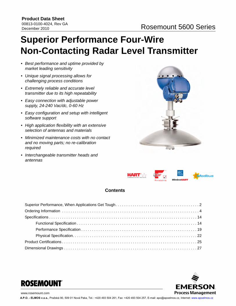
• Best performance and uptime provided bymarket leading sensitivity
• Unique signal processing allows for challenging process conditions
• Extremely reliable and accurate level transmitter due to its high repeatability
• Easy connection with adjustable power supply, 24-240 Vac/dc, 0-60 Hz
• Easy configuration and setup with intelligent software support
• High application flexibility with an extensive selection of antennas and materials
• Minimized maintenance costs with no contact and no moving parts; no re-calibration required
• Interchangeable transmitter heads and antennas
w
A
Contents
Superior Performance, When Applications Get Tough. . . . . . . . . . . . . . . . . . . . . . . . . . . . . . . . . . . . . . . 2
Ordering Information . . . . . . . . . . . . . . . . . . . . . . . . . . . . . . . . . . . . . . . . . . . . . . . . . . . . . . . . . . . . . . . . 4
Specifications . . . . . . . . . . . . . . . . . . . . . . . . . . . . . . . . . . . . . . . . . . . . . . . . . . . . . . . . . . . . . . . . . . . . . 14
Functional Specification . . . . . . . . . . . . . . . . . . . . . . . . . . . . . . . . . . . . . . . . . . . . . . . . . . . . . . . . 14
Performance Specification . . . . . . . . . . . . . . . . . . . . . . . . . . . . . . . . . . . . . . . . . . . . . . . . . . . . . . 19
Physical Specification. . . . . . . . . . . . . . . . . . . . . . . . . . . . . . . . . . . . . . . . . . . . . . . . . . . . . . . . . . 22
Product Certifications . . . . . . . . . . . . . . . . . . . . . . . . . . . . . . . . . . . . . . . . . . . . . . . . . . . . . . . . . . . . . . . 25
Dimensional Drawings . . . . . . . . . . . . . . . . . . . . . . . . . . . . . . . . . . . . . . . . . . . . . . . . . . . . . . . . . . . . . . 27
ww.rosemount.com
.P.O. - ELMOS v.o.s., Pražská 90, 509 01 Nová Paka, Tel.: +420 493 504 261, Fax: +420 493 504 257, E-mail: [email protected], Internet: www.apoelmos.cz
Product Data Sheet00813-0100-4024, Rev GA
December 2010Rosemount 5600 Series
Superior Performance, When Applications Get Tough
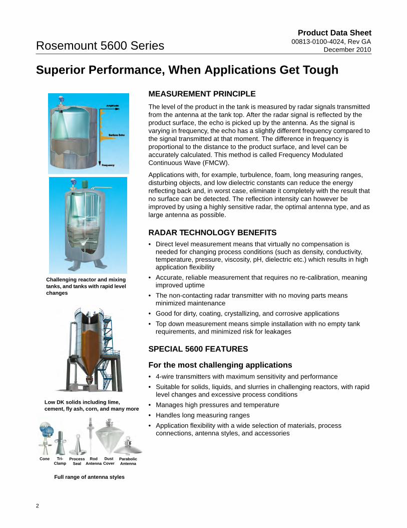
MEASUREMENT PRINCIPLE
The level of the product in the tank is measured by radar signals transmitted from the antenna at the tank top. After the radar signal is reflected by the product surface, the echo is picked up by the antenna. As the signal is varying in frequency, the echo has a slightly different frequency compared to the signal transmitted at that moment. The difference in frequency is proportional to the distance to the product surface, and level can be accurately calculated. This method is called Frequency Modulated Continuous Wave (FMCW).
Applications with, for example, turbulence, foam, long measuring ranges, disturbing objects, and low dielectric constants can reduce the energy reflecting back and, in worst case, eliminate it completely with the result that no surface can be detected. The reflection intensity can however be improved by using a highly sensitive radar, the optimal antenna type, and as large antenna as possible.
RADAR TECHNOLOGY BENEFITS• Direct level measurement means that virtually no compensation is
needed for changing process conditions (such as density, conductivity, temperature, pressure, viscosity, pH, dielectric etc.) which results in high application flexibility
• Accurate, reliable measurement that requires no re-calibration, meaning improved uptime
• The non-contacting radar transmitter with no moving parts means minimized maintenance
• Good for dirty, coating, crystallizing, and corrosive applications
• Top down measurement means simple installation with no empty tank requirements, and minimized risk for leakages
SPECIAL 5600 FEATURES
For the most challenging applications• 4-wire transmitters with maximum sensitivity and performance
• Suitable for solids, liquids, and slurries in challenging reactors, with rapid level changes and excessive process conditions
• Manages high pressures and temperature
• Handles long measuring ranges
• Application flexibility with a wide selection of materials, process connections, antenna styles, and accessories
Challenging reactor and mixing tanks, and tanks with rapid level changes
Low DK solids including lime, cement, fly ash, corn, and many more
Full range of antenna styles
Cone Tri-Clamp
Process Seal
Rod Antenna
Dust Cover
Parabolic Antenna
2
Product Data Sheet00813-0100-4024, Rev GADecember 2010 Rosemount 5600 Series
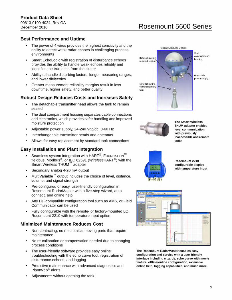
Best Performance and Uptime• The power of 4 wires provides the highest sensitivity and the
ability to detect weak radar echoes in challenging process environments
• Smart EchoLogic with registration of disturbance echoes provides the ability to handle weak echoes reliably and identifies the true echo from the clutter
• Ability to handle disturbing factors, longer measuring ranges, and lower dielectrics
• Greater measurement reliability margins result in less downtime, higher safety, and better quality
Robust Design Reduces Costs and Increases Safety• The detachable transmitter head allows the tank to remain
sealed
• The dual compartment housing separates cable connections and electronics, which provides safer handling and improved moisture protection
• Adjustable power supply, 24-240 Vac/dc, 0-60 Hz
• Interchangeable transmitter heads and antennas
• Allows for easy replacement by standard tank connections
Easy Installation and Plant Integration• Seamless system integration with HART®, FOUNDATION™
fieldbus, Modbus®, or IEC 62591 (WirelessHART®) with the Smart Wireless THUM™ adapter
• Secondary analog 4-20 mA output
• MultiVariable™ output includes the choice of level, distance, volume, and signal strength
• Pre-configured or easy, user-friendly configuration in Rosemount RadarMaster with a five-step wizard, auto connect, and online help
• Any DD-compatible configuration tool such as AMS, or Field Communicator can be used
• Fully configurable with the remote- or factory-mounted LOI Rosemount 2210 with temperature input option
Minimized Maintenance Reduces Cost• Non-contacting, no mechanical moving parts that require
maintenance
• No re-calibration or compensation needed due to changing process conditions
• The user-friendly software provides easy online troubleshooting with the echo curve tool, registration of disturbance echoes, and logging
• Predictive maintenance with advanced diagnostics and PlantWeb® alerts
• Adjustments without opening the tank
The Smart Wireless THUM adapter enables level communication with previously inaccessible and remote tanks
Rosemount 2210 configurable display with temperature input
The Rosemount RadarMaster enables easy configuration and service with a user-friendly interface including wizards, echo curve with movie feature, offline/online configuration, extensive online help, logging capabilities, and much more.
3
Product Data Sheet00813-0100-4024, Rev GA
December 2010Rosemount 5600 Series
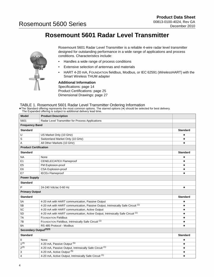
Rosemount 5601 Radar Level Transmitter
Rosemount 5601 Radar Level Transmitter is a reliable 4-wire radar level transmitter designed for outstanding performance in a wide range of applications and process conditions. Characteristics include:
• Handles a wide range of process conditions
• Extensive selection of antennas and materials
• HART 4-20 mA, FOUNDATION fieldbus, Modbus, or IEC 62591 (WirelessHART) with the Smart Wireless THUM adapter
Additional InformationSpecifications: page 14Product Certifications: page 25Dimensional Drawings: page 27
Ordering Information
TABLE 1. Rosemount 5601 Radar Level Transmitter Ordering Information★The Standard offering represents the most common options. The starred options (★) should be selected for best delivery.
The Expanded offering is subject to additional delivery lead time.
Model Product Description
5601 Radar Level Transmitter for Process Applications
Frequency Band
Standard Standard
U US Market Only (10 GHz) ★
S Switzerland Market Only (10 GHz) ★
A All Other Markets (10 GHz) ★
Product Certification
Standard Standard
NA None ★
E1 CENELEC/ATEX Flameproof ★
E5 FM Explosion-proof ★
E6 CSA Explosion-proof ★
E7 IECEx Flameproof ★
Power Supply
Standard
P 24-240 Vdc/ac 0-60 Hz ★
Primary Output
Standard Standard
5A 4-20 mA with HART communication, Passive Output ★
5B 4-20 mA with HART communication, Passive Output, Intrinsically Safe Circuit (1) ★
5C 4-20 mA with HART communication, Active Output ★
5D 4-20 mA with HART communication, Active Output, Intrinsically Safe Circuit (1) ★
7A FOUNDATION Fieldbus ★
7B FOUNDATION Fieldbus, Intrinsically Safe Circuit (1) ★
8A RS 485 Protocol - Modbus ★
Secondary Output(2)(3)
Standard Standard
0 None ★
1(4) 4-20 mA, Passive Output (5) ★
2(4) 4-20 mA, Passive Output, Intrinsically Safe Circuit (1) ★
3 4-20 mA, Active Output (5) ★
4 4-20 mA, Active Output, Intrinsically Safe Circuit (1) ★
4
Product Data Sheet00813-0100-4024, Rev GADecember 2010 Rosemount 5600 Series
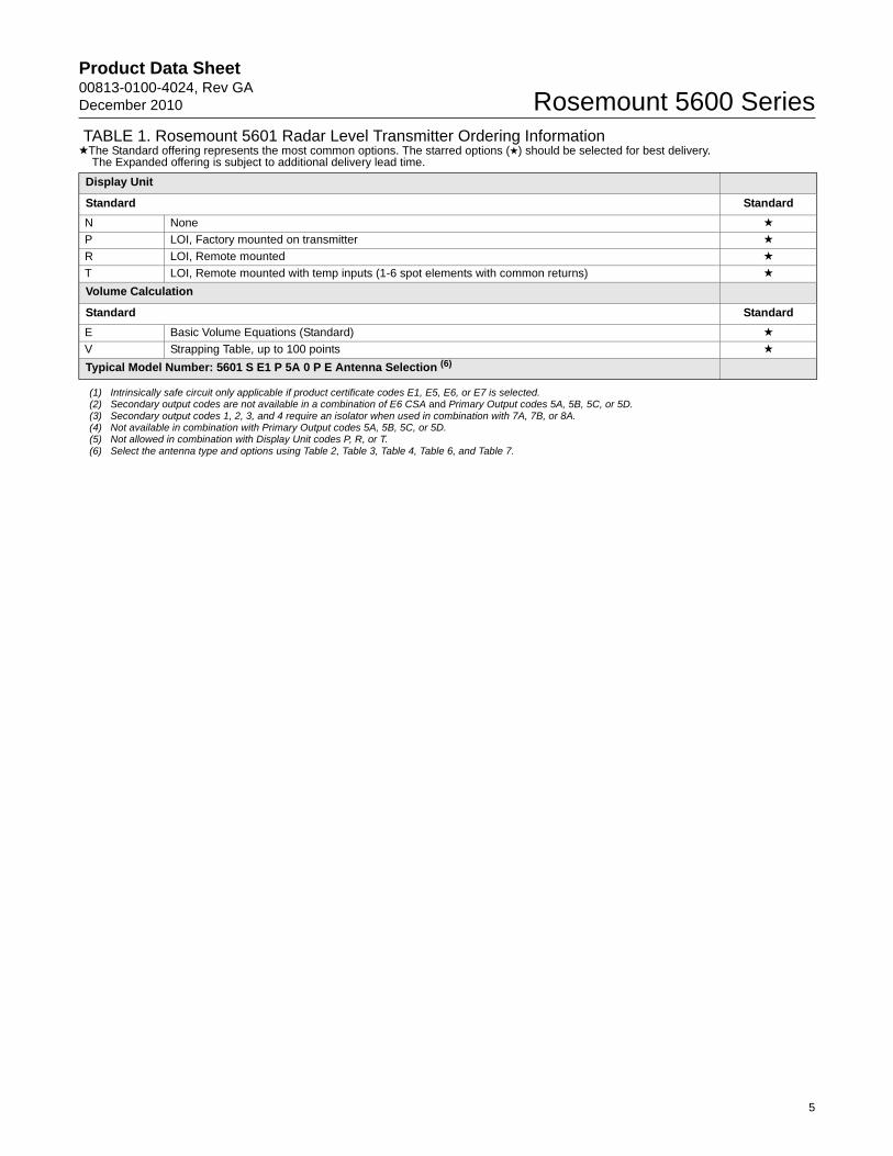
Display Unit
Standard Standard
N None ★
P LOI, Factory mounted on transmitter ★
R LOI, Remote mounted ★
T LOI, Remote mounted with temp inputs (1-6 spot elements with common returns) ★
Volume Calculation
Standard Standard
E Basic Volume Equations (Standard) ★
V Strapping Table, up to 100 points ★
Typical Model Number: 5601 S E1 P 5A 0 P E Antenna Selection (6)
(1) Intrinsically safe circuit only applicable if product certificate codes E1, E5, E6, or E7 is selected.(2) Secondary output codes are not available in a combination of E6 CSA and Primary Output codes 5A, 5B, 5C, or 5D.(3) Secondary output codes 1, 2, 3, and 4 require an isolator when used in combination with 7A, 7B, or 8A.(4) Not available in combination with Primary Output codes 5A, 5B, 5C, or 5D.(5) Not allowed in combination with Display Unit codes P, R, or T.(6) Select the antenna type and options using Table 2, Table 3, Table 4, Table 6, and Table 7.
TABLE 1. Rosemount 5601 Radar Level Transmitter Ordering Information★The Standard offering represents the most common options. The starred options (★) should be selected for best delivery.
The Expanded offering is subject to additional delivery lead time.
5
Product Data Sheet00813-0100-4024, Rev GA
December 2010Rosemount 5600 Series
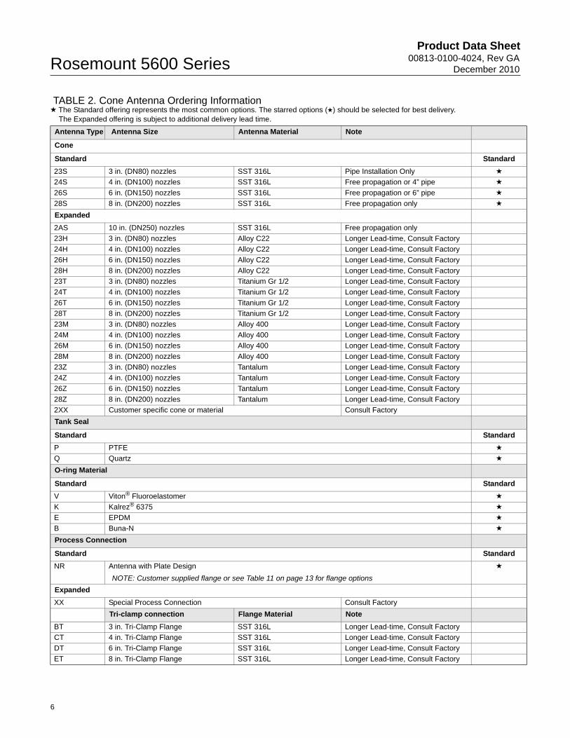
TABLE 2. Cone Antenna Ordering Information★ The Standard offering represents the most common options. The starred options (★) should be selected for best delivery.
The Expanded offering is subject to additional delivery lead time.
Antenna Type Antenna Size Antenna Material Note
Cone
Standard Standard
23S 3 in. (DN80) nozzles SST 316L Pipe Installation Only ★
24S 4 in. (DN100) nozzles SST 316L Free propagation or 4” pipe ★
26S 6 in. (DN150) nozzles SST 316L Free propagation or 6” pipe ★
28S 8 in. (DN200) nozzles SST 316L Free propagation only ★
Expanded
2AS 10 in. (DN250) nozzles SST 316L Free propagation only
23H 3 in. (DN80) nozzles Alloy C22 Longer Lead-time, Consult Factory
24H 4 in. (DN100) nozzles Alloy C22 Longer Lead-time, Consult Factory
26H 6 in. (DN150) nozzles Alloy C22 Longer Lead-time, Consult Factory
28H 8 in. (DN200) nozzles Alloy C22 Longer Lead-time, Consult Factory
23T 3 in. (DN80) nozzles Titanium Gr 1/2 Longer Lead-time, Consult Factory
24T 4 in. (DN100) nozzles Titanium Gr 1/2 Longer Lead-time, Consult Factory
26T 6 in. (DN150) nozzles Titanium Gr 1/2 Longer Lead-time, Consult Factory
28T 8 in. (DN200) nozzles Titanium Gr 1/2 Longer Lead-time, Consult Factory
23M 3 in. (DN80) nozzles Alloy 400 Longer Lead-time, Consult Factory
24M 4 in. (DN100) nozzles Alloy 400 Longer Lead-time, Consult Factory
26M 6 in. (DN150) nozzles Alloy 400 Longer Lead-time, Consult Factory
28M 8 in. (DN200) nozzles Alloy 400 Longer Lead-time, Consult Factory
23Z 3 in. (DN80) nozzles Tantalum Longer Lead-time, Consult Factory
24Z 4 in. (DN100) nozzles Tantalum Longer Lead-time, Consult Factory
26Z 6 in. (DN150) nozzles Tantalum Longer Lead-time, Consult Factory
28Z 8 in. (DN200) nozzles Tantalum Longer Lead-time, Consult Factory
2XX Customer specific cone or material Consult Factory
Tank Seal
Standard Standard
P PTFE ★
Q Quartz ★
O-ring Material
Standard Standard
V Viton® Fluoroelastomer ★
K Kalrez® 6375 ★
E EPDM ★
B Buna-N ★
Process Connection
Standard Standard
NR Antenna with Plate Design
NOTE: Customer supplied flange or see Table 11 on page 13 for flange options
★
Expanded
XX Special Process Connection Consult Factory
Tri-clamp connection Flange Material Note
BT 3 in. Tri-Clamp Flange SST 316L Longer Lead-time, Consult Factory
CT 4 in. Tri-Clamp Flange SST 316L Longer Lead-time, Consult Factory
DT 6 in. Tri-Clamp Flange SST 316L Longer Lead-time, Consult Factory
ET 8 in. Tri-Clamp Flange SST 316L Longer Lead-time, Consult Factory
6
Product Data Sheet00813-0100-4024, Rev GADecember 2010 Rosemount 5600 Series
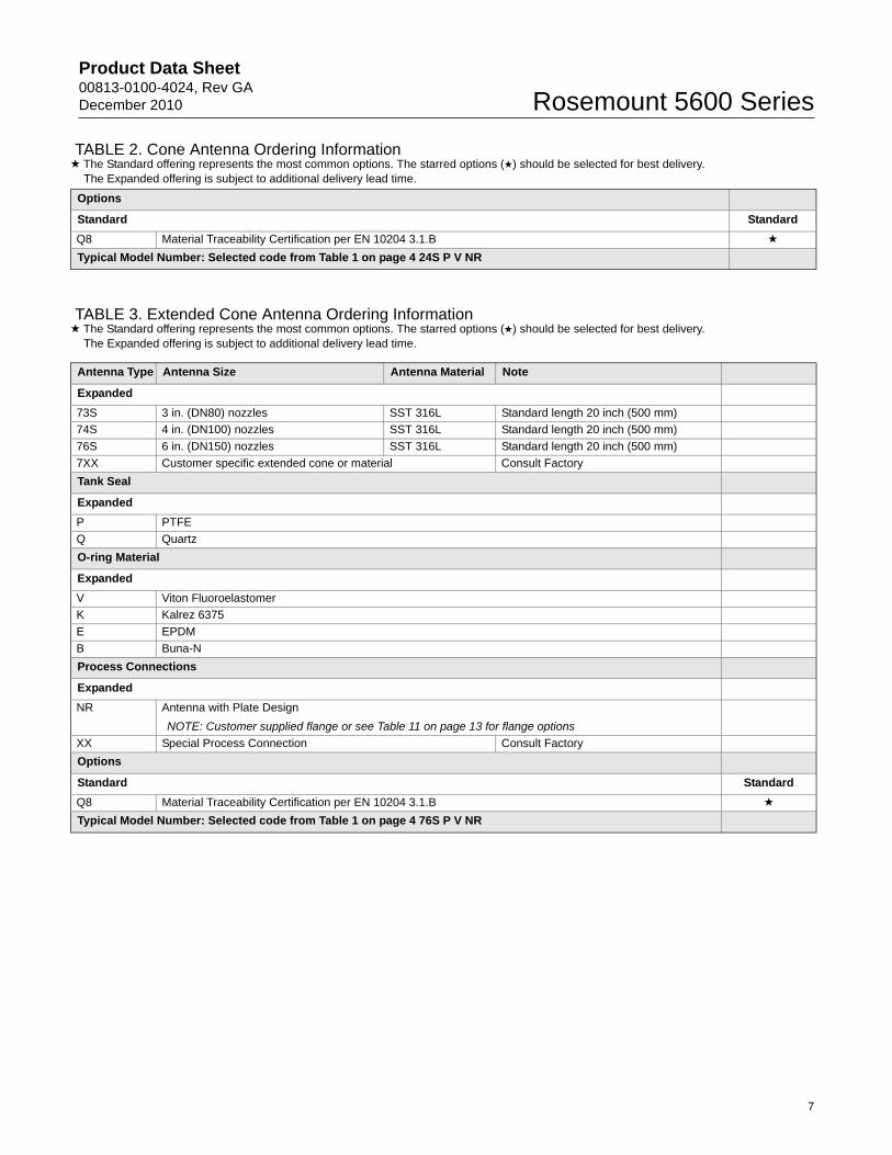
TABLE 3. Extended Cone Antenna Ordering Information★ The Standard offering represents the most common options. The starred options (★) should be selected for best delivery.
The Expanded offering is subject to additional delivery lead time.
Options
Standard Standard
Q8 Material Traceability Certification per EN 10204 3.1.B ★
Typical Model Number: Selected code from Table 1 on page 4 24S P V NR
TABLE 2. Cone Antenna Ordering Information★ The Standard offering represents the most common options. The starred options (★) should be selected for best delivery.
The Expanded offering is subject to additional delivery lead time.
Antenna Type Antenna Size Antenna Material Note
Expanded
73S 3 in. (DN80) nozzles SST 316L Standard length 20 inch (500 mm)
74S 4 in. (DN100) nozzles SST 316L Standard length 20 inch (500 mm)
76S 6 in. (DN150) nozzles SST 316L Standard length 20 inch (500 mm)
7XX Customer specific extended cone or material Consult Factory
Tank Seal
Expanded
P PTFE
Q Quartz
O-ring Material
Expanded
V Viton Fluoroelastomer
K Kalrez 6375
E EPDM
B Buna-N
Process Connections
Expanded
NR Antenna with Plate Design
NOTE: Customer supplied flange or see Table 11 on page 13 for flange options
XX Special Process Connection Consult Factory
Options
Standard Standard
Q8 Material Traceability Certification per EN 10204 3.1.B ★
Typical Model Number: Selected code from Table 1 on page 4 76S P V NR
7
Product Data Sheet00813-0100-4024, Rev GA
December 2010Rosemount 5600 Series
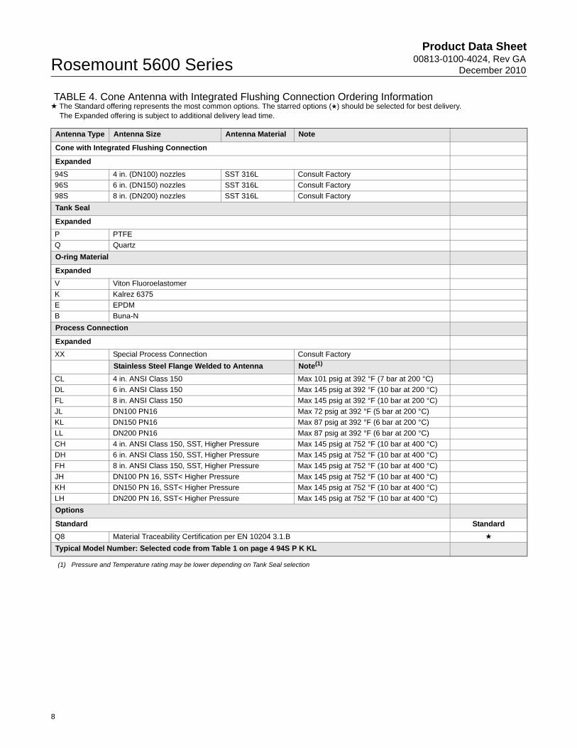
TABLE 4. Cone Antenna with Integrated Flushing Connection Ordering Information★ The Standard offering represents the most common options. The starred options (★) should be selected for best delivery.
The Expanded offering is subject to additional delivery lead time.
Antenna Type Antenna Size Antenna Material Note
Cone with Integrated Flushing Connection
Expanded
94S 4 in. (DN100) nozzles SST 316L Consult Factory
96S 6 in. (DN150) nozzles SST 316L Consult Factory
98S 8 in. (DN200) nozzles SST 316L Consult Factory
Tank Seal
Expanded
P PTFE
Q Quartz
O-ring Material
Expanded
V Viton Fluoroelastomer
K Kalrez 6375
E EPDM
B Buna-N
Process Connection
Expanded
XX Special Process Connection Consult Factory
Stainless Steel Flange Welded to Antenna Note(1)
(1) Pressure and Temperature rating may be lower depending on Tank Seal selection
CL 4 in. ANSI Class 150 Max 101 psig at 392 °F (7 bar at 200 °C)
DL 6 in. ANSI Class 150 Max 145 psig at 392 °F (10 bar at 200 °C)
FL 8 in. ANSI Class 150 Max 145 psig at 392 °F (10 bar at 200 °C)
JL DN100 PN16 Max 72 psig at 392 °F (5 bar at 200 °C)
KL DN150 PN16 Max 87 psig at 392 °F (6 bar at 200 °C)
LL DN200 PN16 Max 87 psig at 392 °F (6 bar at 200 °C)
CH 4 in. ANSI Class 150, SST, Higher Pressure Max 145 psig at 752 °F (10 bar at 400 °C)
DH 6 in. ANSI Class 150, SST, Higher Pressure Max 145 psig at 752 °F (10 bar at 400 °C)
FH 8 in. ANSI Class 150, SST, Higher Pressure Max 145 psig at 752 °F (10 bar at 400 °C)
JH DN100 PN 16, SST< Higher Pressure Max 145 psig at 752 °F (10 bar at 400 °C)
KH DN150 PN 16, SST< Higher Pressure Max 145 psig at 752 °F (10 bar at 400 °C)
LH DN200 PN 16, SST< Higher Pressure Max 145 psig at 752 °F (10 bar at 400 °C)
Options
Standard Standard
Q8 Material Traceability Certification per EN 10204 3.1.B ★
Typical Model Number: Selected code from Table 1 on page 4 94S P K KL
8
Product Data Sheet00813-0100-4024, Rev GADecember 2010 Rosemount 5600 Series
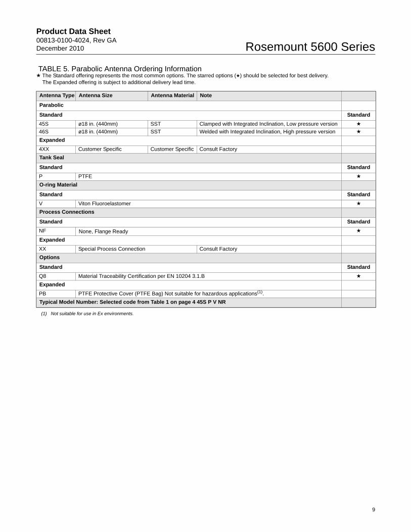
TABLE 5. Parabolic Antenna Ordering Information★ The Standard offering represents the most common options. The starred options (★) should be selected for best delivery.
The Expanded offering is subject to additional delivery lead time.
Antenna Type Antenna Size Antenna Material Note
Parabolic
Standard Standard
45S ø18 in. (440mm) SST Clamped with Integrated Inclination, Low pressure version ★
46S ø18 in. (440mm) SST Welded with Integrated Inclination, High pressure version ★
Expanded
4XX Customer Specific Customer Specific Consult Factory
Tank Seal
Standard Standard
P PTFE ★
O-ring Material
Standard Standard
V Viton Fluoroelastomer ★
Process Connections
Standard Standard
NF None, Flange Ready ★
Expanded
XX Special Process Connection Consult Factory
Options
Standard Standard
Q8 Material Traceability Certification per EN 10204 3.1.B ★
Expanded
PB PTFE Protective Cover (PTFE Bag) Not suitable for hazardous applications(1).
(1) Not suitable for use in Ex environments.
Typical Model Number: Selected code from Table 1 on page 4 45S P V NR
9
Product Data Sheet00813-0100-4024, Rev GA
December 2010Rosemount 5600 Series
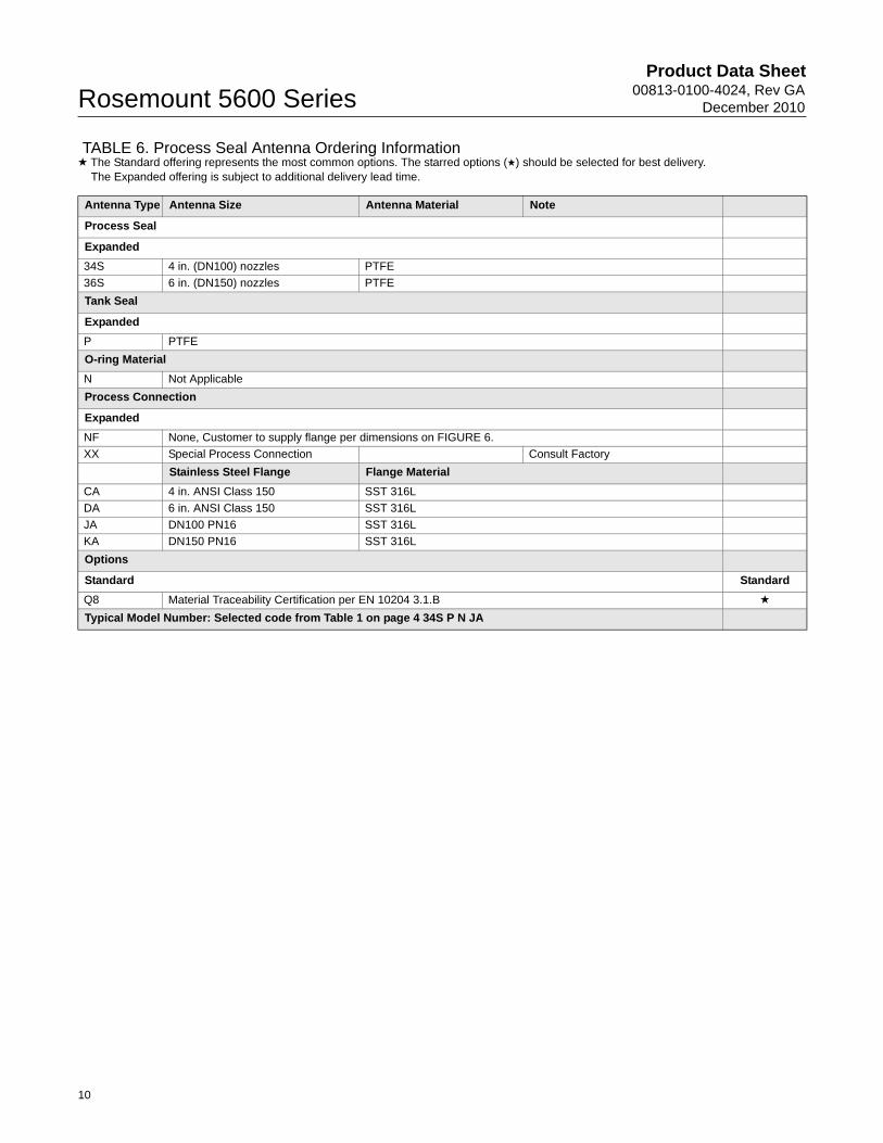
TABLE 6. Process Seal Antenna Ordering Information★ The Standard offering represents the most common options. The starred options (★) should be selected for best delivery.
The Expanded offering is subject to additional delivery lead time.
Antenna Type Antenna Size Antenna Material Note
Process Seal
Expanded
34S 4 in. (DN100) nozzles PTFE
36S 6 in. (DN150) nozzles PTFE
Tank Seal
Expanded
P PTFE
O-ring Material
N Not Applicable
Process Connection
Expanded
NF None, Customer to supply flange per dimensions on FIGURE 6.
XX Special Process Connection Consult Factory
Stainless Steel Flange Flange Material
CA 4 in. ANSI Class 150 SST 316L
DA 6 in. ANSI Class 150 SST 316L
JA DN100 PN16 SST 316L
KA DN150 PN16 SST 316L
Options
Standard Standard
Q8 Material Traceability Certification per EN 10204 3.1.B ★
Typical Model Number: Selected code from Table 1 on page 4 34S P N JA
10
Product Data Sheet00813-0100-4024, Rev GADecember 2010 Rosemount 5600 Series
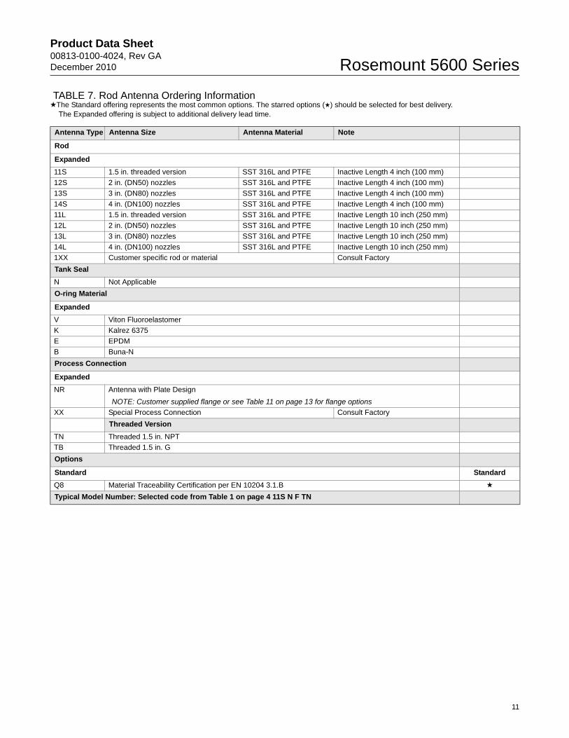
TABLE 7. Rod Antenna Ordering Information★The Standard offering represents the most common options. The starred options (★) should be selected for best delivery.
The Expanded offering is subject to additional delivery lead time.
Antenna Type Antenna Size Antenna Material Note
Rod
Expanded
11S 1.5 in. threaded version SST 316L and PTFE Inactive Length 4 inch (100 mm)
12S 2 in. (DN50) nozzles SST 316L and PTFE Inactive Length 4 inch (100 mm)
13S 3 in. (DN80) nozzles SST 316L and PTFE Inactive Length 4 inch (100 mm)
14S 4 in. (DN100) nozzles SST 316L and PTFE Inactive Length 4 inch (100 mm)
11L 1.5 in. threaded version SST 316L and PTFE Inactive Length 10 inch (250 mm)
12L 2 in. (DN50) nozzles SST 316L and PTFE Inactive Length 10 inch (250 mm)
13L 3 in. (DN80) nozzles SST 316L and PTFE Inactive Length 10 inch (250 mm)
14L 4 in. (DN100) nozzles SST 316L and PTFE Inactive Length 10 inch (250 mm)
1XX Customer specific rod or material Consult Factory
Tank Seal
N Not Applicable
O-ring Material
Expanded
V Viton Fluoroelastomer
K Kalrez 6375
E EPDM
B Buna-N
Process Connection
Expanded
NR Antenna with Plate Design
NOTE: Customer supplied flange or see Table 11 on page 13 for flange options
XX Special Process Connection Consult Factory
Threaded Version
TN Threaded 1.5 in. NPT
TB Threaded 1.5 in. G
Options
Standard Standard
Q8 Material Traceability Certification per EN 10204 3.1.B ★
Typical Model Number: Selected code from Table 1 on page 4 11S N F TN
11
Product Data Sheet00813-0100-4024, Rev GA
December 2010Rosemount 5600 Series
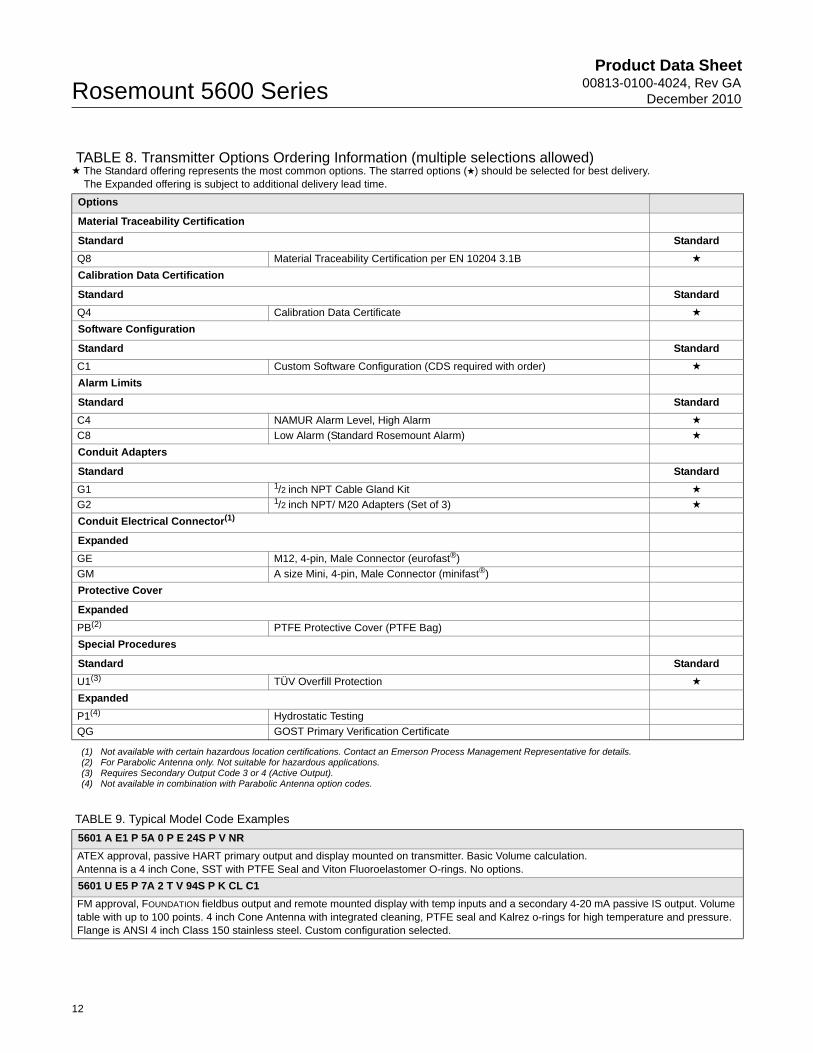
TABLE 8. Transmitter Options Ordering Information (multiple selections allowed)★ The Standard offering represents the most common options. The starred options (★) should be selected for best delivery.
The Expanded offering is subject to additional delivery lead time.
Options
Material Traceability Certification
Standard Standard
Q8 Material Traceability Certification per EN 10204 3.1B ★
Calibration Data Certification
Standard Standard
Q4 Calibration Data Certificate ★
Software Configuration
Standard Standard
C1 Custom Software Configuration (CDS required with order) ★
Alarm Limits
Standard Standard
C4 NAMUR Alarm Level, High Alarm ★
C8 Low Alarm (Standard Rosemount Alarm) ★
Conduit Adapters
Standard Standard
G1 1/2 inch NPT Cable Gland Kit ★
G2 1/2 inch NPT/ M20 Adapters (Set of 3) ★
Conduit Electrical Connector(1)
Expanded
GE M12, 4-pin, Male Connector (eurofast®)
GM A size Mini, 4-pin, Male Connector (minifast®)
Protective Cover
Expanded
PB(2) PTFE Protective Cover (PTFE Bag)
Special Procedures
Standard Standard
U1(3) TÜV Overfill Protection ★
Expanded
P1(4) Hydrostatic Testing
QG GOST Primary Verification Certificate
(1) Not available with certain hazardous location certifications. Contact an Emerson Process Management Representative for details.(2) For Parabolic Antenna only. Not suitable for hazardous applications.(3) Requires Secondary Output Code 3 or 4 (Active Output).(4) Not available in combination with Parabolic Antenna option codes.
TABLE 9. Typical Model Code Examples
5601 A E1 P 5A 0 P E 24S P V NR
ATEX approval, passive HART primary output and display mounted on transmitter. Basic Volume calculation.Antenna is a 4 inch Cone, SST with PTFE Seal and Viton Fluoroelastomer O-rings. No options.
5601 U E5 P 7A 2 T V 94S P K CL C1
FM approval, FOUNDATION fieldbus output and remote mounted display with temp inputs and a secondary 4-20 mA passive IS output. Volume table with up to 100 points. 4 inch Cone Antenna with integrated cleaning, PTFE seal and Kalrez o-rings for high temperature and pressure. Flange is ANSI 4 inch Class 150 stainless steel. Custom configuration selected.
12
Product Data Sheet00813-0100-4024, Rev GADecember 2010 Rosemount 5600 Series
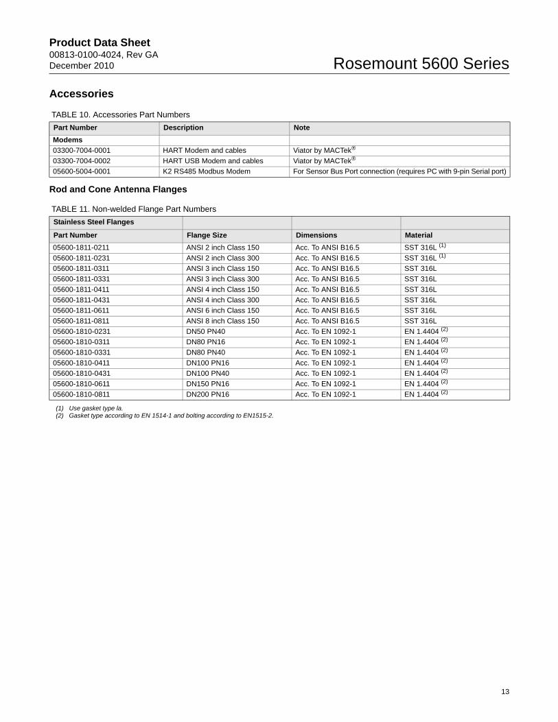
Accessories
Rod and Cone Antenna Flanges
TABLE 10. Accessories Part Numbers
Part Number Description Note
Modems
03300-7004-0001 HART Modem and cables Viator by MACTek®
03300-7004-0002 HART USB Modem and cables Viator by MACTek®
05600-5004-0001 K2 RS485 Modbus Modem For Sensor Bus Port connection (requires PC with 9-pin Serial port)
TABLE 11. Non-welded Flange Part Numbers
Stainless Steel Flanges
Part Number Flange Size Dimensions Material
05600-1811-0211 ANSI 2 inch Class 150 Acc. To ANSI B16.5 SST 316L (1)
05600-1811-0231 ANSI 2 inch Class 300 Acc. To ANSI B16.5 SST 316L (1)
05600-1811-0311 ANSI 3 inch Class 150 Acc. To ANSI B16.5 SST 316L
05600-1811-0331 ANSI 3 inch Class 300 Acc. To ANSI B16.5 SST 316L
05600-1811-0411 ANSI 4 inch Class 150 Acc. To ANSI B16.5 SST 316L
05600-1811-0431 ANSI 4 inch Class 300 Acc. To ANSI B16.5 SST 316L
05600-1811-0611 ANSI 6 inch Class 150 Acc. To ANSI B16.5 SST 316L
05600-1811-0811 ANSI 8 inch Class 150 Acc. To ANSI B16.5 SST 316L
05600-1810-0231 DN50 PN40 Acc. To EN 1092-1 EN 1.4404 (2)
05600-1810-0311 DN80 PN16 Acc. To EN 1092-1 EN 1.4404 (2)
05600-1810-0331 DN80 PN40 Acc. To EN 1092-1 EN 1.4404 (2)
05600-1810-0411 DN100 PN16 Acc. To EN 1092-1 EN 1.4404 (2)
05600-1810-0431 DN100 PN40 Acc. To EN 1092-1 EN 1.4404 (2)
05600-1810-0611 DN150 PN16 Acc. To EN 1092-1 EN 1.4404 (2)
05600-1810-0811 DN200 PN16 Acc. To EN 1092-1 EN 1.4404 (2)
(1) Use gasket type la.(2) Gasket type according to EN 1514-1 and bolting according to EN1515-2.
13
Product Data Sheet00813-0100-4024, Rev GA
December 2010Rosemount 5600 Series
14
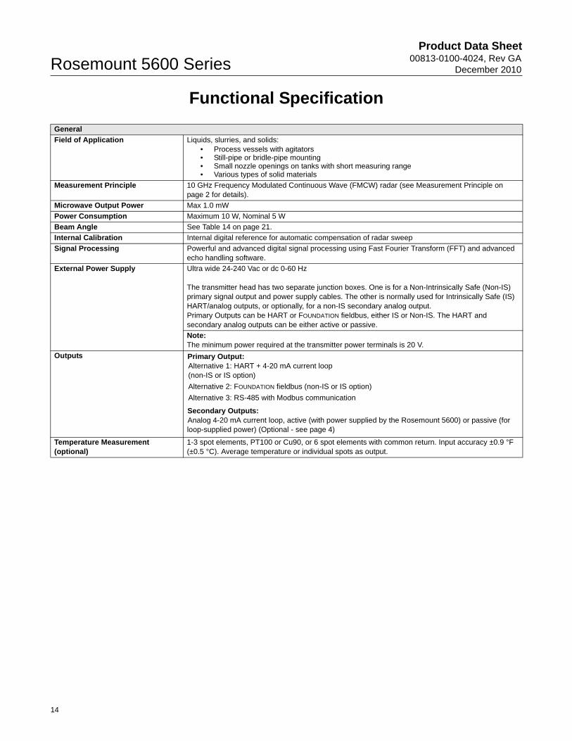
Functional Specification
General
Field of Application Liquids, slurries, and solids:• Process vessels with agitators• Still-pipe or bridle-pipe mounting• Small nozzle openings on tanks with short measuring range• Various types of solid materials
Measurement Principle 10 GHz Frequency Modulated Continuous Wave (FMCW) radar (see Measurement Principle on page 2 for details).
Microwave Output Power Max 1.0 mW
Power Consumption Maximum 10 W, Nominal 5 W
Beam Angle See Table 14 on page 21.
Internal Calibration Internal digital reference for automatic compensation of radar sweep
Signal Processing Powerful and advanced digital signal processing using Fast Fourier Transform (FFT) and advanced echo handling software.
External Power Supply Ultra wide 24-240 Vac or dc 0-60 Hz
The transmitter head has two separate junction boxes. One is for a Non-Intrinsically Safe (Non-IS) primary signal output and power supply cables. The other is normally used for Intrinsically Safe (IS) HART/analog outputs, or optionally, for a non-IS secondary analog output.Primary Outputs can be HART or FOUNDATION fieldbus, either IS or Non-IS. The HART and secondary analog outputs can be either active or passive.
Note:The minimum power required at the transmitter power terminals is 20 V.
Outputs Primary Output:Alternative 1: HART + 4-20 mA current loop (non-IS or IS option)
Alternative 2: FOUNDATION fieldbus (non-IS or IS option)
Alternative 3: RS-485 with Modbus communication
Secondary Outputs:Analog 4-20 mA current loop, active (with power supplied by the Rosemount 5600) or passive (for loop-supplied power) (Optional - see page 4)
Temperature Measurement (optional)
1-3 spot elements, PT100 or Cu90, or 6 spot elements with common return. Input accuracy ±0.9 °F (±0.5 °C). Average temperature or individual spots as output.
Product Data Sheet00813-0100-4024, Rev GADecember 2010 Rosemount 5600 Series
15
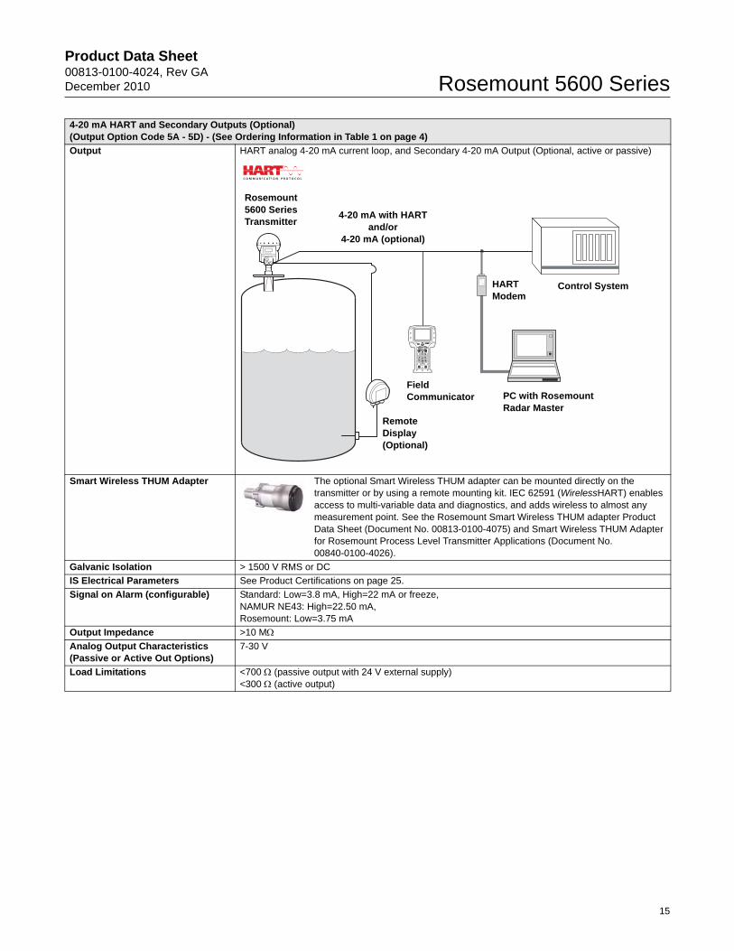
4-20 mA HART and Secondary Outputs (Optional) (Output Option Code 5A - 5D) - (See Ordering Information in Table 1 on page 4)
Output HART analog 4-20 mA current loop, and Secondary 4-20 mA Output (Optional, active or passive)
Smart Wireless THUM Adapter The optional Smart Wireless THUM adapter can be mounted directly on the transmitter or by using a remote mounting kit. IEC 62591 (WirelessHART) enables access to multi-variable data and diagnostics, and adds wireless to almost any measurement point. See the Rosemount Smart Wireless THUM adapter Product Data Sheet (Document No. 00813-0100-4075) and Smart Wireless THUM Adapter for Rosemount Process Level Transmitter Applications (Document No. 00840-0100-4026).
Galvanic Isolation > 1500 V RMS or DC
IS Electrical Parameters See Product Certifications on page 25.
Signal on Alarm (configurable) Standard: Low=3.8 mA, High=22 mA or freeze,NAMUR NE43: High=22.50 mA, Rosemount: Low=3.75 mA
Output Impedance >10 MAnalog Output Characteristics (Passive or Active Out Options)
7-30 V
Load Limitations <700 (passive output with 24 V external supply)<300 (active output)
Rosemount 5600 Series Transmitter
4-20 mA with HART and/or
4-20 mA (optional)
Remote Display (Optional)
FieldCommunicator
HART Modem
Control System
PC with Rosemount Radar Master
Product Data Sheet00813-0100-4024, Rev GA
December 2010Rosemount 5600 Series
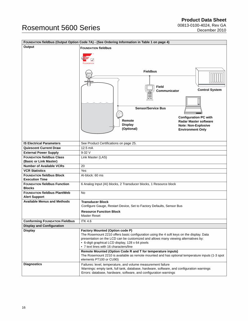
FOUNDATION fieldbus (Output Option Code 7A) - (See Ordering Information in Table 1 on page 4)
Output
IS Electrical Parameters See Product Certifications on page 25.
Quiescent Current Draw 12.5 mA
External Power Supply 9-32 V
FOUNDATION fieldbus Class(Basic or Link Master)
Link Master (LAS)
Number of Available VCRs 20
VCR Statistics Yes
FOUNDATION fieldbus Block Execution Time
AI-block: 60 ms
FOUNDATION fieldbus Function Blocks
6 Analog Input (AI) blocks, 2 Transducer blocks, 1 Resource block
FOUNDATION fieldbus PlantWeb Alert Support
No
Available Menus and Methods Transducer BlockConfigure Gauge, Restart Device, Set to Factory Defaults, Sensor Bus
Resource Function BlockMaster Reset
Conforming FOUNDATION Fieldbus ITK 4.6
Display and Configuration
Display Factory Mounted (Option code P)The Rosemount 2210 offers basic configuration using the 4 soft keys on the display. Data presentation on the LCD can be customized and allows many viewing alternatives by:• 6-digit graphical LCD display, 128 x 64 pixels• 7 text lines with 16 characters/line
Remote Mounted (Option Code R and T for temperature inputs)The Rosemount 2210 is available as remote mounted and has optional temperature inputs (1-3 spot elements PT100 or CU90)
Diagnostics Failures: level, temperature, and volume measurement failureWarnings: empty tank, full tank, database, hardware, software, and configuration warningsErrors: database, hardware, software, and configuration warnings
FOUNDATION fieldbus
Sensor/Service Bus
Remote Display (Optional)
FieldCommunicator
Fieldbus
Control System
Configuration PC with Radar Master softwareNote: Non-Explosive Environment Only
16
Product Data Sheet00813-0100-4024, Rev GADecember 2010 Rosemount 5600 Series
17
Configuration Tools Emerson Field Communicator (e.g. 375/475 Field Communicator), Rosemount Radar Master (RRM) software package (included with delivery of transmitter), Emerson AMS™ Device Manager or DeltaV® or any other Device Description (DD) compatible host systems. Certificates are available from all major host system vendors.
Notes:• To communicate using RRM or AMS Device Manager, a HART modem is required. The HART
modem is available as an RS232 or USB version (see Accessories on page 13).• The transmitter can be pre-configured by selecting option code C1 (see page 12) and sending a
complete Configuration Data Sheet (CDS). The CDS is available from www.rosemount.com.
Output Units Level and Distance: ft, inch, m, cm, or mmVolume: ft3, inch3, US gals, Imp gals, barrels, yd3, m3, or litersLevel Rate: ft/s, m/sTemperature: °F, °C
Output Variables Level, Distance, Volume, Level Rate, Signal Strength, Used defined, Temperature (1-6), and Average Temperature
Damping 0-60 s (2 s, default value)
Temperature and Pressure Limits
Ambient Temperature -40 to 70 °C (-40 to 158 °F)LCD Readable between: -20 to 70 °C (-4 to 158 °F)
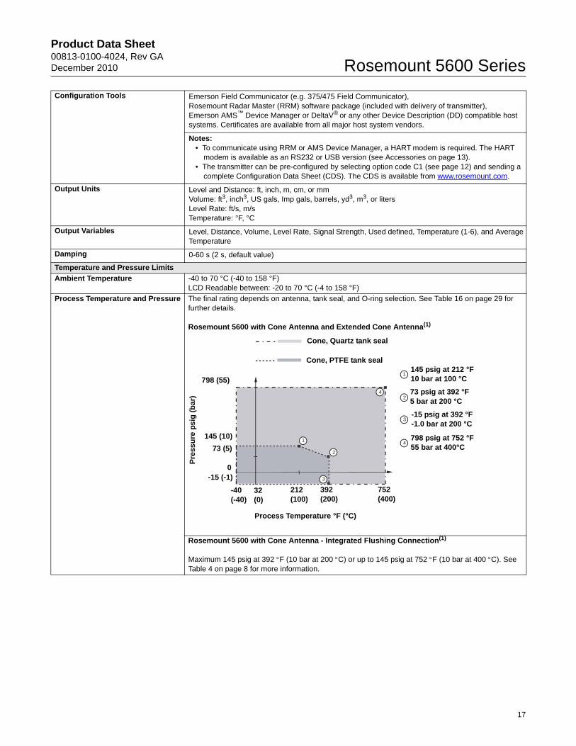
Process Temperature and Pressure The final rating depends on antenna, tank seal, and O-ring selection. See Table 16 on page 29 for further details.
Rosemount 5600 with Cone Antenna and Extended Cone Antenna(1)
Rosemount 5600 with Cone Antenna - Integrated Flushing Connection(1)
Maximum 145 psig at 392 F (10 bar at 200 C) or up to 145 psig at 752 F (10 bar at 400 C). See Table 4 on page 8 for more information.
1
2
3
1
2
3
4
4
145 psig at 212 °F10 bar at 100 °C
73 psig at 392 °F5 bar at 200 °C
-15 psig at 392 °F-1.0 bar at 200 °C
798 psig at 752 °F55 bar at 400°C
Cone, Quartz tank seal
Cone, PTFE tank seal
798 (55)
Pre
ssu
re p
sig
(b
ar)
145 (10)
73 (5)
0 -15 (-1)
-40(-40)
32(0)
212(100)
392(200)
752(400)
Process Temperature °F (°C)
Product Data Sheet00813-0100-4024, Rev GA
December 2010Rosemount 5600 Series
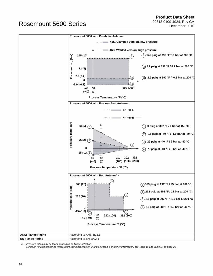
Rosemount 5600 with Parabolic Antenna
Rosemount 5600 with Process Seal Antenna
Rosemount 5600 with Rod Antenna(1)
ANSI Flange Rating According to ANSI B16.5
EN Flange Rating According to EN 1092-1
(1) Pressure rating may be lower depending on flange selection.Minimum / maximum flange temperature rating depends on O-ring selection. For further information, see Table 16 and Table 17 on page 29.
1
2
3
1
2
3
Pre
ssu
re p
sig
(b
ar) 145 psig at 392 °F/ 10 bar at 200 °C
2.9 psig at 392 °F / 0.2 bar at 200 °C
-2.9 psig at 392 °F / -0.2 bar at 200 °C
45S, Clamped version, low pressure
46S, Welded version, high pressure
145 (10)
73 (5)
2.9 (0.2)
0
-2.9 (-0.2) -40
(-40)32(0)
392 (200)
Process Temperature °F (°C)
1
2
4
2
3
4
3
1
Pre
ssu
re p
sig
(b
ar)
73 (5)
29(2)
0
-15 (-1)
-40(-40)
32(0)
212(100)
302(150)
392(200)
Process Temperature °F (°C)
6” PTFE
4” PTFE
0 psig at 302 °F / 0 bar at 150 °C
-15 psig at -40 °F / -1.0 bar at -40 °C
29 psig at -40 °F / 2 bar at -40 °C
73 psig at -40 °F / 5 bar at -40 °C
1
2
34
1
2
3
4
Process Temperature °F (°C)
Pre
ssu
re p
sig
(b
ar)
363 (25)
232 (16)
0-15 (-1.0)
-40 (-40)32 (0)
212 (100) 392 (200)
363 psig at 212 °F / 25 bar at 100 °C
232 psig at 392 °F / 16 bar at 200 °C
-15 psig at 392 °F / -1.0 bar at 200 °C
-15 psig at -40 °F / -1.0 bar at -40 °C
18
Product Data Sheet00813-0100-4024, Rev GADecember 2010 Rosemount 5600 Series
Performance Specification
General
Reference Conditions Metal plate with no disturbing objectsTemperature: 68 F (20 C).Pressure: 14 - 15 psi (960 - 1060 mbar).Humidity: 25 - 75% RH.Reference Measuring Range: 1.64 - 98 ft. (0.5 - 30 m)
Instrument Accuracy (under reference conditions)
±0.2 in. (±5 mm)
Repeatability ±0.04 in. (±1 mm)
Resolution 0.04 in. (1 mm)
Ambient Temperature Effect ±500 ppm of measured distance within the ambient temperature range
Update Interval 100 ms
Linearity ±0.01%
Analog Out Temperature Drift ± 28 ppm/°F (±50 ppm/°C)
Analog Out Accuracy ±300 A at 4 mA±600 A at 20 mA
Analog Out Resolution 0.5 A (0.003%)
Measuring Range
Measuring Range and Minimum Dielectric Constant
0-164 ft. (0-50 m) Standard0-324 ft. (0-99 m) Optional, requires special configuration
The measuring range depends on:• antenna type, • the dielectric constant of the liquid (r) (min. r=1.4)• process conditionsSee Table 12 and Table 13 on page 21 for measuring range and minimum dielectric constant values. For more information, ask your local Emerson Process Management representative.
For liquids with r that are smaller than 1.8 such as liquefied gases, an 8-inch or bigger diameter antenna is recommended if measurement is done with free propagation. In this case, the measuring range in calm surface tanks is 50 ft (15 m).The 5600 transmitter installed in a pipe can measure products with a dielectric 1.4.
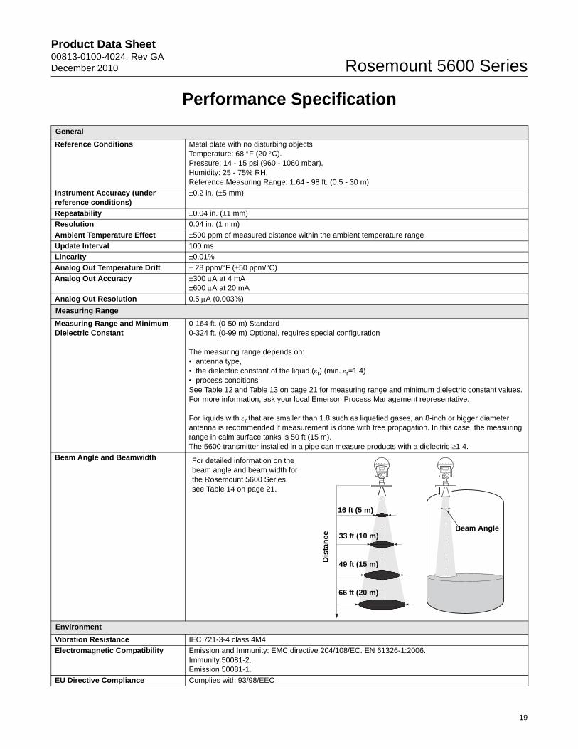
Beam Angle and Beamwidth
Environment
Vibration Resistance IEC 721-3-4 class 4M4
Electromagnetic Compatibility Emission and Immunity: EMC directive 204/108/EC. EN 61326-1:2006.Immunity 50081-2.Emission 50081-1.
EU Directive Compliance Complies with 93/98/EEC
16 ft (5 m)
33 ft (10 m)
49 ft (15 m)
66 ft (20 m)
Beam Angle
Dis
tan
ce
For detailed information on the beam angle and beam width for the Rosemount 5600 Series, see Table 14 on page 21.
19
Product Data Sheet00813-0100-4024, Rev GA
December 2010Rosemount 5600 Series
Transient / Built-in Lightning Protection
EN61326, EN61000-4-5, IEC801-5, level 2 kV
Humidity IEC 60068-2-3
Radio Approvals FCC: K8CPRO, K8CPROXR&TTE: E813268O-CC
Climatic Class/Corrosion Class IEC 68-2-1, IEC 60068-2-52 test KB severity 2
UV Protection ISO 4892-2
Power Supply Fluctuation IEC 92 Part 504 sec. 3.5
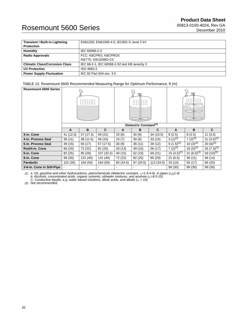
TABLE 12. Rosemount 5600 Recommended Measuring Range for Optimum Performance, ft (m)
Rosemount 5600 Series
Dielectric Constant(1)
(1) A. Oil, gasoline and other hydrocarbons, petrochemicals (dielectric constant, r=1.9-4.0), in pipes (r>1.4)B. Alcohols, concentrated acids, organic solvents, oil/water mixtures, and acetone (r=4.0-10)C. Conductive liquids, e.g. water based solutions, dilute acids, and alkalis (r > 10)
A B C A B C A B C
3-in. Cone 41 (12.5) 57 (17.5) 69 (21) 20 (6) 30 (9) 34 (10.5) 8 (2.5) 8 (2.5) 11 (3.5)
4-in. Process Seal 36 (11) 38 (11.5) 49 (15) 23 (7) 30 (9) 33 (10) 3 (1)(2)
(2) Not recommended.
7 (2)(2) 11 (3.5)(2)
6-in. Process Seal 49 (15) 56 (17) 57 (17.5) 30 (9) 36 (11) 39 (12) 5 (1.5)(2) 10 (3)(2) 20 (6)(2)
Rod/4-in. Cone 66 (20) 72 (22) 82 (25) 43 (13) 49 (15) 56 (17) 7 (2)(2) 16 (5)(2) 25 (7.5)(2)
6-in. Cone 82 (25) 95 (29) 107 (32.5) 49 (15) 62 (19) 69 (21) 15 (4.5)(2) 21 (6.5)(2) 33 (10)(2)
8-in. Cone 99 (30) 131 (40) 131 (40) 72 (22) 82 (25) 95 (29) 21 (6.5) 36 (11) 46 (14)
Parabolic 115 (35) 164 (50) 164 (50) 80 (24.5) 97 (29.5) 113 (34.5) 33 (10) 56 (17) 66 (20)
3-6-in. Cone in Still-Pipe - - - - - - 99 (30) 99 (30) 99 (30)
20
Product Data Sheet00813-0100-4024, Rev GADecember 2010 Rosemount 5600 Series
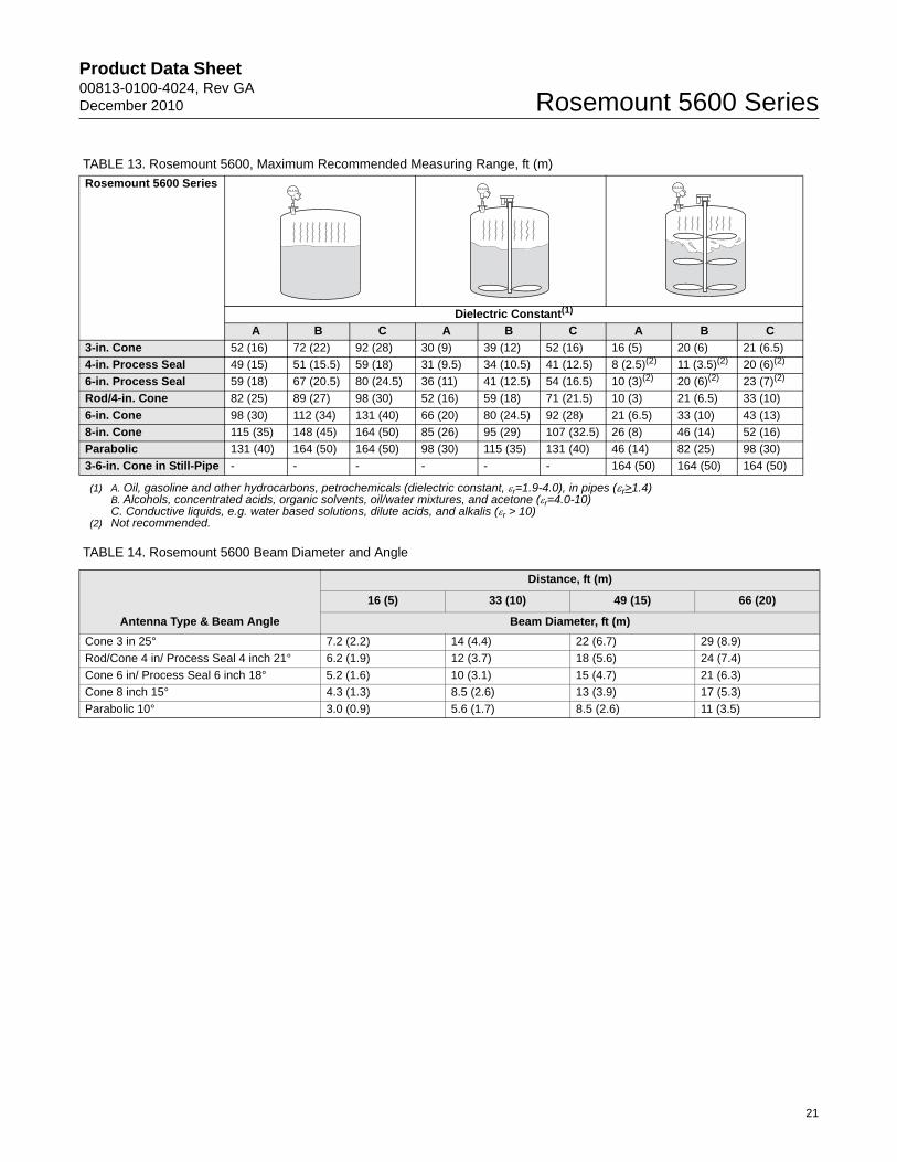
TABLE 14. Rosemount 5600 Beam Diameter and Angle
TABLE 13. Rosemount 5600, Maximum Recommended Measuring Range, ft (m)
Rosemount 5600 Series
Dielectric Constant(1)
(1) A. Oil, gasoline and other hydrocarbons, petrochemicals (dielectric constant, r=1.9-4.0), in pipes (r>1.4)B. Alcohols, concentrated acids, organic solvents, oil/water mixtures, and acetone (r=4.0-10)C. Conductive liquids, e.g. water based solutions, dilute acids, and alkalis (r > 10)
A B C A B C A B C
3-in. Cone 52 (16) 72 (22) 92 (28) 30 (9) 39 (12) 52 (16) 16 (5) 20 (6) 21 (6.5)
4-in. Process Seal 49 (15) 51 (15.5) 59 (18) 31 (9.5) 34 (10.5) 41 (12.5) 8 (2.5)(2)
(2) Not recommended.
11 (3.5)(2) 20 (6)(2)
6-in. Process Seal 59 (18) 67 (20.5) 80 (24.5) 36 (11) 41 (12.5) 54 (16.5) 10 (3)(2) 20 (6)(2) 23 (7)(2)
Rod/4-in. Cone 82 (25) 89 (27) 98 (30) 52 (16) 59 (18) 71 (21.5) 10 (3) 21 (6.5) 33 (10)
6-in. Cone 98 (30) 112 (34) 131 (40) 66 (20) 80 (24.5) 92 (28) 21 (6.5) 33 (10) 43 (13)
8-in. Cone 115 (35) 148 (45) 164 (50) 85 (26) 95 (29) 107 (32.5) 26 (8) 46 (14) 52 (16)
Parabolic 131 (40) 164 (50) 164 (50) 98 (30) 115 (35) 131 (40) 46 (14) 82 (25) 98 (30)
3-6-in. Cone in Still-Pipe - - - - - - 164 (50) 164 (50) 164 (50)
Antenna Type & Beam Angle
Distance, ft (m)
16 (5) 33 (10) 49 (15) 66 (20)
Beam Diameter, ft (m)
Cone 3 in 25° 7.2 (2.2) 14 (4.4) 22 (6.7) 29 (8.9)
Rod/Cone 4 in/ Process Seal 4 inch 21° 6.2 (1.9) 12 (3.7) 18 (5.6) 24 (7.4)
Cone 6 in/ Process Seal 6 inch 18° 5.2 (1.6) 10 (3.1) 15 (4.7) 21 (6.3)
Cone 8 inch 15° 4.3 (1.3) 8.5 (2.6) 13 (3.9) 17 (5.3)
Parabolic 10° 3.0 (0.9) 5.6 (1.7) 8.5 (2.6) 11 (3.5)
21
Product Data Sheet00813-0100-4024, Rev GA
December 2010Rosemount 5600 Series
Physical Specification
Housing and Enclosure
Type Two separate junction boxes that separate electronics from cabling. The transmitter housing can be rotated in any direction, and has interchangeable electronics without opening the tank.
Electrical Connections 3 X 1/2 inch NPT; for cable glands or conduit entriesOptional: 1/2 inch NPT Cable Gland Kit, 1/2 inch NPT / M20 Adapters (Set of 3)Optional remote display (option code R and T): 2 x M20 Entries, 1 x M25 Entry;max. cable length display - radar transmitter: 330 ft (100 m)
The recommended output cabling is a 4-wire, twisted and shielded instrument cable, min. 0.5 mm2 (AWG 20).
Housing Material Permanent moulded cast aluminium, chromed and powder painted
Ingress Protection IP66, IP 67, and NEMA 4
Ingress Protection - Remote Display
IP 67, mounted in separate enclosure with weather/dirt protection cover
Factory Sealed See CSA Approvals information on page 26.
Weight Transmitter Head (TH): 19.8 lb (9.0 kg)
Tank Connection and Antennas
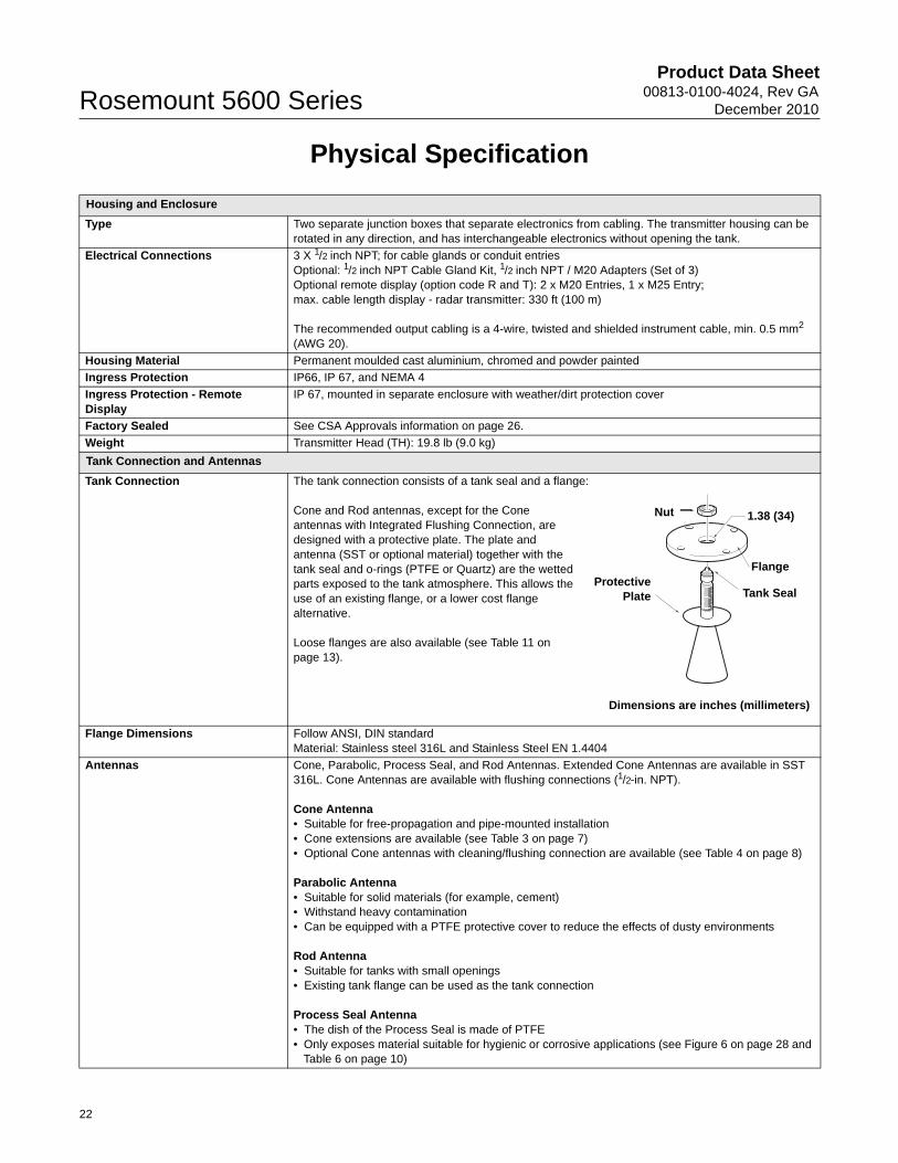
Tank Connection The tank connection consists of a tank seal and a flange:
Cone and Rod antennas, except for the Cone antennas with Integrated Flushing Connection, are designed with a protective plate. The plate and antenna (SST or optional material) together with the tank seal and o-rings (PTFE or Quartz) are the wetted parts exposed to the tank atmosphere. This allows the use of an existing flange, or a lower cost flange alternative.
Loose flanges are also available (see Table 11 on page 13).
Flange Dimensions Follow ANSI, DIN standardMaterial: Stainless steel 316L and Stainless Steel EN 1.4404
Antennas Cone, Parabolic, Process Seal, and Rod Antennas. Extended Cone Antennas are available in SST 316L. Cone Antennas are available with flushing connections (1/2-in. NPT).
Cone Antenna• Suitable for free-propagation and pipe-mounted installation• Cone extensions are available (see Table 3 on page 7)• Optional Cone antennas with cleaning/flushing connection are available (see Table 4 on page 8)
Parabolic Antenna• Suitable for solid materials (for example, cement)• Withstand heavy contamination• Can be equipped with a PTFE protective cover to reduce the effects of dusty environments
Rod Antenna• Suitable for tanks with small openings• Existing tank flange can be used as the tank connection
Process Seal Antenna• The dish of the Process Seal is made of PTFE• Only exposes material suitable for hygienic or corrosive applications (see Figure 6 on page 28 and
Table 6 on page 10)
Nut
Flange
1.38 (34)
Dimensions are inches (millimeters)
ProtectivePlate Tank Seal
22
Product Data Sheet00813-0100-4024, Rev GADecember 2010 Rosemount 5600 Series
Antenna Dimensions Cone Antenna: See Figure 1 on page 27Extended Cone Antenna: See Figure 2 on page 27Cone Antenna with Integrated Flushing Connection: See Figure 3 on page 27Parabolic Antenna: See Figure 4 on page 27Rod Antenna: See Figure 5 on page 28Process Seal Antenna: See Figure 6 on page 28 and Table 17 on page 29
Antenna Weight 3-in. Cone Antenna: 2.20 lb. (1.0 kg)4-in. Cone Antenna: 3.31 lb. (1.5 kg)6-in. Cone Antenna: 4.41 lb. (2.0 kg)8-in. Cone Antenna: 6.61 lb. (3.0 kg)Parabolic Antenna: 17.6 lb. (8.0 kg)Rod Antenna: 4.41 lb. (2.0 kg)4-in. Process Seal Antenna: 4.41 lb. (2.0 kg)6-in. Process Seal Antenna: 5.51 lb. (2.5 kg)
Material Exposed to Tank Atmosphere
Cone Antenna (PTFE sealing)• Antenna: 316L SST (EN1.4404) or Alloy C-22 or Tantalum or Alloy 400• Sealing: PTFE fluoropolymer• O-rings: Viton fluoroelastomer or Kalrez perfluoroelastomerCone Antenna (Quartz sealing)• Antenna: 316L SST (EN1.4404) or Alloy C-22 or Tantalum or Alloy 400• Sealing: Quartz• O-rings: Viton fluoroelastomer or Kalrez perfluoroelastomerParabolic Antenna• 316L SST• FEP/PTFE fluoropolymerRod Antenna• Antenna: 316L SST and PTFE fluoropolymer• Sealing: PTFE fluoropolymer• O-rings: Viton fluoroelastomer or Kalrez perfluoroelastomerProcess Seal Antenna• PTFE fluoropolymer or Al2O3 (Aluminium oxide)
Installation and Mounting Considerations
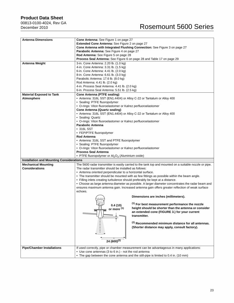
Mechanical Mounting Considerations
The 5600 radar transmitter is easily carried to the tank top and mounted on a suitable nozzle or pipe. The radar transmitter should be installed as follows:• Antenna oriented perpendicular to a horizontal surface.• The transmitter should be mounted with as few fittings as possible within the beam angle. • Filling inlets creating turbulence should preferably be kept at a distance.• Choose as large antenna diameter as possible. A larger diameter concentrates the radar beam and ensures maximum antenna gain. Increased antenna gain offers greater reflection of weak surface echoes.
Pipe/Chamber Installations If used correctly, pipe or chamber measurement can be advantageous in many applications:• Use cone antennas (3 to 6 in.) - not the rod antenna• The gap between the cone antenna and the still-pipe is limited to 0.4 in. (10 mm)
0.4 (10)or more (1)
Dimensions are inches (millimeters).
(1) For best measurement performance the nozzle height should be shorter than the antenna or consider an extended cone (FIGURE 3.) for your current transmitter.
(2) Recommended minimum distance for all antennas. (Shorter distance may apply, consult factory).
24 (600)(2)
23
Product Data Sheet00813-0100-4024, Rev GA
December 2010Rosemount 5600 Series
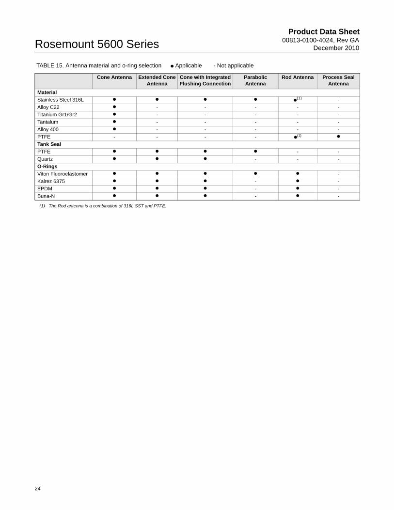
TABLE 15. Antenna material and o-ring selection ● Applicable - Not applicable
Cone Antenna Extended Cone Antenna
Cone with Integrated Flushing Connection
Parabolic Antenna
Rod Antenna Process Seal Antenna
Material
Stainless Steel 316L ● ● ● ● ●(1)
(1) The Rod antenna is a combination of 316L SST and PTFE.
-
Alloy C22 ● - - - - -
Titanium Gr1/Gr2 ● - - - - -
Tantalum ● - - - - -
Alloy 400 ● - - - - -
PTFE - - - - ●(1) ●
Tank Seal
PTFE ● ● ● ● - -
Quartz ● ● ● - - -
O-Rings
Viton Fluoroelastomer ● ● ● ● ● -
Kalrez 6375 ● ● ● - ● -
EPDM ● ● ● - ● -
Buna-N ● ● ● - ● -
24
Product Data Sheet00813-0100-4024, Rev GADecember 2010 Rosemount 5600 Series
Product Certifications
SAFETY NOTE AND SPECIAL CONDITIONS FOR SAFE USE (X-MARKINGS IN ATEX, AND IECEX CERTIFICATES)As light alloys may be used as the enclosure (or other parts) they may be at the accessible surface of this equipment, in the event of rare incidents, ignitions sources due to impact and friction sparks could occur. This shall be considered when the equipment is being installed in locations that specifically require Group II, Category 1G equipment. Under certain extreme circumstances, the non-metallic parts of the equipment may be capable of generating an ignition-capable level or electrostatic charge. Therefore, when used for applications that specifically require Group II, Category 1 equipment, the equipment shall not be installed in a location where the external conditions are conducive to the build-up of electrostatic charge on such surfaces. Additionally, the equipment non-metallic parts shall only be cleaned with a damp cloth
Approved Manufacturing LocationsRosemount Tank Radar AB – Gothenburg, Sweden
EU ConformityComplies with 93/98/EEC. The most recent version of the EC declaration of conformity can be found at www.rosemount.com.
ATEX Directive (94/9/EC)Rosemount Inc. complies with the ATEX Directive.
Ordinary Location Certification for Factory MutualAs standard, the transmitter has been examined and tested to determine that the design meets basic electrical, mechanical, and fire protection requirements by FM, a nationally recognized testing laboratory (NRTL) as accredited by the Federal Occupational Safety and Health Administration (OSHA).
5600 Series Radar Level Transmitter European ATEX Directive InformationThis document lists specific requirements which have to be fulfilled to secure a safe installation and use of 5600 Series Radar Level Transmitter in a hazardous area. Omission may jeopardize safety, and Rosemount will not take any responsibility if requirements as listed below are not fulfilled.
Canadian Registration Number (CRN)The product design of the Cone Antenna has been accepted and registered for use in Canada. CRN: 0F1015.9C
Hazardous Locations Certifications
ATEX Approvals
5600 Series Level TransmitterE1 Certificate Number: Sira 03ATEX1294X
With Intrinsically Safe Outputs (only)
ATEX Marking: II (2) (1) 1/2 GD T85°C
Safety Coding: EEx de [ib] [ia] IIC T6 (-40 °C Tamb +70 °C)
With Non-IS Primary Output and IS Display Output
ATEX Marking: II (1) 1/2 GD T85 °C
Safety Coding: EEx de [ia] IIC T6 (-40 °C Tamb +70 °C)
With Non-IS Primary and/or Non-IS Secondary Outputs
ATEX Marking: II 1/2 GD T85°CSafety Coding: EEx de IIC T6 (-40 °C Tamb +70 °C)
Special Conditions for Safe Use: See first paragraph of the Produce Certifications Chapter
Passive analog output 4-20 mA,
Label identification = HART passive.
Voltage compliance 7-30 V:
Ui = 30 VIi = 200 mACi = 0
Li = 0 Uo = 0Io = 0Um = 250 V
Active analog output 4-20 mA,
Label identification = HART active.
Max load 300:
Uo = 23.1 VIo = 125.7 mAPo = 0.726 WCext =0.14 FLext = 2.2 mHCi = 0Li = 0
FOUNDATION Fieldbus,Label identification = FOUNDATION fieldbus.
Ui = 30 VIi = 300 mAPi = 1.3 WCi = 0 Li = 0
2210 Display UnitCertificate Number: Sira 00ATEX2062
Without Temperature Inputs
ATEX Marking: II 2 G
Safety Coding: EEx ib IIC T4 (-40 °C Tamb +70 °C)
With Temperature Inputs
ATEX Marking: II 2 (1) G
Safety Coding: EEx ib [ia] IIC T4 (-40 °C Tamb +70 °C)
25
Product Data Sheet00813-0100-4024, Rev GA
December 2010Rosemount 5600 Series
Factory Mutual (FM) Approvals
5600 Series Level TransmitterE5 Certificate Number: 4D5A9.AX
With Intrinsically safe outputs(all versions except those listed below)
Explosion proof with IS outputs for HAZLOC
Class I, Division 1, Group A, B, C, and D, T6
Max operating temperature +70 °C
Dust ignition proof for use in Class II/III, Division 1, Groups E, F, and G, T5.
Use conductors rated at least 85 °C
Shall be installed in accordance with System control drawing 9150074-994.
With Non-IS Secondary Outputs (codes 1 and 3)
Explosion proof
Class I, Division 1, Group A, B, C, and D, T6
Max operating temperature +70 °C
Dust ignition proof for use in Class II/III, Division 1, Groups E, F, and G, T5.
Use conductors rated at least 85 °C
2210 Display UnitCertificate Number: 3008356
All Versions
Intrinsic Safe for HAZLOC
Class I, Division 1, Group A, B, C, and D T4
Max operating temperature +70 °C
Shall be installed in accordance with System control drawing 9150074-997.
Canadian Standards Association (CSA Approvals)
5600 Series Level TransmitterE6 Certificate Number: 2003.153280-1346169
With Non-IS Primary and/or Secondary Outputs
Explosion proof Ex de IIC T6
Shall be installed in accordance with System control drawing 9150074-937.
Factory seal, conduit seal not required.
With IS Display Outputs, IS Primary and/or Secondary Outputs
Explosion proof Ex de [ib/ia] IIC T6
Shall be installed in accordance with System control drawing 9150074-939.
Factory seal, conduit seal not required.
2210 Display UnitCertificate Number: 2003.153280-1346165
Without Temperature Inputs
Intrinsically safe EEx ib IIC T4 (-40 °C Tamb +70 °C) With Temperature Inputs
Intrinsically safe EEx ib [ia] IIC T4 (-40 °C Tamb +70 °C)
Shall be installed in accordance with System control drawing 9150074-944.
IECEx Approvals
5600 Series Level Transmitter
E7 Certificate Number: IECEx SIR 05.0024X
With Intrinsically Safe Outputs (only)
Safety Coding: Ex de [ib] [ia] IIC T6 tD A20 IP65 T85 °C(-40 °C Tamb +70 °C)
With Non-IS Primary Output and IS Display Output
Safety Coding: Ex de [ia] IIC T6 tD A20 IP65 T85 °C(-40 °C Tamb +70 °C)
With Non-IS Primary and/or Non-IS Secondary Outputs
Safety Coding: Ex de IIC T6 tD A20 IP65 T85 °C(-40 °C Tamb +70 °C)
Passive analog output 4-20 mA,
Label identification = HART passive.
Voltage compliance 7-30 V:
Ui = 30 VIi = 200 mACi = 0 Li = 0 Uo = 0 Io = 0 Um = 250 V rms
Active analog output 4-20 mA,
Label identification = HART active.
Max load 300 :
Uo = 23.1 VIo = 125.7 mAPo = 0.726 WCo = 0.14 FLo = 2.2 mHCi = 0 Li = 0
FOUNDATION Fieldbus,
Label identification = FOUNDATION fieldbus.
Ui = 30 VIi = 300 mAPi = 1.3 WCi = 0 Li = 0
Conditions of Certification: See first paragraph of the Produce Certifications Chapter
2210 Display UnitCertificate Number: IECEx SIR 05.0021
Without Temperature Inputs
Safety Coding: Ex ib IIC T4 (-40 °C Tamb +70 °C)
With Temperature Inputs
Safety Coding: Ex ib [ia] IIC T4 (-40 °C Tamb +70 °C)
Overfill Protection
Cert no: Z-65.16-417
U1 TÜV-tested and approved for overfill protection according to the German WHG regulations
26
Product Data Sheet00813-0100-4024, Rev GADecember 2010 Rosemount 5600 Series
Dimensional Drawings
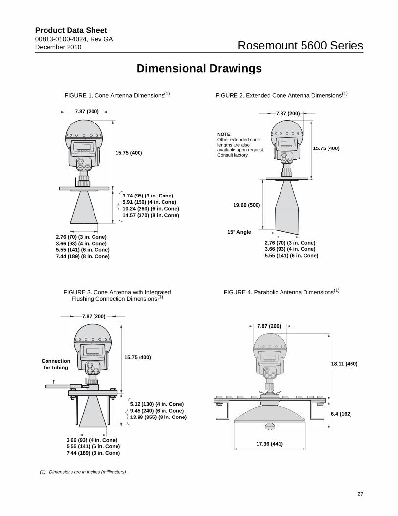
FIGURE 1. Cone Antenna Dimensions(1)
(1) Dimensions are in inches (millimeters)
FIGURE 2. Extended Cone Antenna Dimensions(1)
FIGURE 3. Cone Antenna with Integrated Flushing Connection Dimensions(1)
FIGURE 4. Parabolic Antenna Dimensions(1)
7.87 (200)
2.76 (70) (3 in. Cone)3.66 (93) (4 in. Cone)5.55 (141) (6 in. Cone)7.44 (189) (8 in. Cone)
3.74 (95) (3 in. Cone)5.91 (150) (4 in. Cone)10.24 (260) (6 in. Cone)14.57 (370) (8 in. Cone)
15.75 (400)
7.87 (200)
2.76 (70) (3 in. Cone)3.66 (93) (4 in. Cone)5.55 (141) (6 in. Cone)
15° Angle
19.69 (500)
15.75 (400)
NOTE: Other extended cone lengths are also available upon request. Consult factory.
7.87 (200)
3.66 (93) (4 in. Cone)5.55 (141) (6 in. Cone)7.44 (189) (8 in. Cone)
5.12 (130) (4 in. Cone)9.45 (240) (6 in. Cone)13.98 (355) (8 in. Cone)
15.75 (400)Connection for tubing
7.87 (200)
18.11 (460)
6.4 (162)
17.36 (441)
27
Product Data Sheet00813-0100-4024, Rev GA
December 2010Rosemount 5600 Series
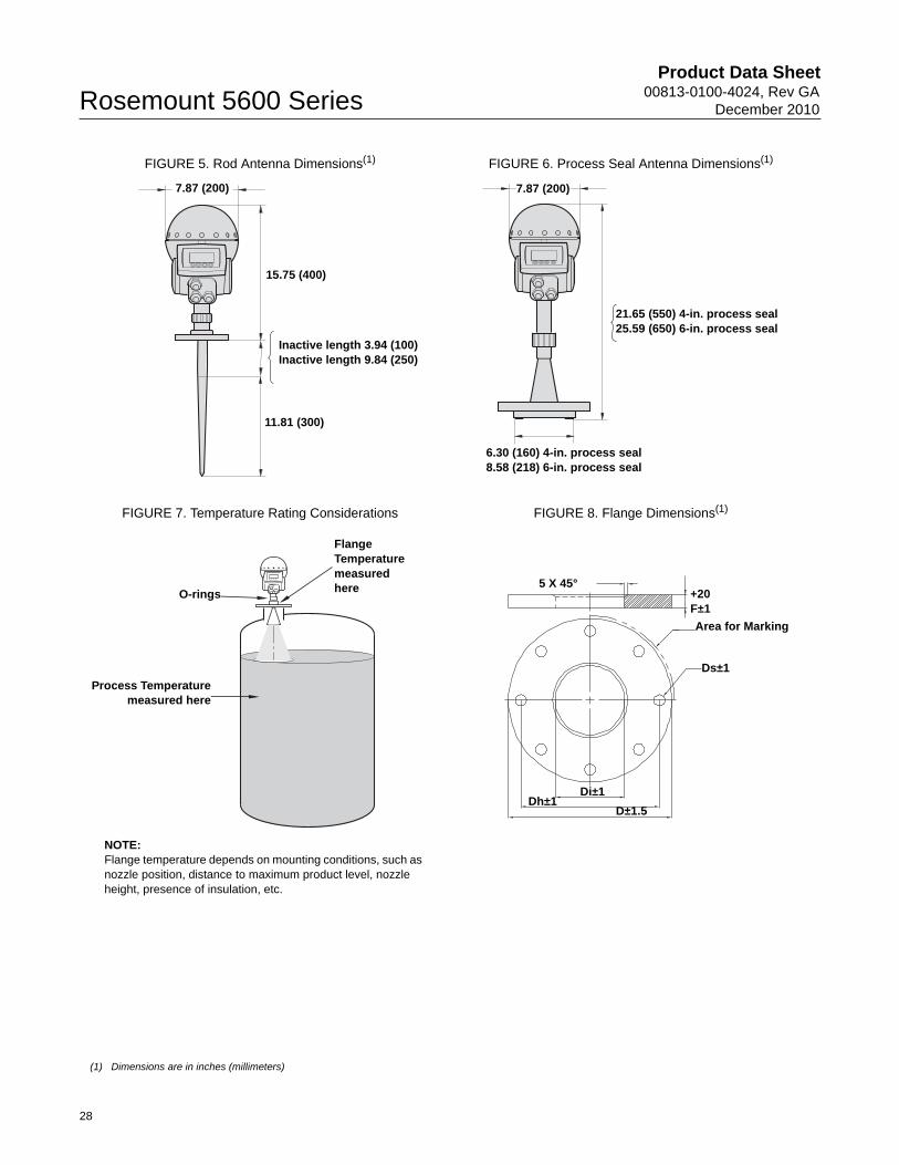
FIGURE 5. Rod Antenna Dimensions(1) FIGURE 6. Process Seal Antenna Dimensions(1)
FIGURE 7. Temperature Rating Considerations FIGURE 8. Flange Dimensions(1)
(1) Dimensions are in inches (millimeters)
7.87 (200)
15.75 (400)
Inactive length 3.94 (100)Inactive length 9.84 (250)
11.81 (300)
7.87 (200)
21.65 (550) 4-in. process seal25.59 (650) 6-in. process seal
6.30 (160) 4-in. process seal8.58 (218) 6-in. process seal
Flange Temperature measured here
Process Temperaturemeasured here
NOTE:Flange temperature depends on mounting conditions, such as nozzle position, distance to maximum product level, nozzle height, presence of insulation, etc.
O-rings
Area for Marking
Ds±1
Di±1Dh±1
D±1.5
5 X 45°+20F±1
28
Product Data Sheet00813-0100-4024, Rev GADecember 2010 Rosemount 5600 Series
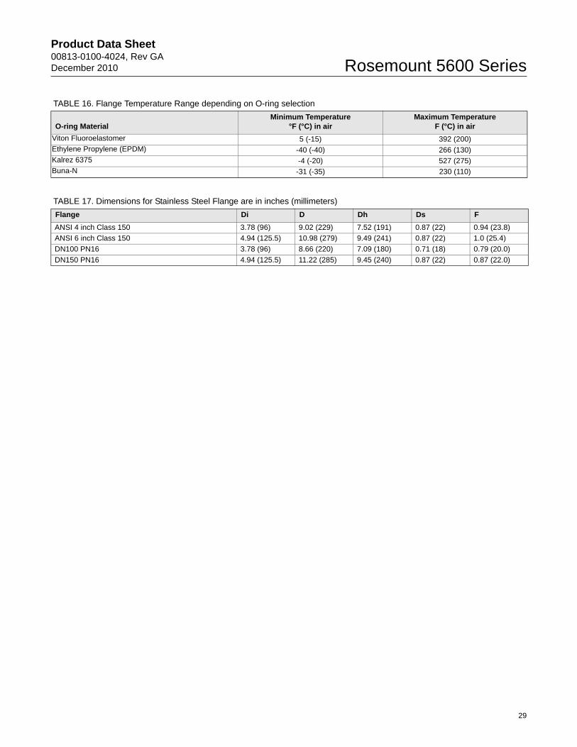
TABLE 16. Flange Temperature Range depending on O-ring selection
O-ring MaterialMinimum Temperature
°F (°C) in airMaximum Temperature
F (°C) in air
Viton Fluoroelastomer 5 (-15) 392 (200)Ethylene Propylene (EPDM) -40 (-40) 266 (130)Kalrez 6375 -4 (-20) 527 (275)Buna-N -31 (-35) 230 (110)
TABLE 17. Dimensions for Stainless Steel Flange are in inches (millimeters)
Flange Di D Dh Ds F
ANSI 4 inch Class 150 3.78 (96) 9.02 (229) 7.52 (191) 0.87 (22) 0.94 (23.8)
ANSI 6 inch Class 150 4.94 (125.5) 10.98 (279) 9.49 (241) 0.87 (22) 1.0 (25.4)
DN100 PN16 3.78 (96) 8.66 (220) 7.09 (180) 0.71 (18) 0.79 (20.0)
DN150 PN16 4.94 (125.5) 11.22 (285) 9.45 (240) 0.87 (22) 0.87 (22.0)
29
00813-0100-4024 Rev GA, 12/10
Standard Terms and Conditions of Sale can be found at www.rosemount.com\terms_of_saleThe Emerson logo is a trademark and service mark of Emerson Electric Co.Rosemount and the Rosemount logotype are registered trademarks of Rosemount Inc.Fisher is a mark owned by Fisher Controls International LLC, a member of the Emerson Process Management business division of Emerson Electric Co.PlantWeb is a registered trademark of the Emerson Process Management group of companies.HART and WirelessHART are registered trademarks of the HART Communication Foundation.Viton, and Kalrez are registered trademarks of Du Pont Performance Elastomers.FOUNDATION is a trademark of the Fieldbus Foundation.DeltaV is a trademark of Emerson Process Management group of companies.Eurofast and Minifast are registered trademarks of Turck Inc.Masoneilan is a registered trademark of Dresser Inc.All other marks are the property of their respective owners.© 2010 Rosemount Inc. All rights reserved.
Product Data Sheet00813-0100-4024, Rev GA
December 2010Rosemount 5600 Series
Emerson Process Management Rosemount Measurement8200 Market BoulevardChanhassen MN 55317 USATel (USA) 1 800 999 9307Tel (International) +1 952 906 8888Fax + 1 952 949 7001
Europe Process ManagementBlegistrasse 23P.O. Box 1046CH 6341 BaarSwitzerlandTel +41 (0) 41 768 6111Fax +41 (0) 41 768 6300
Emerson Process Management AsiaPacific Pte Ltd1 Pandan CrescentSingapore 128461Tel +65 6777 8211Fax +65 6777 0947Service Support Hotline: +65 6770 8711Email: [email protected]
Emerson FZEP.O. Box 17033Jebel Ali Free ZoneDubai UAETel +971 4 811 8100Fax +971 4 886 5465
Rosemount Level Solutions
Emerson provides a complete range of Rosemount products for level measurement applications.
Vibrating Fork Switches – Point Level Detection
For high and low alarms, overfill protection, pump control, including wide pressure and temperature requirements, and hygienic applications. Flexible mounting. Immune to changing process conditions and suitable for most liquids. The product line consists of:
• Rosemount 2160 Wireless
• Rosemount 2130 Enhanced
• Rosemount 2120 Full-featured
• Rosemount 2110 Compact
Differential Pressure – Level or Interface Measurement
Flexible mounting for liquid tank levels, including those with wide temperature and pressure requirements. Can be isolated by valves. Unaffected by: vapor space changes, surface conditions, foam, corrosive fluids, internal tank equipment. Optimize performance with direct mount, Tuned-System Assemblies:
• Rosemount DP Level Transmitters and Remote Seals
• Rosemount 3051S_L, 3051L, and 2051L Liquid Level Transmitters
Ultrasonic – Level Measurement
Top mounted, non-contacting for simple tank and open air level measurements. Unaffected by fluid properties such as: density, viscosity, dirty coating, and corrosiveness. Appropriate for routine applications outside of explosion proof areas.The product line consists of:
• Rosemount 3100 Series Ultrasonic Process Level Transmitters
Guided Wave Radar – Level and Interface Measurement
Top mounted, direct level and interface measurement of liquids or solids, including those with wide temperature and pressure requirements. Unaffected by changing process conditions. Good fit for small spaces and easy swap for older technologies.The product line consists of:
• Rosemount 5300 Series – Accurate, superior performance transmitter in most applications including process vessels and control
• Rosemount 3300 Series – Versatile and easy-to-use transmitter in most liquid storage and monitoring applications
Non-contacting Radar – Level Measurement
Top mounted, direct level measurement for liquids or solids, including those with wide temperature and pressure requirements. Can be isolated by valves. Unaffected by changing process conditions. Good for dirty, coating, and corrosive applications.The product line consists of:
• Rosemount 5400 Series – Accurate, superior performance 2-wire transmitters for most liquid level applications and process conditions
• Rosemount 5600 Series – 4-wire transmitters with maximum sensitivity and performance for solids, challenging reactors, rapid level changes and excessive process conditions
Chambers for Process Level Instrumentation
• Rosemount 9901 – High quality chambers for external mounting of level measurement and control instrumentation on process vessels
A.P.O. - ELMOS v.o.s., Pražská 90, 509 01 Nová Paka, Tel.: +420 493 504 261, Fax: +420 493 504 257, E-mail: [email protected], Internet: www.apoelmos.cz