ENHANCE THE LINK BETWEEN REMOTE SENSING AND IN-SITU OBSERVATION

Technical Note
In Situ Observation of Mechanical Testing at the Nanoscale

2
In Situ Observation of Mechanical Testing at the Nanoscale
Author: Carl Zeiss X-ray Microscopy Pleasanton, California
Date: March 2015
X-ray microscopy (XRM) enables nondestructive 3D investigation of a variety of samples across multiple length scales.
By adapting advanced X-ray optics from synchrotron developments, 3D X-ray tomography with resolution down to
50 nm is now available in the laboratory. As a nondestructive technique, X-ray tomography uniquely enables 4D studies
by observing 3D structure at multiple points in time and under varying realistic conditions. These conditions can
include a variety of external stimuli, including mechanical loads. In this Technical Note we introduce the concept of
in situ mechanical testing integrated in nanoscale XRM. This approach is complementary to established ex situ or
in situ testing methods in SEM or TEM, but covers a unique 3D length scale, offering new opportunities to connect
small scale evolution processes with those observed in micron scale XRM and bulk material testing. This connection
of micro and macro deformation behavior, with direct 3D visualization, has promising applications covering a variety
of materials from metals to biomaterials to thin coatings. Xradia Ultra Load Stage, a new nanomechanical test stage,
is now available for integration into ZEISS Xradia Ultra, the only nanoscale XRM available for the laboratory.
Nanomechanical testing seeks to answer the question:
How does a material yield, deform, and fail on small scales?
By combining with in situ 3D observation, we now seek to
answer the next question: how do these mechanisms vary locally
within the sample, and what role does the microstructure play
in determining the bulk properties and behavior?
This broad concept can be further refined with several more
targeted questions:
• How is the behavior of individual micro- and nano-features
such as struts, films, “walls”, particles, etc. different from
the collective bulk? How does this limit the interpretation
of material properties from a purely geometric perspective
based on simple morphological properties like porosity,
surface area, etc.?
• What effects do these features have on the local deformation
of a material? For example, do some locations display brittle
behavior and others ductile? Do these events occur with
sufficient frequency or prevalence that the effects cascade
up to larger length scales?
• In terms of engineering a material with desirable properties
(modulus, hardness, toughness, etc.) are some defects and
features acceptable and others not?
Investigating Under Load
To investigate the deformation and possible structural failure
under various loading conditions, a nanomechanical testing
rig has been designed that can be easily configured by the
user to enable three different operating modes—compression,
tension,and nanoindentation. Xradia Ultra Load Stage operates
on samples of sizes typical of the nanoscale X-ray microscope,
on the order of a 10-100 micron diameter cross section.
This length scale simultaneously satisfies two experimental
constraints by:
1) providing optimal X-ray attenuation characteristics for a
wide variety of sample types, and
2) effectively connecting the length scales of material
deformation spanning resolutions from tens of nanometers
up to sample sizes approaching bulk material response.
Technical Note
3
Technical Note
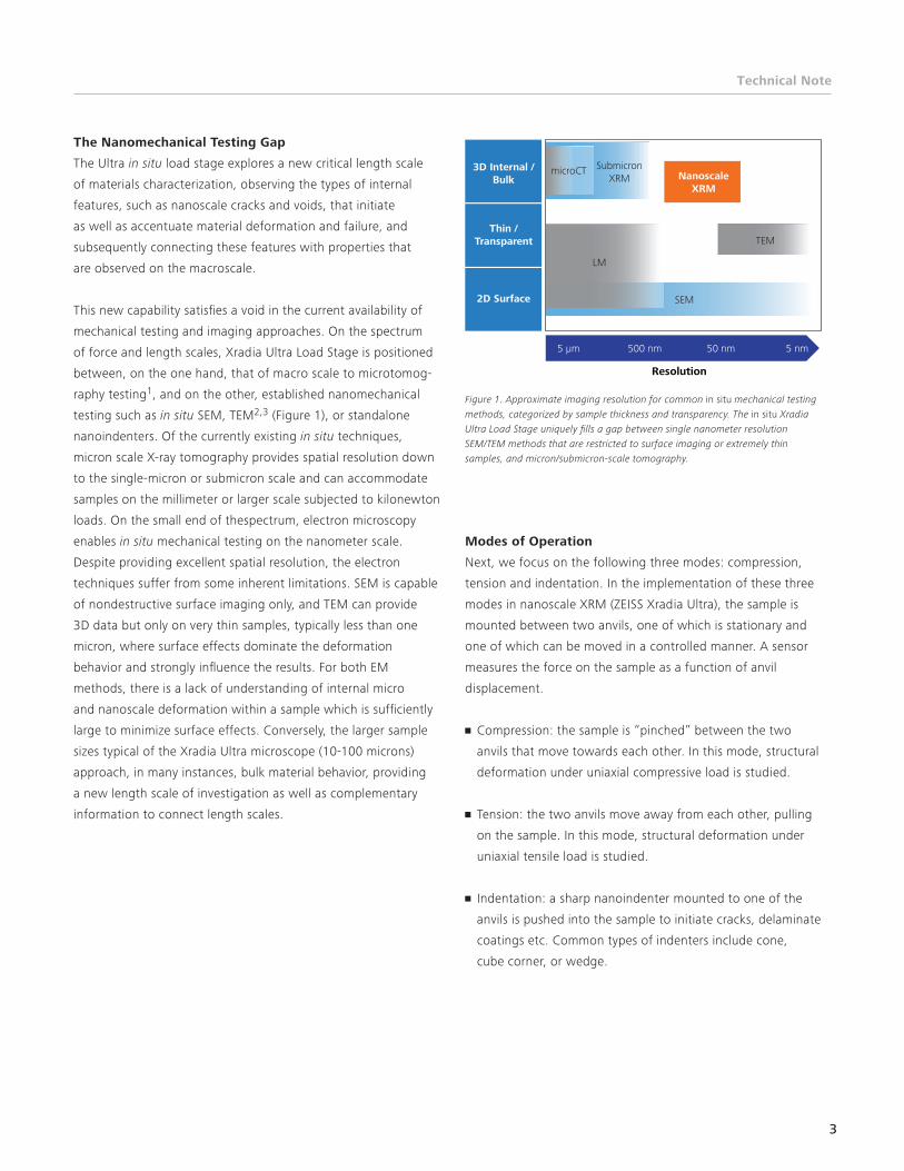
The Nanomechanical Testing Gap
The Ultra in situ load stage explores a new critical length scale
of materials characterization, observing the types of internal
features, such as nanoscale cracks and voids, that initiate
as well as accentuate material deformation and failure, and
subsequently connecting these features with properties that
are observed on the macroscale.
This new capability satisfies a void in the current availability of
mechanical testing and imaging approaches. On the spectrum
of force and length scales, Xradia Ultra Load Stage is positioned
between, on the one hand, that of macro scale to microtomog-
raphy testing1, and on the other, established nanomechanical
testing such as in situ SEM, TEM2,3 (Figure 1), or standalone
nanoindenters. Of the currently existing in situ techniques,
micron scale X-ray tomography provides spatial resolution down
to the single-micron or submicron scale and can accommodate
samples on the millimeter or larger scale subjected to kilonewton
loads. On the small end of thespectrum, electron microscopy
enables in situ mechanical testing on the nanometer scale.
Despite providing excellent spatial resolution, the electron
techniques suffer from some inherent limitations. SEM is capable
of nondestructive surface imaging only, and TEM can provide
3D data but only on very thin samples, typically less than one
micron, where surface effects dominate the deformation
behavior and strongly influence the results. For both EM
methods, there is a lack of understanding of internal micro
and nanoscale deformation within a sample which is sufficiently
large to minimize surface effects. Conversely, the larger sample
sizes typical of the Xradia Ultra microscope (10-100 microns)
approach, in many instances, bulk material behavior, providing
a new length scale of investigation as well as complementary
information to connect length scales.
Modes of Operation
Next, we focus on the following three modes: compression,
tension and indentation. In the implementation of these three
modes in nanoscale XRM (ZEISS Xradia Ultra), the sample is
mounted between two anvils, one of which is stationary and
one of which can be moved in a controlled manner. A sensor
measures the force on the sample as a function of anvil
displacement.
• Compression: the sample is “pinched” between the two
anvils that move towards each other. In this mode, structural
deformation under uniaxial compressive load is studied.
• Tension: the two anvils move away from each other, pulling
on the sample. In this mode, structural deformation under
uniaxial tensile load is studied.
• Indentation: a sharp nanoindenter mounted to one of the
anvils is pushed into the sample to initiate cracks, delaminate
coatings etc. Common types of indenters include cone,
cube corner, or wedge.
Figure 1. Approximate imaging resolution for common in situ mechanical testing methods, categorized by sample thickness and transparency. The in situ Xradia Ultra Load Stage uniquely fills a gap between single nanometer resolution SEM/TEM methods that are restricted to surface imaging or extremely thin samples, and micron/submicron-scale tomography.
2D Surface
3D Internal /Bulk
Thin /Transparent
5 µm 500 nm 50 nm 5 nm
Resolution
LM
TEM
microCT SubmicronXRM
SEM
NanoscaleXRM

4
Technical Note
Compression
In situ nanomechanical compression combined with X-ray to-
mography can be used to observe the deformation of materials
under compressive load. This type of mechanical test has been
commonly used in ex situ applications to study the behavior of
samples such as metal pillars and porous foams, but a direct 3D
image of the deformation process on this length scale has not
been previously available. This has left a number of unanswered
questions in terms of the relevant local mechanisms. Do micro
and nanoscale features undergo uniaxial compression in a similar
manner to the bulk sample, or are there local buckling/yielding
events? Likely there is varying behavior especially for small, high
aspect ratio features such as struts or pore walls. Pores of differ-
ent sizes may also yield at different rates. Furthermore, if there
are anisotropic structures what is the relationship between load-
ing direction, deformation direction, and feature orientation?
These types of structures could have implications for the lateral
expansion of the sample orthogonally to the loading direction.
And finally, how do these microstructures affect relaxation after
load? It is now possible to observe if certain features relax
elastically, while others remain permanently deformed.
Tension
Tensile testing can reveal an additional wealth of information
about a sample’s deformation and failure mechanisms, including
critical properties like elastic modulus and tensile yield strength.
While these properties can be traced back to atomistic level
deformation events in the form of dislocations, at what level
do these processes combine in a fashion that dictates bulk
behavior? Xradia Ultra Load Stage can uniquely help address
this question by operating at an intermediate length between
atomistic information and bulk properties; at this scale nano/
microstructural features can constitute critical locations where
isolated deformation events likely begin to occur on a length
scale capable of propagating up to macro-level response.
In a tensile scenario, these types of critical locations include
micro-voids, where increased loading can lead to growth and
coalescence of neighboring voids, as well as possible crack
initiation sites in high stress regions of surrounding material.
It can also include thin and anisotropic features such as struts
and fibers which can undergo local rupture and failure at differ-
ent rates and under different loading than larger domains. It is
also possible, particularly in the case of composite materials, to
consider regions of varying chemistry or grain structure, resulting
Compression
Top Anvil
X-rayBeam Path
Sample
Bottom Anvil
Sample Rotationfor Tomography
Top Anvil
X-rayBeam Path
Sample
Bottom Anvil
Sample Rotationfor Tomography
Top Anvil
X-rayBeam Path
Sample
Bottom Anvil
Sample Rotationfor Tomography
Top Anvil
X-rayBeam Path
Sample
Bottom Anvil
Sample Rotationfor Tomography
Top Anvil
X-rayBeam Path
Sample
Bottom Anvil
Sample Rotationfor Tomography
Top Anvil
X-rayBeam Path
Sample
Bottom Anvil
Sample Rotationfor Tomography
Tension

5
Technical Note
possibly in effects such as locally ductile expansion in one region,
but locally brittle failure in a neighboring region. These detailed
microstructural effects could indeed have implications for a wide
variety of sample types including the life sciences (bone, natural
fibers, animal setae, hair), geosciences (mechanics of rock and
ore), and materials science (metals, polymers, ceramics, MEMS).
Indentation
Nanoindentation offers the opportunity to study very isolated
deformation and failure events surrounding the indentation site.
This type of test has a number of distinct advantages, including
the study of samples with small linear dimensions, such as coat-
ings and layered structures. In addition, the capability to apply
the load in a carefully isolated manner enables the user to locally
select the position where failure should initiate. For example, in
a composite material consisting of a matrix and distributed inclu-
sion particles, indentation provides the researcher with the abili-
ty to initiate deformation of the matrix either in close proximity
or extended distance from an inclusion. In a general sense, the
indentation can be targeted near particular features of interest,
like voids, micro-channels, or interfaces. The exact location in
which force is applied often has great impact on such phenome-
na as crack initiation, growth, and coalescence.
By combining the indentation test with the 3D imaging capability
of nanoscale X-ray microscopy, it is possible to observe these
processes as they occur not only on the surface but also within
the sample interior. For thin films and coatings, this can provide
insight into localized delamination processes that occur at
sub-surface interfaces. For a variety of additional sample types
such as metals, concrete building materials, bone, and teeth,
it reveals the impacts that internal heterogeneities and defects
near the indentation site have on the deformation and failure
of the overall sample.
Practical Considerations
Sample sizes for the described methodology are on the order
of tens to hundreds of microns, and based on the Young’s mod-
ulus for elastic deformation over a range of sample types, such
sizes typically require forces in the millinewton to single Newton
range to produce deformation on the micron scale. To track this
behavior quantitatively during loading, load-displacement curves
are acquired to relate the applied force to the deformation or
damage events directly observed from the imaging.
As another consideration, data acquisition times in lab based
nanoscale XRM are on the order of hours for 3D tomographic
datasets. Therefore, real time observation of dynamic processes
is not practical. Instead, nanoscale XRM lends itself to so-called
“interrupted 4D” experiments, where 3D datasets are acquired
at multiple, discrete steps when the loading condition is held
static. The in situ configuration is still critical for this type of
measurement as the load must be maintained during imaging
to properly represent deformation processes such as the opening
of crack tips. To advance scientific understanding during dynamic
loading between tomography acquisitions, the sample can be
monitored in 2D radiography mode on the time scale of seconds
to minutes.
Lastly, while X-ray tomography ideally is performed over a
rotation range of at least +/- 90 degrees, nanomechanical testing
requires a structurally rigid connection of the two anvils between
which the sample is mounted. The lack of mechanically strong
but X-ray transparent materials in the X-ray energy range of
interest (5.4 or 8 keV in currently available instruments) requires
a narrow but strong support post. This limits the angular range
for tomographic data acquisition to about +/- 70 degrees.
Top Anvil
X-rayBeam Path
Sample
Bottom Anvil
Sample Rotationfor Tomography
Top Anvil
X-rayBeam Path
Sample
Bottom Anvil
Sample Rotationfor Tomography
Top Anvil
X-rayBeam Path
Sample
Bottom Anvil
Sample Rotationfor Tomography
Indentation

6
Technical Note
Demonstration
The concept of in situ nanomechanical testing in XRM is demon-
strated here on two types of materials intended to indicate the
possible range of applications. A compression experiment was
performed on a porous elastomer as shown in Figure 2. The
sample is mounted on the bottom anvil (not visible) and occupies
most of the field of view, while the stationary top anvil is also
visible at the top of the field of view. The three panels display
the results of three separate tomography scans conducted be-
fore, during, and after a compressive loading process. Panel
(a) depicts the original, uncompressed sample. In panel (b), the
sample has been moved vertically upward, putting the sample
in contact with the top anvil causing compression. The loading
was maintained in this state during the collection of the tomog-
raphy. After tomography, the sample was moved back down to
the original position to remove the compressive force. A third
tomography, depicted in panel (c), reveals the final deformation
of the sample after removal of the applied load, suggesting
permanent changes of the microstructure.
In a second experiment, nanoindentation was performed on a
sample of dentin. Dentin is a natural microstructured composite
material found in teeth, serving functions of transport, cell
communication, and structural reinforcement. The material
displays excellent mechanical and fracture toughness, making
it a prime candidate for biomimetic engineering. In this work,
in situ X-ray microscopy was performed with Zernike phase
contrast to observe both the sample and the diamond indenter
tip. Evidence of the internal tubular dentin structure, which
is hypothesized to be responsible for many of the material’s
impressive properties, is also visible from the surface renderings.
Two data sets were collected, first at light load and second after
partial fracture initiated by cracking around the indenter tip, as
shown in Figure 3 below. Investigation of the internal structure
can reveal where these cracks initiate and propagate relative
to the tubules, helping to explain why bulk dentin displays
such exceptional mechanical toughness.
Figure 3. Nanoindentation of dentin. (a) 3D rendering of dentin sample before cracking. The indenter tip is visible above the sample. (b) 3D rendering of the same sample after the indenter tip has been driven into the sample and a piece of dentin has fractured off. (c) Force-displacement curve. The fracture event is clearly visible. Courtesy The University of Manchester.
Figure 2. Compressive loading of a porous elastomer. (a) Uncompressed, (b) Compressed, (c) Decompressed
10 µm
10 µm
a b
a b c

7
Technical Note
Outlook
In situ mechanical testing in a nanoscale X-ray microscope
applies to a wide range of in terests, covering both engineered
and natural materials. Many such materials display hierarchical
structures, with the behavior at the bulk scale intimately linked
to the structure and properties of multiple smaller scales.
Nanoscale XRM, sitting in the unique nanometer to micron
nondestructive 3D imaging regime, has the potential to help link
observations across this vast range of scales, and complement
existing methods including in situ SEM, TEM, and micron scale
XRM. Specifically, Xradia Ultra Load Stage, capable of compres-
sion, tension, and indentation loading, offers new capabilities
to observe internal processes such as elastic and plastic deforma-
tion, crack initiation and propagation, and sur face delamination
down to the 50 nm scale. While not an inclu sive list, this is
envisioned to have strong applications in such fields as high
strength alloys, coatings, fiber composites, bioma terials,
building materials, and engineered foams.
References:
[1] BM Patterson, et al., “Measure of Morphological and Performance Properties in Polymeric Silicone Foams by X-ray Tomography,” J Mater Sci 48 (2013):
1986-1996. DOI: 10.1007/s10853-012-6965-2
[2] W Kang, et al., “In-Situ Uniaxial Mechanical Testing of Small Scale Materials--A Review,” Nanoscience and Nanotechnology Letters 2 (2010): 282-287.
DOI: 10.1166/nnl.2010.1107
[3] MA Haque and MTA Saif, “In-situ Tensile Testing of Nano-scale Specimens in SEM and TEM,” Experimental Mechanics 42 (2002): 123-128.
DOI: 10. 1007/BF02411059

EN_4
4_01
3_01
9 C
Z 03
-201
5 | D
esig
n, s
cope
of
deliv
ery
and
tech
nica
l pro
gres
s su
bjec
t to
cha
nge
with
out
notic
e. |
© C
arl Z
eiss
Mic
rosc
opy
Gm
bH
Carl Zeiss Microscopy GmbH 07745 Jena, Germany [email protected] www.zeiss.com/microscopy
www.zeiss.com/xrm