Title In situ observation of austenite coarsening induced ...
10
Title In situ observation of austenite coarsening induced by massive- like transformation during solidification in Fe‒C alloys Author(s) Yasuda, Hideyuki; Suga, Takeru; Ichida, Kodai; Narumi, Taka; Morishita, Kohei Citation IOP Conference Series: Materials Science and Engineering (2020), 861 Issue Date 2020 URL http://hdl.handle.net/2433/261808 Right Content from this work may be used under the terms of the Creative Commons Attribution 3.0 licence. Any further distribution of this work must maintain attribution to the author(s) and the title of the work, journal citation and DOI. Type Journal Article Textversion publisher Kyoto University
Transcript of Title In situ observation of austenite coarsening induced ...

Title In situ observation of austenite coarsening induced by massive-like transformation during solidification in Fe‒C alloys
Author(s) Yasuda, Hideyuki; Suga, Takeru; Ichida, Kodai; Narumi, Taka;Morishita, Kohei
Citation IOP Conference Series: Materials Science and Engineering(2020), 861
Issue Date 2020
URL http://hdl.handle.net/2433/261808
Right
Content from this work may be used under the terms of theCreative Commons Attribution 3.0 licence. Any furtherdistribution of this work must maintain attribution to theauthor(s) and the title of the work, journal citation and DOI.
Type Journal Article
Textversion publisher
Kyoto University

IOP Conference Series: Materials Science and Engineering
PAPER • OPEN ACCESS
In situ observation of austenite coarsening inducedby massive-like transformation during solidificationin Fe–C alloysTo cite this article: H Yasuda et al 2020 IOP Conf. Ser.: Mater. Sci. Eng. 861 012051
View the article online for updates and enhancements.
Recent citationsTransformation from Ferrite to Austeniteduring/after Solidification in Peritectic SteelSystems: an X-ray Imaging StudyHideyuki Yasuda et al
-
This content was downloaded from IP address 130.54.110.23 on 02/03/2021 at 02:38

Content from this work may be used under the terms of the Creative Commons Attribution 3.0 licence. Any further distributionof this work must maintain attribution to the author(s) and the title of the work, journal citation and DOI.
Published under licence by IOP Publishing Ltd
MCWASP XV 2020
IOP Conf. Series: Materials Science and Engineering 861 (2020) 012051
IOP Publishing
doi:10.1088/1757-899X/861/1/012051
1
In situ observation of austenite coarsening induced by
massive-like transformation during solidification in Fe–C
alloys
H Yasuda1, T Suga1, K Ichida1, T Narumi1 and K Morishita1, 2
1 Department of Materials Science and Engineering, Kyoto University, Sakyo, Kyoto
606-8501, Japan 2 Department of Materials Science and Engineering, Kyushu University, Nishiku,
Fukuoka, 819-0395 Japan
E-mail: [email protected]
Abstract. A massive-like transformation, in which δ-ferrite massively transforms to γ-austenite
in the solid state, was examined by time-resolved X-ray imaging and X-ray diffractometry on a
four-dimensional–computed tomography setup. In the unidirectional solidification of a
hyperperitectic steel (0.3 mass% C) at 50 μm/s, δ dendrites, fine γ grains that are produced
through the massive-like transformation, and coarse γ grains grow together in the steady state.
The massive-like transformation occurred commonly in Fe-based alloys with a peritectic
reaction in equilibrium. Time-resolved X-ray diffraction measurements for a peritectic steel
(0.18 mass% C) showed that the massive-like transformation induced strains in the γ grains. The
fine γ grains coarsened and/or vanished and new γ grains formed. The induced strains were
released during coarsening. The results obtained by the observations contribute to building of a
physical model for γ grain coarsening.
1. Introduction
In high-temperature steel processing, it is essential to avoid coarse γ grains (referred to as γ) because the
coarse grains cannot be refined in subsequent hot working [1–3]. However, abnormal γ grain growth is
produced frequently in as-cast microstructures [4]. Details of γ grain coarsening was examined by an
interrupted and isothermal solidification method [1]. According to the experimental results [1], γ grain
suppression needed the coexistence of a second phase, such as δ-ferrite (referred to as δ) or liquid phase
and only occurred in a limited temperature range below the peritectic temperature. Subsequent cooling
led to coarse γ grains of as large as 5 mm in diameter. Annealing for 600 s yielded γ grains of ~1 mm at
1473K and 200 μm at 1673 K. The γ grain size was smaller than that observed in abnormal coarsening.
Thus, abnormal coarsening after solidification is not explained simply by the grain growth in the
specimen that was heated from the α-ferrite region (referred to as α). Ambiguities exist in understanding
the coarsening of γ grains during or after solidification and causes difficulties to understand and to build
models for predicting the microstructure formation after the transformation from ferrite (δ) to austenite
(γ). It is desired to obtained experimental data which show how γ grains coarsen for building physical
model.
Previous work on the coarsening of γ grains was performed by quenching unidirectionally solidifying
specimens [5]. The as-cast coarse columnar γ grain structure (referred to as CCG) in hyper-peritectic
steel was investigated by a rapid unidirectional solidification method [5]. In the quench structure, fine

MCWASP XV 2020
IOP Conf. Series: Materials Science and Engineering 861 (2020) 012051
IOP Publishing
doi:10.1088/1757-899X/861/1/012051
2
columnar γ grains (referred to as FCG) always existed ahead of the CCG region. The FCG disappeared
owing to CCG growth. This study indicates that discontinuous changes in γ grain size differed from
conventional coarsening between grains.
It is difficult to analyse the microstructure evolution in Fe-based systems with phase transformations
from δ to γ and from γ to α. Thus, solidification should be observed in the Fe-based alloys in situ. Two
techniques exist for in situ observation, namely, X-ray imaging using synchrotron radiation X-rays and
high-temperature laser-scanning confocal microscopy [6, 7]. X-ray imaging allows for internal specimen
observation and for a combination of other techniques, such as X-ray diffraction (XRD) and florescence
X-ray analysis (EDS). However, access to synchrotron radiation facilities is limited.
Solidification of Sn-, Al-, and Mg-based alloys [8–12] was observed in situ by X-ray transmission
imaging (two-dimensional, 2D imaging). Later, the technique allowed for an observation of
solidification in Cu-, Ni-, and Fe-based alloys above 1300 K [13–18]. Time-resolved computed
tomography (three-dimension plus time, referred to as 4D-CT) has been developed and used to observe
dendrite evolution in Al–Cu alloys (pink X-ray beam, rotation of 0.1 rps) [19, 20] and Al–Mg–Si–Y2O3
alloys [21]. 4D-CT was extended to observe a semi-solid deformation and transgranular liquation
cracking in Al–Cu alloys [22, 23]. Time-interlaced model-based iterative reconstruction (TIMBIR) was
developed to improve temporal resolution [24]. A filtering technique using a phase field model was
proposed to improve image quality even at a relatively high temporal resolution [25]. In addition to the
three-dimensional observation, 4D-CT and XRD were combined to observe the microstructure and
crystallographic orientation simultaneously [25, 26].
Two-dimensional and 3D observations using X-ray imaging proved that massive-like transformation
occurred in Fe–C alloys [16–18, 27–29] and Fe–Cr–Ni alloys [30]. In this transformation, δ transforms
to γ in the solid state and multiple γ grains are produced. The massive-like transformation occur in
preference to the peritectic reaction, in which diffusion-controlled growth of γ occurs and γ grains are
crystallographically continuous along δ. Laser-scanning confocal microscopy has also shown that the δ
phase massively transforms into the γ phase [7]. In the unidirectional solidification of a hyper-peritectic
carbon alloy [17, 18], the massive-like transformation was selected even at a growth rate of 5 μm/s and
a coarse γ grain existed at 200 μm behind the δ dendrite tips. Therefore, the γ grain growth could be
influenced by the massive-like transformation. Recently, in situ XRD analysis before and after the
massive-like transformation was achieved by using a 4D-CT setup [25]. Fine γ grains were produced
through the massive-like transformation and the crystallographic orientation was distributed widely.
In this study, the steady state growth of the massive-like transformation behind the δ dendritic growth
in a hyper-peritectic 0.3 mass% C alloy was confirmed and grain growth of the γ grains after the massive-
like transformation was examined by XRD on a 4D-CT setup.
2. Experiments
Two-dimensional imaging of the unidirectional solidification was performed for Fe – 0.3 mass% C –
0.6 mass% Mn – 0.3 mass% Si alloys (referred to as 0.3C steel) at an imaging beamline BL20B2 at
SPring-8. The preliminary results were presented previously [17, 18]. The setup for the 2D observation,
which was developed by the authors’ group, is shown in figure 1(a). A monochromatized 28 keV X-ray
was passed from the left to the right of figure 1(a). A beam monitor with a pixel size of 2.5 μm × 2.5
μm for the transmission images and a panel-type detector with a pixel size of 50 μm × 50 μm for the
XRD images was used. A specimen was pulled down at 50 μm/s under a temperature gradient of
approximately 10 K/mm. Positions of the liquid-δ, the δ–γ (fine), and the γ (fine) –γ (coarse) interfaces
were measured. The diffraction spots were analysed in terms of γ grain size.
XRD data for 0.18 mass% C – 0.6 mass% Mn – 0.3 mass% Si alloys (1.18C steel) on a 4D-CT setup
[25, 26], as shown in figure 1(b), were obtained at beamline BL20XU of SPring-8. X-rays with an energy
of 37.7 keV were used. The specimen was inserted into a sintered Al2O3 pipe with inner and outer
diameters of 0.8 mm and 2 mm, respectively, and placed in a graphite furnace. XRD spots were observed
with a flat-panel sensor with a format of 1008 × 682 pixels and a pixel size of 100 μm × 100 μm at a

MCWASP XV 2020
IOP Conf. Series: Materials Science and Engineering 861 (2020) 012051
IOP Publishing
doi:10.1088/1757-899X/861/1/012051
3
frame rate of 30 fps. The sample was rotated at 0.25 rps and XRD spots over a 360°-rotation were
obtained every 4 s. Distributions of
diffracting planes were analysed.
3. Results and discussion
3.1. Unidirectional solidification
Figure 2 shows the unidirectional
solidification in 0.3C steel at a pulling rate of
50 μm/s [17, 18]. Initially (0 s), liquid and δ
were observed and γ exited behind the liquid-
δ interface (out of the observation area) as
shown in figure 2(a). The tip position of δ on
the yellow axis was defined to be zero as a
vertical position. As shown in figure 2(b), the
solidification was completed at the δ–γ
interface, which indicates that γ solidification
occurred after the δ–γ transformation. Dark
spots, where the Bragg condition was
satisfied, were observed within the γ region
at 80 s. Divergence of the X-ray beam at the
beamline BL20B2 was 1.5 mrad in the
vertical direction and 0.06 mrad in the
horizontal direction [31]. Thus, many spots in
the γ region indicated that fine γ grains with
different crystallographic orientations were
Figure 1. (a) Setup for the transmission imaging (2D observation) with X-ray diffraction and (b)
setup for time-resolved tomography with X-ray diffraction. transformation.
Figure 2. Unidirectional solidification of Fe-0.30C-
0.6Mn-0.3Si alloy at a pulling rate of 50μm/s. (a)
0s, (b) 80s, (c) 100s and (d) 150s.

MCWASP XV 2020
IOP Conf. Series: Materials Science and Engineering 861 (2020) 012051
IOP Publishing
doi:10.1088/1757-899X/861/1/012051
4
produced by the massive-like transformation.
In addition to the fine γ grains behind the
liquid-δ interface, a coarse γ grain, which had
a front at 500 μm from the tip, appeared at
100 s, as shown in figures 2(c) and (d). The
configuration of fine γ grains and a coarse γ
grain is essentially the same as the
microstructure from quenching during
solidification [5]. The grain growth rate of
the coarse γ grain is larger than the reported
rate [1]. Thus, the growth rate of coarse γ
grains during cooling from the melt does not
agree with that observed in the specimen that
was heated from the α region to the γ region.
Recently, it was reported that a massive-
like transformation from δ to γ occurred at a
cooling rate above 1 K/s [32]. In the massive-
like transformation during the unidirectional
solidification at 5 μm/s [17, 18], the
estimated cooling rate was 0.005 K/s. The
observation showed that the massive-like
transformation occurred even when the temperature was kept constant below the peritectic temperature
[16]. The discrepancy suggests that the massive-like transformation may occur as a transient
phenomenon. Thus, it is of interest to confirm the massive-like transformation during unidirectional
solidification, either in the transient state or in the steady state. Figure 3 shows the position of the δ tip,
the δ–γ (fine) interface, which is the front of the massive-like transformation, and the γ (fine)–γ (coarse)
interface, which is the front of the crystallographically continuous γ growth, on the vertical axis in figure
2. The growth of δ into liquid and the growth of fine γ reached a steady state at 100 s. The growth of
coarse γ also reached a steady state. The positions showed that the front of coarse γ did not overtake the
front of fine γ. The configuration of FCG and CCG in the quenched specimen [5] is consistent with the
observation result in figure 2. We conclude that the massive-like transformation is selected even at a
growth rate of 5 μm/s.
Figure 4 shows a snapshot in the unidirectional solidification and an XRD image. The dark regions
in the transmission images range from less than 100 μm to several 100 μm. Dark regions correspond to
Figure 3. Positions of liquid-δ interface, δ-γ(fine)
interface and γ(fine)-γ(coarse) interface during the
unidirectional solidification at 50 μm/s.
Figure 4. (a) Snapshot of the unidirectional solidification and (b) close-up view of (111) spots at
the time.
5mm10deg.
(111)γ
(a) (b)

MCWASP XV 2020
IOP Conf. Series: Materials Science and Engineering 861 (2020) 012051
IOP Publishing
doi:10.1088/1757-899X/861/1/012051
5
the grain shape where the Bragg condition is satisfied,
because the diffraction angle, 2θ, was approximately
10°. The XRD spots of the (111) plane in figure 4(b)
showed that the fine γ grains were produced through the
massive-like transformation. Some spots tended to
segregate in a certain direction, which indicates that γ
grains exist with similar crystallographic orientations
and/or a large strain was induced in a single γ grain.
3.2. Coarsening of γ grains
Figure 5 shows examples of XRD images over a 3°-
rotation, obtained from the panel-type detector. The
rotation angles of specimen are the same. The
diffraction spots varied after the massive-like
transformation. As indicated by a red arrow, the XRD
spots varied gradually after the massive-like
transformation and some spots vanished. The change in
spots indicates that a coarsening of γ grains commenced
after the massive-like transformation.
Normal vectors of (111), (200), and (220) are plotted
in stereo projections [33] in figure 6. The stereo
projections draw the intensities of XRD spots over a
360°-rotation. Orange solid lines indicate the
measurable limits at the low- and high-angle sides. Time
was designated to be zero when the massive-like
transformation was detected.
The spots of δ before the massive-like
transformation correspond to those obtained from a
single crystal, although the spots spread within 5°. As
shown in figure 6(b), the crystallographic orientations
of the γ grains spread widely at 0–4 s, which indicates
that multiple γ grains were produced even in a single δ
grain. The production of fine γ grains in single δ grains
was observed in 0.45 mass% C steel and a single
Figure 5. Diffraction spots after the
massive-like transformation. Sample
rotation angles are the same each other.
(a) 0s, (b) 40s, (c) 80s, (d) 156s and (e)
320s.
0s
40s
80s
156s
320s
(a)
(b)
(c)
(d)
(e)
Figure 6. Crystallographic orientations. (a) δ phase before the massive-like transformation, (b) γ
phase at 0-4 s after the transformation and (c) γ phase at 316-320 s.
Close-up area
(a) (b) (c)
MCWASP XV 2020
IOP Conf. Series: Materials Science and Engineering 861 (2020) 012051
IOP Publishing
doi:10.1088/1757-899X/861/1/012051
6
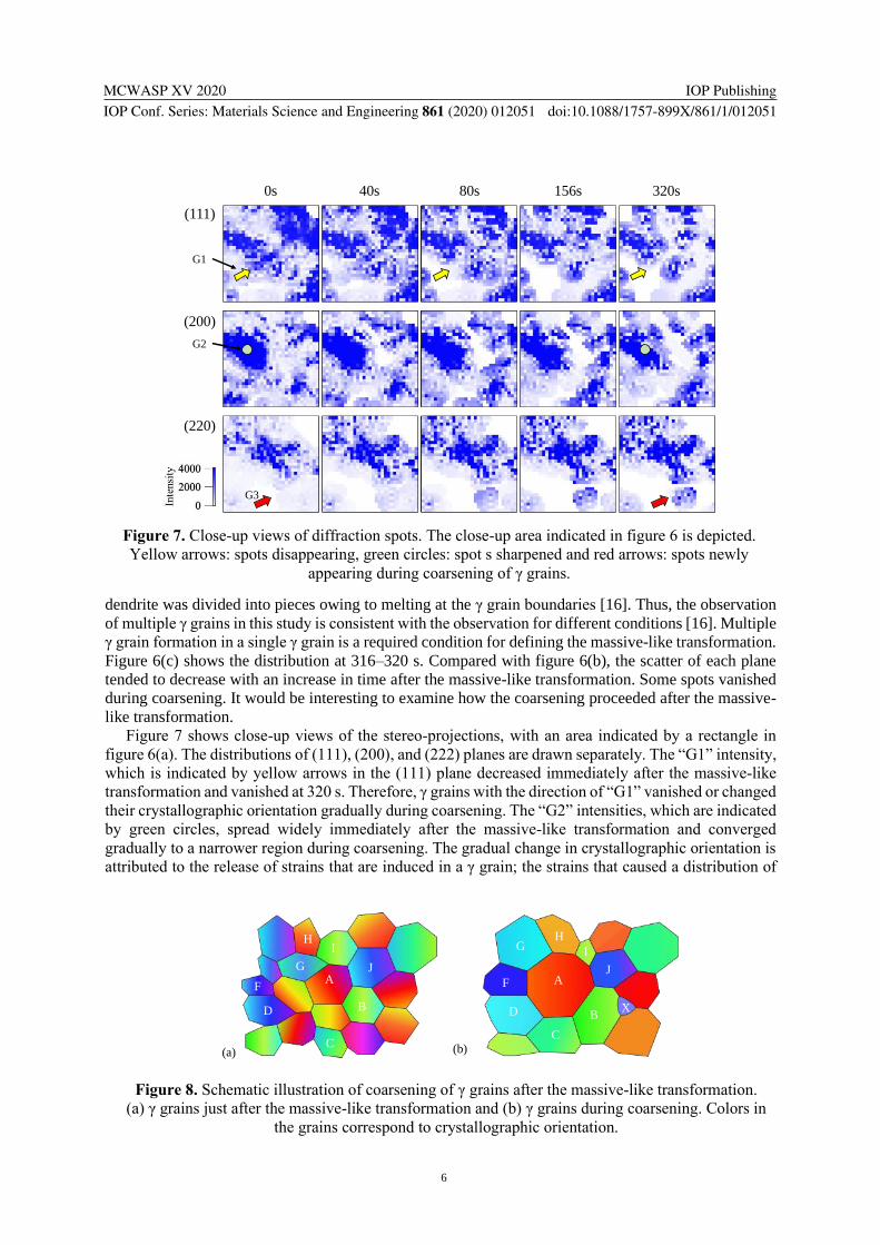
dendrite was divided into pieces owing to melting at the γ grain boundaries [16]. Thus, the observation
of multiple γ grains in this study is consistent with the observation for different conditions [16]. Multiple
γ grain formation in a single γ grain is a required condition for defining the massive-like transformation.
Figure 6(c) shows the distribution at 316–320 s. Compared with figure 6(b), the scatter of each plane
tended to decrease with an increase in time after the massive-like transformation. Some spots vanished
during coarsening. It would be interesting to examine how the coarsening proceeded after the massive-
like transformation.
Figure 7 shows close-up views of the stereo-projections, with an area indicated by a rectangle in
figure 6(a). The distributions of (111), (200), and (222) planes are drawn separately. The “G1” intensity,
which is indicated by yellow arrows in the (111) plane decreased immediately after the massive-like
transformation and vanished at 320 s. Therefore, γ grains with the direction of “G1” vanished or changed
their crystallographic orientation gradually during coarsening. The “G2” intensities, which are indicated
by green circles, spread widely immediately after the massive-like transformation and converged
gradually to a narrower region during coarsening. The gradual change in crystallographic orientation is
attributed to the release of strains that are induced in a γ grain; the strains that caused a distribution of
Figure 7. Close-up views of diffraction spots. The close-up area indicated in figure 6 is depicted.
Yellow arrows: spots disappearing, green circles: spot s sharpened and red arrows: spots newly
appearing during coarsening of γ grains.
(111)
(200)
(220)
0s 40s 80s 156s 320s
G1
G2
G3
Figure 8. Schematic illustration of coarsening of γ grains after the massive-like transformation.
(a) γ grains just after the massive-like transformation and (b) γ grains during coarsening. Colors in
the grains correspond to crystallographic orientation.
(a) (b)
A A
BB
CC
D
F
D
F
G
GHH
I I
JJ
X

MCWASP XV 2020
IOP Conf. Series: Materials Science and Engineering 861 (2020) 012051
IOP Publishing
doi:10.1088/1757-899X/861/1/012051
7
several degrees in the crystallographic orientation were introduced in the massive-like transformation.
The strains in this study are consistent with large strains that were observed by time-resolved Laue
diffraction using white X-rays [28]. Although it is difficult to estimate the distribution by XRD of white
X-rays, this study using a monochromatized X-ray to confirm the induced strains. The volume decreased
0.5 % by the transformation from δ to γ [18]. The volume change can induce strains within γ grains even
above 1673K. “G3” is indicated by red arrows formed, which suggests that new grains were produced
during coarsening. The production of new γ grains may correspond to strains within γ grain strain
produced by the massive-like transformation.
Figure 8 shows schematic illustrations of γ grains immediately after the massive-like transformation
and during coarsening to summarize the observation results. The fine γ grains in which strains are
induced are produced through the massive-like transformation. The crystallographic orientation changes
within a γ grains can reflect lattice defects in the γ grains. After the massive-like transformation, γ grains
coarsened and/or vanished. The strains that were induced in the γ grains were released and this process
can influence the kinetics of γ grain coarsening. The influence of the massive-like transformation
modifies the coarsening kinetics in subsequent cooling after solidification and is different, compared
with the kinetics [1–4].
4. Summary
The massive-like transformation in Fe–C alloys was examined by time-resolved X-ray imaging (2D
observation) and XRD on a 4D-CT setup.
The observation results for the unidirectional solidification were analysed extensively. In the
unidirectional solidification in 0.3C steel at 50 μm/s, δ dendrites, fine γ grains that were produced
through the massive-like transformation, and coarse γ grains can grow together in the steady state. The
XRD images indicated that fine γ grains formed during unidirectional solidification. Based on detailed
analysis, we concluded that the massive-like transformation was selected even at low growth rates.
Changes in the crystallographic orientations of γ grains during coarsening were analysed. Strains in
the γ grains were induced by the massive-like transformation. The fine γ grains coarsened and/or
vanished after the massive-like transformation and new γ grains formed. The strains were released
during coarsening. The massive-like transformation can modify the kinetics of γ grain coarsening.
Acknowledgments
In situ observations (2D and 3D observations) using synchrotron radiation X-rays were performed as
general projects (2016B1458, 2017B1463, 2018A1380, 2019A1400) at the BL20B2 and the BL20XU
of SPring-8 (JASRI), Japan. The study was initiated by “Heterogeneous Structure Control: Towards
Innovative Development of Metallic Structural Materials” in the Industry–Academia Collaborative
R&D Program (JST). The study was supported by a Grant-in-Aid for Scientific Research (S) (No.
17H06155). We thank Laura Kuhar, PhD, from Edanz Group (www.edanzediting.com/ac) for editing a
draft of this manuscript.
References
[1] Pottore N S, Garcia C I and DeArdo A J 1991 Metall. Trans. A 22 1871
[2] Cuddy L J and Raley J C 1983 Metall. Trans. A 14 1989
[3] Yoshida N, Kobayashi Y and Nagai K 2004 Tetsu-to-Hagane 90 198
[4] Manohar P A, Dunne D P, Chandra T and Killmore C R 1996 ISIJ Int. 36 194
[5] Tsuchiya S, Ohno M, Matsuura K and Isobe K 2011 Acta Mater. 59 3334
[6] Shibata H, Arai Y, Suzuki M and Emi T 2000 Metall. Mater. Trans. B 31 981
[7] Griesser S, Reid M, Bernhard C and Dippenaar R 2014 Acta Mater. 67 335
[8] Mathiesen R H, Arnberg L, Mo F, Weitkamp T and Snigirev A 1999 Phys. Rev. Lett. 83 5062
[9] Yasuda H, Ohnaka I, Kawasaki K, Sugiyama A, Ohmichi T, Iwane J and Umetani K 2004 J.
Cryst. Growth 262 645
[10] Li B, Brody H and Kazimirov A 2004 Phys. Rev. E 70 062602

MCWASP XV 2020
IOP Conf. Series: Materials Science and Engineering 861 (2020) 012051
IOP Publishing
doi:10.1088/1757-899X/861/1/012051
8
[11] Schenk T et al. 2005 J. Cryst. Growth 275 201
[12] Wang T, Xu J, Xiao T, Xie H, Li J, Li T and Cao Z 2010 Phys. Rev. E 81 42601
[13] Yasuda H et al. 2009 Int. J. Cast Met. Res. 22 15
[14] Yasuda H, Nagira T, Yoshiya M, Nakatsuka N, Sugiyama A, Uesugi K and Umetani K 2011 ISIJ
Int. 51 402
[15] Kareh K M, O’Sullivan C, Nagira T, Yasuda H and Gourlay C M 2017 Acta Mater. 125 187
[16] Yasuda H, Morishita K, Nakatsuka N, Nishimura T, Yoshiya M, Sugiyama A, Uesugi K and
Takeuchi A 2019 Nat. Commun. 10 3183
[17] Nishimura T, Morishita K, Yoshiya M, Nagira T and H Y 2020 ISIJ Int. in press
(doi:10.2355/ isijinternational.ISIJINT-2019-6)
[18] Nishimura T, Morishita K, Yoshiya M, Nagira T and Yasuda H 2019 Tetsu-To-Hagane 105 168
[19] Ludwig O, Dimichiel M, Salvo L, Suéry M and Falus P 2005 Metall. Mater. Trans. A 36 1515
[20] Aagesen L K, Fife J L, Lauridsen E M and Voorhees P W 2011 Scr. Mater. 64 394
[21] Daudin R, Terzi S, Lhuissier P, Salvo L and Boller E 2015 Mater. Des. 87 313
[22] Cai B, Karagadde S, Yuan L, Marrow T J, Connolley T and Lee P D 2014 Acta Mater. 76 371
[23] Karagadde S et al. 2015 Nat. Commun. 6 8300
[24] Gibbs J W, Mohan K A, Gulsoy E B, Shahani A J, Xiao X, Bouman C A, De Graef M and
Voorhees P W 2015 Sci. Rep. 5 11824
[25] Yasuda H, Hashimoto T, Sei N, Morishita K and Yoshiya M 2019 IOP Conf. Ser. Mater. Sci.
Eng. 529 012013
[26] Nakano K, Narumi T, Morishita K and Yasuda H 2020 Mater. Trans. 61 in press
[27] Yasuda H et al. 2011 IOP Conf. Ser. Mater. Sci. Eng. 27 012084
[28] Yasuda H et al. 2012 IOP Conf. Ser. Mater. Sci. Eng. 33 012036
[29] Nishimura T, Morishita K, Nagira T, Yoshiya M and Yasuda H 2015 IOP Conf. Ser. Mater. Sci.
Eng. 84 012062
[30] Nishimura T, Matsubayashi R, Morishita K, Yoshiya M, Nagira T and Yasuda H 2019 ISIJ Int.
59 459
[31] Goto S et al. 2001 Nucl. Instruments Methods Phys. Res. Sect. A Accel. Spectrometers, Detect.
Assoc. Equip. 467–468 682
[32] Liu T, Long M, Chen D, Huang Y, Yang J, Duan H, Gui L and Xu P 2020 Metall. Mater. Trans.
B 51 338
[33] Yoshiya M, Nakajima K, Watanabe M, Ueshima N, Nagira T and Yasuda H 2015 Mater. Trans.
56 1461