
Improvement of auxiliary BI-DRUM boiler operation by ... · developed a model to predict transient...
11
Improvement of auxiliary BI-DRUM boiler operation by dynamic simulation N. Romero-Anton * , K. Martin-Escudero, L.A. Portillo-Vald es, I. G omez-Elvira, E. Salazar-Herran Department of Thermal Engineering, Faculty of Engineering of Bilbao, University of the Basque Country UPV/EHU, Alda. Urquijo s/n, 48013, Bilbao, Spain article info Article history: Available online 7 February 2018 Keywords: Dynamic energy behaviour Hot startup Hot standby mode Natural circulation Bi-drum boiler abstract Due to Horizon 2030 objectives, industry is committed to improving traditional auxiliary bi-drum boilers performance in existing plants. In this study, a new operation methodology for auxiliary bi-drum boilers has been developed to reduce the operational cost of the plant. Two new functioning modes have been defined as “hot standby mode” (HSM) and “fast hot startup” (FHS). Both of them will be studied using thermal dynamic calculations. In addition, Power Plant Simulation & Design (PPSD) commercial software has been used for dynamic performance analysis. Results show that auxiliary bi-drum boilers will be able to operate under those conditions only if some additional technological modifications are implemented. For example, automated burners that are adapted to current standards, feed water control valve capable of regulating the flow during HSM, automate superheater valve drains and a continuous blow down valve. This new operation methodology will result in energy savings and reduction in operational cost. © 2018 Elsevier Ltd. All rights reserved. 1. Introduction Industry is interested in keeping auxiliary steam boilers operating at HSM and proceeded to a FHS (in around 10 min), as it enables a considerable energy and cost reduction as well as increase production efficiency. The present work defines two new operational modes, namely: Hot standby mode (HSM), an operation mode where the boiler is operating at nominal pressure condition but with a steam production and fuel consumption almost non-existent. The other operational mode, fast hot startup (FHS), has the aim to increase from minimum load to maximum designed load in the minimum of time. Industrial auxiliary steam boilers are essential equipment in conventional industrial plants, such as, thermal power plants, cogenerations, Combined Cycle Gas Turbines (CCGT), refineries, paper industries, as well as, renewable power plants. Considering their presence in different industries and the current economical situation it is crucial to carry out research and improve their design [1] to increase energy savings [2,3] with minimum capital investment. Industrial boilers have to face new challenges because they have to provide a fast reaction to the steam demand in the plant and also reduce environmental impact by minimizing emissions. As an example, Spain has regulated the emissions in standard R.D. 815/ 2013 [4]. Thanks to dynamic calculation, designers are able to study non-stationary situations. Therefore, boiler startup load changes and shut down operation cases can be studied and improved. During the past few years, boiler dynamics have been studied. The basis of these studies considered the conservation of mass, energy and momentum. The first studies were focused on natural circulation fluctuations during load change. Adam [5] developed two nonlinear analytical models to study evaporation dynamics in vertical tubes and phase separation in steam drum, which is so-called natural circulation. The model was applied to a bi-drum water-tube boiler of 30 MW with natural circulation. Åstr€ om [6] developed a nonlinear analytical model describing drum, evaporator and downcomer loops dynamics. The proposed model was based on empirical formulations derived from measurement data which reduced the number of unknown parameters in dynamic study. This article was the starting point for several researches such as, Franke [7], Kim [8] and Emara-Shabaik [9]. * Corresponding author. E-mail address: [email protected] (N. Romero-Anton). Contents lists available at ScienceDirect Energy journal homepage: www.elsevier.com/locate/energy https://doi.org/10.1016/j.energy.2018.01.160 0360-5442/© 2018 Elsevier Ltd. All rights reserved. Energy 148 (2018) 676e686
Transcript of Improvement of auxiliary BI-DRUM boiler operation by ... · developed a model to predict transient...
lable at ScienceDirect
Energy 148 (2018) 676e686
Contents lists avai
Energy
journal homepage: www.elsevier .com/locate/energy
Improvement of auxiliary BI-DRUM boiler operation by dynamicsimulation
N. Romero-Anton*, K. Martin-Escudero, L.A. Portillo-Vald�es, I. G�omez-Elvira,E. Salazar-HerranDepartment of Thermal Engineering, Faculty of Engineering of Bilbao, University of the Basque Country UPV/EHU, Alda. Urquijo s/n, 48013, Bilbao, Spain
a r t i c l e i n f o
Article history:Available online 7 February 2018
Keywords:Dynamic energy behaviourHot startupHot standby modeNatural circulationBi-drum boiler
* Corresponding author.E-mail address: [email protected] (N. Romer
https://doi.org/10.1016/j.energy.2018.01.1600360-5442/© 2018 Elsevier Ltd. All rights reserved.
a b s t r a c t
Due to Horizon 2030 objectives, industry is committed to improving traditional auxiliary bi-drum boilersperformance in existing plants.
In this study, a new operation methodology for auxiliary bi-drum boilers has been developed to reducethe operational cost of the plant.
Two new functioning modes have been defined as “hot standby mode” (HSM) and “fast hot startup”(FHS). Both of them will be studied using thermal dynamic calculations. In addition, Power PlantSimulation & Design (PPSD) commercial software has been used for dynamic performance analysis.
Results show that auxiliary bi-drum boilers will be able to operate under those conditions only if someadditional technological modifications are implemented. For example, automated burners that areadapted to current standards, feed water control valve capable of regulating the flow during HSM,automate superheater valve drains and a continuous blow down valve. This new operation methodologywill result in energy savings and reduction in operational cost.
© 2018 Elsevier Ltd. All rights reserved.
1. Introduction
Industry is interested in keeping auxiliary steam boilersoperating at HSM and proceeded to a FHS (in around 10min), as itenables a considerable energy and cost reduction as well asincrease production efficiency.
The present work defines two new operational modes, namely:Hot standby mode (HSM), an operation mode where the boiler isoperating at nominal pressure condition but with a steamproduction and fuel consumption almost non-existent. The otheroperational mode, fast hot startup (FHS), has the aim to increasefromminimum load tomaximum designed load in theminimum oftime.
Industrial auxiliary steam boilers are essential equipment inconventional industrial plants, such as, thermal power plants,cogenerations, Combined Cycle Gas Turbines (CCGT), refineries,paper industries, as well as, renewable power plants. Consideringtheir presence in different industries and the current economicalsituation it is crucial to carry out research and improve their design
o-Anton).
[1] to increase energy savings [2,3] with minimum capitalinvestment.
Industrial boilers have to face new challenges because they haveto provide a fast reaction to the steam demand in the plant and alsoreduce environmental impact by minimizing emissions. As anexample, Spain has regulated the emissions in standard R.D. 815/2013 [4]. Thanks to dynamic calculation, designers are able to studynon-stationary situations. Therefore, boiler startup load changesand shut down operation cases can be studied and improved.During the past few years, boiler dynamics have been studied. Thebasis of these studies considered the conservation of mass, energyand momentum. The first studies were focused on naturalcirculation fluctuations during load change. Adam [5] developedtwo nonlinear analytical models to study evaporation dynamics invertical tubes and phase separation in steam drum, which isso-called natural circulation. The model was applied to a bi-drumwater-tube boiler of 30MW with natural circulation. Åstr€om [6]developed a nonlinear analytical model describing drum,evaporator and downcomer loops dynamics. The proposed modelwas based on empirical formulations derived from measurementdata which reduced the number of unknown parameters indynamic study. This article was the starting point for severalresearches such as, Franke [7], Kim [8] and Emara-Shabaik [9].

Nomenclature
C empirical value that depends on fuel type (�)_QN Boiler heat output at 100% MCR (kW)_QEN Boiler heat losses (kW)_Q Heat transfer flow (kW)DT Temperature difference (ºC)R Total Thermal Resistance (K/W)U General heat transfer coefficient (W/m2K)A area (m2)Rconv&radiation Convection Thermal Resistance (K/W)Rwall Conduction thermal Resistance (K/W)h convection heat transfer coefficient (W/m2K)k conduction heat transfer coefficient (W/mK)x insulation thickness (m)As surface area (m2)n number of cycles (�)2fva variable stress (N/mm2)fv mean stress (N/mm2)t* reference temperature (ºC)N load cycles (�)Ct* Fatigue curve stress range temperature correction (�)2fa*t* Temperature corrected stress range (N/mm2)Ss Fatigue curve statistical scatter corrector factor (�)2fas Final notch, mean stress/plasticity, temperature and
statistical corrected stress range (N/mm2)
Nas minimum cycles to cracking at 2fas (�)SL statistical factor to adjust from mean to minimum
cycles to cracking (�)mass flow (t/h) steam production at boiler battery limitPressure (barg) steam pressure at boiler battery limitTH20,SH3 (ºC) superheater third tube bundle steam temperatureTmetal,SH3 (ºC) superheater third bundle tube metal temperatureTH20,SH2 (ºC) superheater second tube bundle steam
temperatureTmetal,SH2 (ºC) superheater second tube bundle metal
temperatureTH20,SH1 (ºC) superheater first tube bundle steam temperatureTmetal,SH1 (ºC) superheater first bundle tube metal temperature
AbbreviationsPPSD Power Plant Simulation & DesignCCGT Combined Cycle Gas TurbinesHRSG Heat Recovery Steam GeneratorMCR Maximum Continuous RatingWHB Waste Heat BoilerBL Battery LimitHSM hot standby modeFHS fast hot startupFG Flue gasSH SuperhetaerECO Economizer
N. Romero-Anton et al. / Energy 148 (2018) 676e686 677
Franke [7] implemented in Modelica Åstr€om [6] non-linear boilerdrum model. Kim [8] developed a model for water level predictionwhen steam demand is changing in a natural circulation drum-typeboiler. Obtained results were compared with Åstr€om's [6] results.Emara-Shabaik [9] developed a dynamic model based on Åstr€oms[6] to predict the temperature of the riser tubes in a water tubeboiler. In previous literature, the temperature of the riser tubes wassupposed to be equal to steam temperature.
Dynamic calculations have also been used for startup simula-tions. In CCGTs, for example, it is important for a fast startup tofollow the startup curve for gas turbines. The most critical factduring a startup is the fast increase of temperature, pressure andsteam flow. During this process, especially the steam drum and thesuperheater collector suffer thermal stresses as temperature is notproperly distributed along the thickness of the material. Kim [10]developed a model to predict transient characteristics of HRSG.Startup behaviour was also analysed paying special attention tothermal stress on the steam drum. In this model, water-steamconvection coefficient was calculated using Dittus-Boelter formu-lation and the temperature of the metal was considered to be equalto steam temperature. Krüger [11] studied drum-type boiler startupoptimization based on a non-linear model. Thermal stresscalculations were considered in the steam drum assuming thatthere was an unsteady flux. The optimization model was doneusing the commercial Dymola environment based on the openModelica language [12].
During dynamic calculations, special attention is required to twoother factors namely, thermal stress and the metal superheatertube temperature.
Regarding thermal stress, its determination in thick wallcomponents is very complicated as boundary conditions must becorrectly defined. Boiler designers always define some values toavoid thermal stress problems during startup. These values aredefined from a conservative point of view for boiler lifetime. For
example, the rate of fluid temperature variation in a steam drummust be constant and no more than 1 �C/min. This steam temper-ature variation will imply a uniform temperature distribution inthickwalled components during startup. But when the startup timeneeds to be reduced and the constant temperature rate of 1 �C/minis not fulfilled thermal stress should be studied. The most commonmethod to study thermal stress in thick walled components isEN-12952-3 European standard [13]. Taler developed a methodol-ogy to reduce startup time avoiding thermal stress in thick walledcomponents [14]. He proposed to fill up the steam drum with hotwater before startup. The results showed that startup time could bereduced from 6.5 h to 2 h using his method. These calculations weremade based on the mathematical dynamic model developed inRef. [15]. To overcome thermal stress in thick wall components,new techniques for measuring the transient temperature of fluidflowing in the pipeline have also been studied [16].
Regarding the temperature of the metal tube, when the tem-perature is higher than expected, tubes could break. Therefore, it isvery important to select the correct material at design stage. Duringload changes or boiler startup the temperature in the tubes increaserapidly as there is no cold water or steam inside the tubes to cool itdown. Considering these situations several studies were carried out[27,28] [29]. In all of them tube failure locations occurred in thesuperheater tubes.
Apart from the analytical nonlinear models developed for boilerdynamic study, commercial software is also used. In the literature,four commercial softwarewere found;Modelica, Simulink&Matlab,ASPEN and APROS. Modelica was used by Franke [7] implementingAstrom [6] non-linear model. The goal was to improve boilerstartup in order to minimize cost and environmental impact duringplant operation on a 700 kW coal fired drum boiler. Casella [17]simulated a combined cycle power plant startup and reduced itstime from 25,300s to 19,200s by removing intermediate stopsduring startup. In this new situation thermal stress in thick walled
N. Romero-Anton et al. / Energy 148 (2018) 676e686678
components was studied in detail. Sedi�c [18] used Matlab andSimulink to simulate a dynamic behaviour of a fuel oil single drumboiler and in contrast with [6] empirical relationships wereavoided. The model was made to be applicable to any type of boilerfacility. Alobaid developed several models based on AdvancedProcess Simulation Software (APROS) studying cold, warm and hotstart ups in different types of boilers, for instance a vertical HRSGboiler [19], a triple pressure supercritical one-through HRSG [20]and Benson one through sub-critical boiler [21] were simulated.ASPEN was also used to simulate three pressures HRSG boilersduring startup procedure [22]. A comparison between ASPEN andAPROS tools was made considering a three pressure forcedcirculation HRSG [23,24]. In conclusion, similar results wereobtained with both models. Nicolas used APROS [25] to comparewarm and hot startup time in HRSG and one through HRSG boilerand to study dynamics on a three vertical HRSG pressure boilers[26].
Research was made regarding fast startup and dynamic calcu-lations using commercial software or developed numerical models.In all of them, special attention was paid to the temperature of thesuperheater tubes and the steam drum thermal stress. However,neither studied the fast startup of 10min fromHSM, which is belowthe technical minimum load. The proposed methodology in thisarticle differs from other authors' methodology on HSM. It is anoperating mode where boilers are operating below their minimumtechnical load at nominal pressure conditions. Therefore, theboilers are kept in hot conditions with a steam production almostnon-existent. As the boilers are already prepared they are able to doa fast startup, in the case study the plant needs the boilers at 100%Maximum Continuous Rate (MCR) within 10min.
Other methodologies study boiler startups by considering themas shut down, a so-called “cold startup”. The advantage of thismethodology is that boilers are not consuming any fuel as they areshut down. The disadvantage of shutting down the boilers is that itis not possible to do a fast startup in 10min. The cold startup timetakes around 6 h for these specific boilers as thermal stress must bechecked. As an example, Taler [14] developed an operating meth-odology to reduce cold startup time from 6.5 h to 2 h, but with thismethodology startup in 10min is still not possible.
Others authors studied startup when boilers are operating attheir minimum load [21]. In this case, the advantage is that asboilers are already hot, it is possible to do a startup in shorter time.Moreover, this methodology does a fast startup from minimumtechnical load to maximum load 100%MCR. According to boilerdesigners companies, boilers' minimum load is 10% MCR. Thedisadvantage of this methodology is that if there is no steam de-mand on the plant, there is a waste of energy, as boilers are not ableto supply a steam production below their minimum technical load.
The proposed methodology in this article takes advantage andcombines the benefits of the other methodologies proposed bypreviously named authors: (1) At HSM the boilers have an almostnon-existent steam production. (2) At HSM boilers are already hotso a FHS in 10min is possible. The disadvantage of this methodol-ogy is the required initial capital investment. Burner design isspecial, not standardised, and FHS control philosophy description ismuch more complex.
In conclusion, HSM implies an increase in boiler flexibility andenergy and cost savings and so is considered a very attractiveoperational strategy.
2. Problem set up
For this study a petrochemical plant located in the north of Spainis selected. This petrochemical plant reuses wasted heat to produce
steam for the plant functioning. Mainly gas turbines and waste heatboilers (WHB) are used in this plant. At the same time, three over-sized auxiliary bi-drum boilers are also operating at their minimumload so that WHB and other oversized auxiliary boilers operating attheir minimum load can cover the base steam of the plant.
Auxiliary bi-drum boilers are designed oversized to produce thenecessary steam demanded from the plant when WHB stopworking for any circumstance, such as maintenance or breakdownand also during peak and fluctuations of the steam demand.Oversized auxiliary bi-drum boilers are normally operating at theirminimum load 10%MCR andwhen it is required, they start workingat full load 100%MCR.
Recently, the plant made some changes in their process so thatwaste heat was better reused. Due to these improvements, overallplant efficiency increased and the steam demanded from the plantwas reduced. Therefore,WHB cover the base steam demanded fromthe plant and it is not necessary to produce steam using theauxiliary boilers. The traditional technology of auxiliary boilers donot allow them to work below their minimum load (10%MCR) sothere is a steam production which is wasted in the plant. A newoperational methodology is necessary on auxiliary bi-drum boilersto reduce the cost of the plant and energy waste.
The solution to this problem could be to shut down auxiliaryboilers. In any case this is not a possibility because when there is apeak or a variation in steam demand or when WHB stop working,auxiliary boilers cover those steam demand fluctuations. Shuttingdown the boilers means losing the possibility of doing a fast startupwithin 10min. Boilers would be cold and it would take six hours toprepare them for full operational load. This is not acceptable as theplant requires a FHS in 10min and for this reason the plant requiresthat boilers are kept operating in hot conditions and constantpressure conditions.
HSM and FHS operation modes are the new operation modesnecessary for the three auxiliary steam boilers. It is not feasible toshut down one boiler and maintain the other two in HSM. WhenWHB stop working, it is necessary to produce steam in the threeauxiliary boilers at 100%MCR to provide steam for plant operations.Therefore, the three auxiliary steam boilers must be ready for FHS.Due to plant characteristics, fast startup must be feasible within10min, so HSM and FHS are needed requiring the development ofthe necessary technology to modify and include those operationsmodes in traditional steam generators.
3. Description of the auxiliary bi-drum boiler
The described boilers started operation in February 1983. Thewater tube bi-drum boiler is a two drum, bottom supported, nat-ural circulation boiler with multiple gas pass designed to burn fuelgas. The furnace is fully water cooled using the membrane wallconstruction. A unique plenum encloses the upper front wall, roofand rear of the unit. The design enables the flue gases to flowhorizontally and parallel to the drums through the evaporatingbank.
An inverted loop drainable superheater is located behind ascreen at the furnace outlet to protect it from direct furnace radi-ation. This location gives a semi-radiant heat transfer characteristic,which guarantees superheater temperatures at low loads (seeFig. 1). An economizer is used to reduce exhaust gas temperatureand improve boiler efficiency.
Cyclone steam separators with secondary scrubbers areincluded in the steam drum to produce high quality steam.
The steam generators are designed for a steam production of42.5 bar(g) at 371 �C and 90,000 kg/h firing fuel gas. The boiler andauxiliary equipment are designed to operate from 10%MCR to 100%MCR.

Burners
Steam drum
Water drum
Risers
Fig. 1. Steam generator.
N. Romero-Anton et al. / Energy 148 (2018) 676e686 679
Additionally, the described boiler is a natural circulation boiler,where water-steam mixture flows naturally inside the tubes. Themain components forming a natural circulation loop are a steamdrum, downcomer tubes and riser tubes. Feedwater enters theboiler steam drum from the economizer. Water flows to the waterdrum through a number of downcomer tubes after which thewater-steammixture flows back to the steamdrum through amuchlarger number of riser tubes. Furnace heat is transferred to riserwall tubes where steam is starting to form. As steam-water mixtureis less dense than water in downcomer tubes, gravity will causewater to move downwards while water-steam mixture movesupwards. The rate of water flow depends on the average densitydifference between the unheated water and the heated steam-water mixture. In natural circulation, the density differencebetween water and the steam-water mixture produces enoughforce to overcome frictional and gravitational resistance to flow andproduce a velocity of circulation sufficient to always maintain aflow of steam through the tubes, which avoids overheating of thetubes.
Boilers have four fuel gas burners arranged in two levels, with adistribution of two burners per level. Each burner is designed for apower release of 33%MCR with a turn down ratio of 1:7. They aredesigned for manual operationwhere the furnace is purged and theburner started, ignited and stopped manually, each burner's airregister is also manually operated.
A schematic flow diagram of one auxiliary bi-drum boiler isshown in Fig. 2.
The main characteristics of the boiler are summarized in Table 1.Current auxiliary boilers are working at their minimum load,
10%MCR. Produced steam is wasted in the plant, this corresponds toa steam mass flow of 9000 kg/h equivalent to a thermal power of6.9MW and a loss of 178V/h per boiler. Auxiliary boilers areoperating at standby mode 30% of the year, that is, 2628 h/year. Therest are supplying steam to overcome plant steam fluctuationsdemand.
4. Results
The main result of this article is the methodology proposed asdiffers from other authors' methodology on HSM. The confirmationthat this operation methodology is applicable is the main
conclusion. Thanks to HSM, boilers are already prepared to do a FHSin 10min while operating below 10% MCR.
Other methodologies study boiler cold startups, in these casesthe boilers are not hot so it is not possible to do a fast startup within10min. For the boilers described in this paper 6 h are required toheat the boilers to operating at 100%MCR when initially the boilerswere shut down. Despite the fact that some research has shown thepossibility to reduce this time substantially [14], a startup within10min was still considered impossible.
Previous authors studied startups when boilers were operatingat their minimum load [21]. In this case it is possible to do a startupin shorter time, but these methodologies do a fast startup from 10%MCR to 100% MCR. However, if there is no steam demand on theplant there is a waste of energy as boilers are not able to supply asteam production below their minimum technical load.
With the proposedmethodology boilers operating at HSM couldrealize a FHS in 10min starting with almost zero steam production.Although the presented methodology will result in cost and energysavings, the main drawback is that the initial investment is high.Special equipment will need to be purchased in order to be able towork under these conditions.
In order to validate proposed new operation methodology, HSMand FHS must be studied.
4.1. Hot standby mode (HSM)
HSM is defined as the minimum steam load at which a boiler isoperating with constant nominal pressure condition. The heat lossthrough the boiler enclosure will suppose a pressure reduction. Inorder to maintain a constant steam pressure it is necessary tointroduce a power input equal to the heat loss through the enclo-sures. That power input is introduced by boiler burners; therefore,HSM is defined with burner power input equal to heat loss. Toachieve that, heat transfer loss through boiler enclosures must becalculated. There are two different methods:
Method 1: Heat transfer loss is calculated applying radiation,convection and conduction heat loss formulation.
Considering boiler wall tubes like a plane wall and applyingthermal electrical analogy, heat transfer and thermal resistancesare defined as:

Fig. 2. Flow diagram of auxiliary bi-drum boiler.
Table 2Heat loss calculation.
Heat loss calculated with insulation
Boiler surface 273.1 m2
Others items surface 20 m2
Economizer surface 108 m2
Boiler tube wall temperature 255 ºCAmbient temperature 25 ºCInsulation material mineral woolInsulation thickness 75 mmInsulation conductivity 0.051 W/mKRadiation and convection coefficient 9.6 W/m2KHeat Flux 146.05 W/m2
Surface temperature 40.21 ºCInsulated surface 401.1 m2
Heat loss through insulated surface 58.58 kWUninsulated surface 2 m2
Heat lose uninsulated surface 4.42 kWTotal heat loss 63 kW
N. Romero-Anton et al. / Energy 148 (2018) 676e686680
_Q ¼ DTR
¼ UADT (1)
Rconv&radiation ¼ 1hAS
(2)
Rwall ¼xkA
(3)
For the calculation it is assumed that:
� Tube wall temperature is equal to steam temperature (255 �C)� Ambient temperature is equal to 25 �C� Ambient combined radiation and convection heat transfercoefficient is 9.6W/m2K.
� Insulation material is mineral wood with a thermal conductivityof 0.051W/mK
Applying the above formulation and assumption, calculatedheat loss is showed in Table 2.
Method 2: To apply European standard EN 12952-15 [30].According to EN12952-15 European standard heat losses are
described by:
Table 1Boiler characteristics.
Variable Value Units
Boiler type Bi-drum water tube boilerCirculation Natural circulationFurnace dimensions Height 4100
Width 4420Length 5750
mm
Refractory in furnace floor YESNumber of burners 4Burners arrangement Two levelsSteam Flow (100% MCR) 90,000 Kg/hSteam Pressure 42.5 barSteam Temperature 371 ºCThermal power input 69 MW
_QEN ¼ C* _Q0:7N (4)
The obtained results can be seen in Table 3.Comparing the heat loss calculated with both methods, the
result obtained from EN-12952-15 standard is the least favourable.The least favourable value is selected, so that the boiler will have aheat transfer loss through boiler enclosures of 215 kW. To overcomeheat transfer losses and guarantee HSM the minimum powernecessary to introduce to boiler furnace is 215 kW.
As mentioned before, each existing manual burner is designedfor a power release of 33%MCR with a turn down ratio of 1:7.Considering that the power input necessary at full load is 69MW,each burner minimum load is 3.3MW. Therefore, existing burnersare not capable of supplying 215 kW. Considering those values, anew design for the combustion system is necessary for HSM.
Table 3EN 12952-15 heat loss calculation.
Heat loos according to EN 12952-15
Heat output water/steam 67,408 kWType of fuel Light Oil or natural gasC 0.0113_QEN
215.4 kW

Table 4HSM process data.
Variable Value Units
Steam flow < 100 Kg/hSteam temperature 254 ºCSteam pressure 42.5 barCombustion air flow 500 Nm3/hFeed water temperature 142 ºCFuel gas flow 16 Nm3/hBurner power 215 kWBoiler pressure drop 0 mm.w.c.
Fig. 4. Water/steam scheme.
N. Romero-Anton et al. / Energy 148 (2018) 676e686 681
The results obtained from thermal calculations at the definedminimum load called HSM are shown in Table 4.
According to Table 4, defined boiler HSM is suitable to a steamproduction of 100 kg/h and a fuel consumption of 16 Nm3/h.Comparing with the existing available minimum load,10%MCR, thisnew operation mode will suppose energy savings and costreduction.
4.2. Fast hot startup study (FHS)
When there is a problem in the plant and WHB break downauxiliary boilers should be able to supply a steam production of90,000 kg/h at nominal conditions in no more than 10min fromHSM. To guarantee FHS it is necessary to do thermal dynamiccalculations. However, the burner ramp up shall first be defined asit is the set point for the dynamic calculations. To validate definedburner ramp and dynamic calculations the following items must bechecked:
1. Drum swell, to guaranty an accurate steam drum level control.2. Superheater tube metal temperature, to avoid tube overheating
and rupture.3 Thermal stress in steam drum.
Power Plant Simulator & Designer (PPSD) commercial softwarewas used to study thermal dynamic calculation. PPSD is a softwareof the company KED GmbH for the modeling of thermodynamicprocesses and steam generators. PPSD is mainly used in calcula-tions and design of steam generators and power plants. The soft-ware was developed in 1993 by Grigory Doverman and Christian
Fig. 3. Fuel gas scheme.
Daublebsky of Eichhain as a training simulator for PC-DOS-basedpower plants with a graphical interface. Later, the program wasadapted for the design of steam generators and heat exchangers,subsequently extended to entire power stations [31].
PPSD includes flue gas, water/steam, natural circulation and fuelschemes. Flue gas path is modeled on flue gas scheme from at-mospheric air supply to economizer exit, see Fig. 3. It consists ofatmospheric air supply, a furnace, a superheater heat exchanger, aradiation cavity, an evaporator and an economizer. Division wallsand water-tube walls are also represented. An air controller con-nects the air supply to the furnace. In the diagram flue gas velocityon each element and flue gas temperature between each elementcan be checked.
The water/steam path, see Fig. 4, is modeled on another schemefrom feed water supply to steam battery limit. Battery limit (LS) ismodeled as inlet boundary condition together with temperature,mass flow and the defined pressure parameters. The water level ofthe steam drum is controlled by supply water and the steam pro-duced in the evaporator. Water is heated by flue gas in the evapo-rator and converted into saturated steam in the steam drum afterpassing through steam separators. The saturated water is trans-ported to the evaporator, thanks to the natural circulation, and thenreheated. The dry steam exits the steam drum and flows throughthe superheater, which is divided into three tube bundles. Betweenthe first and second superheater tube bundle an attemperator islocated. The attemperator has another control which regulateswater supply to guarantee 371 �C at battery limit. At battery limit,the last control can be found, which regulates the fuel gas supply toguarantee 90,000 kg/h.
Heat exchange bundles commonly called superheaters, evapo-rators and economizers have been implemented using real dimen-sional data. Dimensional data is preferably defined on the flue gasscheme as evaporators do not appear in the water/steam scheme.After the element connections, circuit control elements are defined.It is basic procedure to use and define controllers for dynamicbehaviour calculation, such as, the drum level, the attemperator andthe fuel controller. In the natural circulation scheme all the equip-ment engaged in the water/steam path is displayed. Finally, in thefuel scheme the different fuel compositions are defined.
4.2.1. Steady state model validationAuxiliary bi-drum boiler model verification and evaluation with
the design data for steady state 100% full load is performed.
100
150
200
250
300
350
400
450
30 50 70 90 110
Tem
pera
ture
(ºC)
Boiler load (%)
Boiler FG (design data) Boiler FG (simulation)Economizer FG (design data) Economizer FG (simulation)SH (design data) SH (simulation)
Fig. 5. Auxiliary bi-drum boiler temperatures outlet at different loads.
N. Romero-Anton et al. / Energy 148 (2018) 676e686682
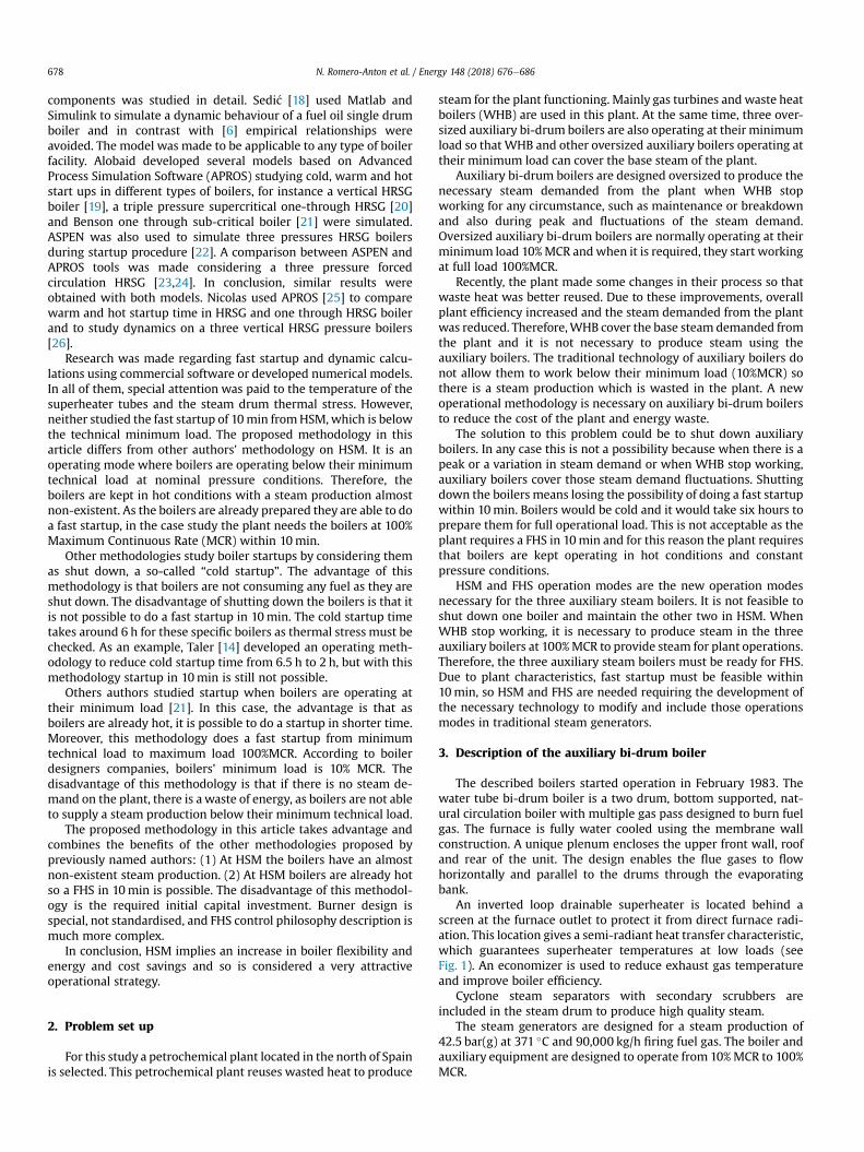
Another examination is made testing auxiliary bi-drum boiler at110%, 70%, and 30% part loads. Therefore steam mass flow, excessair, pressure outlet and feed water inlet temperature boundaryconditions are changed for part load simulation. Fig. 5 presents thesuperheater steam temperature, economizer flue gas outlet tem-perature and boiler flue gas outlet temperature; Fig. 6 shows thefuel mass flow at different loads.
The comparison between the simulations and the design datacorrelate well with each other. Thanks to the attemperator,
100
1100
2100
3100
4100
5100
6100
30 50
Mas
sflo
w(k
g/h)
Bo
Fuel masFuel mas
Fig. 6. Auxiliary bi-drum boiler fuel m
superheater steam outlet temperature is kept constant equal to371 �C. It is independent of the load change in both the simulationand the design data. Economizer flue gas outlet temperature resultsmatch well with design data. At 110% and 100% load the modelincorrectly predicts the flue gas temperature at the boiler outlet.However, the model does follow the same tendency as the designdata. Although the simulated flue gas boiler outlet temperature is11% higher than the given one, the economizer flue gas outlettemperature has less than 1.5% error between design and
70 90 110iler load (%)
s flow (design data)s flow (simulation)
ass flow outlet at different loads.
0
10
20
30
40
50
60
70
0 1 2 3 4 5 6 7 8 9 10
Bur
ner l
oad
(MW
)
Time (min)Fig. 7. Burner ramp.
N. Romero-Anton et al. / Energy 148 (2018) 676e686 683
simulation results. Furthermore, the computed fuel mass flowconsumption corresponds accurately to the design flow consump-tion, where the relative error between the simulation and thedesign is less than 1.2%.
Once the auxiliary bi-drum boiler model has been compared tothe design data for steady state and different load changes havebeen performed with high accuracy, the fast startup simulationswith validated model can be produced.
Table 6Steam generator volume and weight data.
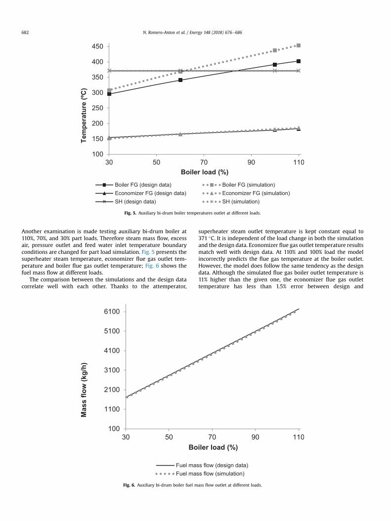
4.2.2. Burner rampBurner ramp is the burners' power release. The higher the po-
wer liberation the lower the time needed to achieve nominalconditions. Burner power liberation is defined as a function of timeto allow auxiliary boilers operating at full load in 10min.
The basic considerations for FHS and burner ramp definitionsare:
� The steam generator is in HSM at 42.5 bar(g).� The steam generator is kept in HSM with a burner load of215 kW
� Superheater drain valves must be opened during the first mi-nutes of the startup.
� With 2000 kW burner power, there must be a minimum flowthrough the terminal steam valve of at least 1 t/h (in this situ-ation it is recommended to close superheater drain valves).
� After 10min from startup signal the steam generator must bedelivering a steam production of 90,000 kg/h, 42.5 bar(g) and371 �C.
� The live steam terminal valve is controlling the pressure duringthe startup
� Burner's ramp power release during FHS follows Fig. 7.� Air excess during FHS shall be according to Table 5.
Defined excess air during FHS shall follow the data of Table 5.As illustrated in Table 5, the excess air is higher at lower per-
formance load. This is to get a complete combustion and to main-tain the flame direction in the furnace, thus avoiding flame flash-back.
Table 5Excess air definition.
%MCR 25 50 75 100
Excess Air 1.35 1.22 1.15 1.12
The burner's defined minimum load is 215 kW. Existing burnersare not able to supply such a minimum power, so existing com-bustion systems shall be replaced. Besides, they are manualburners; so one operator per burner is needed during startup tomanually modify the air register position which takes more than10min to startup.
The proposed design is to replace the four manual burners byfour newautomatic burners of 17.5MW in order to guarantee a FHS.
To guarantee a power release of 215 kW and in order to have ahomogeneous power release to the furnace, the two burners on thefirst level should have special igniters capable of releasing a powerfrom 100 kW to 700 kW.With such power output, the boiler shouldoperate in HSM by the special igniters located on the burners on thefirst level.
Following the defined burner ramp, FHS could be made within10min. In order to validate defined burner ramp and FHS, threeitems must be checked: drum swell, superheated tube metal tem-perature and thermal stress in steam drum.
In addition the volume of water and weight to be heated duringFHS is considered in thermal dynamic calculation, the values ofwhich are shown in Table 6.
4.2.3. Drum swellDue to the rapid increase in burner ramp, a fictitious increase in
boiler water level is produced by the increase of bubbles in thewater-steam circuit due to heating. This water level increase mustbe studied to confirm that there will not be steam drumwater levelproblems with the defined burner ramp for FHS.
For the drum swell calculation the water mass storage in thepressure boiler before and after the startup should be compared.The water mass difference corresponds to the water stored in thesteam drum. This water mass accumulation will increase the waterlevel. It is important to check that this situation does not happen. InTable 7 the data obtained for drum swell calculation can be seen.
Volume (m3) Weight (kg)
Steam generator 20 50,000Steam drum 11.6 24,000Mud/Water drum 1.4 6000Economizer 10 32,000Superheater & headers 3.7 12,500
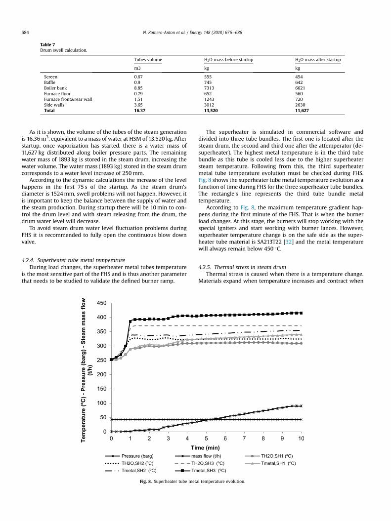
Table 7Drum swell calculation.
Tubes volume H2O mass before startup H2O mass after startup
m3 kg kg
Screen 0.67 555 454Baffle 0.9 745 642Boiler bank 8.85 7313 6621Furnace floor 0.79 652 560Furnace front&rear wall 1.51 1243 720Side walls 3.65 3012 2630Total 16.37 13,520 11,627
N. Romero-Anton et al. / Energy 148 (2018) 676e686684
As it is shown, the volume of the tubes of the steam generationis 16.36m3, equivalent to a mass of water at HSM of 13,520 kg. Afterstartup, once vaporization has started, there is a water mass of11,627 kg distributed along boiler pressure parts. The remainingwater mass of 1893 kg is stored in the steam drum, increasing thewater volume. The water mass (1893 kg) stored in the steam drumcorresponds to a water level increase of 250mm.
According to the dynamic calculations the increase of the levelhappens in the first 75 s of the startup. As the steam drum'sdiameter is 1524mm, swell problems will not happen. However, itis important to keep the balance between the supply of water andthe steam production. During startup there will be 10min to con-trol the drum level and with steam releasing from the drum, thedrum water level will decrease.
To avoid steam drum water level fluctuation problems duringFHS it is recommended to fully open the continuous blow downvalve.
4.2.4. Superheater tube metal temperatureDuring load changes, the superheater metal tubes temperature
is the most sensitive part of the FHS and is thus another parameterthat needs to be studied to validate the defined burner ramp.
0
50
100
150
200
250
300
350
400
450
0 1 2 3 4Tem
pera
ture
(ºC)-
Pres
sure
(bar
g)-S
team
mas
sflo
w(t/
h)
TimPressure (barg) maTH2O,SH2 (ºC) THTmetal,SH2 (ºC) Tm
Fig. 8. Superheater tube meta
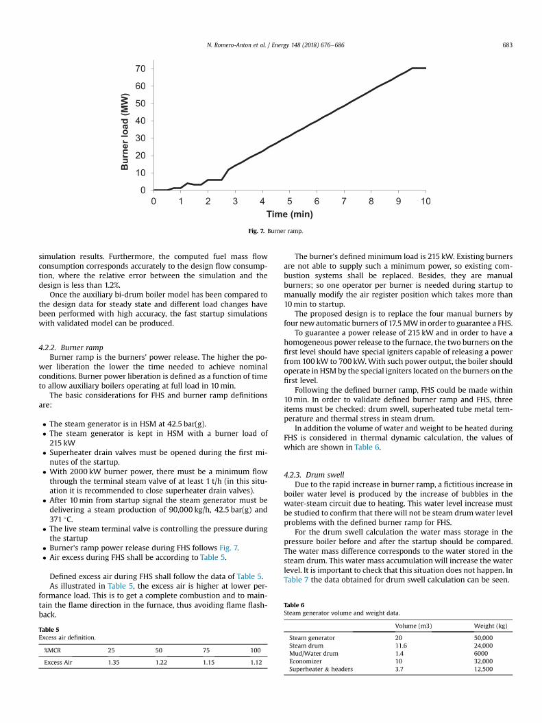
The superheater is simulated in commercial software anddivided into three tube bundles. The first one is located after thesteam drum, the second and third one after the attemperator (de-superheater). The highest metal temperature is in the third tubebundle as this tube is cooled less due to the higher superheatersteam temperature. Following from this, the third superheatermetal tube temperature evolution must be checked during FHS.Fig. 8 shows the superheater tube metal temperature evolution as afunction of time during FHS for the three superheater tube bundles.The rectangle's line represents the third tube bundle metaltemperature.
According to Fig. 8, the maximum temperature gradient hap-pens during the first minute of the FHS. That is when the burnerload changes. At this stage, the burners will stop working with thespecial igniters and start working with burner lances. However,superheater temperature change is on the safe side as the super-heater tube material is SA213T22 [32] and the metal temperaturewill always remain below 450 �C.
4.2.5. Thermal stress in steam drumThermal stress is caused when there is a temperature change.
Materials expand when temperature increases and contract when
5 6 7 8 9 10e (min)
ss flow (t/h) TH2O,SH1 (ºC)2O,SH3 (ºC) Tmetal,SH1 (ºC)etal,SH3 (ºC)
l temperature evolution.
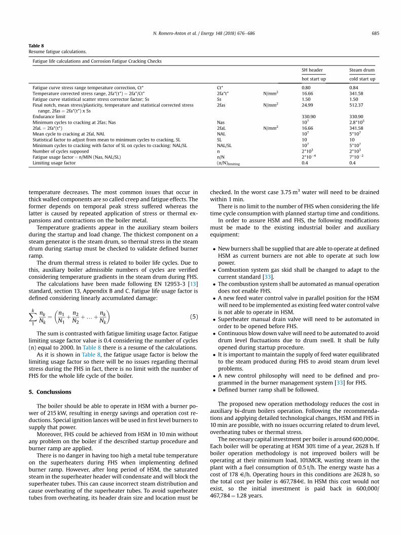
Table 8Resume fatigue calculations.
Fatigue life calculations and Corrosion Fatigue Cracking Checks
SH header Steam drum
hot start up cold start up
Fatigue curve stress range temperature correction, Ct* Ct* 0.80 0.84Temperature corrected stress range, 2fa*(t*) ¼ 2fa*/Ct* 2fa*t* N/mm2 16.66 341.58Fatigue curve statistical scatter stress corrector factor; Ss Ss 1.50 1.50Final notch, mean stress/plasticity, temperature and statistical corrected stress
range, 2fas ¼ 2fa*(t*) x Ss2fas N/mm2 24.99 512.37
Endurance limit 330.90 330.90Minimum cycles to cracking at 2fas; Nas Nas 107 2.8*105
2faL ¼ 2fa*(t*) 2faL N/mm2 16.66 341.58Mean cycle to cracking at 2fal, NAL NAL 107 5*107
Statistical factor to adjust from mean to minimum cycles to cracking, SL SL 10 10Minimum cycles to cracking with factor of SL on cycles to cracking: NAL/SL NAL/SL 107 5*107
Number of cycles supposed n 2*103 2*103
Fatigue usage factor¼ n/MIN (Nas, NAL/SL) n/N 2*10�4 7*10�2
Limiting usage factor (n/N)limiting 0.4 0.4
N. Romero-Anton et al. / Energy 148 (2018) 676e686 685
temperature decreases. The most common issues that occur inthickwalled components are so called creep and fatigue effects. Theformer depends on temporal peak stress suffered whereas thelatter is caused by repeated application of stress or thermal ex-pansions and contractions on the boiler metal.
Temperature gradients appear in the auxiliary steam boilersduring the startup and load change. The thickest component on asteam generator is the steam drum, so thermal stress in the steamdrum during startup must be checked to validate defined burnerramp.
The drum thermal stress is related to boiler life cycles. Due tothis, auxiliary boiler admissible numbers of cycles are verifiedconsidering temperature gradients in the steam drum during FHS.
The calculations have been made following EN 12953-3 [13]standard, section 13, Appendix B and C. Fatigue life usage factor isdefined considering linearly accumulated damage:
Xk1
nkNk
¼�n1N1
þ n2N2
þ…þ nkNk
�(5)
The sum is contrasted with fatigue limiting usage factor. Fatiguelimiting usage factor value is 0.4 considering the number of cycles(n) equal to 2000. In Table 8 there is a resume of the calculations.
As it is shown in Table 8, the fatigue usage factor is below thelimiting usage factor so there will be no issues regarding thermalstress during the FHS in fact, there is no limit with the number ofFHS for the whole life cycle of the boiler.
5. Conclussions
The boiler should be able to operate in HSM with a burner po-wer of 215 kW, resulting in energy savings and operation cost re-ductions. Special ignition lances will be used in first level burners tosupply that power.
Moreover, FHS could be achieved from HSM in 10min withoutany problem on the boiler if the described startup procedure andburner ramp are applied.
There is no danger in having too high a metal tube temperatureon the superheaters during FHS when implementing definedburner ramp. However, after long period of HSM, the saturatedsteam in the superheater header will condensate and will block thesuperheater tubes. This can cause incorrect steam distribution andcause overheating of the superheater tubes. To avoid superheatertubes from overheating, its header drain size and location must be
checked. In the worst case 3.75m3 water will need to be drainedwithin 1min.
There is no limit to the number of FHS when considering the lifetime cycle consumption with planned startup time and conditions.
In order to assure HSM and FHS, the following modificationsmust be made to the existing industrial boiler and auxiliaryequipment:
� New burners shall be supplied that are able to operate at definedHSM as current burners are not able to operate at such lowpower.
� Combustion system gas skid shall be changed to adapt to thecurrent standard [33].
� The combustion system shall be automated as manual operationdoes not enable FHS.
� A new feed water control valve in parallel position for the HSMwill need to be implemented as existing feedwater control valveis not able to operate in HSM.
� Superheater manual drain valve will need to be automated inorder to be opened before FHS.
� Continuous blow down valve will need to be automated to avoiddrum level fluctuations due to drum swell. It shall be fullyopened during startup procedure.
� It is important to maintain the supply of feed water equilibratedto the steam produced during FHS to avoid steam drum levelproblems.
� A new control philosophy will need to be defined and pro-grammed in the burner management system [33] for FHS.
� Defined burner ramp shall be followed.
The proposed new operation methodology reduces the cost inauxiliary bi-drum boilers operation. Following the recommenda-tions and applying detailed technological changes, HSM and FHS in10min are possible, with no issues occurring related to drum level,overheating tubes or thermal stress.
The necessary capital investment per boiler is around 600,000V.Each boiler will be operating at HSM 30% time of a year, 2628 h. Ifboiler operation methodology is not improved boilers will beoperating at their minimum load, 10%MCR, wasting steam in theplant with a fuel consumption of 0.5 t/h. The energy waste has acost of 178 V/h. Operating hours in this conditions are 2628 h, sothe total cost per boiler is 467,784V. In HSM this cost would notexist, so the initial investment is paid back in 600,000/467,784¼1.28 years.
N. Romero-Anton et al. / Energy 148 (2018) 676e686686
References
[1] Pronobis M. 12th international conference on boiler technology 2014 “currentissues of construction and operation of boilers”. Energy 2014;(92):1e2.
[2] Communication from the commission to the european parliament, thecouncil, the european economic and social committee and the committee ofthe regions -energy efficiency plan. 2011.
[3] Directive 2012/27/EU of the european parliament and of the council of 25October 2012 on energy efficiency, amending directives 2009/125/EC and2010/30/EU and repealing directives 2004/8/EC and 2006/32/EC text with EEArelevance.
[4] Royal degree 815/2013 of 18 October, approving the regulations on industrialemissions and the development of the law 16/2002 of 1 July on the preventionand integrated control of pollution. Official state Gazette 251 dated 19October. 2013.
[5] Adam EJ, Marchetti JL. Dynamic simulation of large boilers with naturalrecirculation. Comput Chem Eng 1999:1031e40. 23.
[6] Åstr€om KJ, Bell RD. Drum-boiler dynamics. Automatica 2000;36(3):363e78.[7] Franke R, Rode M, Krüger K. On-line optimization of drum boiler startup. In:
Paper presented at the proceedings of the 3rd international Modelica con-ference, Link€oping; 2003.
[8] Kim H, Choi S. A model on water level dynamics in natural circulation drum-type boilers. Int Commun Heat Mass Tran 2005;32(6):786e96.
[9] Emara-Shabaik H, Habib M, Al-Zaharna I. Prediction of risers' tubes temper-ature in water tube boilers. Appl Math Model 2009;33(3):1323e36.
[10] Kim T, Lee D, Ro S. Analysis of thermal stress evolution in the steam drumduring start-up of a heat recovery steam generator. Appl Therm Eng2000;20(11):977e92.
[11] Krüger K, Franke R, Rode M. Optimization of boiler start-up using a nonlinearboiler model and hard constraints. Energy 2004;29(12):2239e51.
[12] Open source Modelica consortium. Open Modelica; 2016. Recovered.[13] UNE-EN 12952e12953. Water-tube boilers and auxiliary installations - Part 3:
design and calculation for pressure parts of the boiler. 2012.[14] Taler J, Weglowski B, Taler D, Sobota T, Dzierwa P, Trojan M, Pilarczyk M.
Determination of start-up curves for a boiler with natural circulation based onthe analysis of stress distribution in critical pressure components. Energy2015;92:153e9.
[15] Taler J, Dzierwa P, Taler D, Harchut P. Optimization of the boiler start-uptaking into account thermal stresses. Energy 2015;92:160e70.
[16] Taler J, Dzierwa P, Taler J, Jaremkiewicz M, Trojan M. Monitoring of thermalstresses and heating optimization including industrial applications. New York:Nova Science Publishers, Inc.; 2016.
[17] Casella F, Pretolani F. In: Fast start-up of a combined-cycle power plant: asimulation study with modelica. Paper presented at the modelica conference;2006. p. 3e10.
[18] Sedi�c A, Katuli�c S, Pavkovi�c D. Dynamic model of a natural water circulationboiler suitable for on-line monitoring of fossil/alternative fuel plants. EnergyConvers Manag 2014;87:1248e60.
[19] Alobaid F, Postler R, Str€ohle J, Epple B, Kim H. Modeling and investigationstart-up procedures of a combined cycle power plant. Appl Energy2008;85(12):1173e89.
[20] Alobaid F, Str€ohle J, Epple B, Kim H. Dynamic simulation of a supercriticalonce-through heat recovery steam generator during load changes and start-up procedures. Appl Energy 2009;86(7):1274e82.
[21] Alobaid F, Pfeiffer S, Epple B, Seon C, Kim H. Fast start-up analyses for bensonheat recovery steam generator. Energy 2012;46(1):295e309.
[22] Alobaid F, Karner K, Belz J, Epple B, Kim H. Numerical and experimental studyof a heat recovery steam generator during start-up procedure. Energy2014;64:1057e70.
[23] Alobaid F, Starkloff R, Pfeiffer S, Karner K, Epple B, Kim H. A comparative studyof different dynamic process simulation codes for combined cycle powerplantsePart A: Part loads and off-design operation. Fuel 2015;153:692e706.
[24] Alobaid F, Starkloff R, Pfeiffer S, Karner K, Epple B, Kim H. A comparative studyof different dynamic process simulation codes for combined cycle powerplantsePart B: start-up procedure. Fuel 2015;153:707e16.
[25] Mertens N, Alobaid F, Starkloff R, Epple B, Kim H. Comparative investigation ofdrum-type and once-through heat recovery steam generator during start-up.Appl Energy 2015;144:250e60.
[26] Mertens N, Alobaid F, Lanz T, Epple B, Kim H. Dynamic simulation of a triple-pressure combined-cycle plant: hot start-up and shutdown. Fuel 2016;167:135e48.
[27] Rahimi M, Khoshhal A, Shariati SM. CFD modeling of a boiler's tubes rupture.Appl Therm Eng 2006;26(17):2192e200.
[28] Ahmad J, Purbolaksono J, Beng L, Rashid A, Khinani A, Ali A. Failure investi-gation on rear water wall tube of boiler. Eng Fail Anal 2009;16(7):2325e32.
[29] Ingale AN, Pathade VC, Tatwawadi DVH. CFD analysis of superheater in viewof boiler tube leakage. Inter J Eng Innov Technol 2012;1:29e31 (IJEIT).
[30] UNE-EN 12952e15. Water-tube boilers and auxiliary installations. e Part 15:acceptance tests. 2004.
[31] Ked GmbH. Commercial. 2017. View in, http://www.ked.de/index.html?&LD1.[32] ASME BPVC section II, boiler and pressure Vessel code - section II e Materials.
ASME setting the standard.[33] NFPA85, Boiler and combustion systems hazards code. National Fire Protec-
tion Association.