Important Information for Plumbers - Plumbers Handbook · Manual together with Authority Plumbing...
44
For further information visit www.caroma.com.au or call 13 14 16 1 This section of the Plumbers Technical Manual has been expanded over previous issues to include more technical and installation information to assist the industry when specifying and installing Caroma Products. Caroma sanitaryware products have been designed to conform to the appropriate Australian product standards and to recognise the National Plumbing Code AS/NZS 3500.2.2 requirements in regard to service connections and performance. Installers should be aware that the requirements of the National Plumbing Code are minimum standards and are based upon the premise that all aspects of the installation are correct and without fault. Should there be any elements which are not within the restraints of the Code conditions, such as trueness of bore, incorrect jointing or increased restrictions of ventilation to the system, then this may lead to the system failing and/or providing inefficient performance. Where any doubt regarding the installation is anticipated, an increase over Code requirements would be prudent action. Caroma Smartflush 4.5/3 Litre Dual Flush Technology Detailed in the relevant product sections is a comprehensive range of matched cisterns and pans with Caroma Smartflush 4.5/3 litre Dual Flush technology. Featuring compact cistern designs, and suitable for domestic and commercial applications, Caroma has designed the water efficient suites for Australian conditions to meet market, performance and authority requirements. ® The more stars the more water efficient A joint government and industry program litres per full flush litres per half flush 4.5 3 3.5 litres per average flush For more information and to compare products, refer to: www.waterrating.gov.au WATER RATING Licence No. 0001 Where authorized, 4.5/3 litre Dual Flush toilet suites are suitable for septic installations with the use of external overflow cisterns. Product Variations Caroma Industries Ltd reserves the right to alter, vary, change and to delete product designs and performance without notice. Dimensions All dimensions are in millimetres and are subject to normal manufacturing variations. Important Information for Plumbers
Transcript of Important Information for Plumbers - Plumbers Handbook · Manual together with Authority Plumbing...

For further information visit www.caroma.com.au or call 13 14 16 1
This section of the Plumbers Technical Manual has been expanded over previous issues to include more technical and installation information to assist the industry when specifying and installing Caroma Products.
Caroma sanitaryware products have been designed to conform to the appropriate Australian product standards and to recognise the National Plumbing Code AS/NZS 3500.2.2 requirements in regard to service connections and performance.
Installers should be aware that the requirements of the National Plumbing Code are minimum standards and are based upon the premise that all aspects of the installation are correct and without fault. Should there be any elements which are not within the restraints of the Code conditions, such as trueness of bore, incorrect jointing or increased restrictions of ventilation to the system, then this may lead to the system failing and/or providing inefficient performance.
Where any doubt regarding the installation is anticipated, an increase over Code requirements would be prudent action.
Caroma Smartflush 4.5/3 Litre Dual Flush TechnologyDetailed in the relevant product sections is a comprehensive range of matched cisterns and pans with Caroma Smartflush 4.5/3 litre Dual Flush technology. Featuring compact cistern designs, and suitable for domestic and commercial applications, Caroma has designed the water efficient suites for Australian conditions to meet market, performance and authority requirements.
®
The morestars the morewater efficient
A joint government and industry program
litres per full flush
litres per half flush
4.53
3.5 litres per average flush
For more information and to compareproducts, refer to:
www.waterrating.gov.au
When tested in accordance with Standard AS/NZS 6400
WATERRATING
Licence No. 0001
Where authorized, 4.5/3 litre Dual Flush toilet suites are suitable for septic installations with the use of external overflow cisterns.
Product VariationsCaroma Industries Ltd reserves the right to alter, vary, change and to delete product designs and performance without notice.
DimensionsAll dimensions are in millimetres and are subject to normal manufacturing variations.
Important Information for Plumbers
2 For further information visit www.caroma.com.au or call 13 14 16
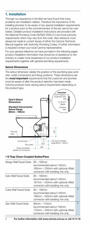
1. InstallationThrough our experience in the field we have found that many problems are installation related. Therefore the importance of the installing plumber to be aware of any special installation requirements for a product prior to the commencement of the job cannot be over-stated. Detailed product installation instructions are provided with the National Plumbing Code AS/NZS 3500.2.2 and local authority requirements which may vary from the code. Also reference must always be made to current issues of either the Caroma Technical Manual together with Authority Plumbing Codes. If further information is required contact your local Caroma representative.For your general reference we have provided in the following pages product installation information that should be of assistance to the industry to create more awareness of our product installation requirements together with general plumbing requirements.
Setout Dimensions
The setout dimension details the position of the plumbing pipe work inlet, outlet connections and fixing positions. These dimensions are the most important requirements that the customer and plumber must be aware of after the product selection has been made. Caroma products have varying setout requirements depending on the product type.
Opal II SetoutDimensions
Standard Uniconnector Setout Range 80mm – 185mm
Important22mm approx.projection from
wall
1/2" B.S.P.Nipple
Finishedwall
Uniconnector 140 recommended range 80mm –185mm
185
260
220
Fixed connectionposition for all setouts
Pan outlet
Pan footlevel
• S-Trap Close-Coupled Suites/Pans
Atrego Wall Faced Suite 80 – 180mm recommended setout 140mm. 180mm – 230mm with optional offset connector with bedding mix only.
Cato Wall Faced Suite 80 – 180mm recommended setout 140mm. 181mm – 220mm with optional offset connector with bedding mix only.
Cube Wall Faced Suite 80 – 185mm recommended setout 140mm. 186mm – 220mm with optional offset connector with bedding mix only.
*
Geo Wall Faced Suite 80mm – 170mm recommended setout 140mm. 170mm – 240mm with optional offset connector with bedding mix only.
*

For further information visit www.caroma.com.au or call 13 14 16 3
Leda Wall Faced Suite
80mm – 180mm recommended setout 140mm. 180mm – 230mm with optional offset connector with bedding mix only.
*
Metro Wall Faced Suite 80 – 180mm recommended setout 140mm. 181mm – 220mm with optional offset connector with bedding mix only.
*
Milan Wall Faced Suite 80mm – 185mm recommended setout 140mm. 186mm – 220mm with optional offset connector with bedding mix only.
*
Neo Wall Faced Suite 80 – 180mm recommended setout 140mm. 181mm – 220mm with optional offset connector with bedding mix only.
*
Opal II and Opal II Easy Height Wall Faced Suites
80mm – 185mm recommended setout 140mm. 186mm – 220mm with optional offset connector with bedding mix only.
*
Opal Suite Wall Faced Suite
80mm – 185mm recommended setout 140mm. 186mm – 220mm with optional offset connector with bedding mix only.
*
Pearl Wall Faced Suite 80mm – 185mm recommended setout 140mm. 186mm – 220mm with optional offset connector with bedding mix only.
*
Senate Wall Faced Suite 80mm – 180mm recommended setout 140mm. 181mm – 240mm with optional offset connector with bedding mix only.
*
Stirling Wall Faced Suite 80mm – 180mm recommended setout 140mm. 181mm – 240mm with optional offset connector with bedding mix only.
*
Atrego Suite recommended setout 140mm adjustable range 80mm – 180mm with optional offset connector.
†
Cameo Suite recommended setout 140mm adjustable range 90mm – 190mm with orbital offset connector.
Caravelle 2000 Suite recommended setout 140mm adjustable range 80mm – 180mm with optional offset connector.
†
Caravelle Easy Height Suite
recommended setout 140mm adjustable range 90mm – 190mm with orbital offset connector.
Regal II Suite recommended setout 140mm adjustable range 100mm – 180mm with optional offset connector.
†
Profile 4 Suite 140mm setout fixed. §
Profile 4 Deluxe Suite recommended setout 140mm adjustable range 100mm – 180mm with optional offset connector.
†
Profile 5 with Integrated Hand Basin Suite
140mm setout fixed. §

4 For further information visit www.caroma.com.au or call 13 14 16
Profile 5 Deluxe with Integrated Hand Basin Suite
recommended setout 140mm adjustable range 100mm – 180mm with optional offset connector.
†
Regal II and Regal Deluxe Suite
recommended setout 140mm adjustable range 100mm – 180mm with optional offset connector..
†
Senate Suite 140mm setout fixed. §
Stirling Suite recommended setout 140mm adjustable range 100mm – 180mm with optional offset connector.
†
* Important: Do not use offset connectors with the supplied Uniconnector when installing these suites. The use of offset connectors may cause the pan to siphon during the flush cycle.
† Important: Use only Caroma performance approved offset connector Code No.687270.
§ Important: These suites are not suitable for offset connectors with an offset greater than 15mm. Even if the offset connector may have Water mark approval it may cause the pan to syphon during the flush cycle, due to a reduction in through-way dimension of the connector. § This note also applies to all suites with Concorde Concealed, Concorde Connector, Cosmo Care, Exposed (Retro), Junior, Trident, Trident Care and Vintage pans. AS 2887 specifies the waterway of the pan connector shall allow the passage of a sphere of diameter 72+0, –1mm.
• S-Trap Pedestal PansThe recommended setout for pedestal pans is 165mm with an adjustable range dependant on the type of cistern used.
• P-Trap Close-Coupled and Pedestal Pan SetoutThe P-trap setout for all close-coupled and pedestal pans is 185mm from the pan foot level.
• Wall Hung Pans Setout DimensionThe setout dimension for a wall hung pan is taken from the finished floor. The bolt hole and inlet positions are critical to the installation. Wall hung pans are suitable for installation with non compressible wall materials only.
Inlet
Finished floor
180Bolt hole centres
Wall contactarea for pan must be true and flat
Outlet
4332
408
213
Setout Dimensions for Cube Pan
155
365
40
Nom
inal
200
Inlet
Outlet
Finished Floor
Setout Dimensions for Walvit Pan
Bolt Hole Centres
210
Wall contact area for panmust be true and flat

For further information visit www.caroma.com.au or call 13 14 16 5
Setout Dimensions for Metro Pan
Inlet
180Bolt HoleCentres
Wall contactarea for pan must be true and flat
Outlet43
32
408
236
Finished floor
• Pedestal and Shrouded BasinsDetailed information is provided on the appropriate basin pages in this manual which will assist in the setting out of bracket fixing positions for noggins and pipe work to clear pedestals/shrouds.
Caravelle 550 Pedestal Setout
7050
Rec
omm
ende
d 86
5
835
appr
ox. D
.200
Fix
ing
Cen
tre
510550
205
435
195
Finishedfloor
280 30
D.200 basin fixing kithole centre positions
220
300*
38
Finished Wall19
516
5
Centre of Basin
40mm DWVPVC or
copper pipe
Basin wasteoutlet
Pedestal
Pedestal Setout Caroma S-trap only
*40mm Caroma Plastic P-trap outlet centre.
Caravelle 550 Shroud Setout
Rec
omm
ende
d 86
5
835
appr
ox. D
.200
Fix
ing
Cen
tre
195
Finished floor
280
30
D.200 basin fixing kithole centre positions
220
280
475
290m
m fr
omfro
nt e
dge
ofsh
roud
380
Hot
& C
old
wat
er in
let c
entre
200shroudwidth
Inlet positionto allow for shroud
80
Yorkshire 1/2" x 1/2" Number 10
300mmFlexible coupling
Shroudinlet detail
280
40
*40mm Caroma Plastic P-trap outlet centre.
To ensure that the pedestal/shroud will conceal the pipe work without interference it is essential that the accurate setout and use of recommended Caroma traps are used for optimum installations.Note: The waste pipe floor position is offset from the waste outlet centre in the pedestal setout.

6 For further information visit www.caroma.com.au or call 13 14 16
• BidetteIt is essential that a Bidette is setout as specified to allow access for plumbing connections and ease of use.The Caroma 40mm short inlet S and P-trap kit (Code No.102119) has been specially developed for use with standard bidettes to ensure the correct floor clearances are maintained for trouble free installation. For Leda bidette use S-trap (Code No.687165) or P-trap (Code No.687164).
Important: All dimensions are to the bidette foot level. It is important to make height allowance for bedding.
Leda Bidette Setout
Concealed Fixing Bracket
Concealed Fixing Bracket
800mm minimum recommendedfor comfortable use
P-trap BidetteFixing KitCode No.687164
S-trap BidetteFixing KitCode No.687165
71
100
225
11513
7
225
P-Trap Setout S-Trap Setout
357
155 22
5
70
610
Pop up wastecontrol knob
365
690mm min. setout
140
70
210
140 min. setout
Royale Bidette Setout
800 mm minimum recommendedfor comfortable use
200
40
Centre line of bidette
Waste pipeposition can be mirrored
50
225
170Finished
Floor
S-trap
P-trap
Royale Bidette Setout Details
40mm short inletS or P-trap
supplied

For further information visit www.caroma.com.au or call 13 14 16 7
Pan Foot Level
The reference point taken from
Pan Foot Level
the level from the under-side of the foot to the relevant height dimension. This height dimension is constant and unaffected by bedding thickness which may vary from our recommendations.
Roughing in
The roughing in is the preliminary stage carried out by the plumber involving the positioning of waste pipe work and water inlet connections before the wall/floor finishes are added. At this stage the plumber must be aware of essential setout requirements and make allowances for wall and floor finishes to determine finished setout dimensions. Liaison must be made with the finishing trade to ensure that essential setout dimensions are achieved. Failure by the plumber to liaise and instruct the finishing trade of the setout requirements and the allowance that has been made for the type of floor/wall finish is the major reason why setout problems occur. At this stage for stud walls, noggins should be posi tioned into the frame for the support of cistern and basin fixings.
Pan/Bidette Fixing
There are two installation methods to fix a pan/bidette to the finished floor either by bedding or screw/bracket fixing.
• Bedding MixAll height dimensions to underside of the foot, make allowance for mortar bedding. The pan should be fixed to the floor with a sand cement mixture of 3:1 to a depth of 60mm. NOTE: Do not use lime or fast drying cement as this may crack the foot of the pan. When bedded the back of the pan should be approximately 10mm above the finished floor.
Cato Pan
Bedding installation Fixing Hole Cover Detail for Bedding Installations(Cato, Cube, Geo, Leda, Metro, Neo, Opal II, Opal II Easy Height and Pearl only)
Level pan when bedding
Pan
hei
ght
Finished floor level
Hei
ght o
f P-T
rap
10mmbeddedposition
BlankingCap
Pan Foot
• Screw/bracket Fixing InstallationThe pan can be fixed directly to the finished floor with either corrosion resistant screws and pan guard washers or the D.80 Concealed bracket where applicable. The pan should be fixed into a bed of silicone sealant.
Bracket Fixing DetailD.80 ConcealedFixing Bracket
Cap
FixingHead
Pan Foot
SiliconeBedding
Threaded Stud
Plastic Sleeve
D.80 Concealed
FixingBracket

8 For further information visit www.caroma.com.au or call 13 14 16
Hei
ght o
f P-t
rap
Level pan whenbedding
Finished floor
185
Finished WallScrew Fixing Installation
Important: Do not use the panscrew holes as a guide for drillingas this may crack the pan. Bedding height
position max. 5mmsilicone around foot.
Position and push pan onto connector
Wall-Hung Pan FixingThe Caroma wall-hung pans have been developed to be fixed to the finished wall using the Invisi II or Sanifix Bracketing Systems. The systems allow for varying wall finishes providing installation flexibility for both structural and non structural walls. The bracket is positioned during the roughing in stage. It is very important that accurate setouts are achieved so that the final installation is according to specification.The installation of wall-hung pans is critical and must be carried out following the installation procedures on the pan carton. This will ensure the function and safety of the installation.When installing wall-hung pans ensure the contact area on the wall for fitting the pan is flat and true. Check with a straight edge before installation.The pan must be secured to the wall with Caroma brackets and fixings. A torque wrench must be used to ensure the bolts are tightened to the required figures in the installation instructions.
• Cube Wall-Hung Pan Installation Detail
Accurate positioning of the waste piperelative to studwork is essential.Cube Wall Hung pan illustrated
Access plateand buttons
Invisi II cistern
90min.
365
cent
re o
f inl
et58
2
947
Finished floor
408
ref
550
213
Integrated isolating valve
supplied
400-420 Frame
45
25
40
6 min. – 45 max.wall thickness
170 max. from finished wallwith Invisi II WH pan connector
For 100mm UPVC DWVconnection use Caroma Invisi II
wall hung waste connector
55 m
in. t
oun
ders
ide
of n
oggi
n
D.403 Invisi II Wall Hung Pan Bracket. Suitable for structural slab or stud wall installation (not supplied).
Note: access to cistern internals can be achievedthrough button plate.
Cube Wall-Hung Pan Fixing Detailwith Invisi II Inwall Cistern

For further information visit www.caroma.com.au or call 13 14 16 9
• Cube Wall-Hung Pan Installation Detail
Cube Fixing Detail
10
SleeveFixing Bush
Pan
StudInlet Kee Seal
Inlet pipeRubberGasket
NotchFacing
Outwards
Inlet
Finished floor
180Bolt hole centres
Wall contactarea for pan must be true and flat
Outlet
4332
408
213
Setout Dimensions for Cube Pan
Inlet Pipe
Inlet KeeSeal
Cube Inlet Detail
FinishedWall
29 Length ofinlet pipefrom finishedwall
Ø100mmWaste Pipe
Stud securedbehind the wall with approved
Caroma bracket
Fixing assembly
38mm Length of Stud fromFinished Wall
40mm
Cube Installation Detail
Caulk withacetic silicone
sealant
Finished wall
StandardPan Collar
RubberGasket
Fixing Bush
10 For further information visit www.caroma.com.au or call 13 14 16
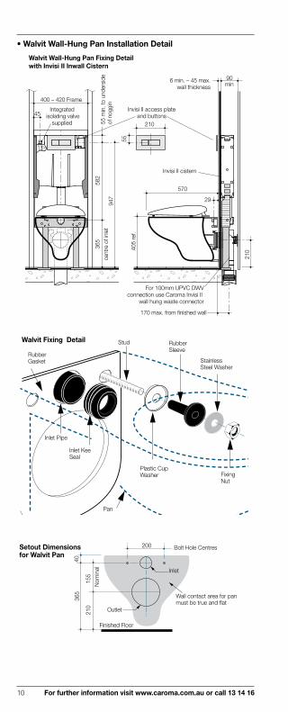
• Walvit Wall-Hung Pan Installation Detail
90min
365
cent
re o
f inl
et58
2
947
Walvit Wall-Hung Pan Fixing Detailwith Invisi II Inwall Cistern
55210
405
ref.
570
210
400 – 420 Frame
45
Invisi II cistern
55 m
in. t
o un
ders
ide
of n
oggi
n
29
6 min. – 45 max.wall thickness
170 max. from finished wallwith Invisi II wall hung pan connector
For 100mm UPVC DWVconnection use Caroma Invisi II
wall hung waste connector
Integrated isolating valve
supplied
Invisi II access plateand buttons
Walvit Fixing Detail
RubberGasket
Stud
Plastic CupWasher
Rubber Sleeve
StainlessSteel Washer
FixingNut
Pan
Inlet KeeSeal
Inlet Pipe
155
365
40
Nom
inal
200
Inlet
Outlet
Finished Floor
Setout Dimensions for Walvit Pan
Bolt Hole Centres
210
Wall contact area for panmust be true and flat

For further information visit www.caroma.com.au or call 13 14 16 11
Inlet Pipe
Inlet KeeSeal
Walvit Inlet Detail
FinishedWall
25 Length ofinlet pipefrom finishedwall
Ø100mmDWV
Stud securedbehind the wall
with suitableCaroma bracket
Fixing assembly
Finished wall Length of Stud fromFinished Wall
Walvit Installation Detail
Caulk withsuitable silicone
rubber compound
55Min.60Max.
Gasket
StandardPan Collar
Cistern Fixing Caroma Cisterns are fixed into position with two methods depending on the model.
• Wall Fixing (Wallmount or Connector type) Fixing holes are provided in the back of the cistern which allows the cistern to be fixed directly to the wall or onto the quick fix bracket.
For stud and non-structural walls noggins, studs or other suitable means of support must be provided during the roughing in stage.
• Direct Pan Fixing (Close Coupled) The Artego, Cato, Cube, Geo, Leda, Metro, Milan, Neo, Opal II, Opal, Pearl, Senate, Stirling, Cameo, Caravelle 2000, Caravelle Easy Height, Profile 4, Profile 4 Deluxe, Profile 5, Profile 5 Deluxe Regal II, Regal Deluxe and Sovereign toilet suites are fixed directly to the pan.
Pan
Cato, Care 800, Cube, Geo, Leda, Metro, Opal II, Opal II Easy HeightOpal, Pearl and Stirling Cistern Fixing
CisternRetaining stud
Foam seal
Artego, Cameo, Caravelle 2000, Milan, Neo, Regal II, Regal Deluxe,Profile 4, Profile 4 Deluxe, Profile 5, Profile 5 Deluxe and SenateCistern Fixing
Wingnut
Cistern
V.C blindwing nut
Cistern boltrubber seal
Foamseal
Cistern
Pan
Capturednut toggle

12 For further information visit www.caroma.com.au or call 13 14 16
Urinal Fixing
The Cube3, Cube H2Zero, Leda, Integra and Torres urinals have been designed to be mounted to appropriate bracketing fixed to the finished wall.For stud and non structural walls noggins, studs or other suitable means of support must be provided during the roughing in stage to fix the urinal brackets.
• Cube3 Urinal Fixing Detail
Finished Floor
80
260
337
Vitreous china grate
665
371
P-t
rap
outle
t cen
tre45
858
Inle
t Cen
tre
*
615
appr
ox.
D.1
67 C
once
aled
Fix
ing
Bra
cket
* 610 recommended standard height 400 recommended disabled height
50mm PVC DWV orCopper DWV
2° Slope
26 Nominal 20mmsparge brass pipe(not supplied)
35
2 Kee Seals supplied to suit PVC or CopperDWV outlet connection
D.167 Concealed Fixing Bracket(wall fixings not supplied)
Plastic Cap
FixingStud
Plastic Sleeve
371
P-t
rap
outle
t cen
tre
9252
40
Plastic Waste Trap
Roughing in for Bracket and Trap Positions
20Centre of Urinal
615
appr
ox.
D.1
67 C
once
aled
Fix
ing
Bra
cket
80

For further information visit www.caroma.com.au or call 13 14 16 13
• Cube H2Zero Urinal Fixing Detail
26033
3
600
appr
ox.
D.1
67 C
once
aled
Fi
Bra
cket
80
600
* 610 recommended standard height 400 recommended disabled height
Waste Connector Assembly(Wall fixing screws not supplied)
Roughing in for Bracket and Waterless Cartridge Installation
Finished Floor
Waste Connector
D.167 ConcealedFixing Bracket
50mm PVC DWV
Drain outlet5˚ slope
395
outle
t cen
tre w
ith5˚
slo
pe to
wal
l
135
3518
50mmPVC DWV
600
appr
ox.
D.1
67 C
once
aled
Fix
ing
Bra
cket
80
D.167 Concealed Fixing Bracket(wall fixings not supplied)
Plastic Cap
FixingStud
Plastic Sleeve
Specially designed tool for Bio SealTM and Bio Fresh replacement
Waterless Cartridge
Vandal ResistantMetal Grate
Replaceable Bio Fresh Block
Replaceable Bio SealTM
Waste Body
Waterless Cartridge
Code DescriptionH2Zero Cartridge Tool
687332 H2Zero Cleaning Liquid (5L)687334 H2Zero Replacement Service Kit
(10 x BioFresh and 10 x BioSeal)687335 H2Zero Cartridge Tool and
Replacement Cap Kit
687341 H2Zero BioFresh (pack of 20)
687299

14 For further information visit www.caroma.com.au or call 13 14 16
• Leda Urinal Fixing Detail
355
540
315
882
597
D.1
70 C
once
aled
fixi
ng B
rack
et c
entre
*
650 recommended height400 recommended disabled height
*
80 o
ulte
t cen
tre37
9 S
tand
ard
129
Dis
able
d
438
6535
Vitreous ChinaGrate
P-trap roughingin for waste pipe
50 or 40mm Brass pipework or 40mm PVC DWV.Kee seal available for50mm brass option
18 19mm spargeBrass pipe(not supplied)
10
80
597
D.1
70 C
once
aled
Fix
ing
Bra
cket
cen
tre
86
817
65
537
379
Cen
tre o
f out
let
to th
e flo
or
118
10mm offset
86
Centreof Urinal
118
IMPORTANT
Roughing in for Bracket and Trap positions
Wall Waste Pipe installation – supplied with P-trap UrinalSuitable for connection to 50mm Brasswaste pipe (separate Kee Seal required)and 40mm Brass or 40mm PVC SWV
Plastic Siphonic P-trap D.170 Concealed Fixing Bracket(wall fixings not supplied)
Plastic Cap
Fixing Stud
Fixing Head
Plastic Sleeve

For further information visit www.caroma.com.au or call 13 14 16 15
• Integra Urinal Fixing Detail
365
365
Bra
cket
Fix
ing
265
648
385
465
495
Sta
ndar
d28
5 D
isab
led
33
150
Back inlet
Out
let c
entre
D775 Concealedfixing bracket
Vitreous china grate
610
reco
mm
ende
d st
anda
rd h
eigh
t40
0 re
com
men
ded
disa
bled
hei
ght
**
5° Slope
90
Waste pipeØ50 O.D. Brass orØ50 I.D. – P.V.C.
Two Rubber Seal optionsare provided
183
175 Bracket fixing
Recommended height from floor tobracket fixing centre:Standard – 445mmDisabled – 235mm.
Urinal inlet pipeD.775 ConcealedFixing Bracket
D.775 ConcealedFixing Bracket
1/2/15x14 T.P.I.pipe thread
Inlet Pipe Detail
Sliding wedge
Brass TieHook
Brass wingnutand washer
Sparge Pipe
Wedge adjustmentand Tie Hook Detail
Adjustmentscrew
Inlet Seal

16 For further information visit www.caroma.com.au or call 13 14 16
• Torres Urinal Fixing Detail
425
390
90
Domed outletgrating
Adjustablespreader
720 48
5 53
5 S
tand
ard
325
Dis
able
d
25
Out
let c
entre
610mm recommended standard height.400mm recommended disabled person.
Alternative top inletuse D.300 top inlet tie
Back inlet use D.301sparge pipe bracket
Finished floor
500
* *
30
145
Waste pipeØ50 O.D. Brass orØ50 I.D. – P.V.C.
Two Rubber Seal optionsare provided
Trap outlet5° slope
• Top and Back Inlet Setouts and Fittings
Fig.1: D.300 Top Inlet Sparge Pipe Urinal Assembly
25
25
Fig.1
75
250 590
45
Soil Outlet Pipe
M12x4
5˚ Slope on Soil Outlet
30
C L
D.232 Support Bracket x 2
85
Rubber Kee Sealprovides water tight seal for Ø50mm O.D. Pipe
M8 x 2
Cover to besecured towall with loxins
Sparge Pipe
*
75
Flush PipeFlush Pipe Nut
SealSparge Pipe Nut
CoverLock Nut
Spacer WedgeSleeve
Sparge Pipe
Lock Nut
Fibre WasherSleeve
Lock Nut
Water Spreader
Socket Set-Screw
Top Inlet Setout Dimensions
610mm recommended standard height. 400mm recommended disabled person.
*

For further information visit www.caroma.com.au or call 13 14 16 17
Fig.1120
250
485
7545
SoilOutletPipe
M12x4
5˚ Slopeon SoilOutlet30
CL
D.232 SupportBracket x 2
85
Inlet Pipe
M8x2
*
Rubber Kee Sealprovides water tight seal for Ø50mm O.D. Pipe
610mm recommendedstandard height.400mm recommended disabled person.
*
Torres Urinal Back Inlet Setout Dimensions
Fig.1: D.301 Back Inlet Sparge Pipe Assembly
D301 Bracket
Sparge Pipe
SleeveLock Nut
SocketSet-Screw
Water Spreader
15 / 20
Fix D.301 bracket to wall with Loxins
• Urinal Brackets and Fittings
Locks into wall
D.232 Bracket
Spigot Screw
Urinal
Lock Nut
Wall
Adjustment
D.232 Support Bracket
Grate Fixing
Tighten screwto secure
To adjust, remove set-screw and chrome cover. Turn adjuster left or right to control water sparging action. Replace chrome cover and set screw.NOTE: Use thread-sealing tape where required.
Adjustable Water Spreader
AdjusterChrome Cover
Set-screwTorres Urinaltop and back watersupply inlet

18 For further information visit www.caroma.com.au or call 13 14 16
Wall Basin Fixing
All plumbing work for the water and waste pipe connections for the basin is positioned during the roughing in stage.For timber stud and non-structural wall noggins or other suitable means of support must be built for the basin bracket at the recommended height.
Basin Taphole Size Configurations
Ø34.0 + 2.0 0.0Ø28.0 + 2.0
0.0Ø34.0 + 2.0 0.0
Three Tapholes One Taphole
• Pedestal Wall Basin FixingFor the fixing of basin brackets to timber stud walls the noggins must be positioned at the specified height to allow for the location of fasteners at the detailed bracket fixing positions. The bracket centre fixing positions are detailed as the following typical drawings show on the specific wall basin product. Check setout with pedestal and basin to determine bracket wall mounting position.
835
appr
ox. D
.200
Fix
ing
Cen
tre
280
D.200 basin fixing kithole centre positions
D.200 Basin Fixing Kit
Caravelle 550 Basin Fixing
D.200 Basin Fixing Kit: Bolts directly to finished wall.

For further information visit www.caroma.com.au or call 13 14 16 19
• Shroud Wall Basin FixingD.210 Concealed Fixing Clip: suitable with D.200 bracket and 40mm Caroma plastic P-trap. Note: it is essential for the installation of the shroud to the basin that clearance is provided for the shroud in the plumbing setout from water inlet pipes and connections.
Rec
omm
ende
d 86
5
835
appr
ox. D
.200
Fix
ing
Cen
tre
195
Finishedfloor
280 30
D.200 basin fixing kithole centre positions
220
280
475
290m
m fr
omfro
nt e
dge
ofsh
roud38
0 H
ot &
Col
dw
ater
inle
t cen
tre
200shroudwidth
Inlet positionto allow for shroud
80
Yorkshire 1/2" x 1/2" Number 10
300mmFlexible coupling
Shroudinlet detail
300*
40
D.210 Concealed Fixing Clip Assemblyincluded with Shroud
Caravelle 550 Basin and Shroud Fixing
*40mm Caroma Plastic P-trap outlet centre. 290mm for Shroud installations withChrome covered waste
Concealed Fixing Bracket: Bolts to wall and secures Geo/Liano shroud in position. Use 40mm Caroma plastic P-trap. Note: it is essential for the installation of the shroud to the basin that clearance is provided for the shroud in the plumbing setout from water inlet pipes and connections.
Concealed Fixing Bracketincluded with Shroud
D.200 basin fixing kithole centre positions
Geo 500 Basin and Shroud Fixing
Inlet positionto allow for
shroud
320
Hot
& c
old
wat
er in
let
cen
tre
385
717
appr
ox. C
once
aled
Fi
Bra
cket
cen
tre
80M & F 1/2"
brass elbowwith shroud
only
Flexiblecoupling
220
320
160
230
D.2
00 F
ixin
g ce
ntre
s81
5 ap
prox
. with
Shr
oud
Rec
omm
ende
d 86
5
*
Finished Floor
* For Shroud installations with Chrome covered waste
Plastic Cap
Fixing Stud
Plastic Sleeve

20 For further information visit www.caroma.com.au or call 13 14 16
Vanity Basin Fixing
Vanity basin rims must be sealed to the counter top with an acetic cured silicone sealant. Epoxy type glues must not be used as this may lead to cracking of the basin in granite and marble vanity tops.
Basins supplied with a template which must be used for the counter top cut-out.
• Over Counter Basins.
Counter top
Counter top
170
Vanity Basin
Caravelle 600 Vanity Basin Fixing IMPORTANT: Use only an acetic cured silicone sealant.Epoxy type glues must not be used.
• Under Counter Basins.
Counter top
215
Countertop
Cabinet Fixing
Alloy Bracketfor woodencounter tops
12
Marble Top
Fix timber blocks to top with 2 part epoxy
Aluminium clip bracketfor marble and granite counter tops
2 x Gauge 10 pan head
screws (20mm)
Ensure fixingbrackets areclear of bowl
IMPORTANTUse only an acetic cured silicone sealant.Epoxy type glues must not be used.
IMPORTANTUse only an acetic cured silicone sealant.Epoxy type glues must not be used.
VanityBasin
Caravelle 600 Under CounterVanity Basin Fixing
Vanity Basin
Marble Top Fixing
Four Aluminium Clip Brackets (supplied with basin) for fixing basin to marble or granite counter tops.
Four Alloy Brackets (not supplied) are for fixing basin to wooden counter tops. The rim of the basins must be sealed to the underside of the counter top with an acetic cured silicone sealant. Epoxy type glues must not be used.
Basin supplied with a template which must be used for the counter top cut-out.

For further information visit www.caroma.com.au or call 13 14 16 21
• Semi Recessed Basins.
25022017
0
30
205
300mm or 330mm when using D.251 Heavy Duty Bracket,variable when using D.250 Tie Brackets.Note: Local authorities have requirements forminimum basin to wall dimensions.
570
470
20mm max.apron thickness
170
143
7530
163m
m m
in. a
pron
Laser Semi Recessed Vanity Basin
Basin A Apron
A
Caravelle 600 160 180
Caravelle 550 158 178
Carboni II 90 170
Concorde 500 155 175
Cosmo 150 175
Geo 120 168
Laser 143 163
Leda Vasque 110 130
Liano 105 125
Milan 150 170
Opal Sole 67 135
Pearl 102 150
Cut-out templates are supplied with each basin and must be used.
The rim of the basin must be sealed to the top and front section with an acetic cured silicone sealant.
Tie hook assembly
M8 fasteners into wall
Waste tie assembly
M4 suitablescrews into soffit
of counter (not supplied)
D.250 Bracket with Tie Hooks
D.251 Galvanised Metal Frame and Waste Tie
Brass Wingnutand Washer
Tie Hook
D.250 Bracket with Tie Hooks: Two brackets are fixed to the underside of the counter top to secure the tie hooks which anchor the back of the basin to the counter top.
D.251 Galvanised Metal Frame and Waste Tie: Recommended for wall hung counter top and heavy duty commercial applications, incorporates tie hooks and waste tie assembly.

22 For further information visit www.caroma.com.au or call 13 14 16
Pressed Steel Bath Fixing
• Stirling/Shark and Mayfair Shower Bath Built in bath installations
1. Protect the bath from accidental damage in handling and installa-tion. Check the porcelain enamel surface carefully on removal of packaging materials prior to and again after installation.
2. Accurate setout for the bath waste is essential. Set out the pipe work for the bath and check the alignment with the waste before installation.
3. Build in the bath support structure as detailed below for timber, steel or masonry installations and grade bath sub-floor to local Authorities requirements.
4. The bath must be supported continuously and evenly under the entire rim and the bath rim support must positively locate the bath, plumbing connections must not be used to restrain the bath against movement. (See detail below).
5. Metal Pipe work Installation: To avoid damage to the porcelain enamel surface forces must not be applied to the bath by exces-sively rigid pipe work or misaligned pipe work. Do not support the bath with the pipe work. Metal waste pipe work must incorporate a suitable flexible coupling equivalent to that shown in detail below which will accommodate a slight misalignment. For trap installations above the floor level ensure that the bottom of the trap or pipe work has a minimum 10mm clearance from the floor level below the bath. (See detail below).
6. Plastic waste pipe work Installation: To avoid damage to the porcelain enamel surface forces must not be applied to the bath by excessively rigid pipe work or misaligned pipe work. Do not support the bath with the pipe work. Plastic waste pipe work must be unrestrained for a length of 300mm from the waste outlet fitting or a flexible coupling used. (See detail below). For trap installations above the floor level ensure the bottom of the pipe work has a 10mm clearance from the floor. (See detail below).
7. Before enclosing and tiling the bath, ensure that all the connec-tions and pipe work are watertight. Ensure that the bath drains fully prior to completion of installation. The air space beneath the bath should be ventilated to the requirements of local Authorities.
8. Apply an approved flexible sealant to all exposed edges.9. Enclose and tile in bath.
Cleaning and Maintenance.Use only neat detergent or non-abrasive cream cleanser as recom-mended by the manufacturer for porcelain enamel. Apply on a soft cloth and hand rinse clean. If the bath has an optional “Sure Step” surface, clean it with a stiff polyester or nylon brush as well as with liquid cleaning detergents.After cleaning the bath or adjacent tiles, or using bath salts, always rinse the bath clean with water to remove any chemical residues.Do not use an abrasive cleaner to remove surface grime.Note: Caroma products, treated with care, will ensure many years of satisfactory service. Avoid contact with sharp objects and do not drop heavy or hard objects onto the surface. Always fill the bath before the addition of acidic / or alkaline bath salts.
Stud
Timber frame
Built-in Bath Installation Timber Frame

For further information visit www.caroma.com.au or call 13 14 16 23
Tiles
Suitable moisture barrier
Installation Detail for Built-in Baths
Optionaloverflow position
80
Timber or Steel Stud Wall Installation
Nogging tosupport tiling
substrate.
Notch stud 25mm max.Where notching of studwork
is not permitted the bath is tobe supported as per detail
for masonry walls.
StudBatten to support rim in
all built-in sections of bathsurround.
5mm gap
Bath
Bath
Flexible sealant
Wall tiles
Approved wetarea sheeting
Wall tiles
Flexible sealantMasonrywalls
Batten securelybolted to wall
Batten securelybolted to Stud
Masonry Wall Installation Timber or Steel FrameSupport Installation
Approved wetarea sheeting
Top plate
Bath
Bottom Stud
Wall tiles
Timber to comply with AS1684
300mm
Allow 10mmminimum clearance
IMPORTANT NOTICE FOR INSTALLATIONS:1. Clearance must be maintained under the bath to allow free flexing of the entire bottom of the bath or shower.2. Do not use offset connectors.3. Ensure no misalignment of waste fitting that may cause twisting of the bath waste. (ie there are no vertical forces acting on the waste pipe connecting to the bath).4. Compliance with AS.3740 Waterproofing of wet areas within residential buildings applies when installing baths.

24 For further information visit www.caroma.com.au or call 13 14 16
Flexible Coupling Assembly Detail A
10mmclearance
Bath Compatible sealant
Flexible thrust washerBack nut
Approved brass or plastic waste outlet fitting
Authorised brass or plastic expansion coupling
Copper or plasticwaste outlet pipework
Flexible coupling assembly eg. Iplex Code 06340. Harbic Brass Codes 01052 (Brass), 01053 (Chrome), 01054 (Gold).
Note: Wrap with suitable material to protect coupling and pipework if exposed to debrior immersion in concrete.
10mm clearance
Bath
Compatiblesealant
Flexible thrust washer
Assembly Detail C
Assembly Detail B
300 unrestrained
to common trap
Approved brassor plastic wasteoutlet fitting
clearance
Bath
Compatiblesealant
Approved brassor plastic wasteoutlet fitting
10mm
Flexible thrust washer
For further information visit www.caroma.com.au or call 13 14 16 25
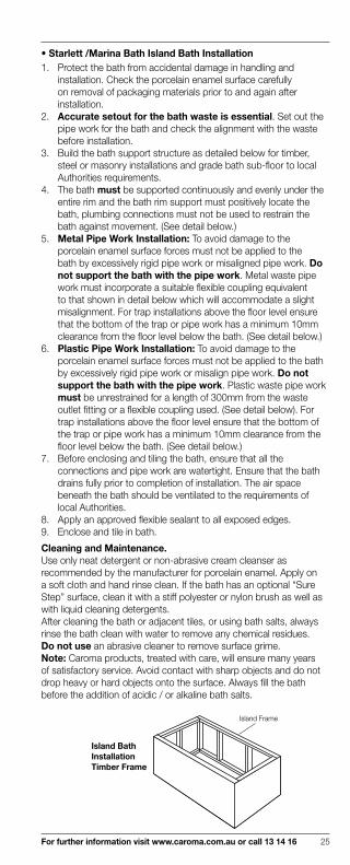
• Starlett /Marina Bath Island Bath Installation 1. Protect the bath from accidental damage in handling and
installation. Check the porcelain enamel surface carefully on removal of packaging materials prior to and again after installation.
2. Accurate setout for the bath waste is essential. Set out the pipe work for the bath and check the alignment with the waste before installation.
3. Build the bath support structure as detailed below for timber, steel or masonry installations and grade bath sub-floor to local Authorities requirements.
4. The bath must be supported continuously and evenly under the entire rim and the bath rim support must positively locate the bath, plumbing connections must not be used to restrain the bath against movement. (See detail below.)
5. Metal Pipe Work Installation: To avoid damage to the porcelain enamel surface forces must not be applied to the bath by excessively rigid pipe work or misaligned pipe work. Do not support the bath with the pipe work. Metal waste pipe work must incorporate a suitable flexible coupling equivalent to that shown in detail below which will accommodate a slight misalignment. For trap installations above the floor level ensure that the bottom of the trap or pipe work has a minimum 10mm clearance from the floor level below the bath. (See detail below.)
6. Plastic Pipe Work Installation: To avoid damage to the porcelain enamel surface forces must not be applied to the bath by excessively rigid pipe work or misalign pipe work. Do not support the bath with the pipe work. Plastic waste pipe work must be unrestrained for a length of 300mm from the waste outlet fitting or a flexible coupling used. (See detail below). For trap installations above the floor level ensure that the bottom of the trap or pipe work has a minimum 10mm clearance from the floor level below the bath. (See detail below.)
7. Before enclosing and tiling the bath, ensure that all the connections and pipe work are watertight. Ensure that the bath drains fully prior to completion of installation. The air space beneath the bath should be ventilated to the requirements of local Authorities.
8. Apply an approved flexible sealant to all exposed edges.9. Enclose and tile in bath.
Cleaning and Maintenance.Use only neat detergent or non-abrasive cream cleanser as recommended by the manufacturer for porcelain enamel. Apply on a soft cloth and hand rinse clean. If the bath has an optional “Sure Step” surface, clean it with a stiff polyester or nylon brush as well as with liquid cleaning detergents.After cleaning the bath or adjacent tiles, or using bath salts, always rinse the bath clean with water to remove any chemical residues.Do not use an abrasive cleaner to remove surface grime.Note: Caroma products, treated with care, will ensure many years of satisfactory service. Avoid contact with sharp objects and do not drop heavy or hard objects onto the surface. Always fill the bath before the addition of acidic / or alkaline bath salts.
Island Bath Installation Timber Frame
Island Frame

26 For further information visit www.caroma.com.au or call 13 14 16
Starlett Hob Installation
Tiles
Suitablemoisture barrier
300mm
385m
m
Tiles
32
Marina Hob Installation
MarinaHob Installation
TilesOptionaloverflow position
80
Suitablemoisture barrier
Starlett Floor Installation
423
Optional overflow position
80
75mm min.
Flexiblesealant
Tiling
Wall
Bath
Tilingsubstrate
Timber frame to support bath rim and tiles all round
Island Installationfor floor mounted bath
75mm min.
Flexiblesealant
Tiling
Wall
Bath
Tilingsubstrate
Timber or steel frame to support bath rim all round
Island Installationfor hob mounted bath
300mm
Allow 10mmminimum clearance
Tiling Granite or marble
WallBath
Flexiblesealant
Timber or steel frame to support bath rim all round
Granite and Marble Installations (not for spa bath installations)
IMPORTANT NOTICE FOR INSTALLATIONS:1. Clearance must be maintained under the bath to allow free flexing of the entire bottom of the bath or shower.2. Do not use offset connectors.3. Ensure no misalignment of waste fitting that may cause twisting of the bath waste. (ie there are no vertical forces acting on the waste pipe connecting to the bath).4. Compliance with AS.3740 Waterproofing of wet areas within residential buildings applies when installing baths.
For Granite or Marble InstallationsThe granite or stone should be independently supported, and at no time should the granite come in contact with the bath.
Allow 10mmminimum clearance

For further information visit www.caroma.com.au or call 13 14 16 27
Flexible Coupling Assembly Detail A
10mmclearance
Bath Compatible sealant
Flexible thrust washerBack nut
Approved brass or plastic waste outlet fitting
Authorised brass or plastic expansioncoupling
Copper or plasticwaste outlet pipework
Flexible coupling assembly eg. Iplex Code 06340. Harbic Brass Codes 01052 (Brass), 01053 (Chrome), 01054 (Gold).
Note: Wrap with suitable material to protect coupling and pipework if exposed to debrior immersion in concrete.
10mm clearance
BathCompatiblesealant
Flexible thrust washer
Assembly Detail C Starlett
Assembly Detail B Starlett 300 unrestrained
to common trap
Approved brassor plastic wasteoutlet fitting
clearance
BathCompatiblesealant
Approved brassor plastic wasteoutlet fitting
10mm
Flexible thrust washer
10mm clearance
Bath
Compatiblesealant
Flexible thrust washer
Assembly Detail C Marina
Assembly Detail B Marina 300 unrestrained
to common trap
Approved brassor plastic wasteoutlet fitting
clearance
Bath
Compatiblesealant
Approved brassor plastic wasteoutlet fitting
10mm
Flexible thrust washer

28 For further information visit www.caroma.com.au or call 13 14 16
Acrylic Bath Fixing
1 Grade bath sub floor to local Authorities requirements.2 Built-in Installations: Recess 50x25 support battens the full
length of bath in wall (see detail). Island Installations: Baths are suitable for island installations (see detail).
3 Remove protective film from tiling bead and waste before installation, and remove the remaining film on completion.
4 Bath Support: The design and rigidity of the Caroma baths allows for installation without a mortar bed. The base of the baths can simply be supported with three timber supports as detailed.
5 Ensure under bath area is ventilated to the requirements of local authorities.
6 Leave “Cleaning and Maintenance Instructions” label in a position for the householder to read.
Note: All materials to appropriate Australian Standards.
Shape bricks to cleararm rest
Tiles
Ø12 copper run off tube
50x25Timberbatten
Suitable moisture barrier
Unfinished floor
Standard 40mmwaste outlet
Black line indicatorsof wooden support
On the indicator lines, position and fix timber supports to base of the bath and floor with an approved floor and wall paneling adhesive or equivalent adhesive to provide a neat fit support . Ensure the rim of the bath is levelled during this procedure.
Floor
Gradesubfloor
1:60 min. orto local
authorityrequirement
Mortar Bed Detail
Acrylic Bath Support Details
Shape bricks to clear side of bath if required
Tiles
Mortar
Bath supportbed mix 3:1
Ø12 copperrun off tube
Grade subfloormin.1:60
Suitable moisturebarrier
Unfinished floor
Standard 40mm waste
outlet25 m
in.
thic
k be
d
Supportframe
IMPORTANT:For slab floors allow access to connectwaste outlet from side of bath after bedding
50x38 framing50
19
50x25batten
Compressed cement fibre sheet backing
Tiling
Stud
Tiles
Wallboard
Timber Support Alternative
Built-in Installation
Sealant
Compressedcementfibre sheetbacking
Tiling
Stud
Island Installation
75mm min.
IMPORTANT: Refer to Local Authority for minimum setout from wall
Sealant
10
*
For further information visit www.caroma.com.au or call 13 14 16 29
2 Pans
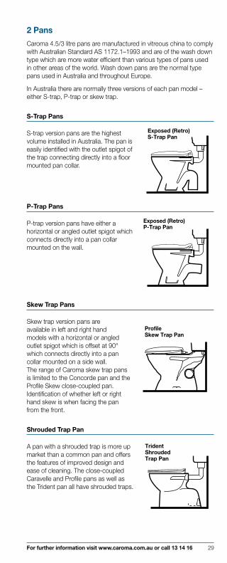
Caroma 4.5/3 litre pans are manufactured in vitreous china to comply with Australian Standard AS 1172.1–1993 and are of the wash down type which are more water efficient than various types of pans used in other areas of the world. Wash down pans are the normal type pans used in Australia and throughout Europe.
In Australia there are normally three versions of each pan model – either S-trap, P-trap or skew trap.
S-Trap Pans
S-trap version pans are the highest Exposed (Retro)S-Trap Pan
volume installed in Australia. The pan is easily identified with the outlet spigot of the trap connecting directly into a floor mounted pan collar.
P-Trap Pans
P-trap version pans have either a Exposed (Retro)P-Trap Pan
horizontal or angled outlet spigot which connects directly into a pan collar mounted on the wall.
Skew Trap Pans
Skew trap version pans are ProfileSkew Trap Pan
available in left and right hand models with a horizontal or angled outlet spigot which is offset at 90° which connects directly into a pan collar mounted on a side wall. The range of Caroma skew trap pans is limited to the Concorde pan and the Profile Skew close-coupled pan. Identification of whether left or right hand skew is when facing the pan from the front.
Shrouded Trap Pan
A pan with a shrouded trap is more up TridentShroudedTrap Pan
market than a common pan and offers the features of improved design and ease of cleaning. The close-coupled Caravelle and Profile pans as well as the Trident pan all have shrouded traps.

30 For further information visit www.caroma.com.au or call 13 14 16
Close-Coupled Suite
A suite where the pan and the Caravelle 2000 Close CoupledSuite
cistern are usually joined together with the flush pipe concealed. The majority of Caroma products are close-coupled in either vitreous china or plastic cistern versions.
Wall Faced Pan
A pan which can be installed with LedaWall Faced Pan
the back face of the pan fitting directly against the finished wall. Wall faced pans are used widely for commercial and up market domestic applications offering ease of cleaning and improved design.
Wall-Hung Pan
A wall-hung pan bolts directly to the finished wall, clear of the floor surface for ease of cleaning. This feature makes the pan ideal for use in commercial application. The installer must be aware of the critical installation requirements. Available in P-trap only.
Boxed Rim Pan
A boxed rim pan has a closed water rim with inlet holes around the underside of the rim directing water into the bowl of the pan. These pans are quieter in operation than open rim pans and are more versatile with accommodating cisterns of varying head height without splashing problems, the Leda and Walvit pans are boxed rim type
Open Rim Pan
A open rim pan has a flushing rim which is open and directs water to the front of the pan allowing water to fall freely over the bowl to wash the surfaces.
WalvitWall-Hung Pan
For further information visit www.caroma.com.au or call 13 14 16 31
3 CisternsAll Caroma Cisterns are manufactured in either vitreous china or plastic to comply to Australian Standard AS1172.2 and are of the underwater valve type. Note: The majority of water authorities require 3 to 4 star WELS rated dual flushing volumes for matched pans and cisterns. Check with your local authority before specifying single flushvalve or cistern installations.
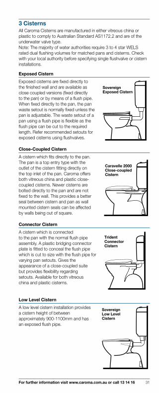
Exposed Cistern
Exposed cisterns are fixed directly to SovereignExposed Cistern
the finished wall and are available as close coupled versions (fixed directly to the pan) or by means of a flush pipe. When fixed directly to the pan, the pan waste setout is normally fixed unless the pan is adjustable. The waste setout of a pan using a flush pipe is flexible as the flush pipe can be cut to the required length. Refer recommended setouts for exposed cisterns using flushvalves.
Close-Coupled Cistern
A cistern which fits directly to the pan.
Caravelle 2000Close-coupledCistern
The pan is a top entry type with the outlet of the cistern fitting directly on the top inlet of the pan. Caroma offers both vitreous china and plastic close- coupled cisterns. Newer cisterns are bolted directly to the pan and are not fixed to the wall. This provides a better seal between cistern and pan as wall mounted cistern seals can be affected by walls being out of square.
Connector Cistern
A cistern which is connected TridentConnectorCistern
to the pan with the normal flush pipe assembly. A plastic bridging connector plate is fitted to conceal the flush pipe which is cut to size with the flush pipe for varying pan setouts. Gives the appearance of a close-coupled suite but provides flexibility regarding setouts. Available for both vitreous china and plastic cisterns.
Low Level Cistern
A low level cistern installation provides SovereignLow LevelCistern
a cistern height of between approximately 900-1100mm and has an exposed flush pipe.

32 For further information visit www.caroma.com.au or call 13 14 16
Mid Level Cistern
A mid level cistern installation provides
SlimlineMid LevelCistern
a cistern height of approximately 1300mm and has an exposed flush pipe. Mid level installations are being phased out in favour of the more acceptable close-coupled and low level installations. Now mainly required for replacement applications.
Back Inlet Cistern
The water inlet connection for a back inlet cistern is from the wall directly into the back of the cistern. The connection is completely concealed and has an integral stop valve. The Cube, Leda 2000, Geo and Opal 11 suites are standard as back inlets, with Caravelle 2000 suite being optional.
Bottom Inlet Cistern
Water connections are to the underside of the cistern via an exposed stop cock. Right hand versions, convertible to left hand are available in most cistern models. This is the standard inlet connection system used throughout Australia.
Inwall Cistern
The inwall cistern is fitted into the
Invisi IIInwall Cistern
wall cavity with access to service the cistern via a cover panel. The Invisi II inwall cistern fits into a wall cavity of 90mm and is available in single or dual flush. Flushing buttons can be up to 4 metres from the cisterns when connected to an extended pneumatic tube.
Induct Cisterns
The induct cistern is fitted into the service duct behind the pan with an access to the cistern via the duct. Two models are available in the Caroma range, Invisi II and Slimline induct cisterns.
Under Counter Cisterns
The under counter cistern is fitted under the vanity counter. The Invisi II Under Counter, Slimline Induct and Compact Under Counter cisterns are available in the Caroma range.
Inceiling Cisterns
The inceiling cistern is fitted into the ceiling cavity with access to the service via a ceiling panel. Due to the flushing head height use only box rim type pans. The remote push button Invisi II and Invisi inceiling cisterns are available for this application.

For further information visit www.caroma.com.au or call 13 14 16 33
Flushvalves
The Schell WC flushvalve is designed to be connected directly to the mains pressure potable water supply. Confirmation of this should be made with local authority prior to commencement of installation. The valve allows for the system to be repeatedly flushed with no fill time required making the flushvalve ideal for commercial installations with inwall, induct and inceiling models available.Consideration should be given to the engagement of a hydraulic consultant or engineer for the design of pipelines to multiple flushvalve installations, as there are special reticulation requirements.• Pipe work to the valve minimum diameter of 25mm.• Minimum static pressure of 20 metres head pressure at the valve.• Flow pressure range of 20 to 50 metre head.• Minimum flow pressure 1.4 litres per second flow pressure at the valve. Recommend 2 litres per second at the valve.Failure to provide any or all of the above requirements may cause malfunction of the valve whether a single or multiple valve installation.
Inlet Valve
Controls the delivery of water into the cistern. A super quiet fast fill inlet valve is available with some cistern models.There are two types of inlet valves available with Caroma cisterns:
Quietflow 2 Inlet Valve
Provides proven trouble
WL
CL
free performance.Inlet valves can be changed from left to right or conversely depending on position of water inlet connection.
Outlet Valve
The outlet valve when activated controls the volume of water delivered from the cistern to the pan. The majority of Caroma cisterns are available as standard with Caroma Smartflush 4.5 litre dual flush outlet valves. M5 Outlet Valve

34 For further information visit www.caroma.com.au or call 13 14 16
4 Bidette A bidette is used to wash personal areas of the body and provides greater hygiene benefits to the user. Available with over the rim spray which provides an air gap and therefore can be connected directly to the mains potable water supply.
5 Slophopper A slophopper is used to discharge waste materials and is mainly used in hospitals (bedpan discharge), and functions in a similar manner to a WC pan and is available in S and P-trap options for pedestal pans and P-trap for wall-hung model.
6. Caroma Care
Caroma care is a range of access products for accessible applications and ambulant people. Detailed are basin and toilet suite installations which comply to AS 1428-1. The building code of Australia now requires all commercial installations for disabled people comply to AS 1428-1. Refer to appropriate Product section for full specifications.
Important: Reference must be made to AS 1428-1 with current amendments to determine circulation space, grab rail and installation requirements. The dimensions may change with amendments to the standard.
Slophopper
RoyaleBidette
Over rim spray

For further information visit www.caroma.com.au or call 13 14 16 35
7 Hydraulic History
Background History
Until the 1950’s, Plumbing and Drainage systems in Australia reflected historical and business ties with the UK.
The post-war building boom gained momentum and in the 50’s and early 60’s giving the commercial pressures for modern systems. These also saved space, used new materials and as a result a move away from the practices of the UK was evidenced.
There were a number of noted researchers, mathematicians and engineers examining the previous and current systems, amongst whom were Dr R B Hunter of the USA in the post World War I era and later Mr A Wise of the UK Building Research Station.
These men, and others, established new systems basing their work on mathematics as applied to fluids and gaseous volumes and Dr Hunter propounded the Theory of Probability upon which much of our present day services are based. Dr Hunter and others became increasingly aware that sanitary plumbing and drainage lines are subjected to their maximum carrying capacity for an incredibly small amount of time. This situation occurs only when multiple fixtures discharge waste water into a pipeline section at precisely the same or over-lapping time.
To assist researchers a measurement of volume known as a “Fixture Unit” was allotted to each sanitary fixture to give an individual and progressive “in line” Fixture Unit Rating. His work on the water supply reticulation was also based upon the Theory of Probability and fixture unit ratings for water flow to various fixtures.
Broadly the present pipe sizing of our sanitary plumbing/drainage systems find their origins in the Theory of Probability and the Fixture Unit Ratings.
The earlier Researchers by mathematical formulae and practical tests established suitable pipe sizes commensurate to pipe loadings. The Researchers and subsequently many others found that the free flow of air above the mass of water in a horizontal sanitary plumbing pipeline or in a centre of the falling volume of water of a vertical stack was the key in providing a safe sanitary plumbing system.
The periodical build up of water to a situation where the entire pipe diameter is filled is the ‘problem’ period which if not offset by correct venting will lead to the loss of trap seal due to either Self Siphonage or Induced Siphonage. The loss of trap seal from any cause, resulting in sewer gasses entering a room can be also defined as a ‘System Failure’ and must be avoided.
In most sanitary plumbing systems some minor loss of trap seal depth will be experienced due to the action of pressures within the system (usually referred to as ‘Waving Out’). For this reason the trap depths are normally 75mm for normal line trap whereas fixture traps, WC pans, slophoppers, are the earlier depth of 50mm. This minor loss is acceptable and has been provided for in the trap dimensions. Attention to venting details of the system is critical to its success.

36 For further information visit www.caroma.com.au or call 13 14 16
8 Plumbing Terms and Definitions1 PlumbingIncorporates services such as sanitary plumbing, cold and hot water services, flusherette systems, gas supplies, fire prevention services, roof work, down pipes and the installation of sanitary fixtures, taps and outlets.
2 DrainageIs a commonly used term referring to underground systems such as sewer pipelines, storm water systems and sub-soil drainage systems.
3 Sanitary Plumbing SystemRefers to the pipes, fittings, fixtures and appliances used to collect and convey sewage to a sanitary drainage system.
4 Sanitary Drainage SystemRefers to the pipe fittings fixtures and appliances used to collect and convey sewage, from the Sanitary Plumbing System and fixtures directly connected via the drain, to the sewer. This system is usually though not necessarily below ground surface level.
5 SewerRefers to the actual pipe line.
6 SewageDenotes the waste water and human waste.
7 Sewerage SystemsRelates to the total system of a town, suburb or city.
8 EffluentSometimes used in reference to sewage (see above) but more correctly refers to the liquid discharge from the outlet of a septic tank or sewage treatment plant.
9 Fixturesa) General:A receptacle with necessary appearance designed for a specific purpose the use or operation of which results in a discharge into the sanitary plumbing or sanitary drainage installation.b) Soil Fixture:A water closet pan, urinal, slophopper, autopsy table, bedpan washer or sanitary napkin disposal unit (hence ‘soil pipe’).c) Waste Fixture:Any fixture other than a soil fixture (hence ‘waste pipe’).
10 Fixture UnitA unit of measure based on the rate of discharge, time of operation and frequency of use of a fixture that expresses the hydraulic load imposed by that fixture on the sanitary plumbing installation.
11 Gradient/GradeThe inclination expressed as the ratio or percentage of the rise vertically compared to the horizontal length of the line.
2% or 1:50
1.67% or 1:60
50 m
2 m
1 m
120 m
eg two common gradients in pipelines are 1 in 60 and 1 in 40 where the pipeline ‘falls’ or ‘rises’ 1 meter every 60 metres and 1 metre every 40 metres of length. Alternatively the 1 in 60 can be expressed as 1.67% and the 1 in 40 can be expressed as 2.5% grade. These
For further information visit www.caroma.com.au or call 13 14 16 37
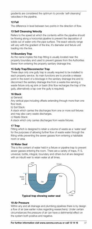
gradients are considered the optimum to provide ‘self-cleansing’ velocities in the pipeline.
12 FallThe difference in level between two points in the direction of flow.
13 Self Cleansing VelocityRefers to the speed at which the contents within the pipeline should be flowing along a horizontal pipeline to prevent the deposition of solids out of water onto the pipe surface. The exact velocity range will vary with the gradient of the line, it’s diameter and fixture unit loading into the line.
14 Boundary TrapAs the name implies this trap fitting is usually located near the property boundary and used to prevent gasses from the Authorities Sewer from entering the property sanitary drainage line.
15 Gully Trap/Disconnector TrapThese days only one gully trap is usually required to be installed to each property service. Its main functions are to provide a release point in the event of a blockage in the sanitary drainage line and to disconnect the sanitary drainage line from a waste line serving a waste fixture only eg sink or basin (this flow recharges the trap of the gully, alternatively a tap over the gully is required).
16 Stacka) General:Any vertical pipe including offsets extending through more than one floor level.b) Soil Stack:A stack which carries the discharges from one or more soil fixtures and may also carry waste discharges.c) Waste Stack:A stack which only carries discharges from waste fixtures.
17 TrapFitting which is designed to retain a volume of waste as a ‘water seal’ for the purposes of allowing further flow of waste water through the fitting while preventing the sewer gasses from entering a habitable room or area.
18 Water SealThis is the content of water held in a fixture or pipeline trap to prevent sewer gasses entering the room. There are a variety of traps, P, S, universal, bottle, integral, boundary and others but all are designed with an inbuilt weir to retain water at all times.
Crown
Weir
Outlet
Dip
Inlet
Waterseal
Typical trap showing water seal
19 Air PressureWithin any and all drainage and plumbing pipelines there is by design a flow of air (see earlier notes regarding researchers). Under certain circumstances the pressure of air can have a detrimental effect on the system both positive and negative.

38 For further information visit www.caroma.com.au or call 13 14 16
20 Induced SiphonageThe loss of water from a trap by siphonage caused by a reduction in pressure at the outlet of the trap. This condition is normally evidenced by flow from fixtures connected to the same pipe but at a higher level.
Induced Siphonage
Higher fixture flushing
Possible solution byintroduction of venton vertical rise
Atmospheric air pressure forces waterseal from the trap
Trap sealloss
Negative pressurecreated in branch linedue to excessive flow from higher fixture
21 Self SiphonageThis is the situation in a branch pipeline to a fixture which by its configuration will cause the pipe to be filled completely and start a syphon effect thereby sucking out the contents of the trap to the fixture. This eliminates the water seal to the trap and can permit sewer gasses/odours to enter the room.
Long leg ofsyphon
Self Syphonage
System SiphonageThe following comments are based upon research carried out by Caroma and other research organisations in the plumbing field. This work suggests that closer attention to detail is required, particularly in regard to the size and number of ventilation pipes on sanitary systems, than has been the practice in the past. Systems are at times being designed and installed to their performance limits and the slightest deviation from the ‘perfect’ condition may lead to a systems failure.As indicated earlier under Background History all systems will at times experience ‘waving’ of the trap seal to a fixture. Provided the seal is not lost entirely thereby allowing sewer gases into the habitable rooms it is a normally occurring feature and does not present a health problem to the occupants. It is important to remember this as time and money can be wasted pursuing this situation unnecessarily.

For further information visit www.caroma.com.au or call 13 14 16 39
Incidences of system siphonage represent a very small percentage of the total number of problems experienced with sanitary plumbing and sanitary drainage systems.
They can and do occur occasionally to floor wastes, basins, sinks and toilet pans both the 11 litre and reduced flushing units. Experience has shown that these problems occur predominantly in newly developed sub-division areas. Almost without exception the problem has been found to be attributed to the problem arising in the system, the individual installation, or the household practices of individual house occupants. Rarely has the fixture been the cause of the complaint.
The following suggestions are provided to help plumbers establish the cause of a system failure in the event of a problem occurring:
a) Has the installation been completed and in particular confirm that all vent lines are connected to the system? The system is prone to malfunctions due to uncompleted works preventing the flow of air and/or water as required for the installation to function correctly. Incorrect grade of line can cause solids to drop out of water flow and progressively build up in the line. When this occurs water will back up and the sudden release can create a negative pressure upstream and thereby ‘suck out’ the traps seal.
b) Does the system comply with the relevant code and regulation? Particular attention should be given to length of branch lines to vent lines, grades and pipe sizes. Remember that the code is the minimum requirements and good safe practice would be to keep all components well within these limitation. In reference to vent lines it should be noted that air flow is subjected to frictional losses just as water is in the water reticulation. Excessive lengths will result in the air relief not reaching pressure spots within the system and vacuums can occur.
c) Ensure that there are no obstructions within the lines which might create partial or intermittent blockages. Blockages will cause excessive pressures to occur and negative pressure close to the trap seal will result in trap seal losses occurring.
d) Confirm that there are no obstructions to the free flow of air through the vent cowl/terminal into the system. Air flow is a critical element in all drainage systems. Any reduction in the source of the air, the vent inlet, will result in a failure to the system and many times this is evidenced by a trap seal loss. Particular notice should be taken of the type of vent cowl installed. Some are manufactured having broad support arms which significantly hinder air flow into the vent line. These will also contribute in a major way to the failure of the system.
e) Check that water in the cistern in the shut off position reaches the designated line of water depth within the cistern. Conservation of water is achieved by employing the smallest quantity of water possible, commensurate with the force needed to ensure waste material is satisfactorily carried through the system. The smallest decrease in these amounts from the source, the cistern, will mean that the volume and pressure of water through the toilet bowl and then the drainage system will be inadequate. Under those circumstances paper and solids will not clear the toilet bowl and/or drainage lines, again causing blockages and malfunctions to occur. Example: Should the water lines be set at 25mm below the designation mark this will result in there being 1 litre less water available for the full flush.
f) Have the Authorities’ mains been checked for any unusual conditions? Overloading, blockages and even the existence of a pumping station located close to the site on the Authorities' sewer mains can be

40 For further information visit www.caroma.com.au or call 13 14 16
contributing factors affecting the correct functioning of house service lines. Pressure from the mains can be exerted into the house lines and excessive fluctuations of water trap seals may eventuate to the extent that the effective seal is lost.
g) Does the installation drain to a septic tank and/or collection chamber? Experience indicates that these systems are less likely to give problems of trap seal loss, where the system has more than one inlet vent pipe. Preferably one vent should be sited towards the high end of the system.In addition water levels within a septic tank or collection chamber should never be permitted to rise above the inlet junction to the tank. This usually occurs in unusual circumstances including a collection chamber which acts as a pump-out well.In the case of a pump-out well, care must be taken to ensure that the chamber weir, junction or pump cut in level are such that the water level remains well below the inlet pipe. Should this not be the case and water backs up the sanitary plumbing line from the chamber a suction within the line could occur through the action of the pump dropping the water level suddenly. This condition is exacerbated in the installations which have single small diameter vent lines connected.Always ensure that correct water levels are set within the chamber, or the provision of additional venting will assist in overcoming the defects of air pressure within the system.
22 Vents
See diagram over page.
a) General: Vent pipes connected to soil and waste pipes to —
i) Minimise or eliminate the negative and positive pressures exerted within pipelines caused by water flow in the pipelines.
ii) Introduce fresh air into the system which to a limited extent reduces the corrosive action of some gasses on metallic pipelines.
iii) To permit foul gasses to be liberated into the atmosphere where they are quickly dispersed by prevailing winds.
b) Branch: A graded vent at any one floor level interconnecting two or more individual trap vents or group vents.
c) Cross: A vent interconnecting a stack and its relief vent.
d) Ground/Induct: A vent in house drainage which is directly connected to a boundary trap riser and which terminates close to ground surface level. Also called low level vent or induct vent.
e) Relief: A vent installed in a stack below the lowest fixture.
f) Stack: The extension of a discharge stack above the highest connected discharge pipe.
g) Trap: A vent pipe venting an individual trap to the open air or to a main or branch vent pipe for the prevention of loss of water-seal in the trap.
h) Cowl: A sanitary fitting for installation on the outlet end of a vent pipe to prevent the ingress of birds, rodents and foreign matter.

For further information visit www.caroma.com.au or call 13 14 16 41
Soil stack
Above ground
(sanitary plumbing)
Overflow gulleyBelow ground (sanitary d
rainage)Boundary trap
Groupvent
TrapsVent pipe toterminate abovelow level roof.
SewerInduct vent
Branch vent
Group vent branching fromcommon discharge pipe
Stack vent
Cowl (wire basket)
Sketch indicating sanitary drainage, sanitary plumbing, stack, branches, vents and boundary trap, and overflow gully.
23 JunctionThis is a fitting used in a sanitary plumbing system to connect a branch pipe or channel.
24 Wash Down Pan
Wat
er S
eal
App
rox.
50m
m InletHorn
S-trap
P-trap
Connection endto pan connector
Foot Sump
Pan Rim
Pan Foot Level
The WC pan employed almost universally in Australia is known as a ‘wash down’ pattern. It depends entirely upon the efficient use of free falling water into the pan, around the rim to completely clean the bowl, force the contents of the trap over the weir into the connected soil pipe and to re-charge the trap. In addition the wash down pan previously required 11 litres of water to operate. Caroma Smartflush technology, modern design and production methods have resulted in a dramatic reduction in the amount of water used to approximately 4.5 litres for full flush and 3 litres for half flush.
25 Pan ConnectorA pipe fitting which has a suitable sized socket at one end to connect to the outlet of a WC pan. This is normally by means of a neoprene rubber ring. The other end of the Connector joins onto the soil branch line or drainage line.
26 CisternA receptacle constructed to hold water until activated by a lever/button/electronic control to permit water to flow into the attached fixture/pipe work. The inlet valve is designed to automatically refill and is designed to maintain an air gap for health reasons.

42 For further information visit www.caroma.com.au or call 13 14 16
27 FlushvalveSometimes referred to as flusherette valve and is now available incorporating two alternative principals.i) Standard Valve connected by pipe work to a storage tank located elsewhere in the project and at a higher level. This tank incorporates the required air gap and only flush valves are permitted to connect to the pipe work from this tank.ii) Caroma Schell Flusherette Valve. This device incorporates a unique and air break system. This prevents back siphonage of water into the Authorities' mains and therefore can be connected direct to the potable water supply of the building (confirmation of this should be made with the local authority prior to commencement of installation). Detailed attention to the sizing of the pipeline to the valve is essential in order to provide a satisfactory installation.
28 Air Gap The Australian practice has been to rigidly adhere to the use of a physical air gap to prevent the contents of a tank, cistern, reservoir or fixture from re-entering the water system by virtue of siphoning the contents into the potable water system.Attitudes towards the alternative, Mechanical Backflow Prevention Devices, (see below) previously considered to be not an acceptable method of control are changing and these devices are used in certain cases. (see Caroma Schell flusherette valves above).
29 Mechanical Backflow Prevention DevicesThere are several classifications of these valves some permitting the valve to operate by inducing air into the system to prevent siphonage taking place, to double check valves and hose connection vacuum breakers.All are stated to be designed to prevent the reverse flow of water from a potentially polluted source into a potable water supply system.
30 Extended Push Button Schell InductWC FlushvalveExtendedPush Button
Concealed cisterns and flushvalves mounted within walls or ducts cannot be operated satisfactorily with the normal push-button. Extended push button with associated longer rods, sleeves and wall buttons can be fitted and adjusted to various lengths.
31 Isolating ValveAs the name implies it is a valve to separate or isolate one part of the water system from the rest of the reticulation. Can also be referred to as a Stop Valve though technically a Stop Valve may be a valve on the main pipeline and its use is to stop the flow of water through that section of pipe.
32 UnionsJoints which are easily undone and are always installed adjacent to fixtures to facilitate their removal.
33 Access PanelsThese are removable panels fitted to plumbing ducts to facilitate the inspection/maintenance of the plumbing services. They should be large to ensure that all sections of the pipe work are easily accessible for maintenance/repairs.
34 Water Pressurea) General:Is the force created in a reticulated water supply by either gravity or pressurisation by the use of pumps.
For further information visit www.caroma.com.au or call 13 14 16 43
b) Static Pressure:
Is the force exerted in a pipeline when there is a ‘no flow’ condition.
c) Flow Pressure:
Is the residual force exerted in a pipeline when the water within the line is flowing. The flow pressure will always be less than the static pressure of the same pipeline.
35 Water Hammer
This is the audible result of the force exerted in a pipeline when the flow of water is suddenly stopped. Dishwashers and washing machines which have solenoid valves incorporated are prime causes of ‘water hammer’. Loose or poorly installed pipe work will exacerbate the noise problem. In certain cases the installation of a ‘Water Hammer Arrestor Valve’ will be required to eliminate the sound problem.
36 Pipe work
a) Sanitary Plumbing:
i) Cast Iron—
Commonly used in high rise buildings and other commercial/industrial application. Very good material with high acoustic qualities
ii) Copper —
Usually installed in branch line positions from cast iron stacks. Very good material of long life suitable allowances for expansion are essential.
iii) U.P.V.C. —
Poly vinyl chloride is employed extensively in domestic and other low rise residential projects. Very good material recognition of fire codes, expansion and solvents limitation necessary for satisfactory installation.
iv) Stainless Steel —
Rubber ring push in joints for ease of installation. A variety of rings are available for unusual or aggressive flow situations. Can be employed in numerous situations on stack and branch line applications
b) Sanitary Drainage
i) Cast Iron —
Used mainly in commercial/industrial application where made up ground is encountered.
ii) U.P.V.C. — Used extensively in residential light commercial installations. Should not be used in any situation taking extremely high temperatures or where discharges may include solvents.
iii) Vitrified Clay — A very well proven material suitable for almost all applications of commercial/industrial/trade waste and residential applications.
iv) Stainless Steel — Can be used extensively in buildings and underground. Correct bedding required. Slightly different diameters readily adapted to all other materials by availability of fittings.
37 Metric Conversion
Pipe diameters used in the Australian construction industry are the result of a ‘soft conversion’ from imperial to metric standard. eg the pipe diameter is rounded off and hence –
3 inches = 76.20mm is known as 75mm diameter.
4 inches = 101.60mm is known as 100mm diameter.

44 For further information visit www.caroma.com.au or call 13 14 16
38 Pipe SizingJoint Australia – New Zealand Standards
While the use of 80mm diameter pipeline in residential soil line is permitted, the usual practice in Australia is to use 100mm diameter pipes.
In New Zealand however, the use of 80mm diameter pipelines is standard practice over several years. It should be noted that in previous years New Zealand venting to the system has been more stringent than in Australian installations.
New Zealand is one of a minority or countries which connect a 100mm pan outlet to 80mm waste pipe as standard. New Zealand installers should therefore consider the original New Zealand specifications for venting being the most appropriate when using 80mm waste pipe rather than AS3500 which is primarily based on 100mm waste pipe systems.
New Zealand plumbers should also note that all plumbing work should be carried out in accordance with either Australian practice or the New Zealand plumbing code. An installation incorporating a combination of the requirements from either system is not recommended.
It has long been recognised that satisfactory sanitary drainage, systems are dependent to a significant degree to adequate ventilation being present.
For some time, as the systems are further refined to recognise economic restraints, overseas and local research and experience highlights that extra care in installations is essential to cope with these refinements and restraints.
The reduction in venting, permitted under the joint standard, normally results in a safe and adequate installation which incorporates 100mm diameter lines. It should be noted however that codes and standards are always minimum requirements only, set down as guidelines for the industry. Unusual, or detrimental, installation conditions may require increased numbers of, or larger diameter, vent lines to counter any adverse effects in order to maintain the integrity of the system. This would become a critical consideration if the reduced venting was combined with the use of 80mm diameter lines.
Conditions which can adversely affect the installation may appear to be minor but their collective effects will be adversely significant.
This is particularly so in the case of 80mm diameter lines as the system will be more sensitive than 100mm diameter lines to any installation defects. These may appear to be minor but their collective effects will be adversely significant.
Apart from the need to ensure lines are clear of any material which could cause blockages, examples of these include such items as correct grade, loadings, true bore and straightness of invert, position of vent termination point, distance of vent termination point to fixtures and the effects of unusual roof structures or nearby features which affect the action of wind across the termination point of the vent.
Incorrect application of one or more of these features may lead to a failure of the system. Should this occur in a situation of reduced or inadequate venting of the line expensive rectification work may eventuate.
39 General
The above information is given as an advisory capacity only. Reference must be made to AS/NZS 3500.2.2 and associated information issued by the various statutory authorities for application to specific installations.