Implementation of a UDP/IP Stack on HCS12...
24
© Motorola, Inc., 2002 AN2304/D 10/2002 Implementation of a UDP/IP (User Datagram Protocol/Internet Protocol) Stack on HCS12 Microcontrollers Application Note By: Gerald Kupris, Freescale, Munich Harald Kreidl, Freescale, Munich Norbert Gutknecht, Metrowerks, Munich Dirk Lill, University of Cooperative Education, Lörrach Nathan Braun, University of Cooperative Education, Lörrach Connecting Embedded Applications to the Internet Where the Internet may have been a dedicated network for computer data exchange in it's infant years, today more and more small (non-PC based) intelligent "machines" are connected to the Network of Networks. The prediction is that by 2005, the amount of non-PC users on the Internet will far exceed the amount of PC's! Today, a highly integrated microcontroller can handle the functional control of these machines. To connect the microcontroller to the Internet, one must implement a protocol stack on the device. To function, this protocol usually requires a powerful processor, a complete operating system, and a large amount of memory. In this case, the implementation of a stand-alone Internet protocol stack could be a solution. In order to design an embedded system, one must design both the hardware around a microcontroller and the software. Depending on the target hardware as well as the complexity of the problem, the developer has to decide whether to use an operating system. According to market analysis, more than 75% of the embedded applications use a proprietary or free operating system, about 25% do not use an operating system. Big operating systems usually have Internet protocols already built-in, whereas deeply embedded systems do not yet provide a TCP/IP (Transmission Control Protocol/Internet Protocol) stack. However, a 8- or 16-bit microcontroller may not have enough resources for the implementation of an operating system. Software implementations without operating systems can be found in less complex applications often using small microcontrollers with strict hardware and runtime restrictions. The choice of writing standalone code is often made because of the need to optimize memory usage, code size, and run-time behavior. Since the writing of this standalone code is target specific, it is often not portable to other targets. Freescale Semiconductor, I For More Information On This Product, Go to: www.freescale.com nc...
Transcript of Implementation of a UDP/IP Stack on HCS12...
AN2304/D10/2002
Implementationof a UDP/IP (User DatagramProtocol/Internet Protocol) Stack on HCS12 Microcontrollers
Application Note
F
ree
sca
le S
em
ico
nd
uc
tor,
I
nc
...
By: Gerald Kupris, Freescale, MunichHarald Kreidl, Freescale, MunichNorbert Gutknecht, Metrowerks, MunichDirk Lill, University of Cooperative Education, LörrachNathan Braun, University of Cooperative Education, Lörrach
Connecting Embedded Applications to the Internet
Where the Internet may have been a dedicated network for computer data exchange in it's infant years, today more and more small (non-PC based) intelligent "machines" are connected to the Network of Networks. The prediction is that by 2005, the amount of non-PC users on the Internet will far exceed the amount of PC's!
Today, a highly integrated microcontroller can handle the functional control of these machines. To connect the microcontroller to the Internet, one must implement a protocol stack on the device. To function, this protocol usually requires a powerful processor, a complete operating system, and a large amount of memory. In this case, the implementation of a stand-alone Internet protocol stack could be a solution.
In order to design an embedded system, one must design both the hardware around a microcontroller and the software. Depending on the target hardware as well as the complexity of the problem, the developer has to decide whether to use an operating system. According to market analysis, more than 75% of the embedded applications use a proprietary or free operating system, about 25% do not use an operating system. Big operating systems usually have Internet protocols already built-in, whereas deeply embedded systems do not yet provide a TCP/IP (Transmission Control Protocol/Internet Protocol) stack.
However, a 8- or 16-bit microcontroller may not have enough resources for the implementation of an operating system. Software implementations without operating systems can be found in less complex applications often using small microcontrollers with strict hardware and runtime restrictions. The choice of writing standalone code is often made because of the need to optimize memory usage, code size, and run-time behavior. Since the writing of this standalone code is target specific, it is often not portable to other targets.
© Motorola, Inc., 2002
For More Information On This Product, Go to: www.freescale.com
rxzb30
ForwardLine
rxzb30
freescalecolorjpeg
rxzb30
fslcopyrightline

AN2304/D
F
ree
sca
le S
em
ico
nd
uc
tor,
I
Freescale Semiconductor, Inc.n
c..
.
Therefore, the described system solution favors a different way forward where the Internet protocol stack is implemented as a stand-alone stack. But, this stack is modular, portable, and can also be used together with a scalable embedded operating system (e.g., Metrowerks®(1) OSEKturbo OS). The stack was implemented on a Freescale HCS12 derivative (MC9S12DP256), a low-cost but highly integrated 16-bit microcontroller.
Internet Protocol Standards: The OSI/ISO Communication Model
The Internet is a collection of individual networks, connected by intermediate networking devices, that function as a single large network. The challenge when connecting various systems is to support communication between disparate technologies. For example, different sites may use different types of media, or they might operate at varying speeds. Network management must provide centralized support and troubleshooting capabilities. Configuration, security, performance, and other issues must be adequately addressed for the inter-network to function smoothly.
The OSI (Open Systems Interconnect) reference model which was introduced in the seventies and released in 1984 describes how information from a software application in one node moves through a network medium to a software application in another node (see Figure 1). The OSI reference model is a conceptual model composed of seven layers, each specifying particular network functions. It is now considered the primary architectural model for inter-device communications.
Figure 1. The OSI/ISO Communication Layer Model
1. Metrowerks is a registered trademark of Metrowerks, Inc., a wholly owned subsidiary of Freescale Semiconductor, Inc.
LAYER 7: APPLICATION LAYER
LAYER 6: PRESENTATION LAYER
LAYER 5: SESSION LAYER
LAYER 4: TRANSPORT LAYER
LAYER 3: NETWORK LAYER
LAYER 2: DATA LINK LAYER
LAYER 1: PHYSICAL LAYER
DNS
TCP
IP
ARP
ETHERNET IEEE 802.3
SMTP HTTP
PPP
WIRELESS
FTP
SLIP
WAP
UDP
HDLC /SDLC
SERIAL COMMUNICATION
SOCKETSAPI
OSI/ISO COMMUNICATIONLAYER MODEL EMAIL WEB BROWSER MOBILE PHONE
2 Implementation of a UDP/IP Stack on HCS12 Microcontrollers
For More Information On This Product, Go to: www.freescale.com

AN2304/DInternet Protocol Standards: The OSI/ISO Communication Model
F
ree
sca
le S
em
ico
nd
uc
tor,
I
Freescale Semiconductor, Inc.n
c..
.
The OSI model provides a conceptual framework for communications between computers, but the model itself is not a method of communication. Actual communication is made possible by using communication protocols. The protocol is a formal set of rules and conventions that governs how nodes exchange information over a network medium. The known Internet communication protocols do not fully correspond to the OSI model, although they are very similar to this model. Protocols used in the Internet are:
• Transfer Control Protocol (TCP)
• User Datagram Protocol (UDP)
• Serial communications support SLIP (Serial Line Internet Protocol)
The set of programs used for Internet communication is usually refered to as the “Internet Protocol Stack” or sometimes “TCP/IP Stack”.
TCP/IP was already established while the ISO networking standards were evolving. Nevertheless, TCP/IP protocol can be described with the ISO/OSI model. The principle behind layering is each layer hides its implementation details from the layer below and the layer above. Each layer on the transmitting node has a logical peer-to-peer connection with the corresponding layer in the receiving node. This is accomplished through the use of encapsulation.
Figure 1 shows the TCP/IP stack in terms of the OSI layers. In this illustration, the stack is shown in a typical LAN (Local Area Network) application. For WAN (Wide Area Network) or point-to-point applications the lower layers can be somewhat more complicated. Each layer in a receiving machine gets received frames from the layer below and transmits sending frames to the layer above. Similarly each layer in a sending node gets received frames from the layer above and transmits its frames to the layer below.
Layer 1: The Physical Layer
The physical layer describes the actual physical transmitting medium (i.e., radio, fiber-optic cable, coaxial conductor, cable twisted). The physical layer exhibits the following substantial characteristics:
• Data are treated as being bit streams, whereby no distinction between "data" is made in the actual sense and control information (e.g., control of character).
• Standardization concerns information exchange as well as the representation of concrete signals and physical dimensions. Apart from electrical parameters, mechanical and/or constructional parameters can be standardized (e.g., plugs, cables, ect.).
• Signals are designated and defined physically, whereby the meaning and the co-operation of these signals are described.
Implementation of a UDP/IP Stack on HCS12 Microcontrollers 3
For More Information On This Product, Go to: www.freescale.com

AN2304/D
F
ree
sca
le S
em
ico
nd
uc
tor,
I
Freescale Semiconductor, Inc.n
c..
.
Important aspects of this layer are the timing of the signals as well as the permissible tolerances. The physical layer makes connection possible to:
• Existing physical connections (or connections which can be created) like V.24 (RS232) and X.21 for industrial automation systems
• Ethernet (CSMA/CD)
• Token Ring for LAN applications
The services provided by the physical layer to the data link layer can be divided according to different criteria. The supported modes of operation are simplex, half duplex, and full duplex, whereby synchronous and asynchronous transmission is possible.
The physical layer uses these three services:
• Initialization of the interface as well as definition of the data communication direction
• Transport of the individual bits respectively (bit stream)
• Dismantling of the physical connection
NOTE: The physical layer implementation is always specific to the type of transmission.
Layer 2: The Data Link Layer
The central task of the data link layer is handling data communication supply to/from secured channels. In contrast to the physical layer, the data link layer understands the data more as a structured message, in particular the transmission of a single character. Services which the data link layer makes available to the network layer provide control of the information flow during the connection between two nodes.
Error recognition and, if necessary, error correction accomplished in the data link layer refers only to framing errors. However, the data link layer is not able to determine errors concerning content or meaning of the data. For this reason, only an examination takes place to determine if data sent by the transmitter are identical to data received by the receiver. If necessary, the split of a connection into several transmission paths also takes place within the data link layer.
PPP has to be implemented according to [RFC1661] with its subprotocols:
• LCP (Link Control Protocol)
• PAP (Password Authentication Protocol)
• IPCP (Internet Protocol Control Protocol)
For future use the possibility of implementing the CHAP (Challengege Handshake Authentication Protocol) should be provided as well as DHCP (Dynamic Host Configuration Protocol).
4 Implementation of a UDP/IP Stack on HCS12 Microcontrollers
For More Information On This Product, Go to: www.freescale.com

AN2304/DInternet Protocol Standards: The OSI/ISO Communication Model
F
ree
sca
le S
em
ico
nd
uc
tor,
I
Freescale Semiconductor, Inc.n
c..
.
The Link Control Protocol accomplishes:
• Establishment of the used package size
• Authorization and monitoring of the transmission quality
Layer 3: The Network Layer
The tasks of the network layer include identification of the transmission path. This means the identification of the most favorable way from node A to node B, assuming that several ways are possible. A further task of the network layer is flow control (i.e., the control of the package flow by the network).
Additional tasks are:
• Signalling non-correctable errors to the higher layers
• Resetting a connection in the case of an error
• Multiplexing several connections
• Assigning data to certain services
NOTE: The IP (Internet Protocol) belongs to the network layer and includes the IP addressing scheme.
The implementation of the IP is according to Version 4 (IPV4) described in [4]. To preserve performance and memory of the system it does not have to allow fragmentation. Checking the header checksum on incoming IP datagrams is an option that can be switched off.
ICMP communicates error and administrative messages between IP systems and is an integral part of the IP. It has to be implemented according to [5]. Most of the 30 messages and queries are used to indicate routing and gateway problems. Therefore, an ICMP implementation for an embedded device can be limited to one message type that is an echo reply. An echo reply is a message sent upon echo request. An echo request can be sent to an embedded device using the program ping <ip address>. An ICMP echo request can be used to diagnose the communication link between a computer and the embedded device on IP level.
Layer 4: The Transport Layer
The task of the transport layer consists of:
• Structure
• Administration
• Dismantling of logical connections
During the transmission procedure, the transport layer must receive data from the next higher layer and pass on the packages to the network layer. Therefore, the data must be segmented into corresponding packages. This procedure is called message segmentation. Within the transport layer error handling is accomplished.
Implementation of a UDP/IP Stack on HCS12 Microcontrollers 5
For More Information On This Product, Go to: www.freescale.com

AN2304/D
F
ree
sca
le S
em
ico
nd
uc
tor,
I
Freescale Semiconductor, Inc.n
c..
.
On the transport layer there are only two possibilities for data connections, a reliable data connection (TCP) and an unreliable data connection (UDP). On this level there are no extensions in the forseeable future. In contrast, the IP protocol (situated on the network layer in the OSI reference model) might be extended to the possibility to process Internet Protocol Version 4 (IPv6) datagrams. Moreover, there is a specification to encrypt IP datagrams known as IPsec [6].
For the transport layer, the two most common protocols which have to be implemented in the Internet protocol stack are:
• TCP (Transport Control Protocol)
• UDP (User Datagram Protocol)
Transport Control Protocol (TCP)
TCP is the most common protocol providing a reliable data connection between two network partners. It is used for HTTP (HyperText Transfer Protocol), SMTP (Simple Mail Transport Protocol), FTP (File Transfer Protocol), and other services. TCP serves as a foundation for such applications as embedded web server and email client providing a secure data connection between two network partners. Implementation of a TCP protocol is rather complex and is not always required in an embedded application.
User Datagram Protocol (UDP)
UDP is a much simpler protocol but it is not as widely used in traditional internet services. For example, standard applications which use UDP are:
• TFTP (Trivial File Transfer Protocol, Port 69)
• DNS Name Server (Domain Name System, Port 53)
• RPC (Remote Procedure Call, Port 111)
• SNMP (Simple Network Management Protocol, Port 161)
• LDAP (Lightweight Directory Access Protocol)
In embedded applications, UDP is most likely to be used as a proprietary network connection. For example, the transfer of small data pieces such as results of measurements, remote controls, or some user data. See Figure 2.
Layer 5: The Session Layer
The session layer supports different user application dialogues. Since TCP/IP only incorporates protocols through the transport layer, all the software above the transport layer is generally lumped together as networking applications. For this reason, often the session layer is not differentiable from the application layer.
NOTE: The Berkley BSD ‘Sockets’ Application Programming Interface (API) is a commonly used session/presentation layer.
6 Implementation of a UDP/IP Stack on HCS12 Microcontrollers
For More Information On This Product, Go to: www.freescale.com

AN2304/DInternet Protocol Standards: The OSI/ISO Communication Model
F
ree
sca
le S
em
ico
nd
uc
tor,
I
Freescale Semiconductor, Inc.n
c..
.
Figure 2. Use of UDP in an Embedded Application
Layer 6: The Presentation Layer
As is the case with the application layer, the user application stands in the center of the presentation layer. Some services of the presentation layer are:
• Data compression
• Data encryption
NOTE: The presentation layer has no specific role in TCP/IP because TCP/IP is only implemented from the data link layer through the network layers. Therefore, any presentation level functionality is often viewed as part of the application layer.
Layer 7: The Application Layer
The application layer is accessible for the user and describes superordinate applications. Their function relies on the functions of the underlying layers. The application layer encompasses virtual all applications of TCP/IP networking including network file systems, web server or browser, and client server transaction protocols.
Typical Internet applications are:
• FTP (File Transfer Protocol)
• SMTP (Simple Mail Transport Protocol)
• HTTP (HyperText Transfer Protocol)
Also, object exchange methods such as DCOM (Distributed Common Object Model) and CORBA (Common Object Request Broker Architecture) are considered part of the application layer. Refer to Figure 3.
MODEM
EMBEDDED APPLICATION WITHTEMPERATURE SENSOR CALLSTHE ISP ON A REGULAR BASIS
AND TRANSMITS DATA VIA UDP/IP
TELEPHONELINE
INTERNET
DIAL-UP SERVERAT INTERNET SERVICE
PROVIDER (ISP)
PC WITH UDP/IP CLIENTAND A PROPRIETARY APPLICATIONTO DISPLAY THE MEASURED DATA
Implementation of a UDP/IP Stack on HCS12 Microcontrollers 7
For More Information On This Product, Go to: www.freescale.com

AN2304/D
F
ree
sca
le S
em
ico
nd
uc
tor,
I
Freescale Semiconductor, Inc.n
c..
.
Figure 3. Transmission of HTTP Information via a Serial Link
As shown in Figure 3, an important fact of Internet communication is that information does not travel in a continous stream, but in the form of small data packets. A packet is an information unit whose source and destination are network-layer entities. A packet is composed of the network-layer header and possibly a trailer and upper-layer data. The header and trailer contain control information intended for the network-layer entity in the destination system. Data from upper-layer entities is encapsulated in the network-layer and trailer. The advantage of this packet technology is that every packet travels independently from the others making the whole information transfer resistant against transmission failures.
A disadvantage of the packet technology is that every protocol layer adds some information to the data packet. Therefore, it is not very efficient to submit just a small piece of information because the overhead generated by the various protocols can be much larger than the transmitted data itself (refer to Figure 3).
The next important fact of Internet communication is that every single device in the network has its own unique address, called the IP address. In the current specification the IP address uses four 8-bit numbers. This 32-bit address space looks like xxx.xxx.xxx.xxx in decimal enumeration. In the early 90s, the first address shortage crisis hit the Internet technical community. The present solution will sustain the Internet for a few more years by making more efficient use of the existing 32-bit address space (Internet protocol V4). For a more lasting solution, the implementation of the Internet protocol V6 and its 64-bit address space is necessary.
SOCKETSAPI
TCP UDP
WAP FTP DNS SMTP HTTP
IP
ARP SLIP HDLCIPCP
LCP
ETHERNET SERIAL COMMUNICATION3 BYTEn BYTE8 BYTE20 BYTE9 BYTE DATA
UDP/IPFRAME
HEADER TRAILER
USER APPLICATIONS
PPP
8 Implementation of a UDP/IP Stack on HCS12 Microcontrollers
For More Information On This Product, Go to: www.freescale.com

AN2304/DUse of UDP in Embedded Applications
F
ree
sca
le S
em
ico
nd
uc
tor,
I
Freescale Semiconductor, Inc.n
c..
.
Use of UDP in Embedded Applications
The User Datagram Protocol (UDP) can be used in embedded applications. Some advantages of the UDP are:
• Small code and memory size
• Small overhead
• Easy to implement
• Fast processing of the packet since no acknowledgement is required
Software Interfaces
The implementation of the four protocols, TCP, UDP, IP, and ICMP form a package of software that comprises both the transport layer and the network layer in the OSI reference model and is defined by two interfaces, one to the application layer and one to the data link layer. See Figure 4.
Figure 4. Main Software Interfaces
Figure 4 shows the two main software interfaces that have to be implemented and described compared to the OSI reference model.
1. Interface A defines the data exchange between the transport and session layer in the OSI reference model. There exists a de facto standard for this interface, the Berkeley Socket API (‘sockets’). Most of the implementations of TCP/IP stacks use a similar API; therefore, for compatibility purpose as well as ease of use it is important to provide an API that is similar to the sockets API. Since the sockets API is a widely used standard it guarantees the implementation of all current application level protocols.
2. Interface B interfaces the data link layer and the network layer in the OSI reference model. On this interface the lower layers, data link, physical, and media provide IP packets. This interface has to permit a
APPLICATIONPRESENTATION
SESSION
TRANSPORT
NETWORK
DATALINKPHYSICAL
MEDIA
TCP/IP STACK
NETWORK
OSI REFERENCE MODEL
INTERFACE A
INTERFACE B
TCP UDP
IP ICMP
HTT
P
SMTP
FTP
POP
DN
S
SER
IAL
LIN
E
lrDA
WLA
N
EHTE
RN
ETIE
EE 8
02.2
INTERFACE
Implementation of a UDP/IP Stack on HCS12 Microcontrollers 9
For More Information On This Product, Go to: www.freescale.com

AN2304/D
F
ree
sca
le S
em
ico
nd
uc
tor,
I
Freescale Semiconductor, Inc.n
c..
.
simultaneous use of multiple network interfaces. Moreover, it has to be designed independent of the hardware used as the physical link.
The design of interface B does not have to fulfill any convention. However, it is important that the design allows use of the UDP/IP or TCP/IP stack with different network interfaces.
Software Structure and Description of the UDP/IP Stack on the HCS12
The implementation of the UDP/IP stack on a HCS12 microcontroller is based on the work of Rene Trenado [15] and Steven Torres [17]. In difference to the original solution, several changes were introduced:
• The hardware independence was improved to make the code more portable to other Freescale architectures. In the current work the code was ported to a HCS12 derivative.
• The structure of the program modules was modified to improve the layering (see Figure 5).
• The modularity of the software was improved.
• It is possible to add other network interfaces (for example, Ethernet)
• Documented APIs are used for the communication between the software layers. The higher layers communicate to the lower layers via these APIs. The lower layers use a callback function to notify the higher layer about the presence of an event.
Figure 5. UDP/IP Server Software Layers
APPLICATIONLAYER
TRANSPORTLAYER
NETWORKINTERFACE
NETWORKINTERFACE
LAYER
main.c
timeout.c
debug.c
UDPIP.c
PPP.c
physical.c
drv_modem.c
drv_SCI.c
APPLICATION
UDP/IP– UDP– IP– ICMP
PPP
PHY INTERFACE HANDLER
MODEM
SCI
HARDWARE
10 Implementation of a UDP/IP Stack on HCS12 Microcontrollers
For More Information On This Product, Go to: www.freescale.com

AN2304/DSoftware Structure and Description of the UDP/IP Stack on the HCS12
F
ree
sca
le S
em
ico
nd
uc
tor,
I
Freescale Semiconductor, Inc.n
c..
.
The project itself was created using the Metrowerks CodeWarrior®(1) IDE. A folder structure has been created, so each Internet communication layer corresponds to an appropriate folder (see Figure 6).
Figure 6. UDP/IP Server File Structure
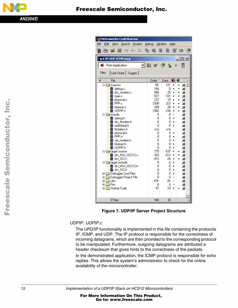
The CodeWarrior Project “4 IP UDP ICMP.mcp” is located in the directory “4 IP UDP ICMP”. The Project itself involves several source and header files (see Figure 7). A description of the software modules follows.
Application: main.c
This application consists of checking the pins of a digital input port (here port A), which might be connected to application specific hardware (e.g., sensors). When the port pin state changes, a UDP datagram is sent to a predefined communication port. This datagram contains the port’s state. If the peer is connected to the correct communication port (here 1080), the current state is shown by the ‘Peer A’ application
1. Code Warrior is a registered trademark of Metrowerks, Inc., a wholly owned subsidiary of Freescale Semiconductor, Inc.
Implementation of a UDP/IP Stack on HCS12 Microcontrollers 11
For More Information On This Product, Go to: www.freescale.com
AN2304/D
F
ree
sca
le S
em
ico
nd
uc
tor,
I
Freescale Semiconductor, Inc.n
c..
.
Figure 7. UDP/IP Server Project Structure
UDPIP: UDPIP.c
The UPD/IP functionality is implemented in this file containing the protocols IP, ICMP, and UDP. The IP protocol is responsible for the correctness of incoming datagrams, which are then provided to the corresponding protocol to be manipulated. Furthermore, outgoing datagrams are attributed a header checksum that gives hints to the correctness of the packets.
In the demonstrated application, the ICMP protocol is responsible for echo replies. This allows the system’s administrator to check for the online availability of the microcontroller.
12 Implementation of a UDP/IP Stack on HCS12 Microcontrollers
For More Information On This Product, Go to: www.freescale.com

AN2304/DSoftware Structure and Description of the UDP/IP Stack on the HCS12
F
ree
sca
le S
em
ico
nd
uc
tor,
I
Freescale Semiconductor, Inc.n
c..
.
PPP: PPP.c
The PPP file contains the functions for datagram encapsulation and link establishment to the Internet service provider or a dial-up computer. Up to this layer the data stream is interrupt driven by incoming bytes on the serial interface. From PPP on, this stream is divided into packets containing datagrams or PPP information.
PHYSICAL: physical.c
This file controls the lowest layer protocols which allow for different hardware configurations to be combined with the PPP module. For example, a modem, a null modem cable, or different interface standards (like RS232) may be utilized for the connection to the host computer. Furthermore, a state machine is implemented which gives the PPP layer information about its lower layer status.
MODEM: drv_modem.cThe modem driver file is responsible for the correct communication between the protocol stack and the modem. On the modem’s side, command strings are sent establishing the modem’s parameters. The answer strings sent by the modem are interpreted and handled in interrupt service routines, so that the modem does not block the microcontroller’s runtime. The dedicated AT command set is to be modified in the file set_modem.h.
SCI: drv_SCI.cThe SCI file contains drivers for interrupt supported sending and receiving over the SCI interface. Here, the specified SCI is enabled or disabled. The parameters of the SCI interfaces are specified in the header file drv_SCI.h.
TIMER: timeout.cThe timer module contains blocking and non-blocking routines for generating timeouts. The time to wait is given in 10 millisecond steps. The blocking timeouts (Tot_Delay(xx)) are for short waiting periods and for debugging purposes (i.e., when the programmer does want the program to halt its current execution).
DEBUGGING: debug.cThe debugging module provides functions that present information concerning the protocol state on a second serial interface. The information may be viewed on a terminal program like HyperTerminal®(1) or Tera Term™(2). Refer to Figure 8.
1. HyperTerminal is a registered trademark of Hilgraeve, Incorporated.2. TeraTerm is freeware, for additional information refer to the program home page at
<http://hp.vector.co.jp/authors/VA002416/teraterm.html>
Implementation of a UDP/IP Stack on HCS12 Microcontrollers 13
For More Information On This Product, Go to: www.freescale.com

AN2304/D
F
ree
sca
le S
em
ico
nd
uc
tor,
I
Freescale Semiconductor, Inc.n
c..
.
Figure 8. Debug Information Received from the MC9S12DP256 SCI1
The UDP/IP stack has to be designed to react on events. Since the communication is based on a layer model in which every layer has specified functionality, it is important that the layers communicate with each other over defined functions. Incoming data arrival events notify higher layer with the use of callback functions whereas outgoing data is passed from higher layers to lower layers using interface functions. Normally, there is no data copied but pointers are passed as function arguments. When no communication is occurring, event driven communication reduces CPU activity.
The UDP/IP stack was programmed in a non-blocking manner. Managing time-outs and waiting for certain conditions are implemented by the use of two state machines: one for the initialization and management of the modem and one for the Point-to-Point Protocol (PPP). The structure of the modem state machine is explained in Figure 9.
14 Implementation of a UDP/IP Stack on HCS12 Microcontrollers
For More Information On This Product, Go to: www.freescale.com

AN2304/DSoftware Structure and Description of the UDP/IP Stack on the HCS12
F
ree
sca
le S
em
ico
nd
uc
tor,
I
Freescale Semiconductor, Inc.n
c..
.
Figure 9. State Machine Structure for Modem Initializationand Management
The error codes of the modem are:
• Busy: E_MOD_BUSY
• No Answer: E_MOD_NOANSW
• Carrier Loss: E_MOD_NOCARR
These codes may be treated inside the application or illustrated on a display.
The structure for the state machine for the PPP is explained in Figure 10.
Figure 10. State Machine Structure for Point-to-Point Protocol (PPP)
MOD_NO_INIT
MOD_DATA
MOD_CONNECTING MOD_DIALING
MOD_COMMAND
MOD_OFF_HOOK
SYSTEM ERROR INITIALIZING COMMANDS
CARRIER DETECT BUSY, NO ANSWER GO OFF-HOOK COMMANDS
ESCAPE SEQUENCE,CARRIER LOSS,
DTR FALLING EDGE
OK DIALISP
FAIL ESTABLISH
CLOSING
AUTHENTICATEFAIL
DOWN
OPENED
SUCCESS/NO PASSWORD
UP, HEREMODEM CD
NETWORK
NO NETWORK
DEAD
NETWORK
TERMINATE
CARRIERLOST
Implementation of a UDP/IP Stack on HCS12 Microcontrollers 15
For More Information On This Product, Go to: www.freescale.com

AN2304/D
F
ree
sca
le S
em
ico
nd
uc
tor,
I
Freescale Semiconductor, Inc.n
c..
.
In RFC 1661, the PPP state machine is described in a complete manner. In the presented solution, there are two main states, which are stored in a status variable. In cases where the NETWORK state is not reached, the LCP handling routine answers depending on the incoming packets and leaves the management of the state machine to the other peer.
If possible, the API functions are limited to Init, Open and Close, Read and Write (see Table 1). These limitations allow an easier implementation of further protocol files. The return codes of these functions are interpreted in the calling functions.
Table 1. UDP/IP Stack Application Programming Interfaces
ReturnValue
FunctionName
Parameters Description(1)
SBYTE UDPIP_Initvoid (*pCallback) BYTE *cInData
• Initialize UDP and IP layer• Call PPP_Init
SBYTE UDPIP_Open None• Call defined interfaces’ open function
(here PPP_Open)
SBYTE UDPIP_Close None• Call defined interfaces’ close function
(here PPP_Close)
SBYTE UDPIP_WriteWORD uiSourcePort BYTE *cOutDataWORD uiDataLen
• Store data to be sent• Invoke datagram building• Call PPP send function
SBYTE PPP_Initvoid (*CallbackIP)(BYTE) BYTE *cIPAddr
• Initialize PPP• Call Phy_Init
SBYTE PPP_Open None• Check Phy_Open• Open PPP
void PPP_Close None• Close Phy-layer• Close PPP
void PPP_WriteBYTE *cData WORD len
• Create PPP-Header• Send Packet
WORD PPP_Read None• Deliver 16bit of data• Set buffer ready to receive new packets
WORD PPP_InBuf_CpyFromBYTE *pData WORD uiLength
• Copy a sequence of data to destination
void PPP_Entry None• Check for new packets• Direct packets to layers
UD
PIP
.cP
PP
.c
16 Implementation of a UDP/IP Stack on HCS12 Microcontrollers
For More Information On This Product, Go to: www.freescale.com

AN2304/DSoftware Structure and Description of the UDP/IP Stack on the HCS12
F
ree
sca
le S
em
ico
nd
uc
tor,
I
Freescale Semiconductor, Inc.n
c..
.
SBYTE Phy_Initvoid
(*CBackHigherL)(BYTE)• Call SCI_Init• Call modem_Init
SBYTE Phy_Open None • Open ISP connection
void Phy_Close None • Call modem_Close
void Phy_Write BYTE cData • Write char to SCI
SBYTE Modem_Init None • Initializes the modem
SBYTE Modem_Open None• Open a connection• Dials the ISP
void Modem_Close None• Close ISP-connection• Go on-hook
void Modem_Write BYTE *cData • Send character to SCI
void SCI_Init BYTE SCI_desc • Initialize a specific SCI
BYTE SCI_Enable BYTE SCI_desc• Enables the specified SCI to send /
receive data
BYTE SCI_Disable BYTE SCI_desc • Disables the specified SCI
BYTE SCI_EnableEventBYTE cEvent BYTE SCI_desc
• Enables the events for a specific SCI module
BYTE SCI_DisableEventBYTE cEvent BYTE SCI_desc
• Disables the events for a specific SCI
BYTE SCI_RecvChar BYTE *Chr• Receives a character and returns char’s
address
BYTE SCI_SendCharBYTE bChrBYTE SCI_desc
• Sends a character over the specified SCI module
void SCI_SetCallbackCallbackFunc pFunctionBYTE bCallBackSel
• set func-pointers to routines to be called upon events
void SCI0_Interrupt None• check interrupt conditions • call appropr. callback func.
void SCI1_Interrupt None• check interrupt conditions • call appropr. callback func.
1. For details refer to the function header in C file.
Table 1. UDP/IP Stack Application Programming Interfaces (Continued)
ReturnValue
FunctionName
Parameters Description(1)
ph
ysic
al.c
Drv
_mo
dem
.cD
rv_S
CI.c
Implementation of a UDP/IP Stack on HCS12 Microcontrollers 17
For More Information On This Product, Go to: www.freescale.com

AN2304/D
F
ree
sca
le S
em
ico
nd
uc
tor,
I
Freescale Semiconductor, Inc.n
c..
.
Setup of the Demonstration and Development Environment
The development system and test environment was set up in a way to emulate the structure of a real world system (see Figure 11).
Figure 11. Structure of a UDP/IP System
The UDP/IP server was implemented on a MC9S12DP256EVB. This evaluation board was connected via a RS232 line to a Zyxel modem. The modem was then connected to a telephone exchange which emulates a real telephone line environment. The telephone exchange was connected to a PC on which a Windows®(1) dial-up server was installed. For information on how to set up a dial-up server on a Windows PC, please refer to [18]. This PC is a representation of the workstation normally located at the Internet service
MODEMTELEPHONE LINE
(1) ESTABLISH A PPP LINK(2) PPP/UDP/IP MESSAGE
INTERNET SERVICEPROVIDER (ISP)
INTERNET
UDP/IP CLIENTWITH PROPRIETARY
APPLICATION
EMBEDDED HCS12 APPLICATIONWITH BUILT-IN UDP/IP SERVER
a) Real World System
b) Development Environment — Demo Setup
MODEM
DIAL-UP SERVERAND UDP/IP CLIENTON THE SAME PC
TELEPHONE EXCHANGE
PC WITH DEVELOPMENTSOFTWARE AND DEBUG
INFORMATIONMC9S12DP256EBV
EVALUATION BOARD
1. Windows is a registered trademark of Microsoft Corporation in the U.S. and/or other countries.
18 Implementation of a UDP/IP Stack on HCS12 Microcontrollers
For More Information On This Product, Go to: www.freescale.com

AN2304/DSetup of the Demonstration and Development Environment
F
ree
sca
le S
em
ico
nd
uc
tor,
I
Freescale Semiconductor, Inc.n
c..
.
provider. In the test case, the UDP/IP client software was installed on the same PC as the dial-up server.
In order to use the MC9S12DP256EVB in the demonstration and development setup, some modifications have to be implemented in the original evaluation board. The MC9S12DP256 provides two serial communication interfaces: SCI0 and SCI1:
• SCI0 is used as a modem interface. Since SCI0 delivers only the Tx data and Rx data signals, PORT A was configured as a general purpose I/O to receive the signal CD (carrier detect) and to drive the signal DTR (data terminal ready) for full communication to the modem. An additional RS232 level shifter circuit was mounted on the evaluation board to drive SCI0 and provide a fully specified RS232 interface to the modem (see Figure 12).
• SCI1 is used with the RS232 level shifter which was originally mounted on the DP256 Evaluation Board. On this SCI, some debug information is delivered to a standard terminal (see Figure 8). This additional debug information greatly simplifies the process of software development.
Figure 12. Implementation of an Additional RS232 Driverto the MC9S12DP25 Port Pins
9
10
7
8
12
11
14
13
PORT S.0
PORT S.1
PORT A.0
PORT A.1
PORT S.2
PORT S.3
MC145407
MC145407
9
10
12
11
SCI0(MODEM PORT)
SCI1(DEBUG PORT)
RxD
TxD
DCD
DTR
RxD
TxD
2
3
1
4
2
3
DB9
DB9
Implementation of a UDP/IP Stack on HCS12 Microcontrollers 19
For More Information On This Product, Go to: www.freescale.com

AN2304/D
F
ree
sca
le S
em
ico
nd
uc
tor,
I
Freescale Semiconductor, Inc.n
c..
.
Furthermore, there are some other things which have to be considered when porting the application to the MC9S12DP526EVB. They are:
• The timing functions have been adapted to the clock of the evaluation board.
• All interrupt vectors of the MC9S12DP256 have been pointed to a jump table in RAM, so that the software could be loaded into RAM and the FLASH ROM only needs to be programmed once.
• All modem settings and commands have been adjusted to the Zyxel standard, because this type of modem was used for the example.
The UDP/IP server runs on the HCS12 microcontroller. A proprietary UDP/IP client application for Windows has been written for bidirectional communication and tested of the demonstration system (see Figure 13). This UDP/IP client displays the status of some of the microcontroller’s port pins and allows switching on and off the LEDs which are located at the MC9S12DP256EVB.
Figure 13. Proprietary Client Application Screen Shot
Figure 14 shows a photo of the real setup of the evaluation and test environment.
20 Implementation of a UDP/IP Stack on HCS12 Microcontrollers
For More Information On This Product, Go to: www.freescale.com

AN2304/DLiterature
F
ree
sca
le S
em
ico
nd
uc
tor,
I
Freescale Semiconductor, Inc.n
c..
.
Figure 14. Photo of the Development System and Test Environment
Literature
[1] TCP/IP Illustrated Volume 1 – The Protocols; W. Richard Stevens
[2] TCP/IP Illustrated Volume 2 – The Implementation; W. Richard Stevens, Gary R. Wright
[3] TCP/IP Illustrated Volume 3 – TCP for transactions, HTTP, NNTP; W. Richard Stevens
[4] RFC 0791 Internet Protocol. J. Postel. Sep-01-1981 (Obsoletes RFC0760) (Status: STANDARD) IPv4
[5] RFC 0792 Internet Control Message Protocol. J. Postel. Sep-01-1981 (Obsoletes RFC0777) (Updated by RFC0950) (Status: STANDARD)
Implementation of a UDP/IP Stack on HCS12 Microcontrollers 21
For More Information On This Product, Go to: www.freescale.com

AN2304/D
F
ree
sca
le S
em
ico
nd
uc
tor,
I
Freescale Semiconductor, Inc.n
c..
.
[6] RFC2401 Security Architecture for the Internet Protocol. S. Kent, R. Atkinson, (Obsoletes RFC1825), (Status: STANDARD)
[7] RFC 0793 Transmission Control Protocol. J. Postel. Sep-01-1981 (Updated by RFC3168) (Status: STANDARD)
[8] RFC 0950 Internet Standard Subnetting Procedure. J.C. Mogul, J. Postel Aug-01-1985 (Updates RFC0792) (Status: STANDARD)
[9] RFC 1332 The PPP Internet Protocol Control Protocol (IPCP). G. McGregor, May 1992. (Obsoletes RFC1172) (Status: PROPOSED STANDARD)
[10] RFC 1661 The Point-to-Point Protocol (PPP). W. Simpson, Editor. July 1994 (Obsoletes RFC1548) (Updated by RFC2153) (Status: STANDARD)
[11] RFC 1662 PPP in HDLC-like Framing. W. Simpson, Editor. July 1994 (Obsoletes RFC1549) (Status: STANDARD)
[11] RFC 1700 Assigned Numbers. J. Reynolds, J. Postel. October 1994. (Obsoletes RFC1340) (Status: STANDARD)
[13] RFC 2153 PPP Vendor Extensions. W. Simpson. May 1997 (Updates RFC1661, RFC1962) (Status: INFORMATIONAL)
[14] RFC 3168 The Addition of Explicit Congestion Notification (ECN) to IP. K. Ramakrishnan, S. Floyd, D. Black. September 2001 (Obsoletes RFC2481) (Updates RFC2474, RFC2401, RFC0793) (Status: PROPOSED STANDARD)
[15] Rene Trenado: Connecting an M68HC08 Family Microcontroller to an Internet Service Provider (ISP) using the Point-to-Point Protocol (PPP). (Freescale document order number AN2120/D)
[16] MC68HC908GP20 HCMOS Microcontroller Advance Information (Freescale document order number MC68HC908GP20/D)
[17] Steven Torres: Porting the AN2120 Code to the Avnet Evaluation Board (Freescale document order number EB390/D)
[18] Harald Kreidl, Gerald Kupris: How to connect small microcontrollers to the internet - A comparison of different methodologies. ESS2001
[19] Windows Sockets 2 Application Programming Interface
22 Implementation of a UDP/IP Stack on HCS12 Microcontrollers
For More Information On This Product, Go to: www.freescale.com
AN2304/DAppendix
F
ree
sca
le S
em
ico
nd
uc
tor,
I
Freescale Semiconductor, Inc.n
c..
.
Appendix
The file AN2304SW.zip can be downloaded from the Freescale Internet. It contains the Metrowerks CodeWarrior project for the UDP/IP server and an installation file for a sample UDP client application for a Windows PC.
Implementation of a UDP/IP Stack on HCS12 Microcontrollers 23
For More Information On This Product, Go to: www.freescale.com

AN2304/D
F
ree
sca
le S
em
ico
nd
uc
tor,
I
Freescale Semiconductor, Inc.n
c..
.
AN2304/DRev. 010/2002
For More Information On This Product, Go to: www.freescale.com
rxzb30
disclaimer
rxzb30
hibbertleft
rxzb30
freescalecolorjpeg