Implementation and calibration of a laser Doppler ... · Implementation and calibration of a laser...
6
INSTRUMENTATION Revista Mexicana de F´ ısica S 59 (1) 84–89 FEBRUARY 2013 Implementation and calibration of a laser Doppler velocimeter in order to measure liquids velocity C.F. Ord´ o˜ nez Urbano Department of Physics, University of Cauca, carrera 10 #6N-73, Colombia. J.L. T´ ellez Department of Physics, University of Cauca, street 5 #4-70, Colombia. Received 30 de junio de 2011; accepted 30 de octubre de 2011 An optical system was implemented and calibrated to the laser Doppler velocimeter technique in the differential or dual beam configuration, with forward detection, in order to measure one component of the velocity vector in translucent liquids. This paper describes two stages, the first one is the calibration of the laser Doppler velocimeter through a rotary target, and an optocoupler that allow to verify that frequencies which are detected by the optical system, correspond to the rotation velocities of that device. The second stage is the measurement of the liquid velocity in a close flux system that allows to get laminar flow regime (low Reynolds number), and determined the velocity component orthogonal to fringes interference pattern. This velocity is estimated by detecting the shift frequency in intensity that suffers the fringes (Doppler frequency) where artificial or natural particles (seeding) immersed in the fluid through them. The scatter light radiation by the seeding contained the signal Doppler which is collected with a photodetector and displayed in a computer as a frequency spectrum. Keywords: Laser Doppler velocimetry; interferometry; Mie scattering; flux regime; flux velocity. Un sistema ´ optico se aplic´ o y calibro con la t´ ecnica de l´ aser Doppler de diagnostico diferencial o configuraci´ on de doble haz, con detecci´ on hacia adelante, con el fin de medir un componente del vector de velocidad en l´ ıquidos transl´ ucidos. Este documento describe dos etapas, la primera es la calibraci´ on del veloc´ ımetro Doppler l´ aser a trav´ es de un objetivo rotatorio, y un acoplador ´ optico que permiten verificar que las frecuencias que son detectados por el sistema ´ optico, corresponden a las velocidades de rotaci´ on de dicho dispositivo. La segunda etapa es la medici´ on de la velocidad del l´ ıquido en un sistema de flujo estrecha que permite obtener r´ egimen de flujo laminar (bajo n´ umero de Reynolds), y se determin´ o la velocidad de componente ortogonal al patr´ on de interferencia franjas. Esta velocidad se calcula mediante la detecci´ on de la frecuencia de cambio en la intensidad que sufre la periferia (frecuencia Doppler) donde las part´ ıculas artificiales o naturales (siembra) sumergidos en el fluido a trav´ es de ellos. La radiaci´ on de la luz dispersa por la siembra conten´ ıa la se˜ nal Doppler que se recoge con un fotodetector y se muestran en una computadora como un espectro de frecuencia. Descriptores: Veloc´ ımetro Doppler L´ aser; interferometr´ ıa; esparcimiento Mie; r´ egimen de flujo; velocidad de flujo. PACS: 95.75.Kk; 07.60.Ly; 42.79.Qx; 47.80.Fg; 47.15.Fe 1. Introduction Evolution in science and engineering find out devices that of- fer high reliability in the physical variables that are measure, which accomplish excellent measurement resolutions where it can get more results accurate. In this way, the laser has opened new ways in scientific research, allowing the imple- mentation of techniques that handle nanometer orders in the measurements. Fluid mechanics has been the necessity to take advan- tage of laser beam features, as a mechanism in order to es- tablish and measure the variables which are handled in this science, such as flux velocities, flows, turbulence, among other. Hence the existence of a significant number of optical techniques which are highlighted anemometry or velocimetry Doppler laser (LDA, LDV), particle image velocimetry (PIV) and some other with different optical principles [1], that be- come a favorable alternative with respect to invasive mechan- ical techniques as pitot pipes or uptake probes that mostly require the introduction of a sensor element in the fluid and causes significant perturbations. LDV technique allows to have robust systems to engi- neering level, because it brings together principles of optics, signal processing, fluid physics and transducers, which make the method an excellent mechanism for scientific and engi- neering research in aerodynamics, hydrodynamics and opti- cal metrology. The purpose of this paper is to determine one component of the tridimensional velocity vector in translucent liquids, through an interferometric set-up of laser Doppler velocime- try which is calibrated in a non conventional differential or dual beam configuration (see Fig. 1) [2], where it keeps the forward optical detection of the scattering radiation (Doppler signal) by the natural or artificial seeding, and this Doppler signal is related with the fluid velocity. FIGURE 1. Non conventional optical system for LDV.
Transcript of Implementation and calibration of a laser Doppler ... · Implementation and calibration of a laser...

INSTRUMENTATION Revista Mexicana de Fısica S59 (1) 84–89 FEBRUARY 2013
Implementation and calibration of a laser Doppler velocimeterin order to measure liquids velocity
C.F. Ordonez UrbanoDepartment of Physics, University of Cauca, carrera 10 #6N-73, Colombia.
J.L. TellezDepartment of Physics, University of Cauca, street 5 #4-70, Colombia.
Received 30 de junio de 2011; accepted 30 de octubre de 2011
An optical system was implemented and calibrated to the laser Doppler velocimeter technique in the differential or dual beam configuration,with forward detection, in order to measure one component of the velocity vector in translucent liquids. This paper describes two stages, thefirst one is the calibration of the laser Doppler velocimeter through a rotary target, and an optocoupler that allow to verify that frequencieswhich are detected by the optical system, correspond to the rotation velocities of that device. The second stage is the measurement of theliquid velocity in a close flux system that allows to get laminar flow regime (low Reynolds number), and determined the velocity componentorthogonal to fringes interference pattern. This velocity is estimated by detecting the shift frequency in intensity that suffers the fringes(Doppler frequency) where artificial or natural particles (seeding) immersed in the fluid through them. The scatter light radiation by theseeding contained the signal Doppler which is collected with a photodetector and displayed in a computer as a frequency spectrum.
Keywords:Laser Doppler velocimetry; interferometry; Mie scattering; flux regime; flux velocity.
Un sistemaoptico se aplico y calibro con la tecnica de laser Doppler de diagnostico diferencial o configuracion de doble haz, con deteccionhacia adelante, con el fin de medir un componente del vector de velocidad en lıquidos translucidos. Este documento describe dos etapas, laprimera es la calibracion del velocımetro Doppler laser a traves de un objetivo rotatorio, y un acopladoroptico que permiten verificar quelas frecuencias que son detectados por el sistemaoptico, corresponden a las velocidades de rotacion de dicho dispositivo. La segunda etapaes la medicion de la velocidad del lıquido en un sistema de flujo estrecha que permite obtener regimen de flujo laminar (bajo numero deReynolds), y se determino la velocidad de componente ortogonal al patron de interferencia franjas. Esta velocidad se calcula mediante ladeteccion de la frecuencia de cambio en la intensidad que sufre la periferia (frecuencia Doppler) donde las partıculas artificiales o naturales(siembra) sumergidos en el fluido a traves de ellos. La radiacion de la luz dispersa por la siembra contenıa la senal Doppler que se recogecon un fotodetector y se muestran en una computadora como un espectro de frecuencia.
Descriptores:Velocımetro Doppler Laser; interferometrıa; esparcimiento Mie; regimen de flujo; velocidad de flujo.
PACS: 95.75.Kk; 07.60.Ly; 42.79.Qx; 47.80.Fg; 47.15.Fe
1. Introduction
Evolution in science and engineering find out devices that of-fer high reliability in the physical variables that are measure,which accomplish excellent measurement resolutions whereit can get more results accurate. In this way, the laser hasopened new ways in scientific research, allowing the imple-mentation of techniques that handle nanometer orders in themeasurements.
Fluid mechanics has been the necessity to take advan-tage of laser beam features, as a mechanism in order to es-tablish and measure the variables which are handled in thisscience, such as flux velocities, flows, turbulence, amongother. Hence the existence of a significant number of opticaltechniques which are highlighted anemometry or velocimetryDoppler laser (LDA, LDV), particle image velocimetry (PIV)and some other with different optical principles [1], that be-come a favorable alternative with respect to invasive mechan-ical techniques as pitot pipes or uptake probes that mostlyrequire the introduction of a sensor element in the fluid andcauses significant perturbations.
LDV technique allows to have robust systems to engi-neering level, because it brings together principles of optics,signal processing, fluid physics and transducers, which makethe method an excellent mechanism for scientific and engi-
neering research in aerodynamics, hydrodynamics and opti-cal metrology.
The purpose of this paper is to determine one componentof the tridimensional velocity vector in translucent liquids,through an interferometric set-up of laser Doppler velocime-try which is calibrated in a non conventional differential ordual beam configuration (see Fig. 1) [2], where it keeps theforward optical detection of the scattering radiation (Dopplersignal) by the natural or artificial seeding, and this Dopplersignal is related with the fluid velocity.
FIGURE 1. Non conventional optical system for LDV.

IMPLEMENTATION AND CALIBRATION OF A LASER DOPPLER VELOCIMETER IN ORDER TO MEASURE LIQUIDS VELOCITY 85
2. Development
Laser Doppler anemometry or velocimetry in the dual beamconfiguration, shows the same principle of performance for areceiver that work behind the target (forward detection) thana receiver located in front of it (backscattering). This opti-cal system is considered a special interferometer, where thelaser beam is split in two beams because of the beam split-ter (BS), and through the appropriate optics (mirrors, lens)those beams are focused on the same point (measurement orscatter volume), where an intersection point inside the fluidis generated [1,3].
This configuration allows the description of the velocityvector in its three spatial components (Vx, Vy, Vz) wherethe system complexity increases according to the number ofcomponents to detect. In this case, the set-up is for laserDoppler velocimeter in one dimension (LDV-1D o LDA-1D)and it is determined the vector velocity component that is or-thogonal to the scatter volume as from,
fD =2 sin(ϕ/2)
λ
∣∣∣~VP
∣∣∣ cosα . (1)
WherefD is the Doppler frequency that is detected,φ the an-gle between the incident beams,λ wave length of the laser,~VP the velocity vector of the fluid andα the angle betweenthe fringes pattern and the velocity vector (see Fig. 2). Therelationship to determine the orthogonal component to the in-terference pattern is,
fD =2 sin(ϕ/2)
λVPX . (2)
WhereVpx is the component of the velocity vector to deter-mine [3].
For the development of the LDV-1D system, it is adoptedan interference fringes model that is achieved by the prop-agation of two waves that overlap at the same spatial pointand generated the scatter volume. If the beams are coherentand have well defined frequency (phase relationship constant)when they are overlapping, dark and bright fringes appear.It means that constructive and destructive interference havebeen produced (see Fig. 3) [3].
FIGURE 2. Outline of the cross section for the natural or artificialseeding.
FIGURE 3. Interference fringes model for LDV y LDA.
The separation between fringesSf and the number offringesNf in the scatter volume are related with the beamsparameters and its geometry, whereF is the lens focal dis-tance andr0 is the average radius of the laser beam waist inEq. (3) and Eq. (4) [1].
Sf =λ
2 sin(ϕ/2)(3)
Nf =8F tan(ϕ/2)
2πr0(4)
LDV system detect one signal calls burst Doppler, whichappears when a particle in movement cross the scatter vol-ume. This signal is composed by two sub-signals: the firstone is a high frequency signal that is generated by the par-ticle crossing each interference fringe (Doppler signal), andthe second one is a low frequency signal which is producedby the laser beam intensity distribution whose form is Gaus-sian (Pedestal signal) and always present on the photodetec-tor. (see Fig. 4) [2, 3].
In the first stage of the study that is mentioned, it is prior-ity to do a previous calibration of the LDV-1D system (see
FIGURE 4. Signals that appears in a LDA or LDV system.
Rev. Mex. Fis. S59 (1) (2013) 84–89
86 C.F. ORDONEZ URBANO AND J.L. TELLEZ
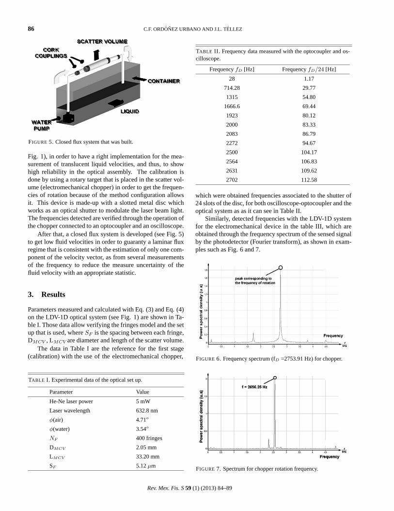
FIGURE 5. Closed flux system that was built.
Fig. 1), in order to have a right implementation for the mea-surement of translucent liquid velocities, and thus, to showhigh reliability in the optical assembly. The calibration isdone by using a rotary target that is placed in the scatter vol-ume (electromechanical chopper) in order to get the frequen-cies of rotation because of the method configuration allowsit. This device is made-up with a slotted metal disc whichworks as an optical shutter to modulate the laser beam light.The frequencies detected are verified through the operation ofthe chopper connected to an optocoupler and an oscilloscope.
After that, a closed flux system is developed (see Fig. 5)to get low fluid velocities in order to guaranty a laminar fluxregime that is consistent with the estimation of only one com-ponent of the velocity vector, as from several measurementsof the frequency to reduce the measure uncertainty of thefluid velocity with an appropriate statistic.
3. Results
Parameters measured and calculated with Eq. (3) and Eq. (4)on the LDV-1D optical system (see Fig. 1) are shown in Ta-ble I. Those data allow verifying the fringes model and the setup that is used, whereSF is the spacing between each fringe,DMCV , LMCV are diameter and length of the scatter volume.
The data in Table I are the reference for the first stage(calibration) with the use of the electromechanical chopper,
TABLE I. Experimental data of the optical set up.
Parameter Value
He-Ne laser power 5 mW
Laser wavelength 632.8 nm
φ(air) 4.71o
φ(water) 3.54o
NF 400 fringes
DMCV 2.05 mm
LMCV 33.20 mm
SF 5.12µm
TABLE II. Frequency data measured with the optocoupler and os-cilloscope.
FrequencyfD [Hz] FrequencyfD/24 [Hz]
28 1.17
714.28 29.77
1315 54.80
1666.6 69.44
1923 80.12
2000 83.33
2083 86.79
2272 94.67
2500 104.17
2564 106.83
2631 109.62
2702 112.58
which were obtained frequencies associated to the shutter of24 slots of the disc, for both oscilloscope-optocoupler and theoptical system as as it can see in Table II.
Similarly, detected frequencies with the LDV-1D systemfor the electromechanical device in the table III, which areobtained through the frequency spectrum of the sensed signalby the photodetector (Fourier transform), as shown in exam-ples such as Fig. 6 and 7.
FIGURE 6. Frequency spectrum (fD =2753.91 Hz) for chopper.
FIGURE 7. Spectrum for chopper rotation frequency.
Rev. Mex. Fis. S59 (1) (2013) 84–89

IMPLEMENTATION AND CALIBRATION OF A LASER DOPPLER VELOCIMETER IN ORDER TO MEASURE LIQUIDS VELOCITY 87
TABLE III. Frequency data measured with the LDV.
FrequencyfD [Hz] FrequencyfD/24 [Hz]
29 1.20
643 28.48
1289.06 53.71
1640.63 68.36
1914.06 79.75
1972.66 82.19
2128.91 88.70
2304.69 96.03
2441.41 101.72
2558.59 106.60
2656.25 110.67
2753.91 114.74
FIGURE 8. Frequency Spectrum for fluid with natural seeding.
FIGURE 9. Frequency spectrum associated with the circulatingfluid.
The measure of the Doppler frequencies with the laservelocimeter using the flux system in the scatter volume andthe subsequent determination of the velocities are shown inthe Table IV. Again, the frequencies are obtained by the scat-tered signal spectra (see Fig. 8 and 9).
TABLE IV. Values which are determined for circulating fluid.
Frequency kHz Velocity cm/s Velocity ErrorσV (×10−4)
8.50±1.70 4.36 ±8.71
16.99±1.89 8.71 ±9.68
22.40±1.62 11.49 ±8.30
27.80±0.96 14.25 ±4.92
30.98±1.32 15.87 ±6.76
TABLE V. Reynolds numbers calculated.
Velocity Re
1 778.79
2 1316.42
3 2127.18
4 2520.97
5 2761.82
The estimation of the Reynolds number (Re) in Eq. (5)is useful to verify the laminar regime with which flux systemworks. Wherel is the pipe diameter,vP the fluid velocity thatis determined by the technique,ρ the fluid density andµ thefluid dynamic viscosity. TheRe data are dimensionless andare shown in the Table V [2].
Re =ρvP l
µ(5)
3.1. Discussion
It has to note that the calibration as a first stage was reallyuseful in order to know the reliability of the LDV-1D system,since it gave data very close in the methods that were used, sothe error is little. It allows securing and confirming that thisoptical technique is suitable for high accuracy measurementsbecause of the spatial resolution that is handled.
The frequencies spectra of the Figs. 6 and 7 show thatDoppler signals are the result of periodic interruptions to thelaser light passing through the chopper, where it associatesthe rotary frequency with the maximum peak of the radiatedenergy detected, and the weaker peaks (low energy) are as-sociated to shot noise, vibrations of the electromechanicalchopper performance and dark electric currents.
TABLE VI. Error Percentage for calibration measurements
Error Percentage %
1 1.97
2 0.46
3 1.44
4 2.34
5 0.21
6 1.89
7 2.20
Rev. Mex. Fis. S59 (1) (2013) 84–89

88 C.F. ORDONEZ URBANO AND J.L. TELLEZ
Within the measurement velocities stage in the flux sys-tem with optical technique, it is considered several points.The first one is related with burst Doppler signal that holdsa certain width in frequency, it means, there are not a uniquevalue. If it wants to reduce (finer peaks in the frequency spec-trum) can be achieved increasing the scatter volume but itwould have less spatial resolution and with this, more natu-ral or artificial particles through the volume. In this case, thefineness of the Doppler broadening is not relevant because ofthe orders in velocity that are worked.
Another point is to consider a variety of mixed signals asshown in the Fig. 8 and 9, where the most significant peakbelong to a particle which is immersed in the fluid, and itscatters almost all the energy that falls on it (energy of theinterference fringes), and the other peaks are due to particlesthat could be entering and departing in the scatter volume.However, those tiny objects contribute to the scattered sig-nal that is detected, and it can not ensure a unique particlecrossing the interference pattern. There are peaks with lowerheight that can be associated with the noise that was men-tioned above and the vibrations of the pump that pushes theliquid.
For the optimal frequencies processing were made sev-eral measures (150 samples) of the same state, in order to getits histograms. Those histograms (see Fig. 10 and 11) havea lorentzian behavior and it allows to work with mean valuesof the Doppler frequencies to determine the velocities.
As mentioned above, the values in Table IV allow beingcertain of the different velocities that offered the pump and
FIGURE 10. Histogram for Doppler frequency of 30.98 kHz.
FIGURE 11. Histogram for Doppler frequency of 8.50 kHz.
which are determined from Eq. (2). Those velocities arewithin the ranges needed for a flux in a laminar regime insidethe pipe, showing a relative uncertainty below 0.3%, besides,it can see high accuracy in its determination.
The laminar regime was verified from comparing theReynolds number (Re) in table VI with the literatureranges [4], where the first three velocities correspond witha laminar flux, which indicates the correct detection of onecomponent of the velocity vector by the laser Doppler ve-locimeter.
On the other hand, for the other velocities, the pumpstart to exhibit a critic flux behavior or transition regime(Re < 4000) that leads to a turbulent regime, that shouldbe studied with different set up.
4. Conclusions
The use of noninvasive technique to perform different kind ofmeasurements in engineering is a trend that enhances accu-racy and allows us to have high-tech systems.
The reference system with the chopper in the calibrationstage allows verifying the optimal performance of the laserDoppler velocimeter that was implemented, because of lowpercentage error.
The LDV-1D technique implemented provide velocitydata very reliable, since it is taking measures at specificpoints on the fluid, which means better spatial resolution andthe choice of detecting this variable anywhere inside the pipewith a low percentage of error.
Rev. Mex. Fis. S59 (1) (2013) 84–89

IMPLEMENTATION AND CALIBRATION OF A LASER DOPPLER VELOCIMETER IN ORDER TO MEASURE LIQUIDS VELOCITY 89
Nomenclature
λ Wavelenght (m)
fD Doppler frequency (Hz)
φ Angle between incident beams (◦)
Re Reynolds number (nondimensional)
VP Particle velocity (cm/s)
α Angle between flux direction and interference pattern (◦)
SF Fringes spacing (µm)
NF Number of Fringes (fringes)
ro Radius of the laser beam waist (mm)
µ Kinetic viscosity (Pa.s)
ρ density (kg/m3)
F Focal distance (mm)
σV Speed uncertainty(cm/s)
DMCV Diameter of the measuring volume (mm)
LMCV Lenght of the measuring volume (mm)
l Pipe diameter (mm)
1. D. Garcıa i Vizcaıno Sistema laser de medida de velocidadpor efecto Doppler de bajo coste para aplicaciones industri-ales e hidrodinamicas. Tesis Doctoral. (Universitat Politecnicade Catalunya. Barcelona 2005). p.p 34, 36-38, 40
2. C. F. Ordonez Urbano, D. A Dıaz Arteaga, J. Leon Tellez,Es-tudio e implementacion de un anemometro Doppler laser paramedir la velocidad de flujo de lıquidos. (Trabajo de grado en
Ingenierıa Fısica, Universidad del Cauca, Popayan 2006). p.p.37, 58-76.
3. F. Durst, A. Melling, J. H. Whitelaw,Principles and practiceof Laser Doppler Anemometry. Academic Press. (London/NewYork/San Francisco 1976). p.p. 80, 84, 96, 108, 114.
4. C. M. Potter, C. D. Wiggert,Mecanica de fluidos.(Thomson,Mexico, 2002). p.p. 230,231.
Rev. Mex. Fis. S59 (1) (2013) 84–89