IEC 61850 Digital Substation Design Tutorial for...
16
IEC 61850 Digital Substation Design Tutorial for Novices Antonio Riccardo Jr.– National grid Harsh Vardhan–GE Grid Solutions 2019 Texas A&MProtective Relaying Conference
Transcript of IEC 61850 Digital Substation Design Tutorial for...

IEC 61850 Digital Substation Design Tutorial for Novices
Antonio Riccardo Jr. – National grid
Harsh Vardhan– GE Grid Solutions
2019 Texas A&M Protective Relaying Conference

Agenda• Conceptual Design• Proper Data Model & Services• Digita l Substation Arcitecture• Reliability & Redundancy Design• Time Synchronization• Network Traffic Segregation

Conceptual Design -Read… Other Title90-4 IEC/TR 61850-90-4 Network Engineering Guidelines
• Any Concept requires an end result , what is the goal?
• Familiarize yourself with the Standards.
• Read, Read, & Read

Conceptual Design – Read…Learn…• Understand your current organization’s protection and control standards and
practices.
• Utility P & C practices exist for a reason.
• As you work through your standards you will find that certa in aspects of your current design can be improved or simplified.
• Utility practices tend to limit digita l substation design.

Conceptual Design – Read…Learn…Involve…• Involve a ll stakeholders early in your design process.• Pull everyone involved in a power utility system as the yare your customers.
Every one has a job function.• Like every business, know what your customers want , how can you make life
more efficient .• “People fear the future because they do not see their place in it”
Project Manager
Substation Engineering
Protection Technicians
Telecommunication Technicians
Traveling operators
Station Technicians
Digital Substation Design
EMS
Cyber Security
IT
Protection & Control Engineering
Telecomm Engineering

Conceptual Design – Read…Learn…Involve…Invest…• Most essentia l element in the success of implementing a digita l substation• Can be capita lized on projects
Digital Substation
Lab
Prove design
Training
TestingWork with stakeholders
Evaluating equipment
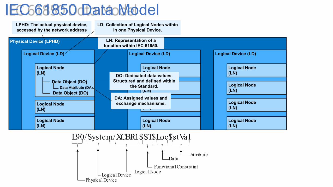
IEC 61850 Data Model
Physical Device (LPHD)
Logical Device (LD)
Logical Node(LN)
Logical Node(LN)
Logical Node(LN)
Data Object (DO)Data Attribute (DA)
Logical Device (LD)
Logical Node(LN)
Logical Node(LN)
Logical Node(LN)
Logical Node(LN)
Logical Node(LN)
Logical Device (LD)
Logical Node(LN)
Logical Node(LN)
Logical Node(LN)
Logical Node(LN)
LPHD: The actual physical device, accessed by the network address
LD: Collection of Logical Nodes within in one Physical Device.
LN: Representation of a function within IEC 61850.
DO: Dedicated data values. Structured and defined within
the Standard.
DA: Assigned values and exchange mechanisms.
Data Object (DO)
L90/System/XCBR1$ST$Loc$stVal
Physical DeviceLogical Device
Logical NodeFunctional Constra int
Data Attribute

IEC 61850 Data Model & Services
64 Boolean, DPS, AnalogGOOSE Inputs
8 SV data streams
LGOS
LSVS
Distance Relay
21 PDIS
PDIS
PTOC
21N
67NRDIR
PTRC
LPHD
LGOS
LSVS
LTMS
LCCH
RFLO
CSWI
System Logical Nodes
ProtectionLogical Nodes
OtherLogical Nodes
PIOC50
RDRE
6x GOCB
4x BRCB
6x URCB
MMS File Transfer
Services
Bay Controller Unit (BCU)
25 RSYN
RREC
RBRF
79
50BF
LPHD
LGOS
LSVS
LTMS
LCCH
CSWI
CILO
System Logical Nodes
Protection Related
Logical NodesControl
Logical Nodes
RDRE
6x GOCB
4x BRCB
6x URCB
MMS File Transfer
Services
64 Boolean, DPS, AnalogGOOSE Inputs
8 SV data streams
LGOS
LSVS

No Standard is Perfect..Other Missing Info – “BlkOpn”, “BlkCls”
CSWI
XCBR
Relay Room
Switchyard

Digital Substation Architecture
Merging Unit + I/O
Merging Unit + I/O
Merging Unit + I/O
Merging Unit + I/O
Merging Unit + I/O
Merging Unit + I/O
Merging Unit + I/O
Merging Unit + I/O
ProtectionRelay
ProtectionRelay
ProtectionRelay
ProtectionRelay
ProtectionRelay
ProtectionRelay
GPS Clock- 2
GatewayHMIEngineering Workstation
Station Bus – RSTP Ring
Process Bus – PRP LAN A (RSTP Ring)
GPS Clock-1
Process Bus – PRP LAN B (RSTP Ring)

Parallel Redundancy Protocol (PRP)
Pros• No network configuration needed• Easily able to connect additional IEDs or plug in for testing
Cons• Multiple network switches required

High Availability Seamless Redundancy (HSR)
Pros• No network configuration needed• Network switches not required, network design less
complex
Cons• Bandwidth limited• Redbox required to connect testing
equipment• Adding IED more difficult

Time SynchronizationProcess bus requires accurate time
synchronization of merging units.• Loss of time synchronization
leads to undesirable protection system performance
Can be rela tive: • individual merging units
synchronized to a given source, e.g. 1 PPS, individual relays
• Merging units synchronized to each other in network
Can be absolute:• External time source to
synchronize merging units• Required for synchrophasors• Better than 1 µsec accuracy
IEEE 1588 -2008• C37.238-2011• IEC 61850-9-3• C37.238-2017
SNTP
From IEC 61850-5

Time Synchronization
PTP PTP PTP PTP PTP PTP PTP PTP PTP PTP PTP PTP
GPS Clock- 2
SNTP, PTP
Merging Unit + I/O
Merging Unit + I/O
Merging Unit + I/O
Merging Unit + I/O
Merging Unit + I/O
Merging Unit + I/O
Merging Unit + I/O
Merging Unit + I/O
ProtectionRelay
ProtectionRelay
ProtectionRelay
ProtectionRelay
ProtectionRelay
ProtectionRelay
GatewayHMIEngineering Workstation
Station Bus – RSTP Ring
Process Bus – PRP LAN A (RSTP Ring)
GPS Clock-1
Process Bus – PRP LAN B (RSTP Ring)
SNTPSNTP, PTP
PTP PTP PTP PTP PTP PTP PTP PTP
PTP PTP PTP PTP PTP PTP
SNTP
PTP PTP PTP PTP PTP PTP PTP PTP

Network Traffic Segregation• Traffic Segregation is important• MAC Filtering• VLANs• ACL
IED A: GOOSE Publishing Parameters

Thank You
Questions?