IDAHO NATIONAL ENGINEERING LABORATORY Managed by the …
49
U4-i^^mm^^J} WTwrn^H^mjoM^t^^'^'*-"' J- *!«i"javp,wjiSJ!F"-*''»'»Wi7't^,"™ -i^JlklT' ^ i. WINCO-1178 September 1993 CONCEPTUAL DESIGN REPORT FOR HANDLING FORT ST. VRAIN FUEL ELEMENT COMPONENTS IDAHO NATIONAL ENGINEERING LABORATORY Managed by the U.S. Department of Energy Prepared for the U.S. Department of Energy Idatio Field Office Under DOE Contract No. DE-AC07-84ID12435 ' w j Westlnghouse Idaho Nuclear Company. Inc. ^ . Idaho Falls, Idaho 83403
Transcript of IDAHO NATIONAL ENGINEERING LABORATORY Managed by the …

U4-i^^mm^^J} WTwrn^H^mjoM^t^^'^'*-"' J- *!«i"javp,wjiSJ!F"-*''»'»Wi7't^,"™ -i^JlklT'
^ i . WINCO-1178
September 1993
CONCEPTUAL DESIGN REPORT FOR HANDLING FORT ST. VRAIN FUEL ELEMENT COMPONENTS
IDAHO NATIONAL ENGINEERING LABORATORY
Managed by the U.S. Department of Energy
Prepared for the U.S. Department of Energy Idatio Field Office Under DOE Contract No. DE-AC07-84ID12435
' w j Westlnghouse Idaho Nuclear Company. Inc. ^ . Idaho Falls, Idaho 83403

\VINCO-1178 UC-510
CONCEPTUAL DESIGN REPORT FOR HANDLING FORT ST. VRAIN FUEL ELEMENT COMPONENTS
R A. Gavalya
September 1993
® Westinghouse Idaho Nuclear Company, Inc.
PREPARED FOR THE DEPARTMENT OF ENERGY
IDAHO OPERATIONS OFFICE UNDER CONTRACT DE-AC07-84ID12435
J N A A S T E R 5<^
DISTRIBUTION OF THIS DOCUMENT iS UNLIMITED

DISCLAIMER
This report was prepared as an account of work sponsored by an agency of the United States Government. Neither the United States Government nor any agency thereof, nor any of their employees, make any warranty, express or implied, or assumes any legal liability or responsibility for the accuracy, completeness, or usefulness of any information, apparatus, product, or process disclosed, or represents that its use would not infringe privately owned rights. Reference herein to any specific commercial product, process, or service by trade name, trademark, manufacturer, or otherwise does not necessarily constitute or imply its endorsement, recommendation, or favoring by the United States Government or any agency thereof. The views and opinions of authors expressed herein do not necessarily state or reflect those of the United States Government or any agency thereof.
DISCLAIMER
Portions of this document may be illegible in electronic image products. Images are produced from the best available original document.

SUMMARY
This report presents conceptual designs for containment of high-level wastes (HLW) and low-level wastes (LLW) that will result from disassembly of fuel elements from the High Temperature Gas-Cooled Reactor at the Fort St. Vrain nuclear power plant in Platteville, Colorado.
Hexagonal fuel elements will enter the disassembly area as a HLW and exit as either a HLW or LLW. The HLW will consist of spent fuel compacts that have been removed from the hexagonal graphite block. Graphite dust and graphite particles produced during the disassembly process will also be routed to the container that will hold the HLW spent fuel compacts. The LLW will consist of the emptied graphite block.
Definitions and general design criteria from the Code of Federal Regulations (CFR) have been included in this report. Design criteria, along with specific requirements for the application were used to develop a conceptual design for the HLW container.
The conceptual design of the HLW container is a stainless steel cylindrical container with a 15 in. diameter and length of 25 in. The can would have a bolted, removable lid with a seal for particulate containment. The removable lid would allow easy reentry into the can if the fuel must be recovered in the future. The can would be both stackable and retrievable. A flush-fitting lid with recessed bolts would permit stacking of the cans. A recessed receptacle in the middle of the lid would receive a bayonet-type stab, allowing retrieval of the can.
Three alternatives have been introduced for interim storage of the HLW containers after the spent fuel has been loaded. The three alternatives are: a) store containers where fuel elements are currentiy being stored (CPP-603), b) construct a new dry storage facility, and c) employ Multipurpose Canisters (currentiy in conceptual design stage).
Containment of the LLW graphite block will depend on several factors: a) LLW classification, b) radiation levels, and c) volume-reducing technique (if used). Packaging may range from cardboard boxes for incinerable wastes to 55-ton cask inserts for remote-handled wastes. If it is determined that the LLW graphite blocks will be taken to the INEL site for disposal, it would be beneficial to meet with Waste Experimental Reduction Facility (WERF) and Radioactive Waste Management Complex (RWMQ pereonnel to determine the preferable container type.
An example of a suitable LLW container is presented, based on the assumption that the emptied graphite blocks will be classified as either Class A, B, or C, and that the graphite blocks would be accepted at WERF for a volume-reducing process using compaction. The LLW container would be a WERF approved B-25 compactor bin capable of holding 12 emptied graphite blocks in the upright position.
Ultimate success of the fuel element disassembly project depends on classification of the emptied graphite blocks. If characterization reveals that classification of the emptied graphite blocks is "greater than Class C", then the emptied graphite blocks will have to be eliminated in a manner similar to HLW.
Before final designs for the containment of the HLW and LLW can be developed, several issues need to be addressed: a) packing factor for fuel compacts in HLW container, b) storage/disposal of loaded HLW containers, c) characterization of the emptied graphite blocks, and d) which technique for volume-reduction purposes (if any) will be used.
iii


CONTENTS
SUMMARY iii
1. INTRODUCTION 1
2. FUEL DESCRIPTION 2 2.1 Fuel Elements 2
2.2 Fuel Con:5)acts 4
3. FUEL ELEMENT DISASSEMBLY 5
4. HIGH-LEVEL WASTE CONTAINMENT 8 4.1 Definition of High-Level Waste 8 4.2 Design Criteria. 8
4.2.1 General Design Criteria. 8 4.2.2 Additional Design Considerations 9
4.3 High-Level Waste Container 9 4.3.1 Requirements 9 4.3.2 Can Design 9
4.4 Criticality 12 4.5 Accountability 12
4.5.1 Sources of Error & Solutions 12 4.5.2 Methods 13
4.5.2.1 Weight 13 4.5.2.2 Delayed Neutron Interrogation 13
5. DISPOSAL ALTERNATIVES FOR SPENT FUEL 14 5.1 Path 1 - Interim Storage at CPP-603 14 5.2 Patii 2 - Horizontal Storage Modules 14 5.3 Path 3 - Multi-Purpose Canisters 15
6. LOW-LEVEL WASTE CONTAINMENT 18 6.1 Definition of Low-Level Waste 18 6.2 Classification of LLW 18
6.2.1 Classification by Long-Lived Radionuclides 20 6.2.2 Classification by Short-Lived Radionuclides 20
6.3 INEL Low-Level Waste Acceptance Criteria 21 6.3.1 ProcessableLLW 21 6.3.2 Non-ProcessableLLW 21
6.4 Low-Level Waste Container 21 6.4.1 WERF Waste Containers 22 6.4.2 RWMC Waste Containers 22 6.4.3 Example of LLW Container 28
7. CONCLUSIONS 30
8. REFERENCES 31
V

APPENDKA A-1
APPENDKB B-1
FIGURES
1. Standard fuel element 3 2. Disassembly products 6 3. HLW containment 7 4. Conceptual design of HLW can 11
5. Disposal alternatives for spent fuel 16 6. DOT 17C steel dram (55-gal) 23 7. WERF compactor bin 24 8. DOT Spec 71-gal square dram 25
9. INEL boxes 26 10. HFEF-5 waste cam (bolted lid) 27 11. Shipping container 29
TABLES
1. Main components of fuel compacts 4
2. Long-lived radionuclides 19
3. Short-lived radionuclides 20
vi

1. INTRODUCTION
Efficient disposal of nuclear wastes has become increasingly important due to the high costs associated with the handling, transport, and elimination of these wastes. Since the development of permanent geologic repositories for nuclear waste is such a cosfly, time-consuming process, maximum utilization of available space in these facilities will be required for the disposal process. Creative methods for the reduction, consolidation, and containment of nuclear wastes must be implemented in order to make the most of available space in these facilities.
SevCTal proposals exist for the permanent disposal of spent nuclear fuel that originated from the High Temperature Gas-Cooled Reactor (HTGR) at the Fort St. Vrain nuclear power plant in Platteville, Colorado. This spent fuel is currentiy being stored as a high-level waste in the Irradiated Fuel Storage Facility (IFSF) located at the Idaho Chemical Processing Plant (ICPP).
Among these proposals is a disassembly process that would separate the spent nuclear fuel from the hexagonal graphite block that served tiie dual purpose of moderator/container for the fuel during the power generation cycle. The resulting products of the disassembly process (fuel compacts, graphite dust and particles, hexagonal graphite block) will be classified as either high-level wastes (HLW) or low-level wastes (LLW). The HLW will consist of the fuel compacts, graphite dust, and graphite particles collected during the disassembly process while the LLW will consist of the emptied graphite blocks.
It is estimated that the HLW from three disassembled standard fuel elements could be placed into a container the size of an intact standard fuel element, based on a packing factor of two-thirds (void space = one-third of container volume). This would result in a 3:1 volume reduction, a significant decrease in space requirements for the storage and disposal of the high-level wastes from the Fort St. Vrain fuel.
If the void spaces of the emptied graphite shell of a standard fuel element are eliminated by a volume-reducing process such as shredding or compacting, the resulting material will occupy approximately 60% of the original volume, a substantial reduction in LLW volume that will optimize use of existing and future LLW facilities.
This report presents conceptual designs for the initial containment of high-level and low-level wastes that will be a result of the disassembly of the Fort St. Vrain fuel elements. Also included in this report are several proposals for the interim storage and permanent disposal of the high-level wastes resulting from this disassembly process.
1

2. FUEL DESCRIPTION
Currentiy 726 Fort St. Vrain fuel elements (nuclear fuel plus graphite block) are in dry storage at the Irradiated Fuel Storage Facility (CPP-603). There arc 1482 remaining fuel elements in storage at the Fort St. Vrain power plant. The combined total of 2208 fuel elements consist of three main types. They are:
Standard fuel element (1878) • Control rod fuel element (275) • Bottom control rod fuel element (55)
2.1 Fuel Elements
The spent nuclear fuel is contained in hexagonal graphite blocks that are 14.2 inches across the flats and 31.2 inches in length. Within the hexagonal graphite blocks are:
• fuel compacts • fuel holes (to hold fuel compacts)
coolant flow channels • poison holes • control rod holes • reserve shutdown hole • pickup hole for handling
The standard fuel elements (85% of total fuel elements) contain fuel compacts, fuel holes, coolant flow channels, poison holes, end a pickup hole for handling purposes. The control rod and bottom control rod fuel elements contain all of the above seven features listed within the graphite blocks. The control rod fuel elements comprise about 12.5% of the total fuel elements while the bottom control rod fuel elements complete the remaining 2.5% (for details of the Fort St. Vrain fuel elements, refer to Table A-1 in Appendix A).
An intact standard fuel element (see Fig. 1) occupies a space of 5430 in . When a standard fuel element is disassembled, the displacement volume of the fuel compacts will be approximately 1220 in . The void volume within the graphite block after the compacts are removed is about 2380 in3. This void volume occupies nearly 44% of the space currently needed to contain the fuel element (for void volumes of fuel elements, refer to Table A-2 in Appendix A).
2

14.172
(B) pictorial
L - A
1-in. clearance
0.875
Coolant hole 0.625 dia. (102)
Coolant hole 0.500 dia. (6)
Burnable poison 0.005 dia. (6)
Fuel hole 0.500 dia. (210)
Cemented graphite plug (typ)«
Fuel handling
Helium fbw (typ)
Burnable poison
Coolant channel
Fuel rod 29.5-in. length
Sec. A-A Dowel socket
Elgure 1. Standard fuel element

2.2 Fuel Compacts
The spent nuclear fuel is made up of uranium and thorium particles coated with layers of pyrolytic carbon and silicon carbide. These coated particles are then loosely bonded by a carbonaceous matrix material to form cylindrical compacts that are 0.49 in. in diameter with a length of 1.94 in. The fuel compacts are inserted end-to-end in the fuel holes and sealed at each end with a graphite plug to hold the compacts in place. These stacked fuel compacts form a fuel rod. In a standard fuel element, this fuel rod is 29.5 in. long.
Westinghouse Idaho Nuclear Company (WINCO) supplied information! regarding the makeup of the fiiel compacts. The main components of the fuel compacts, based on end-of-life (EOL) statistics are listed in Table 1.
Table 1. Main components of fuel compacts (EOL).
Element Maximum average per fuel segment (grams/compact)
Minimum average per fuel segment (grams/compact)
Mean average per fuel segment
(grams/comp)
U-233 U-235 U-235 equiv Th-232
Carbon
Silicon
0.069 0.178 0.316
3.82
7.7
1.28
0.022 0.036 0.080
3.16
7.7 —
0.052 0.075 0.179
3.45
7.7 ~
There are 3132 compacts per standard fuel element, 1782 compacts per control rod block, and 1302 compacts per bottom control rod block. The maximum mass of lJ-235 equivalent in a standard fuel element is nearly 1 kilogram while the maximum mass of carbon is slightiy over 24 kilograms. For criticality purposes, the maximum average values for U-235 equivalent will be used.
4

3. FUEL ELEMENT DISASSEMBLY
The intact fuel element will enter the work area (hot cell) as HLW whereas the disassembled fuel element will exit the hot cell as both HLW and LLW (see Fig. 2). The HLW will consist of the spent fuel compacts that have been pushed out of the graphite block along with the graphite dust and graphite particles generated during the drilling process. The LLW will be the emptied graphite block.
The fuel element will be placed on an X-Y-Z table where the disassembly process will begin. The graphite plugs (which hold the fuel compacts in place) will be drilled out, creating graphite dust and graphite particles. Since the depths of the graphite plugs may vary, the drill bit could occasionally remove portions of the fuel compacts during removal of the graphite plugs which would lead to contamination of the graphite dust and particles. The graphite dust created during the drilling process will be vacuumed through a hole in the drill bit and routed via ductwork to a HLW container (referred to as a can). The larger graphite particles that chip off during the drilling process will also be channeled into the same can.
When drilling is completed, spent fuel compacts will be pushed out of the fuel holes with a ram. Spent fuel compacts and graphite particles that break off during this part of the process will be funnelled into the same HLW can that is holding the graphite dust and graphite particles from the drilling process. If rupturing of fuel kernels within the fiiel compacts is of concern, the fuel holes could be reamed to remove any radioactive contaminants that might be adhering to the walls of the fuel holes. Reaming would also remove radioactive contaminants that might have migrated into the graphite block. Products from this process would also enter into the HLW can.
When the can is full, it will be capped and transferred to a material balance area for accounting purposes. The HLW can may then be moved to areas set aside for characterization and labeling. After these processes are complete, the can will be placed in either a holding area of the hot cell or loaded directiy into a storage canister (see Fig. 3). This will serve as the first step in the high-level waste containment process.
After all of the fuel compacts have been removed from the fuel element, the emptied graphite block will be transferred from the X-Y-Z table and placed in a LLW containment area for packaging or further processing (volume-reduction).
Prior to disassembly, the loaded fuel element will be weighed along with the empty can. The can will be weighed again after it has been filled with HLW. The emptied graphite block will also be weighed. The weight of the material removed from the fuel element should equal the weight of the material that has been collected in the can. The comparison of weights will be the primary method used for accounting puiposes. If necessary, a secondary method for accounting purposes could be accomplished with the use of a Delayed Neuti on Interrogator (DNI). In this method, the canned fuel compacts would be characterized and compared with shipper's data.
5

nuvv
Fuel Element: Fuel Compacts and Graphite Block
/ o 0 0 0 o o o / e 0 0 0 0 0 0 . .
/ o o o o o o o o o . / O 0 0 0 0 0 0 0 0 0 .
/ O O O O O O O O O O O ' I / O 0 O O 0 0 0 0 0 O 0 0 >
/ O O O O O O O O O O O O O /o o o o o o o o o o o o o o \0 o o o o o o o o o o o o \0 0 0 0 0 0 0 0 0 0 0 0 ' \0 0 0 0 0 0 0 0 0 0 0 \0 0 0 0 0 0 0 0 0 0 \ o o o o o o o o o
\ 0 0 0 0 0 0 0 -. 0 0 0 0 0 0 0
t HLW
Fuel Compacts
LLW Emptied Graphite Block
Graphite Dust / o o o o o o o x
/ O 0 0 0 0 0 0 o \ / O 0 0 0 0 0 0 0 o \
/ o o o o o o o o o o \ /O 0 0 0 0 0 0 0 0 0 o\ /O 0 0 0 0 0 0 0 0 0 0 o\
/ o o o o o o o o o o o o o . ( 0 0 0 0 0 0 0 0 0 0 0 0 0 0 ) \ o o o o o o o o o o o o o / \0 0 0 0 0 0 0 0 0 0 0 o/ \0 0 0 0 0 0 0 0 0 0 0/ \ o o o o o o o o o e / \ 0 0 0 0 0 0 0 0 o / \ 0 0 0 0 0 0 0 0 / \ O 0 0 0 0 0 0 '
Graphite/Fuel Particles
Figure 2. Disassembly products.
6

DISASSEMBLY WORK AREA
h^-15—H
~Cap and seal Can. Transfer to Mass
Balance Area
Place Cans in Transfer Cask/Storage Canister
MATERIAL BALANCE AREA
•
® Transfer
Cask
1. Weigl 2. Label
GPP - 603
® Storage Canister
Horizontal Storage Module
® Storage Canister
Multi - Purpose Canister
Figure 3. HLW containment.
7

4. HIGH-LEVEL WASTE CONTAINMENT
The HLW can will interface with the equipment used to disassemble the Fort St Vrain fuel elements. The can will be the first step in containing the fuel compacts, graphite dust, and graphite particles that are a result of the disassembly process. In this section, design criteria for HLW packages are listed and a conceptual design for the HLW can is presented. Accountability methods will also be discussed.
4.1 Definition of High-Level Waste
High-Level Waste, as defined in the Code of Federal Regulations^, means the material is one of the following:
• Irradiated reactor fuel
• liquid wastes resulting from the operation of the first cycle solvent extraction system, or equivalent, and the concentrated wastes from subsequent extraction cycles, or equivalent, in a facility for reprocessing irradiated reactor fuel, and
• solids into which such liquid wastes have been converted.
4.2 Design Criteria
Due to the inherent hazards associated with nuclear wastes, many factors should be considered when designing a high-level waste package. General design criteria for high-level waste packaging from the Code of Federal Regulations are outlined along with additional considerations from Regulatory Guide 3.61.
4.2.1 General Design Criteria
General design criteria for high-level waste packages, as stated in the Code of Federal Regulations , are:
• Packages for HLW shall be designed so that the in situ chemical, physical, and nuclear properties of the waste package and its interactions with the emplacement environment do not compromise the function of the waste packages or the performance of the underground facility or the geologic setting.
• The design shall include but not be limited to consideration of the following factors: solubility, oxidation/reduction reactions, corrosion, hydriding, gas generation, thermal effects, mechanical strength, mechanical stress, radiolysis, radiation damage, radionuclide retardation, leaching, fire and explosion hazards, thermal loads, and synergistic interactions.
• Waste packages shall be designed to maintain waste containment during transportation, emplacement, and retrieval.
• A label or other means of identification shall be provided for each waste package. The identification shall not impair the integrity of the waste package and shall be applied in such a way that the information shall be legible at least to the end of the period of retrievability (from a geologic repository).
8

4.2.2 Additional Design Considerations
Another useful document for reference when actual storage containers are designed is Regulatory Guide 3.61 (Task CE 306-4) entitled "Standard Format and Content for a Topical Safety Analysis Report for a Spent Fuel Dry Storage Cask". Issues that should be addressed during the design stage as outiined in this document are:
Spent fuel - physical, thermal, and radiological characteristics of the spent fuel Structural design - load combinations, stresses and strains
Weight - total weight of container and contents
Chemical and galvanic reactions - possible chemical or galvanic reactions between the container and its contents
Positive closure - covers fit tight, can't be opened accidentally Lifting devices - capable of supporting container Thermal design - pressures, temperatures, thermal expansion Criticality - design container to stay sub-critical when loaded with fuel.
4.3 High-Level Waste Container
The HLW container, referred to as a can, will receive the fuel compacts, graphite dust, and graphite particles that are a result of the fuel element disassembly process. After filling, the cans may then be placed in a storage canister. The storage canister, filled with cans, will have a variety of paths to follow for permanent disposal.
4.3.1 Requirements
Due to the specialized nature of the disassembly process and handling, the HLW can must be designed to meet certain requirements. The can must be:
Stackable - able to stack on top of each other
Retrievable - able to retrieve cans from storage canister
Strong - able to support weight of stacked cans
Compatible with storage canister
Sealed - keep particulates contained Sub-critical when filled with HLW.
In addition, the lid of the can might be: Flush-fitting with sides of can Removable
Designed to be used as a lifting device.
4.3.2 Can Design
A possible conceptual design of the can may be a stainless steel cylindrical container with a 15 in. diameter and length of 25 in. (see Fig. 4). The can could have a bolted, removable lid with a seal for particulate containment. This would allow easy reentry into the can if the fuel must be recovered in the future.
9

The HLW can should be both stackable and retrievable. This can be accomplished by recessing the bolts that fasten the lid to the container and placing a recessed receptacle in the middle of the lid. The recessed receptacle will receive a bayonet-type stab that will permit easy retrieval of the cans from the storage canister if the need arises.
The lid should fit flush with the sides of the can to minimize wasted space and provide a tighter fit within a mating storage canister. It must also be capable of supporting five to seven cans stacked end-to-end. The static load that it would have to support might be in excess of 1000 pounds. The lid should be self-aligning with the can body to position the lid such that the bolts are lined up properly when the fastening process begins. Centering pins will serve to accomplish this task.
Cans must also be sized to fit the storage canister into which they will be placed. If cans fit too loosely, space within the storage canister would be used inefficientiy. During transport, the cans would have a tendency to move within the storage canister or transfer cask which might lead to damage of the cans or transfer device. Tight fitting cans within the storage canister would also aid in the retrieval process since the recessed receptacle in the lid would be in the center of the storage canister. As the bayonet-type stab is lowered into the storage canister, positive location and coupling with the receptacle would be more certain.
An advantage of the smaller can is that ready access would be provided if it were necessary to re-examine or reconfigure the spent nuclear fuel contained within die cans. The small size and weight of the cans will facilitate handling while providing more flexibility for storage and disposal.
10

Seal
Receptacle
Stainless steel
Bayonet-type stab
15"
Cross-Section View
Top View
Figure 4. Conceptual design of HLW can.
11

4.4 Criticality
Generic criticality studies of uranium/graphite systems were performed by EG&G personnel in the Reactor and Radiation Physics department. These studies were used for scoping purposes in determining dimensions of the HLW can. If a cylinder with a diameter of 15 in. and length of 30 in. is completely filled with compacts from the Fort St. Vrain fuel elements and assuming that there are no void spaces in the filled cylinder, the amount of U-235 equivalent would be 4.36 Kg while the amount of carbon would be 105.9 Kg. An inspection of the criticality data in Table 12 ("Summary of KENO-V.a results for the dry mixtures in cylindrical geometry with a vacuum boundary condition.") of the study^ shows that for a kcff of 0.956 ± 0.003, the mass of U-235 is approximately 280 kilograms with a graphite mass of 115.4 kilograms for a 15 by 30 in.cylinder. This is far more than the amount of U-235 equivalent mass that would be contained in the can with no void spaces. This comparison indicates that the contents of the HLW can would be in a sub-critical configuration given that: a) the mixture is dry, and b) there is a vacuum boundary.
Since this is a conceptual design, the dimensions of the can and the stacking configuration of the cans under different conditions would have to be verified from a criticality standpoint before a final design could be approved.
4.5 Accountability
It is essential that strict accountability be maintained to prevent accumulations of U-235 that might result in a critical mass. The mass of the intact fuel element should equal the combined masses of its disassembled components (graphite block + spent fuel compacts + graphite chips + graphite dust). A separate material balance area will be set aside in the hot cell for accountability measurements
4.5.1 Sources of Error and Solutions
Several reasons why mass imbalances might occur arc:
• Graphite dust, graphite particles, fuel compacts collect in ductwork, crevices
• Spillage - can is overfilled, compacts spill onto floor
Weighing scales arc not calibrated
• Shift changes - new shift arrives, continuity of operation disrupted.
Some possible solutions to the above problems might be: • Design flow systems such that minimal amounts of dust, particles, compacts collect
in ductwork or filters • Install "knocker" that taps walls of ductworic at regularly spaced time intervals
• Mount remote camera such that loading can be visually monitored
Calibrate scales on regular basis
• Develop standard operating procedures (SOPs) that address shift change policies
• Provide interlocks, alarms, and/or indicators to alert operating personnel of improper loading procedures
• Install trays to collect spillage.
12

4.5.2 Methods
The two principle methods that could be used for accounting purposes of the Fort St. Vrain fuel elements are:
Weight • Delayed neutron interrogation (DNI).
A discussion of these two methods follows.
4.5.2.1 Weight. The most straightforward approach would be the weight method. Fuel elements would be weighed before and after disassembly to maintain a record of how much material (nuclear fuel, graphite dust, graphite particles) has been removed from the graphite block. Cans would also be weighed before and after loading. The weight of material removed from the graphite block should equal the weight of the material loaded into the can. If there are any discrepancies, it might indicate that there is a problem in record keeping; dust, particles, or fuel compacts are trapped in the ductwork or filters; or that some spillage may have occurred.
4.5.2.2 Delayed Neutron Interrogation. If deemed necessary, a cross check for accountability puiposes would be the use of a delayed neutron interrogator (DNI). The DNI would measure the U-235 fissile material content of the Fort St. Vrain HLW contained in the cans. The amount of fissionable material in the cans will be compared to the amount of fissionable material provided by the original shipper's data for the Fort St. Vrain fuel elements.
A neutron source induces neutron-rich fission products in U-235 fissile material. After removing the neutron source, a count is made of delayed neutrons from the neutron-rich fission products. The number of delayed neutrons is proportional to the number of induced fissions which in turn is proportional to the amount of fissionable material present.
If this system is used, an area would have to be set aside in the hot cell or adjacent to the hot cell in order to accommodate the equipment necessary to perform a delayed neutron interrogation. The DNI would require a crane for handling purposes, computers, and other specialized equipment.
13

5. DISPOSAL ALTERNATIVES FOR SPENT FUEL
Currentiy, Fort St. Vrain fuel elements are being stored at the Irradiated Fuel Storage Installation (CPP-603) in storage canisters made of 1/4-in. thick carbon steel pipe. The canisters have an inside diameter of 17.5 in. and are 129 in. long. Four fuel elements are held in each canister. The fuel elements were transported from the Fort St. Vrain power plant in a transfer cask that held six fuel elements.
Many options can be employed for disposal of the HLW cans once spent fuel has been loaded. Three separate paths for disposal of the spent fuel are listed below (Fig. 5).
5.1 Path 1 - Interim Storage at CPP-603
In this pathway, the transfer cask used to transport fuel elements from the Fort St. Vrain powerplant would be utilized to move six fuel elements (31.2 in. length) from CPP-603 to an unloacUng bay at the fuel disassembly hot cell. The fuel elements would then be disassembled into high and low-level wastes. The HLW would be canned, labeled, and placed in the loading bay of the hot cell. Seven HLW cans (25 in. length) of spent fuel would then be loaded into the transfer cask and transported to the loading/unloading facility at CPP-603.
At CPP-603, the cans would be unloaded from the transfer cask and placed into the original carbon steel storage canister. The storage canister will hold five of the 25-in. high cans, leaving a surplus of two cans which will partially fill a second storage canister. The process will then be repeated until all the cans have been transfeircd.
It may be possible that the shielding on the original transfer cask will be inadequate due to the higher concentration of radioactive materials in the cans. If this is the case, a shielding overpack may have to be added to ensure that radioactivity levels will be held to an acceptable level during transport of the canned fuel. Criticality calculations would also have to be performed to verify that this would be a safe configuration for both transport and storage.
The advantage of this pathway is that there is already an interim storage area for high-level wastes. When the final disposition for the stored high-level wastes has been determined, the cans may be easily transferred into containers for transport and permanent storage.
5.2 Path 2 - Horizontal Storage Modules
An interim storage system similar to the NUHOMS® method developed by Pacific Nuclear would be used in this approach.
Four fuel elements at CPP-603 would be loaded into a new stainless steel storage canister that has been designed to interface with a new mating transfer cask. This new stainless steel storage canister would be about the same size (17.5 in. I.D., 129 in. long) as the carbon steel storage canisters that the fuel elements are currentiy being stored in at CPP-603.
The loaded storage canister would then be placed into the mating transfer cask and transported to the hot cell loading/unloading bay. The fuel elements would be unloaded and moved into the hot cell work area where the fuel elements would be disassembled into high and low-level wastes. The high-level wastes would be canned and placed in the loading/unloading bay of tiie hot cell.
Five HLW cans would be loaded into the storage canister which would then be sealed. The storage canister would then be reloaded into the mating transfer cask. The transfer cask would be
14

transported to an interim dry storage facility. The sealed storage canisters would be unloaded and stored either horizontally or vertically, depending on the needs of the facility. When an acceptable geologic repository has been determined, the se^ed storage canisters could be transferred there for permanent disposal.
5.3 Path 3 - Multi-Purpose Canisters
Another option that should be considered would be the placement of the HLW cans into a Multi-Purpose Canister (MPC). These MFCs are currentiy in the conceptual design stage and will conceivably hold 35 intact Fort St. Vrain fuel elements. There would be seven columns of fuel elements stacked five high in the MPC. The columns will be separated by 'poison baskets' for criticality purposes. If the fuel elements are disassembled, and the spent fuel is placed into cans with a volume reduction of 3:1, the equivalent of slightiy more than 100 fuel elements could be placed into an MPC.
Six fuel elements would be loaded into the original Fort St. Vrain fuel transfer cask. The transfer cask would transport the six fuel elements from CPP-603 to an unloading bay at the fuel disassembly hot cell. The fuel elements would then be disassembled into high and low-level wastes. The HLW would be canned and placed in the loading bay of the hot cell. The cans of spent fuel would then be loaded into the tiansfer cask and transported to an MPC handling facility (a 120 ton crane will be necessary for handling purposes).
At the MPC handling facility, six of the 25-in. cans will be loaded in each column for a total of 42 cans. The MPC will then be packaged in its shielded overpack and transported to temporary shielded storage at a DOE site. "The MPC will be unloaded and stored until a permanent storage location for the MPC is determined.
Again, it would be necessary to evaluate the shielding on the original transfer cask to determine if it would be adequate for the more concentrated radioactive materials in the cans. Criticality, shielding, and thermal evaluation studies would also have to be performed to determine if the use of the MPC would be feasible due to the more concentrated high-level wastes contained in the cans. Preliminary studies have indicated that there won't be any criticality, shielding, or thermal problems if 35 intact Fort St. Vrain fuel elements are loaded into the MPC.
15

o Load SIX fuel elements into transfer cask originally used to transport fuel elements from FSV to the INEL
Hot Cell Fuel Element Disassemoly Station
• ^ -
Transfer cask shipped to hot cell area eittier by rail or truck
Transfer cask received at the hot cell unloading bay Elements unloaded from transfer cask, rrraved to hot cell for disassembly
Fuel compacts rerrxjved from fuel 6lerr>9nt and placed in can
Place cans of grapNte dust arxf fuel compacts into transfer cask
• ^ ^
Move cans from transfer casi back to original dry siornge containers
CPP-603 Fuel compacts and graphite dust are stored in CPP-603 (IFSF)
CPP-603
FSV fuel elements stored in carbon steel storage canisters. Four elements per canister.
VZZ7.
/ / /
Ld
©
Hot Cell Fuel E:lement Disassembly station
fl \r^
Fuel compacts umoved from fuel elemsnt and placed in can Transfer cask shipped to interim
storage facility
\
Storage canisters loaded with cans of fuel compacts and graphite dust are placed for transport in casks and shipped to a permanent repository
Load fuel elements into storage canister and place storage canister in transfer cask
Transfer cask received at the hot cell unloading bay Elements unloaded from transfer cask, moved to hot cell for disassembly
Place cans of graphite dust and fuel compacts into storage container Storage container is then placed in transfer cask
Transfer to geological repository
© See next page
Horizontal storage rroduie facility
Figure 5. Disposal alternatives for spent fuel.
16

CPP-603
FSV fuel elements stored in carbon steel storage canisters. Four elements per canister.
W^
-&^
© Transfer cask received at the hot cell unloading bay Elements unloaded from transfer cask, nxjved to hot cell for disassembly
Place cans of graphite dust and fuel cornp acts into stainless steel storage container Storage cimtainer is then placed in transfer cask
Load fuel elements into new sta'niess steel canister and place
storage container in transfer cask
X
At MPC handling facility unload S S canisters from transfer cask and place in MPC MPC is then loaded into shielded overpack
Hot Cell Fuel Element Disassembly Station
a ri_i_ \r\^ Transfer cask received at the hot cell unloading bay Elements unloaded from transfer cask, moved to fiot cell for disassembly
w Fuel compacts removed from fuel element and placed in can
Transport to MPC handling facility
4
I 5:5
tor Transport MPC to HSM facility
Figure 5. Continued.
17

6. LOW-LEVEL WASTE CONTAINMENT
There are four classifications of low-level radioactive waste as defined in the Code of Federal Regulations: Class A, Class B, Class C, and greater than Class C. As class levels increase (Class A —> greater than Class C), requirements for disposal become increasingly stringent. Class A wastes must meet minimum requirements for disposal (no cardboard or fiberboard packaging, solidify liquid wastes, no toxic wastes, etc.) whereas greater than Class C wastes are generaSy not acceptable for near-surface disposal and must be disposed of in a geologic repository.
Classification of the emptied graphite blocks will depend on which radionuclides are present and their respective curie concentrations in the emptied graphite blocks. This section presents proposals for containment of these LLW graphite blocks, based on the assumption that classification of the emptied graphite blocks are Class C or lower. If the blocks are classified as greater than Class C, methods for disposal will be similar to that of high-level wastes.
A definition of LLW follows along with classification criteria for the different classes of LLW.
6.1 Definition of Low-Level Waste
According to the Code of Federal Regulations^, low-level radioactive waste means radioactive material that:
(1) Is not high-level radioactive waste, spent nuclear fuel, or byproduct material (as defined in section IIe(2) of the Atomic Energy Act of 1954, (42 U.S.C. 2014(e)(2))); and
(2) The NRC, consistent with existing law and in accordance with paragraph (a), classifies as low-level radioactive.
A quote from the Waste Management 90 convention states; "LLW consists of radioactive materials and other materials that have been in contact with the radioactive materials and thus are contaminated or suspected of being contaminated. It is generated in many forms, concentrations, and amounts. It ranges from trash that may be only slightly contaminated with radioactivity to highly radioactive materials such as activated structural components from nuclear power reactors. LLW ranges in activity from thousands of curies per cubic meter to less than a few microcuries per cubic meter".
6.2 Classification of LLW
Four classifications of LLW are defined in the Code of Federal Regulations^: Class A, Class B, Class C, and greater than Class C. Classifications are based on two considerations:
(1) The concentration of long-lived radionuclides (and their shorter- lived precursors) whose potential hazard will persist long after such precautions as institutional controls, improved waste form, and deeper disposal have ceased to be effective. These precautions delay the time when long-lived radionuclides could cause exposures. In addition, the magnitude of the potential dose is limited by the concentration and availability of the radionuclide at the time of exposure.
(2) The concentration of shorter-lived radionuclides for which requirements on institutional controls, waste form, and disposal methods are effective.
18

Class A waste is waste that is usually segregated from other waste classes at the disposal site. The physical form and characteristics of Class A waste must meet the minimum requirements set forth in 10 CFR §61.56(a). If Class A waste also meets the stability requirements set forth in 10 CFR §61.56(b), it is not necessary to segregate the waste for disposd.
Class B waste is waste that must meet more rigorous requirements on waste form to ensure stability after disposal. The physical form and characteristics of Class B waste must meet both the minimum and stability requirements set forth in 10 CFR §61.56.
Class C waste is waste that not only must meet more rigorous requirements on waste form to ensure stability but also requires additional measures at the disposal facility to protect against inadvertent intrusion. The physical form and characteristics of Class C waste must meet both the minimum and stability requirements set forth in 10 CFR §61.56.
Waste that is not generally acceptable for near-surface disposal (greater than Class C) is waste for which form and disposal methods must be different, and in general more stringent, than those specified for Class C waste. In the absence of specific requirements in this part, such waste must be disposed of in a geologic repository as defined in part 60 of 10 CFR unless proposals for disposal of such waste in a disposal site licensed pursuant to this part are approved by the commission.
Tables 2 and 3 list long-lived and short-lived radionuclides upon which classifications are based."
Table 2. Long-lived radionuchdes
Radionuclide
C-14 C-14 in activated metal Ni-59 in activated metal Nb-94 in activated metal Tc-99 1-129 Alpha emitting transuranic nuclides with half-life greater than 5 years Pu-241 Cm-242
Concentration (curies/m3)
8.0 80.0
220.0 0.2 3.0 0.08
lOOa
3,500a 20,000a
a. Units are nanocuries per gram
19

Table 3. Short-lived radionuclides.
Radionuclide
Total of all nuclides with less than 5 year half-life H-3 Co-60 Ni-63 Ni-63 in activated metal Sr-90 Cs-137
C o l l
700
40 700
3.5 35 0.04 1
Concentration (curies/m3)
Col. 2
a
a a 70
700 150 44
Col. 3
a
a a
700 7000 7000 4600
a. There are no limits established for these radionuclides in Class B or C wastes. Practical considerations such as the effects of external radiation and internal heat generation on transportation, handling, and disposal will limit the concentrations for these wastes. These wastes shall be Qass B unless the concentrations of other nuclides in Table 3 determine the waste to be Class C independent of these nuclides.
6.2.1 Classification by Long-Llved Radionuclides
If radioactive waste contains only radionuclides listed in Table 2, classification shall be determined as follows:
(i) If the concentration does not exceed 0.1 times the value in Table 2, the waste is Class A.
(ii) If the concentration exceeds 0.1 times the value in Table 2 but does not exceed the value in Table 2, the waste is class C.
(iii) If the concentration exceeds the value in Table 2, the waste (greater than Class C) is not generally acceptable for near-surface disposal.
(iv) For wastes containing mixtures of radionuclides listed in Table 2, the total concentration shall be determined by the sum of fractions rule described in paragraph (a)(7) of 10 CFR §61.55.
6.2.2 Classification by Short-Llved Radionuclides
If radioactive waste does not contain any of the radionuclides listed in Table 2, classification shall be determined based on the concentrations shown in Table 3. However, if radioactive waste does not contain any nuclides listed in either Table 2 or 3, it is Class A.
(i) If the concentration does not exceed the value in Column 1, the waste is Class A.
(ii) If the concentration exceeds the value in Column 1, but does not exceed the value in Column 2, the waste is Class B.
(iii) If the concentration exceeds the value in Column 2, but does not exceed the value in Column 3, the waste is Class C.
(iv) If the concentration exceeds the value in Column 3, the waste (greater than Class C) is not generally acceptable for near-surface disposal.
(v) For wastes containing mixtures of the nuclides listed in Table 3, the total concentration shall be determined by the sum of fiactions rule described in paragraph (a)(7) of 10 CFR §61.55.
20

Mixtures of long-lived and short-lived radionuclides can also be classified by following the instructions in 10 CFR §61.55. The sum of Auctions rule is also outlined in this section of the CFR.
6.3 INEL Low-Level Waste Acceptance Criteria
Certain criteria must be met before emptied graphite blocks from the Fort St. Vrain fuel disassembly project will be accepted for LLW processing at the Waste Experimental Reduction Facility (WERF). Other criteria apply for LLW disposal at the Radioactive Waste Management Complex (RWMC). The INEL Low-Level Radioactive Waste Acceptance Criteria Manual(WAC)8 provides criteria for acceptance of LLW at the INEL.
In the INEL Low-Level Radioactive Waste Acceptance Criteria Manual, LLW is separated into two main categories: a) LLW that can be processed, and b) LLW that is not eligible for processing. LLW that can be processed is directed to the Waste Experimental Reduction Facility (WERF) whereas non-processable LLW goes directiy to the Ra<Uoactive Waste Management Complex (RWMC).
6.3.1 Processable LLW
Processable low-level radioactive solid waste falls into one of the following categories:
• Incinerable waste • Compactible waste • Processable, low density, noncompactible metallic waste for recycling or volume
reduction and disposal
6.3.2 Non-Processable LLW
Non-processable low-level radioactive waste are in the following categories, depending on the characterization of the waste material:
• Contact-handled waste
• Remote-handled waste.
Tables 1 - 5 in the WAC manual establish limits for radiation, contamination, TRU material, fissionable material, C-14, and tritium. These tables also establish guidelines for container types and dimensions. For quick reference, these tables are included in Appendix B.
6.4 Low-Level Waste Container
Packaging for LLW depends on several factors. Some factors that should be considered are:
• Eligibility of LLW for volume reduction
• Radiation levels of LLW
• Shippers needs
• Depository requirements.
Packaging ranges from cardboard boxes for incinerable wastes to 55-ton cask inserts for remote-handled wastes. Examples of containers that might be used for packaging the LLW graphite blocks are presented in the following sections. For further examples of containers that could be used for packaging of either processable or non-processable LLW, see Reference 9.
21

Before deciding on a final package for the graphite blocks, it would be beneficial to meet with WERF and RWMC personnel to determine the preferable container type. They would provide guidance for preferred packaging once classification of the emptied graphite blocks is determined.
6.4.1 WERF Waste Containers
The graphite blocks may be eligible for a volume-reducing process such as incineration or compaction. As noted in the introduction, the volume occupied by the graphite block could be reduced by more than 40% if void spaces within the graphite block are removed.
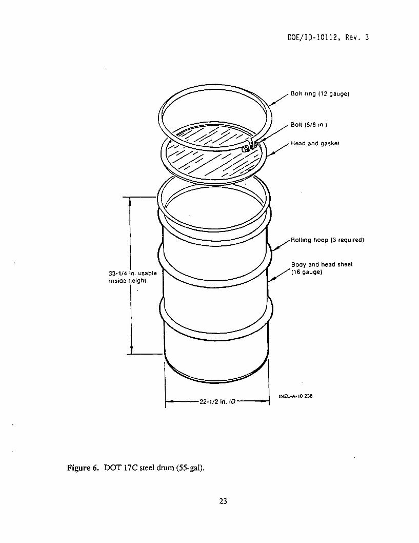
Containers acceptable for incinerable wastes are: DOT 17C steel drum - 55 gal
• Corrugated cardboard box (60 lbs/box, 2 x 2 x 2 ft). Acceptable containers for compactible waste are: • Polyethylene bag (60 lbs/bag)
B-25 bin - 6000 lb/bin, 4 x 4 x 6 ft.
Figures six and seven are examples of containers^ that could be used for packaging emptied LLW graphite blocks if volume-reduction is incorporated into the process.
6.4.2 RWMC Waste Containers
If the graphite blocks are submitted to the RWMC for direct disposal, there are many containers that would be acceptable for packaging of the LLW.
Several options for contact-handled packaging include: DOT steel drums - 30,55,71 gal INEL plywood boxes - 6000 lb/box
2 x 4 X 8 ft 4 X 4 X 4 ft 4 X 4 X 8 ft.
Some options for remote-handled packaging include: HFEF-5 canister - 1000 lb/canister, 1 x 6 ft
• 55-Ton insert -12,(XX) IbAinsert, 4 ft diameter x 8 ft high TRA resin tank - 20,000 lb/tank, 6 ft diameter x 7 ft high.
Figures eight, nine, and ten are examples of LLW containers^ that could be used for packaging the graphite blocks if direct disposal at RWMC is required.
22
DOE/ID-10112, Rev. 3
33-1/4 in. usable inside height
Bolt ring (12 gauge)
Bolt (5/8 in )
Head and gasket
Rolling hoop (3 required)
Body and head shent (16 gauge)
INEL-A-10 238
Figure 6. DOT 17C steel drum (55-gal).
23

DOE/ID-10112, Rev. 3
"NucFil" filter
Structural re-inforcing
Figure 7. WERF compactor bin.
"Seal-loc" closure
Sides, top, ends & bottom 12 gauge steel
7.6636
24

DOE/ID-10112, Rev. 3
Bolt ring-12 ga.
Bolt • 5/8 in.
Cover-18 or 16 ga.
Gasket • ethylene propylene
Rolling hoops - as required
Body and head sheet • 18 or 16 ga.
Inside dia. • 22'/i in.
Inside height • 33 V* in.
7^474
Figure 8. DOT Spec 71-gal square drum.
25

DOE/ID-10112, Rev. 3
Bands typical
•3 ^T" or ^ 4 X 4 X 8 ft, 4000- and 6000-lb box
"XT 4 X 4 X 4 ft, 6000-lb box
a • ^ I f 2 X 4 X 8 ft, 6000-lb box
INEL 3 0954
Figure 9. INEL boxes.
26

DOE/ID-10112, Rev. 3
73-1/4 in
Lifting bail
Top cover locking spider
Eutectic metal (security seal)
Shield plug
Stainless steel outer container
Carbon steel inner container
Radioactive waste
INEL-A-10 243-1
Figure 10. HFEF-5 waste can (bolted lid).
27

6.4.3 Example of LLW Container
The following example is based on the assumption that the classification of the emptied graphite blocks is either Class A, B, or C. It is also assumed that the emptied graphite blocks meet 3ie requirements for LLW that are accepted at WERF for volume-reduction processes.
At one point during the fuel element disassembly process, fuel holes in the graphite block may be reamed to remove any contamination that might have occurred due to rupturing of fuel kernels within the fuel compacts. Once this has been completed, the graphite block may then be removed from the X-Y-Z table and transferred to the material balance area to be weighed for accounting purposes. From there, the graphite block would be moved into the low-level waste containment area for packaging.
Since void spaces inside a graphite block occupy more than 40% of the volume necessary to contain an intact graphite block, it may be possible to eliminate these spaces through a volume-reducing process such as compaction. Under this assumption, a suitable LLW package for compacting purposes could be chosen from among the container types previously oudined in subsection 6.4.1 titled "WERF Waste containers".
The container chosen for compacting purposes should be:
• Approved for shipping processable waste to the WERF
• Strong - able to withstand compaction forces
• Reuseable - if container used solely for transportation purposes An approved container that meets these needs would be a B-25 bin (see Fig. 11). This is a
rectangular steel bin that has a width of four feet, a height of four feet, and a length of six feet (4 x 4x6 feet). The bin lid is gasketed to provide sealing. Closure is accomplished by single use seal lock clips. The B-25 bin would hold up to 12 graphite blocks standing on end. Actual compaction of the graphite blocks occurs within the B-25 bin.
If the B-25 bin is used solely for transportation purposes, a removable, internal divider would serve to separate the graphite blocks. A polyethylene liner will help to contain wastes within the box. The removable liner will also speed the decontamination process since particulate waste will be confined within the liner. After the graphite blocks are removed from the bin, the container will be available for another shipment of LLW.
28

WERF Compactor Bin (B-25) 4 ft X 4 ft X 6 ft 12 graphite blocks strong reuseable easy to handle (forklift)
•'Nucnr' filler
Seal-loc" closure
Sides, top, ends & bottom 12 gauge steel
Structural re-inforcing
Figure 11. Shipping container.
29

7. CONCLUSIONS
HLW containers required for containment of high-level waste resulting from the disassembly of Fort SL Vrain fuel elements must interface with equipment used to disassemble the fuel elements and with storage canisters that will eventually hold tiie HLW containers. Conceptual designs were presented in this report, however, final design of a HLW container is contingent upon:
• Storage pathway (i.e. storage method and location) • fuel compact loading - the amount of void spaces will influence HLW volume
reduction, criticality, thermal loading, and strength requirements.
Many approved designs exist for contaiiunent and transportation of LLW to the INEL site. However, the final design of a container for LLW (emptied graphite block) resulting from disassembly of the Fort St Vrain fuel elements is contingent upon:
• Waste classification of the emptied graphite blocks - if the emptied blocks are classified as greater than class C, disassembly of the fuel elements may not be necessary since the emptied graphite blocks would have to be treated as HLW and disposed of in a manner similar to that of spent fiiel (geological repository)
• Cost effectiveness of volume reduction of the emptied graphite blocks • Volume reduction techniques • Disposal facility criteria.
These concerns should be addressed before deciding on final HLW and LLW container designs.
30

8. REFERENCES
1. Per telephone conversation with Robert Kirkham, Westinghouse Idaho Nuclear Company, September 22,1993.
2. Code of Federal Regulations, 10 CFR 60.2, "Definitions," Office of the Federal Register, January 1993.
3. Code of Federal Regulations, 10 CFR 60.135, "CMteria for the waste package and its components," Office of the Federal Register, January 1993.
4. S.S. Kim, Criiticality Scfety Calculations for Homogeneous GraphitelU-235 Mixtures, ERA-NRE-93-053, August 1993.
5. Code of Federal Regulations, 10 CFR 62.2, "Definitions," Office of tiie Federal Register, January 1993.
6. Code of Federal Regulations, 10 CFR 61.7, "Concepts," Office of the Federal Register, January 1993.
7. Code of Federal Regulations, 10 CFR 61.55, "Waste classification," Office of the Federal Register, January 1993.
8. EG&G Idaho, Inc., "INEL Low-Level Radioactive Waste Acceptance Criteria," Revision 4, October 1991.
9. EG&G Idaho, Inc., "INEL Low-Level Radioactive Waste Acceptance Criteria," Revision 3, October 1991.
31

Appendix A
Fuel Element Characteristics

Table A-1. Characteristics of Fort St. Vrain fuel elements.
>
Fuel holes
Fuel rods
Coolant flow
channels (two types)
Poison holes
Control rod hole
Reserve shutdown
hole
Fuel handling pickup
hole
Quantity
210
210
6 102
6
1
Standard
Diameter (in.)
0.5
0.5
0.5 0.625
0.5
2.0
Length (in.)
31.2
29.5
31.2 31.2
31.2
15.0
Quantity
120
120
6 52
4
2
1
1
Conffol Rod
Diameter (in.)
0.5
0.5
0.5 0.625
0.4
4.0
3.75
2.0
Length (in.)
31.2
29.5
31.2 31.2
31.2
31.2
31.2
15.0
Quantity
120
120
6 52
4
2
1
1
Bottom Control
Rod Diameter
(in.)
0.5
0.5
0.5 0.625
0.5
4.0
3.75
2.0
Length (in.)
22.5
21.7
31.2 31.2
22.5
22.5
22.5
15.0

Table A-2. Void volumes in fuel elements.
Occupied space (in 3)
Fuel volume (in 3)
Void volume (in^)
% Void volume
Standard
5430
1216
2383
43.9
Conuiol rod
5430
695
2470
45.5
Bottom coiiuol rod
5430
511
1943
35.8
A-3

Appendix B
Tables From Low-Level Waste Acceptance Criteria Manual

PigeA-9
DOE/ID-10112 Rev. 4
l A B L t 1 . WtMt- lNUINtH>
Characteristic
Gross weight Dimension
Radiation limit* Contamination limit
Rssionable material''
TRU material limit Tritium*'
Cart)on-14*
Unei^ Closure
i \ b L t W A S I t
DOT 170 Dnjm* 800 lbs. (liquid only) 55 gallons
20 mR/h at contact ^ <200dpm/100cm2
beta-gamma and 20 dpm/100 cm^ alpha removable 15 grams
TRU (alpha) <10-^nCi/g £ avg. 10 mOi per drum, s 16 Gi/yr total s 1 Gi/yr 0-14
Not applicable Not applicable
Oardboard Box 60 lbs/cardboard box 2 X 2 X 2 ft, overfill swelling not included 20 mR/h at contact < 200 dpm/100 cm^ beta-gamma and 20 dpm/100 cm^ alpha removable
15 grams
TRU (alpha) <10-1 nOi/g s 50 mOl/box £ 16 Oi/yr total ^ 1 Oi/yr 0-14
4 mil (min.) twist and tape neck, tape box
a. For handling purposes, waste containers shall not exceed 200 mR/h at contact. This limits are currently being evaluated and may be changed. These changes will be published as a DRR or revision in the event that they should occur.
b. The total amount of fissionable material (which includes 'Am, 2**0m, ^^^^p^ BSp ^ zagp ^ 241 pu^ 233y 235 ) allowed Into the WERF facility is 15 grams. If It Is known or suspected that fissile material is present, the generator shall contact the WERF WGI (526-4403).
c. The generator must contact the WERF WGI at 526-4403 prior to sending tritium and cari3on-14 waste to ensure the waste does not exceed the yearly totals.
d. Box liners are not required for waste generators that collect the waste in 4 mil (minimum) bags. The bags can be necked and tape sealed and put directly in the boxes so long as the exterior of the bag is free from contamination and damage.
e. Shipment of radioactive liquids requires the use of dmms with fixed heads and threaded closures. Removable head dmms shall not be used.
B-2
Page A-10
DOE/ID-10112 Rev. 4
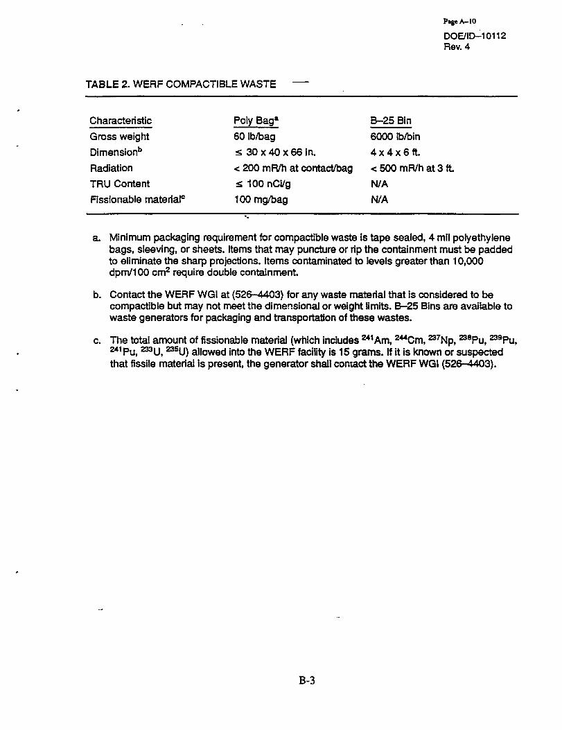
TABLE 2. WERF OOMPAOTIBLE WASTE
Characteristic Poly Bag* B-25 Bin
Gross weight 60 lb/bag 6000 lb/bin
Dimension'' ^ 30 x 40 x 66 in. 4 x 4 x 6 ft.
Radiation < 200 mR/h at contact/bag < 500 mR/h at 3 ft.
TRU Content :s100nOi/g N/A
Rssionable material" 100 mg/bag N/A
a. Minimum packaging requirement for compactible waste is tape sealed, 4 mil polyethylene bags, sleeving, or sheets. Items that may puncture or rip the containment must be padded to eliminate the sharp projections. Items contaminated to levels greater than 10,000 dpm/100 cm^ require double containment.
b. Contact the WERF WGI at (526-4403) for any waste material that is considered to be compactible but may not meet the dimensional or weight limits. B-25 Bins are available to waste generators for paclcaging and transportation of these wastes.
c. The total amount of fissionable material (which includes ^^^Am, 2**0m, ^^^^p^ 238p,j 239py 241 pu^ 233y 235u) allowed Into the WERF facility is 15 grams. If it is known or suspected that fissile material is present, the generator shall contact the WERF WGI (526-4403).
B-3

Page A - I I
DOE/ID-10112 Rev. 4
TABLE 3. WERF PROCESSABLE AND NONCOMPACTIBLE METALLIC WASTE*
Characteristic
Gross weight*
Dimension (nominal)
Rssionable material*'
TRU content**
Radiation*
Uner
Closures
D & D Bin**
6000 lb/bin
78 in w X 48 in h x
l U i n l
15g
~ TRU (alpha) < 0.5 nOI/g or 250 dpm/1 OOcm^
< 100 mR/h at contact
optional
supplied with bin
Wooden Box
6000 lb/box
4 X 4 X 8 ft.
15g
TRU (alpha) < 0.5 nOi/g or 250 dpm/100cm2
< 100 mR/h at contact
8-mil poly taped closed
supplied with box
a. Only stainless or carbon steels, aluminum, copper or copper alloys stripped of Insulation and other foreign materials, unless otherwise approved by the WERF WGI, are acceptable and may be shipped in the same container. Ail pipes and vessels interiors shall be free of liquids and/or hazardous and toxic materials. Loose sur^ce contamination shall be contained by covering over pipe ends with tape or poly, or wrapping the items in polyethylene. Metallic materials tinat cannot be readily shipped in the standard containers, may be acceptable on a case-by-case basis depending on the WERF WGIs evaluation.
b. D&D Bins may be obtained from the WERF for use by INEL waste generators as needed.
c. Gross weight limits are based on container designs.
d. The total amount of fissionable material (which includes ^^Am, 2**0m, ^^Np, ^spu, 239pu 241 pu, 233U, 235u) allowed in the WERF facility is 15 grams. If it is known or suspected that fissile material is present, the generator should contact the WERF WGI (6-4403).
e. Waste with hot spots greater than 100 mR/h may be processable at WERF if approved by tiie WERF WGI.
f. Liner is optional for the D&D bin, cover the bottom with blotter paper prior to loading. For tiie 4 X 4 X 8 ft. wooden boxes, continuous 8-mil yellow poly liners tape sealed Is required.
g. Wooden Boxes: Place and nail Hd using 8-penney cement coated nails or 1-1/2" staples on 12" centers.
B-4

PageA^lS
DOE/ID-10112 Rev. 4
TABLE 4. RWMC CONTACT HANDLED LOW-LEVEL WASTE
Characteristic
Gross Weight
Dimension
Radiation limit
TRU contentJ
Fissionable^'S material
Liner
Lid gasket
Banding
Characteristic
Gros? Weight
Dimensions
Radiation limit
TRU content'
Rssionabie*' material
Liner
Ud gasket
Closure
DOT Steel Drum
DOT limit or 20-lb/gal''
5-gal minimum
55-gal preferred
71-gal maximum
<500mR/hat3f t
^ 10 nCi/g for disposal and ^ 100 nCi/g for storage -
< 200 g/55 gal dnjm. < 5g/ft? for all other daims
Double 4-mil continuous yellow poly film sealed with tape**-'
Secured*'*'
N/A
B-25 Box
6000 lb
4 X 4 X 6 ft.
< 500 mR/h at 3 ft
^ 10 nCI/g for disposal and ^ 1 0 0 nCi/g for storage
5g/ft3
N/A
Mfg. installed
Seal lock clips
INEL Wooden Boxes*
60001b
4 x 4 x 4 f t
2 x 4 x 8 f t
4 x 4 x 8 f t
< 500 mR/h at 3 ft
^ 10 nCi/g for disposal and s 100 nCI/g for storage
< 177 g/m^ (5 g/ft^) of waste volumetric average and < 350 g/box
Double 4-mll continuous yellow poly film sealed with tape" -'
Secured*-'
O.S-in. steel, 4 each
M-lll Bin
80001b
4 x 5 x 6 f L
< 500 mR/h at 3 ft
£ 10 nCl/g for disposal and s 100 nCl/g for storage
s 60 g U-235
Double 4-mil continuous yellow poly film sealed with tape'
1-in. wide by 0.44-in thick.
Watertight"
a. INEL wooden waste boxes may qualify as strong tight container if used correctly.
Maximum loaded gross weight, uniformly distributed, for the INEL boxes is 6000 lb. These boxes shall be banded with 1/2-4n. steel banding material. As a minimum, use four bands equally spaced, one-third the distance from the top and bottom and one-third the length of the box from each end. These boxes are available from the EG&G Idaho Storeroom. The generator must provide sufficient blocking to keep heavy items in place and to distribute
B-5

PageA-16
DOE/iD-10112 Rev. 4
the load uniformly within the container. To help ensure box integrity is maintained, during transit a minimum of 90% of each box skid shall be in contact with the truck/trailer deck.
b. DOT limit for a 55-gallon 7A container is 800 pounds, and a 71-gallon square dmm is 1300 pounds. The 20-pounds per gallon limit, for the 55 and 71 gallon drums, qualifies for* a DOT strong tight container. This limit is permitted because the drums passed the DOT 7A drop test at that loaded weight
c. The fissionable material limits are based on low-density and volumetric-average assumptions. Low-density fissile waste is waste consisting of materials such as paper, polyethylene wrap, tape, glass, rags, blotting paper, scrap metal, piping, etc., contaminated with small amounts of fissile material. Volumetric average Is defined as concentrations obtained by dividing the total fis'sile material content of a container by its volume.
d. A damaged liner shall be repaired or replaced. ~
e. All container lids shall be secured to ensure contamination control through all phases of handling and transportation.
f. Wrapping of individual waste items in 8-mil yellow polyethylene, or equivalent. A double 4-mil liner is an alternative for the 8-mil liner.
g. This limit is for cylindrical drums only. The square configured drums are limited to 5 g/ft or less. Container specific criticaiity analysis studies are required for increased fissile loading.
h. Closure ring bolts shall be torqued to a minimum of 40 ft-lb.
1. Apply elastomeric constnjction adhesive (B. F. Goodrich PL- tt)0 or RWMC-approved equivalent) in a continuous bead of 1/4 in. minimum diameter ail around the lid surface. Place and nail lid using 8-penny cement-coated nails or 1-1/2 In. staples on 12-in. centers. Remove excess adhesive from outside surface of the box.
j . Waste contaminated with transuranic isotopes <100 nCI/g but >10 nCi/g are excluded from disposal at the RWMC. RWMC "RADIOACTIVE WASTE MANAGEMENT COMPLEX PERFORMANCE ASSESSMENT", EGG-WM-8773,1990*, radiological perfonnance calculations, recorded in Engineering Design Rles (EDFs) RWMC-484 "Summary Report: Waste Concentration Umits for RWMC" and RWMC-485 "Detail Report: Waste Concentration Limits for RWMC", indicate that disposal of this waste presents a hazard to future inadvertent intruders.
Solid contact-handled LLW waste containing less than or equal to 100 nCl/g of TRU contaminants and greater than 10 nCi/g of TRU contaminants shall be packaged per the INEL Transuranic Waste Acceptance Criteria, DOE/II>-10074^, and shipped to the RWMC for interim storage.
k. B-25 compactor box may qualify as a strong tight container.
1. Neoprene gasket (1-3/4 in.-wide x 1/4 in.-<hick) bonded to the lid and body using nonhardening gasket sealer. Securing the lid with 5/16-in. hex head screws In combination with 16-gauge galvanized washers with a 1/8-in. thick neoprene material, heat and pressure bonded to the under side of the v^^sher.
B-6

P»geA-17
DOE/iD-10112 Rev. 4
TABLE 5. RWMC REMOTE-HANDLED LOW-LEVEL WASTE
Characteristic HFEF-5 Canister Other
Gross weight
Radiation limit
TRU content*
Rssionable material'
Ud gasket
10001b.
> 500 mR/h at 3 ft.
£ 10 nCI/g for disposal and :£ 100 nCi/g for storage
<150g»'
Seal welded or bolted with Viton seal
Limited to specific package
> 500 mR/h at 3 ft.
^ 1 0 nCi/g for disposal and £ 100 nCi/g for storage
See container limits as listed in Table 4.
Watertight
Characteristic
Gross weight
Dimension
Radiation limit
TRU content*
Rssionable material''
Closure
55-Ton Insert
12,0001b
4 ft dia X 8 ft high
> 500 mR/h at 3 ft
£ 10 nCi/g for disposal and ^ 1 0 0 nCi/g for storage <5g/ft3
Bolted-With gasket
TRA Resin Tank
20,000 lb
6 ft dia X 7 ft high
> 500 mR/h at 3 ft.
£ 10 nCi/g for disposal and ^ 100 nCi/g for storage
< 177 g/m^ and <300 g/tank
Spring loaded and gasketed
a. The fissionable material limits are based on low density and volumetric average assumptions. Low density fissile waste is waste consisting of materials such as paper, polyethylene wrap, tape, glass, rags, blotting paper, scrap metal, piping, etc., contaminated with small amounts of fissile material. Volumetric average is defined as concentrations obtained by dividing the total fissile material content of a container by its volume.
b. Rssionable material limit for soil vaults at the RWMC is 300 g. RWMC Soil Vault Criticaiity Safety Evaluation, Report Number SD-C-80-005, June 1980.*
c. Waste contaminated with transuranic isotopes <100 nCi/g but >10 nCi/g are excluded from disposal at the RWMC. RWMC'RADIOACTIVE WASTE MANAGEMENT COMPLEX PERFORMANCE ASSESSMENT", EGG-WM-8773,1990, radiological performance calculations, recorded in Engineering Design Rles (EDFs) RWMC-484"Summary Report: Waste Concentration Umits for RWMC" and RWMC-485"Detail Report: Waste Concentration Umits for RWMC", indicate tiiat disposal of this waste presents a hazard to future inadvertent intruders.
Solid remote-handled LLW waste containing less than or equal to 100 nCi/g of TRU contaminants and greater than 10 nCI/g of TRU contaminants shall be packaged per the INEL Transuranic Waste Acceptance Criteria, DOE/ID-10074^, and shipped to the RWMC for interim storage.
B-7