Icom IC-F50_F60 Instruction Manual
25
INSTRUCTION MANUAL This device complies with Part 15 of the FCC rules. Operation is subject to the condition that this device does not cause harmful interference. UHF TRANSCEIVER iF60 VHF TRANSCEIVER iF50
-
Upload
yayok-s-anggoro -
Category
Documents
-
view
248 -
download
0
Transcript of Icom IC-F50_F60 Instruction Manual

8/8/2019 Icom IC-F50_F60 Instruction Manual
http://slidepdf.com/reader/full/icom-ic-f50f60-instruction-manual 1/29
INSTRUCTION MANUAL
This device complies with Part 15 ofthe FCC rules. Operation is subject tothe condition that this device does notcause harmful interference.
UHF TRANSCEIVER
iF60
VHF TRANSCEIVER
iF50
8/8/2019 Icom IC-F50_F60 Instruction Manual
http://slidepdf.com/reader/full/icom-ic-f50f60-instruction-manual 2/29

8/8/2019 Icom IC-F50_F60 Instruction Manual
http://slidepdf.com/reader/full/icom-ic-f50f60-instruction-manual 3/29
iii
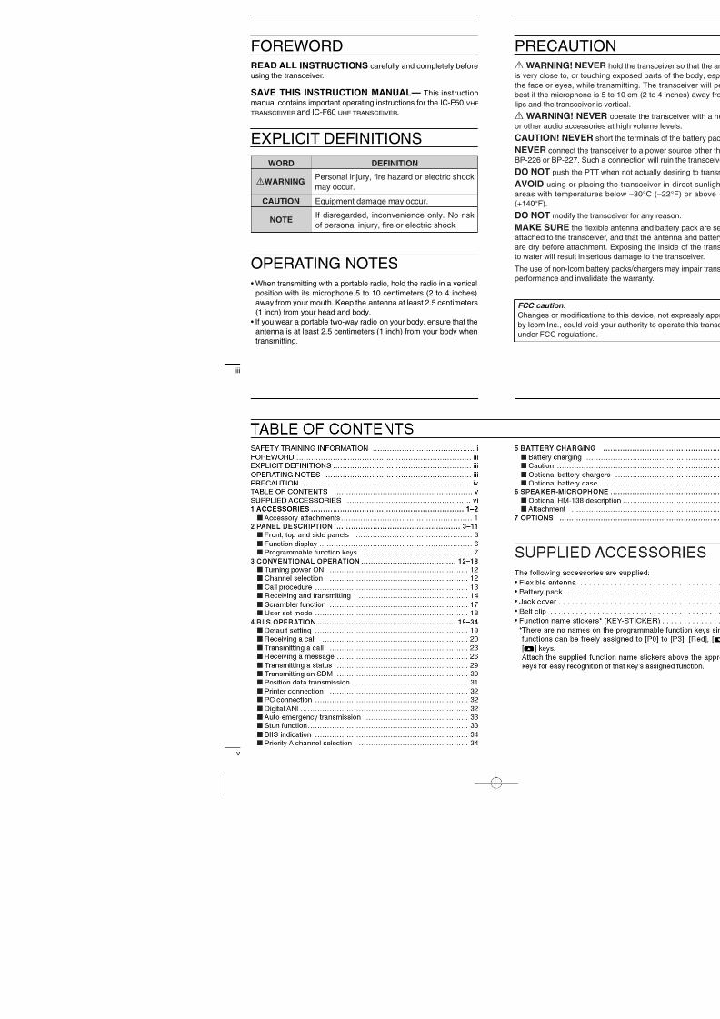
FOREWORDREAD ALL INSTRUCTIONS carefully and completely beforeusing the transceiver.
SAVE THIS INSTRUCTION MANUAL— This instructionmanual contains important operating instructions for the IC-F50 VHF
TRANSCEIVER and IC-F60 UHF TRANSCEIVER .
EXPLICIT DEFINITIONS
OPERATING NOTES• When transmitting with a portable radio, hold the radio in a vertical
position with its microphone 5 to 10 centimeters (2 to 4 inches)away from your mouth. Keep the antenna at least 2.5 centimeters(1 inch) from your head and body.
• If you wear a portable two-way radio on your body, ensure that theantenna is at least 2.5 centimeters (1 inch) from your body whentransmitting.
WORD DEFINITION
R WARNING Personal injury, fire hazard or electric shockmay occur.
NOTE If disregarded, inconvenience only. No riskof personal injury, fire or electric shock.
CAUTION Equipment damage may occur.
8/8/2019 Icom IC-F50_F60 Instruction Manual
http://slidepdf.com/reader/full/icom-ic-f50f60-instruction-manual 4/29

8/8/2019 Icom IC-F50_F60 Instruction Manual
http://slidepdf.com/reader/full/icom-ic-f50f60-instruction-manual 5/291
1 ACCESSORIESI Accessory attachmentsD Flexible antennaConnect the supplied exible antennato the antenna connector.
CAUTION!• NEVER HOLD by the antenna
when carrying the transceiver.• Transmitting without an antenna
may damage the transceiver.
ï Battery pack To attach the battery pack: Slide the battery pack on the back of the transceiver in the direc-tion of the arrow ( q ), then lock it with the battery release button.• Slide the battery pack until the battery release button makes a ‘click’
sound.
To release the battery pack: Push the battery release button in the direction of the arrow ( w ) asshown below. The battery pack is then released.
q
w
Battery pack
Battery release button
NEVER release or at-tach the battery packwhen the transceiveris wet or soiled. Thismay result water ordust getting into thetransceiver/batterypack and may resultin the transceiverbeing damaged.
8/8/2019 Icom IC-F50_F60 Instruction Manual
http://slidepdf.com/reader/full/icom-ic-f50f60-instruction-manual 6/293
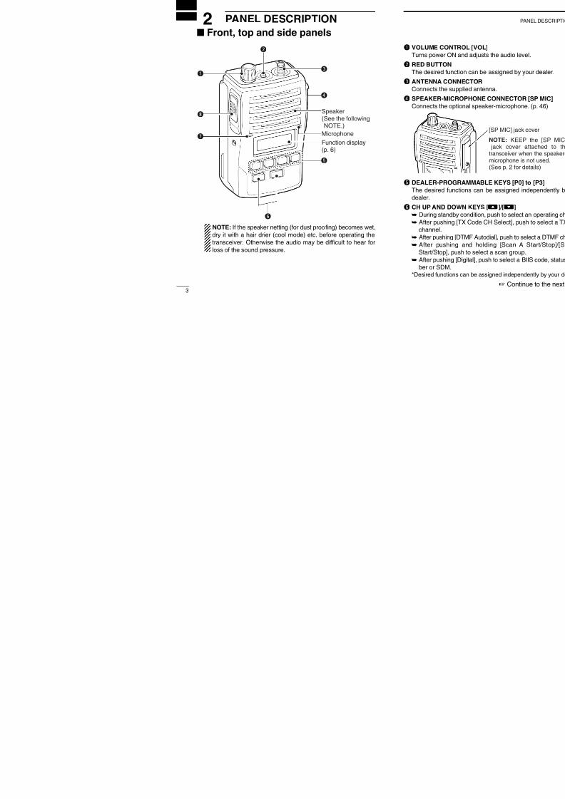
2 PANEL DESCRIPTIONI Front, top and side panels
NOTE: If the speaker netting (for dust proo ng) becomes wet,dry it with a hair drier (cool mode) etc. before operating thetransceiver. Otherwise the audio may be dif cult to hear forloss of the sound pressure.
q
w
e
r
t
y
i
u MicrophoneFunction display(p. 6)
Speaker(See the followingNOTE.)
8/8/2019 Icom IC-F50_F60 Instruction Manual
http://slidepdf.com/reader/full/icom-ic-f50f60-instruction-manual 7/29
5
2 PANEL DESCRIPTION
I Front, top and side panels (Continued)
u TRANSMIT/BUSY INDICATOR
Lights red while transmitting; lights green while receiving a sig-nal, or when the squelch is open.i PTT SWITCH [PTT]
➥ Push and hold to transmit; release to receive.
8/8/2019 Icom IC-F50_F60 Instruction Manual
http://slidepdf.com/reader/full/icom-ic-f50f60-instruction-manual 8/29
7
2 PANEL DESCRIPTION
I Programmable function keysThe following functions can be assigned to [P0] , [P1] , [P2] , [P3] ,[Red] , [ ] and [ ] programmable function keys.Consult your Icom dealer or system operator for details concerningyour transceivers programming.If the programmable function names are bracketed in the followingexplanations, the speci c switch used to activate the function de-pends on programming.
CH UP AND DOWN KEYS • Select an operating channel.• Select a transmit code channel after pushing the [TX Code CH
Select] keys.• Select a DTMF channel after pushing the [DTMF Autodial] key.• Select a scan group after pushing and holding the [Scan A
Start/Stop]/[Scan B Start/Stop] keys.• Select a BIIS code, status number or SDM after pushing the
[Digital] key.
BANK SELECT KEY Push this key, then push [CH Up] or [CH Down] to select the de-sired bank.
SCAN START/STOP KEYS ➥ Push this key to start scanning; and push again to stop.➥ Push and hold this key to indicate the scan group, then select
the desired scan group using [CH Up]/[CH Down].
SCAN TAG KEY Adds or deletes the selected channel to the scan group.

8/8/2019 Icom IC-F50_F60 Instruction Manual
http://slidepdf.com/reader/full/icom-ic-f50f60-instruction-manual 9/29

8/8/2019 Icom IC-F50_F60 Instruction Manual
http://slidepdf.com/reader/full/icom-ic-f50f60-instruction-manual 10/29
11
2 PANEL DESCRIPTION
VOICE SCRAMBLER FUNCTION Push to toggle the voice scrambler function ON and OFF.
COMPANDER KEY Push to toggle the compander function ON and OFF.The compander function reduces noise components from the trans-mitting audio to provide clear communication.
USER SET MODE KEY ➥ Push and hold to enter user set mode.
• During user set mode, push this key to select an item, and push[CH Up]/[CH Down] to change the value or condition.
➥ Push and hold this key again to exit user set mode.• User set mode is also available via the ‘Power ON function ’. Please
refer to p. 18 also.
DIGITAL KEY (BIIS operation only)
➥ Push to select the call ID list, transmit message and standbycondition. Toggles between queue channel and received mes-sage record indication after queue channel is selected.
➥ Push and hold to select queue channel indication.
STATUS UP/DOWN KEYS (BIIS operation only)➥ While in the standby condition, push to display the transmit sta-
tus indication and select a status number.➥ When a received SDM is displayed, push to cancel the automatic
scroll and scroll the message manually.➥ When an SDM that contains more than 8 characters is displayed,
push to scroll the message manually.
8/8/2019 Icom IC-F50_F60 Instruction Manual
http://slidepdf.com/reader/full/icom-ic-f50f60-instruction-manual 11/29
13
3 CONVENTIONAL OPERATION
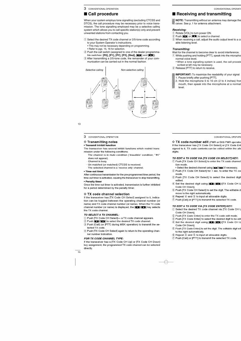
I Call procedureWhen your system employs tone signalling (excluding CTCSS andDTCS), the call procedure may be necessary prior to voice trans-mission. The tone signalling employed may be a selective callingsystem which allows you to call speci c station(s) only and preventunwanted stations from contacting you.
q Select the desired TX code channel or 2/5-tone code accordingto your System Operator ’s instructions.• This may not be necessary depending on programming.• Refer to pgs. 15, 16 for selection.
w Push the call switch (assigned to one of the dealer programma-ble switches: [P0], [P1], [P2], [P3], [Red], [ ] and [ ]).
e After transmitting a 2/5-tone code, the remainder of your com-munication can be carried out in the normal fashion.
Selective calling Non-selective calling

8/8/2019 Icom IC-F50_F60 Instruction Manual
http://slidepdf.com/reader/full/icom-ic-f50f60-instruction-manual 12/29

8/8/2019 Icom IC-F50_F60 Instruction Manual
http://slidepdf.com/reader/full/icom-ic-f50f60-instruction-manual 13/29
17
3 CONVENTIONAL OPERATION
D DTMF transmissionIf the transceiver has [DTMF Autodial] assigned to it, the automaticDTMF transmission function is available. Up to 8 DTMF channelsare available.
TO SELECT A TX CODE: q Push [DTMF Autodial] — a DTMF channel appears.w Push [ ]/[ ] to select the desired DTMF channel.e Push [DTMF Autodial] to transmit the DTMF code in the selected
DTMF channel.
I Scrambler functionThe voice scrambler function provides private communication be-tween stations. The frequency inversion type is equipped to all ver-sions, and some versions have the Rolling or Non-rolling typeinstalled.
q Push [Scrambler] to turn the scrambler function ON.w “ ”appears.e Push [Scrambler] again to turn the scrambler function OFF.

8/8/2019 Icom IC-F50_F60 Instruction Manual
http://slidepdf.com/reader/full/icom-ic-f50f60-instruction-manual 14/29
19
4 BIIS OPERATIONI Default settingThe following functions are assigned to each programmable switchas the default. Ask your dealer for details.
[P0]; Call : Push to transmit a 5-tone/BIIS call when theselected channel is a 5-tone or MSK channel,respectively.
[P1]; Digital : Push to select the call list ID/transmit mes-sage, or to display the receive message
record for selection.[P3]; Moni(Audi) : Push this key after the communication to
send a “clear down ” signal during MSK chan-nel operation.
[ ]/[ ]; CH Down/Up: While in the standby condition, selects the
operating channel.
After pushing [Digital] or [TX Code CH Se-lect], selects call list or TX code channel, re-spectively.
[P2]/[Red]; Null : No function is assigned.

8/8/2019 Icom IC-F50_F60 Instruction Manual
http://slidepdf.com/reader/full/icom-ic-f50f60-instruction-manual 15/29
21
4 BIIS OPERATION
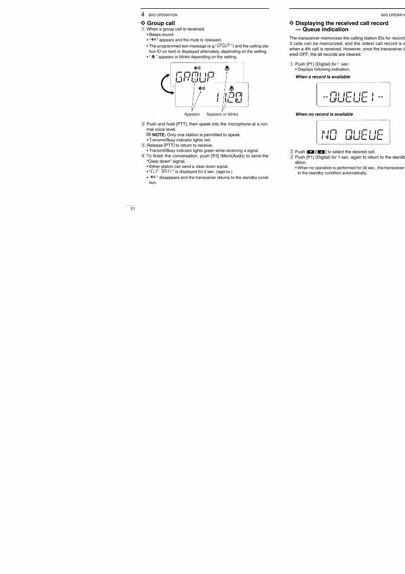
D Group callq When a group call is received;
• Beeps sound.• “ ”appears and the mute is released.• The programmed text message (e.g. “ ”) and the calling sta-
tion ID (or text) is displayed alternately, depending on the setting.• “ ”appears or blinks depending on the setting.
w Push and hold [PTT], then speak into the microphone at a nor-mal voice level.
NOTE: Only one station is permitted to speak.• Transmit/Busy indicator lights red.
e Release [PTT] to return to receive.
• Transmit/Busy indicator lights green while receiving a signal.r To finish the conversation, push [P3] (Moni(Audi)) to send the“Clear down ” signal.• Either station can send a clear down signal.• “ ” is displayed for 2 sec. (approx.)• “ ”disappears and the transceiver returns to the standby condi-
tion.
Appears or blinksAppears

8/8/2019 Icom IC-F50_F60 Instruction Manual
http://slidepdf.com/reader/full/icom-ic-f50f60-instruction-manual 16/29
23
4 BIIS OPERATION
I Transmitting a callTotal of a 3 ways for code selection are available —selecting the call
code from memory, entering the call code from the keypad and call-ing back from the queue channel record.
D Using call memoryq While in the standby condition, push [P1] (Digital) to enter the
call code memory channel selection mode.
w Push [ ]/[ ] to select the desired call code.e Push [P0] (Call) or [PTT]* to call.
*PTT call can be made only when PTT call capability is permitted.
NOTE: When no answer back is received, the transceiver re-peats the call 3 times (default) automatically, and “ ” isdisplayed during each call. However, an error beep soundsand “ ” is displayed when no answer back is received
after the calls.r Push [PTT] to transmit; release to receive.t Push [P3] (Moni(Audi)) to send the “Clear down ” signal.
Call code text is displayed.

8/8/2019 Icom IC-F50_F60 Instruction Manual
http://slidepdf.com/reader/full/icom-ic-f50f60-instruction-manual 17/29
25
4 BIIS OPERATION
D Direct code entryq While in the standby condition, push [TX Code Enter] to enter
the TX code edit mode.• Editable code digit blinks.
w Push [TX Code Enter] to select the desired digit to be edited.• Editable digit differs according to the setting.
e Set the desired digit using [ ]/[ ]/[TX Code CH Up]/[TXCode CH Down].
r Push [TX Code Enter] to set the digit. The editable digit will moveto the right automatically.
t Repeat e and r to input all allowable digits.y Push [P0] (Call) or [PTT]* to call.
*PTT call can be made only when PTT call capability is permitted.
NOTE: When no answer back is received, the transceiver re-peats the call 3 times (default) automatically, and “ ” isdisplayed during each call. However, an error beep soundsand “ ” is displayed when no answer back is received
after the calls.u Push [PTT] to transmit; release to receive.i Push [P3] (Moni(Audi)) to send the “Clear down ” signal.
For your information When the “UpDate ” setting for the call code is enabled, the set codeis overwritten into the call code memory.

8/8/2019 Icom IC-F50_F60 Instruction Manual
http://slidepdf.com/reader/full/icom-ic-f50f60-instruction-manual 18/29
27
4 BIIS OPERATION
D Receiving an SDMq When an SDM is received;
• Beeps sound.
• The calling station ID (or text) and the SDM is displayed alternately,depending on the setting.
w When the received SDM includes more than 8 characters, themessage scrolls automatically, when the automatic scroll func-
tion is activated.• Push [Status Up]/[Status Down] to scroll the message manually.e Push [P3] (Moni(Audi)) to return to the standby condition.

8/8/2019 Icom IC-F50_F60 Instruction Manual
http://slidepdf.com/reader/full/icom-ic-f50f60-instruction-manual 19/29
29
4 BIIS OPERATION
I Transmitting a statusD GeneralThe status message can be selected with the programmed text,and the message text is also displayed on the function display ofthe called station.Up to 24 status types (1 to 24) are available, and the status mes-sages 22 and 24 have designated meanings.
Status 22: Emergency*Status 24: GPS request*The status 22 can also be used as a normal status message by dis-abling the designated meaning. However, the status 24 is xed.
The status call can be sent with both individual and group calls.
D Transmitting a statusq While in the standby condition, push [P1] (Digital), then push
[ ]/[ ] to select the desired station/group code.w Push [P1] (Digital) again, then push [ ]/[ ] to select the de-
sired status message.
Or, you can select the desired status message using [StatusUp]/[Status Down] key directly.
e Push [P0] (Call) or [PTT]* to transmit the status message to theselected station/group.
*PTT call can be made only when PTT call capability is permitted.• 2 beeps will sound and the transceiver returns to the standby con-dition automatically when the transmission is successful.
Status message is displayed.

8/8/2019 Icom IC-F50_F60 Instruction Manual
http://slidepdf.com/reader/full/icom-ic-f50f60-instruction-manual 20/29
31
4 BIIS OPERATION
I Position data transmissionWhen the optional OPC-966 INTERFACE CABLE and a GPS receiver
is connected to the transceiver, the position (longitude and latitude)data can be transmitted automatically.Ask your dealer or system operator for connection details.
The position data is transmitted when;• Status 24 message is received
*When the status 24 message, GPS request, is received.• Fully automatic
When automatic position transmission is enabled, send the po-sition data according to ‘Time Marker ’ and ‘Interval Timer ’ set-tings.
• PTT is releasedWhen ‘Send with Logoff ’ is enabled.- Set the “Log-In/Off ” item as “L-OFF ”.
• After sending a status messageWhen ‘Send with Status ’ is enabled.
• After sending an SDMWhen ‘Send with SDM ’ is enabled.
• After sending status 22 (Emergency)When ‘Send with Emergency ’ is enabled.

8/8/2019 Icom IC-F50_F60 Instruction Manual
http://slidepdf.com/reader/full/icom-ic-f50f60-instruction-manual 21/29
33
4 BIIS OPERATION
I Auto emergency transmissionWhen [Emergency Single (Silent)] or [Emergency Repeat (Silent)] is
pushed, an emergency signal is automatically transmitted for thespeci ed time period.
The status 22 (Emergency) is sent to the selected ID station, andthe position data is transmitted after the emergency signal when aGPS receiver is connected to the transceiver.
The emergency transmission is performed on the emergency chan-
nel, however, when no emergency channel is speci ed, the signal istransmitted on the previously selected channel.
There is no change in the function display or beep emission duringautomatic emergency transmission.
I Stun functionWhen the speci ed ID, set as a killer ID, is received, the stun func-tion is activated.
When the killer ID is received, the transceiver switches to the pass-code required condition. Entering of the passcode via the keypad isnecessary to operate the transceiver again in this case.
5

8/8/2019 Icom IC-F50_F60 Instruction Manual
http://slidepdf.com/reader/full/icom-ic-f50f60-instruction-manual 22/29
35
5 BATTERY CHARGINGI Battery chargingPrior to using the transceiver for the rst time, the battery pack must
be fully charged for optimum life and operation.CAUTION: To avoid damage to the transceiver, turn it OFF whilecharging.
• Recommended temperature range for charging:+10 °C to +40 °C (+50 °F to +104 °F)- The Li-Ion battery functions within –20 °C to +60 °C ( –4°F to
+140 °F)• Use the specified chargers (BC-152, BC-119N and BC-121N).
NEVER use another manufacturer ’s charger.• Use the optional AC adapter (BC-147A/E) for the BC-152.• NEVER use another manufacturer ’s AC adapter.
Recommendation: Charge the supplied battery pack for a maximum of up to10 hours. Li-Ion batteries are different from Ni-Cd batteries in thatit is not necessary to completely charge and discharge them toprolong the battery life. Therefore, charging the battery in inter-vals, and not for extended periods is recommended.
8/8/2019 Icom IC-F50_F60 Instruction Manual
http://slidepdf.com/reader/full/icom-ic-f50f60-instruction-manual 23/29
37
5 BATTERY CHARGING
I Optional battery chargersï Regular charging with the BC-152q Attach the BC-152 to a at surface, such as a desk, if desired.w Connect the AC adapter (BC-147A/E*) as shown below.
*Depending on version.e Insert the battery pack with/without the transceiver into the
charger.• The charge indicator lights green.
r Charge the battery pack approx. 9 –10 hours, depending on the
remaining power condition.
Charge indica-
tor lights greenwhen BP-227(wi th /wi thoutIC-F50/F60) isinserted.
AC adapterBC-152
BP-227IC-F50/F60
Supplied screws
Ensure sides of thebattery pack are cor-rectly aligned withthe charger groves.

8/8/2019 Icom IC-F50_F60 Instruction Manual
http://slidepdf.com/reader/full/icom-ic-f50f60-instruction-manual 24/29
39
5 BATTERY CHARGING
ï AD-100 installationq Install the AD-100 desktop charger adapter into the holder space
of the BC-119N/121N.
Desktop charger adapter
Connectors
Plugs

8/8/2019 Icom IC-F50_F60 Instruction Manual
http://slidepdf.com/reader/full/icom-ic-f50f60-instruction-manual 25/29
41
5 BATTERY CHARGING
D Rapid charging with the BC-119N+AD-100The optional BC-119N provides rapid charging of optional Li-Ionbattery packs.
The following are additionally required:• One AD-100 (purchase separately) .• An AC adapter (may be supplied with BC-119N depending on ver-
sion) or the DC power cable (OPC-515L/CP-17L).
AC adapter(Not supplied withsome versions.)
AD-100 chargeradapter is instal-led in BC-119N.
BP-227
IC-F50/F60
Optional OPC-515L (for 13.8 Vpower source) or CP-17L (for12 V cigarette lighter socket)can be used instead of the ACadapter.
5

8/8/2019 Icom IC-F50_F60 Instruction Manual
http://slidepdf.com/reader/full/icom-ic-f50f60-instruction-manual 26/29
43
5 BATTERY CHARGING
I Optional battery caseWhen using the optional battery case attached to the transceiver,
install 5 × AA (R6) size alkaline batteries as illustrated at right. TheBP-226 meets JIS waterproof speci cation grade 4.
q Hook your nger under the latch, and open the cover in the direc-tion of the arrow ( q ). (Fig.1)
w Then, install 5 × AA (R6) size alkaline batteries. (Fig.2)• Install the alkaline batteries only.• Be sure to observe the correct polarity.• Do not pin the ribbon under the batteries.
e Close the cover by tting in the direction of the arrow ( w ) rst,then check the latch is in place ( e ). (Fig.1)• Be sure the gasket and the ribbon are set correctly, and do not pro-
trude from the battery case. (Fig.3)
CAUTION:• When installing batteries, make sure they are all the same
brand, type and capacity. Also, do not mix new and old batter-ies together.
• Keep battery contacts clean. It ’s a good idea to clean batteryterminals once a week.
6 SPEAKER MICROPHONE

8/8/2019 Icom IC-F50_F60 Instruction Manual
http://slidepdf.com/reader/full/icom-ic-f50f60-instruction-manual 27/29
45
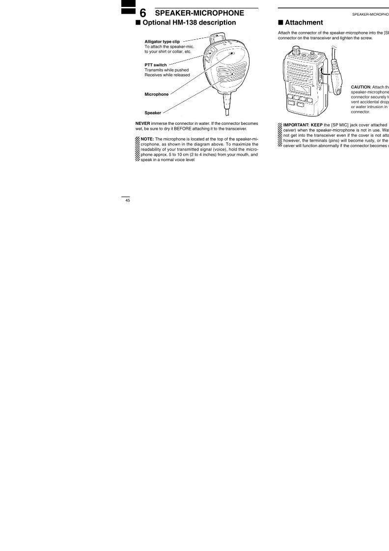
6 SPEAKER-MICROPHONEI Optional HM-138 description
NEVER immerse the connector in water. If the connector becomeswet, be sure to dry it BEFORE attaching it to the transceiver.
NOTE: The microphone is located at the top of the speaker-mi-crophone, as shown in the diagram above. To maximize thereadability of your transmitted signal (voice), hold the micro-phone approx. 5 to 10 cm (2 to 4 inches) from your mouth, andspeak in a normal voice level.
Alligator type clipTo attach the speaker-mic.to your shirt or collar, etc.
PTT switchTransmits while pushed
Receives while released
Microphone
Speaker
7 OPTIONS

8/8/2019 Icom IC-F50_F60 Instruction Manual
http://slidepdf.com/reader/full/icom-ic-f50f60-instruction-manual 28/29
47
7 OPTIONS• BP-226 BATTERY CASE
Battery case for 5 × AA (R6) alkaline cells.
• BP-227 L i-Ion BATTERY PACK
7.2 V/1700 mAh Li-Ion battery pack. The same as supplied withthe transceiver. BP-227 must be charged with the optional BC-152or the BC-119N/121N.
BP-226 BP-227
• BC-152 DESKTOP CHARGER + BC-147A/E AC ADAPTER
Used for regular charging of the batterypack. The AC adapter, BC-147A/E,must be purchased separately.Charging time: approx. 9 –10 hours
• BC-119N DESKTOP CHARGER + AD-100 CHARGER ADAPTER
+ BC-145 AC ADAPTER
For rapid charging of battery packs. AnAC adapter is not supplied with someversions.Charging time: approx. 2 to 2.5 hours

8/8/2019 Icom IC-F50_F60 Instruction Manual
http://slidepdf.com/reader/full/icom-ic-f50f60-instruction-manual 29/29
1-1-32 Kamiminami, Hirano-ku, Osaka 547-0003, Japan
A-6294H-1EXPrinted in Japan
© 2003 Icom Inc.