Icom IC-7600 manual (PDF) - アイコム株式会社 ホー … IC-7600 manual (PDF) -...
180
INSTRUCTION MANUAL HF/50 MHz TRANSCEIVER i7600
-
Upload
duongthuan -
Category
Documents
-
view
266 -
download
0
Transcript of Icom IC-7600 manual (PDF) - アイコム株式会社 ホー … IC-7600 manual (PDF) -...

INSTRUCTION MANUAL
HF/50 MHz TRANSCEIVER
i7600
FOREWORD
Thank you for makng the IC-7600 your rado of choce. We hope you agree wth Icom’s phlosophy of “technology frst.” Many hours of research and devel-opment went nto the desgn of your IC-7600.
FEATURES Ultimate receiver performance: third-order inter-
cept (IP3) of +30 dBm (HF bands only) Built-in Baudot RTTY and PSK modulator/demodu-
lator and direct PC keyboard connection capability for RTTY and PSK operations without a PC
High resolution spectrum scope— center frequency and fixed frequency modes, plus mini-scope dis-plays
USB connectors on front and rear panels Large LCD with LED backlight
IMPORTANT
READ THIS INSTRUCTION MANUAL CAREFULLY before attemptng to operate the transcever.
SAVE THIS INSTRUCTION MANUAL. Ths manual contans mportant safety and operatng nstructons for the IC-7600.
EXPLICIT DEFINITIONS
WORD DEFINITION
RDANGERPersonal death, serous njury or an exploson may occur.
RWARNINGPersonal njury, fre hazard or electrc shock may occur.
CAUTION Equpment damage may occur.
NOTEIf dsregarded, nconvenence only. No rsk of personal njury, fire or electrc shock.
Spurous sgnals may be receved near the followng frequences. These are made n the nternal crcut and does not ndcate a transcever malfuncton.10.4923MHz, 24.576MHz
SUPPLIED ACCESSORIES
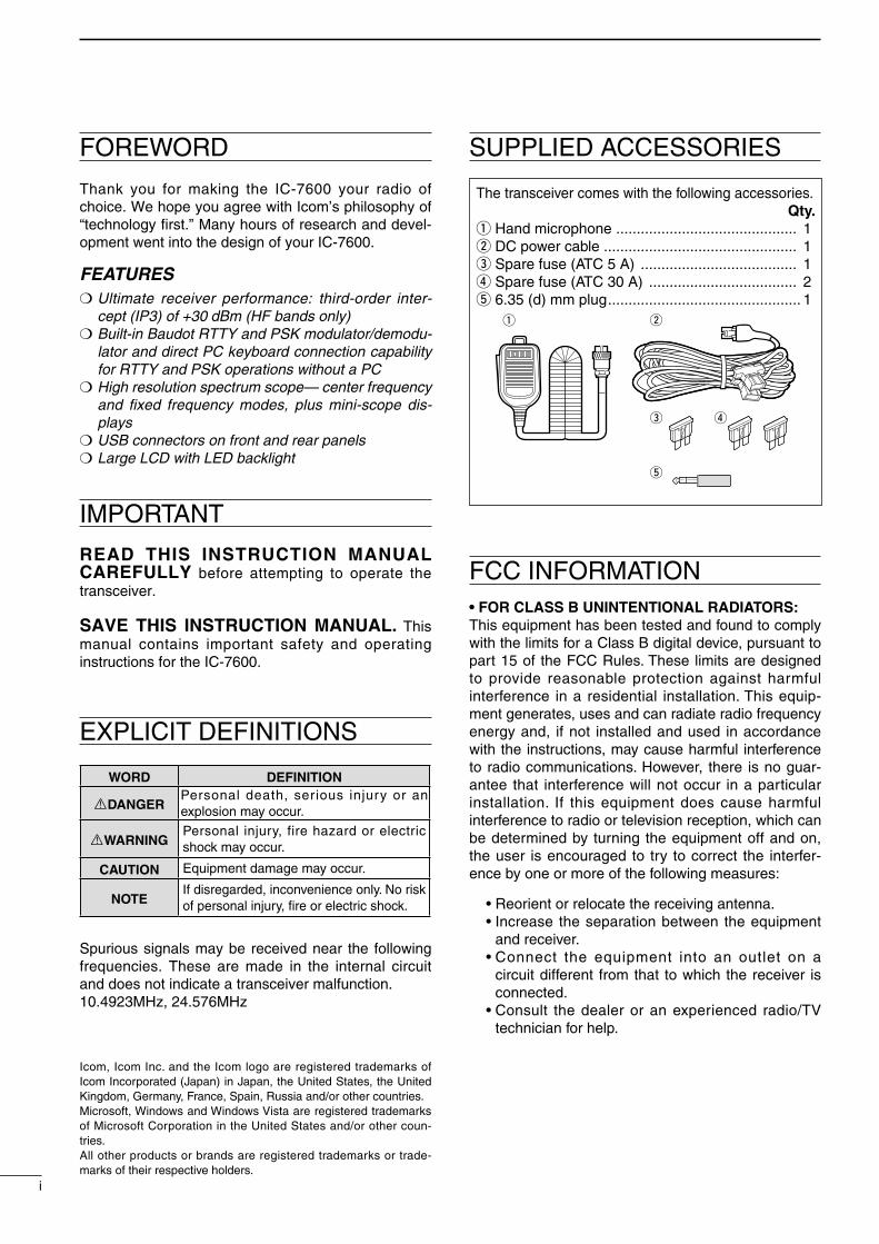
The transcever comes wth the followng accessores.Qty.
qHand mcrophone ............................................ 1wDC power cable ............................................... 1eSpare fuse (ATC 5 A) ...................................... 1rSpare fuse (ATC 30 A) .................................... 2t 6.35 (d) mm plug ............................................... 1
q
e
t
w
r
FCC INFORMATION• FOR CLASS B UNINTENTIONAL RADIATORS:Ths equpment has been tested and found to comply wth the lmts for a Class B dgtal devce, pursuant to part 15 of the FCC Rules. These lmts are desgned to provde reasonable protecton aganst harmful nterference n a resdental nstallaton. Ths equp-ment generates, uses and can radate rado frequency energy and, f not nstalled and used n accordance wth the nstructons, may cause harmful nterference to rado communcatons. However, there s no guar-antee that nterference wll not occur n a partcular nstallaton. If ths equpment does cause harmful nterference to rado or televson recepton, whch can be determned by turnng the equpment off and on, the user s encouraged to try to correct the nterfer-ence by one or more of the followng measures:
• Reorent or relocate the recevng antenna. • Increase the separaton between the equpment
and recever. • Connect the equpment nto an outlet on a
crcut dfferent from that to whch the recever s connected.
• Consult the dealer or an experenced rado/TV techncan for help.
Icom, Icom Inc. and the Icom logo are regstered trademarks of Icom Incorporated (Japan) n Japan, the Unted States, the Unted Kngdom, Germany, France, Span, Russa and/or other countres.Mcrosoft, Wndows and Wndows Vsta are regstered trademarks of Mcrosoft Corporaton n the Unted States and/or other coun-tres.All other products or brands are regstered trademarks or trade-marks of ther respectve holders.

PRECAUTIONS
R WARNING HIGH RF VOLTAGE! NEVER attach an antenna or nternal antenna connector durng transmsson. Ths may result n an electrcal shock or burn.
R WARNING! NEVER operate the transcever wth a headset or other audo accessores at hgh volume levels. Hearng experts advse aganst contnu-ous hgh volume operaton. If you experence a rngng n your ears, reduce the volume or dscontnue use.
R WARNING! Immedately turn the transcever power OFF and remove the power cable f t emts an abnormal odor, sound or smoke. Contact your Icom dealer or dstrbutor for advce.
CAUTION! NEVER put the transcever n any unstable place (such as on a slanted surface or vbrated place). Ths may cause njury and/or damage to the transcever.
CAUTION! NEVER change the nternal settngs of the transcever. Ths may reduce transcever perfor-mance and/or damage to the transcever.
In partcular, ncorrect settngs for transmtter crcuts, such as output power, dlng current, etc., mght damage the expensve fnal devces.
The transcever warranty does not cover any prob-lems caused by unauthorzed nternal adjustment.
CAUTION! NEVER apply AC power to the [DC13.8V] socket on the transcever rear panel. Ths could cause a fre or damage the transcever.
CAUTION! NEVER apply more than 16 V DC, such as a 24 V battery, to the [DC13.8V] socket on the transcever rear panel. Ths could cause a fre or damage the transcever.
CAUTION! NEVER let metal, wre or other objects protrude nto the transcever or nto connectors on the rear panel. Ths may result n an electrc shock.
CAUTION! NEVER block any coolng vents on the top, rear or bottom of the transcever.
CAUTION! NEVER expose the transcever to ran, snow or any lquds.
CAUTION! NEVER nstall the transcever n a place wthout adequate ventlaton. Heat dsspaton may be reduced, and the transcever may be damaged.
CAUTION! NEVER operate or touch the trans-cever wth wet hands. Ths may result n an electrc shock or damage to the transcever.
DO NOT use chemcal agents such as benzne or alcohol when cleanng the IC-7600, as they can damage the transcever’s surfaces.
DO NOT push the PTT swtch when you don’t actu-ally desre to transmt.
DO NOT use or place the transcever n areas wth temperatures below ±0°C (+32°F) or above +50°C (+122°F).
DO NOT place the transcever n excessvely dusty envronments or n drect sunlght.
DO NOT place the transcever aganst walls or puttng anythng on top of the transcever. Ths may overheat the transcever.
Always place unt n a secure place to avod nadver-tent use by chldren.
BE CAREFUL! If you use a lnear amplfer, set the transcever’s RF output power to less than the lnear amplfer’s maxmum nput level, otherwse, the lnear amplfer wll be damaged.
BE CAREFUL! The rear panel wll become hot when operatng the transcever contnuously for long per-ods of tme.
Use Icom mcrophones only (suppled or optonal). Other manufacturers’ mcrophones have dfferent pn assgnments, and connecton to the IC-7600 may damage the transcever or mcrophone.
The LCD dsplay may have cosmetc mperfectons that appear as small dark or lght spots. Ths s not a malfuncton or defect, but a normal characterstc of LCD dsplays.
Durng martme moble operaton, keep the trans-cever and mcrophone as far away as possble from the magnetc navgaton compass to prevent errone-ous ndcatons.
Turn the transcever power OFF and/or dsconnect the DC power cable when you wll not use the trans-cever for long perod of tme.
For U.S.A. onlyCAUTION: Changes or modfcatons to ths devce, not expressly approved by Icom Inc., could vod your authorty to operate ths devce under FCC regula-tons.
1
2
3
4
5
6
7
8
9
10
11
12
13
14
15
16
17
18
19
20
21
TABLE OF CONTENTSFOREWORD .............................................................. iIMPORTANT ............................................................... iEXPLICIT DEFINITIONS ............................................ iSUPPLIED ACCESSORIES....................................... iFCC INFORMATION .................................................. iPRECAUTIONS ......................................................... iiTABLE OF CONTENTS ........................................... iii
1 PANEL DESCRIPTION................................... 1−15 Front panel ........................................................ 1 Rear panel ....................................................... 11 LCD dsplay ..................................................... 13 Screen menu arrangement ............................. 15
2 INSTALLATION AND CONNECTIONS ........ 16−24 Unpackng ....................................................... 16 Selectng a locaton ......................................... 16 Groundng ....................................................... 16 Antenna connecton ........................................ 16 Requred connectons ..................................... 17 D Front panel .................................................. 17 D Rear panel .................................................. 17 Advanced connectons .................................... 18 D Front panel .................................................. 18 D Rear panel— 1 ............................................ 18 D Rear panel— 2 ............................................ 19 USB connecton .............................................. 19 Power supply connectons ............................... 20 External antenna tuner connecton ................. 20 Lnear amplfier connectons ........................... 21 D Connectng the IC-PW1/EURO ................... 21 D Connectng a non-Icom lnear amplfier ...... 21 Transverter jack nformaton ............................ 22 FSK and AFSK (SSTV) connectons ............... 22 D FSK operaton—
when connectng to [ACC 1] ....................... 22 D AFSK operaton .......................................... 22 D When connectng to the [USB] connector ... 22 Mcrophone connector nformaton .................. 23 Mcrophones .................................................... 23 D HM-36 ......................................................... 23 D SM-50 (Opton) ........................................... 23 Accessory connector nformaton .................... 24
3 BASIC OPERATION ..................................... 25−37 Before first applyng power .............................. 25 Applyng power (CPU resettng) ...................... 25 Selectng VFO/memory mode ......................... 26 Man/Sub band selecton ................................. 26 D Man/Sub band swtchng ............................ 26 D Man/Sub band equalzaton ....................... 26 Selectng an operatng band ........................... 27 D Usng the band stackng regsters ............... 27 Frequency settng ............................................ 28 D Tunng wth the man dal ............................. 28 D Drect frequency entry wth the keypad ....... 28 D About the 5 MHz band operaton
(USA verson only) ...................................... 29 D Quck tunng step ........................................ 29 D Selectng “kHz” step .................................... 29 D Selectng 1 Hz step ..................................... 30 D Auto tunng step functon ............................ 30 D 1⁄4 tunng step functon ............................... 30 D Band edge warnng beep ............................ 31 Operatng mode selecton ............................... 32 Squelch and receve (RF) senstvty ............... 33 Volume settng ................................................. 34 Meter dsplay selecton .................................... 34 D Mult-functon dgtal meter .......................... 34 D Meter type selecton .................................... 35 Voce syntheszer operaton ............................. 35 Basc transmt operaton .................................. 36 D Transmttng ................................................. 36 D Mcrophone gan adjustment ....................... 36 D Drve gan adjustment ................................. 37
4 RECEIVE AND TRANSMIT .......................... 38−89 Functons for CW operaton ............................. 38 D About CW reverse mode ............................. 38 D About CW ptch control ............................... 38 D CW sdetone functon .................................. 38 D APF (Audo Peak Flter) operaton .............. 39 Electronc keyer functons ............................... 40 D Memory keyer screen ................................. 41 D Edtng a memory keyer .............................. 42 D Contest number set mode .......................... 43 D Keyer set mode ........................................... 44

TABLE OF CONTENTS RTTY (FSK) operaton ..................................... 46 D About RTTY reverse mode ......................... 47 D Twn peak filter ............................................ 47 D Functons of the RTTY decoder dsplay ....... 48 D Settng the decoder threshold level ............. 48 D RTTY memory transmsson ....................... 49 D Automatc transmsson/recepton settng ... 49 D Edtng RTTY memory ................................ 50 D RTTY decode set mode .............................. 51 D Data savng ................................................. 53 PSK operaton ................................................. 54 D About BPSK and QPSK modes .................. 55 D Functons of the PSK decoder dsplay ........ 56 D Settng the decoder threshold level ............. 56 D PSK memory transmsson ......................... 57 D Automatc transmsson/recepton settng ... 57 D Edtng PSK memory .................................. 58 D PSK decode set mode ................................ 59 D Data savng ................................................. 61 Repeater operaton ......................................... 62 D Repeater access tone frequency settng .... 62 Tone squelch operaton ................................... 63 Data mode (AFSK) operaton .......................... 64 Spectrum scope screen .................................. 65 D Center mode ............................................... 65 D Fxed mode ................................................. 66 D Mn scope screen dsplay ........................... 67 D Scope set mode .......................................... 67 Preamplfier ..................................................... 72 Attenuator ........................................................ 72 RIT functon ..................................................... 73 D RIT montor functon ................................... 73 AGC functon ................................................... 74 D Selectng the preset value .......................... 74 D Settng the AGC tme constant preset value .. 74 Twn PBT operaton ......................................... 75 IF filter selecton .............................................. 76 D IF filter selecton .......................................... 76 D Flter passband wdth settng
(except the FM mode) ................................. 76 D Roofing filter selecton ................................ 77 D DSP filter shape .......................................... 77 D Flter shape set mode ................................. 78
Dualwatch operaton........................................ 79 Nose blanker .................................................. 81 D NB set mode ............................................... 81 Nose reducton ............................................... 82 Dal lock functon ............................................. 82 Notch functon ................................................. 83 Auto tune functon ........................................... 83 VOX functon .................................................... 84 D Usng the VOX functon ............................... 84 D Adjustng the VOX functon ......................... 84 Break-n functon ............................................. 85 D Sem break-n operaton .............................. 85 D Full break-n operaton ................................ 85 Speech compressor ........................................ 86 Transmt filter wdth settng .............................. 86 ∂TX functon ................................................... 87 D ∂TX montor functon .................................. 87 Montor functon ............................................... 87 Splt frequency operaton ................................ 88 Quck splt functon .......................................... 89 D Splt lock functon ........................................ 89
5 VOICE RECORDER FUNCTIONS ............... 90−98 About dgtal voce recorder ............................. 90 Recordng a receved audo ............................ 91 D Basc recordng ........................................... 91 D One-touch recordng ................................... 91 Playng the recorded audo.............................. 92 D Basc playng ............................................... 92 D One-touch playng ....................................... 92 Protect the recorded contents ......................... 93 Erasng the recorded contents ........................ 93 Recordng a message for transmt .................. 94 D Recordng ................................................... 94 D Confirmng a message for transmt ............. 94 Programmng a memory name ........................ 95 Sendng a recorded message ......................... 96 D Transmt level settng ................................... 96 Voce set mode ................................................ 97 Savng a voce message
nto the USB-Memory ...................................... 98 D Savng the receved audo memory ............ 98 D Savng the TX memory ............................... 98
v
1
2
3
4
5
6
7
8
9
10
11
12
13
14
15
16
17
18
19
20
21

v
TABLE OF CONTENTS6 MEMORY OPERATION .............................. 99−104 Memory channels ............................................ 99 Memory channel selecton .............................. 99 D Usng the [∫]/[√] keys ................................ 99 D Usng the keypad ........................................ 99 Memory lst screen ........................................ 100 D Selectng a memory channel
usng the memory lst screen .................... 100 D Confirmng programmed memory channels .. 100 Memory channel programmng ..................... 101 D Programmng n the VFO mode ................ 101 D Programmng n the memory mode .......... 101 Frequency transfers ...................................... 102 D Transferrng n the VFO mode .................. 102 D Transferrng n the memory mode ............. 102 Memory names ............................................. 103 D Edtng (programmng) memory names .... 103 Memory clearng ............................................ 103 Memo pads ................................................... 104 D Wrtng frequences and operatng modes
nto memo pads ........................................ 104 D Callng up a frequency and operatng mode
from a memo pad ..................................... 104
7 SCANS ..................................................... 105−111 Scan types .................................................... 105 Preparaton .................................................... 105 Scan set mode .............................................. 106 Programmed scan operaton ......................... 107 ∂F scan operaton ......................................... 107 Fne programmed scan/Fne ∂F scan ........... 108 Memory scan operaton ................................. 109 Select memory scan operaton ...................... 109 Settng select memory channels ................... 110 D Settng n scan screen .............................. 110 D Settng n memory lst screen ................... 110 D Erasng the select scan settng ................. 110 Tone scan ...................................................... 111
8 ANTENNA TUNER OPERATION ............. 112−114 Automatc antenna selecton ......................... 112 Antenna tuner operaton ................................ 113 D Tuner operaton ......................................... 113 D Manual tunng ........................................... 113 Optonal external tuner operaton .................. 114
9 CLOCK AND TIMERS .............................. 115−117 Clock set mode ............................................. 115 Daly tmer settng .......................................... 116 Settng sleep tmer ........................................ 117 Tmer operaton ............................................. 117
10 SET MODE ............................................... 118−143 Set mode descrpton .................................... 118 D Set mode operaton .................................. 118 D Screen arrangement ................................. 119 Level set mode .............................................. 120 ACC set mode ............................................... 124 Dsplay set mode ........................................... 126 Others set mode ............................................ 128 USB-Memory set menu ................................. 136 D USB-Memory set screen arrangement ..... 136 Fle loadng .................................................... 137 D Load opton set mode ............................... 138 Fle savng ..................................................... 139 D Save opton set mode ............................... 140 Changng a file name .................................... 141 Deletng a file ............................................... 142 Unmountng USB-Memory ............................ 142 Formattng the USB-Memory ........................ 143
11 MAINTENANCE ....................................... 144−150 Troubleshootng ............................................. 144 D Transcever power ..................................... 144 D Transmt and receve ................................. 144 D Scannng ................................................... 145 D Dsplay ...................................................... 145 D Format USB-Memory ................................ 145 Man dal brake adjustment ........................... 145 SWR readng ................................................. 146 Screen type and font selectons .................... 146 Frequency calbraton (approxmate) ............. 147 Openng the transcever’s case ..................... 148 Clock backup battery replacement ................ 148 Fuse replacement ......................................... 149 D DC power cable fuse replacement ............ 149 D Crcutry fuse replacement ........................ 149 Resettng the CPU ........................................ 149 About protecton dsplays .............................. 150 Screen saver functon .................................... 150
TABLE OF CONTENTS12 CONTROL COMMAND ............................ 151−159 Remote jack (CI-V) nformaton ..................... 151 D CI-V connecton example .......................... 151 D Data format ............................................... 151 D Command table ........................................ 152 D Data content descrpton ........................... 157
13 SPECIFICATIONS AND OPTIONS .......... 160−161 General ......................................................... 160 Transmtter ..................................................... 160 Recever ........................................................ 160 Antenna tuner ................................................ 160 Optons .......................................................... 161
14 UPDATING THE FIRMWARE ................... 162−165 General ......................................................... 162 Cauton .......................................................... 162 Preparaton .................................................... 163 D Frmware ................................................... 163 D Fle downloadng ....................................... 163 Frmware update ........................................... 164
15 CE ............................................................. 166−167
v
1
2
3
4
5
6
7
8
9
10
11
12
13
14
15
16
17
18
19
20
21
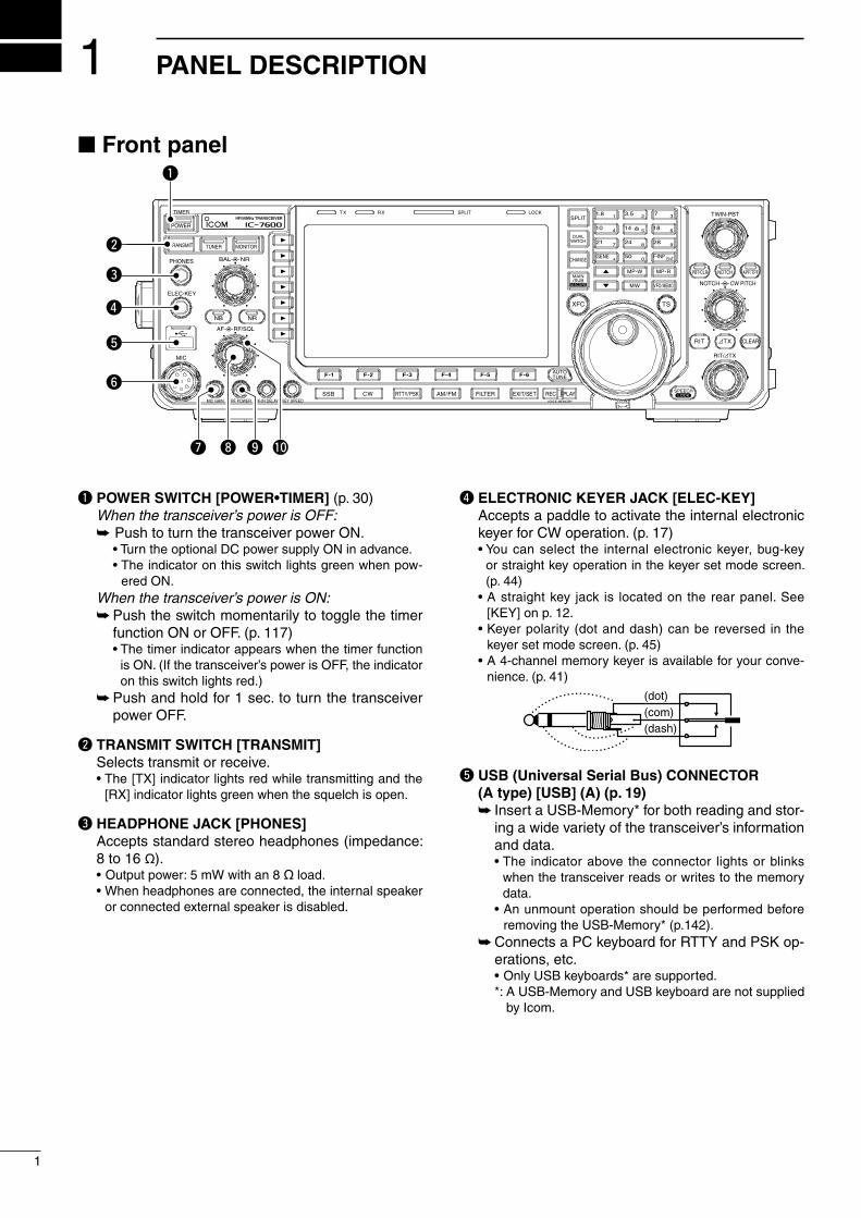
q POWER SWITCH [POWER•TIMER] (p. 30) When the transceiver’s power is OFF: Push to turn the transcever power ON. • Turn the optonal DC power supply ON n advance. • The ndcator on ths swtch lghts green when pow-
ered ON. When the transceiver’s power is ON: Push the swtch momentarly to toggle the tmer
functon ON or OFF. (p. 117) • The tmer ndcator appears when the tmer functon
s ON. (If the transcever’s power s OFF, the ndcator on ths swtch lghts red.)
Push and hold for 1 sec. to turn the transcever power OFF.
w TRANSMIT SWITCH [TRANSMIT] Selects transmt or receve. • The [TX] ndcator lghts red whle transmttng and the
[RX] ndcator lghts green when the squelch s open.
e HEADPHONE JACK [PHONES] Accepts standard stereo headphones (mpedance:
8 to 16 ø). • Output power: 5 mW wth an 8 ø load. • When headphones are connected, the nternal speaker
or connected external speaker s dsabled.
r ELECTRONIC KEYER JACK [ELEC-KEY] Accepts a paddle to actvate the nternal electronc
keyer for CW operaton. (p. 17) • You can select the nternal electronc keyer, bug-key
or straght key operaton n the keyer set mode screen. (p. 44)
• A straght key jack s located on the rear panel. See [KEY] on p. 12.
• Keyer polarty (dot and dash) can be reversed n the keyer set mode screen. (p. 45)
• A 4-channel memory keyer s avalable for your conve-nence. (p. 41)
(dot)(com)(dash)
t USB (Universal Serial Bus) CONNECTOR (A type) [USB] (A) (p. 19)
Insert a USB-Memory* for both readng and stor-ng a wde varety of the transcever’s nformaton and data.
• The ndcator above the connector lghts or blnks when the transcever reads or wrtes to the memory data.
• An unmount operaton should be performed before removng the USB-Memory* (p.142).
Connects a PC keyboard for RTTY and PSK op-eratons, etc.
• Only USB keyboards* are supported. *: A USB-Memory and USB keyboard are not suppled
by Icom.
Front panel
TWIN-PBT
RIT/ TX
NOTCH CW PITCH
VOICE MEMORY
BAL NR
AF RF/SQL
MIC GAIN RF POWER BK-IN DELAY KEY SPEED
TIMER
PHONES
ELEC-KEY
MIC
AUTOTUNE
GENE F-INP
1.8 3.51 2
14 5 18 6
7 3
24 8 28 9
50 0 ENT
4
7
10
21
CHANGE
TSXFC
SPLIT
DUALWATCH
MAIN/SUB
VFO/MEMO
MP-W
MW
MP-R
F-6F-5F-4F-3F-2F-1
NRNB
PBT-CLR APF/TPFNOTCH
POWER
RIT CLEARTX
SPEECHLOCKFILTER REC PLAYEXIT/SETSSB CW RTTY/PSK AM/FM
MONITORTRANSMIT TUNER
HF/50MHz TRANSCEIVERLOCKTX RX SPLIT
q
w
e
y
t
r
u i o !0
1
1
PANEL DESCRIPTION
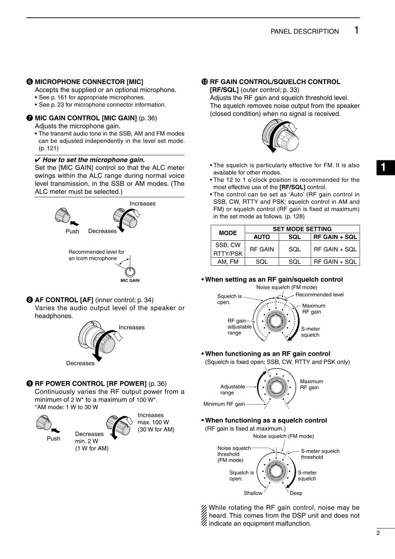
y MICROPHONE CONNECTOR [MIC] Accepts the suppled or an optonal mcrophone. • See p. 161 for approprate mcrophones. • See p. 23 for mcrophone connector nformaton.
u MIC GAIN CONTROL [MIC GAIN] (p. 36) Adjusts the mcrophone gan. • The transmt audo tone n the SSB, AM and FM modes
can be adjusted ndependently n the level set mode. (p. 121)
How to set the microphone gain.Set the [MIC GAIN] control so that the ALC meter swngs wthn the ALC range durng normal voce level transmsson, n the SSB or AM modes. (The ALC meter must be selected.)
MIC GAIN
Recommended level for an Icom microphone
Increases
DecreasesPush
i AF CONTROL [AF] (nner control; p. 34) Vares the audo output level of the speaker or
headphones.
Increases
Decreases
o RF POWER CONTROL [RF POWER] (p. 36) Contnuously vares the RF output power from a
mnmum of 2 W* to a maxmum of 100 W*. *AM mode: 1 W to 30 W
Increasesmax. 100 W(30 W for AM)
Decreasesmin. 2 W(1 W for AM)
Push
!0 RF GAIN CONTROL/SQUELCH CONTROL [RF/SQL] (outer control; p. 33)
Adjusts the RF gan and squelch threshold level. The squelch removes nose output from the speaker
(closed condton) when no sgnal s receved.
• The squelch s partcularly effectve for FM. It s also avalable for other modes.
• The 12 to 1 o’clock poston s recommended for the most effectve use of the [RF/SQL] control.
• The control can be set as ‘Auto’ (RF gan control n SSB, CW, RTTY and PSK; squelch control n AM and FM) or squelch control (RF gan s fxed at maxmum) n the set mode as follows. (p. 128)
MODESET MODE SETTING
AUTO SQL RF GAIN + SQLSSB, CW
RTTY/PSKRF GAIN SQL RF GAIN + SQL
AM, FM SQL SQL RF GAIN + SQL
• When setting as an RF gain/squelch control
Maximum RF gain
S-meter squelch
Noise squelch (FM mode)
Squelch is open.
RF gain adjustablerange
Recommended level
• When functioning as an RF gain control (Squelch s fixed open; SSB, CW, RTTY and PSK only)
Minimum RF gain
Adjustablerange
Maximum RF gain
• When functioning as a squelch control (RF gan s fixed at maxmum.)
Squelch is open.
S-meter squelch
S-meter squelchthreshold
Noise squelch threshold (FM mode)
Shallow Deep
Noise squelch (FM mode)
Whle rotatng the RF gan control, nose may be heard. Ths comes from the DSP unt and does not ndcate an equpment malfuncton.
2
1PANEL DESCRIPTION
1
2
3
4
5
6
7
8
9
10
11
12
13
14
15
16
17
18
19
20
21

!1 BREAK-IN DELAY CONTROL [BK-IN DELAY] (p. 85)
Adjusts the transmt-to-receve swtchng delay tme for CW sem-break-n operatons.
PushShort delay for high speed keying (2 dots)
Long delay for slow speed keying (13 dots)
!2 ELECTRONIC CW KEYER SPEED CONTROL [KEY SPEED] (p. 85)
Adjusts keyng speed for the nternal electronc CW keyer from 6 wpm (mn.) to 48 wpm (max.).
Push Slow(6 wpm)
Fast(48 wpm)
!3 MULTI-FUNCTION SWITCHES Push to select the functons ndcated n the LCD
dsplay to the rght of these swtches. • Functons vary, dependng on the operatng condton.
MF1 (MULTI-FUNCTION 1 SWITCH)ANT SWITCH (ANT)
Selects the antenna connector be-tween ANT1 and ANT2 when pushed. (p. 112)
Turns the [RX ANT] (receve antenna) ON or OFF when pushed and held for 1 sec.
• When the receve antenna s actvated, the antenna connected to [ANT1] or [ANT2] s used for transmttng only.
When a transverter s n use, [ANT] does not functon and ‘TRV’ appears.
MF2 (MULTI-FUNCTION 2 SWITCH)METER SWITCH (METER) (p. 34)
Selects the RF power (Po), SWR, ALC, COMP, Vd or Id meterng functons durng transmt.
Swtches the mult-functon dgtal meter ON or OFF when pushed and held for 1 sec.
Front panel (contnued)
TWIN-PBT
RIT/ TX
NOTCH CW PITCH
VOICE MEMORY
BAL NR
AF RF/SQL
MIC GAIN RF POWER BK-IN DELAY KEY SPEED
TIMER
PHONES
ELEC-KEY
MIC
AUTOTUNE
M.SCOPE
GENE F-INP
1.8 3.51 2
14 5 18 6
7 3
24 8 28 9
50 0 ENT
4
7
10
21
CHANGE
TSXFC
SPLIT
DUALWATCH
MAIN/SUB
VFO/MEMO
MP-W
MW
MP-R
F-6F-5F-4F-3F-2F-1
NRNB
PBT-CLR APF/TPFNOTCH
POWER
RIT CLEARTX
SPEECHLOCKFILTER REC PLAYEXIT/SETSSB CW RTTY/PSK AM/FM
MONITORTRANSMIT TUNER
HF/50MHz TRANSCEIVERLOCKTX RX SPLIT
!1 !2
!3
3
1 PANEL DESCRIPTION

MF3 (MULTI-FUNCTION 3 SWITCH)P.AMP SWITCH (P.AMP) (p. 72)
Selects one of 2 receve RF preamps or bypasses them.
• “P. AMP1” actvates a 10 dB preamp. • “ P. AMP2” actvates a 16 dB hgh-gan
preamp. • “P. AMP OFF” can also be selected. Turns the preamp functon OFF when
pushed and held for 1 sec.
What is the preamp?The preamp amplfies sgnals n the front end to m-prove the S/N rato and senstvty. Select “P. AMP1” or “P. AMP2” when recevng weak sgnals.
MF4 (MULTI-FUNCTION 4 SWITCH)ATT SWITCH (ATT) (p. 72)
Selects a 6 dB, 12 dB or 18 dB attenu-ator when pushed.
• “ATT OFF” can also be selected. Turns the attenuator functon OFF
when pushed and held for 1 sec.
What is the attenuator?The attenuator prevents a desred sgnal from beng dstorted when very strong sgnals are near t, or when very strong electromagnetc fields, such as from a broadcastng staton, are near your locaton.
MF5 (MULTI-FUNCTION 5 SWITCH)AGC SWITCH (AGC) (p. 74)
Actvates and selects a fast, mddle or slow AGC tme constant when pushed.
• In the FM mode, only “FAST” s aval-able.
Selects the AGC set mode when pushed and held for 1 sec.
The AGC tme constant can be set be-tween 0.1 and 8.0 sec. (dependng on the mode), or turned OFF. When the AGC s OFF, the S-meter does not functon.
What is the AGC?The AGC controls the recever gan to produce a constant audo output level, even when the receved sgnal strength vares dramatcally. Select “FAST” for tunng and then select “MID” or “SLOW,” depend-ng on the recevng condton.
MF6 (MULTI-FUNCTION 6 SWITCH)VOX SWITCH (VOX) (p. 84)
Push to turn the VOX functon ON or OFF durng the SSB, AM and FM mode operaton.
Push and hold for 1 sec. to select the VOX set mode.
What is the VOX function?The VOX functon (voce operated transmsson) actvates transmsson wthout pushng the trans-mt swtch or PTT swtch when you speak nto the mcrophone; then automatcally returns to receve when you stop speakng.
BK-IN SWITCH (BK-IN) (p. 85) Selects sem break-n, full break-n op-
eraton n the CW mode, or turns the break-n operaton OFF when pushed.
What is the break-in function?The break-n functon swtches transmt and receve wth CW keyng. Full break-n functon (QSK), you can montor the receve sgnal durng keyng.
MF7 (MULTI-FUNCTION 7 SWITCH)COMP SWITCH (COMP) (p. 86)
Turns the speech compressor ON or OFF n the SSB mode.
Selects the compresson between nar-row, md or wde when pushed and held for 1 sec.
What is the speech compressor?The speech compressor compresses the transmt-ter audo nput to ncrease the average audo output level, n order to ncrease talk power. Ths functon s effectve for long-dstance communcaton, or when propagaton condtons are poor.
1⁄4 SWITCH (1⁄4) (p. 30) Turns the 1⁄4 speed tunng functon ON
or OFF n the SSB data, CW, RTTY and PSK modes.
• The 1⁄4 functon sets the dal speed to 1⁄4 of t’s normal speed for fine tunng.
TONE SWITCH (TONE) (pgs. 62, 63) Swtches between the tone encoder,
tone squelch functon and no-tone op-eraton when pushed n the FM mode.
Selects the tone set mode when pushed and held for 1 sec. n the FM mode.
4
1PANEL DESCRIPTION
1
2
3
4
5
6
7
8
9
10
11
12
13
14
15
16
17
18
19
20
21
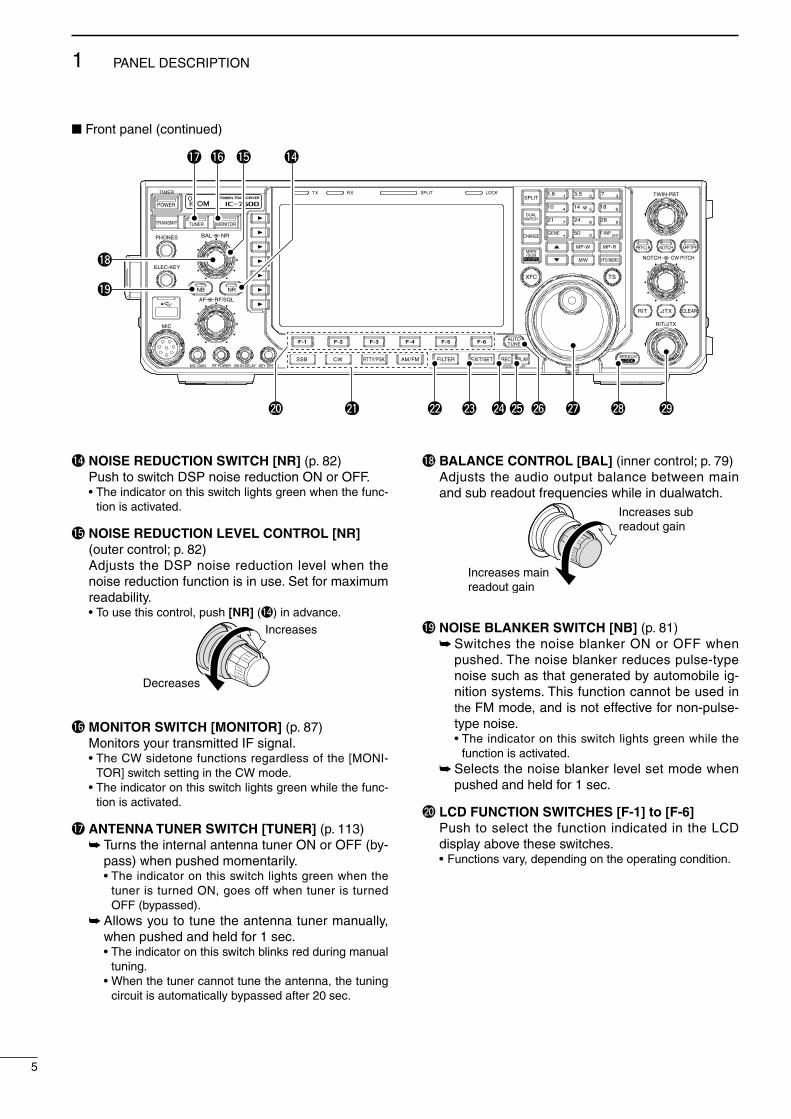
!4 NOISE REDUCTION SWITCH [NR] (p. 82) Push to swtch DSP nose reducton ON or OFF. • The ndcator on ths swtch lghts green when the func-
ton s actvated.
!5 NOISE REDUCTION LEVEL CONTROL [NR] (outer control; p. 82)
Adjusts the DSP nose reducton level when the nose reducton functon s n use. Set for maxmum readablty.
• To use ths control, push [NR] (!4) n advance.
Decreases
Increases
!6 MONITOR SWITCH [MONITOR] (p. 87) Montors your transmtted IF sgnal. • The CW sdetone functons regardless of the [MONI-
TOR] swtch settng n the CW mode. • The ndcator on ths swtch lghts green whle the func-
ton s actvated.
!7 ANTENNA TUNER SWITCH [TUNER] (p. 113) Turns the nternal antenna tuner ON or OFF (by-
pass) when pushed momentarly. • The ndcator on ths swtch lghts green when the
tuner s turned ON, goes off when tuner s turned OFF (bypassed).
Allows you to tune the antenna tuner manually, when pushed and held for 1 sec.
• The ndcator on ths swtch blnks red durng manual tunng.
• When the tuner cannot tune the antenna, the tunng crcut s automatcally bypassed after 20 sec.
!8 BALANCE CONTROL [BAL] (nner control; p. 79) Adjusts the audo output balance between man
and sub readout frequences whle n dualwatch.
Increases mainreadout gain
Increases subreadout gain
!9 NOISE BLANKER SWITCH [NB] (p. 81) Swtches the nose blanker ON or OFF when
pushed. The nose blanker reduces pulse-type nose such as that generated by automoble g-nton systems. Ths functon cannot be used n the FM mode, and s not effectve for non-pulse-type nose.
• The ndcator on ths swtch lghts green whle the functon s actvated.
Selects the nose blanker level set mode when pushed and held for 1 sec.
@0 LCD FUNCTION SWITCHES [F-1] to [F-6] Push to select the functon ndcated n the LCD
dsplay above these swtches. • Functons vary, dependng on the operatng condton.
Front panel (contnued)
TWIN-PBT
RIT/ TX
NOTCH CW PITCH
VOICE MEMORY
BAL NR
AF RF/SQL
MIC GAIN RF POWER BK-IN DELAY KEY SPEED
TIMER
PHONES
ELEC-KEY
MIC
AUTOTUNE
GENE F-INP
1.8 3.51 2
14 5 18 6
7 3
24 8 28 9
50 0 ENT
4
7
10
21
CHANGE
TSXFC
SPLIT
DUALWATCH
MAIN/SUB
M.SCOPE VFO/MEMO
MP-W
MW
MP-R
F-6F-5F-4F-3F-2F-1
NRNB
PBT-CLR APF/TPFNOTCH
POWER
RIT CLEARTX
SPEECHLOCKFILTER REC PLAYEXIT/SETSSB CW RTTY/PSK AM/FM
MONITORTRANSMIT TUNER
HF/50MHz TRANSCEIVERLOCKTX RX SPLIT
!4!5!6!7
!9
!8
@0 @1 @2 @3 @7 @8 @9@6@5@4
5
1 PANEL DESCRIPTION

@1 MODE SWITCHES Selects the desred mode. (p. 32) • Announces the selected mode va the speech synthe-
szer. (p. 35)
[SSB] Selects the USB and LSB modes alternately
when pushed. Selects the SSB data mode (USB-D, LSB-D) when
pushed and held for 1 sec. n the SSB mode. • In the SSB data mode, push to return to the SSB
mode. Swtches D1, D2 and D3 when pushed and held
for 1 sec. n the SSB data mode.
[CW] Alternately selects the CW and CW-R (CW reverse)
modes when pushed.
[RTTY/PSK] Alternately selects the RTTY and PSK modes
when pushed. Swtches the RTTY and RTTY-R (RTTY reverse)
mode when pushed and held for 1 sec. n the RTTY mode.
Swtches the PSK and PSK-R (PSK reverse) mode when pushed and held for 1 sec. n PSK mode.
[AM/FM] Alternately selects the AM and FM modes. Selects the AM or FM data mode (AM-D/FM-D)
when pushed and held for 1 sec. n the AM or FM mode, respectvely.
• In the AM or FM data mode, push to return to the AM or FM mode, respectvely.
Swtches D1, D2 and D3 when pushed and held for 1 sec. n the AM or FM data mode.
@2 FILTER SWITCH [FILTER] (p. 76) Push to select one of 3 IF filter settngs. Push and hold for 1 sec. to dsplay the filter set
screen.
@3 EXIT/SET SWITCH [EXIT/SET] Push to ext, or return to the prevous screen ds-
play durng spectrum scope, memory, scan or set mode screen dsplay.
Push and hold for 1 sec. to dsplay the set mode menu screen.
@4 VOICE MEMORY RECORD SWITCH [REC] (p. 91) Push to store the prevous receved sgnal for the
preset tme perod. • The preset tme perod can be set n the voce set
mode. (p. 97) Push and hold for 1 sec. to start recordng the
receved sgnal untl the recordng s stopped. • Push ths swtch momentarly to stop recordng. • The memory records the latest 30 sec. of audo.
@5 VOICE MEMORY PLAYBACK SWITCH [PLAY] (p. 92)
Push to playback the selected voce memory n the RX memory screen for the preset tme perod.
• When the RX memory screen s not dsplayed, the prevously recorded audo s played back for the pre-set tme perod.
Push and hold for 1 sec. to playback all of the se-lected voce memory n the RX memory screen.
• When the RX memory screen s not dsplayed, all of the prevously recorded audo s played back.
@6 AUTOMATIC TUNING SWITCH [AUTO TUNE] (p. 83)
Turns the automatc tunng functon ON or OFF n the CW and AM modes.
IMPORTANT!When recevng a weak sgnal, or recevng a sg-nal wth nterference, the automatc tunng func-ton may tune the recever to an undesred sgnal.
@7 MAIN DIAL Changes the dsplayed frequency, selects the set
mode settng, etc.
@8 SPEECH/LOCK SWITCH [SPEECH/LOCK] Push to audbly announce the S-meter dsplay,
the dsplayed frequency and the operatng mode. (p. 35)
• The parameters to be announced can be selected n the Others set mode. (p. 131)
Push and hold for 1 sec. to turn the dal lock func-ton ON or OFF. (p. 82)
• The dal lock functon electroncally locks the man dal.
• The lock ndcator lghts whle the dal lock functon s actvated.
NOTE: The [SPEECH/LOCK] swtch operaton to actvate the voce syntheszer or the dal lock functons can be replaced n the Others set mode. (p. 131)
@9 RIT/∂TX CONTROL [RIT/∂TX] (pgs. 73, 87) Shfts the receve and/or transmt frequency wth-
out changng the transmt and/or receve frequency shown on the man VFO whle the RIT and/or ∂TX functons are/s ON.
• Rotate the control clockwse to ncrease the frequency, or rotate the control counterclockwse to decrease the frequency. The RIT or ∂TX functons must be ON.
• The shft frequency range s ±9.999 kHz n 1 Hz steps (or ±9.99 kHz n 10 Hz steps).
Shift low
Shift high
6
1PANEL DESCRIPTION
1
2
3
4
5
6
7
8
9
10
11
12
13
14
15
16
17
18
19
20
21

#0 TRANSMIT INDICATOR [TX] Lghts red whle transmttng.
#1 RECEIVE INDICATOR [RX] Lghts green whle recevng a sgnal and when the
squelch s open.
#2 LCD FUNCTION DISPLAY (p. 13) Shows the operatng frequency, functon swtch
menus, spectrum scope screen, memory lst screen, set mode settngs, etc.
#3 SPLIT OPERATION INDICATOR [SPLIT] (p. 88) Lghts durng splt frequency operaton.
#4 MAIN/SUB CHANGE SWITCH [CHANGE] Swtches the frequency and selected memory
channel between man and sub readouts when pushed.
• Swtches between transmt frequency and receve frequency when the splt frequency functon s ON. (p. 88)
Equalzes the sub readout frequency to the man readout frequency when pushed and held for 1 sec.
#5 LOCK INDICATOR [LOCK] (p. 82) Lghts when the dal lock functon s actvated.
#6 DUALWATCH SWITCH [DUALWATCH] (p. 79) Push to turn the dualwatch functon ON or OFF. • “ ” appears when the dualwatch functon
ON. Push and hold for 1 sec. to turn the dualwatch
functon ON and equalze the sub readout fre-quency to the man readout. (Quck dualwatch functon)
• The quck dualwatch functon can be turned OFF n the Others set mode. (p. 128)
#7 SPLIT SWITCH [SPLIT] (p. 88) Push to turn the splt functon ON or OFF. • “ ” appears when the splt functon s n
use. Push and hold for 1 sec. to actvate the quck
splt functon. • Turns the splt functon ON and equalzes the sub
readout frequency to the man readout and sets the sub readout for frequency nput n the non-FM modes. (p. 89)
• The offset frequency s shfted from the selected VFO frequency n the FM mode. (p. 129)
• The tone encoder functon s turned ON n the FM mode.
• The quck splt functon can be turned OFF n the Others set mode. (p. 129)
#8 KEYPAD Pushng a key selects the operatng band. (p. 27) • [GEN •] selects the general coverage band. Pushng the same key 2 or 3 tmes calls up
other stacked frequences n the band. (p. 27) • Icom’s trple band stackng regster memorzes 3 fre-
quences n each band. After pushng [F-INP ENT], push a key on the
keypad to enter a numerc frequency. After en-terng, push [F-INP ENT] to select the desred frequency drectly (p. 28)
• e.g. to enter 14.195 MHz; Push [F-INP ENT] [1] [4] [•] [1] [9] [5] [F-INP ENT]. After pushng [F-INP ENT], push a key on the
keypad to enter a memory channel. After enter-ng, push [∫] or [√] to drectly select the desred memory channel. (p. 99)
Front panel (contnued)
TWIN-PBT
RIT/ TX
NOTCH CW PITCH
VOICE MEMORY
BAL NR
AF RF/SQL
MIC GAIN RF POWER BK-IN DELAY KEY SPEED
TIMER
PHONES
ELEC-KEY
MIC
AUTOTUNE
GENE F-INP
1.8 3.51 2
14 5 18 6
7 3
24 8 28 9
50 0 ENT
4
7
10
21
CHANGE
TSXFC
SPLIT
DUALWATCH
MAIN/SUB
M.SCOPE VFO/MEMO
MP-W
MW
MP-R
F-6F-5F-4F-3F-2F-1
NRNB
PBT-CLR APF/TPFNOTCH
POWER
RIT CLEARTX
SPEECHLOCKFILTER REC PLAYEXIT/SETSSB CW RTTY/PSK AM/FM
MONITORTRANSMIT TUNER
HF/50MHz TRANSCEIVERLOCKTX RX SPLIT
$2
$3
#0 #5#4 #6 #7 #8 #9
$0
#3#2#1
$1
$4$5
7
1 PANEL DESCRIPTION
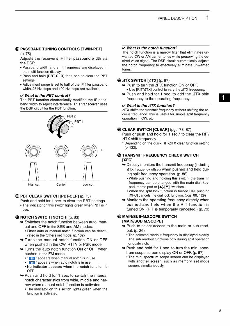
#9 PASSBAND TUNING CONTROLS [TWIN-PBT] (p. 75)
Adjusts the recever’s IF flter passband wdth va the DSP.
• Passband wdth and shft frequency are dsplayed n the mult-functon dsplay.
• Push and hold [PBT-CLR] for 1 sec. to clear the PBT settngs.
• Adjustment range s set to half of the IF filter passband wdth. 25 Hz steps and 100 Hz steps are avalable.
What is the PBT control?The PBT functon electroncally modfes the IF pass-band wdth to reject nterference. Ths transcever uses the DSP crcut for the PBT functon.
PBT2
PBT1
– +
Low cutHigh cut Center
$0 PBT CLEAR SWITCH [PBT-CLR] (p. 75) Push and hold for 1 sec. to clear the PBT settngs. • The ndcator on ths swtch lghts green when PBT s n
use.
$1 NOTCH SWITCH [NOTCH] (p. 83) Swtches the notch functon between auto, man-
ual and OFF n the SSB and AM modes. • Ether auto or manual notch functon can be deact-
vated n the Others set mode. (p. 132) Turns the manual notch functon ON or OFF
when pushed n the CW, RTTY or PSK mode. Turns the auto notch functon ON or OFF when
pushed n the FM mode. • “ ” appears when manual notch s n use. • “ ” appears when auto notch s n use. • No ndcator appears when the notch functon s
OFF. Push and hold for 1 sec. to swtch the manual
notch characterstcs from wde, mddle and nar-row when manual notch functon s actvated.
• The ndcator on ths swtch lghts green when the functon s actvated.
What is the notch function?The notch functon s a narrow flter that elmnates un-wanted CW or AM carrer tones whle preservng the de-sred voce sgnal. The DSP crcut automatcally adjusts the notch frequency to effectvely elmnate unwanted tones.
$2 ∂TX SWITCH [∂TX] (p. 87) Push to turn the ∂TX functon ON or OFF. • Use [RIT/∂TX] control to vary the ∂TX frequency. Push and hold for 1 sec. to add the ∂TX shft
frequency to the operatng frequency.
What is the ∂TX function?∂TX shfts the transmt frequency wthout shftng the re-ceve frequency. Ths s useful for smple splt frequency operaton n CW, etc.
$3 CLEAR SWITCH [CLEAR] (pgs. 73, 87) Push or push and hold for 1 sec.* to clear the RIT/
∂TX shft frequency. * Dependng on the quck RIT/∂TX clear functon settng
(p. 132).
$4 TRANSMIT FREQUENCY CHECK SWITCH [XFC]
Drectly montors the transmt frequency (ncludng ∂TX frequency offset) when pushed and held dur-ng splt frequency operaton. (p. 88)
• Whle pushng and holdng ths swtch, the transmt frequency can be changed wth the man dal, key-pad, memo pad or [∫]/[√] swtches.
• When the splt lock functon s turned ON, pushng [XFC] cancels the dal lock functon. (pgs. 88, 129)
Montors the operatng frequency drectly when pushed and held when the RIT functon s turned ON. (RIT s temporarly cancelled.) (p. 73)
$5 MAIN/SUB•M.SCOPE SWITCH [MAIN/SUB M.SCOPE]
Push to select access to the man or sub read-out. (p. 26)
• The selected readout frequency s dsplayed clearly. The sub readout functons only durng splt operaton or dualwatch.
Push and hold for 1 sec. to turn the mn spec-trum scope screen dsplay ON or OFF. (p. 67)
• The mn spectrum scope screen can be dsplayed wth another screen, such as memory, set mode screen, smultaneously.
8
1PANEL DESCRIPTION
1
2
3
4
5
6
7
8
9
10
11
12
13
14
15
16
17
18
19
20
21
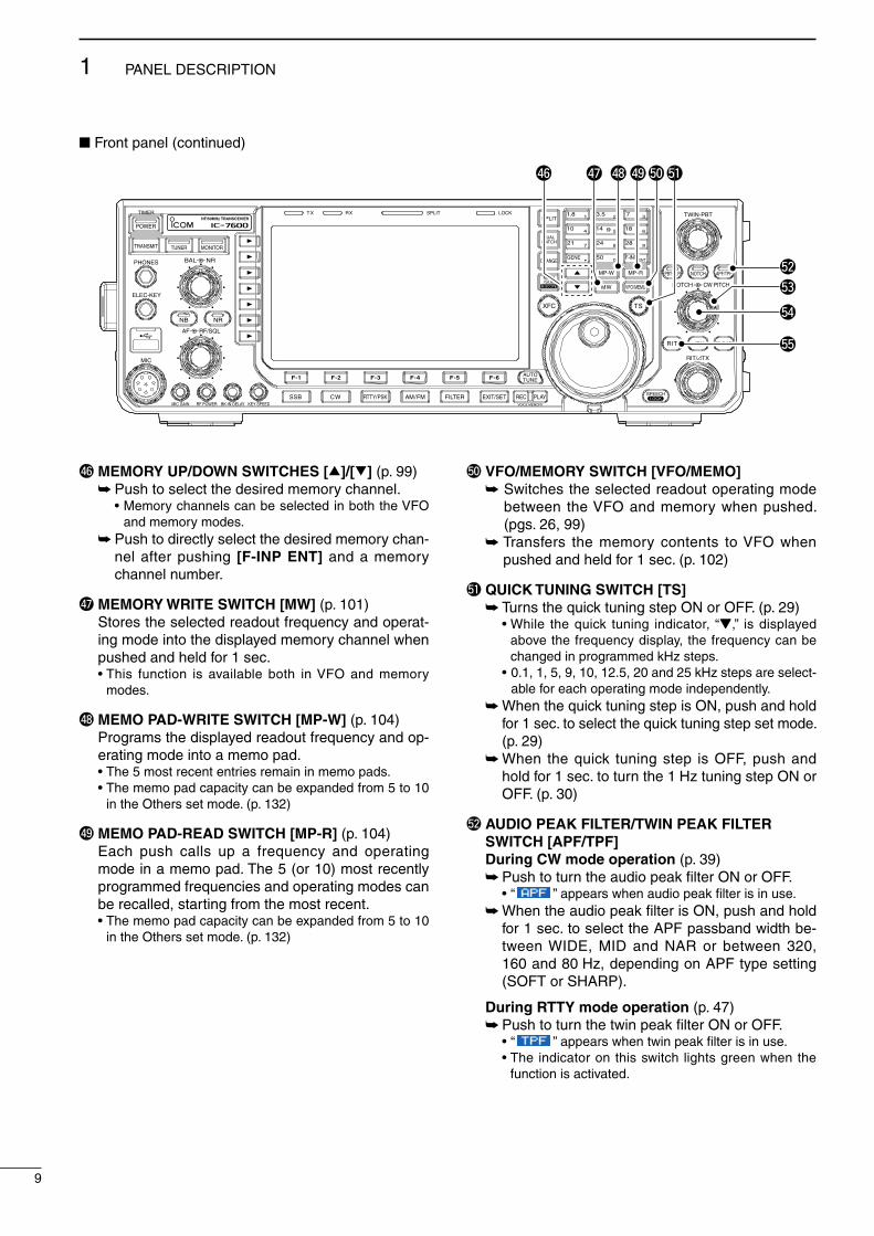
$6 MEMORY UP/DOWN SWITCHES [∫]/[√] (p. 99) Push to select the desred memory channel. • Memory channels can be selected n both the VFO
and memory modes. Push to drectly select the desred memory chan-
nel after pushng [F-INP ENT] and a memory channel number.
$7 MEMORY WRITE SWITCH [MW] (p. 101) Stores the selected readout frequency and operat-
ng mode nto the dsplayed memory channel when pushed and held for 1 sec.
• Ths functon s avalable both n VFO and memory modes.
$8 MEMO PAD-WRITE SWITCH [MP-W] (p. 104) Programs the dsplayed readout frequency and op-
eratng mode nto a memo pad. • The 5 most recent entres reman n memo pads. • The memo pad capacty can be expanded from 5 to 10
n the Others set mode. (p. 132)
$9 MEMO PAD-READ SWITCH [MP-R] (p. 104) Each push calls up a frequency and operatng
mode n a memo pad. The 5 (or 10) most recently programmed frequences and operatng modes can be recalled, startng from the most recent.
• The memo pad capacty can be expanded from 5 to 10 n the Others set mode. (p. 132)
%0 VFO/MEMORY SWITCH [VFO/MEMO] Swtches the selected readout operatng mode
between the VFO and memory when pushed. (pgs. 26, 99)
Transfers the memory contents to VFO when pushed and held for 1 sec. (p. 102)
%1 QUICK TUNING SWITCH [TS] Turns the quck tunng step ON or OFF. (p. 29) • Whle the quck tunng ndcator, “Z,” s dsplayed
above the frequency dsplay, the frequency can be changed n programmed kHz steps.
• 0.1, 1, 5, 9, 10, 12.5, 20 and 25 kHz steps are select-able for each operatng mode ndependently.
When the quck tunng step s ON, push and hold for 1 sec. to select the quck tunng step set mode. (p. 29)
When the quck tunng step s OFF, push and hold for 1 sec. to turn the 1 Hz tunng step ON or OFF. (p. 30)
%2 AUDIO PEAK FILTER/TWIN PEAK FILTER SWITCH [APF/TPF]
During CW mode operation (p. 39) Push to turn the audo peak filter ON or OFF. • “ ” appears when audo peak filter s n use. When the audo peak filter s ON, push and hold
for 1 sec. to select the APF passband wdth be-tween WIDE, MID and NAR or between 320, 160 and 80 Hz, dependng on APF type settng (SOFT or SHARP).
During RTTY mode operation (p. 47) Push to turn the twn peak filter ON or OFF. • “ ” appears when twn peak filter s n use. • The ndcator on ths swtch lghts green when the
functon s actvated.
Front panel (contnued)
TWIN-PBT
RIT/ TX
NOTCH CW PITCH
VOICE MEMORY
BAL NR
AF RF/SQL
MIC GAIN RF POWER BK-IN DELAY KEY SPEED
TIMER
PHONES
ELEC-KEY
MIC
AUTOTUNE
GENE F-INP
1.8 3.51 2
14 5 18 6
7 3
24 8 28 9
50 0 ENT
4
7
10
21
CHANGE
TSXFC
SPLIT
DUALWATCH
MAIN/SUB
M.SCOPE VFO/MEMO
MP-W
MW
MP-R
F-6F-5F-4F-3F-2F-1
NRNB
PBT-CLR APF/TPFNOTCH
POWER
RIT CLEARTX
SPEECHLOCKFILTER REC PLAYEXIT/SETSSB CW RTTY/PSK AM/FM
MONITORTRANSMIT TUNER
HF/50MHz TRANSCEIVERLOCKTX RX SPLIT
$6
%2
$7 $8 $9%0%1
%3
%4
%5
9
1 PANEL DESCRIPTION
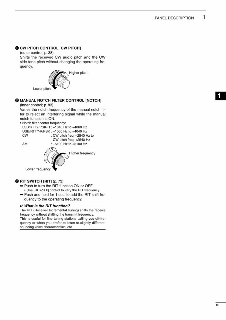
%3 CW PITCH CONTROL [CW PITCH] (outer control; p. 38) Shfts the receved CW audo ptch and the CW
sde-tone ptch wthout changng the operatng fre-quency.
Lower pitch
Higher pitch
%4 MANUAL NOTCH FILTER CONTROL [NOTCH] (nner control; p. 83)
Vares the notch frequency of the manual notch fil-ter to reject an nterferng sgnal whle the manual notch functon s ON.
• Notch filter center frequency: LSB/RTTY/PSK-R : –1040 Hz to +4060 Hz USB/RTTY-R/PSK : –1060 Hz to +4040 Hz CW : CW ptch freq. –2540 Hz to
CW ptch freq. +2540 Hz AM : –5100 Hz to +5100 Hz
Lower frequency
Higher frequency
%5 RIT SWITCH [RIT] (p. 73) Push to turn the RIT functon ON or OFF. • Use [RIT/∂TX] control to vary the RIT frequency. Push and hold for 1 sec. to add the RIT shft fre-
quency to the operatng frequency.
What is the RIT function?The RIT (Recever Incremental Tunng) shfts the receve frequency wthout shftng the transmt frequency.Ths s useful for fine tunng statons callng you off-fre-quency or when you prefer to lsten to slghtly dfferent-soundng voce characterstcs, etc.
10
1PANEL DESCRIPTION
1
2
3
4
5
6
7
8
9
10
11
12
13
14
15
16
17
18
19
20
21
Rear panel
1 2ANT DC 13.8V
X-VERTERRX-ANT ACC
TUNER
IN OUT ALC SEND KEY1 2 METER REMOTE EXT-SP
q w re
tyo!0!1!2!7 !6 !5 !4 !3 i u
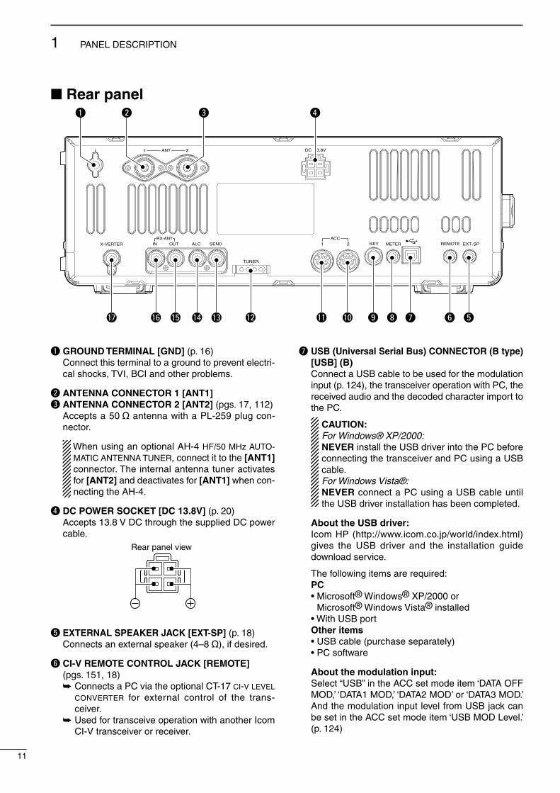
q GROUND TERMINAL [GND] (p. 16) Connect ths termnal to a ground to prevent electr-
cal shocks, TVI, BCI and other problems.
w ANTENNA CONNECTOR 1 [ANT1]e ANTENNA CONNECTOR 2 [ANT2] (pgs. 17, 112) Accepts a 50 ø antenna wth a PL-259 plug con-
nector.
When usng an optonal AH-4 HF/50 MHz AUTO-MATIC ANTENNA TUNER, connect t to the [ANT1] connector. The nternal antenna tuner actvates for [ANT2] and deactvates for [ANT1] when con-nectng the AH-4.
r DC POWER SOCKET [DC 13.8V] (p. 20) Accepts 13.8 V DC through the suppled DC power
cable.Rear panel view
t EXTERNAL SPEAKER JACK [EXT-SP] (p. 18) Connects an external speaker (4–8 ø), f desred.
y CI-V REMOTE CONTROL JACK [REMOTE] (pgs. 151, 18)
Connects a PC va the optonal CT-17 ci-v level converter for external control of the trans-cever.
Used for transceve operaton wth another Icom CI-V transcever or recever.
u USB (Universal Serial Bus) CONNECTOR (B type) [USB] (B)
Connect a USB cable to be used for the modulaton nput (p. 124), the transcever operaton wth PC, the receved audo and the decoded character mport to the PC.
CAUTION: For Windows® XP/2000:NEVER nstall the USB drver nto the PC before connectng the transcever and PC usng a USB cable.For Windows Vista®:NEVER connect a PC usng a USB cable untl the USB drver nstallaton has been completed.
About the USB driver: Icom HP (http://www.com.co.jp/world/ndex.html)
gves the USB drver and the nstallaton gude download servce.
The followng tems are requred: PC • Mcrosoft® Wndows® XP/2000 or
Mcrosoft® Wndows Vsta® nstalled • Wth USB port Other items • USB cable (purchase separately) • PC software
About the modulation input: Select “USB” n the ACC set mode tem ‘DATA OFF
MOD,’ ‘DATA1 MOD,’ ‘DATA2 MOD’ or ‘DATA3 MOD.’ And the modulaton nput level from USB jack can be set n the ACC set mode tem ‘USB MOD Level.’ (p. 124)
11
1 PANEL DESCRIPTION

i METER JACK [METER] (p. 19) Outputs a sgnal showng receved sgnal strength,
transmt output power, VSWR, ALC, speech com-presson, Vd or Id level for external meter dsplay.
o STRAIGHT KEY JACK [KEY] (p. 17) Accepts a straght key or external electronc keyer
output usng a standard 1⁄4 nch plug. • [ELEC-KEY] on the front panel can be used for a
straght key or external electronc keyer. Deactvate the nternal electronc keyer n the keyer set mode. (p. 45)
(+)
(_)
!0 ACCESSORY SOCKET 2 [ACC 2] !1 ACCESSORY SOCKET 1 [ACC 1] Enable connecton of external equpment such as
a lnear amplfier, an automatc antenna selector/ tuner, a TNC for data communcatons, etc.
• See p. 24 for socket nformaton.
!2 TUNER CONTROL SOCKET [TUNER] (p. 18) Accepts the control cable from an optonal AH-4
HF/50 MHz AUTOMATIC ANTENNA TUNER.
!3 SEND CONTROL JACK [SEND] (p. 18) Connects to ground when transmttng to control an
external unt, such as a non-Icom lnear amplfier.
NOTE: T/R control voltage and current must be less than 16 V DC/0.5 A (or 250 V AC, 200 mA wth MOSFET swtchng).
!4 ALC INPUT JACK [ALC] (p. 18) Connects to the ALC output jack of a non-Icom ln-
ear amplfier.
!5 RECEIVE ANTENNA OUT [RX ANT– OUT]!6 RECEIVE ANTENNA IN [RX ANT– IN] Located between the transmt/receve swtchng cr-
cut and recever’s RF stage.
Connects an external unt, such as preamplfier or RF filter, usng RCA connectors, f desred.
In ths case, the antenna connector must be se-lected as “ANT 1/R” or “ANT 2/R.” (p. 112)
• When no external unt s connected, “ANT 1” or “ANT 2” must be selected.
Transmitter
IN
[RX ANT]
OUT
Transmit/Receiveswitching circuit
ANT
Receiver
!7 TRANSVERTER CONNECTOR [X-VERTER] (p. 18)
External transverter nput/output connector. Actvated by voltage appled to [ACC 2] pn 6, or
when the transverter functon s n use. (p. 24)
12
1PANEL DESCRIPTION
1
2
3
4
5
6
7
8
9
10
11
12
13
14
15
16
17
18
19
20
21
LCD display
q t y u irew
o
!4
!3
!2
!1
e
w!0
!6 !5!2!3
!7
!5!8
!0
!1
!9
@0 @2 @3@1
@4
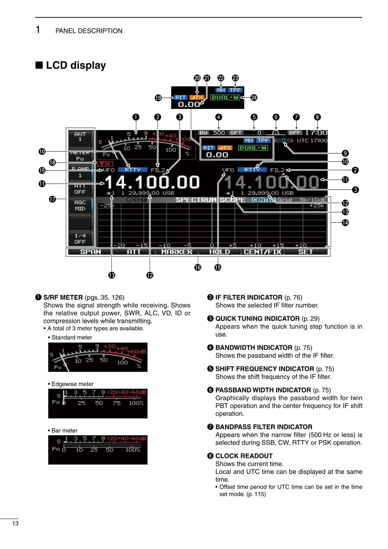
q S/RF METER (pgs. 35, 126) Shows the sgnal strength whle recevng. Shows
the relatve output power, SWR, ALC, VD, ID or compresson levels whle transmttng.
• A total of 3 meter types are avalable.
• Standard meter
• Edgewise meter
• Bar meter
w IF FILTER INDICATOR (p. 76) Shows the selected IF filter number.
e QUICK TUNING INDICATOR (p. 29) Appears when the quck tunng step functon s n
use.
r BANDWIDTH INDICATOR (p. 75) Shows the passband wdth of the IF filter.
t SHIFT FREQUENCY INDICATOR (p. 75) Shows the shft frequency of the IF filter.
y PASSBAND WIDTH INDICATOR (p. 75) Graphcally dsplays the passband wdth for twn
PBT operaton and the center frequency for IF shft operaton.
u BANDPASS FILTER INDICATOR Appears when the narrow filter (500 Hz or less) s
selected durng SSB, CW, RTTY or PSK operaton.
i CLOCK READOUT Shows the current tme. Local and UTC tme can be dsplayed at the same
tme. • Offset tme perod for UTC tme can be set n the tme
set mode. (p. 115)
13
1 PANEL DESCRIPTION

o RTTY TUNING INDICATOR Shows the tunng condton n the RTTY mode.
!0 MODE INDICATOR Shows the selected mode.
!1 FREQUENCY READOUTS Shows the operatng frequency. • Gray characters are used for not-selected readout.
!2 MEMORY CHANNEL READOUTS Shows the selected memory channel contents n
VFO mode. Shows the VFO contents n memory mode.
!3 SELECT MEMORY CHANNEL INDICATOR (p. 109) Dsplays the dsplayed memory channel s set as a
select memory channel. The select memory channels are used n the select
scan operaton. The desred memory channels can be assgned to 3 select groups, for fast, convenent scannng.
!4 MULTI-FUNCTION SCREEN Shows the screens for the mult-functon dgtal
meter, spectrum scope, voce recorder, memory lst, scan, memory keyer, RTTY decoder, PSK decoder, IF filter selecton or set modes, etc.
!5 VFO/MEMORY CHANNEL INDICATOR (p. 26) Dsplays the VFO mode or selected memory chan-
nel number.
!6 LCD FUNCTION SWITCH GUIDE Dsplays the functon of the LCD functon swtches
([F-1] to [F-6]).
!7 MULTI-FUNCTION SWITCH GUIDE Dsplays the functon of the mult-functon swtches.
!8 TX INDICATOR “ ” appears whle transmttng. (p. 36) Dsplays the frequency readout for transmt. • “ ” appears durng an operatng frequency s
not n an amateur band. When the band edge warn-ng beep s set to “OFF” (p. 31), “ ” does not appear.
• Appears on the sub band readout when the splt functon s turned ON.
!9 RIT INDICATOR “ ” appears when RIT functon s n use.
@0 ∂TX INDICATOR “ ” appears when ∂TX functon s n use.
@1 RIT/∂TX SHIFT FREQUENCY INDICATOR Shows the shft frequency for the RIT or ∂TX func-
ton.
@2 NOTCH INDICATOR (p. 83) “ ” appears when the manual notch functon
s n use. Ths functon s avalable n the SSB, CW, RTTY, PSK and AM modes.
“ ” appears when the auto notch functon s n use. Ths functon s avalable n the SSB, AM and FM modes.
@3 APF/TPF INDICATOR “ ” appears when the audo peak filter func-
ton s n use. Ths functon s avalable n the CW mode. (p. 39)
“ ” appears when the twn peak filter func-ton s n use. Ths functon s avalable n the RTTY mode. (p. 47)
@4 DUAL WATCH INDICATOR “ ” appears when the dualwatch functon
s n use.
14
1PANEL DESCRIPTION
1
2
3
4
5
6
7
8
9
10
11
12
13
14
15
16
17
18
19
20
21

The followng screens can be selected from the start-up screen. Choose the desred screen usng the followng chart.
Pushng [EXIT/SET] several tmes returns to the start-up screen. See p. 119 for set mode arrangement.
• Spectrum scope screen (p. 65)
• Voice recorder screen* (p. 90)
• RTTY decoder screen (RTTY mode; p. 46)
• Memory keyer screen (CW mode; p. 40)
• Memory list screen (p. 100)
• PSK decoder screen (PSK mode; p. 54)
• Scan screen (VFO mode; p. 107)
• Scan screen (Memory mode; p. 109)
• Set mode menu screen (p. 118)
F-1 F-2 F-3 F-3
F-4
F-5F-2
F-5F-3
F-6F-3
F-4 F-5 F-6
*Previously selected screen, TX or RX memory, is displayed. Push [T/R] (F-6) to switch the screen.
Screen menu arrangement
15
1 PANEL DESCRIPTION
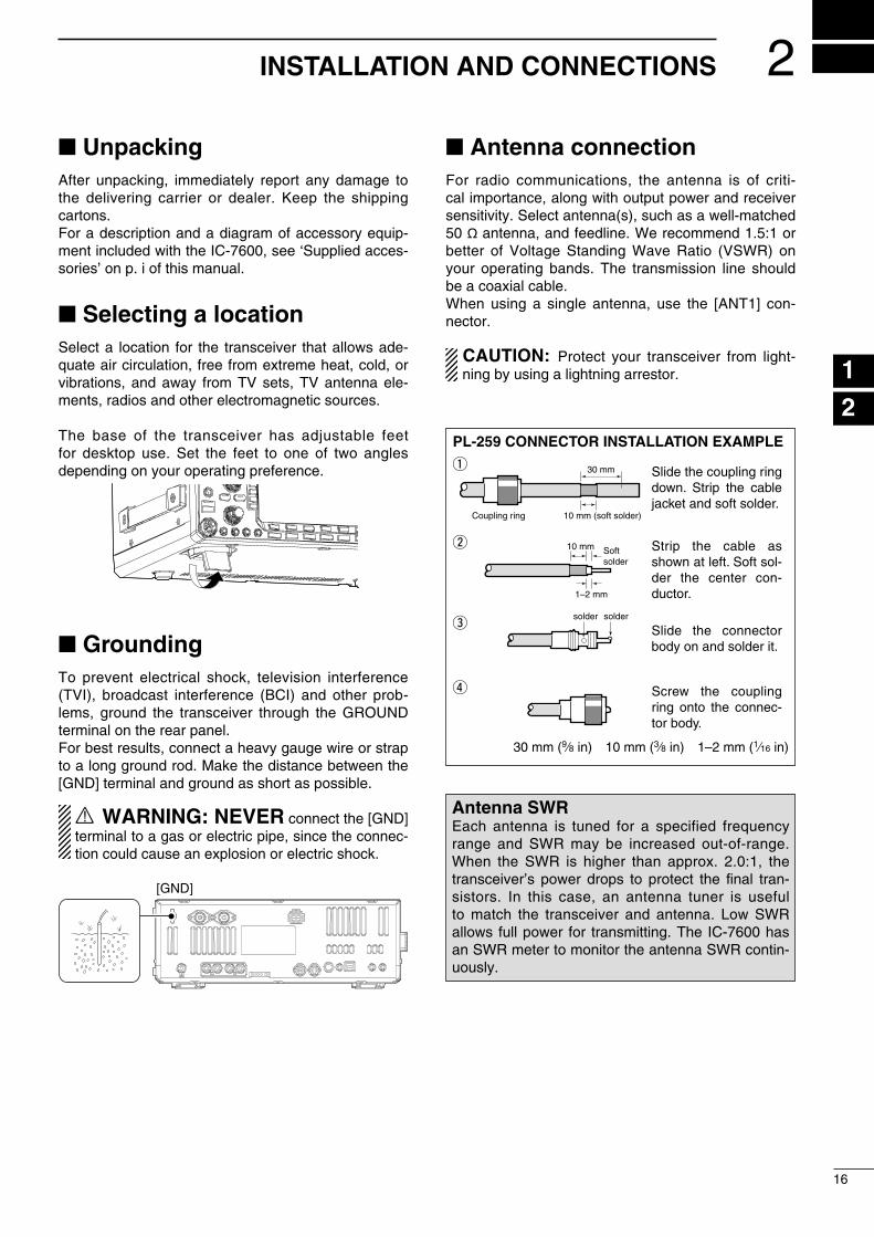
UnpackingAfter unpackng, mmedately report any damage to the delverng carrer or dealer. Keep the shppng cartons.For a descrpton and a dagram of accessory equp-ment ncluded wth the IC-7600, see ‘Suppled acces-sores’ on p. of ths manual.
Selecting a location Select a locaton for the transcever that allows ade-quate ar crculaton, free from extreme heat, cold, or vbratons, and away from TV sets, TV antenna ele-ments, rados and other electromagnetc sources.
The base of the transcever has adjustable feet for desktop use. Set the feet to one of two angles dependng on your operatng preference.
Grounding To prevent electrcal shock, televson nterference (TVI), broadcast nterference (BCI) and other prob-lems, ground the transcever through the GROUND termnal on the rear panel.For best results, connect a heavy gauge wre or strap to a long ground rod. Make the dstance between the [GND] termnal and ground as short as possble.
R WARNING: NEVER connect the [GND] termnal to a gas or electrc ppe, snce the connec-ton could cause an exploson or electrc shock.
[GND]
Antenna connectionFor rado communcatons, the antenna s of crt-cal mportance, along wth output power and recever senstvty. Select antenna(s), such as a well-matched 50 ø antenna, and feedlne. We recommend 1.5:1 or better of Voltage Standng Wave Rato (VSWR) on your operatng bands. The transmsson lne should be a coaxal cable.When usng a sngle antenna, use the [ANT1] con-nector.
CAUTION: Protect your transcever from lght-nng by usng a lghtnng arrestor.
PL-259 CONNECTOR INSTALLATION EXAMPLE
30 mm
10 mm (soft solder)
10 mm
1–2 mm
solder solder
Softsolder
Coupling ring
Slide the coupling ring down. Strip the cable jacket and soft solder.
Slide the connector body on and solder it.
Screw the coupling ring onto the connec-tor body.
Strip the cable as shown at left. Soft sol-der the center con-ductor.
q
w
e
r
30 mm (9⁄8 n) 10 mm (3⁄8 n) 1–2 mm (1⁄16 n)
Antenna SWREach antenna s tuned for a specfed frequency range and SWR may be ncreased out-of-range. When the SWR s hgher than approx. 2.0:1, the transcever’s power drops to protect the fnal tran-sstors. In ths case, an antenna tuner s useful to match the transcever and antenna. Low SWR allows full power for transmttng. The IC-7600 has an SWR meter to montor the antenna SWR contn-uously.
2
16
INSTALLATION AND CONNECTIONS
1
2
3
4
5
6
7
8
9
10
11
12
13
14
15
16
17
18
19
20
21

Required connectionsD Front panel
TWIN-PBT
RIT/ TX
NOTCH CW PITCH
VOICE MEMORY
BAL NR
AF RF/SQL
MIC GAIN RF POWER BK-IN DELAY KEY SPEED
TIMER
PHONES
ELEC-KEY
MIC
AUTOTUNE
GENE F-INP
1.8 3.51 2
14 5 18 6
7 3
24 8 28 9
50 0 ENT
4
7
10
21
CHANGE
TSXFC
SPLIT
DUALWATCH
MAIN/SUB
M.SCOPE VFO/MEMO
MP-W
MW
MP-R
F-6F-5F-4F-3F-2F-1
NRNB
PBT-CLR APF/TPFNOTCH
POWER
RIT CLEARTX
SPEECHLOCKFILTER REC PLAYEXIT/SETSSB CW RTTY/PSK AM/FM
MONITORTRANSMIT TUNER
HF/50MHz TRANSCEIVERLOCKTX RX SPLITCW KEY
A straight key can be used when the internal electronic keyer is turned OFF in keyer set mode. (p. 45)
MICROPHONES (p. 23)
SM-50HM-36
D Rear panel
1 2ANT DC 13.8V
X-VERTERRX-ANT ACC
TUNER
IN OUT ALC SEND KEY1 2 METER REMOTE EXT-SP
ANTENNA 1, 2 (p. 16)
STRAIGHT KEYGROUND (p. 16)
Use the heaviest gauge wire or strap available and make the connection as short as possible.
Grounding prevents electri-cal shocks, TVI and other problems.
DC POWER SUPPLY (p. 20)
PS-126
ANT1 for 1.8–18 MHz bandsANT 2 for 21–28 MHz bands
[Example]:
17
2 INSTALLATION AND CONNECTIONS

Advanced connectionsD Front panel
TWIN-PBT
RIT/ TX
NOTCH CW PITCH
VOICE MEMORY
BAL NR
AF RF/SQL
MIC GAIN RF POWER BK-IN DELAY KEY SPEED
TIMER
PHONES
ELEC-KEY
MIC
AUTOTUNE
GENE F-INP
1.8 3.51 2
14 5 18 6
7 3
24 8 28 9
50 0 ENT
4
7
10
21
CHANGE
TSXFC
SPLIT
DUALWATCH
MAIN/SUB
M.SCOPE VFO/MEMO
MP-W
MW
MP-R
F-6F-5F-4F-3F-2F-1
NRNB
PBT-CLR APF/TPFNOTCH
POWER
RIT CLEARTX
SPEECHLOCKFILTER REC PLAYEXIT/SETSSB CW RTTY/PSK AM/FM
MONITORTRANSMIT TUNER
HF/50MHz TRANSCEIVERLOCKTX RX SPLIT
MIC
USB-MEMORY
The AFSK modulation signal can also be input to [MIC].
KEYBOARDConnect a USB type PC keyboard for direct RTTY/PSK operation, as well as other text edit operations. EXTERNAL KEYPAD
Connect an external keypad for direct voice memory, keyer memory, RTTY TX memory and PSK TX memory controls.
HEADPHONES
To [MIC] connector pin e
To [MIC] connector pin u
1.5k˘±5%
1.5k˘±5%
2.2k˘±5%
4.7k˘±5%
S1(T1/M1/ RT1/PT1)
S2(T2/M2/ RT2/PT2)
S3(T3/M3/ RT3/PT3)
S4(T4/M4/ RT4/PT4)
EXTERNAL KEYPAD
D Rear panel— 1
1 2ANT DC 13.8V
X-VERTERRX-ANT ACC
TUNER
IN OUT ALC SEND KEY1 2 METER REMOTE EXT-SP
RX ANT IN/OUTConnect an external preamp or lowpass filter.
The antenna connector must be selected as “ANT 1/R” or “ANT 2/R.” (p. 3)
ACC SOCKETS 1, 2(pgs. 22, 24)
ANTENNA 1, 2 (p. 112)Connect a linear amplifier, antenna selector, etc.
[X-VERTER]Connect a transverterfor VHF, UHF or otherband use.
[ALC], [SEND] (p. 21)Used for connecting a non-Icom linear amplifier.
EXTERNAL SPEAKER (p. 161)
SP-23(option)
[REMOTE] (p. 151)Used for computer control and transceive operation. The optional CT-17 is required when connect-ing a PC to [REMOTE].AH-4 (p. 20) AH-2b
or long wire
with
18
2INSTALLATION AND CONNECTIONS
1
2
3
4
5
6
7
8
9
10
11
12
13
14
15
16
17
18
19
20
21
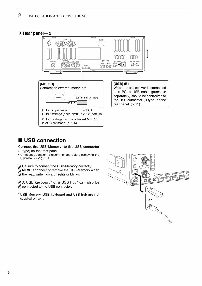
D Rear panel— 21 2ANT DC 13.8V
X-VERTERRX-ANT ACC
TUNER
IN OUT ALC SEND KEY1 2 METER REMOTE EXT-SP
[METER]Connect an external meter, etc.
3.5 (d) mm; 1⁄8" plug
Output impedance : 4.7 køOutput voltage (open circuit) : 2.5 V (default)
Output voltage can be adjusted 0 to 5 V in ACC set mode. (p. 125)
[USB] (B)When the transceiver is connected to a PC, a USB cable (purchase separately) should be connected to the USB connector (B type) on the rear panel. (p. 11)
USB connection Connect the USB-Memory* to the USB connector (A type) on the front panel. • Unmount operaton s recommended before removng the
USB-Memory* (p.142).
Be sure to connect the USB-Memory correctly. NEVER connect or remove the USB-Memory when the read/wrte ndcator lghts or blnks.
A USB keyboard* or a USB hub* can also be connected to the USB connector.
* USB-Memory, USB keyboard and USB hub are not suppled by Icom. or
19
2 INSTALLATION AND CONNECTIONS

Power supply connectionsUse a DC power supply wth a 23 A capacty when operatng the transcever wth AC power. Refer to the dagrams below.
CAUTION: Before connectng the DC power cable, check the followng mportant tems. Make sure:• The [POWER] swtch s OFF.• Output voltage of the power source s 12–15 V
when you use a non-Icom power supply.• DC power cable polarty s correct. Red : Postve + termnal Black : Negatve _ termnal
CONNECTING A DC POWER SUPPLY
A DC power supplyAC outlet
AC cable
30 A fuses
Supplied DC power cable
13.8 V; at least 23 A
_+
Transceiver
To DC powersocket
GND
BlackRed
External antenna tuner connectionCONNECTING THE AH-4
The AH-4 must be connected to [ANT1].
Coaxial cable (from the AH-4)
[ANT1]
Control cable
Transceiver
GND
AH-4
Long wire or optional AH-2b
[TUNER]GND
CONNECTING PS-126 DC POWER SUPPLY
PS-126
DC powercable
To DC power socketTransceiver
AC outlet
AC cable
GND
20
2INSTALLATION AND CONNECTIONS
1
2
3
4
5
6
7
8
9
10
11
12
13
14
15
16
17
18
19
20
21

Linear amplifier connectionsD Connecting the IC-PW1/EURO
EXCITER1 1&2
To anantenna ACC-1
ANT
ANT2ANT1 ACC 2
INPUT1
INPUT2
REMOTE
GND
IC-PW1/EURO
AC outlet(Non-European versions : 100–120/220–240 V European version : 230 V)
Transceiver
REMOTE
Remote control cable (supplied with the IC-PW1/EURO)
ACC cable (supplied with the IC-PW1/EURO)
Be sure to connect the cableto the 7-pin ACC 2 jack.
Coaxial cable(supplied with the IC-PW1/EURO)
Coaxial cable*
*Purchase separately
Connect[INPUT2]if necessary
GND
GND
D Connecting a non-Icom linear amplifier
RF OUTPUT RF INPUT
ALC
SEND
50 øcoaxialcable
Transceiver
ANT1
ALC SENDTo an antenna
Non-Icom linear amplifier
R WARNING: Set the transcever output power and lnear am-
plfier ALC output level after referrng to the lnear amplfier nstructon manual.
The ALC nput level must be n the range 0 V to –4 V. The transcever does not accept postve volt-age. Non-matched ALC and RF power settngs could overheat or damage the lnear amplfier.
The maxmum sgnal level of [SEND] jack s 16 V/ 0.5 A DC wth ntal settng, and 250 V/ 200 mA wth “MOSFET” settng (see p. 125 for detals). Use an external relay unt f your non-Icom lnear ampl-fier requres control voltage and/or current greater than specfied.
21
2 INSTALLATION AND CONNECTIONS

Transverter jack informationWhen 2 to 13.8 V s appled to pn 6 of [ACC 2], the [X-VERTER] connector s actvated for transverter op-eraton and the antenna connectors do not receve or transmt any sgnals.
Whle recevng, the [X-VERTER] connector can be actvated as an nput termnal from an external trans-verter.
Whle transmttng, the [X-VERTER] connector out-puts sgnals of the dsplayed frequency at –20 dBm (22 mV) as sgnals for the external transverter.
FSK and AFSK (SSTV) connectionsTo connect a TNC or scan converter, etc., refer to the dagram below.
D FSK operation— when connecting to [ACC 1]
D AFSK operation
D When connecting to the [USB] connectorConnect a USB cable (purchase separately) between the transcever’s USB connector [USB] (B) on the rear panel and the PC. (p. 19)• Icom HP (http://www.com.co.jp/world/ndex.html) gves the USB drver and the nstallaton gude download servce.
Transverter connector
PC
RS-232C
TNC or scan converter
• When using a PC application
• When using a TNC
1
2
3
4 5
6 78
Rear panel view
Rear panel view
RTTYGND
AF
SEND
RTTY
GND
AF
SEND
RTTY OUTPUT
GND
AUDIO INPUT
PTT
RTTY OUTPUT
GND
AUDIO INPUT
PTT1
2
3
4 5
6 78
Connect to serial port, parallel port, speaker jack, microphone jack and line IN/OUT jack, etc.See the instruction manual of the application for details.
Connect to serial port, parallel port, speaker jack, microphone jack and line IN/OUT jack, etc.See the instruction manual of the application for details.
• When connecting to [ACC 1]
• When connecting to [MIC]
• When using a PC application
• When using a TNC
PC
RS-232CTNC or scan converter
PTT
Audio output
AF inputGND
AFSK output
AF input
GND
PTT*
SQL input†
*When using the VOX function, no need to connect. Refer to the instruction manual of the external equipment (TNC, etc.).†When connecting the squelch line, consult the necessary manual (TNC, etc.).
q
w
er
t
y
u
i
1
2
3
4 5
6 78
z
z
x
x
c
c
v
v*
z
x
c
v
z
x
c
v
b
b
n†
n†
b
n†
Rear panel view
Front panel view
22
2INSTALLATION AND CONNECTIONS
1
2
3
4
5
6
7
8
9
10
11
12
13
14
15
16
17
18
19
20
21
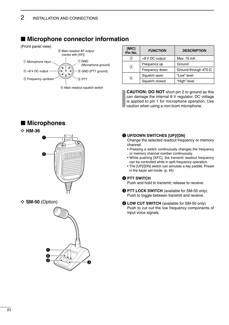
Microphone connector information(Front panel vew)
y GND (PTT ground)
t PTT
r Main readout squelch switch
q Microphone input
w +8 V DC output
e Frequency up/down
i Main readout AF output (varies with [AF])
GND(Microphone ground)
u
[MIC]Pin No.
FUNCTION DESCRIPTION
w +8 V DC output Max. 10 mA
eFrequency up Ground
Frequency down Ground through 470 ˘
rSquelch open “Low” level
Squelch closed “Hgh” level
CAUTION: DO NOT short pn 2 to ground as ths can damage the nternal 8 V regulator. DC voltage s appled to pn 1 for mcrophone operaton. Use cauton when usng a non-Icom mcrophone.
MicrophonesD HM-36
q
w
q
wr
e
D SM-50 (Opton)
q
w
q
wr
e
q UP/DOWN SWITCHES [UP]/[DN] Change the selected readout frequency or memory
channel. • Pressng a swtch contnuously changes the frequency
or memory channel number contnuously. • Whle pushng [XFC], the transmt readout frequency
can be controlled whle n splt frequency operaton. • The [UP]/[DN] swtch can smulate a key paddle. Preset
n the keyer set mode. (p. 45)
w PTT SWITCH Push and hold to transmt; release to receve.
e PTT LOCK SWITCH (avalable for SM-50 only) Push to toggle between transmt and receve.
r LOW CUT SWITCH (avalable for SM-50 only) Push to cut out the low frequency components of
nput voce sgnals.
23
2 INSTALLATION AND CONNECTIONS

Accessory connector informationACC 1 PIN No. NAME DESCRIPTION SPECIFICATIONS
1
2
34 5
6 78
1 RTTY Controls RTTY keyng“Hgh” level“Low” levelOutput current
: More than 2.4 V: Less than 0.6 V: Less than 2 mA
2 GND Connects to ground. Connected n parallel wth ACC 2 pn 2.
3 SENDInput/output pn.Goes to ground when transmttng.When grounded, transmts.
Ground levelOutput currentInput current (Tx)
: –0.5 V to 0.8 V: Less than 20 mA: Less than 200 mA
Connected n parallel wth ACC 2 pn 3.
4 MODModulator nput.Connects to a modulator
Input mpedanceInput level
: 10 k˘: Approx. 100 mV rms
5 AFAF detector output.Fxed, regardless of [AF] poston n default settngs. (see notes below)
Output mpedanceOutput level
: 4.7 k˘: 100–300 mV rms
6 SQLSSquelch output.Goes to ground when squelch opens.
SQL openSQL closed
: Less than 0.3 V/5 mA: More than 6.0 V/100 µA
7 13.8 V 13.8 V output when power s ON.Output current : Max. 1 A
Connected n parallel wth ACC 2 pn 7.
8 ALC ALC voltage nput.Control voltageInput mpedance
: –4 V to 0 V: More than 10 k˘
Connected n parallel wth ACC 2 pn 5.
ACC 2 PIN No. NAME DESCRIPTION SPECIFICATIONS
1
2
34 5
6 7
1 8 V Regulated 8 V output.Output voltageOutput current
: 8.0 V ±0.3 V: Less than 10 mA
2 GND Same as ACC 1 pn 2.
3 SEND Same as ACC 1 pn 3.
4 BANDBand voltage output.(Vares wth amateur band)
Output voltage : 0 to 8.0 V
5 ALC Same as ACC 1 pn 8.
6 TRVActvates [X-VERTER] nput/output when “HIGH” voltage s appled.
Input mpedanceInput voltage
: More than 10 k˘: 2 to 13.8 V
7 13.8 V Same as ACC 1 pn 7.
NOTE: If the CW sdetone level lmt or beep level lmt s n use, the CW sdetone or beep tone de-creases from the fxed level when the [AF] control s rotated above a specfied level. (p. 123)
24
2INSTALLATION AND CONNECTIONS
1
2
3
4
5
6
7
8
9
10
11
12
13
14
15
16
17
18
19
20
21

Before first applying powerBefore frst applyng power, make sure all connec-tons requred for your system are complete by refer-rng to Chapter 2.
After all connectons have been done, set controls and swtches as shown n the fgure below.
TWIN-PBT
RIT/ TX
NOTCH CW PITCH
VOICE MEMORY
BAL NR
AF RF/SQL
MIC GAIN RF POWER BK-IN DELAY KEY SPEED
TIMER
PHONES
ELEC-KEY
MIC
AUTOTUNE
GENE F-INP
1.8 3.51 2
14 5 18 6
7 3
24 8 28 9
50 0 ENT
4
7
10
21
CHANGE
TSXFC
SPLIT
DUALWATCH
MAIN/SUB
M.SCOPE VFO/MEMO
MP-W
MW
MP-R
F-6F-5F-4F-3F-2F-1
NRNB
PBT-CLR APF/TPFNOTCH
POWER
RIT CLEARTX
SPEECHLOCKFILTER REC PLAYEXIT/SETSSB CW RTTY/PSK AM/FM
MONITORTRANSMIT TUNER
HF/50MHz TRANSCEIVERLOCKTX RX SPLIT
[NOTCH]: 12 o’clock
[NR]: Max. CCW
[RF POWER]: Max. CW
[BK-IN DELAY]: 12 o’clock
[KEY SPEED]: 10–12 o’clock
[MIC GAIN]: 12 o’clock
[BAL]: 12 o’clock
[AF]: Max. CCW
[RF/SQL]: 12 o’clock
[CW PITCH]: 12 o’clock
: Max. clockwise: Max. counterclockwise
CWCCW
Applying power (CPU resetting)First applying power:Reset the transcever usng the followng procedure.
Resettng CLEARS all programmed contents n memory channels and returns programmed values n the set mode to default values.
q Make sure the transcever power s OFF.w Whle pushng and holdng [F-INP ENT] and [MW],
push [POWER] to turn power ON. • The CPU s reset. • The CPU start-up takes approx. 5 sec. • The transcever dsplays ts ntal VFO frequences
when resettng s complete.e Change the set mode settngs after resettng, f
desred.
Normal applying power:Push [POWER] to turn power ON, then check the ds-play. When any of ndcators appear, turn them OFF f necessary. (See the approprate page for detals.)
POWER F-INP ENT MW
3
25
BASIC OPERATION
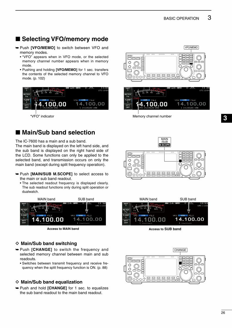
26
3BASIC OPERATION
1
2
3
4
5
6
7
8
9
10
11
12
13
14
15
16
17
18
19
20
21
Selecting VFO/memory mode Push [VFO/MEMO] to swtch between VFO and
memory modes. • “VFO” appears when n VFO mode, or the selected
memory channel number appears when n memory mode.
• Pushng and holdng [VFO/MEMO] for 1 sec. transfers the contents of the selected memory channel to VFO mode. (p. 102)
Main/Sub band selectionThe IC-7600 has a man and a sub band.The man band s dsplayed on the left hand sde, and the sub band s dsplayed on the rght hand sde of the LCD. Some functons can only be appled to the selected band, and transmsson occurs on only the man band (except durng splt frequency operaton).
Push [MAIN/SUB M.SCOPE] to select access to the man or sub band readout.
• The selected readout frequency s dsplayed clearly. The sub readout functons only durng splt operaton or dualwatch.
D Main/Sub band switching Push [CHANGE] to swtch the frequency and
selected memory channel between man and sub readouts.
• Swtches between transmt frequency and receve fre-quency when the splt frequency functon s ON. (p. 88)
D Main/Sub band equalization Push and hold [CHANGE] for 1 sec. to equalzes
the sub band readout to the man band readout.
VFO/MEMO
MAIN/SUB
M.SCOPEM.SCOPE
CHANGE
“VFO” ndcator Memory channel number
Access to SUB band
MAIN band SUB band
Access to MAIN band
MAIN band SUB band
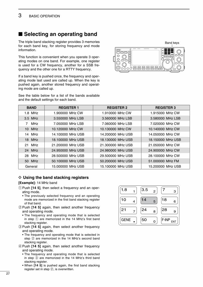
Selecting an operating bandThe trple band stackng regster provdes 3 memores for each band key, for storng frequency and mode nformaton.
Ths functon s convenent when you operate 3 oper-atng modes on one band. For example, one regster s used for a CW frequency, another for a SSB fre-quency and the other one for a RTTY frequency.
If a band key s pushed once, the frequency and oper-atng mode last used are called up. When the key s pushed agan, another stored frequency and operat-ng mode are called up.
See the table below for a lst of the bands avalable and the default settngs for each band.
Band keys
BAND REGISTER 1 REGISTER 2 REGISTER 3
1.8 MHz 1.900000 MHz CW 1.910000 MHz CW 1.915000 MHz CW
3.5 MHz 3.550000 MHz LSB 3.560000 MHz LSB 3.580000 MHz LSB
7 MHz 7.050000 MHz LSB 7.060000 MHz LSB 7.020000 MHz CW
10 MHz 10.120000 MHz CW 10.130000 MHz CW 10.140000 MHz CW
14 MHz 14.100000 MHz USB 14.200000 MHz USB 14.050000 MHz CW
18 MHz 18.100000 MHz USB 18.130000 MHz USB 18.150000 MHz USB
21 MHz 21.200000 MHz USB 21.300000 MHz USB 21.050000 MHz CW
24 MHz 24.950000 MHz USB 24.980000 MHz USB 24.900000 MHz CW
28 MHz 28.500000 MHz USB 29.500000 MHz USB 28.100000 MHz CW
50 MHz 50.100000 MHz USB 50.200000 MHz USB 51.000000 MHz FM
General 15.000000 MHz USB 15.100000 MHz USB 15.200000 MHz USB
D Using the band stacking registers[Example]: 14 MHz band
q Push [14 5], then select a frequency and an oper-atng mode.
• The prevously selected frequency and an operatng mode are memorzed n the frst band stackng regster of that band.
w Push [14 5] agan, then select another frequency and operatng mode.
• The frequency and operatng mode that s selected n step q are memorzed n the 14 MHz’s frst band stackng regster.
e Push [14 5] agan, then select another frequency and operatng mode.
• The frequency and operatng mode that s selected n step w are memorzed n the 14 MHz’s second band stackng regster.
r Push [14 5] agan, then select another frequency and operatng mode.
• The frequency and operatng mode that s selected n step e are memorzed n the 14 MHz’s thrd band stackng regster.
• When [14 5] s pushed agan, the frst band stackng regster set n step w, s overwrtten.
GENE F-INP
1.8 3.51 2
14 5 18 6
7 3
24 8 28 9
50 0 ENT
4
7
10
21
27
3 BASIC OPERATION

Frequency settingThe transcever has several tunng methods for con-venent frequency tunng.
D Tuning with the main dialq Push the desred band key on the keypad 1–3
tmes. • 3 dfferent frequences can be selected on each band
wth the band key. (See prevous page “Usng the band stackng regsters.”)
w Rotate the man dal to set the desred frequency.
If the dal lock functon s actvated, the lock ndca-tor lghts, and the man dal does not functon.In ths case, push and hold [SPEECH/LOCK] for 1 sec. to deactvate the lock functon. (p. 82)When “LOCK/SPEECH” s selected n “[SPEECH/LOCK] Swtch” tem n the Others set mode, push-ng [SPEECH/LOCK] deactvates the lock functon. (see p. 131 for detals)
D Direct frequency entry with the keypad The transcever has a keypad for drect frequency entry as descrbed below.
q Push [F-INP ENT]. • “ ” ndcator appears.w Input the desred frequency. • Push [GENE •] to nput “. (decmal pont)” between the
MHz unts and kHz unts.e Push [F-INP ENT] to set the nput frequency. • To cancel the nput, push [EXIT/SET].
Main dial
Band keys
Keypad
1.8 1 3.5 2F-INP ENT F-INP ENT 10 4 GEN • 50 0 14 5
1.8 1 21 7F-INP ENT F-INP ENT 24 8 GEN • 50 0 3.5 2 14 5
50 0F-INP ENT 50 0 F-INP ENT GEN • 21 7 18 6
10 4F-INP ENT F-INP ENT GEN • 3.5 2 14 5
1.8 1F-INP ENT F-INP ENT GEN •14 5
F-INP ENT F-INP ENT 21 7
[EXAMPLE]14.025 MHz
18.0725 MHz
706 kHz
5.100 MHz
7.000 MHz
21.280 MHz 21.245 MHz
28
3BASIC OPERATION
1
2
3
4
5
6
7
8
9
10
11
12
13
14
15
16
17
18
19
20
21
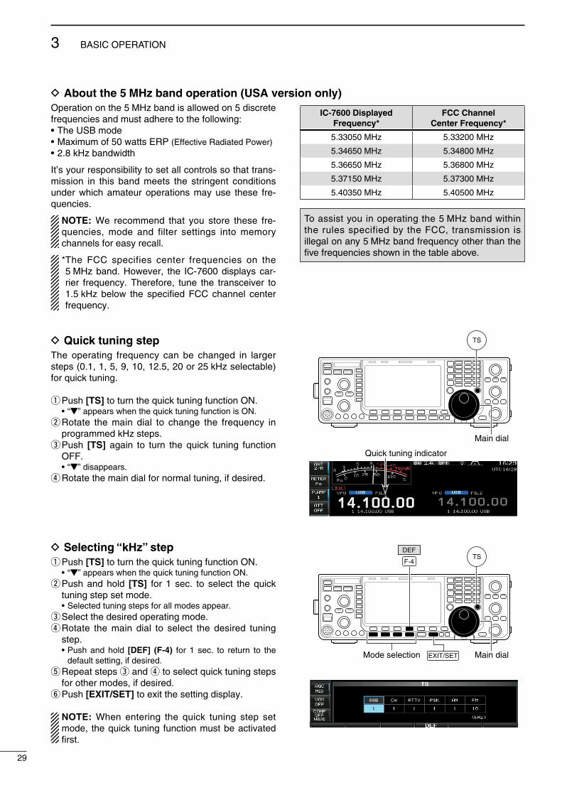
D About the 5 MHz band operation (USA version only)Operaton on the 5 MHz band s allowed on 5 dscrete frequences and must adhere to the followng:• The USB mode• Maxmum of 50 watts ERP (Effectve Radated Power)• 2.8 kHz bandwdth
It’s your responsblty to set all controls so that trans-msson n ths band meets the strngent condtons under whch amateur operatons may use these fre-quences.
NOTE: We recommend that you store these fre-quences, mode and flter settngs nto memory channels for easy recall.
* The FCC specfes center frequences on the 5 MHz band. However, the IC-7600 dsplays car-rer frequency. Therefore, tune the transcever to 1.5 kHz below the specfed FCC channel center frequency.
D Quick tuning stepThe operatng frequency can be changed n larger steps (0.1, 1, 5, 9, 10, 12.5, 20 or 25 kHz selectable) for quck tunng.
q Push [TS] to turn the quck tunng functon ON. • “Z” appears when the quck tunng functon s ON.w Rotate the man dal to change the frequency n
programmed kHz steps.e Push [TS] agan to turn the quck tunng functon
OFF. • “Z” dsappears.r Rotate the man dal for normal tunng, f desred.
D Selecting “kHz” step q Push [TS] to turn the quck tunng functon ON. • “Z” appears when the quck tunng functon ON.w Push and hold [TS] for 1 sec. to select the quck
tunng step set mode. • Selected tunng steps for all modes appear.e Select the desred operatng mode.r Rotate the man dal to select the desred tunng
step. • Push and hold [DEF] (F-4) for 1 sec. to return to the
default settng, f desred.t Repeat steps e and r to select quck tunng steps
for other modes, f desred.y Push [EXIT/SET] to ext the settng dsplay.
NOTE: When enterng the quck tunng step set mode, the quck tunng functon must be actvated frst.
IC-7600 DisplayedFrequency*
FCC ChannelCenter Frequency*
5.33050 MHz 5.33200 MHz
5.34650 MHz 5.34800 MHz
5.36650 MHz 5.36800 MHz
5.37150 MHz 5.37300 MHz
5.40350 MHz 5.40500 MHz
To assst you n operatng the 5 MHz band wthn the rules specfed by the FCC, transmsson s llegal on any 5 MHz band frequency other than the five frequences shown n the table above.
Main dial
TS
Main dial
TS
Mode selection
F-4
EXIT/SET
DEF
Quck tunng ndcator
29
3 BASIC OPERATION
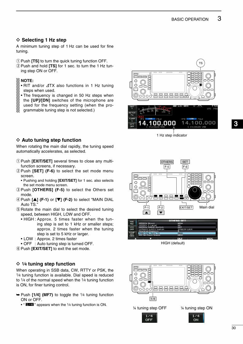
D Selecting 1 Hz stepA mnmum tunng step of 1 Hz can be used for fne tunng.
q Push [TS] to turn the quck tunng functon OFF.w Push and hold [TS] for 1 sec. to turn the 1 Hz tun-
ng step ON or OFF.
NOTE:• RIT and/or ∂TX also functons n 1 Hz tunng
steps when used.• The frequency s changed n 50 Hz steps when
the [UP]/[DN] swtches of the mcrophone are used for the frequency settng (when the pro-grammable tunng step s not selected.)
D Auto tuning step functionWhen rotatng the man dal rapdly, the tunng speed automatcally accelerates, as selected.
q Push [EXIT/SET] several tmes to close any mult-functon screens, f necessary.
w Push [SET] (F-6) to select the set mode menu screen.
• Pushng and holdng [EXIT/SET] for 1 sec. also selects the set mode menu screen.
e Push [OTHERS] (F-5) to select the Others set mode.
r Push [Y] (F-1) or [Z] (F-2) to select “MAIN DIAL Auto TS.”
t Rotate the man dal to select the desred tunng speed, between HIGH, LOW and OFF.
• HIGH : Approx. 5 tmes faster when the tun-ng step s set to 1 kHz or smaller steps; approx. 2 tmes faster when the tunng step s set to 5 kHz or larger.
• LOW : Approx. 2 tmes faster • OFF : Auto tunng step s turned OFF.y Push [EXIT/SET] to ext the set mode.
D 1⁄4 tuning step functionWhen operatng n SSB data, CW, RTTY or PSK, the 1⁄4 tunng functon s avalable. Dal speed s reduced to 1⁄4 of the normal speed when the 1⁄4 tunng functon s ON, for fner tunng control.
Push [1/4] (MF7) to toggle the 1⁄4 tunng functon ON or OFF.
• “ ” appears when the 1⁄4 tunng functon s ON.
TS
Main dialF-1 F-2
F-6
EXIT/SET
SET
F-5
OTHERS
1 ⁄ 4
¼ tuning step OFF ¼ tuning step ON
1 Hz step ndcator
HIGH (default)
30
3BASIC OPERATION
1
2
3
4
5
6
7
8
9
10
11
12
13
14
15
16
17
18
19
20
21
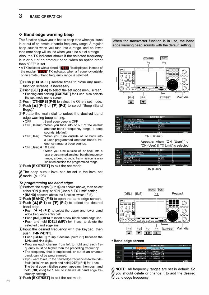
D Band edge warning beepThs functon allows you to hear a beep tone when you tune n or out of an amateur band’s frequency range. A regular beep sounds when you tune nto a range, and an lower tone error beep wll sound when you tune out of a range.Also, the TX ndcator shows f the selected frequency s n or out of an amateur band, when an opton other than “OFF” s set.• A TX ndcator wth a doted, “ ” s dsplayed, nstead of
the regular “ ” TX ndcator, when a frequency outsde of an amateur band frequency range s selected.
q Push [EXIT/SET] several tmes to close any mult-functon screens, f necessary.
w Push [SET] (F-6) to select the set mode menu screen. • Pushng and holdng [EXIT/SET] for 1 sec. also selects
the set mode menu screen.e Push [OTHERS] (F-5) to select the Others set mode.r Push [Y] (F-1) or [Z] (F-2) to select “Beep (Band
Edge).”t Rotate the man dal to select the desred band
edge warnng beep settng. • OFF : Band edge beep s OFF. • ON (Default) : When you tune nto or out of the default
amateur band’s frequency range, a beep sounds. (default)
• ON (User) : When you tune outsde of, or back nto a user programmed amateur band’s fre-quency range, a beep sounds.
• ON (User) & TX Lmt : When you tune outsde of, or back nto a
user programmed amateur band’s frequency range, a beep sounds. Transmsson s also nhbted outsde the programmed range.
y Push [EXIT/SET] to ext the set mode.
The beep output level can be set n the level set mode. (p. 123)
To programming the band edge:q Perform the steps q to t as shown above, then select
ether “ON (User)” or “ON (User) & TX Lmt” settng. • [BAND] appears above the functon swtch (F-5).w Push [BAND] (F-5) to open the band edge screen.e Push [Y] (F-1) or [Z] (F-2) to select the desred
band edge. • Push [Ω ≈] (F-3) to select the upper and lower band
edge frequency entry cell. • Push [INS] (MF6) to nsert a new blank band edge lne. • Push and hold [DEL] (MF7) for 1 sec. to delete the
selected band edge lne.r Input the desred frequency wth the keypad, then
push [F-INP•ENT]. • Push [GENE •] to nput decmal pont (“.”) between the
MHz and kHz dgts. • Program each channel from left to rght and each fre-
quency must be hgher than the precedng frequency. • The frequency that s duplcated, or out of an amateur
band, cannot be programmed. • If you want to return the band edge frequences to ther de-
fault (ntal) value, push and hold [DEF] (F-4) for 1 sec. The band edge ntalze screen appears, then push and
hold [OK] (F-5) for 1 sec. to ntalze all band edge fre-quency settngs.
t Push [EXIT/SET] to ext the set mode.
When the transverter functon s n use, the band edge warnng beep sounds wth the default settng.
Main dialF-1 F-2
F-6
EXIT/SET
SET
F-5
OTHERS
Main dialEXIT/SET
F-5
F-1 F-2 F-3 F-4
DEF
[INS][DEL] KeypadOK/BAND
• Band edge screen
NOTE: All frequency ranges are set n default. So you should delete or change t to add the desred band edge frequency.
ON (Default)
31
3 BASIC OPERATION
ON (User)
Appears when “ON (User)” or “ON (User) & TX Lmt” s selected,

Operating mode selectionSSB (USB/LSB), SSB data (USB data/LSB data), CW, CW reverse (CW-R), RTTY, RTTY reverse (RTTY-R), PSK, PSK reverse (PSK-R), AM, AM data, FM and FM data modes are avalable n the IC-7600. Push the desred mode swtch to select a mode of operaton.
See the dagram as at rght for the order of selecton.
Mcrophone sgnals are muted when data mode s selected dependng on the set mode settngs (p. 124).
• Selecting SSB mode Push [SSB] to select USB or LSB. • USB s selected frst when above 10 MHz; or LSB s
selected frst when below 10 MHz operaton. • After USB or LSB s selected, push [SSB] to toggle
between USB and LSB. • After USB or LSB s selected, push and hold [SSB]
for 1 sec. to select the USB or LSB data mode, respec-tvely.
• After the USB or LSB data mode s selected, push and hold [SSB] for 1 sec. to select data 1, 2 and 3, n sequence.
• In the USB or LSB data mode, push [SSB] to return to the USB or LSB mode, respectvely.
• Selecting CW mode Push [CW] to select CW. • After CW s selected, push [CW] to toggle between the
CW and CW reverse mode.
• Selecting RTTY/PSK mode Push [RTTY/PSK] to select RTTY or PSK. • After RTTY or PSK s selected, push [RTTY/PSK] to
toggle between RTTY and PSK. • After RTTY or PSK s selected, push and hold
[RTTY/PSK] for 1 sec. to toggle between RTTY and RTTY reverse, or, PSK and PSK reverse mode, respectvely.
• Selecting AM/FM mode Push [AM/FM] to select AM or FM. • After AM or FM s selected, push [AM/FM] to toggle
between AM and FM. • After AM or FM s selected, push and hold [AM/FM] for
1 sec. to select AM or FM data mode, respectvely. • After AM or FM data mode s selected, push and
hold [AM/FM] for 1 sec. to select data 1, 2 and 3, n sequence.
• In AM or FM data mode, push [AM/FM] to return to the AM or FM mode, respectvely.
Mode switches
USB
CW
AM
LSB
CW-R
RTTY-R RTTY PSK PSK-R
FM
USB-D1
USB-D2
USB-D3
LSB-D1
LSB-D2
LSB-D3
AM-D1
AM-D2
AM-D3
FM-D1
FM-D2
FM-D3
SSB
CW
RTTY/PSK
AM/FM
: Push mode switch momentary.: Push and hold mode switch for 1 sec.
32
3BASIC OPERATION
1
2
3
4
5
6
7
8
9
10
11
12
13
14
15
16
17
18
19
20
21

Squelch and receive (RF) sensitivityAdjusts the RF gan and squelch threshold level. The squelch removes nose output from the speaker (closed poston) when no sgnal s receved.• The squelch s partcularly effectve for AM and FM. It s
also avalable for other modes.• 12 to 1 o’clock poston s recommended for any settng of
the [RF/SQL] control.• The control can be set as ‘Auto’ (RF gan control n SSB,
CW, RTTY and PSK; squelch control n AM and FM) or squelch control (RF gan s fxed at maxmum) n the Others set mode, as follows. (p. 128)
SET MODE OPERATION
RF+SQL(default)
Can be used n all modes.Functons as nose squelch or S-meter squelch n the FM modes; S-meter squelch only n other modes.
SQLOperates as a squelch control.• RF gan s fixed at maxmum senstvty.
AUTO
Operates as an RF gan control n the SSB, CW, RTTY and PSK modes.• Squelch s fixed open.Operates as a squelch control n the AM and FM modes.• RF gan s fixed at maxmum senstvty.
Adjusting RF gain (Receve senstvty)Normally, [RF/SQL] s set to the 11 o’clock poston.Rotate [RF/SQL] to the 11 o’clock poston for max-mum senstvty.• Rotatng counterclockwse from the maxmum poston
reduces senstvty.• The S-meter ndcates receve senstvty.
Adjusting squelch (Removng non-sgnal nose)Rotate [RF/SQL] clockwse when recevng no sgnal, untl the nose just dsappears.• [RX] ndcator lght goes out.• Rotatng [RF/SQL] past the threshold pont nvokes the S-
meter squelch— ths allows you to set a mnmum sgnal level needed to open the squelch.
[RF/SQL]
• When setting as RF gain/squelch control
Maximum RF gain
S-meter squelch
Noise squelch (FM mode)
Squelch is open.
RF gain adjustablerange
Recommended level
• When functioning as RF gain control (Squelch s fxed open; SSB, CW, RTTY, PSK only)
Minimum RF gain
Adjustablerange
Maximum RF gain
• When functioning as squelch control (RF gan s fxed at maxmum.)
Squelch is open.
S-meter squelch
S-meter squelchthreshold
Noise squelch threshold (FM mode)
Shallow Deep
Noise squelch (FM mode)
Whle rotatng the RF gan control, nose may be heard. Ths comes from the DSP unt and does not ndcate an equpment malfuncton.
33
3 BASIC OPERATION

Volume setting Rotate [AF] control clockwse to ncrease the audo
output level, counterclockwse to decrease t.
Increases
Decreases
Meter Display selectionThe transcever has 6 transmt meter functons for your convenence.
Push [METER] (MF2) several tmes to select the desred meter.
Dsplays the RF output power n % (per-cent).
Dsplays the SWR on the transmsson lne.
Dsplays the ALC level. When the meter movement shows the nput sgnal level exceeds the allowable level, the ALC lmts the RF power. In such cases, reduce the [MIC GAIN] control.
Dsplays the compresson level when the speech compressor s n use.
Dsplays the dran current of the fnal amplfer MOSFETs.
Dsplays the dran termnal voltage of the fnal amplfer MOSFETs.
D Multi-function digital meterThe IC-7600 can dsplay the mult-functon dgtal meter on the LCD dsplay. Ths meter dsplays all transmt parameters smultaneously.
q Push and hold [METER] (MF2) for 1 sec. to turn the mult-functon dgtal meter ON.
w Push [P-HOLD] (F-1) to toggle the peak level hold functon ON.
• “ P-HOLD” appears on the wndow ttle when the peak level hold functon s ON.
e Push and hold [METER] (MF2) for 1 sec., or push [EXIT/SET] to turn the mult-functon dgtal meter OFF.
[AF]
METER
Power level readout SWR readout
ALC level readout Compression levelreadout
ID readout VD readout
F-1
P-HOLD
METER EXIT/SET
“P-HOLD” ndcator
34
3BASIC OPERATION
1
2
3
4
5
6
7
8
9
10
11
12
13
14
15
16
17
18
19
20
21
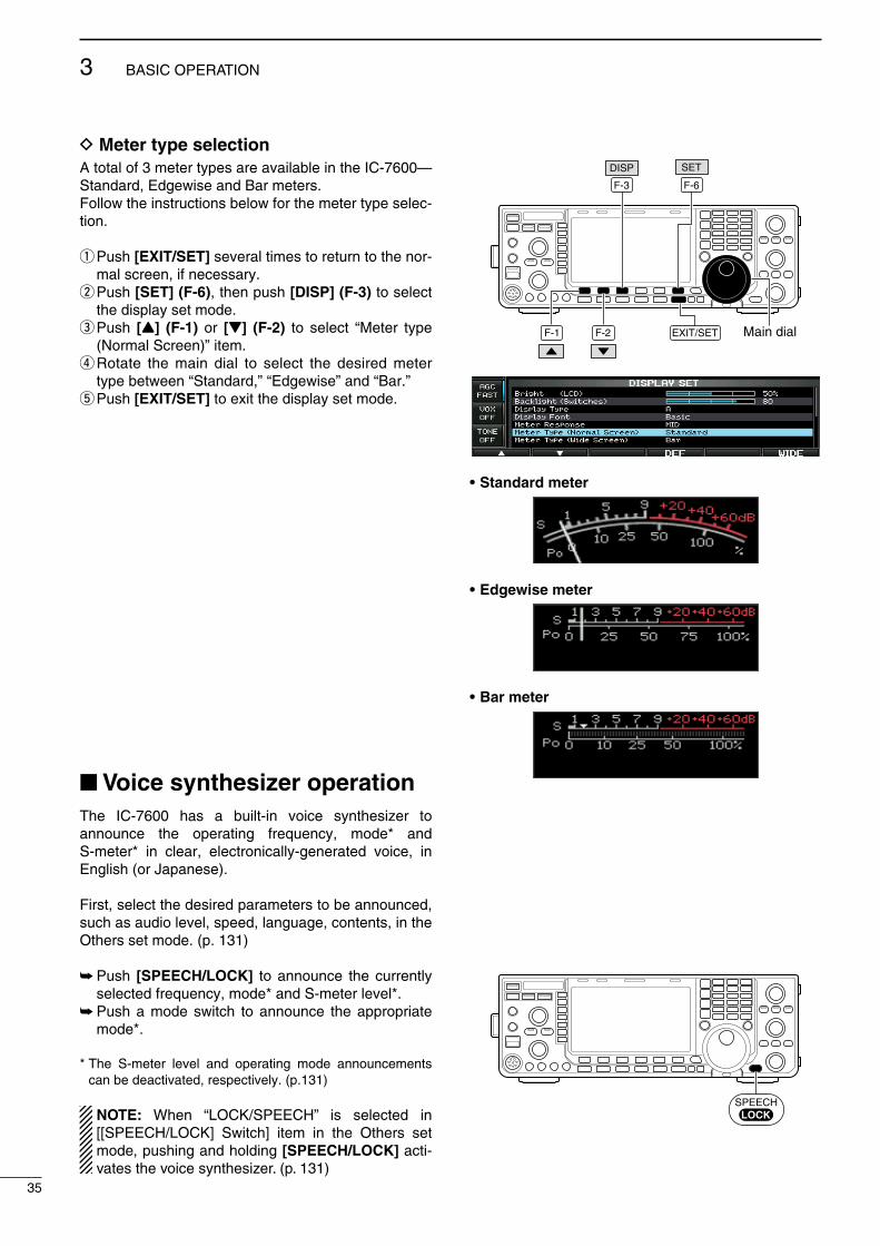
D Meter type selectionA total of 3 meter types are avalable n the IC-7600— Standard, Edgewse and Bar meters. Follow the nstructons below for the meter type selec-ton.
q Push [EXIT/SET] several tmes to return to the nor-mal screen, f necessary.
w Push [SET] (F-6), then push [DISP] (F-3) to select the dsplay set mode.
e Push [Y] (F-1) or [Z] (F-2) to select “Meter type (Normal Screen)” tem.
r Rotate the man dal to select the desred meter type between “Standard,” “Edgewse” and “Bar.”
t Push [EXIT/SET] to ext the dsplay set mode.
Voice synthesizer operationThe IC-7600 has a bult-n voce syntheszer to announce the operatng frequency, mode* and S-meter* n clear, electroncally-generated voce, n Englsh (or Japanese).
Frst, select the desred parameters to be announced, such as audo level, speed, language, contents, n the Others set mode. (p. 131)
Push [SPEECH/LOCK] to announce the currently selected frequency, mode* and S-meter level*.
Push a mode swtch to announce the approprate mode*.
* The S-meter level and operatng mode announcements can be deactvated, respectvely. (p.131)
NOTE: When “LOCK/SPEECH” s selected n [[SPEECH/LOCK] Swtch] tem n the Others set mode, pushng and holdng [SPEECH/LOCK] act-vates the voce syntheszer. (p. 131)
Main dialF-1 F-2
F-6
EXIT/SET
SET
F-3
DISP
• Standard meter
• Edgewise meter
• Bar meter
SPEECHLOCK
35
3 BASIC OPERATION

Basic transmit operation
Before transmitting, monitor your selected operating frequency to make sure transmitting won’t cause interference to other stations on the same frequency. It’s good amateur practice to listen first, and then, even if nothing is heard, ask “Is the frequency in use?” once or twice, before you begin operating on that frequency.
D Transmitting Before transmttng, montor your selected operat-ng frequency to make sure transmttng won’t cause nterference to other statons on the same frequency.
q Push [TRANSMIT] or [PTT] (mcrophone) to trans-mt.
• The [TX] ndcator lghts red. • “ ” appears whle transmttng.w Push [TRANSMIT] agan or release [PTT] (mcro-
phone) to return to receve.
Adjusting the transmit output power Rotate [RF POWER]. • Adjustable range : 2 W to 100 W
(The AM mode: 1 W to 30 W)Increasesmax. 100 W(30 W for AM)
Decreasesmin. 2 W(1 W for AM)
Push
D Microphone gain adjustment Before transmttng, montor your selected operat-ng frequency to make sure transmttng won’t cause nterference to other statons on the same frequency.
q Push [SSB] to select the SSB mode.w Push [METER] (MF2) to select the ALC meter.e Push [PTT] (mcrophone) to transmt. • Talk nto the mcrophone at your normal voce level.r Whle talkng nto the mcrophone, rotate
[MIC GAIN] so that the ALC meter readng doesn’t go outsde the ALC zone. (see at rght)
MIC GAIN
Recommended level for an Icom microphone
Increases
DecreasesPush
t Release [PTT] (mcrophone) to return to receve.
In addton, the transcever can dsplay the mult-func-ton dgtal meter n the LCD, whch dsplays all trans-mt meters smultaneously.
[RF POWER]
TRANSMIT [TX] indicator
[MIC GAIN]
METER
SSB
ALC zone
36
3BASIC OPERATION
1
2
3
4
5
6
7
8
9
10
11
12
13
14
15
16
17
18
19
20
21

D Drive gain adjustmentThe drve gan s actve for all modes, other than the SSB mode wth speech compressor OFF.
Before transmttng, montor your selected operat-ng frequency to make sure transmttng won’t cause nterference to other statons on the same frequency.
q Push [EXIT/SET] several tmes to return to the nor-mal screen, f necessary.
w Push [SET] (F-6), then push [LEVEL] (F-1) to select the level set mode.
e Push [Y] (F-1) or [Z] (F-2) to select “Drve Gan” tem.
r Push [METER] (MF2) to select the ALC meter.t Push [PTT] (mcrophone; SSB wth [COMP] ON,
AM or FM), key down (CW) or push [TRANSMIT] (RTTY or PSK) to transmt.
y Whle talkng nto the mcrophone, keyng down or transmttng, rotate the man dal so that the ALC meter readng s wthn 30% to 50% of the ALC scale. (p. 36)
• Talk nto the mcrophone at your normal voce level.u Release [PTT], stop keyng or push [TRANSMIT]
agan to return to receve.i Push [EXIT/SET] to ext the dsplay set mode.
Main dialF-1 F-2
F-6
EXIT/SET
SET
METERTRANSMIT
LEVEL /
Drive gain range
37
3 BASIC OPERATION

Functions for CW operationD About CW reverse modeCW-R (CW Reverse) mode uses the opposte sde band to receve CW sgnals.Use when nterferng sgnals are near a desred sg-nal and you want to use CW-R to reduce the nterfer-ence.
Durng the CW mode, push [CW] to select the CW or CW-R mode.
D About CW pitch controlThe receved CW audo ptch and CW sdetone can be adjusted to sut your preference (from 300 to 900 Hz; n 5 Hz steps). Ths does not change the operatng frequency.
Rotate [CW PITCH] to sut your preference. • Adjustable from 300 to 900 Hz.
The flter set screen graphcally dsplays the CW ptch operatons. (See at rght.) Push and hold [FILTER] for 1 sec. to access the
flter set screen. • The CW ptch frequency s graphcally changed n
5 Hz steps when the selected IF flter passband wdth s below 500Hz (“ ” appears), or n 25 Hz steps when the selected IF flter passband wdth s above 600Hz (“ ” dsappears).
• Push [EXIT/SET] or push and hold [FILTER] for 1 sec. to return to the prevous screen.
D CW sidetone functionWhen the transcever s n receve (and the break-n functon s OFF— p. 85) you can lsten to the CW sd-etone wthout actually transmttng.
Ths allows you to match your transmt frequency exactly to another staton’s by matchng the audo tone. You can also use the CW sdetone (be sure to turn OFF break-n!) to practce CW sendng.CW sdetone level can be adjusted n the level set mode (p. 122).
q Push [SET] (F-6), then push [LEVEL] (F-1) to select the level set mode.
w Push [Y] (F-1) or [Z] (F-2) to select the “Sde Tone Level” tem.
eRotate the man dal to adjust the sdetone level. • Sdetone level s adjustable wthn 0 to 100 % n 1%
steps.r Push [EXIT/SET] to ext the dsplay set mode.
Matchng the frequency of a transmtted and receved sgnal s called “Zero beat.”
Push
BFO
CW-R mode (USB side)
BFO
Desired signal
CW mode (LSB side)
Interference Desired signalInterference
[CW PITCH]
Lower pitch
Higher pitch
• Filter set screen
CW pitch frequency (e.g. 700 Hz)
Main dialF-1 F-2 F-6 EXIT/SET
SETLEVEL /
4
38
RECEIVE AND TRANSMIT
1
2
3
4
5
6
7
8
9
10
11
12
13
14
15
16
17
18
19
20
21
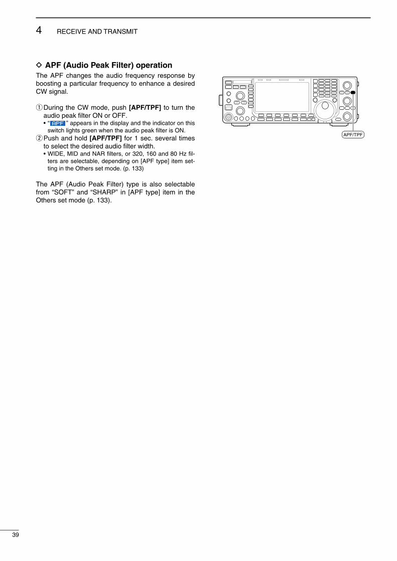
D APF (Audio Peak Filter) operationThe APF changes the audo frequency response by boostng a partcular frequency to enhance a desred CW sgnal.
q Durng the CW mode, push [APF/TPF] to turn the audo peak flter ON or OFF.
• “ ” appears n the dsplay and the ndcator on ths swtch lghts green when the audo peak flter s ON.
w Push and hold [APF/TPF] for 1 sec. several tmes to select the desred audo flter wdth.
• WIDE, MID and NAR flters, or 320, 160 and 80 Hz fl-ters are selectable, dependng on [APF type] tem set-tng n the Others set mode. (p. 133)
The APF (Audo Peak Flter) type s also selectable from “SOFT” and “SHARP” n [APF type] tem n the Others set mode (p. 133).
APF/TPF
39
4 RECEIVE AND TRANSMIT
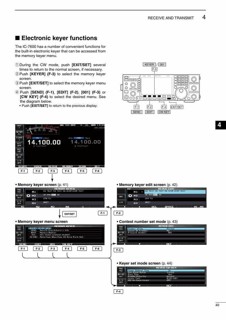
40
4RECEIVE AND TRANSMIT
1
2
3
4
5
6
7
8
9
10
11
12
13
14
15
16
17
18
19
20
21
Electronic keyer functionsThe IC-7600 has a number of convenent functons for the bult-n electronc keyer that can be accessed from the memory keyer menu.
q Durng the CW mode, push [EXIT/SET] several tmes to return to the normal screen, f necessary.
w Push [KEYER] (F-3) to select the memory keyer screen.
e Push [EXIT/SET] to select the memory keyer menu screen.
r Push [SEND] (F-1), [EDIT] (F-2), [001] (F-3) or [CW KEY] (F-4) to select the desred menu. See the dagram below.
• Push [EXIT/SET] to return to the prevous dsplay. F-1 F-2 F-4
F-3
EXIT/SET
CW KEYEDITSEND
001KEYER /
• Memory keyer screen (p. 41)
• Memory keyer menu screen
• Memory keyer edit screen (p. 42)
• Contest number set mode (p. 43)
• Keyer set mode screen (p. 44)
F-1 F-2 F-3 F-4 F-5 F-6
F-1 F-2 F-3 F-4 F-5 F-6
F-1 F-2
F-3
F-4
EXIT/SET

D Memory keyer screenPre-set characters can be sent usng the keyer send menu. Contents of the memory keyer are set usng the edt menu.
• Transmittingq Durng the CW mode operaton, push [KEYER] (F-3)
to select the memory keyer screen.w Push [TRANSMIT] to set the transcever to trans-
mt, or set the break-n functon ON (p. 85).e Push one of the functon keys ([M1] (F-1) to [M4] (F-
4)) to send the contents of the memory keyer. • Push and hold a functon key that s pushed n step q
for 1 sec., or push [REPEAT] (F-6) whle sendng the contents of the memory keyer to send repeatedly; push any functon key to cancel the transmsson.
• “ ” appears whle transmttng repeatedly. • The contest seral number counter counts each tme the
contents are sent. • Push [−1] (F-5) to reduce the contest seral number
count by 1 before sendng the contents of the memory keyer to a staton a second tme.
• “M1”–“M4” are hghlghted whle transmttng. • Set the repeat nterval of the memory keyer to 1–60 sec.
(1 sec. steps). See p. 44 for the keyer set mode.r Push [EXIT/SET] twce to return to the the normal
screen.
For your informationWhen an external keypad or keyboard s connected, the programmed contents, M1 to M4, can be trans-mtted wthout selectng the memory keyer screen.See pgs. 18, 133, 134 for detals.• The programmed contents, M1 to M4, are trans-
mtted once when momentarly pushng one of four swtches on the external keypad that s con-nected to [MIC] connector on the front panel; the programmed contents are transmtted repeatedly when pushng and holdng a swtch.
• The programmed contents, M1 to M4, are trans-mtted once when pushng one of [F1] to [F4] key of the keyboard that s connected to the [USB] (A) connector on the front panel; the programmed con-tents are transmtted repeatedly when pushng a key whle pushng and holdng the [SHIFT] key.
F-3 F-5
EXIT/SET
−1KEYER
TRANSMIT
F-4
M4
F-1
M1—
• Memory keyer screenCount up trigger
Durng transmttng:
Appears while transmitting.
Appears while transmitting repeatedly.
41
4 RECEIVE AND TRANSMIT
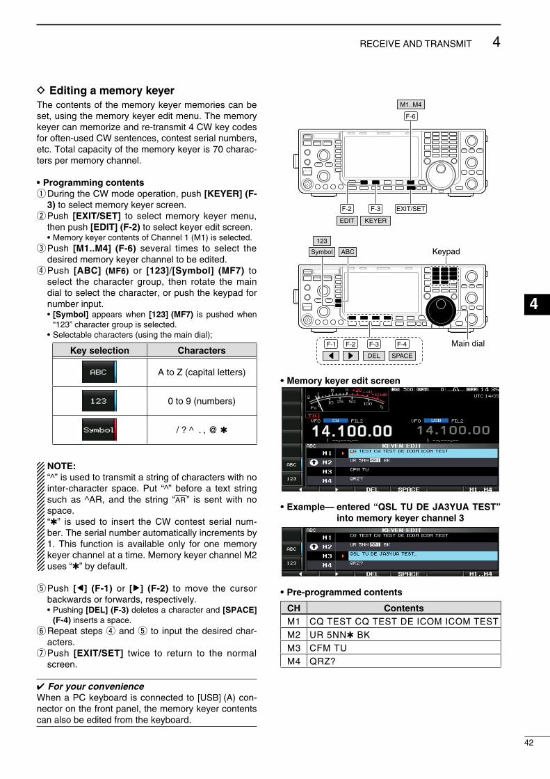
D Editing a memory keyerThe contents of the memory keyer memores can be set, usng the memory keyer edt menu. The memory keyer can memorze and re-transmt 4 CW key codes for often-used CW sentences, contest seral numbers, etc. Total capacty of the memory keyer s 70 charac-ters per memory channel.
• Programming contentsq Durng the CW mode operaton, push [KEYER] (F-
3) to select memory keyer screen.w Push [EXIT/SET] to select memory keyer menu,
then push [EDIT] (F-2) to select keyer edt screen. • Memory keyer contents of Channel 1 (M1) s selected.e Push [M1..M4] (F-6) several tmes to select the
desred memory keyer channel to be edted.r Push [ABC] (MF6) or [123]/[Symbol] (MF7) to
select the character group, then rotate the man dal to select the character, or push the keypad for number nput.
• [Symbol] appears when [123] (MF7) s pushed when “123” character group s selected.
• Selectable characters (usng the man dal);
Key selection Characters
A to Z (captal letters)
0 to 9 (numbers)
/ ? ^ . , @
NOTE:“^” s used to transmt a strng of characters wth no nter-character space. Put “^” before a text strng such as ^AR, and the strng “ar ” s sent wth no space.“” s used to nsert the CW contest seral num-ber. The seral number automatcally ncrements by 1. Ths functon s avalable only for one memory keyer channel at a tme. Memory keyer channel M2 uses “” by default.
t Push [Ω] (F-1) or [≈] (F-2) to move the cursor backwards or forwards, respectvely.
• Pushng [DEL] (F-3) deletes a character and [SPACE] (F-4) nserts a space.
y Repeat steps r and t to nput the desred char-acters.
u Push [EXIT/SET] twce to return to the normal screen.
For your convenienceWhen a PC keyboard s connected to [USB] (A) con-nector on the front panel, the memory keyer contents can also be edted from the keyboard.
F-2
F-6
EXIT/SET
EDIT
F-3
KEYER
M1..M4
F-1 F-2 F-4 Main dial
Symbol ABC
123
F-3
DEL SPACE
Keypad
• Memory keyer edit screen
• Example— entered “QSL TU DE JA3YUA TEST” into memory keyer channel 3
• Pre-programmed contents
CH ContentsM1 CQ TEST CQ TEST DE ICOM ICOM TESTM2 UR 5NN BKM3 CFM TUM4 QRZ?
42
4RECEIVE AND TRANSMIT
1
2
3
4
5
6
7
8
9
10
11
12
13
14
15
16
17
18
19
20
21
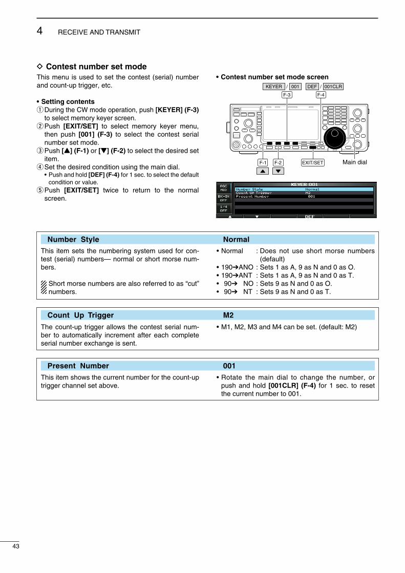
D Contest number set modeThs menu s used to set the contest (seral) number and count-up trgger, etc.
• Setting contentsq Durng the CW mode operaton, push [KEYER] (F-3)
to select memory keyer screen.w Push [EXIT/SET] to select memory keyer menu,
then push [001] (F-3) to select the contest seral number set mode.
e Push [Y] (F-1) or [Z] (F-2) to select the desred set tem.
r Set the desred condton usng the man dal. • Push and hold [DEF] (F-4) for 1 sec. to select the default
condton or value.t Push [EXIT/SET] twce to return to the normal
screen.
• Contest number set mode screen
Main dialF-1 F-2
F-4
EXIT/SET
F-3
KEYER 001/ 001CLR/DEF
Number Style Normal
Ths tem sets the numberng system used for con-test (seral) numbers— normal or short morse num-bers.
Short morse numbers are also referred to as “cut” numbers.
• Normal : Does not use short morse numbers (default)
• 190ANO : Sets 1 as A, 9 as N and 0 as O.• 190ANT : Sets 1 as A, 9 as N and 0 as T.• 90 NO : Sets 9 as N and 0 as O.• 90 NT : Sets 9 as N and 0 as T.
Count Up Trigger M2
The count-up trgger allows the contest seral num-ber to automatcally ncrement after each complete seral number exchange s sent.
• M1, M2, M3 and M4 can be set. (default: M2)
Present Number 001
Ths tem shows the current number for the count-up trgger channel set above.
• Rotate the man dal to change the number, or push and hold [001CLR] (F-4) for 1 sec. to reset the current number to 001.
43
4 RECEIVE AND TRANSMIT
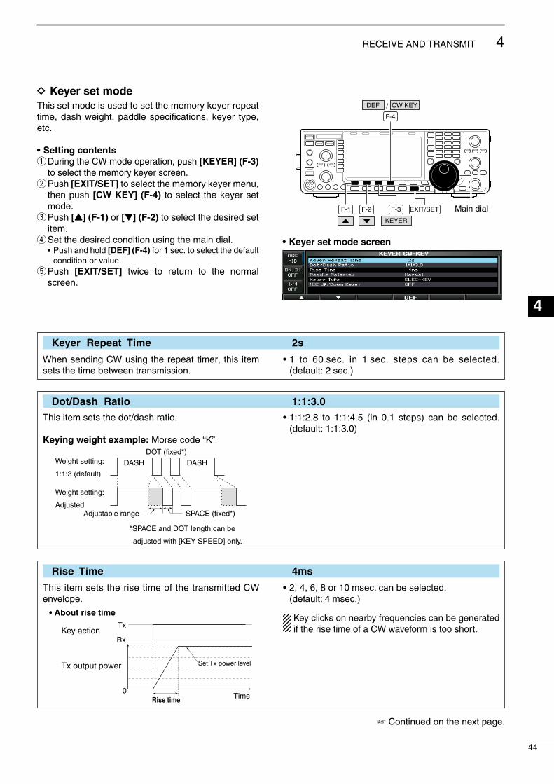
D Keyer set modeThs set mode s used to set the memory keyer repeat tme, dash weght, paddle specficatons, keyer type, etc.
• Setting contentsq Durng the CW mode operaton, push [KEYER] (F-3)
to select the memory keyer screen.w Push [EXIT/SET] to select the memory keyer menu,
then push [CW KEY] (F-4) to select the keyer set mode.
e Push [Y] (F-1) or [Z] (F-2) to select the desred set tem.
r Set the desred condton usng the man dal. • Push and hold [DEF] (F-4) for 1 sec. to select the default
condton or value.t Push [EXIT/SET] twce to return to the normal
screen.
Main dialF-1 F-2 F-3 EXIT/SET
F-4
KEYER
CW KEY/DEF
• Keyer set mode screen
Keyer Repeat Time 2s
When sendng CW usng the repeat tmer, ths tem sets the tme between transmsson.
• 1 to 60 sec. n 1 sec. steps can be selected. (default: 2 sec.)
Dot/Dash Ratio 1:1:3.0
Ths tem sets the dot/dash rato.
Keying weight example: Morse code “K”
DASHWeight setting:
1:1:3 (default)
Weight setting:
Adjusted
DASH
DOT (fixed*)
Adjustable range SPACE (fixed*)
*SPACE and DOT length can be
adjusted with [KEY SPEED] only.
• 1:1:2.8 to 1:1:4.5 (n 0.1 steps) can be selected. (default: 1:1:3.0)
Rise Time 4ms
Ths tem sets the rse tme of the transmtted CW envelope.
Key action
Tx output power
• About rise time
Rise time
Tx
Rx
Set Tx power level
Time0
• 2, 4, 6, 8 or 10 msec. can be selected. (default: 4 msec.)
Key clcks on nearby frequences can be generated f the rse tme of a CW waveform s too short.
Contnued on the next page.
44
4RECEIVE AND TRANSMIT
1
2
3
4
5
6
7
8
9
10
11
12
13
14
15
16
17
18
19
20
21
D Keyer set mode (contnued)
Paddle Polarity Normal
Ths tem sets the paddle dot-dash polarty. • Normal and reverse polarty can be selected.
Keyer Type ELEC-KEY
Ths tem selects the keyer type for the [ELEC-KEY] connector on the front panel.
• Straght key, BUG-KEY and ELEC-KEY can be selected. (default: ELEC-KEY)
MIC Up/Down Keyer OFF
(Mcrophone’s [UP]/[DN] swtches keyer)Ths tem allows you to set the mcrophone [UP]/[DN] swtches to be used as a paddle. (The mcro-phone [UP]/[DN] swtches do not work as a ‘squeeze key.’)
• ON : [UP]/[DN] swtches can be used for CW.• OFF : [UP]/[DN] swtches cannot be used for CW.
NOTE: When “ON” s selected, the frequency and memory channel cannot be changed usng the [UP]/[DN] swtches.
45
4 RECEIVE AND TRANSMIT
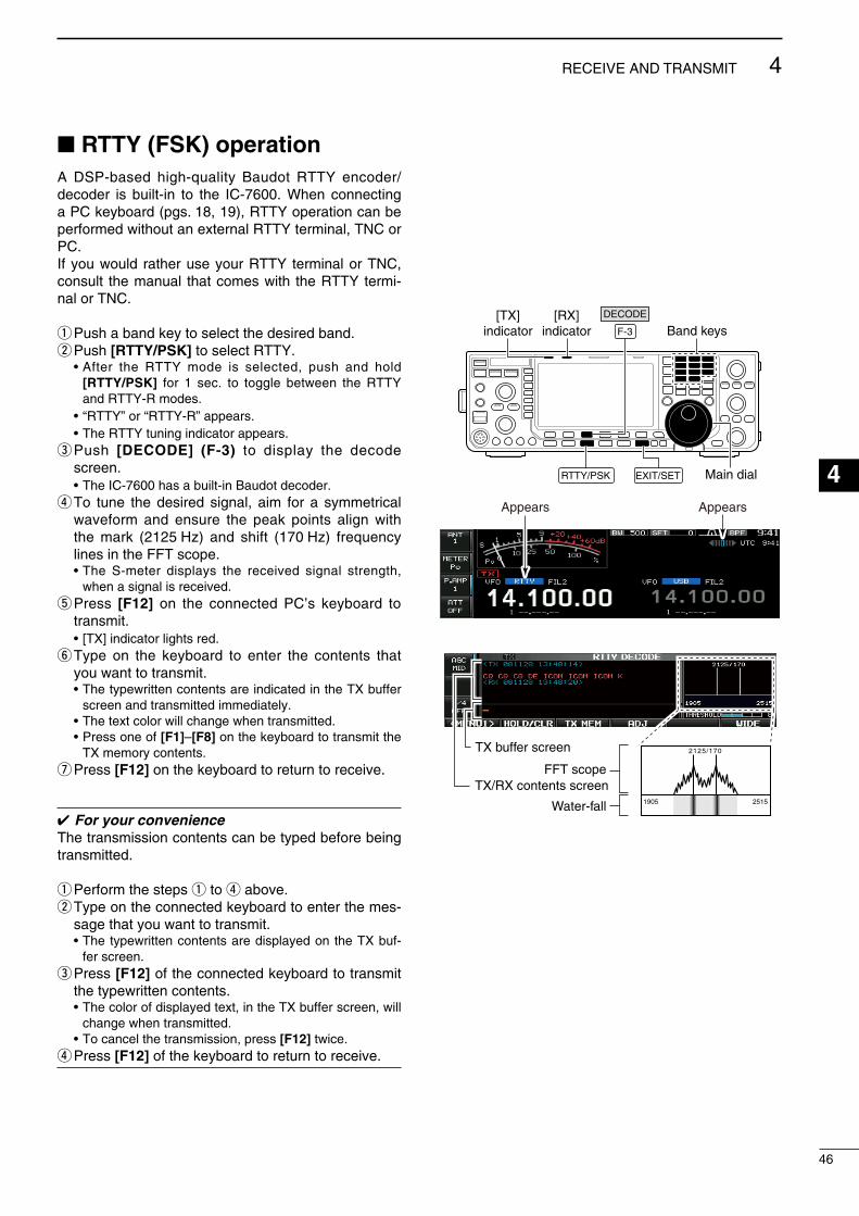
RTTY (FSK) operationA DSP-based hgh-qualty Baudot RTTY encoder/decoder s bult-n to the IC-7600. When connectng a PC keyboard (pgs. 18, 19), RTTY operaton can be performed wthout an external RTTY termnal, TNC or PC.If you would rather use your RTTY termnal or TNC, consult the manual that comes wth the RTTY term-nal or TNC.
q Push a band key to select the desred band.w Push [RTTY/PSK] to select RTTY. • After the RTTY mode s selected, push and hold
[RTTY/PSK] for 1 sec. to toggle between the RTTY and RTTY-R modes.
• “RTTY” or “RTTY-R” appears. • The RTTY tunng ndcator appears.e Push [DECODE] (F-3) to dsplay the decode
screen. • The IC-7600 has a bult-n Baudot decoder.r To tune the desred sgnal, am for a symmetrcal
waveform and ensure the peak ponts algn wth the mark (2125 Hz) and shft (170 Hz) frequency lnes n the FFT scope.
• The S-meter dsplays the receved sgnal strength, when a sgnal s receved.
t Press [F12] on the connected PC’s keyboard to transmt.
• [TX] ndcator lghts red.y Type on the keyboard to enter the contents that
you want to transmt. • The typewrtten contents are ndcated n the TX buffer
screen and transmtted mmedately. • The text color wll change when transmtted. • Press one of [F1]–[F8] on the keyboard to transmt the
TX memory contents.u Press [F12] on the keyboard to return to receve.
For your convenienceThe transmsson contents can be typed before beng transmtted.
q Perform the steps q to r above.w Type on the connected keyboard to enter the mes-
sage that you want to transmt. • The typewrtten contents are dsplayed on the TX buf-
fer screen.e Press [F12] of the connected keyboard to transmt
the typewrtten contents. • The color of dsplayed text, n the TX buffer screen, wll
change when transmtted. • To cancel the transmsson, press [F12] twce.r Press [F12] of the keyboard to return to receve.
Main dialEXIT/SET
F-3
[TX]indicator
[RX]indicator Band keys
RTTY/PSK
DECODE
AppearsAppears
2125/170
1905 2515
FFT scope
TX buffer screen
TX/RX contents screen
Water-fall
46
4RECEIVE AND TRANSMIT
1
2
3
4
5
6
7
8
9
10
11
12
13
14
15
16
17
18
19
20
21

D About RTTY reverse modeReceved characters are occasonally garbled when the receved sgnal s reversed between Mark and Space tones. Ths reversal can be caused by ncor-rect TNC connectons, settng, commands, etc.
To receve a reversed RTTY sgnals correctly, select the RTTY-R (RTTY Reverse) mode.
Durng the RTTY mode, push and hold [RTTY/PSK] for 1 sec. to select the RTTY-R mode.
• Check the receved sgnal.
D Twin peak filterThe twn peak flter changes the audo frequency response by boostng the mark and space frequen-ces (2125 and 2295 Hz) for better recepton of RTTY sgnals.
Durng the RTTY mode, push [APF/TPF] to turn the twn peak flter ON or OFF.
• “ ” appears n the LCD and the ndcator on ths swtch lghts green whle the flter s n use.
NOTE: When the twn peak flter s n use, the receved audo output may ncrease. Ths s a nor-mal, not a malfuncton.
Normal Reverse
Space Mark BFO Space MarkBFO
170 Hz 2125 Hz 170 Hz2125 Hz
APF/TPF
47
4 RECEIVE AND TRANSMIT

D Functions of the RTTY decoder displayq Push a band key to select the desred band.w Push [RTTY/PSK] to select RTTY. • After RTTY s selected, push and hold [RTTY/PSK]
for 1 sec. to toggle between the RTTY and RTTY-R modes.
• “RTTY” or “RTTY-R” appears.e Push [DECODE] (F-3) to dsplay the decode
screen. • When tuned nto an RTTY sgnal, decoded characters
are dsplayed n the RX contents screen.r Push [HOLD/CLR] (F-2) to freeze the current
screen. • “ ” appears whle the functon s n use. • Push [HOLD/CLR] (F-2) agan to cancel the functon.t Push and hold [HOLD/CLR] (F-2) for 1 sec. to
clear the dsplayed characters. • The “ ” ndcator dsappears at the same tme as
the dsplayed characters are cleared. (The hold functon s cancelled.)
y Push [WIDE] (F-6) to toggle the RTTY decode screen sze between normal and wde.
• The S/RF meter type durng wde screen dsplay can be selected n the dsplay set mode. (p. 129)
u Push [EXIT/SET] to close the RTTY decode screen.
D Setting the decoder threshold levelAdjust the RTTY decoder threshold level f some characters are dsplayed when no sgnal s receved.
q Select the RTTY decode screen as descrbed above.
w Push [ADJ] (F-4) to select the threshold level set-tng condton.
e Rotate the man dal to adjust the RTTY decoder threshold level.
• Push and hold [DEF] (F-5) for 1 sec. to select the default settng.
r Push [ADJ] (F-4) to ext from the threshold level settng condton.
The UnShft On Space (USOS) functon and new lne code can be set n the RTTY set mode. (p. 51)
EXIT/SET
F-3 F-6 Band keys
F-2 RTTY/PSK
DECODE
HOLD/CLR
WIDE
• RTTY Decode screen (Normal)
• RTTY Decode screen (Wide)
Main dialF-4 F-5
DEFADJ
Threshold level indication bar
48
4RECEIVE AND TRANSMIT
1
2
3
4
5
6
7
8
9
10
11
12
13
14
15
16
17
18
19
20
21
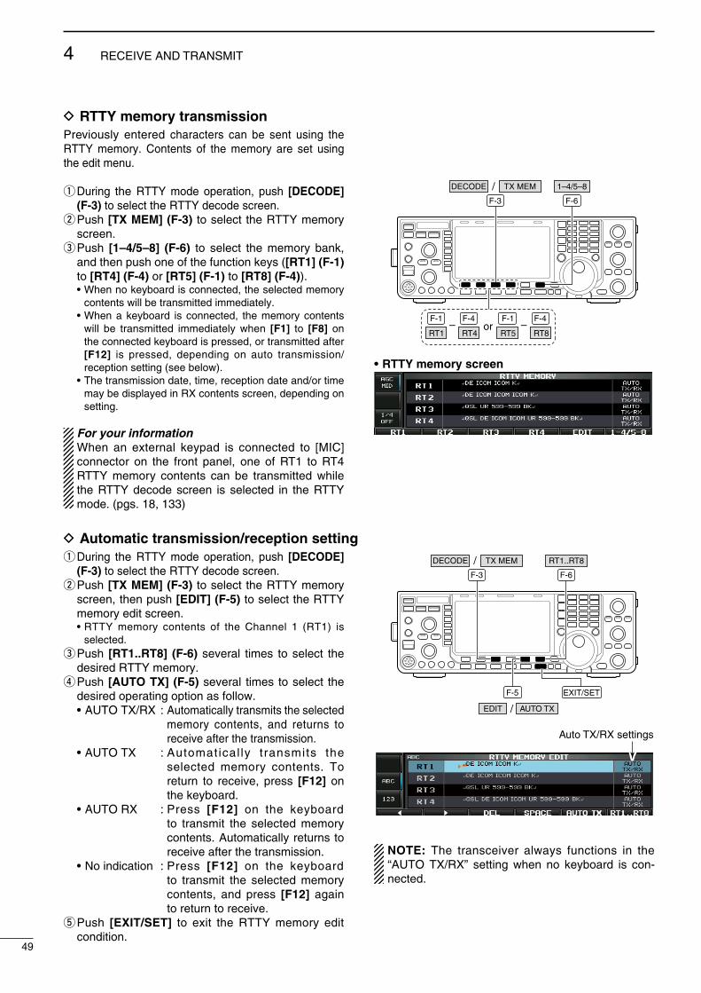
D RTTY memory transmissionPrevously entered characters can be sent usng the RTTY memory. Contents of the memory are set usng the edt menu.
q Durng the RTTY mode operaton, push [DECODE] (F-3) to select the RTTY decode screen.
w Push [TX MEM] (F-3) to select the RTTY memory screen.
e Push [1–4/5–8] (F-6) to select the memory bank, and then push one of the functon keys ([RT1] (F-1) to [RT4] (F-4) or [RT5] (F-1) to [RT8] (F-4)).
• When no keyboard s connected, the selected memory contents wll be transmtted mmedately.
• When a keyboard s connected, the memory contents wll be transmtted mmedately when [F1] to [F8] on the connected keyboard s pressed, or transmtted after [F12] s pressed, dependng on auto transmsson/recepton settng (see below).
• The transmsson date, tme, recepton date and/or tme may be dsplayed n RX contents screen, dependng on settng.
For your information When an external keypad s connected to [MIC]
connector on the front panel, one of RT1 to RT4 RTTY memory contents can be transmtted whle the RTTY decode screen s selected n the RTTY mode. (pgs. 18, 133)
or
F-3 F-6
–F-1 F-4
RT1 RT4–
F-1 F-4
RT5 RT8
/DECODE TX MEM 1–4/5–8
• RTTY memory screen
D Automatic transmission/reception settingq Durng the RTTY mode operaton, push [DECODE]
(F-3) to select the RTTY decode screen.w Push [TX MEM] (F-3) to select the RTTY memory
screen, then push [EDIT] (F-5) to select the RTTY memory edt screen.
• RTTY memory contents of the Channel 1 (RT1) s selected.
e Push [RT1..RT8] (F-6) several tmes to select the desred RTTY memory.
r Push [AUTO TX] (F-5) several tmes to select the desred operatng opton as follow.
• AUTO TX/RX : Automatcally transmts the selected memory contents, and returns to receve after the transmsson.
• AUTO TX : Automatcal ly transmts the selected memory contents. To return to receve, press [F12] on the keyboard.
• AUTO RX : Press [F12] on the keyboard to transmt the selected memory contents. Automatcally returns to receve after the transmsson.
• No ndcaton : Press [F12] on the keyboard to transmt the selected memory contents, and press [F12] agan to return to receve.
t Push [EXIT/SET] to ext the RTTY memory edt condton.
EXIT/SET
F-3 F-6
F-5
/DECODE TX MEM
AUTO TXEDIT /
RT1..RT8
Auto TX/RX settings
NOTE: The transcever always functons n the “AUTO TX/RX” settng when no keyboard s con-nected.
49
4 RECEIVE AND TRANSMIT

D Editing RTTY memoryThe contents of the RTTY memores can be set usng the memory edt menu. The memory can store and re-transmt 8 RTTY message for often-used RTTY nformaton. Total capacty of the memory s 70 char-acters per memory channel.
• Programming contentsq Durng the RTTY mode operaton, push [DECODE]
(F-3) to select the RTTY decode screen.w Push [TX MEM] (F-3) to select the RTTY memory
screen, then push [EDIT] (F-5) to select the RTTY memory edt screen.
• RTTY memory contents of Channel 1 (RT1) s selected.e Push [RT1..RT8] (F-6) several tmes to select the
desred RTTY memory channel to be edted.r Push [ABC] (MF6) or [123]/[Symbol] (MF7) to
select the character group, then rotate the man dal to select the character, or push the keypad for number nput.
• [Symbol] (MF7) appears when [123] (MF7) s pushed when “123” character group s selected.
• Selectable characters (usng the man dal);
Key selection Characters
A to Z (captal letters)
0 to 9 (numbers)
! $ & ? " ’ – / . , : ; ( ) ↵
t Push [Ω] (F-1) or [≈] (F-2) to move the cursor backwards or forwards, respectvely.
• Pushng [DEL] (F-3) deletes a character and [SPACE] (F-4) nserts a space.
y Repeat steps r and t to nput the desred char-acters.
u Push [EXIT/SET] to set the contents and ext the RTTY memory edt screen.
For your convenience When a PC keyboard s connected to the [USB]
connector on the front panel, the RTTY memory contents can also be edted from the keyboard.
EXIT/SET
F-3 F-6
F-5
/DECODE TX MEM
EDIT
RT1..RT8
F-1 F-2 F-4 Main dial
Symbol ABC
123
F-3
DEL SPACE
Keypad
• RTTY memory edit screen
• Pre-programmed contents
CH Contents
RT1 ↵DE ICOM ICOM K↵RT2 ↵DE ICOM ICOM ICOM K↵RT3 ↵QSL UR 599–599 BK↵RT4 ↵QSL DE ICOM ICOM UR 599–599 BK↵RT5 ↵73 GL SK↵RT6 ↵CQ CQ CQ DE ICOM ICOM ICOM K↵
RT7↵MY TRANSCEIVER IS IC–7600 & ANTENNA IS A 3–ELEMENT TRIBAND YAGI.↵
RT8↵MY RTTY EQUIPMENT IS INTERNAL FSK UNIT & DEMODULATOR OF THE IC–7600.↵
50
4RECEIVE AND TRANSMIT
1
2
3
4
5
6
7
8
9
10
11
12
13
14
15
16
17
18
19
20
21
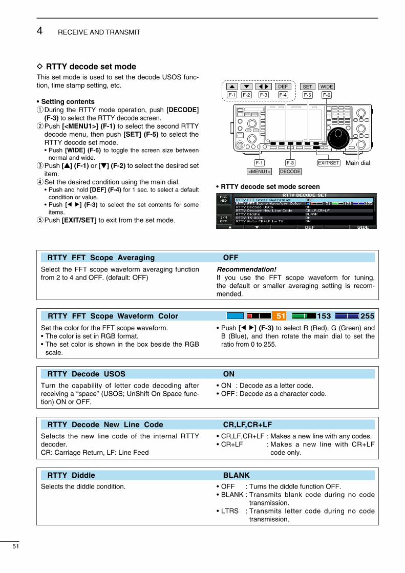
D RTTY decode set modeThs set mode s used to set the decode USOS func-ton, tme stamp settng, etc.
• Setting contentsq Durng the RTTY mode operaton, push [DECODE]
(F-3) to select the RTTY decode screen.w Push [<MENU1>] (F-1) to select the second RTTY
decode menu, then push [SET] (F-5) to select the RTTY decode set mode.
• Push [WIDE] (F-6) to toggle the screen sze between normal and wde.
e Push [Y] (F-1) or [Z] (F-2) to select the desred set tem.
r Set the desred condton usng the man dal. • Push and hold [DEF] (F-4) for 1 sec. to select a default
condton or value. • Push [Ω ≈] (F-3) to select the set contents for some
tems.t Push [EXIT/SET] to ext from the set mode.
F-1 F-2 F-4F-3
DEF
EXIT/SETF-3
F-6
F-1
F-5
Main dialDECODE<MENU1>
SET WIDE
• RTTY decode set mode screen
RTTY FFT Scope Averaging OFF
Select the FFT scope waveform averagng functon from 2 to 4 and OFF. (default: OFF)
Recommendation!If you use the FFT scope waveform for tunng, the default or smaller averagng settng s recom-mended.
RTTY FFT Scope Waveform Color 51 153 255
Set the color for the FFT scope waveform.• The color s set n RGB format.• The set color s shown n the box besde the RGB
scale.
• Push [Ω ≈] (F-3) to select R (Red), G (Green) and B (Blue), and then rotate the man dal to set the rato from 0 to 255.
RTTY Decode USOS ON
Turn the capablty of letter code decodng after recevng a “space” (USOS; UnShft On Space func-ton) ON or OFF.
• ON : Decode as a letter code.• OFF : Decode as a character code.
RTTY Decode New Line Code CR,LF,CR+LF
Selects the new lne code of the nternal RTTY decoder.CR: Carrage Return, LF: Lne Feed
• CR,LF,CR+LF : Makes a new lne wth any codes.• CR+LF : Makes a new lne wth CR+LF
code only.
RTTY Diddle BLANKSelects the dddle condton. • OFF : Turns the dddle functon OFF.
• BLANK : Transmts blank code durng no code transmsson.
• LTRS : Transmts letter code durng no code transmsson.
51
4 RECEIVE AND TRANSMIT

RTTY TX USOS ONExplctly nserts the FIGS character, even though t s not requred by the recevng staton.
• ON : Inserts FIGS.• OFF : Does not nsert FIGS.
RTTY Auto CR+LF by TX ON
Selects the automatc new lne code (CR+LF) trans-msson capablty.
• ON : Transmts CR+LF code once.• OFF : Transmts no CR+LF code.
RTTY Time Stamp ON
Turn the tme stamp (date, transmsson or recepton tme) ndcaton ON or OFF.
• ON : Dsplays the tme stamp.• OFF : No tme stamp ndcaton.
RTTY Time Stamp (Time) Local
Selects the clock ndcaton for tme stamp usage.
NOTE: The tme won’t be dsplayed when “OFF” s selected n “RTTY Tme Stamp,” as explaned above.
• Local : Selects the tme that s set n “Tme (Now).”• UTC* : Selects the tme that s set n “CLOCK2.” * The name of choce may dffer, accord-
ng to “CLOCK2 Name” settng (p. 115). “UTC” s the default name of CLOCK2.
RTTY Time Stamp (Frequency) OFF
Selects the operatng frequency dsplay for tme stamp usage.
NOTE: The frequency won’t be dsplayed when “OFF” s selected n “RTTY Tme Stamp,” as explaned above.
• ON : Dsplays the operatng frequency.• OFF : No operatng frequency dsplay.
RTTY Font Color (Receive) 128 255 128
Set the text color for receved characters.• The color s set n RGB format.• The set color s shown n the box besde the RGB
scale.
• Push [Ω ≈] (F-3) to select R (Red), G (Green) and B (Blue), and then rotate the man dal to set the rato from 0 to 255.
RTTY Font Color (Transmit) 255 106 106Set the text color for transmtted characters.• The color s set n RGB format.• The set color s shown n the box besde the RGB
scale.
• Push [Ω ≈] (F-3) to select R (Red), G (Green) and B (Blue), and then rotate the man dal to set the rato from 0 to 255.
RTTY Font Color (Time Stamp) 0 155 189
Set the text color for tme stamp ndcaton.• The color s set n RGB format.• The set color s shown n the box besde the RGB
scale.
• Push [Ω ≈] (F-3) to select R (Red), G (Green) and B (Blue), and then rotate the man dal to set the rato from 0 to 255.
RTTY Font Color (TX Buffer) 255 255 255
Set the text color n the TX buffer screen.• The color s set n RGB format.• The set color s shown n the box besde the RGB
scale.
• Push [Ω ≈] (F-3) to select R (Red), G (Green) and B (Blue), and then rotate the man dal to set the rato from 0 to 255.
52
4RECEIVE AND TRANSMIT
1
2
3
4
5
6
7
8
9
10
11
12
13
14
15
16
17
18
19
20
21

D Data savingThe contents of the RTTY memory/receved sgnal can be saved nto USB-Memory.
q Durng the RTTY decode screen dsplay, push [<MENU1>] (F-1) to select the RTTY decode sec-ond menu.
w Push [SAVE] (F-4) to select the decode fle save screen.
e Change the followng condtons, f desred. • File name: z Push [EDIT] (F-4) to select the fle name edt
opton. • Push [DIR/FILE] (F-1) several tmes to select the
fle name, f necessary. x Push [ABC] (MF6) or [123]/[Symbol] (MF7)
to select the character group, then rotate the man dal to select the character.
• [ABC] (MF6): A to Z (captal letters); [123] (MF7): 0 to 9 (numerals); [Symbol] (MF7): ! # $ % & ’ ` ^ – ( ) _
_ @ can be selected.
• Push [Ω] (F-1) to move the cursor left, push [≈] (F-2) to move the cursor rght, [DEL] (F-3) delete a character and push [SPACE] (F-4) to nsert a space.
c Push [EXIT/SET] to store the fle name. • File format z Push and hold [SAVE/OPT] (F-5) for 1 sec. to
select the save opton screen. x Rotate the man dal to select the savng for-
mat between Text to HTML. • “Text” s the default settng. • Push and hold [DEF] (F-4) for 1 sec. to select the
default settng. c Push [EXIT/SET] to return to the prevous dsplay. • Saving location z Push [DIR/FILE] (F-1) to select the tree vew
screen. x Select the desred drectory or folder on the
USB-Memory. • Push [Ω ≈] (F-4) to select the upper drectory. • Push [Y] (F-2) or [Z] (F-3) to select folder n the
same drectory. • Push and hold [Ω ≈] (F-4) for 1 sec. to select a
folder n the drectory. • Push [REN] (MF5) to rename the folder. • Push and hold [DEL] (MF6) for 1 sec. to delete
the folder. • Push and hold [MAKE] (MF7) for 1 sec. to mak-
ng a new folder. (Edt the name n the same man-ner as the “• Fle name” above.)
c Push [DIR/FILE] (F-1) twce to select the fle name.
r Push [SAVE/OPT] (F-5). • After savng s completed, automatcally returns to the
RTTY decode second menu.
For your convenience!Two data formats, Text and HTML, are avalable for PC data storage.
The USB-Memory s not suppled by Icom.
F-1 F-2 F-4F-3
DEL SPACE
F-1 F-4 EXIT/SET Main dial
Symbol ABC
123
SAVE EDIT/DIR/FILE<MENU1> /
• Decode file save screen— file name edit
F-4 EXIT/SET Main dialF-5
SAVE/OPTDEF
F-1 F-5
SAVE/OPT
F-4F-2 F-3
DIR/FILE
REN DELMAKE
• Save option screen
When a PC keyboard s connected to the [USB] connec-tor on the front panel, the file name can also be edted from the keyboard. In ths case, a USB hub s requred.
53
4 RECEIVE AND TRANSMIT
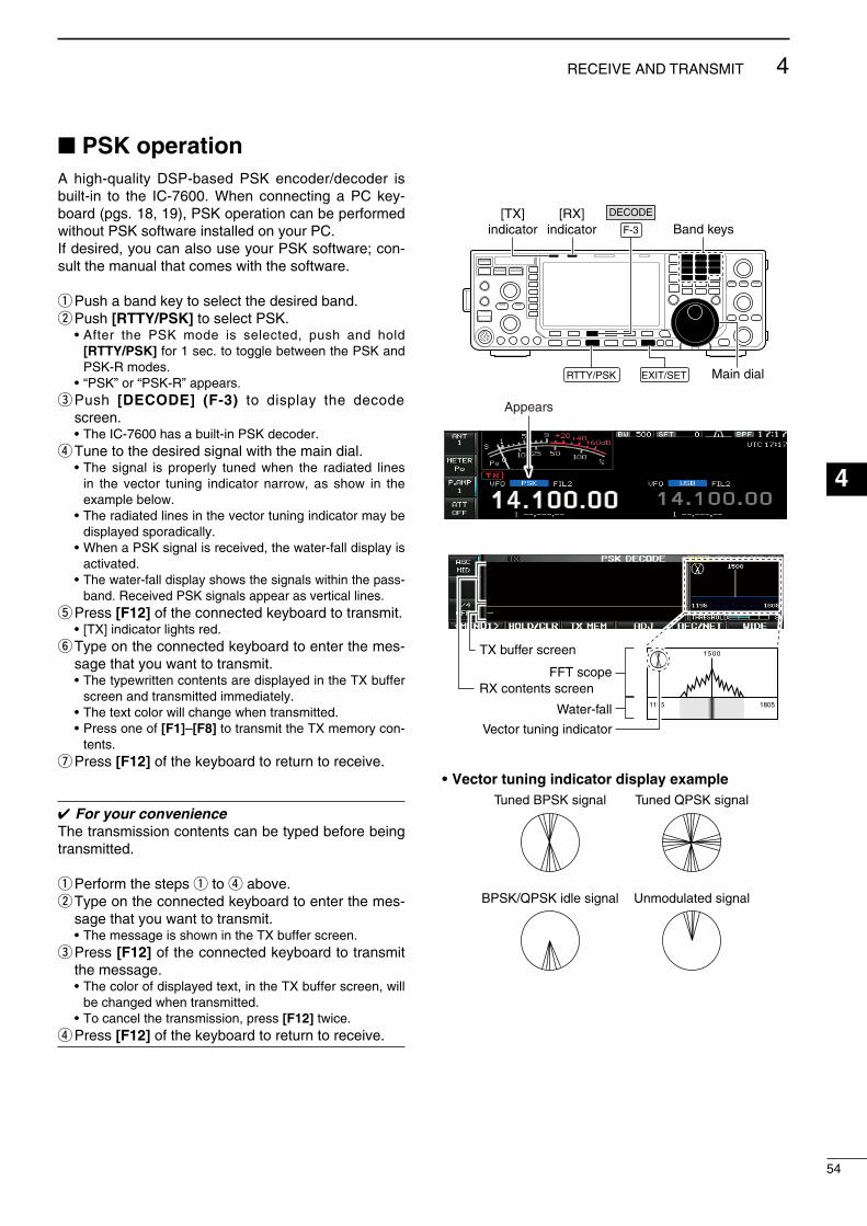
PSK operationA hgh-qualty DSP-based PSK encoder/decoder s bult-n to the IC-7600. When connectng a PC key-board (pgs. 18, 19), PSK operaton can be performed wthout PSK software nstalled on your PC.If desred, you can also use your PSK software; con-sult the manual that comes wth the software.
q Push a band key to select the desred band.w Push [RTTY/PSK] to select PSK. • After the PSK mode s selected, push and hold
[RTTY/PSK] for 1 sec. to toggle between the PSK and PSK-R modes.
• “PSK” or “PSK-R” appears.e Push [DECODE] (F-3) to dsplay the decode
screen. • The IC-7600 has a bult-n PSK decoder.r Tune to the desred sgnal wth the man dal. • The sgnal s properly tuned when the radated lnes
n the vector tunng ndcator narrow, as show n the example below.
• The radated lnes n the vector tunng ndcator may be dsplayed sporadcally.
• When a PSK sgnal s receved, the water-fall dsplay s actvated.
• The water-fall dsplay shows the sgnals wthn the pass-band. Receved PSK sgnals appear as vertcal lnes.
t Press [F12] of the connected keyboard to transmt. • [TX] ndcator lghts red.y Type on the connected keyboard to enter the mes-
sage that you want to transmt. • The typewrtten contents are dsplayed n the TX buffer
screen and transmtted mmedately. • The text color wll change when transmtted. • Press one of [F1]–[F8] to transmt the TX memory con-
tents.u Press [F12] of the keyboard to return to receve.
For your convenienceThe transmsson contents can be typed before beng transmtted.
q Perform the steps q to r above.w Type on the connected keyboard to enter the mes-
sage that you want to transmt. • The message s shown n the TX buffer screen.e Press [F12] of the connected keyboard to transmt
the message. • The color of dsplayed text, n the TX buffer screen, wll
be changed when transmtted. • To cancel the transmsson, press [F12] twce.r Press [F12] of the keyboard to return to receve.
Main dialEXIT/SET
F-3
[TX]indicator
[RX]indicator Band keys
RTTY/PSK
DECODE
Appears
1500
1195 1805
Vector tuning indicator
FFT scope
TX buffer screen
RX contents screen
Water-fall
• Vector tuning indicator display exampleTuned BPSK signal
BPSK/QPSK idle signal Unmodulated signal
Tuned QPSK signal
54
4RECEIVE AND TRANSMIT
1
2
3
4
5
6
7
8
9
10
11
12
13
14
15
16
17
18
19
20
21
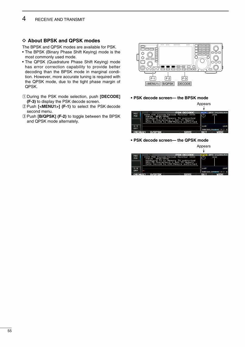
D About BPSK and QPSK modesThe BPSK and QPSK modes are avalable for PSK.• The BPSK (Bnary Phase Shft Keyng) mode s the
most commonly used mode.• The QPSK (Quadrature Phase Shft Keyng) mode
has error correcton capablty to provde better decodng than the BPSK mode n margnal cond-ton. However, more accurate tunng s requred wth the QPSK mode, due to the tght phase margn of QPSK.
q Durng the PSK mode selecton, push [DECODE] (F-3) to dsplay the PSK decode screen.
w Push [<MENU1>] (F-1) to select the PSK decode second menu.
e Push [B/QPSK] (F-2) to toggle between the BPSK and QPSK mode alternately.
F-2 F-3F-1
DECODEB/QPSK<MENU1>
• PSK decode screen— the BPSK modeAppears
• PSK decode screen— the QPSK modeAppears
55
4 RECEIVE AND TRANSMIT
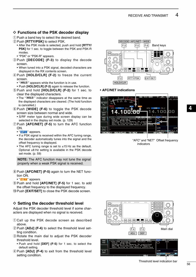
D Functions of the PSK decoder displayq Push a band key to select the desred band.w Push [RTTY/PSK] to select PSK. • After the PSK mode s selected, push and hold [RTTY/
PSK] for 1 sec. to toggle between the PSK and PSK-R modes.
• “PSK” or “PSK-R” appears.e Push [DECODE] (F-3) to dsplay the decode
screen. • When tuned nto a PSK sgnal, decoded characters are
dsplayed n the RX contents screen.r Push [HOLD/CLR] (F-2) to freeze the current
screen. • “ ” appears whle the functon s n use. • Push [HOLD/CLR] (F-2) agan to release the functon.t Push and hold [HOLD/CLR] (F-2) for 1 sec. to
clear the dsplayed characters. • The “ ” ndcator dsappears at the same tme as
the dsplayed characters are cleared. (The hold functon s cancelled.)
y Push [WIDE] (F-6) to toggle the PSK decode screen sze between normal and wde.
• S/RF meter type durng wde screen dsplay can be selected n the dsplay set mode. (p. 129)
u Push [AFC/NET] (F-5) to turn the AFC functon ON.
• “ ” appears. • If a PSK sgnal s receved wthn the AFC tunng range,
the decoder automatcally tunes nto the sgnal and the offset frequency s dsplayed.
• The AFC tunng range s set to ±15 Hz as the default. Optonal ±8 Hz settng s avalable n the PSK decode set mode. (p. 59)
NOTE: The AFC functon may not tune the sgnal properly when a weak PSK sgnal s receved.
i Push [AFC/NET] (F-5) agan to turn the NET func-ton ON.
• “ ” appears.o Push and hold [AFC/NET] (F-5) for 1 sec. to add
the offset frequency to the dsplayed frequency.!0 Push [EXIT/SET] to close the PSK decode screen.
D Setting the decoder threshold level Adjust the PSK decoder threshold level f some char-acters are dsplayed when no sgnal s receved.
q Call up the PSK decode screen as descrbed above.
w Push [ADJ] (F-4) to select the threshold level set-tng condton.
e Rotate the man dal to adjust the PSK decoder threshold level.
• Push and hold [DEF] (F-5) for 1 sec. to select the default settng.
r Push [ADJ] (F-4) to ext from the threshold level settng condton.
EXIT/SET
F-3 F-6F-5 Band keys
F-2 RTTY/PSK
HOLD/CLR
WIDEDECODE AFC/NET
• AFC/NET indications
“AFC” and “NET”indicators
Offset frequency
Main dialF-4 F-5
DEFADJ
Threshold level indication bar56
4RECEIVE AND TRANSMIT
1
2
3
4
5
6
7
8
9
10
11
12
13
14
15
16
17
18
19
20
21

D PSK memory transmissionPrevously entered characters can be sent usng the PSK memory. Contents of the memory are set usng the edt menu.
q Durng the PSK mode operaton, push [DECODE] (F-3) to select the PSK decode screen.
w Push [TX MEM] (F-3) to select the PSK memory screen.
e Push [1–4/5–8] (F-6) to select memory bank then push one of the functon keys ([PT1] (F-1) to [PT4] (F-4) or [PT5] (F-1) to [PT8] (F-4)).
• When no keyboard s connected, the selected memory contents wll be transmtted mmedately.
• When a keyboard s connected, the memory contents wll be transmtted mmedately when [F1] to [F8] on the connected keyboard s pressed, or transmtted after [F12] s pressed, dependng on auto transmsson/recepton settng (see below).
• The transmsson date, tme, recepton date and/or tme may be dsplayed n RX contents screen, dependng on settng.
For your information When an external keypad s connected to [MIC]
connector on the front panel, one of PT1 to PT4 PSK memory contents can be transmtted whle the PSK decode screen s selected n PSK mode. (pgs. 18, 133)
or
F-3 F-6
–F-1 F-4
PT1 PT4–
F-1 F-4
PT5 PT8
/DECODE TX MEM 1–4/5–8
D Automatic transmission/reception settingq Durng the PSK mode operaton, push [DECODE]
(F-3) to select the PSK decode screen.w Push [TX MEM] (F-3) to select the PSK memory
screen, then push [EDIT] (F-5) to select the PSK memory edt screen.
• PSK memory contents of Channel 1 (PT1) s selected.e Push [PT1..PT8] (F-6) several tmes to select the
desred PSK memory.r Push [AUTO TX] (F-5) several tmes to select the
desred operatng opton, as follows. • AUTO TX/RX : Automatcal ly transmts the
selected memory contents, and returns to receve after the trans-msson.
• AUTO TX : Automatcal ly transmts the selected memory contents. To return to receve, press [F12] on the keyboard.
• AUTO RX : Press [F12] on the keyboard to transmt the selected memory contents. Automatcally returns to receve after the transmsson.
• No ndcaton : Press [F12] on the keyboard to transmt the selected memory contents and press [F12] agan to return to receve.
t Push [EXIT/SET] to return to ext from the PSK memory edt condton.
EXIT/SET
F-3 F-6
F-5
/DECODE TX MEM
AUTO TXEDIT /
PT1..PT8
Auto TX/RX settings
NOTE: The transcever always functons n the “AUTO TX/RX” settng when no keyboard s con-nected.
57
4 RECEIVE AND TRANSMIT
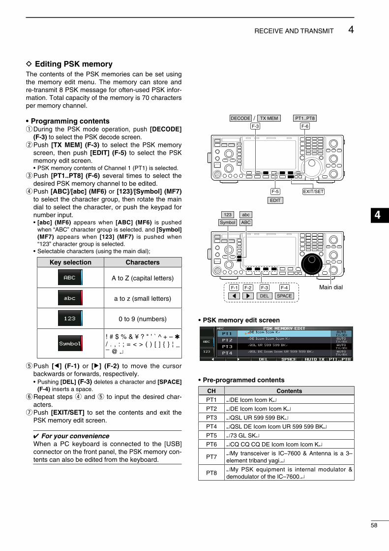
D Editing PSK memoryThe contents of the PSK memores can be set usng the memory edt menu. The memory can store and re-transmt 8 PSK message for often-used PSK nfor-maton. Total capacty of the memory s 70 characters per memory channel.
• Programming contentsq Durng the PSK mode operaton, push [DECODE]
(F-3) to select the PSK decode screen.w Push [TX MEM] (F-3) to select the PSK memory
screen, then push [EDIT] (F-5) to select the PSK memory edt screen.
• PSK memory contents of Channel 1 (PT1) s selected.e Push [PT1..PT8] (F-6) several tmes to select the
desred PSK memory channel to be edted.r Push [ABC]/[abc] (MF6) or [123]/[Symbol] (MF7)
to select the character group, then rotate the man dal to select the character, or push the keypad for number nput.
• [abc] (MF6) appears when [ABC] (MF6) s pushed when “ABC” character group s selected. and [Symbol] (MF7) appears when [123] (MF7) s pushed when “123” character group s selected.
• Selectable characters (usng the man dal);
Key selection Characters
A to Z (captal letters)
a to z (small letters)
0 to 9 (numbers)
! # $ % & ¥ ? " ’ ` ^ + – / . , : ; = < > ( ) [ ] ¦ _ _
@ ↵
t Push [Ω] (F-1) or [≈] (F-2) to move the cursor backwards or forwards, respectvely.
• Pushng [DEL] (F-3) deletes a character and [SPACE] (F-4) nserts a space.
y Repeat steps r and t to nput the desred char-acters.
u Push [EXIT/SET] to set the contents and ext the PSK memory edt screen.
For your convenience When a PC keyboard s connected to the [USB]
connector on the front panel, the PSK memory con-tents can also be edted from the keyboard.
EXIT/SET
F-3 F-6
F-5
/DECODE TX MEM
EDIT
PT1..PT8
F-1 F-2 F-4 Main dial
Symbol ABC
123
F-3
DEL SPACE
abc
• PSK memory edit screen
• Pre-programmed contents
CH Contents
PT1 ↵DE Icom Icom K↵PT2 ↵DE Icom Icom Icom K↵PT3 ↵QSL UR 599 599 BK↵PT4 ↵QSL DE Icom Icom UR 599 599 BK↵PT5 ↵73 GL SK↵PT6 ↵CQ CQ CQ DE Icom Icom Icom K↵
PT7↵My transcever s IC–7600 & Antenna s a 3–element trband yag.↵
PT8↵My PSK equpment s nternal modulator & demodulator of the IC–7600.↵
58
4RECEIVE AND TRANSMIT
1
2
3
4
5
6
7
8
9
10
11
12
13
14
15
16
17
18
19
20
21

D PSK decode set modeThs set mode s used to set the PSK AFC range, tme stamp settng, etc.
• Setting contentsq Durng the PSK mode operaton, push [DECODE]
(F-3) to select the PSK decode screen.w Push [<MENU1>] (F-1) to select the second PSK
decode menu, then push [SET] (F-5) to select the PSK decode set mode.
• Push [WIDE] (F-6) to toggle the screen sze between normal and wde.
e Push [Y] (F-1) or [Z] (F-2) to select the desred set tem.
r Set the desred condton usng the man dal. • Push and hold [DEF] (F-4) for 1 sec. to select a default
condton or value. • Push [Ω ≈] (F-3) to select the set contents for some
tems.t Push [EXIT/SET] to ext from the set mode.
F-1 F-2 F-4F-3
DEF
EXIT/SETF-3
F-6
F-1
F-5
Main dialDECODE<MENU1>
SET WIDE
PSK FFT Scope Averaging OFF
Select the FFT scope waveform averagng functon from 2 to 4 and OFF. (default: OFF)
Recommendation!If you use the FFT scope waveform for tunng, usng the default or smaller averagng settng s recom-mended.
PSK FFT Scope Waveform Color 51 153 255
Set the color for the FFT scope waveform.• The color s set n RGB format.• The set color s shown n the box besde the RGB
scale.
• Push [Ω ≈] (F-3) to select R (Red), G (Green) and B (Blue), and then rotate the man dal to set the rato from 0 to 255.
PSK AFC Range ±15Hz
Select the AFC (Automatc Frequency Control) functon operatng range from ±15 Hz (default) and ±8 Hz.
NOTE: The AFC functon may not tune the sgnal properly when a weak PSK sgnal s receved.
PSK Time Stamp ON
Turn the tme stamp (date, transmsson or recepton tme) dsplay ON or OFF.
• ON : Dsplays the tme stamp.• OFF : No tme stamp dsplay.
PSK Time Stamp (Time) LocalSelects the clock dsplay for tme stamp usage.
NOTE: The tme won’t be dsplayed when “OFF” s selected n “PSK Tme Stamp” as shown above.
• Local : Selects the tme that set n “Tme (Now).”• UTC* : Selects the tme that set n “CLOCK2.” * The name of choce may dffer accordng to
“CLOCK2 Name” settng (p. 115). “UTC” s the default name of CLOCK2.
59
4 RECEIVE AND TRANSMIT

PSK Time Stamp (Frequency) OFFSelects the operatng frequency dsplay for tme stamp usage.NOTE: The frequency won’t be dsplayed when
“OFF” s selected n “PSK Tme Stamp” as shown below left.
• ON : Dsplays the operatng frequency.• OFF : No operatng frequency dsplay.
PSK Font Color (Receive) 128 255 128
Set the text color for receved characters.• The color s set n RGB format.• The set color s shown n the box besde the RGB
scale.
• Push [Ω ≈] (F-3) to select R (Red), G (Green) and B (Blue), and then rotate the man dal to set the rato from 0 to 255.
PSK Font Color (Transmit) 255 106 106
Set the text color for transmtted characters.• The color s set n RGB format.• The set color s shown n the box besde the RGB
scale.
• Push [Ω ≈] (F-3) to select R (Red), G (Green) and B (Blue), and then rotate the man dal to set the rato from 0 to 255.
PSK Font Color (Time Stamp) 0 155 189Set the text color for tme stamp ndcaton.• The color s set n RGB format.• The set color s shown n the box besde the RGB
scale.
• Push [Ω ≈] (F-3) to select R (Red), G (Green) and B (Blue), and then rotate the man dal to set the rato from 0 to 255.
PSK Font Color (TX Buffer) 255 255 255
Set the text color n the TX buffer screen.• The color s set n RGB format.• The set color s shown n the box besde the RGB
scale.
• Push [Ω ≈] (F-3) to select R (Red), G (Green) and B (Blue), and then rotate the man dal to set the rato from 0 to 255.
60
4RECEIVE AND TRANSMIT
1
2
3
4
5
6
7
8
9
10
11
12
13
14
15
16
17
18
19
20
21

D Data savingThe contents of the PSK memory/receved sgnal can be saved nto USB-Memory.
q Durng the PSK decode screen dsplay, push [<MENU1>] (F-1) to select the PSK decode sec-ond menu.
w Push [SAVE] (F-4) to select decode fle save screen.e Change the followng condtons f desred. • File name: z Push [EDIT] (F-4) to select fle name edt con-
dton. • Push [DIR/FILE] (F-1) several tmes to select the
fle name, f necessary. x Push [ABC] (MF6) or [123]/[Symbol] (MF7)
to select the character group, then rotate the man dal to select the character.
• [ABC] (MF6): A to Z (captal letters); [123] (MF7): 0 to 9 (numerals); [Symbol] (MF7): ! # $ % & ’ ` ^ – ( ) _
_ @ can be selected.
• Push [Ω] (F-1) to move the cursor left, push [≈] (F-2) to move the cursor rght, [DEL] (F-3) delete a character and push [SPACE] (F-4) to nsert a space.
c Push [EXIT/SET] to store the fle name. • File format z Push and hold [SAVE/OPT] (F-5) for 1 sec. to
select the save opton screen. x Rotate the man dal to select the savng for-
mat between Text to HTML. • “Text” s the default settng. • Push and hold [DEF] (F-4) for 1 sec. to select the
default settng. c Push [EXIT/SET] to return to the prevous ds-
play. • Saving location z Push [DIR/FILE] (F-1) to select tree vew
screen. x Select the desred drectory or folder on the
USB-Memory. • Push [Ω ≈] (F-4) to select the upper drectory. • Push [Y] (F-2) or [Z] (F-3) to select folder n the
same drectory. • Push and hold [Ω ≈] (F-4) for 1 sec. to select a
folder n the drectory. • Push [REN] (MF5) to rename the folder. • Push and hold [DEL] (MF6) for 1 sec. to delete
the folder. • Push and hold [MAKE] (MF7) for 1 sec. to mak-
ng a new folder. (Edt the name wth the same manner as the “• Fle name” above.)
c Push [DIR/FILE] (F-1) twce to select the fle name.
r Push [SAVE/OPT] (F-5). • After savng s completed, returns to the PSK decode
second menu automatcally.
For your convenience!Two data formats, Text and HTML, are avalable for PC data storage.
The USB-Memory s not suppled by Icom.
F-1 F-2 F-4F-3
DEL SPACE
F-1 F-4 EXIT/SET Main dial
Symbol ABC
123
SAVE EDIT/DIR/FILE<MENU1> /
• Decode file save screen— file name edit
F-4 EXIT/SET Main dialF-5
SAVE/OPTDEF
F-1 F-5
SAVE/OPT
F-4F-2 F-3
DIR/FILE
REN DELMAKE
• Save option screen
When a PC keyboard s connected to the [USB] connec-tor on the front panel, the file name can also be edted from the keyboard. In ths case, a USB hub s requred.
61
4 RECEIVE AND TRANSMIT

Repeater operationA repeater retransmts a receved sgnal on a dffer-ent frequency. When usng a repeater, the transmt frequency s shfted from the receve frequency by an offset frequency. A repeater can be accessed usng splt frequency operaton wth the transmt frequency shfted to the repeater's receve frequency.
For accessng a repeater whch requres an access tone, set the tone frequency n the tone frequency set mode as descrbed below.
q Frst, set the offset frequency for HF and 50 MHz bands n “FM SPLIT Offset (HF)” and “FM SPLIT Offset (50M),” and set the quck splt functon to ON n “Quck SPLIT” n the Others set mode. (p. 129)
w Push [VFO/MEMO] to select the VFO mode.e Push the desred band key, then set the receve fre-
quency (repeater output frequency).r Push [AM/FM] several tmes to select the FM mode.t Push and hold [SPLIT] for 1 sec. to start repeater
operaton. • Repeater tone s turned ON automatcally. • [SPLIT] ndcator lghts and “ ” appears on
the LCD. • The tone encoder functon s turned ON n the FM mode. • Shfted transmt frequency and “TX” appear n the sub
band. • The transmt frequency can be montored whle push-
ng [XFC].y Push and hold [PTT] to transmt; release [PTT] to
receve.u To return to smplex, push [SPLIT] momentarly.
D Repeater access tone frequency settingSome repeaters requre subaudble tones to be accessed. Subaudble tones are supermposed on your normal sgnal and must be set n advance. The transcever has 50 tones from 67.0 Hz to 254.1 Hz.
q Durng FM mode operaton, push and hold [TONE] (MF7) for 1 sec. to select the tone frequency set mode.
w Push [Y] (F-1) or [Z] (F-2) to select REPEATER TONE tem.
e Rotate the man dal to select the desred repeater tone frequency.
• Push and hold [DEF] (F-4) for 1 sec. to select the default settng.
r Push [EXIT/SET] to return to the prevous dsplay.
• Available tone frequencies (unt: Hz)
67.069.371.974.477.079.782.5
85.4088.5091.5094.8097.4100.0103.5
107.2110.9114.8118.8123.0127.3131.8
136.5141.3146.2151.4156.7159.8162.2
165.5167.9171.3173.8177.3179.9183.5
186.2189.9192.8196.6199.5203.5206.5
210.7218.1225.7229.1233.6241.8250.3
254.1
Maindial
[SPLIT]indicator Band keys
AM/FM
SPLIT
VFO/MEMOXFC
Appears Appears
F-4 EXIT/SET Main dialF-2F-1
DEF
TONE
• Tone frequency set mode
62
4RECEIVE AND TRANSMIT
1
2
3
4
5
6
7
8
9
10
11
12
13
14
15
16
17
18
19
20
21

Tone squelch operationThe tone squelch opens only when recevng a sg-nal contanng a matchng subaudble tone. You can slently wat for calls from group members usng the same tone.
q Set the desred frequency band and select the FM mode.
w Push [TONE] (MF7) several tmes to turn the tone squelch functon ON.
• “ ” appearse Push and hold [TONE] (MF7) for 1 sec. to select
the tone frequency set mode.r Push [Y] (F-1) or [Z] (F-2) to select T-SQL TONE
tem.t Rotate the man dal to select the desred tone
squelch frequency. • Push and hold [DEF] (F-4) for 1 sec. to select the
default settng.y Push [EXIT/SET] to return to the prevous dsplay.u When the receved sgnal ncludes a matchng
tone, squelch opens and the sgnal can be heard. • When the receved sgnal’s tone does not match,
tone squelch does not open. However, the S-ndcator shows sgnal strength.
• To open the squelch manually, push [XFC].i Operate the transcever n the normal way.o To cancel the tone squelch, push [TONE] (MF7) to
clear “TSQL.”
• Available tone frequencies (unt: Hz)
67.069.371.974.477.079.782.5
085.4088.5091.5094.8097.4100.0103.5
107.2110.9114.8118.8123.0127.3131.8
136.5141.3146.2151.4156.7159.8162.2
165.5167.9171.3173.8177.3179.9183.5
186.2189.9192.8196.6199.5203.5206.5
210.7218.1225.7229.1233.6241.8250.3
254.1
F-4 EXIT/SET Main dialF-2F-1
DEF
TONEXFC
Appears
• Tone frequency set mode
63
4 RECEIVE AND TRANSMIT

Data mode (AFSK) operationWhen operatng AMTOR or PACKET wth your TNC and/or PC software, consult the manual that comes wth the TNC and/or the software.
q Connect a PC and TNC to the transcever. (p. 22)w Push a band key to select the desred band.e Push [SSB] or [AM/FM] to select the desred oper-
atng mode.r Push and hold [SSB] or [AM/FM] that s pushed n
step e for 1 sec. to turn the data mode ON. • One of “-D1,” “-D2” or “-D3” s addtonally appears. • Durng data mode selecton, push and hold [SSB] or
[AM/FM] for 1 sec. to select data mode 1 (D1), 2 (D2) and 3 (D3) n sequence.
t Rotate the man dal to tune to the desred sgnal and decode t correctly.
• Also use the tunng ndcator of the TNC or software. • Durng the SSB data mode, the 1⁄4 tunng functon can
be used for crtcal tunng.y Operate the PC (software) or TNC to transmt. • When operatng n the SSB data mode, adjust the TNC
output level so that the ALC meter readng doesn’t go outsde the ALC zone.
NOTE: When data mode s selected, the audo nput from the [ACC1] (pn 4) s used for transms-son nstead of the [MIC]’s dependng on the set mode settngs. Modulaton nput connector can be changed n the ACC set mode (p. 124)The fxed condton s used for SSB data transms-son as follows:
• [COMP] : OFF• Tx bandwdth : MID*• Tx Tone (Bass) : 0• Tx Tone (Treble) : 0
* Fxed to the default value (lower: 300, hgher: 2700). (p. 122)
For your informationCarrer frequency s dsplayed when the SSB data mode s selected.See the dagram to the rght for the tone-par example.
Main dial
Band keys
AM/FMSSB
Appears
• Tone-pair example
200 Hz 2125 Hz
2325 Hz
Carrier frequency(displayed frequency)
64
4RECEIVE AND TRANSMIT
1
2
3
4
5
6
7
8
9
10
11
12
13
14
15
16
17
18
19
20
21
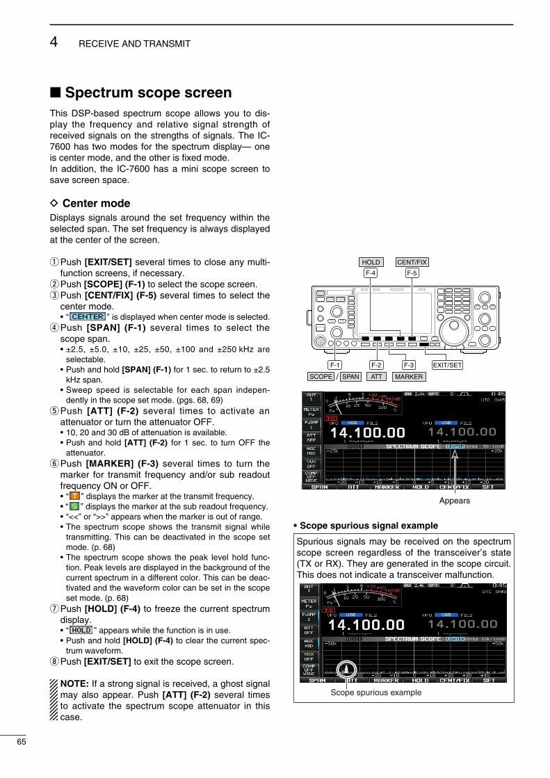
Spectrum scope screenThs DSP-based spectrum scope allows you to ds-play the frequency and relatve sgnal strength of receved sgnals on the strengths of sgnals. The IC-7600 has two modes for the spectrum dsplay— one s center mode, and the other s fxed mode.In addton, the IC-7600 has a mn scope screen to save screen space.
D Center modeDsplays sgnals around the set frequency wthn the selected span. The set frequency s always dsplayed at the center of the screen.
q Push [EXIT/SET] several tmes to close any mult-functon screens, f necessary.
w Push [SCOPE] (F-1) to select the scope screen.e Push [CENT/FIX] (F-5) several tmes to select the
center mode. • “ ” s dsplayed when center mode s selected.r Push [SPAN] (F-1) several tmes to select the
scope span. • ±2.5, ±5.0, ±10, ±25, ±50, ±100 and ±250 kHz are
selectable. • Push and hold [SPAN] (F-1) for 1 sec. to return to ±2.5
kHz span. • Sweep speed s selectable for each span ndepen-
dently n the scope set mode. (pgs. 68, 69)t Push [ATT] (F-2) several tmes to actvate an
attenuator or turn the attenuator OFF. • 10, 20 and 30 dB of attenuaton s avalable. • Push and hold [ATT] (F-2) for 1 sec. to turn OFF the
attenuator.y Push [MARKER] (F-3) several tmes to turn the
marker for transmt frequency and/or sub readout frequency ON or OFF.
• “ ” dsplays the marker at the transmt frequency. • “ ” dsplays the marker at the sub readout frequency. • “<<” or “>>” appears when the marker s out of range. • The spectrum scope shows the transmt sgnal whle
transmttng. Ths can be deactvated n the scope set mode. (p. 68)
• The spectrum scope shows the peak level hold func-ton. Peak levels are dsplayed n the background of the current spectrum n a dfferent color. Ths can be deac-tvated and the waveform color can be set n the scope set mode. (p. 68)
u Push [HOLD] (F-4) to freeze the current spectrum dsplay.
• “ ” appears whle the functon s n use. • Push and hold [HOLD] (F-4) to clear the current spec-
trum waveform.i Push [EXIT/SET] to ext the scope screen.
NOTE: If a strong sgnal s receved, a ghost sgnal may also appear. Push [ATT] (F-2) several tmes to actvate the spectrum scope attenuator n ths case.
F-1 F-2 F-3
F-5F-4
EXIT/SET
/SCOPE SPAN ATT MARKER
HOLD CENT/FIX
• Scope spurious signal example
Spurous sgnals may be receved on the spectrum scope screen regardless of the transcever’s state (TX or RX). They are generated n the scope crcut. Ths does not ndcate a transcever malfuncton.
Scope spurious example
65
4 RECEIVE AND TRANSMIT
Appears

D Fixed modeDsplays sgnals wthn the specfed frequency range. Condtons on the selected frequency band can be observed at a glance when usng ths mode.
q Push [EXIT/SET] several tmes to close any mult-functon screens, f necessary.
w Push [SCOPE] (F-1) to select the scope screen.e Push [CENT/FIX] (F-5) several tmes to select the
fxed mode. • “ ” s dsplayed when fxed mode s selected.r Push [ATT] (F-2) several tmes to actvate an
attenuator or turn the attenuator OFF. • 10, 20 and 30 dB of attenuaton s avalable. • Push and hold [ATT] (F-2) for 1 sec. to turn OFF the
attenuator.t Push [MARKER] (F-3) several tmes to turn the
marker for transmt frequency and/or sub readout frequency ON or OFF.
• “ ” dsplays the marker at the transmt frequency. • “ ” dsplays the marker at the sub readout frequency. • “ ” dsplays the marker at the man readout fre-
quency. (always dsplayed) • “<<” or “>>” appears when the marker s out of range. • The spectrum scope shows the transmt sgnal whle
transmttng. Ths can be deactvated n the scope set mode. (p. 68)
• The spectrum scope shows the peak level hold func-ton. Peak levels are dsplayed n the background of the current spectrum n a dfferent color. Ths can be deac-tvated and the waveform color can be set n the scope set mode. (p. 68)
y Push [HOLD] (F-4) to freeze the current spectrum waveform.
• “ ” appears whle the functon s n use. • Push and hold [HOLD] (F-4) to clear the current spec-
trum waveform.u Push [EXIT/SET] to ext the scope screen.
NOTE: If a strong sgnal s receved, a ghost sgnal may appear. Push [ATT] (F-2) several tmes to actvate the spectrum scope attenuator n ths case.
The scope bandwdth can be specfed for each fre-quency band ndependently n the scope set mode. (pgs. 69 to 71)
F-1 F-2 F-3
F-5F-4
EXIT/SET
/SCOPE SPAN ATT MARKER
HOLD CENT/FIX
66
4RECEIVE AND TRANSMIT
1
2
3
4
5
6
7
8
9
10
11
12
13
14
15
16
17
18
19
20
21
Appears

D Mini scope screen displayThe mn scope screen can be dsplayed wth another screen dsplay, such as the set mode menu, decode screen, memory lst screen, etc. smultaneously.
q Set the scope mode (center or fxed), marker, atten-uator, span, etc. n advance. (pgs. 65, 66)
w Push and hold [MAIN/SUB M.SCOPE] for 1 sec. to select the mn scope ndcaton.
• The S/RF meter type durng mn scope dsplay can be selected n the dsplay set mode (Meter Type (Wde Screen) tem). (p. 126)
D Scope set modeThs set mode s used to set the waveform color, sweepng speed, scope range for fxed mode, etc.
q Durng spectrum scope dsplay ON, push [SET] (F-6) to select the scope set mode screen.
• Push [WIDE] (F-6) to toggle the screen sze between normal and wde.
w Push [Y] (F-1) or [Z] (F-2) to select the desred set tem.
e Set the desred condton usng the man dal. • Push and hold [DEF] (F-4) for 1 sec. to select the default
condton or value. • Push [Ω ≈] (F-3) to select the set contents for some
tems.r Push [EXIT/SET] to ext from the set mode.
MAIN/SUB
M.SCOPEM.SCOPE
F-1 F-2 F-3 F-4
F-6
EXIT/SET Main dial
SET
DEF
67
4 RECEIVE AND TRANSMIT

Scope during Tx (CENTER Type) ON
Turn dsplay of the transmt sgnal ON or OFF. NOTE: Transmt sgnal dsplay s avalable for the center mode only.
Max Hold ONTurn the peak level hold functon ON or OFF.
CENTER Type Display Filter Center
Select the center frequency of the spectrum scope dsplay (center mode only).
• Flter Center : Shows the selected flter’s center frequency at the center.
• Carrer Pont Center : Shows the selected operatng mode
carrer pont frequency at the center.• Carrer Pont Center (Abs. Freq.) : In addton to the carrer pont center
settng above, the actual frequency s dsplayed at the bottom of the scope.
Waveform Color (Current) 217 241 247
Set the waveform color for the currently receved sgnals.
• The color s set n RGB format.• Push [Ω ≈] (F-3) to select R (Red), G (Green) and
B (Blue), and rotate the rato from 0 to 255 range. • The set color s shown n the box besde the RGB
scale.
Waveform Color (Max Hold) 58 110 147
Set the waveform color for the receved sgnals max-mum level.
• The color s set n RGB format.• Push [Ω ≈] (F-3) to select R (Red), G (Green) and
B (Blue), and rotate the rato from 0 to 255 range. • The set color s shown n the box besde the RGB
scale.
Sweep Speed (± 2.5k) MID
Select the sweep speed for the ±2.5 kHz span selec-ton from SLOW, MID and FAST.
NOTE: Sgnals may be dsplayed ncorrectly wth “FAST” settng.
Sweep Speed (± 5k) MID
Select the sweep speed for the ±5 kHz span selec-ton from SLOW, MID and FAST.
NOTE: Sgnals may be dsplayed ncorrectly wth “FAST” settng.
Sweep Speed (± 10k) FAST
Select the sweep speed for the ±10 kHz span selec-ton from SLOW, MID and FAST.
Contnued on the next page.
68
4RECEIVE AND TRANSMIT
1
2
3
4
5
6
7
8
9
10
11
12
13
14
15
16
17
18
19
20
21
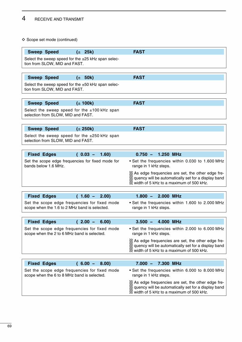
D Scope set mode (contnued)
Sweep Speed (± 25k) FAST
Select the sweep speed for the ±25 kHz span selec-ton from SLOW, MID and FAST.
Sweep Speed (± 50k) FAST
Select the sweep speed for the ±50 kHz span selec-ton from SLOW, MID and FAST.
Sweep Speed (±100k) FAST
Select the sweep speed for the ±100 kHz span selecton from SLOW, MID and FAST.
Sweep Speed (±250k) FAST
Select the sweep speed for the ±250 kHz span selecton from SLOW, MID and FAST.
Fixed Edges ( 0.03 − 1.60) 0.750 − 1.250 MHzSet the scope edge frequences for fixed mode for bands below 1.6 MHz.
• Set the frequences wthn 0.030 to 1.600 MHz range n 1 kHz steps.
As edge frequences are set, the other edge fre-quency wll be automatcally set for a dsplay band wdth of 5 kHz to a maxmum of 500 kHz.
Fixed Edges ( 1.60 − 2.00) 1.800 − 2.000 MHzSet the scope edge frequences for fxed mode scope when the 1.6 to 2 MHz band s selected.
• Set the frequences wthn 1.600 to 2.000 MHz range n 1 kHz steps.
Fixed Edges ( 2.00 − 6.00) 3.500 − 4.000 MHz
Set the scope edge frequences for fxed mode scope when the 2 to 6 MHz band s selected.
• Set the frequences wthn 2.000 to 6.000 MHz range n 1 kHz steps.
As edge frequences are set, the other edge fre-quency wll be automatcally set for a dsplay band wdth of 5 kHz to a maxmum of 500 kHz.
Fixed Edges ( 6.00 − 8.00) 7.000 − 7.300 MHz
Set the scope edge frequences for fxed mode scope when the 6 to 8 MHz band s selected.
• Set the frequences wthn 6.000 to 8.000 MHz range n 1 kHz steps.
As edge frequences are set, the other edge fre-quency wll be automatcally set for a dsplay band wdth of 5 kHz to a maxmum of 500 kHz.
69
4 RECEIVE AND TRANSMIT

Fixed Edges ( 8.00 − 11.00) 10.100 − 10.150 MHz
Set the scope edge frequences for fxed mode scope when the 8 to 11 MHz band s selected.
• Set the frequences wthn 8.000 to 11.000 MHz range n 1 kHz steps.
As edge frequences are set, the other edge fre-quency wll be automatcally set for a dsplay band wdth of 5 kHz to a maxmum of 500 kHz.
Fixed Edges (11.00 − 15.00) 14.000 − 14.350 MHzSet the scope edge frequences for fxed mode scope when the 11 to 15 MHz band s selected.
• Set the frequences wthn 11.000 to 15.000 MHz range n 1 kHz steps.
As edge frequences are set, the other edge fre-quency wll be automatcally set for a dsplay band wdth of 5 kHz to a maxmum of 500 kHz.
Fixed Edges (15.00 − 20.00) 18.068 − 18.168 MHz
Set the scope edge frequences for fxed mode scope when the 15 to 20 MHz band s selected.
• Set the frequences wthn 15.000 to 20.000 MHz range n 1 kHz steps.
As edge frequences are set, the other edge fre-quency wll be automatcally set for a dsplay band wdth of 5 kHz to a maxmum of 500 kHz.
Fixed Edges (20.00 − 22.00) 21.000 − 21.450 MHz
Set the scope edge frequences for fxed mode scope when the 20 to 22 MHz band s selected.
• Set the frequences wthn 20.000 to 22.000 MHz range n 1 kHz steps.
As edge frequences are set, the other edge fre-quency wll be automatcally set for a dsplay band wdth of 5 kHz to a maxmum of 500 kHz.
Fixed Edges (22.00 − 26.00) 24.890 − 24.990 MHz
Set the scope edge frequences for fxed mode scope when the 22 to 26 MHz band s selected.
• Set the frequences wthn 22.000 to 26.000 MHz range n 1 kHz steps.
As edge frequences are set, the other edge fre-quency wll be automatcally set for a dsplay band wdth of 5 kHz to a maxmum of 500 kHz.
Contnued on the next page.
70
4RECEIVE AND TRANSMIT
1
2
3
4
5
6
7
8
9
10
11
12
13
14
15
16
17
18
19
20
21
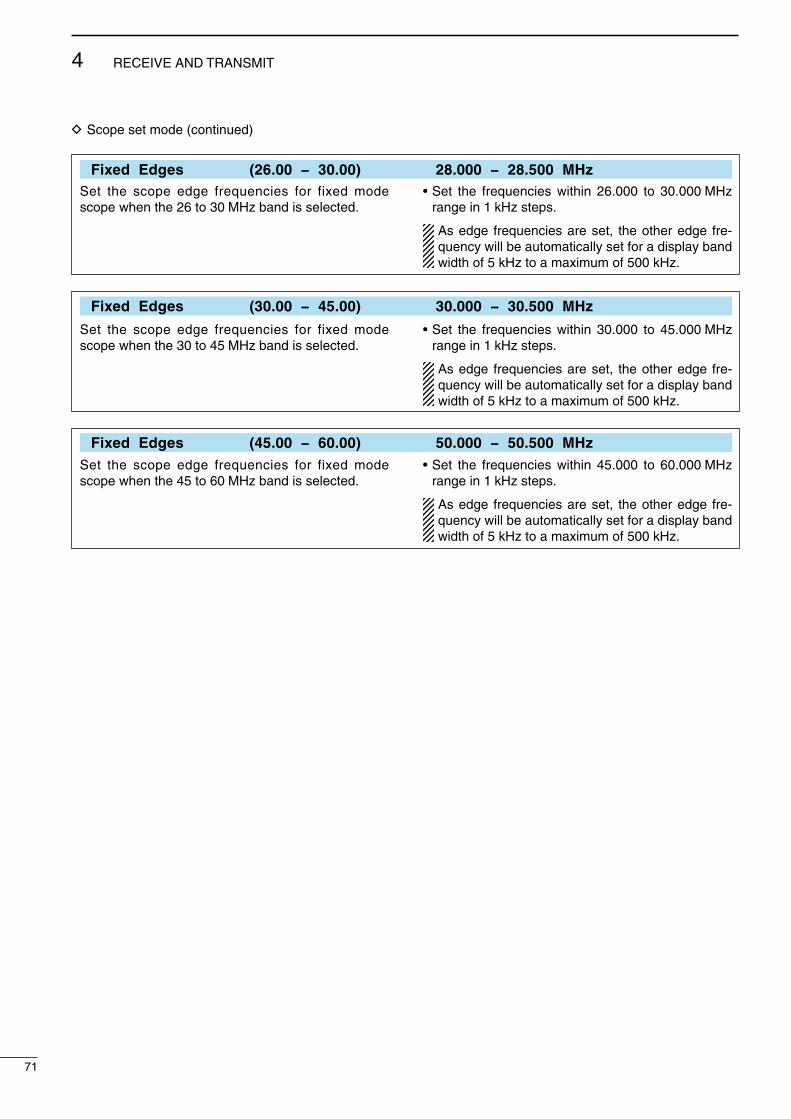
D Scope set mode (contnued)
Fixed Edges (26.00 − 30.00) 28.000 − 28.500 MHzSet the scope edge frequences for fxed mode scope when the 26 to 30 MHz band s selected.
• Set the frequences wthn 26.000 to 30.000 MHz range n 1 kHz steps.
As edge frequences are set, the other edge fre-quency wll be automatcally set for a dsplay band wdth of 5 kHz to a maxmum of 500 kHz.
Fixed Edges (30.00 − 45.00) 30.000 − 30.500 MHz
Set the scope edge frequences for fxed mode scope when the 30 to 45 MHz band s selected.
• Set the frequences wthn 30.000 to 45.000 MHz range n 1 kHz steps.
As edge frequences are set, the other edge fre-quency wll be automatcally set for a dsplay band wdth of 5 kHz to a maxmum of 500 kHz.
Fixed Edges (45.00 − 60.00) 50.000 − 50.500 MHzSet the scope edge frequences for fxed mode scope when the 45 to 60 MHz band s selected.
• Set the frequences wthn 45.000 to 60.000 MHz range n 1 kHz steps.
As edge frequences are set, the other edge fre-quency wll be automatcally set for a dsplay band wdth of 5 kHz to a maxmum of 500 kHz.
71
4 RECEIVE AND TRANSMIT
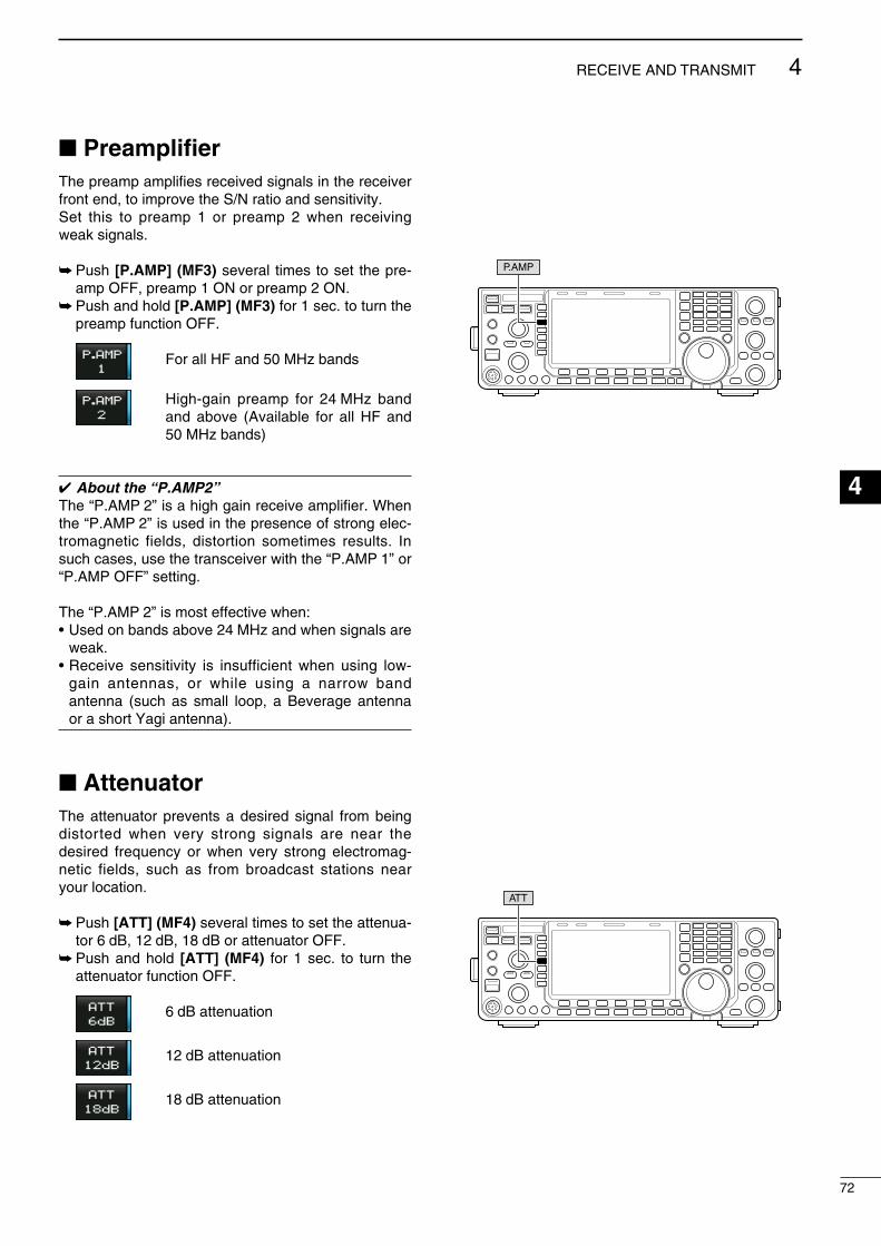
PreamplifierThe preamp amplfes receved sgnals n the recever front end, to mprove the S/N rato and senstvty.Set ths to preamp 1 or preamp 2 when recevng weak sgnals.
Push [P.AMP] (MF3) several tmes to set the pre-amp OFF, preamp 1 ON or preamp 2 ON.
Push and hold [P.AMP] (MF3) for 1 sec. to turn the preamp functon OFF.
For all HF and 50 MHz bands
Hgh-gan preamp for 24 MHz band and above (Avalable for all HF and 50 MHz bands)
About the “P.AMP2”The “P.AMP 2” s a hgh gan receve amplfer. When the “P.AMP 2” s used n the presence of strong elec-tromagnetc felds, dstorton sometmes results. In such cases, use the transcever wth the “P.AMP 1” or “P.AMP OFF” settng.
The “P.AMP 2” s most effectve when:• Used on bands above 24 MHz and when sgnals are
weak.• Receve senstvty s nsuffcent when usng low-
gan antennas, or whle usng a narrow band antenna (such as small loop, a Beverage antenna or a short Yag antenna).
AttenuatorThe attenuator prevents a desred sgnal from beng dstorted when very strong sgnals are near the desred frequency or when very strong electromag-netc felds, such as from broadcast statons near your locaton.
Push [ATT] (MF4) several tmes to set the attenua-tor 6 dB, 12 dB, 18 dB or attenuator OFF.
Push and hold [ATT] (MF4) for 1 sec. to turn the attenuator functon OFF.
6 dB attenuaton
12 dB attenuaton
18 dB attenuaton
P.AMP
ATT
72
4RECEIVE AND TRANSMIT
1
2
3
4
5
6
7
8
9
10
11
12
13
14
15
16
17
18
19
20
21
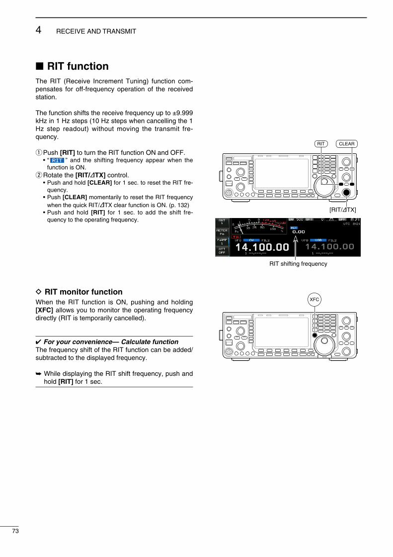
RIT functionThe RIT (Receve Increment Tunng) functon com-pensates for off-frequency operaton of the receved staton.
The functon shfts the receve frequency up to ±9.999 kHz n 1 Hz steps (10 Hz steps when cancellng the 1 Hz step readout) wthout movng the transmt fre-quency.
q Push [RIT] to turn the RIT functon ON and OFF. • “ ” and the shftng frequency appear when the
functon s ON.w Rotate the [RIT/∂TX] control. • Push and hold [CLEAR] for 1 sec. to reset the RIT fre-
quency. • Push [CLEAR] momentarly to reset the RIT frequency
when the quck RIT/∂TX clear functon s ON. (p. 132) • Push and hold [RIT] for 1 sec. to add the shft fre-
quency to the operatng frequency.
D RIT monitor functionWhen the RIT functon s ON, pushng and holdng [XFC] allows you to montor the operatng frequency drectly (RIT s temporarly cancelled).
For your convenience— Calculate functionThe frequency shft of the RIT functon can be added/subtracted to the dsplayed frequency.
Whle dsplayng the RIT shft frequency, push and hold [RIT] for 1 sec.
[RIT/∂TX]
CLEARRIT
XFC
RIT shftng frequency
73
4 RECEIVE AND TRANSMIT
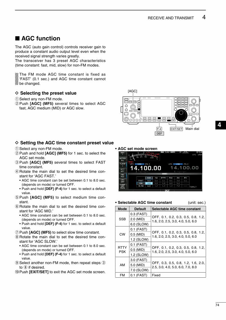
AGC functionThe AGC (auto gan control) controls recever gan to produce a constant audo output level even when the receved sgnal strength vares greatly.The transcever has 3 preset AGC characterstcs (tme constant: fast, md, slow) for non-FM modes.
The FM mode AGC tme constant s fxed as ‘FAST’ (0.1 sec.) and AGC tme constant cannot be changed.
D Selecting the preset valueq Select any non-FM mode.w Push [AGC] (MF5) several tmes to select AGC
fast, AGC medum (MID) or AGC slow.
F-4 EXIT/SET Main dialDEF
[AGC]
D Setting the AGC time constant preset valueq Select any non-FM mode.w Push and hold [AGC] (MF5) for 1 sec. to select the
AGC set mode.e Push [AGC] (MF5) several tmes to select FAST
tme constant.r Rotate the man dal to set the desred tme con-
stant for ‘AGC FAST.’ • AGC tme constant can be set between 0.1 to 8.0 sec.
(depends on mode) or turned OFF. • Push and hold [DEF] (F-4) for 1 sec. to select a default
value.t Push [AGC] (MF5) to select medum tme con-
stant.y Rotate the man dal to set the desred tme con-
stant for ‘AGC MID.’ • AGC tme constant can be set between 0.1 to 8.0 sec.
(depends on mode) or turned OFF. • Push and hold [DEF] (F-4) for 1 sec. to select a default
value.u Push [AGC] (MF5) to select slow tme constant.i Rotate the man dal to set the desred tme con-
stant for ‘AGC SLOW.’ • AGC tme constant can be set between 0.1 to 8.0 sec.
(depends on mode) or turned OFF. • Push and hold [DEF] (F-4) for 1 sec. to select a default
value.o Select another non-FM mode, then repeat steps e
to i f desred.!0 Push [EXIT/SET] to ext the AGC set mode screen.
• AGC set mode screen
• Selectable AGC time constant (unt: sec.)
Mode Default Selectable AGC time constant
SSB
0.3 (FAST)OFF, 0.1, 0.2, 0.3, 0.5, 0.8, 1.2, 1.6, 2.0, 2.5, 3.0, 4.0, 5.0, 6.0
2.0 (MID)
6.0 (SLOW)
CW
0.1 (FAST)OFF, 0.1, 0.2, 0.3, 0.5, 0.8, 1.2, 1.6, 2.0, 2.5, 3.0, 4.0, 5.0, 6.0
0.5 (MID)
1.2 (SLOW)
RTTYPSK
0.1 (FAST)OFF, 0.1, 0.2, 0.3, 0.5, 0.8, 1.2, 1.6, 2.0, 2.5, 3.0, 4.0, 5.0, 6.0
0.5 (MID)
1.2 (SLOW)
AM
3.0 (FAST)OFF, 0.3, 0.5, 0.8, 1.2, 1.6, 2.0, 2.5, 3.0, 4.0, 5.0, 6.0, 7.0, 8.0
5.0 (MID)
7.0 (SLOW)
FM 0.1 (FAST) Fxed
74
4RECEIVE AND TRANSMIT
1
2
3
4
5
6
7
8
9
10
11
12
13
14
15
16
17
18
19
20
21
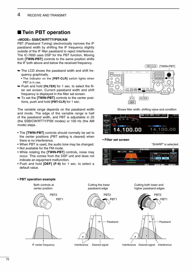
Twin PBT operation<MODE> SSB/CW/RTTY/PSK/AMPBT (Passband Tunng) electroncally narrows the IF passband wdth by shftng the IF frequency slghtly outsde of the IF flter passband to reject nterference. The IC-7600 uses DSP for the PBT functon. Movng both [TWIN-PBT] controls to the same poston shfts the IF both above and below the receved frequency.
The LCD shows the passband wdth and shft fre-quency graphcally.
• The ndcator on the [PBT-CLR] swtch lghts when PBT s n use.
Push and hold [FILTER] for 1 sec. to select the fl-ter set screen. Current passband wdth and shft frequency s dsplayed n the flter set screen.
To set the [TWIN-PBT] controls to the center pos-tons, push and hold [PBT-CLR] for 1 sec.
The varable range depends on the passband wdth and mode. The edge of the varable range s half of the passband wdth, and PBT s adjustable n 25 (the SSB/CW/RTTY/PSK modes) or 100 Hz (the AM mode) steps.
• The [TWIN-PBT] controls should normally be set to the center postons (PBT settng s cleared) when there s no nterference.
• When PBT s used, the audo tone may be changed.• Not avalable for the FM mode.• Whle rotatng the [TWIN-PBT] controls, nose may
occur. Ths comes from the DSP unt and does not ndcate an equpment malfuncton.
• Push and hold [DEF] (F-4) for 1 sec. to select a default value.
• PBT operation example
PBT2
PBT1
PBT2
PBT1
PBT2
PBT1
IF center frequency Interference Desired signal
Passband
Both controls at center position
Cutting the lower passband edge
Cutting both lower and higher passband edges
Interference InterferenceDesired signal
Passband
[TWIN-PBT]PBT-CLR
FILTERF-4
DEF
Shows filter width, shifting value and condition
• Filter set screen“SHARP” is selected.
75
4 RECEIVE AND TRANSMIT
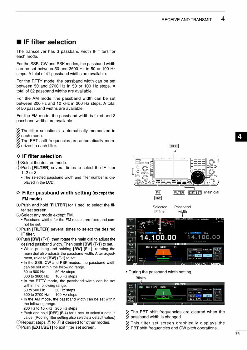
IF filter selectionThe transcever has 3 passband wdth IF flters for each mode.
For the SSB, CW and PSK modes, the passband wdth can be set between 50 and 3600 Hz n 50 or 100 Hz steps. A total of 41 passband wdths are avalable.
For the RTTY mode, the passband wdth can be set between 50 and 2700 Hz n 50 or 100 Hz steps. A total of 32 passband wdths are avalable.
For the AM mode, the passband wdth can be set between 200 Hz and 10 kHz n 200 Hz steps. A total of 50 passband wdths are avalable.
For the FM mode, the passband wdth s fxed and 3 passband wdths are avalable.
The flter selecton s automatcally memorzed n each mode.The PBT shft frequences are automatcally mem-orzed n each flter.
D IF filter selectionq Select the desred mode.w Push [FILTER] several tmes to select the IF flter
1, 2 or 3. • The selected passband wdth and flter number s ds-
played n the LCD.
D Filter passband width setting (except the FM mode)
q Push and hold [FILTER] for 1 sec. to select the fl-ter set screen.
w Select any mode except FM. • Passband wdths for the FM modes are fxed and can-
not be set.e Push [FILTER] several tmes to select the desred
IF flter.r Push [BW] (F-1), then rotate the man dal to adjust the
desred passband wdth. Then push [BW] (F-1) to set. • Whle pushng and holdng [BW] (F-1), rotatng the
man dal also adjusts the passband wdth. After adjust-ment, release [BW] (F-1) to set.
• In the SSB, CW and PSK modes, the passband wdth can be set wthn the followng range.
50 to 500 Hz 50 Hz steps 600 to 3600 Hz 100 Hz steps • In the RTTY mode, the passband wdth can be set
wthn the followng range. 50 to 500 Hz 50 Hz steps 600 to 2700 Hz 100 Hz steps • In the AM mode, the passband wdth can be set wthn
the followng range. 200 Hz to 10 kHz 200 Hz steps • Push and hold [DEF] (F-4) for 1 sec. to select a default
value. (Roofng flter settng also selects a default value.)t Repeat steps w to r f desred for other modes.y Push [EXIT/SET] to ext flter set screen.
FILTERF-1
BW
F-4
DEF
EXIT/SET Main dial
SelectedIF filter
Passbandwidth
• Durng the passband wdth settng
The PBT shft frequences are cleared when the passband wdth s changed.
Ths flter set screen graphcally dsplays the PBT shft frequences and CW ptch operatons.
76
4RECEIVE AND TRANSMIT
1
2
3
4
5
6
7
8
9
10
11
12
13
14
15
16
17
18
19
20
21
Blnks

D Roofing filter selectionThe IC-7600 has 3, 6 and 15 kHz roofng flters at the 1st IF frequency. The roofng flter provdes nterfer-ence reducton from nearby strong sgnals.
q Push and hold [FILTER] for 1 sec. to select the fl-ter set screen.
w Select any mode except FM.e Push [ROOFING] (F-5] to select the desred flter
wdth from 15 kHz, 6 kHz and 3 kHz. • Push and hold [DEF] (F-4) for 1 sec. to select a default
value. (Flter passband wdth settng also selects a default value.)
r Push [EXIT/SET] to ext flter set screen.
D DSP filter shapeThe type of DSP flter shape for each SSB, SSB data and CW can be selected ndependently from soft and sharp.
q Push and hold [FILTER] for 1 sec. to select the fl-ter set screen.
w Select the SSB, SSB data or CW mode.e Push [SHAPE] (F-6) several tmes to select the
desred flter shape from soft and sharp.r Push [EXIT/SET] to ext flter set screen.
The flter shape can be set for each band (HF and 50 MHz bands), mode, as well as the passband wdth settng (CW only) ndependently from your default settng n the flter shape set mode.
F-5F-4
DEF ROOFING
EXIT/SETFILTER
• Filter set screen“SHARP” is selected.
• Default roofing filter (unt: kHz)
Mode FIL1 FIL2 FIL3 Mode FIL1 FIL2 FIL3
SSB 15 15 6 RTTY 15 6 6
SSB-D 6 6 6 PSK 6 6 6
CW 6 6 6 AM 15 15 15
F-1 F-2
F-6F-4
DEF SHAPE
EXIT/SET Main dialFILTER
77
4 RECEIVE AND TRANSMIT
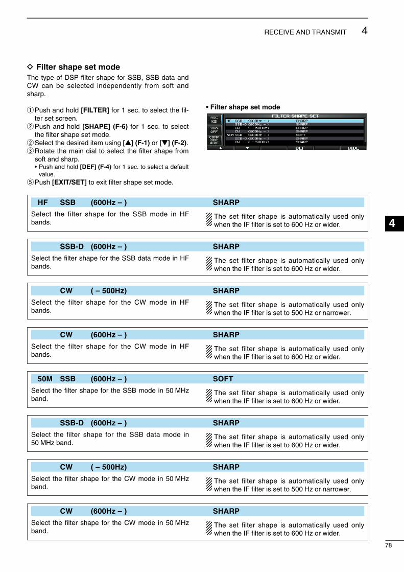
HF SSB (600Hz – ) SHARP
Select the flter shape for the SSB mode n HF bands.
The set filter shape s automatcally used only when the IF filter s set to 600 Hz or wder.
SSB-D (600Hz – ) SHARP
Select the flter shape for the SSB data mode n HF bands.
The set filter shape s automatcally used only when the IF filter s set to 600 Hz or wder.
CW ( – 500Hz) SHARP
Select the flter shape for the CW mode n HF bands.
The set filter shape s automatcally used only when the IF filter s set to 500 Hz or narrower.
CW (600Hz – ) SHARP
Select the flter shape for the CW mode n HF bands.
The set filter shape s automatcally used only when the IF filter s set to 600 Hz or wder.
50M SSB (600Hz – ) SOFT
Select the flter shape for the SSB mode n 50 MHz band.
The set filter shape s automatcally used only when the IF filter s set to 600 Hz or wder.
SSB-D (600Hz – ) SHARP
Select the flter shape for the SSB data mode n 50 MHz band.
The set filter shape s automatcally used only when the IF filter s set to 600 Hz or wder.
CW ( – 500Hz) SHARP
Select the flter shape for the CW mode n 50 MHz band.
The set filter shape s automatcally used only when the IF filter s set to 500 Hz or narrower.
CW (600Hz – ) SHARP
Select the flter shape for the CW mode n 50 MHz band.
The set filter shape s automatcally used only when the IF filter s set to 600 Hz or wder.
78
4RECEIVE AND TRANSMIT
1
2
3
4
5
6
7
8
9
10
11
12
13
14
15
16
17
18
19
20
21
D Filter shape set modeThe type of DSP flter shape for SSB, SSB data and CW can be selected ndependently from soft and sharp.
q Push and hold [FILTER] for 1 sec. to select the fl-ter set screen.
w Push and hold [SHAPE] (F-6) for 1 sec. to select the flter shape set mode.
w Select the desred tem usng [Y] (F-1) or [Z] (F-2).e Rotate the man dal to select the flter shape from
soft and sharp. • Push and hold [DEF] (F-4) for 1 sec. to select a default
value.t Push [EXIT/SET] to ext flter shape set mode.
• Filter shape set mode
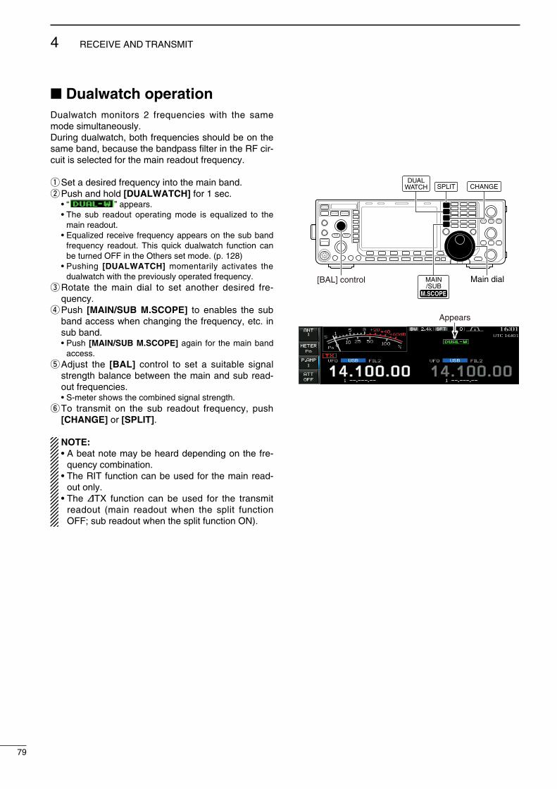
Dualwatch operationDualwatch montors 2 frequences wth the same mode smultaneously.Durng dualwatch, both frequences should be on the same band, because the bandpass flter n the RF cr-cut s selected for the man readout frequency.
q Set a desred frequency nto the man band.w Push and hold [DUALWATCH] for 1 sec. • “ ” appears. • The sub readout operatng mode s equalzed to the
man readout. • Equalzed receve frequency appears on the sub band
frequency readout. Ths quck dualwatch functon can be turned OFF n the Others set mode. (p. 128)
• Pushng [DUALWATCH] momentarly actvates the dualwatch wth the prevously operated frequency.
e Rotate the man dal to set another desred fre-quency.
r Push [MAIN/SUB M.SCOPE] to enables the sub band access when changng the frequency, etc. n sub band.
• Push [MAIN/SUB M.SCOPE] agan for the man band access.
t Adjust the [BAL] control to set a sutable sgnal strength balance between the man and sub read-out frequences.
• S-meter shows the combned sgnal strength.y To transmt on the sub readout frequency, push
[CHANGE] or [SPLIT].
NOTE:• A beat note may be heard dependng on the fre-
quency combnaton.• The RIT functon can be used for the man read-
out only.• The ∂TX functon can be used for the transmt
readout (man readout when the splt functon OFF; sub readout when the splt functon ON).
[BAL] control
DUALWATCH SPLIT CHANGE
MAIN/SUB
M.SCOPEM.SCOPE
Main dial
Appears
79
4 RECEIVE AND TRANSMIT

• Scanning during dualwatchScannng operates only for the man readout. To operate the scan durng dualwatch, scan on the man readout and use the sub readout for your QSO usng both dualwatch and splt frequency operaton.
q Program the desred programmed scan edges n the same amateur band. See p. 101 for program-mng.
• If you plan to operate a ∂F scan, programmng the scan edges may not be necessary.
w Push [SPLIT] to turn the splt frequency functon ON.
• “ ” appears.e Select VFO mode for the man readout.r Set the desred operatng frequency for the man
readout.t Push and hold [DUALWATCH] for 1 sec. • “ ” appears. • Equalzed receve frequency and operatng mode
appear on the sub band readout and the dualwatch functon s turned ON.
y Push [SCAN] (F-5) to select the scan screen. • Push [EXIT/SET] several tmes to close any mult-func-
ton screens, f necessary.u Push [PROG] (F-1) or [∂F] (F-2) to start the pro-
grammed scan or ∂F scan, respectvely. • Scan actvates on the man readout between the pro-
grammed scan edges or wthn the ∂F span. • Transmttng on the sub readout stops the scan.i To cancel the scan, push [EXIT/SET].
F-1 F-2 F-5 EXIT/SET
DUALWATCH SPLIT
PROG SCAN∂F
80
4RECEIVE AND TRANSMIT
1
2
3
4
5
6
7
8
9
10
11
12
13
14
15
16
17
18
19
20
21
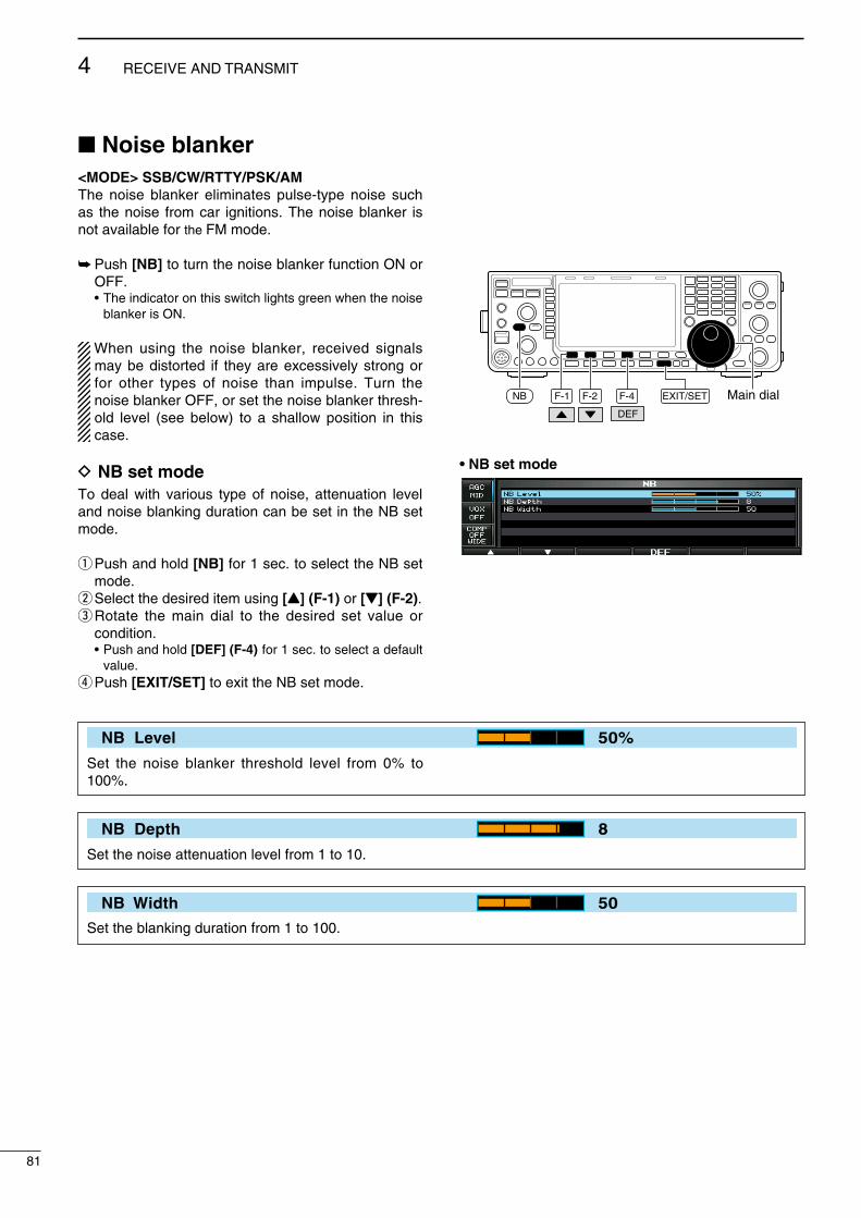
Noise blanker<MODE> SSB/CW/RTTY/PSK/AMThe nose blanker elmnates pulse-type nose such as the nose from car gntons. The nose blanker s not avalable for the FM mode.
Push [NB] to turn the nose blanker functon ON or OFF.
• The ndcator on ths swtch lghts green when the nose blanker s ON.
When usng the nose blanker, receved sgnals may be dstorted f they are excessvely strong or for other types of nose than mpulse. Turn the nose blanker OFF, or set the nose blanker thresh-old level (see below) to a shallow poston n ths case.
D NB set modeTo deal wth varous type of nose, attenuaton level and nose blankng duraton can be set n the NB set mode.
q Push and hold [NB] for 1 sec. to select the NB set mode.
w Select the desred tem usng [Y] (F-1) or [Z] (F-2).e Rotate the man dal to the desred set value or
condton. • Push and hold [DEF] (F-4) for 1 sec. to select a default
value.r Push [EXIT/SET] to ext the NB set mode.
F-1 F-2 F-4
DEF
EXIT/SET Main dialNB
• NB set mode
NB Level 50%
Set the nose blanker threshold level from 0% to 100%.
NB Depth 8
Set the nose attenuaton level from 1 to 10.
NB Width 50
Set the blankng duraton from 1 to 100.
81
4 RECEIVE AND TRANSMIT

Noise reductionThe nose reducton functon reduces random nose components and enhances desred sgnals whch are bured n nose. The DSP performs the random nose reducton functon.
q Push [NR] to turn the nose reducton ON. • The ndcator on ths swtch lghts green.w Rotate the [NR] control to adjust the nose reduc-
ton level.e Push [NR] to turn the nose reducton OFF. • The ndcator goes off.
Large rotatons of the [NR] control results n audo sgnal maskng or dstorton. Set the [NR] control for maxmum readablty.
Dial lock function The dal lock functon prevents frequency changes by accdental movement of the tunng dal. The lock functon electroncally locks the dal.
Push and hold [SPEECH/LOCK] for 1 sec. to turn the dal lock functon ON or OFF.
• The [LOCK] ndcator lghts when the dal lock functon s n use.
• Whle splt frequency operaton s ON, the splt lock functon may be turned ON. (p. 89)
NOTE: When “LOCK/SPEECH” s selected n [[SPEECH/LOCK] Swtch] tem n the Others set mode, pushng [SPEECH/LOCK] actvates the dal lock functon. (p. 131)
[NR]control
NR
Noise reduction OFF Noise reduction activated
Desired signal (CW)
Noise components
[LOCK] indicator
SPEECHLOCK
82
4RECEIVE AND TRANSMIT
1
2
3
4
5
6
7
8
9
10
11
12
13
14
15
16
17
18
19
20
21

Notch functionThs transcever has auto and manual notch func-tons.The auto notch functon uses DSP to automatcally attenuate beat tones, tunng sgnals, etc., even f they are movng. The manual notch can be set to attenu-ate a frequency va the [NOTCH] control.The auto notch can be used n the SSB, AM and FM mode.The manual notch can be used n the SSB, CW, RTTY, PSK and AM modes.
Push [NOTCH] to toggle the notch functon between auto, manual and OFF n the SSB and AM modes.
• Ether auto or manual notch functon can be deact-vated n the Others set mode. (p. 132)
Push [NOTCH] to turn the manual notch functon ON or OFF n the CW, RTTY, PSK modes.
Push [NOTCH] to turn the auto notch functon ON or OFF n the FM mode.
• The ndcator on ths swtch lghts green when the auto or manual notch functon s ON.
• When the manual notch functon s ON, push and hold [NOTCH] for 1 sec. to select the notch flter wdth for manual notch from wde, mddle and narrow.
• Set to attenuate a frequency for manual notch va the [NOTCH] control.
• “ ” appears when auto notch s n use. • “ ” appears when manual notch s n use.
Whle tunng the manual notch, nose may be heard. Ths comes from the DSP unt and does not ndcate an equpment malfuncton.
Auto tune function<MODE> CW/AMThe automatc tunng functon tunes the dsplayed fre-quency automatcally when an off-frequency sgnal s receved wthn the range ±500 Hz (CW) or ±5 kHz (AM). Ths functon s actve whle n CW or AM s selected.
Push [AUTO TUNE] to toggle the auto tune func-ton ON or OFF.
• “ ” blnks when auto tune functon s act-vated.
• After 2 sec. has passed, the auto tune functon stops tunng automatcally even t’s stll off-frequency.
IMPORTANT!When recevng a weak sgnal, or recevng a sg-nal wth nterference, the automatc tunng functon may tune the recever to an undesred sgnal.
NOTE: The automatc tunng functon does not actve on the sub band.
[NOTCH]control
NOTCH
• Auto notch indicationAppears
• Manual notch indicationAppears
Unwanted tone frequency
Desired signal (AF)
Desired signal (AF)
Particular frequency is attenuated
Auto notch OFF Auto notch ON
AUTOTUNE
Appears
83
4 RECEIVE AND TRANSMIT
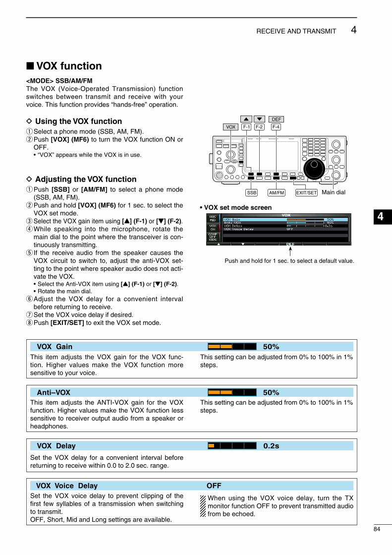
VOX function<MODE> SSB/AM/FMThe VOX (Voce-Operated Transmsson) functon swtches between transmt and receve wth your voce. Ths functon provdes “hands-free” operaton.
D Using the VOX functionq Select a phone mode (SSB, AM, FM).w Push [VOX] (MF6) to turn the VOX functon ON or
OFF. • “VOX” appears whle the VOX s n use.
D Adjusting the VOX functionq Push [SSB] or [AM/FM] to select a phone mode
(SSB, AM, FM).w Push and hold [VOX] (MF6) for 1 sec. to select the
VOX set mode.e Select the VOX gan tem usng [Y] (F-1) or [Z] (F-2).r Whle speakng nto the mcrophone, rotate the
man dal to the pont where the transcever s con-tnuously transmttng.
t If the receve audo from the speaker causes the VOX crcut to swtch to, adjust the ant-VOX set-tng to the pont where speaker audo does not act-vate the VOX.
• Select the Ant-VOX tem usng [Y] (F-1) or [Z] (F-2). • Rotate the man dal.y Adjust the VOX delay for a convenent nterval
before returnng to receve.u Set the VOX voce delay f desred.i Push [EXIT/SET] to ext the VOX set mode.
F-1 F-2 F-4
DEF
EXIT/SET Main dial
VOX
SSB AM/FM
• VOX set mode screen
VOX Gain 50%Ths tem adjusts the VOX gan for the VOX func-ton. Hgher values make the VOX functon more senstve to your voce.
Ths settng can be adjusted from 0% to 100% n 1%steps.
Anti–VOX 50%Ths tem adjusts the ANTI-VOX gan for the VOX functon. Hgher values make the VOX functon less senstve to recever output audo from a speaker or headphones.
Ths settng can be adjusted from 0% to 100% n 1%steps.
VOX Delay 0.2s
Set the VOX delay for a convenent nterval before returnng to receve wthn 0.0 to 2.0 sec. range.
VOX Voice Delay OFFSet the VOX voce delay to prevent clppng of the frst few syllables of a transmsson when swtchng to transmt.OFF, Short, Md and Long settngs are avalable.
When usng the VOX voce delay, turn the TX montor functon OFF to prevent transmtted audo from be echoed.
84
4RECEIVE AND TRANSMIT
1
2
3
4
5
6
7
8
9
10
11
12
13
14
15
16
17
18
19
20
21
Push and hold for 1 sec. to select a default value.
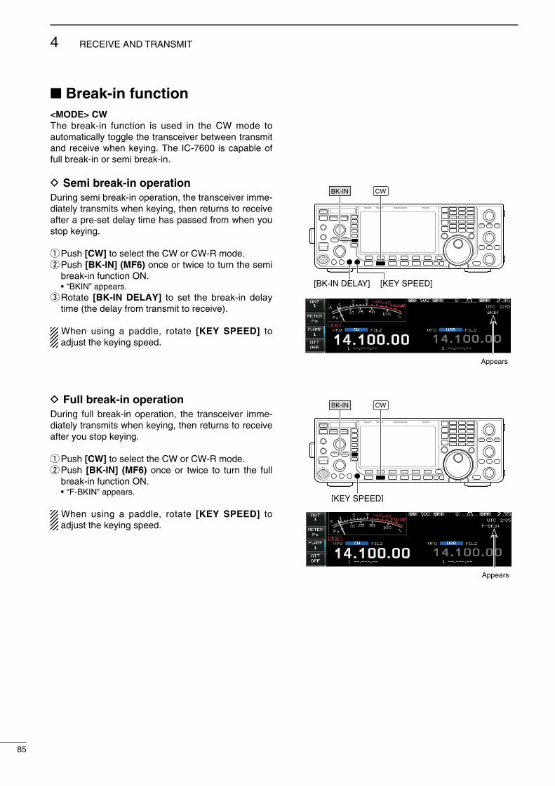
Break-in function<MODE> CWThe break-n functon s used n the CW mode to automatcally toggle the transcever between transmt and receve when keyng. The IC-7600 s capable of full break-n or sem break-n.
D Semi break-in operationDurng sem break-n operaton, the transcever mme-dately transmts when keyng, then returns to receve after a pre-set delay tme has passed from when you stop keyng.
q Push [CW] to select the CW or CW-R mode.w Push [BK-IN] (MF6) once or twce to turn the sem
break-n functon ON. • “BKIN” appears.e Rotate [BK-IN DELAY] to set the break-n delay
tme (the delay from transmt to receve).
When usng a paddle, rotate [KEY SPEED] to adjust the keyng speed.
D Full break-in operationDurng full break-n operaton, the transcever mme-dately transmts when keyng, then returns to receve after you stop keyng.
q Push [CW] to select the CW or CW-R mode.w Push [BK-IN] (MF6) once or twce to turn the full
break-n functon ON. • “F-BKIN” appears.
When usng a paddle, rotate [KEY SPEED] to adjust the keyng speed.
[BK-IN DELAY] [KEY SPEED]
CWBK-IN
[KEY SPEED]
BK-IN CW
Appears
Appears
85
4 RECEIVE AND TRANSMIT
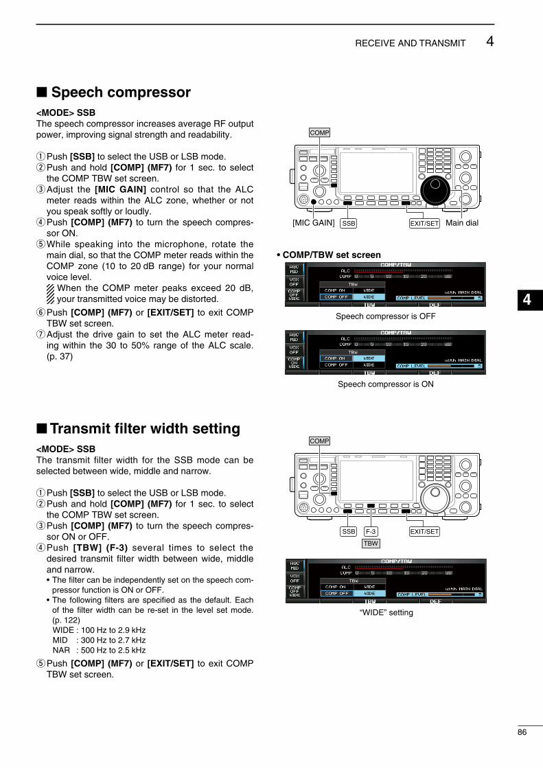
Speech compressor<MODE> SSBThe speech compressor ncreases average RF output power, mprovng sgnal strength and readablty.
q Push [SSB] to select the USB or LSB mode.w Push and hold [COMP] (MF7) for 1 sec. to select
the COMP TBW set screen.e Adjust the [MIC GAIN] control so that the ALC
meter reads wthn the ALC zone, whether or not you speak softly or loudly.
r Push [COMP] (MF7) to turn the speech compres-sor ON.
t Whle speakng nto the mcrophone, rotate the man dal, so that the COMP meter reads wthn the COMP zone (10 to 20 dB range) for your normal voce level.
When the COMP meter peaks exceed 20 dB, your transmtted voce may be dstorted.
y Push [COMP] (MF7) or [EXIT/SET] to ext COMP TBW set screen.
u Adjust the drve gan to set the ALC meter read-ng wthn the 30 to 50% range of the ALC scale. (p. 37)
Transmit filter width setting<MODE> SSBThe transmt flter wdth for the SSB mode can be selected between wde, mddle and narrow.
q Push [SSB] to select the USB or LSB mode.w Push and hold [COMP] (MF7) for 1 sec. to select
the COMP TBW set screen.e Push [COMP] (MF7) to turn the speech compres-
sor ON or OFF.r Push [TBW] (F-3) several tmes to select the
desred transmt flter wdth between wde, mddle and narrow.
• The flter can be ndependently set on the speech com-pressor functon s ON or OFF.
• The followng flters are specfed as the default. Each of the flter wdth can be re-set n the level set mode. (p. 122)
WIDE : 100 Hz to 2.9 kHz MID : 300 Hz to 2.7 kHz NAR : 500 Hz to 2.5 kHz
t Push [COMP] (MF7) or [EXIT/SET] to ext COMP TBW set screen.
[MIC GAIN] EXIT/SET Main dial
COMP
SSB
• COMP/TBW set screen
EXIT/SETF-3
TBW
COMP
SSB
Speech compressor s ON
Speech compressor s OFF
“WIDE” settng
86
4RECEIVE AND TRANSMIT
1
2
3
4
5
6
7
8
9
10
11
12
13
14
15
16
17
18
19
20
21
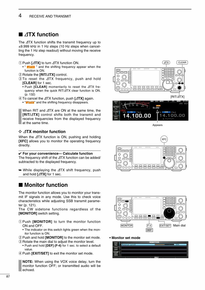
∂TX functionThe ∂TX functon shfts the transmt frequency up to ±9.999 kHz n 1 Hz steps (10 Hz steps when cancel-lng the 1 Hz step readout) wthout movng the receve frequency.
q Push [∂TX] to turn ∂TX functon ON. • “ ” and the shftng frequency appear when the
functon s ON.w Rotate the [RIT/∂TX] control.e To reset the ∂TX frequency, push and hold
[CLEAR] for 1 sec. • Push [CLEAR] momentarly to reset the ∂TX fre-
quency when the quck RIT/∂TX clear functon s ON. (p. 132)
r To cancel the ∂TX functon, push [∂TX] agan. • “ ” and the shftng frequency dsappears.
When RIT and ∂TX are ON at the same tme, the [RIT/∂TX] control shfts both the transmt and receve frequences from the dsplayed frequency at the same tme.
D ∂TX monitor functionWhen the ∂TX functon s ON, pushng and holdng [XFC] allows you to montor the operatng frequency drectly.
For your convenience— Calculate functionThe frequency shft of the ∂TX functon can be added/subtracted to the dsplayed frequency.
Whle dsplayng the ∂TX shft frequency, push and hold [∂TX] for 1 sec.
Monitor functionThe montor functon allows you to montor your trans-mt IF sgnals n any mode. Use ths to check voce characterstcs whle adjustng SSB transmt parame-ter (p. 121).The CW sdetone functons regardless of the [MONITOR] swtch settng.
q Push [MONITOR] to turn the montor functon ON and OFF.
• The ndcator on ths swtch lghts green when the mon-tor functon s ON.
w Push and hold [MONITOR] to the montor set mode.e Rotate the man dal to adjust the montor level. • Push and hold [DEF] (F-4) for 1 sec. to select a default
value.r Push [EXIT/SET] to ext the montor set mode.
NOTE: When usng the VOX voce delay, turn the montor functon OFF; or transmtted audo wll be echoed.
[RIT/∂TX]
∂TX CLEAR
XFC
EXIT/SET Main dialF-4
DEF
MONITOR
• Monitor set mode
Appears
87
4 RECEIVE AND TRANSMIT

Split frequency operationSplt frequency operaton allows you to transmt and receve n the same mode on two dfferent frequen-ces. Splt frequency operaton s performed usng 2 frequences on the man and sub readouts.
The followng s an example of settng 21.290 MHz for recevng and 21.310 MHz for transmttng.
q Set 21.290 MHz (USB) n VFO mode.w Push [SPLIT], then push and hold [CHANGE] for 1
sec. • The quck splt functon s much more convenent for
selectng the transmt frequency. See the next secton for detals.
• The equalzed transmt frequency and “ ” appear on the LCD.
• [SPLIT] ndcator lghts. • “ ” appears to show the transmt frequency read-
out.e Whle pushng and holdng [XFC], rotate the man
dal to set the transmt frequency to 21.310 MHz. • The transmt frequency can be montored whle push-
ng [XFC].r Now you can receve on 21.290 MHz and transmt
on 21.310 MHz.
To change the transmt and receve frequences, push [CHANGE] to exchange the man and sub readouts.
CONVENIENT• Direct shift frequency inputThe shft frequency can be entered drectly.q Push [F-INP ENT].w Enter the desred shft frequency wth the dgt keys. • 1 kHz to 9.999 MHz can be set. • When you requre a negatve shft drecton, push
[GENE •] n advance.e Push [SPLIT] to nput the shft frequency n the sub
readout and the splt functon s turned ON.
• Dualwatch functionThe dualwatch functon s convenent for tunng the transmt frequency whle montorng both frequences used for transmttng and recevng.
• Split lock function (p. 129)Accdentally releasng [XFC] whle rotatng the man dal changes the receve frequency. To prevent ths, use both the splt lock and dal lock functons to change the transmt frequency only. The splt lock functon cancels the dal lock functon whle pushng [XFC] durng splt frequency operaton.
The splt lock functon s OFF by default, but can be turned ON n the Others set mode.
Main dial
[SPLIT] indicator SPLIT
MAIN/SUB
M.SCOPEM.SCOPE
XFCCHANGE
• When the split function ON
• When [XFC] is pushed
• The split frequency operation is ready
88
4RECEIVE AND TRANSMIT
1
2
3
4
5
6
7
8
9
10
11
12
13
14
15
16
17
18
19
20
21
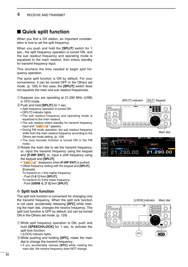
Quick split functionWhen you fnd a DX staton, an mportant consder-aton s how to set the splt frequency.
When you push and hold the [SPLIT] swtch for 1 sec., the splt frequency operaton s turned ON, and the sub readout frequency and operatng mode s equalzed to the man readout, then enters standby for transmt frequency nput.
Ths shortens the tme needed to begn splt fre-quency operaton.
The quck splt functon s ON by default. For your convenence, t can be turned OFF n the Others set mode. (p. 129) In ths case, the [SPLIT] swtch does not equalze the man and sub readout frequences.
q Suppose you are operatng at 21.290 MHz (USB) n VFO mode.
w Push and hold [SPLIT] for 1 sec. • Splt frequency operaton s turned ON. • [SPLIT] ndcator lghts. • The sub readout frequency and operatng mode s
equalzed to the man readout. • The sub readout enters standby for transmt frequency
nput and “ ” appears. • Durng FM mode operaton, the sub readout frequency
shfts from the man readout frequency accordng to the Others set mode settng. (p. 129)
• The tone encoder functon s turned ON n the FM mode.
e Rotate the man dal to set the transmt frequency; or, nput the transmt frequency usng the keypad and [F-INP ENT]; or, nput a shft frequency usng the keypad and [SPLIT].
• “ ” dsappears when [F-INP ENT] s pushed. • Offset frequency settng wth the keypad and [SPLIT]. [Example] To transmt on 1 kHz hgher frequency: - Push [1.8 1] then [SPLIT]. To transmt on 3 kHz lower frequency: - Push [GENE •], [7 3] then [SPLIT].
D Split lock functionThe splt lock functon s convenent for changng only the transmt frequency. When the splt lock functon s not used, accdentally releasng [XFC] whle rotat-ng the man dal, changes the receve frequency. The splt lock functon s OFF by default, but can be turned ON n the Others set mode. (p. 129)
q Whle splt frequency operaton s ON, push and hold [SPEECH/LOCK] for 1 sec. to actvate the splt lock functon.
• [LOCK] ndcator lghts.w Whle pushng and holdng [XFC], rotate the man
dal to change the transmt frequency. • If you accdentally release [XFC] whle rotatng the
man dal, the receve frequency does NOT change.
Main dial
[SPLIT] indicator KeypadSPLIT
Main dial[LOCK] indicator
SPEECHLOCKXFC
89
4 RECEIVE AND TRANSMIT

About digital voice recorderThe IC-7600 has dgtal voce memores, up to 4 messages for transmt, and up to 20 messages for receve.A maxmum message length of 30 sec. can be recorded nto receve memory (total message length for all channels of up to 209 sec.) and a total mes-sage length of up to 99 sec. can be recorded n trans-mt memory.The transmt memory s very convenent for repeated CQ and exchange transmssons n contests, as well as when makng repeated calls to DX’pedtons.
q Select any mode.w Push [VOICE] (F-2) to dsplay voce recorder
screen.e Push [EXIT/SET] to dsplay voce recorder menu.r Push [PLAY] (F-1) or [MIC REC] (F-2) to select
the desred memory channel screen, then record audo or playback the contents.
t Push [EXIT/SET] twce to ext voce recorder screen.
F-2
F-1 EXIT/SET PLAYREC
PLAY
VOICE MIC REC/
• Example— When [REC] is pushed and held for 1sec.
• Example— When [REC] is pushed momentarily
• Playing back the all contents in a channel • Playing back the end of 5 sec.* in a channel
20 sec.
15 sec.(default)
30 sec. (max.) Not playing back Play back (5 sec.; default)
3 sec.
30 sec.Push REC momentarily within 30 sec. after pushing and holding REC for 1 sec., records the all contents.
Push REC momentarily records the contents of the previous 15 sec.*
When REC is pushed momentarily again within 15 sec.* from the last REC operation, all the contents between REC operations will be recorded.
Push REC momentarily after passing 30 sec. from pushing and holding REC for 1 sec., records the 30 sec. before canceling the record.
These contents won’t be recorded.
*The playing back time period can be changed with “Short Play Time” in voice set mode (p. 97).
NOTE: The contents will be recorded into an independent memory channels automatically.
Push and hold REC for 1 sec.(starts recording)
Push REC momentarily Push REC momentarily
Push REC momentarily(stops recording)
Push and hold REC for 1 sec.(starts recording)
Push REC momentarily(stops recording)
Push [PLAY] (F-3) momentarily.Or, push and hold PLAY for 1 sec. Push PLAY momentarily.
*The recording time period can be changed with “Normal Rec Time” in voice set mode (p. 97).
About recording received audio and playing back the contents
5
90
VOICE RECORDER FUNCTIONS
1
2
3
4
5
6
7
8
9
10
11
12
13
14
15
16
17
18
19
20
21

Recording a received audioUp to 20 receve voce memores can be recorded n the IC-7600. A total of 209 sec. of audo can be recorded n receve messages. However, the max-mum recordable length of a sngle message s 30 sec.
Ths voce recorder records not only the receved audo, but also the nformaton such as operatng fre-quency, mode, and the recordng tme for your future reference.
D Basic recordingq Push [EXIT/SET] several tmes to close any mult-
functon screens, f necessary.w Select the desred mode.e Push [VOICE] (F-2) to call up the voce recorder
screen. • Prevously selected screen, TX or RX memory, s ds-
played. If the TX memory channel (T1–T4) appears, push [T/R] (F-6) to select an RX memory channel.
r Push and hold [REC] for 1 sec. to start recordng. • The operatng frequency, mode and current tme are
automatcally programmed as the memory names.t Push [REC] momentarly to stop recordng.
IMPORTANT!Push [REC] to stop recordng before, or when 30 sec. has elapsed from the start of recordng.The voce recorder memory records 30 sec. (max.) of audo before [REC] s pushed.For example, when recordng 40 sec. of audo, the frst 10 sec. audo wll be overwrtten wth the last 10 sec., so that the total of audo recorded s only 30 sec.When you record the 21st audo message, or when the total audo length exceeds 209 sec., the oldest recorded audo s automatcally erased to make room for the new audo.
y Push [EXIT/SET] twce to ext the voce recorder screen.
NOTE: When transmt (or [PTT] s pushed) whle recordng, no audo wll be recorded.
D One-touch recordingTo record the receved sgnal mmedately, one-touch voce recordng s avalable.
Push [REC] momentarly to store the prevous 15 sec. audo.
• The recordable tme perod can be set n the voce set mode. (p. 97)
F-2 F-6 EXIT/SET
VOICE T/R
REC
The remaining time for recordingis displayed.
REC
91
5 VOICE RECORDER FUNCTIONS

Playing the recorded audioD Basic playingq Push [EXIT/SET] several tmes to close any mult-
functon screens, f necessary.w Push [VOICE] (F-2) to call up the voce recorder
screen. • Prevously selected screen, TX or RX memory, s ds-
played. If the TX memory message (T1–T4) appears, push [T/R] (F-6) to select RX memory message.
e Push [Y] (F-1) or [Z] (F-2) to select the desred voce memory to playback.
r Push [PLAY] (F-3) to start playback. • “ ” ndcators appear and the tmer counts
down.t Push [PLAY] (F-3) agan to stop playback f
desred. • Playback s termnated automatcally when all of the
recorded contents n the message are played.y Push [EXIT/SET] twce to ext the voce recorder
screen.
D One-touch playingThe prevously recorded audo n message 1 can be played back wthout selectng voce recorder screen.
Push [PLAY] momentarly to playback the last 5 sec. of the prevously recorded audo.
• To playback all contents of the prevously recorded audo, push and hold [PLAY] for 1 sec.
• “ ” ndcator appears. • Playback s termnated automatcally when all of the
recorded contents n the message are played, or after 5 sec.
• The playback tme perod can be set n the voce set mode. (p. 97)
F-2
F-3
F-1
PLAY
EXIT/SET
T/R
F-6
VOICE /
Appears
Appears
Counts down
PLAY
92
5VOICE RECORDER FUNCTIONS
1
2
3
4
5
6
7
8
9
10
11
12
13
14
15
16
17
18
19
20
21
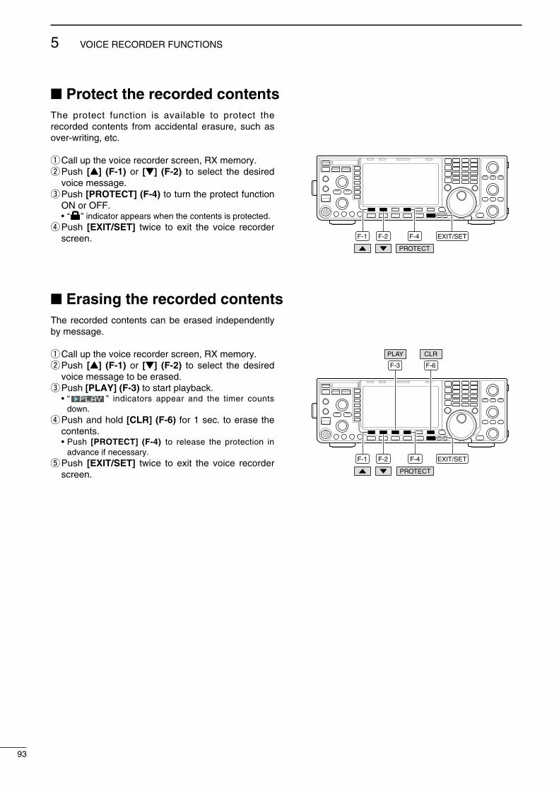
Protect the recorded contentsThe protect functon s avalable to protect the recorded contents from accdental erasure, such as over-wrtng, etc.
q Call up the voce recorder screen, RX memory.w Push [Y] (F-1) or [Z] (F-2) to select the desred
voce message.e Push [PROTECT] (F-4) to turn the protect functon
ON or OFF. • “ ” ndcator appears when the contents s protected.r Push [EXIT/SET] twce to ext the voce recorder
screen. F-2 F-4F-1
PROTECT
EXIT/SET
Erasing the recorded contentsThe recorded contents can be erased ndependently by message.
q Call up the voce recorder screen, RX memory.w Push [Y] (F-1) or [Z] (F-2) to select the desred
voce message to be erased.e Push [PLAY] (F-3) to start playback. • “ ” ndcators appear and the tmer counts
down.r Push and hold [CLR] (F-6) for 1 sec. to erase the
contents. • Push [PROTECT] (F-4) to release the protecton n
advance f necessary.t Push [EXIT/SET] twce to ext the voce recorder
screen.
F-2
F-3 F-6
F-1
PLAY CLR
F-4
PROTECT
EXIT/SET
93
5 VOICE RECORDER FUNCTIONS

Recording a message for transmitTo transmt a message usng the voce recorder, record the desred message n advance as descrbed below.The IC-7600 has dgtal voce memores for transms-son, up to 4 messages and a total message length of up to 99 sec. can be recorded.
D Recordingq Push [EXIT/SET] several tmes to close any mult-
functon screens, f necessary.w Push [VOICE] (F-2) to call up the voce recorder
screen.e Push [EXIT/SET] to select voce recorder menu.r Push [MIC REC] (F-2) to select the voce mc.
record screen.t Push [Y] (F-1) or [Z] (F-2) to select the desred
message.y Whle speakng nto the mcrophone wth your nor-
mal voce level, adjust the [MIC GAIN] control so that the [MIC-REC LEVEL] ndcator reads wthn 100%.
u Push and hold [REC] (F-4) for 1 sec. to start recordng.
• “ ” ndcator appears. • Speak nto the mcrophone wthout pushng [PTT]. • Prevously recorded contents are cleared. • Audo output from the nternal speaker s automatcally
muted.i Push [REC] (F-4) momentarly to stop recordng. • The recordng s termnated automatcally when the
remanng tme becomes 0 sec.o Push [EXIT/SET] twce to ext the voce recorder
screen.
D Confirming a message for transmitq Perform the steps q to r as “D Recordng”
above.w Push [Y] (F-1) or [Z] (F-2) to select the desred
message.e Push [PLAY] (F-3) to playback the recorded con-
tents. • “ ” ndcator appears. • Push and hold [CLR] (F-6) for 1 sec. to erase the con-
tents.r Push [PLAY] (F-3) agan to stop playback. • Playback s termnated automatcally when all of the
recorded contents n the message are played.t Push [EXIT/SET] twce to ext the voce recorder
screen.
F-2
F-4
F-1
REC
EXIT/SET
VOICE
MIC REC
Appears Adjust [MIC GAIN] control so that this indicator reads within 100%.
F-2 F-3F-1
PLAY
EXIT/SET
F-6
CLR
94
5VOICE RECORDER FUNCTIONS
1
2
3
4
5
6
7
8
9
10
11
12
13
14
15
16
17
18
19
20
21
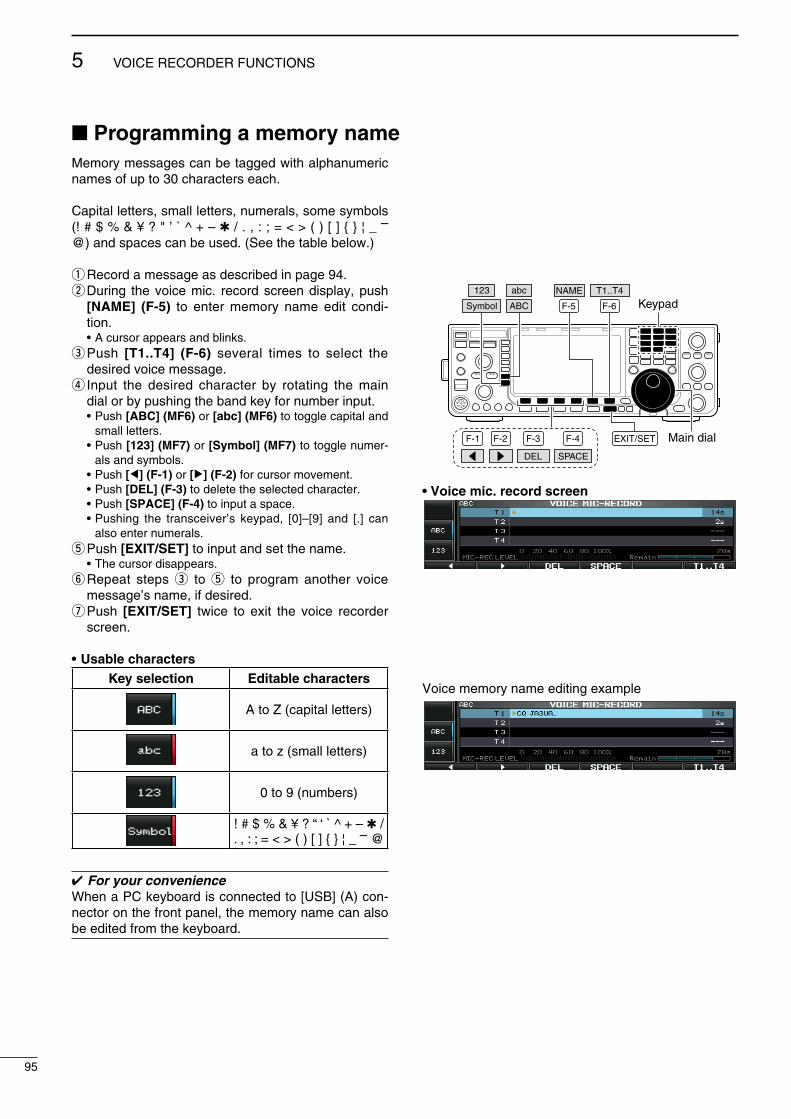
Programming a memory nameMemory messages can be tagged wth alphanumerc names of up to 30 characters each.
Captal letters, small letters, numerals, some symbols (! # $ % & ¥ ? " ’ ` ^ + – / . , : ; = < > ( ) [ ] ¦ _ – @) and spaces can be used. (See the table below.)
q Record a message as descrbed n page 94.w Durng the voce mc. record screen dsplay, push
[NAME] (F-5) to enter memory name edt cond-ton.
• A cursor appears and blnks.e Push [T1..T4] (F-6) several tmes to select the
desred voce message.r Input the desred character by rotatng the man
dal or by pushng the band key for number nput. • Push [ABC] (MF6) or [abc] (MF6) to toggle captal and
small letters. • Push [123] (MF7) or [Symbol] (MF7) to toggle numer-
als and symbols. • Push [Ω] (F-1) or [≈] (F-2) for cursor movement. • Push [DEL] (F-3) to delete the selected character. • Push [SPACE] (F-4) to nput a space. • Pushng the transcever’s keypad, [0]–[9] and [.] can
also enter numerals.t Push [EXIT/SET] to nput and set the name. • The cursor dsappears.y Repeat steps e to t to program another voce
message’s name, f desred.u Push [EXIT/SET] twce to ext the voce recorder
screen.
• Usable charactersKey selection Editable characters
A to Z (captal letters)
a to z (small letters)
0 to 9 (numbers)
! # $ % & ¥ ? “ ‘ ` ^ + – / . , : ; = < > ( ) [ ] ¦ _ – @
For your convenienceWhen a PC keyboard s connected to [USB] (A) con-nector on the front panel, the memory name can also be edted from the keyboard.
F-1 F-2 F-4F-3
DEL SPACE
F-5 F-6
EXIT/SET Main dial
Symbol ABC
123 abc T1..T4
KeypadNAME
• Voice mic. record screen
Voce memory name edtng example
95
5 VOICE RECORDER FUNCTIONS
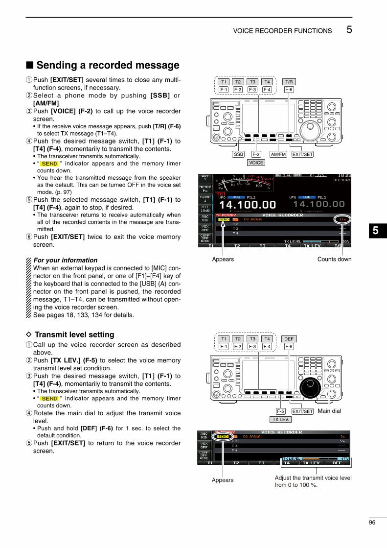
Sending a recorded messageq Push [EXIT/SET] several tmes to close any mult-
functon screens, f necessary.w Select a phone mode by pushng [SSB] or
[AM/FM].e Push [VOICE] (F-2) to call up the voce recorder
screen. • If the receve voce message appears, push [T/R] (F-6)
to select TX message (T1–T4).r Push the desred message swtch, [T1] (F-1) to
[T4] (F-4), momentarly to transmt the contents. • The transcever transmts automatcally. • “ ” ndcator appears and the memory tmer
counts down. • You hear the transmtted message from the speaker
as the default. Ths can be turned OFF n the voce set mode. (p. 97)
t Push the selected message swtch, [T1] (F-1) to [T4] (F-4), agan to stop, f desred.
• The transcever returns to receve automatcally when all of the recorded contents n the message are trans-mtted.
y Push [EXIT/SET] twce to ext the voce memory screen.
For your informationWhen an external keypad s connected to [MIC] con-nector on the front panel, or one of [F1]−[F4] key of the keyboard that s connected to the [USB] (A) con-nector on the front panel s pushed, the recorded message, T1–T4, can be transmtted wthout open-ng the voce recorder screen.See pages 18, 133, 134 for detals.
D Transmit level settingq Call up the voce recorder screen as descrbed
above.w Push [TX LEV.] (F-5) to select the voce memory
transmt level set condton.e Push the desred message swtch, [T1] (F-1) to
[T4] (F-4), momentarly to transmt the contents. • The transcever transmts automatcally. • “ ” ndcator appears and the memory tmer
counts down.r Rotate the man dal to adjust the transmt voce
level. • Push and hold [DEF] (F-6) for 1 sec. to select the
default condton.t Push [EXIT/SET] to return to the voce recorder
screen.
F-1 F-2 F-4F-3
F-2
F-6
EXIT/SET
T3 T/RT4T2T1
SSB AM/FM
VOICE
Appears Counts down
F-1 F-2 F-4F-3
T3 T4T2T1
F-5
F-6
EXIT/SET Main dialTX LEV.
DEF
Appears Adjust the transmit voice levelfrom 0 to 100 %.
96
5VOICE RECORDER FUNCTIONS
1
2
3
4
5
6
7
8
9
10
11
12
13
14
15
16
17
18
19
20
21
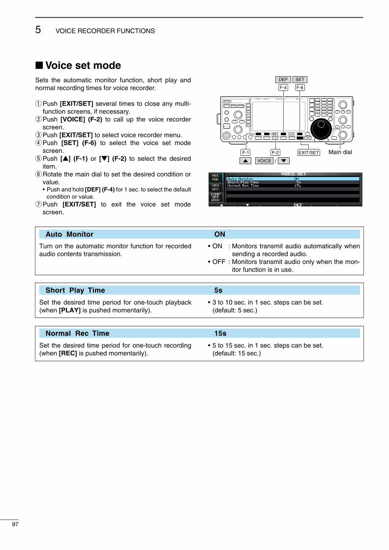
Voice set modeSets the automatc montor functon, short play and normal recordng tmes for voce recorder.
q Push [EXIT/SET] several tmes to close any mult-functon screens, f necessary.
w Push [VOICE] (F-2) to call up the voce recorder screen.
e Push [EXIT/SET] to select voce recorder menu.r Push [SET] (F-6) to select the voce set mode
screen.t Push [Y] (F-1) or [Z] (F-2) to select the desred
tem.y Rotate the man dal to set the desred condton or
value. • Push and hold [DEF] (F-4) for 1 sec. to select the default
condton or value.u Push [EXIT/SET] to ext the voce set mode
screen.
F-1 F-2
F-4 F-6
EXIT/SET Main dial
DEF SET
VOICE /
Auto Monitor ON
Turn on the automatc montor functon for recorded audo contents transmsson.
• ON : Montors transmt audo automatcally when sendng a recorded audo.
• OFF : Montors transmt audo only when the mon-tor functon s n use.
Short Play Time 5s
Set the desred tme perod for one-touch playback (when [PLAY] s pushed momentarly).
• 3 to 10 sec. n 1 sec. steps can be set. (default: 5 sec.)
Normal Rec Time 15s
Set the desred tme perod for one-touch recordng (when [REC] s pushed momentarly).
• 5 to 15 sec. n 1 sec. steps can be set. (default: 15 sec.)
97
5 VOICE RECORDER FUNCTIONS

Saving a voice message into the USB-MemoryD Saving the received audio memoryThe recorded RX memory contents can be saved nto the USB-Memory.
q Durng voce recorder RX memory screen dsplay, push [SAVE] (F-5) to select voce fle save screen.
• Prevously selected screen, TX or RX memory, s ds-played. If the TX message (T1–T4) appears, push [T/R] (F-6) to select RX message.
w Change the followng condtons f desred.
• File name: z Push [EDIT] (F-4) to select fle name edt con-
dton. • Push [DIR/FILE] (F-1) several tmes to select the
fle name, f necessary. x Push [ABC] (MF6), [123] (MF7) or [Symbol]
(MF7) to select the character group, then rotate the man dal to select the character.
• [ABC] (MF6) : A to Z (captal letters); [123] (MF7): 0 to 9 (numerals); [Symbol] (MF7): ! # $ % & ’ ` ^ – ( ) _ – @ can be selected.
• Push [Ω] (F-1) to move the cursor left, push [≈] (F-2) to move the cursor rght, push [DEL] (F-3) to delete a character and push [SPACE] (F-4) to nsert a space.
c Push [EXIT/SET] to set the fle name.
• Saving location z Push [DIR/FILE] (F-1) to select tree vew
screen. x Select the desred drectory or folder n the
USB-Memory. • Push [Ω ≈] (F-4) to select the upper drectory. • Push [Y] (F-2) or [Z] (F-3) to select folder n the
same drectory. • Push and hold [Ω ≈] (F-4) for 1 sec. to select a
folder n the drectory. • Push [REN] (MF5) to rename the folder. • Push and hold [DEL] (MF6) for 1 sec. to delete
the folder. • Push and hold [MAKE] (MF7) for 1 sec. to mak-
ng a new folder. (Edt the name wth the same manner as the “• Fle name” above.)
c Push [DIR/FILE] (F-1) twce to select the fle name.
e Push [SAVE] (F-5). • After the savng s completed, return to voce recorder
RX memory screen automatcally.
D Saving the TX memoryThe TX memory contents can also be saved nto the USB-Memory. However, the contents are saved wth the message lst, set mode condtons, etc. at the same tme. See page 139 for detals.
The USB-Memory s not suppled by Icom.
EDIT
F-4
SAVE
F-6
F-5
T/R
F-1 F-2 F-4F-3
DEL SPACE
Symbol ABC
123
F-1 EXIT/SET
DIR/FILE
Main dial
• Voice recorder RX memory screen
• Voice file save screen— file name edit
F-2 F-4F-3
REN DELMAKE
• While saving
When a PC keyboard s connected to the [USB] con-nector on the front panel, the file name can also be edted from the keyboard. In ths case, a USB hub s requred.
98
5VOICE RECORDER FUNCTIONS
1
2
3
4
5
6
7
8
9
10
11
12
13
14
15
16
17
18
19
20
21

6
99
MEMORY OPERATION
Memory channelsThe transcever has 101 memory channels. The Memory mode s very useful to quckly change to often-used frequences.
All 101 memory channels are tunable, whch means the programmed frequency can be tuned temporarly wth the man dal, etc. n memory mode.
MEMORYCHANNEL
MEMORYCHANNELNUMBER
CAPABILITYTRANSFER
TO VFOOVER-
WRITINGCLEAR
Regular memory channels
1–99One frequency and one mode n each memory channel.
Yes Yes Yes
Scan edgememorychannels
P1, P2One frequency and one mode n each memory channel as scan edges for programmed scan.
Yes Yes No
Memory channel selectionD Using the [∫]/[√] keysq Push [VFO/MEMO] to select the memory mode.w Push [∫]/[√] several tmes to select the desred
memory channel. • Push and hold [∫]/[√] for contnuous scrollng. • [UP] and [DN] on the mcrophone can also be used.e To return to VFO mode, push [VFO/MEMO] agan.
D Using the keypadq Push [VFO/MEMO] to select the memory mode.w Push [F-INP ENT].e Enter the desred memory channel number usng
the keypad. • Enter 100 or 101 to select scan edge channel P1 or P2,
respectvely.r Push [∫] or [√] to set the memory channel.
[EXAMPLE]To select memory channel 3;- Push [F-INP ENT], [7 3], then push [∫] or [√].
To select memory channel 12;- Push [F-INP ENT], [1.8 1], [3.5 2], then push [∫] or
[√].
To select the scan edge channel P1;- Push [F-INP ENT], [1.8 1], [50 0], [50 0], then push
[∫] or [√].
To select the scan edge channel P2;- Push [F-INP ENT], [1.8 1], [50 0], [1.8 1], then push
[∫] or [√].
VFO/MEMO
VFO/MEMO
Keypad F-INP ENT
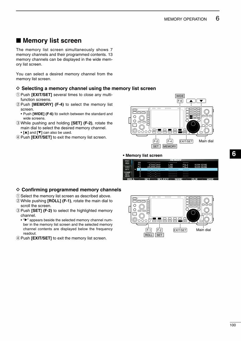
Memory list screenThe memory lst screen smultaneously shows 7 memory channels and ther programmed contents. 13 memory channels can be dsplayed n the wde mem-ory lst screen.
You can select a desred memory channel from the memory lst screen.
D Selecting a memory channel using the memory list screenq Push [EXIT/SET] several tmes to close any mult-
functon screens.w Push [MEMORY] (F-4) to select the memory lst
screen. • Push [WIDE] (F-6) to swtch between the standard and
wde screens.e Whle pushng and holdng [SET] (F-2), rotate the
man dal to select the desred memory channel. • [∫] and [√] can also be used.r Push [EXIT/SET] to ext the memory lst screen.
MEMORY
WIDE
SET
EXIT/SET Main dialF-2 F-4
F-6
• Memory list screen
D Confirming programmed memory channelsq Select the memory lst screen as descrbed above.w Whle pushng [ROLL] (F-1), rotate the man dal to
scroll the screen.e Push [SET] (F-2) to select the hghlghted memory
channel. • “≈” appears besde the selected memory channel num-
ber n the memory lst screen and the selected memory channel contents are dsplayed below the frequency readout.
r Push [EXIT/SET] to ext the memory lst screen.SET
EXIT/SET Main dialF-2
ROLL
F-1
100
6MEMORY OPERATION
1
2
3
4
5
6
7
8
9
10
11
12
13
14
15
16
17
18
19
20
21

Memory channel programmingMemory channel can be programmed n ether the VFO mode or the memory mode.
D Programming in the VFO modeq Set the desred frequency, operatng mode and fl-
ter wdth n the VFO mode.w Push [∫]/[√] several tmes to select the desred
memory channel. • The Memory lst screen s convenent for selectng the
desred channel. (p. 100) • Memory channel contents appear n the memory chan-
nel readout (below the frequency readout). • “--.---.--” appears f the selected memory channel s a
blank channel (and does not have any contents).e Push and hold [MW] for 1 sec. to program the ds-
played frequency, operatng mode, etc., nto the memory channel.
D Programming in the memory modeq Select the desred memory channel wth [∫]/[√] n
the memory mode. • Memory channel contents appear n the memory chan-
nel readout nstead of the frequency readout. • Nothng s dsplayed f the selected memory channel s
an empty channel.w Set the desred frequency and operatng mode. • To program a blank channel, use drect frequency entry
wth the keypad or memo pads, etc. (p. 28)e Push and hold [MW] for 1 sec. to program the ds-
played frequency and operatng mode nto the memory channel.
MW
[EXAMPLE]:Programmng 7.088 MHz/LSB nto memory channel 12.
Push for 1 sec.Beep
Beep Beep
7 3 SSB
MW
or
[EXAMPLE]:Programmng 21.280 MHz/USB nto memory channel 19.
Push for 1 sec.Beep
Beep Beep
SSB
MW
thenor 21 7
101
6 MEMORY OPERATION
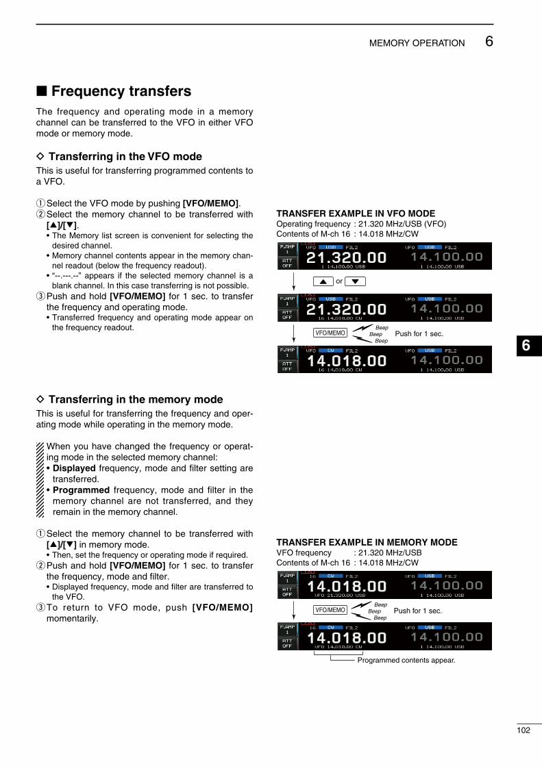
Frequency transfersThe frequency and operatng mode n a memory channel can be transferred to the VFO n ether VFO mode or memory mode.
D Transferring in the VFO modeThs s useful for transferrng programmed contents to a VFO.
q Select the VFO mode by pushng [VFO/MEMO].w Select the memory channel to be transferred wth
[∫]/[√]. • The Memory lst screen s convenent for selectng the
desred channel. • Memory channel contents appear n the memory chan-
nel readout (below the frequency readout). • “--.---.--” appears f the selected memory channel s a
blank channel. In ths case transferrng s not possble.e Push and hold [VFO/MEMO] for 1 sec. to transfer
the frequency and operatng mode. • Transferred frequency and operatng mode appear on
the frequency readout.
D Transferring in the memory modeThs s useful for transferrng the frequency and oper-atng mode whle operatng n the memory mode.
When you have changed the frequency or operat-ng mode n the selected memory channel:• Displayed frequency, mode and flter settng are
transferred.• Programmed frequency, mode and flter n the
memory channel are not transferred, and they reman n the memory channel.
q Select the memory channel to be transferred wth [∫]/[√] n memory mode.
• Then, set the frequency or operatng mode f requred.w Push and hold [VFO/MEMO] for 1 sec. to transfer
the frequency, mode and flter. • Dsplayed frequency, mode and flter are transferred to
the VFO.e To return to VFO mode, push [VFO/MEMO]
momentarly.
TRANSFER EXAMPLE IN VFO MODEOperatng frequency : 21.320 MHz/USB (VFO)Contents of M-ch 16 : 14.018 MHz/CW
Push for 1 sec.Beep
Beep Beep
or
VFO/MEMO
TRANSFER EXAMPLE IN MEMORY MODEVFO frequency : 21.320 MHz/USBContents of M-ch 16 : 14.018 MHz/CW
Push for 1 sec.Beep
Beep Beep
Programmed contents appear.
VFO/MEMO
102
6MEMORY OPERATION
1
2
3
4
5
6
7
8
9
10
11
12
13
14
15
16
17
18
19
20
21
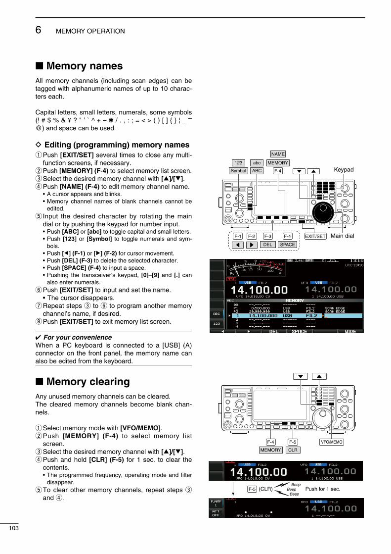
Memory namesAll memory channels (ncludng scan edges) can be tagged wth alphanumerc names of up to 10 charac-ters each.
Captal letters, small letters, numerals, some symbols (! # $ % & ¥ ? " ’ ` ^ + – / . , : ; = < > ( ) [ ] ¦ _ – @) and space can be used.
D Editing (programming) memory namesq Push [EXIT/SET] several tmes to close any mult-
functon screens, f necessary.w Push [MEMORY] (F-4) to select memory lst screen.e Select the desred memory channel wth [∫]/[√].r Push [NAME] (F-4) to edt memory channel name. • A cursor appears and blnks. • Memory channel names of blank channels cannot be
edted.t Input the desred character by rotatng the man
dal or by pushng the keypad for number nput. • Push [ABC] or [abc] to toggle captal and small letters. • Push [123] or [Symbol] to toggle numerals and sym-
bols. • Push [Ω] (F-1) or [≈] (F-2) for cursor movement. • Push [DEL] (F-3) to delete the selected character. • Push [SPACE] (F-4) to nput a space. • Pushng the transcever’s keypad, [0]–[9] and [.] can
also enter numerals.y Push [EXIT/SET] to nput and set the name. • The cursor dsappears.u Repeat steps e to y to program another memory
channel’s name, f desred.i Push [EXIT/SET] to ext memory lst screen.
For your convenienceWhen a PC keyboard s connected to a [USB] (A) connector on the front panel, the memory name can also be edted from the keyboard.
Memory clearingAny unused memory channels can be cleared. The cleared memory channels become blank chan-nels.
q Select memory mode wth [VFO/MEMO].w Push [MEMORY] (F-4) to select memory lst
screen.e Select the desred memory channel wth [∫]/[√].r Push and hold [CLR] (F-5) for 1 sec. to clear the
contents. • The programmed frequency, operatng mode and flter
dsappear.t To clear other memory channels, repeat steps e
and r.
F-1 F-2 F-4F-3
DEL SPACE
F-4
EXIT/SET Main dial
Symbol ABC
123 abc
KeypadMEMORY
NAME
F-5F-4
CLR
VFO/MEMO
MEMORY
Push for 1 sec.Beep
Beep Beep
(CLR)F-5
103
6 MEMORY OPERATION

Memo padsThe transcever has a memo pad functon to store frequency and operatng mode for easy wrtng and recallng. The memo pads are separate from the memory channels.
The default number of memo pads s 5. If desred, however, ths can be ncreased to 10 n the set mode. (p. 132)
Memo pads are convenent when you want to mem-orze a frequency and operatng mode temporarly, such as when you fnd a DX staton n a ple-up, or when a desred staton s busy for a long tme and you want to temporarly search for other statons.
Use the transcever’s memo pads nstead of relyng on hastly scrbbled notes that are easly msplaced.
MP-RMP-W
D Writing frequencies and operating modes into memo padsYou can store the readout frequency and operatng mode by pushng [MP-W].
When you store the 6th frequency and operatng mode, the oldest stored entres are automatcally erased, to make room for the new settngs.
Each memo pad must have ts own unque comb-naton of frequency and operatng mode; memo pads havng dentcal settngs cannot be wrtten.
MP-W
Newest
Erased
Oldest
In this example, 21.276 MHz (USB) will be erasedwhen 7.067 MHz (LSB) is written.
D Calling up a frequency and operating mode from a memo padYou can call up the desred contents of a memo pad by pushng [MP-R] several tmes.• Both VFO and memory modes can be used.• The frequency and operatng mode are called up, startng
from the most recently wrtten.
When you call up the memo pads wth [MP-R], the prevously dsplayed frequency and operatng mode are automatcally stored n a temporary pad. The tem-porary pad can be recalled by pushng [MP-R] sev-eral tmes.• You may thnk there are 6 memo pads because 6 dfferent
frequences (5 are n memo pads and 1 s n the tempo-rary pad) are called up by [MP-R].
If you change the frequency or operatng mode called up from a memo pad wth the man dal, etc., those n the temporary pad are erased.
MP-R
Newest
Oldest
MEMO PADS
MP-R
104
6MEMORY OPERATION
1
2
3
4
5
6
7
8
9
10
11
12
13
14
15
16
17
18
19
20
21

Scan types
PROGRAMMED SCANRepeatedly scans between two scan edge frequencies (scan edge memory channels P1 and P2).
This scan operates in the VFO mode.
SELECT MEMORY SCANRepeatedly scans all or one of 3 select memory channels.
∂F SCANRepeatedly scans within ∂F span area.
This scan operates in the memory mode.This scan operates in the memory mode.
This scan operates in both the VFO and memory modes.
Scan
Scan edge P1 or P2
Scan edge P2 or P1
Jump
MEMORY SCANRepeatedly scans all programmed memory channels.
Mch 11
Mch 51
Mch 22
Mch 31
Mch 4
Mch 63
Mch 71
Mch 991
Mch 11
Mch 51
Mch 22
Mch 31
Mch 4
Mch 63
Mch 71
Mch 991
Blank channel Blank channel
ScanScan
–∂F frequency +∂F frequency
Start frequency
Jump
*“1,” “2” and “3” show that the channel is specified as the select memory.
*“1,” “2” and “3” show that the channel is specified as the select memory.
Preparation• ChannelsFor programmed scan: Program scan edge frequences nto scan edge mem-ory channels P1 and P2. (p. 101)
For ∂F scan:Set the ∂F span (∂F scan range) n the scan screen.
For memory scan:Program 2 or more memory channels except scan edge memory channels.
For select memory scan:Desgnate 2 or more memory channels as Select memory channels. To desgnate the channel as a Select memory channel, choose a memory channel, then push [SELECT] (F-3) n the scan screen (mem-ory mode) or n the memory lst screen.
• Scan resume ON/OFFYou can select the scan to resume or cancel when detect-ng a sgnal n the scan set mode. Scan resume ON/OFF must be set before performng a scan. See p. 106 for ON/OFF settng and scan resume condton detals.
• Scan speedScan speed can be selected from 2 levels, hgh or low, n the scan set mode. See p. 106 for detals.
• Squelch condition Scan starts with the squelch openFor programmed scan:
When the tuning step is 1 kHz or less:The scan contnues untl t s stopped manually— t does not pause* even f sgnals are detected.* The scan s paused when the squelch s closed and then
opened (scan resumes after 10 sec. has passed when the scan resume s ON; the scan s cancelled when the scan resume s OFF).
When the tuning step is more than 5 kHz:The scan pauses on each step when the scan resume s ON; not applcable when the scan resume s OFF.
For memory scan:Scan pauses on each channel when the scan resume s ON; not applcable when the scan resume s OFF.
Scan starts with squelch closedScan stops when a sgnal s detected.• If the scan resume s set to ON n the scan set mode, the
scan pauses for 10 sec. when detectng a sgnal, then resumes. When a sgnal dsappears whle scan s paused, scan resumes 2 sec. later.
• The scan functon can be used on the man read-out only.
• You can perform a scan whle operatng on a fre-quency usng the dualwatch or splt functons.
7
105
SCANS
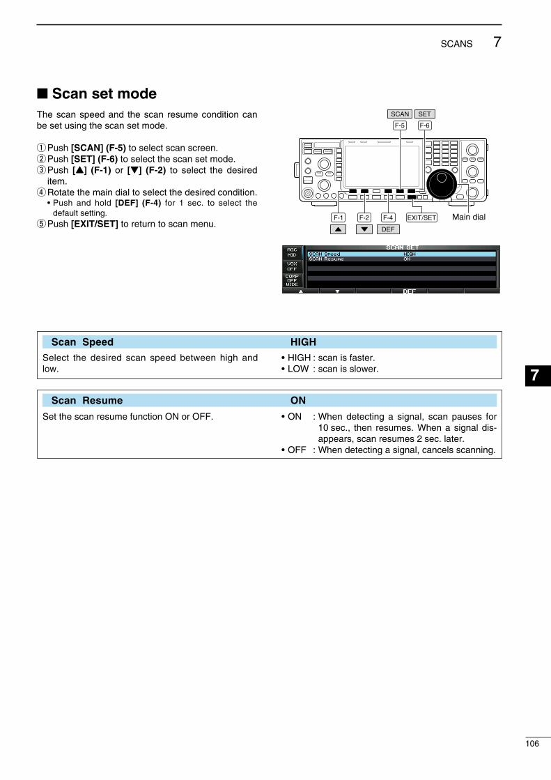
Scan set modeThe scan speed and the scan resume condton can be set usng the scan set mode.
q Push [SCAN] (F-5) to select scan screen.w Push [SET] (F-6) to select the scan set mode.e Push [Y] (F-1) or [Z] (F-2) to select the desred
tem.r Rotate the man dal to select the desred condton. • Push and hold [DEF] (F-4) for 1 sec. to select the
default settng.t Push [EXIT/SET] to return to scan menu.
F-1 F-2 F-4 EXIT/SET Main dialDEF
F-5 F-6
SETSCAN
Scan Speed HIGH
Select the desred scan speed between hgh and low.
• HIGH : scan s faster.• LOW : scan s slower.
Scan Resume ON
Set the scan resume functon ON or OFF. • ON : When detectng a sgnal, scan pauses for 10 sec., then resumes. When a sgnal ds-appears, scan resumes 2 sec. later.
• OFF : When detectng a sgnal, cancels scannng.
106
7SCANS
1
2
3
4
5
6
7
8
9
10
11
12
13
14
15
16
17
18
19
20
21
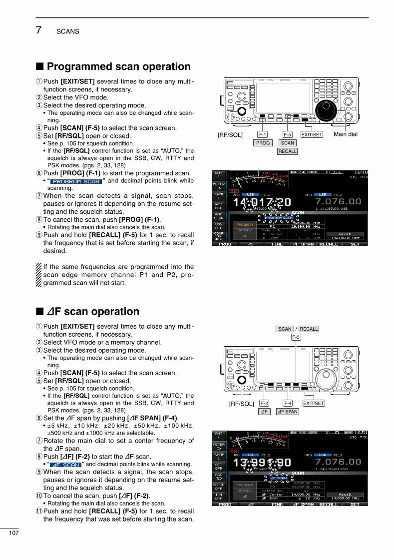
Programmed scan operationq Push [EXIT/SET] several tmes to close any mult-
functon screens, f necessary.w Select the VFO mode.e Select the desred operatng mode. • The operatng mode can also be changed whle scan-
nng.r Push [SCAN] (F-5) to select the scan screen.t Set [RF/SQL] open or closed. • See p. 105 for squelch condton. • If the [RF/SQL] control functon s set as “AUTO,” the
squelch s always open n the SSB, CW, RTTY and PSK modes. (pgs. 2, 33, 128)
y Push [PROG] (F-1) to start the programmed scan. • “ ” and decmal ponts blnk whle
scannng.u When the scan detects a sgnal, scan stops,
pauses or gnores t dependng on the resume set-tng and the squelch status.
i To cancel the scan, push [PROG] (F-1). • Rotatng the man dal also cancels the scan.o Push and hold [RECALL] (F-5) for 1 sec. to recall
the frequency that s set before startng the scan, f desred.
If the same frequences are programmed nto the scan edge memory channel P1 and P2, pro-grammed scan wll not start.
∂F scan operationq Push [EXIT/SET] several tmes to close any mult-
functon screens, f necessary.w Select VFO mode or a memory channel.e Select the desred operatng mode. • The operatng mode can also be changed whle scan-
nng.r Push [SCAN] (F-5) to select the scan screen.t Set [RF/SQL] open or closed. • See p. 105 for squelch condton. • If the [RF/SQL] control functon s set as “AUTO,” the
squelch s always open n the SSB, CW, RTTY and PSK modes. (pgs. 2, 33, 128)
y Set the ∂F span by pushng [∂F SPAN] (F-4). • ±5 kHz, ±10 kHz, ±20 kHz, ±50 kHz, ±100 kHz,
±500 kHz and ±1000 kHz are selectable.u Rotate the man dal to set a center frequency of
the ∂F span.i Push [∂F] (F-2) to start the ∂F scan. • “ ” and decmal ponts blnk whle scannng.o When the scan detects a sgnal, the scan stops,
pauses or gnores t dependng on the resume set-tng and the squelch status.
!0 To cancel the scan, push [∂F] (F-2). • Rotatng the man dal also cancels the scan.!1 Push and hold [RECALL] (F-5) for 1 sec. to recall
the frequency that was set before startng the scan.
F-1 F-5 EXIT/SET Main dial[RF/SQL]PROG SCAN
RECALL
F-2 F-4
∂F SPAN∂F
F-5
EXIT/SET[RF/SQL]
SCAN RECALL/
107
7 SCANS

Fine programmed scan/Fine ∂F scanIn fne scan (programmed or ∂F), the scan speed decreases when the squelch opens, but the trans-cever keeps scannng. The scannng tunng step shfts from 50 Hz to 10 Hz when the squelch opens.
q Push [EXIT/SET] several tmes to close any mult-functon screens, f necessary.
w Push [SCAN] (F-5) to select the scan screen.e Set for programmed scan or ∂F scan as descrbed
on the prevous page.r Push [PROG] (F-1) or [∂F] (F-2) to start a scan. • “ ” or “ ” and decmal
ponts blnk whle scannng.t Push [FINE] (F-3) to start a fne scan. • “ ” or “ ”
blnks nstead of “ ” or “ , ” respectvely.
y When the scan detects a sgnal, the scan speed decreases but scan does not stop.
u Push [PROG] (F-1) or [∂F] (F-2) to stop the scan; push [FINE] (F-3) to cancel the fne scan.
• Rotatng the man dal also cancels the scan.i Push and hold [RECALL] (F-5) for 1 sec. to recall
the frequency that s set before startng the scan, f desred.
F-1 F-5 EXIT/SET Main dialPROG SCAN
RECALL
F-3F-2
∂F FINE
108
7SCANS
1
2
3
4
5
6
7
8
9
10
11
12
13
14
15
16
17
18
19
20
21
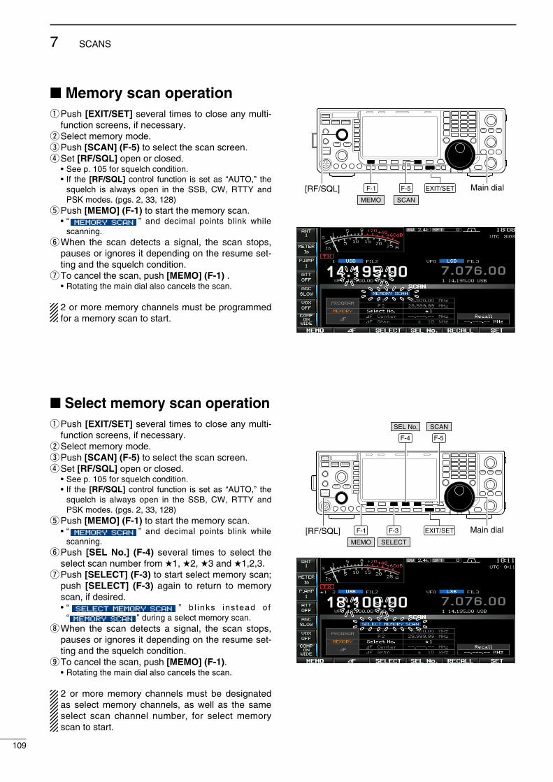
Memory scan operationq Push [EXIT/SET] several tmes to close any mult-
functon screens, f necessary.w Select memory mode.e Push [SCAN] (F-5) to select the scan screen.r Set [RF/SQL] open or closed. • See p. 105 for squelch condton. • If the [RF/SQL] control functon s set as “AUTO,” the
squelch s always open n the SSB, CW, RTTY and PSK modes. (pgs. 2, 33, 128)
t Push [MEMO] (F-1) to start the memory scan. • “ ” and decmal ponts blnk whle
scannng.y When the scan detects a sgnal, the scan stops,
pauses or gnores t dependng on the resume set-tng and the squelch condton.
u To cancel the scan, push [MEMO] (F-1) . • Rotatng the man dal also cancels the scan.
2 or more memory channels must be programmed for a memory scan to start.
Select memory scan operationq Push [EXIT/SET] several tmes to close any mult-
functon screens, f necessary.w Select memory mode.e Push [SCAN] (F-5) to select the scan screen.r Set [RF/SQL] open or closed. • See p. 105 for squelch condton. • If the [RF/SQL] control functon s set as “AUTO,” the
squelch s always open n the SSB, CW, RTTY and PSK modes. (pgs. 2, 33, 128)
t Push [MEMO] (F-1) to start the memory scan. • “ ” and decmal ponts blnk whle
scannng.yPush [SEL No.] (F-4) several tmes to select the
select scan number from 1, 2, 3 and 1,2,3.u Push [SELECT] (F-3) to start select memory scan;
push [SELECT] (F-3) agan to return to memory scan, f desred.
• “ ” b l nks ns tead o f “ ” durng a select memory scan.
i When the scan detects a sgnal, the scan stops, pauses or gnores t dependng on the resume set-tng and the squelch condton.
o To cancel the scan, push [MEMO] (F-1). • Rotatng the man dal also cancels the scan.
2 or more memory channels must be desgnated as select memory channels, as well as the same select scan channel number, for select memory scan to start.
F-1 F-5 EXIT/SET Main dial[RF/SQL]SCANMEMO
F-3
SELECT
F-1
F-4 F-5
EXIT/SET Main dial[RF/SQL]
SCAN
MEMO
SEL No.
109
7 SCANS
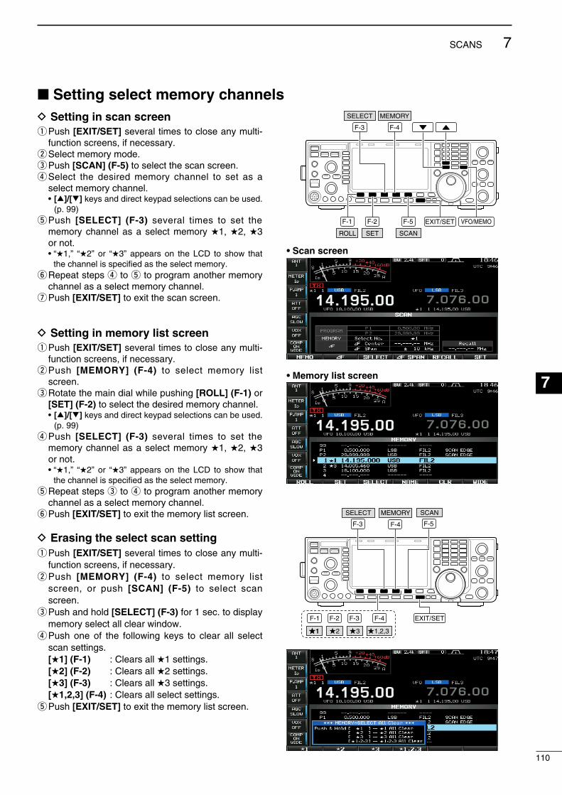
Setting select memory channelsD Setting in scan screenq Push [EXIT/SET] several tmes to close any mult-
functon screens, f necessary.w Select memory mode.e Push [SCAN] (F-5) to select the scan screen.r Select the desred memory channel to set as a
select memory channel. • [∫]/[√] keys and drect keypad selectons can be used.
(p. 99)t Push [SELECT] (F-3) several tmes to set the
memory channel as a select memory 1, 2, 3 or not.
• “1,” “2” or “3” appears on the LCD to show that the channel s specfed as the select memory.
y Repeat steps r to t to program another memory channel as a select memory channel.
u Push [EXIT/SET] to ext the scan screen.
D Setting in memory list screenq Push [EXIT/SET] several tmes to close any mult-
functon screens, f necessary.w Push [MEMORY] (F-4) to select memory lst
screen.e Rotate the man dal whle pushng [ROLL] (F-1) or
[SET] (F-2) to select the desred memory channel. • [∫]/[√] keys and drect keypad selectons can be used.
(p. 99)r Push [SELECT] (F-3) several tmes to set the
memory channel as a select memory 1, 2, 3 or not.
• “1,” “2” or “3” appears on the LCD to show that the channel s specfed as the select memory.
t Repeat steps e to r to program another memory channel as a select memory channel.
y Push [EXIT/SET] to ext the memory lst screen.
D Erasing the select scan settingq Push [EXIT/SET] several tmes to close any mult-
functon screens, f necessary.w Push [MEMORY] (F-4) to select memory lst
screen, or push [SCAN] (F-5) to select scan screen.
e Push and hold [SELECT] (F-3) for 1 sec. to dsplay memory select all clear wndow.
r Push one of the followng keys to clear all select scan settngs.
[1] (F-1) : Clears all 1 settngs. [2] (F-2) : Clears all 2 settngs. [3] (F-3) : Clears all 3 settngs. [1,2,3] (F-4) : Clears all select settngs.t Push [EXIT/SET] to ext the memory lst screen.
EXIT/SET
F-3
F-5F-1 F-2 VFO/MEMO
SCAN
SELECT
F-4
MEMORY
ROLL SET
• Scan screen
• Memory list screen
F-5
SCAN
F-3
SELECT
F-1 F-2 F-3
11 2 3
F-4
1,2,3
F-4
MEMORY
EXIT/SET
110
7SCANS
1
2
3
4
5
6
7
8
9
10
11
12
13
14
15
16
17
18
19
20
21
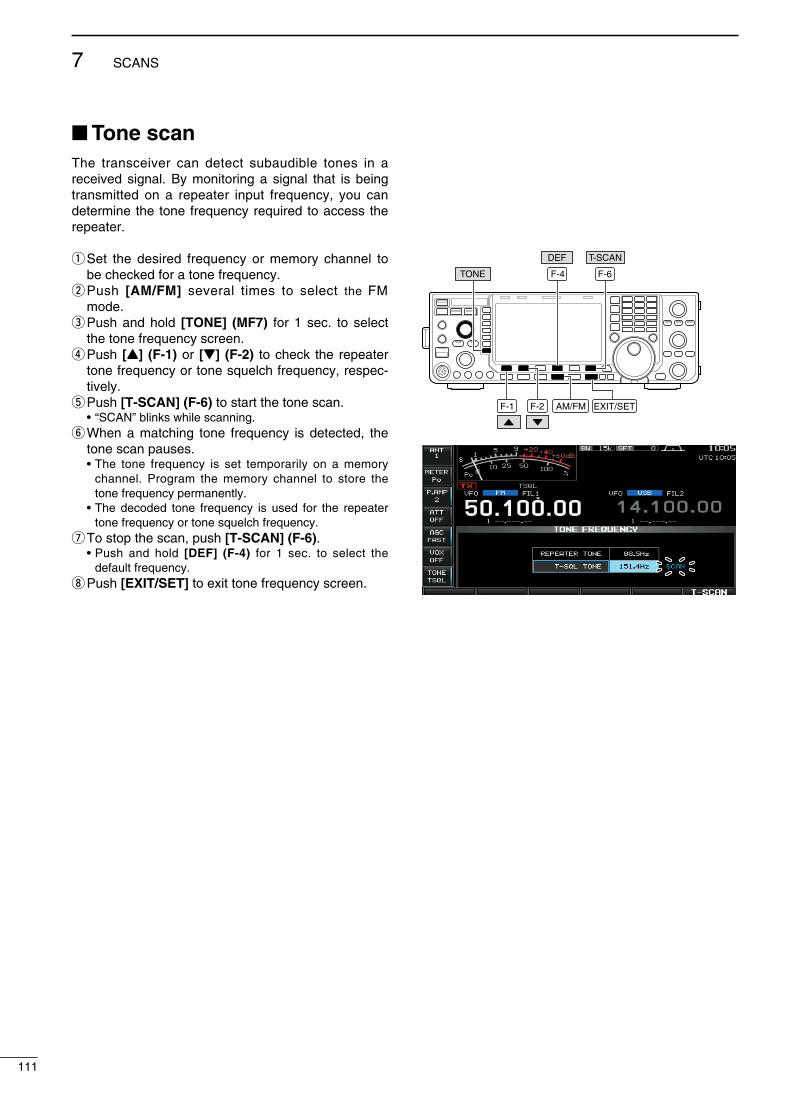
Tone scanThe transcever can detect subaudble tones n a receved sgnal. By montorng a sgnal that s beng transmtted on a repeater nput frequency, you can determne the tone frequency requred to access the repeater.
q Set the desred frequency or memory channel to be checked for a tone frequency.
w Push [AM/FM] several tmes to select the FM mode.
e Push and hold [TONE] (MF7) for 1 sec. to select the tone frequency screen.
r Push [Y] (F-1) or [Z] (F-2) to check the repeater tone frequency or tone squelch frequency, respec-tvely.
t Push [T-SCAN] (F-6) to start the tone scan. • “SCAN” blnks whle scannng.y When a matchng tone frequency s detected, the
tone scan pauses. • The tone frequency s set temporarly on a memory
channel. Program the memory channel to store the tone frequency permanently.
• The decoded tone frequency s used for the repeater tone frequency or tone squelch frequency.
u To stop the scan, push [T-SCAN] (F-6). • Push and hold [DEF] (F-4) for 1 sec. to select the
default frequency.i Push [EXIT/SET] to ext tone frequency screen.
F-1 F-2 EXIT/SETAM/FM
TONE
T-SCANDEF
F-4 F-6
111
7 SCANS

Automatic antenna selectionThe transcever covers 0.03–60 MHz over 10 bands. Each band key has a band memory whch can mem-orze a selected antenna (ANT1, ANT2, ANT1/RX antenna and ANT2/RX antenna). When you change the operatng frequency beyond a band, the prev-ously used antenna s automatcally selected. Ths functon s convenent when you use 2 or 3 antennas.
To use the band memory, select the set mode and confrm that “Auto” s selected as the [ANT] swtch opton. (p. 130)
• Antenna selection mode: “Auto” (default)The antenna tuner ON/OFF condton s also memo-rzed n the band memory.
[Example]: a 3.5/7 MHz antenna s connected to [ANT1], a 21/28/50 MHz antenna s connected to [ANT2]. When the antenna selector functon s set to “Auto,” an antenna s automatcally selected when the transcever changes bands.
• Antenna selection mode: “Manual”[ANT] (MF1) functons, however, band memory does not functon. In ths case, you must select an antenna manually.When usng an external antenna selector for more than 3 antennas (except for a receve antenna), “Manual” should be selected as the [ANT] swtch the set mode tem. (p. 130)
NOTE: When “Auto” or “Manual” s selected, the antenna tuner ON/OFF condton s consstent wth [ANT] (MF1).
• Antenna selection mode: “OFF”[ANT] (MF1) does not functon and [ANT1] s always selected.
3.5/7 MHzbands
21/28/50 MHzbands
RXonly
ANT1 ANT2
RX ANTIN
ANT
8
112
ANTENNA TUNER OPERATION
1
2
3
4
5
6
7
8
9
10
11
12
13
14
15
16
17
18
19
20
21
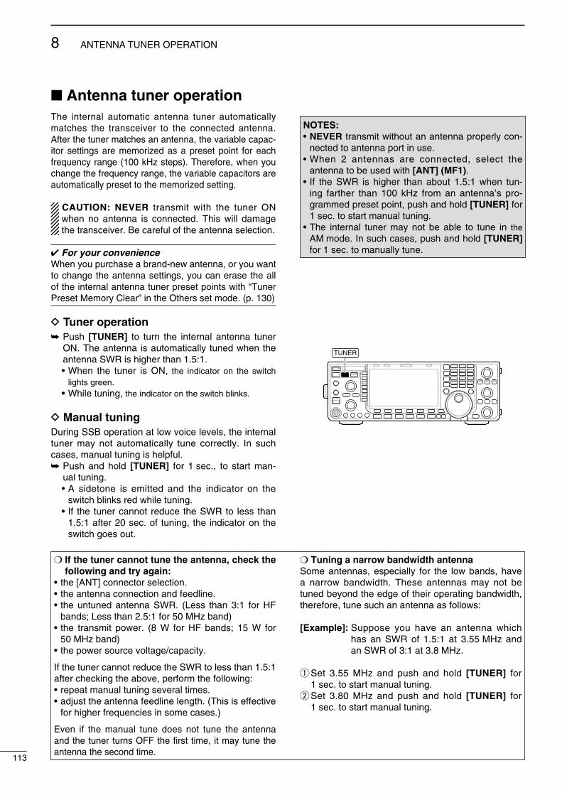
Antenna tuner operationThe nternal automatc antenna tuner automatcally matches the transcever to the connected antenna. After the tuner matches an antenna, the varable capac-tor settngs are memorzed as a preset pont for each frequency range (100 kHz steps). Therefore, when you change the frequency range, the varable capactors are automatcally preset to the memorzed settng.
CAUTION: NEVER transmt wth the tuner ON when no antenna s connected. Ths wll damage the transcever. Be careful of the antenna selecton.
For your convenienceWhen you purchase a brand-new antenna, or you want to change the antenna settngs, you can erase the all of the nternal antenna tuner preset ponts wth “Tuner Preset Memory Clear” n the Others set mode. (p. 130)
D Tuner operation Push [TUNER] to turn the nternal antenna tuner
ON. The antenna s automatcally tuned when the antenna SWR s hgher than 1.5:1.
• When the tuner s ON, the ndcator on the swtch lghts green.
• Whle tunng, the ndcator on the swtch blnks.
D Manual tuningDurng SSB operaton at low voce levels, the nternal tuner may not automatcally tune correctly. In such cases, manual tunng s helpful. Push and hold [TUNER] for 1 sec., to start man-
ual tunng. • A sdetone s emtted and the ndcator on the
swtch blnks red whle tunng. • If the tuner cannot reduce the SWR to less than
1.5:1 after 20 sec. of tunng, the ndcator on the swtch goes out.
NOTES:• NEVER transmt wthout an antenna properly con-
nected to antenna port n use.• When 2 antennas are connected, select the
antenna to be used wth [ANT] (MF1).• If the SWR s hgher than about 1.5:1 when tun-
ng farther than 100 kHz from an antenna’s pro-grammed preset pont, push and hold [TUNER] for 1 sec. to start manual tunng.
• The nternal tuner may not be able to tune n the AM mode. In such cases, push and hold [TUNER] for 1 sec. to manually tune.
TUNER
113
8 ANTENNA TUNER OPERATION
If the tuner cannot tune the antenna, check the following and try again:
• the [ANT] connector selecton.• the antenna connecton and feedlne.• the untuned antenna SWR. (Less than 3:1 for HF
bands; Less than 2.5:1 for 50 MHz band)• the transmt power. (8 W for HF bands; 15 W for
50 MHz band)• the power source voltage/capacty.
If the tuner cannot reduce the SWR to less than 1.5:1 after checkng the above, perform the followng:• repeat manual tunng several tmes.• adjust the antenna feedlne length. (Ths s effectve
for hgher frequences n some cases.)
Even f the manual tune does not tune the antenna and the tuner turns OFF the frst tme, t may tune the antenna the second tme.
Tuning a narrow bandwidth antennaSome antennas, especally for the low bands, have a narrow bandwdth. These antennas may not be tuned beyond the edge of ther operatng bandwdth, therefore, tune such an antenna as follows:
[Example]: Suppose you have an antenna whch has an SWR of 1.5:1 at 3.55 MHz and an SWR of 3:1 at 3.8 MHz.
q Set 3.55 MHz and push and hold [TUNER] for 1 sec. to start manual tunng.
w Set 3.80 MHz and push and hold [TUNER] for 1 sec. to start manual tunng.

Optional external tuner operation• AH-4 HF AUTOMATIC ANTENNA TUNERThe AH-4 matches the IC-7600 to a long wre antenna more than 7 m/23 ft long (3.5 MHz and above).• See p. 18 for the transcever and AH-4 connecton.• See the AH-4 nstructon manual for AH-4 nstalla-
ton and antenna connecton detals.
AH-4 setting example:
For mobile operation
For outdoor operation
Long wire
Optional AH-2bantenna element
R DANGER: HIGH VOLTAGE! NEVER touch the antenna element whle tunng
or transmttng.
NEVER operate the AH-4 wthout an antenna wre. The tuner and transcever wll be damaged.
NEVER operate the AH-4 when t s not grounded.
Transmttng before tunng may damage the trans-cever. Note that the AH-4 cannot tune when usng a ½λ long wre or multple of the operatng frequency.
When connectng the AH-4, the antenna connector assgnments are [ANT2] for the nternal tuner and [ANT1] for the AH-4. The antenna ndcator n the LCD dsplays “ANT1(EXT)” when the AH-4 s con-nected and selected.
• AH-4 operationTunng s requred for each frequency. Be sure to re-tune the antenna before transmttng when you change the frequency— even slghtly.
q Set the desred frequency n an HF or 50 MHz band for use wth the AH-4.
• The AH-4 wll not operate on frequences outsde of ham bands.
w Push and hold [TUNER] for 1 sec. • The ndcator on the swtch blnks whle tunng.
TUNER
e The ndcator on the swtch lghts constantly when tunng s complete.
• When the connected wre cannot be tuned, the ndcator on the swtch goes out and the AH-4 s bypassed. At that pont the antenna wre connec-ton s to the transcever drectly, and not va the AH-4 antenna tuner.
r To bypass the AH-4 manually, push [TUNER].
NOTE: PTT tuner functon s also avalable. See p. 129 for detals.
• Antenna tuner of the IC-PW1/EUROWhen usng an external antenna tuner such as the IC-PW1/EURO’s tuner, tune wth the external antenna tuner, whle the nternal tuner s turned OFF. After tun-ng s completed, turn the nternal tuner ON.Otherwse, both tuners tune smultaneously and cor-rect tunng may not be obtaned.See the nstructon manual ncluded wth each antenna tuner for ther respectve operatons.
114
8ANTENNA TUNER OPERATION
1
2
3
4
5
6
7
8
9
10
11
12
13
14
15
16
17
18
19
20
21
• Automatic tuner start (HF bands only)If you want to deactvate the tuner under condtons of VSWR 1.5:1 or less, use the auto tuner start func-ton and turn the tuner OFF. Ths functon actvates the tuner automatcally when the SWR s hgh, and s controlled n set mode. (p. 129).• The tuner may not be actvated f the TX power s not
output stably longer than the specfed tme perod as the SSB or CW mode operaton.
• PTT tuner startTunng of the nternal*/external antenna tuner starts when [PTT] s pushed on a new frequency (more than 1% away from the last-tuned frequency). Ths func-ton removes the “push and hold [TUNER]” operaton and actvates for the frst transmsson on a new fre-quency.*Tunng starts f the nternal antenna tuner s ON.Ths functon s turned ON n set mode. (p. 129).

9
115
CLOCK AND TIMERS
Clock set mode
F-1 F-2 F-4
F-6
EXIT/SET Main dial
SET
TIMECLOCK /
The IC-7600 has a bult-n calendar and 24-hour clock (accuracy ±75 sec. per month) wth daly power ON/OFF tmer functons. Before operatng these tmer functons, set the current date and tme.
q Push [EXIT/SET] several tmes to close mult-func-ton screen, f necessary.
w Push [SET] (F-6) to select the set mode menu screen.e Push [TIME] (F-4) to select the tme set mode.r Push [CLOCK] (F-1) to select the clock set mode.t Push [Y] (F-1) or [Z] (F-2) to select the desred
tem, then rotate the man dal to set or select the desred value or condton.
• Pushng [Ω≈] (F-3) may be necessary for some tems. • Push and hold [DEF] (F-4) to select a default condton
or value.y Push [EXIT/SET] to ext the tme set mode.
Date 2000 – 1 – 1 ( Sat )Sets the date. z Push [Ω ≈] (F-3) to select between the year and the
month/day, then rotate the man dal to select them. • The date settng and “DATE-set Push [SET]” ndca-
tors blnk.x Push [SET] (F-5) to set the date.
Time (Now) 0:00Sets the local tme. z Rotate the man dal to set the local tme.
• The tme settng and “TIME-set Push [SET]” ndca-tors blnk.
x Push [SET] (F-5) to set the tme.
CLOCK2 Function ONTurns the CLOCK2 ndcator ON and OFF.CLOCK2 s convenent to dsplay UTC or other country’s local tme, etc.
• ON : The CLOCK2 ndcator s dsplayed below the local tme dsplay.
• OFF : The CLOCK2 ndcator does not dsplay.
CLOCK2 Offset ± 0:00Sets the desred off-set tme perod for CLOCK2 ds-play wthn –24:00 to +24:00 n 5 mn. steps.
CLOCK2 Name UTCSets the desred 3-character name for CLOCK2.Captal letters, small letters, numerals, some sym-bols (! # $ % & ¥ ? " ’ ` ^ + – ⁄ . , : ; = < > ( ) [ ] ¦ _ – @) and spaces can be used.
z Push [EDIT] (F-5) to select the name edt condton. • The cursor under the 1st character blnks.x Push [ABC]/[abc] (MF6) or [123]/[Symbol]
(MF7) to select the character group, then rotate the man dal to select the character.
• Push [ABC] or [abc] to toggle captal and small letters. • Push [123] or [Symbol] to toggle numerals and symbols. • Push [Ω] (F-1) or [≈] (F-2) for cursor movement. • Push [DEL] (F-3) to delete the selected character. • Push [SPACE] (F-4) to nput a space. • Pushng the transcever’s keypad, [0]–[9] and [.] can
also enter numerals.c Push [EXIT/SET] to set the name.
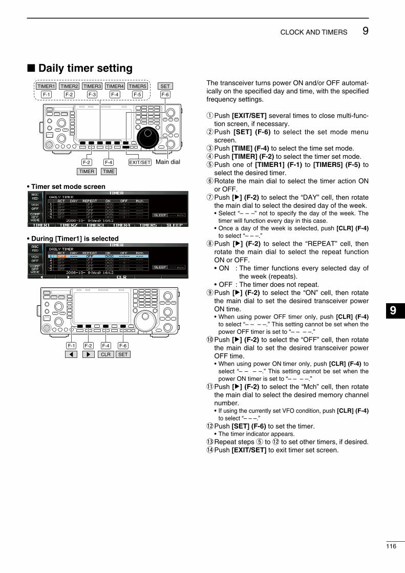
116
9CLOCK AND TIMERS
1
2
3
4
5
6
7
8
9
10
11
12
13
14
15
16
17
18
19
20
21
Daily timer setting
F-1 F-2 F-4F-3 F-5
TIMER2TIMER1 TIMER5TIMER4TIMER3
F-2 F-4
F-6
TIME
EXIT/SET Main dial
SET
TIMER
• Timer set mode screen
• During [Timer1] is selected
F-1 F-2 F-4 F-6
SETCLR
The transcever turns power ON and/or OFF automat-cally on the specfed day and tme, wth the specfed frequency settngs.
q Push [EXIT/SET] several tmes to close mult-func-ton screen, f necessary.
w Push [SET] (F-6) to select the set mode menu screen.
e Push [TIME] (F-4) to select the tme set mode.r Push [TIMER] (F-2) to select the tmer set mode.t Push one of [TIMER1] (F-1) to [TIMER5] (F-5) to
select the desred tmer.y Rotate the man dal to select the tmer acton ON
or OFF.u Push [≈] (F-2) to select the “DAY” cell, then rotate
the man dal to select the desred day of the week. • Select “– – –” not to specfy the day of the week. The
tmer wll functon every day n ths case. • Once a day of the week s selected, push [CLR] (F-4)
to select “– – –.” i Push [≈] (F-2) to select the “REPEAT” cell, then
rotate the man dal to select the repeat functon ON or OFF.
• ON : The tmer functons every selected day of the week (repeats).
• OFF : The tmer does not repeat.o Push [≈] (F-2) to select the “ON” cell, then rotate
the man dal to set the desred transcever power ON tme.
• When usng power OFF tmer only, push [CLR] (F-4) to select “– – – –.” Ths settng cannot be set when the power OFF tmer s set to “– – – –.”
!0 Push [≈] (F-2) to select the “OFF” cell, then rotate the man dal to set the desred transcever power OFF tme.
• When usng power ON tmer only, push [CLR] (F-4) to select “– – – –.” Ths settng cannot be set when the power ON tmer s set to “– – – –.”
!1 Push [≈] (F-2) to select the “Mch” cell, then rotate the man dal to select the desred memory channel number.
• If usng the currently set VFO condton, push [CLR] (F-4) to select “– – –.”
!2 Push [SET] (F-6) to set the tmer. • The tmer ndcator appears.!3 Repeat steps t to !2 to set other tmers, f desred.!4 Push [EXIT/SET] to ext tmer set screen.
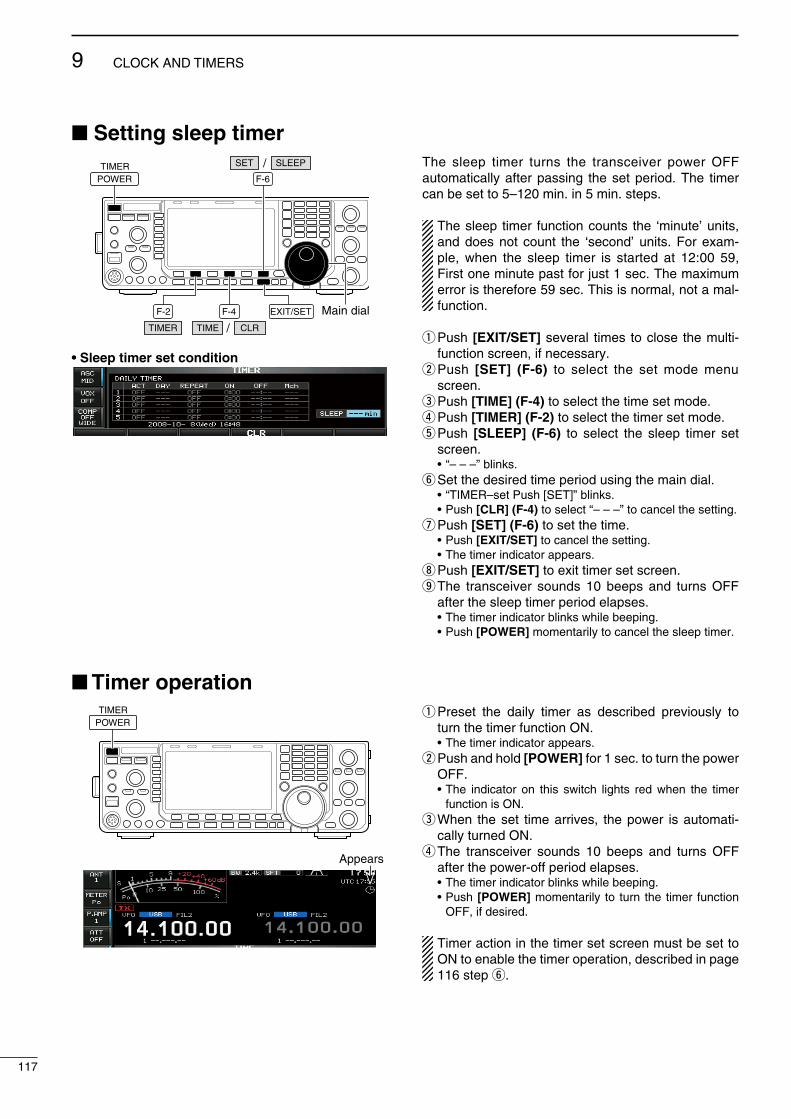
Setting sleep timer
F-2 F-4
F-6
EXIT/SET Main dialTIMER
SET SLEEP/
TIME CLR/
TIMERPOWER
• Sleep timer set condition
The sleep tmer turns the transcever power OFF automatcally after passng the set perod. The tmer can be set to 5–120 mn. n 5 mn. steps.
The sleep tmer functon counts the ‘mnute’ unts, and does not count the ‘second’ unts. For exam-ple, when the sleep tmer s started at 12:00 59, Frst one mnute past for just 1 sec. The maxmum error s therefore 59 sec. Ths s normal, not a mal-functon.
q Push [EXIT/SET] several tmes to close the mult-functon screen, f necessary.
w Push [SET] (F-6) to select the set mode menu screen.
e Push [TIME] (F-4) to select the tme set mode.r Push [TIMER] (F-2) to select the tmer set mode.t Push [SLEEP] (F-6) to select the sleep tmer set
screen. • “– – –” blnks.y Set the desred tme perod usng the man dal. • “TIMER–set Push [SET]” blnks. • Push [CLR] (F-4) to select “– – –” to cancel the settng.u Push [SET] (F-6) to set the tme. • Push [EXIT/SET] to cancel the settng. • The tmer ndcator appears.i Push [EXIT/SET] to ext tmer set screen.o The transcever sounds 10 beeps and turns OFF
after the sleep tmer perod elapses. • The tmer ndcator blnks whle beepng. • Push [POWER] momentarly to cancel the sleep tmer.
Timer operationTIMER
POWERq Preset the daly tmer as descrbed prevously to
turn the tmer functon ON. • The tmer ndcator appears.w Push and hold [POWER] for 1 sec. to turn the power
OFF. • The ndcator on ths swtch lghts red when the tmer
functon s ON.e When the set tme arrves, the power s automat-
cally turned ON.r The transcever sounds 10 beeps and turns OFF
after the power-off perod elapses. • The tmer ndcator blnks whle beepng. • Push [POWER] momentarly to turn the tmer functon
OFF, f desred.
Tmer acton n the tmer set screen must be set to ON to enable the tmer operaton, descrbed n page 116 step y.
117
9 CLOCK AND TIMERS
Appears
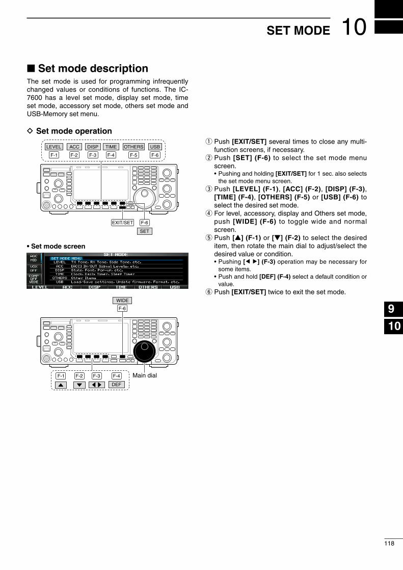
Set mode descriptionThe set mode s used for programmng nfrequently changed values or condtons of functons. The IC-7600 has a level set mode, dsplay set mode, tme set mode, accessory set mode, others set mode and USB-Memory set menu.
D Set mode operation
F-1 F-2 F-3 F-4 F-5 F-6
LEVEL OTHERSTIMEDISPACC
EXIT/SET
USB
SET
F-6
• Set mode screen
F-1 F-2 F-3 F-4
F-6
Main dial
WIDE
DEF
q Push [EXIT/SET] several tmes to close any mult-functon screens, f necessary.
w Push [SET] (F-6) to select the set mode menu screen.
• Pushng and holdng [EXIT/SET] for 1 sec. also selects the set mode menu screen.
e Push [LEVEL] (F-1), [ACC] (F-2), [DISP] (F-3), [TIME] (F-4), [OTHERS] (F-5) or [USB] (F-6) to select the desred set mode.
r For level, accessory, dsplay and Others set mode, push [WIDE] (F-6) to toggle wde and normal screen.
t Push [Y] (F-1) or [Z] (F-2) to select the desred tem, then rotate the man dal to adjust/select the desred value or condton.
• Pushng [Ω≈] (F-3) operaton may be necessary for some tems.
• Push and hold [DEF] (F-4) select a default condton or value.
y Push [EXIT/SET] twce to ext the set mode.
10
118
SET MODE
1
2
3
4
5
6
7
8
9
10
11
12
13
14
15
16
17
18
19
20
21

D Screen arrangement
• Set mode menu screen (p. 118)
• Level set mode (p. 120)
• ACC set mode (p. 124)
• Time set mode (p. 115)
• Display set mode (p. 126)
• Others set mode (p. 128)
• USB-Memory set menu (p. 136)
F-3
F-4
F-5
F-6F-2
F-1 F-2 F-3 F-4 F-5 F-6
119
10 SET MODE

Level set mode
SSB RX HPF/LPF – – – – – – –Sets the hgh-pass flter (100 to 2000 Hz) and low-pass flter (500 to 2400 Hz) of the receve audo n 100 Hz steps n the SSB mode. (default: OFF)
NOTE: When ths settng s actve, below 2 tems wll be reset to default value, ‘0.’
SSB RX Tone (Bass) 0Sets the bass level of the receve audo tone n the SSB mode from –5 to +5. (default: 0)
SSB RX Tone (Treble) 0Sets the treble level of the receve audo tone n the SSB mode from –5 to +5. (default: 0)
AM RX HPF/LPF – – – – – – –Sets the hgh-pass flter (100 to 2000 Hz) and low-pass flter (500 to 2400 Hz) of the receve audo n 100 Hz steps n the AM mode. (default: OFF)
NOTE: When ths settng s actve, below 2 tems wll be reset to default value, ‘0.’
AM RX Tone (Bass) 0Sets the bass level of the receve audo tone n the AM mode from –5 to +5. (default: 0)
AM RX Tone (Treble) 0Sets the treble level of the receve audo tone n the AM mode from –5 to +5. (default: 0)
FM RX HPF/LPF – – – – – – –Sets the hgh-pass flter (100 to 2000 Hz) and low-pass flter (500 to 2400 Hz) of the receve audo n 100 Hz steps n the FM mode. (default: OFF)
NOTE: When ths settng s actve, below 2 tems wll be reset to default value, ‘0.’
FM RX Tone (Bass) 0Sets the bass level of the receve audo tone n the FM mode from –5 to +5. (default: 0)
FM RX Tone (Treble) 0Sets the treble level of the receve audo tone n the FM mode from –5 to +5. (default: 0)
Contnued on the next page.
120
10SET MODE
1
2
3
4
5
6
7
8
9
10
11
12
13
14
15
16
17
18
19
20
21
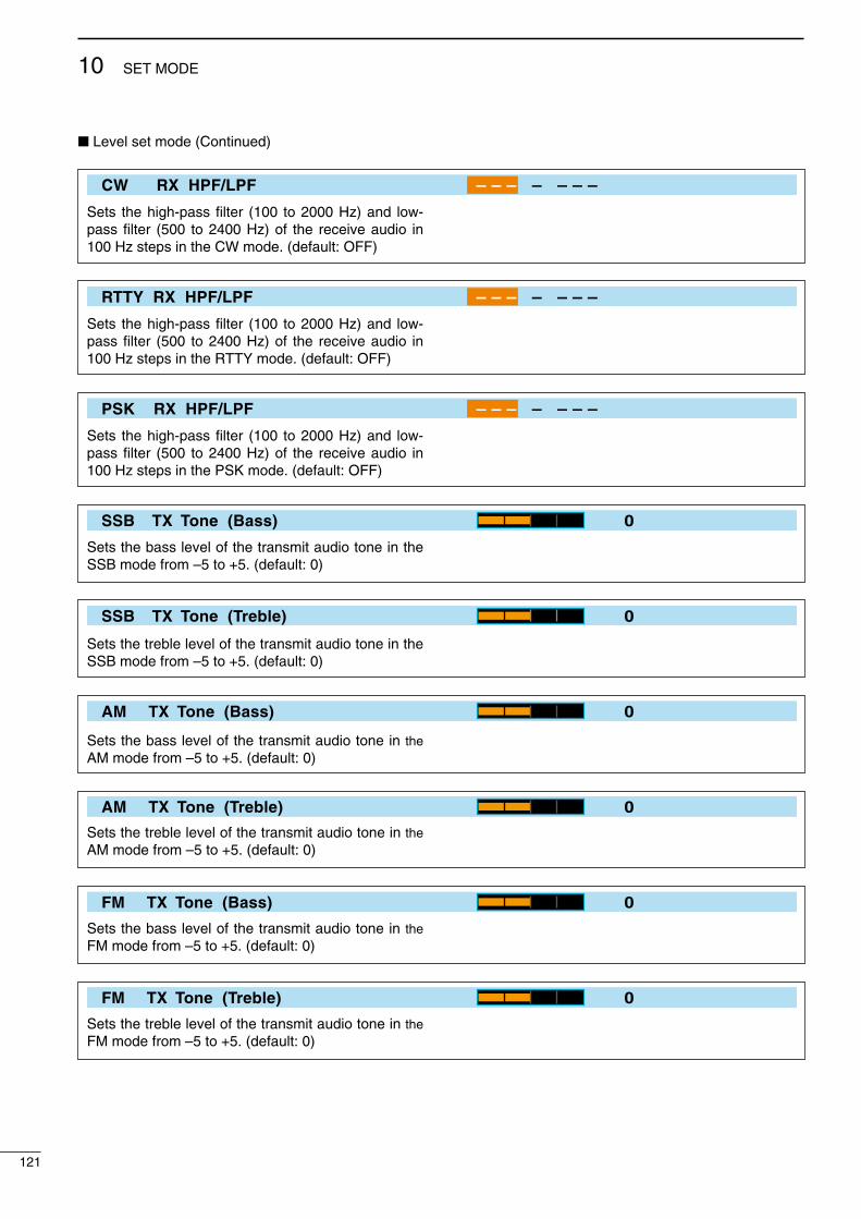
Level set mode (Contnued)
CW RX HPF/LPF – – – – – – –
Sets the hgh-pass flter (100 to 2000 Hz) and low-pass flter (500 to 2400 Hz) of the receve audo n 100 Hz steps n the CW mode. (default: OFF)
RTTY RX HPF/LPF – – – – – – –
Sets the hgh-pass flter (100 to 2000 Hz) and low-pass flter (500 to 2400 Hz) of the receve audo n 100 Hz steps n the RTTY mode. (default: OFF)
PSK RX HPF/LPF – – – – – – –
Sets the hgh-pass flter (100 to 2000 Hz) and low-pass flter (500 to 2400 Hz) of the receve audo n 100 Hz steps n the PSK mode. (default: OFF)
SSB TX Tone (Bass) 0
Sets the bass level of the transmt audo tone n the SSB mode from –5 to +5. (default: 0)
SSB TX Tone (Treble) 0
Sets the treble level of the transmt audo tone n the SSB mode from –5 to +5. (default: 0)
AM TX Tone (Bass) 0
Sets the bass level of the transmt audo tone n the AM mode from –5 to +5. (default: 0)
AM TX Tone (Treble) 0
Sets the treble level of the transmt audo tone n the AM mode from –5 to +5. (default: 0)
FM TX Tone (Bass) 0
Sets the bass level of the transmt audo tone n the FM mode from –5 to +5. (default: 0)
FM TX Tone (Treble) 0
Sets the treble level of the transmt audo tone n the FM mode from –5 to +5. (default: 0)
121
10 SET MODE

SSB TBW (WIDE) 100 – 2900
Sets the transmsson passband wdth to a wde set-tng by changng the lower and hgher cut-off fre-quences.
• Lower freq. : 100 (default), 200, 300 and 500 Hz• Hgher freq. : 2500, 2700, 2800 and
2900 Hz (default)
SSB TBW (MID) 300 – 2700
Sets the transmsson passband wdth to a mddle settng by changng the lower and hgher cut-off fre-quences.
• Lower freq. : 100, 200, 300 (default) and 500 Hz• Hgher freq. : 2500, 2700 (default), 2800
and 2900 Hz
SSB TBW (NAR) 500 – 2500
Sets the transmsson passband wdth to a narrow settng by changng the lower and hgher cut-off fre-quences.
• Lower freq. : 100, 200, 300 and 500 Hz (default)• Hgher freq. : 2500 (default), 2700, 2800
and 2900 Hz
Drive Gain 50%
Sets the drve gan level from 0% to 100% n 1% steps. (default: 50%)Whle talkng nto the mcrophone, keyng down or transmttng, rotate the man dal so that the ALC meter readng s between 30% to 50% of the ALC scale. (p. 37)
The drve gan s actve for all modes other than the SSB mode wth speech compressor OFF.
Speech Level 50%
Sets the voce syntheszer audo output level from 0% to 100% n 1% steps. (default: 50%)
Side Tone Level 50%
Sets the sdetone output level from 0% to 100% n 1% steps. (default: 50%)
Side Tone Level Limit ON
Turns the sdetone output level lmtng capablty ON or OFF. (default: ON)
When ths tem s set to ON, the CW sdetone s lnked to the [AF] control untl rotaton of the [AF] control reaches to the specfed level—further rota-ton wll not ncrease the volume of the CW sdet-ones.
• OFF : The CW sdetone level s lnked to the [AF] control.
• ON : The CW sdetone level s lmted wth the [AF] control.
Contnued on the next page.
122
10SET MODE
1
2
3
4
5
6
7
8
9
10
11
12
13
14
15
16
17
18
19
20
21

Level set mode (Contnued)
Beep Level 50%Sets the beep output level from 0% to 100% n 1% steps. (default: 50%)
Beep Level Limit ON
Turns the beep tone output level lmtng capablty ON or OFF for the confrmaton and band edge beep tones. (default: ON)
When ths tem s set to ON, the beep tones are lnked to the [AF] control untl rotaton of the [AF] control reaches to the specfed level—further rota-ton wll not ncrease the volume of the beep tones.
• OFF : Beep level s lnked to the [AF] control.• ON : Beep level s lmted wth the [AF] control.
123
10 SET MODE
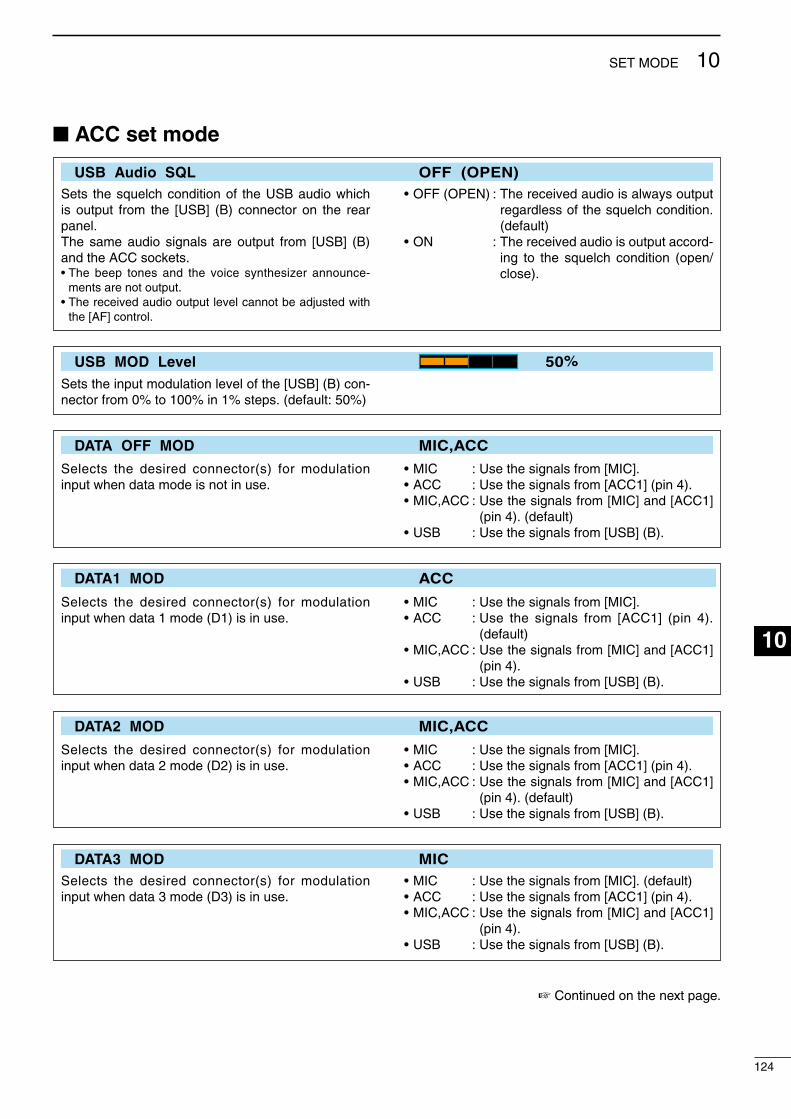
ACC set mode
USB Audio SQL OFF (OPEN)Sets the squelch condton of the USB audo whch s output from the [USB] (B) connector on the rear panel.The same audo sgnals are output from [USB] (B) and the ACC sockets.• The beep tones and the voce syntheszer announce-
ments are not output.• The receved audo output level cannot be adjusted wth
the [AF] control.
• OFF (OPEN) : The receved audo s always output regardless of the squelch condton. (default)
• ON : The receved audo s output accord-ng to the squelch condton (open/close).
USB MOD Level 50%
Sets the nput modulaton level of the [USB] (B) con-nector from 0% to 100% n 1% steps. (default: 50%)
DATA OFF MOD MIC,ACC
Selects the desred connector(s) for modulaton nput when data mode s not n use.
• MIC : Use the sgnals from [MIC].• ACC : Use the sgnals from [ACC1] (pn 4).• MIC,ACC : Use the sgnals from [MIC] and [ACC1]
(pn 4). (default)• USB : Use the sgnals from [USB] (B).
DATA1 MOD ACC
Selects the desred connector(s) for modulaton nput when data 1 mode (D1) s n use.
• MIC : Use the sgnals from [MIC].• ACC : Use the sgnals from [ACC1] (pn 4).
(default)• MIC,ACC : Use the sgnals from [MIC] and [ACC1]
(pn 4).• USB : Use the sgnals from [USB] (B).
DATA2 MOD MIC,ACC
Selects the desred connector(s) for modulaton nput when data 2 mode (D2) s n use.
• MIC : Use the sgnals from [MIC].• ACC : Use the sgnals from [ACC1] (pn 4).• MIC,ACC : Use the sgnals from [MIC] and [ACC1]
(pn 4). (default)• USB : Use the sgnals from [USB] (B).
DATA3 MOD MICSelects the desred connector(s) for modulaton nput when data 3 mode (D3) s n use.
• MIC : Use the sgnals from [MIC]. (default)• ACC : Use the sgnals from [ACC1] (pn 4).• MIC,ACC : Use the sgnals from [MIC] and [ACC1]
(pn 4).• USB : Use the sgnals from [USB] (B).
Contnued on the next page.
124
10SET MODE
1
2
3
4
5
6
7
8
9
10
11
12
13
14
15
16
17
18
19
20
21
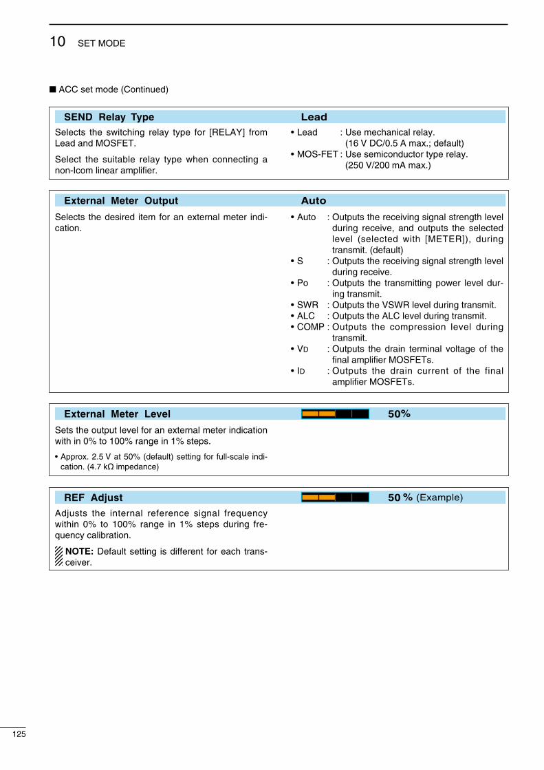
ACC set mode (Contnued)
SEND Relay Type LeadSelects the swtchng relay type for [RELAY] from Lead and MOSFET.
Select the sutable relay type when connectng a non-Icom lnear amplfer.
• Lead : Use mechancal relay. (16 V DC/0.5 A max.; default)
• MOS-FET : Use semconductor type relay. (250 V/200 mA max.)
External Meter Output Auto
Selects the desred tem for an external meter nd-caton.
• Auto : Outputs the recevng sgnal strength level durng receve, and outputs the selected level (selected wth [METER]), durng transmt. (default)
• S : Outputs the recevng sgnal strength level durng receve.
• Po : Outputs the transmttng power level dur-ng transmt.
• SWR : Outputs the VSWR level durng transmt.• ALC : Outputs the ALC level durng transmt.• COMP : Outputs the compresson level durng
transmt.• Vd : Outputs the dran termnal voltage of the
fnal amplfer MOSFETs.• Id : Outputs the dran current of the fnal
amplfer MOSFETs.
External Meter Level 50%
Sets the output level for an external meter ndcaton wth n 0% to 100% range n 1% steps.
• Approx. 2.5 V at 50% (default) settng for full-scale nd-caton. (4.7 kø mpedance)
REF Adjust 50 % (Example)
Adjusts the nternal reference sgnal frequency wthn 0% to 100% range n 1% steps durng fre-quency calbraton.
NOTE: Default settng s dfferent for each trans-cever.
125
10 SET MODE
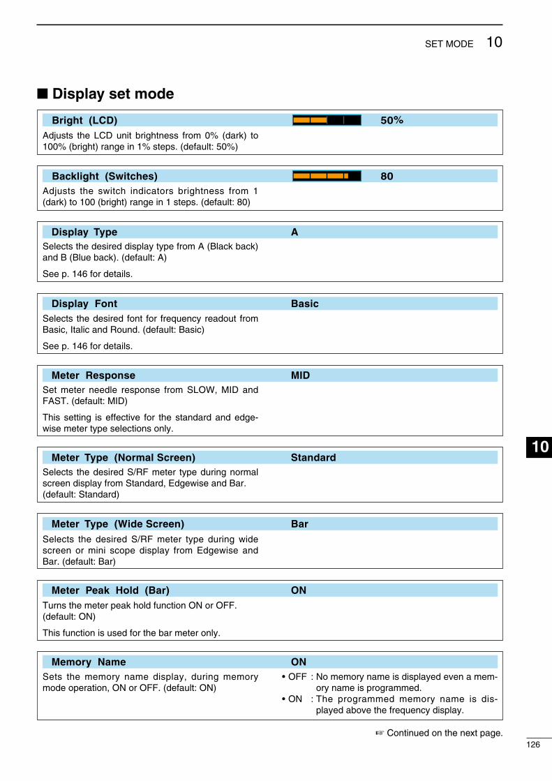
Display set mode
Bright (LCD) 50%
Adjusts the LCD unt brghtness from 0% (dark) to 100% (brght) range n 1% steps. (default: 50%)
Backlight (Switches) 80Adjusts the swtch ndcators brghtness from 1 (dark) to 100 (brght) range n 1 steps. (default: 80)
Display Type ASelects the desred dsplay type from A (Black back) and B (Blue back). (default: A)
See p. 146 for detals.
Display Font BasicSelects the desred font for frequency readout from Basc, Italc and Round. (default: Basc)
See p. 146 for detals.
Meter Response MIDSet meter needle response from SLOW, MID and FAST. (default: MID)
Ths settng s effectve for the standard and edge-wse meter type selectons only.
Meter Type (Normal Screen) StandardSelects the desred S/RF meter type durng normal screen dsplay from Standard, Edgewse and Bar.(default: Standard)
Meter Type (Wide Screen) BarSelects the desred S/RF meter type durng wde screen or mn scope dsplay from Edgewse and Bar. (default: Bar)
Meter Peak Hold (Bar) ONTurns the meter peak hold functon ON or OFF.(default: ON)
Ths functon s used for the bar meter only.
Memory Name ONSets the memory name dsplay, durng memory mode operaton, ON or OFF. (default: ON)
• OFF : No memory name s dsplayed even a mem-ory name s programmed.
• ON : The programmed memory name s ds-played above the frequency dsplay.
Contnued on the next page.126
10SET MODE
1
2
3
4
5
6
7
8
9
10
11
12
13
14
15
16
17
18
19
20
21
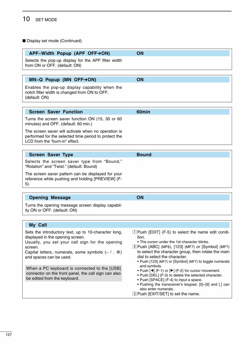
Dsplay set mode (Contnued)
APF−Width Popup (APF OFFON) ON
Selects the pop-up dsplay for the APF flter wdth from ON or OFF. (default: ON)
MN−Q Popup (MN OFFON) ON
Enables the pop-up dsplay capablty when the notch flter wdth s changed from ON to OFF. (default: ON)
Screen Saver Function 60min
Turns the screen saver functon ON (15, 30 or 60 mnutes) and OFF. (default: 60 mn.)
The screen saver wll actvate when no operaton s performed for the selected tme perod to protect the LCD from the “burn-n” effect.
Screen Saver Type BoundSelects the screen saver type from “Bound,” “Rotaton” and “Twst.” (default: Bound)
The screen saver pattern can be dsplayed for your reference whle pushng and holdng [PREVIEW] (F-5).
Opening Message ON
Turns the openng message screen dsplay capabl-ty ON or OFF. (default: ON)
My Call
Sets the ntroductory text, up to 10-character long, dsplayed n the openng screen.Usually, you set your call sgn for the openng screen.Captal letters, numerals, some symbols (– / . @) and spaces can be used.
When a PC keyboard s connected to the [USB] connector on the front panel, the call sgn can also be edted from the keyboard.
z Push [EDIT] (F-5) to select the name edt cond-ton.
• The cursor under the 1st character blnks.x Push [ABC] (MF6), [123] (MF7) or [Symbol] (MF7)
to select the character group, then rotate the man dal to select the character.
• Push [123] (MF7) or [Symbol] (MF7) to toggle numerals and symbols.
• Push [Ω] (F-1) or [≈] (F-2) for cursor movement. • Push [DEL] (F-3) to delete the selected character. • Push [SPACE] (F-4) to nput a space. • Pushng the transcever’s keypad, [0]–[9] and [.] can
also enter numerals.c Push [EXIT/SET] to set the name.
127
10 SET MODE
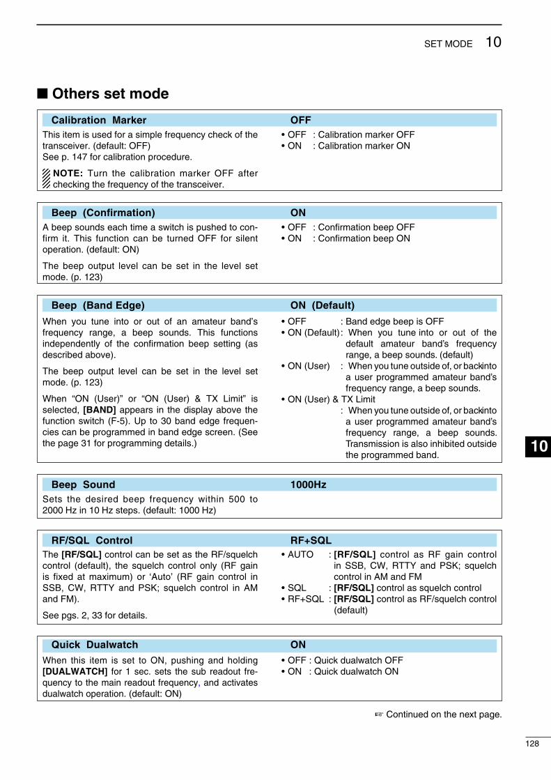
Others set mode
Calibration Marker OFFThs tem s used for a smple frequency check of the transcever. (default: OFF)See p. 147 for calbraton procedure.
NOTE: Turn the calbraton marker OFF after checkng the frequency of the transcever.
• OFF : Calbraton marker OFF• ON : Calbraton marker ON
Beep (Confirmation) ONA beep sounds each tme a swtch s pushed to con-frm t. Ths functon can be turned OFF for slent operaton. (default: ON)
The beep output level can be set n the level set mode. (p. 123)
• OFF : Confrmaton beep OFF• ON : Confrmaton beep ON
Beep (Band Edge) ON (Default)
When you tune nto or out of an amateur band’s frequency range, a beep sounds. Ths functons ndependently of the confrmaton beep settng (as descrbed above).
The beep output level can be set n the level set mode. (p. 123)
When “ON (User)” or “ON (User) & TX Lmt” s selected, [BAND] appears n the dsplay above the functon swtch (F-5). Up to 30 band edge frequen-ces can be programmed n band edge screen. (See the page 31 for programmng detals.)
• OFF : Band edge beep s OFF• ON (Default) : When you tune nto or out of the
default amateur band’s frequency range, a beep sounds. (default)
• ON (User) : When you tune outsde of, or back nto a user programmed amateur band’s frequency range, a beep sounds.
• ON (User) & TX Lmt : When you tune outsde of, or back nto
a user programmed amateur band’s frequency range, a beep sounds. Transmsson s also nhbted outsde the programmed band.
Beep Sound 1000HzSets the desred beep frequency wthn 500 to 2000 Hz n 10 Hz steps. (default: 1000 Hz)
RF/SQL Control RF+SQLThe [RF/SQL] control can be set as the RF/squelch control (default), the squelch control only (RF gan s fxed at maxmum) or ‘Auto’ (RF gan control n SSB, CW, RTTY and PSK; squelch control n AM and FM).
See pgs. 2, 33 for detals.
• AUTO : [RF/SQL] control as RF gan control n SSB, CW, RTTY and PSK; squelch control n AM and FM
• SQL : [RF/SQL] control as squelch control• RF+SQL : [RF/SQL] control as RF/squelch control
(default)
Quick Dualwatch ON
When ths tem s set to ON, pushng and holdng [DUALWATCH] for 1 sec. sets the sub readout fre-quency to the man readout frequency, and actvates dualwatch operaton. (default: ON)
• OFF : Quck dualwatch OFF• ON : Quck dualwatch ON
Contnued on the next page.
128
10SET MODE
1
2
3
4
5
6
7
8
9
10
11
12
13
14
15
16
17
18
19
20
21

Others set mode (Contnued)
Quick SPLIT ON
When ths tem s set to ON, pushng and holdng [SPLIT] for 1 sec. sets the unselected VFO’s readout frequency and operatng mode to the selected VFO’s readout, and actvates splt operaton. (default: ON)
See p. 89 for detals.
• OFF : Quck splt OFF• ON : Quck splt ON
FM SPLIT Offset (HF) –0.100MHz
Sets the offset (dfference between transmt and receve frequences) for the quck splt functon. Ths settng s used for HF bands n the FM mode only and s used to nput the repeater offset for an HF band.
The offset frequency can be set from –9.999 to +9.999 MHz n 1 kHz steps. (default: –0.100 MHz)
FM SPLIT Offset (50M) –0.500MHz
Sets the offset (dfference between transmt and receve frequences) for the quck splt functon. Ths settng s used for 50 MHz band FM mode only, and s used to nput the repeater offset for the 50 MHz band.
The offset frequency can be set from –9.999 to +9.999 MHz n 1 kHz steps. (default: –0.500 MHz)
SPLIT LOCK OFF
When ths tem s ON, the man dal can be used to adjust the transmt frequency whle pushng [XFC], even whle the lock functon s actvated. (default: OFF)
See pgs. 88, 89 for splt frequency operaton detals.
• OFF : Splt lock OFF• ON : Splt lock ON
Tuner (Auto Start) OFF
The nternal antenna tuner has an automatc start capablty, whch starts tunng f the SWR s hgh. (default: OFF)
• OFF : The tuner remans OFF even when the SWR s hgh.
• ON : Automatc tune starts even when the tuner s turned OFF durng HF bands operaton.
Tuner (PTT Start) OFF
Tunng of the nternal/external antenna tuner can be automatcally started at the moment the [PTT] s pushed after the operatng frequency s changed (more than 1% from last-tuned frequency). (default: OFF)
• OFF : Tunng star ts only when [TUNER] s pushed.
• ON : (Internal antenna tuner) Tunng starts when [PTT] s pushed on a new frequency (more than 1% from last-tuned frequency) f the nternal antenna tuner s ON.
(External antenna tuner) Tunng always starts when [PTT] s pushed on a new frequency (more than 1%) regardless of the external antenna tuner ON/OFF.
129
10 SET MODE

Tuner Preset Memory Clear
The preset memory* of the selected antenna can be cleared wth pushng [CLR] (F-5).* The varable capactor settngs are memorzed as
a preset pont for each frequency range (100 kHz steps) after the tuner matches an antenna.
• ANT1 Push [CLR] : The preset memory of the antenna that s connected to [ANT 1] s cleared after push-ng [CLR] (F-5).
• ANT2 Push [CLR] : The preset memory of the antenna that s connected to [ANT 2] s cleared after push-ng [CLR] (F-5).
[ANT] Switch Auto
You can set the antenna connector selecton to automatc, manual or non-selecton (when usng 1 antenna only). (default: Auto)
• OFF : Antenna swtch s not actvated and does not functon. The [ANT1] connector s always selected.
• Manual : Antenna swtch s actvated and manually selects an antenna.
• Auto : Antenna swtch s actvated and the band memory memorzes the selected antenna. See p. 112 for detals.
Transverter Function AutoSelects the transverter operaton condton from Auto and ON. (default: Auto)
• Auto : The transcever turns nto transverter oper-aton condton when 2 to 13.8 V DC s appled to [ACC2] pn 6.
• ON : Turn the transverter operaton ON.
Transverter Offset 16.000MHz (14.100.030.100.0)
Sets the desred offset frequency for the trans-verter operaton wthn 0.000 to 99.999 MHz n 1 kHz steps. (default: 16.000 MHz)
RTTY Mark Frequency 2125
Selects the RTTY mark frequency. RTTY mark frequency s swtched between 1275, 1615 and 2125 Hz. (default: 2125 Hz)
2125 Hz s automatcally selected when the nternal RTTY decoder s used.
RTTY Shift Width 170
Selects the RTTY shft wdth. There are 3 selectable values: 170, 200 and 425 Hz. (default: 170 Hz)
170 Hz s automatcally selected when the nternal RTTY decoder s used.
Contnued on the next page.
130
10SET MODE
1
2
3
4
5
6
7
8
9
10
11
12
13
14
15
16
17
18
19
20
21

Others set mode (Contnued)
RTTY Keying Polarity Normal
Selects the RTTY keyng polarty. Normal or reverse keyng polarty can be selected. (default: Normal)
When reverse polarty s selected, Mark and Space are reversed.
• Normal : Key open/close = Mark/Space• Reverse : Key open/close = Space/Mark
PSK Tone Frequency 1500
Selects the desred PSK tone frequency for the PSK recepton between 1000, 1500 and 2000 Hz.(default: 1500 Hz)
SPEECH Language English
Selects the speech language from Englsh and Japanese. (default: Englsh)
SPEECH Speed HIGH
Selects the speech speed from HIGH (faster) and LOW (slower). (default: HIGH)
SPEECH S-Level ON
The IC-7600 speech processor can announce frequency, mode and sgnal level. Sgnal level announcement can be deactvated f desred.(default: ON)
When “OFF” s selected, the sgnal level s not announced.
• OFF : Sgnal level s not announced. (Operatng frequency and mode are announced.)
• ON : Sgnal level, operatng frequency and mode s announced.
SPEECH [MODE] Switch OFF
Selects the operatng mode speech capablty when a mode swtch s pushed; ON or OFF. (default: OFF)
• OFF : Operatng mode speech capablty OFF• ON : Operatng mode speech capablty ON The selected operatng mode s verbally
announced when a mode swtch s pushed.
[SPEECH/LOCK] Switch SPEECH/LOCK
Selects the [SPEECH/LOCK] swtch acton.(default: SPEECH/LOCK)
• SPEECH/LOCK : (Push) The voce syntheszer functon s actvated.
(Push and hold) The dal lock functon s turned ON or OFF.
• LOCK/SPEECH : (Push) The dal lock functon s turned ON or OFF.
(Push and hold) The voce syn-theszer functon s actvated.
131
10 SET MODE

Memopad Numbers 5
Sets the number of memo pad channels avalable.5 or 10 memo pads can be selected. (default: 5)
MAIN DIAL Auto TS HIGH
Sets the auto tunng step functon for the man dal. When rapdly rotatng the man dal, the tunng step automatcally changes several tmes as selected.
There are 2 type of auto tunng steps: HIGH (Fastest) and LOW (Faster). (default: HIGH)
• HIGH : Approx. 5 tmes faster when the tun-ng step s set to 1 kHz or smaller steps; approx. 2 tmes faster when the tunng step s set to 5 kHz or larger steps.
• LOW : Approx. 2 tmes faster• OFF : Auto tunng step s turned OFF.
MIC Up/Down Speed HIGH
Sets the rate at whch frequences are scanned when the mcrophone [UP]/[DN] swtches are pushed and held. HIGH or LOW can be selected.
• LOW : Low speed (25 tunng steps/sec.)• HIGH : Hgh speed (default; 50 tunng steps/sec.)
Quick RIT/∂TX Clear OFF
Selects the RIT/∂TX frequency clearng nstructon wth [CLEAR]. (default: OFF)
• OFF : Clears the RIT/∂TX frequency when [CLEAR] s pushed and held for 1 sec.
• ON : Clears the RIT/∂TX frequency when [CLEAR] s pushed momentarly.
[NOTCH] Switch (SSB) Auto/Manual
Selects notch functons for the SSB mode operaton from Auto, Manual and Auto/Manual.(default: Auto/Manual)
• Auto : Only the auto notch can be used.• Manual : Only the manual notch can be used.• Auto/Manual : Both the auto and manual notch can
be used. (default)
[NOTCH] Switch (AM) Auto/Manual
Selects notch functons for the AM mode operaton from Auto, Manual and Auto/Manual.(default: Auto/Manual)
• Auto : Only the auto notch can be used.• Manual : Only the manual notch can be used.• Auto/Manual : Both the auto and manual notch can
be used.
SSB/CW Synchronous Tuning OFF
Selects the dsplayed frequency shft functon from ON and OFF. (default: OFF)
When ths functon s actvated, the audo ptch or tones of the receved sgnal wll reman the same even when the operatng mode s changed between SSB and CW.
The amount of frequency shft may dffer accord-ng to the CW ptch settng.
• OFF : The dsplayed frequency does not shft.• ON : The dsplayed frequency shfts when the
operatng mode s changed between SSB and CW.
Contnued on the next page.
132
10SET MODE
1
2
3
4
5
6
7
8
9
10
11
12
13
14
15
16
17
18
19
20
21
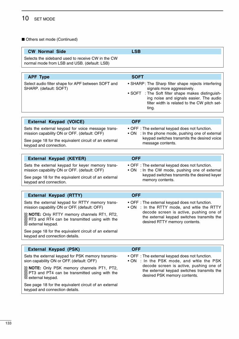
Others set mode (Contnued)
CW Normal Side LSB
Selects the sdeband used to receve CW n the CW normal mode from LSB and USB. (default: LSB)
APF Type SOFTSelect audo filter shape for APF between SOFT and SHARP. (default: SOFT)
• SHARP : The Sharp filter shape rejects nterferng sgnals more aggressvely.
• SOFT : The Soft filter shape makes dstngush-ng nose and sgnals easer. The audo filter wdth s related to the CW ptch set-tng.
External Keypad (VOICE) OFF
Sets the external keypad for voce message trans-msson capablty ON or OFF. (default: OFF)
See page 18 for the equvalent crcut of an external keypad and connecton.
• OFF : The external keypad does not functon.• ON : In the phone mode, pushng one of external
keypad swtches transmts the desred voce message contents.
External Keypad (KEYER) OFF
Sets the external keypad for keyer memory trans-msson capablty ON or OFF. (default: OFF)
See page 18 for the equvalent crcut of an external keypad and connecton.
• OFF : The external keypad does not functon.• ON : In the CW mode, pushng one of external
keypad swtches transmts the desred keyer memory contents.
External Keypad (RTTY) OFF
Sets the external keypad for RTTY memory trans-msson capablty ON or OFF. (default: OFF)
NOTE: Only RTTY memory channels RT1, RT2, RT3 and RT4 can be transmtted usng wth the external keypad.
See page 18 for the equvalent crcut of an external keypad and connecton detals.
• OFF : The external keypad does not functon.• ON : In the RTTY mode, and whle the RTTY
decode screen s actve, pushng one of the external keypad swtches transmts the desred RTTY memory contents.
External Keypad (PSK) OFF
Sets the external keypad for PSK memory transms-son capablty ON or OFF. (default: OFF)
NOTE: Only PSK memory channels PT1, PT2, PT3 and PT4 can be transmtted usng wth the external keypad.
See page 18 for the equvalent crcut of an external keypad and connecton detals.
• OFF : The external keypad does not functon.• ON : In the PSK mode, and whle the PSK
decode screen s actve, pushng one of the external keypad swtches transmts the desred PSK memory contents.
133
10 SET MODE

Keyboard [F1]–[F4] (VOICE) OFF
Sets the voce message transmsson capablty ON or OFF when one of the [F1] to [F4] keys of the key-board that s connected to the [USB] (A) connector on the front panel s pushed. (default: OFF)
• OFF : [F1] to [F4] keys do not functon.• ON : Pushng one of the [F1] to [F4] keys trans-
mts the desred voce message contents durng a phone mode operaton.
Keyboard [F1]–[F4] (KEYER) OFF
Sets the keyer memory transmsson capablty ON or OFF when one of the [F1] to [F4] key of the key-board that s connected to the [USB] (A) connector on the front panel s pushed. (default: OFF)
• OFF : [F1] to [F4] keys do not functon.• ON : Pushng one of the [F1] to [F4] keys trans-
mts the desred keyer memory contents durng the CW mode operaton.
And whle pushng the [SHIFT] key, push [F1] to [F4] key to repeatedly transmt the desred keyer memory contents.
CI–V Baud Rate Auto
Sets the CI-V data transfer between 300, 1200, 4800, 9600, 19200 bps and “Auto.”(default: Auto)
When “Auto” s selected, the baud rate s automat-cally set, accordng to the data rate of the connected controller.
CI–V Address 7Ah
To dstngush equpment, each CI-V transcever has ts own Icom standard address n hexadecmal code. The IC-7600’s address s 7Ah.
When 2 or more IC-7600’s are connected to an optonal CT-17 ci-v level converter, rotate the man dal to select a dfferent address for each IC-7600; the range s 01h to 7Fh.
CI–V Transceive ON
Transceve operaton s possble wth the IC-7600 connected to other Icom HF transcevers or recevers.(default: ON)
• OFF : Transceve operaton OFF• ON : Transceve operaton ON Changng the frequency, operatng mode,
etc. on the IC-7600 automatcally changes those of other connected transcevers (or recevers) and vce versa.
USB Serial Function CI-V
Selects the [USB] connector output data format between CI-V and Decode. (default: CI-V)
• CI-V : Outputs data n CI-V format.• Decode : Outputs decoded contents n ASCII code
format.
Contnued on the next page.
134
10SET MODE
1
2
3
4
5
6
7
8
9
10
11
12
13
14
15
16
17
18
19
20
21
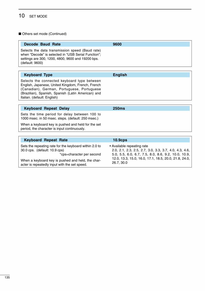
Others set mode (Contnued)
Decode Baud Rate 9600
Selects the data transmsson speed (Baud rate) when “Decode” s selected n “USB Seral Functon”; settngs are 300, 1200, 4800, 9600 and 19200 bps. (default: 9600)
Keyboard Type English
Selects the connected keyboard type between Englsh, Japanese, Unted Kngdom, French, French (Canadan), German, Portuguese, Portuguese (Brazlan), Spansh, Spansh (Latn Amercan) and Italan. (default: Englsh)
Keyboard Repeat Delay 250ms
Sets the tme perod for delay between 100 to 1000 msec. n 50 msec. steps. (default: 250 msec.)
When a keyboard key s pushed and held for the set perod, the character s nput contnuously.
Keyboard Repeat Rate 10.9cps
Sets the repeatng rate for the keyboard wthn 2.0 to 30.0 cps. (default: 10.9 cps)
*cps=character per second
When a keyboard key s pushed and held, the char-acter s repeatedly nput wth the set speed.
• Avalable repeatng rate 2.0, 2.1, 2.3, 2.5, 2.7, 3.0, 3.3, 3.7, 4.0, 4.3, 4.6,
5.0, 5.5, 6.0, 6.7, 7.5, 8.0, 8.6, 9.2, 10.0, 10.9, 12.0, 13.3, 15.0, 16.0, 17.1, 18.5, 20.0, 21.8, 24.0, 26.7, 30.0
135
10 SET MODE
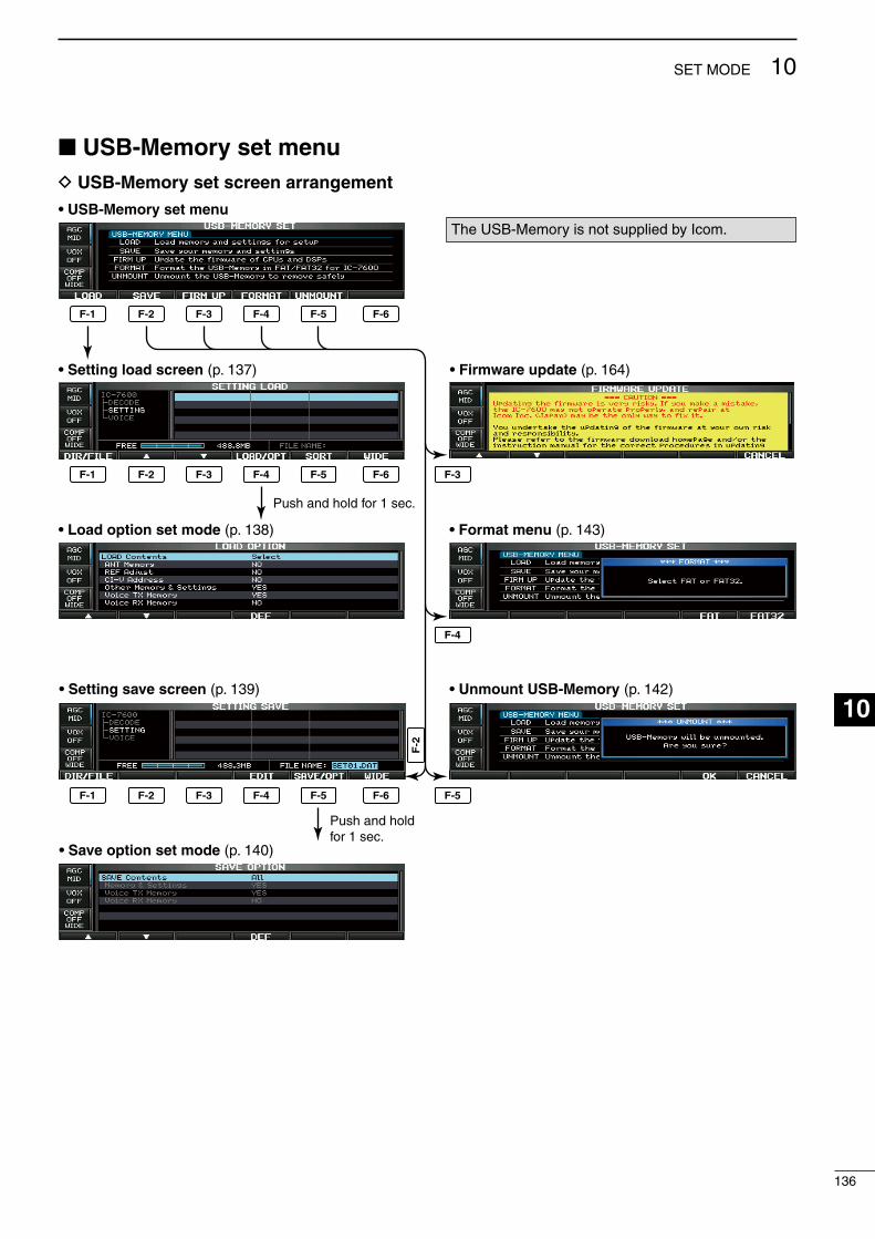
USB-Memory set menuD USB-Memory set screen arrangement
F-1 F-2 F-3 F-4 F-5 F-6
F-1 F-2 F-3 F-4 F-5 F-6
• USB-Memory set menu
• Setting load screen (p. 137)
• Load option set mode (p. 138)
• Firmware update (p. 164)
• Format menu (p. 143)
• Setting save screen (p. 139)
• Save option set mode (p. 140)
F-1 F-2 F-3 F-4
F-3
F-4
F-2
F-5 F-6
• Unmount USB-Memory (p. 142)
F-5
Push and hold for 1 sec.
Push and holdfor 1 sec.
The USB-Memory s not suppled by Icom.
136
10SET MODE
1
2
3
4
5
6
7
8
9
10
11
12
13
14
15
16
17
18
19
20
21

137
10 SET MODE
File loading
F-1 F-2 F-3 F-5
F-4 F-6
EXIT/SET Main dial
USBLOAD/OPT
LOAD OK
By loadng the saved settng fle from the USB-Memory, you can easly set up another IC-7600 or apply the several operators settngs to one IC-7600.
q Durng the set mode menu screen dsplay, push [USB] (F-6) to select the USB set menu screen.
w Push [LOAD] (F-1) to select settng load screen.e Push and hold [LOAD/OPT] (F-4) for 1 sec. to
select the load opton set mode, then rotate the man dal to set the desred loadng condtons, f desred.
• See page 138 for detals.r Push [EXIT/SET] to set.t Push [Y] (F-2) or [Z] (F-3) to select the desred
settng fle.y Push [LOAD/OPT] (F-4). • Confrmaton screen appears.u Push [OK] (F-5) to starts loadng. • After the loadng s completed, the message dalog,
“Reboot the IC-7600,” appears.i Turn the transcever power OFF then ON to make
the settng effectve.

D Load option set mode
LOAD Contents Select
Selects file load condton from All and Select.(default: Select)
• All : Loads and sets the all followng contents. • Select : Loads and sets the selected contents only.
ANT Memory NO
Selects the antenna memory settng loadng cond-ton from YES or NO. (default: NO)
• YES : Loads and sets the antenna memory.• NO : Use the orgnal antenna memory settng.
REF Adjust NOSelects the reference sgnal settng load condton from YES or NO. (default: NO)
• YES : Loads and sets the reference sgnal settng.• NO : Use the orgnal reference sgnal settng.
CI–V Address NO
Selects the CI-V address settng load condton from YES or NO. (default: NO).
• YES : Loads and sets the CI-V address settng.• NO : Use the orgnal CI-V address settng.
Other Memory & Settings YES
Ths settng s fixed “YES.” • YES : Loads and sets the memory channel con-tents and other settngs.
Voice TX Memory YES
Selects the voce TX message load condton from YES or NO. (default: YES)
• YES : Loads and sets the voce TX message.• NO : Use the orgnal voce TX message.
Voice RX Memory NO
Selects the voce RX message load condton from YES or NO. (default: NO)
• YES : Loads and sets the voce RX message.• NO : Use the orgnal voce RX message.
138
10SET MODE
1
2
3
4
5
6
7
8
9
10
11
12
13
14
15
16
17
18
19
20
21
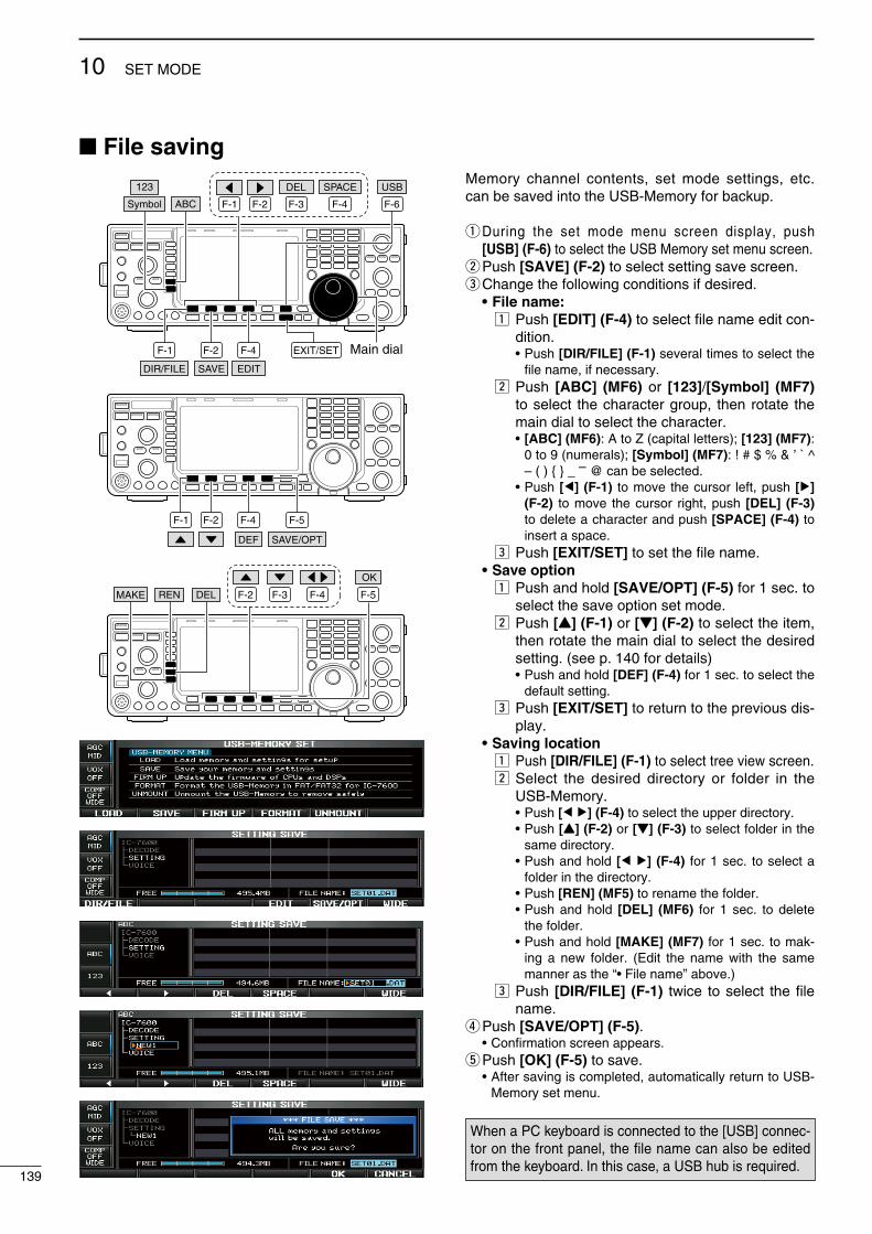
File saving
F-1 F-2 F-4F-3
DEL SPACE
F-1 F-2 F-4
F-6
EXIT/SET Main dial
USB
SAVE EDIT
Symbol ABC
123
DIR/FILE
F-1 F-2 F-4 F-5
DEF SAVE/OPT
F-2 F-4F-3REN DELMAKE F-5
OK
Memory channel contents, set mode settngs, etc. can be saved nto the USB-Memory for backup.
q Durng the set mode menu screen dsplay, push [USB] (F-6) to select the USB Memory set menu screen.
w Push [SAVE] (F-2) to select settng save screen.e Change the followng condtons f desred. • File name: z Push [EDIT] (F-4) to select fle name edt con-
dton. • Push [DIR/FILE] (F-1) several tmes to select the
fle name, f necessary. x Push [ABC] (MF6) or [123]/[Symbol] (MF7)
to select the character group, then rotate the man dal to select the character.
• [ABC] (MF6): A to Z (captal letters); [123] (MF7): 0 to 9 (numerals); [Symbol] (MF7): ! # $ % & ’ ` ^ – ( ) _ – @ can be selected.
• Push [Ω] (F-1) to move the cursor left, push [≈] (F-2) to move the cursor rght, push [DEL] (F-3) to delete a character and push [SPACE] (F-4) to nsert a space.
c Push [EXIT/SET] to set the fle name. • Save option z Push and hold [SAVE/OPT] (F-5) for 1 sec. to
select the save opton set mode. x Push [Y] (F-1) or [Z] (F-2) to select the tem,
then rotate the man dal to select the desred settng. (see p. 140 for detals)
• Push and hold [DEF] (F-4) for 1 sec. to select the default settng.
c Push [EXIT/SET] to return to the prevous ds-play.
• Saving location z Push [DIR/FILE] (F-1) to select tree vew screen. x Select the desred drectory or folder n the
USB-Memory. • Push [Ω ≈] (F-4) to select the upper drectory. • Push [Y] (F-2) or [Z] (F-3) to select folder n the
same drectory. • Push and hold [Ω ≈] (F-4) for 1 sec. to select a
folder n the drectory. • Push [REN] (MF5) to rename the folder. • Push and hold [DEL] (MF6) for 1 sec. to delete
the folder. • Push and hold [MAKE] (MF7) for 1 sec. to mak-
ng a new folder. (Edt the name wth the same manner as the “• Fle name” above.)
c Push [DIR/FILE] (F-1) twce to select the fle name.
r Push [SAVE/OPT] (F-5). • Confrmaton screen appears.t Push [OK] (F-5) to save. • After savng s completed, automatcally return to USB-
Memory set menu.
When a PC keyboard s connected to the [USB] connec-tor on the front panel, the file name can also be edted from the keyboard. In ths case, a USB hub s requred.
139
10 SET MODE
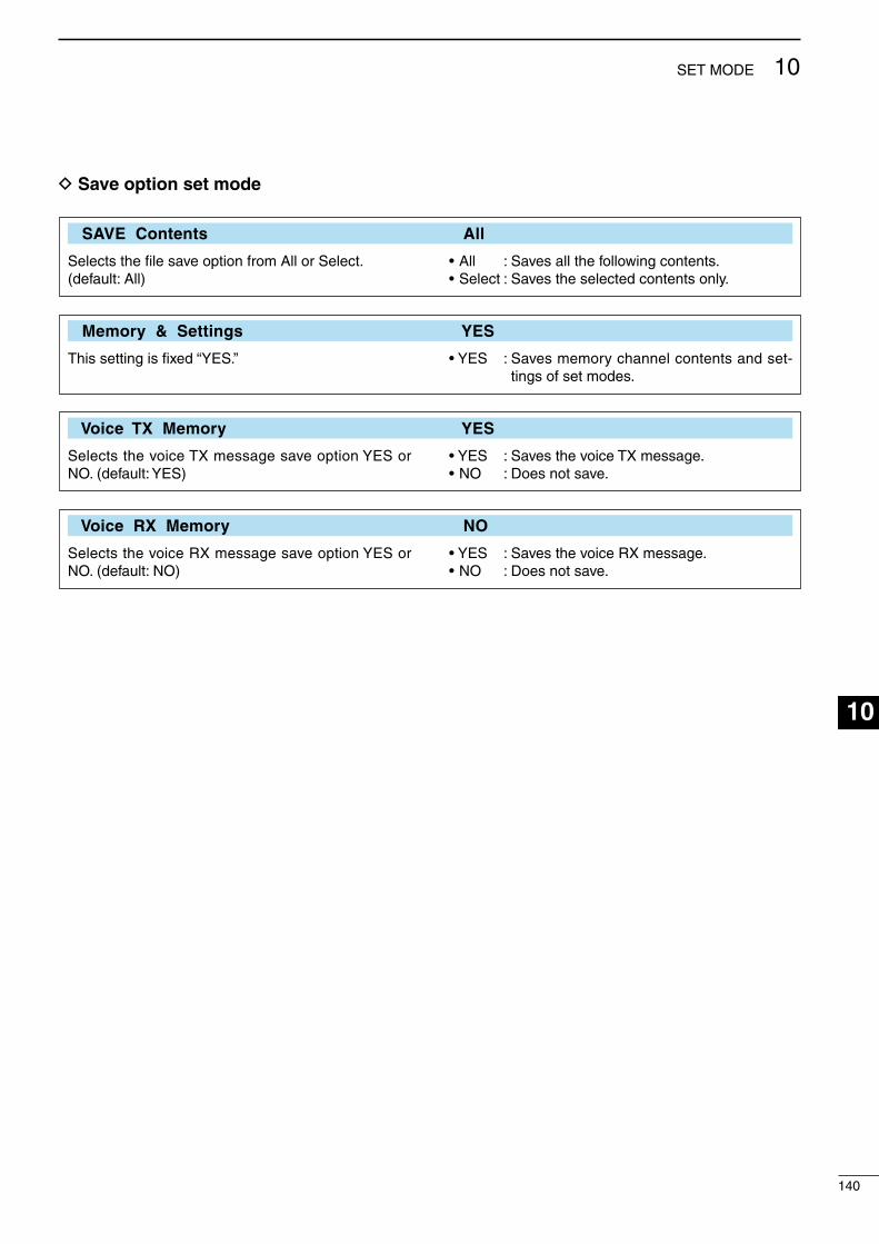
140
10SET MODE
1
2
3
4
5
6
7
8
9
10
11
12
13
14
15
16
17
18
19
20
21
D Save option set mode
SAVE Contents All
Selects the file save opton from All or Select.(default: All)
• All : Saves all the followng contents.• Select : Saves the selected contents only.
Memory & Settings YES
Ths settng s fixed “YES.” • YES : Saves memory channel contents and set-tngs of set modes.
Voice TX Memory YES
Selects the voce TX message save opton YES or NO. (default: YES)
• YES : Saves the voce TX message.• NO : Does not save.
Voice RX Memory NO
Selects the voce RX message save opton YES or NO. (default: NO)
• YES : Saves the voce RX message.• NO : Does not save.
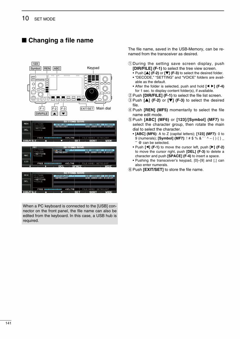
Changing a file name
Keypad
F-1 F-2 F-3 EXIT/SET Main dialDIR/FILE
RENSymbol ABC
123
When a PC keyboard s connected to the [USB] con-nector on the front panel, the file name can also be edted from the keyboard. In ths case, a USB hub s requred.
The fle name, saved n the USB-Memory, can be re-named from the transcever as desred.
q Durng the settng save screen dsplay, push [DIR/FILE] (F-1) to select the tree vew screen.
• Push [Y] (F-2) or [Z] (F-3) to select the desred folder. • “DECODE,” “SETTING” and “VOICE” folders are aval-
able as the default. • After the folder s selected, push and hold [Ω ≈] (F-4)
for 1 sec. to dsplay content folder(s), f avalable.w Push [DIR/FILE] (F-1) to select the fle lst screen.e Push [Y] (F-2) or [Z] (F-3) to select the desred
fle.r Push [REN] (MF5) momentarly to select the fle
name edt mode.t Push [ABC] (MF6) or [123]/[Symbol] (MF7) to
select the character group, then rotate the man dal to select the character.
• [ABC] (MF6): A to Z (captal letters); [123] (MF7): 0 to 9 (numerals); [Symbol] (MF7): ! # $ % & ’ ` ^ – ( ) _ – @ can be selected.
• Push [Ω] (F-1) to move the cursor left, push [≈] (F-2) to move the cursor rght, push [DEL] (F-3) to delete a character and push [SPACE] (F-4) to nsert a space.
• Pushng the transcever’s keypad, [0]–[9] and [.] can also enter numerals.
y Push [EXIT/SET] to store the fle name.
141
10 SET MODE

Deleting a file
F-1 F-2 F-3 F-5
DIR/FILE
DEL
OK
Unmounting USB-Memory
F-5
OK
UNMOUNT
RECOMMENDATION! Deletng the settng fle s rreversble. Confrm the contents before deletng a settng fle!
q Durng the settng save screen dsplay, push [DIR/FILE] (F-1) to select the tree vew screen.
• Push [Y] (F-2) or [Z] (F-3) to select the desred folder. • “DECODE,” “SETTING” and “VOICE” folders are aval-
able as the default. • After the folder s selected, push and hold [Ω ≈] (F-4)
for 1 sec. to dsplay content folder(s), f avalable.w Push [DIR/FILE] (F-1) to select fle lst screen.e Push [Y] (F-2) or [Z] (F-3) to select the desred
fle to be deleted.r Push and hold [DEL] (MF6) for 1 sec. • Confrmaton screen appears.t Push [OK] (F-5) to delete. • After the deletng, return to settng save screen auto-
matcally.
CAUTION: When removng the USB-Memory, unmount operaton s recommended. If you do not unmount the memory, data on the USB-memory may be corrupted.
q Durng the USB Memory set menu screen dsplay, push and hold [UNMOUNT] (F-5) for 1 sec.
• A confrmaton screen appears.w Push [OK] (F-5) to unmount the USB-Memory.e After the ndcator above [USB] (A) connector goes
off, remove the USB-Memory.
142
10SET MODE
1
2
3
4
5
6
7
8
9
10
11
12
13
14
15
16
17
18
19
20
21
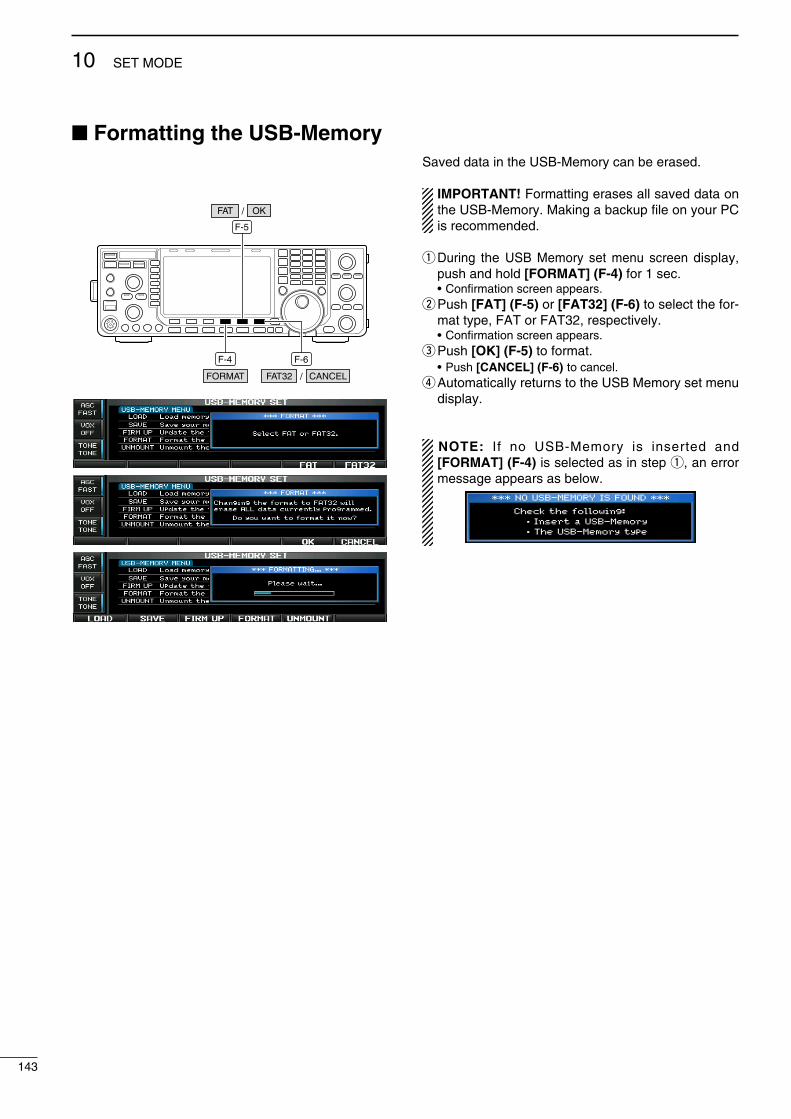
Formatting the USB-Memory
F-6F-4
FORMAT FAT32
F-5
OKFAT /
CANCEL/
Saved data n the USB-Memory can be erased.
IMPORTANT! Formattng erases all saved data on the USB-Memory. Makng a backup fle on your PC s recommended.
q Durng the USB Memory set menu screen dsplay, push and hold [FORMAT] (F-4) for 1 sec.
• Confrmaton screen appears.w Push [FAT] (F-5) or [FAT32] (F-6) to select the for-
mat type, FAT or FAT32, respectvely. • Confrmaton screen appears.e Push [OK] (F-5) to format. • Push [CANCEL] (F-6) to cancel.r Automatcally returns to the USB Memory set menu
dsplay.
NOTE: If no USB-Memory s nserted and [FORMAT] (F-4) s selected as n step q, an error message appears as below.
143
10 SET MODE

D Transceiver powerPROBLEM POSSIBLE CAUSE SOLUTION REF.
Power does not come on when the [POWER] swtch s pushed.
• Power cable s mproperly connected.• Fuse s blown.
• Re-connect the DC power cable correctly.• Check for the cause, then replace the fuse
wth the spare one. ( Fuses are nstalled n the DC power cable
and the nternal PA unt.)
p. 20p. 149
D Transmit and receivePROBLEM POSSIBLE CAUSE SOLUTION REF.
No sounds from the speaker. • Volume level s too low.
• The squelch s closed.
• The transcever s n transmt.
• Rotate the [AF] control clockwse to obtan a sutable lstenng level.
• Rotate the [RF/SQL] control to 11 o’clock poston to open the squelch.
• Push [TRANSMIT] to receve or check the SEND lne of an external unt, f connected.
p. 34
p. 33
p. 36
Senstvty s too low, and only strong sgnals are audble.
• The antenna s not connected properly.• The antenna for another band s selected.
• The antenna s not properly tuned.
• The attenuator s actvated.
• Re-connect to the antenna connector.• Select an antenna sutable for the operatng
frequency.• Push and hold [TUNER] for 1 sec. to manually
tune the antenna.• Push [ATT] (MF4) several tmes to select
“ATT OFF.”
—p. 112
p. 113
p. 72
Receved audo s unclear or dstorted.
• Wrong operatng mode s selected.• PBT functon s actvated.
• Nose blanker s turned ON when recevng a strong sgnal.
• Preamp s actvated.
• The nose reducton s actvated and the [NR] control s too far clockwse.
• Select a sutable operatng mode.• Push and hold [PBT-CLR] for 1 sec. to reset
the functon.• Push [NB] to turn the nose blanker OFF.
• Push [P.AMP] (MF3) once or twce to turn the functon OFF.
• Set the [NR] control for maxmum readablty.
p. 32p. 75
p. 81
p. 72
p. 82
The [ANT] swtch does not functon
• The antenna swtch has not been actvated. • Set the antenna swtch n the set mode to “Auto” or “Manual.”
p. 130
Transmttng s mpossble. • The operatng frequency s not nsde a ham band.
• Set the frequency to be n a ham band. p. 28
Output power s too low. • The [RF POWER] control s set too far coun-terclockwse
• The drve gan level s set too hgh.• The [MIC GAIN] control s set too far counter-
clockwse• The antenna for another band s selected.
• The antenna s not properly tuned.
• Rotate the [RF POWER] control clockwse.
• Set the drve gan level to a sutable level.• Set the [MIC GAIN] control to a sutable pos-
ton.• Select an antenna sutable for the operatng
frequency.• Push and hold [TUNER] for 1 sec. to manually
tune the antenna.
p. 36
p. 37p. 36
p. 112
p. 113
No contact can be made wth another staton.
• RIT or ∂TX functon s actvated.
• Splt frequency functon and/or dualwatch are/s actvated.
• Push [RIT] or [∂TX] to turn the functon OFF.
• Push [SPLIT] and/or [DUALWATCH] to turn the functon OFF.
pgs. 73, 87pgs. 79, 88
Transmt sgnal s unclear or dstorted.
• The [MIC GAIN] control s set too far clock-wse.
• The speech compressor functon s actvated.
• Set the [MIC GAIN] control to a sutable pos-ton.
• Push [COMP] (MF7) to turn the functon OFF.
p. 37
p. 86
Repeater cannot be accessed. • Splt frequency functon s not actvated.• Programmed subaudble tone frequency s
wrong.
• Push [SPLIT] to to turn the functon ON• Reset the frequency usng the set mode.
p. 88p. 28
TroubleshootingThe followng chart s desgned to help you correct problems whch are not equpment malfunctons.
If you are unable to locate the cause of a problem or solve t through the use of ths chart, contact your nearest Icom Dealer or Servce Center.
11
144
MAINTENANCE
1
2
3
4
5
6
7
8
9
10
11
12
13
14
15
16
17
18
19
20
21
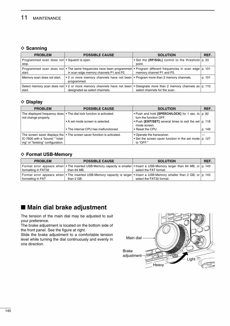
145
11 MAINTENANCE
Main dial brake adjustment The tenson of the man dal may be adjusted to sut your preference.The brake adjustment s located on the bottom sde of the front panel. See the fgure at rght.Slde the brake adjustment to a comfortable tenson level whle turnng the dal contnuously and evenly n one drecton.
Main dial
Brakeadjustment
Light
Heavy
D ScanningPROBLEM POSSIBLE CAUSE SOLUTION REF.
Programmed scan does not stop.
• Squelch s open. • Set the [RF/SQL] control to the threshold pont.
p. 33
Programmed scan does not start.
• The same frequences have been programmed n scan edge memory channels P1 and P2.
• Program dfferent frequences n scan edge memory channel P1 and P2.
p. 101
Memory scan does not start. • 2 or more memory channels have not been programmed.
• Program more than 2 memory channels. p. 101
Select memory scan does not start.
• 2 or more memory channels have not been desgnated as select channels.
• Desgnate more than 2 memory channels as select channels for the scan.
p. 110
D DisplayPROBLEM POSSIBLE CAUSE SOLUTION REF.
The dsplayed frequency does not change properly.
• The dal lock functon s actvated.
• A set mode screen s selected.
• The nternal CPU has malfunctoned.
• Push and hold [SPEECH/LOCK] for 1 sec. to turn the functon OFF.
• Push [EXIT/SET] several tmes to ext the set mode screen.
• Reset the CPU.
p. 82
p. 118
p. 149
The screen saver dsplays the IC-7600 wth a “bound,” “rotat-ng” or “twstng” configuraton.
• The screen saver functon s actvated. • Operate the transcever.• Set the screen saver functon n the set mode
to “OFF.”
—p. 127
D Format USB-MemoryPROBLEM POSSIBLE CAUSE SOLUTION REF.
Format error appears when formattng n FAT32
• The nserted USB-Memory capacty s smaller than 64 MB.
• Insert a USB-Memory larger than 64 MB, or select the FAT format.
p. 143
Format error appears when formattng n FAT
• The nserted USB-Memory capacty s larger than 2 GB.
• Insert a USB-Memory smaller than 2 GB, or select the FAT32 format.
p. 143

SWR readingThe SWR meter dsplays the SWR over the transms-son lne n all modes.
q Push [TUNER] to turn the antenna tuner OFF.w Push and hold [METER] (MF2) for 1 sec. to dsplay
mult-functon meter.e Push [RTTY/PSK] once or twce to select the
RTTY mode.r Push [TRANSMIT].t Rotate [RF POWER] clockwse past the 12 o’clock
poston for more than 30 W output power.y Read the SWR on the SWR meter gage.u Push [EXIT/SET] to close mult-functon meter.
The bult-n antenna tuner matches the transmtter to the antenna when the SWR s lower than 3 : 1.
[RF POWER]
METERTRANSMIT TUNER
RTTY/PSK EXIT/SET
Screen type and font selections2 types of screen mages and 3 types of frequency readout dsplay fonts are avalable n the IC-7600.
q Push [EXIT/SET] several tmes to close mult-func-ton screen, f necessary.
w Push [SET] (F-6) to select the set mode menu screen.
e Push [DISP] (F-3) to select the dsplay set mode.r Push [Y] (F-1) or [Z] (F-2) to select “Dsplay
Type” tem when selectng the screen mage, select “Dsplay Font” when selectng the frequency read-out dsplay font.
t Rotate the man dal to select the desred screen mage or font.
• Screen mage s selectable from A (Black back) and B (Blue back).
• Basc, Italc and Round are avalable for the frequency readout font.
y Push [EXIT/SET] twce to ext from the dsplay set mode.
F-1 F-2 F-3 F-4
F-6
DISP
EXIT/SET Main dial
SET
DEF
• Screen image example— Display Type: B, Display Font: Italic
Better than 1.5:1
146
11MAINTENANCE
1
2
3
4
5
6
7
8
9
10
11
12
13
14
15
16
17
18
19
20
21
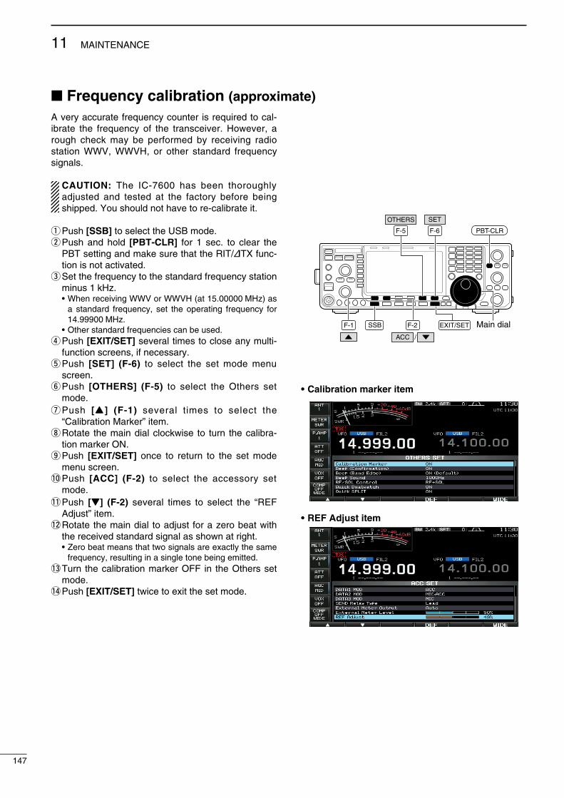
Frequency calibration (approximate)A very accurate frequency counter s requred to cal-brate the frequency of the transcever. However, a rough check may be performed by recevng rado staton WWV, WWVH, or other standard frequency sgnals.
CAUTION: The IC-7600 has been thoroughly adjusted and tested at the factory before beng shpped. You should not have to re-calbrate t.
q Push [SSB] to select the USB mode.w Push and hold [PBT-CLR] for 1 sec. to clear the
PBT settng and make sure that the RIT/∂TX func-ton s not actvated.
e Set the frequency to the standard frequency staton mnus 1 kHz.
• When recevng WWV or WWVH (at 15.00000 MHz) as a standard frequency, set the operatng frequency for 14.99900 MHz.
• Other standard frequences can be used.r Push [EXIT/SET] several tmes to close any mult-
functon screens, f necessary.t Push [SET] (F-6) to select the set mode menu
screen.y Push [OTHERS] (F-5) to select the Others set
mode.u Push [Y ] (F-1) several tmes to select the
“Calbraton Marker” tem.i Rotate the man dal clockwse to turn the calbra-
ton marker ON.o Push [EXIT/SET] once to return to the set mode
menu screen.!0 Push [ACC] (F-2) to select the accessory set
mode.!1 Push [Z] (F-2) several tmes to select the “REF
Adjust” tem.!2 Rotate the man dal to adjust for a zero beat wth
the receved standard sgnal as shown at rght. • Zero beat means that two sgnals are exactly the same
frequency, resultng n a sngle tone beng emtted.!3 Turn the calbraton marker OFF n the Others set
mode.!4 Push [EXIT/SET] twce to ext the set mode.
F-1 F-2
F-6
EXIT/SET Main dial
SET
F-5
OTHERS
ACC
SSB
PBT-CLR
/
• Calibration marker item
• REF Adjust item
147
11 MAINTENANCE

Opening the transceiver’s caseFollow the case openng procedures shown here when you want to replace the clock backup battery or nternal fuse.
CAUTION: Turn the power OFF and dsconnect the DC power cable from the transcever before performng any work on the transcever. Otherwse, there s danger of electrc shock and/or equpment damage.
q Remove the two screws from the carryng handle-and remove the handle from the transcever.
w Remove the 6 screws from the top of the trans-cever and the 4 screws from the sdes, then lft up the top cover.
e Turn the transcever upsde-down.
CAUTION: NEVER HOLD THE MAIN DIAL OR ANY OTHER KNOBS when the transcever s beng turned upsde down. Ths may damage them, or cause you to drop the transcever.
r Remove the 6 screws from the bottom, and then lft off the bottom cover.
About the leg padsTo detach the leg pads from the rght sde panel of the top/bottom cover, push them from the nner sde of each cover after steps q to r as above.
Carrying handle
Top cover
Bottom cover
PA shieldingplate
Clock backup battery replacementThe IC-7600 has a lthum backup battery (CR2032) nsde for clock and tmer functons. The usual lfe of the backup battery s approxmately 2 years.When the backup battery s dscharged, the trans-cever transmts and receves normally but cannot retan the current tme.
CAUTION: Turn the power OFF and dsconnect the DC power cable from the transcever before removng the transcever’s cover.
q Remove the bottom cover as shown above.w Replace the clock backup battery, located on the
front panel as llustrated to the rght. • Make sure the battery polarty s correct.e Return the bottom cover to the orgnal poston.r Set the date and tme n the tme set mode.
(p. 116)
148
11MAINTENANCE
1
2
3
4
5
6
7
8
9
10
11
12
13
14
15
16
17
18
19
20
21
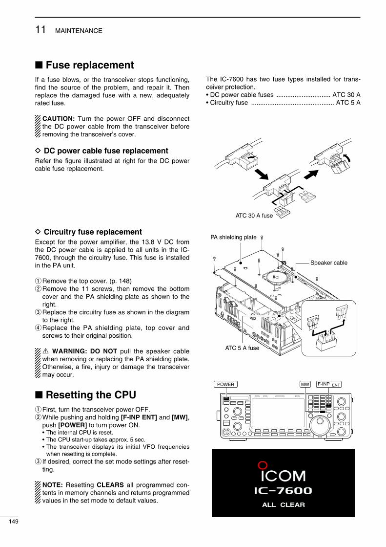
Fuse replacementIf a fuse blows, or the transcever stops functonng, fnd the source of the problem, and repar t. Then replace the damaged fuse wth a new, adequately rated fuse.
CAUTION: Turn the power OFF and dsconnect the DC power cable from the transcever before removng the transcever’s cover.
D DC power cable fuse replacementRefer the fgure llustrated at rght for the DC power cable fuse replacement.
D Circuitry fuse replacementExcept for the power amplfer, the 13.8 V DC from the DC power cable s appled to all unts n the IC-7600, through the crcutry fuse. Ths fuse s nstalled n the PA unt.
q Remove the top cover. (p. 148)w Remove the 11 screws, then remove the bottom
cover and the PA sheldng plate as shown to the rght.
e Replace the crcutry fuse as shown n the dagram to the rght.
r Replace the PA sheldng plate, top cover and screws to ther orgnal poston.
R WARNING: DO NOT pull the speaker cable when removng or replacng the PA sheldng plate. Otherwse, a fre, njury or damage the transcever may occur.
Resetting the CPUq Frst, turn the transcever power OFF.w Whle pushng and holdng [F-INP ENT] and [MW],
push [POWER] to turn power ON. • The nternal CPU s reset. • The CPU start-up takes approx. 5 sec. • The transcever dsplays ts ntal VFO frequences
when resettng s complete.e If desred, correct the set mode settngs after reset-
tng.
NOTE: Resettng CLEARS all programmed con-tents n memory channels and returns programmed values n the set mode to default values.
The IC-7600 has two fuse types nstalled for trans-cever protecton.• DC power cable fuses .............................. ATC 30 A • Crcutry fuse .............................................. ATC 5 A
ATC 30 A fuse
PA shielding plate
ATC 5 A fuse
Speaker cable
POWER F-INP ENT MW
149
11 MAINTENANCE

About protection displaysThe IC-7600 has a 2-step protecton functon to pro-tect the fnal power amplfers.The protector montors the power amplfer temper-ature and actvates when the temperature becomes extremely hgh.
• Reduced power transmission Reduces the transmt output power to 50 W. “LMT” appears besde the TX ndcator (p. 14) dur-
ng transmt.• Transmission inhibit Deactvates the transmtter. The TX ndcator (p. 14) s dsplayed n gray durng
transmt.
When the protector s actvated, wat untl the power amplfer cools down, usng the transcever n only stand-by or receve mode.
NOTE: DO NOT turn the transcever power OFF when the protector s ON. If you do, the coolng fan wll not functon and t wll take longer to cool the transcever.
The power amplfer temperature can be montored n the mult-functon meter, TEMP gauge.
Screen saver functionThe IC-7600 has a screen saver functon to protect the LCD from the “burn-n” effect.
q Push [EXIT/SET] several tmes to close any mult-functon screens.
w Push [SET] (F-6) to select the set mode menu screen.
e Push [DISP] (F-3) to select the dsplay set mode.r Push [Y] (F-1) or [Z] (F-2) several tmes to select
the “Screen Saver Functon” tem.t Rotate the man dal to select the desred tme
perod for the screen saver actvaton from 15, 30, 60 mn. and OFF.
• Deactvate the screen saver wth “OFF” selecton.y Push [Z] (F-2) to select the “Screen Saver Type”
tem.u Rotate the man dal to select the screen saver type
from “Bound,” “Rotaton” and “Twst.” • Push and hold [PREVIEW] (F-5) to dsplay the pattern
for your reference.i Push [EXIT/SET] twce to ext the set mode.
NOTE: When the screen saver functon s act-vated, the LCD unt brghtness s set to dark (0%), and the ndcator on the [NR] swtch blnks.
Check the temperature
F-1 F-2 F-3
F-6
DISP
EXIT/SET Main dial
SET
F-5
PREVIEW
When “Twst” s selected
150
11MAINTENANCE
1
2
3
4
5
6
7
8
9
10
11
12
13
14
15
16
17
18
19
20
21
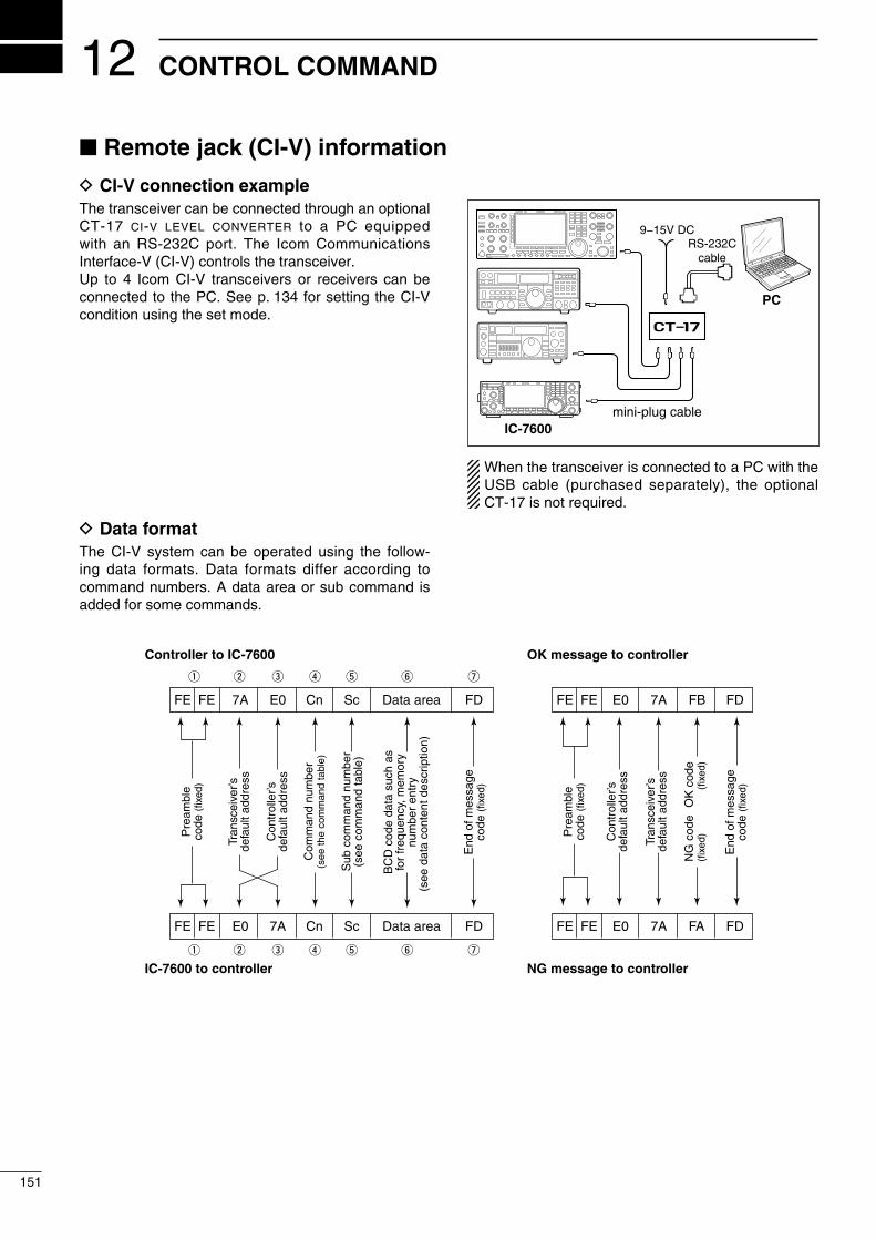
Remote jack (CI-V) information
Controller to IC-7600
FE FE 7A E0 Cn Sc Data area FD
Pre
ambl
eco
de (f
ixed
)
Tran
scei
ver’s
defa
ult a
ddre
ss
Con
trol
ler’s
defa
ult a
ddre
ss
Com
man
d nu
mbe
r(s
ee th
e co
mm
and
tabl
e)
Sub
com
man
d nu
mbe
r(s
ee c
omm
and
tabl
e)
BC
D c
ode
data
suc
h as
for
freq
uenc
y, m
emor
ynu
mbe
r en
try
(see
dat
a co
nten
t des
crip
tion)
End
of m
essa
geco
de (f
ixed
)
OK message to controller
FE FE E0 7A FB FD
FE FE E0 7A FA FD
Pre
ambl
eco
de (f
ixed
)
Con
trol
ler’s
defa
ult a
ddre
ss
Tran
scei
ver’s
defa
ult a
ddre
ss
OK
cod
e(f
ixed
)
End
of m
essa
geco
de (f
ixed
)
NG message to controller
NG
cod
e(f
ixed
)
IC-7600 to controller
q w e r t y u
FE FE E0 7A Cn Sc Data area FD
q w e r t y u
12
151
CONTROL COMMAND
D CI-V connection example The transcever can be connected through an optonal CT-17 ci-v level converter to a PC equpped wth an RS-232C port. The Icom Communcatons Interface-V (CI-V) controls the transcever.Up to 4 Icom CI-V transcevers or recevers can be connected to the PC. See p. 134 for settng the CI-V condton usng the set mode.
D Data formatThe CI-V system can be operated usng the follow-ng data formats. Data formats dffer accordng to command numbers. A data area or sub command s added for some commands.
9−15V DC
PC
ct-17
mini-plug cableIC-7600
RS-232Ccable
When the transcever s connected to a PC wth the USB cable (purchased separately), the optonal CT-17 s not requred.
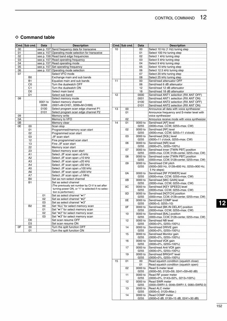
D Command table
Cmd. Sub cmd. Data Description00 see p. 157 Send frequency data for transceve01 see p. 157 Operatng mode selecton for transceve02 see p. 159 Read band edge frequences03 see p. 157 Read operatng frequency04 see p. 157 Read operatng mode05 see p. 157 Set operatng frequency06 see p. 157 Operatng mode selecton07 Select VFO mode
B0 Exchange man and sub bandsB1 Equalze man and sub bandsC0 Turn the dualwatch OFFC1 Turn the dualwatch OND0 Select man bandD1 Select sub band
08 Select memory mode0001 to
0099Select memory channel (0001=M-CH01, 0099=M-CH99)
0100 Select program scan edge channel P10101 Select program scan edge channel P2
09 Memory wrte0A Memory to VFO0B Memory clear0E 00 Scan stop
01 Programmed/memory scan start02 Programmed scan start03 :F scan start12 Fne programmed scan start13 Fne :F scan start22 Memory scan start23 Select memory scan startA1 Select :F scan span ±5 kHzA2 Select :F scan span ±10 kHzA3 Select :F scan span ±20 kHzA4 Select :F scan span ±50 kHzA5 Select :F scan span ±100 kHzA6 Select :F scan span ±500 kHzA7 Select :F scan span ±1 MHzB0 Set as non-select channelB1 Set as select channel
( The prevously set number by CI-V s set after turnng power ON, or “1” s selected f no selec-ton s performed.)
01 Set as select channel “1”02 Set as select channel “2”03 Set as select channel “3”
B2 00 Set “ALL” for select memory scan01 Set “1” for select memory scan02 Set “2” for select memory scan03 Set “3” for select memory scan
D0 Set scan resume OFFD3 Set scan resume ON
0F 00 Turn the splt functon OFF01 Turn the splt functon ON
Cmd. Sub cmd. Data Description10 00 Select 10 Hz (1 Hz) tunng step
01 Select 100 Hz tunng step02 Select 1 kHz tunng step03 Select 5 kHz tunng step04 Select 9 kHz tunng step05 Select 10 kHz tunng step06 Select 12.5 kHz tunng step07 Select 20 kHz tunng step08 Select 25 kHz tunng step
11 00 Send/read attenuator OFF06 Send/read 6 dB attenuator12 Send/read 12 dB attenuator18 Send/read 18 dB attenuator
12 0000 Send/read ANT1 selecton (RX ANT OFF)0001 Send/read ANT1 selecton (RX ANT ON)0100 Send/read ANT2 selecton (RX ANT OFF)0101 Send/read ANT2 selecton (RX ANT ON)
13 00 Announce all data wth voce syntheszer01 Announce frequency and S-meter level wth
voce syntheszer02 Announce receve mode wth voce syntheszer
14 01 0000 to 0255
Send/read [AF] level (0000=max. CCW, 0255=max. CW)
02 0000 to 0255
Send/read [RF] level (0000=max. CCW, 0255=11 o'clock)
03 0000 to 0255
Send/read [SQL] level (0000=11 o'clock, 0255=max. CW)
06 0000 to 0255
Send/read [NR] level (0000=0%, 0255=100%)
07 0000 to 0255
Send/read nner [TWIN PBT] poston (0000=max. CCW, 0128=center, 0255=max. CW)
08 0000 to 0255
Send/read outer [TWIN PBT] poston (0000=max. CCW, 0128=center, 0255=max. CW)
09 0000 to 0255
Send/read CW ptch ( 0000=300 Hz, 0128=600 Hz, 0255=900 Hz; 5 Hz steps)
0A 0000 to 0255
Send/read [RF POWER] level (0000=max. CCW, 0255=max. CW)
0B 0000 to 0255
Send/read [MIC GAIN] level (0000=max. CCW, 0255=max. CW)
0C 0000 to 0255
Send/read [KEY SPEED] level (0000=max. CCW, 0255=max. CW)
0D 0000 to 0255
Send/read [NOTCH] poston (0000=max. CCW, 0128=center, 0255=max. CW)
0E 0000 to 0255
Send/read COMP level(0000=0, 0255=10)
0F 0000 to 0255
Send/read [BK-IN DELAY] poston (0000=max. CCW, 0255=max. CW)
10 0000 to 0255
Send/read [BAL] poston (0000=max. CCW, 0128=center, 0255=max. CW)
12 0000 to 0255
Send/read NB level (0000=0%, 0255=100%)
14 0000 to 0255
Send/read DRIVE gan (0000=0%, 0255=100%)
15 0000 to 0255
Send/read Montor gan (0000=0%, 0255=100%)
16 0000 to 0255
Send/read VOX gan (0000=0%, 0255=100%)
17 0000 to 0255
Send/read Ant VOX gan (0000=0%, 0255=100%)
19 0000 to 0255
Send/read BRIGHT level (0000=0%, 0255=100%)
15 01 00 Read squelch condton (squelch close)01 Read squelch condton (squelch open)
02 0000 to 0255
Read S-meter level (0000=S0, 0120=S9, 0241=S9+60 dB)
11 0000 to 0255
Read RF power meter (0000=0%, 0143=50%, 0213=100%)
12 0000 to 0255
Read SWR meter ( 0000=SWR1.0, 0048=SWR1.5, 0080=SWR2.0)
13 0000 to 0255
Read ALC meter (0000=0, 0120=Max.)
14 0000 to 0255
Read COMP meter (0000=0 dB, 0130=15 dB, 0241=30 dB)
152
12CONTROL COMMAND
1
2
3
4
5
6
7
8
9
10
11
12
13
14
15
16
17
18
19
20
21
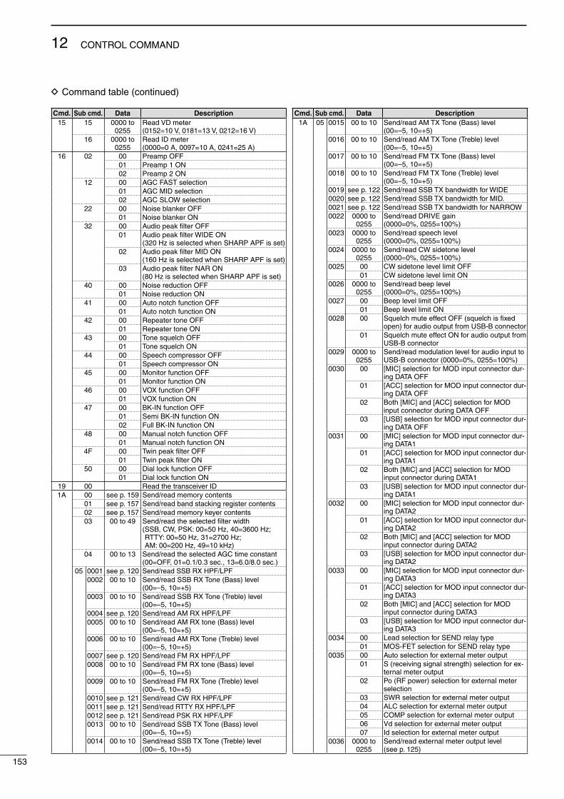
Cmd. Sub cmd. Data Description15 15 0000 to
0255Read VD meter (0152=10 V, 0181=13 V, 0212=16 V)
16 0000 to 0255
Read ID meter (0000=0 A, 0097=10 A, 0241=25 A)
16 02 00 Preamp OFF01 Preamp 1 ON02 Preamp 2 ON
12 00 AGC FAST selecton01 AGC MID selecton02 AGC SLOW selecton
22 00 Nose blanker OFF01 Nose blanker ON
32 00 Audo peak filter OFF01 Audo peak filter WIDE ON
(320 Hz s selected when SHARP APF s set)02 Audo peak filter MID ON
(160 Hz s selected when SHARP APF s set)03 Audo peak filter NAR ON
(80 Hz s selected when SHARP APF s set)40 00 Nose reducton OFF
01 Nose reducton ON41 00 Auto notch functon OFF
01 Auto notch functon ON42 00 Repeater tone OFF
01 Repeater tone ON43 00 Tone squelch OFF
01 Tone squelch ON44 00 Speech compressor OFF
01 Speech compressor ON45 00 Montor functon OFF
01 Montor functon ON46 00 VOX functon OFF
01 VOX functon ON47 00 BK-IN functon OFF
01 Sem BK-IN functon ON02 Full BK-IN functon ON
48 00 Manual notch functon OFF01 Manual notch functon ON
4F 00 Twn peak filter OFF01 Twn peak filter ON
50 00 Dal lock functon OFF01 Dal lock functon ON
19 00 Read the transcever ID1A 00 see p. 159 Send/read memory contents
01 see p. 157 Send/read band stackng regster contents02 see p. 157 Send/read memory keyer contents03 00 to 49 Send/read the selected filter wdth
( SSB, CW, PSK: 00=50 Hz, 40=3600 Hz; RTTY: 00=50 Hz, 31=2700 Hz; AM: 00=200 Hz, 49=10 kHz)
04 00 to 13 Send/read the selected AGC tme constant (00=OFF, 01=0.1/0.3 sec., 13=6.0/8.0 sec.)
05 0001 see p. 120 Send/read SSB RX HPF/LPF0002 00 to 10 Send/read SSB RX Tone (Bass) level
(00=–5, 10=+5)0003 00 to 10 Send/read SSB RX Tone (Treble) level
(00=–5, 10=+5)0004 see p. 120 Send/read AM RX HPF/LPF0005 00 to 10 Send/read AM RX tone (Bass) level
(00=–5, 10=+5)0006 00 to 10 Send/read AM RX Tone (Treble) level
(00=–5, 10=+5)0007 see p. 120 Send/read FM RX HPF/LPF0008 00 to 10 Send/read FM RX tone (Bass) level
(00=–5, 10=+5)0009 00 to 10 Send/read FM RX Tone (Treble) level
(00=–5, 10=+5)0010 see p. 121 Send/read CW RX HPF/LPF0011 see p. 121 Send/read RTTY RX HPF/LPF0012 see p. 121 Send/read PSK RX HPF/LPF0013 00 to 10 Send/read SSB TX Tone (Bass) level
(00=–5, 10=+5)0014 00 to 10 Send/read SSB TX Tone (Treble) level
(00=–5, 10=+5)
Cmd. Sub cmd. Data Description1A 05 0015 00 to 10 Send/read AM TX Tone (Bass) level
(00=–5, 10=+5)0016 00 to 10 Send/read AM TX Tone (Treble) level
(00=–5, 10=+5)0017 00 to 10 Send/read FM TX Tone (Bass) level
(00=–5, 10=+5)0018 00 to 10 Send/read FM TX Tone (Treble) level
(00=–5, 10=+5)0019 see p. 122 Send/read SSB TX bandwdth for WIDE0020 see p. 122 Send/read SSB TX bandwdth for MID.0021 see p. 122 Send/read SSB TX bandwdth for NARROW0022 0000 to
0255Send/read DRIVE gan (0000=0%, 0255=100%)
0023 0000 to 0255
Send/read speech level (0000=0%, 0255=100%)
0024 0000 to 0255
Send/read CW sdetone level (0000=0%, 0255=100%)
0025 00 CW sdetone level lmt OFF01 CW sdetone level lmt ON
0026 0000 to 0255
Send/read beep level(0000=0%, 0255=100%)
0027 00 Beep level lmt OFF01 Beep level lmt ON
0028 00 Squelch mute effect OFF (squelch s fixed open) for audo output from USB-B connector
01 Squelch mute effect ON for audo output from USB-B connector
0029 0000 to 0255
Send/read modulaton level for audo nput to USB-B connector (0000=0%, 0255=100%)
0030 00 [MIC] selecton for MOD nput connector dur-ng DATA OFF
01 [ACC] selecton for MOD nput connector dur-ng DATA OFF
02 Both [MIC] and [ACC] selecton for MOD nput connector durng DATA OFF
03 [USB] selecton for MOD nput connector dur-ng DATA OFF
0031 00 [MIC] selecton for MOD nput connector dur-ng DATA1
01 [ACC] selecton for MOD nput connector dur-ng DATA1
02 Both [MIC] and [ACC] selecton for MOD nput connector durng DATA1
03 [USB] selecton for MOD nput connector dur-ng DATA1
0032 00 [MIC] selecton for MOD nput connector dur-ng DATA2
01 [ACC] selecton for MOD nput connector dur-ng DATA2
02 Both [MIC] and [ACC] selecton for MOD nput connector durng DATA2
03 [USB] selecton for MOD nput connector dur-ng DATA2
0033 00 [MIC] selecton for MOD nput connector dur-ng DATA3
01 [ACC] selecton for MOD nput connector dur-ng DATA3
02 Both [MIC] and [ACC] selecton for MOD nput connector durng DATA3
03 [USB] selecton for MOD nput connector dur-ng DATA3
0034 00 Lead selecton for SEND relay type01 MOS-FET selecton for SEND relay type
0035 00 Auto selecton for external meter output01 S (recevng sgnal strength) selecton for ex-
ternal meter output02 Po (RF power) selecton for external meter
selecton03 SWR selecton for external meter output04 ALC selecton for external meter output05 COMP selecton for external meter output06 Vd selecton for external meter output07 Id selecton for external meter output
0036 0000 to 0255
Send/read external meter output level (see p. 125)
D Command table (contnued)
153
12 CONTROL COMMAND
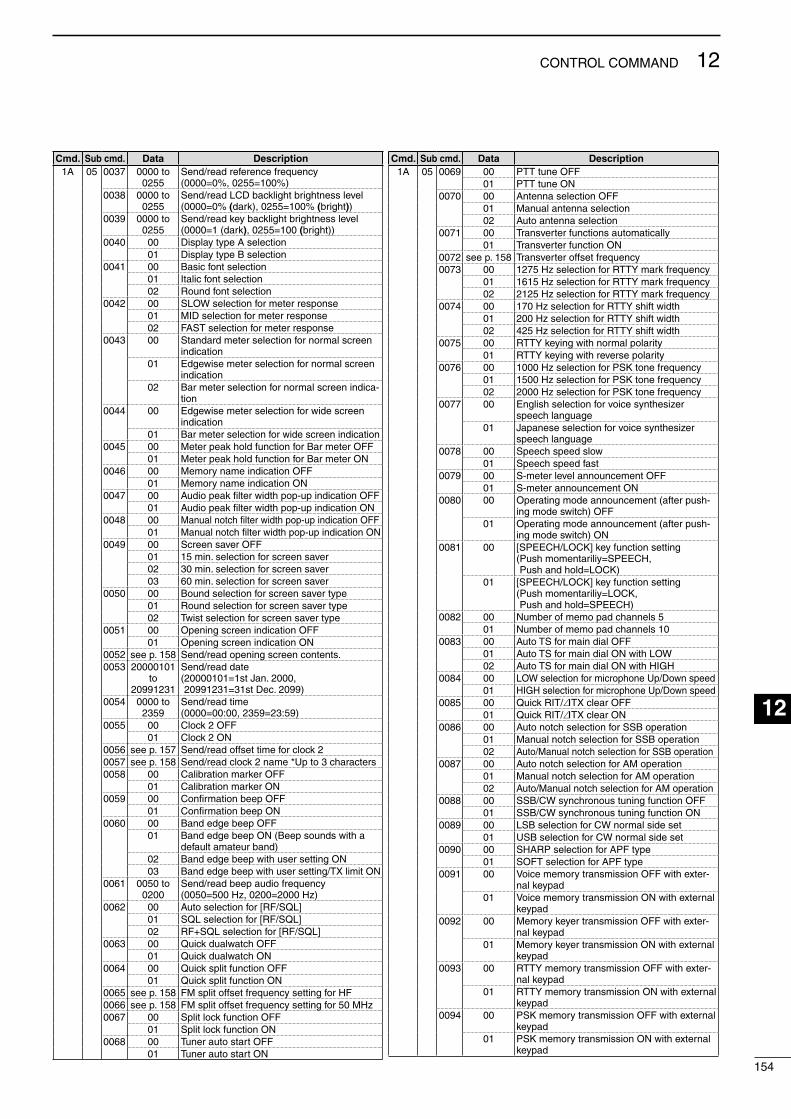
Cmd. Sub cmd. Data Description1A 05 0037 0000 to
0255Send/read reference frequency (0000=0%, 0255=100%)
0038 0000 to 0255
Send/read LCD backlght brghtness level (0000=0% (dark), 0255=100% (brght))
0039 0000 to 0255
Send/read key backlght brghtness level (0000=1 (dark), 0255=100 (brght))
0040 00 Dsplay type A selecton01 Dsplay type B selecton
0041 00 Basc font selecton01 Italc font selecton02 Round font selecton
0042 00 SLOW selecton for meter response01 MID selecton for meter response02 FAST selecton for meter response
0043 00 Standard meter selecton for normal screen ndcaton
01 Edgewse meter selecton for normal screen ndcaton
02 Bar meter selecton for normal screen ndca-ton
0044 00 Edgewse meter selecton for wde screen ndcaton
01 Bar meter selecton for wde screen ndcaton0045 00 Meter peak hold functon for Bar meter OFF
01 Meter peak hold functon for Bar meter ON0046 00 Memory name ndcaton OFF
01 Memory name ndcaton ON0047 00 Audo peak filter wdth pop-up ndcaton OFF
01 Audo peak filter wdth pop-up ndcaton ON0048 00 Manual notch filter wdth pop-up ndcaton OFF
01 Manual notch filter wdth pop-up ndcaton ON0049 00 Screen saver OFF
01 15 mn. selecton for screen saver02 30 mn. selecton for screen saver03 60 mn. selecton for screen saver
0050 00 Bound selecton for screen saver type01 Round selecton for screen saver type02 Twst selecton for screen saver type
0051 00 Openng screen ndcaton OFF01 Openng screen ndcaton ON
0052 see p. 158 Send/read openng screen contents.0053 20000101
to 20991231
Send/read date ( 20000101=1st Jan. 2000, 20991231=31st Dec. 2099)
0054 0000 to 2359
Send/read tme (0000=00:00, 2359=23:59)
0055 00 Clock 2 OFF01 Clock 2 ON
0056 see p. 157 Send/read offset tme for clock 20057 see p. 158 Send/read clock 2 name *Up to 3 characters0058 00 Calbraton marker OFF
01 Calbraton marker ON0059 00 Confirmaton beep OFF
01 Confirmaton beep ON0060 00 Band edge beep OFF
01 Band edge beep ON (Beep sounds wth a default amateur band)
02 Band edge beep wth user settng ON03 Band edge beep wth user settng/TX lmt ON
0061 0050 to 0200
Send/read beep audo frequency (0050=500 Hz, 0200=2000 Hz)
0062 00 Auto selecton for [RF/SQL]01 SQL selecton for [RF/SQL]02 RF+SQL selecton for [RF/SQL]
0063 00 Quck dualwatch OFF01 Quck dualwatch ON
0064 00 Quck splt functon OFF01 Quck splt functon ON
0065 see p. 158 FM splt offset frequency settng for HF0066 see p. 158 FM splt offset frequency settng for 50 MHz0067 00 Splt lock functon OFF
01 Splt lock functon ON0068 00 Tuner auto start OFF
01 Tuner auto start ON
Cmd. Sub cmd. Data Description1A 05 0069 00 PTT tune OFF
01 PTT tune ON0070 00 Antenna selecton OFF
01 Manual antenna selecton02 Auto antenna selecton
0071 00 Transverter functons automatcally01 Transverter functon ON
0072 see p. 158 Transverter offset frequency0073 00 1275 Hz selecton for RTTY mark frequency
01 1615 Hz selecton for RTTY mark frequency02 2125 Hz selecton for RTTY mark frequency
0074 00 170 Hz selecton for RTTY shft wdth01 200 Hz selecton for RTTY shft wdth02 425 Hz selecton for RTTY shft wdth
0075 00 RTTY keyng wth normal polarty01 RTTY keyng wth reverse polarty
0076 00 1000 Hz selecton for PSK tone frequency01 1500 Hz selecton for PSK tone frequency02 2000 Hz selecton for PSK tone frequency
0077 00 Englsh selecton for voce syntheszer speech language
01 Japanese selecton for voce syntheszer speech language
0078 00 Speech speed slow01 Speech speed fast
0079 00 S-meter level announcement OFF01 S-meter announcement ON
0080 00 Operatng mode announcement (after push-ng mode swtch) OFF
01 Operatng mode announcement (after push-ng mode swtch) ON
0081 00 [SPEECH/LOCK] key functon settng ( Push momentarly=SPEECH, Push and hold=LOCK)
01 [SPEECH/LOCK] key functon settng ( Push momentarly=LOCK, Push and hold=SPEECH)
0082 00 Number of memo pad channels 501 Number of memo pad channels 10
0083 00 Auto TS for man dal OFF01 Auto TS for man dal ON wth LOW02 Auto TS for man dal ON wth HIGH
0084 00 LOW selecton for mcrophone Up/Down speed01 HIGH selecton for mcrophone Up/Down speed
0085 00 Quck RIT/:TX clear OFF01 Quck RIT/:TX clear ON
0086 00 Auto notch selecton for SSB operaton01 Manual notch selecton for SSB operaton02 Auto/Manual notch selecton for SSB operaton
0087 00 Auto notch selecton for AM operaton01 Manual notch selecton for AM operaton02 Auto/Manual notch selecton for AM operaton
0088 00 SSB/CW synchronous tunng functon OFF01 SSB/CW synchronous tunng functon ON
0089 00 LSB selecton for CW normal sde set01 USB selecton for CW normal sde set
0090 00 SHARP selecton for APF type01 SOFT selecton for APF type
0091 00 Voce memory transmsson OFF wth exter-nal keypad
01 Voce memory transmsson ON wth external keypad
0092 00 Memory keyer transmsson OFF wth exter-nal keypad
01 Memory keyer transmsson ON wth external keypad
0093 00 RTTY memory transmsson OFF wth exter-nal keypad
01 RTTY memory transmsson ON wth external keypad
0094 00 PSK memory transmsson OFF wth external keypad
01 PSK memory transmsson ON wth external keypad
154
12CONTROL COMMAND
1
2
3
4
5
6
7
8
9
10
11
12
13
14
15
16
17
18
19
20
21
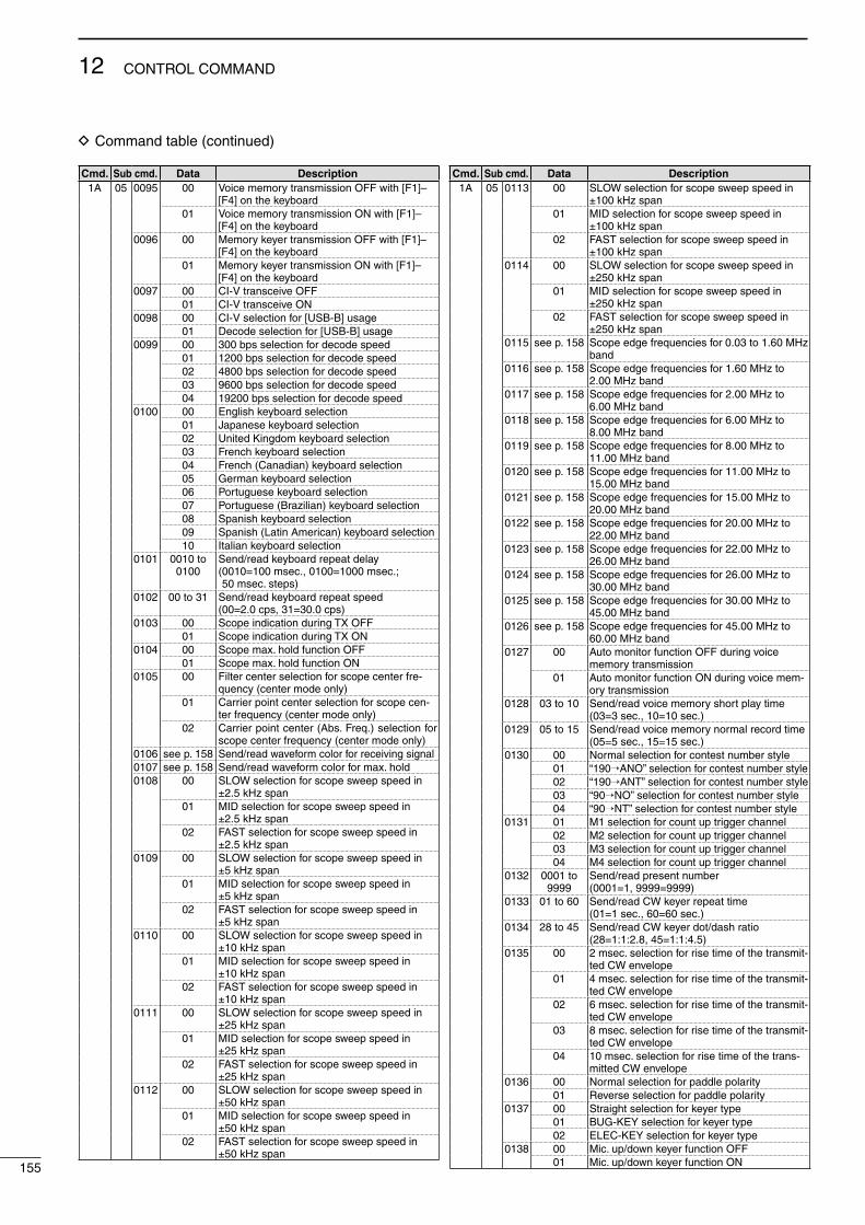
D Command table (contnued)
Cmd. Sub cmd. Data Description1A 05 0095 00 Voce memory transmsson OFF wth [F1]–
[F4] on the keyboard01 Voce memory transmsson ON wth [F1]–
[F4] on the keyboard0096 00 Memory keyer transmsson OFF wth [F1]–
[F4] on the keyboard01 Memory keyer transmsson ON wth [F1]–
[F4] on the keyboard0097 00 CI-V transceve OFF
01 CI-V transceve ON0098 00 CI-V selecton for [USB-B] usage
01 Decode selecton for [USB-B] usage0099 00 300 bps selecton for decode speed
01 1200 bps selecton for decode speed02 4800 bps selecton for decode speed03 9600 bps selecton for decode speed04 19200 bps selecton for decode speed
0100 00 Englsh keyboard selecton01 Japanese keyboard selecton02 Unted Kngdom keyboard selecton03 French keyboard selecton04 French (Canadan) keyboard selecton05 German keyboard selecton06 Portuguese keyboard selecton07 Portuguese (Brazlan) keyboard selecton08 Spansh keyboard selecton09 Spansh (Latn Amercan) keyboard selecton10 Italan keyboard selecton
0101 0010 to 0100
Send/read keyboard repeat delay ( 0010=100 msec., 0100=1000 msec.; 50 msec. steps)
0102 00 to 31 Send/read keyboard repeat speed (00=2.0 cps, 31=30.0 cps)
0103 00 Scope ndcaton durng TX OFF01 Scope ndcaton durng TX ON
0104 00 Scope max. hold functon OFF01 Scope max. hold functon ON
0105 00 Flter center selecton for scope center fre-quency (center mode only)
01 Carrer pont center selecton for scope cen-ter frequency (center mode only)
02 Carrer pont center (Abs. Freq.) selecton for scope center frequency (center mode only)
0106 see p. 158 Send/read waveform color for recevng sgnal0107 see p. 158 Send/read waveform color for max. hold0108 00 SLOW selecton for scope sweep speed n
±2.5 kHz span01 MID selecton for scope sweep speed n
±2.5 kHz span02 FAST selecton for scope sweep speed n
±2.5 kHz span0109 00 SLOW selecton for scope sweep speed n
±5 kHz span01 MID selecton for scope sweep speed n
±5 kHz span02 FAST selecton for scope sweep speed n
±5 kHz span0110 00 SLOW selecton for scope sweep speed n
±10 kHz span01 MID selecton for scope sweep speed n
±10 kHz span02 FAST selecton for scope sweep speed n
±10 kHz span0111 00 SLOW selecton for scope sweep speed n
±25 kHz span01 MID selecton for scope sweep speed n
±25 kHz span02 FAST selecton for scope sweep speed n
±25 kHz span0112 00 SLOW selecton for scope sweep speed n
±50 kHz span01 MID selecton for scope sweep speed n
±50 kHz span02 FAST selecton for scope sweep speed n
±50 kHz span
Cmd. Sub cmd. Data Description1A 05 0113 00 SLOW selecton for scope sweep speed n
±100 kHz span01 MID selecton for scope sweep speed n
±100 kHz span02 FAST selecton for scope sweep speed n
±100 kHz span0114 00 SLOW selecton for scope sweep speed n
±250 kHz span01 MID selecton for scope sweep speed n
±250 kHz span02 FAST selecton for scope sweep speed n
±250 kHz span0115 see p. 158 Scope edge frequences for 0.03 to 1.60 MHz
band0116 see p. 158 Scope edge frequences for 1.60 MHz to
2.00 MHz band0117 see p. 158 Scope edge frequences for 2.00 MHz to
6.00 MHz band0118 see p. 158 Scope edge frequences for 6.00 MHz to
8.00 MHz band0119 see p. 158 Scope edge frequences for 8.00 MHz to
11.00 MHz band0120 see p. 158 Scope edge frequences for 11.00 MHz to
15.00 MHz band0121 see p. 158 Scope edge frequences for 15.00 MHz to
20.00 MHz band0122 see p. 158 Scope edge frequences for 20.00 MHz to
22.00 MHz band0123 see p. 158 Scope edge frequences for 22.00 MHz to
26.00 MHz band0124 see p. 158 Scope edge frequences for 26.00 MHz to
30.00 MHz band0125 see p. 158 Scope edge frequences for 30.00 MHz to
45.00 MHz band0126 see p. 158 Scope edge frequences for 45.00 MHz to
60.00 MHz band0127 00 Auto montor functon OFF durng voce
memory transmsson01 Auto montor functon ON durng voce mem-
ory transmsson0128 03 to 10 Send/read voce memory short play tme
(03=3 sec., 10=10 sec.)0129 05 to 15 Send/read voce memory normal record tme
(05=5 sec., 15=15 sec.)0130 00 Normal selecton for contest number style
01 “190→ANO” selecton for contest number style02 “190→ANT” selecton for contest number style03 “90→NO” selecton for contest number style04 “90→NT” selecton for contest number style
0131 01 M1 selecton for count up trgger channel02 M2 selecton for count up trgger channel03 M3 selecton for count up trgger channel04 M4 selecton for count up trgger channel
0132 0001 to 9999
Send/read present number (0001=1, 9999=9999)
0133 01 to 60 Send/read CW keyer repeat tme (01=1 sec., 60=60 sec.)
0134 28 to 45 Send/read CW keyer dot/dash rato (28=1:1:2.8, 45=1:1:4.5)
0135 00 2 msec. selecton for rse tme of the transmt-ted CW envelope
01 4 msec. selecton for rse tme of the transmt-ted CW envelope
02 6 msec. selecton for rse tme of the transmt-ted CW envelope
03 8 msec. selecton for rse tme of the transmt-ted CW envelope
04 10 msec. selecton for rse tme of the trans-mtted CW envelope
0136 00 Normal selecton for paddle polarty01 Reverse selecton for paddle polarty
0137 00 Straght selecton for keyer type01 BUG-KEY selecton for keyer type02 ELEC-KEY selecton for keyer type
0138 00 Mc. up/down keyer functon OFF01 Mc. up/down keyer functon ON155
12 CONTROL COMMAND
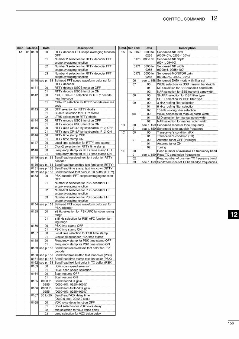
Cmd. Sub cmd. Data Description1A 05 0139 00 RTTY decoder FFT scope averagng functon
OFF01 Number 2 selecton for RTTY decoder FFT
scope averagng functon02 Number 3 selecton for RTTY decoder FFT
scope averagng functon03 Number 4 selecton for RTTY decoder FFT
scope averagng functon0140 see p. 158 Set/read FFT scope waveform color set for
RTTY decoder0141 00 RTTY decode USOS functon OFF
01 RTTY decode USOS functon ON0142 00 “CR,LF,CR+LF” selecton for RTTY decode
new lne code01 “CR+LF” selecton for RTTY decode new lne
code0143 00 OFF selecton for RTTY dddle
01 BLANK selecton for RTTY dddle02 LTRS selecton for RTTY dddle
0144 00 RTTY encode USOS functon OFF01 RTTY encode USOS functon ON
0145 00 RTTY auto CR+LF by keyboard’s [F12] OFF01 RTTY auto CR+LF by keyboard’s [F12] ON
0146 00 RTTY tme stamp OFF01 RTTY tme stamp ON
0147 00 Local tme selecton for RTTY tme stamp01 Clock2 selecton for RTTY tme stamp
0148 00 Frequency stamp for RTTY tme stamp OFF01 Frequency stamp for RTTY tme stamp ON
0149 see p. 158 Send/read receved text font color for RTTY decoder
0150 see p. 158 Send/read transmtted text font color (RTTY)0151 see p. 158 Send/read tme stamp text font color (RTTY)0152 see p. 158 Send/read text font color n TX buffer (RTTY)0153 00 PSK decoder FFT scope averagng functon
OFF01 Number 2 selecton for PSK decoder FFT
scope averagng functon02 Number 3 selecton for PSK decoder FFT
scope averagng functon03 Number 4 selecton for PSK decoder FFT
scope averagng functon0154 see p. 158 Set/read FFT scope waveform color set for
PSK decoder0155 00 ±8 Hz selecton for PSK AFC functon tunng
range01 ±15 Hz selecton for PSK AFC functon tun-
ng range0156 00 PSK tme stamp OFF
01 PSK tme stamp ON0157 00 Local tme selecton for PSK tme stamp
01 Clock2 selecton for PSK tme stamp0158 00 Frequency stamp for PSK tme stamp OFF
01 Frequency stamp for PSK tme stamp ON0159 see p. 158 Send/read receved text font color for PSK
decoder0160 see p. 158 Send/read transmtted text font color (PSK)0161 see p. 158 Send/read tme stamp text font color (PSK)0162 see p. 158 Send/read text font color n TX buffer (PSK)0163 00 LOW scan speed selecton
01 HIGH scan speed selecton0164 00 Scan resume OFF
01 Scan resume ON0165 0000 to
0255Send/read VOX gan (0000=0%, 0255=100%)
0166 0000 to 0255
Send/read ANTI-VOX gan (0000=0%, 0255=100%)
0167 00 to 20 Send/read VOX delay tme (00=0.0 sec., 20=2.0 sec.)
0168 00 VOX voce delay functon OFF01 Short selecton for VOX voce delay02 Md selecton for VOX voce delay03 Long selecton for VOX voce delay
Cmd. Sub cmd. Data Description1A 05 0169 0000 to
0255Send/read NB level (0000=0%, 0255=100%)
0170 00 to 09 Send/read NB depth (00=1, 09=10)
0171 0000 to 0255
Send/read NB wdth (0000=1, 0255=100)
0172 0000 to 0255
Send/read MONITOR gan (0000=0%, 0255=100%)
06 see p. 158 Send/read DATA mode wth filter set07 00 WIDE selecton for SSB transmt bandwdth
01 MID selecton for SSB transmt bandwdth02 NAR selecton for SSB transmt bandwdth
08 00 SHARP selecton for DSP filter type01 SOFT selecton for DSP filter type
09 00 3 kHz roofing filter selecton01 6 kHz roofing filter selecton02 15 kHz roofing filter selecton
0A 00 WIDE selecton for manual notch wdth01 MID selecton for manual notch wdth02 NAR selecton for manual notch wdth
1B 00 see p. 159 Send/read repeater tone frequency01 see p. 159 Send/read tone squelch frequency
1C 00 00 Transcever's condton (RX)01 Transcever's condton (TX)
01 00 Antenna tuner OFF (through)01 Antenna tuner ON02 Tunng
1E 00 Read number of avalable TX frequency band01 see p. 159 Read TX band edge frequences02 Read number of user-set TX frequency band03 see p. 159 Send/read user-set TX band edge frequences
156
12CONTROL COMMAND
1
2
3
4
5
6
7
8
9
10
11
12
13
14
15
16
17
18
19
20
21
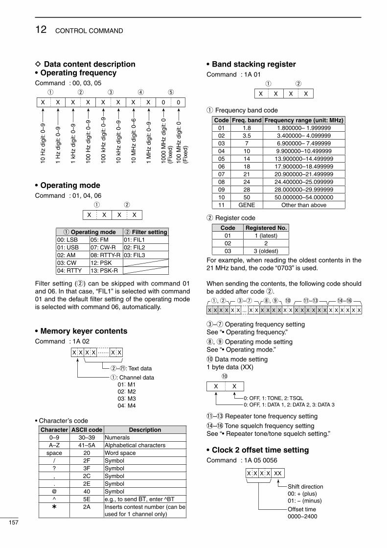
D Data content description• Operating frequencyCommand : 00, 03, 05
q
XX X X X
w e
X
r t
XX 00
10 H
z di
git:
0–9
1 H
z di
git:
0–9
1 kH
z di
git:
0–9
100
Hz
digi
t: 0–
9
100
kHz
digi
t: 0–
9
10 k
Hz
digi
t: 0–
9
10 M
Hz
digi
t: 0–
6
1 M
Hz
digi
t: 0–
9
1000
MH
z di
git:
0 (F
ixed
)
100
MH
z di
git:
0(F
ixed
)• Operating modeCommand : 01, 04, 06
q
XX X X
w
q Operating mode w Filter setting00: LSB 05: FM 01: FIL101: USB 07: CW-R 02: FIL202: AM 08: RTTY-R 03: FIL303: CW 12: PSK04: RTTY 13: PSK-R
Flter settng (w) can be skpped wth command 01 and 06. In that case, “FIL1” s selected wth command 01 and the default filter settng of the operatng mode s selected wth command 06, automatcally.
• Memory keyer contentsCommand : 1A 02
X
q: Channel data01: M102: M203: M304: M4
w–&1: Text data
X X X …… X X
• Character’s code Character ASCII code Description
0–9 30–39 NumeralsA–Z 41–5A Alphabetcal characters
space 20 Word space / 2F Symbol? 3F Symbol, 2C Symbol. 2E Symbol
@ 40 Symbol^ 5E e.g., to send BT, enter ^BT 2A Inserts contest number (can be
used for 1 channel only)
• Band stacking registerCommand : 1A 01
q
XX X X
w
q Frequency band code
Code Freq. band Frequency range (unit: MHz)01 1.8 1.800000– 1.99999902 3.5 3.400000– 4.09999903 7 6.900000– 7.49999904 10 9.900000–10.49999905 14 13.900000–14.49999906 18 17.900000–18.49999907 21 20.900000–21.49999908 24 24.400000–25.09999909 28 28.000000–29.99999910 50 50.000000–54.00000011 GENE Other than above
w Regster code
Code Registered No.01 1 (latest)02 203 3 (oldest)
For example, when readng the oldest contents n the 21 MHz band, the code “0703” s used.
When sendng the contents, the followng code should be added after code w.
e−u i, o !0 !1−!3 !4−!6
X X ... X X X X X X X X X X X X X X X X X XX XX X X X
q, w
e–u Operatng frequency settngSee “• Operatng frequency.”
i, o Operatng mode settngSee “• Operatng mode.”
!0 Data mode settng1 byte data (XX)
X X
!0
0: OFF, 1: TONE, 2: TSQL0: OFF, 1: DATA 1, 2: DATA 2, 3: DATA 3
!1–!3 Repeater tone frequency settng
!4–!6 Tone squelch frequency settngSee “• Repeater tone/tone squelch settng.”
• Clock 2 offset time settingCommand : 1A 05 0056
X
Shift direction00: + (plus)01: − (minus)
Offset time0000−2400
X X X XX
157
12 CONTROL COMMAND
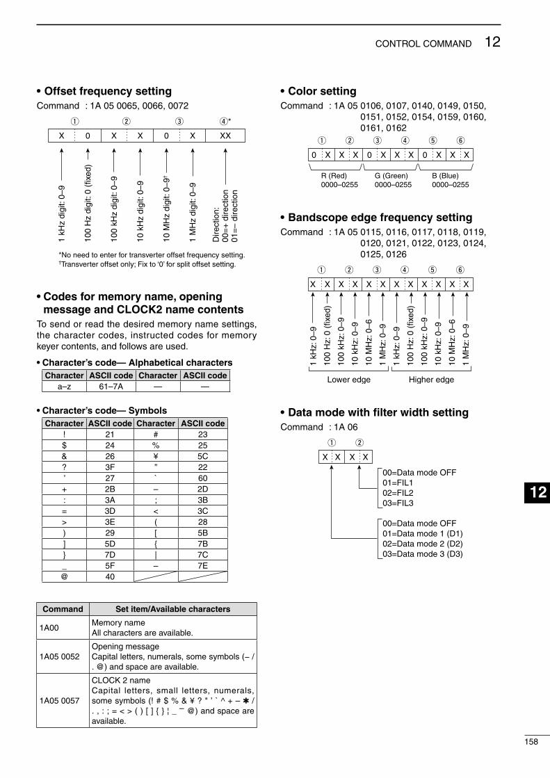
• Offset frequency settingCommand : 1A 05 0065, 0066, 0072
1 kH
z di
git:
0–9
100
Hz
digi
t: 0
(fix
ed)
100
kHz
digi
t: 0–
9
10 k
Hz
digi
t: 0–
9
10 M
Hz
digi
t: 0–
9†
1 M
Hz
digi
t: 0–
9
Dire
ctio
n:
00=
+ d
irect
ion
01=
– di
rect
ion
q
0X X X X XX
w e
0
r*
*No need to enter for transverter offset frequency setting.†Transverter offset only; Fix to ‘0’ for split offset setting.
• Codes for memory name, opening message and CLOCK2 name contents
To send or read the desred memory name settngs, the character codes, nstructed codes for memory keyer contents, and follows are used.
• Character’s code— Alphabetical charactersCharacter ASCII code Character ASCII code
a–z 61–7A — —
• Character’s code— Symbols Character ASCII code Character ASCII code
! 21 # 23$ 24 % 25& 26 ¥ 5C? 3F ” 22’ 27 ` 60+ 2B – 2D: 3A ; 3B= 3D < 3C> 3E ( 28) 29 [ 5B] 5D 7B 7D | 7C_ 5F – 7E@ 40
Command Set item/Available characters
1A00Memory nameAll characters are avalable.
1A05 0052Openng messageCaptal letters, numerals, some symbols (− / . @) and space are avalable.
1A05 0057
CLOCK 2 nameCaptal letters, small letters, numerals, some symbols (! # $ % & ¥ ? " ’ ` ^ + – / . , : ; = < > ( ) [ ] ¦ _ – @) and space are avalable.
• Color setting Command : 1A 05 0106, 0107, 0140, 0149, 0150,
0151, 0152, 0154, 0159, 0160, 0161, 0162
q
0 X X X 0 X X X 0 X X X
w e r t y
R (Red)0000–0255
G (Green)0000–0255
B (Blue)0000–0255
• Bandscope edge frequency settingCommand : 1A 05 0115, 0116, 0117, 0118, 0119,
0120, 0121, 0122, 0123, 0124, 0125, 0126
1 kH
z: 0
–9
100
Hz:
0 (
fixed
)
100
kHz:
0–9
10 k
Hz:
0–9
10 M
Hz:
0–6
1 M
Hz:
0–9
1 kH
z: 0
–9
100
Hz:
0 (
fixed
)
100
kHz:
0–9
10 k
Hz:
0–9
10 M
Hz:
0–6
1 M
Hz:
0–9
q
X X X X X X X X X X X X
w e r t y
Lower edge Higher edge
• Data mode with filter width settingCommand : 1A 06
q
X X X X
w
00=Data mode OFF01=FIL102=FIL203=FIL3
00=Data mode OFF01=Data mode 1 (D1)02=Data mode 2 (D2)03=Data mode 3 (D3)
158
12CONTROL COMMAND
1
2
3
4
5
6
7
8
9
10
11
12
13
14
15
16
17
18
19
20
21
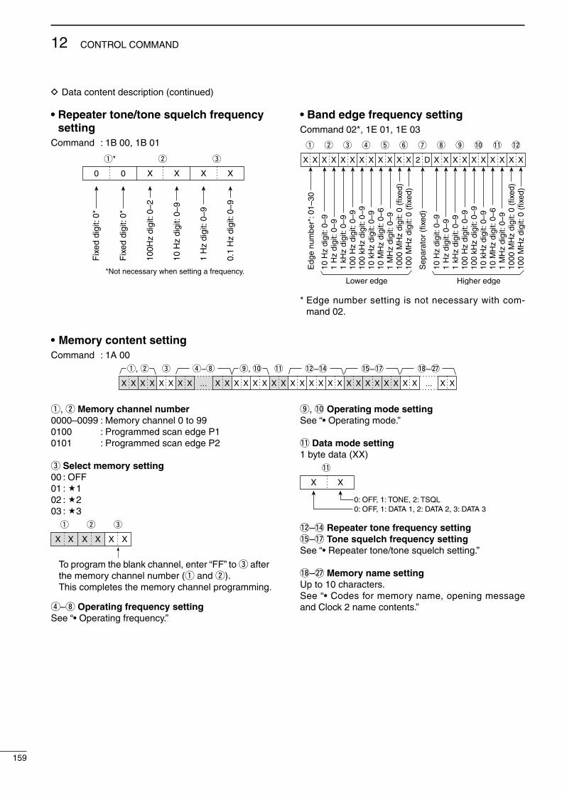
D Data content descrpton (contnued)
• Repeater tone/tone squelch frequency setting
Command : 1B 00, 1B 0110
0Hz
digi
t: 0–
2
10 H
z di
git:
0–9
1 H
z di
git:
0–9
0.1
Hz
digi
t: 0–
9
Fix
ed d
igit:
0*
Fix
ed d
igit:
0*
q*
00 X X X
w e
X
*Not necessary when setting a frequency.
• Band edge frequency settingCommand 02*, 1E 01, 1E 03
q
X X X
w e r t y u i o !0 !1 !2
X X X X X X X X X 2 D X X X X X X X X X X
10 H
z di
git:
0–9
1 H
z di
git:
0–9
1 kH
z di
git:
0–9
100
Hz
digi
t: 0–
910
0 kH
z di
git:
0–9
10 k
Hz
digi
t: 0–
910
MH
z di
git:
0–6
1 M
Hz
digi
t: 0–
910
00 M
Hz
digi
t: 0
(fix
ed)
100
MH
z di
git:
0 (f
ixed
)
10 H
z di
git:
0–9
1 H
z di
git:
0–9
1 kH
z di
git:
0–9
100
Hz
digi
t: 0–
910
0 kH
z di
git:
0–9
10 k
Hz
digi
t: 0–
910
MH
z di
git:
0–6
1 M
Hz
digi
t: 0–
910
00 M
Hz
digi
t: 0
(fix
ed)
100
MH
z di
git:
0 (f
ixed
)
Sep
arat
or (
fixed
)
Lower edge Higher edge
Edg
e nu
mbe
r*: 0
1–30
* Edge number settng s not necessary wth com-mand 02.
q, w Memory channel number0000–0099 : Memory channel 0 to 990100 : Programmed scan edge P10101 : Programmed scan edge P2
e Select memory setting00 : OFF01 : 102 : 203 : 3
To program the blank channel, enter “FF” to e after the memory channel number (q and w).This completes the memory channel programming.
q
X X X XX X
w e
r–i Operating frequency settingSee “• Operatng frequency.”
o, !0 Operating mode settingSee “• Operatng mode.”
!1 Data mode setting1 byte data (XX)
X X
!1
0: OFF, 1: TONE, 2: TSQL0: OFF, 1: DATA 1, 2: DATA 2, 3: DATA 3
!2–!4 Repeater tone frequency setting!5–!7 Tone squelch frequency settingSee “• Repeater tone/tone squelch settng.”
!8–@7 Memory name settingUp to 10 characters.See “• Codes for memory name, openng message and Clock 2 name contents.”
159
12 CONTROL COMMAND
• Memory content settingCommand : 1A 00
X
e r−i o, !0 !1 !2−!4 !5−!7
X X X ... ...X X X X X X X X X X X X X X X X X XX XX X X X X X X X
q, w !8−@7

General• Frequency coverage : (unt: MHz) Receve 0.030–60.000*1*2
Transmt 1.800–1.999*2, 3.500–3.999*2, 5.33050*3, 5.34650*3, 5.36650*3, 5.37150*3, 5.40350*3, 7.000–7.300*2, 10.100–10.150*2, 14.000–14.350*2, 18.068–18.168*2, 21.000–21.450*2, 24.890–24.990*2, 28.000–29.700*2, 50.000–54.000*2
*1Some frequency bands are not guaranteed. *2Dependng on verson. *3USA verson only.• Mode : USB, LSB, CW, RTTY, PSK,
AM, FM• No. of memory channels : 101 (99 regular, 2 scan edges)• Antenna connector type : SO-239 × 2 and phono jack
(RCA; 50 ø mpedance)• Temperature range : 0˚C to +50˚C (+32˚F to +122˚F)• Frequency stablty : Less than ±0.5 ppm 5 mn. after
power ON. (0˚C to +50˚C; +32˚F to +122˚F)
• Frequency resoluton : 1 Hz• Power supply : 13.8 V DC ±15% (negatve ground)• Power consumpton Transmt : Max. power 23 A Receve : Standby 3.0 A
Max. audo 3.5 A• Dmensons : 340(W) × 116(H) × 279.3(D) mm (projectons not ncluded) 133⁄8(W) × 49⁄16(H) × 11(D) n• Weght (approx.) : 10.0 kg; 22 lb• ACC 1 connector : 8-pn DIN connector• ACC 2 connector : 7-pn DIN connector• CI-V connector : 2-conductor 3.5 (d) mm (1⁄8″)• Dsplay : 5.8-nch (dagonal)
TFT color LCD
Transmitter• Output power (contnuously adjustable) SSB/CW/RTTY/FM : Less than 2 to 100 W AM : Less than 1 to 30 W• Modulaton system SSB : Dgtal PSN modulaton AM : Dgtal Low power modulaton FM : Dgtal Phase modulaton• Spurous emsson HF bands : Less than –50 dB 50 MHz band : Less than –63 dB• Carrer suppresson : More than 40 dB• Unwanted sdeband : More than 55 dB
suppresson • ∂TX varable range : ±9.999 kHz• Mcrophone connector : 8-pn connector (600 ø)• ELEC-KEY connector : 3-conductor 6.35(d) mm (1⁄4″)• KEY connector : 3-conductor 6.35(d) mm (1⁄4″)• SEND connector : Phono jack (RCA)• ALC connector : Phono jack (RCA)
Receiver• Receve system : Double superheterodyne
system• Intermedate frequences 1st : 64.455 MHz
2nd : 36 kHz• Senstvty (typcal) SSB, CW, RTTY : 0.15 µV (1.80–29.99 MHz)*1
(10 dB S/N) BW=2.4 kHz 0.12 µV (50.0–54.0 MHz)*2
AM (10 dB S/N) : 6.3 µV (0.1–1.799 MHz)*1
BW=6 kHz 2 µV (1.80–29.99 MHz)*1 1.6 µV (50.0–54.0 MHz)*2
FM (12 dB SINAD) : 0.5 µV (28.0–29.99 MHz)*1
BW=15 kHz 0.3 µV (50.0–54.0 MHz)*2
*1Pre-amp 1 s ON. *2Pre-amp 2 s ON.• Squelch senstvty (Pre-amp: ON) SSB : Less than 3.2 µV FM : Less than 0.3 µV• Selectvty (IF filter shape s set to SHARP.) SSB (BW: 2.4 kHz) : More than 2.4 kHz/–6 dB
Less than 3.8 kHz/–60 dB CW (BW: 500 Hz) : More than 500 Hz/–6 dB
Less than 900 Hz/–60 dB RTTY (BW: 350 Hz) : More than 350 Hz/–6 dB
Less than 650 Hz/–60 dB AM (BW: 6 kHz) : More than 6.0 kHz/–6 dB
Less than 15.0 kHz/–60 dB FM (BW: 15 kHz) : More than 12.0 kHz/–6 dB
Less than 20.0 kHz/–60 dB• Spurous and mage : More than 70 dB
rejecton rato (except IF through on 50 MHz band)• AF output power : More than 2.0 W at 10% (at 13.8 V DC) dstorton wth an 8 ø load• RIT varable range : ±9.999 kHz• PHONES connector : 3-conductor 6.35 (d) mm (1⁄4″)• External SP connector : 2-conductor 3.5 (d) mm
(1⁄8″)/8 ø• DSP ANF attenuaton : More than 30 dB
(wth 1 kHz sngle tone)• DSP NR attenuaton : More than 6 dB
(nose rejecton n SSB)
Antenna tuner• Matchng mpedance range HF bands : 16.7 to 150 ø unbalanced
(Less than VSWR 3:1) 50 MHz band : 20 to 125 ø unbalanced
(Less than VSWR 2.5:1)• Mnmum operatng nput : 8 W (HF bands)
power 15 W (50MHz band)• Tunng accuracy : VSWR 1.5:1 or less• Inserton loss : Less than 1.0 dB
(after tunng at RF power 100W)
Spurous sgnals may be dsplayed on the spectrum scope screen regardless of the transcever’s state (Tx or Rx). They are gener-ated n the scope crcut. Ths does not ndcate a transcever mal-functon.
All stated specfcatons are typcal and subject to change wthout notce or oblgaton.
13
160
SPECIFICATIONS AND OPTIONS
1
2
3
4
5
6
7
8
9
10
11
12
13
14
15
16
17
18
19
20
21

AH-4 hf automatic antenna tuner
Specally desgned to tune a long wre antenna for HF/50 MHz bands partc-ularly n portable or moble operaton. The “PTT tune” functon provdes sm-ple operaton.• Input power ratng: 120 W
AH-2b antenna element
A 2.5 m long antenna ele-ment for moble operaton wth the AH-4.• Frequency coverage
7–54 MHz band wth the AH-4
SM-20 desktop microphone
Undrectonal, electret mcrophone for base staton operaton. Includes [UP]/[DOWN] swtches, low cut swtch and mc gan control.
SM-50 desktop microphone
Undrectonal, dynamc mcrophone for base staton operaton. Includes [UP]/ [DOWN] swtches, a low cut swtch and mc gan control.
SP-23 external speaker
4 audo flters; headphone jack; can connect to 2 transcevers.• Input mpedance: 8 ø• Max. nput power: 4 W
HM-36 hand microphone
Hand mcrophone equpped wth [UP]/[DOWN] swtches.
CT-17 ci-v level converter unit
For remote transcever control usng a personal computer equpped wth an RS-232C port. You can change fre-quences, operatng mode, memory channels, etc., va your computer.
IC-PW1/EURO HF/50 MHz ALL BAND 1 kW LINEAR AMPLIFIER
Full-duty 1 kW lnear amplfer ncludng an automatc antenna tuner. Has auto-matc tunng and band selecton capablty. Full break-n (QSK) operaton s pos-sble. The amplfer/power supply unt and the remote control unt are separated.
PS-126 dc power supply
• Output voltage : 13.8 V DC• Max. output current : 25 A
161
13 SPECIFICATIONS AND OPTIONS
Options
• MB-121 carrying handle
Convenent when carryng the transcever.The same as that attached wth the transcever.
Approved Icom optonal equpment s desgned for optmal performance when used wth an Icom transcever.Icom s not responsble for the destructon or damage to an Icom trans-cever n the event the Icom transcever s used wth equpment that s not manufactured or approved by Icom.
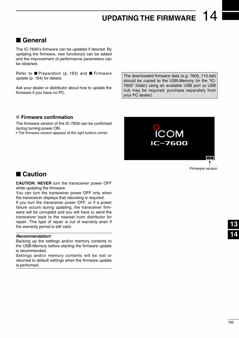
GeneralThe IC-7600’s frmware can be updated f desred. By updatng the frmware, new functon(s) can be added and the mprovement of performance parameters can be obtaned.
Refer to Preparaton (p. 163) and Frmware update (p. 164) for detals.
Ask your dealer or dstrbutor about how to update the frmware f you have no PC.
D Firmware confirmationThe frmware verson of the IC-7600 can be confrmed durng turnng power ON. • The frmware verson appears at the rght bottom corner.
CautionCAUTION: NEVER turn the transcever power OFF whle updatng the frmware. You can turn the transcever power OFF only when the transcever dsplays that rebootng s requred.If you turn the transcever power OFF, or f a power falure occurs durng updatng, the transcever frm-ware wll be corrupted and you wll have to send the transcever back to the nearest Icom dstrbutor for repar. Ths type of repar s out of warranty even f the warranty perod s stll vald.
Recommendation!Backng up the settngs and/or memory contents to the USB-Memory before startng the frmware update s recommended.Settngs and/or memory contents wll be lost or returned to default settngs when the frmware update s performed.
14
162
UPDATING THE FIRMWARE
1
2
3
4
5
6
7
8
9
10
11
12
13
14
15
16
17
18
19
20
21
The downloaded frmware data (e.g. 7600_110.dat) should be coped to the USB-Memory (n the “IC-7600” folder) usng an avalable USB port (a USB hub may be requred; purchase separately from your PC dealer).
Frmware verson

PreparationD FirmwareThe latest frmware can be downloaded from the Icom home page va the Internet. Access the followng URL to download the latest frmware. http://www.com.co.jp/world/ndex.html
InformationThe downloaded frmware data (e.g. 7600_110.dat) should be coped to the USB-Memory (n the “IC-7600” folder) usng an avalable USB port (a USB hub may be requred; purchase separately from your PC dealer).
D File downloadingqAccess the followng URL. http://www.com.co.jp/world/ndex.html wClck [Support] button.e Clck “Frmware Updates/Software Downloads” lnk
then clck the firmware file lnk.r Clck the desred frmware fle lnk n the IC-7600
group.
t Read “Regardng ths Download Servce” carefully, then clck [AGREE].
y Clck [Save] n the dsplayed Fle Download dalog.
u Select the desred locaton n whch you want to save the frmware, then clck [Save] n the ds-played Fle Download dalog.
• Fle download starts.i After the download s completed, extract the fle. • The frmware s compressed n “zp” format, respec-
tvely. • When updatng the transcever usng wth the USB-
Memory, copy the extracted frmware (e.g. 7600_110.dat) to the USB-Memory IC-7600 folder.
• The USB-Memory must have been formatted by the IC-7600. (p. 143)
Click
Read carefully
Click
Select the savinglocation
Click7600_110.dat
163
14 UPDATING THE FIRMWARE

The transcever dsplays ts frmware verson nforma-ton after turnng power ON, f the openng message screen ndcaton capablty s ON. (p. 127)
q Copy the downloaded frmware data nto the “IC-7600” folder of the USB-Memory.
• The USB-Memory must have been formatted by the IC-7600.
w Insert the USB-Memory nto the [USB] (A) connec-tor on the front panel.
e Push [EXIT/SET] several tmes to close any mult-functon screens, f necessary.
r Push [SET] (F-6) to select the set mode menu screen.
t Push [USB] (F-6) to select the USB Memory set menu.
y Push and hold [FIRM UP] (F-3) for 1 sec.
u Read the dsplayed precauton carefully. • Push [Y] (F-1) or [Z] (F-2) to scroll the dsplay. • Push [CANCEL] (F-6) to cancel the frmware updatng.
i After you read and understand all of the precau-tons, push [OK] (F-5).
• [OK] (F-5) appears only followng the precautons. • Push [CANCEL] (F-6) to cancel the frmware updatng.
o Push [Y] (F-2) or [Z] (F-3) to select the frmware fle, then push [FIRM UP] (F-4).
!0 Read the dsplayed precautons carefully.
!1 If you agree, push and hold [OK] (F-5) for 1 sec. to start the frmware update.
• Push [CANCEL] (F-6) to cancel the frmware updatng.
!2 Whle loadng the frmware from the USB-Memory, the dalog to the rght s dsplayed.
F-1 F-2
F-5 F-6
EXIT/SET
USBSET CANCEL
DIR/FILE
OK
F-4
FIRM UP
F-3
FIRM UP
[USB] (A)
/ /
/ /
/
Contnued on the next page.
Firmware update
164
14UPDATING THE FIRMWARE
1
2
3
4
5
6
7
8
9
10
11
12
13
14
15
16
17
18
19
20
21

Frmware update (Contnued)
!3 After the frmware loadng s completed, the trans-cever automatcally starts the update, and the da-log at rght s dsplayed.
RWARNING: NEVER turn the IC-7600 power OFF at ths stage.The transcever frmware wll be corrupted.
!4 When the dalog dsappears, the precauton to the rght s dsplayed.
!5 Read the precauton carefully, and then push [OK] (F-5).
• Return to the USB Memory set menu.
!6 Push [POWER] to turn the IC-7600 power OFF, then ON agan.
!7 Dependng on the update, one or two dalog boxes to the rght appear n sequence.
RWARNING: NEVER turn the IC-7600 power OFF at ths stage. The transcever frmware wll be corrupted.
!8 After the dalog dsappears, the frmware updat-ng s completed and the normal operaton screen appears.
165
14 UPDATING THE FIRMWARE

INSTALLATION NOTESFor amateur base staton nstallatons t s recom-mended that the forward clearance n front of the an-tenna array s calculated relatve to the EIRP (Effec-tve Isotropc Radated Power). The clearance heght below the antenna array can be determned n most cases from the RF power at the antenna nput term-nals.
As dfferent exposure lmts have been recommended for dfferent frequences, a relatve table shows a gudelne for nstallaton consderatons.
Below 30 MHz, the recommended lmts are specfied n terms of V/m or A/m fields as they are lkely to fall wthn the near-feld regon. Smlarly, the antennas may be physcally short n terms of electrcal length and that the nstallaton wll requre some antenna matchng devce whch can create local, hgh ntensty magnetc felds. Analyss of such MF nstallatons s best consdered n assocaton wth publshed gud-ance notes such as the FCC OET Bulletn 65 Edton 97-01 and ts annexes relatve to amateur transmtter nstallatons.The EC recommended lmts are almost dentcal to the FCC specfied ‘uncontrolled’ lmts and tables exst that show pre-calculated safe dstances for dfferent antenna types for dfferent frequency bands. Further nformaton can be found at http://www.arrl.org/.
• Typical amateur radio installationExposure dstance assumes that the predomnant ra-daton pattern s forward and that radaton vertcally downwards s at unty gan (sdelobe suppresson s equal to man lobe gan). Ths s true of almost every gan antenna today. Exposed persons are assumed to be beneath the antenna array and have a typcal heght of 1.8 m.
The fgures assume the worst case emsson of a constant carrer.
For the bands 10 MHz and hgher the followng power densty lmts have been recommended: 10–50 MHz 2 W/sq m
Vertical clearance by EIRP output 1 Watts 2.1 m 10 Watts 2.8 m 25 Watts 3.4 m 100 Watts 5 m 1000 Watts 12 m
Forward clearance by EIRP output 100 Watts 2 m 1000 Watts 6.5 m 10,000 Watts 20 m 100,000 Watts 65 m
In all cases any possble rsk depends on the trans-mtter beng actvated for long perods. (actual recom-mendaton lmts are specfied as an average durng 6 mnutes) Normally the transmtter s not actve for long perods of tme. Some rado lcenses wll requre that a tmer crcut automatcally cuts off the transmtter after 1–2 mnutes etc.
Smlarly some modes of transmsson, SSB, CW, AM etc. have a lower ‘average’ output power and the as-sessed rsk s even lower.
Versons of the IC-7600 whch dsplay the “CE” symbol on the seral number label, comply wth the essental requrements of the European Rado and Telecommunca-ton Termnal Drectve 1999/5/EC.
Ths warnng symbol ndcates that ths equpment operates n non-harmonsed frequency bands and/or may be subject to lcensng condtons n the country of use. Be sure to check that you have the correct verson of ths rado or the correct pro-grammng of ths rado, to comply wth na-tonal lcensng requrement.
• List of Country codes (ISO 3166-1)Country Codes Country Codes
1234567891011121314151617
AustraBelgumBulgaraCroataCzech RepublcCyprusDenmarkEstonaFnlandFranceGermanyGreeceHungaryIcelandIrelandItalyLatva
ATBEBGHRCZCYDKEEFIFRDEGRHUISIEITLV
18192021222324252627282930313233
LechtenstenLthuanaLuxembourgMaltaNetherlandsNorwayPolandPortugalRomanaSlovakaSlovenaSpanSwedenSwtzerlandTurkeyUnted Kngdom
LILTLUMTNLNOPLPTROSKSIESSECHTRGB
15
166
CE
1
2
3
4
5
6
7
8
9
10
11
12
13
14
15
16
17
18
19
20
21
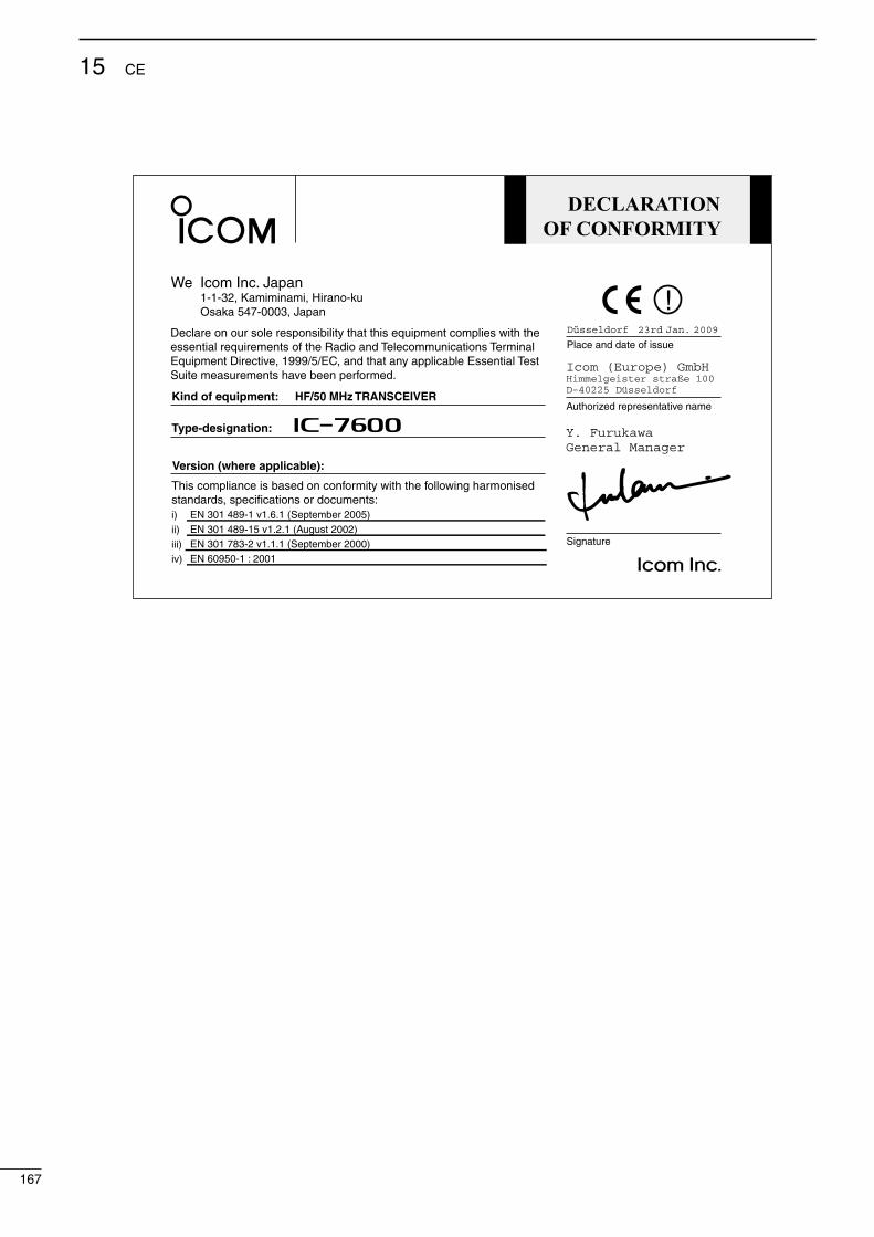
DECLARATIONOF CONFORMITY
We Icom Inc. Japan1-1-32, Kamiminami, Hirano-kuOsaka 547-0003, Japan
Kind of equipment: HF/50 MHz TRANSCEIVER
Type-designation: iC- 7600
Signature
Authorized representative name
Place and date of issueDeclare on our sole responsibility that this equipment complies with theessential requirements of the Radio and Telecommunications Terminal Equipment Directive, 1999/5/EC, and that any applicable Essential TestSuite measurements have been performed.
Version (where applicable):
This compliance is based on conformity with the following harmonised standards, specifications or documents:i)ii)iii)iv)
Düsseldorf 23rd Jan. 2009
Y. FurukawaGeneral Manager
EN 301 489-1 v1.6.1 (September 2005)EN 301 489-15 v1.2.1 (August 2002) EN 301 783-2 v1.1.1 (September 2000) EN 60950-1 : 2001
167
15 CE

168
MEMO
1
2
3
4
5
6
7
8
9
10
11
12
13
14
15
16
17
18
19
20
21

169
MEMO
170
MEMO
1
2
3
4
5
6
7
8
9
10
11
12
13
14
15
16
17
18
19
20
21

171
MEMO
172
MEMO
1
2
3
4
5
6
7
8
9
10
11
12
13
14
15
16
17
18
19
20
21

1-1-32 Kammnam, Hrano-ku, Osaka 547-0003, Japan
A-6722H-1EX-qPrnted n Japan© 2009 Icom Inc.
< Intended Country of Use >ATFIITPLGBRO
BEFRLVPTISTR
CYDELTSKLIHR
CZGRLUSINO
DKHUMTESCH
EEIENLSEBG
< Intended Country of Use >ATFIITPLGBRO
BEFRLVPTISTR
CYDELTSKLIHR
CZGRLUSINO
DKHUMTESCH
EEIENLSEBG
< Intended Country of Use >ATFIITPLGBRO
BEFRLVPTISTR
CYDELTSKLIHR
CZGRLUSINO
DKHUMTESCH
EEIENLSEBG
< Intended Country of Use >ATFIITPLGBRO
BEFRLVPTISTR
CYDELTSKLIHR
CZGRLUSINO
DKHUMTESCH
EEIENLSEBG
IC-7600 #10(France)
< Intended Country of Use >ATFIITPLGBRO
BEFRLVPTISTR
CYDELTSKLIHR
CZGRLUSINO
DKHUMTESCH
EEIENLSEBG
IC-7600 #03(Europe)
IC-7600 #04(Europe-1)
IC-7600 #05(Spain)
IC-7600 #09(Italy)


![COMMUNICATIONS RECEIVER iC-r8500 - アイコム …1 MEMORY SET SWITCH [M-SET] (p. 19) Used to ‘copy and paste’ the displayed frequency into another memory channel. • The first](https://static.fdocuments.net/doc/165x107/5b1de4c07f8b9ac96a8b8410/communications-receiver-ic-r8500-1-memory-set-switch-m-set-p.jpg)