IBP 114 04 RELIABLE PIPELINE REPAIR SYSTEM FOR VERY …
9
______________________________ 1 Master’s Degree, Mechanical Engineering – Oceaneering International, Inc. 2 M.B.A. & Bachelor’s Degree, Mechanical Engineering – Oceaneering International, Inc IBP 114 04 RELIABLE PIPELINE REPAIR SYSTEM FOR VERY LARGE PIPE SIZES John N. Charalambides 1 , Alexandre Barreto de Sousa 2 Copyright 2004, Instituto Brasileiro de Petróleo e Gás - IBP This Technical Paper was prepared for presentation at the Rio Oil & Gas Expo and Conference 2004, held between 4 and 7 October 2004, in Rio de Janeiro. This Technical Paper was selected for presentation by the Technical Committee of the event according to the information contained in the abstract submitted by the author(s). The contents of the Technical Paper, as presented, were not reviewed by IBP. The organizers are not supposed to translate or correct the submitted papers. The material as it is presented, does not necessarily represent Instituto Brasileiro de Petróleo e Gás’ opinion, nor that of its Members or Representatives. Authors consent to the publication of this Technical Paper in the Rio Oil & Gas Expo and Conference 2004 Annals. Abstract The oil and gas industry worldwide has been mainly depending on the long-term reliability of rigid pipelines to ensure the transportation of hydrocarbons, crude oil, gas, fuel, etc. Many other methods are also utilized onshore and offshore (e.g. flexible lines, FPSO’s, etc.), but when it comes to the underwater transportation of very high volumes of oil and gas, the industry commonly uses large size rigid pipelines (i.e. steel pipes). Oil and gas operators learned to depend on the long-lasting integrity of these very large pipelines and many times they forget or disregard that even steel pipelines degrade over time and more often that that, they are also susceptible to various forms of damage (minor or major, environmental or external, etc.). Over the recent years the industry had recognized the need of implementing an “emergency repair plan” to account for such unforeseen events and the oil and gas operators have become “smarter” by being “pro-active” in order to ensure “flow assurance”. When we consider very large diameter steel pipelines such as 42” and 48” nominal pipe size (NPS), the industry worldwide does not provide “ready-made”, “off-the-shelf” repair hardware that can be easily shipped to the offshore location and effect a major repair within acceptable time frames and avoid substantial profit losses due to “down-time” in production. The typical time required to establish a solid repair system for large pipe diameters could be as long as six or more months (depending on the availability of raw materials). This paper will present in detail the Emergency Pipeline Repair Systems (EPRS) that Oceaneering successfully designed, manufactured, tested and provided to two major oil & gas operators, located in two different continents (Gulf of Mexico, U.S.A. and Arabian Gulf, U.A.E.), for two different very large pipe sizes (42” & 48” Nominal Pipe Sizes). The technical advantages, basic principle of operation, risk mitigation, emergency response plans and long term reliability of these systems (EPRS) will be explained and presented in detail. 1. Introduction 1.1 The Problem Definition Flow assurance in all hydrocarbon carrying pipelines and flowlines of any size, rating location or service is of high importance to the operator because of the associated operational and mostly financial consequences. Over the years, the industry has developed very complex and efficient routine inspection and maintenance programs utilizing new technologies that allow the operator to detect a problem associated with the damage of a pipeline and develop plans for immediate rectification prior to the damage extending to limits that a repair/intervention is inevitable. The damage or failure modes of pipelines can be classified/divided into various categories depending on:
Transcript of IBP 114 04 RELIABLE PIPELINE REPAIR SYSTEM FOR VERY …

______________________________ 1 Master’s Degree, Mechanical Engineering – Oceaneering International, Inc. 2 M.B.A. & Bachelor’s Degree, Mechanical Engineering – Oceaneering International, Inc
IBP 114 04 RELIABLE PIPELINE REPAIR SYSTEM FOR VERY
LARGE PIPE SIZESJohn N. Charalambides1, Alexandre Barreto de Sousa 2
Copyright 2004, Instituto Brasileiro de Petróleo e Gás - IBP This Technical Paper was prepared for presentation at the Rio Oil & Gas Expo and Conference 2004, held between 4 and 7 October 2004, in Rio de Janeiro. This Technical Paper was selected for presentation by the Technical Committee of the event according to the information contained in the abstract submitted by the author(s). The contents of the Technical Paper, as presented, were not reviewed by IBP. The organizers are not supposed to translate or correct the submitted papers. The material as it is presented, does not necessarily represent Instituto Brasileiro de Petróleo e Gás’ opinion, nor that of its Members or Representatives. Authors consent to the publication of this Technical Paper in the Rio Oil & Gas Expo and Conference 2004 Annals. Abstract
The oil and gas industry worldwide has been mainly depending on the long-term reliability of rigid pipelines to ensure the transportation of hydrocarbons, crude oil, gas, fuel, etc. Many other methods are also utilized onshore and offshore (e.g. flexible lines, FPSO’s, etc.), but when it comes to the underwater transportation of very high volumes of oil and gas, the industry commonly uses large size rigid pipelines (i.e. steel pipes).
Oil and gas operators learned to depend on the long-lasting integrity of these very large pipelines and many times they forget or disregard that even steel pipelines degrade over time and more often that that, they are also susceptible to various forms of damage (minor or major, environmental or external, etc.).
Over the recent years the industry had recognized the need of implementing an “emergency repair plan” to account for such unforeseen events and the oil and gas operators have become “smarter” by being “pro-active” in order to ensure “flow assurance”.
When we consider very large diameter steel pipelines such as 42” and 48” nominal pipe size (NPS), the industry worldwide does not provide “ready-made”, “off-the-shelf” repair hardware that can be easily shipped to the offshore location and effect a major repair within acceptable time frames and avoid substantial profit losses due to “down-time” in production. The typical time required to establish a solid repair system for large pipe diameters could be as long as six or more months (depending on the availability of raw materials).
This paper will present in detail the Emergency Pipeline Repair Systems (EPRS) that Oceaneering successfully designed, manufactured, tested and provided to two major oil & gas operators, located in two different continents (Gulf of Mexico, U.S.A. and Arabian Gulf, U.A.E.), for two different very large pipe sizes (42” & 48” Nominal Pipe Sizes). The technical advantages, basic principle of operation, risk mitigation, emergency response plans and long term reliability of these systems (EPRS) will be explained and presented in detail. 1. Introduction 1.1 The Problem Definition
Flow assurance in all hydrocarbon carrying pipelines and flowlines of any size, rating location or service is of high importance to the operator because of the associated operational and mostly financial consequences. Over the years, the industry has developed very complex and efficient routine inspection and maintenance programs utilizing new technologies that allow the operator to detect a problem associated with the damage of a pipeline and develop plans for immediate rectification prior to the damage extending to limits that a repair/intervention is inevitable. The damage or failure modes of pipelines can be classified/divided into various categories depending on:

Rio Oil & Gas Expo and Conference 2004
2
o Extend of Damage: major vs. minor A minor damage is defined as that damage that can be rectified/repaired without having to cut and replace the affected section of the pipeline (such as a pin hole formation due to corrosion). A major damage requires the replacement of the affected section with a spool piece section (a spool piece is a section of a pipe with two flanges at the ends). An example of a major damage is the rupture of a pipeline during hydrostatic testing or buckling due to excessive external load application.
o Reason of Damage: external or internal factors External factors are those caused by third parties such as, anchor drag, fishing nets, mudslides, crushing with heavy equipment, etc. Internal factors we mainly consider any mechanical damage such as severe corrosion or erosion that results in wall thickness loss higher than the allowable by the design code, thermal expansion loads, fatigue issues, movement of the pipeline, and or other accidents (e.g. dragging of a pipeline over an existing one, etc.).
o Location of Damage: shallow vs. deepwater This is defined based on the location of the damaged section of the pipeline. Shallow water repairs have been implemented for decades now using various conventional methods (e.g. wet welding, dry welding, spool piece replacements, mechanical connectors, hot taps, etc.). Deepwater pipeline repairs is a subject extensively addressed within the last five years due to the increased amount of rigid pipelines installed in water depths attainable only by Remotely Operated Vehicles (ROV) that require the prior development of suitable tooling packages and specialized procedures.
The size and operating envelop of the pipeline can also be a factor to be considered during the selection
process of the most appropriate repair methodology to be followed. For example, a 4” pipeline in shallow water depth (i.e. attainable my a diver up to 1100 f WD), can be easily lifted to the surface by the support vessel, repaired by dry welding and re-laid subsea. This cannot be done in a 42” or 48” Nominal Pipe Size (NPS) due to the obvious reasons (weight, vessel handling requirements, risk of damage during lifting, etc.). 1.2 The Solution Description
The repair method to be followed for a specific pipeline is evaluated based on the type and extend of the damage suffered as described above:
o Size and Operating Envelop of the pipeline (i.e. OD, thickness, material, service, pressure, temperature, water depth, etc.)
o Extend and severity of Damage o Urgency of repair execution
In cases where a pipeline system is rated higher than ASME/ANSI Class 1500 (MAOP=3750 psi), and even if
the damage mode is minor, a clamp type repair can not be executed because repair clamps are not available in classes higher than 1500.
In the very far past, pipelines in shallow water were executed using Hyperbaric Welded Repair methods that required extensive planning (with high safety risks), skilled personnel (diver welders), utilizing complex repair hardware (hyperbaric chamber, dry welding habitat, etc.) that also required the use of heavy lift barges making this repair method long to execute and very expensive (Fig. 1 & 2).
Figure 2 Figure 1
Rio Oil & Gas Expo and Conference 2004
3
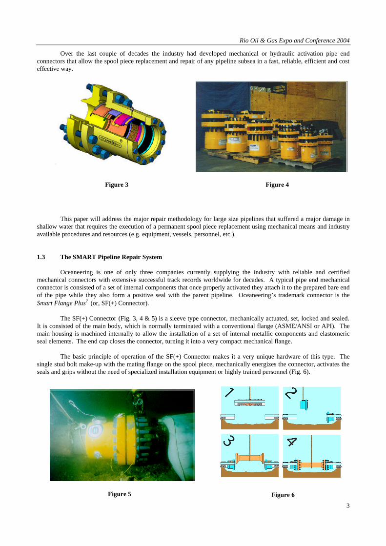
Over the last couple of decades the industry had developed mechanical or hydraulic activation pipe end connectors that allow the spool piece replacement and repair of any pipeline subsea in a fast, reliable, efficient and cost effective way.
This paper will address the major repair methodology for large size pipelines that suffered a major damage in
shallow water that requires the execution of a permanent spool piece replacement using mechanical means and industry available procedures and resources (e.g. equipment, vessels, personnel, etc.). 1.3 The SMART Pipeline Repair System Oceaneering is one of only three companies currently supplying the industry with reliable and certified mechanical connectors with extensive successful track records worldwide for decades. A typical pipe end mechanical connector is consisted of a set of internal components that once properly activated they attach it to the prepared bare end of the pipe while they also form a positive seal with the parent pipeline. Oceaneering’s trademark connector is the Smart Flange Plus? (or, SF(+) Connector). The SF(+) Connector (Fig. 3, 4 & 5) is a sleeve type connector, mechanically actuated, set, locked and sealed. It is consisted of the main body, which is normally terminated with a conventional flange (ASME/ANSI or API). The main housing is machined internally to allow the installation of a set of internal metallic components and elastomeric seal elements. The end cap closes the connector, turning it into a very compact mechanical flange. The basic principle of operation of the SF(+) Connector makes it a very unique hardware of this type. The single stud bolt make-up with the mating flange on the spool piece, mechanically energizes the connector, activates the seals and grips without the need of specialized installation equipment or highly trained personnel (Fig. 6).
Figure 3 Figure 4
Figure 5 Figure 6

Rio Oil & Gas Expo and Conference 2004
4
Once properly installed over the pipe end, it forms a structural attachment stronger than a butt weld that won’t allow the connector to come off after installation, unless special considerations are taken into account from the design stage. At the same time, the connector forms four positive seals with the pipeline, two primary seals (main seal and RTJ/RF gasket) and two secondary seals (between piston and mating flange and between piston and pipe). 1.4 Selecting the Right Connection System The SF(+) Connector offers a few significant features that make it the preferred solution over similar products, especially for large size pipelines, such as:
o Simplicity: It is the simplest most “friendly” mechanical connector available in the market today. It is a “sleeve type” connector that easily slides over the bare end of pipe. The pipe end preparation required is minimum and the cut of the pipeline does not have to be straight.
o Ease of Installation: The single stud bolt make-up with the mating flange on the spool piece, mechanically energizes the connector, activates the seals and grips without the need of specialized installation equipment or highly trained personnel, making the repair cost effective.
o Rotational Capability: It can freely rotate around the pipe for easy bolt circle match-up with the mating flange on the spool piece. This allows for the spool piece to be as long as needed regardelss of pipe size. The need of a swivel ring flange is eliminated, reducing the overall cost of hardware required for the repair.
o Length of Compensation: It is “very forgiving” when it comes to spool piece measurements taken subsea. Every connector possesses a certain length of compensation by means of the piston critical length that allows short spool pieces to be used. For spool piece repairs the available length of compensation is twice as much.
o Double Seals: It comes with a double seal mechanism that allows not only testing of the seal integrity of the main seal formed with the pipe OD but also checks the RTJ/RF gasket seal, thus allowing the operator to commission the pipeline without having to hydrostatically test the entire system after the repair.
o Design Superiorities: By design the connector offers the following technical advantages: o It controls the amount of pressure/load resulting from the radial expansion of the grips (slip & cone
mechanism), by applying predetermined and controlled teeth penetration. o The back-up and segmented rings, once energized correctly “lock” the Smart Flange Plus Connector on
the pipeline. Once installed, it does not come off - the pipeline will have to be cut for the connector to be removed. If required, the Smart Flange Plus Connector can be “readily re-usable”.
o The “load limiting device” inside the Smart Flange Plus Connector controls the damage a pipeline can suffer by accidental unwanted application of bolt loads.
o The Smart Flange Plus Connector can sustain externally applied axial loads and bending moments. The connector (as a minimum) is designed in accordance with the minimum axial load and bending moment capabilities of the parent pipe.
o The two pairs of the seal limiting rings provide a fixed envelope where the elastomeric element is going to be compressed and avoid any unwanted element extrusion that could result in a possible leak path over the years.
2. Project Specific Execution Now that we have understood the “problem” and the “solution” associated with the repair of subsea pipelines, we will present and analyze the equipment designed, tested and supplied as an EPRS for two large size pipeline transportation systems, operating at two different locations. What is common in both systems was the selection of the operator to use the Smart Flange Plus Connectors versus similar products, due to the unique advantages described above and the proven reliability that comes with it. 2.1 The 48” NPS Pipeline Transportation System & EPRS – Technical Specifications This system is owned and operated in the Gulf of Mexico (U.S.A.) by local oil and gas company who presently operates approximately 100 miles of 48” NPS crude oil pipelines of various material thickness and ASME/ANSI ratings. The Pipeline Technical Specification and Service Conditions stated for the design of the connectors were as follows:

Rio Oil & Gas Expo and Conference 2004
5
o Pipe Size: 48” NPS (OD=48.0”) o Pipe Wall thickness range: 0.375” to 0.625” and ovality per API Spec 5L allowable limits o Material Specification: API 5L Grade X-60 o Maximum Design Pressure: 1,125 psi o System Limiting Pressure Rating: 720 psi (ASME/ANSI Class 300) o Suitability for crude oil service with 3.25% maximum sulfur content o A crude oil temperature range from 60 deg. to 100 deg. F o Crude oil containing in excess of 70-PPM H2S
Based on the above criteria the operator opted to procure the following hardware as part of their EPRS:
o 2 Ea. - 48” ASME/ANSI Class 600 Raised-Face (RF) NACE Mechanical Pipe End Connectors (Oceaneering Smart Flange Plus Connectors with Test Port Facilities)
o 2 Ea. - 48” ASME/ANSI Class 600 Raised-Face (RF) Weld Neck Flanges (for mating to the Smart Flanges) o 2 Ea. - 48” ASME/ANSI Class 600 Raised-Face (RF) NACE Ball Joint Misalignment Flanges that provide
both angular and rotary alignment capability for mating to the Smart Flanges (Oceaneering A-Con Variable Alignment Connectors)
o 2 Ea. – 48” ASME/ANSI Class 600 Raised-Face (RF) Blind Flanges o 1 Ea. – Gage Template for use in determining the suitability of preparation for installation of a Smart Flange
on a piece of 48” OD pipe o 64 Ea. – Stud-Bolt/Nuts Sets for the connection of the 48” ASME/ANSI Class 600 Raised-Face (RF)
Flanges (provides for 50% spares) o 8 Ea. – RF Spiral Wound Flexitallic Gaskets. (provides a gasket and a spare each for four flange sets)
Based on the specified pipeline system operating envelope the EPRS was designed and fabricated in accordance with the following technical specification:
o Nominal Pipe Size: 48” (OD=48.0”) o Wall Thickness: 0.375” to 0.625” o Maximum Appowable Operating Pressure: 1,125 psi o Maximum Test Pressure: 1,406 psi o Maximum Design Tempeture: 200 deg. F o Minimum Design Tempeture: minus 20 deg. F o Service: Sour Crude Oil o Desgin Codes, Standards & Specifications:
o ASME/ANSI B16.47, Large Diameter Pipe Flanges o API SPEC 6H, Specification on End Closures, Connectors and Swivels o ANSI/API SPEC 5L, Specification for Line Pipe o ASME Pressure Vessel Code, Section VIII, Divisions 1 & 2 o ASME/ANSI B18.2.1, Square and Hex Bolts and Screws Inch Series. o ASME/ANSI B16.20, Metallic Gaskets for Pipe Flanges - Ring Joint, Spiral Wound and Jacketed o NACE Standard MR0175, Sulfide Stress Cracking Resistant Metallic Materials for Oilfield
Equipment o 49 CFR 195 Transportation of Hazardous Liquids by Pipeline o Customer Supplied Technical Specification (S-000-CP-001 rev. 11)
o Certification: o ISO 9001:2000 - OTS, Accredited by the Dutch Council for Certification o Det Norske Veritas (DNV) Design, Testing & Product Approval o EN 10204 Section 3.1.B (DIN 50049), Inspection Documents for the Delivery of Metallic Products
2.2 The 42” NPS Pipeline Transportation System & EPRS – Technical Specifications This system is operated in the Arabian Gulf for a major oil and gas operator in the Emirate of Abu Dhabi. The 42” NPS is the most important and larger sour crude oil carrying pipeline for this operator. The Pipeline Technical Specification and Service Conditions stated for the design of the connectors were as follows:
o Pipe Size: 42” NPS (OD=42.0”) o Wall Thickness: 14.27 mm (0.562”) o Water Depth: 5 to 30 m WD o Service: Crude Oil containing H2S (Soure Service)

Rio Oil & Gas Expo and Conference 2004
6
o Design Pressure: 1,120 psi o Test Pressure: 1,500 psi o Operating Pressure: 200 psi o Operating Temperature: 122 deg. F (50 deg. C) o Material: API Spec 5L Grade X-65
Based on the specified pipeline system operating envelope the EPRS was designed and fabricated in accordance with the following technical specification:
o Nominal Pipe Size: 42” (OD=42.0”) o Wall Thickness: 14.27 mm (0.562”) o Maximum Appowable Operating Pressure: 200 psi o Maximum Test Pressure: 1,500 psi o Maximum Design Tempeture: 200 deg. F o Minimum Design Tempeture: minus 20 deg. F o Service: Sour Crude Oil o Desgin Codes, Standards & Specifications:
o ASME/ANSI B16.47, Large Diameter Pipe Flanges o API SPEC 6H, Specification on End Closures, Connectors and Swivels o ANSI/API SPEC 5L, Specification for Line Pipe o ASME Pressure Vessel Code, Section VIII, Divisions 1 & 2 o ASME/ANSI B18.2.1, Square and Hex Bolts and Screws Inch Series. o ASME/ANSI B16.20, Metallic Gaskets for Pipe Flanges - Ring Joint, Spiral Wound and Jacketed o NACE Standard MR0175, Sulfide Stress Cracking Resistant Metallic Materials for Oilfield
Equipment o Customer Supplied Technical Specification (ZO-TS-Y-02020)
o Certification: o ISO 9001:2000 - OTS, Accredited by the Dutch Council for Certification o Det Norske Veritas (DNV) Design, Testing & Product Approval o EN 10204 Section 3.1.B (DIN 50049), Inspection Documents for the Delivery of Metallic Products
3. EPRS Development Process 3.1 Design and Manufacture
Both EPRS’s for the 42”and 48” pipeline repair systems where designed based on the well proven and widely used concept of Oceaneering’s proprietary equipment, Smart Flange Plus Connectors and A-Con Variable Alignment Connectors manufactured in Houston. This design took into consideration the operating envelope of the pipeline system in selecting the appropriate material specifications for the connectors and match the parent pipe (Fig. 7 & 8).
Figure 7 (3-D Model) Figure 8 (Design Drawing)

Rio Oil & Gas Expo and Conference 2004
7
3.2 Factory Acceptance Testing
Once the connectors were fabricated and properly inspected (per ISO 9001:2000), they underwent an extensive Factory Acceptance Testing at the manufacturer’s plant. The testing program covered both, dry-shop testing as well as wet-tank testing (Fig. 9 to 15). This testing program covered and successfully proved the following:
o Seal Integrity Testing of all seals formed (primary and secondary) o Structural Integrity Testing of the equipment o Hydrostatic Strength Testing of the equipment o Axial Movement Testing of the equipment
FAT – 48” NPS EPRS
Figure 13
Figure 9 Figure 10
Figure 11 Figure 12

Rio Oil & Gas Expo and Conference 2004
8
3.3 Storage & Delivery
Upon completion of the extensive testing program all equipment was properly coated per customers and manufacturers approved specifications and prepared for long-term storage. The operator in the GoM for the 48” EPRS (Fig. 16) had selected to use the manufacturer to store and maintain the equipment in the manufacturer’s facilities and also implemented a Service Contract with Oceaneering to act as a diving contractor to supply diving personnel and related diving equipment for the installation of the supplied fittings. Oceaneering has the capability of providing a wide range of services needed for installation in an offshore environment.
The owner of the 42” EPRS (Fig. 17) operating in Abu Dhabi chose to have the equipment shipped to their
warehouses where Oceaneering’s local office in Abu Dhabi provided all the support needed to properly assemble the shipped units and prepare/pack them suitable for long-term storage. This operator already ahs an alliance for diving services with another contractor in the region. Ocenaeering deos not provide diving services anywhere outside the U.S.A. but Oceaneering’s pipeline repair systems could be easily utilized by any third party diving contractor. Oceaneering’s local offices operating in excess of forty countries worldwide can provide Technical and Offshore Service Support any time.
Figure 14 (FAT – 42” NPS EPRS) Figure 15 (FAT – 42” NPS EPRS)
Figure 16
(48” NPS EPRS)
Figure 17
(42” NPS EPRS)

Rio Oil & Gas Expo and Conference 2004
9
4. Conclusions Oceaneering had proven to the oil and gas offshore producing industry worldwide that it has the cabapility to supply rerlaible pipeline repair systems for any pipe size, any operating envelope at any part of the world. The operator can now rest assure that in the event of any problem, a suitable solution could be provided. Both EPRS’s took a considerable amount of time to complete from design to storage. Each system took approximately six calendar months to complete and each process was closely monitored by the clients’ appointed third party inspectors in addition to Oceaneering utilizing DNV to certified the equipment and get them covered under the existing Type Approval ceertificate of the entire Smart Flange Plus Connector proiduct line, certifiying them as permant repair hardware. This demonstrates the ability of the contractor to provide a suitable solution to the operators’ needs but also stated the pro-active approach of the respective operators to act ahead of the problem, once they appreciated that a sound solution to the repair of 42” and/or 48” pipelien syustem is not something that could be provided “after the fact” and having in mind the long lead required to design, procure and supply certified repair systems. It’s worth mentioning that Oceaneering has extended its manufacturing cabapilities in Pipeline Repair Systems by providing similar equipment suitable for the on-bottom repair of pipelines operating in deepwater. In addition, Oceaneering now manufcatures and supplies the Brazilian market with 100% locally made (national) Smart Flange Plus Connectors and A-Con Variable Alignment Connectors. References CHARALAMBIDES, N. JOHN, Offshore Repair of Deepwater High Pressure Pipelines, Rio Oil & Gas Expo and
Conference, IBP 086 00, 2000.