IBM Tivoli Network Manager IP Edition: Discovery …Discovering connectivity among Ethernet switches...
398
Network Manager IP Edition Version 3 Release 9 Discovery Guide SC27-2762-04
Transcript of IBM Tivoli Network Manager IP Edition: Discovery …Discovering connectivity among Ethernet switches...
Network Manager IP EditionVersion 3 Release 9
Discovery Guide
SC27-2762-04
���

Network Manager IP EditionVersion 3 Release 9
Discovery Guide
SC27-2762-04
���

NoteBefore using this information and the product it supports, read the information in “Notices” on page 367.
This edition applies to version 3.9 of IBM Tivoli Network Manager IP Edition (product number 5724-S45) and to allsubsequent releases and modifications until otherwise indicated in new editions.
© Copyright IBM Corporation 2006, 2013.US Government Users Restricted Rights – Use, duplication or disclosure restricted by GSA ADP Schedule Contractwith IBM Corp.
Contents
Tables . . . . . . . . . . . . . . . vii
About this publication . . . . . . . . ixAudience . . . . . . . . . . . . . . . ixWhat this publication contains . . . . . . . . ixPublications . . . . . . . . . . . . . . xAccessibility . . . . . . . . . . . . . . xiiiTivoli technical training . . . . . . . . . . xivSupport information . . . . . . . . . . . xivConventions used in this publication . . . . . xiv
Chapter 1. About discovery . . . . . . 1About types of discovery . . . . . . . . . . 1Scopes . . . . . . . . . . . . . . . . 2
Types of scoping . . . . . . . . . . . . 3Defining discovery zones to restrict discovery . . 3
Seeds . . . . . . . . . . . . . . . . . 4Device access . . . . . . . . . . . . . . 4Agents . . . . . . . . . . . . . . . . 4Filters . . . . . . . . . . . . . . . . 5Domain Name System . . . . . . . . . . . 7Network address translation . . . . . . . . . 7Advanced settings . . . . . . . . . . . . 8Context-sensitive discovery . . . . . . . . . 8Helpers . . . . . . . . . . . . . . . . 9Specialized discoveries . . . . . . . . . . . 9
Chapter 2. Configuring networkdiscovery . . . . . . . . . . . . . 11Planning for discovery. . . . . . . . . . . 11Discovering the network using the wizard . . . . 12
Launching the wizard . . . . . . . . . . 12Choosing a scoped or unscoped discovery . . . 12Configuring SNMP access using the wizard . . 13Configuring Telnet access using the wizard . . . 14Specifying type of discovery . . . . . . . . 14Optimizing the discovery . . . . . . . . . 15Indicating the reliability of your network . . . 16Reviewing the configuration . . . . . . . . 16
Discovering the network using the GUI . . . . . 17Scoping discovery . . . . . . . . . . . 17Seeding discovery . . . . . . . . . . . 20Configuring device access . . . . . . . . 23Activating agents . . . . . . . . . . . 27Setting discovery filters . . . . . . . . . 28Configuring Domain Name System . . . . . 31Configuring NAT translation . . . . . . . 33Configuring a multicast discovery . . . . . . 34Advanced discovery parameters . . . . . . 37Starting a discovery . . . . . . . . . . 43Schemas and tables for GUI discoveryparameters . . . . . . . . . . . . . 46
Discovering the network using the command-lineinterface . . . . . . . . . . . . . . . 47
Discovery configuration files . . . . . . . 47
Retrieving extra information . . . . . . . . 81Administering traps . . . . . . . . . . 85
Configuring specialized discoveries . . . . . . 88Configuring EMS discoveries . . . . . . . 88Configuring a context-sensitive discovery . . . 102Configuring MPLS discoveries. . . . . . . 102Configuring NAT discoveries . . . . . . . 115
Chapter 3. Monitoring networkdiscoveries . . . . . . . . . . . . 131Monitoring network discovery from the GUI . . . 131
Monitoring discovery progress . . . . . . 131Comparing discoveries . . . . . . . . . 132Monitoring ping finder progress . . . . . . 133Monitoring discovery agent progress . . . . 134
Monitoring discovery from the command line. . . 136Sample discovery status queries . . . . . . 137Sample device queries . . . . . . . . . 139Sample network entity queries . . . . . . 142Sample complex discovery queries . . . . . 142Sample queries for locating a specific device . . 144
Chapter 4. Classifying networkdevices . . . . . . . . . . . . . . 147Changing the device class hierarchy . . . . . . 147
Listing the existing device classes . . . . . 147Creating and editing AOC files . . . . . . 148Applying AOC changes to the topology and tothe reports . . . . . . . . . . . . . 148
AOC file samples . . . . . . . . . . . . 150EndNode class . . . . . . . . . . . . 150NetworkDevice class . . . . . . . . . . 151AOC specific to device class . . . . . . . 152
Chapter 5. Keeping discoveredtopology up-to-date. . . . . . . . . 155Scheduling a discovery . . . . . . . . . . 155Configuring automatic discovery . . . . . . . 155Manually discovering a device or subnet . . . . 156
Manually discovering a device or subnet usingthe GUI . . . . . . . . . . . . . . 156Manually discovering a device or subnet fromthe command line . . . . . . . . . . . 160
Removing a device from the network . . . . . 160Setting the linger time for a device . . . . . 161
Manually updating device details . . . . . . 161
Chapter 6. Troubleshooting discovery 163Troubleshooting discovery with reports. . . . . 163Monitoring discovery status . . . . . . . . 164
Process flow for creating discovery events . . . 164Monitoring discovery status messages . . . . 165
Troubleshooting discovery agents. . . . . . . 165Troubleshooting an unusually long discovery 165
© Copyright IBM Corp. 2006, 2013 iii

Identifying failed agents . . . . . . . . . 167Troubleshooting missing devices . . . . . . . 167Troubleshooting an idle discovery . . . . . . 168Removing discovery cache files . . . . . . . 168Troubleshooting illegal characters in the Informixdatabase . . . . . . . . . . . . . . . 169
Chapter 7. Enriching the topology . . 171Adding tags to entities . . . . . . . . . . 171
Customizing the discovery . . . . . . . . 171Enabling polling and visualization using thecustom tags . . . . . . . . . . . . . 178Visualizing the enriched topology . . . . . 179Polling the enriched topology . . . . . . . 181
Appendix A. Discovery databases . . 183Discovery engine database . . . . . . . . . 183
disco.config table . . . . . . . . . . . 183disco.managedProcesses table . . . . . . . 190disco.status table . . . . . . . . . . . 191disco.agents table . . . . . . . . . . . 193disco.NATStatus table . . . . . . . . . 195disco.dynamicConfigFiles table . . . . . . 195disco.tempData table . . . . . . . . . . 196disco.profilingData table. . . . . . . . . 196disco.events table . . . . . . . . . . . 197disco.ipCustomTags table . . . . . . . . 198disco.filterCustomTags table . . . . . . . 198Example configuration of the disco.config table 199Example configuration of thedisco.managedProcesses table . . . . . . . 199Example configuration of the disco.agents table 200
Discovery scope database . . . . . . . . . 201disco.scope database schema . . . . . . . 201Example scope database configuration . . . . 207
Access databases . . . . . . . . . . . . 210snmpStack database . . . . . . . . . . 211telnetStack database . . . . . . . . . . 215
Process management databases . . . . . . . 216Configuring the data flow: starting stitcherson-demand . . . . . . . . . . . . . 216agents database schema . . . . . . . . . 217Stitchers database schema . . . . . . . . 218
Subprocess databases . . . . . . . . . . . 220finders database schema. . . . . . . . . 220Details database schema . . . . . . . . . 223
Finders databases . . . . . . . . . . . . 225collectorFinder database . . . . . . . . . 226fileFinder database . . . . . . . . . . 229pingFinder database . . . . . . . . . . 230
The Helper Server databases . . . . . . . . 233The ARPhelper database. . . . . . . . . 234DNS helper database schema . . . . . . . 236Ping helper database schema . . . . . . . 238SNMP helper database schema . . . . . . 241Telnet helper database schema. . . . . . . 243XMLRPC helper database schema . . . . . 245
Individual helpers databases . . . . . . . . 248The ARP helper database . . . . . . . . 248The DNS helper database . . . . . . . . 248
The Ping helper database . . . . . . . . 249The SNMP helper database . . . . . . . . 250The Telnet helper database . . . . . . . . 251The XMLRPC helper database . . . . . . . 252
Tracking discovery databases . . . . . . . . 253translations database . . . . . . . . . . 253instrumentation database schema. . . . . . 256workingEntities database . . . . . . . . 259
Working topology databases . . . . . . . . 262fullTopology database schema . . . . . . . 262scratchTopology database schema . . . . . 263
rediscoveryStore database . . . . . . . . . 265rediscoveryStore.dataLibrary table . . . . . 265rediscoveryStore.rediscoveredEntities table . . 265
Topology manager database . . . . . . . . 265master database schema . . . . . . . . . 266model database schema . . . . . . . . . 268
Failover database . . . . . . . . . . . . 270Ignored cached data . . . . . . . . . . 271The failover database schema . . . . . . . 271Example failover database configuration . . . 273
Agent Template database . . . . . . . . . 274Discovery agent despatch table . . . . . . 275Discovery agent returns table . . . . . . . 276
Appendix B. Discovery process . . . 277Discovery subprocesses . . . . . . . . . . 277Discovery timing . . . . . . . . . . . . 278Discovery stages and phases . . . . . . . . 280
Data processing stage . . . . . . . . . 281Data collection stage . . . . . . . . . . 281Advantages of staged discovery . . . . . . 283Criteria for multiphasing . . . . . . . . 284Managing the phases . . . . . . . . . . 285
Discovery cycles . . . . . . . . . . . . 285Discovering device existence . . . . . . . 286Discovering device details (standard) . . . . 287Discovering device details (context-sensitive) 288Discovering associated device addresses . . . 289Discovering device connectivity . . . . . . 291Creating the topology . . . . . . . . . 292Broadcast of discovery data . . . . . . . 293
Advanced discovery configuration options . . . 293Configurable discovery data flow. . . . . . 294Partial matching . . . . . . . . . . . 294
Discovery process with EMS integration . . . . 295Discovering device existence with collectors . . 295Discovering basic device information . . . . 297Discovering detailed device information . . . 298
Rediscovery . . . . . . . . . . . . . . 299Full and partial rediscovery . . . . . . . 299Rediscovery completion . . . . . . . . . 301
Appendix C. Discovery agents . . . . 303Agents . . . . . . . . . . . . . . . 303
Details agent . . . . . . . . . . . . 304Associated Address (AssocAddress) agent . . . 304Interface data retrieved by agents . . . . . 305Discovery agent definition file keywords . . . 305
Types of agents . . . . . . . . . . . . . 311
iv IBM Tivoli Network Manager IP Edition: Discovery Guide
Discovering connectivity among Ethernetswitches . . . . . . . . . . . . . . 311Connectivity at the layer 3 network layer . . . 316Topology data stored in an EMS . . . . . . 320Discovering connectivity among ATM devices 321Discovering MPLS devices . . . . . . . . 322Multicast agents . . . . . . . . . . . 323Discovering NAT gateways. . . . . . . . 324Discovering containment information . . . . 325Discovery agents on other protocols . . . . . 327Context-sensitive discovery agents . . . . . 329Task-specific discovery agents . . . . . . . 330Discovery agents for IPv6 . . . . . . . . 335
Guidance for selecting agents . . . . . . . . 336Which IP layer agents to use . . . . . . . 336Which standard agents to use . . . . . . . 336Which specialized agents to run . . . . . . 337Suggested agents for a layer 3 discovery . . . 338Suggested agents for a layer 2 discovery . . . 338
Appendix D. Helper System . . . . . 339Helpers . . . . . . . . . . . . . . . 339Helper System operation . . . . . . . . . 340Dynamic timeouts . . . . . . . . . . . . 340
Appendix E. Discovery stitchers . . . 341Main discovery stitchers. . . . . . . . . . 341
Appendix F. Types of traps . . . . . 361
Appendix G. Network Managerglossary . . . . . . . . . . . . . 363
Notices . . . . . . . . . . . . . . 367Trademarks . . . . . . . . . . . . . . 369
Index . . . . . . . . . . . . . . . 371
Contents v

vi IBM Tivoli Network Manager IP Edition: Discovery Guide
Tables
1. Ping response times for IPv6 subnet masks 222. Schemas and tables to which the discovery
parameters are mapped . . . . . . . . 463. User-editable discovery configuration files 484. Variables used to populate the
master.entityByNeighbor table . . . . . . 855. Commands used to control the ncp_trapmux
process . . . . . . . . . . . . . 876. Collecting topology data from EMS during
discovery . . . . . . . . . . . . . 897. Components of EMS integration . . . . . 908. Explanation of command-line options . . . . 999. Number of pseudowires for an enhanced
Layer 2 VPN. . . . . . . . . . . . 10310. AsAgent agent . . . . . . . . . . . 10711. Format of ASMap.txt file . . . . . . . . 10712. RT-based discovery and LSP-based discovery 10813. Defining MPLS scoping requirements 11314. NAT information added to a device record 11815. Quick reference for NAT discovery
configuration. . . . . . . . . . . . 11816. Format of NATGateways.txt file . . . . . 12517. Discovery phase status . . . . . . . . 13218. Ping finder status . . . . . . . . . . 13319. Agent states . . . . . . . . . . . . 13420. IP address states . . . . . . . . . . 13621. Example of data from the NCIM topology
database mappings table . . . . . . . . 14922. Report categories to use for discovery
troubleshooting . . . . . . . . . . . 16323. Agent states . . . . . . . . . . . . 16624. IP address states . . . . . . . . . . 16625. Example of name-value pair tags . . . . . 17126. Example of name-value pair tags . . . . . 17327. Example of name-value pair tags . . . . . 17528. Example of name-value pair tags . . . . . 17629. Line-by-line description of the
GetCustomTag.stch stitcher . . . . . . . 17730. disco.config database table schema . . . . 18331. disco.managedProcesses database table
schema . . . . . . . . . . . . . 19032. disco.status database table schema . . . . 19133. disco.agents database table schema . . . . 19334. disco.NATStatus database table schema 19535. disco.dynamicConfigFiles database table
schema . . . . . . . . . . . . . 19536. disco.tempData database table schema 19637. disco.profilingData database table schema 19638. disco.events database table schema . . . . 19739. disco.ipCustomTags database table schema 19840. disco.filterCustomTags database table schema 19841. scope.detectionFilter database table schema 20142. scope.inferMPLSPEs database table schema 20243. scope.instantiateFilter database table schema 20344. scope.zones database table schema . . . . 20345. scope.multicastGroup database table schema 204
46. scope.multicastSource database table schema 20547. scope.special database table schema . . . . 20648. scope.zones database table schema . . . . 20749. snmpStack.accessParameters database table
schema. . . . . . . . . . . . . . 21150. snmpStack.configuration database table
schema . . . . . . . . . . . . . 21251. snmpStack.conversion database table schema 21352. snmpStack.multibyteObjects database table
schema . . . . . . . . . . . . . 21353. snmpStack.verSecurityTable database table
schema . . . . . . . . . . . . . 21454. telnetStack.passwords database table schema
. . . . . . . . . . . . . . . . 21555. agents.definitions database table schema 21756. agents.victims database table schema 21757. agents.status database table schema 21858. stitchers.definitions database table schema 21859. stitchers.triggers database table schema 21960. stitchers.status database table schema 21961. stitchers.actions database table schema 22062. finders.despatch database table schema 22163. finders.returns database table schema 22164. finders.pending database table schema 22265. finders.processing database table schema 22266. finders.rediscovery database table schema 22367. Details.despatch database table schema 22468. Details.returns database table schema 22469. Description of the finders . . . . . . . 22570. collectorFinder.collectorRules database table
schema . . . . . . . . . . . . . 22671. collectorFinder.configuration database table
schema . . . . . . . . . . . . . 22872. fileFinder.configuration database table schema 22973. fileFinder.parseRules database table schema 22974. pingFinder.configuration database table
schema . . . . . . . . . . . . . 23075. pingFinder.pingFilter database table schema 23176. pingFinder.pingRules database table schema 23277. pingFinder.scope database table schema 23378. ARPHelper.ARPHelperTable database table
schema . . . . . . . . . . . . . 23479. ARPHelper.ARPHelperConfig database table
schema . . . . . . . . . . . . . 23480. DNSHelper.DNSHelperTable database table
schema . . . . . . . . . . . . . 23681. DNSHelper.DNSHelperConfig database table
schema . . . . . . . . . . . . . 23682. PingHelper.PingHelperTable database table
schema . . . . . . . . . . . . . 23883. PingHelper.PingHelperConfig database table
schema . . . . . . . . . . . . . 23984. pingHelper.configuration database table
schema . . . . . . . . . . . . . 24085. SnmpHelper.SnmpHelperTable database table
schema . . . . . . . . . . . . . 241
© Copyright IBM Corp. 2006, 2013 vii
86. SnmpHelper.SnmpHelperConfig databasetable schema . . . . . . . . . . . . 242
87. TelnetHelper.TelnetHelperTable database tableschema . . . . . . . . . . . . . 243
88. TelnetHelper.TelnetHelperConfig databasetable schema . . . . . . . . . . . . 244
89. XmlRpcHelper.XmlRpcHelperTable databasetable schema . . . . . . . . . . . . 246
90. XmlRpcHelper.XmlRpcHelperConfig databasetable schema . . . . . . . . . . . . 246
91. ARPHelper.configuration database tableschema . . . . . . . . . . . . . 248
92. DNSHelper.configuration database tableschema . . . . . . . . . . . . . 248
93. DNShelper.methods database table schema 24894. pingHelper.configuration database table
schema . . . . . . . . . . . . . 24995. snmpHelper.configuration database table
schema . . . . . . . . . . . . . 25096. telnetHelper.configuration database table
schema . . . . . . . . . . . . . 25197. telnetHelper.deviceConfig database table
schema . . . . . . . . . . . . . 25198. xmlRpcHelper.configuration database table
schema . . . . . . . . . . . . . 25299. translations.ipToBaseName database table
schema . . . . . . . . . . . . . 253100. translations.vlans database table schema 254101. translations.NAT database table schema 255102. translations.NATtemp database table schema 255103. translations.NATAddressSpaceIds database
table schema . . . . . . . . . . . 255104. instrumentation.ipAddresses database table
schema . . . . . . . . . . . . . 256105. instrumentation.name database table schema 257106. instrumentation.subNet database table
schema . . . . . . . . . . . . . 257107. instrumentation.vlan database table schema 257108. instrumentation.frameRelay database table
schema . . . . . . . . . . . . . 257109. instrumentation.ciscoFrameRelay database
table schema . . . . . . . . . . . 258110. instrumentation.hsrp database table schema 258111. instrumentation.pnniPeerGroup database
table schema . . . . . . . . . . . 258112. instrumentation.fddi database table schema 259113. workingEntities.finalEntity database table
schema . . . . . . . . . . . . . 259114. workingEntities.containment database table
schema . . . . . . . . . . . . . 261
115. workingEntities.interfaceMapping databasetable schema . . . . . . . . . . . 261
116. fullTopology.entityByNeighbor database tableschema . . . . . . . . . . . . . 262
117. scratchTopology.entityByName database tableschema . . . . . . . . . . . . . 263
118. rediscoveryStore.dataLibrary database tableschema . . . . . . . . . . . . . 265
119. rediscoveryStore.rediscoveredEntitiesdatabase table schema . . . . . . . . 265
120. MODEL (ncp_model) databases . . . . . 265121. master.entityByName database table schema 266122. master.entityByNeighbor database table
schema . . . . . . . . . . . . . 267123. master.containers database table schema 268124. model.config database table schema 269125. model.profilingData database table schema 269126. model.statistics database table schema 270127. failover.config database table schema 271128. failover.status database table schema 272129. failover.findRateDetails database table
schema . . . . . . . . . . . . . 272130. failover.doNotCache database table schema 273131. failover.restartPhaseAction database table
schema . . . . . . . . . . . . . 273132. agentTemplate.despatch database table
schema . . . . . . . . . . . . . 275133. agentTemplate.returns database table schema 276134. Discovery components . . . . . . . . 277135. Data collection and data processing stages 279136. Ethernet switch discovery agents . . . . . 311137. Layer 3 network layer agents . . . . . . 316138. Routing protocol discovery agents . . . . 320139. ATM discovery agents . . . . . . . . 321140. MPLS discovery agents . . . . . . . . 322141. Multicast discovery agents . . . . . . . 323142. NAT gateway agents . . . . . . . . . 324143. Discovery agents that discover containment
information . . . . . . . . . . . . 325144. Discovery agents on other protocols . . . . 327145. Context-sensitive discovery agents 329146. Task-specific discovery agents . . . . . . 330147. IPv6 agent template . . . . . . . . . 335148. Helpers available with Network Manager 339149. List of Network Manager discovery stitchers 341150. Types of traps . . . . . . . . . . . 361151. IBM trademarks. . . . . . . . . . . 369
viii IBM Tivoli Network Manager IP Edition: Discovery Guide
About this publication
IBM Tivoli Network Manager IP Edition provides detailed network discovery,device monitoring, topology visualization, and root cause analysis (RCA)capabilities. Network Manager can be extensively customized and configured tomanage different networks. Network Manager also provides extensive reportingfeatures, and integration with other IBM products, such as IBM Tivoli ApplicationDependency Discovery Manager, IBM Tivoli Business Service Manager and IBMSystems Director.
The IBM Tivoli Network Manager IP Edition Discovery Guide describes how toadminister and use Network Manager IP Edition to perform network discoveries.
AudienceThis publication is for users and system and network administrators who configureIBM Tivoli Network Manager IP Edition.
IBM Tivoli Network Manager IP Edition works in conjunction with IBM TivoliNetcool/OMNIbus; this publication assumes that you understand how IBM TivoliNetcool/OMNIbus works. For more information on IBM Tivoli Netcool/OMNIbus,see the publications described in “Publications” on page x.
What this publication containsThis publication contains the following sections:v Chapter 1, “About discovery,” on page 1
Describes the concept of discovery, and the parameters that can be set todiscover a network.
v Chapter 2, “Configuring network discovery,” on page 11Describes the prerequisites that must be met before a discovery can beconfigured and launched.Also describes how to run discoveries using:– The Discovery Wizard for performing an initial discovery, and for setting
basic discovery parameters.– The Discovery Configuration GUI for setting advanced discovery parameters.– The CLI and the configuration files to configure the discovery process.There is also information on how to set complex discovery parameters, forexample using Element Management Systems, MPLS and NAT.
v Chapter 3, “Monitoring network discoveries,” on page 131Describes how to monitor the state and progress of your network discoveryusing the GUI or the command line.
v Chapter 4, “Classifying network devices,” on page 147Describes how to change the way network devices are classified followingdiscovery.
v Chapter 5, “Keeping discovered topology up-to-date,” on page 155Describes how to schedule a discovery, manually discover devices, and removedevices.
v “Troubleshooting discovery with reports” on page 163
© Copyright IBM Corp. 2006, 2013 ix
Describes how to troubleshoot both the discovery process, and the network thatyou want to discover.
v Appendix A, “Discovery databases,” on page 183Describes the databases used by ncp_disco, the component that discoversnetwork device existence and connectivity, and by ncp_model, the componentthat manages, stores, and distributes the discovered network topology.
v Appendix B, “Discovery process,” on page 277Describes how IBM Tivoli Network Manager IP Edition produces a networktopology that includes connectivity and containment data.
v Appendix C, “Discovery agents,” on page 303Describes the discovery agents available to run as part of your discovery. Thereis also guidance on the agents to select, based on the characteristics of yournetwork.
v Appendix D, “Helper System,” on page 339Provides background information on the helpers, which are specializedapplications that retrieve information from the network on demand.
v “Main discovery stitchers” on page 341Describes the stitchers supplied with IBM Tivoli Network Manager IP Edition.
v Appendix F, “Types of traps,” on page 361Describes the different types of traps that might be encountered by the Trapfinder.
PublicationsThis section lists publications in the Network Manager library and relateddocuments. The section also describes how to access Tivoli publications online andhow to order Tivoli publications.
Your Network Manager library
The following documents are available in the Network Manager library:v IBM Tivoli Network Manager IP Edition Release Notes, GI11-9354-00
Gives important and late-breaking information about IBM Tivoli NetworkManager IP Edition. This publication is for deployers and administrators, andshould be read first.
v IBM Tivoli Network Manager Getting Started Guide, GI11-9353-00Describes how to set up IBM Tivoli Network Manager IP Edition after you haveinstalled the product. This guide describes how to start the product, make sure itis running correctly, and discover the network. Getting a good networkdiscovery is central to using Network Manager IP Edition successfully. Thisguide describes how to configure and monitor a first discovery, verify the resultsof the discovery, configure a production discovery, and how to keep the networktopology up to date. Once you have an up-to-date network topology, this guidedescribes how to make the network topology available to Network Operators,and how to monitor the network. The essential tasks are covered in this shortguide, with references to the more detailed, optional, or advanced tasks andreference material in the rest of the documentation set.
v IBM Tivoli Network Manager IP Edition Product Overview, GC27-2759-00Gives an overview of IBM Tivoli Network Manager IP Edition. It describes theproduct architecture, components and functionality. This publication is foranyone interested in IBM Tivoli Network Manager IP Edition.
x IBM Tivoli Network Manager IP Edition: Discovery Guide

v IBM Tivoli Network Manager IP Edition Installation and Configuration Guide,SC27-2760-00Describes how to install IBM Tivoli Network Manager IP Edition. It alsodescribes necessary and optional post-installation configuration tasks. Thispublication is for administrators who need to install and set up IBM TivoliNetwork Manager IP Edition.
v IBM Tivoli Network Manager IP Edition Administration Guide, SC27-2761-00Describes administration tasks for IBM Tivoli Network Manager IP Edition, suchas how to administer processes, query databases and start and stop the product.This publication is for administrators who are responsible for the maintenanceand availability of IBM Tivoli Network Manager IP Edition.
v IBM Tivoli Network Manager IP Edition Discovery Guide, SC27-2762-00Describes how to use IBM Tivoli Network Manager IP Edition to discover yournetwork. This publication is for administrators who are responsible forconfiguring and running network discovery.
v IBM Tivoli Network Manager IP Edition Event Management Guide, SC27-2763-00Describes how to use IBM Tivoli Network Manager IP Edition to poll networkdevices, to configure the enrichment of events from network devices, and tomanage plug-ins to the Tivoli Netcool/OMNIbus Event Gateway, includingconfiguration of the RCA plug-in for root-cause analysis purposes. Thispublication is for administrators who are responsible for configuring andrunning network polling, event enrichment, root-cause analysis, and EventGateway plug-ins.
v IBM Tivoli Network Manager IP Edition Network Troubleshooting Guide,GC27-2765-00Describes how to use IBM Tivoli Network Manager IP Edition to troubleshootnetwork problems identified by the product. This publication is for networkoperators who are responsible for identifying or resolving network problems.
v IBM Tivoli Network Manager IP Edition Network Visualization Setup Guide,SC27-2764-00Describes how to configure the IBM Tivoli Network Manager IP Edition networkvisualization tools to give your network operators a customized workingenvironment. This publication is for product administrators or team leaders whoare responsible for facilitating the work of network operators.
v IBM Tivoli Network Manager IP Edition Management Database Reference,SC27-2767-00Describes the schemas of the component databases in IBM Tivoli NetworkManager IP Edition. This publication is for advanced users who need to querythe component databases directly.
v IBM Tivoli Network Manager IP Edition Topology Database Reference, SC27-2766-00Describes the schemas of the database used for storing topology data in IBMTivoli Network Manager IP Edition. This publication is for advanced users whoneed to query the topology database directly.
v IBM Tivoli Network Manager IP Edition Language Reference, SC27-2768-00Describes the system languages used by IBM Tivoli Network Manager IPEdition, such as the Stitcher language, and the Object Query Language. Thispublication is for advanced users who need to customize the operation of IBMTivoli Network Manager IP Edition.
v IBM Tivoli Network Manager IP Edition Perl API Guide, SC27-2769-00Describes the Perl modules that allow developers to write custom applicationsthat interact with the IBM Tivoli Network Manager IP Edition. Examples of
About this publication xi
custom applications that developers can write include Polling and DiscoveryAgents. This publication is for advanced Perl developers who need to write suchcustom applications.
v IBM Tivoli Monitoring for Tivoli Network Manager IP User's Guide, SC27-2770-00Provides information about installing and using IBM Tivoli Monitoring for IBMTivoli Network Manager IP Edition. This publication is for systemadministrators who install and use IBM Tivoli Monitoring for IBM TivoliNetwork Manager IP Edition to monitor and manage IBM Tivoli NetworkManager IP Edition resources.
Prerequisite publications
To use the information in this publication effectively, you must have someprerequisite knowledge, which you can obtain from the following publications:v IBM Tivoli Netcool/OMNIbus Installation and Deployment Guide, SC23-9680
Includes installation and upgrade procedures for Tivoli Netcool/OMNIbus, anddescribes how to configure security and component communications. Thepublication also includes examples of Tivoli Netcool/OMNIbus architectures anddescribes how to implement them.
v IBM Tivoli Netcool/OMNIbus User's Guide, SC23-9683Provides an overview of the desktop tools and describes the operator tasksrelated to event management using these tools.
v IBM Tivoli Netcool/OMNIbus Administration Guide, SC23-9681Describes how to perform administrative tasks using the TivoliNetcool/OMNIbus Administrator GUI, command-line tools, and process control.The publication also contains descriptions and examples of ObjectServer SQLsyntax and automations.
v IBM Tivoli Netcool/OMNIbus Probe and Gateway Guide, SC23-9684Contains introductory and reference information about probes and gateways,including probe rules file syntax and gateway commands.
v IBM Tivoli Netcool/OMNIbus Web GUI Administration and User's Guide SC23-9682Describes how to perform administrative and event visualization tasks using theTivoli Netcool/OMNIbus Web GUI.
Accessing terminology online
The IBM Terminology Web site consolidates the terminology from IBM productlibraries in one convenient location. You can access the Terminology Web site at thefollowing Web address:
http://www.ibm.com/software/globalization/terminology
Accessing publications online
IBM posts publications for this and all other Tivoli products, as they becomeavailable and whenever they are updated, to the Tivoli Information Center Website at:
http://publib.boulder.ibm.com/infocenter/tivihelp/v3r1/index.jsp
Note: If you print PDF documents on other than letter-sized paper, set the optionin the File > Print window that allows your PDF reading application to printletter-sized pages on your local paper.
xii IBM Tivoli Network Manager IP Edition: Discovery Guide
Ordering publications
You can order many Tivoli publications online at the following Web site:
http://www.elink.ibmlink.ibm.com/publications/servlet/pbi.wss
You can also order by telephone by calling one of these numbers:v In the United States: 800-879-2755v In Canada: 800-426-4968
In other countries, contact your software account representative to order Tivolipublications. To locate the telephone number of your local representative, performthe following steps:1. Go to the following Web site:
http://www.elink.ibmlink.ibm.com/publications/servlet/pbi.wss2. Select your country from the list and click Go. The Welcome to the IBM
Publications Center page is displayed for your country.3. On the left side of the page, click About this site to see an information page
that includes the telephone number of your local representative.
AccessibilityAccessibility features help users with a physical disability, such as restrictedmobility or limited vision, to use software products successfully.
Accessibility features
The following list includes the major accessibility features in Network Manager:v The console-based installer supports keyboard-only operation.v The console-based installer supports screen reader use.v Network Manager provides the following features suitable for low vision users:
– All non-text content used in the GUI has associated alternative text.– Low-vision users can adjust the system display settings, including high
contrast mode, and can control the font sizes using the browser settings.– Color is not used as the only visual means of conveying information,
indicating an action, prompting a response, or distinguishing a visualelement.
v Network Manager provides the following features suitable for photosensitiveepileptic users:– Web pages do not contain anything that flashes more than two times in any
one second period.
The Network Manager Information Center, and its related publications, areaccessibility-enabled. The accessibility features of the information center aredescribed in Accessibility and keyboard shortcuts in the information center.
Extra steps to configure Internet Explorer for accessibility
If you are using Internet Explorer as your web browser, you might need toperform extra configuration steps to enable accessibility features.
To enable high contrast mode, complete the following steps:
About this publication xiii
1. Click Tools > Internet Options > Accessibility.2. Select all the check boxes in the Formatting section.
If clicking View > Text Size > Largest does not increase the font size, click Ctrl +and Ctrl -.
IBM® and accessibility
See the IBM Human Ability and Accessibility Center for more information aboutthe commitment that IBM has to accessibility.
Tivoli technical training
For Tivoli technical training information, refer to the following IBM TivoliEducation Web site:
http://www.ibm.com/software/tivoli/education
Support informationIf you have a problem with your IBM software, you want to resolve it quickly. IBMprovides the following ways for you to obtain the support you need:
OnlineGo to the IBM Software Support site at http://www.ibm.com/software/support/probsub.html and follow the instructions.
IBM Support AssistantThe IBM Support Assistant (ISA) is a free local software serviceabilityworkbench that helps you resolve questions and problems with IBMsoftware products. The ISA provides quick access to support-relatedinformation and serviceability tools for problem determination. To installthe ISA software, go to http://www.ibm.com/software/support/isa
Conventions used in this publicationThis publication uses several conventions for special terms and actions andoperating system-dependent commands and paths.
Typeface conventions
This publication uses the following typeface conventions:
Bold
v Lowercase commands and mixed case commands that are otherwisedifficult to distinguish from surrounding text
v Interface controls (check boxes, push buttons, radio buttons, spinbuttons, fields, folders, icons, list boxes, items inside list boxes,multicolumn lists, containers, menu choices, menu names, tabs, propertysheets), labels (such as Tip: and Operating system considerations:)
v Keywords and parameters in text
Italic
v Citations (examples: titles of publications, diskettes, and CDs)v Words defined in text (example: a nonswitched line is called a
point-to-point line)
xiv IBM Tivoli Network Manager IP Edition: Discovery Guide

v Emphasis of words and letters (words as words example: "Use the wordthat to introduce a restrictive clause."; letters as letters example: "TheLUN address must start with the letter L.")
v New terms in text (except in a definition list): a view is a frame in aworkspace that contains data
v Variables and values you must provide: ... where myname represents....
Monospace
v Examples and code examplesv File names, programming keywords, and other elements that are difficult
to distinguish from surrounding textv Message text and prompts addressed to the userv Text that the user must typev Values for arguments or command options
Operating system-dependent variables and paths
This publication uses environment variables without platform-specific prefixes andsuffixes, unless the command applies only to specific platforms. For example, thedirectory where the Network Manager core components are installed is representedas NCHOME.
When using the Windows command line, preface and suffix environment variableswith the percentage sign %, and replace each forward slash (/) with a backslash (\)in directory paths. For example, on Windows systems, NCHOME is %NCHOME%.
On UNIX systems, preface environment variables with the dollar sign $. Forexample, on UNIX, NCHOME is $NCHOME.
The names of environment variables are not always the same in the Windows andUNIX environments. For example, %TEMP% in Windows environments isequivalent to $TMPDIR in UNIX environments. If you are using the bash shell ona Windows system, you can use the UNIX conventions.
About this publication xv

xvi IBM Tivoli Network Manager IP Edition: Discovery Guide
Chapter 1. About discovery
Configure discovery by setting the parameters that govern how the discovery isperformed.
About types of discoveryDifferent terms are used to describe network discovery, depending on what isbeing discovered and how the discovery has been configured. You can rundiscoveries, rediscoveries, full and partial discoveries, and you can set upautomatic discovery.
Discovery and rediscovery
DiscoveryThe term discovery is used generally to mean any kind of discovery.Technically, only the first discovery that is run after the discovery engine,ncp_disco, is started can properly be called a discovery, and everydiscovery after that is a rediscovery. Because there is no discovery data inmemory yet, discoveries take slightly longer than rediscoveries.
RediscoveryAfter a discovery has been run, any further discoveries that are run arerediscoveries. Rediscoveries use a different data flow to discoveries, withsome different stitchers and databases. If ncp_disco is restarted, the nextdiscovery is again just a discovery, and further discoveries after that arerediscoveries. Unless you are running advanced discoveries or modifyingthe discovery data flow, the difference between a discovery and arediscovery is not usually important, and, for ease of reading, theinstructions in this information do not distinguish between discovery andrediscovery unless it is necessary.
Full and partial discovery
Full discoveryA full discovery is a discovery run with a large scope, intended to discoverall of the network devices that you want to manage. Full discoveries areusually just called discoveries, unless they are being contrasted with partialdiscoveries.
Partial discoveryA partial discovery is a subsequent rediscovery of a section of thepreviously discovered network. The section of the network is usuallydefined using a discovery scope consisting of either an address range, asingle device, or a group of devices. A partial discovery relies on theresults of the last full discovery, and can only be run if the discoveryengine, the ncp_disco process, has not been stopped since the last fulldiscovery. A partial discovery is, therefore, actually a type of rediscovery.
Automatic and scheduled discovery
You can run discoveries on demand, using the wizard, the GUI, or the commandline. You can also configure discovery to start automatically.
© Copyright IBM Corp. 2006, 2013 1
Automatic discoveryAfter a discovery has finished, the discovery process enters a reactive state,known as rediscovery mode, in which another discovery can be triggeredautomatically by receipt of a trap from a network device.
Scheduled discoveryYou can schedule a discovery to start at a certain time.
Related concepts:“Full and partial rediscovery” on page 299By modifying the stitchers, you can configure the way DISCO treats devices thatare found in the rediscovery mode.Related tasks:“Scheduling a discovery” on page 155After a full discovery has completed, you can schedule further discoveries byediting the FullDiscovery.stch file.“Starting a discovery” on page 43After you configure a discovery, you can start and, if necessary, stop the discovery.“Starting partial discovery from the GUI” on page 158Starting a partial discovery involves defining a seed and scopes.“Configuring automatic discovery” on page 155Network Manager provides a mechanism to automatically trigger a partialdiscovery based on receipt of a trap. This is performed by the Disco plug-in to theEvent Gateway. Device traps might indicate a change in a network device or thepresence of a new network device.For more information on the Disco plug-in, seethe IBM Tivoli Network Manager IP Edition Event Management Guide.
ScopesDefine the zones of the network (that is, subnet ranges) that you want to includein the discovery, and the zones that you want to exclude. The areas of the networkto be included in the discovery process, or excluded from the discovery process arecollectively known as the discovery scope.
There are several benefits to limiting the discovery scope:v It is important to limit discovery scope because the range of IP addresses
considered by the default discovery process is potentially unlimited. Without ascope, the discovery attempts to recognize every network device. By limiting thescope, you can concentrate on the important areas of your network.Attention: If there are routes out of your network to the Internet, then anunscoped discovery will find these routes and proceed to discover parts of theInternet.
v You might also want to restrict the scope of the discovery to control thediscovery of sensitive devices that you do not want to poll. A device might beconsidered sensitive because there is a security risk involved in polling thedevice, or because polling might overload the device. You can specify thatparticular devices are discovered but not instantiated to an AOC definition (suchdevices are discovered but are not represented in the network topology and theirdetails are not sent to MODEL). You can also restrict devices from beingdiscovered (SNMP access to any such device is not attempted).
v Another reason for scoping the discovery is that it restricts the amount of dataNetwork Manager tries to download from the routing tables of individualrouters. Without this restriction, if Network Manager finds a router that knowsthe routing table for the whole Internet, then discovery takes a very long time tocomplete.
2 IBM Tivoli Network Manager IP Edition: Discovery Guide
Restriction: Network Manager does not support the IPv4–mapped IPv6 formatand expects all IPv6 addresses to be in standard colon-separated IPv6 format. Forexample, Network Manager does not aupport an IPv4–mapped IPv6 address suchas ::ffff:192.0.2.128. Instead this address must be entered as ::ffff:c000:280(standard colon-separated IPv6 format).
Types of scopingNetwork Manager offers several types of scoping.
You can enable the following types of scoping:v You can include or exclude areas of your network (either subnet ranges or
specific devices) in the discovery. Each configured area is referred to as a zone.
Tip: If your subnet is sparsely populated, including individual routers is likelyto result in a faster discovery than including the whole subnet.
v Zones can be specified within zones: within a given inclusion zone, you canspecify devices or subnets that are not to be detected. These devices are notpinged by the Ping finder or interrogated by the discovery agents. For example,you can define an include scope zone consisting of the Class B subnet 1.2.0.0/16,and within that zone you can specify an exclude scope zone consisting of theClass C subnet 1.2.3.0/24. Finally, within the exclude scope zone you couldspecify an include scope zone 1.2.3.128/26.
v You can configure a filter that determines whether a discovered device isinterrogated for connectivity information.
v You can configure a filter that determines whether a device within a definedzone is to be instantiated. If a device is instantiated, it is displayed on thenetwork map. Devices that are not instantiated are not sent to MODEL.
v You can configure multicast scoping. This enables you to configure whichmulticast subnets to use as scopes for your multicast discovery.
Defining discovery zones to restrict discoveryTo restrict the discovery, you must define discovery zones. You can definediscovery zones in several ways.
Choose one of the following methods to define a discovery zone:v Define discovery zones using the Discovery Configuration GUI.v Construct zones by appending an OQL insert into the scope.zones table with the
DiscoScope.cfg configuration file. This method is for more experienced users.
Note: If nothing is specified in the scope.zones table then everything is consideredto be in scope.
For each zone you must specify the following information:v The type of network protocol used by the zone, although currently only IP is
supported. You can define as many zones as necessary. Multiple zones can alsobe defined within the same insert.
v The action to be taken for the zone, where m_action=1 means include in thediscovery, and m_action=2 means exclude. You can define both inclusion andexclusion zones. The action to be taken in the smallest zone overrides the actionsin the larger zones.
v A list of varbinds (name=value) that define the present discovery zone.
Chapter 1. About discovery 3

Related tasks:“Defining multiple inclusion zones” on page 19You can define multiple inclusion zones in the scope.zones table.“Scoping discovery” on page 17To scope the discovery, define the zones of the network (that is, subnet ranges) thatyou want to include in the discovery, and the zones that you want to exclude.
SeedsConfigure seeds to specify the locations from which to begin discovering devices.Discovery seeds can be IP addresses, or subnet addresses.
You can specify seeds in several ways:v Using the Ping finder: You specify the IP addresses or subnet addresses to
discover first.v Using the File finder: You provide one or more files that each contain a list of IP
addresses or subnet addresses.
Tip: To restrict discovery to a list of specific devices, seed the discovery with a listof devices using the File finder or the Ping finder, and disable feedback in theAdvanced tab of the Network Discovery Configuration GUI.Related reference:“Advanced discovery parameters” on page 37Advanced settings control features of the discovery such as concurrent processesand timeouts. Use these parameters to increase the speed of the discovery, butbalance the speed with the load on the server. Generally, a faster discovery resultsin more memory usage on the server.
Device accessConfigure device access by specifying SNMP community strings and Telnetparameters so that the system can access network devices.
Configure device access as follows:v Specify SNMP community strings so that Network Manager can access and
interrogate the network devices that use SNMP. Network Manager supportsSNMP v1, v2, and v3,
v Specify Telnet parameters so that Network Manager can access and interrogatethe network devices that use Telnet.
AgentsUse discovery agents to retrieve information about devices on the network. Selectthe right agents for your discovery depending on your network type.
Discovery agents retrieve device details and investigate device connectivity. Theycan also report the existence of new devices by finding new connections wheninvestigating device connectivity. The discovery agents can be used for specializedtasks. For example, the ARP Cache discovery agent populates the Helper Serverdatabase with IP address to MAC address mappings.
Default agents are provided for the type of discovery you want to perform, forexample a layer 2 or layer 3 discovery. You can select different sets of agents forfull discoveries and for partial discoveries. The agents vary because connectivity
4 IBM Tivoli Network Manager IP Edition: Discovery Guide
information varies with the technology of the hardware in the network.
FiltersUse prediscovery filters to increase the efficiency of discovery and post-discoveryfilters to prevent instantiation of devices.
After you have defined the scope of your discovery using the Scope tab, it ispossible to restrict the scope using filters. For example, you might want tomaintain the scope zones that you defined earlier but restrict the scope based onlocation (for example, New York hardware only) or based on hardware supplier(for example, Cisco devices only).
You can filter out devices based on a variety of criteria, including location,technology, and manufacturer.
By default, the discovery filters do not filter out the Network Manager hostbecause it usually also serves as the polling station for root cause analysis. For rootcause analysis to work correctly, the polling station, and hence the NetworkManager host machine, must be part of the topology.
For more information on root cause analysis, see the IBM Tivoli Network Manager IPEdition Administration Guide and the IBM Tivoli Network Manager IP Edition NetworkTroubleshooting Guide.
If you do need to filter out the Network Manager host, then you need to modifythe following stitchers and remove the sections of code, indicated by comments,that prevent the Network Manager host from being filtered. The stitchers areDetectionFilter.stch and InstantiationFilter.stch.
Prediscovery filter
You might want to apply this filter to sensitive devices that you do not want topoll. A device might be considered sensitive because there is a security riskinvolved in polling the device, or because polling might cause the device tooverload.
Prediscovery filters prevent the discovery from retrieving detailed data orconnectivity data from the device and prevent discovered devices from beingpolled for connectivity information. Only devices matching the prediscovery filterare fully discovered. If no prediscovery filter is defined, then all devices within thescope are discovered.
Prediscovery filters provide a mechanism to base discovery on complex IP rangesthat cannot be easily defined in the Scope tab. It can be used to filter out devicesbased on their sysObjectId value. Default filters exist to filter out end nodes,printers, and similar devices. You can create quite complex multiple filters, whichmakes this feature very powerful but try to ensure that filters are designed so thatthey can be easily maintained. The filter acts on the fields of the details.returnsOQL table in the discovery (Disco) service, so you can use fields other than IPaddresses, such as m_ObjectId (equivalent to sysObjectId). A device must pass allfilters to be discovered.
Important: Design the filter logic so that you do not need to modify theprediscovery filters every time you add new scopes.
Chapter 1. About discovery 5

You can configure the filter condition to test against any of the columns in theDetails.returns table. But, you might need to use the IP address(m_UniqueAddress) as the basis for the filter to restrict the detection of a particulardevice. If the device does not grant SNMP access to the Details agent, the Detailsagent might not be able to retrieve MIB variables such as the Object ID. However,you are guaranteed the return of at least the IP address when the device isdetected.
You can define multiple prediscovery filters. Filters are combined automaticallyusing a Boolean AND expression. All criteria defined in all filters must bematched.
Post-discovery filter
You might want to apply this filter to devices that you do not want to poll, such asworkstations and printers. A post-discovery filter restricts device instantiation. If apost-discovery filter is defined, only devices that pass the criteria are instantiated,that is, sent to MODEL. If no post-discovery filter is defined, then all discovereddevices are sent to MODEL.
Data on unclassified devices is held in the NCIM topology database; however, thedevice cannot be visualized in Topoviz and cannot be polled.
You can define multiple post-discovery filters. Filters are combined automaticallyusing a Boolean AND expression, which means that all criteria defined in all filtersmust be matched.
The post-discovery filter operates on the scratchTopology.entityByName table.Hence, the fields available in this filter are different from those available to theprediscovery filter. The post-discovery filter operates on topology fields rather thanon basic device information.
6 IBM Tivoli Network Manager IP Edition: Discovery Guide
Related concepts:“Creating the topology” on page 292The creation of the topology is carried out in several steps.Related tasks:“Setting discovery filters” on page 28Use filters to filter out devices either before discovery or after discovery. You canfilter out devices based on a variety of criteria, including location, technology, andmanufacturer. Filters provide additional restrictions to those defined in the scopezones.“Scoping discovery” on page 17To scope the discovery, define the zones of the network (that is, subnet ranges) thatyou want to include in the discovery, and the zones that you want to exclude.Related reference:“Main discovery stitchers” on page 341This topic lists all discovery stitchers.Appendix A, “Discovery databases,” on page 183There are various specialized databases that are used by ncp_disco, the componentthat discovers network device existence and connectivity, and by ncp_model, thecomponent that manages, stores, and distributes the discovered network topology.“scratchTopology database schema” on page 263The scratchTopology database is defined in $NCHOME/etc/precision/DiscoSchema.cfg. Its fully qualified database table name is:scratchTopology.entityByName.
Domain Name SystemConfigure DNS to enable the discovery to access DNS services that are used toperform domain name lookups.
You can configure three types of Domain Name System:
DNS serverA server on the network that is dedicated to performing domain nameresolution.
File The name of a file held on the Network Manager host that contains IPaddresses and host names in lookup table format.
SystemThe local DNS system on the Network Manager machine.
Network address translationConfigure data for NAT gateways in your network.
NAT gateways provide mappings between private IP address in your network andpublic device IP addresses. You can enable the system to discover devices withinprivate address spaces by configuring data for NAT gateways.
Chapter 1. About discovery 7
Advanced settingsConfigure advanced discovery settings to increase the speed of the discovery, andbalance the speed with the load on the server. Generally, a faster discovery resultsin more memory usage on the server. Advanced settings control features of thediscovery such as concurrent processes and timeouts.
Note: Modify the advanced settings only if you are an experienced NetworkManager user.
You can configure the following advanced discovery settings:
Finder parameters:Finders are discovery subsystems that discover devices on the network.You can configure parameters such as timeouts, number of retries, andnumber of threads for the finders.
Helper parametersHelpers are discovery applications used by agents to retrieve informationfrom devices. You can configure parameters such as timeouts, number ofretries, and number of threads for the helpers.
Other parametersYou can configure complex discovery settings, such as enabling caching ofdiscovery tables, VLAN modeling, discovery failover, File finderverification, and parameters that affect the speed of partial discovery.
Most of the advanced discovery parameters are optional.
Context-sensitive discoveryIf you need to discover devices such as SMS devices, MPLS Edge devices, or otherdevices with virtual routers, you must run a context-sensitive discovery.Context-sensitive discovery ensures correct representation of virtual routers.Always check that your particular device type is supported for discovery.
In a context-sensitive discovery, information about a device is passed from thereturns table of the Details agent to the despatch table of the relevant Contextagent.
The Context agents use the filters in the .agent files of the agents to determinewhich devices to process. This is true for all discovery agents. If the device is notof a type which supports virtual routers, that is, does not need context-sensitiveprocessing, it is passed directly to the Associated Address agent.Related concepts:“Discovering device details (context-sensitive)” on page 288The discovery of context-sensitive device details is carried out in several steps.Related reference:“Context-sensitive discovery agents” on page 329There are several agents that take part in a context-sensitive discovery.
8 IBM Tivoli Network Manager IP Edition: Discovery Guide
HelpersThe helpers are specialized applications that retrieve information from the networkon demand. The default helper configuration is sufficient for most networks.However, you might decide to alter the configuration for several reasons.
Configuring the Helper System can speed up network discovery, but isrecommended for experienced users.
Although the discovery agents retrieve connectivity information, they do not haveany direct interaction with the network. Instead, they retrieve connectivityinformation through the Helper System, which consists of a Helper Server andvarious helpers.
Reasons to configure the helpers include:v To speed up the discovery process, you could reduce the helper timeouts and
number of retries.v If you have a very reliable network in which devices respond quickly, you can
specify a small default timeout.v You might want to change the default timeouts for the SNMP and Telnet helpers
if you have many devices that either do not respond to SNMP and Telnet or thatare set up not to respond to Telnet or SNMP access. A large default timeoutwould therefore mean that the helpers wait for a long time for responses theynever receive.
v To reduce the amount of network traffic caused by a discovery, you couldincrease the timeout and disable broadcast and multicast pinging.
Specialized discoveriesYou can configure the system to perform more complex discoveries, such asMultiprotocol Label Switching (MPLS) and Network Address Translation (NAT)discovery.
Specialized discoveries include:
Element Management System (EMS) discoveriesCollect topology data from Element Management Systems and integratesthis data into the discovered topology.
MPLS discoveriesDiscover layer 3 virtual private networks (VPNs) and enhanced layer 2VPNs running across MPLS core networks.
NAT discoveriesDiscover NAT gateway devices to retrieve data on devices in privateaddress spaces.
Third-party discoveries:Discover intervening provider networks as a "third-party" object onmultiple networks that run across a provider network (for example,enterprise VPNs across a provider MPLS core network).
Chapter 1. About discovery 9

10 IBM Tivoli Network Manager IP Edition: Discovery Guide

Chapter 2. Configuring network discovery
Configure how your network is discovered, including which kinds of devices youwant to discover, and where the boundaries of the discovery should be.
Network Manager provides tools for discovering your network using a phasedapproach.v Use the Discovery Configuration Wizard to perform initial discoveries. The
wizard provides a guided discovery and makes configuration choices for youbased on the answers that you provide as you work through the wizard.
v Use the Discovery Configuration GUI to perform subsequent discoveries. Usingthe GUI you can configure detailed discovery settings, including scope, seeds,community strings, agent selection and many other configuration settings.
Note: You can also configure a discovery using the discovery configuration filesand the command line. However, you should configure discovery this way only ifyou are an experienced Network Manager user and you understand the differentaspects of discovery, including the discovery processes, phases, stages, Helpers,agents, stitchers and traps.
For information on how to manually edit a discovered topology followingdiscovery, see the IBM Tivoli Network Manager IP Edition Network Visualization SetupGuide.
Planning for discoveryBefore configuring and running a discovery, you should check several systemsettings, parameters, and requirements.
The following notes help you plan for the discovery.
Saving changes in the Network Discovery Configuration GUITo save configuration changes that you have made during a session,remember to click the Save button before you log out, close the browserwindow, or close the Network Discovery Configuration tab. It is goodpractice to click Save as you move from tab to tab.
Operating systemEnsure that the host on which Network Manager is running is fullypatched with the latest patches.
Discovery scopeConsider the following questions and points related to the discovery scope:v Is the positioning of the Network Manager host within the network?v Is the host positioned to interrogate all devices that you want to include
in your discovery?v Consider all necessary networks, subnetworks and determine the
associated netmasks.v Are there any parts of the network that you want to exclude?v Gather all relevant SNMP community strings for the devices within the
scope
© Copyright IBM Corp. 2006, 2013 11
RoutingEnsure that each of the networks and subnetworks to be discovered isreachable using the ICMP process. If necessary, add routes to NetworkManager host machine using the route add command.
Access control listsNetwork Manager uses several protocols that might need to pass throughfirewalls. These protocols are ICMP, SNMP, DNS, ARP, SSH, and TELNET.To ensure that Network Manager can access devices behind these firewalls,advise the relevant firewall administrators to prepare the firewalls.
Root cause analysisTo perform root cause analysis on devices within a topology, the discoverymust identify all the devices on which you might want to perform rootcause analysis. In addition, the discovery must identify the NetworkManager polling station. For more information on root cause analysis, seethe Network Manager Monitoring and RCA Guide.
Discovering the network using the wizardThe discovery configuration wizard is for users who have limited experience inconfiguring discoveries.
Important: If you want to keep discovery configuration settings that you madepreviously using the GUI, do not use the wizard. The discovery configurationwizard overwrites all previous settings.Related tasks:“Monitoring network discovery from the GUI” on page 131From the Active Discovery Status page, you can monitor the status and progress ofthe current discovery, investigate the work of the discovery agents, and viewdetails of the last discovery.
Launching the wizardSelect a domain and launch the wizard to start configuring and running adiscovery.
To launch the wizard, complete these steps.1. Click Discovery > Network Discovery Configuration.2. At the top left of the Network Discovery Configuration tab, select the domain
in which you want to run a discovery from the Domain menu.3. Click the wizard button to the right of the Domain menu.
Choosing a scoped or unscoped discoveryThe Discovery Scope window provides the option of a scoped or unscopeddiscovery.
To choose a scoped or unscoped discovery, complete these steps.
Restriction: Network Manager does not support the IPv4–mapped IPv6 formatand expects all IPv6 addresses to be in standard colon-separated IPv6 format. Forexample, Network Manager does not aupport an IPv4–mapped IPv6 address suchas ::ffff:192.0.2.128. Instead enter this address as ::ffff:c000:280 (standardcolon-separated IPv6 format).1. Select Scoped or Unscoped.
12 IBM Tivoli Network Manager IP Edition: Discovery Guide
ScopedA scoped discovery restricts the discovery to a certain part of yournetwork. To specify a scoped discovery, tell the wizard which area ofthe network to restrict the discovery to, and assign IP addresses orsubnets as seeds to ping to begin the discovery.
UnscopedAn unscoped discovery attempts to discover your entire network.However, you still need to assign IP addresses or subnets as seeds toping to begin the discovery.
Attention: If there are routes out of your network to the Internet, anunscoped discovery will find these routes and start to discover parts ofthe Internet.
2. If you selected Scoped, specify which area of the network to which to restrictthe discovery.Specify one or more subnets to use for both scoping and seeding by clickingNew and typing an IP address and a netmask.
Restriction: For performance reasons, only IPV4 addresses will be pinged. Toping IPV6 addresses use the Seed tab in the Discovery Configuration GUI.
3. If you selected the Unscoped option, specify the seeds to use for yourunscoped discovery.Click New... and specify one or more IP addresses.
Configuring SNMP access using the wizardSpecify address-specific, network-specific, or global community strings on theSNMP Community Strings window.
For SNMP version 3, you can also specify passwords for community strings.
When discovering devices using SNMPv3, the Cisco switches must have the VLANcontext added to the view group for each VLAN.
To configure SNMP access, complete the following steps.1. For each SNMP community string and associated password that you want to
define:a. Click the New icon above the SNMP Community Strings table to display
the SNMP Password Properties window.b. Specify address-specific, subnet-specific, or global SNMP community
strings, and supply passwords for these community strings in the case ofSNMPv3.You might need to enter a community string more than once. For example,enter a string for SNMPv1, enter another string for SNMPv2, and anotherstring for SNMPv3.Specifying community strings by subnets results in a more efficient andfaster discovery.
Restriction: It is best practice not to use the at symbol (@) in communitystrings. Using this symbol in a community string can cause problemsconnecting to devices at discovery time.
Chapter 2. Configuring network discovery 13
2. Use the up and down arrow keys to put the community strings in order ofmost frequently expected use. Put more frequently used community strings atthe top.
Configuring Telnet access using the wizardOn the Telnet Access window, set the Telnet access parameters.
To configure Telnet access, complete these steps.1. After you have specified SNMP community strings, click the New icon on the
Telnet Access window.2. For each set of Telnet-accessible devices for which you want to define prompts
and passwords, click New.3. On the Telnet Passwords window, specify a set of Telnet-accessible devices (all
devices, all devices within a specified subnet or a single IP address) togetherwith prompts, login IDs, and login passwords for this set of devices.
Specifying type of discoveryOn the Discovery Type window, specify the type of discovery: a Layer 3 or a Layer2 discovery.
A Layer 3 discovery is quicker, but the results of a Layer 3 discovery cannot beused for root cause analysis. A Layer 2 discovery is more detailed and the resultscan be used for root cause analysis.
To specify discovery type, complete these steps.1. On the Discovery Type window, specify a Layer 2 or Layer 3 discovery.2. If you selected Layer 3, the End Node Discovery window is displayed.
On the End Node Discovery window, you can filter out end node devices suchas workstations and printers. You can also filter out devices with no SNMPaccess.
Tip: Filtering out all end nodes in networks that have large numbers of endnodes can lead to speed and performance improvements in your discovery.
3. If you selected Layer 2 and Layer 3, the VLAN Modelling window isdisplayed.In the VLAN Modelling window, you configure the discovery to model VLANsin the resulting topology. This enables VLANs to be considered whenperforming root cause analysis. VLANs are a Layer 2 concept and VLANmodelling is required for Layer 2 discoveries only. Specify whether you want tomodel VLANs. When you have specified an option, click Next to display theEnd Node Discovery window.
14 IBM Tivoli Network Manager IP Edition: Discovery Guide
Optimizing the discoveryOn the Discovery Optimization window, optimize the discovery for connectivity,richness of information, and speed.
To optimize the discovery, complete these steps.1. Provide varying amounts of connectivity information by selecting one of these
options.
Best possible connectivity accuracy and richness of informationThis option provides comprehensive connectivity information betweenswitches, end nodes and routers as well as detailed information on eachdevice discovered. However, the discovery might require a significantamount of time to complete.
Best possible connectivity accuracy but prefer speed to richness ofinformation
This option provides comprehensive connectivity information.However, the discovery provides less detailed information on eachdevice discovered in order to provide a faster discovery.
Rich device information but prefer speed to accurate connectivityThis option provides detailed information on each device discovered.However, the discovery provides less detailed connectivity informationto provide a faster discovery. For example, the discovery might provideinformation on how switches are connected to each other, but it mightnot provide information on connectivity between switches and endnodes or between switches and routers.
Note: This option is more suitable if you want to gather inventory datainstead of perform root cause analysis (RCA). RCA is dependent onaccurate connectivity data.
Fastest discovery timeThis option focuses on the speed of the discovery. However, limitedconnectivity information is provided as well as less detailedinformation on each single device.
2. If you select either of the first two options, this means that accurateconnectivity is important. The Network Reliability window is displayed.
3. If you select either of the last two options, this means that you are willing tocompromise on the accuracy of connectivity information to ensure a fasterdiscovery. In this case, the wizard asks how much of your network is made upof Cisco devices. If a large proportion of the network is made up of Ciscodevices, then the wizard can switch off agents that discover connectivity fornon-Cisco devices, thereby speeding up the discovery significantly. The CiscoHardware window is displayed.a. Specify how much of your network is made up of Cisco hardware by
selecting one of these options.
All of itThis option directs the wizard to run the Cisco Discovery Protocol(CDP).
Most of it, Some of it, Don't knowThis option directs the wizard to run the CDP. However, if youchose a Layer 2 and Layer 3 discovery or if you indicated that youwant to exclude end nodes from the discovery, then this optioninvokes the Spanning Tree Protocol (STP) as well as CDP.
Chapter 2. Configuring network discovery 15
None of itThis option specifies that neither the CDP nor the STP protocol isused.
b. When you have selected one of these options, click Next.c. If your response to the Cisco hardware question was All of it or None of it,
then the Network Reliability window is displayed.d. If your response to the Cisco hardware question was Most of it, Some of it,
or Don't know, then the Spanning Tree Protocol window is displayed, onwhich you specify whether the spanning tree protocol is enabled on allnetwork switches.
Indicating the reliability of your networkOn the Network Reliability window, select a description of the reliability of yournetwork in responding to pings and SNMP requests. The description directs thewizard to establish the length of timeouts.
To describe the reliability of your network, choose one of these options thatcorrespond to the reliability of your network when responding to ping and SNMPrequests.
Very reliableThis description states that the network must be reliable when respondingto ping and SNMP requests. Select this option to allow the wizard to applyvery short timeouts, without any retries. This option is appropriate for avery reliable network and results in fast discoveries. If you requestedFastest possible discovery time in the Discovery Optimization window,then the timeouts set by this option are even shorter.
Quite reliableThis description states that the network must be reliable for the most partwhen responding to ping and SNMP requests. Select this option to allowthe wizard to apply slightly longer timeouts, with a single retry for bothSNMP and ping requests.
Not very reliableThis description states that the network does not necessarily need to bereliable when responding to ping and SNMP requests. Select this option toallow the wizard to apply longer timeouts and two retries for SNMPrequests and ping requests. Longer timeouts are suitable for less reliablenetworks.
Reviewing the configurationOn the Configuration Summary window, review your settings. You can also savethe settings here, and, optionally, start the discovery with the settings that youconfigured.
To review your configuration settings, complete these steps.1. Review the settings on the Configuration Summary window.
Click any of the links to return to the relevant window to modify the settingsas appropriate.
2. When you are satisfied with the discovery settings, select one of these options.v Select Start Discovery, to use the discovery configuration settings that you
specified, and then click Finish to start the discovery.
16 IBM Tivoli Network Manager IP Edition: Discovery Guide
v If you do not select Start Discovery, the discovery settings are saved whenyou click Finish.
Related tasks:“Monitoring network discovery from the GUI” on page 131From the Active Discovery Status page, you can monitor the status and progress ofthe current discovery, investigate the work of the discovery agents, and viewdetails of the last discovery.
Discovering the network using the GUITo perform a custom discovery, complete the tabs on the Network DiscoveryConfiguration page. On these tabs, you can configure more complex discoveryparameters than by using the Discovery Configuration Wizard.
Remember: To save configuration changes that you have made during a session,click the Save button before you log out, close the browser window, or close theNetwork Discovery Configuration tab. It is good practice to click Save as youmove from tab to tab.
The parameters that you can set on the tabs of the Network DiscoveryConfiguration are described in the topics that follow.
Most of the parameters that you can set on the Network Discovery Configurationpage are optional.
For the discovery to run, at a minimum you must specify the followingparameters:v One seed devicev The correct SNMP community strings for the network to be discovered.
If any of the tabs contain data, this data is from earlier configurations. The data isheld in the relevant discovery configuration file.
Scoping discoveryTo scope the discovery, define the zones of the network (that is, subnet ranges) thatyou want to include in the discovery, and the zones that you want to exclude.
You can define as many zones as necessary. You can add new zones, or edit ordelete existing zones. Zones can be specified within zones: within a given inclusionzone, you can specify devices or subnets that are not to be detected. These devicesare not pinged by the Ping finder or interrogated by the discovery agents. Forexample, you can define an include scope zone consisting of the Class B subnet1.2.0.0/16, and within that zone you can specify an exclude scope zone consistingof the Class C subnet 1.2.3.0/24. Finally, within the exclude scope zone you couldspecify an include scope zone 1.2.3.128/26.
To scope the discovery:1. Click Discovery > Network Discovery Configuration. From the Domain list,
select the required domain.2. Click Scope.
3. To add a new scope zone, click New . The Scope Properties page isdisplayed.
4. Complete the fields as follows and then click OK.
Chapter 2. Configuring network discovery 17
Scope By:Select one of the following options:
SubnetType the required subnet and specify the number of netmaskbits. The Netmask field is automatically updated.
You can specify a subnet or an individual IP address usingthese fields.v For example, to specify a Class C subnet 10.30.2.0, type
10.30.2.0/24, where 10.30.2.0 is the subnet prefix, and 24 isthe subnet mask.
v To specify an individual device, type an IP address and asubnet mask of 32. For example, type 10.30.1.20/32.
WildcardUse an asterisk (*) as a wildcard.
For example, to specify a scope of all IP addresses that beginwith the 10.30.200. subnet prefix, type 10.30.200.*.
Restriction: Network Manager does not support the IPv4–mapped IPv6format and expects all IPv6 addresses to be in standard colon-separatedIPv6 format. For example, Network Manager does not support anIPv4–mapped IPv6 address such as ::ffff:192.0.2.128. Instead enterthis address as ::ffff:c000:280 (standard colon-separated IPv6format).
ProtocolSelect the required Internet protocol: IPv4 or IPv6.
ActionDefine the subnet range as an inclusion zone or exclusion zone. If thesubnet range is an inclusion zone that you intend to ping during thediscovery, click Add to Ping Seed List. Clicking this optionautomatically adds the devices in the scope zone as a discovery seeddevices.
Restriction: The Add to Ping Seed List option is not available for IPv6scope zones. This prevents ping sweeping of IPv6 subnets, which canpotentially contain billions of devices to be pinged. Ping sweeping ofIPv6 subnets can therefore result in a non-terminating discovery.
5. To edit an existing scope zone, click the required row. On the Scope Propertiespage, edit the properties as described in step 4 on page 17.
6. To delete an existing scope zone, select the Select check box next to the
required row or rows and click Delete .
7. Click Save .
If you are performing NAT address mapping, you must configure the NATgateways and return to the Scope tab to set the address mapping.
18 IBM Tivoli Network Manager IP Edition: Discovery Guide
Related concepts:“Defining discovery zones to restrict discovery” on page 3To restrict the discovery, you must define discovery zones. You can definediscovery zones in several ways.“Filters” on page 5Use prediscovery filters to increase the efficiency of discovery and post-discoveryfilters to prevent instantiation of devices.“Scopes” on page 2Define the zones of the network (that is, subnet ranges) that you want to includein the discovery, and the zones that you want to exclude. The areas of the networkto be included in the discovery process, or excluded from the discovery process arecollectively known as the discovery scope.“Types of scoping” on page 3Network Manager offers several types of scoping.Related tasks:“Troubleshooting missing devices” on page 167If a device that you expect to find in your network topology is not present, followthese steps to troubleshoot the problem.“Configuring a multicast discovery” on page 34Configure a multicast discovery by enabling the required agents and scoping thediscovery.Related reference:“Main discovery stitchers” on page 341This topic lists all discovery stitchers.Appendix A, “Discovery databases,” on page 183There are various specialized databases that are used by ncp_disco, the componentthat discovers network device existence and connectivity, and by ncp_model, thecomponent that manages, stores, and distributes the discovered network topology.“scratchTopology database schema” on page 263The scratchTopology database is defined in $NCHOME/etc/precision/DiscoSchema.cfg. Its fully qualified database table name is:scratchTopology.entityByName.“DiscoScope.cfg configuration file” on page 64The DiscoScope.cfg configuration file can be used to configure the scope of adiscovery.“Quick reference for NAT discovery configuration” on page 118Use this information as a step-by-step guide to configuring a NAT discovery..
Defining multiple inclusion zonesYou can define multiple inclusion zones in the scope.zones table.
In the following example, three different IP inclusion zones are defined within asingle insert.insert into scope.zones(
m_Protocol,m_Action,m_Zones
)values(
1,1,[
Chapter 2. Configuring network discovery 19
{m_Subnet="172.16.1.0",m_NetMask=24
},{
m_Subnet="172.16.2.*"},{
m_Subnet="172.16.3.0",m_NetMask=255.255.255.0
}]
);
The above example defines three different IP inclusion zones each using a differentsyntax to define the subnet mask. Network Manager discovers:v Any device that falls within the 172.16.1.0 subnet (with a subnet mask of 24, that
is, 24 bits turned on and 8 bits turned off, which implies a netmask of255.255.255.0).
v Any device with an IP address starting with "172.16.2", that is, in the 172.16.2.0subnet with a mask of 255.255.255.0.
v Any device that falls within the 172.16.3.0 subnet with a mask of 255.255.255.0.Related concepts:“Defining discovery zones to restrict discovery” on page 3To restrict the discovery, you must define discovery zones. You can definediscovery zones in several ways.
Seeding discoveryTo seed the discovery, provide the starting points from which to look for devices.
For the discovery to run, at a minimum you must specify the followingparameters:v One seed devicev The correct SNMP community strings for the network to be discovered.
Use the following methods to seed the discovery:
Ping finderSeed the Ping finder with a device or subnet address at which the finderbegins looking for devices. You can specify seeds for the Ping finder andsave these seeds. You can separately decide whether to activate the Pingfinder for the discovery.
File finderSeed the File finder with a text file on the Network Manager host to whichyou have read access. This file must be a structured text file that containsthe seeds in the form of IP addresses and device names in columns. Youusually use a file that already exists on the Network Manager host.However, if you want to create a new file to hold the seeds, you need tohave write permissions for the directory where you want to write the file.
There is also a mechanism to trigger a partial discovery based on receipt of a trap.This is performed by the Disco plug-in to the Event Gateway. For moreinformation on the Disco plug-in, see the IBM Tivoli Network Manager IP EditionEvent Management Guide.
When running an IPv6 discovery, ensure that the following conditions are met:
20 IBM Tivoli Network Manager IP Edition: Discovery Guide
v There is at least one IPv6 seed device within each IPv6 scope.v If you specify an IPv6 subnet as a seed, then ensure that the subnet is small by
specifying a high value for the netmask.
By default, the Ping finder and File finder are switched on.
To seed the discovery:1. Click Discovery > Network Discovery Configuration. From the Domain list,
select the required domain.2. Click Seed.3. Optional: To switch off the Ping finder or File finder clear the Use Ping
Finder in Discovery or Use File Finder in Discovery check boxes.4. Add or edit a ping seed:
v To add a new ping seed, click New .v To edit an existing ping seed, click the required entry in the list.
The Ping Seed Properties page is displayed.5. Complete the fields as follows and click OK.
Seed by:Select one of the following options:
IP Type an IP address.
SubnetSpecify a subnet and type the number of netmask bits. TheNetmask field is automatically updated.
Restriction: Network Manager does not support the IPv4–mappedIPv6 format and expects all IPv6 addresses to be in standardcolon-separated IPv6 format. For example, Network Manager does notsupport an IPv4–mapped IPv6 address such as ::ffff:192.0.2.128.Instead enter this address as ::ffff:c000:280 (standardcolon-separated IPv6 format).
TimeoutSpecify the time in milliseconds to wait for a reply from a pingedaddress before timing out.
RetriesSpecify the number of times a device is to be repinged.
6. To delete an existing ping seed, select the Select check box next to the
required row and click Delete .7. Add or edit a file seed:
v To add a new file seed to the File finder, click New .v To edit an existing file seed, click the required entry in the list.
The File Seed Properties page is displayed.8. Complete the fields as follows and click OK.
FilenameSpecify the path to the file on the host workstation that contains theseed data.
Chapter 2. Configuring network discovery 21
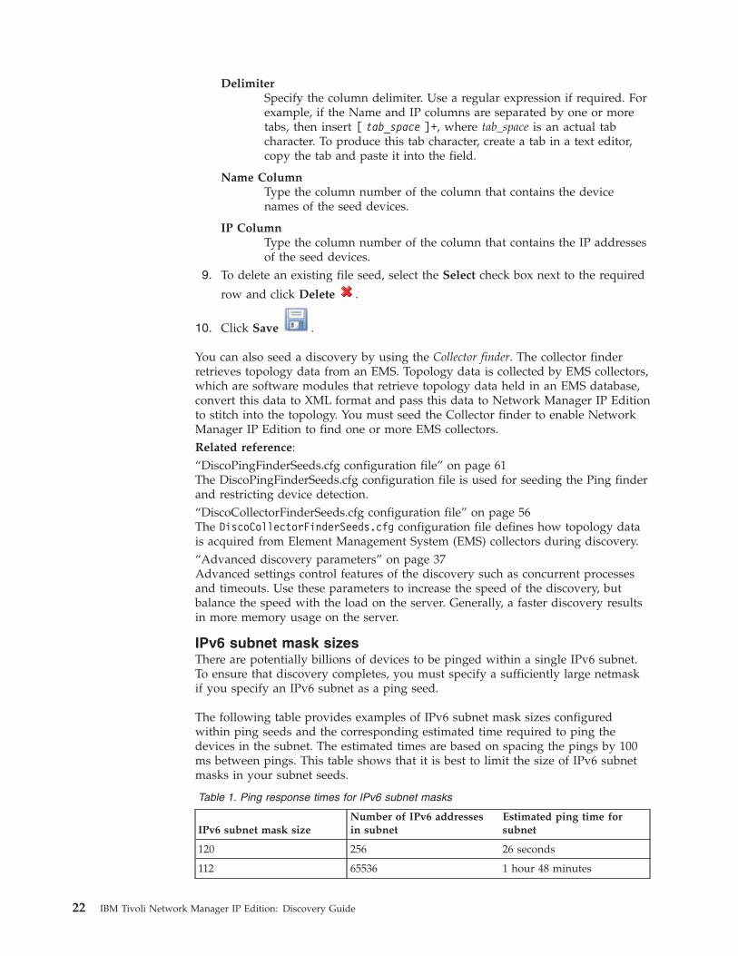
DelimiterSpecify the column delimiter. Use a regular expression if required. Forexample, if the Name and IP columns are separated by one or moretabs, then insert [ tab_space ]+, where tab_space is an actual tabcharacter. To produce this tab character, create a tab in a text editor,copy the tab and paste it into the field.
Name ColumnType the column number of the column that contains the devicenames of the seed devices.
IP ColumnType the column number of the column that contains the IP addressesof the seed devices.
9. To delete an existing file seed, select the Select check box next to the required
row and click Delete .
10. Click Save .
You can also seed a discovery by using the Collector finder. The collector finderretrieves topology data from an EMS. Topology data is collected by EMS collectors,which are software modules that retrieve topology data held in an EMS database,convert this data to XML format and pass this data to Network Manager IP Editionto stitch into the topology. You must seed the Collector finder to enable NetworkManager IP Edition to find one or more EMS collectors.Related reference:“DiscoPingFinderSeeds.cfg configuration file” on page 61The DiscoPingFinderSeeds.cfg configuration file is used for seeding the Ping finderand restricting device detection.“DiscoCollectorFinderSeeds.cfg configuration file” on page 56The DiscoCollectorFinderSeeds.cfg configuration file defines how topology datais acquired from Element Management System (EMS) collectors during discovery.“Advanced discovery parameters” on page 37Advanced settings control features of the discovery such as concurrent processesand timeouts. Use these parameters to increase the speed of the discovery, butbalance the speed with the load on the server. Generally, a faster discovery resultsin more memory usage on the server.
IPv6 subnet mask sizesThere are potentially billions of devices to be pinged within a single IPv6 subnet.To ensure that discovery completes, you must specify a sufficiently large netmaskif you specify an IPv6 subnet as a ping seed.
The following table provides examples of IPv6 subnet mask sizes configuredwithin ping seeds and the corresponding estimated time required to ping thedevices in the subnet. The estimated times are based on spacing the pings by 100ms between pings. This table shows that it is best to limit the size of IPv6 subnetmasks in your subnet seeds.
Table 1. Ping response times for IPv6 subnet masks
IPv6 subnet mask sizeNumber of IPv6 addressesin subnet
Estimated ping time forsubnet
120 256 26 seconds
112 65536 1 hour 48 minutes
22 IBM Tivoli Network Manager IP Edition: Discovery Guide
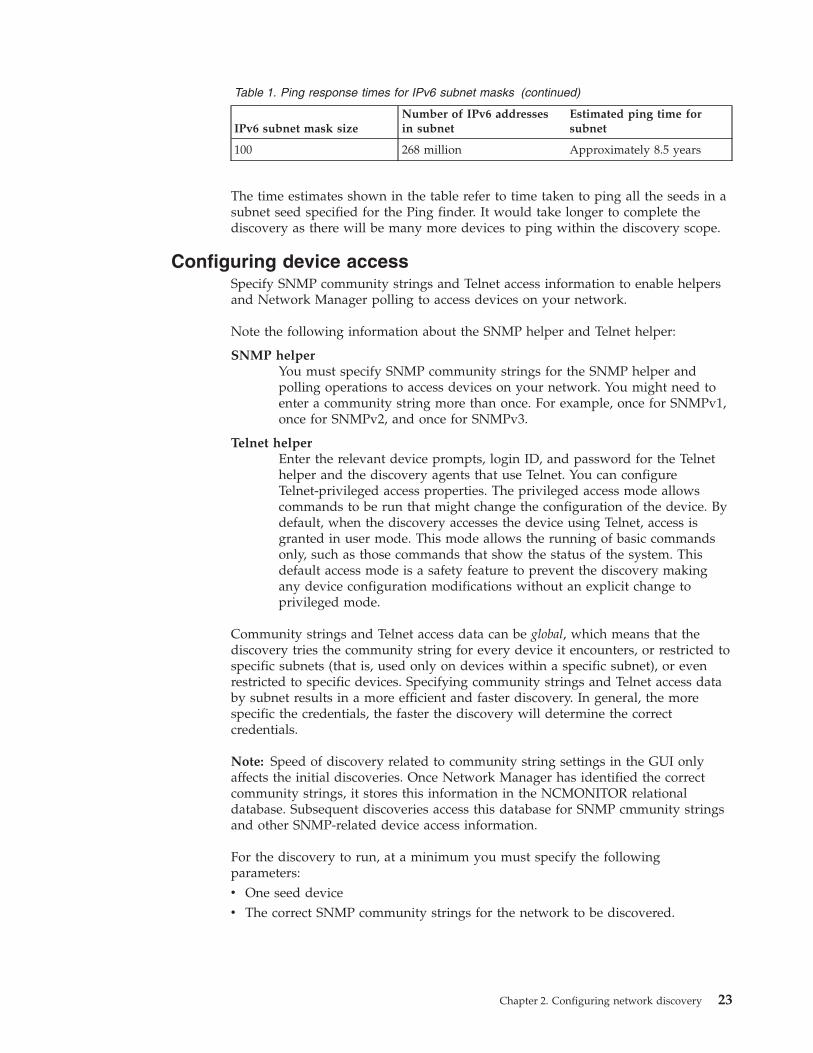
Table 1. Ping response times for IPv6 subnet masks (continued)
IPv6 subnet mask sizeNumber of IPv6 addressesin subnet
Estimated ping time forsubnet
100 268 million Approximately 8.5 years
The time estimates shown in the table refer to time taken to ping all the seeds in asubnet seed specified for the Ping finder. It would take longer to complete thediscovery as there will be many more devices to ping within the discovery scope.
Configuring device accessSpecify SNMP community strings and Telnet access information to enable helpersand Network Manager polling to access devices on your network.
Note the following information about the SNMP helper and Telnet helper:
SNMP helperYou must specify SNMP community strings for the SNMP helper andpolling operations to access devices on your network. You might need toenter a community string more than once. For example, once for SNMPv1,once for SNMPv2, and once for SNMPv3.
Telnet helperEnter the relevant device prompts, login ID, and password for the Telnethelper and the discovery agents that use Telnet. You can configureTelnet-privileged access properties. The privileged access mode allowscommands to be run that might change the configuration of the device. Bydefault, when the discovery accesses the device using Telnet, access isgranted in user mode. This mode allows the running of basic commandsonly, such as those commands that show the status of the system. Thisdefault access mode is a safety feature to prevent the discovery makingany device configuration modifications without an explicit change toprivileged mode.
Community strings and Telnet access data can be global, which means that thediscovery tries the community string for every device it encounters, or restricted tospecific subnets (that is, used only on devices within a specific subnet), or evenrestricted to specific devices. Specifying community strings and Telnet access databy subnet results in a more efficient and faster discovery. In general, the morespecific the credentials, the faster the discovery will determine the correctcredentials.
Note: Speed of discovery related to community string settings in the GUI onlyaffects the initial discoveries. Once Network Manager has identified the correctcommunity strings, it stores this information in the NCMONITOR relationaldatabase. Subsequent discoveries access this database for SNMP cmmunity stringsand other SNMP-related device access information.
For the discovery to run, at a minimum you must specify the followingparameters:v One seed devicev The correct SNMP community strings for the network to be discovered.
Chapter 2. Configuring network discovery 23
You can also configure the SNMP Helper to use the GetBulk operation whenSNMP v2 or v3 is used. Use of the GetBulk operation improves discovery speed.For more information, see the IBM Tivoli Network Manager IP Edition Installation andConfiguration Guide.
When discovering devices using SNMPv3, the Cisco switches must have the VLANcontext added to the view group for each VLAN.
To configure device access:1. Click Discovery > Network Discovery Configuration. From the Domain list,
select the required domain.2. Click Passwords.
3. To add a new SNMP community string, click New . The SNMP PasswordProperties page is displayed.
4. Complete the fields as follows and then click OK:
Community StringType a name. When you save the community string, the name isencrypted, but on the GUI, the value is always displayedunencrypted. For speed of discovery, order the SNMP strings byfrequency, with the most common strings first.
Restriction: It is best practice not to use the at symbol (@) incommunity strings. Using this symbol in a community string cancause problems connecting to devices at discovery time.
Apply toThe discovery completes more quickly if you specify the correct scopeof the community strings. Select one of the following options:
All DevicesSelect this option if the community string is global.
IP AddressSelect this option if the community string is specific to an IPaddress, and type the IP address.
SubnetSelect this option if the community string is specific to asubnet. Type the required subnet and specify the number ofnetmask bits. The Netmask field is automatically updated.
SNMP VersionSpecify the version of SNMP for this SNMP community. If you specifySNMP V3, complete the following additional fields:
Security NameType a name.
Level Specify the required level of authentication and privacy.
NoAuthNoPriv,Select this option for SNMP communities that have noauthentication or private key. In this case there is noneed to specify any passwords.
AuthNoPrivSelect this option for SNMP communities that have an
24 IBM Tivoli Network Manager IP Edition: Discovery Guide
authentication key but no private key. Then specify apassword in the Auth Password field.
AuthPrivSelect this option for SNMP communities that haveboth an authentication and a private key. Then specifypasswords in the Auth Password and PrivatePassword fields.
Auth TypeSpecify the type of encryption for the authenticationpassword.
Restriction: The MD5 encryption option is not available ifyou are running a FIPS 140–2 installation of NetworkManager.
Priv TypeSpecify the type of encryption for the privacy password.
Restriction: The DES encryption option is not available if youare running a FIPS 140–2 installation of Network Manager.
SNMP PortSpecify the required port.
TimeoutSpecify the time in milliseconds to wait for a reply before timing out.
RetriesSpecify how many times you want the SNMP helper and pollingoperations to attempt to access a device.
5. Click Move Up and Move Down to arrange the SNMPcommunity strings. Put the most frequently used strings at the top of the list.
6. Click Save.
7. To add Telnet access information, click New. The Telnet PasswordProperties page is displayed.
8. Complete the fields as follows:
Apply toSelect one of the following options:
All devicesSelect this option if the data applies globally.
IP addressSelect this option if the string is specific to a device, and typethe IP address of the device.
SubnetSelect this option if the string is specific to a subnet. Type therequired subnet and specify the number of netmask bits. TheNetmask field is automatically updated.
Username promptType the prompt that you want to be displayed at login. If you do notknow the exact format of the prompt. use a regular expression.
UsernameType the user name.
Chapter 2. Configuring network discovery 25
Password promptType the prompt that you want to be displayed when the password isrequired at login. If you do not know the exact format of the prompt,use a regular expression.
PasswordType the password.
Console promptType the prompt that is displayed when you log in. If you do notknow the exact format of the prompt, use a regular expression.
Access portSpecify the port on which the Telnet helper and discovery agentsattempt to access devices.
TimeoutSpecify the time in milliseconds to wait for a reply before timing out.
Use SSHSelect this option to configure the Telnet Helper to use the SecureShell (SSH) program.
9. Optional: To configure Telnet-privileged access mode properties:a. Click Advanced. The Telnet Privileged Access Mode Properties page is
displayed.b. Complete the fields as follows and then click OK:
CommandType the command required to enter Telnet-privileged accessmode. This command is typically enable.
Password PromptType the prompt that you want to be displayed when thepassword is required at login. If you do not know the exact formatof the prompt, use a regular expression.
PasswordType the required password for privileged mode.
Console PromptType the prompt that is displayed when you log in. If you do notknow the exact format of the prompt, use a regular expression.
Commands requiring mode:Specify the commands that you want to make accessible fromprivileged mode. To add new commands, click New... and type thecommand in the Priv command field. The following commandsare required to run in enable mode:v show run
v show mac-address-table
v show ip nat translation
10. Click OK. Click Save .
When you save the Telnet password settings, the following passwords areautomatically encrypted:v Telnet passwordv Telnet privileged mode password (if specified)
26 IBM Tivoli Network Manager IP Edition: Discovery Guide
When you save the password settings, the following passwords are automaticallyencrypted:v SNMP community stringv SNMP authentication passwordv SNMP private password
If required, change the SNMP and Telnet encryption settings. For example, you canchange the encryption key file, or switch off encryption.Related tasks:“Enabling the StandardMPLSTE agent” on page 112To discover MPLS TE tunnels, you must enable the StandardMPLSTE agent andadd the relevant SNMP community strings.Related reference:“Advanced discovery parameters” on page 37Advanced settings control features of the discovery such as concurrent processesand timeouts. Use these parameters to increase the speed of the discovery, butbalance the speed with the load on the server. Generally, a faster discovery resultsin more memory usage on the server.“Connectivity at the layer 3 network layer” on page 316There are a number of discovery agents that retrieve connectivity information fromOSI model layer 3 (the Network Layer). Layer 3 is responsible for routing,congestion control, and sending messages between networks.
Activating agentsYou must enable the appropriate agents for the discovery you want to perform.You can specify agents for a full discovery or for a partial discovery.
You can speed up the time taken for a partial discovery by selecting only thoseagents essential to discover the new or modified devices. You might want to run apartial discovery if you know that new devices have been added to the network orthat engineers have been working on a device and have added or removedcomponents of this device.
Note: The more agents you run, the more data is retrieved from the network, andthe slower the discovery.
To activate agents:1. Click Discovery > Network Discovery Configuration. From the Domain list,
select the required domain.2. Click one of the following tabs, based on your requirements:
Tab Description
Full Discovery Agents Select agents from this tab to run a fulldiscovery.
Partial Discovery Agents Select agents from this tab to run a partialdiscovery.Note: The Reset button in the PartialDiscovery Agents window sets the partialagents to match the settings defined in theFull Discovery Agents window.
The Agents List is displayed, showing all available discovery agents for theselected discovery option.
Chapter 2. Configuring network discovery 27
3. Select the check boxes next to the required agents. For descriptions of theagents, select an agent name.To select all agents required for a layer 3 discovery, select the Layer 3 checkbox.To select all agents required for a layers 2 and 3 discovery, select the Full Layer2 and Layer 3 Discovery checkbox.
4. Click Save . If you have selected a invalid combination of agents, or acombination that might result in an inefficient discovery, a warning isdisplayed.
5. If applicable, follow the steps displayed in the warning:v If you selected an agent that must be run in conjunction with another agent
or agents, the warning indicates that the additional agents will be selected asapplicable. Click OK to select the agents, or click Cancel.
v If you selected an agent that cannot be run in conjunction with another agentor agents, the warning indicates that the redundant agents will beautomatically deselected. Click OK to deselect the recommended agent orclick Cancel.
Related tasks:“Enabling collector discovery agents” on page 101By default, the collector discovery agents are not enabled. You must enable theseagents if you are running a discovery that includes collector-based discovery.“Configuring MPLS agents” on page 105As part of MPLS discovery configuration you must enable one or more MPLSagents. You can also resolve the problem of duplicate IP addresses in differentVirtual Private Networks (VPNs) by configuring the AsAgent agent.Related reference:Appendix C, “Discovery agents,” on page 303Use this information to support the selection of discovery agents to run as part ofyour discovery.
Setting discovery filtersUse filters to filter out devices either before discovery or after discovery. You canfilter out devices based on a variety of criteria, including location, technology, andmanufacturer. Filters provide additional restrictions to those defined in the scopezones.
A filter is made up of one or more filter conditions. Filter conditions are defined inObject Query Language (OQL). You can add the following types of filter:
Prediscovery filtersPrediscovery filters prevent discovered devices from being polled forconnectivity information.
Post discovery filtersPost-discovery filters prevent discovered devices from being passed toMODEL.
Note: To ensure that alerts are not raised for interfaces that are excludedby the post discovery filter, you must set theRaiseAlertsForUnknownInterfaces variable. To this, perform the followingsteps:1. Edit the $NCHOME/etc/precision/NcPollerSchema.cfg configuration file.2. Add the following line to the file:
28 IBM Tivoli Network Manager IP Edition: Discovery Guide
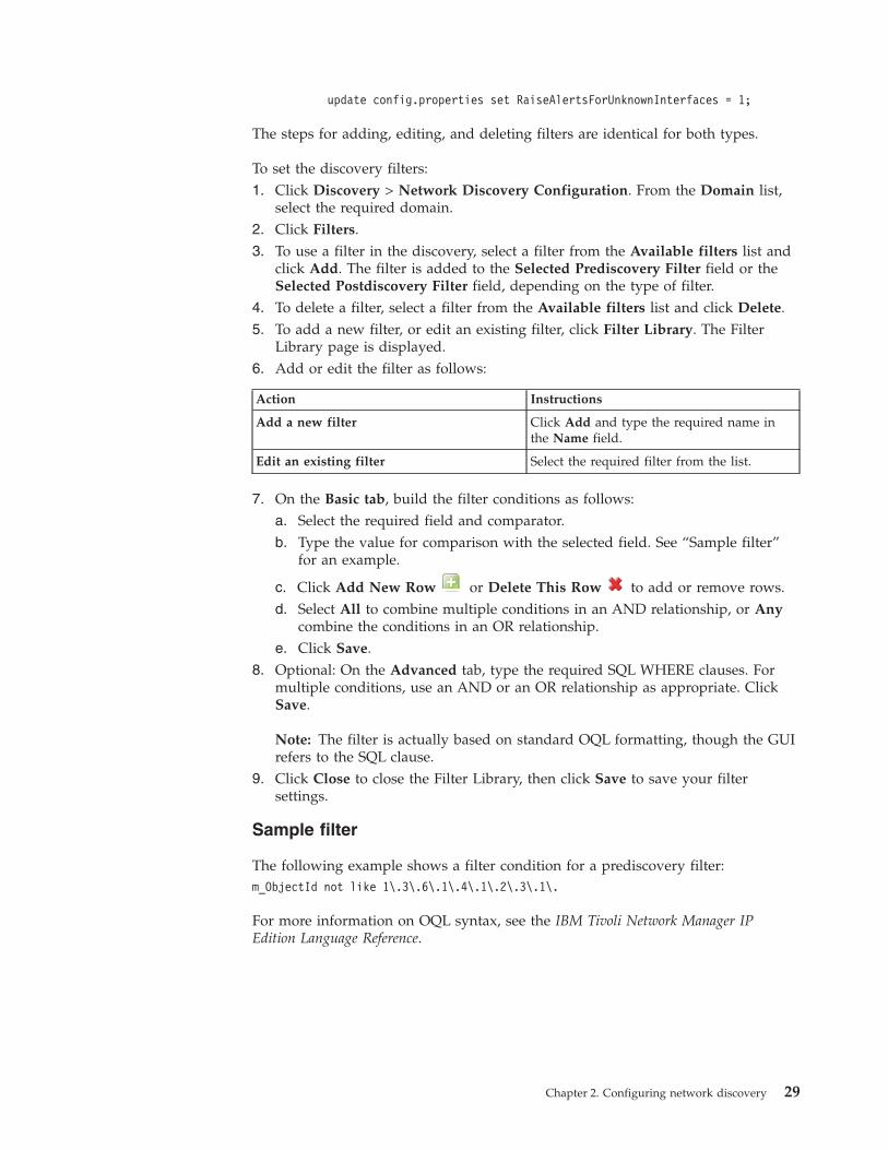
update config.properties set RaiseAlertsForUnknownInterfaces = 1;
The steps for adding, editing, and deleting filters are identical for both types.
To set the discovery filters:1. Click Discovery > Network Discovery Configuration. From the Domain list,
select the required domain.2. Click Filters.3. To use a filter in the discovery, select a filter from the Available filters list and
click Add. The filter is added to the Selected Prediscovery Filter field or theSelected Postdiscovery Filter field, depending on the type of filter.
4. To delete a filter, select a filter from the Available filters list and click Delete.5. To add a new filter, or edit an existing filter, click Filter Library. The Filter
Library page is displayed.6. Add or edit the filter as follows:
Action Instructions
Add a new filter Click Add and type the required name inthe Name field.
Edit an existing filter Select the required filter from the list.
7. On the Basic tab, build the filter conditions as follows:a. Select the required field and comparator.b. Type the value for comparison with the selected field. See “Sample filter”
for an example.
c. Click Add New Row or Delete This Row to add or remove rows.d. Select All to combine multiple conditions in an AND relationship, or Any
combine the conditions in an OR relationship.e. Click Save.
8. Optional: On the Advanced tab, type the required SQL WHERE clauses. Formultiple conditions, use an AND or an OR relationship as appropriate. ClickSave.
Note: The filter is actually based on standard OQL formatting, though the GUIrefers to the SQL clause.
9. Click Close to close the Filter Library, then click Save to save your filtersettings.
Sample filter
The following example shows a filter condition for a prediscovery filter:m_ObjectId not like 1\.3\.6\.1\.4\.1\.2\.3\.1\.
For more information on OQL syntax, see the IBM Tivoli Network Manager IPEdition Language Reference.
Chapter 2. Configuring network discovery 29
Related concepts:“Filters” on page 5Use prediscovery filters to increase the efficiency of discovery and post-discoveryfilters to prevent instantiation of devices.Related tasks:“Troubleshooting missing devices” on page 167If a device that you expect to find in your network topology is not present, followthese steps to troubleshoot the problem.Related reference:“Main discovery stitchers” on page 341This topic lists all discovery stitchers.Appendix A, “Discovery databases,” on page 183There are various specialized databases that are used by ncp_disco, the componentthat discovers network device existence and connectivity, and by ncp_model, thecomponent that manages, stores, and distributes the discovered network topology.“scratchTopology database schema” on page 263The scratchTopology database is defined in $NCHOME/etc/precision/DiscoSchema.cfg. Its fully qualified database table name is:scratchTopology.entityByName.
Available filter valuesUse this reference information to familiarize yourself with the permissible valueswhen you set discovery filters on the Network Discovery Configuration page.
Prediscovery filter values
When constructing a prediscovery filter, you can filter based on any of the fields inthe Details.returns table. These fields are as follows:
m_Name
m_UniqueAddress
m_Protocol
m_ObjectId
m_Description
m_HaveAccess
m_UpdAgent
m_AddressSpace
In addition, by using the Advanced tab, you can construct filter rows using any ofthe fields from within the m_ExtraInfo field.
Postdiscovery filter values
When constructing a post-discovery filter, you can filter based on any of the fieldsin the scratchTopology.entityByName table. These fields are as follows:
EntityNameThe unique name of a network entity.
AddressA list that contains an address for the object for layers 1-7 of the OSI model.
30 IBM Tivoli Network Manager IP Edition: Discovery Guide
DescriptionThe sysDescr or other description.
EntityTypeThe type of the entity.
EntityOIDThe class of the device.
StatusThe status of the entity.
IsActiveWhether the entity is active.
ContainsThe entities or other containers that are contained by this entity.
UpwardConnectionsThe entities that this entity is physically a part of.
RelatedToThe devices an entity is connected to.
ExtraInfoMiscellaneous extra information.
In addition, by using the Advanced tab, you can construct filter rows using any ofthe fields from within the ExtraInfo field.
Configuring Domain Name SystemYou can specify the methods that the Domain Name System (DNS) Helpers use toperform domain name lookups.
Helpers are specialized applications that retrieve information from and aboutnetwork devices for the discovery agents.
Each of method that you specify uses one of the following three domain methods:
DNS ServerA server on the network that is dedicated to performing domain nameresolution.
File The name of a file held on the Network Manager host that contains IPaddresses and host names in lookup table format.
SystemThe local DNS system on the Network Manager host.
Tip: You can define as many methods as is necessary. You can change the order inwhich these methods are retrieved by the DNS Helper so that the most commonlyaccessed method is retrieved first. This enables a more effective use of resourcesduring the discovery.
To configure DNSs:1. Click Discovery > Network Discovery Configuration. From the Domain list,
select the required domain.2. Click the DNS tab.3. Add a new DNS helper, or edit an existing helper as follows:
Chapter 2. Configuring network discovery 31
v To add a new DNS helper, click New .v To edit an existing helper, click the name of the required helper.
The DNS Service Properties page is displayed.4. Complete the fields as follows and then click OK.
Service NameType the name of the method.
Type Select one of the following options:
DNS ServerType the IP address of the required DNS server. In the Timeoutfield, specify the number of seconds to wait for a response fromthe DNS Server before timing out.
File Type the name of the file that contains the domain lookupinformation. Specify the order in which this informationappears in the lookup table by selecting one of the radiobuttons:v Name then IP
v IP then Name
SystemChoose this option to use the local DNS system on the NetworkManager server.
Domain SuffixSpecify the suffix to append to each device name after the name islooked up. The specified domain suffix is only added if no domainsuffix is present in the device name.
Note: If you expect the discovery to return some or all devices nameswith domain suffixes already appended, then you can specify a list ofexpected domain suffixes. The domain suffix value specified in theDomain Suffix field is not appended to any device names returned bythe discovery with these expected suffixes. To specify a list of expecteddomain suffixes, you must configure the DiscoDNSHelperSchema.cfgconfiguration file from the command line.
5. Repeat steps 3 on page 31 to 4 to add or edit the required methods.
6. In the Move column, click Move Up and Move Down to arrangethe methods in the order of most frequently-expected use, with the mostfrequently-used methods at the top.
7. Click Save .Related reference:“Advanced discovery parameters” on page 37Advanced settings control features of the discovery such as concurrent processesand timeouts. Use these parameters to increase the speed of the discovery, butbalance the speed with the load on the server. Generally, a faster discovery resultsin more memory usage on the server.“DiscoDNSHelperSchema.cfg configuration file” on page 56The DiscoDNSHelperSchema.cfg configuration file defines access to DNS, whichenables the discovery to do domain name lookups, by configuring the DNS helper.
32 IBM Tivoli Network Manager IP Edition: Discovery Guide
Configuring NAT translationTo configure NAT translation to discover NAT environments, map theaddress-space identifier for a NAT domain to the IP address of the associated NATgateway device.
After activating NAT, you must map the discovery scope zones to the NATaddress spaces. You do this on the Scope tab.
To configure NAT gateways:1. Click Discovery > Network Discovery Configuration. From the Domain list,
select the required domain.2. Click NAT.3. Add a new NAT gateway, or edit an existing gateway:
v To add a new NAT gateway, click New .v To edit an existing NAT gateway, click the IP address in the required row.
The NAT Gateway page is displayed.4. Complete the fields as follows and click OK:
IP AddressType the public IP address of the NAT gateway device.
Address SpaceType the address space identifier that you want to use for theassociated NAT domain.
5. Click Save .6. To activate NAT translation for the discovery, select Enable Network Address
Translation (NAT) Support. Click Save and then map the discovery scopezones to the NAT address spaces:a. Click Scope.b. Click a scope zone to edit it. The Scope Properties page is displayed.c. In the Address Space field, enter the NAT address space and click OK. The
Address Space field appears on the Scope Properties only after the EnableNetwork Address Translation (NAT) Support has been selected.
d. Repeat the previous two steps for all the required scope zones.
e. Click Save .
NAT Address Spaces Dynamic Distinct view is created automatically if EnableNetwork Address Translation (NAT) Support is turned on. Once discovery iscomplete, use the Network Views to visualize the NAT Address Spacesnetwork view.
Chapter 2. Configuring network discovery 33
Related tasks:“Scoping discovery” on page 17To scope the discovery, define the zones of the network (that is, subnet ranges) thatyou want to include in the discovery, and the zones that you want to exclude.“Configuring NAT discoveries” on page 115Configure a Network Address Translation (NAT) discovery to discover NATenvironments, by mapping the address-space identifier for a NAT domain to the IPaddress of the associated NAT gateway device.Related reference:“Quick reference for NAT discovery configuration” on page 118Use this information as a step-by-step guide to configuring a NAT discovery..
Configuring a multicast discoveryConfigure a multicast discovery by enabling the required agents and scoping thediscovery.Related concepts:“Types of scoping” on page 3Network Manager offers several types of scoping.Related tasks:“Scoping discovery” on page 17To scope the discovery, define the zones of the network (that is, subnet ranges) thatyou want to include in the discovery, and the zones that you want to exclude.Related reference:“scope.multicastSource table” on page 205The scope.multicastSource table defines which IPM routes to discover. This isparticularly useful if you have multiple IPM route sources, since you can scopemulticast discovery by IPM route source to focus on the sources of interest.“scope.multicastGroup table” on page 204The scope.multicastGroup table defines which multicast groups to discover andwhich details to retrieve from these groups.
Enabling the multicast agentsTo discover multicast groups, you must enable the appropriate agents and add therelevant SNMP community strings.
To enable the agents, complete the following steps.1. Click Discovery > Network Discovery Configuration. From the Domain list,
select the required domain.2. Click the Full Discovery Agents tab. The Agents List is displayed, showing all
available discovery agents for the selected discovery option.3. Click Full Layer 2 and Layer 3 Discovery > Multicast.4. Select the check box next to the agents you want to enable.
a. Enable the StandardPIM agent to discover protocol-independent multicastgroups compliant with the RFC2934 PIM MIB.
b. Enable the StandardIPMRoute agent to discover IP multicasting networkscompliant with the RFC2932 IPMRoute MIB.
c. Enable the StandardIGMP agent to discover multicast groups running theInternet Group Membership Protocol (IGMP).
5. Click Save .
34 IBM Tivoli Network Manager IP Edition: Discovery Guide
6. Optional: If you want to rediscover multicast groups, also enable theappropriate agents for partial discoveries.
7. Ensure that the SNMP community strings are configured correctly to access thedevices in the multicast groups.
Related reference:“Multicast agents” on page 323Multicast agents retrieve data from devices participating in multicast groups androutes.
Scoping a multicast discoveryConfigure which multicast groups and sources to discover using the Multicast tab.
To configure a multicast discovery, complete the following steps.1. Click Discovery > Network Discovery Configuration. From the Domain list,
select the required domain.2. Click Multicast.3. In the Multicast Groups section, create a new multicast group or edit an
existing group:
v To create a new group to discover, click New .v To edit an existing group, click the group name.
The Multicast Group Properties page is displayed.4. Define the scope properties using the following fields:
Group NameSpecify a name for this multicast group.
PIM ModeSelect whether to include or exclude Protocol Independent Multicast(PIM) data from the discovery. By default, PIM data is included.
IPM Route ModeSelect whether to include or exclude Internet Protocol Multicast (IPM)group data from the discovery. By default, IPM Group data isincluded.
IGMP ModeSelect whether to include or exclude Internet Group ManagementProtocol (IGMP) data from the discovery. By default, IGMP data isincluded.
ProtocolOnly IPv4 is supported.
Specify which Group subnets to add to Multicast GroupsUse the following fields and buttons to add and delete group subnets:
SubnetEnter a subnet and netmask for a group subnet to add to themulticast groups.
Add Click Add the add this group.
Delete Select a group subnet from the adjacent list and click Deleteto delete the selected group.
Note: Reserved multicast addresses are excluded from the scope by default.5. Click OK.
Chapter 2. Configuring network discovery 35
6. To delete one or more groups, select the groups you want to delete and click
the Delete button . To select or deselect all groups, click the Select All
or Deselect All button.7. In the Multicast Sources section, create a new multicast source or edit an
existing source.
v To create a new source to discover, click New .v To edit an existing source, click the source name.
The Multicast Source Properties page is displayed.8. Define the source properties using the following fields:
IPM Route ModeSelect whether to include or exclude the group:v Unknown - use default
v Include source
v Exclude source
ProtocolOnly IPv4 is supported.
Specify which Group subnets to add to Multicast SourcesUse the following fields and buttons to add and delete group subnets:
SubnetEnter a subnet and netmask for a group subnet to add to themulticast sources.
Add Click Add the add this group.
Delete Select a group subnet from the adjacent list and click Deleteto delete the selected group.
Specify which Source subnets to add to Multicast SourcesUse the following fields and buttons to add and delete group subnets:
SubnetEnter a subnet and netmask for a sources subnet to add to themulticast sources.
Add Click Add the add this group.
Delete Select a source subnet from the adjacent list and click Deleteto delete the selected soource.
9. Click OK.10. To delete one or more groups, select the groups you want to delete and click
the Delete button . To select or deselect all groups, click the Select All
or Deselect All button.
11. Click Save .
36 IBM Tivoli Network Manager IP Edition: Discovery Guide
Advanced discovery parametersAdvanced settings control features of the discovery such as concurrent processesand timeouts. Use these parameters to increase the speed of the discovery, butbalance the speed with the load on the server. Generally, a faster discovery resultsin more memory usage on the server.
Set the advanced parameters on the Advanced tab of the Network Discovery
Configuration page. After you have set the advanced parameters, click Save .
Attention: Modify the advanced settings only if you are an experienced NetworkManager user. If you modify the advanced parameters and the discovery does notwork as expected, click Reset to restore the default settings.
“Advanced Finder Configuration”“Advanced Ping Finder Configuration”“Advanced Discovery Configuration” on page 39“Advanced Telnet Helper Configuration” on page 38“Advanced SNMP Helper Configuration” on page 38“Advanced DNS Helper Configuration” on page 39“Advanced Discovery Configuration” on page 39
Advanced Finder Configuration
To set advanced parameters for the File finder, use the following field:
Concurrent File FindersSpecify the number of threads to be used by the File finder. Each threadcan process a different seed file simultaneously. If you have many seedfiles and spare resources on the discovery server, more threads might resultin a faster discovery. If you have only one seed file, increasing the numberof threads has no effect.
Advanced Ping Finder Configuration
To set the advanced parameters for the Ping finder, use the following fields:
Concurrent Ping FindersSpecify the number of threads to be used by the Ping finder. Each threadprocesses one pingFinder.pingRules insert at a time. Increasing the numberof threads does not speed up a single large ping sweep but might speedup feedback of many addresses. However, you must balance speed againstthe resources of your machine and the ability of the ping receiver toprocess the ping responses in a timely manner. If the number of threads istoo high, the ping receiver will fall behind, resulting in false ping failuresand a loss of device discovery.
Studies have shown that the default number of 10 threads is optimal formost situations. You can gradually increase the number of threads andmonitor the number of ping failures and make a note of time savings.Depending on the resources available, at a certain point the benefits startto decrease as resources are overloaded.
Default TimeoutSpecify the maximum time, in milliseconds, to wait for a reply from apinged address. If you know that network latency is low, a reduced wait
Chapter 2. Configuring network discovery 37
time might result in a faster discovery. A value that is too low for yournetwork might result in devices not being discovered.
Default Number of RetriesSpecify the number of times a device is to be pinged again following afailed initial ping.
Inter-Ping TimeSpecify the interval in milliseconds between ping attempts made againstthe devices contained in a list or subnet. If network traffic resulting fromthe discovery is not an issue, this value can be reduced.
Allow Broadcast PingingTo enable broadcast address pinging, select this check box.
Allow Multicast PingingTo enable multicast address pinging, select this check box.
Advanced Telnet Helper Configuration
To set advanced parameters for the Telnet helper, use the following fields:
Concurrent Telnet HelpersSpecify the number of threads to be used by the Telnet helper. If you havemany devices from which you want to access data using Telnet or SSHthen increasing this value might result in a faster discovery. Typicalexamples of such devices are Catalyst switches, MPLS devices, and NATgateways. If you change this value, be sure that your system is configuredto allow at least this number of concurrent Telnet sessions.
Default TimeoutSpecify the maximum time, in milliseconds, to wait for access to a device.
Number of RetriesSpecify the number of times to try to connect to the device following afailed initial connection attempt.
Tip: You can also configure some other advanced settings in theDiscoTelnetHelperSchema.cfg file.
Advanced SNMP Helper Configuration
To advanced parameters for the SNMP helper, use the following fields:
Concurrent SNMP HelpersSpecify the number of threads to be used by the helper. If you have manydevices with SNMP access and spare resources on the discovery server,more threads might result in a faster discovery. If you change this value,make sure that your system is configured to allow at least this number ofconcurrent SNMP sessions. This value must be more than the number ofthreads used by the Details discovery agent.
TimeoutSpecify the maximum time, milliseconds, to wait for access to a device.
Number of RetriesSpecify the number of attempts to retrieve one or more SNMP variablesfrom a device after a failed initial attempt.
GetNext SlowdownSpecify the delay, in milliseconds, between each SNMP GetNext request.
38 IBM Tivoli Network Manager IP Edition: Discovery Guide
The m_GetNextSlowDown parameter is applied when the number of separateGetNext requests issued in order to retrieve a non-scalar SNMP variableexceeds the value of the m_GetNextBoundary parameter.
GetNext BoundarySpecify the minimum number of GetNext requests to be issued when anon-scalar SNMP variable is retrieved from a device. Them_GetNextBoundary parameter is applied before the delay specified by them_GetNextSlowDown parameter is introduced.
Advanced DNS Helper Configuration
To set advanced parameters for the DNS helper, use the following fields:
Concurrent DNS HelpersSpecify the number of threads to be used by the helper. If you change thisvalue, be sure that your system is configured to allow at least this numberof concurrent DNS sessions.
Default TimeoutSpecify the maximum time, in milliseconds, to wait for a response from adevice.
Advanced Discovery Configuration
To specify advanced feedback control, ping verification, and further advanceddiscovery parameters, use the following fields:
Enable Feedback ControlSpecify whether to enable feedback control. Feedback means that the datareturned by agents is used by the discovery to find other devices.Examples of feedback data include the IP addresses of remote neighbors,and addresses in the subnet within which a local neighbor exists.
No FeedbackFeedback is switched off for all discoveries and rediscoveries. Onlythe devices specified to the finders are discovered. This optionmeans that discoveries and rediscoveries complete in the quickestpossible time. However, the resulting network topology isincomplete unless you specify all devices that you want to discoveras seeds.
Tip: Switch feedback off if you want to discover only a list ofcertain devices. Specify the devices you want to discover as seeds.
FeedbackFeedback is switched on for full discoveries, full rediscoveries, andpartial rediscoveries. This option provides a complete topology inall situations but takes the longest.
Feedback Only on FullThis setting is on by default. Feedback is switched on for fulldiscoveries and full rediscoveries, but switched off for partialrediscoveries.
Enabling Ping VerificationSpecify whether the discovery checks for pingable interfaces. If a device isnot pingable, the device is not polled for alerts.
Chapter 2. Configuring network discovery 39
Don't Check PingabilityNone of the discovered interfaces are checked for whether they canbe pinged. Interfaces are polled regardless of whether they arepingable at discovery.
Check PingabilityAfter discovery, every discovered interface is checked for whetherthey can be pinged. The check is run against the details.returnstable. Interfaces that have an entry in this table are pingable.Interfaces that do not have an entry in this table are not pingable.The pingable interfaces are marked to be polled.
Detect Best SettingThis setting is on by default. If feedback control has been enabled,after discovery, every discovered interface is checked for whetherthey can be pinged. The check is run against the details.returnstable. Interfaces that have an entry in this table are pingable.Interfaces that do not have an entry in this table are not pingable.The pingable interfaces are marked to be polled.
Restriction: This option works only when you select one of thefollowing options from the Enable Feedback Control list: Feedbackor Feedback only on Full.
Enable 'Allow Virtual'Specify how you want the discovery to handle virtual IP addresses: 1.
Don't Allow VirtualDoes not discover virtual IP addresses.
Allow VirtualDiscovers virtual IP addresses. This setting is on by default.
Allow if in scope.specialDiscovers virtual IP addresses only if the address is defined in thescope.special table. This table defines management IP addresses.
Enable VLAN ModellingEnable this setting to model VLANs in this discovery. If you enable VLANmodeling, then you can partition discovered topologies based on VLANmembership. Disabling VLAN modeling reduces discovery time.
Enable SysName NamingEnable this setting to name devices using the value of the SNMP sysNamevariable as the main source of naming information. The sysName variablemust be set and must be unique within the network. Enabling this settinghas no impact on the discovery time, because the sysName variable isretrieved by the Details agent by default.
Enable Caching of Discovery TablesEnable this setting to cache data during the discovery process in order toenable data recovery if the Discovery engine, ncp_disco, fails. A discovery
1. Devices are typically discovered using IP addresses retrieved by the AssocAddress agent. If a device is discovered using an IPaddress that was not retrieved by the AssocAddress agent, then the IP address is probably non-standard. This type of IP addressis called a virtual IP address. Examples of virtual IP addresses are HSRP and VRRP addresses, which are shared by multipledevices for fault tolerance. Other examples include certain management interfaces that might be on a single device but do notappear in the IP table for security reasons. Virtual IP addresses include management addresses. A management address is an IPaddress whose only role is to manage the device. Management addresses are often on a separate network isolated from thecustomer traffic. These addresses are defined in the scope.special table.
40 IBM Tivoli Network Manager IP Edition: Discovery Guide
running in this mode is slower than a standard discovery, because of theextra time required to store data on the disk throughout the discoveryprocess.
Enable File Finder VerificationEnable this setting to use the Ping finder to verify the existence of devicesspecified in the files used by the File finder. If you enable this setting,ensure that the Ping finder is enabled. Enable this setting if you are notsure that the devices are still connected to the network. For example, youmight want to enable this setting if your network is rapidly changing.
Enable Inference of Dumb HubsConfigure the discovery to infer the existence of an unmanaged hub if thediscovery finds a port that is connected to more than one item. Thediscovery then connects that port to an unmanaged hub, and also connectsall the other port involved in the connection to the unmanaged hub. Thistype of discovery makes the topology much clearer. 2 By selecting thisoption, you instruct the discovery to activate the AddUnmanagedHubstitcher, which manages the inference of dumb hubs.
Enable Rediscovery Rebuild LayersEnable this setting to rebuild the topology layers following a partialrediscovery. If you specify that topology layers are rebuilt following partialrediscovery, the result is an accurate topology showing all connectivity.However, the process of adding new devices takes longer.
Tip: To configure a partial rediscovery to run as quickly as possible,disable this option.
Enable RT-Based MPLS VPN DiscoveryThis setting is relevant to MPLS discoveries. Enable this setting to displayprovider edge devices only (RT-based MPLS discovery).
Enable Rediscovery of Related DevicesBy default the remote neighbors of a device are not discovered, even ifrediscovery of that device indicates that the remote neighbors havechanged. The remote neighbors can be rediscovered on the next fullrediscovery. Enable this setting if you want to change this default behaviorand rediscover any changed remote neighbors when rediscovering thatdevice.
Tip: To configure a partial rediscovery to run as quickly as possible,disable this option.
Enable ifName/ifDescr Interface NamingChanges the default naming convention for discovered interfaces. Namesinterfaces using data from the SNMP interfaces table ifName and ifDescrfields as appropriate. For example, Fa0/0, Gi 1.0.2:0, Gigabit Ethernet4/1. If you change the default naming convention for discovered interfaces,you must change the BuildInterfaceName stitcher to specify your namingconvention.
2. For example, if port number 1 on switches A, B, C, and D are all connected to each other, then this discovery option inserts anunmanaged hub E into the topology. The discovery then connects port 1 on switch A to E, rather than to B. It similarly connectsport 1 on switches B, C, and D to E. A connection is created between device A and hub device E. Hub device E, and theconnections to this device, might not actually exist in reality.
Chapter 2. Configuring network discovery 41
Tip: Some devices might report interface names and descriptions that aretoo long to display properly in the topology display. If there are devicesthat report long or incorrect interface names and descriptions, disable thissetting.
Enable Inference of PEs using BGP data on CEsDiscovers intervening provider networks as a “third-party” object onmultiple networks that run across a provider network. Examples of thistype of network include enterprise VPNs across a provider MPLS corenetwork. Select this option if you want to link all your networks in a singletopology and perform root cause analysis (RCA) across your networks.
This option infers the existence of inaccessible provider-edge (PE) devicesby using the BGP data on the customer-edge (CE) devices that point to thePE devices. In order to discover this BGP data, the BGP discovery agentsmust be enabled.
You can also optionally specify which of the inferred PE devices are validdevices, by populating the scope.inferMPLSPEs table, using standardformat scope entries, as in the scope.zones table. If populated this tableallows you to define which IP addresses you see on CE devices that youconsider valid PE devices. Use this option when you have inaccessibledevices that are connected by BGP but which are not actually PE devices.
Enable Inference of MPLS CE routers on /30 subnetsGenerates Service-Affected Events on customer VPNs. Select this option ifyou are a service provider without access to customer CE routers.
42 IBM Tivoli Network Manager IP Edition: Discovery Guide
Related concepts:“About Service Affected Events” on page 104A Service Affected Event (SAE) alert warns operators that a critical customerservice has been affected by one or more network events.“Option to rebuild topology layers” on page 301You can specify whether to rebuild the topology layers following a partialrediscovery. Using this option, you can increase the speed of partial rediscovery.Related tasks:“Configuring MPLS discovery method” on page 108You can configure MPLS discovery in either of two ways: Route Target (RT)-baseddiscovery; Label Switched Path (LSP)-based discovery.“Inferring the existence of CE routers” on page 109You can infer the existence of your customers’ CE routers by making specificationsin the advanced discovery configuration options within the DiscoveryConfiguration GUI.Related reference:“Main discovery stitchers” on page 341This topic lists all discovery stitchers.“Failover database” on page 270Failover recovery with the failover database is not to be confused with agent andfinder failover recovery, which are configured directly from the disco.config table.When selected, agent and finder failover recovery operate regardless of whetherrecovery with the failover database is implemented.“disco.config table” on page 183The config table configures the general operation of the discovery process.“inferMPLSPEs table” on page 202Use the inferMPLSPEs table when enabling inference of inaccessible provider-edge(PE) devices by using the BGP data on the customer-edge (CE) devices. This tableenables you to optionally specify which zones to process to determine which of theinferred PE devices are valid devices.
Starting a discoveryAfter you configure a discovery, you can start and, if necessary, stop the discovery.
Make any required discovery configuration changes before you launch thediscovery.
You can start the following types of discovery:
DiscoveryRun a full discovery to discover your network for the first time, or torefresh the network topology if you know the network has changed.
Partial discoveryRun a partial discovery if you know that the changes to your network arelimited to a small number of devices. You need to configure scoping andseeding as part of starting each partial discovery. If the relationship of thedevices that are in scope with their neighboring devices has changed, thenthe neighboring devices may also be discovered. If the partial discoveryneeds to discover a large amount of devices based on connectivityinformation, then a full discovery is started.
Note: If you stop a running discovery, you must then do a full discovery beforeyou are able to do a partial discovery.
Chapter 2. Configuring network discovery 43
To start a discovery, complete the following steps.1. Click Discovery > Network Discovery Status.2. Select the domain in which you want to run a discovery from the Domain
menu. You can start to type the name of the domain, and matching domainsare listed below the Domain field.
3. Start a full or partial discovery:
v To start a full discovery, click Start Discovery only. The discoverystarts.
Important: In Network Manager V3.9 there is no longer any need to pressStop Discovery and then Start Discovery in order to pick up discoveryconfiguration changes. Network Manager picks up any saved discovery
configuration changes when you click Start Discovery .v To start a partial discovery, click the downward-facing arrow next to the
Start Discovery button and select Start Partial Discovery from themenu (if a full discovery has not been run since the last time that thediscovery engine, ncp_disco, was started, the option to start a partialdiscovery is grayed out). The Partial Discovery window is displayed. Specifythe IP addresses and subnets that contain the devices to be discovered:
a. Under Partial Discovery, select the required nodes and subnets.b. To add a new subnet or node, click New.
c. Complete the fields as follows and click OK:
RediscoverSelect one of the following options:
IP AddressType the required IP address.
SubnetType the required subnet and specify the number ofnetmask bits. The Netmask field is automatically updated.
d. To add new scope zones, click Scope.
e. To add a new discovery scope zone click New . To edit an existingscope zone, click the required entry in the list.
f. Complete the fields as follows and click OK:
Scope By:Select one of the following options:
SubnetType the required subnet and specify the number of netmaskbits. The Netmask field is automatically updated.
You can specify a subnet or an individual IP address usingthese fields.v For example, to specify a Class C subnet 10.30.2.0, type
10.30.2.0/24, where 10.30.2.0 is the subnet prefix, and24 is the subnet mask.
44 IBM Tivoli Network Manager IP Edition: Discovery Guide
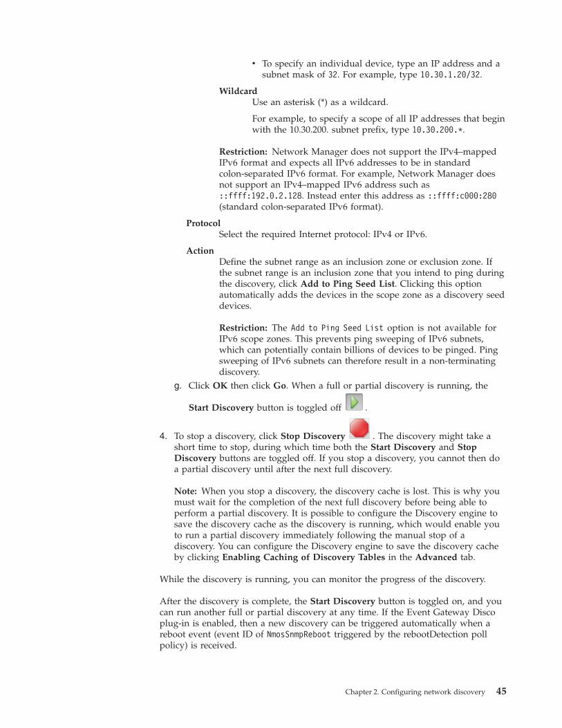
v To specify an individual device, type an IP address and asubnet mask of 32. For example, type 10.30.1.20/32.
WildcardUse an asterisk (*) as a wildcard.
For example, to specify a scope of all IP addresses that beginwith the 10.30.200. subnet prefix, type 10.30.200.*.
Restriction: Network Manager does not support the IPv4–mappedIPv6 format and expects all IPv6 addresses to be in standardcolon-separated IPv6 format. For example, Network Manager doesnot support an IPv4–mapped IPv6 address such as::ffff:192.0.2.128. Instead enter this address as ::ffff:c000:280(standard colon-separated IPv6 format).
ProtocolSelect the required Internet protocol: IPv4 or IPv6.
ActionDefine the subnet range as an inclusion zone or exclusion zone. Ifthe subnet range is an inclusion zone that you intend to ping duringthe discovery, click Add to Ping Seed List. Clicking this optionautomatically adds the devices in the scope zone as a discovery seeddevices.
Restriction: The Add to Ping Seed List option is not available forIPv6 scope zones. This prevents ping sweeping of IPv6 subnets,which can potentially contain billions of devices to be pinged. Pingsweeping of IPv6 subnets can therefore result in a non-terminatingdiscovery.
g. Click OK then click Go. When a full or partial discovery is running, the
Start Discovery button is toggled off .
4. To stop a discovery, click Stop Discovery . The discovery might take ashort time to stop, during which time both the Start Discovery and StopDiscovery buttons are toggled off. If you stop a discovery, you cannot then doa partial discovery until after the next full discovery.
Note: When you stop a discovery, the discovery cache is lost. This is why youmust wait for the completion of the next full discovery before being able toperform a partial discovery. It is possible to configure the Discovery engine tosave the discovery cache as the discovery is running, which would enable youto run a partial discovery immediately following the manual stop of adiscovery. You can configure the Discovery engine to save the discovery cacheby clicking Enabling Caching of Discovery Tables in the Advanced tab.
While the discovery is running, you can monitor the progress of the discovery.
After the discovery is complete, the Start Discovery button is toggled on, and youcan run another full or partial discovery at any time. If the Event Gateway Discoplug-in is enabled, then a new discovery can be triggered automatically when areboot event (event ID of NmosSnmpReboot triggered by the rebootDetection pollpolicy) is received.
Chapter 2. Configuring network discovery 45

Related concepts:“About types of discovery” on page 1Different terms are used to describe network discovery, depending on what isbeing discovered and how the discovery has been configured. You can rundiscoveries, rediscoveries, full and partial discoveries, and you can set upautomatic discovery.Related tasks:“Monitoring network discovery from the GUI” on page 131From the Active Discovery Status page, you can monitor the status and progress ofthe current discovery, investigate the work of the discovery agents, and viewdetails of the last discovery.“Starting partial discovery from the GUI” on page 158Starting a partial discovery involves defining a seed and scopes.“Troubleshooting an idle discovery” on page 168If you start the discovery, and after some minutes no devices have beendiscovered, follow these troubleshooting steps.
Schemas and tables for GUI discovery parametersUse this reference information to learn to which schemas and table the settingsmade on the tabs of the Network Discovery Configuration page are saved.
The following table describes the tables to which the settings made on each tab ofthe Network Discovery Configurationpage are saved. In these tables,DOMAIN_NAME represents the name of the network domains in yourdeployment, for example NCOMS.
Table 2. Schemas and tables to which the discovery parameters are mapped
NetworkDiscoveryConfigurationtab Description Schema or table name
Scope The zones of the network (that is, subnetranges) that you want to include in thediscovery, and the zones that you want toexclude.
DiscoScope.DOMAIN_NAME.cfg
Seed The location from which to begin discoveringdevices. This might be one or more IPaddresses, or subnet addresses. To seed thediscovery, the following finders are used: Pingfinder and File finder.
Ping finder:DiscoPingFinderSeeds.DOMAIN_NAME.cfg
File finder:DiscoFileFinderParseRules.DOMAIN_NAME.cfg
Full DiscoveryAgents andPartialRediscoveryAgents
The discovery agents to be used to investigatedevice connectivity. Default agents areprovided for the type of discovery you want toperform, for example a layer 2 or layer 3discovery. You can select different set of agentsfor full discoveries and for partial discoveries.The agents vary because connectivityinformation varies with the technology of thehardware in the network.
DiscoAgents.DOMAIN_NAME.cfg
Device Access SNMP community strings and Telnetparameters that Network Manager uses tointerrogate devices that use SNMP and Telnet.
SNMP community strings:SnmpStackSecurityInfo.cfg
Telnet access: TelnetStackPasswords.cfg
46 IBM Tivoli Network Manager IP Edition: Discovery Guide
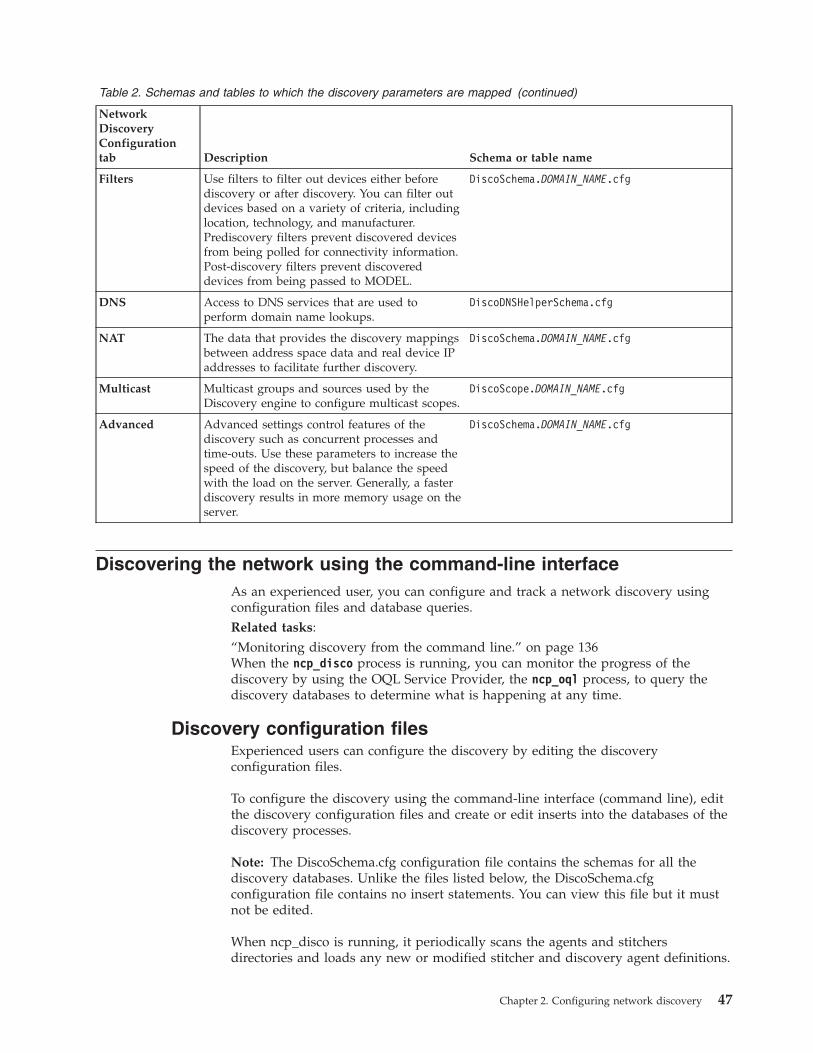
Table 2. Schemas and tables to which the discovery parameters are mapped (continued)
NetworkDiscoveryConfigurationtab Description Schema or table name
Filters Use filters to filter out devices either beforediscovery or after discovery. You can filter outdevices based on a variety of criteria, includinglocation, technology, and manufacturer.Prediscovery filters prevent discovered devicesfrom being polled for connectivity information.Post-discovery filters prevent discovereddevices from being passed to MODEL.
DiscoSchema.DOMAIN_NAME.cfg
DNS Access to DNS services that are used toperform domain name lookups.
DiscoDNSHelperSchema.cfg
NAT The data that provides the discovery mappingsbetween address space data and real device IPaddresses to facilitate further discovery.
DiscoSchema.DOMAIN_NAME.cfg
Multicast Multicast groups and sources used by theDiscovery engine to configure multicast scopes.
DiscoScope.DOMAIN_NAME.cfg
Advanced Advanced settings control features of thediscovery such as concurrent processes andtime-outs. Use these parameters to increase thespeed of the discovery, but balance the speedwith the load on the server. Generally, a fasterdiscovery results in more memory usage on theserver.
DiscoSchema.DOMAIN_NAME.cfg
Discovering the network using the command-line interfaceAs an experienced user, you can configure and track a network discovery usingconfiguration files and database queries.Related tasks:“Monitoring discovery from the command line.” on page 136When the ncp_disco process is running, you can monitor the progress of thediscovery by using the OQL Service Provider, the ncp_oql process, to query thediscovery databases to determine what is happening at any time.
Discovery configuration filesExperienced users can configure the discovery by editing the discoveryconfiguration files.
To configure the discovery using the command-line interface (command line), editthe discovery configuration files and create or edit inserts into the databases of thediscovery processes.
Note: The DiscoSchema.cfg configuration file contains the schemas for all thediscovery databases. Unlike the files listed below, the DiscoSchema.cfgconfiguration file contains no insert statements. You can view this file but it mustnot be edited.
When ncp_disco is running, it periodically scans the agents and stitchersdirectories and loads any new or modified stitcher and discovery agent definitions.
Chapter 2. Configuring network discovery 47
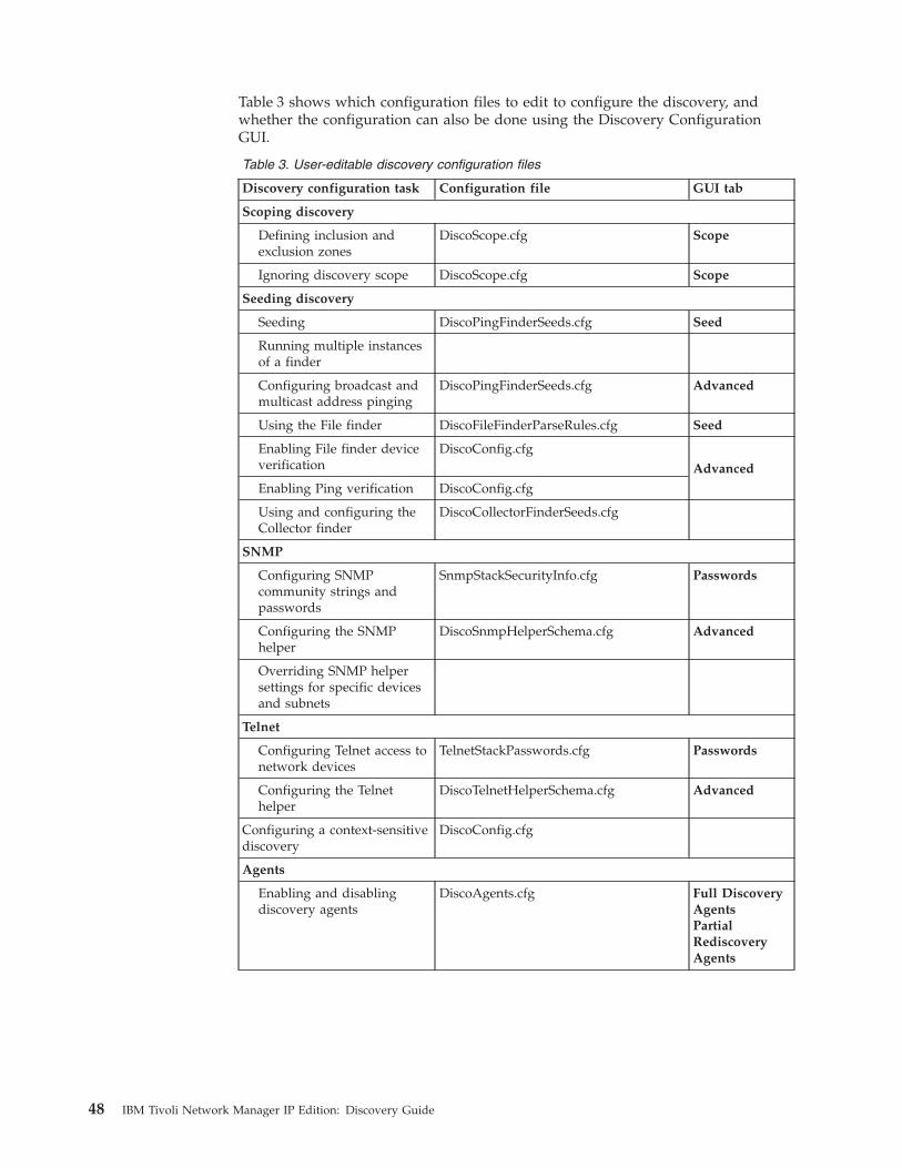
Table 3 shows which configuration files to edit to configure the discovery, andwhether the configuration can also be done using the Discovery ConfigurationGUI.
Table 3. User-editable discovery configuration files
Discovery configuration task Configuration file GUI tab
Scoping discovery
Defining inclusion andexclusion zones
DiscoScope.cfg Scope
Ignoring discovery scope DiscoScope.cfg Scope
Seeding discovery
Seeding DiscoPingFinderSeeds.cfg Seed
Running multiple instancesof a finder
Configuring broadcast andmulticast address pinging
DiscoPingFinderSeeds.cfg Advanced
Using the File finder DiscoFileFinderParseRules.cfg Seed
Enabling File finder deviceverification
DiscoConfig.cfgAdvanced
Enabling Ping verification DiscoConfig.cfg
Using and configuring theCollector finder
DiscoCollectorFinderSeeds.cfg
SNMP
Configuring SNMPcommunity strings andpasswords
SnmpStackSecurityInfo.cfg Passwords
Configuring the SNMPhelper
DiscoSnmpHelperSchema.cfg Advanced
Overriding SNMP helpersettings for specific devicesand subnets
Telnet
Configuring Telnet access tonetwork devices
TelnetStackPasswords.cfg Passwords
Configuring the Telnethelper
DiscoTelnetHelperSchema.cfg Advanced
Configuring a context-sensitivediscovery
DiscoConfig.cfg
Agents
Enabling and disablingdiscovery agents
DiscoAgents.cfg Full DiscoveryAgentsPartialRediscoveryAgents
48 IBM Tivoli Network Manager IP Edition: Discovery Guide
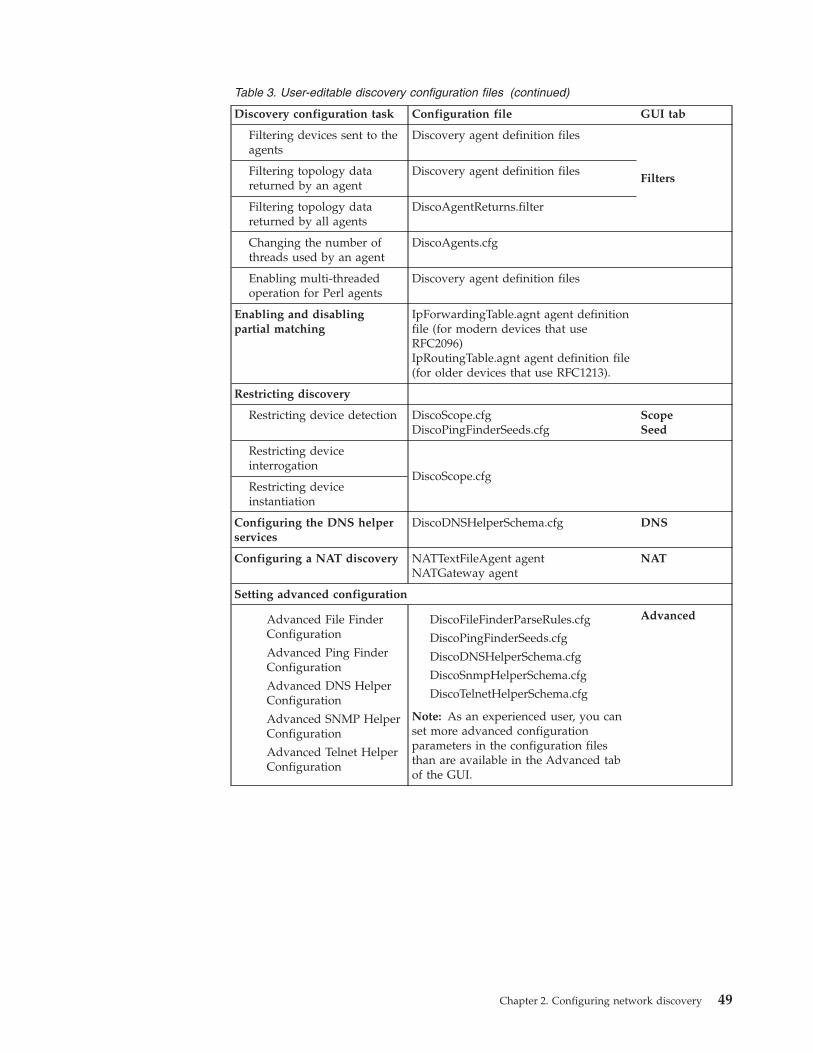
Table 3. User-editable discovery configuration files (continued)
Discovery configuration task Configuration file GUI tab
Filtering devices sent to theagents
Discovery agent definition files
FiltersFiltering topology datareturned by an agent
Discovery agent definition files
Filtering topology datareturned by all agents
DiscoAgentReturns.filter
Changing the number ofthreads used by an agent
DiscoAgents.cfg
Enabling multi-threadedoperation for Perl agents
Discovery agent definition files
Enabling and disablingpartial matching
IpForwardingTable.agnt agent definitionfile (for modern devices that useRFC2096)IpRoutingTable.agnt agent definition file(for older devices that use RFC1213).
Restricting discovery
Restricting device detection DiscoScope.cfgDiscoPingFinderSeeds.cfg
ScopeSeed
Restricting deviceinterrogation
DiscoScope.cfgRestricting deviceinstantiation
Configuring the DNS helperservices
DiscoDNSHelperSchema.cfg DNS
Configuring a NAT discovery NATTextFileAgent agentNATGateway agent
NAT
Setting advanced configuration
Advanced File FinderConfiguration
Advanced Ping FinderConfiguration
Advanced DNS HelperConfiguration
Advanced SNMP HelperConfiguration
Advanced Telnet HelperConfiguration
DiscoFileFinderParseRules.cfg
DiscoPingFinderSeeds.cfg
DiscoDNSHelperSchema.cfg
DiscoSnmpHelperSchema.cfg
DiscoTelnetHelperSchema.cfg
Note: As an experienced user, you canset more advanced configurationparameters in the configuration filesthan are available in the Advanced tabof the GUI.
Advanced
Chapter 2. Configuring network discovery 49
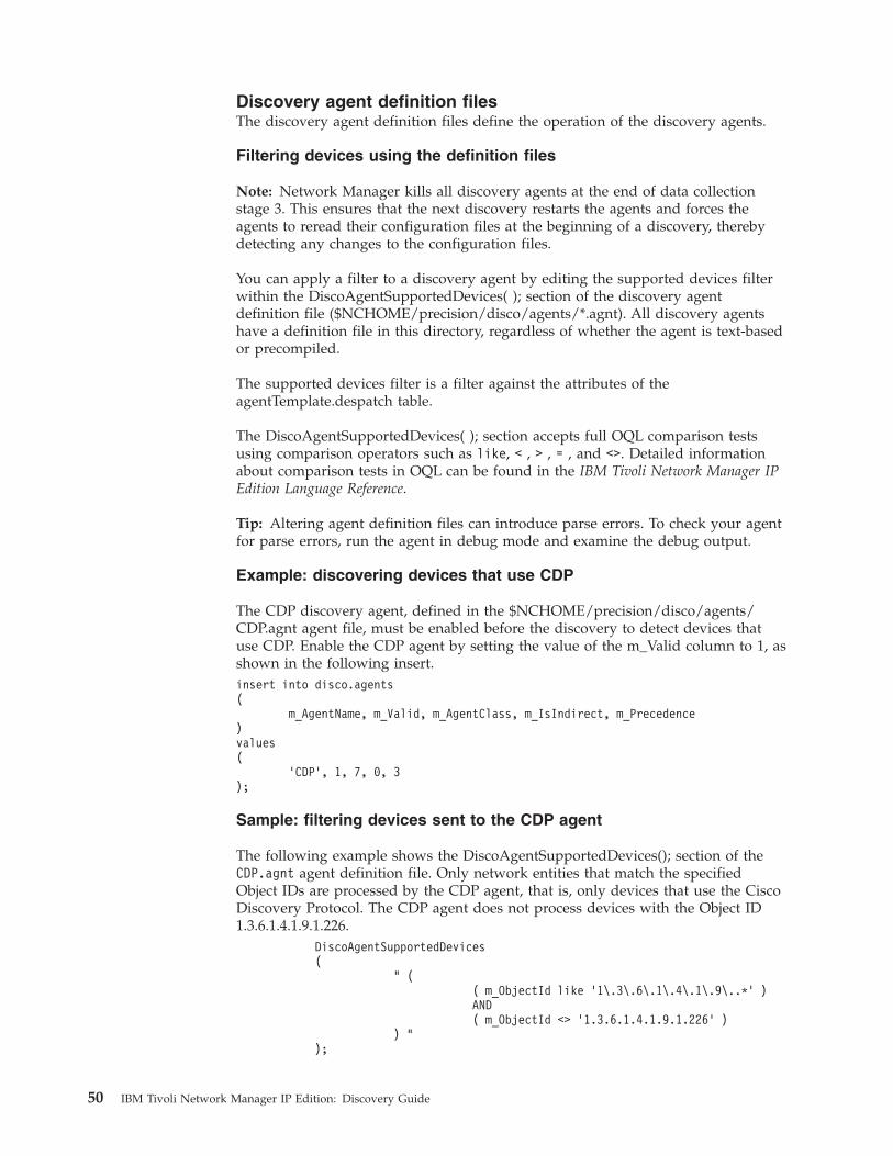
Discovery agent definition filesThe discovery agent definition files define the operation of the discovery agents.
Filtering devices using the definition files
Note: Network Manager kills all discovery agents at the end of data collectionstage 3. This ensures that the next discovery restarts the agents and forces theagents to reread their configuration files at the beginning of a discovery, therebydetecting any changes to the configuration files.
You can apply a filter to a discovery agent by editing the supported devices filterwithin the DiscoAgentSupportedDevices( ); section of the discovery agentdefinition file ($NCHOME/precision/disco/agents/*.agnt). All discovery agentshave a definition file in this directory, regardless of whether the agent is text-basedor precompiled.
The supported devices filter is a filter against the attributes of theagentTemplate.despatch table.
The DiscoAgentSupportedDevices( ); section accepts full OQL comparison testsusing comparison operators such as like, < , > , = , and <>. Detailed informationabout comparison tests in OQL can be found in the IBM Tivoli Network Manager IPEdition Language Reference.
Tip: Altering agent definition files can introduce parse errors. To check your agentfor parse errors, run the agent in debug mode and examine the debug output.
Example: discovering devices that use CDP
The CDP discovery agent, defined in the $NCHOME/precision/disco/agents/CDP.agnt agent file, must be enabled before the discovery to detect devices thatuse CDP. Enable the CDP agent by setting the value of the m_Valid column to 1, asshown in the following insert.insert into disco.agents(
m_AgentName, m_Valid, m_AgentClass, m_IsIndirect, m_Precedence)values(
’CDP’, 1, 7, 0, 3);
Sample: filtering devices sent to the CDP agent
The following example shows the DiscoAgentSupportedDevices(); section of theCDP.agnt agent definition file. Only network entities that match the specifiedObject IDs are processed by the CDP agent, that is, only devices that use the CiscoDiscovery Protocol. The CDP agent does not process devices with the Object ID1.3.6.1.4.1.9.1.226.
DiscoAgentSupportedDevices(
" (( m_ObjectId like ’1\.3\.6\.1\.4\.1\.9\..*’ )AND( m_ObjectId <> ’1.3.6.1.4.1.9.1.226’ )
) ");
50 IBM Tivoli Network Manager IP Edition: Discovery Guide
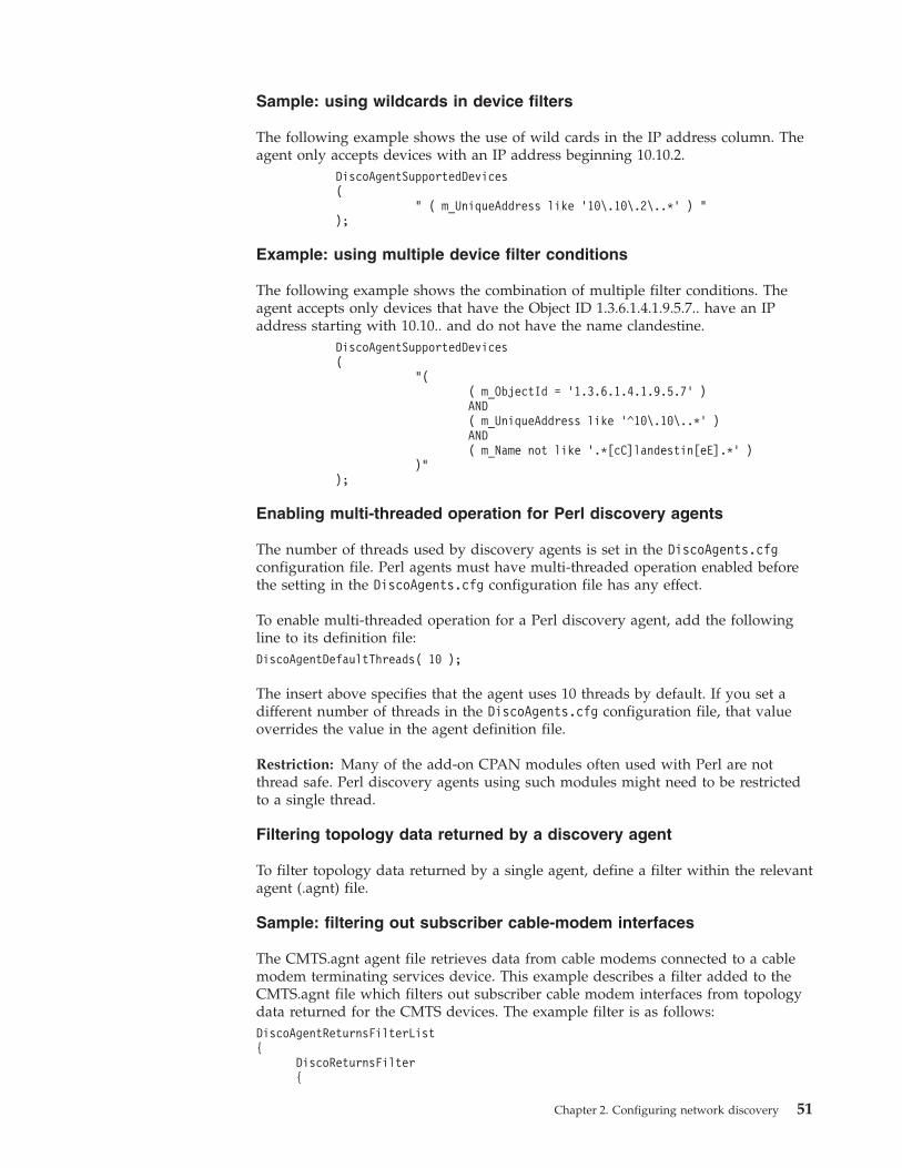
Sample: using wildcards in device filters
The following example shows the use of wild cards in the IP address column. Theagent only accepts devices with an IP address beginning 10.10.2.
DiscoAgentSupportedDevices(
" ( m_UniqueAddress like ’10\.10\.2\..*’ ) ");
Example: using multiple device filter conditions
The following example shows the combination of multiple filter conditions. Theagent accepts only devices that have the Object ID 1.3.6.1.4.1.9.5.7.. have an IPaddress starting with 10.10.. and do not have the name clandestine.
DiscoAgentSupportedDevices(
"(( m_ObjectId = ’1.3.6.1.4.1.9.5.7’ )AND( m_UniqueAddress like ’^10\.10\..*’ )AND( m_Name not like ’.*[cC]landestin[eE].*’ )
)");
Enabling multi-threaded operation for Perl discovery agents
The number of threads used by discovery agents is set in the DiscoAgents.cfgconfiguration file. Perl agents must have multi-threaded operation enabled beforethe setting in the DiscoAgents.cfg configuration file has any effect.
To enable multi-threaded operation for a Perl discovery agent, add the followingline to its definition file:DiscoAgentDefaultThreads( 10 );
The insert above specifies that the agent uses 10 threads by default. If you set adifferent number of threads in the DiscoAgents.cfg configuration file, that valueoverrides the value in the agent definition file.
Restriction: Many of the add-on CPAN modules often used with Perl are notthread safe. Perl discovery agents using such modules might need to be restrictedto a single thread.
Filtering topology data returned by a discovery agent
To filter topology data returned by a single agent, define a filter within the relevantagent (.agnt) file.
Sample: filtering out subscriber cable-modem interfaces
The CMTS.agnt agent file retrieves data from cable modems connected to a cablemodem terminating services device. This example describes a filter added to theCMTS.agnt file which filters out subscriber cable modem interfaces from topologydata returned for the CMTS devices. The example filter is as follows:DiscoAgentReturnsFilterList{
DiscoReturnsFilter{
Chapter 2. Configuring network discovery 51
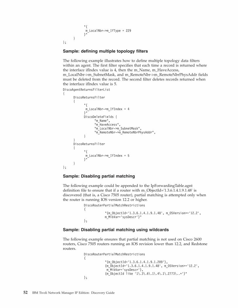
"(m_LocalNbr->m_IfType = 229)"
}};
Sample: defining multiple topology filters
The following example illustrates how to define multiple topology data filterswithin an agent. The first filter specifies that each time a record is returned wherethe interface ifIndex value is 4, then the m_Name, m_HaveAccess,m_LocalNbr->m_SubnetMask, and m_RemoteNbr->m_RemoteNbrPhysAddr fieldsmust be deleted from the record. The second filter deletes records returned whenthe interface ifIndex value is 5.DiscoAgentReturnsFilterList{
DiscoReturnsFilter{
"(m_LocalNbr->m_IfIndex = 4)"DiscoDeleteFields {
"m_Name","m_HaveAccess","m_LocalNbr->m_SubnetMask","m_RemoteNbr->m_RemoteNbrPhysAddr",
}}DiscoReturnsFilter{
"(m_LocalNbr->m_IfIndex = 5)"
}};
Sample: Disabling partial matching
The following example could be appended to the IpForwardingTable.agntdefinition file to ensure that if a router with m_ObjectId='1.3.6.1.4.1.9.1.48' isdiscovered (that is, a Cisco 7505 router), partial matching is attempted only whenthe router is running IOS version 12.2 or higher.
DiscoRouterPartialMatchRestrictions(
"(m_ObjectId=’1.3.6.1.4.1.9.1.48’, m_OSVersion>=’12.2’,m_MibVar=’sysDescr’)"
);
Sample: Disabling partial matching using wildcards
The following example ensures that partial matching is not used on Cisco 2600routers, Cisco 7505 routers running an IOS revision lower than 12.2, and Redstonerouters.
DiscoRouterPartialMatchRestrictions(
"(m_ObjectId=’1.3.6.1.4.1.9.1.209’),(m_ObjectId=’1.3.6.1.4.1.9.1.48’, m_OSVersion>=’12.2’,m_MibVar=’sysDescr’),
(m_ObjectId like ’1\.3\.6\.1\.4\.1\.2773\..*’)");
52 IBM Tivoli Network Manager IP Edition: Discovery Guide
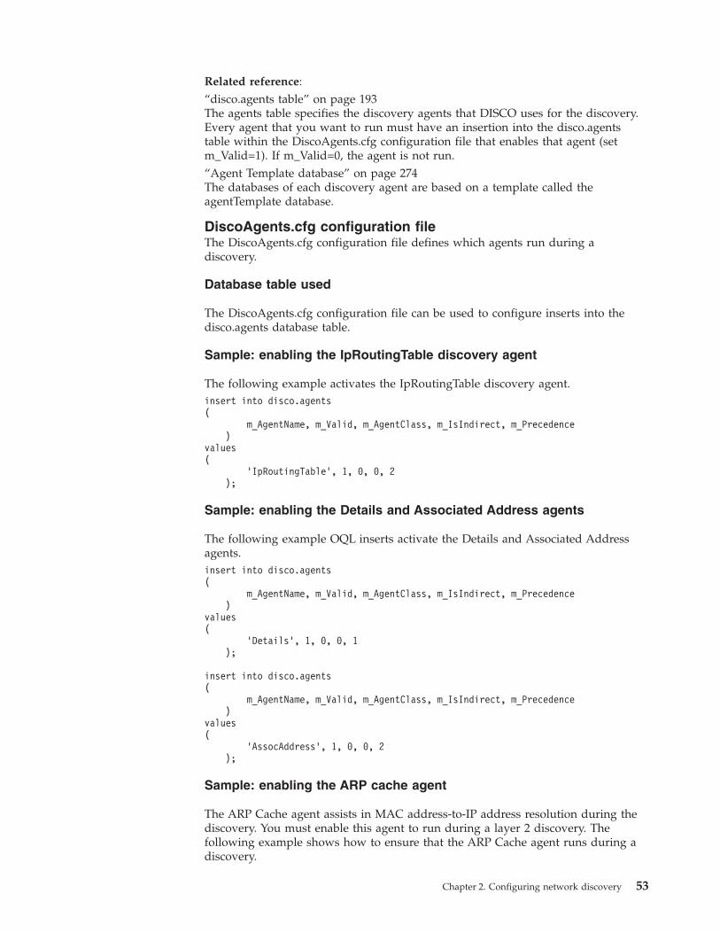
Related reference:“disco.agents table” on page 193The agents table specifies the discovery agents that DISCO uses for the discovery.Every agent that you want to run must have an insertion into the disco.agentstable within the DiscoAgents.cfg configuration file that enables that agent (setm_Valid=1). If m_Valid=0, the agent is not run.“Agent Template database” on page 274The databases of each discovery agent are based on a template called theagentTemplate database.
DiscoAgents.cfg configuration fileThe DiscoAgents.cfg configuration file defines which agents run during adiscovery.
Database table used
The DiscoAgents.cfg configuration file can be used to configure inserts into thedisco.agents database table.
Sample: enabling the IpRoutingTable discovery agent
The following example activates the IpRoutingTable discovery agent.insert into disco.agents(
m_AgentName, m_Valid, m_AgentClass, m_IsIndirect, m_Precedence)
values(
’IpRoutingTable’, 1, 0, 0, 2);
Sample: enabling the Details and Associated Address agents
The following example OQL inserts activate the Details and Associated Addressagents.insert into disco.agents(
m_AgentName, m_Valid, m_AgentClass, m_IsIndirect, m_Precedence)
values(
’Details’, 1, 0, 0, 1);
insert into disco.agents(
m_AgentName, m_Valid, m_AgentClass, m_IsIndirect, m_Precedence)
values(
’AssocAddress’, 1, 0, 0, 2);
Sample: enabling the ARP cache agent
The ARP Cache agent assists in MAC address-to-IP address resolution during thediscovery. You must enable this agent to run during a layer 2 discovery. Thefollowing example shows how to ensure that the ARP Cache agent runs during adiscovery.
Chapter 2. Configuring network discovery 53
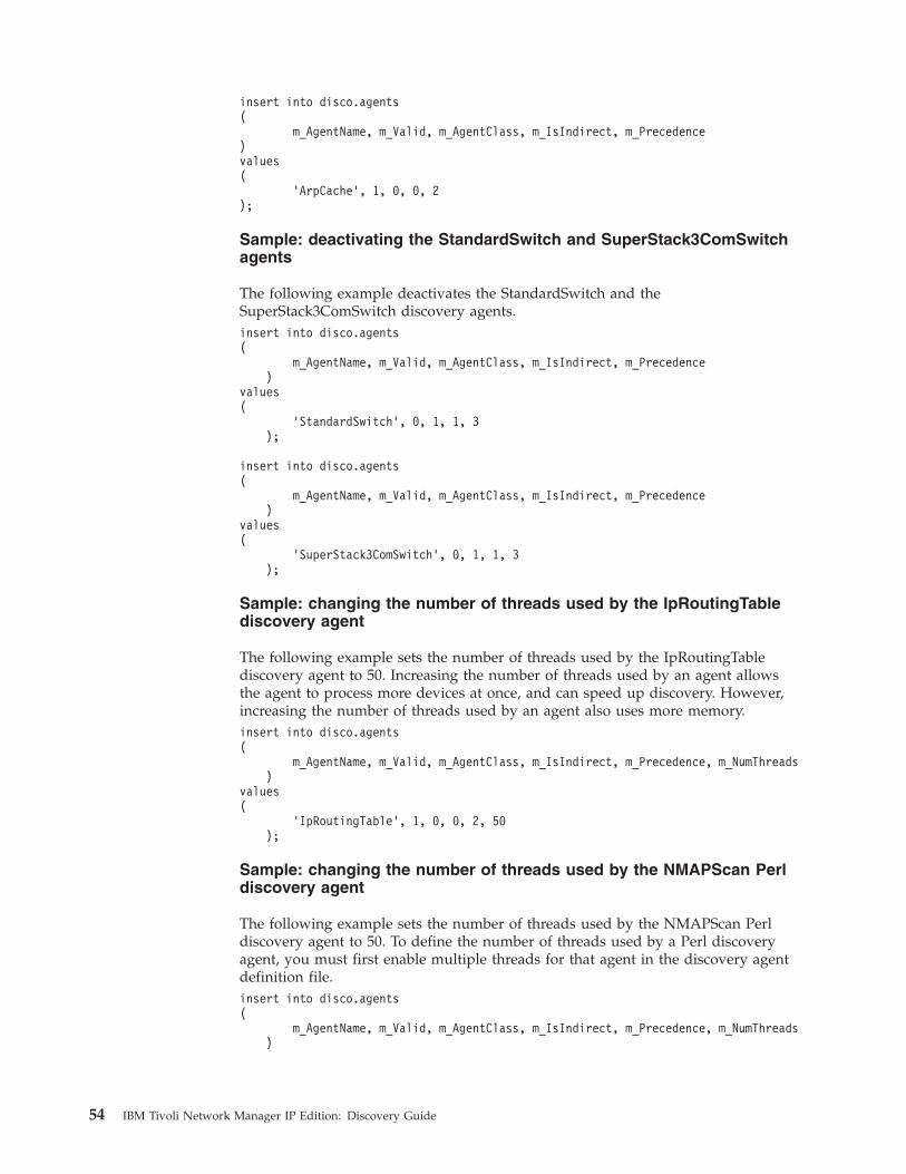
insert into disco.agents(
m_AgentName, m_Valid, m_AgentClass, m_IsIndirect, m_Precedence)values(
’ArpCache’, 1, 0, 0, 2);
Sample: deactivating the StandardSwitch and SuperStack3ComSwitchagents
The following example deactivates the StandardSwitch and theSuperStack3ComSwitch discovery agents.insert into disco.agents(
m_AgentName, m_Valid, m_AgentClass, m_IsIndirect, m_Precedence)
values(
’StandardSwitch’, 0, 1, 1, 3);
insert into disco.agents(
m_AgentName, m_Valid, m_AgentClass, m_IsIndirect, m_Precedence)
values(
’SuperStack3ComSwitch’, 0, 1, 1, 3);
Sample: changing the number of threads used by the IpRoutingTablediscovery agent
The following example sets the number of threads used by the IpRoutingTablediscovery agent to 50. Increasing the number of threads used by an agent allowsthe agent to process more devices at once, and can speed up discovery. However,increasing the number of threads used by an agent also uses more memory.insert into disco.agents(
m_AgentName, m_Valid, m_AgentClass, m_IsIndirect, m_Precedence, m_NumThreads)
values(
’IpRoutingTable’, 1, 0, 0, 2, 50);
Sample: changing the number of threads used by the NMAPScan Perldiscovery agent
The following example sets the number of threads used by the NMAPScan Perldiscovery agent to 50. To define the number of threads used by a Perl discoveryagent, you must first enable multiple threads for that agent in the discovery agentdefinition file.insert into disco.agents(
m_AgentName, m_Valid, m_AgentClass, m_IsIndirect, m_Precedence, m_NumThreads)
54 IBM Tivoli Network Manager IP Edition: Discovery Guide
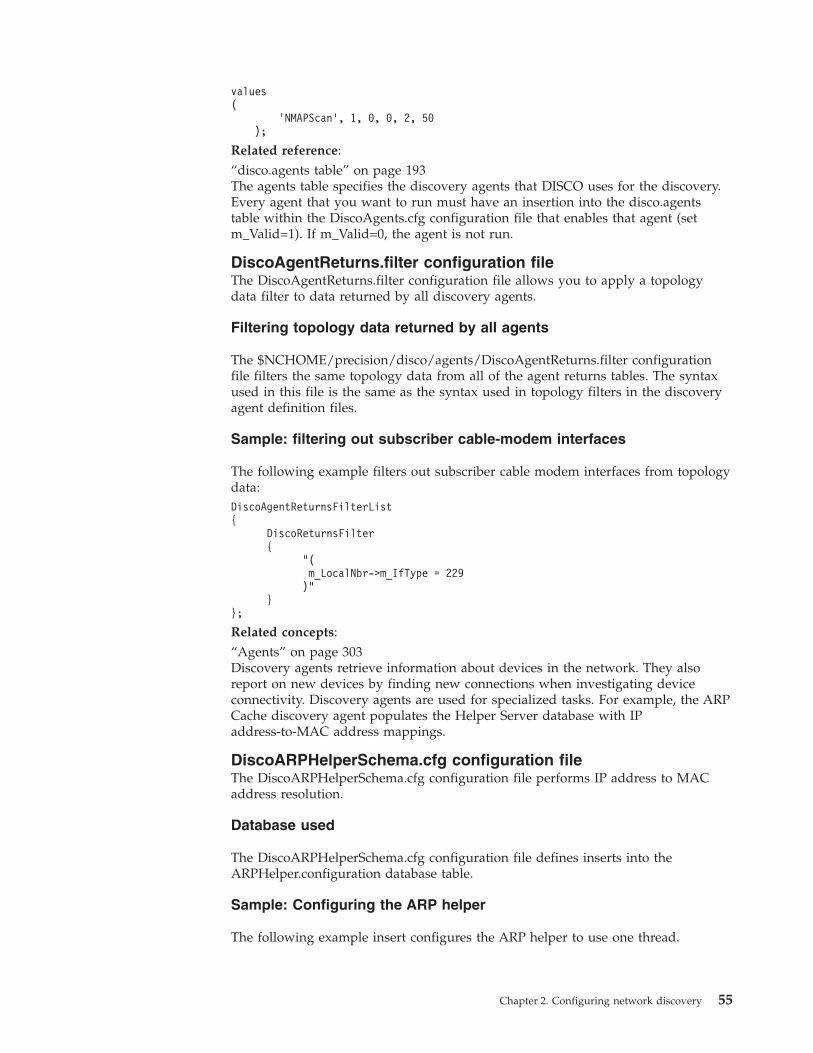
values(
’NMAPScan’, 1, 0, 0, 2, 50);
Related reference:“disco.agents table” on page 193The agents table specifies the discovery agents that DISCO uses for the discovery.Every agent that you want to run must have an insertion into the disco.agentstable within the DiscoAgents.cfg configuration file that enables that agent (setm_Valid=1). If m_Valid=0, the agent is not run.
DiscoAgentReturns.filter configuration fileThe DiscoAgentReturns.filter configuration file allows you to apply a topologydata filter to data returned by all discovery agents.
Filtering topology data returned by all agents
The $NCHOME/precision/disco/agents/DiscoAgentReturns.filter configurationfile filters the same topology data from all of the agent returns tables. The syntaxused in this file is the same as the syntax used in topology filters in the discoveryagent definition files.
Sample: filtering out subscriber cable-modem interfaces
The following example filters out subscriber cable modem interfaces from topologydata:DiscoAgentReturnsFilterList{
DiscoReturnsFilter{
"(m_LocalNbr->m_IfType = 229)"
}};
Related concepts:“Agents” on page 303Discovery agents retrieve information about devices in the network. They alsoreport on new devices by finding new connections when investigating deviceconnectivity. Discovery agents are used for specialized tasks. For example, the ARPCache discovery agent populates the Helper Server database with IPaddress-to-MAC address mappings.
DiscoARPHelperSchema.cfg configuration fileThe DiscoARPHelperSchema.cfg configuration file performs IP address to MACaddress resolution.
Database used
The DiscoARPHelperSchema.cfg configuration file defines inserts into theARPHelper.configuration database table.
Sample: Configuring the ARP helper
The following example insert configures the ARP helper to use one thread.
Chapter 2. Configuring network discovery 55
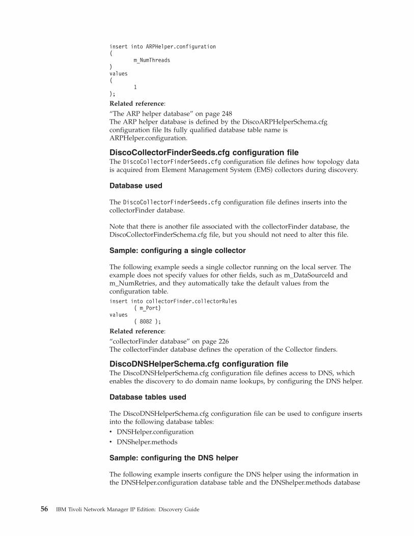
insert into ARPHelper.configuration(
m_NumThreads)values(
1);
Related reference:“The ARP helper database” on page 248The ARP helper database is defined by the DiscoARPHelperSchema.cfgconfiguration file Its fully qualified database table name isARPHelper.configuration.
DiscoCollectorFinderSeeds.cfg configuration fileThe DiscoCollectorFinderSeeds.cfg configuration file defines how topology datais acquired from Element Management System (EMS) collectors during discovery.
Database used
The DiscoCollectorFinderSeeds.cfg configuration file defines inserts into thecollectorFinder database.
Note that there is another file associated with the collectorFinder database, theDiscoCollectorFinderSchema.cfg file, but you should not need to alter this file.
Sample: configuring a single collector
The following example seeds a single collector running on the local server. Theexample does not specify values for other fields, such as m_DataSourceId andm_NumRetries, and they automatically take the default values from theconfiguration table.insert into collectorFinder.collectorRules
( m_Port)values
( 8082 );
Related reference:“collectorFinder database” on page 226The collectorFinder database defines the operation of the Collector finders.
DiscoDNSHelperSchema.cfg configuration fileThe DiscoDNSHelperSchema.cfg configuration file defines access to DNS, whichenables the discovery to do domain name lookups, by configuring the DNS helper.
Database tables used
The DiscoDNSHelperSchema.cfg configuration file can be used to configure insertsinto the following database tables:v DNSHelper.configurationv DNShelper.methods
Sample: configuring the DNS helper
The following example inserts configure the DNS helper using the information inthe DNSHelper.configuration database table and the DNShelper.methods database
56 IBM Tivoli Network Manager IP Edition: Discovery Guide
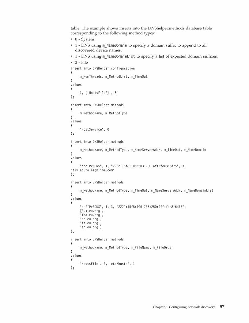
table. The example shows inserts into the DNShelper.methods database tablecorresponding to the following method types:v 0 - Systemv 1 - DNS using m_NameDomain to specify a domain suffix to append to all
discovered device names.v 1 - DNS using m_NameDomainList to specify a list of expected domain suffixes.v 2 - Fileinsert into DNSHelper.configuration(
m_NumThreads, m_MethodList, m_TimeOut)values(
1, [’HostsFile’] , 5);
insert into DNSHelper.methods(
m_MethodName, m_MethodType)values(
"HostService", 0);
insert into DNSHelper.methods(
m_MethodName, m_MethodType, m_NameServerAddr, m_TimeOut, m_NameDomain)values(
"abcIPv6DNS", 1, "2222:15f8:106:203:250:4ff:fee8:6d75", 3,"tivlab.raleigh.ibm.com");
insert into DNSHelper.methods(
m_MethodName, m_MethodType, m_TimeOut, m_NameServerAddr, m_NameDomainList)values(
"defIPv6DNS", 1, 3, "2222:15f8:106:203:250:4ff:fee8:6d75",[’uk.eu.org’,’fra.eu.org’,’de.eu.org’,’it.eu.org’,’sp.eu.org’]
);
insert into DNSHelper.methods(
m_MethodName, m_MethodType, m_FileName, m_FileOrder)values(
’HostsFile’, 2, ’etc/hosts’, 1);
Chapter 2. Configuring network discovery 57
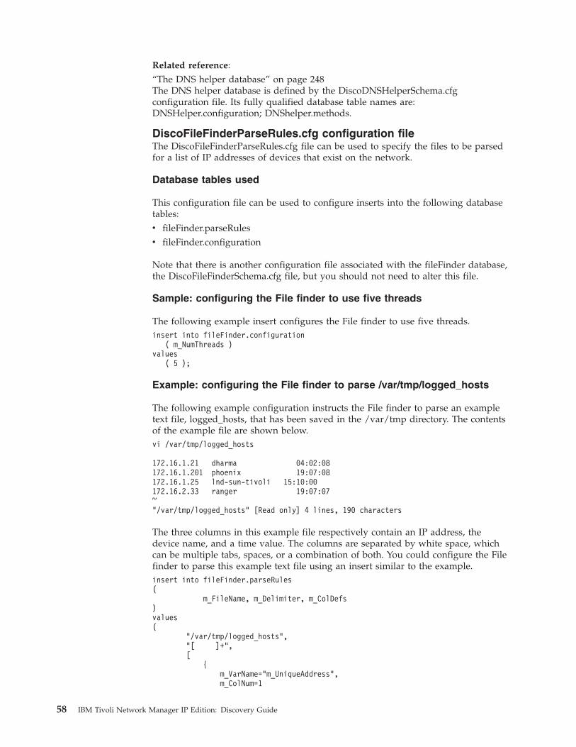
Related reference:“The DNS helper database” on page 248The DNS helper database is defined by the DiscoDNSHelperSchema.cfgconfiguration file. Its fully qualified database table names are:DNSHelper.configuration; DNShelper.methods.
DiscoFileFinderParseRules.cfg configuration fileThe DiscoFileFinderParseRules.cfg file can be used to specify the files to be parsedfor a list of IP addresses of devices that exist on the network.
Database tables used
This configuration file can be used to configure inserts into the following databasetables:v fileFinder.parseRulesv fileFinder.configuration
Note that there is another configuration file associated with the fileFinder database,the DiscoFileFinderSchema.cfg file, but you should not need to alter this file.
Sample: configuring the File finder to use five threads
The following example insert configures the File finder to use five threads.insert into fileFinder.configuration
( m_NumThreads )values
( 5 );
Example: configuring the File finder to parse /var/tmp/logged_hosts
The following example configuration instructs the File finder to parse an exampletext file, logged_hosts, that has been saved in the /var/tmp directory. The contentsof the example file are shown below.vi /var/tmp/logged_hosts
172.16.1.21 dharma 04:02:08172.16.1.201 phoenix 19:07:08172.16.1.25 lnd-sun-tivoli 15:10:00172.16.2.33 ranger 19:07:07~"/var/tmp/logged_hosts" [Read only] 4 lines, 190 characters
The three columns in this example file respectively contain an IP address, thedevice name, and a time value. The columns are separated by white space, whichcan be multiple tabs, spaces, or a combination of both. You could configure the Filefinder to parse this example text file using an insert similar to the example.insert into fileFinder.parseRules(
m_FileName, m_Delimiter, m_ColDefs)values(
"/var/tmp/logged_hosts","[ ]+",[
{m_VarName="m_UniqueAddress",m_ColNum=1
58 IBM Tivoli Network Manager IP Edition: Discovery Guide
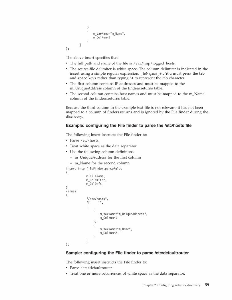
},{
m_VarName="m_Name",m_ColNum=2
}]
);
The above insert specifies that:v The full path and name of the file is /var/tmp/logged_hosts.v The source-file delimiter is white space. The column delimiter is indicated in the
insert using a simple regular expression, [ tab space ]+ . You must press the taband space keys rather than typing \t to represent the tab character.
v The first column contains IP addresses and must be mapped to them_UniqueAddress column of the finders.returns table.
v The second column contains host names and must be mapped to the m_Namecolumn of the finders.returns table.
Because the third column in the example text file is not relevant, it has not beenmapped to a column of finders.returns and is ignored by the File finder during thediscovery.
Example: configuring the File finder to parse the /etc/hosts file
The following insert instructs the File finder to:v Parse /etc/hosts.v Treat white space as the data separator.v Use the following column definitions:
– m_UniqueAddress for the first column– m_Name for the second column
insert into fileFinder.parseRules(
m_FileName,m_Delimiter,m_ColDefs
)values(
"/etc/hosts","[ ]",[
{m_VarName="m_UniqueAddress",m_ColNum=1
},{
m_VarName="m_Name",m_ColNum=2
}]
);
Sample: configuring the File finder to parse /etc/defaultrouter
The following insert instructs the File finder to:v Parse /etc/defaultrouter.v Treat one or more occurrences of white space as the data separator.
Chapter 2. Configuring network discovery 59
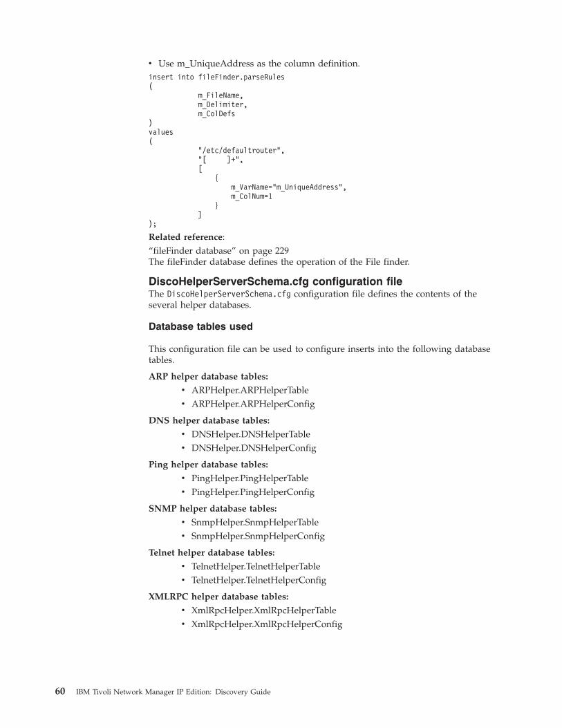
v Use m_UniqueAddress as the column definition.insert into fileFinder.parseRules(
m_FileName,m_Delimiter,m_ColDefs
)values(
"/etc/defaultrouter","[ ]+",[
{m_VarName="m_UniqueAddress",m_ColNum=1
}]
);
Related reference:“fileFinder database” on page 229The fileFinder database defines the operation of the File finder.
DiscoHelperServerSchema.cfg configuration fileThe DiscoHelperServerSchema.cfg configuration file defines the contents of theseveral helper databases.
Database tables used
This configuration file can be used to configure inserts into the following databasetables.
ARP helper database tables:
v ARPHelper.ARPHelperTablev ARPHelper.ARPHelperConfig
DNS helper database tables:
v DNSHelper.DNSHelperTablev DNSHelper.DNSHelperConfig
Ping helper database tables:
v PingHelper.PingHelperTablev PingHelper.PingHelperConfig
SNMP helper database tables:
v SnmpHelper.SnmpHelperTablev SnmpHelper.SnmpHelperConfig
Telnet helper database tables:
v TelnetHelper.TelnetHelperTablev TelnetHelper.TelnetHelperConfig
XMLRPC helper database tables:
v XmlRpcHelper.XmlRpcHelperTablev XmlRpcHelper.XmlRpcHelperConfig
60 IBM Tivoli Network Manager IP Edition: Discovery Guide
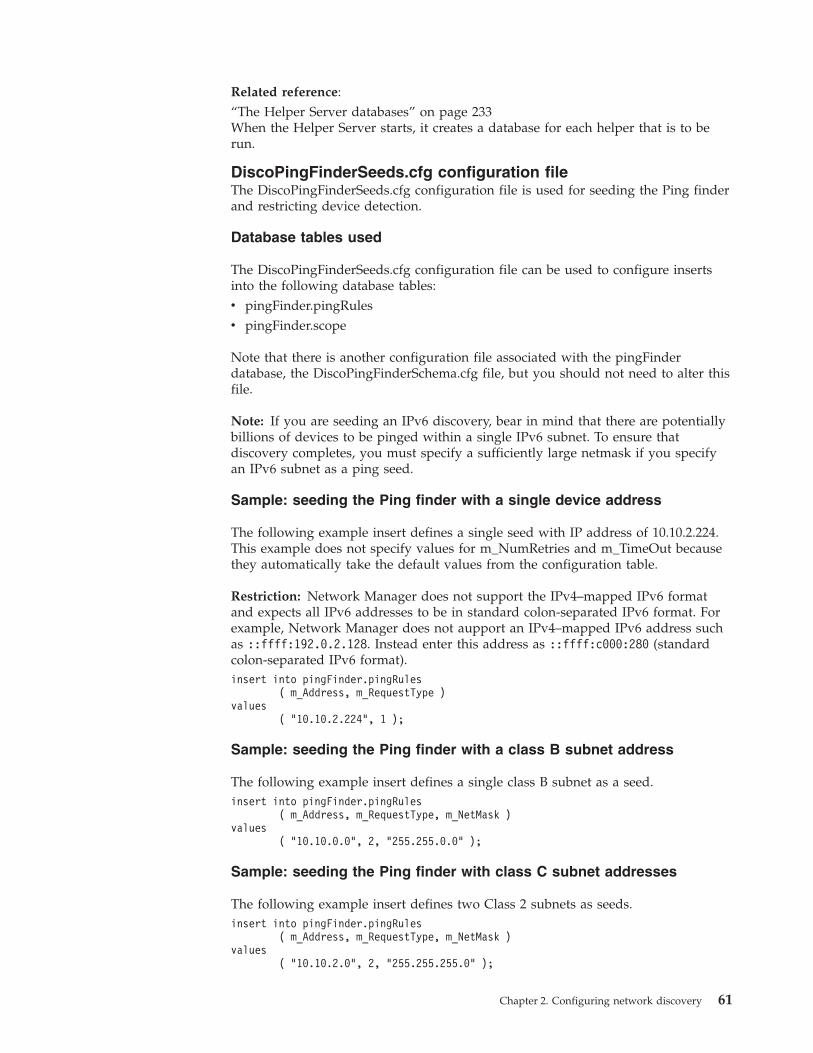
Related reference:“The Helper Server databases” on page 233When the Helper Server starts, it creates a database for each helper that is to berun.
DiscoPingFinderSeeds.cfg configuration fileThe DiscoPingFinderSeeds.cfg configuration file is used for seeding the Ping finderand restricting device detection.
Database tables used
The DiscoPingFinderSeeds.cfg configuration file can be used to configure insertsinto the following database tables:v pingFinder.pingRulesv pingFinder.scope
Note that there is another configuration file associated with the pingFinderdatabase, the DiscoPingFinderSchema.cfg file, but you should not need to alter thisfile.
Note: If you are seeding an IPv6 discovery, bear in mind that there are potentiallybillions of devices to be pinged within a single IPv6 subnet. To ensure thatdiscovery completes, you must specify a sufficiently large netmask if you specifyan IPv6 subnet as a ping seed.
Sample: seeding the Ping finder with a single device address
The following example insert defines a single seed with IP address of 10.10.2.224.This example does not specify values for m_NumRetries and m_TimeOut becausethey automatically take the default values from the configuration table.
Restriction: Network Manager does not support the IPv4–mapped IPv6 formatand expects all IPv6 addresses to be in standard colon-separated IPv6 format. Forexample, Network Manager does not aupport an IPv4–mapped IPv6 address suchas ::ffff:192.0.2.128. Instead enter this address as ::ffff:c000:280 (standardcolon-separated IPv6 format).insert into pingFinder.pingRules
( m_Address, m_RequestType )values
( "10.10.2.224", 1 );
Sample: seeding the Ping finder with a class B subnet address
The following example insert defines a single class B subnet as a seed.insert into pingFinder.pingRules
( m_Address, m_RequestType, m_NetMask )values
( "10.10.0.0", 2, "255.255.0.0" );
Sample: seeding the Ping finder with class C subnet addresses
The following example insert defines two Class 2 subnets as seeds.insert into pingFinder.pingRules
( m_Address, m_RequestType, m_NetMask )values
( "10.10.2.0", 2, "255.255.255.0" );
Chapter 2. Configuring network discovery 61
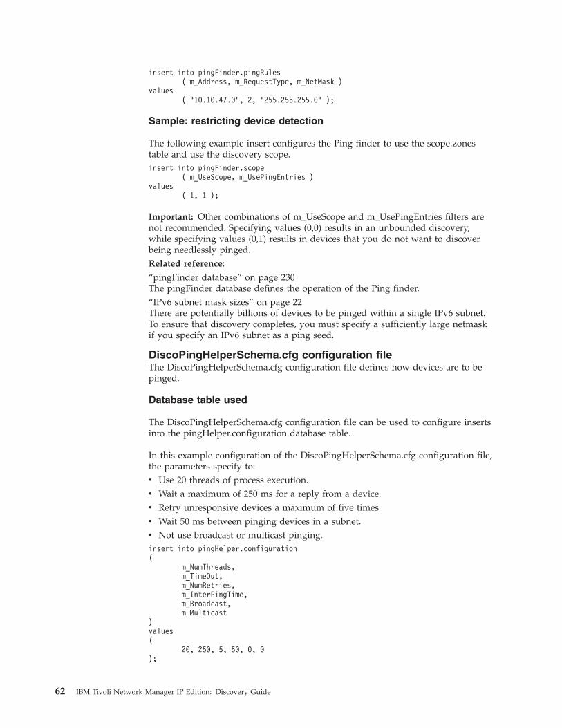
insert into pingFinder.pingRules( m_Address, m_RequestType, m_NetMask )
values( "10.10.47.0", 2, "255.255.255.0" );
Sample: restricting device detection
The following example insert configures the Ping finder to use the scope.zonestable and use the discovery scope.insert into pingFinder.scope
( m_UseScope, m_UsePingEntries )values
( 1, 1 );
Important: Other combinations of m_UseScope and m_UsePingEntries filters arenot recommended. Specifying values (0,0) results in an unbounded discovery,while specifying values (0,1) results in devices that you do not want to discoverbeing needlessly pinged.Related reference:“pingFinder database” on page 230The pingFinder database defines the operation of the Ping finder.“IPv6 subnet mask sizes” on page 22There are potentially billions of devices to be pinged within a single IPv6 subnet.To ensure that discovery completes, you must specify a sufficiently large netmaskif you specify an IPv6 subnet as a ping seed.
DiscoPingHelperSchema.cfg configuration fileThe DiscoPingHelperSchema.cfg configuration file defines how devices are to bepinged.
Database table used
The DiscoPingHelperSchema.cfg configuration file can be used to configure insertsinto the pingHelper.configuration database table.
In this example configuration of the DiscoPingHelperSchema.cfg configuration file,the parameters specify to:v Use 20 threads of process execution.v Wait a maximum of 250 ms for a reply from a device.v Retry unresponsive devices a maximum of five times.v Wait 50 ms between pinging devices in a subnet.v Not use broadcast or multicast pinging.insert into pingHelper.configuration(
m_NumThreads,m_TimeOut,m_NumRetries,m_InterPingTime,m_Broadcast,m_Multicast
)values(
20, 250, 5, 50, 0, 0);
62 IBM Tivoli Network Manager IP Edition: Discovery Guide
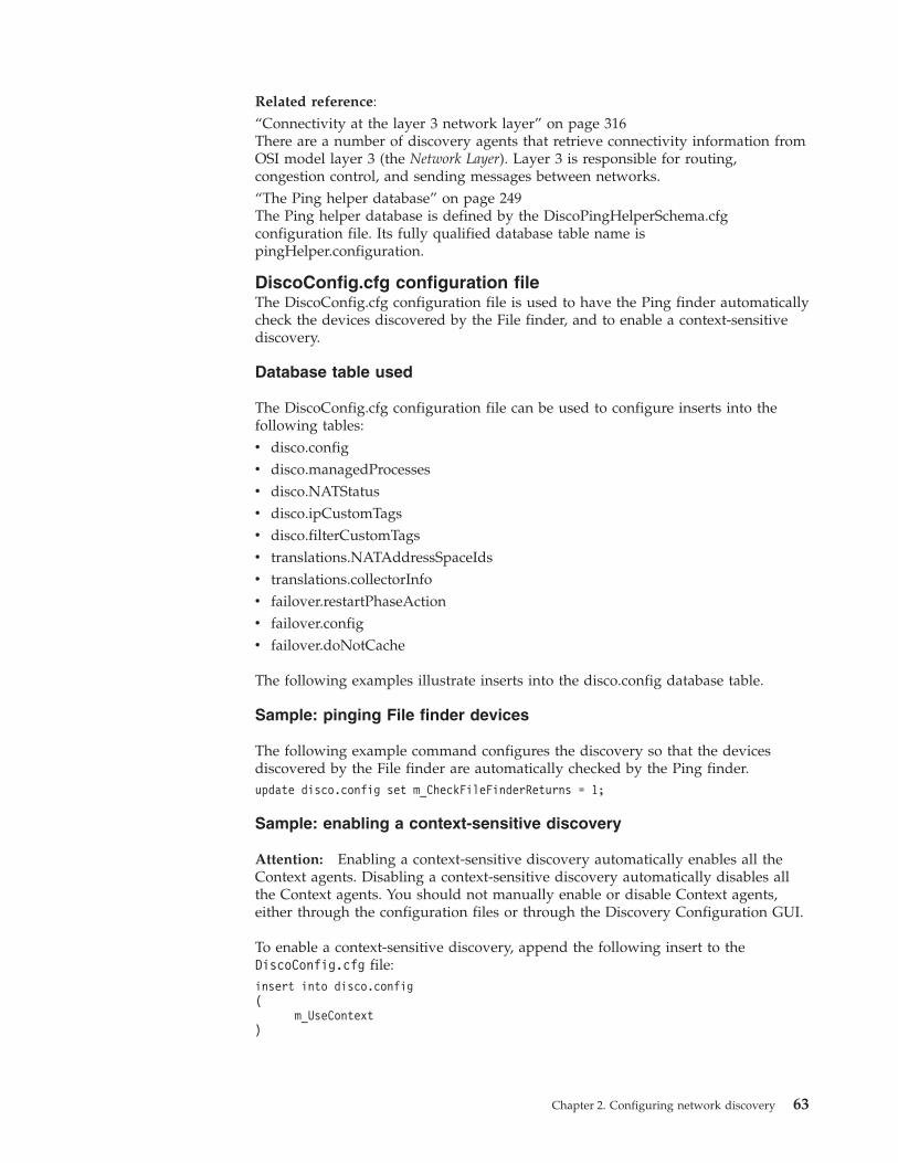
Related reference:“Connectivity at the layer 3 network layer” on page 316There are a number of discovery agents that retrieve connectivity information fromOSI model layer 3 (the Network Layer). Layer 3 is responsible for routing,congestion control, and sending messages between networks.“The Ping helper database” on page 249The Ping helper database is defined by the DiscoPingHelperSchema.cfgconfiguration file. Its fully qualified database table name ispingHelper.configuration.
DiscoConfig.cfg configuration fileThe DiscoConfig.cfg configuration file is used to have the Ping finder automaticallycheck the devices discovered by the File finder, and to enable a context-sensitivediscovery.
Database table used
The DiscoConfig.cfg configuration file can be used to configure inserts into thefollowing tables:v disco.configv disco.managedProcessesv disco.NATStatusv disco.ipCustomTagsv disco.filterCustomTagsv translations.NATAddressSpaceIdsv translations.collectorInfov failover.restartPhaseActionv failover.configv failover.doNotCache
The following examples illustrate inserts into the disco.config database table.
Sample: pinging File finder devices
The following example command configures the discovery so that the devicesdiscovered by the File finder are automatically checked by the Ping finder.update disco.config set m_CheckFileFinderReturns = 1;
Sample: enabling a context-sensitive discovery
Attention: Enabling a context-sensitive discovery automatically enables all theContext agents. Disabling a context-sensitive discovery automatically disables allthe Context agents. You should not manually enable or disable Context agents,either through the configuration files or through the Discovery Configuration GUI.
To enable a context-sensitive discovery, append the following insert to theDiscoConfig.cfg file:insert into disco.config(
m_UseContext)
Chapter 2. Configuring network discovery 63
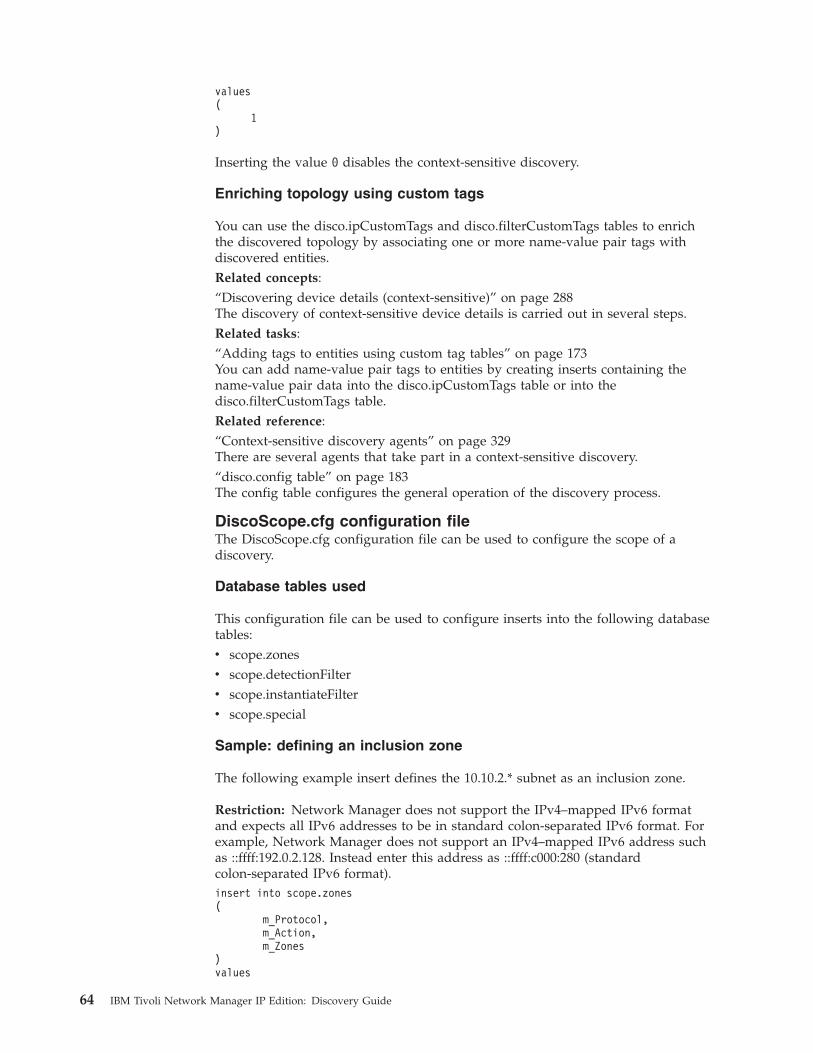
values(
1)
Inserting the value 0 disables the context-sensitive discovery.
Enriching topology using custom tags
You can use the disco.ipCustomTags and disco.filterCustomTags tables to enrichthe discovered topology by associating one or more name-value pair tags withdiscovered entities.Related concepts:“Discovering device details (context-sensitive)” on page 288The discovery of context-sensitive device details is carried out in several steps.Related tasks:“Adding tags to entities using custom tag tables” on page 173You can add name-value pair tags to entities by creating inserts containing thename-value pair data into the disco.ipCustomTags table or into thedisco.filterCustomTags table.Related reference:“Context-sensitive discovery agents” on page 329There are several agents that take part in a context-sensitive discovery.“disco.config table” on page 183The config table configures the general operation of the discovery process.
DiscoScope.cfg configuration fileThe DiscoScope.cfg configuration file can be used to configure the scope of adiscovery.
Database tables used
This configuration file can be used to configure inserts into the following databasetables:v scope.zonesv scope.detectionFilterv scope.instantiateFilterv scope.special
Sample: defining an inclusion zone
The following example insert defines the 10.10.2.* subnet as an inclusion zone.
Restriction: Network Manager does not support the IPv4–mapped IPv6 formatand expects all IPv6 addresses to be in standard colon-separated IPv6 format. Forexample, Network Manager does not support an IPv4–mapped IPv6 address suchas ::ffff:192.0.2.128. Instead enter this address as ::ffff:c000:280 (standardcolon-separated IPv6 format).insert into scope.zones(
m_Protocol,m_Action,m_Zones
)values
64 IBM Tivoli Network Manager IP Edition: Discovery Guide
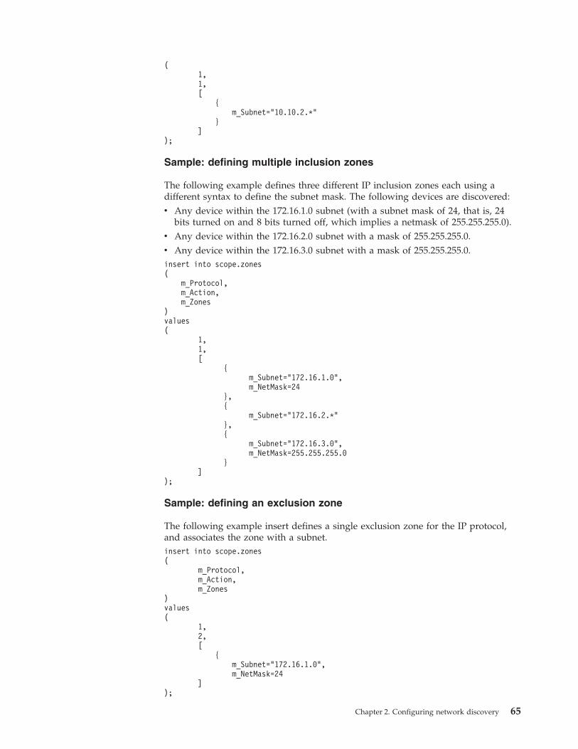
(1,1,[
{m_Subnet="10.10.2.*"
}]
);
Sample: defining multiple inclusion zones
The following example defines three different IP inclusion zones each using adifferent syntax to define the subnet mask. The following devices are discovered:v Any device within the 172.16.1.0 subnet (with a subnet mask of 24, that is, 24
bits turned on and 8 bits turned off, which implies a netmask of 255.255.255.0).v Any device within the 172.16.2.0 subnet with a mask of 255.255.255.0.v Any device within the 172.16.3.0 subnet with a mask of 255.255.255.0.insert into scope.zones(
m_Protocol,m_Action,m_Zones
)values(
1,1,[
{m_Subnet="172.16.1.0",m_NetMask=24
},{
m_Subnet="172.16.2.*"},{
m_Subnet="172.16.3.0",m_NetMask=255.255.255.0
}]
);
Sample: defining an exclusion zone
The following example insert defines a single exclusion zone for the IP protocol,and associates the zone with a subnet.insert into scope.zones(
m_Protocol,m_Action,m_Zones
)values(
1,2,[
{m_Subnet="172.16.1.0",m_NetMask=24
]);
Chapter 2. Configuring network discovery 65
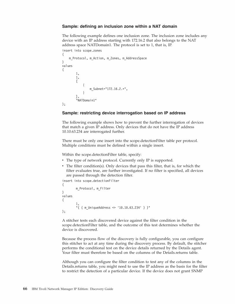
Sample: defining an inclusion zone within a NAT domain
The following example defines one inclusion zone. The inclusion zone includes anydevice with an IP address starting with 172.16.2 that also belongs to the NATaddress space NATDomain1. The protocol is set to 1, that is, IP.insert into scope.zones(
m_Protocol, m_Action, m_Zones, m_AddressSpace)values(
1,1,[
{m_Subnet="172.16.2.*",
}],"NATDomain1"
);
Sample: restricting device interrogation based on IP address
The following example shows how to prevent the further interrogation of devicesthat match a given IP address. Only devices that do not have the IP address10.10.63.234 are interrogated further.
There must be only one insert into the scope.detectionFilter table per protocol.Multiple conditions must be defined within a single insert.
Within the scope.detectionFilter table, specify:v The type of network protocol. Currently only IP is supported.v The filter condition(s). Only devices that pass this filter, that is, for which the
filter evaluates true, are further investigated. If no filter is specified, all devicesare passed through the detection filter.
insert into scope.detectionFilter(
m_Protocol, m_Filter)values(
1,"( ( m_UniqueAddress <> ’10.10.63.234’ ) )"
);
A stitcher tests each discovered device against the filter condition in thescope.detectionFilter table, and the outcome of this test determines whether thedevice is discovered.
Because the process flow of the discovery is fully configurable, you can configurethis stitcher to act at any time during the discovery process. By default, the stitcherperforms the conditional test on the device details returned by the Details agent.Your filter must therefore be based on the columns of the Details.returns table.
Although you can configure the filter condition to test any of the columns in theDetails.returns table, you might need to use the IP address as the basis for the filterto restrict the detection of a particular device. If the device does not grant SNMP
66 IBM Tivoli Network Manager IP Edition: Discovery Guide
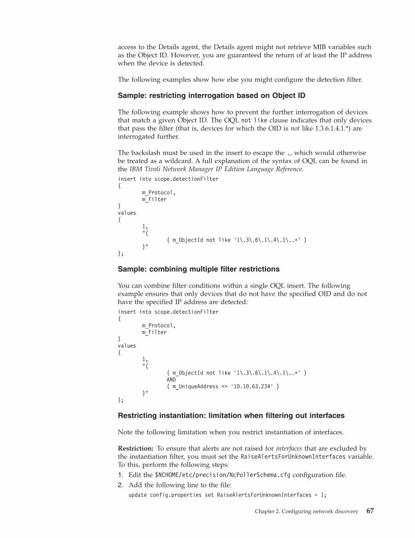
access to the Details agent, the Details agent might not retrieve MIB variables suchas the Object ID. However, you are guaranteed the return of at least the IP addresswhen the device is detected.
The following examples show how else you might configure the detection filter.
Sample: restricting interrogation based on Object ID
The following example shows how to prevent the further interrogation of devicesthat match a given Object ID. The OQL not like clause indicates that only devicesthat pass the filter (that is, devices for which the OID is not like 1.3.6.1.4.1.*) areinterrogated further.
The backslash must be used in the insert to escape the ., which would otherwisebe treated as a wildcard. A full explanation of the syntax of OQL can be found inthe IBM Tivoli Network Manager IP Edition Language Reference.insert into scope.detectionFilter(
m_Protocol,m_Filter
)values(
1,"(
( m_ObjectId not like ’1\.3\.6\.1\.4\.1\..*’ ))"
);
Sample: combining multiple filter restrictions
You can combine filter conditions within a single OQL insert. The followingexample ensures that only devices that do not have the specified OID and do nothave the specified IP address are detected:insert into scope.detectionFilter(
m_Protocol,m_Filter
)values(
1,"(
( m_ObjectId not like ’1\.3\.6\.1\.4\.1\..*’ )AND( m_UniqueAddress <> ’10.10.63.234’ )
)");
Restricting instantiation: limitation when filtering out interfaces
Note the following limitation when you restrict instantiation of interfaces.
Restriction: To ensure that alerts are not raised for interfaces that are excluded bythe instantiation filter, you must set the RaiseAlertsForUnknownInterfaces variable.To this, perform the following steps:1. Edit the $NCHOME/etc/precision/NcPollerSchema.cfg configuration file.2. Add the following line to the file:
update config.properties set RaiseAlertsForUnknownInterfaces = 1;
Chapter 2. Configuring network discovery 67
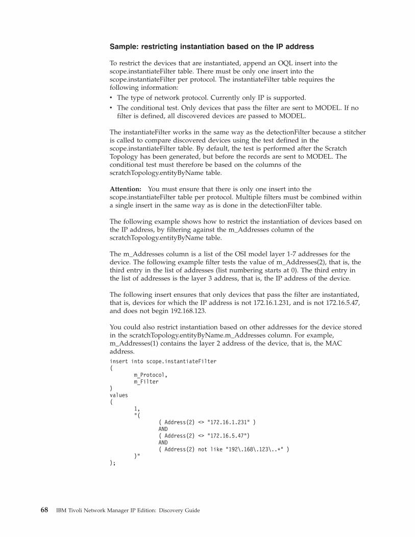
Sample: restricting instantiation based on the IP address
To restrict the devices that are instantiated, append an OQL insert into thescope.instantiateFilter table. There must be only one insert into thescope.instantiateFilter per protocol. The instantiateFilter table requires thefollowing information:v The type of network protocol. Currently only IP is supported.v The conditional test. Only devices that pass the filter are sent to MODEL. If no
filter is defined, all discovered devices are passed to MODEL.
The instantiateFilter works in the same way as the detectionFilter because a stitcheris called to compare discovered devices using the test defined in thescope.instantiateFilter table. By default, the test is performed after the ScratchTopology has been generated, but before the records are sent to MODEL. Theconditional test must therefore be based on the columns of thescratchTopology.entityByName table.
Attention: You must ensure that there is only one insert into thescope.instantiateFilter table per protocol. Multiple filters must be combined withina single insert in the same way as is done in the detectionFilter table.
The following example shows how to restrict the instantiation of devices based onthe IP address, by filtering against the m_Addresses column of thescratchTopology.entityByName table.
The m_Addresses column is a list of the OSI model layer 1-7 addresses for thedevice. The following example filter tests the value of m_Addresses(2), that is, thethird entry in the list of addresses (list numbering starts at 0). The third entry inthe list of addresses is the layer 3 address, that is, the IP address of the device.
The following insert ensures that only devices that pass the filter are instantiated,that is, devices for which the IP address is not 172.16.1.231, and is not 172.16.5.47,and does not begin 192.168.123.
You could also restrict instantiation based on other addresses for the device storedin the scratchTopology.entityByName.m_Addresses column. For example,m_Addresses(1) contains the layer 2 address of the device, that is, the MACaddress.insert into scope.instantiateFilter(
m_Protocol,m_Filter
)values(
1,"(
( Address(2) <> "172.16.1.231" )AND( Address(2) <> "172.16.5.47")AND( Address(2) not like "192\.168\.123\..*" )
)");
68 IBM Tivoli Network Manager IP Edition: Discovery Guide
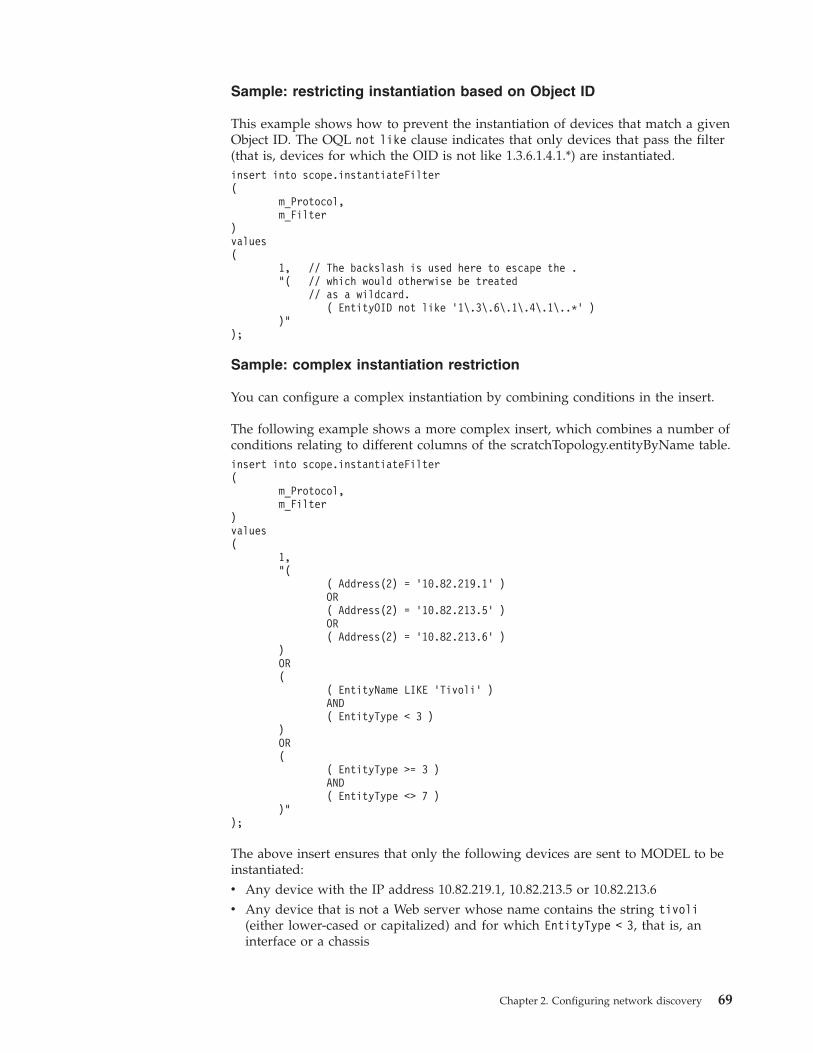
Sample: restricting instantiation based on Object ID
This example shows how to prevent the instantiation of devices that match a givenObject ID. The OQL not like clause indicates that only devices that pass the filter(that is, devices for which the OID is not like 1.3.6.1.4.1.*) are instantiated.insert into scope.instantiateFilter(
m_Protocol,m_Filter
)values(
1, // The backslash is used here to escape the ."( // which would otherwise be treated
// as a wildcard.( EntityOID not like ’1\.3\.6\.1\.4\.1\..*’ )
)");
Sample: complex instantiation restriction
You can configure a complex instantiation by combining conditions in the insert.
The following example shows a more complex insert, which combines a number ofconditions relating to different columns of the scratchTopology.entityByName table.insert into scope.instantiateFilter(
m_Protocol,m_Filter
)values(
1,"(
( Address(2) = ’10.82.219.1’ )OR( Address(2) = ’10.82.213.5’ )OR( Address(2) = ’10.82.213.6’ )
)OR(
( EntityName LIKE ’Tivoli’ )AND( EntityType < 3 )
)OR(
( EntityType >= 3 )AND( EntityType <> 7 )
)");
The above insert ensures that only the following devices are sent to MODEL to beinstantiated:v Any device with the IP address 10.82.219.1, 10.82.213.5 or 10.82.213.6v Any device that is not a Web server whose name contains the string tivoli
(either lower-cased or capitalized) and for which EntityType < 3, that is, aninterface or a chassis
Chapter 2. Configuring network discovery 69
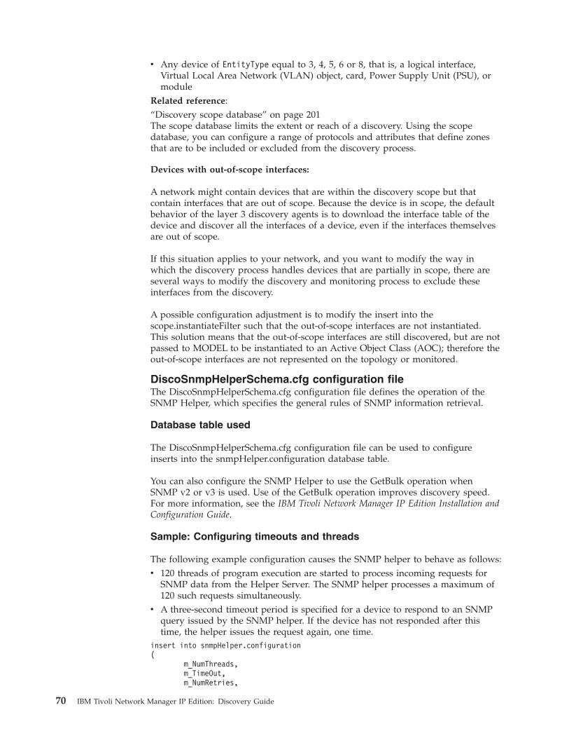
v Any device of EntityType equal to 3, 4, 5, 6 or 8, that is, a logical interface,Virtual Local Area Network (VLAN) object, card, Power Supply Unit (PSU), ormodule
Related reference:“Discovery scope database” on page 201The scope database limits the extent or reach of a discovery. Using the scopedatabase, you can configure a range of protocols and attributes that define zonesthat are to be included or excluded from the discovery process.
Devices with out-of-scope interfaces:
A network might contain devices that are within the discovery scope but thatcontain interfaces that are out of scope. Because the device is in scope, the defaultbehavior of the layer 3 discovery agents is to download the interface table of thedevice and discover all the interfaces of a device, even if the interfaces themselvesare out of scope.
If this situation applies to your network, and you want to modify the way inwhich the discovery process handles devices that are partially in scope, there areseveral ways to modify the discovery and monitoring process to exclude theseinterfaces from the discovery.
A possible configuration adjustment is to modify the insert into thescope.instantiateFilter such that the out-of-scope interfaces are not instantiated.This solution means that the out-of-scope interfaces are still discovered, but are notpassed to MODEL to be instantiated to an Active Object Class (AOC); therefore theout-of-scope interfaces are not represented on the topology or monitored.
DiscoSnmpHelperSchema.cfg configuration fileThe DiscoSnmpHelperSchema.cfg configuration file defines the operation of theSNMP Helper, which specifies the general rules of SNMP information retrieval.
Database table used
The DiscoSnmpHelperSchema.cfg configuration file can be used to configureinserts into the snmpHelper.configuration database table.
You can also configure the SNMP Helper to use the GetBulk operation whenSNMP v2 or v3 is used. Use of the GetBulk operation improves discovery speed.For more information, see the IBM Tivoli Network Manager IP Edition Installation andConfiguration Guide.
Sample: Configuring timeouts and threads
The following example configuration causes the SNMP helper to behave as follows:v 120 threads of program execution are started to process incoming requests for
SNMP data from the Helper Server. The SNMP helper processes a maximum of120 such requests simultaneously.
v A three-second timeout period is specified for a device to respond to an SNMPquery issued by the SNMP helper. If the device has not responded after thistime, the helper issues the request again, one time.
insert into snmpHelper.configuration(
m_NumThreads,m_TimeOut,m_NumRetries,
70 IBM Tivoli Network Manager IP Edition: Discovery Guide
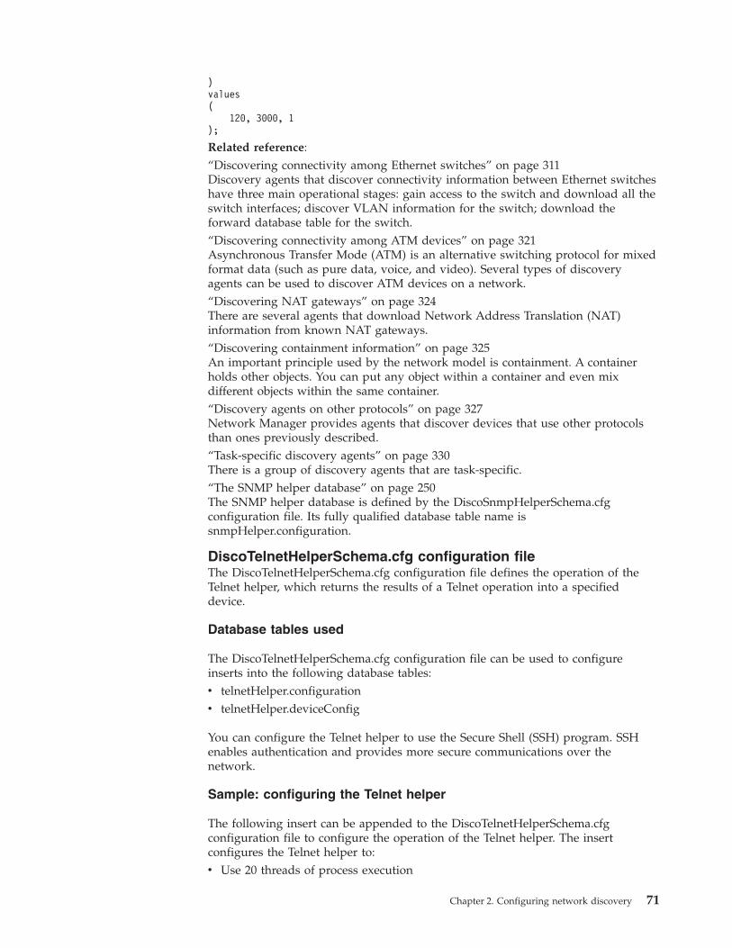
)values(
120, 3000, 1);
Related reference:“Discovering connectivity among Ethernet switches” on page 311Discovery agents that discover connectivity information between Ethernet switcheshave three main operational stages: gain access to the switch and download all theswitch interfaces; discover VLAN information for the switch; download theforward database table for the switch.“Discovering connectivity among ATM devices” on page 321Asynchronous Transfer Mode (ATM) is an alternative switching protocol for mixedformat data (such as pure data, voice, and video). Several types of discoveryagents can be used to discover ATM devices on a network.“Discovering NAT gateways” on page 324There are several agents that download Network Address Translation (NAT)information from known NAT gateways.“Discovering containment information” on page 325An important principle used by the network model is containment. A containerholds other objects. You can put any object within a container and even mixdifferent objects within the same container.“Discovery agents on other protocols” on page 327Network Manager provides agents that discover devices that use other protocolsthan ones previously described.“Task-specific discovery agents” on page 330There is a group of discovery agents that are task-specific.“The SNMP helper database” on page 250The SNMP helper database is defined by the DiscoSnmpHelperSchema.cfgconfiguration file. Its fully qualified database table name issnmpHelper.configuration.
DiscoTelnetHelperSchema.cfg configuration fileThe DiscoTelnetHelperSchema.cfg configuration file defines the operation of theTelnet helper, which returns the results of a Telnet operation into a specifieddevice.
Database tables used
The DiscoTelnetHelperSchema.cfg configuration file can be used to configureinserts into the following database tables:v telnetHelper.configurationv telnetHelper.deviceConfig
You can configure the Telnet helper to use the Secure Shell (SSH) program. SSHenables authentication and provides more secure communications over thenetwork.
Sample: configuring the Telnet helper
The following insert can be appended to the DiscoTelnetHelperSchema.cfgconfiguration file to configure the operation of the Telnet helper. The insertconfigures the Telnet helper to:v Use 20 threads of process execution
Chapter 2. Configuring network discovery 71
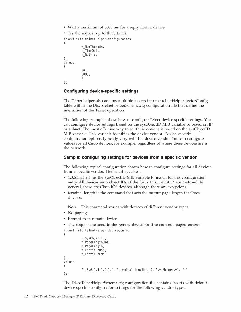
v Wait a maximum of 5000 ms for a reply from a devicev Try the request up to three timesinsert into telnetHelper.configuration(
m_NumThreads,m_TimeOut,m_Retries
)values(
20,5000,3
);
Configuring device-specific settings
The Telnet helper also accepts multiple inserts into the telnetHelper.deviceConfigtable within the DiscoTelnetHelperSchema.cfg configuration file that define theinteraction of the Telnet operation.
The following examples show how to configure Telnet device-specific settings. Youcan configure device settings based on the sysObjectID MIB variable or based on IPor subnet. The most effective way to set these options is based on the sysObjectIDMIB variable. This variable identifies the device vendor. Device-specificconfiguration options typically vary with the device vendor. You can configurevalues for all Cisco devices, for example, regardless of where these devices are inthe network.
Sample: configuring settings for devices from a specific vendor
The following typical configuration shows how to configure settings for all devicesfrom a specific vendor. The insert specifies:v 1.3.6.1.4.1.9.1. as the sysObjectID MIB variable to match for this configuration
entry. All devices with object IDs of the form 1.3.6.1.4.1.9.1.* are matched. Ingeneral, these are Cisco IOS devices, although there are exceptions.
v terminal length is the command that sets the output page length for Ciscodevices.
Note: This command varies with devices of different vendor types.v No pagingv Prompt from remote devicev The response to send to the remote device for it to continue paged output.insert into telnetHelper.deviceConfig(
m_SysObjectId,m_PageLengthCmd,m_PageLength,m_ContinueMsg,m_ContinueCmd
)values(
"1.3.6.1.4.1.9.1.", "terminal length", 0, ".*[Mm]ore.*", " ");
The DiscoTelnetHelperSchema.cfg configuration file contains inserts with defaultdevice-specific configuration settings for the following vendor types:
72 IBM Tivoli Network Manager IP Edition: Discovery Guide
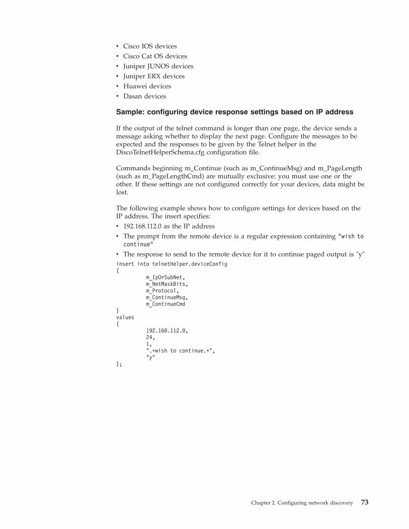
v Cisco IOS devicesv Cisco Cat OS devicesv Juniper JUNOS devicesv Juniper ERX devicesv Huawei devicesv Dasan devices
Sample: configuring device response settings based on IP address
If the output of the telnet command is longer than one page, the device sends amessage asking whether to display the next page. Configure the messages to beexpected and the responses to be given by the Telnet helper in theDiscoTelnetHelperSchema.cfg configuration file.
Commands beginning m_Continue (such as m_ContinueMsg) and m_PageLength(such as m_PageLengthCmd) are mutually exclusive: you must use one or theother. If these settings are not configured correctly for your devices, data might belost.
The following example shows how to configure settings for devices based on theIP address. The insert specifies:v 192.168.112.0 as the IP addressv The prompt from the remote device is a regular expression containing "wish to
continue"
v The response to send to the remote device for it to continue paged output is "y"insert into telnetHelper.deviceConfig(
m_IpOrSubNet,m_NetMaskBits,m_Protocol,m_ContinueMsg,m_ContinueCmd
)values(
192.168.112.0,24,1,".*wish to continue.*","y"
);
Chapter 2. Configuring network discovery 73
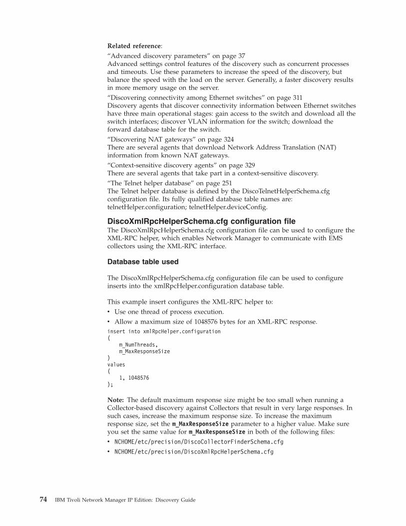
Related reference:“Advanced discovery parameters” on page 37Advanced settings control features of the discovery such as concurrent processesand timeouts. Use these parameters to increase the speed of the discovery, butbalance the speed with the load on the server. Generally, a faster discovery resultsin more memory usage on the server.“Discovering connectivity among Ethernet switches” on page 311Discovery agents that discover connectivity information between Ethernet switcheshave three main operational stages: gain access to the switch and download all theswitch interfaces; discover VLAN information for the switch; download theforward database table for the switch.“Discovering NAT gateways” on page 324There are several agents that download Network Address Translation (NAT)information from known NAT gateways.“Context-sensitive discovery agents” on page 329There are several agents that take part in a context-sensitive discovery.“The Telnet helper database” on page 251The Telnet helper database is defined by the DiscoTelnetHelperSchema.cfgconfiguration file. Its fully qualified database table names are:telnetHelper.configuration; telnetHelper.deviceConfig.
DiscoXmlRpcHelperSchema.cfg configuration fileThe DiscoXmlRpcHelperSchema.cfg configuration file can be used to configure theXML-RPC helper, which enables Network Manager to communicate with EMScollectors using the XML-RPC interface.
Database table used
The DiscoXmlRpcHelperSchema.cfg configuration file can be used to configureinserts into the xmlRpcHelper.configuration database table.
This example insert configures the XML-RPC helper to:v Use one thread of process execution.v Allow a maximum size of 1048576 bytes for an XML-RPC response.insert into xmlRpcHelper.configuration(
m_NumThreads,m_MaxResponseSize
)values(
1, 1048576);
Note: The default maximum response size might be too small when running aCollector-based discovery against Collectors that result in very large responses. Insuch cases, increase the maximum response size. To increase the maximumresponse size, set the m_MaxResponseSize parameter to a higher value. Make sureyou set the same value for m_MaxResponseSize in both of the following files:v NCHOME/etc/precision/DiscoCollectorFinderSchema.cfg
v NCHOME/etc/precision/DiscoXmlRpcHelperSchema.cfg
74 IBM Tivoli Network Manager IP Edition: Discovery Guide
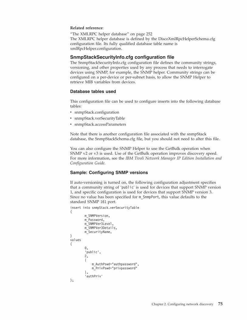
Related reference:“The XMLRPC helper database” on page 252The XMLRPC helper database is defined by the DiscoXmlRpcHelperSchema.cfgconfiguration file. Its fully qualified database table name isxmlRpcHelper.configuration.
SnmpStackSecurityInfo.cfg configuration fileThe SnmpStackSecurityInfo.cfg configuration file defines the community strings,versioning, and other properties used by any process that needs to interrogatedevices using SNMP, for example, the SNMP helper. Community strings can beconfigured on a per-device or per-subnet basis, to allow the SNMP Helper toretrieve MIB variables from devices.
Database tables used
This configuration file can be used to configure inserts into the following databasetables:v snmpStack.configurationv snmpStack.verSecurityTablev snmpStack.accessParameters
Note that there is another configuration file associated with the snmpStackdatabase, the SnmpStackSchema.cfg file, but you should not need to alter this file.
You can also configure the SNMP Helper to use the GetBulk operation whenSNMP v2 or v3 is used. Use of the GetBulk operation improves discovery speed.For more information, see the IBM Tivoli Network Manager IP Edition Installation andConfiguration Guide.
Sample: Configuring SNMP versions
If auto-versioning is turned on, the following configuration adjustment specifiesthat a community string of ‘public' is used for devices that support SNMP version1, and specific configuration is used for devices that support SNMP version 3.Since no value has been specified for m_SnmpPort, this value defaults to thestandard SNMP 161 port.insert into snmpStack.verSecurityTable(
m_SNMPVersion,m_Password,m_SNMPVer3Level,m_SNMPVer3Details,m_SecurityName,
)values(
0,’public’,2,{
m_AuthPswd="authpassword",m_PrivPswd="privpassword"
},’authPriv’
);
Chapter 2. Configuring network discovery 75
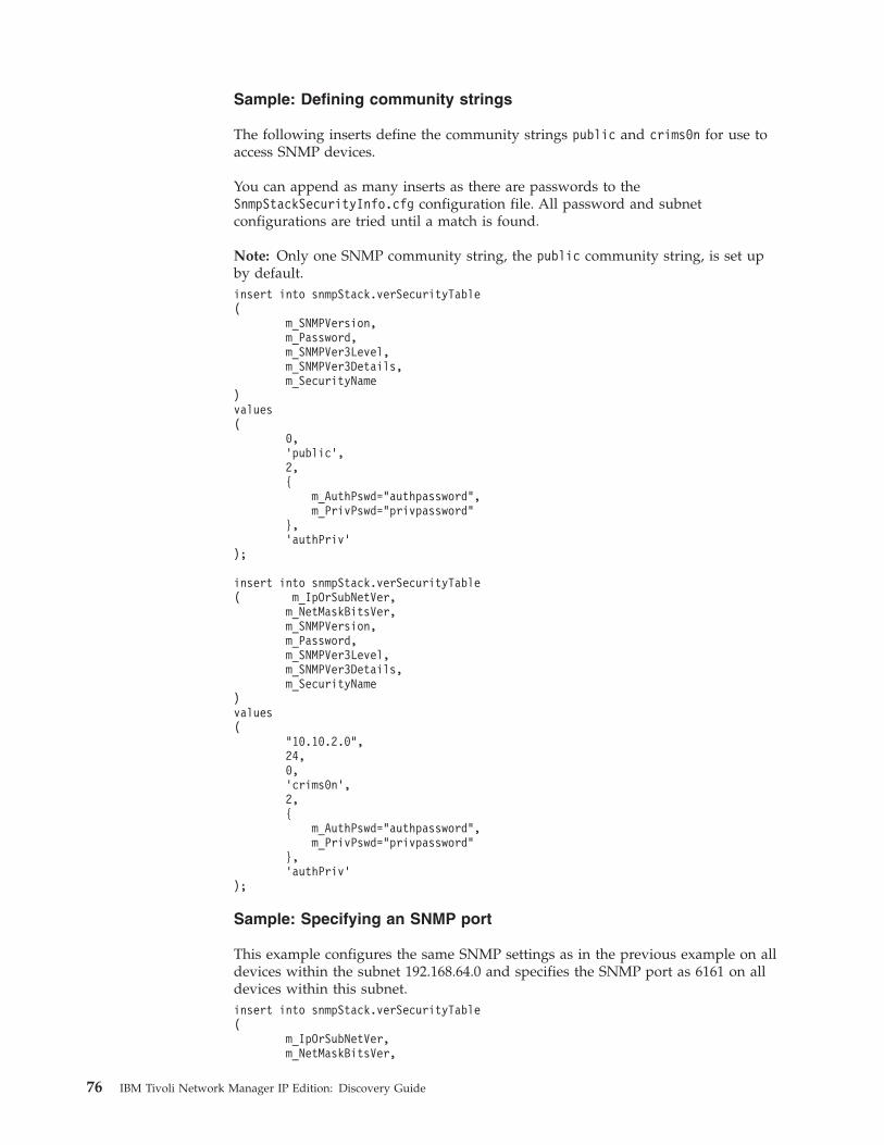
Sample: Defining community strings
The following inserts define the community strings public and crims0n for use toaccess SNMP devices.
You can append as many inserts as there are passwords to theSnmpStackSecurityInfo.cfg configuration file. All password and subnetconfigurations are tried until a match is found.
Note: Only one SNMP community string, the public community string, is set upby default.insert into snmpStack.verSecurityTable(
m_SNMPVersion,m_Password,m_SNMPVer3Level,m_SNMPVer3Details,m_SecurityName
)values(
0,’public’,2,{
m_AuthPswd="authpassword",m_PrivPswd="privpassword"
},’authPriv’
);
insert into snmpStack.verSecurityTable( m_IpOrSubNetVer,
m_NetMaskBitsVer,m_SNMPVersion,m_Password,m_SNMPVer3Level,m_SNMPVer3Details,m_SecurityName
)values(
"10.10.2.0",24,0,’crims0n’,2,{
m_AuthPswd="authpassword",m_PrivPswd="privpassword"
},’authPriv’
);
Sample: Specifying an SNMP port
This example configures the same SNMP settings as in the previous example on alldevices within the subnet 192.168.64.0 and specifies the SNMP port as 6161 on alldevices within this subnet.insert into snmpStack.verSecurityTable(
m_IpOrSubNetVer,m_NetMaskBitsVer,
76 IBM Tivoli Network Manager IP Edition: Discovery Guide
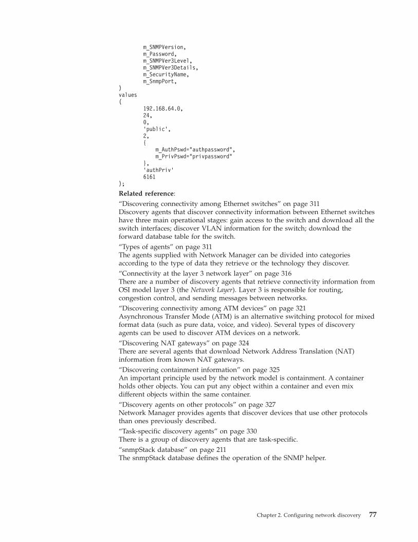
m_SNMPVersion,m_Password,m_SNMPVer3Level,m_SNMPVer3Details,m_SecurityName,m_SnmpPort,
)values(
192.168.64.0,24,0,’public’,2,{
m_AuthPswd="authpassword",m_PrivPswd="privpassword"
},’authPriv’6161
);
Related reference:“Discovering connectivity among Ethernet switches” on page 311Discovery agents that discover connectivity information between Ethernet switcheshave three main operational stages: gain access to the switch and download all theswitch interfaces; discover VLAN information for the switch; download theforward database table for the switch.“Types of agents” on page 311The agents supplied with Network Manager can be divided into categoriesaccording to the type of data they retrieve or the technology they discover.“Connectivity at the layer 3 network layer” on page 316There are a number of discovery agents that retrieve connectivity information fromOSI model layer 3 (the Network Layer). Layer 3 is responsible for routing,congestion control, and sending messages between networks.“Discovering connectivity among ATM devices” on page 321Asynchronous Transfer Mode (ATM) is an alternative switching protocol for mixedformat data (such as pure data, voice, and video). Several types of discoveryagents can be used to discover ATM devices on a network.“Discovering NAT gateways” on page 324There are several agents that download Network Address Translation (NAT)information from known NAT gateways.“Discovering containment information” on page 325An important principle used by the network model is containment. A containerholds other objects. You can put any object within a container and even mixdifferent objects within the same container.“Discovery agents on other protocols” on page 327Network Manager provides agents that discover devices that use other protocolsthan ones previously described.“Task-specific discovery agents” on page 330There is a group of discovery agents that are task-specific.“snmpStack database” on page 211The snmpStack database defines the operation of the SNMP helper.
Chapter 2. Configuring network discovery 77
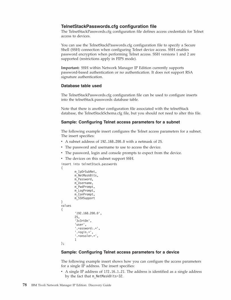
TelnetStackPasswords.cfg configuration fileThe TelnetStackPasswords.cfg configuration file defines access credentials for Telnetaccess to devices.
You can use the TelnetStackPasswords.cfg configuration file to specify a SecureShell (SSH) connection when configuring Telnet device access. SSH enablespassword encryption when performing Telnet access. SSH versions 1 and 2 aresupported (restrictions apply in FIPS mode).
Important: SSH within Network Manager IP Edition currently supportspassword-based authentication or no authentication. It does not support RSAsignature authentication.
Database table used
The TelnetStackPasswords.cfg configuration file can be used to configure insertsinto the telnetStack.passwords database table.
Note that there is another configuration file associated with the telnetStackdatabase, the TelnetStackSchema.cfg file, but you should not need to alter this file.
Sample: Configuring Telnet access parameters for a subnet
The following example insert configures the Telnet access parameters for a subnet.The insert specifies:v A subnet address of 192.168.200.0 with a netmask of 25.v The password and username to use to access the device.v The password, login and console prompts to expect from the device.v The devices on this subnet support SSH.insert into telnetStack.passwords(
m_IpOrSubNet,m_NetMaskBits,m_Password,m_Username,m_PwdPrompt,m_LogPrompt,m_ConPrompt,m_SSHSupport
)values(
’192.168.200.0’,25,’3v3rt0n’,’user’,’.*assword:.*’,’.*ogin.*’,’.*onsole>.*’,1
);
Sample: Configuring Telnet access parameters for a device
The following example insert shows how you can configure the access parametersfor a single IP address. The insert specifies:v A single IP address of 172.16.1.21. The address is identified as a single address
by the fact that m_NetMaskBits=32.
78 IBM Tivoli Network Manager IP Edition: Discovery Guide
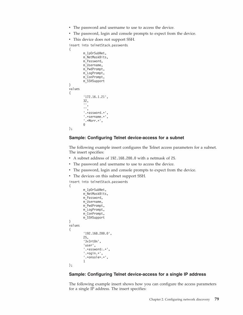
v The password and username to use to access the device.v The password, login and console prompts to expect from the device.v This device does not support SSH.insert into telnetStack.passwords(
m_IpOrSubNet,m_NetMaskBits,m_Password,m_Username,m_PwdPrompt,m_LogPrompt,m_ConPrompt,m_SSHSupport
)values(
’172.16.1.21’,32,’’,’’,’.*assword.*’,’.*sername.*’,’.*Morr.*’,0
);
Sample: Configuring Telnet device-access for a subnet
The following example insert configures the Telnet access parameters for a subnet.The insert specifies:v A subnet address of 192.168.200.0 with a netmask of 25.v The password and username to use to access the device.v The password, login and console prompts to expect from the device.v The devices on this subnet support SSH.insert into telnetStack.passwords(
m_IpOrSubNet,m_NetMaskBits,m_Password,m_Username,m_PwdPrompt,m_LogPrompt,m_ConPrompt,m_SSHSupport
)values(
’192.168.200.0’,25,’3v3rt0n’,’user’,’.*assword:.*’,’.*ogin.*’,’.*onsole>.*’,1
);
Sample: Configuring Telnet device-access for a single IP address
The following example insert shows how you can configure the access parametersfor a single IP address. The insert specifies:
Chapter 2. Configuring network discovery 79
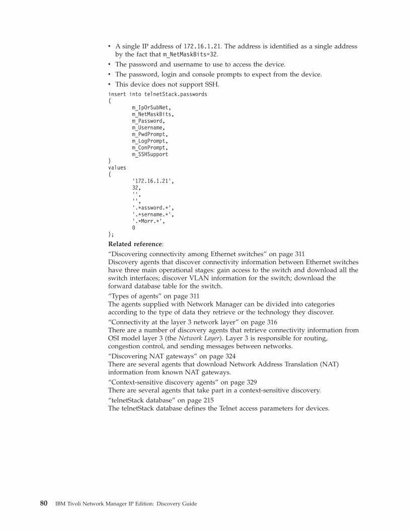
v A single IP address of 172.16.1.21. The address is identified as a single addressby the fact that m_NetMaskBits=32.
v The password and username to use to access the device.v The password, login and console prompts to expect from the device.v This device does not support SSH.insert into telnetStack.passwords(
m_IpOrSubNet,m_NetMaskBits,m_Password,m_Username,m_PwdPrompt,m_LogPrompt,m_ConPrompt,m_SSHSupport
)values(
’172.16.1.21’,32,’’,’’,’.*assword.*’,’.*sername.*’,’.*Morr.*’,0
);
Related reference:“Discovering connectivity among Ethernet switches” on page 311Discovery agents that discover connectivity information between Ethernet switcheshave three main operational stages: gain access to the switch and download all theswitch interfaces; discover VLAN information for the switch; download theforward database table for the switch.“Types of agents” on page 311The agents supplied with Network Manager can be divided into categoriesaccording to the type of data they retrieve or the technology they discover.“Connectivity at the layer 3 network layer” on page 316There are a number of discovery agents that retrieve connectivity information fromOSI model layer 3 (the Network Layer). Layer 3 is responsible for routing,congestion control, and sending messages between networks.“Discovering NAT gateways” on page 324There are several agents that download Network Address Translation (NAT)information from known NAT gateways.“Context-sensitive discovery agents” on page 329There are several agents that take part in a context-sensitive discovery.“telnetStack database” on page 215The telnetStack database defines the Telnet access parameters for devices.
80 IBM Tivoli Network Manager IP Edition: Discovery Guide
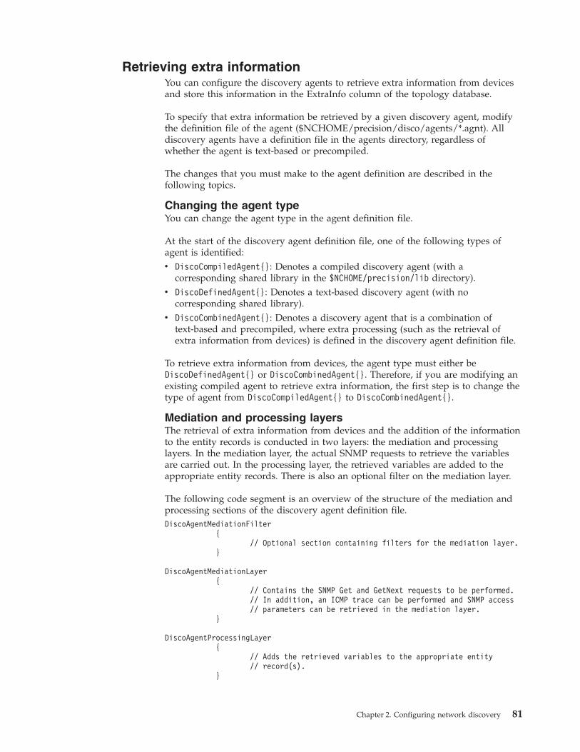
Retrieving extra informationYou can configure the discovery agents to retrieve extra information from devicesand store this information in the ExtraInfo column of the topology database.
To specify that extra information be retrieved by a given discovery agent, modifythe definition file of the agent ($NCHOME/precision/disco/agents/*.agnt). Alldiscovery agents have a definition file in the agents directory, regardless ofwhether the agent is text-based or precompiled.
The changes that you must make to the agent definition are described in thefollowing topics.
Changing the agent typeYou can change the agent type in the agent definition file.
At the start of the discovery agent definition file, one of the following types ofagent is identified:v DiscoCompiledAgent{}: Denotes a compiled discovery agent (with a
corresponding shared library in the $NCHOME/precision/lib directory).v DiscoDefinedAgent{}: Denotes a text-based discovery agent (with no
corresponding shared library).v DiscoCombinedAgent{}: Denotes a discovery agent that is a combination of
text-based and precompiled, where extra processing (such as the retrieval ofextra information from devices) is defined in the discovery agent definition file.
To retrieve extra information from devices, the agent type must either beDiscoDefinedAgent{} or DiscoCombinedAgent{}. Therefore, if you are modifying anexisting compiled agent to retrieve extra information, the first step is to change thetype of agent from DiscoCompiledAgent{} to DiscoCombinedAgent{}.
Mediation and processing layersThe retrieval of extra information from devices and the addition of the informationto the entity records is conducted in two layers: the mediation and processinglayers. In the mediation layer, the actual SNMP requests to retrieve the variablesare carried out. In the processing layer, the retrieved variables are added to theappropriate entity records. There is also an optional filter on the mediation layer.
The following code segment is an overview of the structure of the mediation andprocessing sections of the discovery agent definition file.DiscoAgentMediationFilter
{// Optional section containing filters for the mediation layer.
}
DiscoAgentMediationLayer{
// Contains the SNMP Get and GetNext requests to be performed.// In addition, an ICMP trace can be performed and SNMP access// parameters can be retrieved in the mediation layer.
}
DiscoAgentProcessingLayer{
// Adds the retrieved variables to the appropriate entity// record(s).
}
Chapter 2. Configuring network discovery 81
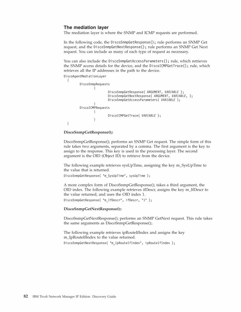
The mediation layerThe mediation layer is where the SNMP and ICMP requests are performed.
In the following code, the DiscoSnmpGetResponse(); rule performs an SNMP Getrequest, and the DiscoSnmpGetNextResponse(); rule performs an SNMP Get Nextrequest. You can include as many of each type of request as necessary.
You can also include the DiscoSnmpGetAccessParameters(); rule, which retrievesthe SNMP access details for the device, and the DiscoICMPGetTrace(); rule, whichretrieves all the IP addresses in the path to the device.DiscoAgentMediationLayer
{DiscoSnmpRequests
{DiscoSnmpGetResponse( ARGUMENT, VARIABLE );DiscoSnmpGetNextResponse( ARGUMENT, VARIABLE, );DiscoSnmpGetAccessParameters( VARIABLE );
}DiscoICMPRequests
{DiscoICMPGetTrace( VARIABLE );
}}
DiscoSnmpGetResponse();:
DiscoSnmpGetResponse(); performs an SNMP Get request. The simple form of thisrule takes two arguments, separated by a comma. The first argument is the key toassign to the response. This key is used in the processing layer. The secondargument is the OID (Object ID) to retrieve from the device.
The following example retrieves sysUpTime, assigning the key m_SysUpTime tothe value that is returned.DiscoSnmpGetResponse( "m_SysUpTime", sysUpTime );
A more complex form of DiscoSnmpGetResponse(); takes a third argument, theOID index. The following example retrieves ifDescr, assigns the key m_IfDescr tothe value returned, and uses the OID index 1.DiscoSnmpGetResponse( "m_IfDescr", ifDescr, "1" );
DiscoSnmpGetNextResponse();:
DiscoSnmpGetNextResponse(); performs an SNMP GetNext request. This rule takesthe same arguments as DiscoSnmpGetResponse();.
The following example retrieves ipRouteIfIndex and assigns the keym_IpRouteIfIndex to the value returned.DiscoSnmpGetNextResponse( "m_IpRouteIfIndex", ipRouteIfIndex );
82 IBM Tivoli Network Manager IP Edition: Discovery Guide
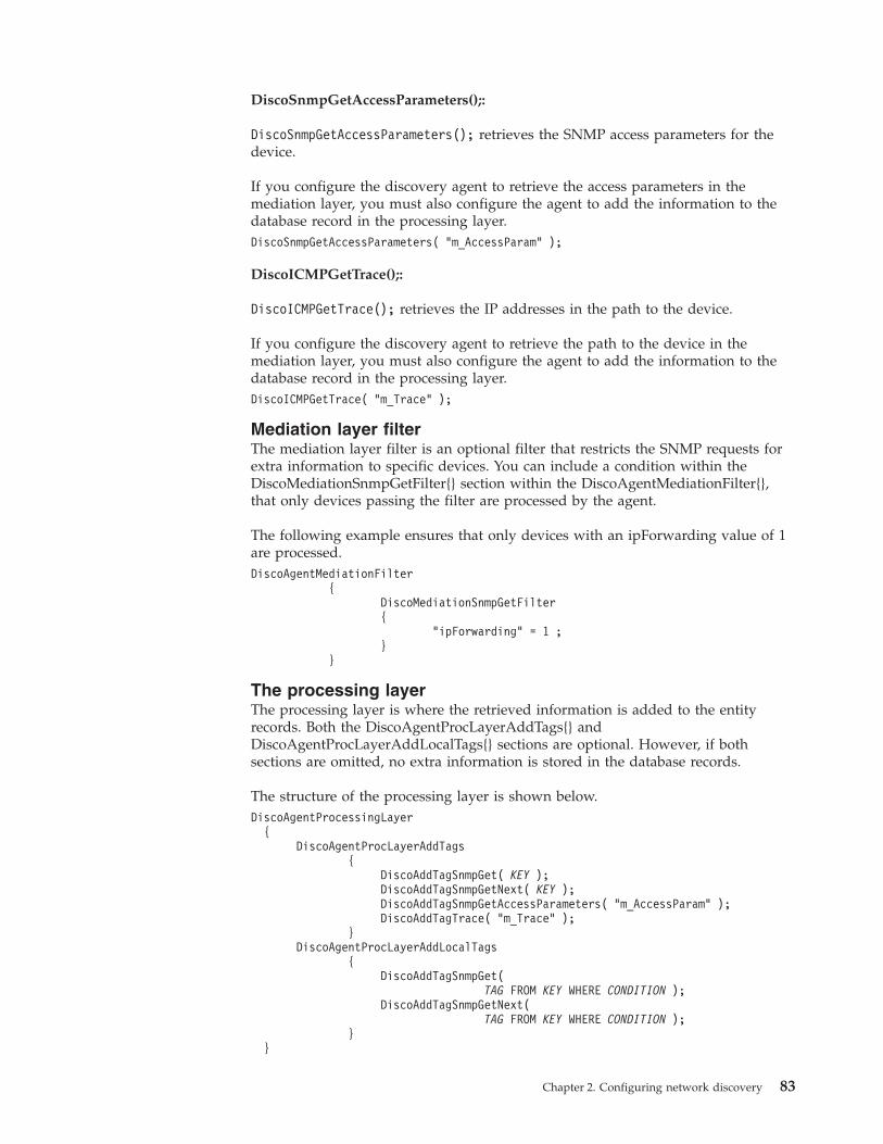
DiscoSnmpGetAccessParameters();:
DiscoSnmpGetAccessParameters(); retrieves the SNMP access parameters for thedevice.
If you configure the discovery agent to retrieve the access parameters in themediation layer, you must also configure the agent to add the information to thedatabase record in the processing layer.DiscoSnmpGetAccessParameters( "m_AccessParam" );
DiscoICMPGetTrace();:
DiscoICMPGetTrace(); retrieves the IP addresses in the path to the device.
If you configure the discovery agent to retrieve the path to the device in themediation layer, you must also configure the agent to add the information to thedatabase record in the processing layer.DiscoICMPGetTrace( "m_Trace" );
Mediation layer filterThe mediation layer filter is an optional filter that restricts the SNMP requests forextra information to specific devices. You can include a condition within theDiscoMediationSnmpGetFilter{} section within the DiscoAgentMediationFilter{},that only devices passing the filter are processed by the agent.
The following example ensures that only devices with an ipForwarding value of 1are processed.DiscoAgentMediationFilter
{DiscoMediationSnmpGetFilter{
"ipForwarding" = 1 ;}
}
The processing layerThe processing layer is where the retrieved information is added to the entityrecords. Both the DiscoAgentProcLayerAddTags{} andDiscoAgentProcLayerAddLocalTags{} sections are optional. However, if bothsections are omitted, no extra information is stored in the database records.
The structure of the processing layer is shown below.DiscoAgentProcessingLayer
{DiscoAgentProcLayerAddTags
{DiscoAddTagSnmpGet( KEY );DiscoAddTagSnmpGetNext( KEY );DiscoAddTagSnmpGetAccessParameters( "m_AccessParam" );DiscoAddTagTrace( "m_Trace" );
}DiscoAgentProcLayerAddLocalTags
{DiscoAddTagSnmpGet(
TAG FROM KEY WHERE CONDITION );DiscoAddTagSnmpGetNext(
TAG FROM KEY WHERE CONDITION );}
}
Chapter 2. Configuring network discovery 83
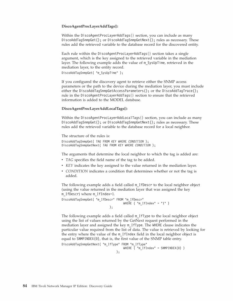
DiscoAgentProcLayerAddTags{}:
Within the DiscoAgentProcLayerAddTags{} section, you can include as manyDiscoAddTagSnmpGet(); or DiscoAddTagSnmpGetNext(); rules as necessary. Theserules add the retrieved variable to the database record for the discovered entity.
Each rule within the DiscoAgentProcLayerAddTags{} section takes a singleargument, which is the key assigned to the retrieved variable in the mediationlayer. The following example adds the value of m_SysUpTime, retrieved in themediation layer, to the entity record.DiscoAddTagSnmpGet( "m_SysUpTime" );
If you configured the discovery agent to retrieve either the SNMP accessparameters or the path to the device during the mediation layer, you must includeeither the DiscoAddTagSnmpGetAccessParameters(); or the DiscoAddTagTrace();rule in the DiscoAgentProcLayerAddTags{} section to ensure that the retrievedinformation is added to the MODEL database.
DiscoAgentProcLayerAddLocalTags{}:
Within the DiscoAgentProcLayerAddLocalTags{} section, you can include as manyDiscoAddTagSnmpGet(); or DiscoAddTagSnmpGetNext(); rules as necessary. Theserules add the retrieved variable to the database record for a local neighbor.
The structure of the rules is:DiscoAddTagSnmpGet( TAG FROM KEY WHERE CONDITION );DiscoAddTagSnmpGetNext( TAG FROM KEY WHERE CONDITION );
The arguments that determine the local neighbor to which the tag is added are:v TAG specifies the field name of the tag to be added.v KEY indicates the key assigned to the value returned in the mediation layer.v CONDITION indicates a condition that determines whether or not the tag is
added.
The following example adds a field called m_IfDescr to the local neighbor object(using the value returned in the mediation layer that was assigned the keym_IfDescr) where m_IfIndex=1.DiscoAddTagSnmpGet( "m_IfDescr" FROM "m_IfDescr"
WHERE ( "m_IfIndex" = "1" ));
The following example adds a field called m_IfType to the local neighbor objectusing the list of values returned by the GetNext request performed in themediation layer and assigned the key m_IfType. The WHERE clause indicates theparticular value required from the list of data. The value is retrieved by looking forthe entry where the value of the m_IfIndex field in the local neighbor object isequal to SNMPINDEX(0), that is, the first value of the SNMP table entry.DiscoAddTagSnmpGetNext( "m_IfType" FROM "m_IfType"
WHERE ( "m_IfIndex" = SNMPINDEX(0) ));
84 IBM Tivoli Network Manager IP Edition: Discovery Guide
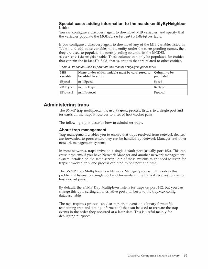
Special case: adding information to the master.entityByNeighbortableYou can configure a discovery agent to download MIB variables, and specify thatthe variables populate the MODEL master.entityByNeighbor table.
If you configure a discovery agent to download any of the MIB variables listed inTable 4 and add those variables to the entity under the corresponding names, thenthey are used to populate the corresponding columns in the MODELmaster.entityByNeighbor table. These columns can only be populated for entitiesthat contain the RelatedTo field, that is, entities that are related to other entities.
Table 4. Variables used to populate the master.entityByNeighbor table
MIBvariable
Name under which variable must be configured tobe added to entity
Column to bepopulated
ifSpeed m_IfSpeed Speed
ifRelType m_IfRelType RelType
ifProtocol m_IfProtocol Protocol
Administering trapsThe SNMP trap multiplexer, the ncp_trapmux process, listens to a single port andforwards all the traps it receives to a set of host/socket pairs.
The following topics describe how to administer traps.
About trap managementTrap management enables you to ensure that traps received from network devicesare forwarded to ports where they can be handled by Network Manager and othernetwork management systems.
In most networks, traps arrive on a single default port (usually port 162). This cancause problems if you have Network Manager and another network managementsystem installed on the same server. Both of these systems might need to listen fortraps; however, only one process can bind to one port at a time.
The SNMP Trap Multiplexer is a Network Manager process that resolves thisproblem: it listens to a single port and forwards all the traps it receives to a set ofhost/socket pairs.
By default, the SNMP Trap Multiplexer listens for traps on port 162, but you canchange this by inserting an alternative port number into the trapMux.configdatabase table.
The ncp_trapmux process can also store trap events in a binary format file(containing trap and timing information) that can be used to recreate the trapevents in the order they occurred at a later date. This is useful mainly fordebugging purposes.
Chapter 2. Configuring network discovery 85
Starting the SNMP trap multiplexerAlthough it is good practice to ensure that the ncp_ctrl process is configured tolaunch and manage the SNMP Trap Multiplexer, you can also start it manually.
To start the ncp_trapmux process, use the following command:ncp_trapmux -domain DOMAIN_NAME
Forwarding trapsUsing the SNMP Trap Multiplexer, you can forward traps to one or more servers.
To configure the SNMP Trap Multiplexer to forward traps to network managementsystems running on host1 and host2:1. Edit the schema file, $NCHOME/etc/precision/TrapMuxSchema.cfg, to contain a
set of host/socket pairs. For example, append the following lines to the file:insert into trapmux.sinkHosts (host, port) values ("host1", 5999);insert into trapmux.sinkHosts (host, port) values ("host2", 5999);
2. Start the SNMP Trap Multiplexer using the following commands:ncp_trapmux -domain DOMAIN1ncp_trapmux -domain DOMAIN2
In the above example, when a trap is sent to the server that is running thencp_trapmux process, it is forwarded to test-host1, port 5999 and test-host2, port5999.
Starting trap capture:
You can start capturing traps by inserting commands into the SNMP TrapMultiplexer database.
To instruct the SNMP Trap Multiplexer to start capturing traps:1. Log into the TrapMux service using the OQL Service Provider or the
Management Database Access page.2. Issue the following commands:
insert into trapMux.command(command) values( "capture_start" );go
Stopping trap capture:
You can stop capturing traps by inserting commands into the SNMP TrapMultiplexer database.
To instruct the SNMP Trap Multiplexer to stop capturing traps:1. Log into the TrapMux service using the OQL Service Provider or the
Management Database Access page.2. Issue the following commands:
insert into trapMux.command(command) values( "capture_stop" );go
86 IBM Tivoli Network Manager IP Edition: Discovery Guide
Printing traps to a file:
You can print traps to a file by inserting commands into the SNMP TrapMultiplexer database.
To instruct ncp_trapmux to print traps:1. Log into the TrapMux service using the OQL Service Provider or the
Management Database Access page.2. Issue the following commands:
insert into trapMux.command(command, fileName) values( "print", FILENAME );go
Where FILENAME specifies the file to which the output is written. If the file is notspecified, $NCHOME/etc/precision/trapmux.out is used.
Replaying traps from a file:
If you have created a text-readable file for traps, you can use the ncp_trapmuxprocess to recreate the trap events in the order specified in this file.
The ncp_trapmux process can replay traps using a binary file or a human-readablefile, however, the ncp_trapmux process can only generate binary files.
To instruct ncp_trapmux to replay traps from a file:1. Log into the TrapMux service using the OQL Service Provider or the
Management Database Access page.2. Issue the following commands:
insert into trapMux.command(command, fileName) values( "replay", "trapmux.out" );go
SNMP trap multiplexer commandsYou can issue commands to the SNMP trap multiplexer, the ncp_trapmux process,to control its operation.
The commands used to control the ncp_trapmux process are described in thefollowing table:
Table 5. Commands used to control the ncp_trapmux process
Command Function and Default Filename
capture_start Begin logging traps to memory. The default filename is NULL (notrequired).
capture_stop Stop logging traps to memory. The default filename is NULL (notrequired).
capture_continue Continue logging traps to memory. The default filename is NULL(not required).
capture_empty Clear memory of all currently logged traps. The default filename isNULL (not required).
rehash Shut down the ncp_trapmux process and clear all memory. Thedaemon then rereads the configuration file and starts up again.The default filename is NULL (not required).
restart Set the daemon to normal mode. The default filename is NULL(not required).
Chapter 2. Configuring network discovery 87
Table 5. Commands used to control the ncp_trapmux process (continued)
Command Function and Default Filename
replay Either read the traps in memory or read the raw trap packetinformation in the specified file and replay the traps with a smalldelay between each. The default filename is NULL (play frommemory).
replay timed Either read the traps in memory or read the raw trap packetinformation in the specified file and replay the traps in the orderof the time they were received with the same delays betweentraps. The default filename is NULL (play from memory).
print Print the current traps in memory in a non-readable format to thespecified file. Time information is encoded with the trap. Thedefault filename is $NCHOME/etc/precision/trapmux.out.
Configuring specialized discoveriesYou can configure the system to perform more complex discoveries, such as MPLSand NAT discovery.
Specialized discoveries include the following:
EMS discoveriesCollects topology data from Element Management Systems and integratesthis data into the discovered topology.
MPLS discoveriesDiscovers layer 3 VPNs and enhanced layer 2 VPNs running across MPLScore networks.
NAT discoveriesDiscovers NAT gateway devices thereby enables you to retrieve data ondevices in private address spaces.
Configuring EMS discoveriesYou can configure Network Manager to collect topology data from ElementManagement Systems (EMS) and integrate this data into the discovered topology.
The following topics describe how to configure an EMS discovery.
For an overview of how Network Manager collects topology data from ElementManagement Systems (EMSs) and integrates this data into the discovered topology,see the IBM Tivoli Network Manager IP Edition Product Overview.Related concepts:“Discovery process with EMS integration” on page 295Network Manager collects topology data from an EMS using collectors.
88 IBM Tivoli Network Manager IP Edition: Discovery Guide
About EMS integrationThe Network Manager EMS integration enables Network Manager to collecttopology data from Element Management Systems.
Table 6 shows the steps involved in collecting topology data from EMS as part of adiscovery or partial discovery. After this data has been collected, Network Managerstitches it together with the topology.
Table 6. Collecting topology data from EMS during discovery
Step Data Flow
1 Using the Collector finder, the discovery system queries the collector to obtain alist of devices managed by the EMS. In the case of a partial discovery, thediscovery might query for a single device or subnet only.
2 The Collector queries the EMS for the list of devices.
3 The EMS responds with list of managed devices.
4 The Collector responds by providing the list of devices.
5 Using a number of specialized collector discovery agents at different times duringthe discovery, the discovery system queries the collector for basic and detailedinformation about each of the devices in the list. Detailed information requestedincludes inventory information, layer 2 and layer 3 connection details, and VPNinformation.
6 The Collector responds by providing basic and detailed information as this isrequested.
About collectors:
A collector is a software module that retrieves topology data from a data source,such as an Element Management System (EMS) or a comma-separated value (CSV)file, and makes this data available to the discovery process as a set of XML data.Network Manager can then stitch this data into the discovered topology.
A collector translates the topology data from the format in which it is held in theproprietary EMS into a standard XML structure that can be processed by NetworkManager. This means that a different collector must be developed for each differentEMS vendor and model. Network Manager ships with a collector that processesdata from an Alcatel 5620 SAM EMS. This collector is written in the Perl language.Collectors may be written in any language. However, Network Manager ships withPerl modules to support the development of Perl-based collectors.
Collectors can run on the same host as the Network Manager. Collectors can alsorun on a separate host.
All interaction between Network Manager and the collectors is conducted usingXML, and this interaction occurs over an XML-RPC interface.Related information:
Tivoli Field Guide: EMS Collector Developer GuideNetwork Manager ships with an Alcatel 5620 SAM EMS collector that is ready forimmediate use.See the EMS Collector Developer Guide for information on how todevelop collectors for other Element Management Systems.
Chapter 2. Configuring network discovery 89

Default collectors:
A number of collectors are supplied with Network Manager.
Alcatel5620SamSoap
Collector for the Alcatel 5620 SAM EMS. This collector uses the SOAP accessprotocol to communicate with the EMS.
Alcatel5620SamSoapFindToFile
Collector for the Alcatel 5620 SAM EMS. This collector uses the SOAP accessprotocol to communicate with the EMS. The collector retrieves the same data as theAlcatel5620SamSoapFindToFile collector.
The collector stores the data from the EMS in XML files with the same name as theobjects queried. The collector transfers the XML files to the Network Managerusing FTP. You must configure the FTP connection details before running thecollector.
Alcatel5620SamCsv
Collector for the Alcatel 5620 SAM EMS. This collector retrieves EMS topologydata from a CSV dump of the Alcatel 5620 SAM EMS.
Alcatel5529IdmSoap
Collector for the Alcatel-Lucent 5529 Inventory Data Manager (IDM) EMS. Thecollector retrieves containment information for devices managed by the EMS.
GenericCsv
Generic CSV-based collector.
Huawei U2000 iManager Collector
This collector discovers physical and logical network entities managed by aHuawei iManager U2000 EMS. Physical network entities discovered includeshelves, cards, Ethernet ports, and DSL ports. Logical network entities discoveredare VLANs and LAGs.
Components of the EMS integration:
EMS integration is composed of several components that assist in the collection oftopology data.
The components of the EMS integration are described in Table 7.
Table 7. Components of EMS integration
Component Description
Collector finder
ncp_df_collector
The Collector finder reads the collector host seeds froma seed table in the collectorFinder database. It thenqueries the collectors specified in this table to get a listof devices managed by the EMS associated with eachcollector.
90 IBM Tivoli Network Manager IP Edition: Discovery Guide
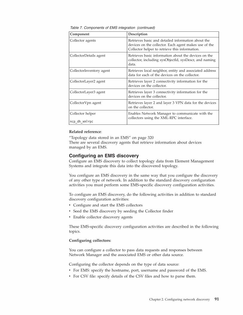
Table 7. Components of EMS integration (continued)
Component Description
Collector agents Retrieves basic and detailed information about thedevices on the collector. Each agent makes use of theCollector helper to retrieve this information.
CollectorDetails agent Retrieves basic information about the devices on thecollector, including sysObjectId, sysDescr, and namingdata.
CollectorInventory agent Retrieves local neighbor, entity and associated addressdata for each of the devices on the collector.
CollectorLayer2 agent Retrieves layer 2 connectivity information for thedevices on the collector.
CollectorLayer3 agent Retrieves layer 3 connectivity information for thedevices on the collector.
CollectorVpn agent Retrieves layer 2 and layer 3 VPN data for the deviceson the collector.
Collector helper
ncp_dh_xmlrpc
Enables Network Manager to communicate with thecollectors using the XML-RPC interface.
Related reference:“Topology data stored in an EMS” on page 320There are several discovery agents that retrieve information about devicesmanaged by an EMS.
Configuring an EMS discoveryConfigure an EMS discovery to collect topology data from Element ManagementSystems and integrate this data into the discovered topology.
You configure an EMS discovery in the same way that you configure the discoveryof any other type of network. In addition to the standard discovery configurationactivities you must perform some EMS-specific discovery configuration activities.
To configure an EMS discovery, do the following activities in addition to standarddiscovery configuration activities:v Configure and start the EMS collectorsv Seed the EMS discovery by seeding the Collector finderv Enable collector discovery agents
These EMS-specific discovery configuration activities are described in the followingtopics.
Configuring collectors:
You can configure a collector to pass data requests and responses betweenNetwork Manager and the associated EMS or other data source.
Configuring the collector depends on the type of data source:v For EMS: specify the hostname, port, username and password of the EMS.v For CSV file: specify details of the CSV files and how to parse them.
Chapter 2. Configuring network discovery 91
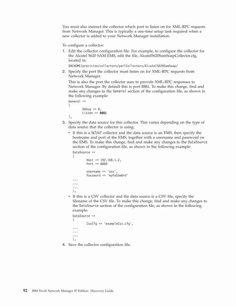
You must also instruct the collector which port to listen on for XML-RPC requestsfrom Network Manager. This is typically a one-time setup task required when anew collector is added to your Network Manager installation.
To configure a collector:1. Edit the collector configuration file. For example, to configure the collector for
the Alcatel 5620 SAM EMS, edit the file, Alcatel5620SamSoapCollector.cfg,located in:$NCHOME/precision/collectors/perlCollectors/Alcatel5620SamSoap/
2. Specify the port the collector must listen on for XML-RPC requests fromNetwork Manager.This is also the port the collector uses to provide XML-RPC responses toNetwork Manager. By default this is port 8081. To make this change, find andmake any changes to the General section of the configuration file, as shown inthe following example:General =>{
Debug => 0,Listen => 8081
},
3. Specify the data source for this collector. This varies depending on the type ofdata source that the collector is using:v If this is a SOAP collector and the data source is an EMS, then specify the
hostname and port of the EMS, together with a username and password onthe EMS. To make this change, find and make any changes to the DataSourcesection of the configuration file, as shown in the following example:DataSource =>{
Host => 192.168.1.2,Port => 8080
Username => ’oss’,Password => ’myPa55w0rd’
...
...
...},
v If this is a CSV collector and the data source is a CSV file, specify thefilename of the CSV file. To make this change, find and make any changes tothe DataSource section of the configuration file, as shown in the followingexample:DataSource =>{
CsvCfg => ’exampleCsv.cfg’,.........},
4. Save the collector configuration file.
92 IBM Tivoli Network Manager IP Edition: Discovery Guide
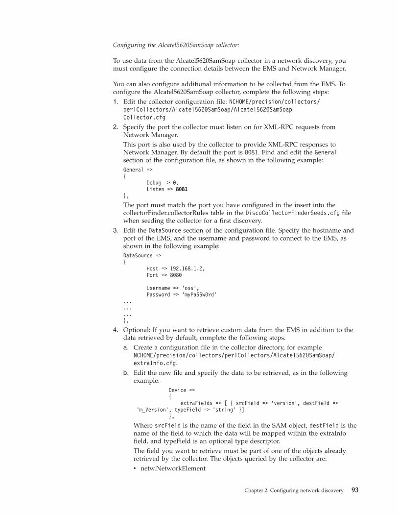
Configuring the Alcatel5620SamSoap collector:
To use data from the Alcatel5620SamSoap collector in a network discovery, youmust configure the connection details between the EMS and Network Manager.
You can also configure additional information to be collected from the EMS. Toconfigure the Alcatel5620SamSoap collector, complete the following steps:1. Edit the collector configuration file: NCHOME/precision/collectors/
perlCollectors/Alcatel5620SamSoap/Alcatel5620SamSoapCollector.cfg
2. Specify the port the collector must listen on for XML-RPC requests fromNetwork Manager.This port is also used by the collector to provide XML-RPC responses toNetwork Manager. By default the port is 8081. Find and edit the Generalsection of the configuration file, as shown in the following example:General =>{
Debug => 0,Listen => 8081
},
The port must match the port you have configured in the insert into thecollectorFinder.collectorRules table in the DiscoCollectorFinderSeeds.cfg filewhen seeding the collector for a first discovery.
3. Edit the DataSource section of the configuration file. Specify the hostname andport of the EMS, and the username and password to connect to the EMS, asshown in the following example:DataSource =>{
Host => 192.168.1.2,Port => 8080
Username => ’oss’,Password => ’myPa55w0rd’
...
...
...},
4. Optional: If you want to retrieve custom data from the EMS in addition to thedata retrieved by default, complete the following steps.a. Create a configuration file in the collector directory, for example
NCHOME/precision/collectors/perlCollectors/Alcatel5620SamSoap/extraInfo.cfg.
b. Edit the new file and specify the data to be retrieved, as in the followingexample:
Device =>{
extraFields => [ { srcField => ’version’, destField =>’m_Version’, typeField => ’string’ }]
},
Where srcField is the name of the field in the SAM object, destField is thename of the field to which the data will be mapped within the extraInfofield, and typeField is an optional type descriptor.The field you want to retrieve must be part of one of the objects alreadyretrieved by the collector. The objects queried by the collector are:v netw.NetworkElement
Chapter 2. Configuring network discovery 93
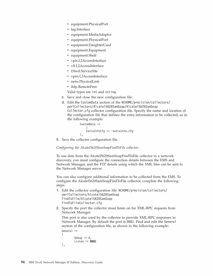
v equipment.PhysicalPortv lag.Interfacev equipment.MediaAdaptorv equipment.PhysicalPortv equipment.DaughterCardv equipment.Equipmentv equipment.Shelfv vpls.L2AccessInterfacev vll.L2AccessInterfacev l3fwd.ServiceSitev vprn.L3AccessInterfacev netw.PhysicalLinkv lldp.RemotePeer.Valid types are int and string.
c. Save and close the new configuration file.d. Edit the CustomData section of the NCHOME/precision/collectors/
perlCollectors/Alcatel5620SamSoap/Alcatel5620SamSoapCollector.cfg collector configuration file. Specify the name and location ofthe configuration file that defines the extra information to be collected, as inthe following example:
CustomData =>{ExtraInfoCfg => ’extraInfo.cfg’
},
5. Save the collector configuration file.
Configuring the Alcatel5620SamSoapFindToFile collector:
To use data from the Alcatel5620SamSoapFindToFile collector in a networkdiscovery, you must configure the connection details between the EMS andNetwork Manager, and the FTP details using which the XML files can be sent tothe Network Manager server.
You can also configure additional information to be collected from the EMS. Toconfigure the Alcatel5620SamSoapFindToFile collector, complete the followingsteps:1. Edit the collector configuration file: NCHOME/precision/collectors/
perlCollectors/Alcatel5620SamSoapFindToFile/Alcatel5620SamSoapFindToFileCollector.cfg
2. Specify the port the collector must listen on for XML-RPC requests fromNetwork Manager.This port is also used by the collector to provide XML-RPC responses toNetwork Manager. By default the port is 8081. Find and edit the Generalsection of the configuration file, as shown in the following example:General =>{
Debug => 0,Listen => 8081
},
94 IBM Tivoli Network Manager IP Edition: Discovery Guide
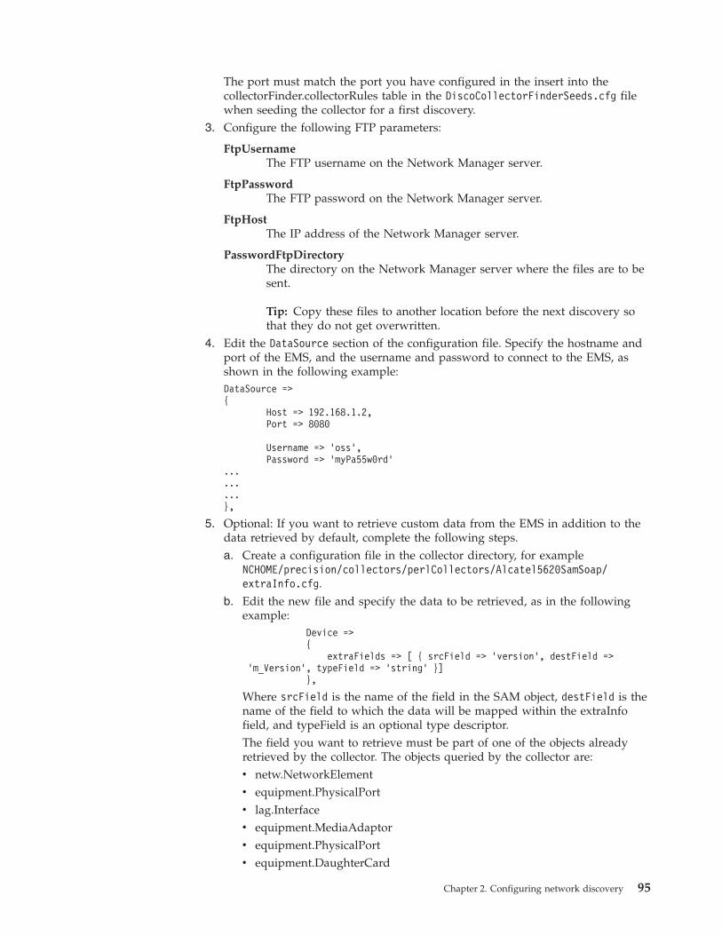
The port must match the port you have configured in the insert into thecollectorFinder.collectorRules table in the DiscoCollectorFinderSeeds.cfg filewhen seeding the collector for a first discovery.
3. Configure the following FTP parameters:
FtpUsernameThe FTP username on the Network Manager server.
FtpPasswordThe FTP password on the Network Manager server.
FtpHostThe IP address of the Network Manager server.
PasswordFtpDirectoryThe directory on the Network Manager server where the files are to besent.
Tip: Copy these files to another location before the next discovery sothat they do not get overwritten.
4. Edit the DataSource section of the configuration file. Specify the hostname andport of the EMS, and the username and password to connect to the EMS, asshown in the following example:DataSource =>{
Host => 192.168.1.2,Port => 8080
Username => ’oss’,Password => ’myPa55w0rd’
...
...
...},
5. Optional: If you want to retrieve custom data from the EMS in addition to thedata retrieved by default, complete the following steps.a. Create a configuration file in the collector directory, for example
NCHOME/precision/collectors/perlCollectors/Alcatel5620SamSoap/extraInfo.cfg.
b. Edit the new file and specify the data to be retrieved, as in the followingexample:
Device =>{
extraFields => [ { srcField => ’version’, destField =>’m_Version’, typeField => ’string’ }]
},
Where srcField is the name of the field in the SAM object, destField is thename of the field to which the data will be mapped within the extraInfofield, and typeField is an optional type descriptor.The field you want to retrieve must be part of one of the objects alreadyretrieved by the collector. The objects queried by the collector are:v netw.NetworkElementv equipment.PhysicalPortv lag.Interfacev equipment.MediaAdaptorv equipment.PhysicalPortv equipment.DaughterCard
Chapter 2. Configuring network discovery 95
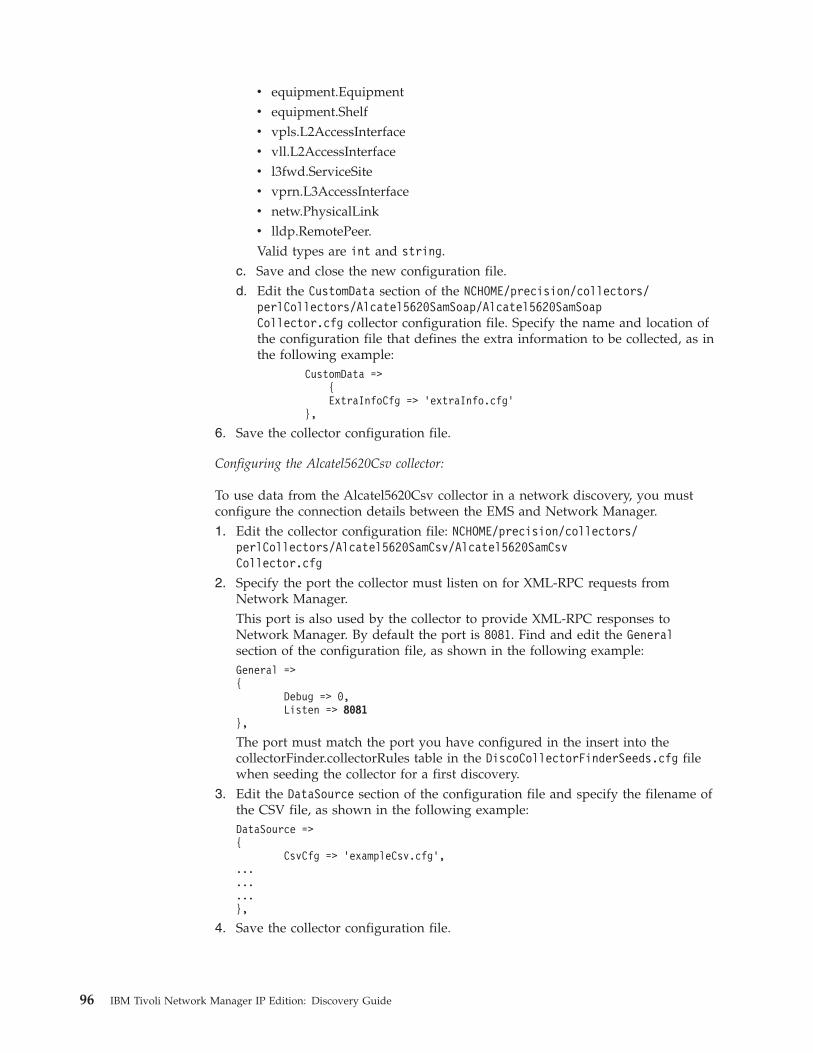
v equipment.Equipmentv equipment.Shelfv vpls.L2AccessInterfacev vll.L2AccessInterfacev l3fwd.ServiceSitev vprn.L3AccessInterfacev netw.PhysicalLinkv lldp.RemotePeer.Valid types are int and string.
c. Save and close the new configuration file.d. Edit the CustomData section of the NCHOME/precision/collectors/
perlCollectors/Alcatel5620SamSoap/Alcatel5620SamSoapCollector.cfg collector configuration file. Specify the name and location ofthe configuration file that defines the extra information to be collected, as inthe following example:
CustomData =>{ExtraInfoCfg => ’extraInfo.cfg’
},
6. Save the collector configuration file.
Configuring the Alcatel5620Csv collector:
To use data from the Alcatel5620Csv collector in a network discovery, you mustconfigure the connection details between the EMS and Network Manager.1. Edit the collector configuration file: NCHOME/precision/collectors/
perlCollectors/Alcatel5620SamCsv/Alcatel5620SamCsvCollector.cfg
2. Specify the port the collector must listen on for XML-RPC requests fromNetwork Manager.This port is also used by the collector to provide XML-RPC responses toNetwork Manager. By default the port is 8081. Find and edit the Generalsection of the configuration file, as shown in the following example:General =>{
Debug => 0,Listen => 8081
},
The port must match the port you have configured in the insert into thecollectorFinder.collectorRules table in the DiscoCollectorFinderSeeds.cfg filewhen seeding the collector for a first discovery.
3. Edit the DataSource section of the configuration file and specify the filename ofthe CSV file, as shown in the following example:DataSource =>{
CsvCfg => ’exampleCsv.cfg’,.........},
4. Save the collector configuration file.
96 IBM Tivoli Network Manager IP Edition: Discovery Guide
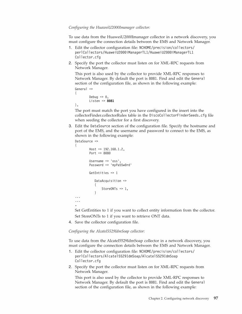
Configuring the HuaweiU2000Imanager collector:
To use data from the HuaweiU2000Imanager collector in a network discovery, youmust configure the connection details between the EMS and Network Manager.1. Edit the collector configuration file: NCHOME/precision/collectors/
perlCollectors/HuaweiU2000iManagerTL1/HuaweiU2000iManagerTL1Collector.cfg
2. Specify the port the collector must listen on for XML-RPC requests fromNetwork Manager.This port is also used by the collector to provide XML-RPC responses toNetwork Manager. By default the port is 8081. Find and edit the Generalsection of the configuration file, as shown in the following example:General =>{
Debug => 0,Listen => 8081
},
The port must match the port you have configured in the insert into thecollectorFinder.collectorRules table in the DiscoCollectorFinderSeeds.cfg filewhen seeding the collector for a first discovery.
3. Edit the DataSource section of the configuration file. Specify the hostname andport of the EMS, and the username and password to connect to the EMS, asshown in the following example:DataSource =>{
Host => 192.168.1.2,Port => 8080
Username => ’oss’,Password => ’myPa55w0rd’
GetEntities => 1
DataAcquisition =>{
StoreONTs => 1,}
...
...,
Set GetEntities to 1 if you want to collect entity information from the collector.Set StoreONTs to 1 if you want to retrieve ONT data.
4. Save the collector configuration file.
Configuring the Alcatel5529IdmSoap collector:
To use data from the Alcatel5529IdmSoap collector in a network discovery, youmust configure the connection details between the EMS and Network Manager.1. Edit the collector configuration file: NCHOME/precision/collectors/
perlCollectors/Alcatel5529IdmSoap/Alcatel5529IdmSoapCollector.cfg
2. Specify the port the collector must listen on for XML-RPC requests fromNetwork Manager.This port is also used by the collector to provide XML-RPC responses toNetwork Manager. By default the port is 8081. Find and edit the Generalsection of the configuration file, as shown in the following example:
Chapter 2. Configuring network discovery 97
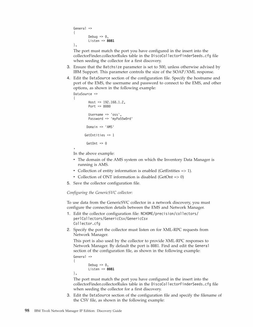
General =>{
Debug => 0,Listen => 8081
},
The port must match the port you have configured in the insert into thecollectorFinder.collectorRules table in the DiscoCollectorFinderSeeds.cfg filewhen seeding the collector for a first discovery.
3. Ensure that the Batchsize parameter is set to 500, unless otherwise advised byIBM Support. This parameter controls the size of the SOAP/XML response.
4. Edit the DataSource section of the configuration file. Specify the hostname andport of the EMS, the username and password to connect to the EMS, and otheroptions, as shown in the following example:DataSource =>{
Host => 192.168.1.2,Port => 8080
Username => ’oss’,Password => ’myPa55w0rd’
Domain => ’AMS’
GetEntities => 1
GetOnt => 0,
In the above example:v The domain of the AMS system on which the Inventory Data Manager is
running is AMS.v Collection of entity information is enabled (GetEntities => 1).v Collection of ONT information is disabled (GetOnt => 0)
5. Save the collector configuration file.
Configuring the GenericSVC collector:
To use data from the GenericSVC collector in a network discovery, you mustconfigure the connection details between the EMS and Network Manager.1. Edit the collector configuration file: NCHOME/precision/collectors/
perlCollectors/GenericCsv/GenericCsvCollector.cfg
2. Specify the port the collector must listen on for XML-RPC requests fromNetwork Manager.This port is also used by the collector to provide XML-RPC responses toNetwork Manager. By default the port is 8081. Find and edit the Generalsection of the configuration file, as shown in the following example:General =>{
Debug => 0,Listen => 8081
},
The port must match the port you have configured in the insert into thecollectorFinder.collectorRules table in the DiscoCollectorFinderSeeds.cfg filewhen seeding the collector for a first discovery.
3. Edit the DataSource section of the configuration file and specify the filename ofthe CSV file, as shown in the following example:
98 IBM Tivoli Network Manager IP Edition: Discovery Guide
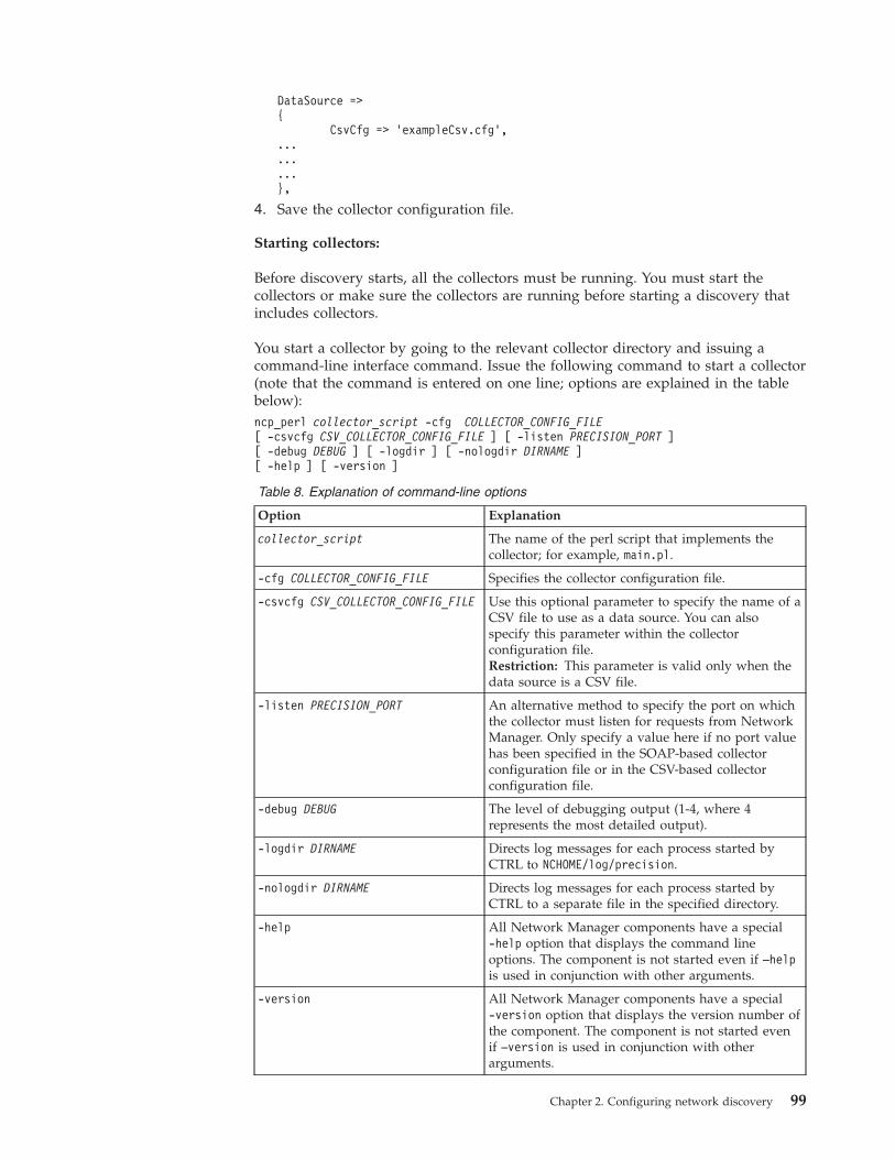
DataSource =>{
CsvCfg => ’exampleCsv.cfg’,.........},
4. Save the collector configuration file.
Starting collectors:
Before discovery starts, all the collectors must be running. You must start thecollectors or make sure the collectors are running before starting a discovery thatincludes collectors.
You start a collector by going to the relevant collector directory and issuing acommand-line interface command. Issue the following command to start a collector(note that the command is entered on one line; options are explained in the tablebelow):ncp_perl collector_script -cfg COLLECTOR_CONFIG_FILE[ -csvcfg CSV_COLLECTOR_CONFIG_FILE ] [ -listen PRECISION_PORT ][ -debug DEBUG ] [ -logdir ] [ -nologdir DIRNAME ][ -help ] [ -version ]
Table 8. Explanation of command-line options
Option Explanation
collector_script The name of the perl script that implements thecollector; for example, main.pl.
-cfg COLLECTOR_CONFIG_FILE Specifies the collector configuration file.
-csvcfg CSV_COLLECTOR_CONFIG_FILE Use this optional parameter to specify the name of aCSV file to use as a data source. You can alsospecify this parameter within the collectorconfiguration file.Restriction: This parameter is valid only when thedata source is a CSV file.
-listen PRECISION_PORT An alternative method to specify the port on whichthe collector must listen for requests from NetworkManager. Only specify a value here if no port valuehas been specified in the SOAP-based collectorconfiguration file or in the CSV-based collectorconfiguration file.
-debug DEBUG The level of debugging output (1-4, where 4represents the most detailed output).
-logdir DIRNAME Directs log messages for each process started byCTRL to NCHOME/log/precision.
-nologdir DIRNAME Directs log messages for each process started byCTRL to a separate file in the specified directory.
-help All Network Manager components have a special-help option that displays the command lineoptions. The component is not started even if –helpis used in conjunction with other arguments.
-version All Network Manager components have a special-version option that displays the version number ofthe component. The component is not started evenif –version is used in conjunction with otherarguments.
Chapter 2. Configuring network discovery 99
Seeding an EMS discovery:
Seed the EMS discovery by seeding the Collector finder. This is typically aone-time setup task required when a new collector is added to your installation.
To enable Network Manager to find the collectors, you must seed the Collectorfinder. Seeding the Collector finder involves specifying for each collector:v The hostname of the device on which the collector is runningv The port on that device on which the collector is listening
If a collector is running on the same host as Network Manager, then you need onlyspecify the port.
Note: If you are rediscovering a device using the Collector finder, then specify theIP address of the device or subnet to rediscover using the Discovery ConfigurationGUI.
You can seed the Collector finder to perform a discovery or to perform a partialrediscovery of a single device or subnet. If you seed the Collector finder toperform a partial rediscovery, then you can also specify a single device or subnetretrieved by the collector.
You must seed the Collector finder with the host name of the device on which thecollector is running, and the port on that device on which the collector is listening.If the collector is running on the same host as Network Manager, then you need tospecify only the port.
Seeding the Collector for a first discovery
You seed the Collector finder for a first discovery by appending an insert into thecollectorFinder.collectorRules table to the DiscoCollectorFinderSeeds.cfgconfiguration file. The following insert seeds the Collector finder with a host nameof 172.16.25.1, and a port of 8082. This insert means that the collector is running ona host with IP address 172.16.25.0, which is different to the host on which NetworkManager is running. The override number of retries for this collector is 5.insert into collectorFinder.collectorRules(
m_Host,m_Port,m_NumRetries
)values(
"172.16.25.1",8082,5
);
100 IBM Tivoli Network Manager IP Edition: Discovery Guide
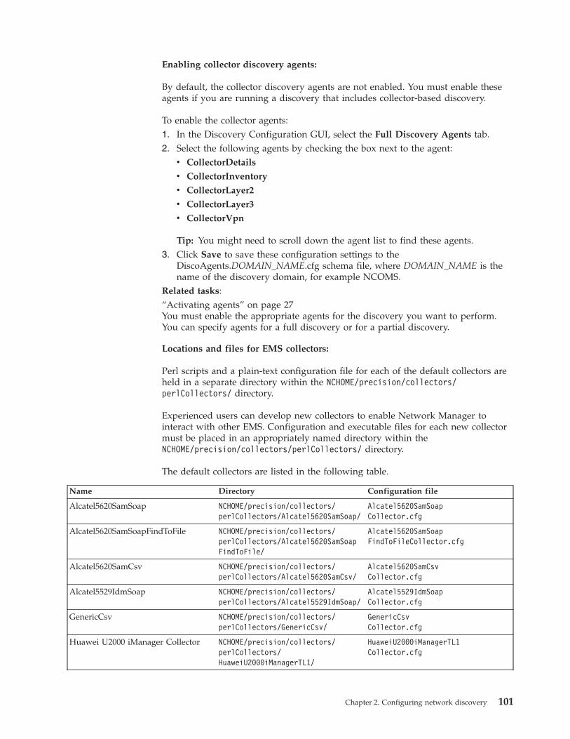
Enabling collector discovery agents:
By default, the collector discovery agents are not enabled. You must enable theseagents if you are running a discovery that includes collector-based discovery.
To enable the collector agents:1. In the Discovery Configuration GUI, select the Full Discovery Agents tab.2. Select the following agents by checking the box next to the agent:
v CollectorDetails
v CollectorInventory
v CollectorLayer2
v CollectorLayer3
v CollectorVpn
Tip: You might need to scroll down the agent list to find these agents.3. Click Save to save these configuration settings to the
DiscoAgents.DOMAIN_NAME.cfg schema file, where DOMAIN_NAME is thename of the discovery domain, for example NCOMS.
Related tasks:“Activating agents” on page 27You must enable the appropriate agents for the discovery you want to perform.You can specify agents for a full discovery or for a partial discovery.
Locations and files for EMS collectors:
Perl scripts and a plain-text configuration file for each of the default collectors areheld in a separate directory within the NCHOME/precision/collectors/perlCollectors/ directory.
Experienced users can develop new collectors to enable Network Manager tointeract with other EMS. Configuration and executable files for each new collectormust be placed in an appropriately named directory within theNCHOME/precision/collectors/perlCollectors/ directory.
The default collectors are listed in the following table.
Name Directory Configuration file
Alcatel5620SamSoap NCHOME/precision/collectors/perlCollectors/Alcatel5620SamSoap/
Alcatel5620SamSoapCollector.cfg
Alcatel5620SamSoapFindToFile NCHOME/precision/collectors/perlCollectors/Alcatel5620SamSoapFindToFile/
Alcatel5620SamSoapFindToFileCollector.cfg
Alcatel5620SamCsv NCHOME/precision/collectors/perlCollectors/Alcatel5620SamCsv/
Alcatel5620SamCsvCollector.cfg
Alcatel5529IdmSoap NCHOME/precision/collectors/perlCollectors/Alcatel5529IdmSoap/
Alcatel5529IdmSoapCollector.cfg
GenericCsv NCHOME/precision/collectors/perlCollectors/GenericCsv/
GenericCsvCollector.cfg
Huawei U2000 iManager Collector NCHOME/precision/collectors/perlCollectors/HuaweiU2000iManagerTL1/
HuaweiU2000iManagerTL1Collector.cfg
Chapter 2. Configuring network discovery 101
Configuring a context-sensitive discoveryIf you have devices that you need to discover such as SMS devices, MPLS Edgedevices, or other devices with virtual routers, you must run a context-sensitivediscovery. Context-sensitive discovery ensures correct representation of virtualrouters. Always check that your particular device type is supported for discovery.
In a context-sensitive discovery, information about a device is passed from thereturns table of the Details agent to the despatch table of the relevant Contextagent.
The Context agents use the filters in the files with an extension of .agent todetermine which devices to process. This is true for all discovery agents. If thedevice is not of a type which supports virtual routers, that is, does not needcontext-sensitive processing, it is passed directly to the Associated Address agent.
Attention: Enabling a context-sensitive discovery automatically enables all theContext agents. Disabling a context-sensitive discovery automatically disables allthe Context agents. Do not manually enable or disable Context agents, eitherthrough the configuration files or through the Discovery Configuration GUI.
To enable a context-sensitive discovery, append the following insert to theDiscoConfig.cfg file:insert into disco.config(
m_UseContext)values(
1)
Inserting the value 0 disables the context-sensitive discovery.Related concepts:“Discovering device details (context-sensitive)” on page 288The discovery of context-sensitive device details is carried out in several steps.Related reference:“Context-sensitive discovery agents” on page 329There are several agents that take part in a context-sensitive discovery.
Configuring MPLS discoveriesConfigure an MPLS discovery to discover core MPLS networks and the VPNs thatuse these core networks. Advanced MPLS discovery configuration provides extracustomization facilities.
102 IBM Tivoli Network Manager IP Edition: Discovery Guide
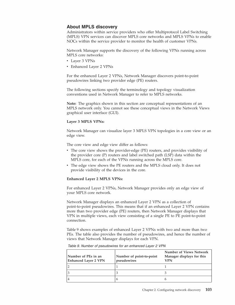
About MPLS discoveryAdministrators within service providers who offer Multiprotocol Label Switching(MPLS) VPN services can discover MPLS core networks and MPLS VPNs to enableNOCs within the service provider to monitor the health of customer VPNs.
Network Manager supports the discovery of the following VPNs running acrossMPLS core networks:v Layer 3 VPNsv Enhanced Layer 2 VPNs
For the enhanced Layer 2 VPNs, Network Manager discovers point-to-pointpseudowires linking two provider edge (PE) routers.
The following sections specify the terminology and topology visualizationconventions used in Network Manager to refer to MPLS networks.
Note: The graphics shown in this section are conceptual representations of anMPLS network only. You cannot see these conceptual views in the Network Viewsgraphical user interface (GUI).
Layer 3 MPLS VPNs:
Network Manager can visualize layer 3 MPLS VPN topologies in a core view or anedge view.
The core view and edge view differ as follows:v The core view shows the provider-edge (PE) routers, and provides visibility of
the provider core (P) routers and label switched path (LSP) data within theMPLS core, for each of the VPNs running across the MPLS core.
v The edge view shows the PE routers and the MPLS cloud only. It does notprovide visibility of the devices in the core.
Enhanced Layer 2 MPLS VPNs:
For enhanced Layer 2 VPNs, Network Manager provides only an edge view ofyour MPLS core network.
Network Manager displays an enhanced Layer 2 VPN as a collection ofpoint-to-point pseudowires. This means that if an enhanced Layer 2 VPN containsmore than two provider edge (PE) routers, then Network Manager displays thatVPN in multiple views, each view consisting of a single PE to PE point-to-pointconnection.
Table 9 shows examples of enhanced Layer 2 VPNs with two and more than twoPEs. The table also provides the number of pseudowires, and hence the number ofviews that Network Manager displays for each VPN.
Table 9. Number of pseudowires for an enhanced Layer 2 VPN
Number of PEs in anEnhanced Layer 2 VPN
Number of point-to-pointpseudowires
Number of Views NetworkManager displays for thisVPN
2 1 1
3 3 3
4 6 6
Chapter 2. Configuring network discovery 103

Standard and advanced MPLS discovery configuration:
Configure a standard MPLS discovery to discover all of your MPLS network anduses default naming convention for the VPNs discovered. The standard MPLSdiscovery configuration also enables the display of service-affected events (SAEs)in the Active Event List (AEL). Advanced MPLS discovery configuration providesextra customization facilities.
Configuration activities for an MPLS network include seeding, scoping, and theother standard discovery activities.
Standard and advanced MPLS discovery configuration differ as follows:v Standard MPLS discovery: discovers all of your MPLS network and uses default
naming convention for the VPNs discoveredv Advanced MPLS discovery: using the advanced configuration options you can:
– Restrict the scope of the discovery to a particular VPN or VRF– Configure your own VPN naming conventions– Force label discovery even if you selected an RT-based discovery
After you have configured and run an MPLS discovery, your operators canmonitor customer VPNs in the following ways:v View topology maps of selected VPNs, showing the alert status of the VPNs and
of the devices in the VPNs .v Identify service-affected events (SAEs) in the Active Event List (AEL). An SAE is
an alert that warns operators that a critical customer service, for example, acustomer VPN, has been affected by one or more network events. Theunderlying network events are on an interface on either a PE router or a CErouter.
About Service Affected Events:
A Service Affected Event (SAE) alert warns operators that a critical customerservice has been affected by one or more network events.
An SAE is produced when one or more events occur on a Provider Edge (PE) orCustomer Edge (CE) interface in a Virtual Private Network (VPN) or VirtualPrivate LAN Service (VPLS). The underlying network events are on an interface ofa PE router or a CE router, or on the link between them. You must configure theMPLS discovery to infer the existence of CE routers so all possible SAEs aregenerated for your customer VPNs.
The following list gives two examples of SAE events generated on two differentcustomer VPNs:v SAE generated on customer-1 VPN because of an Mpls VRF Down trap on a PE
router interfacev SAE generated on customer-3 VPN because of a LinkDown trap on a CE router
interface
Each SAE appears as an alert in the Active Event List (AEL). The appearance of theSAE warns operators that a customer VPN has been affected, possibly critically, byone or more network events. Operators can right-click the SAE and issue acommand to view the underlying events that caused the SAE.
104 IBM Tivoli Network Manager IP Edition: Discovery Guide
For more information about the AEL, see the IBM Tivoli Netcool/OMNIbus Web GUIAdministration and User's Guide.
Configuring standard MPLS discoveryConfigure an MPLS discovery to discover core MPLS networks and the VPNs thatuse these core networks.
In addition to the standard discovery configuration activities, you must performsome MPLS-specific discovery configuration activities:v Configure MPLS agentsv Specify the discovery methods, that is, whether to run a route-target or
label-switched path (LSP) discoveryv Configure SNP and Telnet to ensure that the agents can access network devicesv Configure Network Manager to infer the existence of CE routers. This step is
necessary to enable operators to view service-affected events in the Active EventList (AEL).
These EMS-specific discovery configuration activities are described in the followingtopics.
Configuring MPLS agents:
As part of MPLS discovery configuration you must enable one or more MPLSagents. You can also resolve the problem of duplicate IP addresses in differentVirtual Private Networks (VPNs) by configuring the AsAgent agent.
The following MPLS agents and the corresponding agent definition (.agnt) files areprovided:v Juniper Telnet agent (JuniperMPLSTelnet.agnt)v Juniper ERX router agent (UnisphereMPLSTelnet.agnt)v Cisco MPLS Telnet agent (CiscoMPLSTelnet.agnt)v Cisco MPLS SNMP agent (CiscoMPLSSnmp.agnt)v Laurel MPLS Telnet agent (LaurelMPLSTelnet.agnt)
Note: The Laurel MPLS Telnet agent is intended for RT- (RouteTarget) baseddiscoveries only.
These agents can discover MPLS VPN and Virtual Private LAN Service (VPLS)data from devices in the network.
Tip: Agents that retrieve VPLS information can retrieve large amounts of data.Enabling these agents can add significant processing time to the discovery process.If you do not need to rediscover VPLS information, disable these agents for a fasterdiscovery.
Note: If you have an MPLS network that supports both Layer 3 and enhancedLayer 2 VPNs, then the same MPLS agents discover both types of VPN. NetworkViews can also partition both Layer 3 and enhanced Layer 2 VPNs simultaneouslyon the same core MPLS network.
If your MPLS network contains Cisco equipment, enable both the Cisco MPLSTelnet and Cisco MPLS SNMP agents. These two agents complement each other, asfollows:
Chapter 2. Configuring network discovery 105
v Cisco MPLS SNMP agent targets only devices with an Internetwork OperatingSystem (IOS) that fully supports SNMP-based MPLS discovery
v CiscoMPLSTelnet agent targets only devices running an IOS that does not fullysupport an SNMP-based discovery
Attention: Use caution when altering the CiscMPLSSnmp.agnt file. Some networkdevices might contain IOS versions that have a flaw that might affect the devicewhen certain MPLS SNMP data is requested. These IOS versions have been filteredout by default in the CiscMPLSSnmp.agnt file.
In addition to these standard discovery configuration activities, you can alsochange the scope of the MPLS discovery by restricting the scope to specific VPNsor VRFs.Related tasks:“Defining the scope of an MPLS/VPN discovery” on page 113When configuring the discovery of one or more Virtual Private Networks ( VPNs )running across an MPLS core, you can restrict the scope of this discovery to aparticular VPN name or VPN Routing and Forwarding (VRF) table name.
Configuring MPLS Telnet agents:
The CiscoMPLSTelnet, JuniperMPLSTelnet, LaurelMPLSTelnet, andUnisphereMPLSTelnet agents obtain data from devices primarily through Telnet.You must enable these agents and configure Telnet access to ensure that MPLSTelnet agents can access devices and can understand the output from devices.
Do the following to configure Telnet access for MPLS Telnet agents:1. Populate the Telnet configuration file TelnetStackPasswords.cfg so the agents
can access the target devices.2. Configure the Telnet Helper so that agents can understand the output from
devices.Related tasks:“Configuring device access” on page 23Specify SNMP community strings and Telnet access information to enable helpersand Network Manager polling to access devices on your network.Related reference:“TelnetStackPasswords.cfg configuration file” on page 78The TelnetStackPasswords.cfg configuration file defines access credentials for Telnetaccess to devices.
Configuring MPLS SNMP agents:
The CiscoMPLSSnmp agent obtains data from devices using SNMP. You mustenable this agent and configure SNMP access to ensure that this agent can accessdevices and can understand the output from devices.
To configure SNMP access for MPLS SNMP agents:
Note: The CiscoMPLSSnmp.agnt attempts to retrieve the L2 VPNs using the telnet'show' commands if the agent fails to retrieve the data via SNMP.1. Configure SNMP access to devices.2. Configure the SNMP Helper so that agents can understand the output from
devices.
106 IBM Tivoli Network Manager IP Edition: Discovery Guide
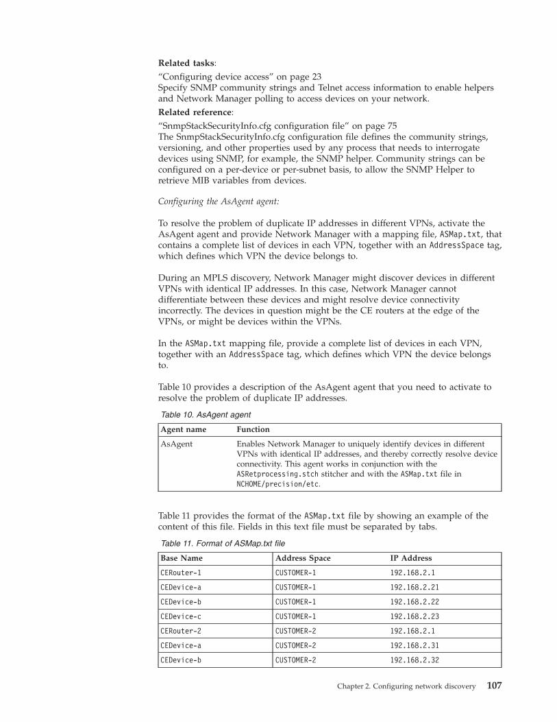
Related tasks:“Configuring device access” on page 23Specify SNMP community strings and Telnet access information to enable helpersand Network Manager polling to access devices on your network.Related reference:“SnmpStackSecurityInfo.cfg configuration file” on page 75The SnmpStackSecurityInfo.cfg configuration file defines the community strings,versioning, and other properties used by any process that needs to interrogatedevices using SNMP, for example, the SNMP helper. Community strings can beconfigured on a per-device or per-subnet basis, to allow the SNMP Helper toretrieve MIB variables from devices.
Configuring the AsAgent agent:
To resolve the problem of duplicate IP addresses in different VPNs, activate theAsAgent agent and provide Network Manager with a mapping file, ASMap.txt, thatcontains a complete list of devices in each VPN, together with an AddressSpace tag,which defines which VPN the device belongs to.
During an MPLS discovery, Network Manager might discover devices in differentVPNs with identical IP addresses. In this case, Network Manager cannotdifferentiate between these devices and might resolve device connectivityincorrectly. The devices in question might be the CE routers at the edge of theVPNs, or might be devices within the VPNs.
In the ASMap.txt mapping file, provide a complete list of devices in each VPN,together with an AddressSpace tag, which defines which VPN the device belongsto.
Table 10 provides a description of the AsAgent agent that you need to activate toresolve the problem of duplicate IP addresses.
Table 10. AsAgent agent
Agent name Function
AsAgent Enables Network Manager to uniquely identify devices in differentVPNs with identical IP addresses, and thereby correctly resolve deviceconnectivity. This agent works in conjunction with theASRetprocessing.stch stitcher and with the ASMap.txt file inNCHOME/precision/etc.
Table 11 provides the format of the ASMap.txt file by showing an example of thecontent of this file. Fields in this text file must be separated by tabs.
Table 11. Format of ASMap.txt file
Base Name Address Space IP Address
CERouter-1 CUSTOMER-1 192.168.2.1
CEDevice-a CUSTOMER-1 192.168.2.21
CEDevice-b CUSTOMER-1 192.168.2.22
CEDevice-c CUSTOMER-1 192.168.2.23
CERouter-2 CUSTOMER-2 192.168.2.1
CEDevice-a CUSTOMER-2 192.168.2.31
CEDevice-b CUSTOMER-2 192.168.2.32
Chapter 2. Configuring network discovery 107
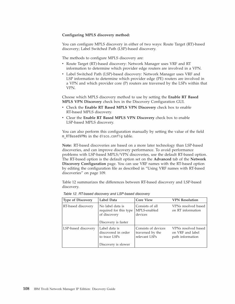
Configuring MPLS discovery method:
You can configure MPLS discovery in either of two ways: Route Target (RT)-baseddiscovery; Label Switched Path (LSP)-based discovery.
The methods to configure MPLS discovery are:v Route Target (RT)-based discovery: Network Manager uses VRF and RT
information to determine which provider edge routers are involved in a VPN.v Label Switched Path (LSP)-based discovery: Network Manager uses VRF and
LSP information to determine which provider edge (PE) routers are involved ina VPN and which provider core (P) routers are traversed by the LSPs within thatVPN.
Choose which MPLS discovery method to use by setting the Enable RT BasedMPLS VPN Discovery check box in the Discovery Configuration GUI.v Check the Enable RT Based MPLS VPN Discovery check box to enable
RT-based MPLS discovery.v Clear the Enable RT Based MPLS VPN Discovery check box to enable
LSP-based MPLS discovery.
You can also perform this configuration manually by setting the value of the fieldm_RTBasedVPNs in the disco.config table.
Note: RT-based discoveries are based on a more later technology than LSP-baseddiscoveries, and can improve discovery performance. To avoid performanceproblems with LSP-based MPLS/VPN discoveries, use the default RT-based option.The RT-based option is the default option set on the Advanced tab of the NetworkDiscovery Configuration page. You can use VRF names with the RT-based optionby editing the configuration file as described in “Using VRF names with RT-baseddiscoveries” on page 109.
Table 12 summarizes the differences between RT-based discovery and LSP-baseddiscovery.
Table 12. RT-based discovery and LSP-based discovery
Type of Discovery Label Data Core View VPN Resolution
RT-based discovery No label data isrequired for this typeof discovery
Discovery is faster
Consists of allMPLS-enableddevices
VPNs resolved basedon RT information
LSP-based discovery Label data isdiscovered in orderto trace LSPs
Discovery is slower
Consists of devicestraversed by therelevant LSPs
VPNs resolved basedon VRF and labelpath information
108 IBM Tivoli Network Manager IP Edition: Discovery Guide
Related reference:“Advanced discovery parameters” on page 37Advanced settings control features of the discovery such as concurrent processesand timeouts. Use these parameters to increase the speed of the discovery, butbalance the speed with the load on the server. Generally, a faster discovery resultsin more memory usage on the server.“disco.config table” on page 183The config table configures the general operation of the discovery process.
Using VRF names with RT-based discoveries:
You might prefer the LSP-based discoveries in order to use the more familiar VRFname for the VPNs. However, you can also use VRF names with the RT-baseddiscoveries.
To use VRF names with RT-based discoveries:1. Exit all instances of the Discovery Configuration GUI.2. Go to the NCHOME/etc/precision directory.3. Edit the DiscoConfig.DomainName.cfg file as follows:
a. Set the m_RTVPNResolution field to 2 in the disco.config table.b. Ensure that the m_RTBasedVPNs value is set to 1.
4. Restart the ncp processes to read the configuration files again:itnm_stop ncpitnm_start ncp
Alternatively, restart the ncp_config process.
Inferring the existence of CE routers:
You can infer the existence of your customers’ CE routers by making specificationsin the advanced discovery configuration options within the DiscoveryConfiguration GUI.
If the host on which Network Manager is installed has no access to yourcustomers’ CE routers, then Network Manager cannot discover these routersdirectly. This situation typically occurs when the company providing MPLSservices owns the PE routers but has no access to CE routers, which are owned bythe customers running the VPNs.
Note: This situation does not occur if the company providing MPLS services ownsand manages both PE and CE routers and therefore has access to both sets ofdevices.
To infer the existence of your customers’ CE routers, specify this in the advanceddiscovery configuration options within the Discovery Configuration GUI.
Note: You should do this only where the PE interface is on a /30 subnet. In thiscase, the other device on the subnet must be the CE router, and the IP address ofthe CE will be the other address on the /30 subnet.
Limitations on inferring CE routers:
v Avoid inferring the existence of CE routers if your PE routers are connected tothe CE routers by serial links and you know that there is IP address duplicationamong the CE routers and devices within the MPLS core network. Network
Chapter 2. Configuring network discovery 109
Manager will remove from the topology any discovered MPLS core routers thathave the same IP address as an inferred CE IP address.
v If your PE routers are connected to the CE routers by Ethernet, you can infer theexistence of CE routers without needing to perform any other checks. In thiscase, Network Manager can determine the MAC address of the CE router. IfNetwork Manager has discovered another device with the same MAC address,then it must be the CE router. In this case, Network Manager uses thediscovered device data and does not infer the existence of the CE.
Related reference:“Advanced discovery parameters” on page 37Advanced settings control features of the discovery such as concurrent processesand timeouts. Use these parameters to increase the speed of the discovery, butbalance the speed with the load on the server. Generally, a faster discovery resultsin more memory usage on the server.
Configuring advanced MPLS discoveryConfigure an advanced MPLS discovery for extra customization facilities notincluded in the standard MPLS discovery.
When you configure an advanced MPLS discovery, you must perform thefollowing activities in addition to the activities required for a standard MPLSdiscovery.v Define the scope of the MPLS discovery: enables you to restrict the scope of this
discovery to a particular VPN or VRF.v Specify a VPN name: enables you to configure your own VPN naming
conventionv Fine-tune label data discovery: enables you to force LSP discovery regardless of
the MPLS discovery method selected
Configuring discovery of MPLS Traffic Engineered tunnels:
To discover MPLS Traffic Engineered tunnels, enable the StandardMPLSTE agent,configure the information that is retrieved, and configure the scope of thediscovery.
MPLS Traffic Engineered tunnel discovery modes:
Set the discovery mode according to how much detail you want to retrieve.
A mode-switch is provided in the discovery agent configuration file that configuresspecific tunnel instances, which can be wildcarded, to retrieve different amounts oftunnel data. You can choose any of the following modes.
HeadEndHops (default)
In HeadEndHops mode, the agent retrieves head-end and tail-end of thetunnel, and the transit LSRs and next-hop interfaces are identified byquerying the head-end LSR for computed and actual-route hop data. Theactual and computed route data is retrieved from themplsTunnelARHopTable and mplsTunnelCHopTable MIB tablesrespectively. This discovery mode does not store transit and tail-end tunnelinstances against transit and tail-end LSRs. A connection is created in theMPLS TE topology between the head-end and tail-end LSR interfaces viatransit device hops (if present) which are associated with the head-end LSRtunnel object for the appropriate tunnel interface.
110 IBM Tivoli Network Manager IP Edition: Discovery Guide
MPLS cross-connect pointers that are discovered and resolved on the headtunnel will be resolved to the appropriate LSP ID where possible.
You can use this information to determine if the actual path taken by atunnel is different to the path computed by the Compute Shortest PathFirst (CSPF) calculations. You can see the computed and actual path,although there is no way to determine that an LSR is acting in a transit ortail capacity without looking at the head-end LSR tunnel data.
Note: Actual route data is only available if the Record Route Option (RRO)has been specified for the tunnel instance.
In the schema of the scope.mplsTe table, the HeadEndHops mode maps tovalue 1 of m_Mode.
HeadTailEnd
In HeadTailEnd mode, only MPLS TE tunnel head-end and tail-end pointsare resolved, by querying the head-end Label Switching Router (LSR). Thismode provides the minimal amount of information about the MPLS TEtunnels. A connection in the MPLS TE topology is created between thehead-end and tail-end LSR interfaces. A tunnel resource instance isassociated with the head-end tunnel LSR entity.
In this mode, you cannot identify the transit LSRs, and computed andactual route data is not retrieved.
MPLS cross-connect pointers that are discovered and resolved on the headtunnel will be resolved to the appropriate LSP ID where possible.
In the schema of the scope.mplsTe table, the HeadTailEnd mode maps tovalue 2 of m_Mode.
AllLSRTunnelsAndHops
In AllLSRTunnelsAndHops mode, the agent retrieves the head-end andtail-end of the tunnel and identifies transit LSRs and next-hop interfaces byquerying the head-end LSR for computed and actual route hop data. Theactual and computed route data is retrieved from themplsTunnelARHopTable and mplsTunnelCHopTable MIB tablesrespectively. This discovery mode stores transit and tail-end tunnelinstances against transit and tail-end LSRs. The mode creates a connectionin the MPLS TE topology between the head-end and tail-end LSRinterfaces that are associated with the head-end (for the tunnel interface)and transit and tail-end LSR tunnel objects. Computed and actual-routeconnections are associated with Computed and Actual connection entitytypes, which are aggregated in sequence from the head-end LSR tunnelentity. A tunnel resource instance is associated with the head-end tunnelLSR entity.
You can use this information to determine if the actual path taken by atunnel is different to the path computed by the CSPF calculations. You cansee the computed and actual path and determine the transit or tail-end roleof an LSR without looking at the headend LSR tunnel instance.
Note: Actual route data is only available if the Record Route Option (RRO)has been specified for the tunnel instance.
MPLS cross-connect pointers that are discovered and resolved on the headtunnel will be resolved to the appropriate LSP ID where possible.
Chapter 2. Configuring network discovery 111
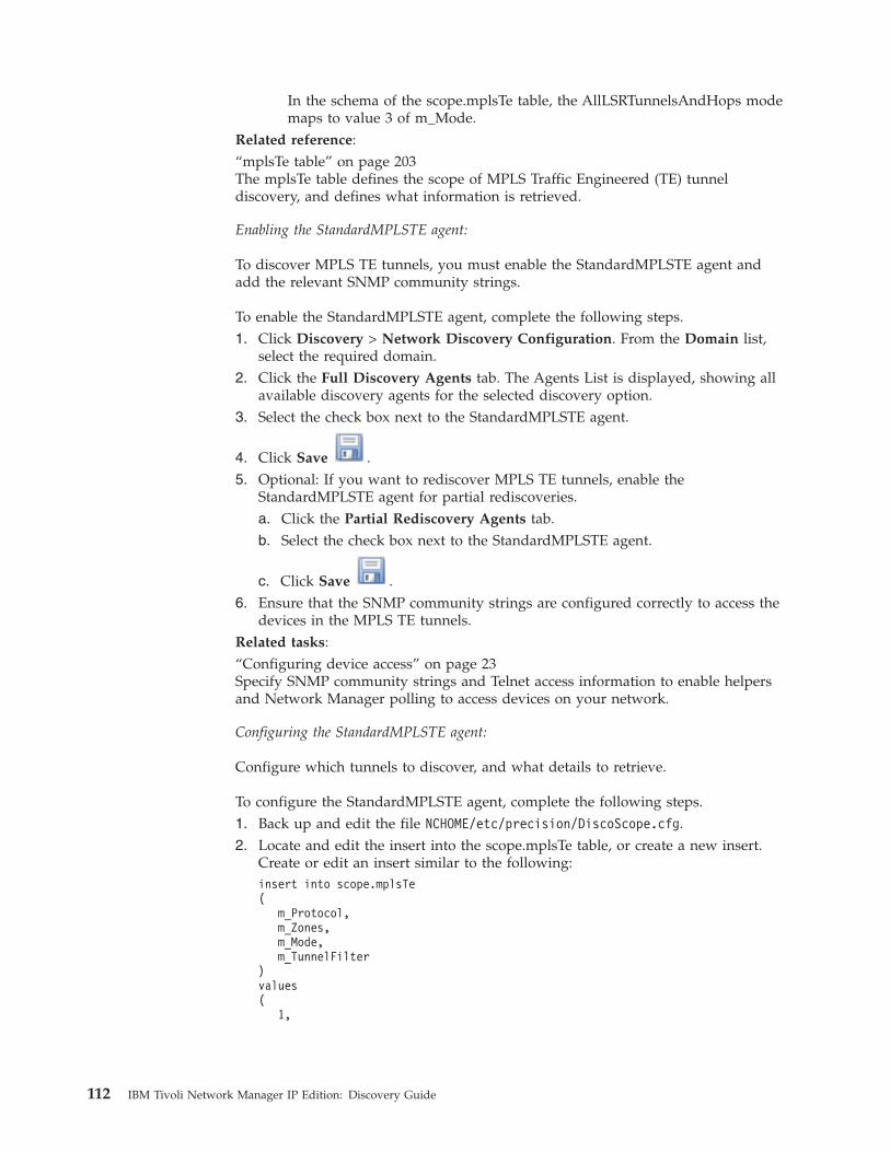
In the schema of the scope.mplsTe table, the AllLSRTunnelsAndHops modemaps to value 3 of m_Mode.
Related reference:“mplsTe table” on page 203The mplsTe table defines the scope of MPLS Traffic Engineered (TE) tunneldiscovery, and defines what information is retrieved.
Enabling the StandardMPLSTE agent:
To discover MPLS TE tunnels, you must enable the StandardMPLSTE agent andadd the relevant SNMP community strings.
To enable the StandardMPLSTE agent, complete the following steps.1. Click Discovery > Network Discovery Configuration. From the Domain list,
select the required domain.2. Click the Full Discovery Agents tab. The Agents List is displayed, showing all
available discovery agents for the selected discovery option.3. Select the check box next to the StandardMPLSTE agent.
4. Click Save .5. Optional: If you want to rediscover MPLS TE tunnels, enable the
StandardMPLSTE agent for partial rediscoveries.a. Click the Partial Rediscovery Agents tab.b. Select the check box next to the StandardMPLSTE agent.
c. Click Save .6. Ensure that the SNMP community strings are configured correctly to access the
devices in the MPLS TE tunnels.Related tasks:“Configuring device access” on page 23Specify SNMP community strings and Telnet access information to enable helpersand Network Manager polling to access devices on your network.
Configuring the StandardMPLSTE agent:
Configure which tunnels to discover, and what details to retrieve.
To configure the StandardMPLSTE agent, complete the following steps.1. Back up and edit the file NCHOME/etc/precision/DiscoScope.cfg.2. Locate and edit the insert into the scope.mplsTe table, or create a new insert.
Create or edit an insert similar to the following:insert into scope.mplsTe(
m_Protocol,m_Zones,m_Mode,m_TunnelFilter
)values(
1,
112 IBM Tivoli Network Manager IP Edition: Discovery Guide
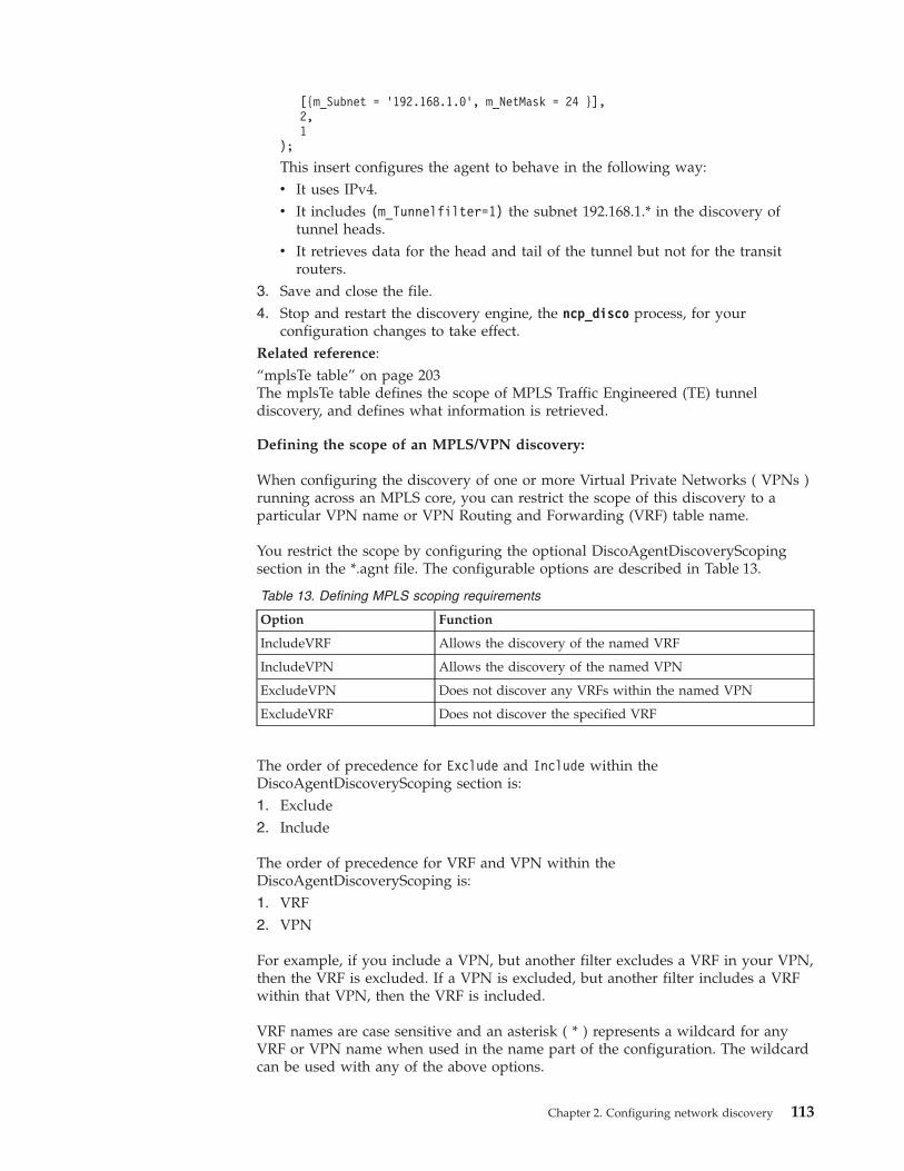
[{m_Subnet = ’192.168.1.0’, m_NetMask = 24 }],2,1
);
This insert configures the agent to behave in the following way:v It uses IPv4.v It includes (m_Tunnelfilter=1) the subnet 192.168.1.* in the discovery of
tunnel heads.v It retrieves data for the head and tail of the tunnel but not for the transit
routers.3. Save and close the file.4. Stop and restart the discovery engine, the ncp_disco process, for your
configuration changes to take effect.Related reference:“mplsTe table” on page 203The mplsTe table defines the scope of MPLS Traffic Engineered (TE) tunneldiscovery, and defines what information is retrieved.
Defining the scope of an MPLS/VPN discovery:
When configuring the discovery of one or more Virtual Private Networks ( VPNs )running across an MPLS core, you can restrict the scope of this discovery to aparticular VPN name or VPN Routing and Forwarding (VRF) table name.
You restrict the scope by configuring the optional DiscoAgentDiscoveryScopingsection in the *.agnt file. The configurable options are described in Table 13.
Table 13. Defining MPLS scoping requirements
Option Function
IncludeVRF Allows the discovery of the named VRF
IncludeVPN Allows the discovery of the named VPN
ExcludeVPN Does not discover any VRFs within the named VPN
ExcludeVRF Does not discover the specified VRF
The order of precedence for Exclude and Include within theDiscoAgentDiscoveryScoping section is:1. Exclude2. Include
The order of precedence for VRF and VPN within theDiscoAgentDiscoveryScoping is:1. VRF2. VPN
For example, if you include a VPN, but another filter excludes a VRF in your VPN,then the VRF is excluded. If a VPN is excluded, but another filter includes a VRFwithin that VPN, then the VRF is included.
VRF names are case sensitive and an asterisk ( * ) represents a wildcard for anyVRF or VPN name when used in the name part of the configuration. The wildcardcan be used with any of the above options.
Chapter 2. Configuring network discovery 113
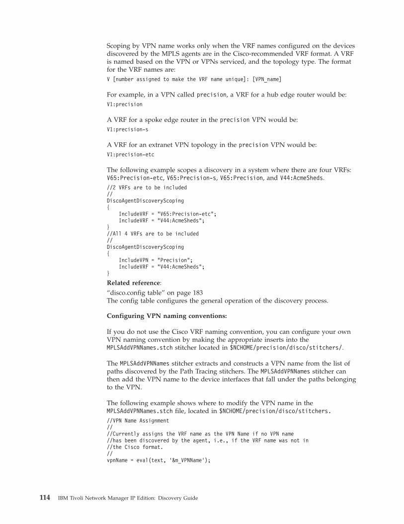
Scoping by VPN name works only when the VRF names configured on the devicesdiscovered by the MPLS agents are in the Cisco-recommended VRF format. A VRFis named based on the VPN or VPNs serviced, and the topology type. The formatfor the VRF names are:V [number assigned to make the VRF name unique]: [VPN_name]
For example, in a VPN called precision, a VRF for a hub edge router would be:V1:precision
A VRF for a spoke edge router in the precision VPN would be:V1:precision-s
A VRF for an extranet VPN topology in the precision VPN would be:V1:precision-etc
The following example scopes a discovery in a system where there are four VRFs:V65:Precision-etc, V65:Precision-s, V65:Precision, and V44:AcmeSheds.//2 VRFs are to be included//DiscoAgentDiscoveryScoping{
IncludeVRF = “V65:Precision-etc”;IncludeVRF = “V44:AcmeSheds”;
}//All 4 VRFs are to be included//DiscoAgentDiscoveryScoping{
IncludeVPN = “Precision”;IncludeVRF = “V44:AcmeSheds”;
}
Related reference:“disco.config table” on page 183The config table configures the general operation of the discovery process.
Configuring VPN naming conventions:
If you do not use the Cisco VRF naming convention, you can configure your ownVPN naming convention by making the appropriate inserts into theMPLSAddVPNNames.stch stitcher located in $NCHOME/precision/disco/stitchers/.
The MPLSAddVPNNames stitcher extracts and constructs a VPN name from the list ofpaths discovered by the Path Tracing stitchers. The MPLSAddVPNNames stitcher canthen add the VPN name to the device interfaces that fall under the paths belongingto the VPN.
The following example shows where to modify the VPN name in theMPLSAddVPNNames.stch file, located in $NCHOME/precision/disco/stitchers.
//VPN Name Assignment////Currently assigns the VRF name as the VPN Name if no VPN name//has been discovered by the agent, i.e., if the VRF name was not in//the Cisco format.//vpnName = eval(text, '&m_VPNName’);
114 IBM Tivoli Network Manager IP Edition: Discovery Guide

if (vpnName == NULL){
vpnName = vrfName; //VPN=VRF, customize as required.}
Fine-tuning label data:
The MPLS discovery method (RT-based or LSP-based) determines whether theMPLS agents retrieve MPLS label data.v If you choose RT-based discovery, the MPLS agents do not retrieve label data.v If you choose LSP-based discovery, the MPLS agents retrieve label data.
If you choose an RT-based discovery, but want to retrieve label data, it is possibleto do this manually with the following insert in the DiscoAgentDiscoveryScopingsection of the appropriate MPLS.agnt file:DiscoAgentDiscoveryScoping{
GetMPLSLabelData = 1;}
Related tasks:“Configuring MPLS discovery method” on page 108You can configure MPLS discovery in either of two ways: Route Target (RT)-baseddiscovery; Label Switched Path (LSP)-based discovery.
Configuring NAT discoveriesConfigure a Network Address Translation (NAT) discovery to discover NATenvironments, by mapping the address-space identifier for a NAT domain to the IPaddress of the associated NAT gateway device.
About Network Address TranslationThe number of available IP addresses in the current 32–bit format is not enough tomeet the growth in demand for access to the Internet. Network AddressTranslation (NAT) was designed as a short-term solution to this problem byproviding a method of connecting multiple computers to an IP network usingeither a single unique public IP address, or a small number of unique public IPaddresses.
NAT is commonly used in corporations, where a NAT router sits at the edge of theprivate network (referred to in this context as a stub domain) and translates the IPaddresses attached to packets entering and leaving the stub domain. The NATrouter, which effectively acts as an agent between the Internet and the localnetwork, maintains a list of the mappings between public and private addresses.
Note: A stub domain is a local network using internal IP addresses. The networkcan use unregistered, private, IP addresses for internal communication—theseaddresses must be translated into unique, public, IP addresses whencommunicating outside the network. The addresses used internally by a given stubdomain can also be used internally by any other stub domain.
For example, when a computer within the private network requests informationfrom the public network, the NAT router automatically translates the privateaddress of that computer into the public address of the domain, which is the onlyaddress that is transmitted to the public network. When the requested informationis returned, the NAT router consults its internal list of public to private addressmappings in order to forward the information to the appropriate computer.
Chapter 2. Configuring network discovery 115
There are a number of different ways to configure a NAT environment. Thefollowing descriptions detail the most common types of NAT environment.
Static NAT Environments:
In a static NAT environment, the NAT router maps private and public addresseson a one-to-one basis, that is, the private address of a given device always maps tothe same public address. This type of NAT environment is commonly used fordevices that need to be accessible to the public network.
Dynamic NAT environments:
In a dynamic NAT environment, the NAT router dynamically allocates public IPaddresses, from a group of addresses, to devices on the private network that wishto communicate with the public network. A variation on dynamic NAT, overloadingor PAT (Port Address Translation), maps multiple private addresses to the samepublic address using different ports.
Private Address Ranges:
The Internet Assigned Numbers Authority (IANA) has assigned several addressranges to be used by private networks.
Address ranges to be use by private networks are:v Class A: 10.0.0.0 to 10.255.255.255
v Class B: 172.16.0.0 to 172.31.255.255
v Class C: 192.168.0.0 to 192.168.255.255
An IP address within these ranges is therefore considered non-routable, as it is notunique. Any private network that needs to use IP addresses internally can use anyaddress within these ranges without any coordination with IANA or an Internetregistry. Addresses within this private address space are only unique within agiven private network.
All addresses outside these ranges are considered public.
About NAT discoveryYou can use Network Manager to manage NAT environments, though there aresome restrictions on the types of NAT environment that are currently supported.
Network Manager can interrogate known, supported NAT gateways to obtain a listof public to private IP address mappings of devices in NAT domains. Alternatively,these mappings can be supplied manually. Network Manager can then discoverthose devices behind the NAT gateways that have a public IP address.
Each NAT domain has a unique address-space identifier. Each device in a NATdomain has the appropriate address-space identifier appended to its record. Thisenables the devices to be managed (for example, polled).
116 IBM Tivoli Network Manager IP Edition: Discovery Guide
Restrictions on NAT discovery:
There are several restrictions on the management of NAT environments usingNetwork Manager.
Management of NAT environments using Network Manager is restricted by thefollowing conditions:v Network Manager can discover one or more NAT environments, but they must
all use static NAT address mapping.v Network Manager can discover devices in multiple NAT domains, regardless of
whether the private IP addresses of the devices are duplicated in other NATdomains. However, the public IP address of each device in each domain must beunique.
v Devices within a NAT domain that have only private IP addresses cannot bediscovered or managed by Network Manager.
v The discovery process must discover the NAT environment from outside, that is,from the public network.
v Virtual IP addresses such as Hot Standby Routing Protocol (HSRP) addressescannot be mapped. The real physical address must be used.
v The following must be supplied before the discovery is run:– The addresses of all supported NAT gateways.– The NAT gateway translations must be discovered, either automatically or by
supplying the NATTextFileAgent discovery agent with a flat file ofpublic-to-private IP address mappings.
Differences in a NAT discovery process flow:
The process flow of a NAT discovery differs from the process flow of a normaldiscovery.Related concepts:“Discovery cycles” on page 285A discovery cycle has occurred when the discovery data flow for a particular cyclehas gone from start to finish. A full discovery might require more than one cycle.
Downloading translation information:
NAT translation information is downloaded by the NAT agents into thetranslations.NATTemp database table before the finders process any other entities.
All other discovered devices are inserted into the finders.pending table while theBuildNATTranslation.stch stitcher creates a global translation table and stores it inthe translations.NAT database table.
The finders, helpers, and other components that need to access devices can use thistable to look up the address of any device behind a NAT gateway.
Chapter 2. Configuring network discovery 117
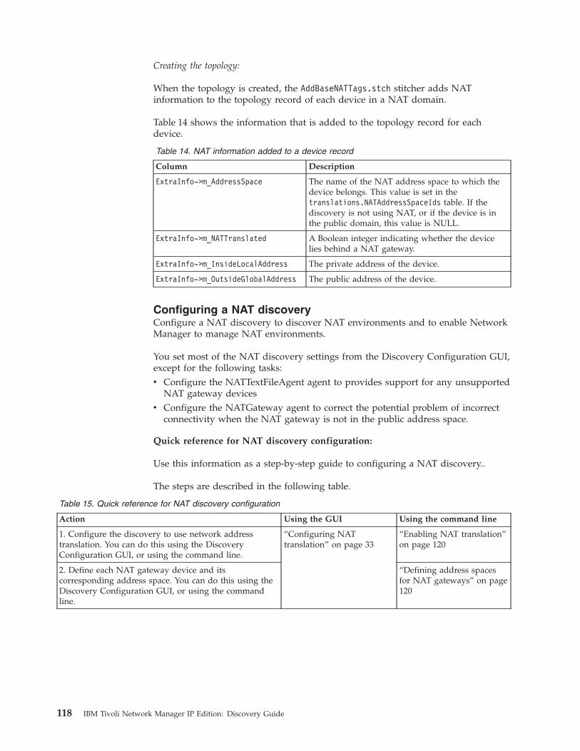
Creating the topology:
When the topology is created, the AddBaseNATTags.stch stitcher adds NATinformation to the topology record of each device in a NAT domain.
Table 14 shows the information that is added to the topology record for eachdevice.
Table 14. NAT information added to a device record
Column Description
ExtraInfo->m_AddressSpace The name of the NAT address space to which thedevice belongs. This value is set in thetranslations.NATAddressSpaceIds table. If thediscovery is not using NAT, or if the device is inthe public domain, this value is NULL.
ExtraInfo->m_NATTranslated A Boolean integer indicating whether the devicelies behind a NAT gateway.
ExtraInfo->m_InsideLocalAddress The private address of the device.
ExtraInfo->m_OutsideGlobalAddress The public address of the device.
Configuring a NAT discoveryConfigure a NAT discovery to discover NAT environments and to enable NetworkManager to manage NAT environments.
You set most of the NAT discovery settings from the Discovery Configuration GUI,except for the following tasks:v Configure the NATTextFileAgent agent to provides support for any unsupported
NAT gateway devicesv Configure the NATGateway agent to correct the potential problem of incorrect
connectivity when the NAT gateway is not in the public address space.
Quick reference for NAT discovery configuration:
Use this information as a step-by-step guide to configuring a NAT discovery..
The steps are described in the following table.
Table 15. Quick reference for NAT discovery configuration
Action Using the GUI Using the command line
1. Configure the discovery to use network addresstranslation. You can do this using the DiscoveryConfiguration GUI, or using the command line.
“Configuring NATtranslation” on page 33
“Enabling NAT translation”on page 120
2. Define each NAT gateway device and itscorresponding address space. You can do this using theDiscovery Configuration GUI, or using the commandline.
“Defining address spacesfor NAT gateways” on page120
118 IBM Tivoli Network Manager IP Edition: Discovery Guide
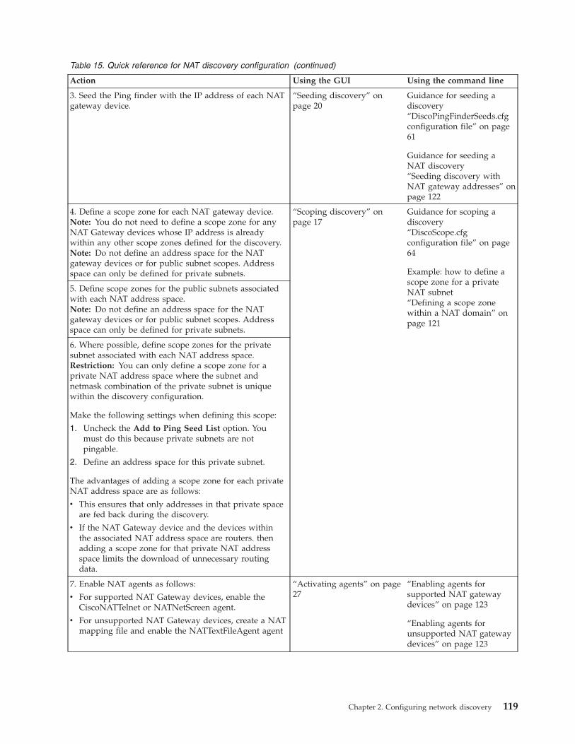
Table 15. Quick reference for NAT discovery configuration (continued)
Action Using the GUI Using the command line
3. Seed the Ping finder with the IP address of each NATgateway device.
“Seeding discovery” onpage 20
Guidance for seeding adiscovery“DiscoPingFinderSeeds.cfgconfiguration file” on page61
Guidance for seeding aNAT discovery“Seeding discovery withNAT gateway addresses” onpage 122
4. Define a scope zone for each NAT gateway device.Note: You do not need to define a scope zone for anyNAT Gateway devices whose IP address is alreadywithin any other scope zones defined for the discovery.Note: Do not define an address space for the NATgateway devices or for public subnet scopes. Addressspace can only be defined for private subnets.
“Scoping discovery” onpage 17
Guidance for scoping adiscovery“DiscoScope.cfgconfiguration file” on page64
Example: how to define ascope zone for a privateNAT subnet“Defining a scope zonewithin a NAT domain” onpage 121
5. Define scope zones for the public subnets associatedwith each NAT address space.Note: Do not define an address space for the NATgateway devices or for public subnet scopes. Addressspace can only be defined for private subnets.
6. Where possible, define scope zones for the privatesubnet associated with each NAT address space.Restriction: You can only define a scope zone for aprivate NAT address space where the subnet andnetmask combination of the private subnet is uniquewithin the discovery configuration.
Make the following settings when defining this scope:
1. Uncheck the Add to Ping Seed List option. Youmust do this because private subnets are notpingable.
2. Define an address space for this private subnet.
The advantages of adding a scope zone for each privateNAT address space are as follows:
v This ensures that only addresses in that private spaceare fed back during the discovery.
v If the NAT Gateway device and the devices withinthe associated NAT address space are routers. thenadding a scope zone for that private NAT addressspace limits the download of unnecessary routingdata.
7. Enable NAT agents as follows:
v For supported NAT Gateway devices, enable theCiscoNATTelnet or NATNetScreen agent.
v For unsupported NAT Gateway devices, create a NATmapping file and enable the NATTextFileAgent agent
“Activating agents” on page27
“Enabling agents forsupported NAT gatewaydevices” on page 123
“Enabling agents forunsupported NAT gatewaydevices” on page 123
Chapter 2. Configuring network discovery 119
Related tasks:“Example: Configuring a NAT discovery” on page 125This example illustrates how to define address spaces using the NATTextFileAgentagent and how to set up associated discovery scopes.
Enabling NAT translation:
You can set the discovery system to use NAT translation by editing$NCHOME/etc/precision/DiscoConfig.cfg to create or amend an insert intodisco.NATStatus to set m_UsingNAT to 1 and m_NATStatus to 0.
The completed insert must resemble the following:insert into disco.NATStatus(
m_UsingNAT,m_NATStatus
)values(
1,0
);
Related tasks:“Configuring NAT translation” on page 33To configure NAT translation to discover NAT environments, map theaddress-space identifier for a NAT domain to the IP address of the associated NATgateway device.“Enabling NAT translation”You can set the discovery system to use NAT translation by editing$NCHOME/etc/precision/DiscoConfig.cfg to create or amend an insert intodisco.NATStatus to set m_UsingNAT to 1 and m_NATStatus to 0.
Defining address spaces for NAT gateways:
To specify the IP address of your NAT gateways and the address space identifieryou want to use for each associated NAT domain, edit DiscoConfig.cfg to createor amend an insert into translations.NATAddressSpaceIds.
Follow these guidelines when defining address spaces for NAT gateways:v The IP address must be the public IP address that is accessible from the
management server.v The address space field can be any descriptive string, but avoid special
characters such as quotes. Use the standard rules for DNS names for the addressspace because the address space might make up part of the name of thesedevices.
The following example insert configures the discovery system for two NATgateways.insert into translations.NATAddressSpaceIds(
m_NATGatewayIP,m_AddressSpaceId
)values(
’172.16.1.112’,’NATDomain1’
120 IBM Tivoli Network Manager IP Edition: Discovery Guide
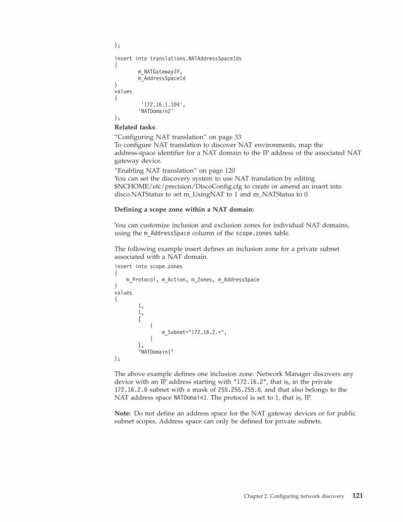
);
insert into translations.NATAddressSpaceIds(
m_NATGatewayIP,m_AddressSpaceId
)values(
’172.16.1.104’,’NATDomain2’
);
Related tasks:“Configuring NAT translation” on page 33To configure NAT translation to discover NAT environments, map theaddress-space identifier for a NAT domain to the IP address of the associated NATgateway device.“Enabling NAT translation” on page 120You can set the discovery system to use NAT translation by editing$NCHOME/etc/precision/DiscoConfig.cfg to create or amend an insert intodisco.NATStatus to set m_UsingNAT to 1 and m_NATStatus to 0.
Defining a scope zone within a NAT domain:
You can customize inclusion and exclusion zones for individual NAT domains,using the m_AddressSpace column of the scope.zones table.
The following example insert defines an inclusion zone for a private subnetassociated with a NAT domain.insert into scope.zones(
m_Protocol, m_Action, m_Zones, m_AddressSpace)values(
1,1,[
{m_Subnet="172.16.2.*",
}],"NATDomain1"
);
The above example defines one inclusion zone. Network Manager discovers anydevice with an IP address starting with "172.16.2", that is, in the private172.16.2.0 subnet with a mask of 255.255.255.0, and that also belongs to theNAT address space NATDomain1. The protocol is set to 1, that is, IP.
Note: Do not define an address space for the NAT gateway devices or for publicsubnet scopes. Address space can only be defined for private subnets.
Chapter 2. Configuring network discovery 121
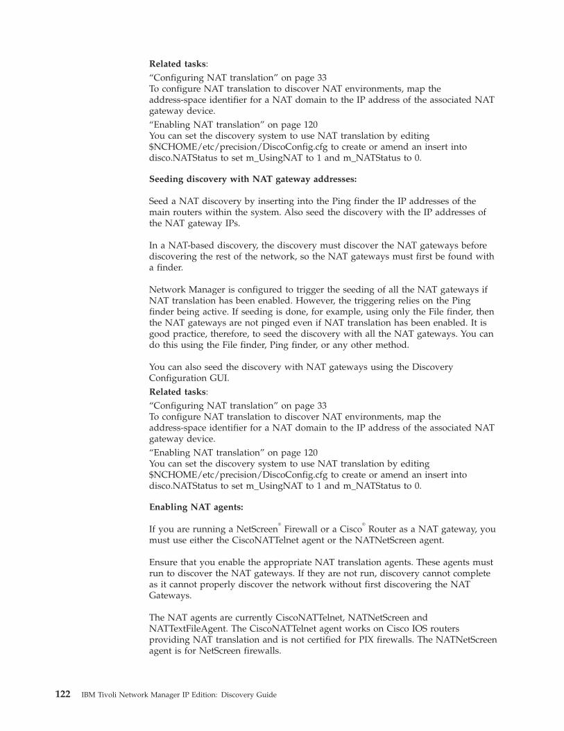
Related tasks:“Configuring NAT translation” on page 33To configure NAT translation to discover NAT environments, map theaddress-space identifier for a NAT domain to the IP address of the associated NATgateway device.“Enabling NAT translation” on page 120You can set the discovery system to use NAT translation by editing$NCHOME/etc/precision/DiscoConfig.cfg to create or amend an insert intodisco.NATStatus to set m_UsingNAT to 1 and m_NATStatus to 0.
Seeding discovery with NAT gateway addresses:
Seed a NAT discovery by inserting into the Ping finder the IP addresses of themain routers within the system. Also seed the discovery with the IP addresses ofthe NAT gateway IPs.
In a NAT-based discovery, the discovery must discover the NAT gateways beforediscovering the rest of the network, so the NAT gateways must first be found witha finder.
Network Manager is configured to trigger the seeding of all the NAT gateways ifNAT translation has been enabled. However, the triggering relies on the Pingfinder being active. If seeding is done, for example, using only the File finder, thenthe NAT gateways are not pinged even if NAT translation has been enabled. It isgood practice, therefore, to seed the discovery with all the NAT gateways. You cando this using the File finder, Ping finder, or any other method.
You can also seed the discovery with NAT gateways using the DiscoveryConfiguration GUI.Related tasks:“Configuring NAT translation” on page 33To configure NAT translation to discover NAT environments, map theaddress-space identifier for a NAT domain to the IP address of the associated NATgateway device.“Enabling NAT translation” on page 120You can set the discovery system to use NAT translation by editing$NCHOME/etc/precision/DiscoConfig.cfg to create or amend an insert intodisco.NATStatus to set m_UsingNAT to 1 and m_NATStatus to 0.
Enabling NAT agents:
If you are running a NetScreen®
Firewall or a Cisco®
Router as a NAT gateway, youmust use either the CiscoNATTelnet agent or the NATNetScreen agent.
Ensure that you enable the appropriate NAT translation agents. These agents mustrun to discover the NAT gateways. If they are not run, discovery cannot completeas it cannot properly discover the network without first discovering the NATGateways.
The NAT agents are currently CiscoNATTelnet, NATNetScreen andNATTextFileAgent. The CiscoNATTelnet agent works on Cisco IOS routersproviding NAT translation and is not certified for PIX firewalls. The NATNetScreenagent is for NetScreen firewalls.
122 IBM Tivoli Network Manager IP Edition: Discovery Guide
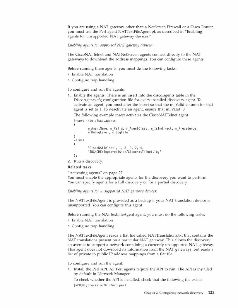
If you are using a NAT gateway other than a NetScreen Firewall or a Cisco Router,you must use the Perl agent NATTextFileAgent.pl, as described in “Enablingagents for unsupported NAT gateway devices.”
Enabling agents for supported NAT gateway devices:
The CiscoNATTelnet and NATNetScreen agents connect directly to the NATgateways to download the address mappings. You can configure these agents.
Before running these agents, you must do the following tasks:v Enable NAT translationv Configure trap handling
To configure and run the agents:1. Enable the agents. There is an insert into the disco.agents table in the
DiscoAgents.cfg configuration file for every installed discovery agent. Toactivate an agent, you must alter the insert so that the m_Valid column for thatagent is set to 1. To deactivate an agent, ensure that m_Valid=0.The following example insert activates the CiscoNATTelnet agent.insert into disco.agents(
m_AgentName, m_Valid, m_AgentClass, m_IsIndirect, m_Precedence,m_DebugLevel, m_LogFile
)values(
’CiscoNATTelnet’, 1, 8, 0, 2, 4,"$NCHOME/log/precision/CiscoNatTelnet.log"
);
2. Run a discovery.Related tasks:“Activating agents” on page 27You must enable the appropriate agents for the discovery you want to perform.You can specify agents for a full discovery or for a partial discovery.
Enabling agents for unsupported NAT gateway devices:
The NATTextFileAgent is provided as a backup if your NAT translation device isunsupported. You can configure this agent.
Before running the NATTextFileAgent agent, you must do the following tasks:v Enable NAT translationv Configure trap handling
The NATTextFileAgent reads a flat file called NATTranslations.txt that contains theNAT translations present on a particular NAT gateway. This allows the discoveryan avenue to support a network containing a currently unsupported NAT gateway.This agent does not download its information from the NAT gateways, but reads alist of private to public IP address mappings from a flat file.
To configure and run the agent:1. Install the Perl API. All Perl agents require the API to run. The API is installed
by default in Network Manager.To check whether the API is installed, check that the following file exists:$NCHOME/precision/bin/ncp_perl
Chapter 2. Configuring network discovery 123
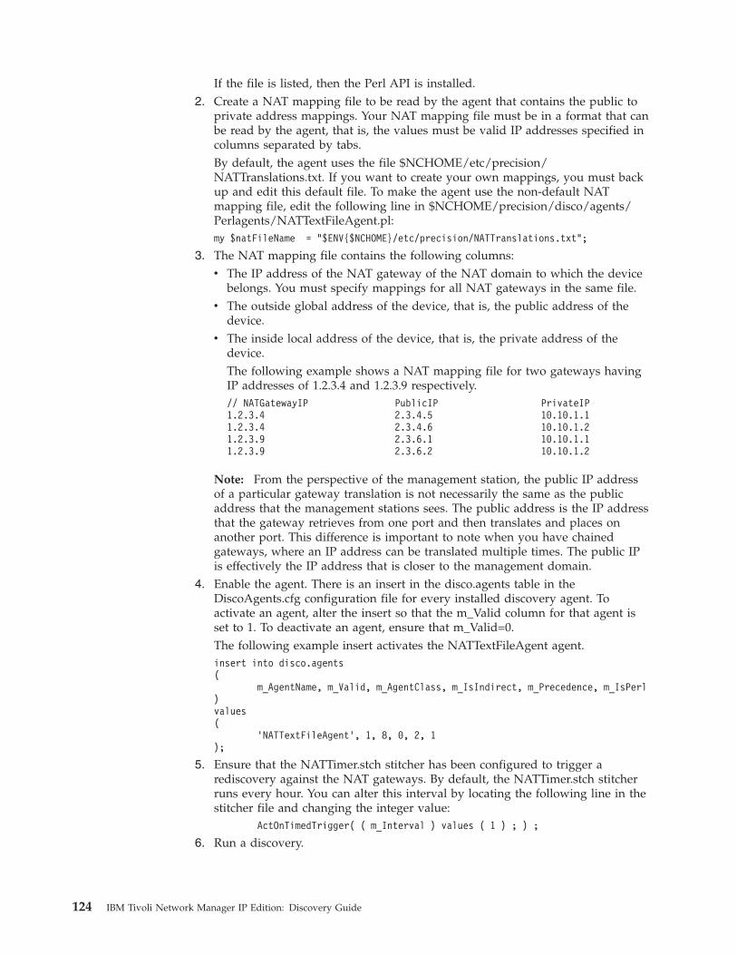
If the file is listed, then the Perl API is installed.2. Create a NAT mapping file to be read by the agent that contains the public to
private address mappings. Your NAT mapping file must be in a format that canbe read by the agent, that is, the values must be valid IP addresses specified incolumns separated by tabs.By default, the agent uses the file $NCHOME/etc/precision/NATTranslations.txt. If you want to create your own mappings, you must backup and edit this default file. To make the agent use the non-default NATmapping file, edit the following line in $NCHOME/precision/disco/agents/Perlagents/NATTextFileAgent.pl:my $natFileName = "$ENV{$NCHOME}/etc/precision/NATTranslations.txt";
3. The NAT mapping file contains the following columns:v The IP address of the NAT gateway of the NAT domain to which the device
belongs. You must specify mappings for all NAT gateways in the same file.v The outside global address of the device, that is, the public address of the
device.v The inside local address of the device, that is, the private address of the
device.The following example shows a NAT mapping file for two gateways havingIP addresses of 1.2.3.4 and 1.2.3.9 respectively.// NATGatewayIP PublicIP PrivateIP1.2.3.4 2.3.4.5 10.10.1.11.2.3.4 2.3.4.6 10.10.1.21.2.3.9 2.3.6.1 10.10.1.11.2.3.9 2.3.6.2 10.10.1.2
Note: From the perspective of the management station, the public IP addressof a particular gateway translation is not necessarily the same as the publicaddress that the management stations sees. The public address is the IP addressthat the gateway retrieves from one port and then translates and places onanother port. This difference is important to note when you have chainedgateways, where an IP address can be translated multiple times. The public IPis effectively the IP address that is closer to the management domain.
4. Enable the agent. There is an insert in the disco.agents table in theDiscoAgents.cfg configuration file for every installed discovery agent. Toactivate an agent, alter the insert so that the m_Valid column for that agent isset to 1. To deactivate an agent, ensure that m_Valid=0.The following example insert activates the NATTextFileAgent agent.insert into disco.agents(
m_AgentName, m_Valid, m_AgentClass, m_IsIndirect, m_Precedence, m_IsPerl)values(
’NATTextFileAgent’, 1, 8, 0, 2, 1);
5. Ensure that the NATTimer.stch stitcher has been configured to trigger arediscovery against the NAT gateways. By default, the NATTimer.stch stitcherruns every hour. You can alter this interval by locating the following line in thestitcher file and changing the integer value:
ActOnTimedTrigger( ( m_Interval ) values ( 1 ) ; ) ;
6. Run a discovery.
124 IBM Tivoli Network Manager IP Edition: Discovery Guide
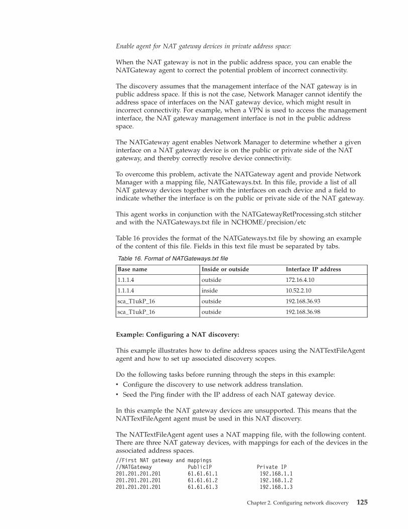
Enable agent for NAT gateway devices in private address space:
When the NAT gateway is not in the public address space, you can enable theNATGateway agent to correct the potential problem of incorrect connectivity.
The discovery assumes that the management interface of the NAT gateway is inpublic address space. If this is not the case, Network Manager cannot identify theaddress space of interfaces on the NAT gateway device, which might result inincorrect connectivity. For example, when a VPN is used to access the managementinterface, the NAT gateway management interface is not in the public addressspace.
The NATGateway agent enables Network Manager to determine whether a giveninterface on a NAT gateway device is on the public or private side of the NATgateway, and thereby correctly resolve device connectivity.
To overcome this problem, activate the NATGateway agent and provide NetworkManager with a mapping file, NATGateways.txt. In this file, provide a list of allNAT gateway devices together with the interfaces on each device and a field toindicate whether the interface is on the public or private side of the NAT gateway.
This agent works in conjunction with the NATGatewayRetProcessing.stch stitcherand with the NATGateways.txt file in NCHOME/precision/etc
Table 16 provides the format of the NATGateways.txt file by showing an exampleof the content of this file. Fields in this text file must be separated by tabs.
Table 16. Format of NATGateways.txt file
Base name Inside or outside Interface IP address
1.1.1.4 outside 172.16.4.10
1.1.1.4 inside 10.52.2.10
sca_T1ukP_16 outside 192.168.36.93
sca_T1ukP_16 outside 192.168.36.98
Example: Configuring a NAT discovery:
This example illustrates how to define address spaces using the NATTextFileAgentagent and how to set up associated discovery scopes.
Do the following tasks before running through the steps in this example:v Configure the discovery to use network address translation.v Seed the Ping finder with the IP address of each NAT gateway device.
In this example the NAT gateway devices are unsupported. This means that theNATTextFileAgent agent must be used in this NAT discovery.
The NATTextFileAgent agent uses a NAT mapping file, with the following content.There are three NAT gateway devices, with mappings for each of the devices in theassociated address spaces.//First NAT gateway and mappings//NATGateway PublicIP Private IP201.201.201.201 61.61.61.1 192.168.1.1201.201.201.201 61.61.61.2 192.168.1.2201.201.201.201 61.61.61.3 192.168.1.3
Chapter 2. Configuring network discovery 125
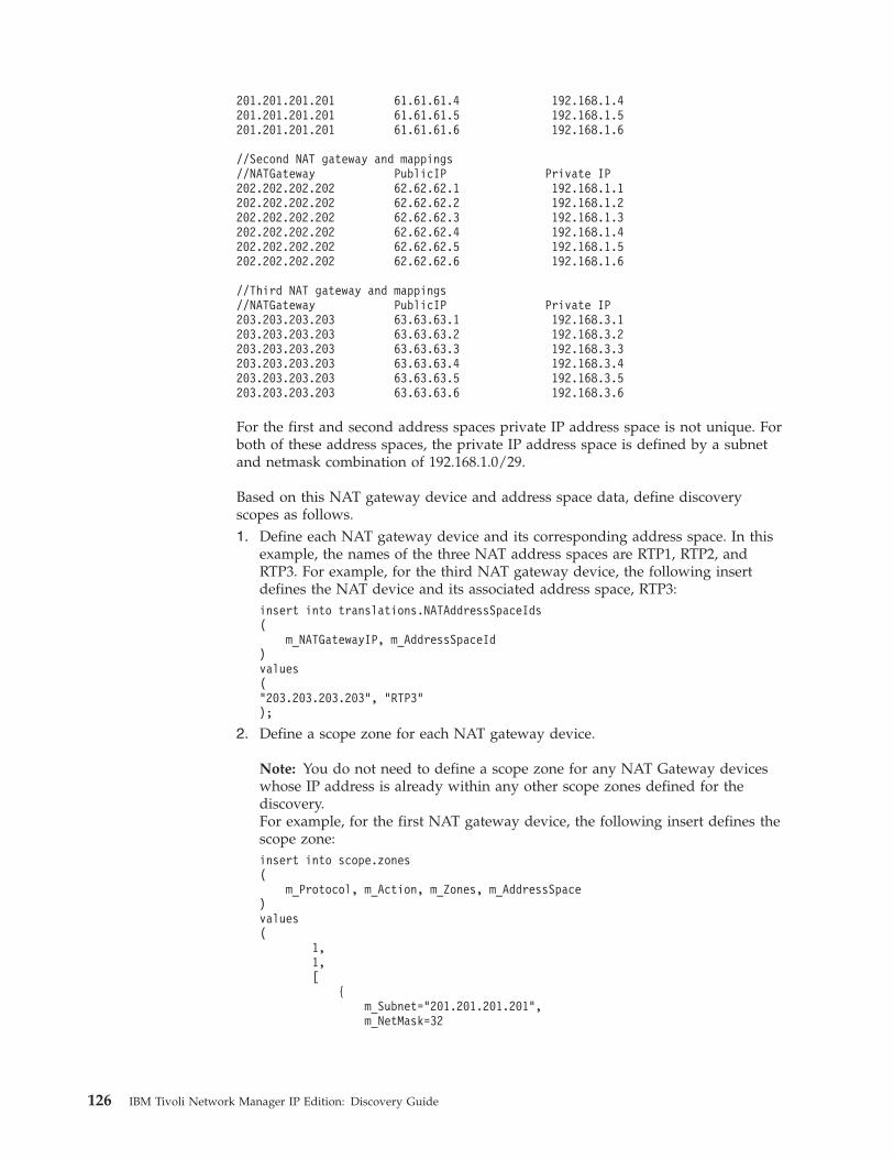
201.201.201.201 61.61.61.4 192.168.1.4201.201.201.201 61.61.61.5 192.168.1.5201.201.201.201 61.61.61.6 192.168.1.6
//Second NAT gateway and mappings//NATGateway PublicIP Private IP202.202.202.202 62.62.62.1 192.168.1.1202.202.202.202 62.62.62.2 192.168.1.2202.202.202.202 62.62.62.3 192.168.1.3202.202.202.202 62.62.62.4 192.168.1.4202.202.202.202 62.62.62.5 192.168.1.5202.202.202.202 62.62.62.6 192.168.1.6
//Third NAT gateway and mappings//NATGateway PublicIP Private IP203.203.203.203 63.63.63.1 192.168.3.1203.203.203.203 63.63.63.2 192.168.3.2203.203.203.203 63.63.63.3 192.168.3.3203.203.203.203 63.63.63.4 192.168.3.4203.203.203.203 63.63.63.5 192.168.3.5203.203.203.203 63.63.63.6 192.168.3.6
For the first and second address spaces private IP address space is not unique. Forboth of these address spaces, the private IP address space is defined by a subnetand netmask combination of 192.168.1.0/29.
Based on this NAT gateway device and address space data, define discoveryscopes as follows.1. Define each NAT gateway device and its corresponding address space. In this
example, the names of the three NAT address spaces are RTP1, RTP2, andRTP3. For example, for the third NAT gateway device, the following insertdefines the NAT device and its associated address space, RTP3:insert into translations.NATAddressSpaceIds(
m_NATGatewayIP, m_AddressSpaceId)values("203.203.203.203", "RTP3");
2. Define a scope zone for each NAT gateway device.
Note: You do not need to define a scope zone for any NAT Gateway deviceswhose IP address is already within any other scope zones defined for thediscovery.For example, for the first NAT gateway device, the following insert defines thescope zone:insert into scope.zones(
m_Protocol, m_Action, m_Zones, m_AddressSpace)values(
1,1,[
{m_Subnet="201.201.201.201",m_NetMask=32
126 IBM Tivoli Network Manager IP Edition: Discovery Guide
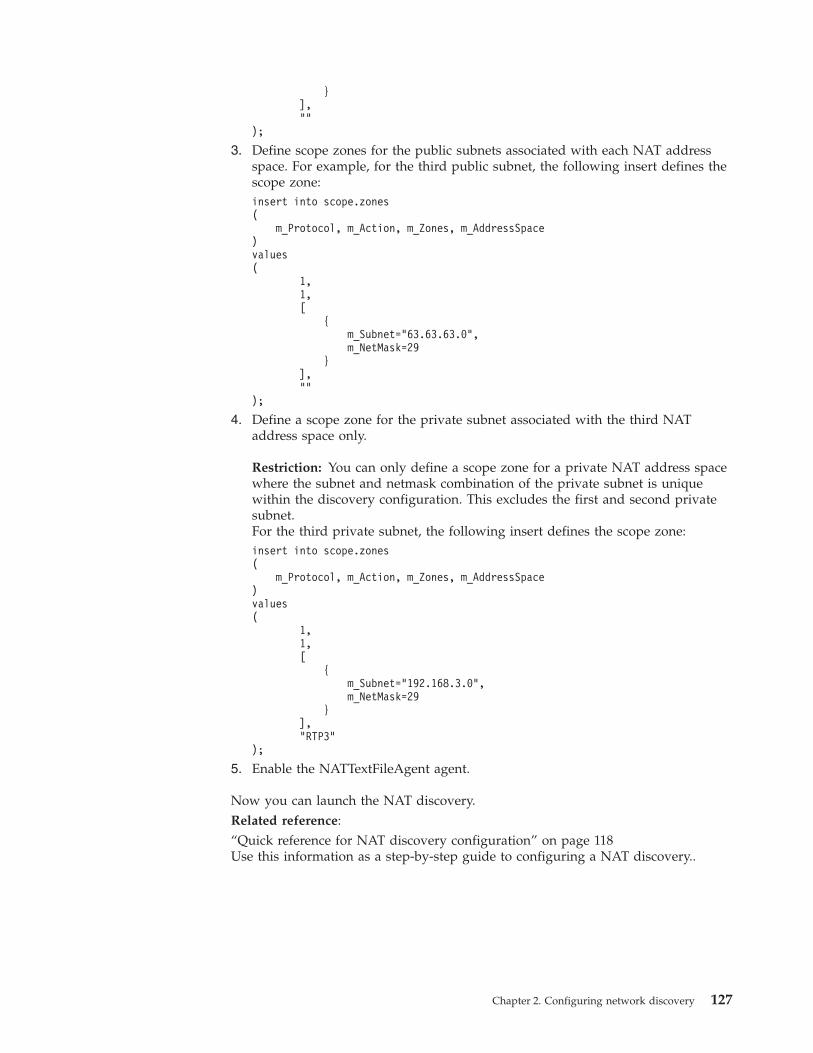
}],""
);
3. Define scope zones for the public subnets associated with each NAT addressspace. For example, for the third public subnet, the following insert defines thescope zone:insert into scope.zones(
m_Protocol, m_Action, m_Zones, m_AddressSpace)values(
1,1,[
{m_Subnet="63.63.63.0",m_NetMask=29
}],""
);
4. Define a scope zone for the private subnet associated with the third NATaddress space only.
Restriction: You can only define a scope zone for a private NAT address spacewhere the subnet and netmask combination of the private subnet is uniquewithin the discovery configuration. This excludes the first and second privatesubnet.For the third private subnet, the following insert defines the scope zone:insert into scope.zones(
m_Protocol, m_Action, m_Zones, m_AddressSpace)values(
1,1,[
{m_Subnet="192.168.3.0",m_NetMask=29
}],"RTP3"
);
5. Enable the NATTextFileAgent agent.
Now you can launch the NAT discovery.Related reference:“Quick reference for NAT discovery configuration” on page 118Use this information as a step-by-step guide to configuring a NAT discovery..
Chapter 2. Configuring network discovery 127
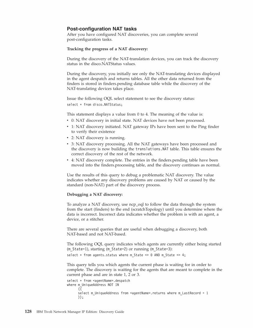
Post-configuration NAT tasksAfter you have configured NAT discoveries, you can complete severalpost-configuration tasks.
Tracking the progress of a NAT discovery:
During the discovery of the NAT-translation devices, you can track the discoverystatus in the disco.NATStatus values.
During the discovery, you initially see only the NAT-translating devices displayedin the agent despatch and returns tables. All the other data returned from thefinders is stored in finders.pending database table while the discovery of theNAT-translating devices takes place.
Issue the following OQL select statement to see the discovery status:select * from disco.NATStatus;
This statement displays a value from 0 to 4. The meaning of the value is:v 0: NAT discovery in initial state. NAT devices have not been processed.v 1: NAT discovery initiated. NAT gateway IPs have been sent to the Ping finder
to verify their existencev 2: NAT discovery is running.v 3: NAT discovery processing. All the NAT gateways have been processed and
the discovery is now building the translations.NAT table. This table ensures thecorrect discovery of the rest of the network.
v 4: NAT discovery complete. The entries in the finders.pending table have beenmoved into the finders.processing table, and the discovery continues as normal.
Use the results of this query to debug a problematic NAT discovery. The valueindicates whether any discovery problems are caused by NAT or caused by thestandard (non-NAT) part of the discovery process.
Debugging a NAT discovery:
To analyze a NAT discovery, use ncp_oql to follow the data through the systemfrom the start (finders) to the end (scratchTopology) until you determine where thedata is incorrect. Incorrect data indicates whether the problem is with an agent, adevice, or a stitcher.
There are several queries that are useful when debugging a discovery, bothNAT-based and not NAT-based.
The following OQL query indicates which agents are currently either being started(m_State=1), starting (m_State=2) or running (m_State=3):select * from agents.status where m_State <> 0 AND m_State <> 4;
This query tells you which agents the current phase is waiting for in order tocomplete. The discovery is waiting for the agents that are meant to complete in thecurrent phase and are in state 1, 2 or 3.select * from <agentName>.despatchwhere m_UniqueAddress NOT IN
((select m_UniqueAddress from <agentName>.returns where m_LastRecord = 1));
128 IBM Tivoli Network Manager IP Edition: Discovery Guide

Using the first query, you can see which agents are still running in a particularphase.
Using the following query, you can determine which entity that particular agent isprocessing. This can be useful in determining a problem device within yournetwork:select * from translations.ipToBaseName where m_IpAddress = ’<ip>’;
This second query shows you what base address and base name is being used fora particular IP as well as whether this IP address is considered to be in scope.
Activating the Containment Model for use with NAT:
The NATAddressSpaceContainers.stch stitcher creates virtual objects for eachaddress space that contains the entities within that address space. You can activatethis stitcher by uncommenting the line, //ExecuteStitcher("NATAddressSpaceContainers");, in the file $NCHOME/precision/disco/stitchers/CreateScratchTopology.stch.
Viewing NAT environments using Topoviz Network Views:
Using Topoviz Network Views, you can create network views based on the valuesof any column in the topology record of an entity. A NAT Address Spaces DynamicDistinct view is created automatically if you activated NAT discovery as part ofyour discovery configuration.
As an example of viewing NAT environments, you could created a filterednetwork view or a Dynamic Distinct view on the following field in the NCIMtopology database:v ipEndPoint tablev addressSpace field
Note: A NAT Address Spaces Dynamic Distinct view is created automatically ifEnable Network Address Translation (NAT) Support is turned on as part of yourdiscovery configuration.
Chapter 2. Configuring network discovery 129

130 IBM Tivoli Network Manager IP Edition: Discovery Guide
Chapter 3. Monitoring network discoveries
You can monitor the state and progress of your network discovery using the GUIor the command line.
Monitoring network discovery from the GUIFrom the Active Discovery Status page, you can monitor the status and progress ofthe current discovery, investigate the work of the discovery agents, and viewdetails of the last discovery.
From the Active Discovery Status page, you can also start and stop discoveries.Related tasks:“Starting a discovery” on page 43After you configure a discovery, you can start and, if necessary, stop the discovery.“Reviewing the configuration” on page 16On the Configuration Summary window, review your settings. You can also savethe settings here, and, optionally, start the discovery with the settings that youconfigured.“Manually discovering a device or subnet” on page 156You can manually discover devices so that the network topology in NetworkManager matches the network.“Starting partial discovery from the GUI” on page 158Starting a partial discovery involves defining a seed and scopes.
Monitoring discovery progressYou can use the Monitoring pane to monitor the progress of the current discoverythrough each of the discovery phases.
To open the Monitoring pane, click Discovery > Network Discovery Status, andthen click the Monitoring bar.
The following phases are shown in the table.
Interrogating DevicesDuring this phase, devices are first discovered by the finders, and theninformation is retrieved from the devices by the agents. This phase is alsoknown as phase 1.
Resolving AddressesDuring this phase, the agents resolve IP to MAC address translations. Thisphase is also known as phase 2.
Downloading ConnectionsDuring this phase, the switch agents download the forwarding tables fromthe switches in the network. This phase is also known as phase 3.
Correlating ConnectionsDuring this phase, the connectivity between the devices is calculated, thecontainment model is created, and the network topology is built. Thisphase is also known as phase -1.
© Copyright IBM Corp. 2006, 2013 131
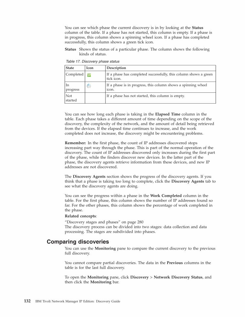
You can see which phase the current discovery is in by looking at the Statuscolumn of the table. If a phase has not started, this column is empty. If a phase isin progress, this column shows a spinning wheel icon. If a phase has completedsuccessfully, this column shows a green tick icon.
Status Shows the status of a particular phase. The column shows the followingkinds of status.
Table 17. Discovery phase status
State Icon Description
Completed If a phase has completed successfully, this column shows a greentick icon.
Inprogress
If a phase is in progress, this column shows a spinning wheelicon.
Notstarted
If a phase has not started, this column is empty.
You can see how long each phase is taking in the Elapsed Time column in thetable. Each phase takes a different amount of time depending on the scope of thediscovery, the complexity of the network, and the amount of detail being retrievedfrom the devices. If the elapsed time continues to increase, and the workcompleted does not increase, the discovery might be encountering problems.
Remember: In the first phase, the count of IP addresses discovered stopsincreasing part way through the phase. This is part of the normal operation of thediscovery. The count of IP addresses discovered only increases during the first partof the phase, while the finders discover new devices. In the latter part of thephase, the discovery agents retrieve information from these devices, and new IPaddresses are not discovered.
The Discovery Agents section shows the progress of the discovery agents. If youthink that a phase is taking too long to complete, click the Discovery Agents tab tosee what the discovery agents are doing.
You can see the progress within a phase in the Work Completed column in thetable. For the first phase, this column shows the number of IP addresses found sofar. For the other phases, this column shows the percentage of work completed inthe phase.Related concepts:“Discovery stages and phases” on page 280The discovery process can be divided into two stages: data collection and dataprocessing. The stages are subdivided into phases.
Comparing discoveriesYou can use the Monitoring pane to compare the current discovery to the previousfull discovery.
You cannot compare partial discoveries. The data in the Previous columns in thetable is for the last full discovery.
To open the Monitoring pane, click Discovery > Network Discovery Status, andthen click the Monitoring bar.
132 IBM Tivoli Network Manager IP Edition: Discovery Guide
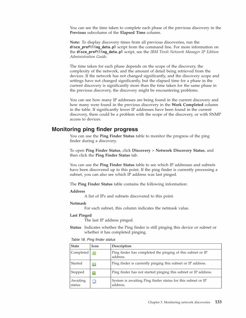
You can see the time taken to complete each phase of the previous discovery in thePrevious subcolumn of the Elapsed Time column.
Note: To display discovery times from all previous discoveries, run thedisco_profiling_data.pl script from the command line. For more information onthe disco_profiling_data.pl script, see the IBM Tivoli Network Manager IP EditionAdministration Guide.
The time taken for each phase depends on the scope of the discovery, thecomplexity of the network, and the amount of detail being retrieved from thedevices. If the network has not changed significantly, and the discovery scope andsettings have not changed significantly, but the elapsed time for a phase in thecurrent discovery is significantly more than the time taken for the same phase inthe previous discovery, the discovery might be encountering problems.
You can see how many IP addresses are being found in the current discovery andhow many were found in the previous discovery in the Work Completed columnin the table. If significantly fewer IP addresses have been found in the currentdiscovery, there could be a problem with the scope of the discovery, or with SNMPaccess to devices.
Monitoring ping finder progressYou can use the Ping Finder Status table to monitor the progress of the pingfinder during a discovery.
To open Ping Finder Status, click Discovery > Network Discovery Status, andthen click the Ping Finder Status tab.
You can use the Ping Finder Status table to see which IP addresses and subnetshave been discovered up to this point. If the ping finder is currently processing asubnet, you can also see which IP address was last pinged.
The Ping Finder Status table contains the following information:
AddressA list of IPs and subnets discovered to this point.
NetmaskFor each subnet, this column indicates the netmask value.
Last PingedThe last IP address pinged.
Status Indicates whether the Ping finder is still pinging this device or subnet orwhether it has completed pinging.
Table 18. Ping finder status
State Icon Description
Completed Ping finder has completed the pinging of this subnet or IPaddress.
Started Ping finder is currently pinging this subnet or IP address.
Stopped Ping finder has not started pinging this subnet or IP address.
Awaitingstatus
System is awaiting Ping finder status for this subnet or IPaddress.
Chapter 3. Monitoring network discoveries 133
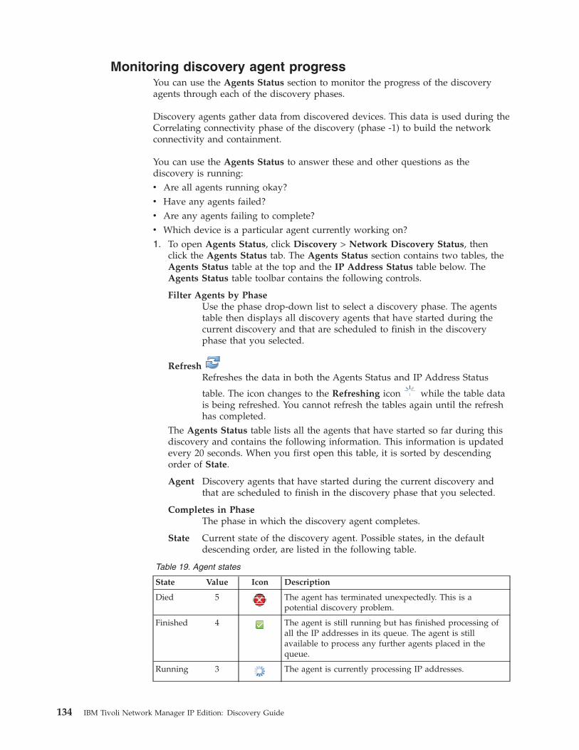
Monitoring discovery agent progressYou can use the Agents Status section to monitor the progress of the discoveryagents through each of the discovery phases.
Discovery agents gather data from discovered devices. This data is used during theCorrelating connectivity phase of the discovery (phase -1) to build the networkconnectivity and containment.
You can use the Agents Status to answer these and other questions as thediscovery is running:v Are all agents running okay?v Have any agents failed?v Are any agents failing to complete?v Which device is a particular agent currently working on?1. To open Agents Status, click Discovery > Network Discovery Status, then
click the Agents Status tab. The Agents Status section contains two tables, theAgents Status table at the top and the IP Address Status table below. TheAgents Status table toolbar contains the following controls.
Filter Agents by PhaseUse the phase drop-down list to select a discovery phase. The agentstable then displays all discovery agents that have started during thecurrent discovery and that are scheduled to finish in the discoveryphase that you selected.
RefreshRefreshes the data in both the Agents Status and IP Address Status
table. The icon changes to the Refreshing icon while the table datais being refreshed. You cannot refresh the tables again until the refreshhas completed.
The Agents Status table lists all the agents that have started so far during thisdiscovery and contains the following information. This information is updatedevery 20 seconds. When you first open this table, it is sorted by descendingorder of State.
Agent Discovery agents that have started during the current discovery andthat are scheduled to finish in the discovery phase that you selected.
Completes in PhaseThe phase in which the discovery agent completes.
State Current state of the discovery agent. Possible states, in the defaultdescending order, are listed in the following table.
Table 19. Agent states
State Value Icon Description
Died 5 The agent has terminated unexpectedly. This is apotential discovery problem.
Finished 4 The agent is still running but has finished processing ofall the IP addresses in its queue. The agent is stillavailable to process any further agents placed in thequeue.
Running 3 The agent is currently processing IP addresses.
134 IBM Tivoli Network Manager IP Edition: Discovery Guide
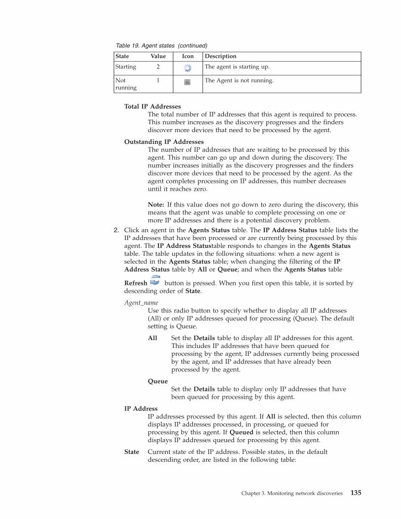
Table 19. Agent states (continued)
State Value Icon Description
Starting 2 The agent is starting up.
Notrunning
1 The Agent is not running.
Total IP AddressesThe total number of IP addresses that this agent is required to process.This number increases as the discovery progresses and the findersdiscover more devices that need to be processed by the agent.
Outstanding IP AddressesThe number of IP addresses that are waiting to be processed by thisagent. This number can go up and down during the discovery. Thenumber increases initially as the discovery progresses and the findersdiscover more devices that need to be processed by the agent. As theagent completes processing on IP addresses, this number decreasesuntil it reaches zero.
Note: If this value does not go down to zero during the discovery, thismeans that the agent was unable to complete processing on one ormore IP addresses and there is a potential discovery problem.
2. Click an agent in the Agents Status table. The IP Address Status table lists theIP addresses that have been processed or are currently being processed by thisagent. The IP Address Statustable responds to changes in the Agents Statustable. The table updates in the following situations: when a new agent isselected in the Agents Status table; when changing the filtering of the IPAddress Status table by All or Queue; and when the Agents Status table
Refresh button is pressed. When you first open this table, it is sorted bydescending order of State.
Agent_nameUse this radio button to specify whether to display all IP addresses(All) or only IP addresses queued for processing (Queue). The defaultsetting is Queue.
All Set the Details table to display all IP addresses for this agent.This includes IP addresses that have been queued forprocessing by the agent, IP addresses currently being processedby the agent, and IP addresses that have already beenprocessed by the agent.
QueueSet the Details table to display only IP addresses that havebeen queued for processing by this agent.
IP AddressIP addresses processed by this agent. If All is selected, then this columndisplays IP addresses processed, in processing, or queued forprocessing by this agent. If Queued is selected, then this columndisplays IP addresses queued for processing by this agent.
State Current state of the IP address. Possible states, in the defaultdescending order, are listed in the following table:
Chapter 3. Monitoring network discoveries 135
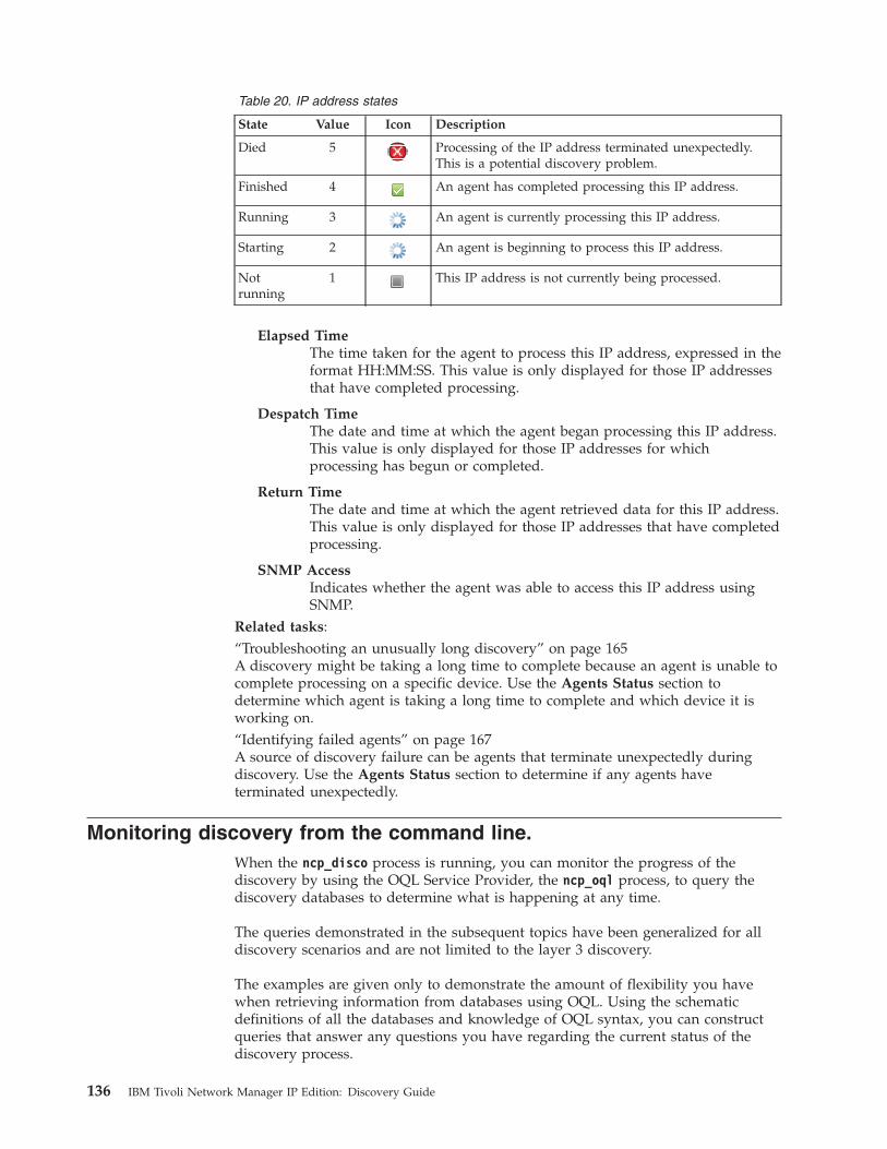
Table 20. IP address states
State Value Icon Description
Died 5 Processing of the IP address terminated unexpectedly.This is a potential discovery problem.
Finished 4 An agent has completed processing this IP address.
Running 3 An agent is currently processing this IP address.
Starting 2 An agent is beginning to process this IP address.
Notrunning
1 This IP address is not currently being processed.
Elapsed TimeThe time taken for the agent to process this IP address, expressed in theformat HH:MM:SS. This value is only displayed for those IP addressesthat have completed processing.
Despatch TimeThe date and time at which the agent began processing this IP address.This value is only displayed for those IP addresses for whichprocessing has begun or completed.
Return TimeThe date and time at which the agent retrieved data for this IP address.This value is only displayed for those IP addresses that have completedprocessing.
SNMP AccessIndicates whether the agent was able to access this IP address usingSNMP.
Related tasks:“Troubleshooting an unusually long discovery” on page 165A discovery might be taking a long time to complete because an agent is unable tocomplete processing on a specific device. Use the Agents Status section todetermine which agent is taking a long time to complete and which device it isworking on.“Identifying failed agents” on page 167A source of discovery failure can be agents that terminate unexpectedly duringdiscovery. Use the Agents Status section to determine if any agents haveterminated unexpectedly.
Monitoring discovery from the command line.When the ncp_disco process is running, you can monitor the progress of thediscovery by using the OQL Service Provider, the ncp_oql process, to query thediscovery databases to determine what is happening at any time.
The queries demonstrated in the subsequent topics have been generalized for alldiscovery scenarios and are not limited to the layer 3 discovery.
The examples are given only to demonstrate the amount of flexibility you havewhen retrieving information from databases using OQL. Using the schematicdefinitions of all the databases and knowledge of OQL syntax, you can constructqueries that answer any questions you have regarding the current status of thediscovery process.
136 IBM Tivoli Network Manager IP Edition: Discovery Guide

You can issue simple queries to find out, for example, what the ncp_disco processis currently doing, which discovery agents have discovered devices, or how manydevices have been discovered so far. You can also issue complex queries to findout, for example, which devices have been discovered by a specific discoveryagent, or which discovery agents have interrogated a specific device.
For information on starting the OQL Service Provider, including prerequisites, seethe IBM Tivoli Network Manager IP Edition Language Reference.Related tasks:“Discovering the network using the command-line interface” on page 47As an experienced user, you can configure and track a network discovery usingconfiguration files and database queries.
Sample discovery status queriesYou can use queries similar to these examples to find out the status of differentparts of the discovery.
Sample: Determining which address the Ping finder is pinging
The following query returns the current address being pinged by the Ping finder:select m_CurrentAddress from pingFinder.status;go.{
m_CurrentAddress=192.168.0.1;}
Sample: Identifying the current phase of the discovery
The following example shows how to identify the current phase of the discovery.The results of the above query show that the discovery process is still in datacollection phase 1.select * from disco.status;go.{
m_DiscoveryMode=0;m_Phase=1;m_BlackoutState=0;m_CycleCount=0;m_ProcessingNeeded=0;m_FullDiscovery=0;
}
Sample: Identifying the status of a NAT discovery
This example shows how to identify the status of the NAT discovery.select m_NATStatus from disco.NATStatus;go.{
m_NATStatus=3;}
Sample: Identifying which agents are enabled
This example shows how to identify whether you have enabled the appropriatediscovery agents.
Chapter 3. Monitoring network discoveries 137
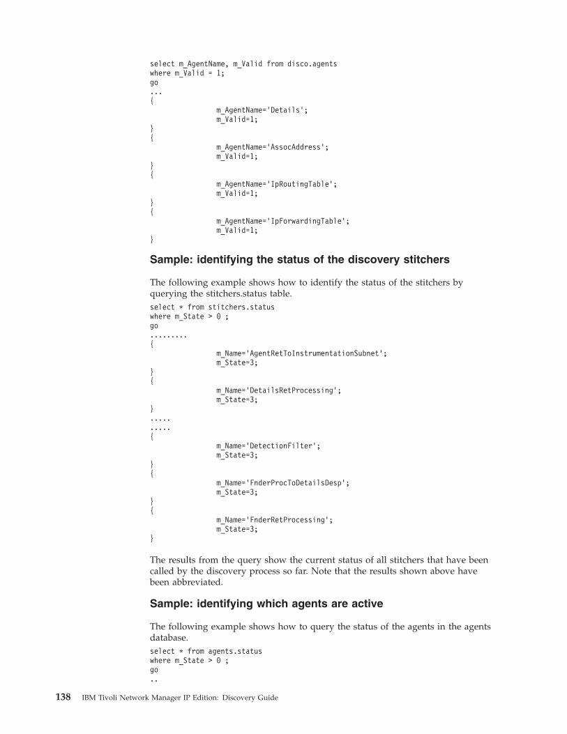
select m_AgentName, m_Valid from disco.agentswhere m_Valid = 1;go...{
m_AgentName=’Details’;m_Valid=1;
}{
m_AgentName=’AssocAddress’;m_Valid=1;
}{
m_AgentName=’IpRoutingTable’;m_Valid=1;
}{
m_AgentName=’IpForwardingTable’;m_Valid=1;
}
Sample: identifying the status of the discovery stitchers
The following example shows how to identify the status of the stitchers byquerying the stitchers.status table.select * from stitchers.statuswhere m_State > 0 ;go.........{
m_Name=’AgentRetToInstrumentationSubnet’;m_State=3;
}{
m_Name=’DetailsRetProcessing’;m_State=3;
}..........{
m_Name=’DetectionFilter’;m_State=3;
}{
m_Name=’FnderProcToDetailsDesp’;m_State=3;
}{
m_Name=’FnderRetProcessing’;m_State=3;
}
The results from the query show the current status of all stitchers that have beencalled by the discovery process so far. Note that the results shown above havebeen abbreviated.
Sample: identifying which agents are active
The following example shows how to query the status of the agents in the agentsdatabase.select * from agents.statuswhere m_State > 0 ;go..
138 IBM Tivoli Network Manager IP Edition: Discovery Guide
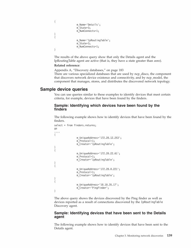
{m_Name=’Details’;m_State=3;m_NumConnects=1;
}{
m_Name=’IpRoutingTable’;m_State=3;m_NumConnects=1;
}
The results of the above query show that only the Details agent and theIpRoutingTable agent are active (that is, they have a state greater than zero).Related reference:Appendix A, “Discovery databases,” on page 183There are various specialized databases that are used by ncp_disco, the componentthat discovers network device existence and connectivity, and by ncp_model, thecomponent that manages, stores, and distributes the discovered network topology.
Sample device queriesYou can use queries similar to these examples to identify devices that meet certaincriteria, for example, devices that have been found by the finders.
Sample: Identifying which devices have been found by thefinders
The following example shows how to identify devices that have been found by thefinders.select * from finders.returns;go....{
m_UniqueAddress=’172.20.12.253’;m_Protocol=1;m_Creator=’IpRoutingTable’;
}{
m_UniqueAddress=’172.20.22.61’;m_Protocol=1;m_Creator=’IpRoutingTable’;
}{
m_UniqueAddress=’172.20.0.221’;m_Protocol=1;m_Creator=’IpRoutingTable’;
}{
m_UniqueAddress=’10.10.35.17’;m_Creator=’PingFinder’;
}
The above query shows the devices discovered by the Ping finder as well asdevices reported as a result of connections discovered by the IpRoutingTableDiscovery agent.
Sample: Identifying devices that have been sent to the Detailsagent
The following example shows how to identify devices that have been sent to theDetails agent.
Chapter 3. Monitoring network discoveries 139
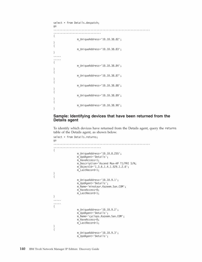
select * from Details.despatch;go.................................................................................................{
m_UniqueAddress=’10.10.38.82’;}{
m_UniqueAddress=’10.10.38.83’;}..........{
m_UniqueAddress=’10.10.38.84’;}{
m_UniqueAddress=’10.10.38.87’;}{
m_UniqueAddress=’10.10.38.88’;}{
m_UniqueAddress=’10.10.38.89’;}{
m_UniqueAddress=’10.10.38.90’;}
Sample: Identifying devices that have been returned from theDetails agent
To identify which devices have returned from the Details agent, query the returnstable of the Details agent, as shown below.select * from Details.returns;go.................................................................................................{
m_UniqueAddress=’10.10.8.255’;m_UpdAgent=’Details’;m_HaveAccess=1;m_Description=’Ascend Max-HP T1/PRI S/N;m_ObjectId=’1.3.6.1.4.1.529.1.2.6’;m_LastRecord=1;
}{
m_UniqueAddress=’10.10.9.1’;m_UpdAgent=’Details’;m_Name=’minotaur.Kazeem.San.COM’;m_HaveAccess=0;m_LastRecord=1;
}..........{
m_UniqueAddress=’10.10.9.2’;m_UpdAgent=’Details’;m_Name=’cyclops.Kazeem.San.COM’;m_HaveAccess=0;m_LastRecord=1;
}{
m_UniqueAddress=’10.10.9.3’;m_UpdAgent=’Details’;
140 IBM Tivoli Network Manager IP Edition: Discovery Guide
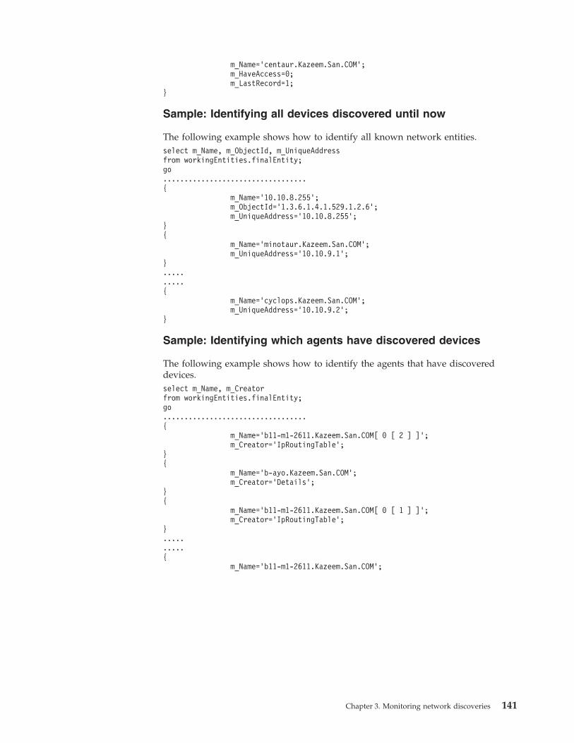
m_Name=’centaur.Kazeem.San.COM’;m_HaveAccess=0;m_LastRecord=1;
}
Sample: Identifying all devices discovered until now
The following example shows how to identify all known network entities.select m_Name, m_ObjectId, m_UniqueAddressfrom workingEntities.finalEntity;go..................................{
m_Name=’10.10.8.255’;m_ObjectId=’1.3.6.1.4.1.529.1.2.6’;m_UniqueAddress=’10.10.8.255’;
}{
m_Name=’minotaur.Kazeem.San.COM’;m_UniqueAddress=’10.10.9.1’;
}..........{
m_Name=’cyclops.Kazeem.San.COM’;m_UniqueAddress=’10.10.9.2’;
}
Sample: Identifying which agents have discovered devices
The following example shows how to identify the agents that have discovereddevices.select m_Name, m_Creatorfrom workingEntities.finalEntity;go..................................{
m_Name=’b11-m1-2611.Kazeem.San.COM[ 0 [ 2 ] ]’;m_Creator=’IpRoutingTable’;
}{
m_Name=’b-ayo.Kazeem.San.COM’;m_Creator=’Details’;
}{
m_Name=’b11-m1-2611.Kazeem.San.COM[ 0 [ 1 ] ]’;m_Creator=’IpRoutingTable’;
}..........{
m_Name=’b11-m1-2611.Kazeem.San.COM’;
Chapter 3. Monitoring network discoveries 141
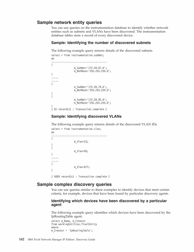
Sample network entity queriesYou can use queries on the instrumentation database to identify whether networkentities such as subnets and VLANs have been discovered. The instrumentationdatabase tables store a record of every discovered device.
Sample: Identifying the number of discovered subnets
The following example query returns details of the discovered subnets.select * from instrumentation.subNet;go.......................................{
m_SubNet=’172.20.67.0’;m_NetMask=’255.255.255.0’;
}..........{
m_SubNet=’172.20.70.0’;m_NetMask=’255.255.254.0’;
}{
m_SubNet=’172.20.95.0’;m_NetMask=’255.255.255.0’;
}( 81 record(s) : Transaction complete )
Sample: Identifying discovered VLANs
The following example query returns details of the discovered VLAN IDs.select * from instrumentation.vlan;go.......................................{
m_Vlan=23;}{
m_Vlan=65;}..........{
m_Vlan=677;}
( 4826 record(s) : Transaction complete )
Sample complex discovery queriesYou can use queries similar to these examples to identify devices that meet certaincriteria, for example, devices that have been found by particular discovery agents.
Identifying which devices have been discovered by a particularagent
The following example query identifies which devices have been discovered by theIpRoutingTable agent.select m_Name, m_Creatorfrom workingEntities.finalEntitywherem_Creator = ’IpRoutingTable’;
142 IBM Tivoli Network Manager IP Edition: Discovery Guide
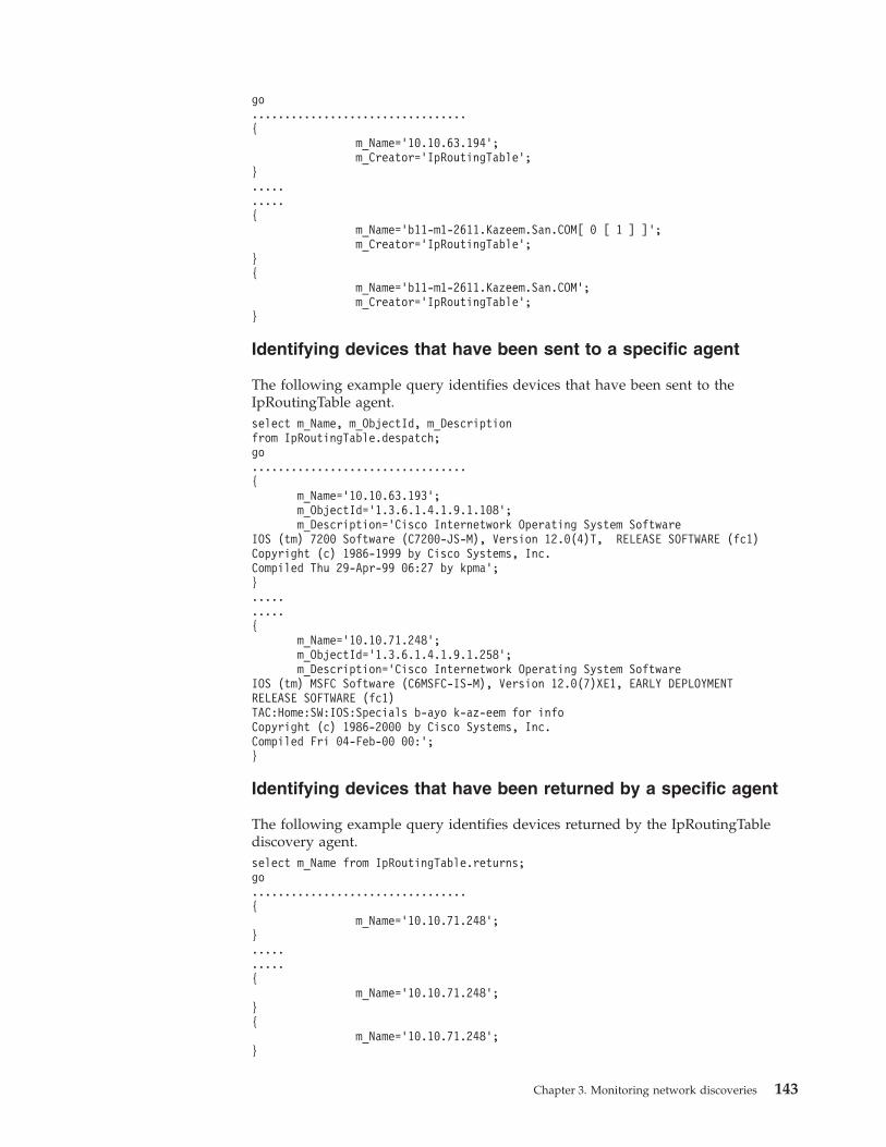
go.................................{
m_Name=’10.10.63.194’;m_Creator=’IpRoutingTable’;
}..........{
m_Name=’b11-m1-2611.Kazeem.San.COM[ 0 [ 1 ] ]’;m_Creator=’IpRoutingTable’;
}{
m_Name=’b11-m1-2611.Kazeem.San.COM’;m_Creator=’IpRoutingTable’;
}
Identifying devices that have been sent to a specific agent
The following example query identifies devices that have been sent to theIpRoutingTable agent.select m_Name, m_ObjectId, m_Descriptionfrom IpRoutingTable.despatch;go.................................{
m_Name=’10.10.63.193’;m_ObjectId=’1.3.6.1.4.1.9.1.108’;m_Description=’Cisco Internetwork Operating System Software
IOS (tm) 7200 Software (C7200-JS-M), Version 12.0(4)T, RELEASE SOFTWARE (fc1)Copyright (c) 1986-1999 by Cisco Systems, Inc.Compiled Thu 29-Apr-99 06:27 by kpma’;}..........{
m_Name=’10.10.71.248’;m_ObjectId=’1.3.6.1.4.1.9.1.258’;m_Description=’Cisco Internetwork Operating System Software
IOS (tm) MSFC Software (C6MSFC-IS-M), Version 12.0(7)XE1, EARLY DEPLOYMENTRELEASE SOFTWARE (fc1)TAC:Home:SW:IOS:Specials b-ayo k-az-eem for infoCopyright (c) 1986-2000 by Cisco Systems, Inc.Compiled Fri 04-Feb-00 00:’;}
Identifying devices that have been returned by a specific agent
The following example query identifies devices returned by the IpRoutingTablediscovery agent.select m_Name from IpRoutingTable.returns;go.................................{
m_Name=’10.10.71.248’;}..........{
m_Name=’10.10.71.248’;}{
m_Name=’10.10.71.248’;}
Chapter 3. Monitoring network discoveries 143
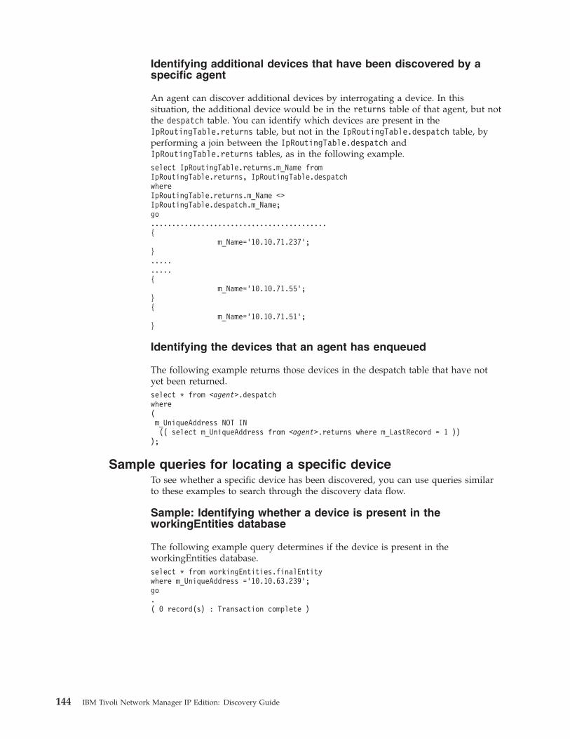
Identifying additional devices that have been discovered by aspecific agent
An agent can discover additional devices by interrogating a device. In thissituation, the additional device would be in the returns table of that agent, but notthe despatch table. You can identify which devices are present in theIpRoutingTable.returns table, but not in the IpRoutingTable.despatch table, byperforming a join between the IpRoutingTable.despatch andIpRoutingTable.returns tables, as in the following example.select IpRoutingTable.returns.m_Name fromIpRoutingTable.returns, IpRoutingTable.despatchwhereIpRoutingTable.returns.m_Name <>IpRoutingTable.despatch.m_Name;go..........................................{
m_Name=’10.10.71.237’;}..........{
m_Name=’10.10.71.55’;}{
m_Name=’10.10.71.51’;}
Identifying the devices that an agent has enqueued
The following example returns those devices in the despatch table that have notyet been returned.select * from <agent>.despatchwhere(m_UniqueAddress NOT IN(( select m_UniqueAddress from <agent>.returns where m_LastRecord = 1 ))
);
Sample queries for locating a specific deviceTo see whether a specific device has been discovered, you can use queries similarto these examples to search through the discovery data flow.
Sample: Identifying whether a device is present in theworkingEntities database
The following example query determines if the device is present in theworkingEntities database.select * from workingEntities.finalEntitywhere m_UniqueAddress =’10.10.63.239’;go.( 0 record(s) : Transaction complete )
144 IBM Tivoli Network Manager IP Edition: Discovery Guide

Sample: Identifying whether a device has been returned from theAssocAddress agent
If the device is not present in the workingEntities database, you can use thefollowing example query to determine if the device has been returned from theAssocAddress agent.select * from AssocAddress.returnswhere m_UniqueAddress = ’10.10.63.239’;go.( 0 record(s) : Transaction complete )
Sample: Identifying whether a device has been returned from theDetails agent
If the device has not been returned from the AssocAddress agent, you can use thefollowing example query to determine if the device has been returned from theDetails agent.select * from Details.returnswhere m_UniqueAddress = ’10.10.63.239’;go.( 0 record(s) : Transaction complete )
Sample: Identify whether a device has been sent to the Detailsagent
If the device has not been returned from the Details agent, you can check if thedevice has been sent to the Details agent by querying the Details.despatch table,as shown below. This result indicates that the device has been sent to the Detailsagent, but has not yet been processed.select * from Details.despatchwhere m_UniqueAddress=’10.10.63.239’;go.{
m_UniqueAddress=’10.10.63.239’;}( 1 record(s) : Transaction complete )
Sample: Identifying whether a device has been discovered by thefinders
If the device is not in the Details.despatch table, you can query the findersdatabase, as shown below. This result shows that the device has been discoveredby the finders.select * from finders.processingwhere m_UniqueAddress=’10.10.63.239’;go.{
m_UniqueAddress=’10.10.63.239’;}( 1 record(s) : Transaction complete )
select * from finders.returnswhere m_UniqueAddress=’10.10.63.239’;go.( 0 record(s) : Transaction complete )
Chapter 3. Monitoring network discoveries 145

146 IBM Tivoli Network Manager IP Edition: Discovery Guide
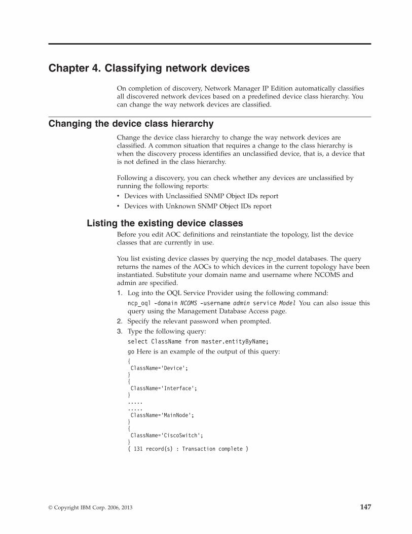
Chapter 4. Classifying network devices
On completion of discovery, Network Manager IP Edition automatically classifiesall discovered network devices based on a predefined device class hierarchy. Youcan change the way network devices are classified.
Changing the device class hierarchyChange the device class hierarchy to change the way network devices areclassified. A common situation that requires a change to the class hierarchy iswhen the discovery process identifies an unclassified device, that is, a device thatis not defined in the class hierarchy.
Following a discovery, you can check whether any devices are unclassified byrunning the following reports:v Devices with Unclassified SNMP Object IDs reportv Devices with Unknown SNMP Object IDs report
Listing the existing device classesBefore you edit AOC definitions and reinstantiate the topology, list the deviceclasses that are currently in use.
You list existing device classes by querying the ncp_model databases. The queryreturns the names of the AOCs to which devices in the current topology have beeninstantiated. Substitute your domain name and username where NCOMS andadmin are specified.1. Log into the OQL Service Provider using the following command:
ncp_oql -domain NCOMS -username admin service Model You can also issue thisquery using the Management Database Access page.
2. Specify the relevant password when prompted.3. Type the following query:
select ClassName from master.entityByName;
go Here is an example of the output of this query:{ClassName=’Device’;}{ClassName=’Interface’;}..........ClassName=’MainNode’;}{ClassName=’CiscoSwitch’;}( 131 record(s) : Transaction complete )
© Copyright IBM Corp. 2006, 2013 147

Creating and editing AOC filesCreate and edit AOC files to classify unclassified devices or to change the classhierarchy of your topology.
If the discovery process identified an unclassified device, you can classify thedevice by creating a new AOC file that is specific to the device class to which thisdevice belongs.
You can edit AOCs in either of two ways: update the ncp_class databases, ormodify the AOC file definitions:v If you want to update the ncp_class database (and therefore the current AOC
definitions) directly, then use the Management Database Access or the OQLService Provider.
v If you want to modify the AOC file definitions, then follow the steps in thistopic.
1. Go to the NCHOME/precision/aoc directory.2. Back up any files that you want to edit.3. Stop all running Network Manager processes.4. Create a new text file or edit an existing AOC file using a text editor.
Restriction: Only alphanumeric characters and the underscore (_) charactermay be used for AOC filenames. Any other characters, for example thehyphen (-) are forbidden.
5. If you created a new AOC file, add a new insert to the class.classIds databasetable in the ClassSchema.cfg configuration file.
6. Edit the startup options for the ncp_class process and set the -read_aocs_fromoption to ensure that the new or changed AOC files are read.
7. Start all Network Manager processes.8. Ensure that a domain-specific version of any new AOC files is present in the
NCHOME/precision/aoc directory.9. Back up and remove the discovery cache files in the NCHOME/var/precision
directory.10. Run a full discovery and check that the results match the changes you made.Related reference:“AOC specific to device class” on page 152Use this sample AOC file to understand how Network Manager assigns discovereddevices to the device class at a lower level in the class hierarchy.
Applying AOC changes to the topology and to the reportsAfter you have updated the AOC definitions and passed the changes to ncp_class,you can apply the changes to the topology by waiting for the next discovery tocomplete or by restarting the discovery at the point when the topology is passedfrom ncp_disco to ncp_model.
When the next full discovery completes, the AOC changes that you made areautomatically applied to the network topology.
If you do not want to wait for the next full discovery, use the appropriate stitcherto restart the discovery at the required point. To re-instantiate the containmentmodel, you must start the stitcher that sends the scratch topology from ncp_discoto ncp_model.
148 IBM Tivoli Network Manager IP Edition: Discovery Guide
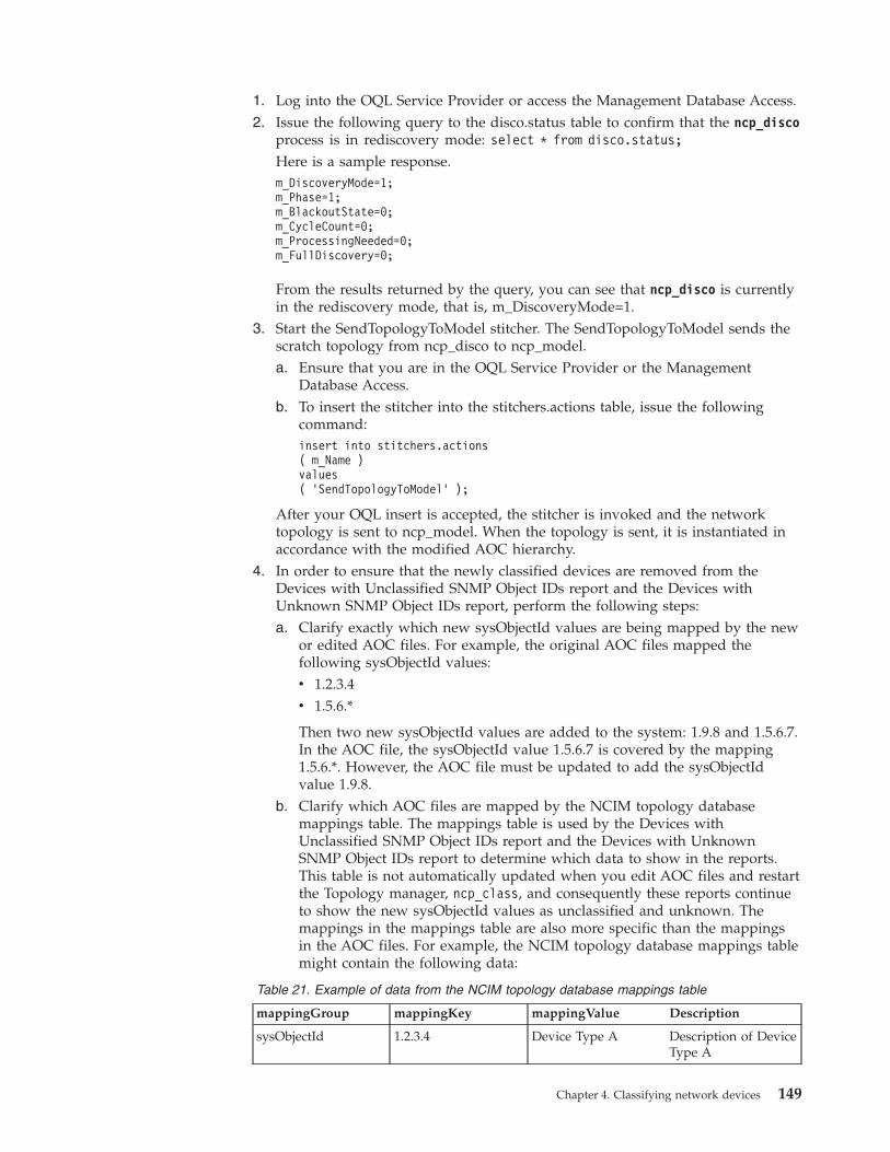
1. Log into the OQL Service Provider or access the Management Database Access.2. Issue the following query to the disco.status table to confirm that the ncp_disco
process is in rediscovery mode: select * from disco.status;
Here is a sample response.m_DiscoveryMode=1;m_Phase=1;m_BlackoutState=0;m_CycleCount=0;m_ProcessingNeeded=0;m_FullDiscovery=0;
From the results returned by the query, you can see that ncp_disco is currentlyin the rediscovery mode, that is, m_DiscoveryMode=1.
3. Start the SendTopologyToModel stitcher. The SendTopologyToModel sends thescratch topology from ncp_disco to ncp_model.a. Ensure that you are in the OQL Service Provider or the Management
Database Access.b. To insert the stitcher into the stitchers.actions table, issue the following
command:insert into stitchers.actions( m_Name )values( ’SendTopologyToModel’ );
After your OQL insert is accepted, the stitcher is invoked and the networktopology is sent to ncp_model. When the topology is sent, it is instantiated inaccordance with the modified AOC hierarchy.
4. In order to ensure that the newly classified devices are removed from theDevices with Unclassified SNMP Object IDs report and the Devices withUnknown SNMP Object IDs report, perform the following steps:a. Clarify exactly which new sysObjectId values are being mapped by the new
or edited AOC files. For example, the original AOC files mapped thefollowing sysObjectId values:v 1.2.3.4v 1.5.6.*
Then two new sysObjectId values are added to the system: 1.9.8 and 1.5.6.7.In the AOC file, the sysObjectId value 1.5.6.7 is covered by the mapping1.5.6.*. However, the AOC file must be updated to add the sysObjectIdvalue 1.9.8.
b. Clarify which AOC files are mapped by the NCIM topology databasemappings table. The mappings table is used by the Devices withUnclassified SNMP Object IDs report and the Devices with UnknownSNMP Object IDs report to determine which data to show in the reports.This table is not automatically updated when you edit AOC files and restartthe Topology manager, ncp_class, and consequently these reports continueto show the new sysObjectId values as unclassified and unknown. Themappings in the mappings table are also more specific than the mappingsin the AOC files. For example, the NCIM topology database mappings tablemight contain the following data:
Table 21. Example of data from the NCIM topology database mappings table
mappingGroup mappingKey mappingValue Description
sysObjectId 1.2.3.4 Device Type A Description of DeviceType A
Chapter 4. Classifying network devices 149
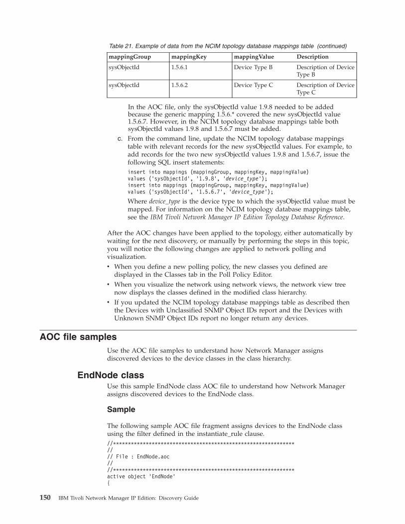
Table 21. Example of data from the NCIM topology database mappings table (continued)
mappingGroup mappingKey mappingValue Description
sysObjectId 1.5.6.1 Device Type B Description of DeviceType B
sysObjectId 1.5.6.2 Device Type C Description of DeviceType C
In the AOC file, only the sysObjectId value 1.9.8 needed to be addedbecause the generic mapping 1.5.6.* covered the new sysObjectId value1.5.6.7. However, in the NCIM topology database mappings table bothsysObjectId values 1.9.8 and 1.5.6.7 must be added.
c. From the command line, update the NCIM topology database mappingstable with relevant records for the new sysObjectId values. For example, toadd records for the two new sysObjectId values 1.9.8 and 1.5.6.7, issue thefollowing SQL insert statements:insert into mappings (mappingGroup, mappingKey, mappingValue)values (’sysObjectId’, ’1.9.8’, ’device_type’);insert into mappings (mappingGroup, mappingKey, mappingValue)values (’sysObjectId’, ’1.5.6.7’, ’device_type’);
Where device_type is the device type to which the sysObjectId value must bemapped. For information on the NCIM topology database mappings table,see the IBM Tivoli Network Manager IP Edition Topology Database Reference.
After the AOC changes have been applied to the topology, either automatically bywaiting for the next discovery, or manually by performing the steps in this topic,you will notice the following changes are applied to network polling andvisualization.v When you define a new polling policy, the new classes you defined are
displayed in the Classes tab in the Poll Policy Editor.v When you visualize the network using network views, the network view tree
now displays the classes defined in the modified class hierarchy.v If you updated the NCIM topology database mappings table as described then
the Devices with Unclassified SNMP Object IDs report and the Devices withUnknown SNMP Object IDs report no longer return any devices.
AOC file samplesUse the AOC file samples to understand how Network Manager assignsdiscovered devices to the device classes in the class hierarchy.
EndNode classUse this sample EndNode class AOC file to understand how Network Managerassigns discovered devices to the EndNode class.
Sample
The following sample AOC file fragment assigns devices to the EndNode classusing the filter defined in the instantiate_rule clause.//*************************************************************//// File : EndNode.aoc////*************************************************************active object ’EndNode’{
150 IBM Tivoli Network Manager IP Edition: Discovery Guide
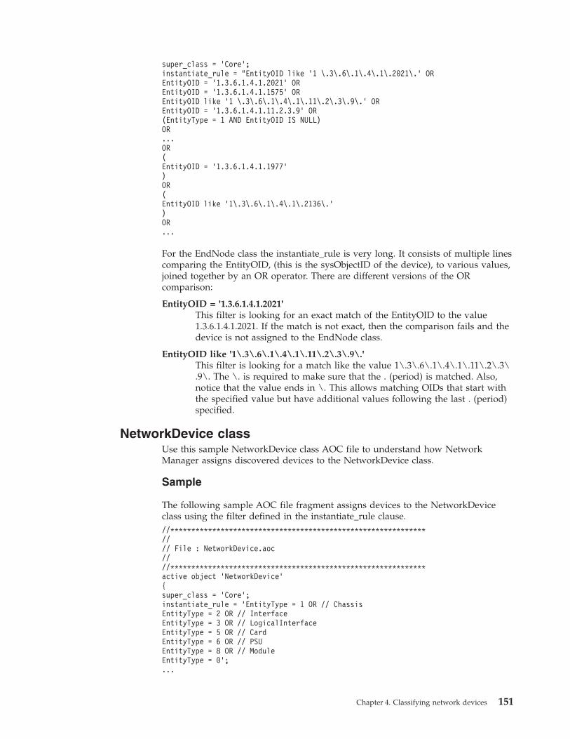
super_class = ’Core’;instantiate_rule = "EntityOID like ’1 \.3\.6\.1\.4\.1\.2021\.’ OREntityOID = ’1.3.6.1.4.1.2021’ OREntityOID = ’1.3.6.1.4.1.1575’ OREntityOID like ’1 \.3\.6\.1\.4\.1\.11\.2\.3\.9\.’ OREntityOID = ’1.3.6.1.4.1.11.2.3.9’ OR(EntityType = 1 AND EntityOID IS NULL)OR...OR(EntityOID = ’1.3.6.1.4.1.1977’)OR(EntityOID like ’1\.3\.6\.1\.4\.1\.2136\.’)OR...
For the EndNode class the instantiate_rule is very long. It consists of multiple linescomparing the EntityOID, (this is the sysObjectID of the device), to various values,joined together by an OR operator. There are different versions of the ORcomparison:
EntityOID = '1.3.6.1.4.1.2021'This filter is looking for an exact match of the EntityOID to the value1.3.6.1.4.1.2021. If the match is not exact, then the comparison fails and thedevice is not assigned to the EndNode class.
EntityOID like '1\.3\.6\.1\.4\.1\.11\.2\.3\.9\.'This filter is looking for a match like the value 1\.3\.6\.1\.4\.1\.11\.2\.3\.9\. The \. is required to make sure that the . (period) is matched. Also,notice that the value ends in \. This allows matching OIDs that start withthe specified value but have additional values following the last . (period)specified.
NetworkDevice classUse this sample NetworkDevice class AOC file to understand how NetworkManager assigns discovered devices to the NetworkDevice class.
Sample
The following sample AOC file fragment assigns devices to the NetworkDeviceclass using the filter defined in the instantiate_rule clause.//*************************************************************//// File : NetworkDevice.aoc////*************************************************************active object ’NetworkDevice’{super_class = ’Core’;instantiate_rule = ’EntityType = 1 OR // ChassisEntityType = 2 OR // InterfaceEntityType = 3 OR // LogicalInterfaceEntityType = 5 OR // CardEntityType = 6 OR // PSUEntityType = 8 OR // ModuleEntityType = 0’;...
Chapter 4. Classifying network devices 151
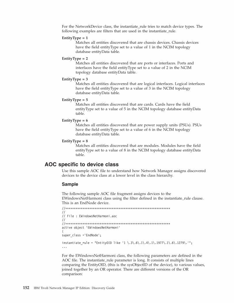
For the NetworkDevice class, the instantiate_rule tries to match device types. Thefollowing examples are filters that are used in the instantiate_rule.
EntityType = 1Matches all entities discovered that are chassis devices. Chassis deviceshave the field entityType set to a value of 1 in the NCIM topologydatabase entityData table.
EntityType = 2Matches all entities discovered that are ports or interfaces. Ports andinterfaces have the field entityType set to a value of 2 in the NCIMtopology database entityData table.
EntityType = 3Matches all entities discovered that are logical interfaces. Logical interfaceshave the field entityType set to a value of 3 in the NCIM topologydatabase entityData table.
EntityType = 5Matches all entities discovered that are cards. Cards have the fieldentityType set to a value of 5 in the NCIM topology database entityDatatable.
EntityType = 6Matches all entities discovered that are power supply units (PSUs). PSUshave the field entityType set to a value of 6 in the NCIM topologydatabase entityData table.
EntityType = 8Matches all entities discovered that are modules. Modules have the fieldentityType set to a value of 8 in the NCIM topology database entityDatatable.
AOC specific to device classUse this sample AOC file to understand how Network Manager assigns discovereddevices to the device class at a lower level in the class hierarchy.
Sample
The following sample AOC file fragment assigns devices to theEWindowsNetHarmoni class using the filter defined in the instantiate_rule clause.This is an EndNode device.//*************************************************************//// File : EWindowsNetHarmoni.aoc////*************************************************************active object ’EWindowsNetHarmoni’{super_class =’EndNode’;
instantiate_rule = "EntityOID like ’1 \.3\.6\.1\.4\.1\.1977\.1\.6\.1279\.’";...
For the EWindowsNetHarmoni class, the following parameters are defined in theAOC file. The instantiate_rule parameter is long. It consists of multiple linescomparing the EntityOID, (this is the sysObjectID of the device), to various values,joined together by an OR operator. There are different versions of the ORcomparison:
152 IBM Tivoli Network Manager IP Edition: Discovery Guide

super_class ='EndNode'This parameter establishes the device as belonging to the EndNode class.The EWindowsNetHarmoni class inherits all the attributes of the EndNodeclass.
instantiate_rule = "EntityOID like '1 \.3\.6\.1\.4\.1\.1977\.1\.6\.1279\.'"This filter is looking for a match to the value 1\.3\.6\.1\.4\.1\.11\.2\.3\.9\. The \. is required to make sure that the . (period) is matched. Also,notice that the value ends in \. This allows matching OIDs that start withthe specified value but have additional values following the last . (period)specified.
Chapter 4. Classifying network devices 153

154 IBM Tivoli Network Manager IP Edition: Discovery Guide
Chapter 5. Keeping discovered topology up-to-date
After a discovery has completed, you can keep the discovered topology updatedby scheduling a discovery, configuring automatic discovery, manually discoveringdevices, and removing devices.
Scheduling a discoveryAfter a full discovery has completed, you can schedule further discoveries byediting the FullDiscovery.stch file.
To schedule a discovery using the FullDiscovery.stch file:1. Back up and edit the NCHOME/disco/stitchers/FullDiscovery.stch file.2. Uncomment one of the ActOnTimedTrigger lines, and modify it to run the
discovery at a certain time. As an example, to schedule the discovery for 11:00PM every day, modify the line as follows:ActOnTimedTrigger(( m_TimeOfDay ) values ( 2300 ) ; );
3. Save and exit the file.
Here are several other examples of scheduling a discovery.v To schedule a discovery on the sixth day of the week since Sunday (Saturday) at
11 PM (where Sunday = 0, Monday = 1, Tuesday = 2, Wednesday = 3, Thursday= 4, Friday = 5, Saturday = 6):ActOnTimedTrigger(( m_DayOfWeek , m_TimeOfDay )values ( 6 , 2300 ) ; ) ;
v To schedule a discovery on the thirteenth day of each month at 2 PM:ActOnTimedTrigger(( m_DayOfMonth , m_TimeOfDay )values ( 13 , 1400 ) ; );
v To schedule a discovery at intervals of 13 hours:ActOnTimedTrigger(( m_Interval ) values ( 13 ) ; );
Related concepts:“About types of discovery” on page 1Different terms are used to describe network discovery, depending on what isbeing discovered and how the discovery has been configured. You can rundiscoveries, rediscoveries, full and partial discoveries, and you can set upautomatic discovery.
Configuring automatic discoveryNetwork Manager provides a mechanism to automatically trigger a partialdiscovery based on receipt of a trap. This is performed by the Disco plug-in to theEvent Gateway. Device traps might indicate a change in a network device or thepresence of a new network device.For more information on the Disco plug-in, seethe IBM Tivoli Network Manager IP Edition Event Management Guide.
© Copyright IBM Corp. 2006, 2013 155
Related concepts:“About types of discovery” on page 1Different terms are used to describe network discovery, depending on what isbeing discovered and how the discovery has been configured. You can rundiscoveries, rediscoveries, full and partial discoveries, and you can set upautomatic discovery.
Manually discovering a device or subnetYou can manually discover devices so that the network topology in NetworkManager matches the network.
Sometimes you might know that one or more devices have had their configurationchanged, and want to discover them again regardless of whether the system hasdetected the change from traps sent by the devices.
You can manually discover a device or subnet in the following ways:v You can use the Discovery Configuration GUI to specify individual devices or
complete subnets to be discovered.v You can discover specific devices or sets of devices from the Hop View or
Network Views.v You can make inserts to the finders.rediscovery table using ncp_oql, specifying
the IP address or subnet to be discovered.
Note: Do not use manual discoveries to remove devices from the topology. Devicesthat are no longer accessible remain in the topology until their LingerTime reacheszero and another discovery is run. Do manual discoveries only against devices thatare operational but whose configuration has been changed.Related tasks:“Removing a device from the network” on page 160You can manually remove a device that is known to be scheduled for permanentremoval from the network.“Monitoring network discovery from the GUI” on page 131From the Active Discovery Status page, you can monitor the status and progress ofthe current discovery, investigate the work of the discovery agents, and viewdetails of the last discovery.
Manually discovering a device or subnet using the GUIYou can configure and launch discovery of a device or subnet from the DiscoveryConfiguration GUI. You can customize the discovery configuration to make partialdiscovery run as quickly as possible.
Enabling partial discovery agentsYou can configure partial discovery by enabling the appropriate agents from thePartial Discovery Agents tab in the Discovery Configuration GUI.
You can speed up the time taken for a partial discovery by selecting only thoseagents essential to discover new or modified devices.Related reference:“Guidance for selecting agents” on page 336To discover device technologies (that is, those that use protocols other than IP) onyour network, you must ensure that the appropriate agents are active.
156 IBM Tivoli Network Manager IP Edition: Discovery Guide
Configuring advanced partial discovery settingsAmong the advanced partial discovery settings that you can configure arefeedback, rebuilding of layer, and remote neighbor parameters.
Configuring feedback settings:
You can specify feedback settings when configuring a partial discovery with theGUI.
Feedback is the mechanism by which data returned by agents is used to find otherdevices. Examples of feedback data include the IP address of remote neighbors, orthe subnet within which a local neighbor exists.
The feedback mechanism allows any new IP addresses to be fed back into thediscovery and thus increases the size of the discovered network. You need tobalance completeness of the discovered topology (feedback on) with greater speedof discovery (feedback off).
You can choose from the following options after selecting the Advanced tab withinthe Configuration option in the Discovery Configuration GUI:v No Feedback: Feedback is off for all discoveries. This option provides speed but
discovers only those devices specified to the finders, and hence provides anincomplete topology. However, this setting ensures that discoveries complete inthe quickest possible time.
v Feedback: Feedback is on for full discoveries and partial discoveries. This optionprovides a complete topology in all situations but takes the longest time.
v Feedback Only on Full: Feedback is on for full discoveries, ensuring a completetopology. For partial discoveries there is no feedback. This ensures that thepartial discovery runs in the quickest time possible. This is the default setting.
Configuring rebuilding of layer settings:
You can allow the rebuilding of the topology layers to display an accuratetopology when you configure a partial discovery.
To rebuild the topology layers following a partial discovery, select the EnableRediscovery Rebuild Layers setting on the Advanced tab within the Configurationoption in the Discovery Configuration GUI. If you specify that topology layersshould be rebuilt following partial discovery, the result is an accurate topologyshowing all connectivity. However, the process of adding new devices takes longer.Related concepts:“Option to rebuild topology layers” on page 301You can specify whether to rebuild the topology layers following a partialrediscovery. Using this option, you can increase the speed of partial rediscovery.
Chapter 5. Keeping discovered topology up-to-date 157

Enabling discovery of remote neighbors for partial discovery:
You can improve the accuracy of connections found during a partial discovery byenabling the discovery of remote neighbors.
By default, remote neighbor discovery is off. Enabling remote neighbor discoverymakes the discovery take longer.
With remote neighbour discovery on, Network Manager checks, during a partialdiscovery, whether any connections to remote neighbors have changed. (Remoteneighbors in this context are connected devices that were in scope of the last fulldiscovery but are out of scope of the current partial discovery.)
If the connections have changed, the connected devices are included in the partialdiscovery, resulting in a more accurate topology.
Restriction: If a connection between devices has changed, but the informationabout the connection is stored only on the device that is out of scope, then thechange is not registered and the connected devices are not included in the partialdiscovery. Enabling remote neighbor discovery increases the accuracy of thetopology, if it has changed, but does not ensure that all changes are discovered. Forthe most accurate topology, run a full discovery.
To enable remote neighbor discovery, select Enable Rediscovery of RelatedDevices on the Advanced tab within the Configuration option in the DiscoveryConfiguration GUI.
Starting partial discovery from the GUIStarting a partial discovery involves defining a seed and scopes.
If a full discovery has not been run since the last time that the discovery engine,ncp_disco, was started, you cannot start a partial discovery.
You can start a partial discovery of a device or subnet from the Active DiscoveryStatus window. You can also discover specific devices by right-clicking them fromwithin the Hop View and Network Views.
To start a partial discovery from the Active Discovery Status window, complete thefollowing tasks.1. Select the domain in which you want to run a discovery from the Domain
menu. You can start to type the name of the domain, and matching domainsare listed below the Domain field.
2. Click the downward-facing arrow next to the Start Discovery buttonand select Start Partial Discovery from the menu. The Partial Discoverywindow is displayed. Specify the IP addresses and subnets that contain thedevices to be discovered
3. Under Partial Discovery, select the required nodes and subnets.4. To add a new subnet or node, click New.
5. Complete the fields as follows and click OK:
RediscoverSelect one of the following options:
IP AddressType the required IP address.
158 IBM Tivoli Network Manager IP Edition: Discovery Guide
SubnetType the required subnet and specify the number of netmaskbits. The Netmask field is automatically updated.
6. To add new scope zones, click Scope.
Note: If you add a scope zone that is not included within the scope of the lastfull discovery, connections between devices in the new scope and the old scopemight not be accurate until the next full discovery. Enabling remote neighbordiscovery can help improve the accuracy of these connections.
7. To add a new discovery scope zone click New . To edit an existing scopezone, click the required entry in the list.
8. Complete the fields as follows and click OK:
Scope By:Select one of the following options:
SubnetType the required subnet and specify the number of netmaskbits. The Netmask field is automatically updated.
You can specify a subnet or an individual IP address usingthese fields.v For example, to specify a Class C subnet 10.30.2.0, type
10.30.2.0/24, where 10.30.2.0 is the subnet prefix, and 24 isthe subnet mask.
v To specify an individual device, type an IP address and asubnet mask of 32. For example, type 10.30.1.20/32.
WildcardUse an asterisk (*) as a wildcard.
For example, to specify a scope of all IP addresses that beginwith the 10.30.200. subnet prefix, type 10.30.200.*.
Restriction: Network Manager does not support the IPv4–mapped IPv6format and expects all IPv6 addresses to be in standard colon-separatedIPv6 format. For example, Network Manager does not support anIPv4–mapped IPv6 address such as ::ffff:192.0.2.128. Instead enterthis address as ::ffff:c000:280 (standard colon-separated IPv6format).
ProtocolSelect the required Internet protocol: IPv4 or IPv6.
ActionDefine the subnet range as an inclusion zone or exclusion zone. If thesubnet range is an inclusion zone that you intend to ping during thediscovery, click Add to Ping Seed List. Clicking this optionautomatically adds the devices in the scope zone as a discovery seeddevices.
Restriction: The Add to Ping Seed List option is not available for IPv6scope zones. This prevents ping sweeping of IPv6 subnets, which canpotentially contain billions of devices to be pinged. Ping sweeping ofIPv6 subnets can therefore result in a non-terminating discovery.
Chapter 5. Keeping discovered topology up-to-date 159
9. Click OK then click Go. When a partial discovery is running, the Start
Discovery button is toggled off .Related concepts:“About types of discovery” on page 1Different terms are used to describe network discovery, depending on what isbeing discovered and how the discovery has been configured. You can rundiscoveries, rediscoveries, full and partial discoveries, and you can set upautomatic discovery.Related tasks:“Starting a discovery” on page 43After you configure a discovery, you can start and, if necessary, stop the discovery.“Monitoring network discovery from the GUI” on page 131From the Active Discovery Status page, you can monitor the status and progress ofthe current discovery, investigate the work of the discovery agents, and viewdetails of the last discovery.
Manually discovering a device or subnet from the commandline
You can manually discover a device or subnet from the command line.
To manually discover a device or subnet from the command line, make inserts tothe finders.rediscovery table using ncp_oql, specifying the IP address or subnetto be discovered, as described in the following example.
Manual discovery
To manually discover the device with IP address 192.168.1.2, first start the OQLService Provider using the following command:ncp_oql -domain NCOMS -service Disco
Having logged into the OQL provider, run the following query (note that thecommand is entered on one line):insert into finders.rediscovery (m_Address, m_RequestType) values("192.168.1.2", 1);
When discovery of a device is forced like this, ncp_disco immediately passes it tothe Ping finder to confirm it exists, and, if it does, triggers the appropriate agentsto reanalyze it. If the connections from the device have changed, neighboringdevices might also be discovered.
Removing a device from the networkYou can manually remove a device that is known to be scheduled for permanentremoval from the network.1. Suspend polling against the device. This prevents any spurious alerts being
raised against the device by the monitoring system as the device is poweredoff.
2. Physically remove the device from the network.3. Immediately before the next full network discovery, set the linger time for the
record of the device in ncp_model to 0.
160 IBM Tivoli Network Manager IP Edition: Discovery Guide
Related tasks:“Manually discovering a device or subnet” on page 156You can manually discover devices so that the network topology in NetworkManager matches the network.
Setting the linger time for a deviceThe value of the LingerTime field indicates how many discoveries a device can failto be found in before it is assumed to have been removed from the network andits record is removed from the topology. Setting the LingerTime field to zeroensures that when the device is not found in the next discovery, its record isimmediately removed from the topology.
To set the LingerTime field to zero:1. Enter a command similar to the following to start the OQL Service Provider:
ncp_oql -domain NCOMS -service Model
2. Update the LingerTime field in the master.entityByName table for all entitiesthat represent the device. For example, if the device is calledcore-router.abcd.com, enter the following command, on one line:update master.entityByName set LingerTime = 0where EntityName like ’core-router.abcd.com’;
Manually updating device detailsUpdated device details are sometimes not detected by discovery.
Sometimes changes you make to a device, such as giving it a new name, are notdetected by a subsequent discovery. When this happens, you can use the RemoveNode tool to remove the device from the network topology, and then rediscoverthe device based on its new details.
To manually update a device, follow these steps:1. Run the RemoveNode.pl script against the device.2. Rediscover the device.
Chapter 5. Keeping discovered topology up-to-date 161

162 IBM Tivoli Network Manager IP Edition: Discovery Guide
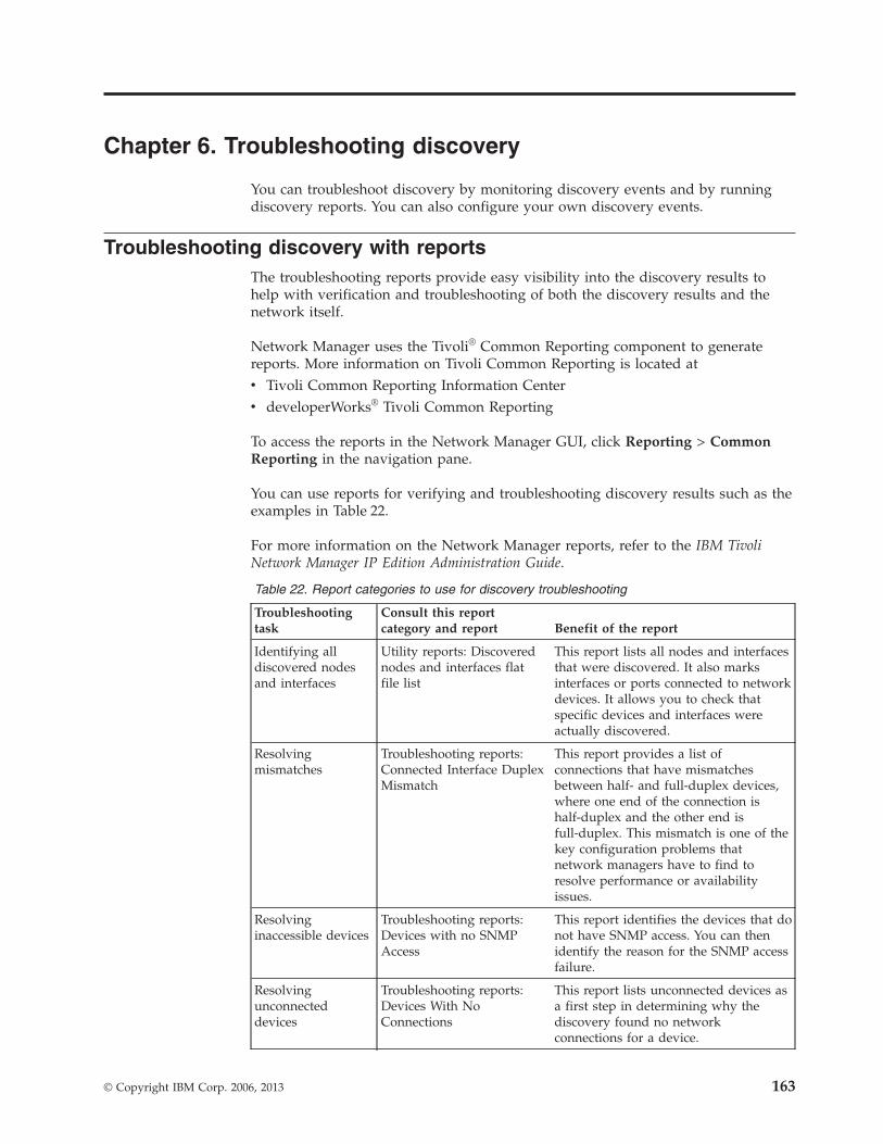
Chapter 6. Troubleshooting discovery
You can troubleshoot discovery by monitoring discovery events and by runningdiscovery reports. You can also configure your own discovery events.
Troubleshooting discovery with reportsThe troubleshooting reports provide easy visibility into the discovery results tohelp with verification and troubleshooting of both the discovery results and thenetwork itself.
Network Manager uses the Tivoli® Common Reporting component to generatereports. More information on Tivoli Common Reporting is located atv Tivoli Common Reporting Information Centerv developerWorks® Tivoli Common Reporting
To access the reports in the Network Manager GUI, click Reporting > CommonReporting in the navigation pane.
You can use reports for verifying and troubleshooting discovery results such as theexamples in Table 22.
For more information on the Network Manager reports, refer to the IBM TivoliNetwork Manager IP Edition Administration Guide.
Table 22. Report categories to use for discovery troubleshooting
Troubleshootingtask
Consult this reportcategory and report Benefit of the report
Identifying alldiscovered nodesand interfaces
Utility reports: Discoverednodes and interfaces flatfile list
This report lists all nodes and interfacesthat were discovered. It also marksinterfaces or ports connected to networkdevices. It allows you to check thatspecific devices and interfaces wereactually discovered.
Resolvingmismatches
Troubleshooting reports:Connected Interface DuplexMismatch
This report provides a list ofconnections that have mismatchesbetween half- and full-duplex devices,where one end of the connection ishalf-duplex and the other end isfull-duplex. This mismatch is one of thekey configuration problems thatnetwork managers have to find toresolve performance or availabilityissues.
Resolvinginaccessible devices
Troubleshooting reports:Devices with no SNMPAccess
This report identifies the devices that donot have SNMP access. You can thenidentify the reason for the SNMP accessfailure.
Resolvingunconnecteddevices
Troubleshooting reports:Devices With NoConnections
This report lists unconnected devices asa first step in determining why thediscovery found no networkconnections for a device.
© Copyright IBM Corp. 2006, 2013 163
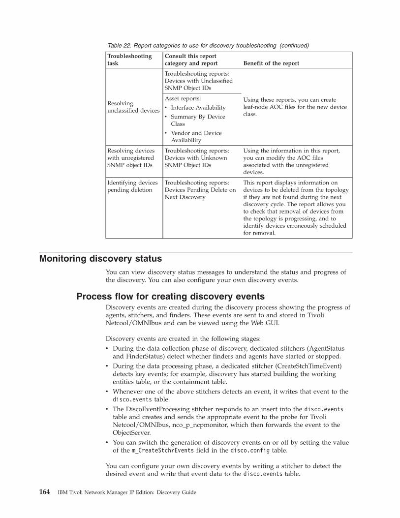
Table 22. Report categories to use for discovery troubleshooting (continued)
Troubleshootingtask
Consult this reportcategory and report Benefit of the report
Resolvingunclassified devices
Troubleshooting reports:Devices with UnclassifiedSNMP Object IDs
Using these reports, you can createleaf-node AOC files for the new deviceclass.
Asset reports:
v Interface Availability
v Summary By DeviceClass
v Vendor and DeviceAvailability
Resolving deviceswith unregisteredSNMP object IDs
Troubleshooting reports:Devices with UnknownSNMP Object IDs
Using the information in this report,you can modify the AOC filesassociated with the unregistereddevices.
Identifying devicespending deletion
Troubleshooting reports:Devices Pending Delete onNext Discovery
This report displays information ondevices to be deleted from the topologyif they are not found during the nextdiscovery cycle. The report allows youto check that removal of devices fromthe topology is progressing, and toidentify devices erroneously scheduledfor removal.
Monitoring discovery statusYou can view discovery status messages to understand the status and progress ofthe discovery. You can also configure your own discovery events.
Process flow for creating discovery eventsDiscovery events are created during the discovery process showing the progress ofagents, stitchers, and finders. These events are sent to and stored in TivoliNetcool/OMNIbus and can be viewed using the Web GUI.
Discovery events are created in the following stages:v During the data collection phase of discovery, dedicated stitchers (AgentStatus
and FinderStatus) detect whether finders and agents have started or stopped.v During the data processing phase, a dedicated stitcher (CreateStchTimeEvent)
detects key events; for example, discovery has started building the workingentities table, or the containment table.
v Whenever one of the above stitchers detects an event, it writes that event to thedisco.events table.
v The DiscoEventProcessing stitcher responds to an insert into the disco.eventstable and creates and sends the appropriate event to the probe for TivoliNetcool/OMNIbus, nco_p_ncpmonitor, which then forwards the event to theObjectServer.
v You can switch the generation of discovery events on or off by setting the valueof the m_CreateStchrEvents field in the disco.config table.
You can configure your own discovery events by writing a stitcher to detect thedesired event and write that event data to the disco.events table.
164 IBM Tivoli Network Manager IP Edition: Discovery Guide
Related reference:“disco.events table” on page 197The events table constrains discovery events generated to a standard format. Anevent is generated by inserting a record into this table.“Main discovery stitchers” on page 341This topic lists all discovery stitchers.
Monitoring discovery status messagesYou can view discovery status messages to understand the status and progress ofthe discovery.
The discovery processes, including agents, stitchers, and finders, send messages toIBM Tivoli Netcool/OMNIbus when they start and stop. You can view thesemessages to see if the discovery processes are running as expected, and to gaugethe overall progress of discovery.
To view discovery process status messages, complete the following tasks.1. Click Availability > Events > Active Event List (AEL) to view the Active
Event List (AEL).2. Apply a filter to the AEL so that only events with an Agent of ncp_disco are
displayed.3. Optional: Refine the filter or sort on EventId to view only specific kinds of
discovery events.4. Ensure that the LocalPriObj and LocalSecObj columns are displayed in the
AEL. These columns contain information for discovery events. (Not all columnsare used by all events.)
Troubleshooting discovery agentsYou can use the Discovery Status GUI to troubleshoot discovery problemsassociated with discovery agents.
Troubleshooting an unusually long discoveryA discovery might be taking a long time to complete because an agent is unable tocomplete processing on a specific device. Use the Agents Status section todetermine which agent is taking a long time to complete and which device it isworking on.
To use the Agents Status section to determine if the cause of the problem is anagent that is blocked on a device, complete the following steps:1. Open the Agents Status section by clicking Discovery > Network Discovery
Status, and then clicking the Agents Status tab.2. Set the Phases drop-down list above the upper Agents table to Interrogating
Devices. The upper Agents table now displays only agents that are scheduledto complete in the first discovery phase, Interrogating Devices.
Note: This problem usually occurs during the first discovery phase,Interrogating Devices.
3. Ensure that the State column is sorted in descending order. The agents appearby default in descending order of agent state, as listed in the following table.
Chapter 6. Troubleshooting discovery 165
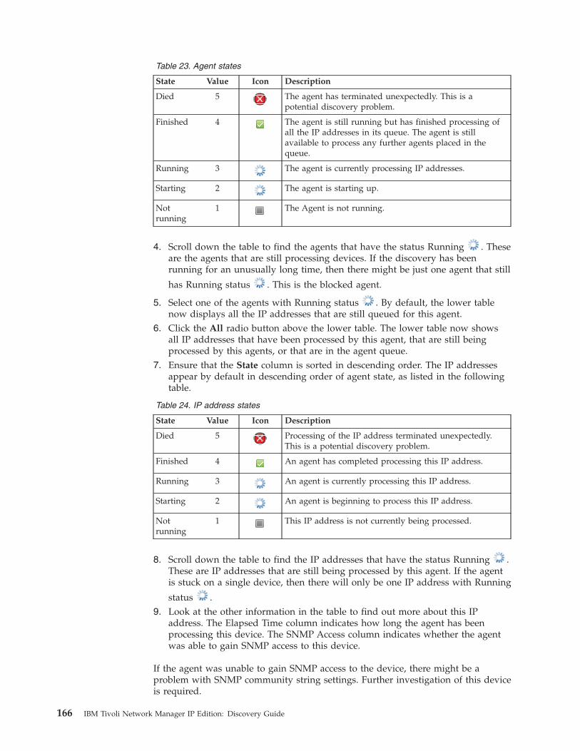
Table 23. Agent states
State Value Icon Description
Died 5 The agent has terminated unexpectedly. This is apotential discovery problem.
Finished 4 The agent is still running but has finished processing ofall the IP addresses in its queue. The agent is stillavailable to process any further agents placed in thequeue.
Running 3 The agent is currently processing IP addresses.
Starting 2 The agent is starting up.
Notrunning
1 The Agent is not running.
4. Scroll down the table to find the agents that have the status Running . Theseare the agents that are still processing devices. If the discovery has beenrunning for an unusually long time, then there might be just one agent that still
has Running status . This is the blocked agent.
5. Select one of the agents with Running status . By default, the lower tablenow displays all the IP addresses that are still queued for this agent.
6. Click the All radio button above the lower table. The lower table now showsall IP addresses that have been processed by this agent, that are still beingprocessed by this agents, or that are in the agent queue.
7. Ensure that the State column is sorted in descending order. The IP addressesappear by default in descending order of agent state, as listed in the followingtable.
Table 24. IP address states
State Value Icon Description
Died 5 Processing of the IP address terminated unexpectedly.This is a potential discovery problem.
Finished 4 An agent has completed processing this IP address.
Running 3 An agent is currently processing this IP address.
Starting 2 An agent is beginning to process this IP address.
Notrunning
1 This IP address is not currently being processed.
8. Scroll down the table to find the IP addresses that have the status Running .These are IP addresses that are still being processed by this agent. If the agentis stuck on a single device, then there will only be one IP address with Running
status .9. Look at the other information in the table to find out more about this IP
address. The Elapsed Time column indicates how long the agent has beenprocessing this device. The SNMP Access column indicates whether the agentwas able to gain SNMP access to this device.
If the agent was unable to gain SNMP access to the device, there might be aproblem with SNMP community string settings. Further investigation of this deviceis required.
166 IBM Tivoli Network Manager IP Edition: Discovery Guide
Related tasks:“Monitoring discovery agent progress” on page 134You can use the Agents Status section to monitor the progress of the discoveryagents through each of the discovery phases.
Identifying failed agentsA source of discovery failure can be agents that terminate unexpectedly duringdiscovery. Use the Agents Status section to determine if any agents haveterminated unexpectedly.
To use the Agents Status section to determine if any discovery agents are notrunning correctly, complete the following steps:1. Open the Agents Status section by clicking Discovery > Network Discovery
Status, and then clicking the Agents Status tab.2. Ensure that the Phases drop-down list above the upper Agents table is set to
All Phases. The upper Agents table now displays all agents that have started sofar in this discovery.
3. Click the State column in the upper Agents table so that the agents are orderedin descending order of State. The agents now appear in the table inalphabetical order of status.
4. Any agents that have terminated unexpectedly will be at the top of the tableand will have the status Died.
Further investigation is required to determine why this agent terminatedunexpectedly.Related tasks:“Monitoring discovery agent progress” on page 134You can use the Agents Status section to monitor the progress of the discoveryagents through each of the discovery phases.
Troubleshooting missing devicesIf a device that you expect to find in your network topology is not present, followthese steps to troubleshoot the problem.
Before following these steps, run a full discovery with feedback enabled.
To check some common causes for a device not being found in the network maps,complete the following steps.1. Verify that the device you're looking for is running and connected to the
network.2. Search for the device.
a. Search for the device in the network maps by hostname and then by IPaddress.
b. If you know which devices it is connected to, try finding one of theconnected devices in the Network Hop View. Then set the number of hopsto 1 and see if the device is shown as connected.
3. Check whether the device is in scope. Review the discovery scope, includingexclusion zones, in the Scope tab of the Network Discovery Configuration GUI.
4. Check if the device is being filtered out of the discovery.a. Click Filters.
Chapter 6. Troubleshooting discovery 167
b. Review the prediscovery and postdiscovery filters to ensure that the deviceis not being prevented from being discovered or instantiated.
Related tasks:“Setting discovery filters” on page 28Use filters to filter out devices either before discovery or after discovery. You canfilter out devices based on a variety of criteria, including location, technology, andmanufacturer. Filters provide additional restrictions to those defined in the scopezones.“Scoping discovery” on page 17To scope the discovery, define the zones of the network (that is, subnet ranges) thatyou want to include in the discovery, and the zones that you want to exclude.
Troubleshooting an idle discoveryIf you start the discovery, and after some minutes no devices have beendiscovered, follow these troubleshooting steps.
If the discovery status stays in phase zero (idle) after you start it, and no deviceshave been discovered, try the following troubleshooting steps.1. If you are using the file finder, check that you have correctly specified which
field in the seed file contains the IP address and which contains the host name.You can verify these settings in the Discovery Configuration GUI.
2. If you are using the ping finder and pinging individual IP addresses, check thatthese IP addresses are reachable. If not, you might have a network outage or afirewall issue.
3. Verify that the seed IP addresses are in scope. Even if you add an address tothe ping finder or file finder, the device is not pinged or instantiated if it is notincluded in the scope. For example, if your discovery scope is 172.16.1.0 /24and your seeds are in the 192.168.1.0 /24 network, then the finders cannot findthem.
4. If you are pinging a large, sparsely populated subnet, for example, a class Bsubnet containing only 10 devices, the ping finder might take a long time tofind the first device.
If you need to review the discovery logs, refer to the information about locatinglog files and changing logging levels in the IBM Tivoli Network Manager IP EditionAdministration Guide.Related tasks:“Starting a discovery” on page 43After you configure a discovery, you can start and, if necessary, stop the discovery.
Removing discovery cache filesRemove discovery cache files to perform a new, clean discovery.
To remove the current network discovery for a domain, you must remove alldiscovery cache files. You might want to do this when you need to remove all datafrom a previous discovery, or when directed to do so by IBM Support.
This procedure deletes all current discovery cache files and clears the discoverydatabase, effectively resetting discovery. After performing this procedure, you mustrun a new full discovery of your network.
168 IBM Tivoli Network Manager IP Edition: Discovery Guide
Note: Because the network topology is stored separately in the NCIM database,this procedure does not remove your network maps. However, any changes madeto your network since the last discovery are reflected in the next discovery.
Perform the following procedure to remove all discovery cache files:1. Stop all Network Manager processes using the itnm_stop script.2. Navigate to the $NCHOME/var/precision directory and remove all files that
belong to the domain you wish to remove. Files that belong to a particulardomain have the domain in the file name. For example, a configuration filebelonging to the domain NCOMS would be called file_name.NCOMS.cfg.
3. Optional: You can archive or remove existing log files and start the newdiscovery with fresh log files. The log files for the following processes arerelevant:v ncp_disco
v ncp_df_*v ncp_agent*v ncp_disco_perl_agent*
4. Restart the Network Manager processes using the itnm_start script.New, empty log files are automatically created when the Network Managerprocesses are restarted using the itnm_start scripts.
5. Perform a new network discovery.
Troubleshooting illegal characters in the Informix databaseIf you see an error message about illegal characters in insert statements into theInformix database, follow these steps to troubleshoot the problem.
If you have network devices with characters in their descriptions that are notallowed in the locale set in the Informix database, you might see an error messagesimilar to the following:Warning: W-RIV-002-206: [4115626896t] CMdlDbEntityMgr.cc(647)A database ’execute’ operation has failed :SQLRETURN = -1 CNcpODBCSth.cc line 233 : [Informix][Informix ODBC Driver][Informix]An illegal character has been found in the statement.
1. Back up and edit the SnmpStackSchema.cfg file.2. Locate the line that configures an insert into the snmpStack.conversionCfg table
and edit it to the following:insert into snmpStack.conversionCfg values (1);
3. Save and close the file.
The SNMP Helper substitutes characters returned from devices that are notallowed in the Informix database locale with the question mark character: '?'.
The SNMP Helper substitutes characters on only those objects that are configuredin the snmpStack.multibyteObjects table.
Chapter 6. Troubleshooting discovery 169

170 IBM Tivoli Network Manager IP Edition: Discovery Guide
Chapter 7. Enriching the topology
You can enrich the topology by adding extra context to the information discoveredby the discovery process. For example, you can add custom tags to devices toshow the customer, location, or other information associated with that device. Youcan then use this custom information to visualize or poll your network.
This section presents different examples of topology enrichment. Use theseexamples for an idea of the different ways in which the topology can be enrichedand the different methods available to enrich your topology.
Adding tags to entitiesYou can associate one or more name-value pair tags with discovered entities.
The following table shows an example of a device with IP address 172.20.3.20, withtwo associated name-value pair tags.
Table 25. Example of name-value pair tags
IP Address Name Value
172.20.3.20 customer acme
172.20.3.20 location london
Once the discovery has tagged your IP addresses with custom name-value pairtags, you can use the custom name-value pair information to perform customvisualization and polling tasks. For example, you could create a custom networkview to display all IP addresses that are tagged with the location "london".
Customizing the discoveryUse one of the following ways to customize the discovery to add name-value pairtags to discovered entities: using the file finder, or using custom tag tables. If youuse the custom tag tables then you can also use logic defined in the GetCustomTagstitcher to evaluate the value of the add name-value pair tag.
Adding tags to entities using the File finderIf you are using the File finder to seed your discovery, then you can addname-value pair tags to entities by adding extra columns to the seed file read bythe File finder.
The example procedure below assumes that you are adding the following extracolumns to your File finder seed file:v customerv location
The following example text file fragment shows what the seed file might look like:vi /var/tmp/logged_hosts
172.16.1.21 lnd-dharma-acme acme london172.16.1.201 lnd-phoenix-acme acme london172.16.1.25 prs-sun-acme acme paris172.16.2.33 ranger1 telecorp newyork
© Copyright IBM Corp. 2006, 2013 171
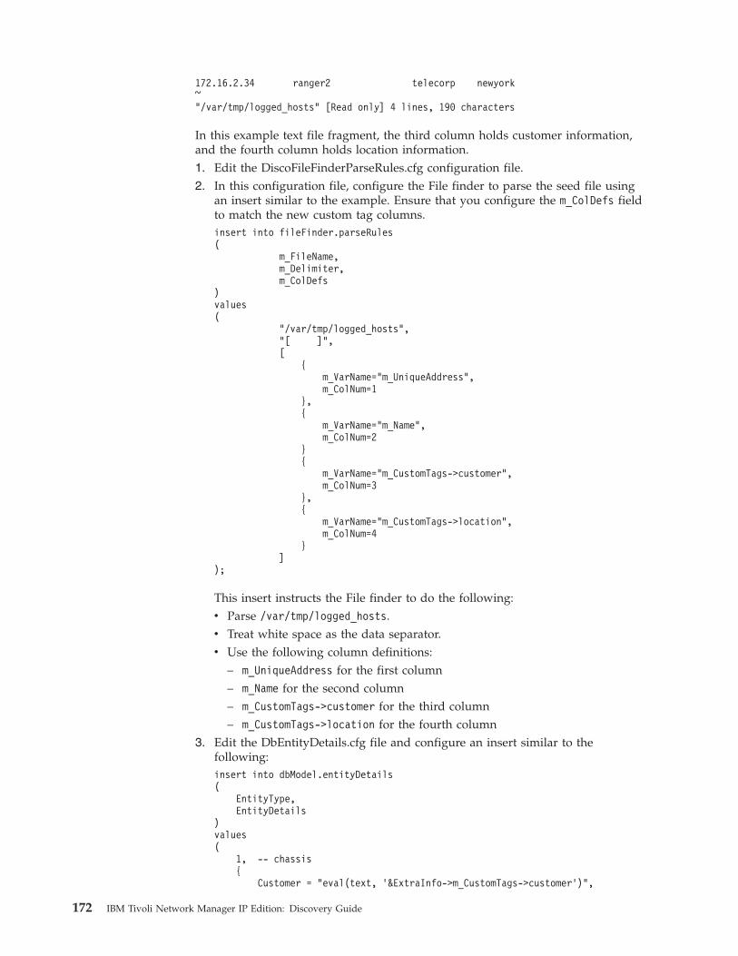
172.16.2.34 ranger2 telecorp newyork~"/var/tmp/logged_hosts" [Read only] 4 lines, 190 characters
In this example text file fragment, the third column holds customer information,and the fourth column holds location information.1. Edit the DiscoFileFinderParseRules.cfg configuration file.2. In this configuration file, configure the File finder to parse the seed file using
an insert similar to the example. Ensure that you configure the m_ColDefs fieldto match the new custom tag columns.insert into fileFinder.parseRules(
m_FileName,m_Delimiter,m_ColDefs
)values(
"/var/tmp/logged_hosts","[ ]",[
{m_VarName="m_UniqueAddress",m_ColNum=1
},{
m_VarName="m_Name",m_ColNum=2
}{
m_VarName="m_CustomTags->customer",m_ColNum=3
},{
m_VarName="m_CustomTags->location",m_ColNum=4
}]
);
This insert instructs the File finder to do the following:v Parse /var/tmp/logged_hosts.v Treat white space as the data separator.v Use the following column definitions:
– m_UniqueAddress for the first column– m_Name for the second column– m_CustomTags->customer for the third column– m_CustomTags->location for the fourth column
3. Edit the DbEntityDetails.cfg file and configure an insert similar to thefollowing:insert into dbModel.entityDetails(
EntityType,EntityDetails
)values(
1, -- chassis{
Customer = "eval(text, ’&ExtraInfo->m_CustomTags->customer’)",
172 IBM Tivoli Network Manager IP Edition: Discovery Guide
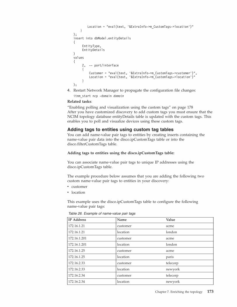
Location = "eval(text, ’&ExtraInfo->m_CustomTags->location’)"}
);insert into dbModel.entityDetails(
EntityType,EntityDetails
)values(
2, -- port/interface{
Customer = "eval(text, ’&ExtraInfo->m_CustomTags->customer’)",Location = "eval(text, ’&ExtraInfo->m_CustomTags->location’)"
});
4. Restart Network Manager to propagate the configuration file changes:itnm_start ncp -domain domain
Related tasks:“Enabling polling and visualization using the custom tags” on page 178After you have customized discovery to add custom tags you must ensure that theNCIM topology database entityDetails table is updated with the custom tags. Thisenables you to poll and visualize devices using these custom tags.
Adding tags to entities using custom tag tablesYou can add name-value pair tags to entities by creating inserts containing thename-value pair data into the disco.ipCustomTags table or into thedisco.filterCustomTags table.
Adding tags to entities using the disco.ipCustomTags table:
You can associate name-value pair tags to unique IP addresses using thedisco.ipCustomTags table.
The example procedure below assumes that you are adding the following twocustom name-value pair tags to entities in your discovery:v customerv location
This example uses the disco.ipCustomTags table to configure the followingname-value pair tags:
Table 26. Example of name-value pair tags
IP Address Name Value
172.16.1.21 customer acme
172.16.1.21 location london
172.16.1.201 customer acme
172.16.1.201 location london
172.16.1.25 customer acme
172.16.1.25 location paris
172.16.2.33 customer telecorp
172.16.2.33 location newyork
172.16.2.34 customer telecorp
172.16.2.34 location newyork
Chapter 7. Enriching the topology 173
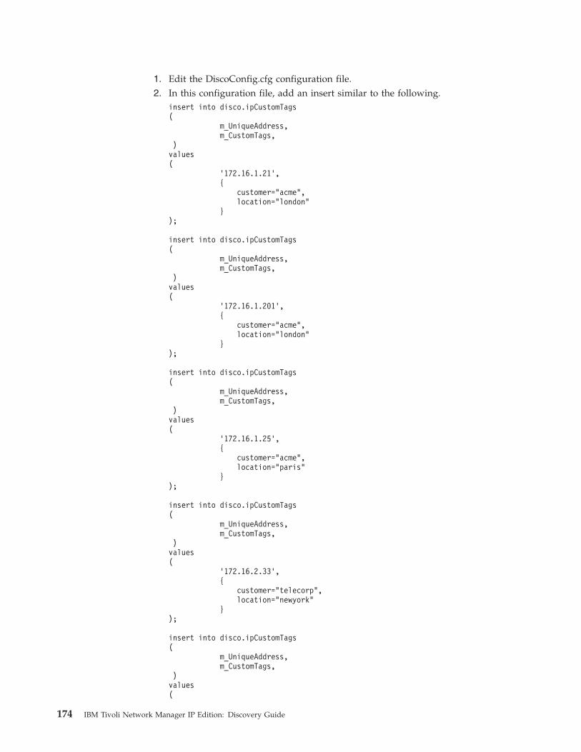
1. Edit the DiscoConfig.cfg configuration file.2. In this configuration file, add an insert similar to the following.
insert into disco.ipCustomTags(
m_UniqueAddress,m_CustomTags,
)values(
’172.16.1.21’,{
customer="acme",location="london"
});
insert into disco.ipCustomTags(
m_UniqueAddress,m_CustomTags,
)values(
’172.16.1.201’,{
customer="acme",location="london"
});
insert into disco.ipCustomTags(
m_UniqueAddress,m_CustomTags,
)values(
’172.16.1.25’,{
customer="acme",location="paris"
});
insert into disco.ipCustomTags(
m_UniqueAddress,m_CustomTags,
)values(
’172.16.2.33’,{
customer="telecorp",location="newyork"
});
insert into disco.ipCustomTags(
m_UniqueAddress,m_CustomTags,
)values(
174 IBM Tivoli Network Manager IP Edition: Discovery Guide
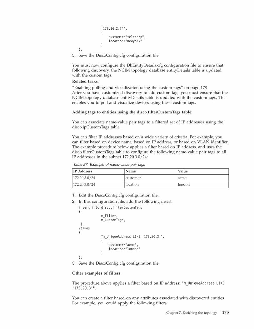
’172.16.2.34’,{
customer="telecorp",location="newyork"
});
3. Save the DiscoConfig.cfg configuration file.
You must now configure the DbEntityDetails.cfg configuration file to ensure that,following discovery, the NCIM topology database entityDetails table is updatedwith the custom tags.Related tasks:“Enabling polling and visualization using the custom tags” on page 178After you have customized discovery to add custom tags you must ensure that theNCIM topology database entityDetails table is updated with the custom tags. Thisenables you to poll and visualize devices using these custom tags.
Adding tags to entities using the disco.filterCustomTags table:
You can associate name-value pair tags to a filtered set of IP addresses using thedisco.ipCustomTags table.
You can filter IP addresses based on a wide variety of criteria. For example, youcan filter based on device name, based on IP address, or based on VLAN identifier.The example procedure below applies a filter based on IP address, and uses thedisco.filterCustomTags table to configure the following name-value pair tags to allIP addresses in the subnet 172.20.3.0/24:
Table 27. Example of name-value pair tags
IP Address Name Value
172.20.3.0/24 customer acme
172.20.3.0/24 location london
1. Edit the DiscoConfig.cfg configuration file.2. In this configuration file, add the following insert:
insert into disco.filterCustomTags(
m_Filter,m_CustomTags,
)values(
"m_UniqueAddress LIKE ’172.20.3’",{
customer="acme",location="london"
});
3. Save the DiscoConfig.cfg configuration file.
Other examples of filters
The procedure above applies a filter based on IP address: "m_UniqueAddress LIKE’172.20.3’".
You can create a filter based on any attributes associated with discovered entities.For example, you could apply the following filters:
Chapter 7. Enriching the topology 175
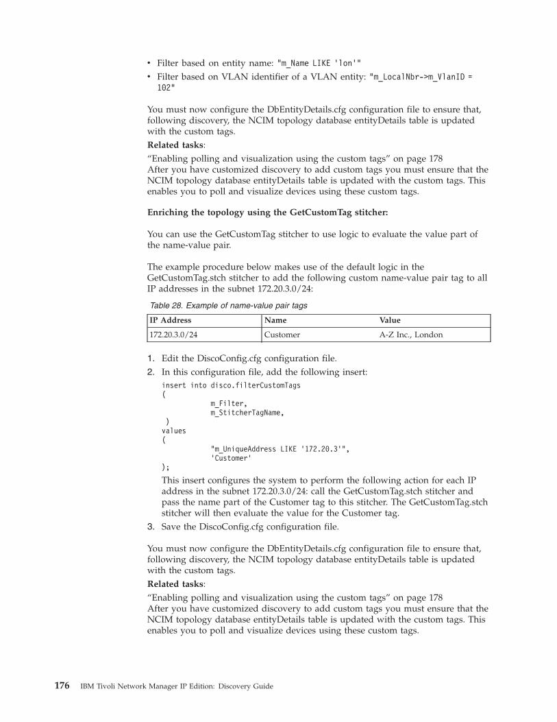
v Filter based on entity name: "m_Name LIKE ’lon’"
v Filter based on VLAN identifier of a VLAN entity: "m_LocalNbr->m_VlanID =102"
You must now configure the DbEntityDetails.cfg configuration file to ensure that,following discovery, the NCIM topology database entityDetails table is updatedwith the custom tags.Related tasks:“Enabling polling and visualization using the custom tags” on page 178After you have customized discovery to add custom tags you must ensure that theNCIM topology database entityDetails table is updated with the custom tags. Thisenables you to poll and visualize devices using these custom tags.
Enriching the topology using the GetCustomTag stitcher:
You can use the GetCustomTag stitcher to use logic to evaluate the value part ofthe name-value pair.
The example procedure below makes use of the default logic in theGetCustomTag.stch stitcher to add the following custom name-value pair tag to allIP addresses in the subnet 172.20.3.0/24:
Table 28. Example of name-value pair tags
IP Address Name Value
172.20.3.0/24 Customer A-Z Inc., London
1. Edit the DiscoConfig.cfg configuration file.2. In this configuration file, add the following insert:
insert into disco.filterCustomTags(
m_Filter,m_StitcherTagName,
)values(
"m_UniqueAddress LIKE ’172.20.3’",’Customer’
);
This insert configures the system to perform the following action for each IPaddress in the subnet 172.20.3.0/24: call the GetCustomTag.stch stitcher andpass the name part of the Customer tag to this stitcher. The GetCustomTag.stchstitcher will then evaluate the value for the Customer tag.
3. Save the DiscoConfig.cfg configuration file.
You must now configure the DbEntityDetails.cfg configuration file to ensure that,following discovery, the NCIM topology database entityDetails table is updatedwith the custom tags.Related tasks:“Enabling polling and visualization using the custom tags” on page 178After you have customized discovery to add custom tags you must ensure that theNCIM topology database entityDetails table is updated with the custom tags. Thisenables you to poll and visualize devices using these custom tags.
176 IBM Tivoli Network Manager IP Edition: Discovery Guide
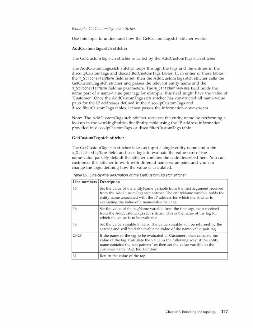
Example: GetCustomTag.stch stitcher:
Use this topic to understand how the GetCustomTag.stch stitcher works.
AddCustomTags.stch stitcher
The GetCustomTag.stch stitcher is called by the AddCustomTags.stch stitcher.
The AddCustomTags.stch stitcher loops through the tags and the entities in thedisco.ipCustomTags and disco.filterCustomTags tables. If, in either of these tables,the m_StitcherTagName field is set, then the AddCustomTags.stch stitcher calls theGetCustomTag.stch stitcher and passes the relevant entity name and them_StitcherTagName field as parameters. The m_StitcherTagName field holds thename part of a name-value pair tag; for example, this field might have the value of'Customer'. Once the AddCustomTags.stch stitcher has constructed all name-valuepairs for the IP addresses defined in the disco.ipCustomTags anddisco.filterCustomTags tables, it then passes the information downstream.
Note: The AddCustomTags.stch stitcher retrieves the entity name by performing alookup in the workingEntities.finalEntity table using the IP address informationprovided in disco.ipCustomTags or disco.filterCustomTags table.
GetCustomTag.stch stitcher
The GetCustomTag.stch stitcher takes as input a single entity name and a them_StitcherTagName field, and uses logic to evaluate the value part of thename-value pair. By default the stitcher contains the code described here. You cancustomize this stitcher to work with different name-value pairs and you canchange the logic defining how the value is calculated.
Table 29. Line-by-line description of the GetCustomTag.stch stitcher
Line numbers Description
15 Set the value of the entityName variable from the first argument receivedfrom the AddCustomTags.stch stitcher. The entityName variable holds theentity name associated with the IP address for which the stitcher isevaluating the value of a name-value pair tag.
16 Set the value of the tagName variable from the first argument receivedfrom the AddCustomTags.stch stitcher. This is the name of the tag forwhich the value is to be evaluated.
18 Set the value variable to zero. The value variable will be returned by thestitcher and will hold the evaluated value of the name-value pair tag.
20-29 If the name of the tag to be evaluated is 'Customer', then calculate thevalue of the tag. Calculate the value in the following way: if the entityname contains the text pattern lon then set the value variable to thecustomer name "A-Z Inc. London".
31 Return the value of the tag.
Chapter 7. Enriching the topology 177
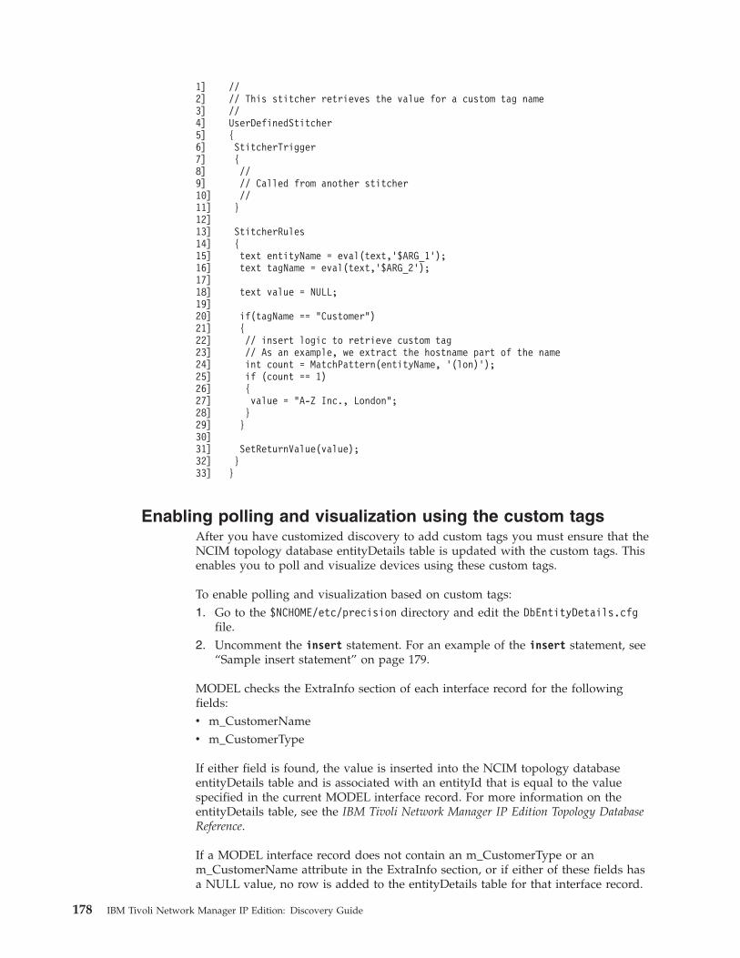
1]2]3]4]5]6]7]8]9]10]11]12]13]14]15]16]17]18]19]20]21]22]23]24]25]26]27]28]29]30]31]32]33]
//// This stitcher retrieves the value for a custom tag name//UserDefinedStitcher{StitcherTrigger{//// Called from another stitcher//}
StitcherRules{text entityName = eval(text,’$ARG_1’);text tagName = eval(text,’$ARG_2’);
text value = NULL;
if(tagName == "Customer"){// insert logic to retrieve custom tag// As an example, we extract the hostname part of the nameint count = MatchPattern(entityName, ’(lon)’);if (count == 1){value = "A-Z Inc., London";}}
SetReturnValue(value);}}
Enabling polling and visualization using the custom tagsAfter you have customized discovery to add custom tags you must ensure that theNCIM topology database entityDetails table is updated with the custom tags. Thisenables you to poll and visualize devices using these custom tags.
To enable polling and visualization based on custom tags:1. Go to the $NCHOME/etc/precision directory and edit the DbEntityDetails.cfg
file.2. Uncomment the insert statement. For an example of the insert statement, see
“Sample insert statement” on page 179.
MODEL checks the ExtraInfo section of each interface record for the followingfields:v m_CustomerNamev m_CustomerType
If either field is found, the value is inserted into the NCIM topology databaseentityDetails table and is associated with an entityId that is equal to the valuespecified in the current MODEL interface record. For more information on theentityDetails table, see the IBM Tivoli Network Manager IP Edition Topology DatabaseReference.
If a MODEL interface record does not contain an m_CustomerType or anm_CustomerName attribute in the ExtraInfo section, or if either of these fields hasa NULL value, no row is added to the entityDetails table for that interface record.
178 IBM Tivoli Network Manager IP Edition: Discovery Guide
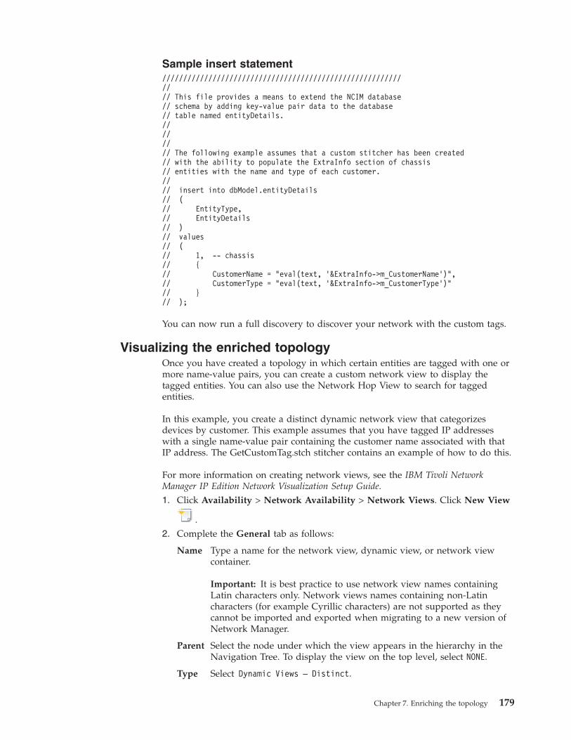
Sample insert statement///////////////////////////////////////////////////////////// This file provides a means to extend the NCIM database// schema by adding key-value pair data to the database// table named entityDetails.//////// The following example assumes that a custom stitcher has been created// with the ability to populate the ExtraInfo section of chassis// entities with the name and type of each customer.//// insert into dbModel.entityDetails// (// EntityType,// EntityDetails// )// values// (// 1, -- chassis// {// CustomerName = "eval(text, ’&ExtraInfo->m_CustomerName’)",// CustomerType = "eval(text, ’&ExtraInfo->m_CustomerType’)"// }// );
You can now run a full discovery to discover your network with the custom tags.
Visualizing the enriched topologyOnce you have created a topology in which certain entities are tagged with one ormore name-value pairs, you can create a custom network view to display thetagged entities. You can also use the Network Hop View to search for taggedentities.
In this example, you create a distinct dynamic network view that categorizesdevices by customer. This example assumes that you have tagged IP addresseswith a single name-value pair containing the customer name associated with thatIP address. The GetCustomTag.stch stitcher contains an example of how to do this.
For more information on creating network views, see the IBM Tivoli NetworkManager IP Edition Network Visualization Setup Guide.1. Click Availability > Network Availability > Network Views. Click New View
.2. Complete the General tab as follows:
Name Type a name for the network view, dynamic view, or network viewcontainer.
Important: It is best practice to use network view names containingLatin characters only. Network views names containing non-Latincharacters (for example Cyrillic characters) are not supported as theycannot be imported and exported when migrating to a new version ofNetwork Manager.
Parent Select the node under which the view appears in the hierarchy in theNavigation Tree. To display the view on the top level, select NONE.
Type Select Dynamic Views – Distinct.
Chapter 7. Enriching the topology 179
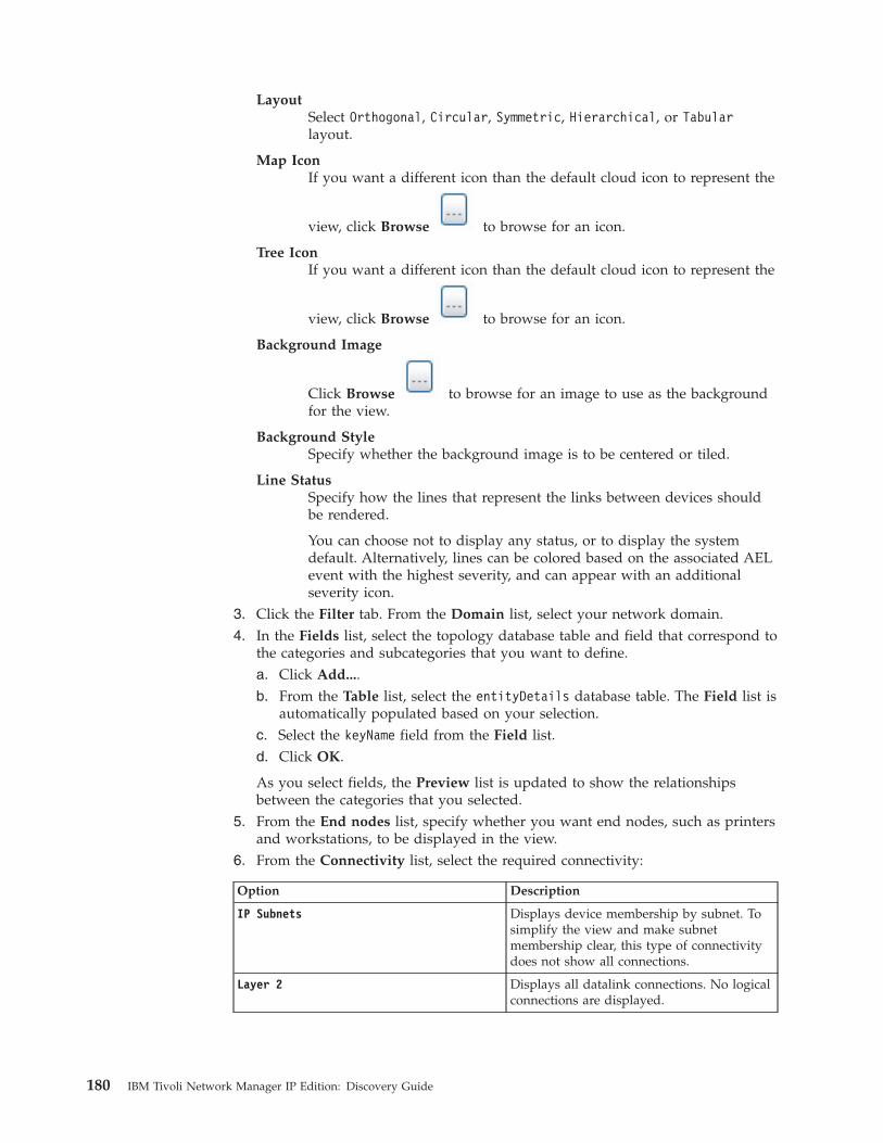
LayoutSelect Orthogonal, Circular, Symmetric, Hierarchical, or Tabularlayout.
Map IconIf you want a different icon than the default cloud icon to represent the
view, click Browse to browse for an icon.
Tree IconIf you want a different icon than the default cloud icon to represent the
view, click Browse to browse for an icon.
Background Image
Click Browse to browse for an image to use as the backgroundfor the view.
Background StyleSpecify whether the background image is to be centered or tiled.
Line StatusSpecify how the lines that represent the links between devices shouldbe rendered.
You can choose not to display any status, or to display the systemdefault. Alternatively, lines can be colored based on the associated AELevent with the highest severity, and can appear with an additionalseverity icon.
3. Click the Filter tab. From the Domain list, select your network domain.4. In the Fields list, select the topology database table and field that correspond to
the categories and subcategories that you want to define.a. Click Add....b. From the Table list, select the entityDetails database table. The Field list is
automatically populated based on your selection.c. Select the keyName field from the Field list.d. Click OK.
As you select fields, the Preview list is updated to show the relationshipsbetween the categories that you selected.
5. From the End nodes list, specify whether you want end nodes, such as printersand workstations, to be displayed in the view.
6. From the Connectivity list, select the required connectivity:
Option Description
IP Subnets Displays device membership by subnet. Tosimplify the view and make subnetmembership clear, this type of connectivitydoes not show all connections.
Layer 2 Displays all datalink connections. No logicalconnections are displayed.
180 IBM Tivoli Network Manager IP Edition: Discovery Guide
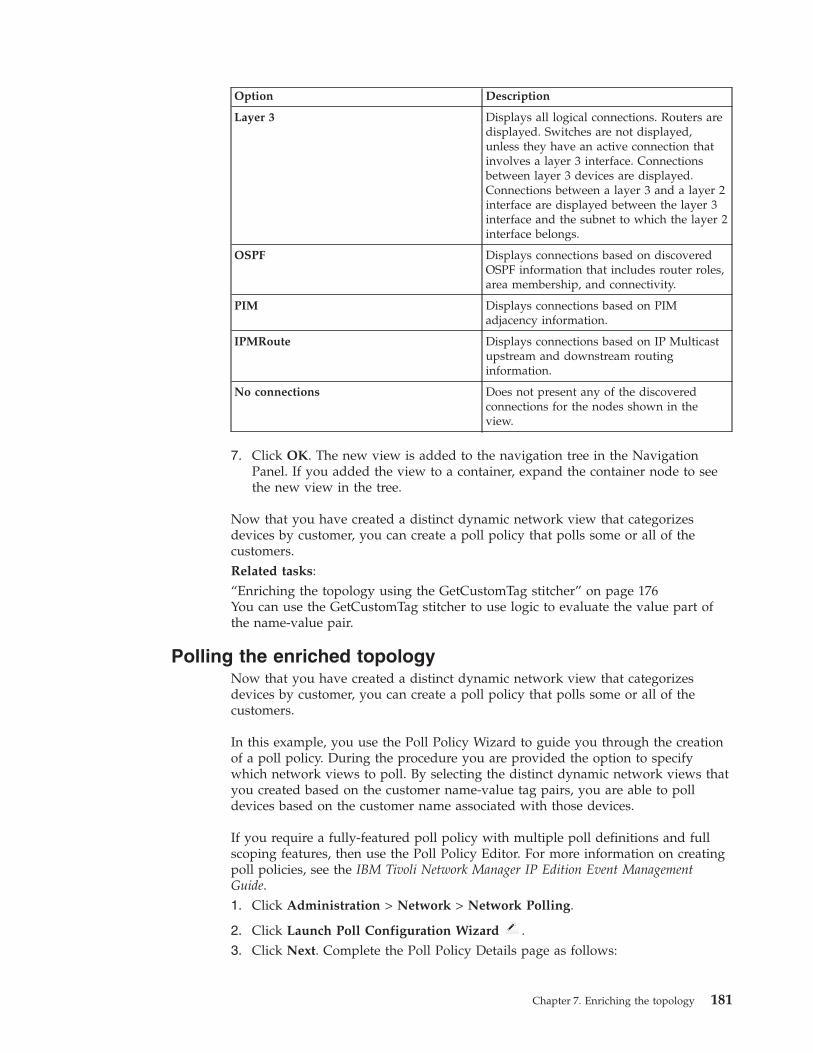
Option Description
Layer 3 Displays all logical connections. Routers aredisplayed. Switches are not displayed,unless they have an active connection thatinvolves a layer 3 interface. Connectionsbetween layer 3 devices are displayed.Connections between a layer 3 and a layer 2interface are displayed between the layer 3interface and the subnet to which the layer 2interface belongs.
OSPF Displays connections based on discoveredOSPF information that includes router roles,area membership, and connectivity.
PIM Displays connections based on PIMadjacency information.
IPMRoute Displays connections based on IP Multicastupstream and downstream routinginformation.
No connections Does not present any of the discoveredconnections for the nodes shown in theview.
7. Click OK. The new view is added to the navigation tree in the NavigationPanel. If you added the view to a container, expand the container node to seethe new view in the tree.
Now that you have created a distinct dynamic network view that categorizesdevices by customer, you can create a poll policy that polls some or all of thecustomers.Related tasks:“Enriching the topology using the GetCustomTag stitcher” on page 176You can use the GetCustomTag stitcher to use logic to evaluate the value part ofthe name-value pair.
Polling the enriched topologyNow that you have created a distinct dynamic network view that categorizesdevices by customer, you can create a poll policy that polls some or all of thecustomers.
In this example, you use the Poll Policy Wizard to guide you through the creationof a poll policy. During the procedure you are provided the option to specifywhich network views to poll. By selecting the distinct dynamic network views thatyou created based on the customer name-value tag pairs, you are able to polldevices based on the customer name associated with those devices.
If you require a fully-featured poll policy with multiple poll definitions and fullscoping features, then use the Poll Policy Editor. For more information on creatingpoll policies, see the IBM Tivoli Network Manager IP Edition Event ManagementGuide.1. Click Administration > Network > Network Polling.
2. Click Launch Poll Configuration Wizard .3. Click Next. Complete the Poll Policy Details page as follows:
Chapter 7. Enriching the topology 181
Name Specify a name for the poll policy. Only alphanumeric characters,spaces and underscores are allowed.
IntervalSpecify the required interval in seconds between poll operations. Clickthe arrows to change the value.
Poll EnabledSpecify whether the poll should be enabled. The poll is enabled bydefault. To disable the poll, clear this check box.
Store Poll DataSelect this check box to store the poll data so that it can besubsequently retrieved for reporting. The data is stored in thencpolldata database.
Restriction: Storage of polled data is not supported for the CiscoRemote Ping, the Juniper Remote Ping, and the Generic Threshold polldefinitions.
DefinitionSelect a poll definition from the list.
4. Click Next. On the Network Views page, navigate in the network views tree tothe node containing the distinct dynamic network views that you created. Openthe node and select the customer devices that you want to poll using this pollpolicy.
5. Click Next. On the Poll Policy Summary page, review the information that youspecified and click Finish.
182 IBM Tivoli Network Manager IP Edition: Discovery Guide
Appendix A. Discovery databases
There are various specialized databases that are used by ncp_disco, the componentthat discovers network device existence and connectivity, and by ncp_model, thecomponent that manages, stores, and distributes the discovered network topology.
The ncp_disco component and ncp_model component store configuration,management, and operational information in databases. You can interrogate thesedatabases by logging into the DISCO or MODEL service using the OQL ServiceProvider.
The ncp_disco databases can either be active or passive. When data is inserted intoan active database, an action is automatically triggered; for example, another tableis populated with data, or a script or stitcher is launched.Related concepts:“Filters” on page 5Use prediscovery filters to increase the efficiency of discovery and post-discoveryfilters to prevent instantiation of devices.Related tasks:“Setting discovery filters” on page 28Use filters to filter out devices either before discovery or after discovery. You canfilter out devices based on a variety of criteria, including location, technology, andmanufacturer. Filters provide additional restrictions to those defined in the scopezones.“Scoping discovery” on page 17To scope the discovery, define the zones of the network (that is, subnet ranges) thatyou want to include in the discovery, and the zones that you want to exclude.
Discovery engine databaseUse the Discovery engine (ncp_disco) database to configure the general options forthe discovery process, and to track the discovery process.
The Discovery engine database, disco, is defined in $NCHOME/etc/precision/DiscoSchema.cfg. Its fully qualified database table names are: disco.config;disco.managedProcesses; disco.status; disco.agents; disco.NATStatus.
disco.config tableThe config table configures the general operation of the discovery process.
Table 30. disco.config database table schema
Column name Constraints Data type Description
m_NothngFndPeriod Float The maximum time lapse, in seconds, betweenthe discovery of one device and the discoveryof the next device in the device discoveryphase.
m_PendingPerCent Integer The maximum allowed ratio of pendingdevices to processing devices. A breach of thisthreshold condition instigates a full discovery(rather than a partial rediscovery).
© Copyright IBM Corp. 2006, 2013 183
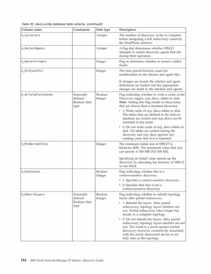
Table 30. disco.config database table schema (continued)
Column name Constraints Data type Description
m_CycleLimit Integer The number of discovery cycles to completebefore instigating a full rediscovery (used bythe FinalPhase stitcher).
m_RestartAgents Integer A flag that determines whether DISCOattempts to restart discovery agents that failduring their operation.
m_RestartFinders Integer Flag to determine whether to restart a failedfinder.
m_DirScanIntvl Integer The time period between scans formodifications to the stitcher and agent files.
If changes are found, the stitcher and agentdefinitions are loaded and the appropriatechanges are made to the stitchers and agents.
m_WriteTablesToCache ExternallydefinedBoolean datatype
BooleanInteger
Flag indicating whether to write a cache of theDiscovery engine, ncp_disco, tables to disk.Note: Setting this flag results in discoveriesthat are slower than a standard discovery.
v 1: Write cache of ncp_disco tables to disk.The tables that are defined in the failoverdatabase are cached and ncp_disco can berestarted at any point.
v 0: Do not write cache of ncp_disco tables todisk. No tables are cached during thediscovery and ncp_disco ignores anyexisting cache files if it is restarted.
m_MinResidentSize Integer The minimum initial size of DISCO inkilobytes (KB). The maximum value that youcan specify is 500 MB (512 000 KB).
Specifying an initial value speeds up thediscovery by allocating the memory of DISCOin one block.
m_UseContext BooleanInteger
Flag indicating whether this is acontext-sensitive discovery.
v 1: Specifies a context-sensitive discovery.
v 0: Specifies that this is not acontext-sensitive discovery.
m_RebuildLayers ExternallydefinedBoolean datatype
BooleanInteger
Flag indicating whether to rebuild topologylayers after partial rediscovery.
v 1: Rebuild the layers. After partialrediscovery, topology layers stitchers arerun. Partial rediscovery takes longer butresults in a complete topology.
v 0: Do not rebuild the layers. After partialrediscovery, topology layers stitchers are notrun. The result is a much quicker partialdiscovery; however, connectivity associatedwith the newly discovered device is notfully seen in the topology.
184 IBM Tivoli Network Manager IP Edition: Discovery Guide
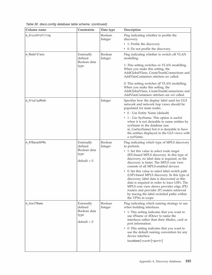
Table 30. disco.config database table schema (continued)
Column name Constraints Data type Description
m_DiscoProfiling BooleanInteger
Flag indicating whether to profile thediscovery.
v 1: Profile the discovery.
v 0: Do not profile the discovery.
m_ModelVlans ExternallydefinedBoolean datatype
BooleanInteger
Flag indicating whether to switch off VLANmodelling.
1: This setting switches on VLAN modelling.When you make this setting, theAddGlobalVlans, CreateTrunkConnections andAddVlanContainers stitchers are called.
0: This setting switches off VLAN modelling.When you make this setting, theAddGlobalVlans, CreateTrunkConnections andAddVlanContainers stitchers are not called.
m_DisplayMode Integer Specifies how the display label used for GUInetwork and network hop views should bepopulated for main nodes.
v 0 - Use Entity Name (default)
v 1 - Use SysName. This option is usefulwhen it is not desirable to name entities bysysName in the database (seem_UseSysName) but it is desirable to havethe entities displayed in the GUI views witha sysName.
m_RTBasedVPNs ExternallydefinedBoolean datatype
default = 0
BooleanInteger
Flag indicating which type of MPLS discoveryto perform.
v 1: Set this value to select route target(RT)-based MPLS discovery. In this type ofdiscovery, no label data is required, so thediscovery is faster. The MPLS core viewconsists of all MPLS-enabled devices.
v 0: Set this value to select label switch path(LSP)-based MPLS discovery. In this type ofdiscovery, label data is discovered as thisdata is required in order to trace LSPs. TheMPLS core view shows provider edge (PE)routers and provider (P) routers retrievedby tracing the label switched paths withinthe VPNs in scope.
m_UseIfName ExternallydefinedBoolean datatype
default = 0
BooleanInteger
Flag indicating which naming strategy to usewhen building interfaces.
v 1: This setting indicates that you want touse ifName or ifDescr to name theinterfaces rather than their ifIndex, card orport information.
v 0: This setting indicates that you want touse the default naming convention for anydevice interface:
baseName[<card>[<port>]
Appendix A. Discovery databases 185
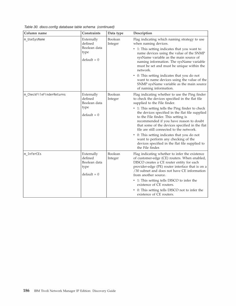
Table 30. disco.config database table schema (continued)
Column name Constraints Data type Description
m_UseSysName ExternallydefinedBoolean datatype
default = 0
BooleanInteger
Flag indicating which naming strategy to usewhen naming devices.
v 1: This setting indicates that you want toname devices using the value of the SNMPsysName variable as the main source ofnaming information. The sysName variablemust be set and must be unique within thenetwork.
v 0: This setting indicates that you do notwant to name devices using the value of theSNMP sysName variable as the main sourceof naming information.
m_CheckFileFinderReturns ExternallydefinedBoolean datatype
default = 0
BooleanInteger
Flag indicating whether to use the Ping finderto check the devices specified in the flat filesupplied to the File finder.
v 1: This setting tells the Ping finder to checkthe devices specified in the flat file suppliedto the File finder. This setting isrecommended if you have reason to doubtthat some of the devices specified in the flatfile are still connected to the network.
v 0: This setting indicates that you do notwant to perform any checking of thedevices specified in the flat file supplied tothe File finder.
m_InferCEs ExternallydefinedBoolean datatype
default = 0
BooleanInteger
Flag indicating whether to infer the existenceof customer-edge (CE) routers. When enabled,DISCO creates a CE router entity for eachprovider-edge (PE) router interface that is on a/30 subnet and does not have CE informationfrom another source.
v 1: This setting tells DISCO to infer theexistence of CE routers.
v 0: This setting tells DISCO not to infer theexistence of CE routers.
186 IBM Tivoli Network Manager IP Edition: Discovery Guide
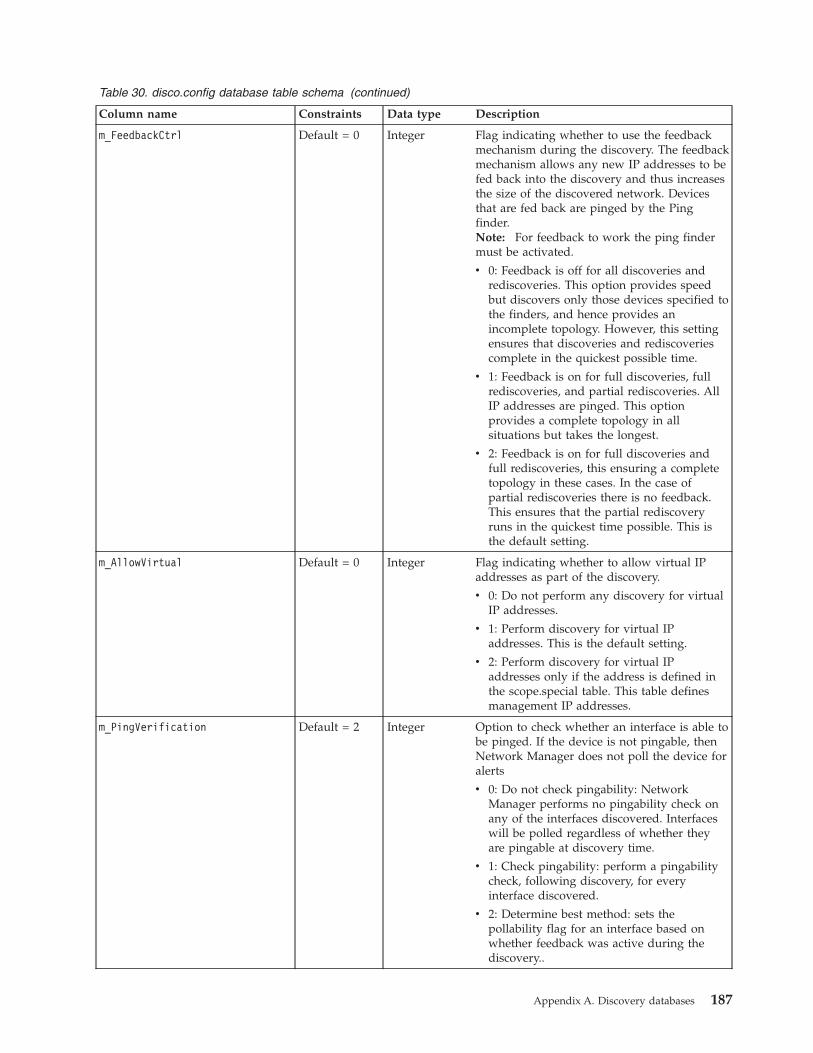
Table 30. disco.config database table schema (continued)
Column name Constraints Data type Description
m_FeedbackCtrl Default = 0 Integer Flag indicating whether to use the feedbackmechanism during the discovery. The feedbackmechanism allows any new IP addresses to befed back into the discovery and thus increasesthe size of the discovered network. Devicesthat are fed back are pinged by the Pingfinder.Note: For feedback to work the ping findermust be activated.
v 0: Feedback is off for all discoveries andrediscoveries. This option provides speedbut discovers only those devices specified tothe finders, and hence provides anincomplete topology. However, this settingensures that discoveries and rediscoveriescomplete in the quickest possible time.
v 1: Feedback is on for full discoveries, fullrediscoveries, and partial rediscoveries. AllIP addresses are pinged. This optionprovides a complete topology in allsituations but takes the longest.
v 2: Feedback is on for full discoveries andfull rediscoveries, this ensuring a completetopology in these cases. In the case ofpartial rediscoveries there is no feedback.This ensures that the partial rediscoveryruns in the quickest time possible. This isthe default setting.
m_AllowVirtual Default = 0 Integer Flag indicating whether to allow virtual IPaddresses as part of the discovery.
v 0: Do not perform any discovery for virtualIP addresses.
v 1: Perform discovery for virtual IPaddresses. This is the default setting.
v 2: Perform discovery for virtual IPaddresses only if the address is defined inthe scope.special table. This table definesmanagement IP addresses.
m_PingVerification Default = 2 Integer Option to check whether an interface is able tobe pinged. If the device is not pingable, thenNetwork Manager does not poll the device foralerts
v 0: Do not check pingability: NetworkManager performs no pingability check onany of the interfaces discovered. Interfaceswill be polled regardless of whether theyare pingable at discovery time.
v 1: Check pingability: perform a pingabilitycheck, following discovery, for everyinterface discovered.
v 2: Determine best method: sets thepollability flag for an interface based onwhether feedback was active during thediscovery..
Appendix A. Discovery databases 187
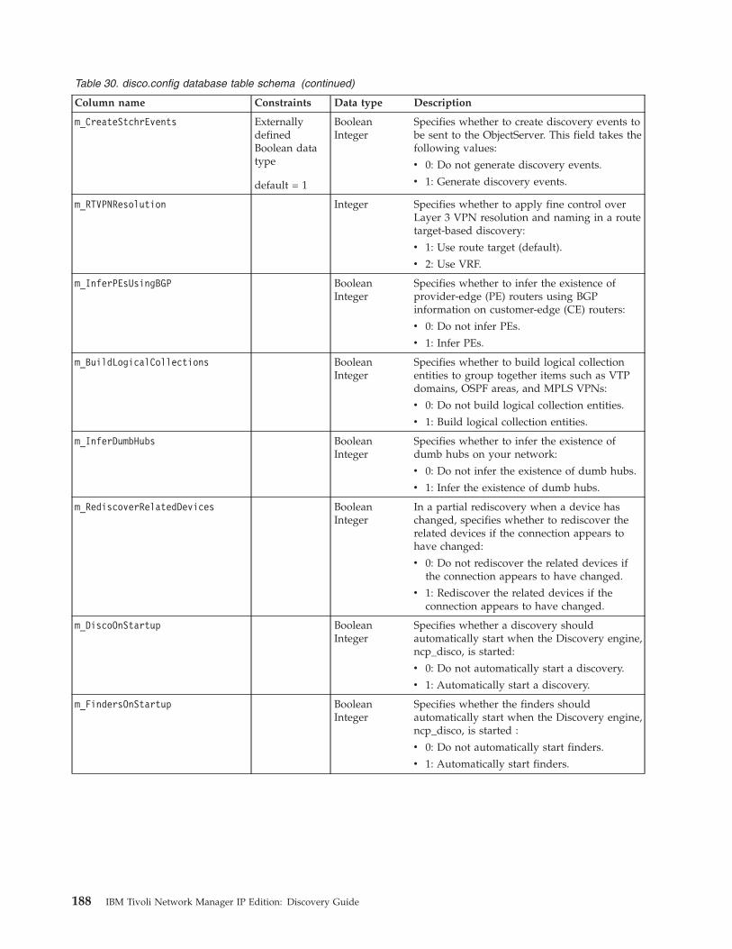
Table 30. disco.config database table schema (continued)
Column name Constraints Data type Description
m_CreateStchrEvents ExternallydefinedBoolean datatype
default = 1
BooleanInteger
Specifies whether to create discovery events tobe sent to the ObjectServer. This field takes thefollowing values:
v 0: Do not generate discovery events.
v 1: Generate discovery events.
m_RTVPNResolution Integer Specifies whether to apply fine control overLayer 3 VPN resolution and naming in a routetarget-based discovery:
v 1: Use route target (default).
v 2: Use VRF.
m_InferPEsUsingBGP BooleanInteger
Specifies whether to infer the existence ofprovider-edge (PE) routers using BGPinformation on customer-edge (CE) routers:
v 0: Do not infer PEs.
v 1: Infer PEs.
m_BuildLogicalCollections BooleanInteger
Specifies whether to build logical collectionentities to group together items such as VTPdomains, OSPF areas, and MPLS VPNs:
v 0: Do not build logical collection entities.
v 1: Build logical collection entities.
m_InferDumbHubs BooleanInteger
Specifies whether to infer the existence ofdumb hubs on your network:
v 0: Do not infer the existence of dumb hubs.
v 1: Infer the existence of dumb hubs.
m_RediscoverRelatedDevices BooleanInteger
In a partial rediscovery when a device haschanged, specifies whether to rediscover therelated devices if the connection appears tohave changed:
v 0: Do not rediscover the related devices ifthe connection appears to have changed.
v 1: Rediscover the related devices if theconnection appears to have changed.
m_DiscoOnStartup BooleanInteger
Specifies whether a discovery shouldautomatically start when the Discovery engine,ncp_disco, is started:
v 0: Do not automatically start a discovery.
v 1: Automatically start a discovery.
m_FindersOnStartup BooleanInteger
Specifies whether the finders shouldautomatically start when the Discovery engine,ncp_disco, is started :
v 0: Do not automatically start finders.
v 1: Automatically start finders.
188 IBM Tivoli Network Manager IP Edition: Discovery Guide
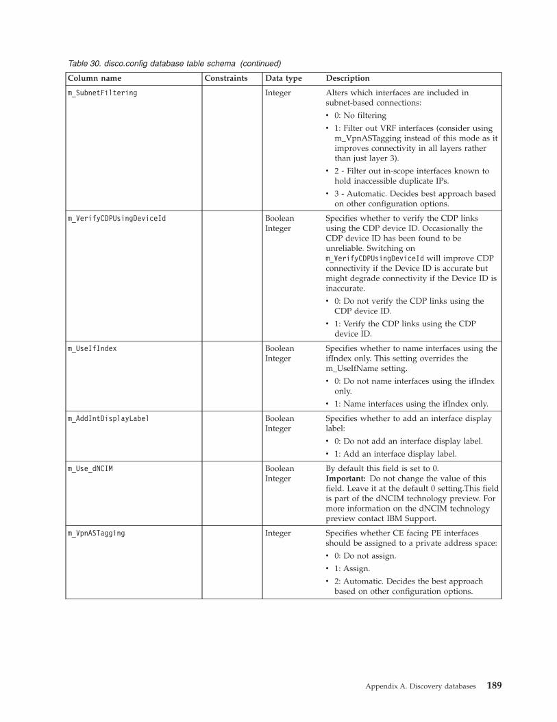
Table 30. disco.config database table schema (continued)
Column name Constraints Data type Description
m_SubnetFiltering Integer Alters which interfaces are included insubnet-based connections:
v 0: No filtering
v 1: Filter out VRF interfaces (consider usingm_VpnASTagging instead of this mode as itimproves connectivity in all layers ratherthan just layer 3).
v 2 - Filter out in-scope interfaces known tohold inaccessible duplicate IPs.
v 3 - Automatic. Decides best approach basedon other configuration options.
m_VerifyCDPUsingDeviceId BooleanInteger
Specifies whether to verify the CDP linksusing the CDP device ID. Occasionally theCDP device ID has been found to beunreliable. Switching onm_VerifyCDPUsingDeviceId will improve CDPconnectivity if the Device ID is accurate butmight degrade connectivity if the Device ID isinaccurate.
v 0: Do not verify the CDP links using theCDP device ID.
v 1: Verify the CDP links using the CDPdevice ID.
m_UseIfIndex BooleanInteger
Specifies whether to name interfaces using theifIndex only. This setting overrides them_UseIfName setting.
v 0: Do not name interfaces using the ifIndexonly.
v 1: Name interfaces using the ifIndex only.
m_AddIntDisplayLabel BooleanInteger
Specifies whether to add an interface displaylabel:
v 0: Do not add an interface display label.
v 1: Add an interface display label.
m_Use_dNCIM BooleanInteger
By default this field is set to 0.Important: Do not change the value of thisfield. Leave it at the default 0 setting.This fieldis part of the dNCIM technology preview. Formore information on the dNCIM technologypreview contact IBM Support.
m_VpnASTagging Integer Specifies whether CE facing PE interfacesshould be assigned to a private address space:
v 0: Do not assign.
v 1: Assign.
v 2: Automatic. Decides the best approachbased on other configuration options.
Appendix A. Discovery databases 189
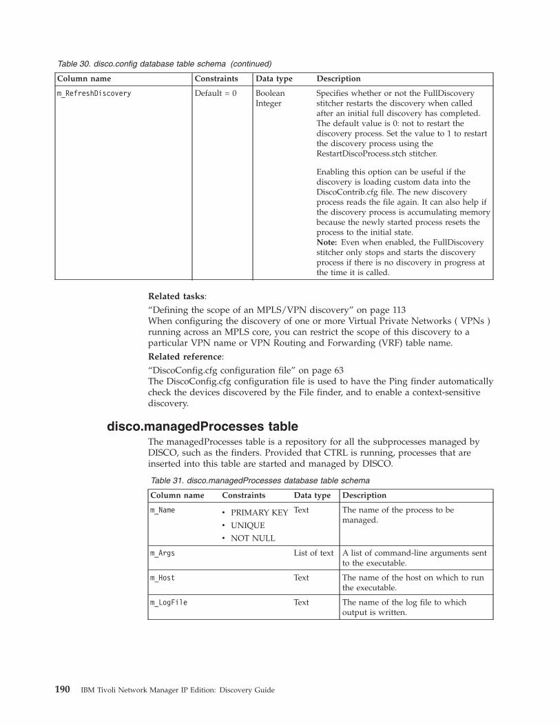
Table 30. disco.config database table schema (continued)
Column name Constraints Data type Description
m_RefreshDiscovery Default = 0 BooleanInteger
Specifies whether or not the FullDiscoverystitcher restarts the discovery when calledafter an initial full discovery has completed.The default value is 0: not to restart thediscovery process. Set the value to 1 to restartthe discovery process using theRestartDiscoProcess.stch stitcher.
Enabling this option can be useful if thediscovery is loading custom data into theDiscoContrib.cfg file. The new discoveryprocess reads the file again. It can also help ifthe discovery process is accumulating memorybecause the newly started process resets theprocess to the initial state.Note: Even when enabled, the FullDiscoverystitcher only stops and starts the discoveryprocess if there is no discovery in progress atthe time it is called.
Related tasks:“Defining the scope of an MPLS/VPN discovery” on page 113When configuring the discovery of one or more Virtual Private Networks ( VPNs )running across an MPLS core, you can restrict the scope of this discovery to aparticular VPN name or VPN Routing and Forwarding (VRF) table name.Related reference:“DiscoConfig.cfg configuration file” on page 63The DiscoConfig.cfg configuration file is used to have the Ping finder automaticallycheck the devices discovered by the File finder, and to enable a context-sensitivediscovery.
disco.managedProcesses tableThe managedProcesses table is a repository for all the subprocesses managed byDISCO, such as the finders. Provided that CTRL is running, processes that areinserted into this table are started and managed by DISCO.
Table 31. disco.managedProcesses database table schema
Column name Constraints Data type Description
m_Name v PRIMARY KEY
v UNIQUE
v NOT NULL
Text The name of the process to bemanaged.
m_Args List of text A list of command-line arguments sentto the executable.
m_Host Text The name of the host on which to runthe executable.
m_LogFile Text The name of the log file to whichoutput is written.
190 IBM Tivoli Network Manager IP Edition: Discovery Guide
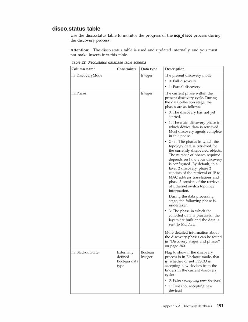
disco.status tableUse the disco.status table to monitor the progress of the ncp_disco process duringthe discovery process.
Attention: The disco.status table is used and updated internally, and you mustnot make inserts into this table.
Table 32. disco.status database table schema
Column name Constraints Data type Description
m_DiscoveryMode Integer The present discovery mode:
v 0: Full discovery
v 1: Partial discovery
m_Phase Integer The current phase within thepresent discovery cycle. Duringthe data collection stage, thephases are as follows:
v 0: The discovery has not yetstarted.
v 1: The main discovery phase inwhich device data is retrieved.Most discovery agents completein this phase.
v 2 - n: The phases in which thetopology data is retrieved forthe currently discovered objects.The number of phases requireddepends on how your discoveryis configured. By default, in alayer 2 discovery, phase 2consists of the retrieval of IP toMAC address translations andphase 3 consists of the retrievalof Ethernet switch topologyinformation.
During the data processingstage, the following phase isundertaken.
v 3: The phase in which thecollected data is processed; thelayers are built and the data issent to MODEL.
More detailed information aboutthe discovery phases can be foundin “Discovery stages and phases”on page 280.
m_BlackoutState ExternallydefinedBoolean datatype
BooleanInteger
Flag to show if the discoveryprocess is in Blackout mode, thatis, whether or not DISCO isaccepting new devices from thefinders in the current discoverycycle:
v 0: False (accepting new devices)
v 1: True (not accepting newdevices)
Appendix A. Discovery databases 191
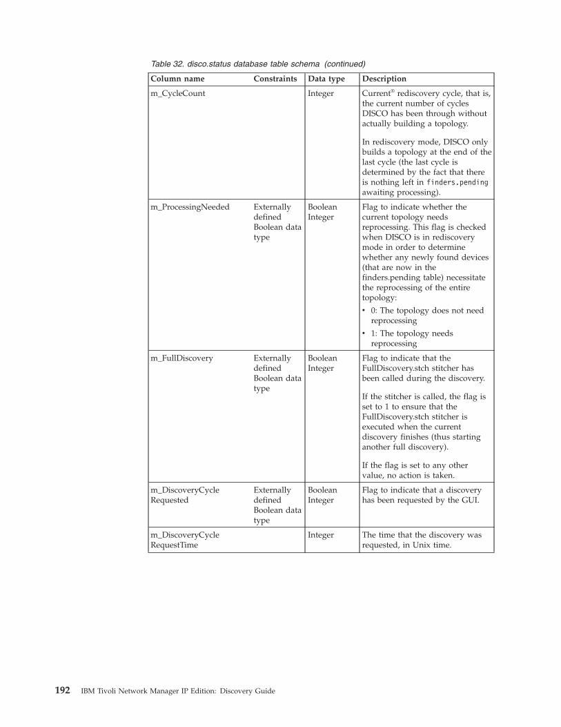
Table 32. disco.status database table schema (continued)
Column name Constraints Data type Description
m_CycleCount Integer Current® rediscovery cycle, that is,the current number of cyclesDISCO has been through withoutactually building a topology.
In rediscovery mode, DISCO onlybuilds a topology at the end of thelast cycle (the last cycle isdetermined by the fact that thereis nothing left in finders.pendingawaiting processing).
m_ProcessingNeeded ExternallydefinedBoolean datatype
BooleanInteger
Flag to indicate whether thecurrent topology needsreprocessing. This flag is checkedwhen DISCO is in rediscoverymode in order to determinewhether any newly found devices(that are now in thefinders.pending table) necessitatethe reprocessing of the entiretopology:
v 0: The topology does not needreprocessing
v 1: The topology needsreprocessing
m_FullDiscovery ExternallydefinedBoolean datatype
BooleanInteger
Flag to indicate that theFullDiscovery.stch stitcher hasbeen called during the discovery.
If the stitcher is called, the flag isset to 1 to ensure that theFullDiscovery.stch stitcher isexecuted when the currentdiscovery finishes (thus startinganother full discovery).
If the flag is set to any othervalue, no action is taken.
m_DiscoveryCycleRequested
ExternallydefinedBoolean datatype
BooleanInteger
Flag to indicate that a discoveryhas been requested by the GUI.
m_DiscoveryCycleRequestTime
Integer The time that the discovery wasrequested, in Unix time.
192 IBM Tivoli Network Manager IP Edition: Discovery Guide
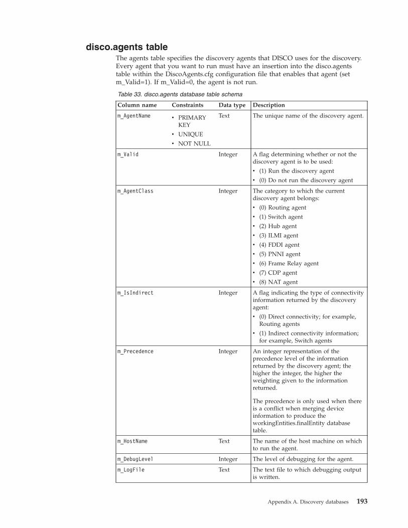
disco.agents tableThe agents table specifies the discovery agents that DISCO uses for the discovery.Every agent that you want to run must have an insertion into the disco.agentstable within the DiscoAgents.cfg configuration file that enables that agent (setm_Valid=1). If m_Valid=0, the agent is not run.
Table 33. disco.agents database table schema
Column name Constraints Data type Description
m_AgentName v PRIMARYKEY
v UNIQUE
v NOT NULL
Text The unique name of the discovery agent.
m_Valid Integer A flag determining whether or not thediscovery agent is to be used:
v (1) Run the discovery agent
v (0) Do not run the discovery agent
m_AgentClass Integer The category to which the currentdiscovery agent belongs:
v (0) Routing agent
v (1) Switch agent
v (2) Hub agent
v (3) ILMI agent
v (4) FDDI agent
v (5) PNNI agent
v (6) Frame Relay agent
v (7) CDP agent
v (8) NAT agent
m_IsIndirect Integer A flag indicating the type of connectivityinformation returned by the discoveryagent:
v (0) Direct connectivity; for example,Routing agents
v (1) Indirect connectivity information;for example, Switch agents
m_Precedence Integer An integer representation of theprecedence level of the informationreturned by the discovery agent; thehigher the integer, the higher theweighting given to the informationreturned.
The precedence is only used when thereis a conflict when merging deviceinformation to produce theworkingEntities.finalEntity databasetable.
m_HostName Text The name of the host machine on whichto run the agent.
m_DebugLevel Integer The level of debugging for the agent.
m_LogFile Text The text file to which debugging outputis written.
Appendix A. Discovery databases 193

Table 33. disco.agents database table schema (continued)
Column name Constraints Data type Description
m_NumThreads Integer The number of threads this agent runs. Ifnot specified, the default number is 10;the maximum allowed is 900.
m_ValidOnPartial Integer Specifies whether the agent is to be usedon a partial discovery:
v 0: Agent is not to be used in a partialdiscovery.
v 1: Agent is to be used in a partialdiscovery.
m_MessageLevel Text Specifies the message level (the default iswarn). Options include:
v debug
v info
v warn
v error
v fatal
The disco.agents table also indicates agent precedence, which can be used whenmerging device information to produce the workingEntities.finalEntity table.Precedence determines which records are used when duplicate or conflictingrecords are reported by different discovery agents.
The following precedence applies:v The Details agent has the lowest precedence because it is designed to retrieve
only basic device information.v Routing agents have the next highest precedence. Their connectivity information
is at the IP layer only, however, so it is not as accurate as that returned by theswitching agents.
v Switching agents have next-highest precedence because they can returninformation on the media layer (layer 2), which is more accurate than layer 3information.
194 IBM Tivoli Network Manager IP Edition: Discovery Guide
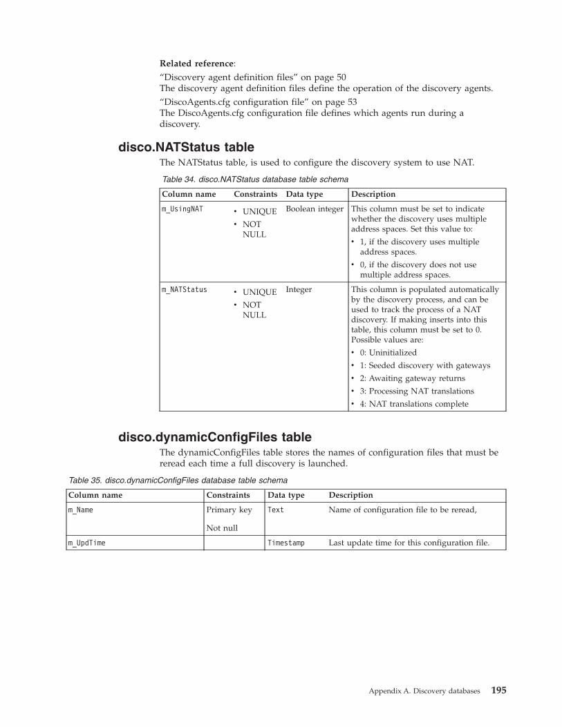
Related reference:“Discovery agent definition files” on page 50The discovery agent definition files define the operation of the discovery agents.“DiscoAgents.cfg configuration file” on page 53The DiscoAgents.cfg configuration file defines which agents run during adiscovery.
disco.NATStatus tableThe NATStatus table, is used to configure the discovery system to use NAT.
Table 34. disco.NATStatus database table schema
Column name Constraints Data type Description
m_UsingNAT v UNIQUE
v NOTNULL
Boolean integer This column must be set to indicatewhether the discovery uses multipleaddress spaces. Set this value to:
v 1, if the discovery uses multipleaddress spaces.
v 0, if the discovery does not usemultiple address spaces.
m_NATStatus v UNIQUE
v NOTNULL
Integer This column is populated automaticallyby the discovery process, and can beused to track the process of a NATdiscovery. If making inserts into thistable, this column must be set to 0.Possible values are:
v 0: Uninitialized
v 1: Seeded discovery with gateways
v 2: Awaiting gateway returns
v 3: Processing NAT translations
v 4: NAT translations complete
disco.dynamicConfigFiles tableThe dynamicConfigFiles table stores the names of configuration files that must bereread each time a full discovery is launched.
Table 35. disco.dynamicConfigFiles database table schema
Column name Constraints Data type Description
m_Name Primary key
Not null
Text Name of configuration file to be reread,
m_UpdTime Timestamp Last update time for this configuration file.
Appendix A. Discovery databases 195
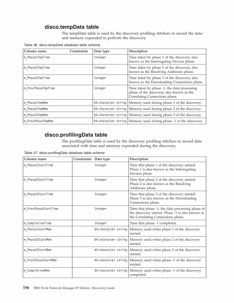
disco.tempData tableThe tempData table is used by the discovery profiling stitchers to record the timeand memory expended to perform the discovery.
Table 36. disco.tempData database table schema
Column name Constraints Data type Description
m_Phase1TmpTime Integer Time taken by phase 1 of the discovery, alsoknown as the Interrogating Devices phase.
m_Phase2TmpTime Integer Time taken by phase 2 of the discovery, alsoknown as the Resolving Addresses phase.
m_Phase3TmpTime Integer Time taken by phase 3 of the discovery, alsoknown as the Downloading Connections phase.
m_ProcPhaseTmpTime Integer Time taken by phase -1, the data processingphase of the discovery, also known as theCorrelating Connections phase.
m_Phase1TmpMem 64-character string Memory used during phase 1 of the discovery.
m_Phase2TmpMem 64-character string Memory used during phase 2 of the discovery.
m_Phase3TmpMem 64-character string Memory used during phase 3 of the discovery.
m_ProcPhaseTmpMem 64-character string Memory used during phase -1 of the discovery.
disco.profilingData tableThe profilingData table is used by the discovery profiling stitchers to record dataassociated with time and memory expended during the discovery.
Table 37. disco.profilingData database table schema
Column name Constraints Data type Description
m_Phase1StartTime Integer Time that phase 1 of the discovery started.Phase 1 is also known as the InterrogatingDevices phase.
m_Phase2StartTime Integer Time that phase 2 of the discovery started.Phase 2 is also known as the ResolvingAddresses phase.
m_Phase3StartTime Integer Time that phase 3 of the discovery started.Phase 3 is also known as the DownloadingConnections phase.
m_ProcPhaseStartTime Integer Time that phase -1, the data processing phase ofthe discovery started. Phase -1 is also known asthe Correlating Connections phase.
m_CompletionTime Integer Time that phase -1 completed.
m_Phase1StartMem 64-character string Memory used when phase 1 of the discoverystarted.
m_Phase2StartMem 64-character string Memory used when phase 2 of the discoverystarted.
m_Phase3StartMem 64-character string Memory used when phase 3 of the discoverystarted.
m_ProcPhaseStartMem 64-character string Memory used when phase -1 of the discoverystarted.
m_CompletionMem 64-character string Memory used when phase -1 of the discoverycompleted.
196 IBM Tivoli Network Manager IP Edition: Discovery Guide
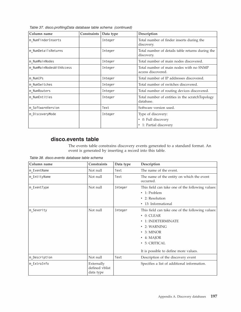
Table 37. disco.profilingData database table schema (continued)
Column name Constraints Data type Description
m_NumFinderInserts Integer Total number of finder inserts during thediscovery.
m_NumDetailsReturns Integer Total number of details table returns during thediscovery.
m_NumMainNodes Integer Total number of main nodes discovered.
m_NumMainNodesWithAccess Integer Total number of main nodes with no SNMPaccess discovered.
m_NumIPs Integer Total number of IP addresses discovered.
m_NumSwitches Integer Total number of switches discovered.
m_NumRouters Integer Total number of routing devices discovered.
m_NumEntities Integer Total number of entities in the scratchTopologydatabase.
m_SoftwareVersion Text Software version used.
m_DiscoveryMode Integer Type of discovery:
v 0: Full discovery
v 1: Partial discovery
disco.events tableThe events table constrains discovery events generated to a standard format. Anevent is generated by inserting a record into this table.
Table 38. disco.events database table schema
Column name Constraints Data type Description
m_EventName Not null Text The name of the event.
m_EntityName Not null Text The name of the entity on which the eventoccurred.
m_EventType Not null Integer This field can take one of the following values:
v 1: Problem
v 2: Resolution
v 13: Informational
m_Severity Not null Integer This field can take one of the following values:
v 0: CLEAR
v 1: INDETERMINATE
v 2: WARNING
v 3: MINOR
v 4: MAJOR
v 5: CRITICAL
It is possible to define more values.
m_Description Not null Text Description of the discovery event
m_ExtraInfo Externallydefined vblistdata type
Specifies a list of additional information.
Appendix A. Discovery databases 197

Related concepts:“Process flow for creating discovery events” on page 164Discovery events are created during the discovery process showing the progress ofagents, stitchers, and finders. These events are sent to and stored in TivoliNetcool/OMNIbus and can be viewed using the Web GUI.
disco.ipCustomTags tableThe ipCustomTags table stores custom tags, which can be associated with uniquediscovered entities during the discovery and used to perform custom visualizationand polling tasks.
Table 39. disco.ipCustomTags database table schema
Column name Constraints Data type Description
m_UniqueAddress Not null Text IP address to which the name-value pair tagsin the m_CustomTags is to be associated to.
m_StitcherTagName Not null Text Name of a tag to be evaluated using theGetTagStitcher.stch stitcher.
m_CustomTags Not null Object typevblist
List of name-value pair tags.
Related tasks:“Adding tags to entities using custom tag tables” on page 173You can add name-value pair tags to entities by creating inserts containing thename-value pair data into the disco.ipCustomTags table or into thedisco.filterCustomTags table.
disco.filterCustomTags tableThe filterCustomTags table stores custom tags, which can be associated with afiltered set of discovered entities during the discovery and used to perform customvisualization and polling tasks.
Table 40. disco.filterCustomTags database table schema
Column name Constraints Data type Description
m_Filter Not null Text Filter definition that extracts a set of IPaddress to which the name-value pair tags inthe m_CustomTags is to be associated to. Youcan create a filter based on any attributesassociated with discovered entities. Forexample, you could apply the following filters:
v Filter based on entity IP address:"m_UniqueAddress LIKE ’172.20.3’"
v Filter based on entity name: "m_Name LIKE’lon’"
v Filter based on VLAN identifier of a VLANentity: "m_LocalNbr->m_VlanID = 102"
m_StitcherTagName Not null Text Name of a tag to be evaluated using theGetTagStitcher.stch stitcher.
m_CustomTags Not null Object typevblist
List of name-value pair tags.
198 IBM Tivoli Network Manager IP Edition: Discovery Guide
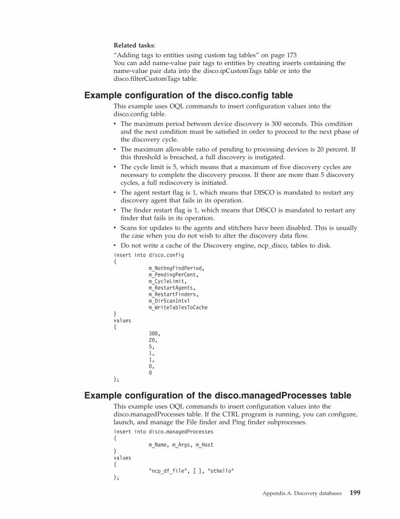
Related tasks:“Adding tags to entities using custom tag tables” on page 173You can add name-value pair tags to entities by creating inserts containing thename-value pair data into the disco.ipCustomTags table or into thedisco.filterCustomTags table.
Example configuration of the disco.config tableThis example uses OQL commands to insert configuration values into thedisco.config table.v The maximum period between device discovery is 300 seconds. This condition
and the next condition must be satisfied in order to proceed to the next phase ofthe discovery cycle.
v The maximum allowable ratio of pending to processing devices is 20 percent. Ifthis threshold is breached, a full discovery is instigated.
v The cycle limit is 5, which means that a maximum of five discovery cycles arenecessary to complete the discovery process. If there are more than 5 discoverycycles, a full rediscovery is initiated.
v The agent restart flag is 1, which means that DISCO is mandated to restart anydiscovery agent that fails in its operation.
v The finder restart flag is 1, which means that DISCO is mandated to restart anyfinder that fails in its operation.
v Scans for updates to the agents and stitchers have been disabled. This is usuallythe case when you do not wish to alter the discovery data flow.
v Do not write a cache of the Discovery engine, ncp_disco, tables to disk.insert into disco.config(
m_NothngFindPeriod,m_PendingPerCent,m_CycleLimit,m_RestartAgents,m_RestartFinders,m_DirScanIntvlm_WriteTablesToCache
)values(
300,20,5,1,1,0,0
);
Example configuration of the disco.managedProcesses tableThis example uses OQL commands to insert configuration values into thedisco.managedProcesses table. If the CTRL program is running, you can configure,launch, and manage the File finder and Ping finder subprocesses.insert into disco.managedProcesses(
m_Name, m_Args, m_Host)values(
"ncp_df_file", [ ], "othello");
Appendix A. Discovery databases 199
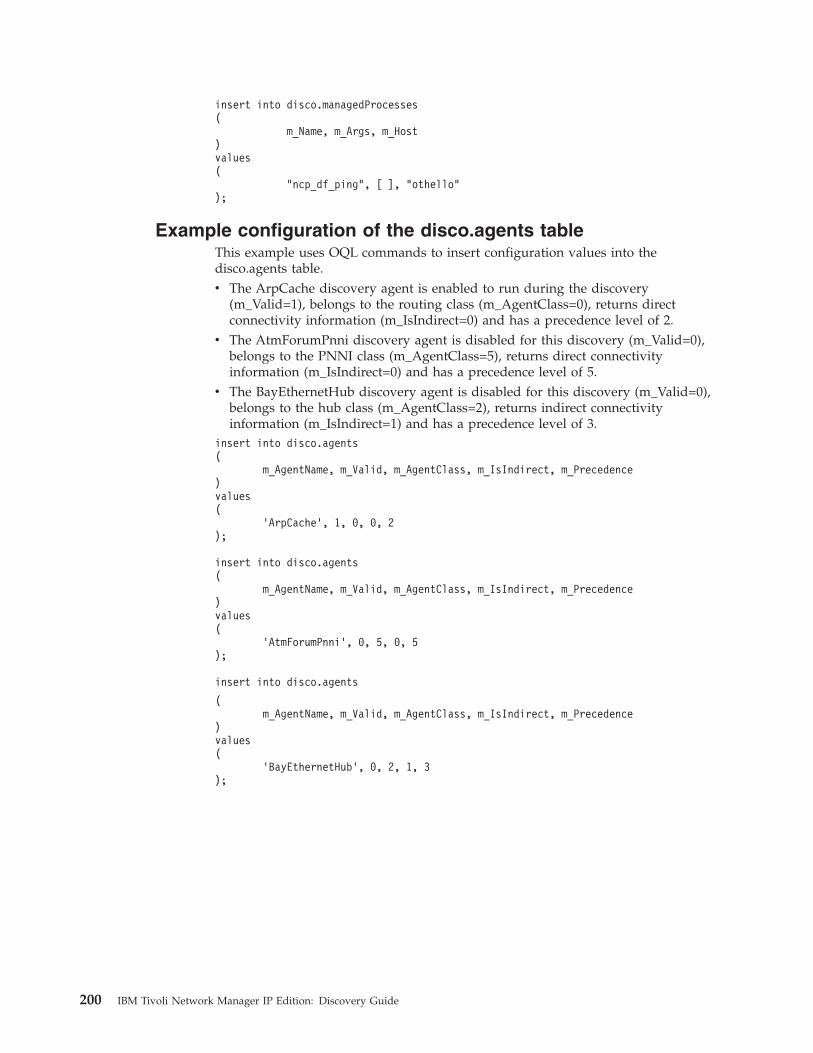
insert into disco.managedProcesses(
m_Name, m_Args, m_Host)values(
"ncp_df_ping", [ ], "othello");
Example configuration of the disco.agents tableThis example uses OQL commands to insert configuration values into thedisco.agents table.v The ArpCache discovery agent is enabled to run during the discovery
(m_Valid=1), belongs to the routing class (m_AgentClass=0), returns directconnectivity information (m_IsIndirect=0) and has a precedence level of 2.
v The AtmForumPnni discovery agent is disabled for this discovery (m_Valid=0),belongs to the PNNI class (m_AgentClass=5), returns direct connectivityinformation (m_IsIndirect=0) and has a precedence level of 5.
v The BayEthernetHub discovery agent is disabled for this discovery (m_Valid=0),belongs to the hub class (m_AgentClass=2), returns indirect connectivityinformation (m_IsIndirect=1) and has a precedence level of 3.
insert into disco.agents(
m_AgentName, m_Valid, m_AgentClass, m_IsIndirect, m_Precedence)values(
’ArpCache’, 1, 0, 0, 2);
insert into disco.agents(
m_AgentName, m_Valid, m_AgentClass, m_IsIndirect, m_Precedence)values(
’AtmForumPnni’, 0, 5, 0, 5);
insert into disco.agents
(m_AgentName, m_Valid, m_AgentClass, m_IsIndirect, m_Precedence
)values(
’BayEthernetHub’, 0, 2, 1, 3);
200 IBM Tivoli Network Manager IP Edition: Discovery Guide
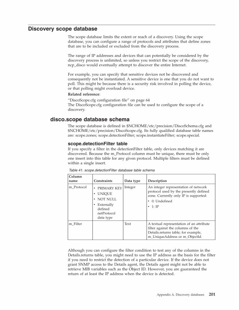
Discovery scope databaseThe scope database limits the extent or reach of a discovery. Using the scopedatabase, you can configure a range of protocols and attributes that define zonesthat are to be included or excluded from the discovery process.
The range of IP addresses and devices that can potentially be considered by thediscovery process is unlimited, so unless you restrict the scope of the discovery,ncp_disco would eventually attempt to discover the entire Internet.
For example, you can specify that sensitive devices not be discovered andconsequently not be instantiated. A sensitive device is one that you do not want topoll. This might be because there is a security risk involved in polling the device,or that polling might overload device.Related reference:“DiscoScope.cfg configuration file” on page 64The DiscoScope.cfg configuration file can be used to configure the scope of adiscovery.
disco.scope database schemaThe scope database is defined in $NCHOME/etc/precision/DiscoSchema.cfg and$NCHOME/etc/precision/DiscoScope.cfg. Its fully qualified database table namesare: scope.zones; scope.detectionFilter; scope.instantiateFilter; scope.special.
scope.detectionFilter tableIf you specify a filter in the detectionFilter table, only devices matching it arediscovered. Because the m_Protocol column must be unique, there must be onlyone insert into this table for any given protocol. Multiple filters must be definedwithin a single insert.
Table 41. scope.detectionFilter database table schema
Columnname Constraints Data type Description
m_Protocol v PRIMARY KEY
v UNIQUE
v NOT NULL
v ExternallydefinednetProtocoldata type
Integer An integer representation of networkprotocol used by the presently definedzone. Currently only IP is supported:
v 0: Undefined
v 1: IP
m_Filter Text A textual representation of an attributefilter against the columns of theDetails.returns table; for example,m_UniqueAddress or m_ObjectId.
Although you can configure the filter condition to test any of the columns in theDetails.returns table, you might need to use the IP address as the basis for the filterif you need to restrict the detection of a particular device. If the device does notgrant SNMP access to the Details agent, the Details agent might not be able toretrieve MIB variables such as the Object ID. However, you are guaranteed thereturn of at least the IP address when the device is detected.
Appendix A. Discovery databases 201
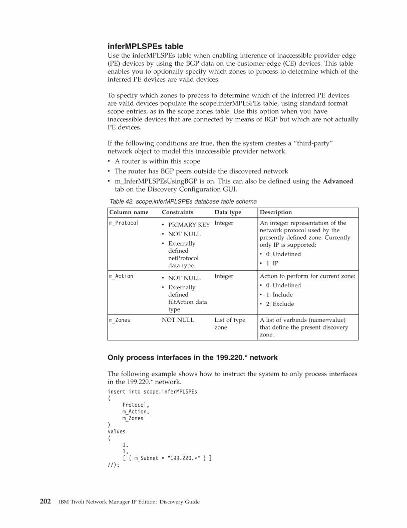
inferMPLSPEs tableUse the inferMPLSPEs table when enabling inference of inaccessible provider-edge(PE) devices by using the BGP data on the customer-edge (CE) devices. This tableenables you to optionally specify which zones to process to determine which of theinferred PE devices are valid devices.
To specify which zones to process to determine which of the inferred PE devicesare valid devices populate the scope.inferMPLSPEs table, using standard formatscope entries, as in the scope.zones table. Use this option when you haveinaccessible devices that are connected by means of BGP but which are not actuallyPE devices.
If the following conditions are true, then the system creates a “third-party”network object to model this inaccessible provider network.v A router is within this scopev The router has BGP peers outside the discovered networkv m_InferMPLSPEsUsingBGP is on. This can also be defined using the Advanced
tab on the Discovery Configuration GUI.
Table 42. scope.inferMPLSPEs database table schema
Column name Constraints Data type Description
m_Protocol v PRIMARY KEY
v NOT NULL
v ExternallydefinednetProtocoldata type
Integer An integer representation of thenetwork protocol used by thepresently defined zone. Currentlyonly IP is supported:
v 0: Undefined
v 1: IP
m_Action v NOT NULL
v ExternallydefinedfiltAction datatype
Integer Action to perform for current zone:
v 0: Undefined
v 1: Include
v 2: Exclude
m_Zones NOT NULL List of typezone
A list of varbinds (name=value)that define the present discoveryzone.
Only process interfaces in the 199.220.* network
The following example shows how to instruct the system to only process interfacesin the 199.220.* network.insert into scope.inferMPLSPEs(
Protocol,m_Action,m_Zones
)values(
1,1,[ { m_Subnet = "199.220.*" } ]
//);
202 IBM Tivoli Network Manager IP Edition: Discovery Guide
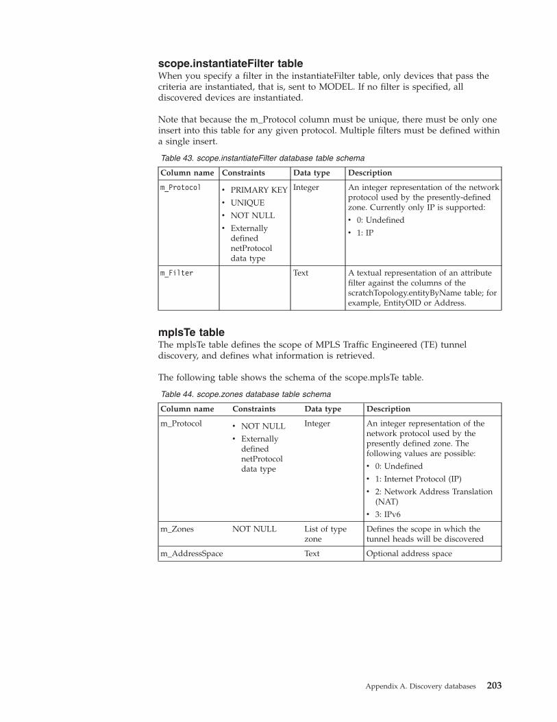
scope.instantiateFilter tableWhen you specify a filter in the instantiateFilter table, only devices that pass thecriteria are instantiated, that is, sent to MODEL. If no filter is specified, alldiscovered devices are instantiated.
Note that because the m_Protocol column must be unique, there must be only oneinsert into this table for any given protocol. Multiple filters must be defined withina single insert.
Table 43. scope.instantiateFilter database table schema
Column name Constraints Data type Description
m_Protocol v PRIMARY KEY
v UNIQUE
v NOT NULL
v ExternallydefinednetProtocoldata type
Integer An integer representation of the networkprotocol used by the presently-definedzone. Currently only IP is supported:
v 0: Undefined
v 1: IP
m_Filter Text A textual representation of an attributefilter against the columns of thescratchTopology.entityByName table; forexample, EntityOID or Address.
mplsTe tableThe mplsTe table defines the scope of MPLS Traffic Engineered (TE) tunneldiscovery, and defines what information is retrieved.
The following table shows the schema of the scope.mplsTe table.
Table 44. scope.zones database table schema
Column name Constraints Data type Description
m_Protocol v NOT NULL
v ExternallydefinednetProtocoldata type
Integer An integer representation of thenetwork protocol used by thepresently defined zone. Thefollowing values are possible:
v 0: Undefined
v 1: Internet Protocol (IP)
v 2: Network Address Translation(NAT)
v 3: IPv6
m_Zones NOT NULL List of typezone
Defines the scope in which thetunnel heads will be discovered
m_AddressSpace Text Optional address space
Appendix A. Discovery databases 203
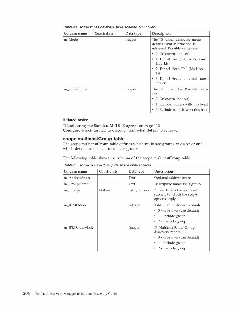
Table 44. scope.zones database table schema (continued)
Column name Constraints Data type Description
m_Mode Integer The TE tunnel discovery modedefines what information isretrieved. Possible values are:
v 0: Unknown (not set)
v 1: Tunnel Head/Tail with TransitHop List
v 2: Tunnel Head/Tail (No HopList)
v 3: Tunnel Head, Tails, and Transitdevices
m_TunnelFilter Integer The TE tunnel filter. Possible valuesare:
v 0: Unknown (not set)
v 1: Include tunnels with this head
v 2: Exclude tunnels with this head
Related tasks:“Configuring the StandardMPLSTE agent” on page 112Configure which tunnels to discover, and what details to retrieve.
scope.multicastGroup tableThe scope.multicastGroup table defines which multicast groups to discover andwhich details to retrieve from these groups.
The following table shows the schema of the scope.multicastGroup table.
Table 45. scope.multicastGroup database table schema
Column name Constraints Data type Description
m_AddressSpace Text Optional address space
m_GroupName Text Descriptive name for a group
m_Groups Not null list type zone Zones defines the multicastsubnets to which the scopeoptions apply
m_IGMPMode Integer IGMP Group discovery mode
v 0 - unknown (use default)
v 1 - Include group
v 2 - Exclude group
m_IPMRouteMode Integer IP Multicast Route Groupdiscovery mode:
v 0 - unknown (use default)
v 1 - Include group
v 2 - Exclude group
204 IBM Tivoli Network Manager IP Edition: Discovery Guide
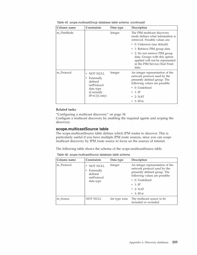
Table 45. scope.multicastGroup database table schema (continued)
Column name Constraints Data type Description
m_PimMode Integer The PIM multicast discoverymode defines what information isretrieved. Possible values are:
v 0: Unknown (use default)
v 1: Retrieve PIM group data
v 2: Do not retrieve PIM groupdata. Groups with this optionapplied will not be representedin the PIM Service/End Pointdata.
m_Protocol v NOT NULL
v ExternallydefinednetProtocoldata type(CurrentlyIPv4 [1] only)
Integer An integer representation of thenetwork protocol used by thepresently defined group. Thefollowing values are possible:
v 0: Undefined
v 1: IP
v 2: NAT
v 3: IPv6
Related tasks:“Configuring a multicast discovery” on page 34Configure a multicast discovery by enabling the required agents and scoping thediscovery.
scope.multicastSource tableThe scope.multicastSource table defines which IPM routes to discover. This isparticularly useful if you have multiple IPM route sources, since you can scopemulticast discovery by IPM route source to focus on the sources of interest.
The following table shows the schema of the scope.multicastSource table.
Table 46. scope.multicastSource database table schema
Column name Constraints Data type Description
m_Protocol v NOT NULL
v ExternallydefinednetProtocoldata type
Integer An integer representation of thenetwork protocol used by thepresently defined group. Thefollowing values are possible:
v 0: Undefined
v 1: IP
v 2: NAT
v 3: IPv6
m_Source NOT NULL list type zone The multicast source to beincluded or excluded
Appendix A. Discovery databases 205
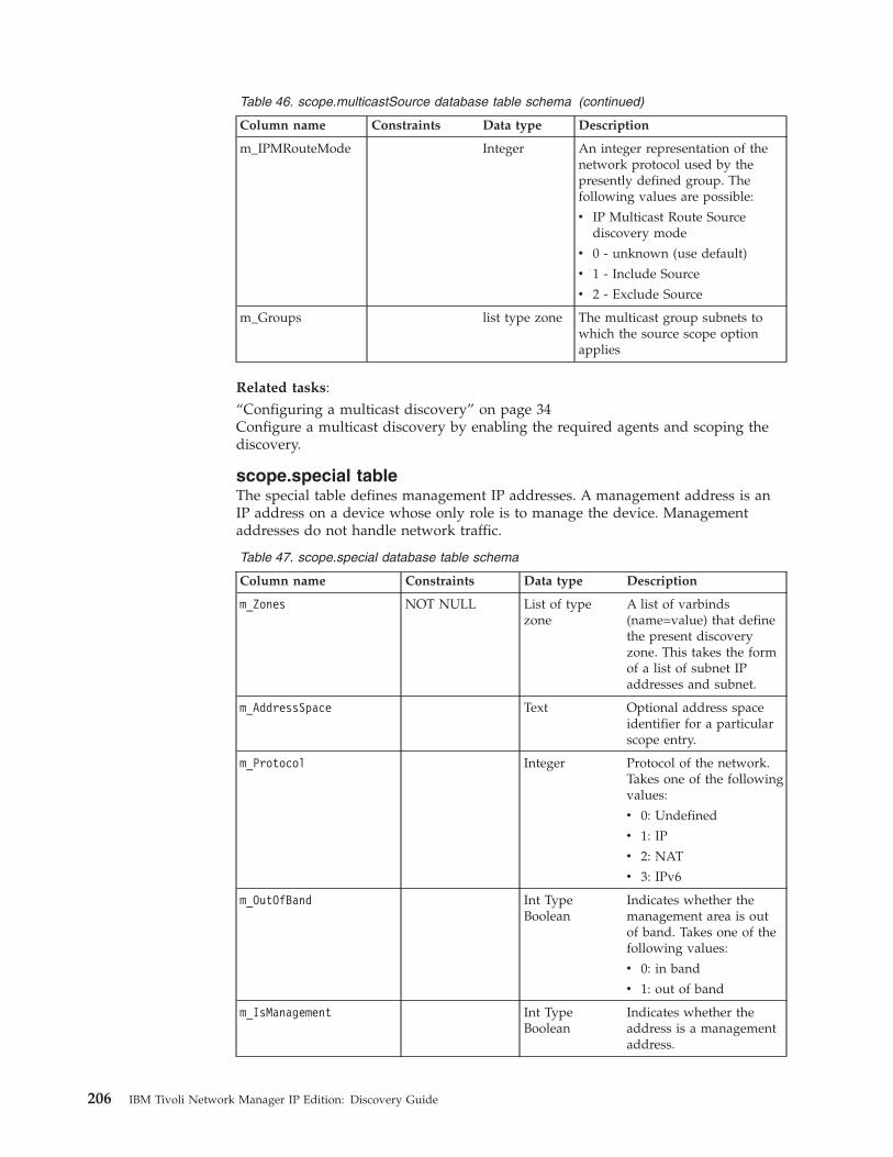
Table 46. scope.multicastSource database table schema (continued)
Column name Constraints Data type Description
m_IPMRouteMode Integer An integer representation of thenetwork protocol used by thepresently defined group. Thefollowing values are possible:
v IP Multicast Route Sourcediscovery mode
v 0 - unknown (use default)
v 1 - Include Source
v 2 - Exclude Source
m_Groups list type zone The multicast group subnets towhich the source scope optionapplies
Related tasks:“Configuring a multicast discovery” on page 34Configure a multicast discovery by enabling the required agents and scoping thediscovery.
scope.special tableThe special table defines management IP addresses. A management address is anIP address on a device whose only role is to manage the device. Managementaddresses do not handle network traffic.
Table 47. scope.special database table schema
Column name Constraints Data type Description
m_Zones NOT NULL List of typezone
A list of varbinds(name=value) that definethe present discoveryzone. This takes the formof a list of subnet IPaddresses and subnet.
m_AddressSpace Text Optional address spaceidentifier for a particularscope entry.
m_Protocol Integer Protocol of the network.Takes one of the followingvalues:
v 0: Undefined
v 1: IP
v 2: NAT
v 3: IPv6
m_OutOfBand Int TypeBoolean
Indicates whether themanagement area is outof band. Takes one of thefollowing values:
v 0: in band
v 1: out of band
m_IsManagement Int TypeBoolean
Indicates whether theaddress is a managementaddress.
206 IBM Tivoli Network Manager IP Edition: Discovery Guide
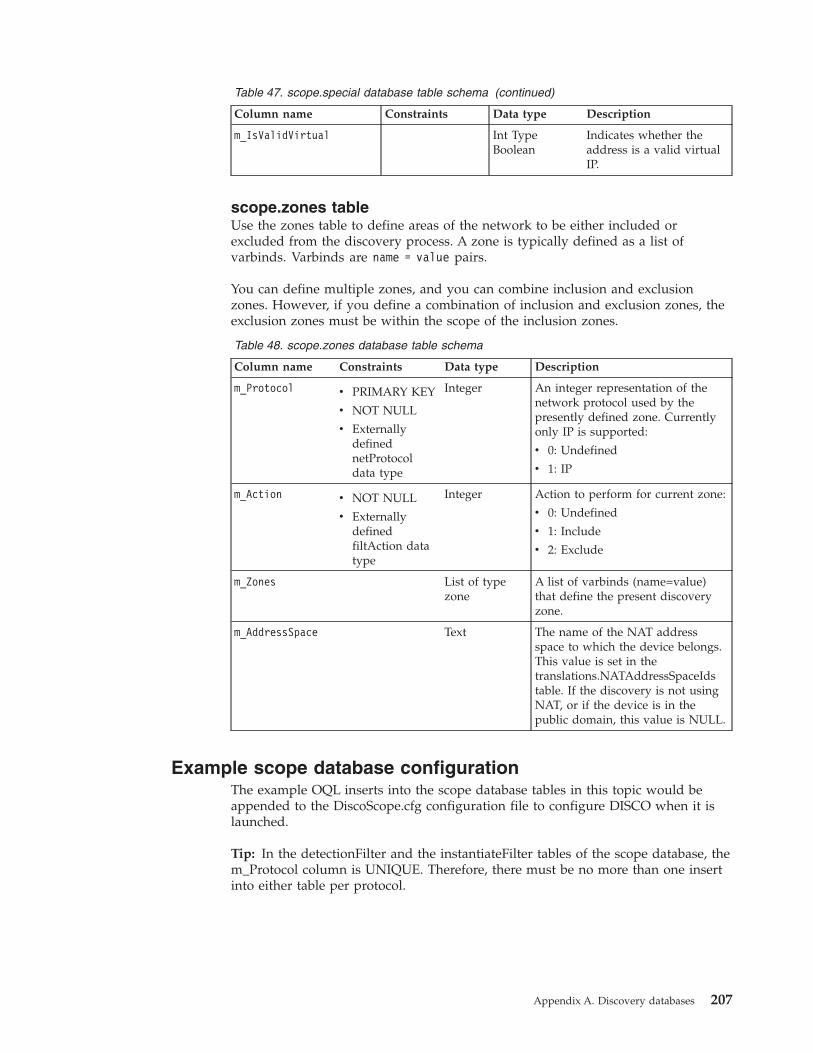
Table 47. scope.special database table schema (continued)
Column name Constraints Data type Description
m_IsValidVirtual Int TypeBoolean
Indicates whether theaddress is a valid virtualIP.
scope.zones tableUse the zones table to define areas of the network to be either included orexcluded from the discovery process. A zone is typically defined as a list ofvarbinds. Varbinds are name = value pairs.
You can define multiple zones, and you can combine inclusion and exclusionzones. However, if you define a combination of inclusion and exclusion zones, theexclusion zones must be within the scope of the inclusion zones.
Table 48. scope.zones database table schema
Column name Constraints Data type Description
m_Protocol v PRIMARY KEY
v NOT NULL
v ExternallydefinednetProtocoldata type
Integer An integer representation of thenetwork protocol used by thepresently defined zone. Currentlyonly IP is supported:
v 0: Undefined
v 1: IP
m_Action v NOT NULL
v ExternallydefinedfiltAction datatype
Integer Action to perform for current zone:
v 0: Undefined
v 1: Include
v 2: Exclude
m_Zones List of typezone
A list of varbinds (name=value)that define the present discoveryzone.
m_AddressSpace Text The name of the NAT addressspace to which the device belongs.This value is set in thetranslations.NATAddressSpaceIdstable. If the discovery is not usingNAT, or if the device is in thepublic domain, this value is NULL.
Example scope database configurationThe example OQL inserts into the scope database tables in this topic would beappended to the DiscoScope.cfg configuration file to configure DISCO when it islaunched.
Tip: In the detectionFilter and the instantiateFilter tables of the scope database, them_Protocol column is UNIQUE. Therefore, there must be no more than one insertinto either table per protocol.
Appendix A. Discovery databases 207

Configuration of the scope.zones tableUse this information to understand how to configure the scope.zones table.
Creating two inclusion zones
This example configuration of the scope.zones table creates two inclusion zones forthe current discovery. Both zones are defined using a single insert.insert into scope.zones(
m_Protocol,m_Action,m_Zones
)values(
1,1,[
{m_Subnet="172.16.1.0"m_NetMask=24
},{
m_Subnet="172.16.2.*"}
]);
The previous OQL insert specifies the following conditions:v The network uses the Internet Protocol (m_Protocol=1).v Any devices that fall into the present zone are to be included in the discovery
(m_Action=1).v The discovery includes:
– Any device that falls within the 172.16.1.0 subnet (with a subnet mask of 24,that is, 24 bits turned on and 8 bits turned off, which implies a netmask of255.255.255.0).
– Any device with an IP address starting with 172.16.2, that is, in the 172.16.2.0subnet with a mask of 255.255.255.0.
Creating a zone within a zone
Zones can be specified within zones: within a given inclusion zone, you canspecify devices or subnets that are not to be detected. These devices are not pingedby the Ping finder or interrogated by the discovery agents. For example, you candefine an include scope zone consisting of the Class B subnet 172.20.0.0/16, andcompletely contained within that zone you can specify an exclude scope zoneconsisting of the subnet 172.20.32.0/19. Finally, completely contained within theexclude scope zone you could specify an include scope zone 172.20.33.0/24.// Include all IP addresses in this rangeinsert into scope.zones(
m_Protocol,m_Action,m_Zones
)values(
1,1,
208 IBM Tivoli Network Manager IP Edition: Discovery Guide

[{m_Subnet = ’172.20.0.0’, m_NetMask = 16 }]);
// Apart from the IP addresses in this rangeinsert into scope.zones(
m_Protocol,m_Action,m_Zones
)values(
1,2,[{m_Subnet = ’172.20.32.0’ , m_NetMask = 19 }]
);// Except for these IP addresses which we do want to includeinsert into scope.zones(
m_Protocol,m_Action,m_Zones
)values(
1,1,[{m_Subnet = ’172.20.33.0’ , m_NetMask = 24 }]
);
The previous OQL insert specifies three scope zones:v All zones specify that the network uses the Internet Protocol (m_Protocol=1).v Include and exclude zones are defined as follows:
– Any devices that fall into the first zone, 172.20.0.0/16, are to be included inthe discovery (m_Action=1).
– Any devices that fall into the second zone, 172.20.32.0/19, which iscompletely contained within the first zone, are to be excluded from thediscovery (m_Action=2).
– Any devices that fall into the third zone, 172.20.33.0/24, which is completelycontained within the second zone, are to be included in the discovery(m_Action=1).
Preventing the detection of devices with a filterThis example insert defines a detection filter. Since there must only be one insertinto the scope.detectionFilter table, multiple conditions for IP must be definedusing a single insert. The conditions of the filter can be combined using theBoolean OQL keywords AND and OR.insert into scope.detectionFilter(
m_Protocol, m_Filter)values(
1,"(
( m_UniqueAddress <> ’10.10.63.234’ )AND( m_ObjectId not like ’1\.3\.6\.1\.4\.1\..*’ )
)");
Appendix A. Discovery databases 209
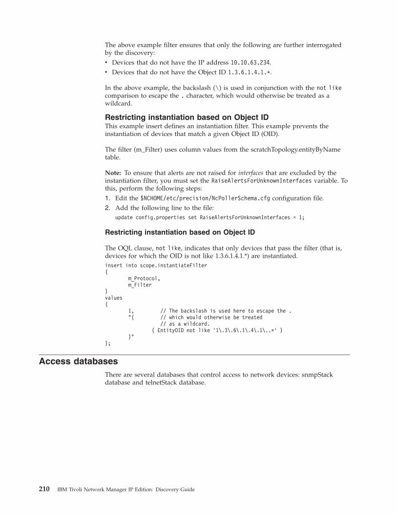
The above example filter ensures that only the following are further interrogatedby the discovery:v Devices that do not have the IP address 10.10.63.234.v Devices that do not have the Object ID 1.3.6.1.4.1.*.
In the above example, the backslash (\) is used in conjunction with the not likecomparison to escape the . character, which would otherwise be treated as awildcard.
Restricting instantiation based on Object IDThis example insert defines an instantiation filter. This example prevents theinstantiation of devices that match a given Object ID (OID).
The filter (m_Filter) uses column values from the scratchTopology.entityByNametable.
Note: To ensure that alerts are not raised for interfaces that are excluded by theinstantiation filter, you must set the RaiseAlertsForUnknownInterfaces variable. Tothis, perform the following steps:1. Edit the $NCHOME/etc/precision/NcPollerSchema.cfg configuration file.2. Add the following line to the file:
update config.properties set RaiseAlertsForUnknownInterfaces = 1;
Restricting instantiation based on Object ID
The OQL clause, not like, indicates that only devices that pass the filter (that is,devices for which the OID is not like 1.3.6.1.4.1.*) are instantiated.insert into scope.instantiateFilter(
m_Protocol,m_Filter
)values(
1, // The backslash is used here to escape the ."( // which would otherwise be treated
// as a wildcard.( EntityOID not like ’1\.3\.6\.1\.4\.1\..*’ )
)");
Access databasesThere are several databases that control access to network devices: snmpStackdatabase and telnetStack database.
210 IBM Tivoli Network Manager IP Edition: Discovery Guide
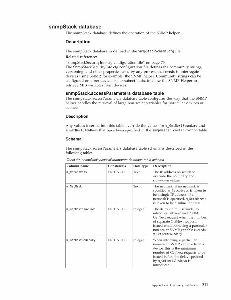
snmpStack databaseThe snmpStack database defines the operation of the SNMP helper.
Description
The snmpStack database in defined in the SnmpStackSchema.cfg file.Related reference:“SnmpStackSecurityInfo.cfg configuration file” on page 75The SnmpStackSecurityInfo.cfg configuration file defines the community strings,versioning, and other properties used by any process that needs to interrogatedevices using SNMP, for example, the SNMP helper. Community strings can beconfigured on a per-device or per-subnet basis, to allow the SNMP Helper toretrieve MIB variables from devices.
snmpStack.accessParameters database tableThe snmpStack.accessParameters database table configures the way that the SNMPhelper handles the retrieval of large non-scalar variables for particular devices orsubnets.
Description
Any values inserted into this table override the values for m_GetNextBoundary andm_GetNextSlowDown that have been specified in the snmpHelper.configuration table.
Schema
The snmpStack.accessParameters database table schema is described in thefollowing table:
Table 49. snmpStack.accessParameters database table schema
Column name Constraints Data type Description
m_NetAddress NOT NULL Text The IP address on which tooverride the boundary andslowdown values.
m_NetMask Text The netmask. If no netmask isspecified, m_NetAddress is taken tobe a single IP address. If anetmask is specified, m_NetAddressis taken to be a subnet address.
m_GetNextSlowDown NOT NULL Integer The delay (in milliseconds) tointroduce between each SNMPGetNext request when the numberof separate GetNext requestsissued while retrieving a particularnon-scalar SNMP variable exceedsm_GetNextBoundary.
m_GetNextBoundary NOT NULL Integer When retrieving a particularnon-scalar SNMP variable from adevice, this is the minimumnumber of GetNext requests to beissued before the delay specifiedby m_GetNextSlowDown isintroduced.
Appendix A. Discovery databases 211
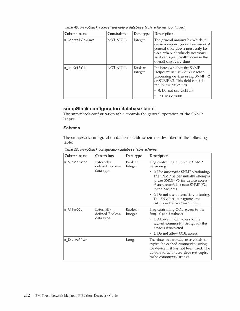
Table 49. snmpStack.accessParameters database table schema (continued)
Column name Constraints Data type Description
m_GeneralSlowDown NOT NULL Integer The general amount by which todelay a request (in milliseconds). Ageneral slow down must only beused where absolutely necessaryas it can significantly increase theoverall discovery time.
m_useGetBulk NOT NULL BooleanInteger
Indicates whether the SNMPHelper must use GetBulk whenprocessing devices using SNMP v2or SNMP v3. This field can takethe following values:
v 0: Do not use GetBulk
v 1: Use GetBulk
snmpStack.configuration database tableThe snmpStack.configuration table controls the general operation of the SNMPhelper.
Schema
The snmpStack.configuration database table schema is described in the followingtable:
Table 50. snmpStack.configuration database table schema
Column name Constraints Data type Description
m_AutoVersion Externallydefined Booleandata type
BooleanInteger
Flag controlling automatic SNMPversioning:
v 1: Use automatic SNMP versioning.The SNMP helper initially attemptsto use SNMP V3 for device access;if unsuccessful, it uses SNMP V2,then SNMP V1.
v 0: Do not use automatic versioning.The SNMP helper ignores theentries in the versions table.
m_AllowOQL Externallydefined Booleandata type
BooleanInteger
Flag controlling OQL access to theSnmpHelper database:
v 1: Allowed OQL access to thecached community strings for thedevices discovered.
v 2: Do not allow OQL access.
m_ExpireAfter Long The time, in seconds, after which toexpire the cached community stringfor device if it has not been used. Thedefault value of zero does not expirecache community strings.
212 IBM Tivoli Network Manager IP Edition: Discovery Guide
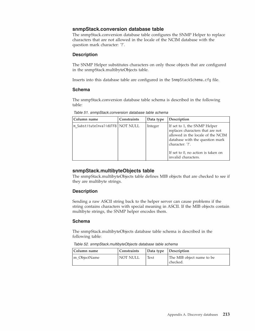
snmpStack.conversion database tableThe snmpStack.conversion database table configures the SNMP Helper to replacecharacters that are not allowed in the locale of the NCIM database with thequestion mark character: '?'.
Description
The SNMP Helper substitutes characters on only those objects that are configuredin the snmpStack.multibyteObjects table.
Inserts into this database table are configured in the SnmpStackSchema.cfg file.
Schema
The snmpStack.conversion database table schema is described in the followingtable:
Table 51. snmpStack.conversion database table schema
Column name Constraints Data type Description
m_SubstituteInvalidUTF8 NOT NULL Integer If set to 1, the SNMP Helperreplaces characters that are notallowed in the locale of the NCIMdatabase with the question markcharacter: '?'.
If set to 0, no action is taken oninvalid characters.
snmpStack.multibyteObjects tableThe snmpStack.multibyteObjects table defines MIB objects that are checked to see ifthey are multibyte strings.
Description
Sending a raw ASCII string back to the helper server can cause problems if thestring contains characters with special meaning in ASCII. If the MIB objects containmultibyte strings, the SNMP helper encodes them.
Schema
The snmpStack.multibyteObjects database table schema is described in thefollowing table:
Table 52. snmpStack.multibyteObjects database table schema
Column name Constraints Data type Description
m_ObjectName NOT NULL Text The MIB object name to bechecked.
Appendix A. Discovery databases 213
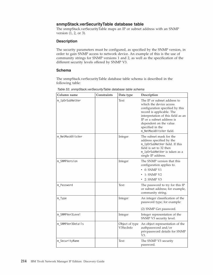
snmpStack.verSecurityTable database tableThe snmpStack.verSecurityTable maps an IP or subnet address with an SNMPversion (1, 2, or 3).
Description
The security parameters must be configured, as specified by the SNMP version, inorder to gain SNMP access to network device. An example of this is the use ofcommunity strings for SNMP versions 1 and 2, as well as the specification of thedifferent security levels offered by SNMP V3.
Schema
The snmpStack.verSecurityTable database table schema is described in thefollowing table:
Table 53. snmpStack.verSecurityTable database table schema
Column name Constraints Data type Description
m_IpOrSubNetVer Text The IP or subnet address towhich the device accessconfiguration specified by thisrecord is applicable. Theinterpretation of this field as anIP or a subnet address isdependent on the valuespecified in them_NetMaskBitsVer field.
m_NetMaskBitsVer Integer The subnet mask for theaddress specified by them_IpOrSubNetVer field. If thisfield is set to 32 thenm_IpOrSubNetVer is taken as asingle IP address.
m_SNMPVersion Integer The SNMP version that thisconfiguration applies to.
v 0: SNMP V1
v 1: SNMP V2
v 2: SNMP V3
m_Password Text The password to try for this IPor subnet address; for example,community string.
m_Type Integer An integer classification of thepassword type; for example:
(2) SNMP Get password.
m_SNMPVer3Level Integer Integer representation of theSNMP V3 security level.
m_SNMPVer3Details Object of typeV3SecInfo
An object representation of theauthpassword and/orprivpassword details for SNMPV3.
m_SecurityName Text The SNMP V3 securitypassword.
214 IBM Tivoli Network Manager IP Edition: Discovery Guide
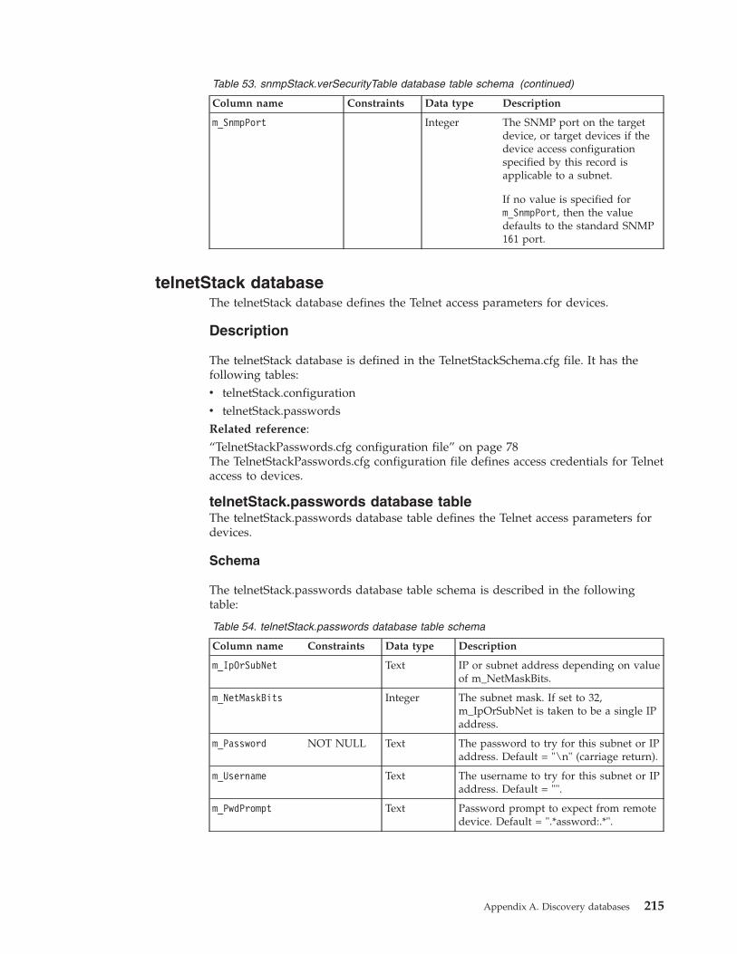
Table 53. snmpStack.verSecurityTable database table schema (continued)
Column name Constraints Data type Description
m_SnmpPort Integer The SNMP port on the targetdevice, or target devices if thedevice access configurationspecified by this record isapplicable to a subnet.
If no value is specified form_SnmpPort, then the valuedefaults to the standard SNMP161 port.
telnetStack databaseThe telnetStack database defines the Telnet access parameters for devices.
Description
The telnetStack database is defined in the TelnetStackSchema.cfg file. It has thefollowing tables:v telnetStack.configurationv telnetStack.passwordsRelated reference:“TelnetStackPasswords.cfg configuration file” on page 78The TelnetStackPasswords.cfg configuration file defines access credentials for Telnetaccess to devices.
telnetStack.passwords database tableThe telnetStack.passwords database table defines the Telnet access parameters fordevices.
Schema
The telnetStack.passwords database table schema is described in the followingtable:
Table 54. telnetStack.passwords database table schema
Column name Constraints Data type Description
m_IpOrSubNet Text IP or subnet address depending on valueof m_NetMaskBits.
m_NetMaskBits Integer The subnet mask. If set to 32,m_IpOrSubNet is taken to be a single IPaddress.
m_Password NOT NULL Text The password to try for this subnet or IPaddress. Default = "\n" (carriage return).
m_Username Text The username to try for this subnet or IPaddress. Default = "".
m_PwdPrompt Text Password prompt to expect from remotedevice. Default = ".*assword:.*".
Appendix A. Discovery databases 215
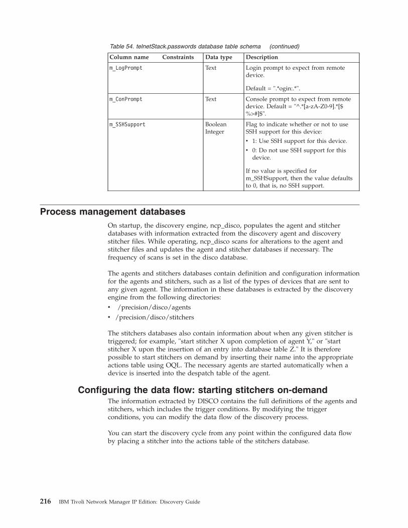
Table 54. telnetStack.passwords database table schema (continued)
Column name Constraints Data type Description
m_LogPrompt Text Login prompt to expect from remotedevice.
Default = ".*ogin:.*".
m_ConPrompt Text Console prompt to expect from remotedevice. Default = "^.*[a-zA-Z0-9].*[$%>#]$".
m_SSHSupport BooleanInteger
Flag to indicate whether or not to useSSH support for this device:
v 1: Use SSH support for this device.
v 0: Do not use SSH support for thisdevice.
If no value is specified form_SSHSupport, then the value defaultsto 0, that is, no SSH support.
Process management databasesOn startup, the discovery engine, ncp_disco, populates the agent and stitcherdatabases with information extracted from the discovery agent and discoverystitcher files. While operating, ncp_disco scans for alterations to the agent andstitcher files and updates the agent and stitcher databases if necessary. Thefrequency of scans is set in the disco database.
The agents and stitchers databases contain definition and configuration informationfor the agents and stitchers, such as a list of the types of devices that are sent toany given agent. The information in these databases is extracted by the discoveryengine from the following directories:v /precision/disco/agentsv /precision/disco/stitchers
The stitchers databases also contain information about when any given stitcher istriggered; for example, "start stitcher X upon completion of agent Y," or "startstitcher X upon the insertion of an entry into database table Z." It is thereforepossible to start stitchers on demand by inserting their name into the appropriateactions table using OQL. The necessary agents are started automatically when adevice is inserted into the despatch table of the agent.
Configuring the data flow: starting stitchers on-demandThe information extracted by DISCO contains the full definitions of the agents andstitchers, which includes the trigger conditions. By modifying the triggerconditions, you can modify the data flow of the discovery process.
You can start the discovery cycle from any point within the configured data flowby placing a stitcher into the actions table of the stitchers database.
216 IBM Tivoli Network Manager IP Edition: Discovery Guide
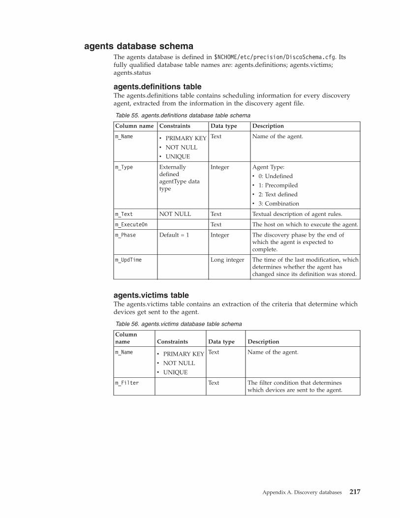
agents database schemaThe agents database is defined in $NCHOME/etc/precision/DiscoSchema.cfg. Itsfully qualified database table names are: agents.definitions; agents.victims;agents.status
agents.definitions tableThe agents.definitions table contains scheduling information for every discoveryagent, extracted from the information in the discovery agent file.
Table 55. agents.definitions database table schema
Column name Constraints Data type Description
m_Name v PRIMARY KEY
v NOT NULL
v UNIQUE
Text Name of the agent.
m_Type ExternallydefinedagentType datatype
Integer Agent Type:
v 0: Undefined
v 1: Precompiled
v 2: Text defined
v 3: Combination
m_Text NOT NULL Text Textual description of agent rules.
m_ExecuteOn Text The host on which to execute the agent.
m_Phase Default = 1 Integer The discovery phase by the end ofwhich the agent is expected tocomplete.
m_UpdTime Long integer The time of the last modification, whichdetermines whether the agent haschanged since its definition was stored.
agents.victims tableThe agents.victims table contains an extraction of the criteria that determine whichdevices get sent to the agent.
Table 56. agents.victims database table schema
Columnname Constraints Data type Description
m_Name v PRIMARY KEY
v NOT NULL
v UNIQUE
Text Name of the agent.
m_Filter Text The filter condition that determineswhich devices are sent to the agent.
Appendix A. Discovery databases 217
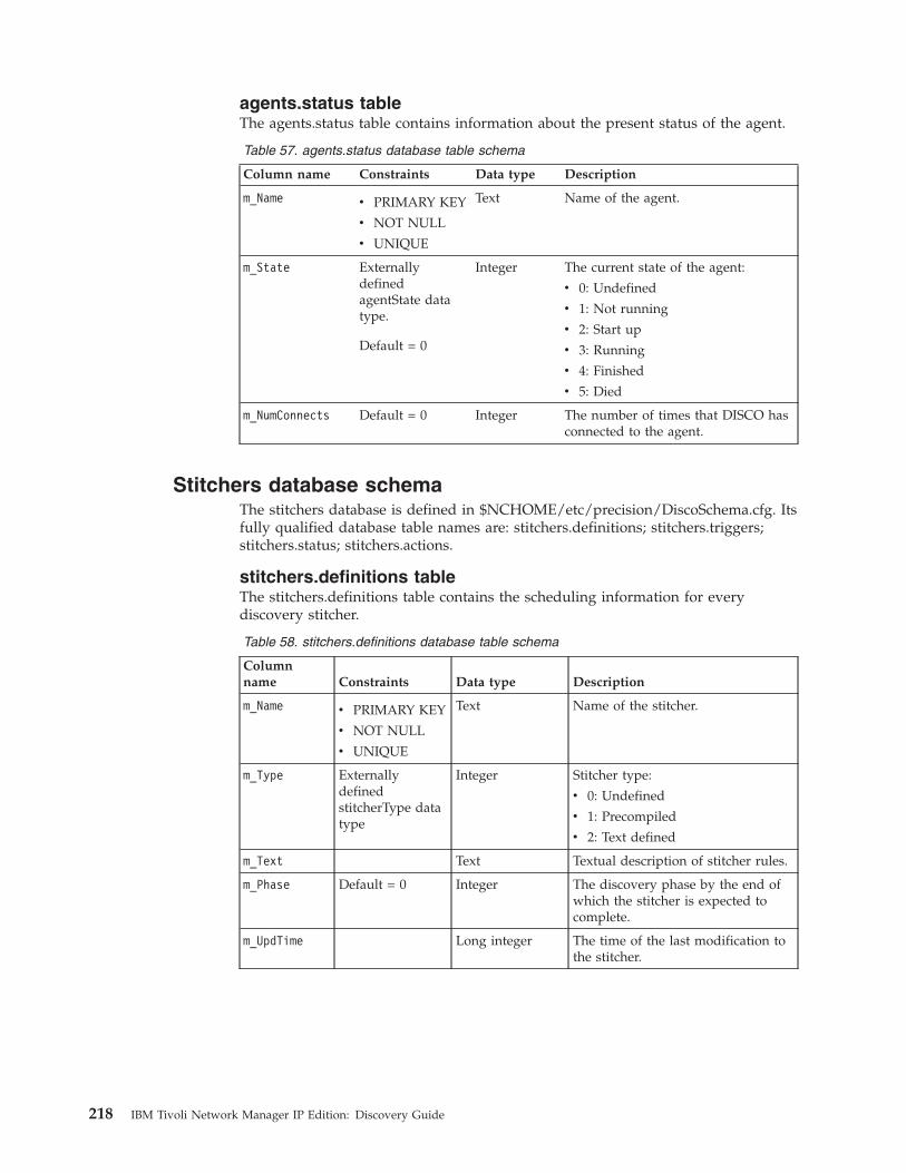
agents.status tableThe agents.status table contains information about the present status of the agent.
Table 57. agents.status database table schema
Column name Constraints Data type Description
m_Name v PRIMARY KEY
v NOT NULL
v UNIQUE
Text Name of the agent.
m_State ExternallydefinedagentState datatype.
Default = 0
Integer The current state of the agent:
v 0: Undefined
v 1: Not running
v 2: Start up
v 3: Running
v 4: Finished
v 5: Died
m_NumConnects Default = 0 Integer The number of times that DISCO hasconnected to the agent.
Stitchers database schemaThe stitchers database is defined in $NCHOME/etc/precision/DiscoSchema.cfg. Itsfully qualified database table names are: stitchers.definitions; stitchers.triggers;stitchers.status; stitchers.actions.
stitchers.definitions tableThe stitchers.definitions table contains the scheduling information for everydiscovery stitcher.
Table 58. stitchers.definitions database table schema
Columnname Constraints Data type Description
m_Name v PRIMARY KEY
v NOT NULL
v UNIQUE
Text Name of the stitcher.
m_Type ExternallydefinedstitcherType datatype
Integer Stitcher type:
v 0: Undefined
v 1: Precompiled
v 2: Text defined
m_Text Text Textual description of stitcher rules.
m_Phase Default = 0 Integer The discovery phase by the end ofwhich the stitcher is expected tocomplete.
m_UpdTime Long integer The time of the last modification tothe stitcher.
218 IBM Tivoli Network Manager IP Edition: Discovery Guide
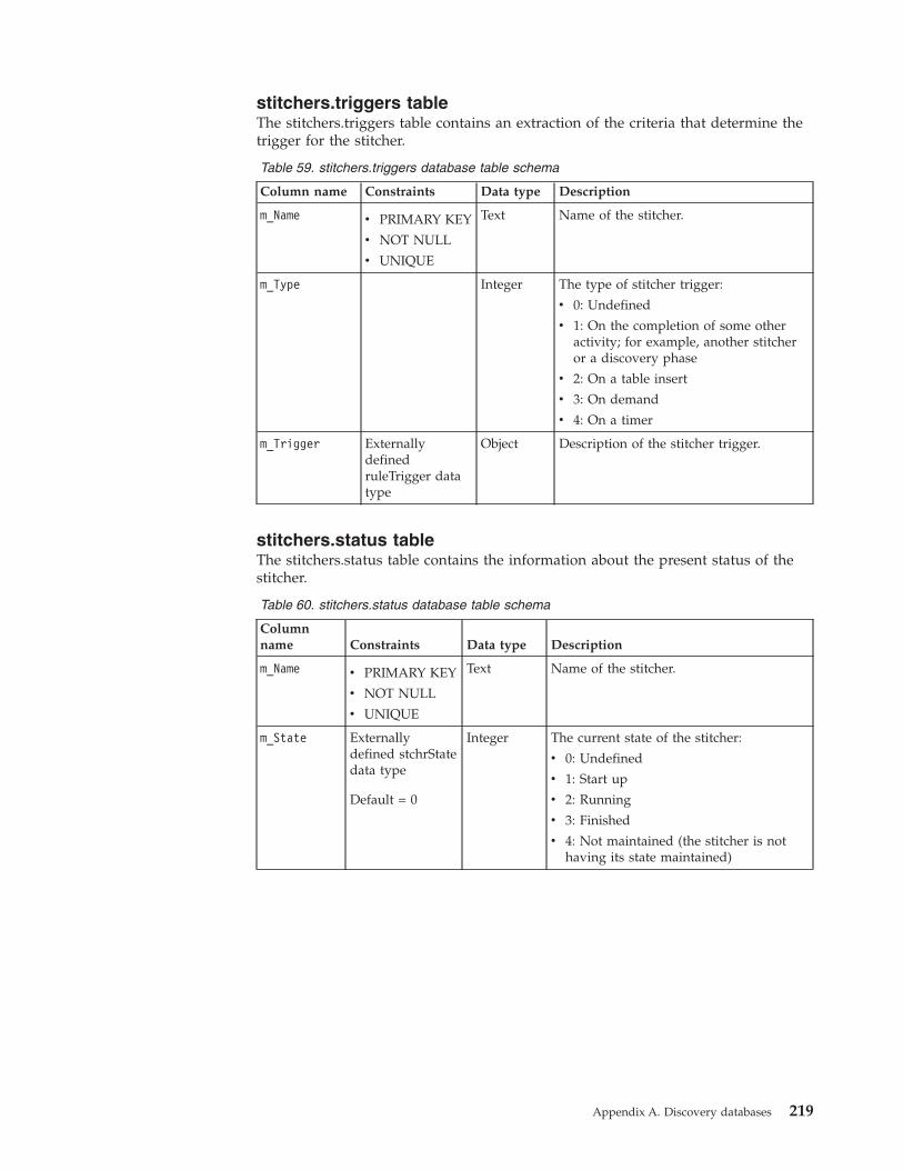
stitchers.triggers tableThe stitchers.triggers table contains an extraction of the criteria that determine thetrigger for the stitcher.
Table 59. stitchers.triggers database table schema
Column name Constraints Data type Description
m_Name v PRIMARY KEY
v NOT NULL
v UNIQUE
Text Name of the stitcher.
m_Type Integer The type of stitcher trigger:
v 0: Undefined
v 1: On the completion of some otheractivity; for example, another stitcheror a discovery phase
v 2: On a table insert
v 3: On demand
v 4: On a timer
m_Trigger ExternallydefinedruleTrigger datatype
Object Description of the stitcher trigger.
stitchers.status tableThe stitchers.status table contains the information about the present status of thestitcher.
Table 60. stitchers.status database table schema
Columnname Constraints Data type Description
m_Name v PRIMARY KEY
v NOT NULL
v UNIQUE
Text Name of the stitcher.
m_State Externallydefined stchrStatedata type
Default = 0
Integer The current state of the stitcher:
v 0: Undefined
v 1: Start up
v 2: Running
v 3: Finished
v 4: Not maintained (the stitcher is nothaving its state maintained)
Appendix A. Discovery databases 219
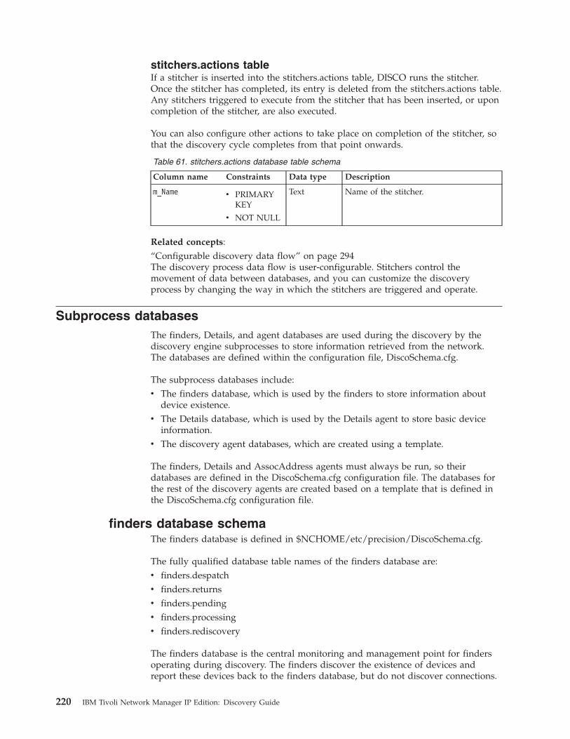
stitchers.actions tableIf a stitcher is inserted into the stitchers.actions table, DISCO runs the stitcher.Once the stitcher has completed, its entry is deleted from the stitchers.actions table.Any stitchers triggered to execute from the stitcher that has been inserted, or uponcompletion of the stitcher, are also executed.
You can also configure other actions to take place on completion of the stitcher, sothat the discovery cycle completes from that point onwards.
Table 61. stitchers.actions database table schema
Column name Constraints Data type Description
m_Name v PRIMARYKEY
v NOT NULL
Text Name of the stitcher.
Related concepts:“Configurable discovery data flow” on page 294The discovery process data flow is user-configurable. Stitchers control themovement of data between databases, and you can customize the discoveryprocess by changing the way in which the stitchers are triggered and operate.
Subprocess databasesThe finders, Details, and agent databases are used during the discovery by thediscovery engine subprocesses to store information retrieved from the network.The databases are defined within the configuration file, DiscoSchema.cfg.
The subprocess databases include:v The finders database, which is used by the finders to store information about
device existence.v The Details database, which is used by the Details agent to store basic device
information.v The discovery agent databases, which are created using a template.
The finders, Details and AssocAddress agents must always be run, so theirdatabases are defined in the DiscoSchema.cfg configuration file. The databases forthe rest of the discovery agents are created based on a template that is defined inthe DiscoSchema.cfg configuration file.
finders database schemaThe finders database is defined in $NCHOME/etc/precision/DiscoSchema.cfg.
The fully qualified database table names of the finders database are:v finders.despatchv finders.returnsv finders.pendingv finders.processingv finders.rediscovery
The finders database is the central monitoring and management point for findersoperating during discovery. The finders discover the existence of devices andreport these devices back to the finders database, but do not discover connections.
220 IBM Tivoli Network Manager IP Edition: Discovery Guide

Network entities reported by the finders are usually sent to the Details agent forretrieval of basic device information, although the discovery data flow is fullyconfigurable.Related concepts:“Discovery cycles” on page 285A discovery cycle has occurred when the discovery data flow for a particular cyclehas gone from start to finish. A full discovery might require more than one cycle.
finders.despatch tableThe finders.despatch table contains a record of all the requests sent to the findersand the current status of the requests.
Table 62. finders.despatch database table schema
Column name Constraints Data type Description
m_Finder v PRIMARY KEY
v NOT NULL
Text The name of the finderresponsible for therequest.
m_FindRequest v PRIMARY KEY
v UNIQUE
v NOT NULL
Text The OQL request sent tothe finder named above.
m_Request Status Integer The current status of therequest sent to the finder.
finders.returns tableWhen a finder finds a device, it returns the information to the finders.returns table,provided that the discovery is still in the device discovery phase, that is, datacollection phase one. If the discovery is in the blackout state, the finders return theinformation to the pending table.
The returns table serves as a transfer point, notifying the system that a deviceexists. By default, a stitcher sends the device information to the Details agent todiscover basic device information.
Table 63. finders.returns database table schema
Column name Constraints Data type Description
m_UniqueAddress v PRIMARY KEY
v UNIQUE
v NOT NULL
Text The IP address of thediscovered network entity.
m_Name Text The unique name of thenetwork entity.
m_Creator Text The finder that created thisrecord.
m_Protocol Integer The protocol of thediscovered device:
v 1: IP
v 2: IP-NAT
Appendix A. Discovery databases 221
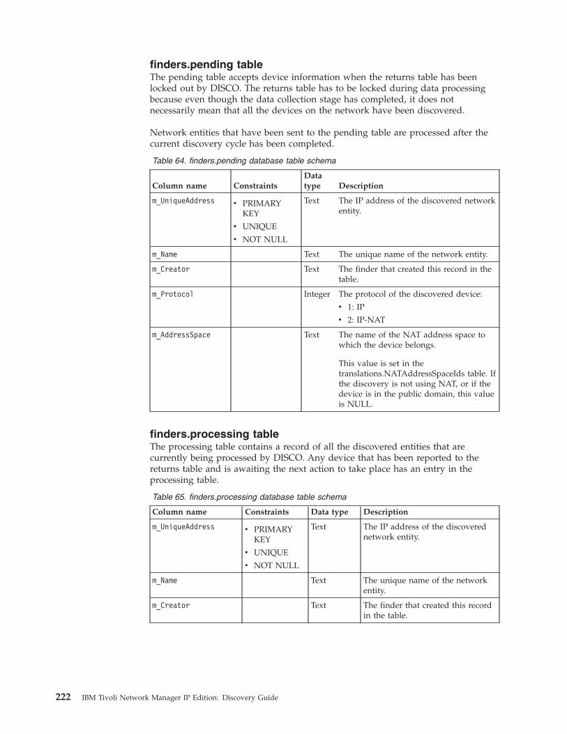
finders.pending tableThe pending table accepts device information when the returns table has beenlocked out by DISCO. The returns table has to be locked during data processingbecause even though the data collection stage has completed, it does notnecessarily mean that all the devices on the network have been discovered.
Network entities that have been sent to the pending table are processed after thecurrent discovery cycle has been completed.
Table 64. finders.pending database table schema
Column name ConstraintsDatatype Description
m_UniqueAddress v PRIMARYKEY
v UNIQUE
v NOT NULL
Text The IP address of the discovered networkentity.
m_Name Text The unique name of the network entity.
m_Creator Text The finder that created this record in thetable.
m_Protocol Integer The protocol of the discovered device:
v 1: IP
v 2: IP-NAT
m_AddressSpace Text The name of the NAT address space towhich the device belongs.
This value is set in thetranslations.NATAddressSpaceIds table. Ifthe discovery is not using NAT, or if thedevice is in the public domain, this valueis NULL.
finders.processing tableThe processing table contains a record of all the discovered entities that arecurrently being processed by DISCO. Any device that has been reported to thereturns table and is awaiting the next action to take place has an entry in theprocessing table.
Table 65. finders.processing database table schema
Column name Constraints Data type Description
m_UniqueAddress v PRIMARYKEY
v UNIQUE
v NOT NULL
Text The IP address of the discoverednetwork entity.
m_Name Text The unique name of the networkentity.
m_Creator Text The finder that created this recordin the table.
222 IBM Tivoli Network Manager IP Edition: Discovery Guide
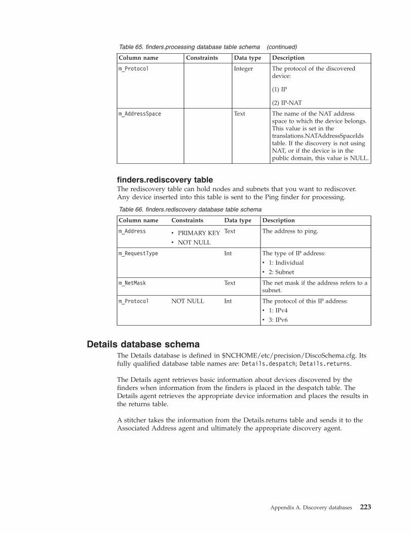
Table 65. finders.processing database table schema (continued)
Column name Constraints Data type Description
m_Protocol Integer The protocol of the discovereddevice:
(1) IP
(2) IP-NAT
m_AddressSpace Text The name of the NAT addressspace to which the device belongs.This value is set in thetranslations.NATAddressSpaceIdstable. If the discovery is not usingNAT, or if the device is in thepublic domain, this value is NULL.
finders.rediscovery tableThe rediscovery table can hold nodes and subnets that you want to rediscover.Any device inserted into this table is sent to the Ping finder for processing.
Table 66. finders.rediscovery database table schema
Column name Constraints Data type Description
m_Address v PRIMARY KEY
v NOT NULL
Text The address to ping.
m_RequestType Int The type of IP address:
v 1: Individual
v 2: Subnet
m_NetMask Text The net mask if the address refers to asubnet.
m_Protocol NOT NULL Int The protocol of this IP address:
v 1: IPv4
v 3: IPv6
Details database schemaThe Details database is defined in $NCHOME/etc/precision/DiscoSchema.cfg. Itsfully qualified database table names are: Details.despatch; Details.returns.
The Details agent retrieves basic information about devices discovered by thefinders when information from the finders is placed in the despatch table. TheDetails agent retrieves the appropriate device information and places the results inthe returns table.
A stitcher takes the information from the Details.returns table and sends it to theAssociated Address agent and ultimately the appropriate discovery agent.
Appendix A. Discovery databases 223
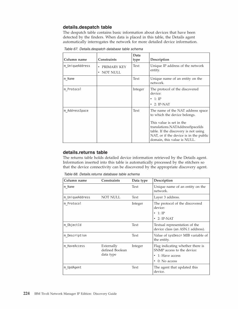
details.despatch tableThe despatch table contains basic information about devices that have beendetected by the finders. When data is placed in this table, the Details agentautomatically interrogates the network for more detailed device information.
Table 67. Details.despatch database table schema
Column name ConstraintsDatatype Description
m_UniqueAddress v PRIMARY KEY
v NOT NULL
Text Unique IP address of the networkentity.
m_Name Text Unique name of an entity on thenetwork.
m_Protocol Integer The protocol of the discovereddevice:
v 1: IP
v 2: IP-NAT
m_AddressSpace Text The name of the NAT address spaceto which the device belongs.
This value is set in thetranslations.NATAddressSpaceIdstable. If the discovery is not usingNAT, or if the device is in the publicdomain, this value is NULL.
details.returns tableThe returns table holds detailed device information retrieved by the Details agent.Information inserted into this table is automatically processed by the stitchers sothat the device connectivity can be discovered by the appropriate discovery agent.
Table 68. Details.returns database table schema
Column name Constraints Data type Description
m_Name Text Unique name of an entity on thenetwork.
m_UniqueAddress NOT NULL Text Layer 3 address.
m_Protocol Integer The protocol of the discovereddevice:
v 1: IP
v 2: IP-NAT
m_ObjectId Text Textual representation of thedevice class (an ASN.1 address).
m_Description Text Value of sysDescr MIB variable ofthe entity.
m_HaveAccess Externallydefined Booleandata type
Integer Flag indicating whether there isSNMP access to the device:
v 1: Have access
v 0: No access
m_UpdAgent Text The agent that updated thisdevice.
224 IBM Tivoli Network Manager IP Edition: Discovery Guide
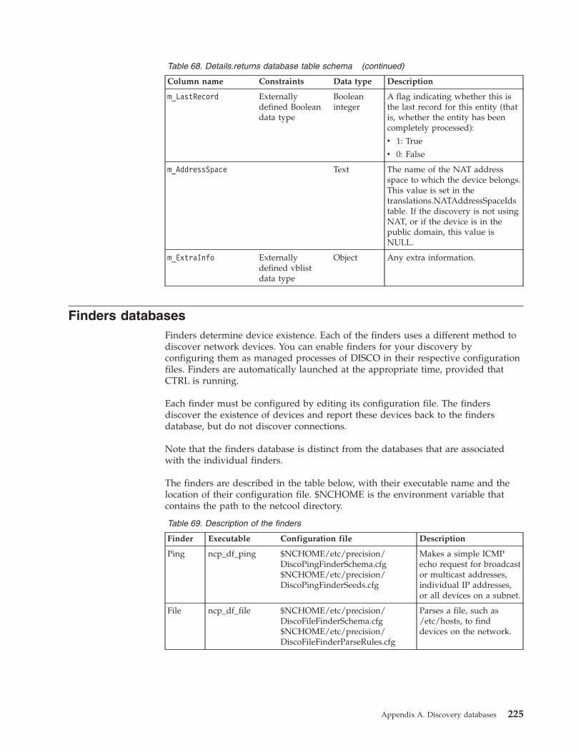
Table 68. Details.returns database table schema (continued)
Column name Constraints Data type Description
m_LastRecord Externallydefined Booleandata type
Booleaninteger
A flag indicating whether this isthe last record for this entity (thatis, whether the entity has beencompletely processed):
v 1: True
v 0: False
m_AddressSpace Text The name of the NAT addressspace to which the device belongs.This value is set in thetranslations.NATAddressSpaceIdstable. If the discovery is not usingNAT, or if the device is in thepublic domain, this value isNULL.
m_ExtraInfo Externallydefined vblistdata type
Object Any extra information.
Finders databasesFinders determine device existence. Each of the finders uses a different method todiscover network devices. You can enable finders for your discovery byconfiguring them as managed processes of DISCO in their respective configurationfiles. Finders are automatically launched at the appropriate time, provided thatCTRL is running.
Each finder must be configured by editing its configuration file. The findersdiscover the existence of devices and report these devices back to the findersdatabase, but do not discover connections.
Note that the finders database is distinct from the databases that are associatedwith the individual finders.
The finders are described in the table below, with their executable name and thelocation of their configuration file. $NCHOME is the environment variable thatcontains the path to the netcool directory.
Table 69. Description of the finders
Finder Executable Configuration file Description
Ping ncp_df_ping $NCHOME/etc/precision/DiscoPingFinderSchema.cfg$NCHOME/etc/precision/DiscoPingFinderSeeds.cfg
Makes a simple ICMPecho request for broadcastor multicast addresses,individual IP addresses,or all devices on a subnet.
File ncp_df_file $NCHOME/etc/precision/DiscoFileFinderSchema.cfg$NCHOME/etc/precision/DiscoFileFinderParseRules.cfg
Parses a file, such as/etc/hosts, to finddevices on the network.
Appendix A. Discovery databases 225
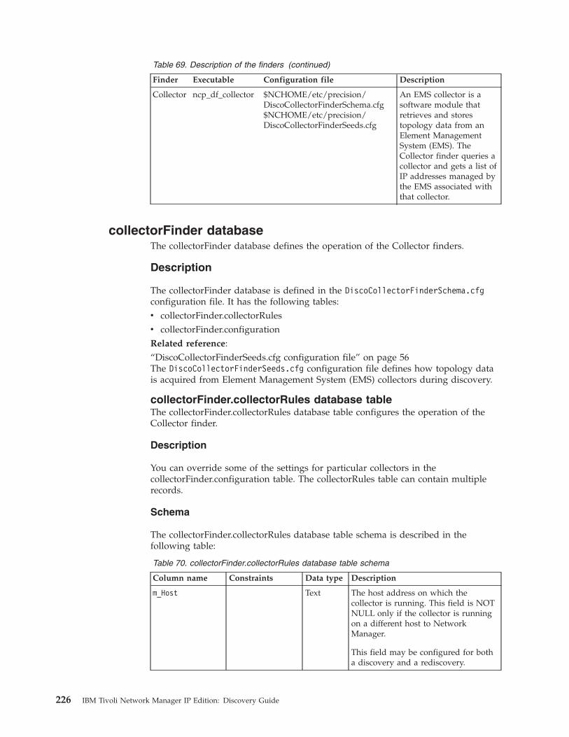
Table 69. Description of the finders (continued)
Finder Executable Configuration file Description
Collector ncp_df_collector $NCHOME/etc/precision/DiscoCollectorFinderSchema.cfg$NCHOME/etc/precision/DiscoCollectorFinderSeeds.cfg
An EMS collector is asoftware module thatretrieves and storestopology data from anElement ManagementSystem (EMS). TheCollector finder queries acollector and gets a list ofIP addresses managed bythe EMS associated withthat collector.
collectorFinder databaseThe collectorFinder database defines the operation of the Collector finders.
Description
The collectorFinder database is defined in the DiscoCollectorFinderSchema.cfgconfiguration file. It has the following tables:v collectorFinder.collectorRulesv collectorFinder.configurationRelated reference:“DiscoCollectorFinderSeeds.cfg configuration file” on page 56The DiscoCollectorFinderSeeds.cfg configuration file defines how topology datais acquired from Element Management System (EMS) collectors during discovery.
collectorFinder.collectorRules database tableThe collectorFinder.collectorRules database table configures the operation of theCollector finder.
Description
You can override some of the settings for particular collectors in thecollectorFinder.configuration table. The collectorRules table can contain multiplerecords.
Schema
The collectorFinder.collectorRules database table schema is described in thefollowing table:
Table 70. collectorFinder.collectorRules database table schema
Column name Constraints Data type Description
m_Host Text The host address on which thecollector is running. This field is NOTNULL only if the collector is runningon a different host to NetworkManager.
This field may be configured for botha discovery and a rediscovery.
226 IBM Tivoli Network Manager IP Edition: Discovery Guide
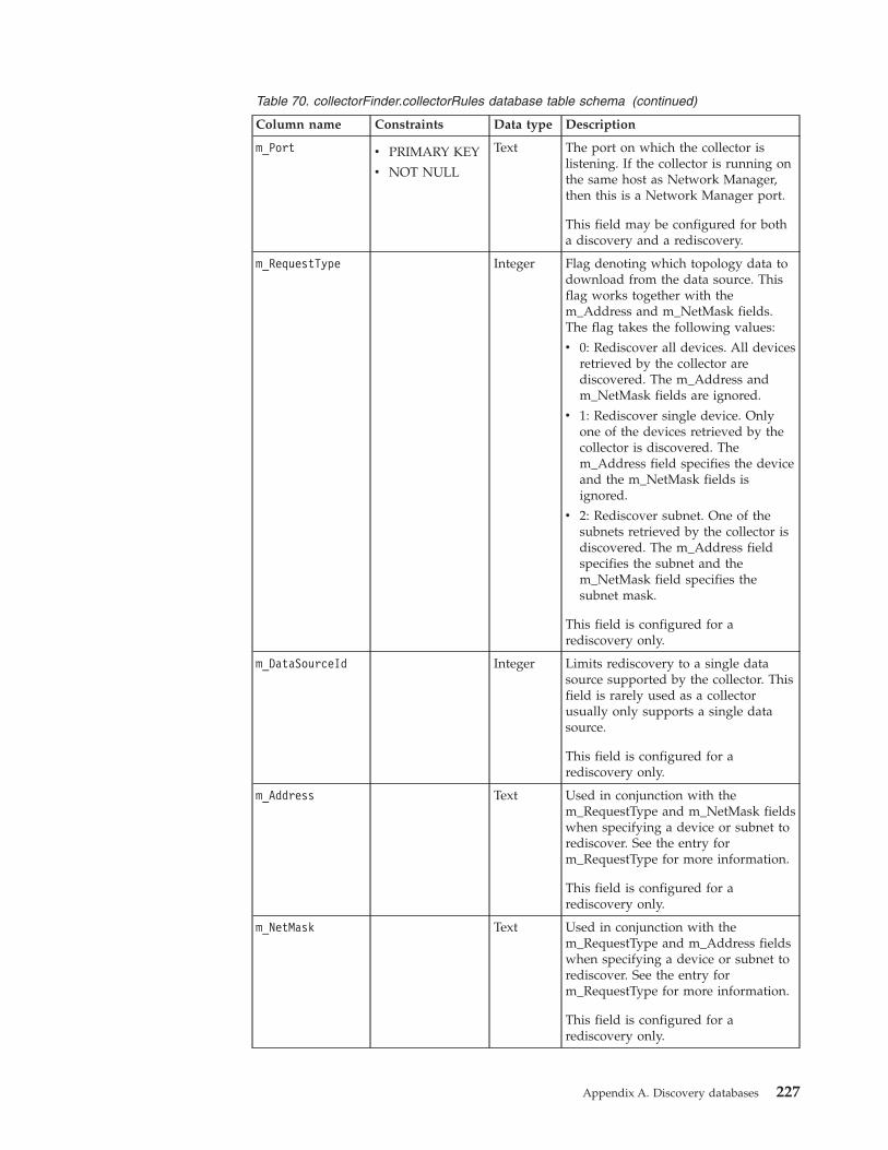
Table 70. collectorFinder.collectorRules database table schema (continued)
Column name Constraints Data type Description
m_Port v PRIMARY KEY
v NOT NULL
Text The port on which the collector islistening. If the collector is running onthe same host as Network Manager,then this is a Network Manager port.
This field may be configured for botha discovery and a rediscovery.
m_RequestType Integer Flag denoting which topology data todownload from the data source. Thisflag works together with them_Address and m_NetMask fields.The flag takes the following values:
v 0: Rediscover all devices. All devicesretrieved by the collector arediscovered. The m_Address andm_NetMask fields are ignored.
v 1: Rediscover single device. Onlyone of the devices retrieved by thecollector is discovered. Them_Address field specifies the deviceand the m_NetMask fields isignored.
v 2: Rediscover subnet. One of thesubnets retrieved by the collector isdiscovered. The m_Address fieldspecifies the subnet and them_NetMask field specifies thesubnet mask.
This field is configured for arediscovery only.
m_DataSourceId Integer Limits rediscovery to a single datasource supported by the collector. Thisfield is rarely used as a collectorusually only supports a single datasource.
This field is configured for arediscovery only.
m_Address Text Used in conjunction with them_RequestType and m_NetMask fieldswhen specifying a device or subnet torediscover. See the entry form_RequestType for more information.
This field is configured for arediscovery only.
m_NetMask Text Used in conjunction with them_RequestType and m_Address fieldswhen specifying a device or subnet torediscover. See the entry form_RequestType for more information.
This field is configured for arediscovery only.
Appendix A. Discovery databases 227
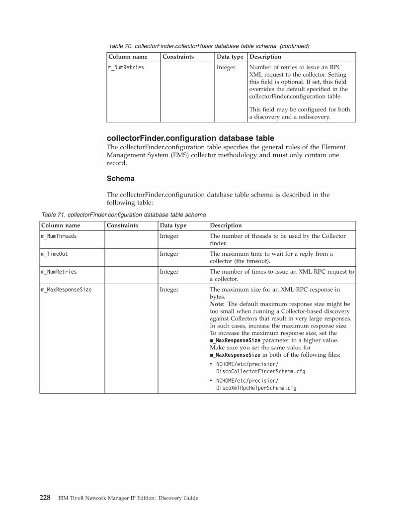
Table 70. collectorFinder.collectorRules database table schema (continued)
Column name Constraints Data type Description
m_NumRetries Integer Number of retries to issue an RPCXML request to the collector. Settingthis field is optional. If set, this fieldoverrides the default specified in thecollectorFinder.configuration table.
This field may be configured for botha discovery and a rediscovery.
collectorFinder.configuration database tableThe collectorFinder.configuration table specifies the general rules of the ElementManagement System (EMS) collector methodology and must only contain onerecord.
Schema
The collectorFinder.configuration database table schema is described in thefollowing table:
Table 71. collectorFinder.configuration database table schema
Column name Constraints Data type Description
m_NumThreads Integer The number of threads to be used by the Collectorfinder.
m_TimeOut Integer The maximum time to wait for a reply from acollector (the timeout).
m_NumRetries Integer The number of times to issue an XML-RPC request toa collector.
m_MaxResponseSize Integer The maximum size for an XML-RPC response inbytes.Note: The default maximum response size might betoo small when running a Collector-based discoveryagainst Collectors that result in very large responses.In such cases, increase the maximum response size.To increase the maximum response size, set them_MaxResponseSize parameter to a higher value.Make sure you set the same value form_MaxResponseSize in both of the following files:
v NCHOME/etc/precision/DiscoCollectorFinderSchema.cfg
v NCHOME/etc/precision/DiscoXmlRpcHelperSchema.cfg
228 IBM Tivoli Network Manager IP Edition: Discovery Guide
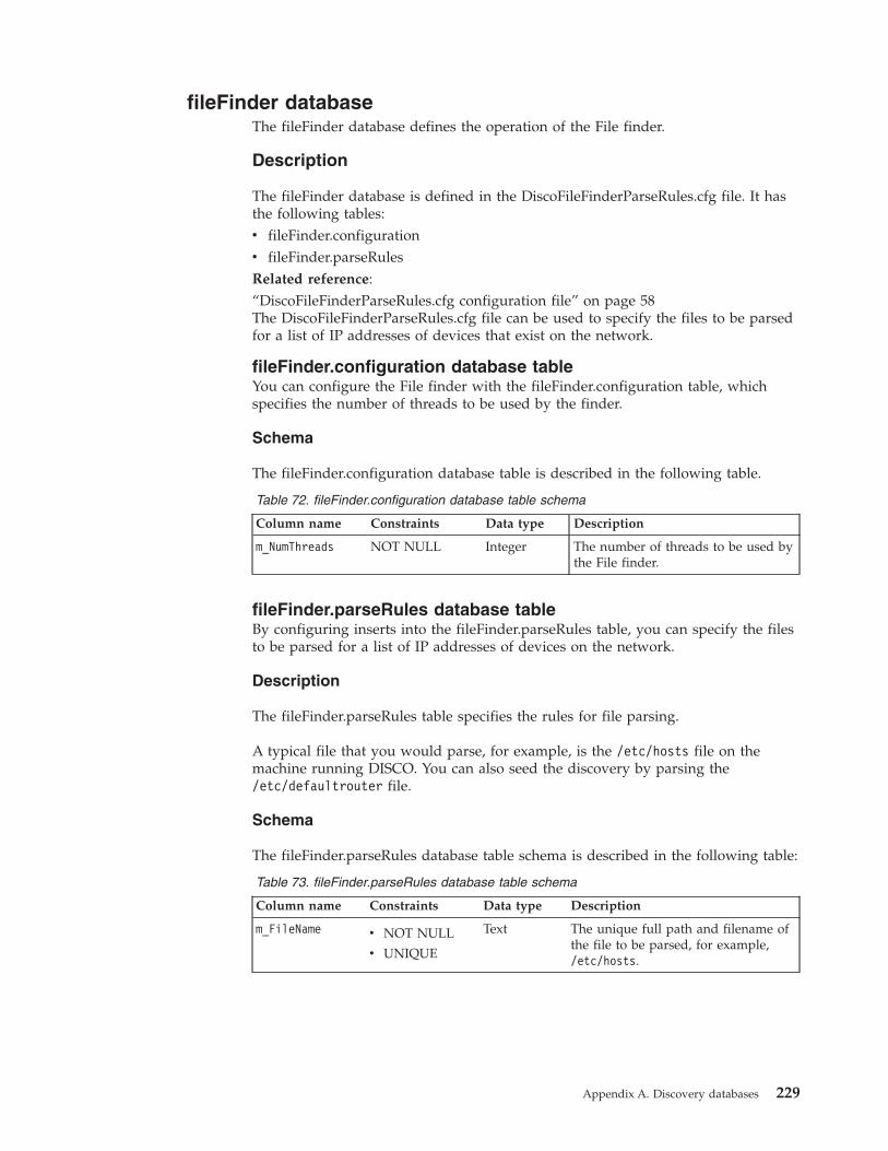
fileFinder databaseThe fileFinder database defines the operation of the File finder.
Description
The fileFinder database is defined in the DiscoFileFinderParseRules.cfg file. It hasthe following tables:v fileFinder.configurationv fileFinder.parseRulesRelated reference:“DiscoFileFinderParseRules.cfg configuration file” on page 58The DiscoFileFinderParseRules.cfg file can be used to specify the files to be parsedfor a list of IP addresses of devices that exist on the network.
fileFinder.configuration database tableYou can configure the File finder with the fileFinder.configuration table, whichspecifies the number of threads to be used by the finder.
Schema
The fileFinder.configuration database table is described in the following table.
Table 72. fileFinder.configuration database table schema
Column name Constraints Data type Description
m_NumThreads NOT NULL Integer The number of threads to be used bythe File finder.
fileFinder.parseRules database tableBy configuring inserts into the fileFinder.parseRules table, you can specify the filesto be parsed for a list of IP addresses of devices on the network.
Description
The fileFinder.parseRules table specifies the rules for file parsing.
A typical file that you would parse, for example, is the /etc/hosts file on themachine running DISCO. You can also seed the discovery by parsing the/etc/defaultrouter file.
Schema
The fileFinder.parseRules database table schema is described in the following table:
Table 73. fileFinder.parseRules database table schema
Column name Constraints Data type Description
m_FileName v NOT NULL
v UNIQUE
Text The unique full path and filename ofthe file to be parsed, for example,/etc/hosts.
Appendix A. Discovery databases 229
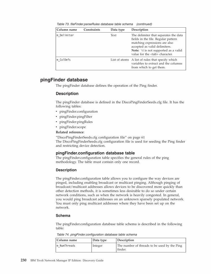
Table 73. fileFinder.parseRules database table schema (continued)
Column name Constraints Data type Description
m_Delimiter Text The delimiter that separates the datafields in the file. Regular patternmatching expressions are alsoaccepted as valid delimiters.Note: \t is not supported as a validvalue for the <tab> character.
m_ColDefs List of atoms A list of rules that specify whichvariables to extract and the columnsfrom which to get them.
pingFinder databaseThe pingFinder database defines the operation of the Ping finder.
Description
The pingFinder database is defined in the DiscoPingFinderSeeds.cfg file. It has thefollowing tables:v pingFinder.configurationv pingFinder.pingFilterv pingFinder.pingRulesv pingFinder.scopeRelated reference:“DiscoPingFinderSeeds.cfg configuration file” on page 61The DiscoPingFinderSeeds.cfg configuration file is used for seeding the Ping finderand restricting device detection.
pingFinder.configuration database tableThe pingFinder.configuration table specifies the general rules of the pingmethodology. The table must contain only one record.
Description
The pingFinder.configuration table allows you to configure the way devices arepinged, including enabling broadcast or multicast pinging. Although pinging ofbroadcast/multicast addresses allows devices to be discovered more quickly thanother detection methods, it is sometimes less desirable to do so under certainnetwork conditions, such as when the network is heavily congested. In general,you would ping broadcast addresses on an unknown sparsely populated network.You must only ping multicast addresses where they have been set up on thenetwork.
Schema
The pingFinder.configuration database table schema is described in the followingtable:
Table 74. pingFinder.configuration database table schema
Column name Data type Description
m_NumThreads Integer The number of threads to be used by the Pingfinder.
230 IBM Tivoli Network Manager IP Edition: Discovery Guide
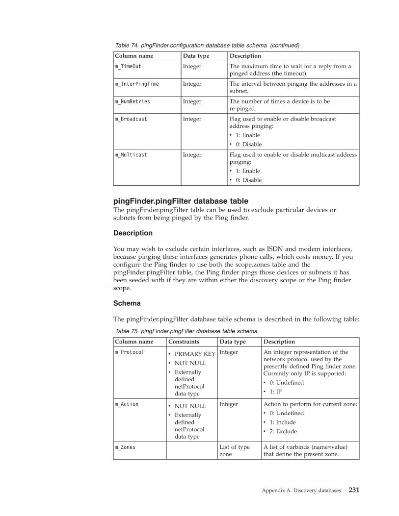
Table 74. pingFinder.configuration database table schema (continued)
Column name Data type Description
m_TimeOut Integer The maximum time to wait for a reply from apinged address (the timeout).
m_InterPingTime Integer The interval between pinging the addresses in asubnet.
m_NumRetries Integer The number of times a device is to bere-pinged.
m_Broadcast Integer Flag used to enable or disable broadcastaddress pinging:
v 1: Enable
v 0: Disable
m_Multicast Integer Flag used to enable or disable multicast addresspinging:
v 1: Enable
v 0: Disable
pingFinder.pingFilter database tableThe pingFinder.pingFilter table can be used to exclude particular devices orsubnets from being pinged by the Ping finder.
Description
You may wish to exclude certain interfaces, such as ISDN and modem interfaces,because pinging these interfaces generates phone calls, which costs money. If youconfigure the Ping finder to use both the scope.zones table and thepingFinder.pingFilter table, the Ping finder pings those devices or subnets it hasbeen seeded with if they are within either the discovery scope or the Ping finderscope.
Schema
The pingFinder.pingFilter database table schema is described in the following table:
Table 75. pingFinder.pingFilter database table schema
Column name Constraints Data type Description
m_Protocol v PRIMARY KEY
v NOT NULL
v ExternallydefinednetProtocoldata type
Integer An integer representation of thenetwork protocol used by thepresently defined Ping finder zone.Currently only IP is supported:
v 0: Undefined
v 1: IP
m_Action v NOT NULL
v ExternallydefinednetProtocoldata type
Integer Action to perform for current zone:
v 0: Undefined
v 1: Include
v 2: Exclude
m_Zones List of typezone
A list of varbinds (name=value)that define the present zone.
Appendix A. Discovery databases 231

Table 75. pingFinder.pingFilter database table schema (continued)
Column name Constraints Data type Description
m_AddressSpace Text The name of the NAT addressspace to which the device belongs.This value is set in thetranslations.NATAddressSpaceIdstable. If the discovery is not usingNAT, or if the device is in thepublic domain, this value is NULL.
pingFinder.pingRules database tableThe pingFinder.pingRules table specifies the different addresses and subnets to bepinged by the Ping finder.
Description
The pingRules table can contain multiple records.
Schema
The pingFinder.pingRules table is described in the following table.
Table 76. pingFinder.pingRules database table schema
Column name Constraints Data type Description
m_Address v PRIMARY KEY
v NOT NULL
Text The address to ping.
m_RequestType Integer Flag denoting address type:
v 1: Individual
v 2: Subnet
m_NetMask Text The subnet mask. If a value isspecified for this field, it automaticallyimplies that the address is a subnetaddress.
m_TimeOut Integer Maximum time to wait for response.This value overrides the defaulttimeout specified in the configurationtable.
m_NumRetries Integer Maximum number of times toreattempt the ping. This valueoverrides the default value.
pingFinder.scope database tableThe pingFinder.scope table defines the scope of the Ping finder.
Description
You can use the pingFinder.scope table to configure the way the Ping finder checkswhether it is allowed to ping a particular device. You can exclude particulardevices or subnets from being pinged by the Ping finder.
232 IBM Tivoli Network Manager IP Edition: Discovery Guide
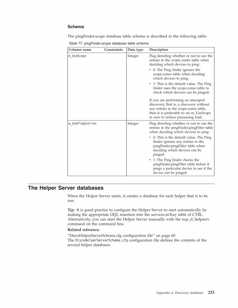
Schema
The pingFinder.scope database table schema is described in the following table:
Table 77. pingFinder.scope database table schema
Column name Constraints Data type Description
m_UseScope Integer Flag denoting whether or not to use theentries in the scope.zones table whendeciding which devices to ping:
v 0: The Ping finder ignores thescope.zones table when decidingwhich devices to ping.
v 1: This is the default value. The Pingfinder uses the scope.zones table tocheck which devices can be pinged.
If you are performing an unscopeddiscovery, that is, a discovery withoutany entries in the scope.zones table,then it is preferable to set m_UseScopeto zero to reduce processing load.
m_UsePingEntries Integer Flag denoting whether or not to use theentries in the pingFinder.pingFilter tablewhen deciding which devices to ping:
v 0: This is the default value. The Pingfinder ignores any entries in thepingFinder.pingFilter table whendeciding which devices can bepinged.
v 1: The Ping finder checks thepingFinder.pingFilter table before itpings a particular device to see if thedevice can be pinged.
The Helper Server databasesWhen the Helper Server starts, it creates a database for each helper that is to berun.
Tip: It is good practice to configure the Helper Server to start automatically bymaking the appropriate OQL insertion into the services.inTray table of CTRL.Alternatively, you can start the Helper Server manually with the ncp_d_helpservcommand on the command line.Related reference:“DiscoHelperServerSchema.cfg configuration file” on page 60The DiscoHelperServerSchema.cfg configuration file defines the contents of theseveral helper databases.
Appendix A. Discovery databases 233
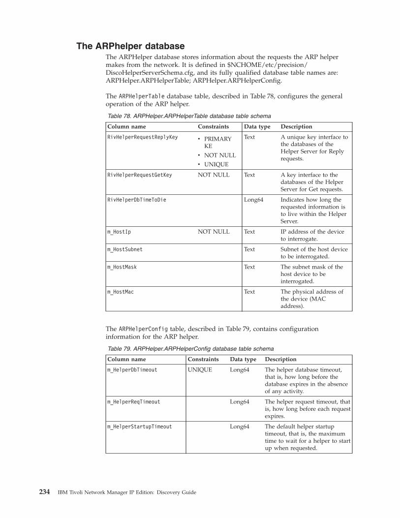
The ARPhelper databaseThe ARPHelper database stores information about the requests the ARP helpermakes from the network. It is defined in $NCHOME/etc/precision/DiscoHelperServerSchema.cfg, and its fully qualified database table names are:ARPHelper.ARPHelperTable; ARPHelper.ARPHelperConfig.
The ARPHelperTable database table, described in Table 78, configures the generaloperation of the ARP helper.
Table 78. ARPHelper.ARPHelperTable database table schema
Column name Constraints Data type Description
RivHelperRequestReplyKey v PRIMARYKE
v NOT NULL
v UNIQUE
Text A unique key interface tothe databases of theHelper Server for Replyrequests.
RivHelperRequestGetKey NOT NULL Text A key interface to thedatabases of the HelperServer for Get requests.
RivHelperDbTimeToDie Long64 Indicates how long therequested information isto live within the HelperServer.
m_HostIp NOT NULL Text IP address of the deviceto interrogate.
m_HostSubnet Text Subnet of the host deviceto be interrogated.
m_HostMask Text The subnet mask of thehost device to beinterrogated.
m_HostMac Text The physical address ofthe device (MACaddress).
The ARPHelperConfig table, described in Table 79, contains configurationinformation for the ARP helper.
Table 79. ARPHelper.ARPHelperConfig database table schema
Column name Constraints Data type Description
m_HelperDbTimeout UNIQUE Long64 The helper database timeout,that is, how long before thedatabase expires in the absenceof any activity.
m_HelperReqTimeout Long64 The helper request timeout, thatis, how long before each requestexpires.
m_HelperStartupTimeout Long64 The default helper startuptimeout, that is, the maximumtime to wait for a helper to startup when requested.
234 IBM Tivoli Network Manager IP Edition: Discovery Guide
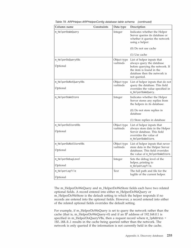
Table 79. ARPHelper.ARPHelperConfig database table schema (continued)
Column name Constraints Data type Description
m_HelperDoWeQuery Integer Indicates whether the HelperServer queries its database orwhether it queries the networkusing a helper:
(0) Do not use cache
(1) Use cache
m_HelperDoQueryVBs
Optional
Object typevarbinds
List of helper inputs thatalways query the databasebefore querying the network. Ifthe item is found in thedatabase then the network isnot queried.
m_HelperDoNotQueryVBs
Optional
Object typevarbinds
List of helper inputs that do notquery the database. This fieldoverrides the value specified inm_HelperDoWeQuery.
m_HelperDoWeStore Integer Indicates whether the HelperServer stores any replies fromthe helpers in its database:
(0) Do not store replies indatabase
(1) Store replies in database
m_HelperDoStoreVBs
Optional
Object typevarbinds
List of helper inputs thatalways store data in the HelperServer database. This fieldoverrides the value ofm_HelperDoWeStore.
m_HelperDoNotStoreVBs
Optional
Object typevarbinds
List of helper inputs that neverstore data in the Helper Serverdatabases. This field overridesthe value of m_HelperDoWeStore.
m_HelperDebugLevel
Optional
Integer Sets the debug level of thehelper, printing tom_HelperLogfile.
m_HelperLogfile
Optional
Text The full path and file for thelogfile of the current helper.
The m_HelperDoWeQuery and m_HelperDoWeStore fields each have two relatedoptional fields. A record entered into either m_HelperDoWeQuery orm_HelperDoWeStore is the default setting to which the helper responds if norecords are entered into the optional fields. However, a record entered into eitherof the related optional fields overrides the default setting.
For example, if m_HelperDoWeQuery is set to query the network rather than thecache (that is, m_HelperDoWeQuery=0) and if an IP address of 192.168.0.1 isspecified in m_HelperDoQueryVBs, then a request record where m_IpAddress =192.168.0.1 results in the cache being queried rather than the network. Thenetwork is only queried if the information is not currently held in the cache.
Appendix A. Discovery databases 235
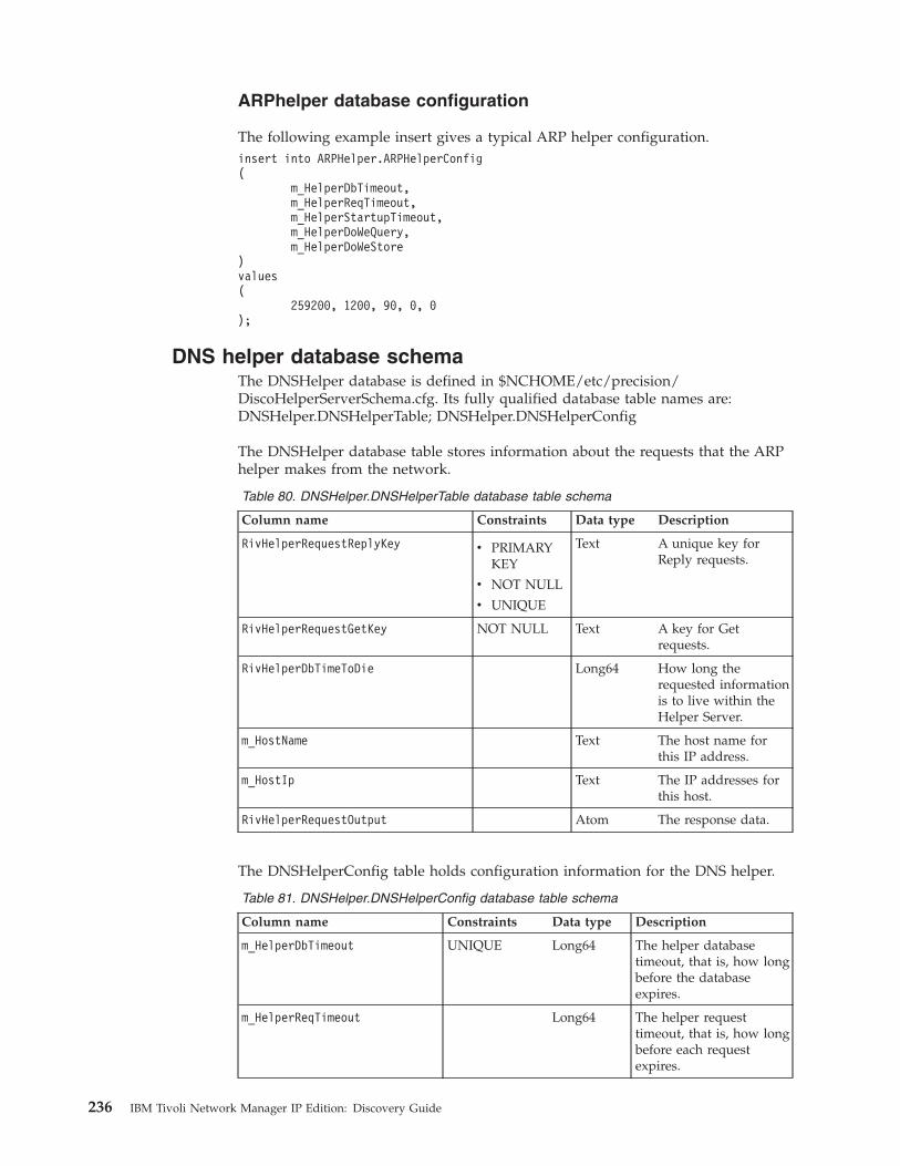
ARPhelper database configuration
The following example insert gives a typical ARP helper configuration.insert into ARPHelper.ARPHelperConfig(
m_HelperDbTimeout,m_HelperReqTimeout,m_HelperStartupTimeout,m_HelperDoWeQuery,m_HelperDoWeStore
)values(
259200, 1200, 90, 0, 0);
DNS helper database schemaThe DNSHelper database is defined in $NCHOME/etc/precision/DiscoHelperServerSchema.cfg. Its fully qualified database table names are:DNSHelper.DNSHelperTable; DNSHelper.DNSHelperConfig
The DNSHelper database table stores information about the requests that the ARPhelper makes from the network.
Table 80. DNSHelper.DNSHelperTable database table schema
Column name Constraints Data type Description
RivHelperRequestReplyKey v PRIMARYKEY
v NOT NULL
v UNIQUE
Text A unique key forReply requests.
RivHelperRequestGetKey NOT NULL Text A key for Getrequests.
RivHelperDbTimeToDie Long64 How long therequested informationis to live within theHelper Server.
m_HostName Text The host name forthis IP address.
m_HostIp Text The IP addresses forthis host.
RivHelperRequestOutput Atom The response data.
The DNSHelperConfig table holds configuration information for the DNS helper.
Table 81. DNSHelper.DNSHelperConfig database table schema
Column name Constraints Data type Description
m_HelperDbTimeout UNIQUE Long64 The helper databasetimeout, that is, how longbefore the databaseexpires.
m_HelperReqTimeout Long64 The helper requesttimeout, that is, how longbefore each requestexpires.
236 IBM Tivoli Network Manager IP Edition: Discovery Guide
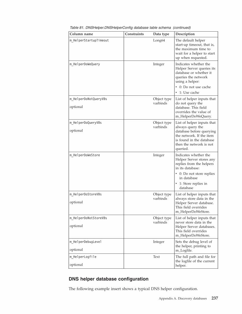
Table 81. DNSHelper.DNSHelperConfig database table schema (continued)
Column name Constraints Data type Description
m_HelperStartupTimeout Long64 The default helperstart-up timeout, that is,the maximum time towait for a helper to startup when requested.
m_HelperDoWeQuery Integer Indicates whether theHelper Server queries itsdatabase or whether itqueries the networkusing a helper:
v 0: Do not use cache
v 1: Use cache
m_HelperDoNotQueryVBs
optional
Object typevarbinds
List of helper inputs thatdo not query thedatabase. This fieldoverrides the value ofm_HelperDoWeQuery.
m_HelperDoQueryVBs
optional
Object typevarbinds
List of helper inputs thatalways query thedatabase before queryingthe network. If the itemis found in the databasethen the network is notqueried.
m_HelperDoWeStore Integer Indicates whether theHelper Server stores anyreplies from the helpersin its database:
v 0: Do not store repliesin database
v 1: Store replies indatabase
m_HelperDoStoreVBs
optional
Object typevarbinds
List of helper inputs thatalways store data in theHelper Server database.This field overridesm_HelperDoWeStore.
m_HelperDoNotStoreVBs
optional
Object typevarbinds
List of helper inputs thatnever store data in theHelper Server databases.This field overridesm_HelperDoWeStore.
m_HelperDebugLevel
optional
Integer Sets the debug level ofthe helper, printing tom_Logfile.
m_HelperLogfile
optional
Text The full path and file forthe logfile of the currenthelper.
DNS helper database configuration
The following example insert shows a typical DNS helper configuration.
Appendix A. Discovery databases 237

insert into DNSHelper.DNSHelperConfig(
m_HelperDbTimeout,m_HelperReqTimeout,m_HelperStartupTimeout,m_HelperDoWeQuery,m_HelperDoWeStore
)values(
259200, 1200, 90, 0, 0);
Ping helper database schemaThe Ping helper database is defined in $NCHOME/etc/precision/DiscoHelperServerSchema.cfg. Its fully qualified database table names are:PingHelper.PingHelperTable; PingHelper.PingHelperConfig;pingHelper.configuration
The schema of the PingHelper.PingHelperTable database table is described inTable 82.
Table 82. PingHelper.PingHelperTable database table schema
Column name Constraints Data type Description
RivHelperRequestReplyKey v PRIMARYKEY
v NOT NULL
v UNIQUE
Text A key interface tothe databases of theHelper Server forReply requests.
RivHelperRequestGetKey NOT NULL Text A key interface tothe databases of theHelper Server forGet requests.
RivHelperDbTimeToDie Long64 How long therequestedinformation is to livewithin the HelperServer.
m_HostIp Atom IP address to ping.
m_HostSubnet Text Subnet of the IPaddress to ping.
m_HostMask Text The subnet mask ofthe address to ping.
m_PingRequestType Integer The type of pingrequest:
v 1: Individualaddress
v 2: Subnet
m_PingResponseType Integer Type of reply to theping.
m_PingRetries Integer Number of retriesfor the ping.
m_PingTimeout Integer Maximum time towait for reply.
RivHelperRequestOutput Atom The response data.
238 IBM Tivoli Network Manager IP Edition: Discovery Guide
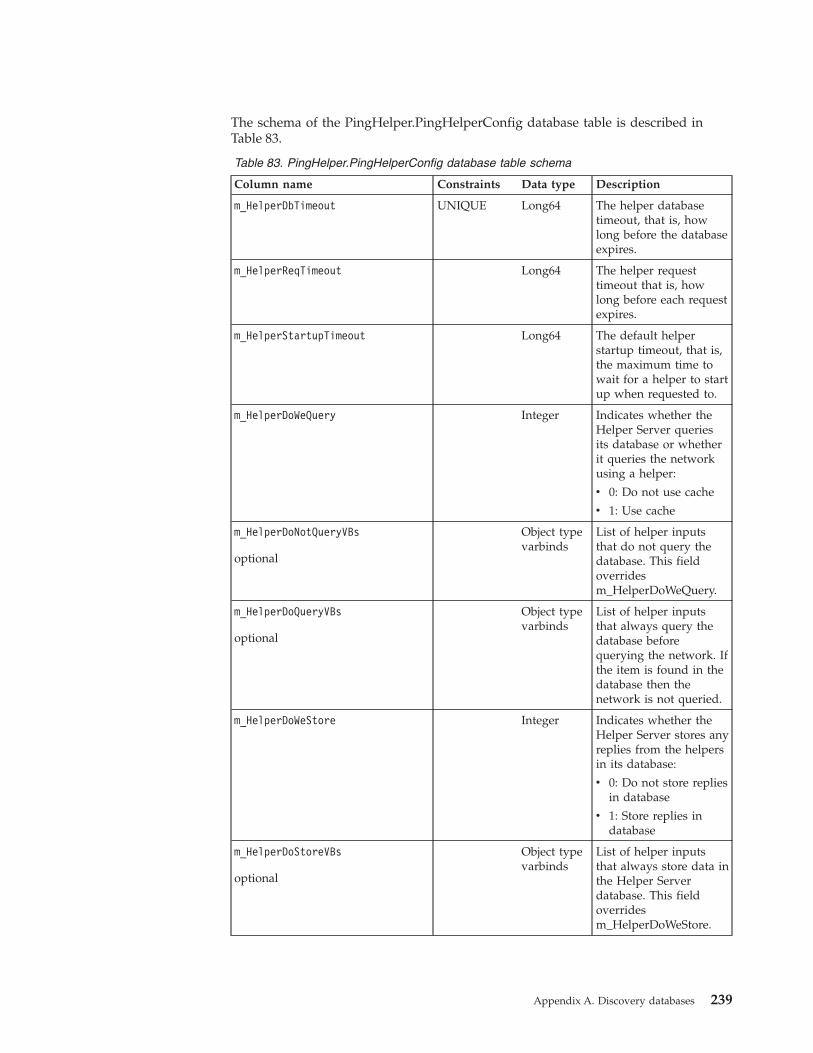
The schema of the PingHelper.PingHelperConfig database table is described inTable 83.
Table 83. PingHelper.PingHelperConfig database table schema
Column name Constraints Data type Description
m_HelperDbTimeout UNIQUE Long64 The helper databasetimeout, that is, howlong before the databaseexpires.
m_HelperReqTimeout Long64 The helper requesttimeout that is, howlong before each requestexpires.
m_HelperStartupTimeout Long64 The default helperstartup timeout, that is,the maximum time towait for a helper to startup when requested to.
m_HelperDoWeQuery Integer Indicates whether theHelper Server queriesits database or whetherit queries the networkusing a helper:
v 0: Do not use cache
v 1: Use cache
m_HelperDoNotQueryVBs
optional
Object typevarbinds
List of helper inputsthat do not query thedatabase. This fieldoverridesm_HelperDoWeQuery.
m_HelperDoQueryVBs
optional
Object typevarbinds
List of helper inputsthat always query thedatabase beforequerying the network. Ifthe item is found in thedatabase then thenetwork is not queried.
m_HelperDoWeStore Integer Indicates whether theHelper Server stores anyreplies from the helpersin its database:
v 0: Do not store repliesin database
v 1: Store replies indatabase
m_HelperDoStoreVBs
optional
Object typevarbinds
List of helper inputsthat always store data inthe Helper Serverdatabase. This fieldoverridesm_HelperDoWeStore.
Appendix A. Discovery databases 239
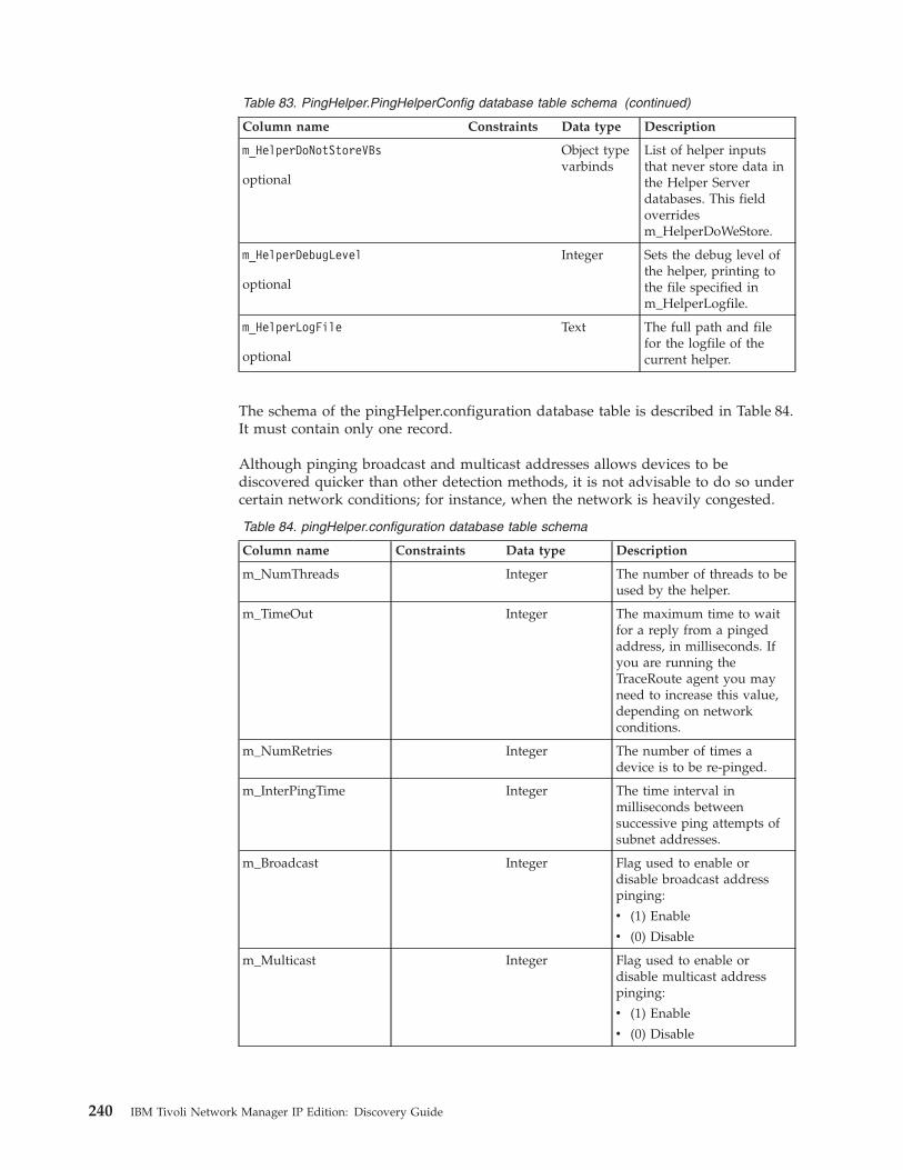
Table 83. PingHelper.PingHelperConfig database table schema (continued)
Column name Constraints Data type Description
m_HelperDoNotStoreVBs
optional
Object typevarbinds
List of helper inputsthat never store data inthe Helper Serverdatabases. This fieldoverridesm_HelperDoWeStore.
m_HelperDebugLevel
optional
Integer Sets the debug level ofthe helper, printing tothe file specified inm_HelperLogfile.
m_HelperLogFile
optional
Text The full path and filefor the logfile of thecurrent helper.
The schema of the pingHelper.configuration database table is described in Table 84.It must contain only one record.
Although pinging broadcast and multicast addresses allows devices to bediscovered quicker than other detection methods, it is not advisable to do so undercertain network conditions; for instance, when the network is heavily congested.
Table 84. pingHelper.configuration database table schema
Column name Constraints Data type Description
m_NumThreads Integer The number of threads to beused by the helper.
m_TimeOut Integer The maximum time to waitfor a reply from a pingedaddress, in milliseconds. Ifyou are running theTraceRoute agent you mayneed to increase this value,depending on networkconditions.
m_NumRetries Integer The number of times adevice is to be re-pinged.
m_InterPingTime Integer The time interval inmilliseconds betweensuccessive ping attempts ofsubnet addresses.
m_Broadcast Integer Flag used to enable ordisable broadcast addresspinging:
v (1) Enable
v (0) Disable
m_Multicast Integer Flag used to enable ordisable multicast addresspinging:
v (1) Enable
v (0) Disable
240 IBM Tivoli Network Manager IP Edition: Discovery Guide
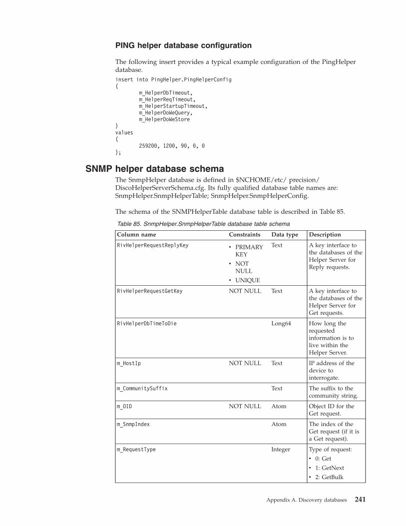
PING helper database configuration
The following insert provides a typical example configuration of the PingHelperdatabase.insert into PingHelper.PingHelperConfig(
m_HelperDbTimeout,m_HelperReqTimeout,m_HelperStartupTimeout,m_HelperDoWeQuery,m_HelperDoWeStore
)values(
259200, 1200, 90, 0, 0);
SNMP helper database schemaThe SnmpHelper database is defined in $NCHOME/etc/ precision/DiscoHelperServerSchema.cfg. Its fully qualified database table names are:SnmpHelper.SnmpHelperTable; SnmpHelper.SnmpHelperConfig.
The schema of the SNMPHelperTable database table is described in Table 85.
Table 85. SnmpHelper.SnmpHelperTable database table schema
Column name Constraints Data type Description
RivHelperRequestReplyKey v PRIMARYKEY
v NOTNULL
v UNIQUE
Text A key interface tothe databases of theHelper Server forReply requests.
RivHelperRequestGetKey NOT NULL Text A key interface tothe databases of theHelper Server forGet requests.
RivHelperDbTimeToDie Long64 How long therequestedinformation is tolive within theHelper Server.
m_HostIp NOT NULL Text IP address of thedevice tointerrogate.
m_CommunitySuffix Text The suffix to thecommunity string.
m_OID NOT NULL Atom Object ID for theGet request.
m_SnmpIndex Atom The index of theGet request (if it isa Get request).
m_RequestType Integer Type of request:
v 0: Get
v 1: GetNext
v 2: GetBulk
Appendix A. Discovery databases 241
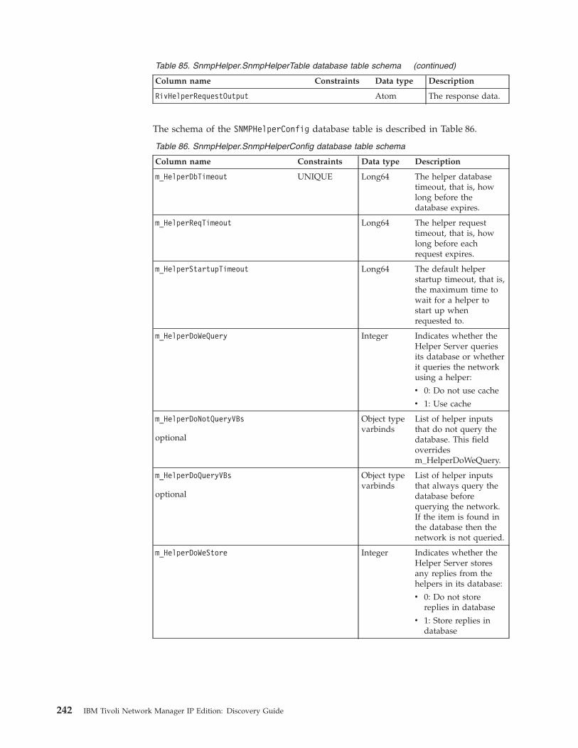
Table 85. SnmpHelper.SnmpHelperTable database table schema (continued)
Column name Constraints Data type Description
RivHelperRequestOutput Atom The response data.
The schema of the SNMPHelperConfig database table is described in Table 86.
Table 86. SnmpHelper.SnmpHelperConfig database table schema
Column name Constraints Data type Description
m_HelperDbTimeout UNIQUE Long64 The helper databasetimeout, that is, howlong before thedatabase expires.
m_HelperReqTimeout Long64 The helper requesttimeout, that is, howlong before eachrequest expires.
m_HelperStartupTimeout Long64 The default helperstartup timeout, that is,the maximum time towait for a helper tostart up whenrequested to.
m_HelperDoWeQuery Integer Indicates whether theHelper Server queriesits database or whetherit queries the networkusing a helper:
v 0: Do not use cache
v 1: Use cache
m_HelperDoNotQueryVBs
optional
Object typevarbinds
List of helper inputsthat do not query thedatabase. This fieldoverridesm_HelperDoWeQuery.
m_HelperDoQueryVBs
optional
Object typevarbinds
List of helper inputsthat always query thedatabase beforequerying the network.If the item is found inthe database then thenetwork is not queried.
m_HelperDoWeStore Integer Indicates whether theHelper Server storesany replies from thehelpers in its database:
v 0: Do not storereplies in database
v 1: Store replies indatabase
242 IBM Tivoli Network Manager IP Edition: Discovery Guide
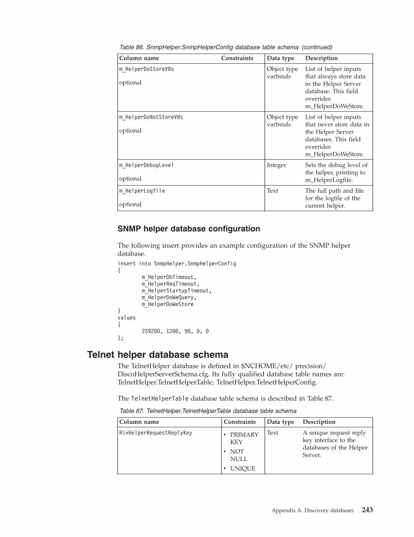
Table 86. SnmpHelper.SnmpHelperConfig database table schema (continued)
Column name Constraints Data type Description
m_HelperDoStoreVBs
optional
Object typevarbinds
List of helper inputsthat always store datain the Helper Serverdatabase. This fieldoverridesm_HelperDoWeStore.
m_HelperDoNotStoreVBs
optional
Object typevarbinds
List of helper inputsthat never store data inthe Helper Serverdatabases. This fieldoverridesm_HelperDoWeStore.
m_HelperDebugLevel
optional
Integer Sets the debug level ofthe helper, printing tom_HelperLogfile.
m_HelperLogfile
optional
Text The full path and filefor the logfile of thecurrent helper.
SNMP helper database configuration
The following insert provides an example configuration of the SNMP helperdatabase.insert into SnmpHelper.SnmpHelperConfig(
m_HelperDbTimeout,m_HelperReqTimeout,m_HelperStartupTimeout,m_HelperDoWeQuery,m_HelperDoWeStore
)values(
259200, 1200, 90, 0, 0);
Telnet helper database schemaThe TelnetHelper database is defined in $NCHOME/etc/ precision/DiscoHelperServerSchema.cfg. Its fully qualified database table names are:TelnetHelper.TelnetHelperTable; TelnetHelper.TelnetHelperConfig.
The TelnetHelperTable database table schema is described in Table 87.
Table 87. TelnetHelper.TelnetHelperTable database table schema
Column name Constraints Data type Description
RivHelperRequestReplyKey v PRIMARYKEY
v NOTNULL
v UNIQUE
Text A unique request replykey interface to thedatabases of the HelperServer.
Appendix A. Discovery databases 243
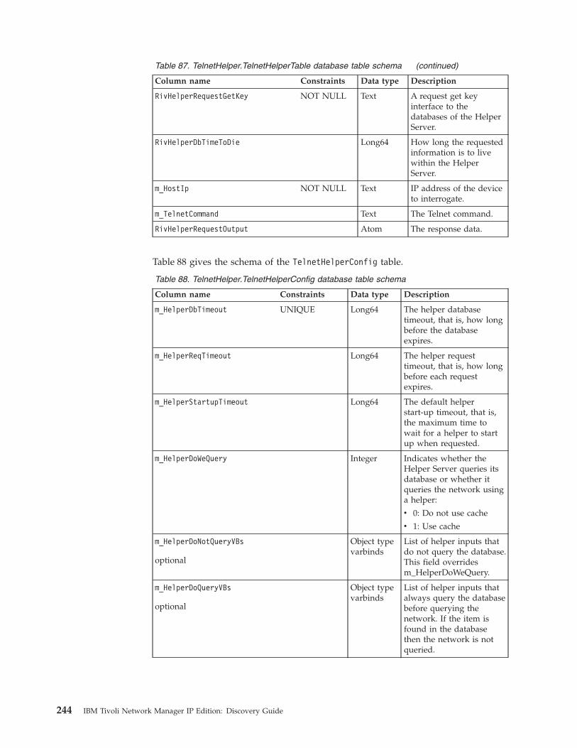
Table 87. TelnetHelper.TelnetHelperTable database table schema (continued)
Column name Constraints Data type Description
RivHelperRequestGetKey NOT NULL Text A request get keyinterface to thedatabases of the HelperServer.
RivHelperDbTimeToDie Long64 How long the requestedinformation is to livewithin the HelperServer.
m_HostIp NOT NULL Text IP address of the deviceto interrogate.
m_TelnetCommand Text The Telnet command.
RivHelperRequestOutput Atom The response data.
Table 88 gives the schema of the TelnetHelperConfig table.
Table 88. TelnetHelper.TelnetHelperConfig database table schema
Column name Constraints Data type Description
m_HelperDbTimeout UNIQUE Long64 The helper databasetimeout, that is, how longbefore the databaseexpires.
m_HelperReqTimeout Long64 The helper requesttimeout, that is, how longbefore each requestexpires.
m_HelperStartupTimeout Long64 The default helperstart-up timeout, that is,the maximum time towait for a helper to startup when requested.
m_HelperDoWeQuery Integer Indicates whether theHelper Server queries itsdatabase or whether itqueries the network usinga helper:
v 0: Do not use cache
v 1: Use cache
m_HelperDoNotQueryVBs
optional
Object typevarbinds
List of helper inputs thatdo not query the database.This field overridesm_HelperDoWeQuery.
m_HelperDoQueryVBs
optional
Object typevarbinds
List of helper inputs thatalways query the databasebefore querying thenetwork. If the item isfound in the databasethen the network is notqueried.
244 IBM Tivoli Network Manager IP Edition: Discovery Guide

Table 88. TelnetHelper.TelnetHelperConfig database table schema (continued)
Column name Constraints Data type Description
m_HelperDoWeStore Integer Indicates whether theHelper Server stores anyreplies from the helpers inits database:
v 0: Do not store repliesin database
v 1: Store replies indatabase
m_HelperDoStoreVBs
optional
Object typevarbinds
List of helper inputs thatalways store data in theHelper Server database.This field overridesm_HelperDoWeStore.
m_HelperDoNotStoreVBs
optional
Object typevarbinds
List of helper inputs thatnever store data in theHelper Server databases.This field overridesm_HelperDoWeStore.
m_HelperDebugLevel
optional
Integer Sets the debug level of thehelper, printing tom_HelperLogfile.
m_HelperLogfile
optional
Text The full path and file forthe logfile of the currenthelper.
Telnet helper database configuration
The following example insert gives a typical configuration of the Telnet helperdatabase.insert into TelnetHelper.TelnetHelperConfig(
m_HelperDbTimeout,m_HelperReqTimeout,m_HelperStartupTimeout,m_HelperDoWeQuery,m_HelperDoWeStore
)values(
259200, 1200, 90, 0, 0);
XMLRPC helper database schemaThe XmlRpcHelper helper database is defined in $NCHOME/etc/precision/DiscoHelperServerSchema.cfg. Its fully qualified database table names are:XmlRpcHelper.XmlRpcHelperTable; XmlRpcHelper.XmlRpcHelperConfig.
The schema of the XmlRpcHelper.XmlRpcHelperTable database table is describedin Table 89 on page 246.
Appendix A. Discovery databases 245
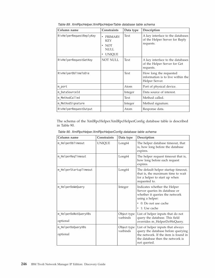
Table 89. XmlRpcHelper.XmlRpcHelperTable database table schema
Column name Constraints Data type Description
RivHelperRequestReplyKey v PRIMARYKEY
v NOTNULL
v UNIQUE
Text A key interface to the databasesof the Helper Server for Replyrequests.
RivHelperRequestGetKey NOT NULL Text A key interface to the databasesof the Helper Server for Getrequests.
RivHelperDbTimeToDie Text How long the requestedinformation is to live within theHelper Server.
m_port Atom Port of physical device.
m_DataSourceId Integer Data source of interest.
m_MethodCalled Text Method called.
m_MethodSignature Integer Method signature.
RivHelperRequestOutput Atom Response data.
The schema of the XmlRpcHelper.XmlRpcHelperConfig database table is describedin Table 90.
Table 90. XmlRpcHelper.XmlRpcHelperConfig database table schema
Column name Constraints Data type Description
m_HelperDbTimeout UNIQUE Long64 The helper database timeout, thatis, how long before the databaseexpires.
m_HelperReqTimeout Long64 The helper request timeout that is,how long before each requestexpires.
m_HelperStartupTimeout Long64 The default helper startup timeout,that is, the maximum time to waitfor a helper to start up whenrequested to.
m_HelperDoWeQuery Integer Indicates whether the HelperServer queries its database orwhether it queries the networkusing a helper:
v 0: Do not use cache
v 1: Use cache
m_HelperDoNotQueryVBs
optional
Object typevarbinds
List of helper inputs that do notquery the database. This fieldoverrides m_HelperDoWeQuery.
m_HelperDoQueryVBs
optional
Object typevarbinds
List of helper inputs that alwaysquery the database before queryingthe network. If the item is found inthe database then the network isnot queried.
246 IBM Tivoli Network Manager IP Edition: Discovery Guide
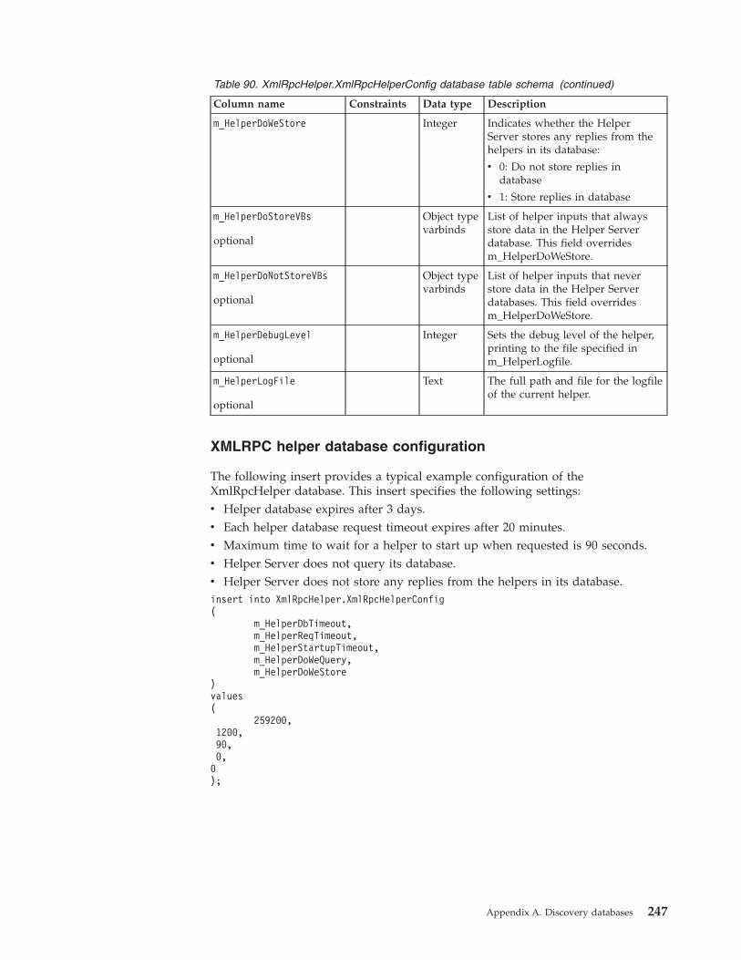
Table 90. XmlRpcHelper.XmlRpcHelperConfig database table schema (continued)
Column name Constraints Data type Description
m_HelperDoWeStore Integer Indicates whether the HelperServer stores any replies from thehelpers in its database:
v 0: Do not store replies indatabase
v 1: Store replies in database
m_HelperDoStoreVBs
optional
Object typevarbinds
List of helper inputs that alwaysstore data in the Helper Serverdatabase. This field overridesm_HelperDoWeStore.
m_HelperDoNotStoreVBs
optional
Object typevarbinds
List of helper inputs that neverstore data in the Helper Serverdatabases. This field overridesm_HelperDoWeStore.
m_HelperDebugLevel
optional
Integer Sets the debug level of the helper,printing to the file specified inm_HelperLogfile.
m_HelperLogFile
optional
Text The full path and file for the logfileof the current helper.
XMLRPC helper database configuration
The following insert provides a typical example configuration of theXmlRpcHelper database. This insert specifies the following settings:v Helper database expires after 3 days.v Each helper database request timeout expires after 20 minutes.v Maximum time to wait for a helper to start up when requested is 90 seconds.v Helper Server does not query its database.v Helper Server does not store any replies from the helpers in its database.insert into XmlRpcHelper.XmlRpcHelperConfig(
m_HelperDbTimeout,m_HelperReqTimeout,m_HelperStartupTimeout,m_HelperDoWeQuery,m_HelperDoWeStore
)values(
259200,1200,90,0,0);
Appendix A. Discovery databases 247
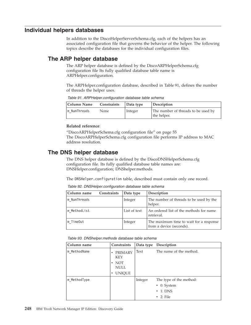
Individual helpers databasesIn addition to the DiscoHelperServerSchema.cfg, each of the helpers has anassociated configuration file that governs the behavior of the helper. The followingtopics describe the databases for the individual configuration files.
The ARP helper databaseThe ARP helper database is defined by the DiscoARPHelperSchema.cfgconfiguration file Its fully qualified database table name isARPHelper.configuration.
The ARPHelper.configuration database, described in Table 91, defines the numberof threads the helper uses.
Table 91. ARPHelper.configuration database table schema
Column Name Constraints Data type Description
m_NumThreads None Integer The number of threads to be used bythe helper.
Related reference:“DiscoARPHelperSchema.cfg configuration file” on page 55The DiscoARPHelperSchema.cfg configuration file performs IP address to MACaddress resolution.
The DNS helper databaseThe DNS helper database is defined by the DiscoDNSHelperSchema.cfgconfiguration file. Its fully qualified database table names are:DNSHelper.configuration; DNShelper.methods.
The DNSHelper.configuration table, described must contain only one record.
Table 92. DNSHelper.configuration database table schema
Column name Constraints Data type Description
m_NumThreads Integer The number of threads to be used by thehelper.
m_MethodList List of text An ordered list of the methods for nameretrieval.
m_TimeOut Integer The maximum time to wait for a responsefrom a device (seconds).
Table 93. DNShelper.methods database table schema
Column name Constraints Data type Description
m_MethodName v PRIMARYKEY
v NOTNULL
v UNIQUE
Text The name of the method.
m_MethodType Integer The type of the method:
v 0: System
v 1: DNS
v 2: File
248 IBM Tivoli Network Manager IP Edition: Discovery Guide
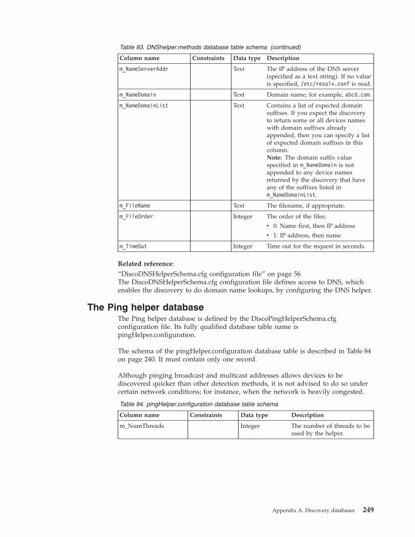
Table 93. DNShelper.methods database table schema (continued)
Column name Constraints Data type Description
m_NameServerAddr Text The IP address of the DNS server(specified as a text string). If no valueis specified, /etc/resolv.conf is read.
m_NameDomain Text Domain name; for example, abcd.com.
m_NameDomainList Text Contains a list of expected domainsuffixes. If you expect the discoveryto return some or all devices nameswith domain suffixes alreadyappended, then you can specify a listof expected domain suffixes in thiscolumn.Note: The domain suffix valuespecified in m_NameDomain is notappended to any device namesreturned by the discovery that haveany of the suffixes listed inm_NameDomainList.
m_FileName Text The filename, if appropriate.
m_FileOrder Integer The order of the files:
v 0: Name first, then IP address
v 1: IP address, then name
m_TimeOut Integer Time out for the request in seconds.
Related reference:“DiscoDNSHelperSchema.cfg configuration file” on page 56The DiscoDNSHelperSchema.cfg configuration file defines access to DNS, whichenables the discovery to do domain name lookups, by configuring the DNS helper.
The Ping helper databaseThe Ping helper database is defined by the DiscoPingHelperSchema.cfgconfiguration file. Its fully qualified database table name ispingHelper.configuration.
The schema of the pingHelper.configuration database table is described in Table 84on page 240. It must contain only one record.
Although pinging broadcast and multicast addresses allows devices to bediscovered quicker than other detection methods, it is not advised to do so undercertain network conditions; for instance, when the network is heavily congested.
Table 94. pingHelper.configuration database table schema
Column name Constraints Data type Description
m_NumThreads Integer The number of threads to beused by the helper.
Appendix A. Discovery databases 249
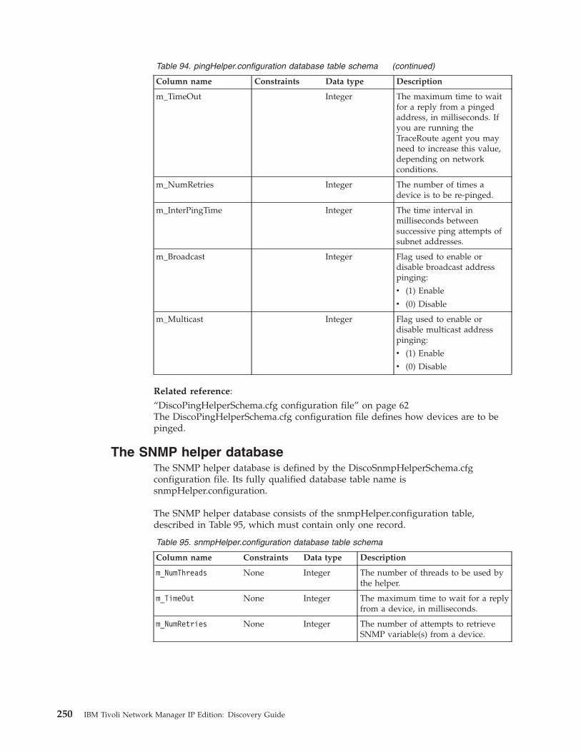
Table 94. pingHelper.configuration database table schema (continued)
Column name Constraints Data type Description
m_TimeOut Integer The maximum time to waitfor a reply from a pingedaddress, in milliseconds. Ifyou are running theTraceRoute agent you mayneed to increase this value,depending on networkconditions.
m_NumRetries Integer The number of times adevice is to be re-pinged.
m_InterPingTime Integer The time interval inmilliseconds betweensuccessive ping attempts ofsubnet addresses.
m_Broadcast Integer Flag used to enable ordisable broadcast addresspinging:
v (1) Enable
v (0) Disable
m_Multicast Integer Flag used to enable ordisable multicast addresspinging:
v (1) Enable
v (0) Disable
Related reference:“DiscoPingHelperSchema.cfg configuration file” on page 62The DiscoPingHelperSchema.cfg configuration file defines how devices are to bepinged.
The SNMP helper databaseThe SNMP helper database is defined by the DiscoSnmpHelperSchema.cfgconfiguration file. Its fully qualified database table name issnmpHelper.configuration.
The SNMP helper database consists of the snmpHelper.configuration table,described in Table 95, which must contain only one record.
Table 95. snmpHelper.configuration database table schema
Column name Constraints Data type Description
m_NumThreads None Integer The number of threads to be used bythe helper.
m_TimeOut None Integer The maximum time to wait for a replyfrom a device, in milliseconds.
m_NumRetries None Integer The number of attempts to retrieveSNMP variable(s) from a device.
250 IBM Tivoli Network Manager IP Edition: Discovery Guide
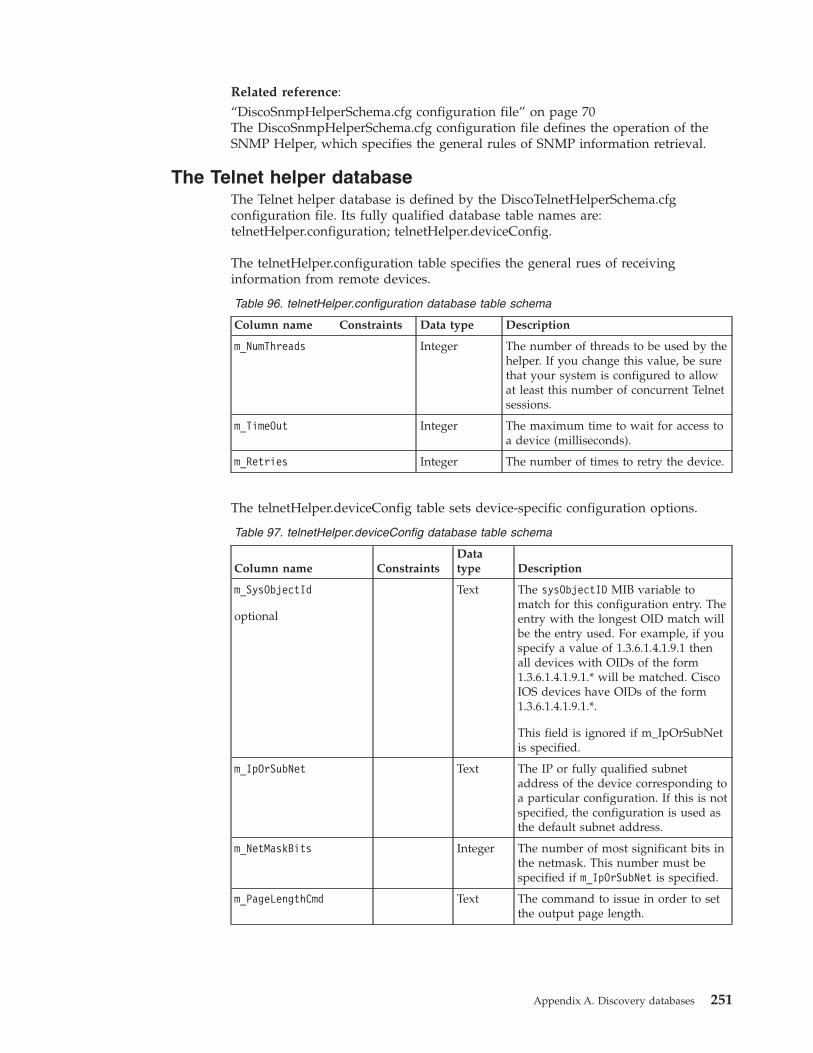
Related reference:“DiscoSnmpHelperSchema.cfg configuration file” on page 70The DiscoSnmpHelperSchema.cfg configuration file defines the operation of theSNMP Helper, which specifies the general rules of SNMP information retrieval.
The Telnet helper databaseThe Telnet helper database is defined by the DiscoTelnetHelperSchema.cfgconfiguration file. Its fully qualified database table names are:telnetHelper.configuration; telnetHelper.deviceConfig.
The telnetHelper.configuration table specifies the general rues of receivinginformation from remote devices.
Table 96. telnetHelper.configuration database table schema
Column name Constraints Data type Description
m_NumThreads Integer The number of threads to be used by thehelper. If you change this value, be surethat your system is configured to allowat least this number of concurrent Telnetsessions.
m_TimeOut Integer The maximum time to wait for access toa device (milliseconds).
m_Retries Integer The number of times to retry the device.
The telnetHelper.deviceConfig table sets device-specific configuration options.
Table 97. telnetHelper.deviceConfig database table schema
Column name ConstraintsDatatype Description
m_SysObjectId
optional
Text The sysObjectID MIB variable tomatch for this configuration entry. Theentry with the longest OID match willbe the entry used. For example, if youspecify a value of 1.3.6.1.4.1.9.1 thenall devices with OIDs of the form1.3.6.1.4.1.9.1.* will be matched. CiscoIOS devices have OIDs of the form1.3.6.1.4.1.9.1.*.
This field is ignored if m_IpOrSubNetis specified.
m_IpOrSubNet Text The IP or fully qualified subnetaddress of the device corresponding toa particular configuration. If this is notspecified, the configuration is used asthe default subnet address.
m_NetMaskBits Integer The number of most significant bits inthe netmask. This number must bespecified if m_IpOrSubNet is specified.
m_PageLengthCmd Text The command to issue in order to setthe output page length.
Appendix A. Discovery databases 251

Table 97. telnetHelper.deviceConfig database table schema (continued)
Column name ConstraintsDatatype Description
m_PageLength Integer The output page length size. This isset to 0 by default; that is, no paging.
If you set a page length size, you mustalso insert a value into them_PageLengthCmd column in order toset a page length command.
m_ContinueMsg Text The expected prompt from the remotedevice between paged output; forexample, "Do you want to continue".Regular expressions are valid entries.
m_ContinueCmd Text The response to send to the remotedevice in order for it to continue thepaged output. This is usually set to"y".
You must take care setting this value,as some devices require a carriagereturn after the command and somedo not. For maximum flexibility, areturn is not added by default. It mustbe specified explicitly using a trailingCtrl-M in the string.
m_TransmissionDelay Integer This option allows you to customizethe delay used by ncp_dh_telnet whentransmitting data to a device. Thismay be useful if data loss or deviceissues occur when using the defaulttransmission delay setting.
Related reference:“DiscoTelnetHelperSchema.cfg configuration file” on page 71The DiscoTelnetHelperSchema.cfg configuration file defines the operation of theTelnet helper, which returns the results of a Telnet operation into a specifieddevice.
The XMLRPC helper databaseThe XMLRPC helper database is defined by the DiscoXmlRpcHelperSchema.cfgconfiguration file. Its fully qualified database table name isxmlRpcHelper.configuration.
The schema of the xmlRpcHelper.configuration database table is described inTable 98. It must contain only one record.
Table 98. xmlRpcHelper.configuration database table schema
Column name Constraints Data type Description
m_NumThreads None Integer The number of threads to be usedby the helper.
252 IBM Tivoli Network Manager IP Edition: Discovery Guide
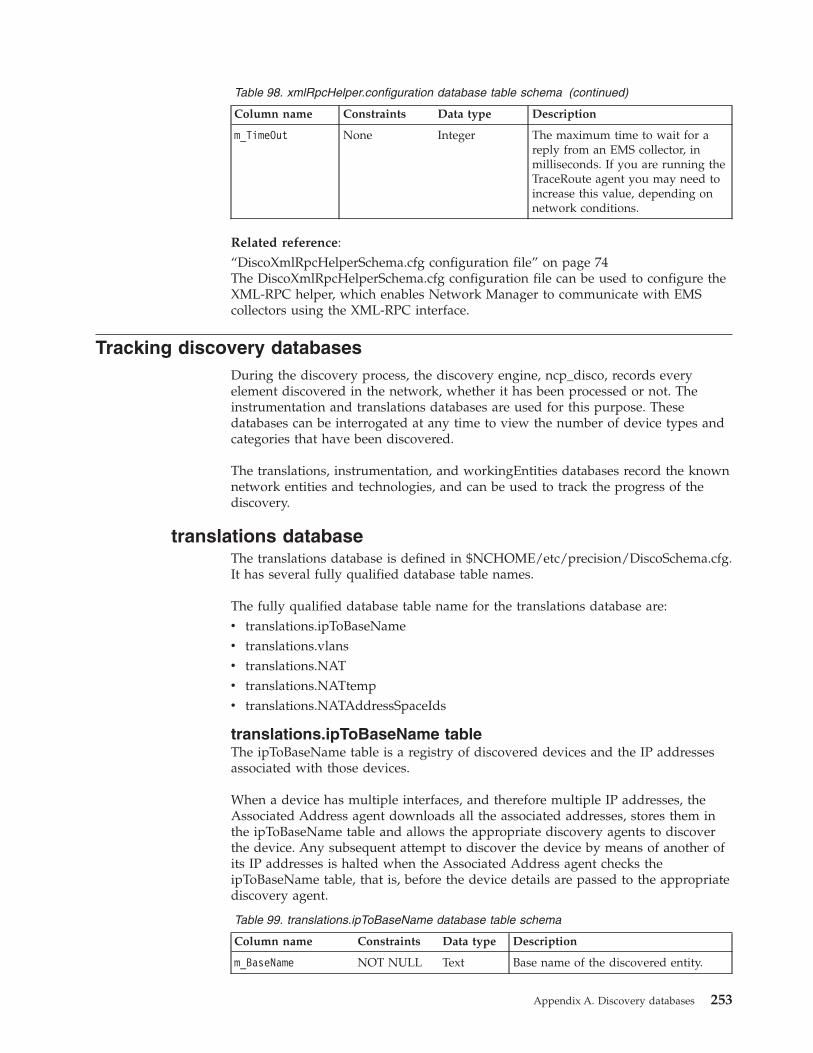
Table 98. xmlRpcHelper.configuration database table schema (continued)
Column name Constraints Data type Description
m_TimeOut None Integer The maximum time to wait for areply from an EMS collector, inmilliseconds. If you are running theTraceRoute agent you may need toincrease this value, depending onnetwork conditions.
Related reference:“DiscoXmlRpcHelperSchema.cfg configuration file” on page 74The DiscoXmlRpcHelperSchema.cfg configuration file can be used to configure theXML-RPC helper, which enables Network Manager to communicate with EMScollectors using the XML-RPC interface.
Tracking discovery databasesDuring the discovery process, the discovery engine, ncp_disco, records everyelement discovered in the network, whether it has been processed or not. Theinstrumentation and translations databases are used for this purpose. Thesedatabases can be interrogated at any time to view the number of device types andcategories that have been discovered.
The translations, instrumentation, and workingEntities databases record the knownnetwork entities and technologies, and can be used to track the progress of thediscovery.
translations databaseThe translations database is defined in $NCHOME/etc/precision/DiscoSchema.cfg.It has several fully qualified database table names.
The fully qualified database table name for the translations database are:v translations.ipToBaseNamev translations.vlansv translations.NATv translations.NATtempv translations.NATAddressSpaceIds
translations.ipToBaseName tableThe ipToBaseName table is a registry of discovered devices and the IP addressesassociated with those devices.
When a device has multiple interfaces, and therefore multiple IP addresses, theAssociated Address agent downloads all the associated addresses, stores them inthe ipToBaseName table and allows the appropriate discovery agents to discoverthe device. Any subsequent attempt to discover the device by means of another ofits IP addresses is halted when the Associated Address agent checks theipToBaseName table, that is, before the device details are passed to the appropriatediscovery agent.
Table 99. translations.ipToBaseName database table schema
Column name Constraints Data type Description
m_BaseName NOT NULL Text Base name of the discovered entity.
Appendix A. Discovery databases 253
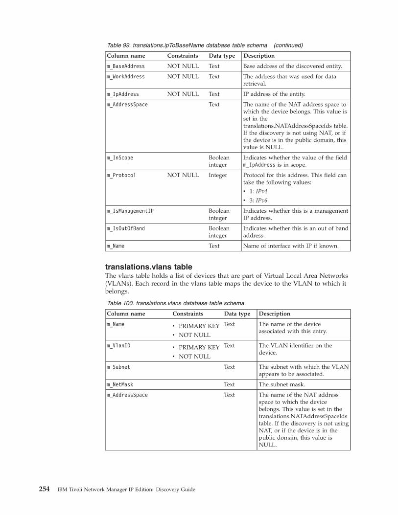
Table 99. translations.ipToBaseName database table schema (continued)
Column name Constraints Data type Description
m_BaseAddress NOT NULL Text Base address of the discovered entity.
m_WorkAddress NOT NULL Text The address that was used for dataretrieval.
m_IpAddress NOT NULL Text IP address of the entity.
m_AddressSpace Text The name of the NAT address space towhich the device belongs. This value isset in thetranslations.NATAddressSpaceIds table.If the discovery is not using NAT, or ifthe device is in the public domain, thisvalue is NULL.
m_InScope Booleaninteger
Indicates whether the value of the fieldm_IpAddress is in scope.
m_Protocol NOT NULL Integer Protocol for this address. This field cantake the following values:
v 1: IPv4
v 3: IPv6
m_IsManagementIP Booleaninteger
Indicates whether this is a managementIP address.
m_IsOutOfBand Booleaninteger
Indicates whether this is an out of bandaddress.
m_Name Text Name of interface with IP if known.
translations.vlans tableThe vlans table holds a list of devices that are part of Virtual Local Area Networks(VLANs). Each record in the vlans table maps the device to the VLAN to which itbelongs.
Table 100. translations.vlans database table schema
Column name Constraints Data type Description
m_Name v PRIMARY KEY
v NOT NULL
Text The name of the deviceassociated with this entry.
m_VlanID v PRIMARY KEY
v NOT NULL
Text The VLAN identifier on thedevice.
m_Subnet Text The subnet with which the VLANappears to be associated.
m_NetMask Text The subnet mask.
m_AddressSpace Text The name of the NAT addressspace to which the devicebelongs. This value is set in thetranslations.NATAddressSpaceIdstable. If the discovery is not usingNAT, or if the device is in thepublic domain, this value isNULL.
254 IBM Tivoli Network Manager IP Edition: Discovery Guide

translations.NAT tableThe NAT table is used to hold static NAT mappings. The mapped devices arediscovered even if they are outside the scope of the discovery.
Table 101. translations.NAT database table schema
Column name ConstraintsDatatype Description
m_OutsideGlobalAddr v PRIMARY KEY
v NOT NULL
Text The public address.
m_InsideLocalAddr NOT NULL Text The private address.
m_InsideGlobalAddr Text This column is currently not used.
m_OutsideLocalAddr Text This column is currently not used.
m_AddressSpace Text The name of the NAT address spaceto which the device belongs. Thisvalue is set in thetranslations.NATAddressSpaceIdstable. If the discovery is not usingNAT, or if the device is in the publicdomain, this value is NULL.
translations.NATtempThe NATtemp table is used to hold NAT mappings from a particular NATgateway. This enables the discovery process to compare the old and new NATmappings and initiate a partial or full rediscovery if necessary.
Table 102. translations.NATtemp database table schema
Column name Constraints Data type Description
m_OutsideAddr v PRIMARYKEY
v NOT NULL
Text The public address of the device.
m_InsideAddr NOT NULL Text The private address of the device.
m_AddressSpace Text The name of the NAT address spaceto which the device belongs. Thisvalue is set in thetranslations.NATAddressSpaceIdstable. If the discovery is not usingNAT, or if the device is in the publicdomain, this value is NULL.
translations.NATAddressSpaceIds tableThe NATAddressSpaceIds table is used to identify the IP addresses of NATgateways and specify an address-space identifier for each one.
Table 103. translations.NATAddressSpaceIds database table schema
Column name Constraints Data type Description
m_NATGatewayIP v PRIMARYKEY
v NOT NULL
Text The IP address of the gateway.
Appendix A. Discovery databases 255
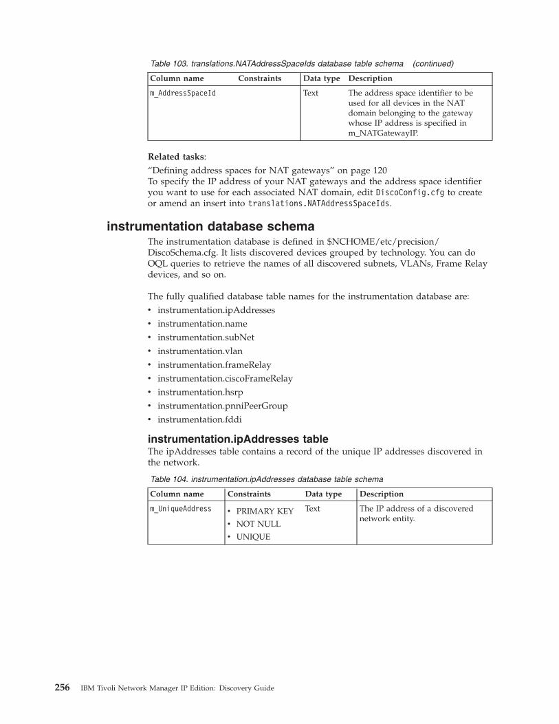
Table 103. translations.NATAddressSpaceIds database table schema (continued)
Column name Constraints Data type Description
m_AddressSpaceId Text The address space identifier to beused for all devices in the NATdomain belonging to the gatewaywhose IP address is specified inm_NATGatewayIP.
Related tasks:“Defining address spaces for NAT gateways” on page 120To specify the IP address of your NAT gateways and the address space identifieryou want to use for each associated NAT domain, edit DiscoConfig.cfg to createor amend an insert into translations.NATAddressSpaceIds.
instrumentation database schemaThe instrumentation database is defined in $NCHOME/etc/precision/DiscoSchema.cfg. It lists discovered devices grouped by technology. You can doOQL queries to retrieve the names of all discovered subnets, VLANs, Frame Relaydevices, and so on.
The fully qualified database table names for the instrumentation database are:v instrumentation.ipAddressesv instrumentation.namev instrumentation.subNetv instrumentation.vlanv instrumentation.frameRelayv instrumentation.ciscoFrameRelayv instrumentation.hsrpv instrumentation.pnniPeerGroupv instrumentation.fddi
instrumentation.ipAddresses tableThe ipAddresses table contains a record of the unique IP addresses discovered inthe network.
Table 104. instrumentation.ipAddresses database table schema
Column name Constraints Data type Description
m_UniqueAddress v PRIMARY KEY
v NOT NULL
v UNIQUE
Text The IP address of a discoverednetwork entity.
256 IBM Tivoli Network Manager IP Edition: Discovery Guide
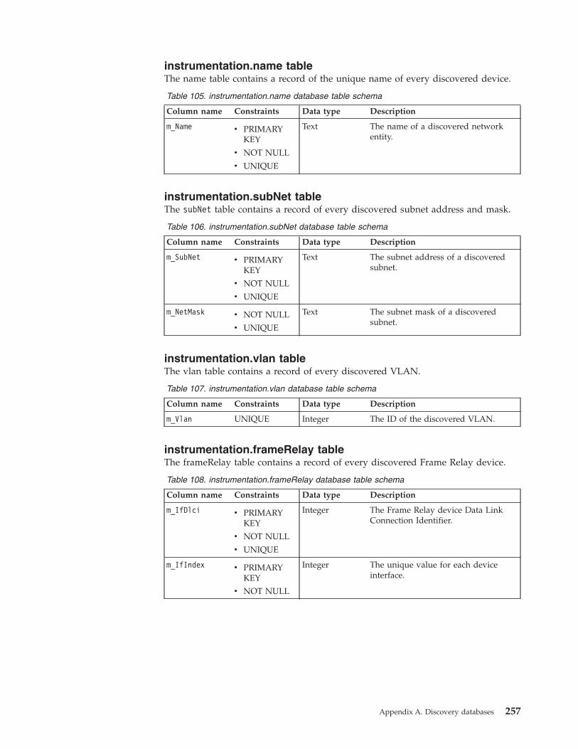
instrumentation.name tableThe name table contains a record of the unique name of every discovered device.
Table 105. instrumentation.name database table schema
Column name Constraints Data type Description
m_Name v PRIMARYKEY
v NOT NULL
v UNIQUE
Text The name of a discovered networkentity.
instrumentation.subNet tableThe subNet table contains a record of every discovered subnet address and mask.
Table 106. instrumentation.subNet database table schema
Column name Constraints Data type Description
m_SubNet v PRIMARYKEY
v NOT NULL
v UNIQUE
Text The subnet address of a discoveredsubnet.
m_NetMask v NOT NULL
v UNIQUE
Text The subnet mask of a discoveredsubnet.
instrumentation.vlan tableThe vlan table contains a record of every discovered VLAN.
Table 107. instrumentation.vlan database table schema
Column name Constraints Data type Description
m_Vlan UNIQUE Integer The ID of the discovered VLAN.
instrumentation.frameRelay tableThe frameRelay table contains a record of every discovered Frame Relay device.
Table 108. instrumentation.frameRelay database table schema
Column name Constraints Data type Description
m_IfDlci v PRIMARYKEY
v NOT NULL
v UNIQUE
Integer The Frame Relay device Data LinkConnection Identifier.
m_IfIndex v PRIMARYKEY
v NOT NULL
Integer The unique value for each deviceinterface.
Appendix A. Discovery databases 257
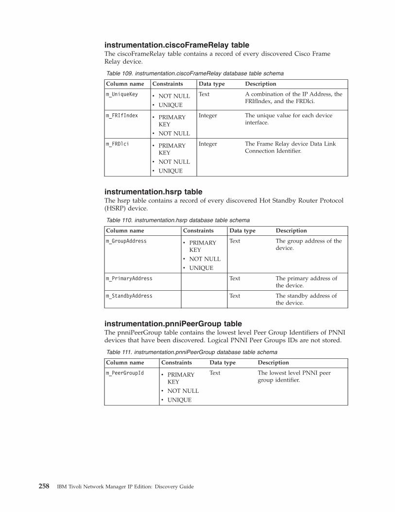
instrumentation.ciscoFrameRelay tableThe ciscoFrameRelay table contains a record of every discovered Cisco FrameRelay device.
Table 109. instrumentation.ciscoFrameRelay database table schema
Column name Constraints Data type Description
m_UniqueKey v NOT NULL
v UNIQUE
Text A combination of the IP Address, theFRIfIndex, and the FRDlci.
m_FRIfIndex v PRIMARYKEY
v NOT NULL
Integer The unique value for each deviceinterface.
m_FRDlci v PRIMARYKEY
v NOT NULL
v UNIQUE
Integer The Frame Relay device Data LinkConnection Identifier.
instrumentation.hsrp tableThe hsrp table contains a record of every discovered Hot Standby Router Protocol(HSRP) device.
Table 110. instrumentation.hsrp database table schema
Column name Constraints Data type Description
m_GroupAddress v PRIMARYKEY
v NOT NULL
v UNIQUE
Text The group address of thedevice.
m_PrimaryAddress Text The primary address ofthe device.
m_StandbyAddress Text The standby address ofthe device.
instrumentation.pnniPeerGroup tableThe pnniPeerGroup table contains the lowest level Peer Group Identifiers of PNNIdevices that have been discovered. Logical PNNI Peer Groups IDs are not stored.
Table 111. instrumentation.pnniPeerGroup database table schema
Column name Constraints Data type Description
m_PeerGroupId v PRIMARYKEY
v NOT NULL
v UNIQUE
Text The lowest level PNNI peergroup identifier.
258 IBM Tivoli Network Manager IP Edition: Discovery Guide
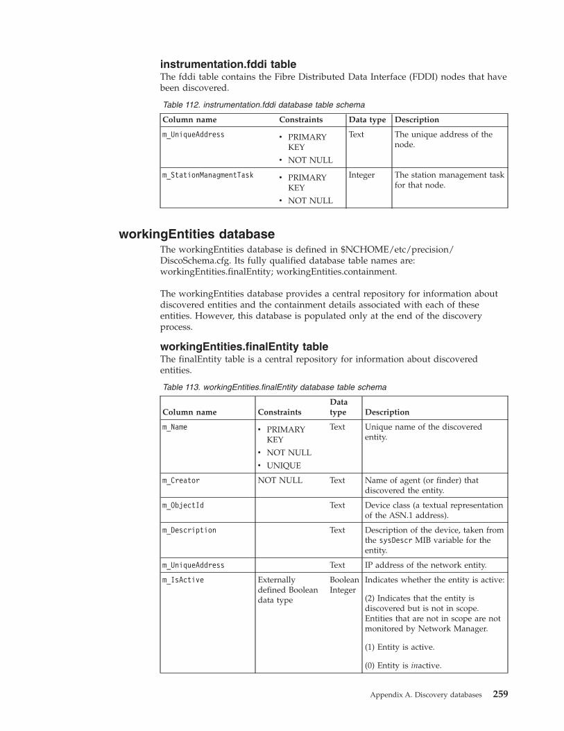
instrumentation.fddi tableThe fddi table contains the Fibre Distributed Data Interface (FDDI) nodes that havebeen discovered.
Table 112. instrumentation.fddi database table schema
Column name Constraints Data type Description
m_UniqueAddress v PRIMARYKEY
v NOT NULL
Text The unique address of thenode.
m_StationManagmentTask v PRIMARYKEY
v NOT NULL
Integer The station management taskfor that node.
workingEntities databaseThe workingEntities database is defined in $NCHOME/etc/precision/DiscoSchema.cfg. Its fully qualified database table names are:workingEntities.finalEntity; workingEntities.containment.
The workingEntities database provides a central repository for information aboutdiscovered entities and the containment details associated with each of theseentities. However, this database is populated only at the end of the discoveryprocess.
workingEntities.finalEntity tableThe finalEntity table is a central repository for information about discoveredentities.
Table 113. workingEntities.finalEntity database table schema
Column name ConstraintsDatatype Description
m_Name v PRIMARYKEY
v NOT NULL
v UNIQUE
Text Unique name of the discoveredentity.
m_Creator NOT NULL Text Name of agent (or finder) thatdiscovered the entity.
m_ObjectId Text Device class (a textual representationof the ASN.1 address).
m_Description Text Description of the device, taken fromthe sysDescr MIB variable for theentity.
m_UniqueAddress Text IP address of the network entity.
m_IsActive Externallydefined Booleandata type
BooleanInteger
Indicates whether the entity is active:
(2) Indicates that the entity isdiscovered but is not in scope.Entities that are not in scope are notmonitored by Network Manager.
(1) Entity is active.
(0) Entity is inactive.
Appendix A. Discovery databases 259

Table 113. workingEntities.finalEntity database table schema (continued)
Column name ConstraintsDatatype Description
m_HaveAccess Externallydefined Booleandata type
Booleaninteger
Flag indicating whether SNMP accessto the device is available:
v 1: SNMP access is available
v 0: No SNMP Access
m_EntityType ExternallydefinedentityType datatype
Integer Element type description of thediscovered entity:
v 0: Unknown type
v 1: Base entity
v 2: Local neighbor
v 3: Remote neighbor
m_BaseName Text The name of the Base Entity for thisdevice.
m_AddressSpace Text The name of the NAT address spaceto which the device belongs. Thisvalue is set in thetranslations.NATAddressSpaceIdstable. If the discovery is not usingNAT, or if the device is in the publicdomain, this value is NULL.
m_ExtraInfo Externallydefined vblistdata type
Object Extra information requested by theagent.
m_LocalNbr Externallydefined vblistdata type
Object Information about the local neighbor.
workingEntities.containment tableThe containment table is a central repository for information about containmentinformation for discovered entities. It shows the containment relationships betweenall entities in the finalEntity table.
As an example of how the containment table works, assume the finalEntity tableincludes the following distinct entities:v A device with IP address 1.2.3.4
v An interface on this device, 1.2.3.4[0[1]]
The finalEntity table provides no containment information for these two entities. Inother words, it does not indicate that the interface 1.2.3.4[0[1]] is physicallycontained within the device 1.2.3.4. This containment information is held withinthe containment table, as follows:m_Container=’1.2.3.4’m_Part=’1.2.3.4[0[1]]’m_IsPhysical=1m_LinkType=1
Note that m_Container and m_Part are each unique names of entities on thenetwork, each with a unique m_Name in the finalEntity table.
260 IBM Tivoli Network Manager IP Edition: Discovery Guide
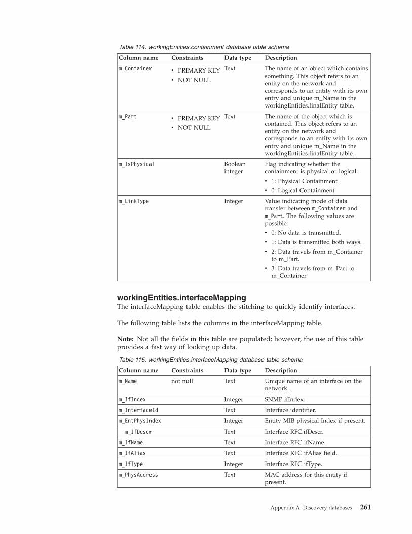
Table 114. workingEntities.containment database table schema
Column name Constraints Data type Description
m_Container v PRIMARY KEY
v NOT NULL
Text The name of an object which containssomething. This object refers to anentity on the network andcorresponds to an entity with its ownentry and unique m_Name in theworkingEntities.finalEntity table.
m_Part v PRIMARY KEY
v NOT NULL
Text The name of the object which iscontained. This object refers to anentity on the network andcorresponds to an entity with its ownentry and unique m_Name in theworkingEntities.finalEntity table.
m_IsPhysical Booleaninteger
Flag indicating whether thecontainment is physical or logical:
v 1: Physical Containment
v 0: Logical Containment
m_LinkType Integer Value indicating mode of datatransfer between m_Container andm_Part. The following values arepossible:
v 0: No data is transmitted.
v 1: Data is transmitted both ways.
v 2: Data travels from m_Containerto m_Part.
v 3: Data travels from m_Part tom_Container
workingEntities.interfaceMappingThe interfaceMapping table enables the stitching to quickly identify interfaces.
The following table lists the columns in the interfaceMapping table.
Note: Not all the fields in this table are populated; however, the use of this tableprovides a fast way of looking up data.
Table 115. workingEntities.interfaceMapping database table schema
Column name Constraints Data type Description
m_Name not null Text Unique name of an interface on thenetwork.
m_IfIndex Integer SNMP ifIndex.
m_InterfaceId Text Interface identifier.
m_EntPhysIndex Integer Entity MIB physical Index if present.
m_IfDescr Text Interface RFC.ifDescr.
m_IfName Text Interface RFC ifName.
m_IfAlias Text Interface RFC ifAlias field.
m_IfType Integer Interface RFC ifType.
m_PhysAddress Text MAC address for this entity ifpresent.
Appendix A. Discovery databases 261
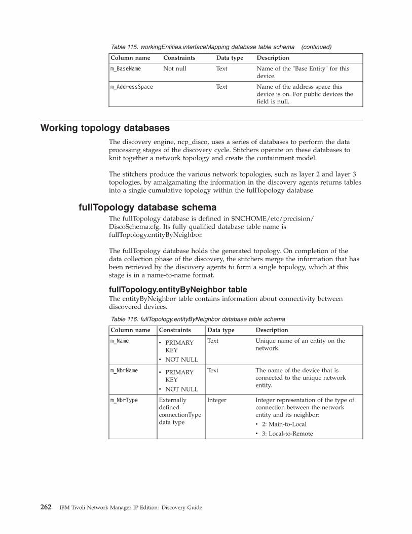
Table 115. workingEntities.interfaceMapping database table schema (continued)
Column name Constraints Data type Description
m_BaseName Not null Text Name of the "Base Entity" for thisdevice.
m_AddressSpace Text Name of the address space thisdevice is on. For public devices thefield is null.
Working topology databasesThe discovery engine, ncp_disco, uses a series of databases to perform the dataprocessing stages of the discovery cycle. Stitchers operate on these databases toknit together a network topology and create the containment model.
The stitchers produce the various network topologies, such as layer 2 and layer 3topologies, by amalgamating the information in the discovery agents returns tablesinto a single cumulative topology within the fullTopology database.
fullTopology database schemaThe fullTopology database is defined in $NCHOME/etc/precision/DiscoSchema.cfg. Its fully qualified database table name isfullTopology.entityByNeighbor.
The fullTopology database holds the generated topology. On completion of thedata collection phase of the discovery, the stitchers merge the information that hasbeen retrieved by the discovery agents to form a single topology, which at thisstage is in a name-to-name format.
fullTopology.entityByNeighbor tableThe entityByNeighbor table contains information about connectivity betweendiscovered devices.
Table 116. fullTopology.entityByNeighbor database table schema
Column name Constraints Data type Description
m_Name v PRIMARYKEY
v NOT NULL
Text Unique name of an entity on thenetwork.
m_NbrName v PRIMARYKEY
v NOT NULL
Text The name of the device that isconnected to the unique networkentity.
m_NbrType ExternallydefinedconnectionTypedata type
Integer Integer representation of the type ofconnection between the networkentity and its neighbor:
v 2: Main-to-Local
v 3: Local-to-Remote
262 IBM Tivoli Network Manager IP Edition: Discovery Guide
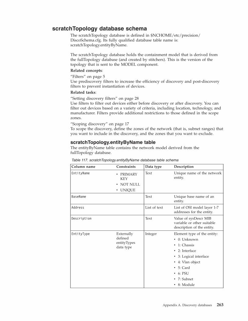
scratchTopology database schemaThe scratchTopology database is defined in $NCHOME/etc/precision/DiscoSchema.cfg. Its fully qualified database table name is:scratchTopology.entityByName.
The scratchTopology database holds the containment model that is derived fromthe fullTopology database (and created by stitchers). This is the version of thetopology that is sent to the MODEL component.Related concepts:“Filters” on page 5Use prediscovery filters to increase the efficiency of discovery and post-discoveryfilters to prevent instantiation of devices.Related tasks:“Setting discovery filters” on page 28Use filters to filter out devices either before discovery or after discovery. You canfilter out devices based on a variety of criteria, including location, technology, andmanufacturer. Filters provide additional restrictions to those defined in the scopezones.“Scoping discovery” on page 17To scope the discovery, define the zones of the network (that is, subnet ranges) thatyou want to include in the discovery, and the zones that you want to exclude.
scratchTopology.entityByName tableThe entityByName table contains the network model derived from thefullTopology database.
Table 117. scratchTopology.entityByName database table schema
Column name Constraints Data type Description
EntityName v PRIMARYKEY
v NOT NULL
v UNIQUE
Text Unique name of the networkentity.
BaseName Text Unique base name of anentity.
Address List of text List of OSI model layer 1-7addresses for the entity.
Description Text Value of sysDescr MIBvariable or other suitabledescription of the entity.
EntityType ExternallydefinedentityTypesdata type
Integer Element type of the entity:
v 0: Unknown
v 1: Chassis
v 2: Interface
v 3: Logical interface
v 4: Vlan object
v 5: Card
v 6: PSU
v 7: Subnet
v 8: Module
Appendix A. Discovery databases 263

Table 117. scratchTopology.entityByName database table schema (continued)
Column name Constraints Data type Description
EntityOID Text The device class to which thenetwork entity belongs. Thisis a textual representation ofthe ASN.1 address.
Status ExternallydefinedBoolean datatype
Boolean integer Flag indicating the state ofthe entity:
v 1: Active
v 0: Not Active
IsActive ExternallydefinedBoolean datatype
Boolean integer Flag indicating whether ornot the entity is active:
v 1: Active
v 0: Not Active
Contains List of text List of elements or othercontainers contained withinthe current network entity.
UpwardConnections List of text List of containers thatcontain this entity.
RelatedTo List of text List of entities that areconnected to the networkentity.
LingerTime Integer You can set the LingerTimefor an entity in customizedstitchers to determine howncp_model handles theentity when ncp_disco sendsthe topology to ncp_model.
The LingerTime valuedetermines how manydiscoveries an entity can failto be found in before it isassumed to have beenremoved from the networkand its record is removedfrom the topology. If set tozero, the entity is deletedfrom ncp_modelimmediately when thediscovery process updatesthe topology in ncp_model.
ExtraInfo Externallydefined vblistdata type
Any additional information.
264 IBM Tivoli Network Manager IP Edition: Discovery Guide
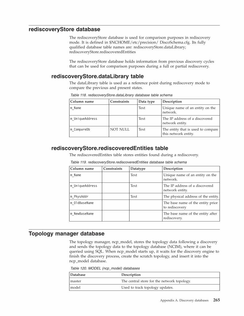
rediscoveryStore databaseThe rediscoveryStore database is used for comparison purposes in rediscoverymode. It is defined in $NCHOME/etc/precision/ DiscoSchema.cfg. Its fullyqualified database table names are: rediscoveryStore.dataLibrary;rediscoveryStore.rediscoveredEntities
The rediscoveryStore database holds information from previous discovery cyclesthat can be used for comparison purposes during a full or partial rediscovery.
rediscoveryStore.dataLibrary tableThe dataLibrary table is used as a reference point during rediscovery mode tocompare the previous and present states.
Table 118. rediscoveryStore.dataLibrary database table schema
Column name Constraints Data type Description
m_Name Text Unique name of an entity on thenetwork.
m_UniqueAddress Text The IP address of a discoverednetwork entity.
m_CompareDb NOT NULL Text The entity that is used to comparethis network entity.
rediscoveryStore.rediscoveredEntities tableThe rediscoveredEntites table stores entities found during a rediscovery.
Table 119. rediscoveryStore.rediscoveredEntities database table schema
Column name Constraints Datatype Description
m_Name Text Unique name of an entity on thenetwork.
m_UniqueAddress Text The IP address of a discoverednetwork entity.
m_PhysAddr Text The physical address of the entity.
m_OldBaseName The base name of the entity priorto rediscovery
m_NewBaseName The base name of the entity afterrediscovery.
Topology manager databaseThe topology manager, ncp_model, stores the topology data following a discoveryand sends the topology data to the topology database (NCIM), where it can bequeried using SQL. When ncp_model starts up, it waits for the discovery engine tofinish the discovery process, create the scratch topology, and insert it into thencp_model database.
Table 120. MODEL (ncp_model) databases
Database Description
master The central store for the network topology.
model Used to track topology updates.
Appendix A. Discovery databases 265
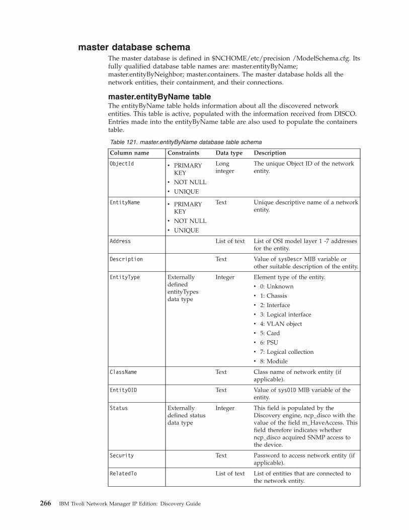
master database schemaThe master database is defined in $NCHOME/etc/precision /ModelSchema.cfg. Itsfully qualified database table names are: master.entityByName;master.entityByNeighbor; master.containers. The master database holds all thenetwork entities, their containment, and their connections.
master.entityByName tableThe entityByName table holds information about all the discovered networkentities. This table is active, populated with the information received from DISCO.Entries made into the entityByName table are also used to populate the containerstable.
Table 121. master.entityByName database table schema
Column name Constraints Data type Description
ObjectId v PRIMARYKEY
v NOT NULL
v UNIQUE
Longinteger
The unique Object ID of the networkentity.
EntityName v PRIMARYKEY
v NOT NULL
v UNIQUE
Text Unique descriptive name of a networkentity.
Address List of text List of OSI model layer 1 -7 addressesfor the entity.
Description Text Value of sysDescr MIB variable orother suitable description of the entity.
EntityType ExternallydefinedentityTypesdata type
Integer Element type of the entity.
v 0: Unknown
v 1: Chassis
v 2: Interface
v 3: Logical interface
v 4: VLAN object
v 5: Card
v 6: PSU
v 7: Logical collection
v 8: Module
ClassName Text Class name of network entity (ifapplicable).
EntityOID Text Value of sysOID MIB variable of theentity.
Status Externallydefined statusdata type
Integer This field is populated by theDiscovery engine, ncp_disco with thevalue of the field m_HaveAccess. Thisfield therefore indicates whetherncp_disco acquired SNMP access tothe device.
Security Text Password to access network entity (ifapplicable).
RelatedTo List of text List of entities that are connected tothe network entity.
266 IBM Tivoli Network Manager IP Edition: Discovery Guide
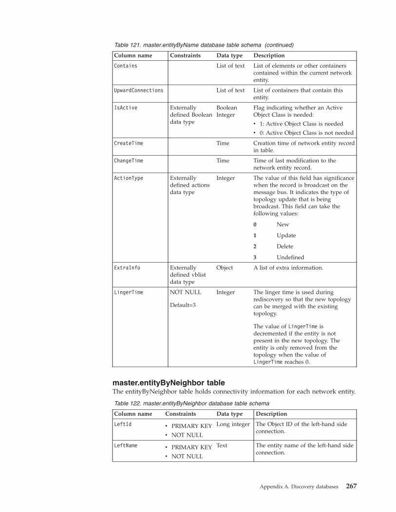
Table 121. master.entityByName database table schema (continued)
Column name Constraints Data type Description
Contains List of text List of elements or other containerscontained within the current networkentity.
UpwardConnections List of text List of containers that contain thisentity.
IsActive Externallydefined Booleandata type
BooleanInteger
Flag indicating whether an ActiveObject Class is needed:
v 1: Active Object Class is needed
v 0: Active Object Class is not needed
CreateTime Time Creation time of network entity recordin table.
ChangeTime Time Time of last modification to thenetwork entity record.
ActionType Externallydefined actionsdata type
Integer The value of this field has significancewhen the record is broadcast on themessage bus. It indicates the type oftopology update that is beingbroadcast. This field can take thefollowing values:
0 New
1 Update
2 Delete
3 Undefined
ExtraInfo Externallydefined vblistdata type
Object A list of extra information.
LingerTime NOT NULL
Default=3
Integer The linger time is used duringrediscovery so that the new topologycan be merged with the existingtopology.
The value of LingerTime isdecremented if the entity is notpresent in the new topology. Theentity is only removed from thetopology when the value ofLingerTime reaches 0.
master.entityByNeighbor tableThe entityByNeighbor table holds connectivity information for each network entity.
Table 122. master.entityByNeighbor database table schema
Column name Constraints Data type Description
LeftId v PRIMARY KEY
v NOT NULL
Long integer The Object ID of the left-hand sideconnection.
LeftName v PRIMARY KEY
v NOT NULL
Text The entity name of the left-hand sideconnection.
Appendix A. Discovery databases 267
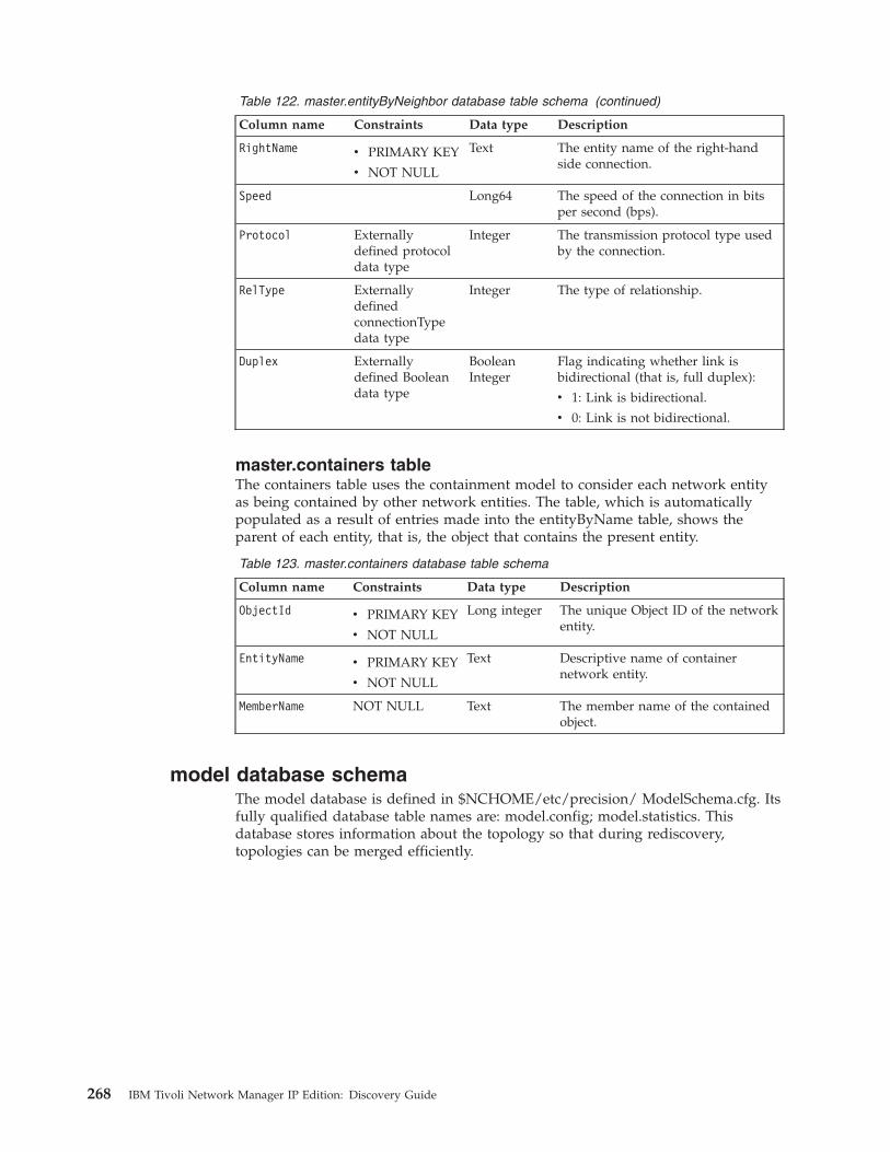
Table 122. master.entityByNeighbor database table schema (continued)
Column name Constraints Data type Description
RightName v PRIMARY KEY
v NOT NULL
Text The entity name of the right-handside connection.
Speed Long64 The speed of the connection in bitsper second (bps).
Protocol Externallydefined protocoldata type
Integer The transmission protocol type usedby the connection.
RelType ExternallydefinedconnectionTypedata type
Integer The type of relationship.
Duplex Externallydefined Booleandata type
BooleanInteger
Flag indicating whether link isbidirectional (that is, full duplex):
v 1: Link is bidirectional.
v 0: Link is not bidirectional.
master.containers tableThe containers table uses the containment model to consider each network entityas being contained by other network entities. The table, which is automaticallypopulated as a result of entries made into the entityByName table, shows theparent of each entity, that is, the object that contains the present entity.
Table 123. master.containers database table schema
Column name Constraints Data type Description
ObjectId v PRIMARY KEY
v NOT NULL
Long integer The unique Object ID of the networkentity.
EntityName v PRIMARY KEY
v NOT NULL
Text Descriptive name of containernetwork entity.
MemberName NOT NULL Text The member name of the containedobject.
model database schemaThe model database is defined in $NCHOME/etc/precision/ ModelSchema.cfg. Itsfully qualified database table names are: model.config; model.statistics. Thisdatabase stores information about the topology so that during rediscovery,topologies can be merged efficiently.
268 IBM Tivoli Network Manager IP Edition: Discovery Guide
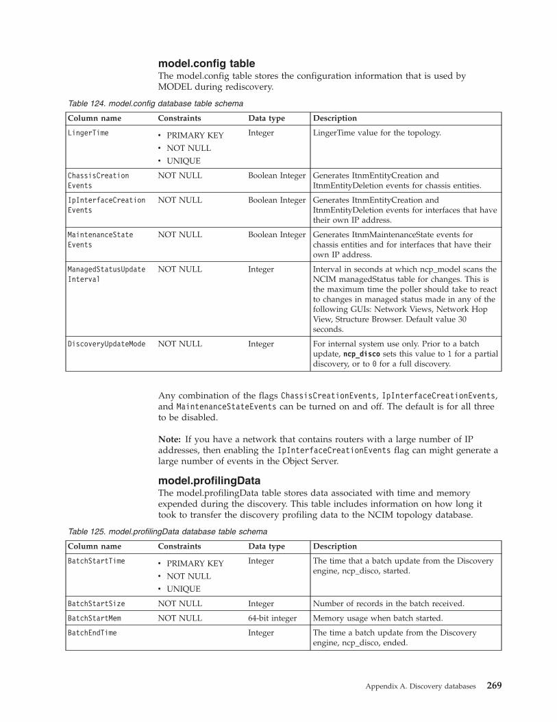
model.config tableThe model.config table stores the configuration information that is used byMODEL during rediscovery.
Table 124. model.config database table schema
Column name Constraints Data type Description
LingerTime v PRIMARY KEY
v NOT NULL
v UNIQUE
Integer LingerTime value for the topology.
ChassisCreationEvents
NOT NULL Boolean Integer Generates ItnmEntityCreation andItnmEntityDeletion events for chassis entities.
IpInterfaceCreationEvents
NOT NULL Boolean Integer Generates ItnmEntityCreation andItnmEntityDeletion events for interfaces that havetheir own IP address.
MaintenanceStateEvents
NOT NULL Boolean Integer Generates ItnmMaintenanceState events forchassis entities and for interfaces that have theirown IP address.
ManagedStatusUpdateInterval
NOT NULL Integer Interval in seconds at which ncp_model scans theNCIM managedStatus table for changes. This isthe maximum time the poller should take to reactto changes in managed status made in any of thefollowing GUIs: Network Views, Network HopView, Structure Browser. Default value 30seconds.
DiscoveryUpdateMode NOT NULL Integer For internal system use only. Prior to a batchupdate, ncp_disco sets this value to 1 for a partialdiscovery, or to 0 for a full discovery.
Any combination of the flags ChassisCreationEvents, IpInterfaceCreationEvents,and MaintenanceStateEvents can be turned on and off. The default is for all threeto be disabled.
Note: If you have a network that contains routers with a large number of IPaddresses, then enabling the IpInterfaceCreationEvents flag can might generate alarge number of events in the Object Server.
model.profilingDataThe model.profilingData table stores data associated with time and memoryexpended during the discovery. This table includes information on how long ittook to transfer the discovery profiling data to the NCIM topology database.
Table 125. model.profilingData database table schema
Column name Constraints Data type Description
BatchStartTime v PRIMARY KEY
v NOT NULL
v UNIQUE
Integer The time that a batch update from the Discoveryengine, ncp_disco, started.
BatchStartSize NOT NULL Integer Number of records in the batch received.
BatchStartMem NOT NULL 64-bit integer Memory usage when batch started.
BatchEndTime Integer The time a batch update from the Discoveryengine, ncp_disco, ended.
Appendix A. Discovery databases 269
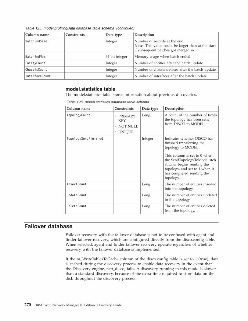
Table 125. model.profilingData database table schema (continued)
Column name Constraints Data type Description
BatchEndSize Integer Number of records at the end.Note: This value could be larger than at the startif subsequent batches got merged in.
BatchEndMem 64-bit integer Memory usage when batch ended.
EntityCount Integer Number of entities after the batch update.
ChassisCount Integer Number of chassis devices after the batch update.
InterfaceCount Integer Number of interfaces after the batch update.
model.statistics tableThe model.statistics table stores information about previous discoveries.
Table 126. model.statistics database table schema
Column name Constraints Data type Description
TopologyCount v PRIMARYKEY
v NOT NULL
v UNIQUE
Long A count of the number of timesthe topology has been sentfrom DISCO to MODEL.
TopologySendFinished Integer Indicates whether DISCO hasfinished transferring thetopology to MODEL.
This column is set to 0 whenthe SendTopologyToModel.stchstitcher begins sending thetopology, and set to 1 when ithas completed sending thetopology.
InsertCount Long The number of entities insertedinto the topology.
UpdateCount Long The number of entities updatedin the topology.
DeleteCount Long The number of entities deletedfrom the topology.
Failover databaseFailover recovery with the failover database is not to be confused with agent andfinder failover recovery, which are configured directly from the disco.config table.When selected, agent and finder failover recovery operate regardless of whetherrecovery with the failover database is implemented.
If the m_WriteTablesToCache column of the disco.config table is set to 1 (true), datais cached during the discovery process to enable data recovery in the event thatthe Discovery engine, ncp_disco, fails. A discovery running in this mode is slowerthan a standard discovery, because of the extra time required to store data on thedisk throughout the discovery process.
270 IBM Tivoli Network Manager IP Edition: Discovery Guide
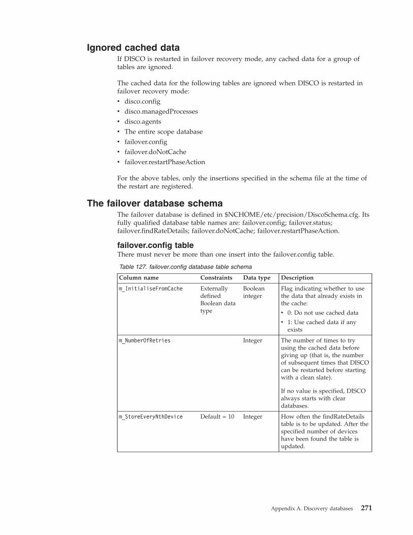
Ignored cached dataIf DISCO is restarted in failover recovery mode, any cached data for a group oftables are ignored.
The cached data for the following tables are ignored when DISCO is restarted infailover recovery mode:v disco.configv disco.managedProcessesv disco.agentsv The entire scope databasev failover.configv failover.doNotCachev failover.restartPhaseAction
For the above tables, only the insertions specified in the schema file at the time ofthe restart are registered.
The failover database schemaThe failover database is defined in $NCHOME/etc/precision/DiscoSchema.cfg. Itsfully qualified database table names are: failover.config; failover.status;failover.findRateDetails; failover.doNotCache; failover.restartPhaseAction.
failover.config tableThere must never be more than one insert into the failover.config table.
Table 127. failover.config database table schema
Column name Constraints Data type Description
m_InitialiseFromCache ExternallydefinedBoolean datatype
Booleaninteger
Flag indicating whether to usethe data that already exists inthe cache:
v 0: Do not use cached data
v 1: Use cached data if anyexists
m_NumberOfRetries Integer The number of times to tryusing the cached data beforegiving up (that is, the numberof subsequent times that DISCOcan be restarted before startingwith a clean slate).
If no value is specified, DISCOalways starts with cleardatabases.
m_StoreEveryNthDevice Default = 10 Integer How often the findRateDetailstable is to be updated. After thespecified number of deviceshave been found the table isupdated.
Appendix A. Discovery databases 271
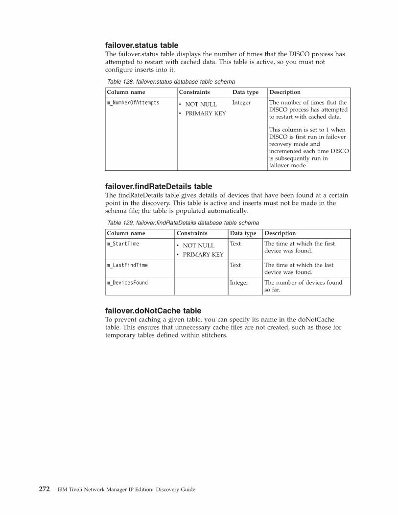
failover.status tableThe failover.status table displays the number of times that the DISCO process hasattempted to restart with cached data. This table is active, so you must notconfigure inserts into it.
Table 128. failover.status database table schema
Column name Constraints Data type Description
m_NumberOfAttempts v NOT NULL
v PRIMARY KEY
Integer The number of times that theDISCO process has attemptedto restart with cached data.
This column is set to 1 whenDISCO is first run in failoverrecovery mode andincremented each time DISCOis subsequently run infailover mode.
failover.findRateDetails tableThe findRateDetails table gives details of devices that have been found at a certainpoint in the discovery. This table is active and inserts must not be made in theschema file; the table is populated automatically.
Table 129. failover.findRateDetails database table schema
Column name Constraints Data type Description
m_StartTime v NOT NULL
v PRIMARY KEY
Text The time at which the firstdevice was found.
m_LastFindTime Text The time at which the lastdevice was found.
m_DevicesFound Integer The number of devices foundso far.
failover.doNotCache tableTo prevent caching a given table, you can specify its name in the doNotCachetable. This ensures that unnecessary cache files are not created, such as those fortemporary tables defined within stitchers.
272 IBM Tivoli Network Manager IP Edition: Discovery Guide
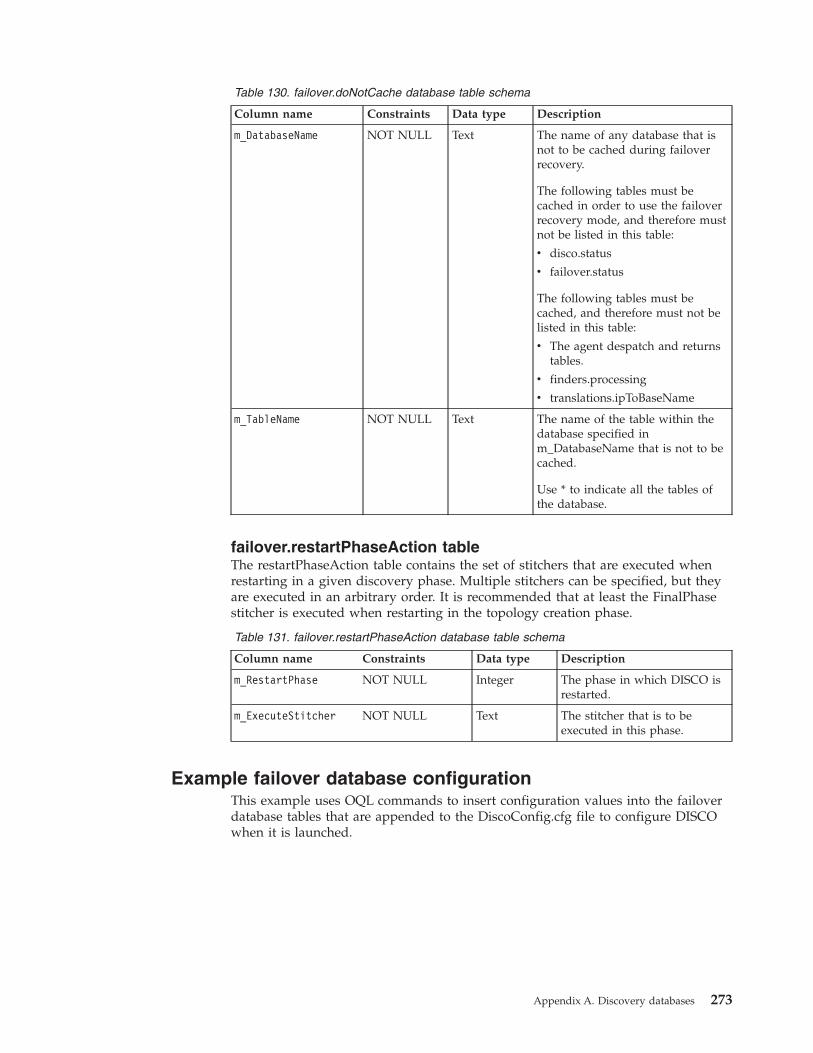
Table 130. failover.doNotCache database table schema
Column name Constraints Data type Description
m_DatabaseName NOT NULL Text The name of any database that isnot to be cached during failoverrecovery.
The following tables must becached in order to use the failoverrecovery mode, and therefore mustnot be listed in this table:
v disco.status
v failover.status
The following tables must becached, and therefore must not belisted in this table:
v The agent despatch and returnstables.
v finders.processing
v translations.ipToBaseName
m_TableName NOT NULL Text The name of the table within thedatabase specified inm_DatabaseName that is not to becached.
Use * to indicate all the tables ofthe database.
failover.restartPhaseAction tableThe restartPhaseAction table contains the set of stitchers that are executed whenrestarting in a given discovery phase. Multiple stitchers can be specified, but theyare executed in an arbitrary order. It is recommended that at least the FinalPhasestitcher is executed when restarting in the topology creation phase.
Table 131. failover.restartPhaseAction database table schema
Column name Constraints Data type Description
m_RestartPhase NOT NULL Integer The phase in which DISCO isrestarted.
m_ExecuteStitcher NOT NULL Text The stitcher that is to beexecuted in this phase.
Example failover database configurationThis example uses OQL commands to insert configuration values into the failoverdatabase tables that are appended to the DiscoConfig.cfg file to configure DISCOwhen it is launched.
Appendix A. Discovery databases 273
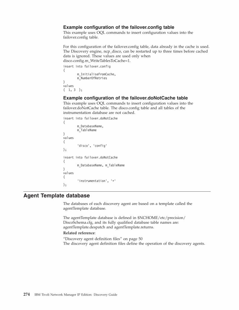
Example configuration of the failover.config tableThis example uses OQL commands to insert configuration values into thefailover.config table.
For this configuration of the failover.config table, data already in the cache is used.The Discovery engine, ncp_disco, can be restarted up to three times before cacheddata is ignored. These values are used only whendisco.config.m_WriteTablesToCache=1.insert into failover.config(
m_InitialiseFromCache,m_NumberOfRetries
)values( 1, 3 );
Example configuration of the failover.doNotCache tableThis example uses OQL commands to insert configuration values into thefailover.doNotCache table. The disco.config table and all tables of theinstrumentation database are not cached.insert into failover.doNotCache(
m_DatabaseName,m_TableName
)values(
’disco’, ’config’);
insert into failover.doNotCache(
m_DatabaseName, m_TableName)values(
’instrumentation’, ’*’);
Agent Template databaseThe databases of each discovery agent are based on a template called theagentTemplate database.
The agentTemplate database is defined in $NCHOME/etc/precision/DiscoSchema.cfg, and its fully qualified database table names are:agentTemplate.despatch and agentTemplate.returns.Related reference:“Discovery agent definition files” on page 50The discovery agent definition files define the operation of the discovery agents.
274 IBM Tivoli Network Manager IP Edition: Discovery Guide
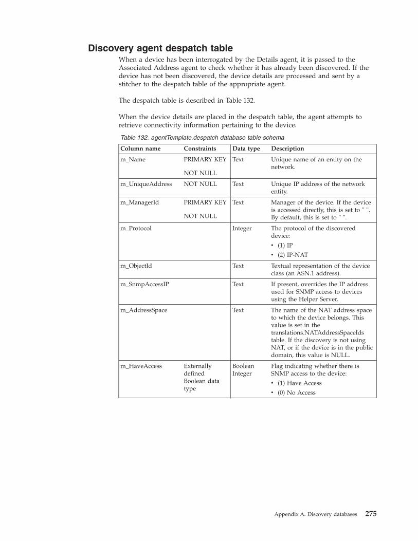
Discovery agent despatch tableWhen a device has been interrogated by the Details agent, it is passed to theAssociated Address agent to check whether it has already been discovered. If thedevice has not been discovered, the device details are processed and sent by astitcher to the despatch table of the appropriate agent.
The despatch table is described in Table 132.
When the device details are placed in the despatch table, the agent attempts toretrieve connectivity information pertaining to the device.
Table 132. agentTemplate.despatch database table schema
Column name Constraints Data type Description
m_Name PRIMARY KEY
NOT NULL
Text Unique name of an entity on thenetwork.
m_UniqueAddress NOT NULL Text Unique IP address of the networkentity.
m_ManagerId PRIMARY KEY
NOT NULL
Text Manager of the device. If the deviceis accessed directly, this is set to " ".By default, this is set to " ".
m_Protocol Integer The protocol of the discovereddevice:
v (1) IP
v (2) IP-NAT
m_ObjectId Text Textual representation of the deviceclass (an ASN.1 address).
m_SnmpAccessIP Text If present, overrides the IP addressused for SNMP access to devicesusing the Helper Server.
m_AddressSpace Text The name of the NAT address spaceto which the device belongs. Thisvalue is set in thetranslations.NATAddressSpaceIdstable. If the discovery is not usingNAT, or if the device is in the publicdomain, this value is NULL.
m_HaveAccess ExternallydefinedBoolean datatype
BooleanInteger
Flag indicating whether there isSNMP access to the device:
v (1) Have Access
v (0) No Access
Appendix A. Discovery databases 275
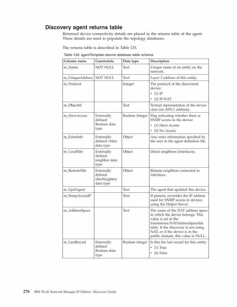
Discovery agent returns tableReturned device connectivity details are placed in the returns table of the agent.These details are used to populate the topology databases.
The returns table is described in Table 133.
Table 133. agentTemplate.returns database table schema
Column name Constraints Data type Description
m_Name NOT NULL Text Unique name of an entity on thenetwork.
m_UniqueAddress NOT NULL Text Layer 3 address of this entity.
m_Protocol Integer The protocol of the discovereddevice:
v (1) IP
v (2) IP-NAT
m_ObjectId Text Textual representation of the deviceclass (an ASN.1 address).
m_HaveAccess ExternallydefinedBoolean datatype
Boolean Integer Flag indicating whether there isSNMP access to the device:
v (1) Have Access
v (0) No Access
m_ExtraInfo Externallydefined vblistdata type
Object Any extra information specified bythe user in the agent definition file.
m_LocalNbr Externallydefinedneighbor datatype
Object Direct neighbors (interfaces).
m_RemoteNbr ExternallydefinednbrsNeighbordata type
Object Remote neighbors connected tointerfaces.
m_UpdAgent Text The agent that updated this device.
m_SnmpAccessIP Text If present, overrides the IP addressused for SNMP access to devicesusing the Helper Server.
m_AddressSpace Text The name of the NAT address spaceto which the device belongs. Thisvalue is set in thetranslations.NATAddressSpaceIdstable. If the discovery is not usingNAT, or if the device is in thepublic domain, this value is NULL.
m_LastRecord ExternallydefinedBoolean datatype
Boolean integer Is this the last record for this entity:
v (1) True
v (0) False
276 IBM Tivoli Network Manager IP Edition: Discovery Guide
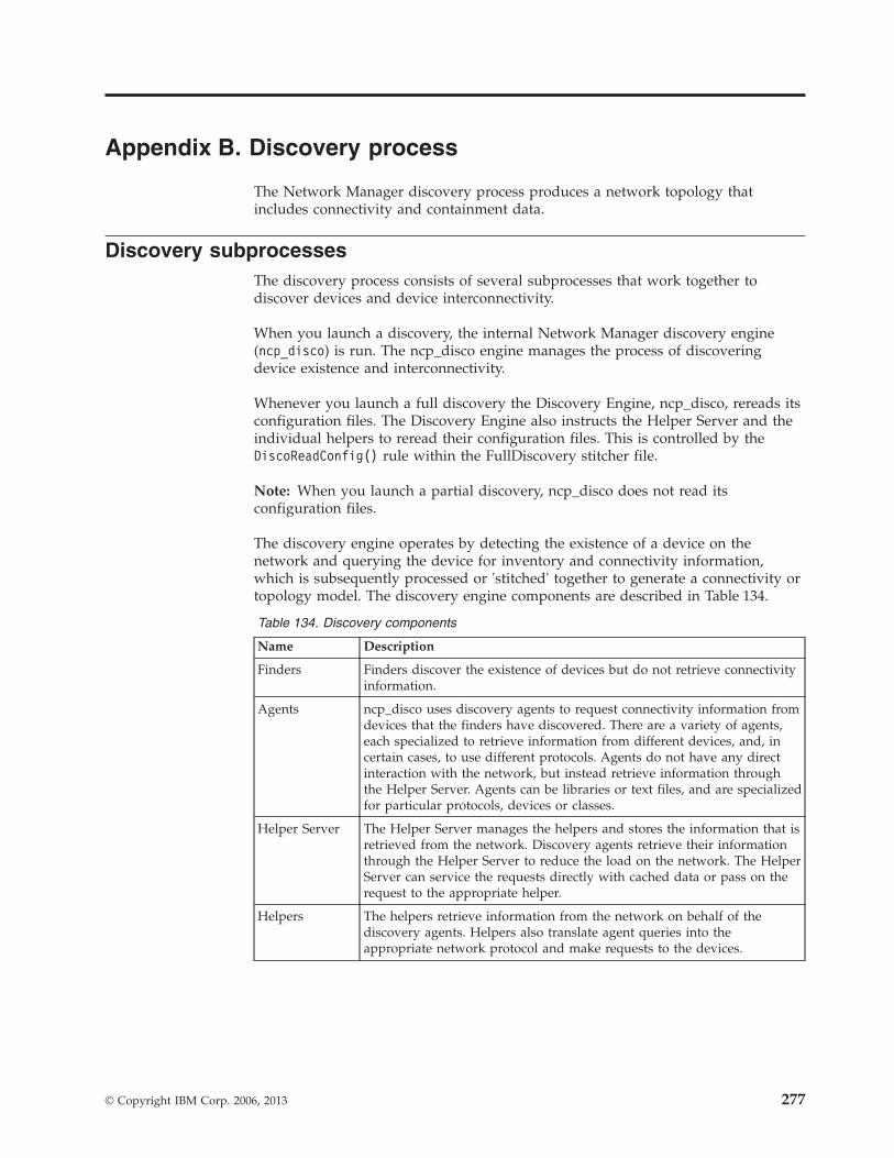
Appendix B. Discovery process
The Network Manager discovery process produces a network topology thatincludes connectivity and containment data.
Discovery subprocessesThe discovery process consists of several subprocesses that work together todiscover devices and device interconnectivity.
When you launch a discovery, the internal Network Manager discovery engine(ncp_disco) is run. The ncp_disco engine manages the process of discoveringdevice existence and interconnectivity.
Whenever you launch a full discovery the Discovery Engine, ncp_disco, rereads itsconfiguration files. The Discovery Engine also instructs the Helper Server and theindividual helpers to reread their configuration files. This is controlled by theDiscoReadConfig() rule within the FullDiscovery stitcher file.
Note: When you launch a partial discovery, ncp_disco does not read itsconfiguration files.
The discovery engine operates by detecting the existence of a device on thenetwork and querying the device for inventory and connectivity information,which is subsequently processed or 'stitched' together to generate a connectivity ortopology model. The discovery engine components are described in Table 134.
Table 134. Discovery components
Name Description
Finders Finders discover the existence of devices but do not retrieve connectivityinformation.
Agents ncp_disco uses discovery agents to request connectivity information fromdevices that the finders have discovered. There are a variety of agents,each specialized to retrieve information from different devices, and, incertain cases, to use different protocols. Agents do not have any directinteraction with the network, but instead retrieve information throughthe Helper Server. Agents can be libraries or text files, and are specializedfor particular protocols, devices or classes.
Helper Server The Helper Server manages the helpers and stores the information that isretrieved from the network. Discovery agents retrieve their informationthrough the Helper Server to reduce the load on the network. The HelperServer can service the requests directly with cached data or pass on therequest to the appropriate helper.
Helpers The helpers retrieve information from the network on behalf of thediscovery agents. Helpers also translate agent queries into theappropriate network protocol and make requests to the devices.
© Copyright IBM Corp. 2006, 2013 277
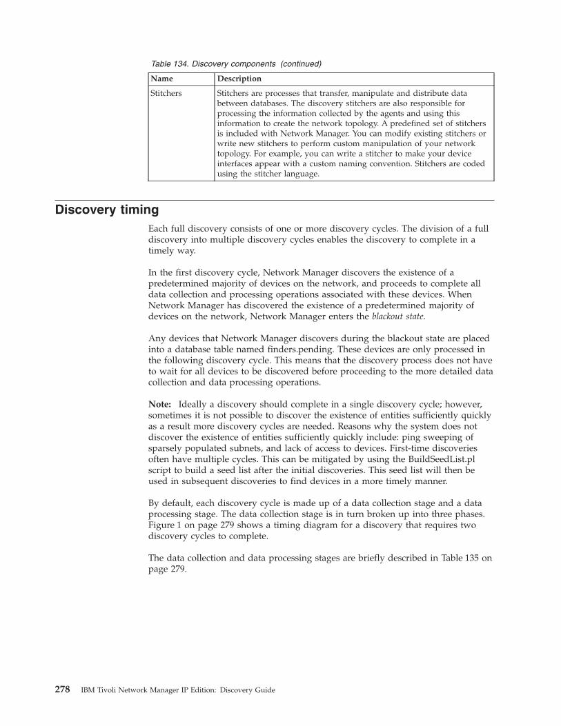
Table 134. Discovery components (continued)
Name Description
Stitchers Stitchers are processes that transfer, manipulate and distribute databetween databases. The discovery stitchers are also responsible forprocessing the information collected by the agents and using thisinformation to create the network topology. A predefined set of stitchersis included with Network Manager. You can modify existing stitchers orwrite new stitchers to perform custom manipulation of your networktopology. For example, you can write a stitcher to make your deviceinterfaces appear with a custom naming convention. Stitchers are codedusing the stitcher language.
Discovery timingEach full discovery consists of one or more discovery cycles. The division of a fulldiscovery into multiple discovery cycles enables the discovery to complete in atimely way.
In the first discovery cycle, Network Manager discovers the existence of apredetermined majority of devices on the network, and proceeds to complete alldata collection and processing operations associated with these devices. WhenNetwork Manager has discovered the existence of a predetermined majority ofdevices on the network, Network Manager enters the blackout state.
Any devices that Network Manager discovers during the blackout state are placedinto a database table named finders.pending. These devices are only processed inthe following discovery cycle. This means that the discovery process does not haveto wait for all devices to be discovered before proceeding to the more detailed datacollection and data processing operations.
Note: Ideally a discovery should complete in a single discovery cycle; however,sometimes it is not possible to discover the existence of entities sufficiently quicklyas a result more discovery cycles are needed. Reasons why the system does notdiscover the existence of entities sufficiently quickly include: ping sweeping ofsparsely populated subnets, and lack of access to devices. First-time discoveriesoften have multiple cycles. This can be mitigated by using the BuildSeedList.plscript to build a seed list after the initial discoveries. This seed list will then beused in subsequent discoveries to find devices in a more timely manner.
By default, each discovery cycle is made up of a data collection stage and a dataprocessing stage. The data collection stage is in turn broken up into three phases.Figure 1 on page 279 shows a timing diagram for a discovery that requires twodiscovery cycles to complete.
The data collection and data processing stages are briefly described in Table 135 onpage 279.
278 IBM Tivoli Network Manager IP Edition: Discovery Guide
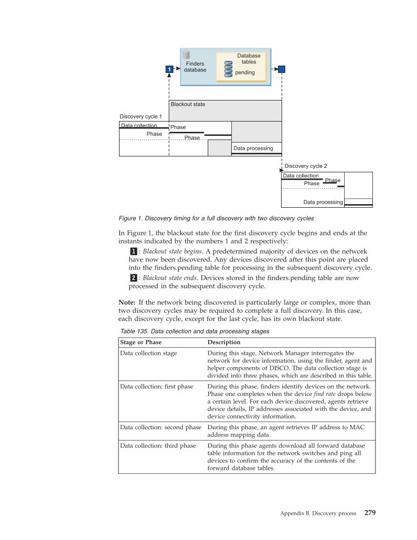
In Figure 1, the blackout state for the first discovery cycle begins and ends at theinstants indicated by the numbers 1 and 2 respectively:
�1�: Blackout state begins. A predetermined majority of devices on the networkhave now been discovered. Any devices discovered after this point are placedinto the finders.pending table for processing in the subsequent discovery cycle.�2�: Blackout state ends. Devices stored in the finders.pending table are nowprocessed in the subsequent discovery cycle.
Note: If the network being discovered is particularly large or complex, more thantwo discovery cycles may be required to complete a full discovery. In this case,each discovery cycle, except for the last cycle, has its own blackout state.
Table 135. Data collection and data processing stages
Stage or Phase Description
Data collection stage During this stage, Network Manager interrogates thenetwork for device information, using the finder, agent andhelper components of DISCO. The data collection stage isdivided into three phases, which are described in this table.
Data collection: first phase During this phase, finders identify devices on the network.Phase one completes when the device find rate drops belowa certain level. For each device discovered, agents retrievedevice details, IP addresses associated with the device, anddevice connectivity information.
Data collection: second phase During this phase, an agent retrieves IP address to MACaddress mapping data.
Data collection: third phase During this phase agents download all forward databasetable information for the network switches and ping alldevices to confirm the accuracy of the contents of theforward database tables.
1
Blackout state
Discovery cycle 1
Data collection
Discovery cycle 2
Data processing
Data processing
Data collection
Phase
Phase
Phase
Phase
Phase
pending
Findersdatabase
Databasetables
Figure 1. Discovery timing for a full discovery with two discovery cycles
Appendix B. Discovery process 279
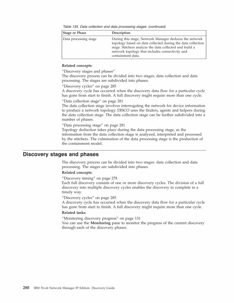
Table 135. Data collection and data processing stages (continued)
Stage or Phase Description
Data processing stage During this stage, Network Manager deduces the networktopology based on data collected during the data collectionstage. Stitchers analyze the data collected and build anetwork topology that includes connectivity andcontainment data.
Related concepts:“Discovery stages and phases”The discovery process can be divided into two stages: data collection and dataprocessing. The stages are subdivided into phases.“Discovery cycles” on page 285A discovery cycle has occurred when the discovery data flow for a particular cyclehas gone from start to finish. A full discovery might require more than one cycle.“Data collection stage” on page 281The data collection stage involves interrogating the network for device informationto produce a network topology. DISCO uses the finders, agents and helpers duringthe data collection stage. The data collection stage can be further subdivided into anumber of phases.“Data processing stage” on page 281Topology deduction takes place during the data processing stage, as theinformation from the data collection stage is analyzed, interpreted and processedby the stitchers. The culmination of the data processing stage is the production ofthe containment model.
Discovery stages and phasesThe discovery process can be divided into two stages: data collection and dataprocessing. The stages are subdivided into phases.Related concepts:“Discovery timing” on page 278Each full discovery consists of one or more discovery cycles. The division of a fulldiscovery into multiple discovery cycles enables the discovery to complete in atimely way.“Discovery cycles” on page 285A discovery cycle has occurred when the discovery data flow for a particular cyclehas gone from start to finish. A full discovery might require more than one cycle.Related tasks:“Monitoring discovery progress” on page 131You can use the Monitoring pane to monitor the progress of the current discoverythrough each of the discovery phases.
280 IBM Tivoli Network Manager IP Edition: Discovery Guide
Data processing stageTopology deduction takes place during the data processing stage, as theinformation from the data collection stage is analyzed, interpreted and processedby the stitchers. The culmination of the data processing stage is the production ofthe containment model.
The data processing stage corresponds to creating the topology. This is the finalconceptual step in the discovery cycle.
The data processing and data collection stages usually overlap, because you canconfigure the stitchers to begin processing connectivity information from differentdiscovery agents before the main stitching operation begins.Related concepts:“Discovery timing” on page 278Each full discovery consists of one or more discovery cycles. The division of a fulldiscovery into multiple discovery cycles enables the discovery to complete in atimely way.“Creating the topology” on page 292The creation of the topology is carried out in several steps.
Data collection stageThe data collection stage involves interrogating the network for device informationto produce a network topology. DISCO uses the finders, agents and helpers duringthe data collection stage. The data collection stage can be further subdivided into anumber of phases.
First phase
In the first phase of data collection, the finders identify all the devices that exist onthe network. Generally, a phase can be completed when all the launched processeshave completed their operation. However, although you might want to wait untilall devices have been discovered by the finders before proceeding to phase two, itis inefficient to hold back the discovery process by waiting indefinitely. The firstphase therefore completes when the find rate drops below a certain level,determined by no devices being discovered for the amount of time specified indisco.config.m_NothingFndPeriod.
The following conceptual steps in the discovery cycle take place during datacollection phase one:v Discovering device existencev Discovering device details (standard)v Discovering associated device addressesv Discovering device connectivity
Agents in the first phase
Some agents return data that can be used to find other devices, for example, the IPaddress of remote neighbors, or the subnet within which a local neighbor exists.This mechanism is known as feedback.
The Feedback stitcher manages feedback by sending the information returned bythe agents to the Ping finder for inclusion in the discovery. However, the blackout
Appendix B. Discovery process 281
state ensures that any agent involved in the feedback process must be run in phaseone for devices to be discovered in the current discovery cycle.
Phase one also usually involves the Switch discovery agents downloading allVLAN and interface information.
Blackout state
After phase one, the discovery enters the blackout state. The finders have discoveredthe existence of a pre-determined majority of devices on the network. Any newdevice addresses discovered in the blackout state, either by the finders orrecursively by a discovery agent, are put into the finders.pending database table.
Devices in the finders.pending database table are processed in the next discovery.If there are devices in the finders.pending database table, the next discovery startsas soon as the current discovery finishes.
Second phase
After the criteria for the completion of phase one have been fulfilled, phase twobegins. To map layers two and three of the OSI model, the ARP Cache discoveryagent populates the Helper Server with ARP data, which is a list of device IPaddress-to-MAC address resolution.
Before the discovery can transfer from phase two to phase three, the processesfrom phase two must have completed their operation. An agent is considered tohave finished after all entities in its despatch table are also in its returns table.
The agents are multithread, and records of discovered devices passed to the agentsare tagged with a certain phase. Consequently, at any time an agent can beprocessing devices in two separate phases. If any action that should have occurredin phase two is detected after phase three has begun, phase three continues whilethe agent runs through phase two processing.
Third phase
By phase three, the discovery process has full knowledge of the devices that existwithin the network (acquired from phase one) and access to full IPaddress-to-MAC address mappings for all devices in the Helper Server (acquiredfrom phase two). The Switch agents can now proceed to download all the forwarddatabase table information of the network switches whilst pinging all devices toconfirm the accuracy of the contents of the forward database tables.
When phase three has finished, which is signified by the completion of allprocesses scheduled to run in the phase, the discovery is ready to proceed from thedata collection stage to the data processing stage, where all the connectivityinformation is knitted together to form a network topology.
Impact of the stages and phases approach on DISCO processes
The division of the data collection stage into phases affects all the processesinvolved in the discovery and network topology deduction, because the phases areprocessed in order. Any given phase cannot begin until the criteria for completionof the previous phase have been met.
282 IBM Tivoli Network Manager IP Edition: Discovery Guide
All the processes of DISCO must therefore have an associated phase (or phases) inwhich they are allowed to operate. Thus, whilst the finders are typically configuredto run through all phases, you might want to configure certain discovery agents tooperate only within a specific phase(s). The flexibility of DISCO allows you to haveprocesses that are intelligent enough to behave differently when they operatewithin different phases, and can pass control to other processes or stop operationuntil the start of their next operational phase.Related concepts:“Discovery timing” on page 278Each full discovery consists of one or more discovery cycles. The division of a fulldiscovery into multiple discovery cycles enables the discovery to complete in atimely way.“Discovering device existence” on page 286The discovery of device existence is carried out in several steps.“Discovering device details (standard)” on page 287The standard discovery of device details is carried out in several steps.“Discovering associated device addresses” on page 289There are several steps in the process flow during the discovery of associateddevice addresses.“Discovering device connectivity” on page 291The discovery of device connectivity is carried out in several steps.
Advantages of staged discoveryThere are several reasons why it is advantageous to apply a staged and phasedapproach to discovery.
Switch connectivity
In determining the connectivity of some devices, it is sometimes necessary for thediscovery agent to know all the devices that exist before requesting particularManagement Information Base (MIB) variable(s), especially if the requestedinformation is transient.
An example is when the layer 2 agents discover connectivity between Ethernetswitches. Ethernet switches have forward database tables that expire over time. So,to ensure that a switch has a fully populated forward database table at the time ofinterrogation, you could ping all devices associated with the switch.
You would therefore configure the switch discovery agents to perform some otherprocessing in data collection phase one. After the agents receive the signal thatphase one has been completed (that is, all devices have been found) they can startphase two operations. For example, they could ping all devices within thediscovery domain while downloading the forward database tables for all switches.
Mapping subnet boundaries
One limitation of configuring individual discovery agents to make individual ARPrequests directly from the Helper Server is that the ARP helper cannot runsimultaneously on multiple subnets unless it is specifically configured to do so. Toresolve this problem, use a special ARP Cache discovery agent that imitates ageneric discovery agent (in the sense that entities can be sent to it) but that alsocan map boundaries or different layers of the OSI model.
Appendix B. Discovery process 283
The ARP Cache discovery agent can inquire about ARP caches that exist onrouters. It uses this information to populate the ARP helper database within theHelper Server and build up full device IP address to MAC address mappingwithout having to rely on the ARP helper.
This approach can be applied when using switch discovery agents that need toperform IP address-to-MAC address resolution before they can start operation.Following the example above, you could configure your discovery data collectionstage to have three phases:v Phase one: Find all devices that exist on the network.v Phase two: Use the ARP Cache discovery agent to populate the Helper Server
with full IP address to MAC address mappings.v Phase three: Ping all devices and invoke the switch discovery agents by
downloading the forward database tables for all switches in the network, usingthe IP address to MAC address mappings determined in phase two.
Multiphase discovery agents
Another possible consequence of dividing the data collection stage into phases isthat you can configure the discovery agents to perform different operations withindifferent phases.
Although a discovery agent is programmed to start operating in phase two, itcould also conduct some other operation in phase one. This is because the end ofphase one signifies only that all devices have been discovered. The agent could beconfigured to perform other actions such as downloading interfaces, issuing Telnetrequests, or downloading other MIB variables during phase one. Only after phasetwo has started does the agent begin to process instructions specific to phase two.
Tip: It is good practice to configure the discovery to occur over multiple phases, toensure maximum accuracy of the deduced topology.
Effect of discovery multiphasing on network trafficOne of the main benefits of multiphasing is reduced network traffic.
Because similar types of network requests are grouped in phases, data can becached in the Helper Server to reduce the network load. The Helper Server is theintermediary between the discovery agents and the network, and can amalgamatemultiple pings of the same device into one block so that they are resolved into asingle ping.
The Helper Server also has a request pool that ensures that the Helper Server doesnot overload the network. The request pool does this by restricting the number ofsimultaneously-handled requests.
Criteria for multiphasingThe main criterion for configuring a discovery that has multiple phases is to assessthe requirements of the different operations that need to be performed during thediscovery process. For example, Ethernet-based discovery agents require at leasttwo phases. It is possible to have discovery agents that can operate in any phase.
284 IBM Tivoli Network Manager IP Edition: Discovery Guide
Managing the phasesThe different phases of the discovery data collection stage are managed by aninternal phase manager.
The phase manager:v Reads the maximum overall phase number and calculates the total number of
phases when all the discovery agent and stitcher definition files are loaded.v Calculates the phase and process dependencies, that is, which discovery agents
are scheduled to run in which phases.v Monitors the processes running during the phases.
When the phase manager detects that all the processes for the current phase havecompleted, it sends a signal indicating phase completion for all the processes thatare waiting to be launched in the next phase.
Discovery cyclesA discovery cycle has occurred when the discovery data flow for a particular cyclehas gone from start to finish. A full discovery might require more than one cycle.
The discovery data flow can be categorized into the following conceptual steps:v Discovering device existencev Discovering device details (standard)v Discovering device details (context-sensitive)v Discovering associated device addressesv Discovering device connectivityv Creating the topology
These steps follow the discovery data flow in order from start to finish, with theexception of discovering device details (context-sensitive), which replacesdiscovering device details (standard) if the discovery is context-sensitive.Related concepts:“Discovery timing” on page 278Each full discovery consists of one or more discovery cycles. The division of a fulldiscovery into multiple discovery cycles enables the discovery to complete in atimely way.“Discovery stages and phases” on page 280The discovery process can be divided into two stages: data collection and dataprocessing. The stages are subdivided into phases.“Discovery process with EMS integration” on page 295Network Manager collects topology data from an EMS using collectors.
Appendix B. Discovery process 285
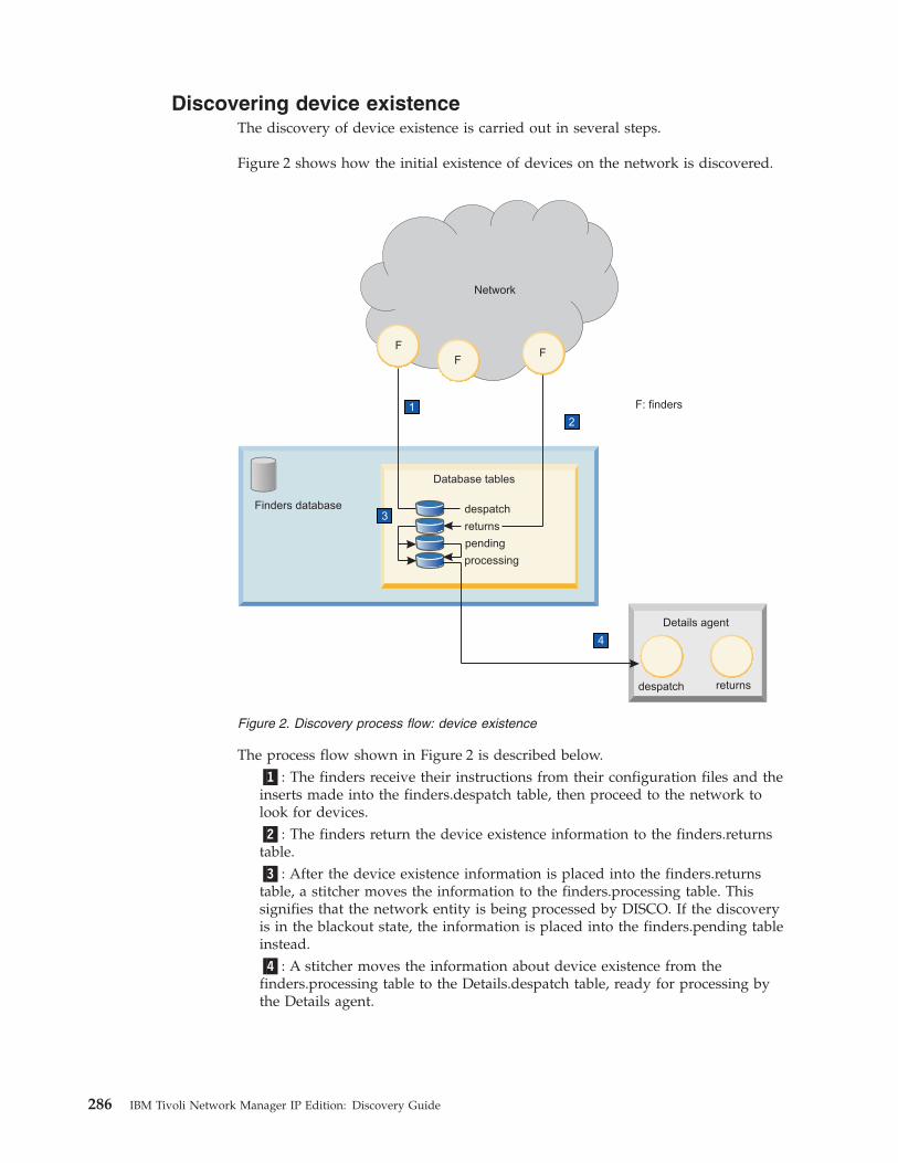
Discovering device existenceThe discovery of device existence is carried out in several steps.
Figure 2 shows how the initial existence of devices on the network is discovered.
The process flow shown in Figure 2 is described below.�1�: The finders receive their instructions from their configuration files and theinserts made into the finders.despatch table, then proceed to the network tolook for devices.�2�: The finders return the device existence information to the finders.returnstable.�3�: After the device existence information is placed into the finders.returnstable, a stitcher moves the information to the finders.processing table. Thissignifies that the network entity is being processed by DISCO. If the discoveryis in the blackout state, the information is placed into the finders.pending tableinstead.�4�: A stitcher moves the information about device existence from thefinders.processing table to the Details.despatch table, ready for processing bythe Details agent.
1
2
33
4
despatch
F
FF
F: finders
Details agent
Network
returns
Finders database
Database tables
despatch
returns
pending
processing
Figure 2. Discovery process flow: device existence
286 IBM Tivoli Network Manager IP Edition: Discovery Guide
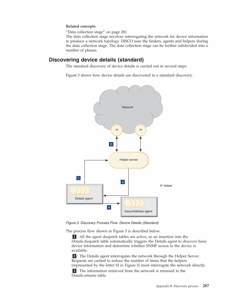
Related concepts:“Data collection stage” on page 281The data collection stage involves interrogating the network for device informationto produce a network topology. DISCO uses the finders, agents and helpers duringthe data collection stage. The data collection stage can be further subdivided into anumber of phases.
Discovering device details (standard)The standard discovery of device details is carried out in several steps.
Figure 3 shows how device details are discovered in a standard discovery.
The process flow shown in Figure 3 is described below.�1�: All the agent despatch tables are active, so an insertion into theDetails.despatch table automatically triggers the Details agent to discover basicdevice information and determine whether SNMP access to the device isavailable.�2�: The Details agent interrogates the network through the Helper Server.Requests are cached to reduce the number of times that the helpers(represented by the letter H in Figure 3) must interrogate the network directly.�3�: The information retrieved from the network is returned to theDetails.returns table.
1
2
33
4
H H
Helper server
Network
Details agent
H: helper
AssocAddress agent
Figure 3. Discovery Process Flow: Device Details (Standard)
Appendix B. Discovery process 287
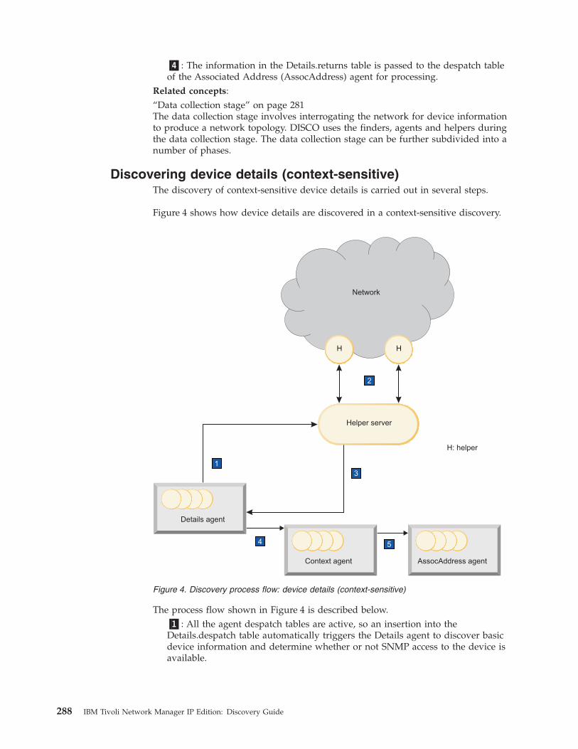
�4�: The information in the Details.returns table is passed to the despatch tableof the Associated Address (AssocAddress) agent for processing.
Related concepts:“Data collection stage” on page 281The data collection stage involves interrogating the network for device informationto produce a network topology. DISCO uses the finders, agents and helpers duringthe data collection stage. The data collection stage can be further subdivided into anumber of phases.
Discovering device details (context-sensitive)The discovery of context-sensitive device details is carried out in several steps.
Figure 4 shows how device details are discovered in a context-sensitive discovery.
The process flow shown in Figure 4 is described below.�1�: All the agent despatch tables are active, so an insertion into theDetails.despatch table automatically triggers the Details agent to discover basicdevice information and determine whether or not SNMP access to the device isavailable.
5
1
2
33
4
H H
Helper server
Network
Details agent
H: helper
AssocAddress agentContext agent
Figure 4. Discovery process flow: device details (context-sensitive)
288 IBM Tivoli Network Manager IP Edition: Discovery Guide
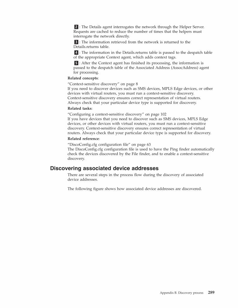
�2�: The Details agent interrogates the network through the Helper Server.Requests are cached to reduce the number of times that the helpers mustinterrogate the network directly.�3�: The information retrieved from the network is returned to theDetails.returns table.�4�: The information in the Details.returns table is passed to the despatch tableof the appropriate Context agent, which adds context tags.�5�: After the Context agent has finished its processing, the information ispassed to the despatch table of the Associated Address (AssocAddress) agentfor processing.
Related concepts:“Context-sensitive discovery” on page 8If you need to discover devices such as SMS devices, MPLS Edge devices, or otherdevices with virtual routers, you must run a context-sensitive discovery.Context-sensitive discovery ensures correct representation of virtual routers.Always check that your particular device type is supported for discovery.Related tasks:“Configuring a context-sensitive discovery” on page 102If you have devices that you need to discover such as SMS devices, MPLS Edgedevices, or other devices with virtual routers, you must run a context-sensitivediscovery. Context-sensitive discovery ensures correct representation of virtualrouters. Always check that your particular device type is supported for discovery.Related reference:“DiscoConfig.cfg configuration file” on page 63The DiscoConfig.cfg configuration file is used to have the Ping finder automaticallycheck the devices discovered by the File finder, and to enable a context-sensitivediscovery.
Discovering associated device addressesThere are several steps in the process flow during the discovery of associateddevice addresses.
The following figure shows how associated device addresses are discovered.
Appendix B. Discovery process 289
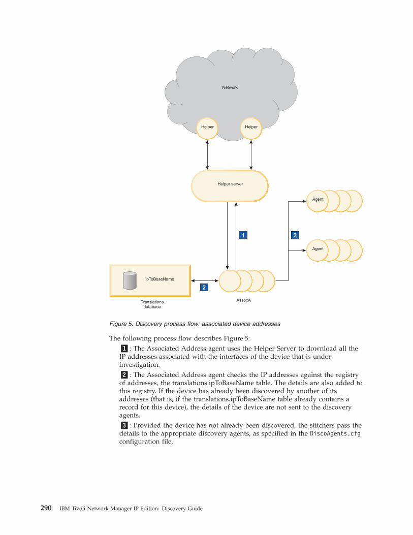
The following process flow describes Figure 5:�1�: The Associated Address agent uses the Helper Server to download all theIP addresses associated with the interfaces of the device that is underinvestigation.�2�: The Associated Address agent checks the IP addresses against the registryof addresses, the translations.ipToBaseName table. The details are also added tothis registry. If the device has already been discovered by another of itsaddresses (that is, if the translations.ipToBaseName table already contains arecord for this device), the details of the device are not sent to the discoveryagents.�3�: Provided the device has not already been discovered, the stitchers pass thedetails to the appropriate discovery agents, as specified in the DiscoAgents.cfgconfiguration file.
1
2
33
Network
Helper Helper
Helper server
ipToBaseName
Translationsdatabase
Agent
Agent
AssocA
Figure 5. Discovery process flow: associated device addresses
290 IBM Tivoli Network Manager IP Edition: Discovery Guide

Related concepts:“Data collection stage” on page 281The data collection stage involves interrogating the network for device informationto produce a network topology. DISCO uses the finders, agents and helpers duringthe data collection stage. The data collection stage can be further subdivided into anumber of phases.
Discovering device connectivityThe discovery of device connectivity is carried out in several steps.
The following figure shows how device connectivity is discovered, as well as howdevices are discovered recursively.
The following process flow describes Figure 6:�1�: When information is inserted into the despatch table of a discovery agent,the agent attempts to discover the connectivity information for that device. Theagent sets up a TCP socket-based communication link with the Helper Serverand requests the appropriate connectivity information.�2�: A stitcher passes the addresses of the remote neighbors of the device, andthe subnet address or addresses of the device, to a finder for discovery. Becausethese addresses might not exist, and also might not be in the specifieddiscovery scope, the addresses must run through the discovery process fromthe beginning.
1 1
2 2
AgentAgent Helper server
Network
HelperHelper
Findersdatabase
Figure 6. Discovery process flow: device connectivity
Appendix B. Discovery process 291
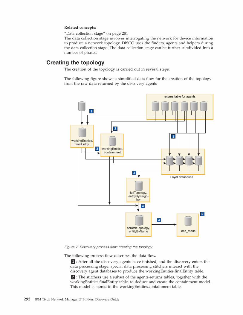
Related concepts:“Data collection stage” on page 281The data collection stage involves interrogating the network for device informationto produce a network topology. DISCO uses the finders, agents and helpers duringthe data collection stage. The data collection stage can be further subdivided into anumber of phases.
Creating the topologyThe creation of the topology is carried out in several steps.
The following figure shows a simplified data flow for the creation of the topologyfrom the raw data returned by the discovery agents
The following process flow describes the data flow.�1�: After all the discovery agents have finished, and the discovery enters thedata processing stage, special data processing stitchers interact with thediscovery agent databases to produce the workingEntities.finalEntity table.�2�: The stitchers use a subset of the agents-returns tables, together with theworkingEntities.finalEntity table, to deduce and create the containment model.This model is stored in the workingEntities.containment table.
1
2
33
4
4
33
2
5
returns table for agents
workingEntities,finalEntity
returns table for agents
workingEntities,containment
Layer databases
fullTopology,entityByNeigh-
bor
scratchTopology,entityByName ncp_model
Figure 7. Discovery process flow: creating the topology
292 IBM Tivoli Network Manager IP Edition: Discovery Guide
�3�: The stitchers use a further subset of the agents-returns tables, together withthe workingEntities.finalEntity table and the workingEntities.containment table,to build the various topology layers, which are stored in the layer databasetables. The full set of layers is merged in the fullTopology.entityByNeighbortable.�4�: The stitchers merge the three tables produced (workingEntities.finalEntity;workingEntities.containment; fullTopology.entityByNeighbor) to build thenetwork model.�5�: The Topology manager, ncp_model, instantiates each network element(subject to the instantiation filter) and sends the topology to other componentsas required.
Related concepts:“Data processing stage” on page 281Topology deduction takes place during the data processing stage, as theinformation from the data collection stage is analyzed, interpreted and processedby the stitchers. The culmination of the data processing stage is the production ofthe containment model.
Broadcast of discovery dataOn completion of a discovery the Topology manager, ncp_model, uses the messagebus to receive topology updates from the discovery and to pass on those updatesto the message bus where other processes like the Event Gateway can retrievethese updates. In addition, ncp_model also uses these updates to update the NCIMtopology database.
Data is stored in two formats:v NCIM cache formatv Legacy master.entityByName format
The purpose of each storage format is as follows:
NCIM cache formatData in this format is used by ncp_model to place updates on the messagebus for other processes such as the Event Gateway, ncp_g_event
Legacy master.entityByName formatData in this format is used by ncp_model to update the NCIM topologydatabase
The NCIM cache format is described in the IBM Tivoli Network Manager IP EditionTopology Database Reference.
Advanced discovery configuration optionsUse this information to understand how to configure the discovery process dataflow and to configure download of full routing tables.
Appendix B. Discovery process 293
Configurable discovery data flowThe discovery process data flow is user-configurable. Stitchers control themovement of data between databases, and you can customize the discoveryprocess by changing the way in which the stitchers are triggered and operate.
Stitcher and agent triggers
You can modify the data flow by changing the criteria that trigger the deploymentof the stitchers and discovery agents, by modifying the stitchers, and, if necessary,by modifying the agent definitions. Some typical triggers are:v Data being inserted into a specific database tablev A stitcher or discovery agent completing its operationv The end of a discovery phase
Any changes you make are automatically detected by DISCO during its periodicscan of the agent and stitcher files (the scan frequency is determined by the entryin the disco.config database). On detecting changes, DISCO modifies its agent andstitcher definitions databases accordingly, and applies the changes to the nextdiscovery cycle.
For more details about the stitchers and the stitcher language, see the IBM TivoliNetwork Manager IP Edition Language Reference Guide.
On-demand stitchers
Stitchers can be started on demand. If you insert a stitcher into the stitchers.actionsdatabase, DISCO automatically runs the stitcher. This means that the discoverycycle can be started at any point, and further actions can be configured to startwhen the stitcher completes.Related reference:“stitchers.actions table” on page 220If a stitcher is inserted into the stitchers.actions table, DISCO runs the stitcher.Once the stitcher has completed, its entry is deleted from the stitchers.actions table.Any stitchers triggered to execute from the stitcher that has been inserted, or uponcompletion of the stitcher, are also executed.
Partial matchingBy default, the discovery process uses partial matching, which means that thediscovery agents do not need to download the full routing tables during discovery.
You do not need to modify the discovery agent definition files to use partialmatching. However, it is possible to prevent the IpForwardingTable andIpRoutingTable discovery agents from using partial matching in certain cases ifyou have devices on your network that do not support partial matching.
To prevent partial matching on certain devices, you must specify the devices thatdo not support partial matching in the DiscoRouterPartialMatchRestrictions();section of the IpForwardingTable.agnt definition file (for modern devices that useRFC2096) or the IpRoutingTable.agnt definition file (for older devices that useRFC1213). If a discovered device matches the filter specified in theDiscoRouterPartialMatchRestrictions(); section, partial matching is notattempted on that device.
294 IBM Tivoli Network Manager IP Edition: Discovery Guide
Discovery process with EMS integrationNetwork Manager collects topology data from an EMS using collectors.
The following steps show how Network Manager collects topology data from anEMS using collectors.
Collector-based discovery can be divided into the following conceptual steps:v Discovering device existencev Discovering basic device informationv Discovering detailed device information
For an overview of how Network Manager collects topology data from ElementManagement Systems (EMSs) and integrates this data into the discovered topology,see the IBM Tivoli Network Manager IP Edition Product Overview.Related concepts:“Discovery cycles” on page 285A discovery cycle has occurred when the discovery data flow for a particular cyclehas gone from start to finish. A full discovery might require more than one cycle.Related tasks:“Configuring EMS discoveries” on page 88You can configure Network Manager to collect topology data from ElementManagement Systems (EMS) and integrate this data into the discovered topology.
Discovering device existence with collectorsDuring a collector discovery, the discovery of device existence takes place inseveral steps.
Figure 8 on page 296 shows how the initial existence of devices held on thecollectors is discovered.
Appendix B. Discovery process 295
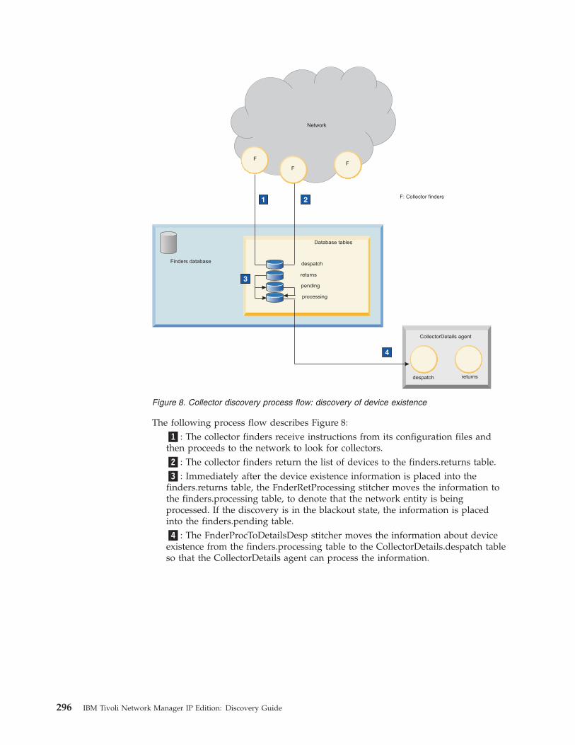
The following process flow describes Figure 8:�1�: The collector finders receive instructions from its configuration files andthen proceeds to the network to look for collectors.�2�: The collector finders return the list of devices to the finders.returns table.�3�: Immediately after the device existence information is placed into thefinders.returns table, the FnderRetProcessing stitcher moves the information tothe finders.processing table, to denote that the network entity is beingprocessed. If the discovery is in the blackout state, the information is placedinto the finders.pending table.�4�: The FnderProcToDetailsDesp stitcher moves the information about deviceexistence from the finders.processing table to the CollectorDetails.despatch tableso that the CollectorDetails agent can process the information.
1 2
33
4
despatch returns
Finders database
Database tables
despatch
returns
pending
processing
F
FF
F: Collector finders
CollectorDetails agent
Network
Figure 8. Collector discovery process flow: discovery of device existence
296 IBM Tivoli Network Manager IP Edition: Discovery Guide
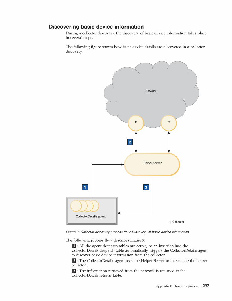
Discovering basic device informationDuring a collector discovery, the discovery of basic device information takes placein several steps.
The following figure shows how basic device details are discovered in a collectordiscovery.
The following process flow describes Figure 9:�1�: All the agent despatch tables are active, so an insertion into theCollectorDetails.despatch table automatically triggers the CollectorDetails agentto discover basic device information from the collector.�2�: The CollectorDetails agent uses the Helper Server to interrogate the helpercollector .�3�: The information retrieved from the network is returned to theCollectorDetails.returns table.
1 33
2
H H
Helper server
Network
CollectorDetails agent
H: Collector
Figure 9. Collector discovery process flow: Discovery of basic device information
Appendix B. Discovery process 297
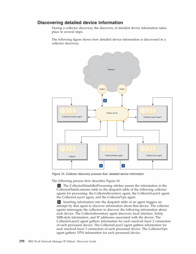
Discovering detailed device informationDuring a collector discovery, the discovery of detailed device information takesplace in several steps.
The following figure shows how detailed device information is discovered in acollector discovery.
The following process flow describes Figure 10:�1�: The CollectorDetailsRetProcessing stitcher passes the information in theCollectorDetails.returns table to the despatch table of the following collectoragents for processing: the CollectorInventory agent, the CollectorLayer2 agent,the CollectorLayer3 agent, and the CollectorVpn agent�2�: Inserting information into the despatch table of an agent triggers anattempt by that agent to discover information about that device. The collectoragents interrogate the collectors to discover the following information abouteach device. The CollectorInventory agent discovers local interface, EntityMIB-style information, and IP addresses associated with the device. TheCollectorLayer2 agent gathers information for each resolved layer 2 connectionof each processed device. The CollectorLayer3 agent gathers information foreach resolved layer 3 connection of each processed device. The CollectorVpnagent gathers VPN information for each processed device.
1
2
1
HelperHelper
Helper server
Network
CollectorInventory agent
CollectorVpn agent
CollectorLayer3 agent
CollectorDetails agentCollecto
Figure 10. Collector discovery process flow: detailed device information
298 IBM Tivoli Network Manager IP Edition: Discovery Guide
RediscoveryWhen a discovery has completed, ncp_disco enters rediscovery mode, in which thediscovery of new devices results in updates to the topology model.
Full and partial rediscoveryBy modifying the stitchers, you can configure the way DISCO treats devices thatare found in the rediscovery mode.
By default, when the system is in rediscovery mode and either a new device isfound or an existing device changes, the device is rediscovered. The stitchersensure that the device is rediscovered only once. The stitchers also check that thechange has not caused the relationship of the device with its neighbors to change.If necessary, the neighbors of the device are rediscovered. If the number of devicesthat need to be rediscovered as a result of relationship changes exceeds a certainlimit, the rediscovery process initiates a full rediscovery.Related concepts:“About types of discovery” on page 1Different terms are used to describe network discovery, depending on what isbeing discovered and how the discovery has been configured. You can rundiscoveries, rediscoveries, full and partial discoveries, and you can set upautomatic discovery.
Process flow of the FnderRetProcessing stitcherTo configure the way in which DISCO handles newly discovered devices, edit theFnderRetProcessing.stch stitcher. This stitcher processes the entries that are placedinto the finders.returns table.
The default process flow of the FnderRetProcessing.stch stitcher is:1. When an entry is placed in the finders.returns table, the stitcher checks whether
the device is in the scope of the discovery. If the device is not in scope, it isignored.
2. If the device is in scope and disco.status.m_DiscoveryMode=0, that is, DISCO isin discovery mode, the stitcher moves the device details to either thefinders.pending table to be processed later (if the discovery is in the blackoutstate) or the finders.processing table to be processed now.
3. If the device is in scope and disco.status.m_DiscoveryMode=1, that is, DISCO isin rediscovery mode, the stitcher determines whether the device needs to berediscovered. By default, the stitcher rediscovers:v Devices for which finders.returns.m_Creator='Rediscovery'. There is no
Rediscovery finder, but this column is set to 'Rediscovery' by other stitchers,such as ProcRemoteConns.stch, to indicate that as a result of rediscoveringother devices this device needs to be rediscovered.
v Any newly found device that is in scope and has not already beendiscovered.
4. If necessary, you can alter the section of the FnderRetProcessing.stch stitcherthat performs the above checks in order to configure when rediscovery of adevice takes place, although this configuration adjustment must be undertakenby advanced users only.
5. If a device that has already been discovered is to be rediscovered, the stitcherrefreshes the information held in the Helper Server that relates to that device.
Appendix B. Discovery process 299
6. For all devices to be rediscovered, the stitcher removes the old entries for thatdevice from the finders.processing, Details.returns and Details.despatch tables,copying the old information to the rediscoveryStore.dataLibrary table forcomparison purposes.
7. The stitcher then places the details of the device to be rediscovered into thefinders.processing table and the FnderProcToDetailsDesp.stch stitcher movesthe device details to the Details agent.
Processing information from discovery agents duringrediscoveryAfter the entity that is being rediscovered has been processed by the Details agent,and the details are placed in the Details.returns table, the DetailsRetProcessing.stchstitcher compares the old data in the rediscoveryStore.dataLibrary table with thenew data. By default, the rediscovery continues from this point.
If necessary, you can edit the DetailsRetProcessing.stch stitcher so that rediscoverycontinues only when certain conditions are in place. For example, rediscoverycontinues only when SNMP access is available.
The rediscovery data is processed by the AssocAddress agent and then by theappropriate agents (according to the configured discovery process flow) and sentto their returns tables.
A full discovery combines the information from the discovery agent returns tablesto produce the topology. However, in a rediscovery, the information must bechecked to determine whether the relationships between devices have changed as aresult of the new information.
For example, if the device being rediscovered, device A, was connected to device Bbefore the rediscovery, but is now connected to a third device, device C, then bothB and C must also be rediscovered because their relationship has changed. TheAgentRetProcessing.stch stitcher determines the relationships between devices andthe comparison is done by ProcRemoteConns.stch. Switches and hubs need to berediscovered differently to routers because the connectivity information theyprovide is indirect instead of direct. Any entity that also needs to be rediscoveredas a consequence of rediscovery is inserted back into the finders.returns table withthe parameter m_Creator='Rediscovery'.
Full rediscoveriesComparing the current relationship between devices to their previous relationship,and rediscovering all the devices whose relationships have changed, can sometimesbecome circular. However, the discovery process includes a check to prevent thisrepetition.
If the ratio of entities that have been compared to the entities that need to berediscovered exceeds the percentage specified in thedisco.config.m_PendingPerCent column, then DISCO stops rediscoveringindividual devices and initiates a full network discovery.
Additionally, the fact that all rediscovered entities are recorded in therediscoveryStore.rediscoveredEntities table means that a given entity can berediscovered only once.
300 IBM Tivoli Network Manager IP Edition: Discovery Guide
Rediscovery completionWhen all the entities that need to be rediscovered have been processed, thetopology layers are rebuilt by the FinalPhase.stch stitcher. This stitcher also clearsthe rediscoveryStore database so that it is ready for the next rediscovery.
It is important to note that DISCO might go through many discovery cycles duringrediscovery before the topology is rebuilt. DISCO rebuilds the topology only whenthere are no entities needing to be rediscovered.
Option to rebuild topology layersYou can specify whether to rebuild the topology layers following a partialrediscovery. Using this option, you can increase the speed of partial rediscovery.
Suggested reasons to rebuild or not to rebuild the topology layers are:v If you specify that the topology layers should not be rebuilt following partial
rediscovery, the result is that new devices are added to the topology much fasterthan they would be if the topology layers are rebuilt; however, the resultingtopology may not be complete. Connectivity associated with the newlydiscovered device is not fully reflected in the topology. Topology layers are fullyrebuilt when a full rediscovery is run.
v If you specify that topology layers should be rebuilt following partial rediscovery,the result is an accurate topology showing all connectivity. However the processof adding new devices takes longer.
Use the m_RebuildLayers field in the disco.config table to specify whether or notto rebuild topology layers following partial rediscovery. You set this value asfollows:v If disco.config.m_RebuildLayers=0, then following partial rediscovery, topology
layers stitchers are not run. The result is a much quicker partial discovery:however, connectivity associated with the newly discovered device is not fullyreflected in the topology.
v If disco.config.m_RebuildLayers=1, then following partial rediscovery, topologylayers stitchers are run. Partial rediscovery takes longer but results in a completetopology.
Appendix B. Discovery process 301

302 IBM Tivoli Network Manager IP Edition: Discovery Guide
Appendix C. Discovery agents
Use this information to support the selection of discovery agents to run as part ofyour discovery.
The following topics provide information on the discovery agents available. Thereis also guidance on the agents to select, based on the characteristics of yournetwork.
AgentsDiscovery agents retrieve information about devices in the network. They alsoreport on new devices by finding new connections when investigating deviceconnectivity. Discovery agents are used for specialized tasks. For example, the ARPCache discovery agent populates the Helper Server database with IPaddress-to-MAC address mappings.
In addition to the main discovery agents, which can be enabled or disabledaccording to your discovery requirements, there are two agents that must alwaysbe run: the Details agent and the Associated Address agent.
Each discovery agent has its own database resident within DISCO. These databasesare generically structured and based on a template called the agentTemplatedatabase.
Each discovery agent database contains the following tables:v agentName.despatch
v agentName.returns
Note: The default configuration sets the majority of agents to run. This is becausethe more agents that are run, the wider the range of networks that can bediscovered. Furthermore, agents are designed to quickly stop analyzing devicesthat do not provide the data they require. This means that running a large numberof agents increases network traffic by a very small amount only.
Note: Network Manager kills all discovery agents at the end of data collectionstage 3. This ensures that the next discovery restarts the agents and forces theagents to reread their configuration files at the beginning of a discovery, therebydetecting any changes to the configuration files.Related reference:“Subprocess databases” on page 220The finders, Details, and agent databases are used during the discovery by thediscovery engine subprocesses to store information retrieved from the network.The databases are defined within the configuration file, DiscoSchema.cfg.“DiscoAgentReturns.filter configuration file” on page 55The DiscoAgentReturns.filter configuration file allows you to apply a topologydata filter to data returned by all discovery agents.
© Copyright IBM Corp. 2006, 2013 303
Details agentThis agent is triggered by the entries in the finders.processing table. At least onefinder is needed to activate this agent. The SNMP helper configuration forassociated devices is also a prerequisite for running this agent.
The Details agent retrieves basic information about devices discovered by thefinders, and determines whether SNMP access to the device is available. Thismandatory agent is triggered by the entries in the finders.processing table, so atleast one finder is needed to activate this agent.
The Details agent is triggered when device information (usually transferred fromthe finders by a stitcher) is placed in the Details.despatch database table.
The Details agent retrieves basic information from the network and deposits thisinformation in the Details.returns table. The basic information retrievedcomprises the DNS name of the device obtained by the configured DNS helper,and the system object ID obtained by the SNMP helper. IpForwarding data isdownloaded and inserted into the ExtraInfo field which is used to identify routingdevices. SysName information is also downloaded for use if this optional namingscheme is required. The insertion of data into the returns table triggers a stitcherthat sends this information to the Associated Address agent.Related concepts:“Discovering device details (standard)” on page 287The standard discovery of device details is carried out in several steps.
Associated Address (AssocAddress) agentThis mandatory agent is triggered by the output of the Details agent. The SNMPhelper configuration for associated devices is a prerequisite for running this agent.
When an interface on a device has been discovered, and basic device informationhas been retrieved by the Details agent, a stitcher passes the discovered deviceinformation to the Associated Address agent. This agent downloads all the other IPaddresses associated with the device and adds them to a central registry, held inthe translations.ipToBaseName table, provided the device details are not alreadyin the registry. Downloading all the associated IP addresses ensures that any givendevice is only interrogated once by the main discovery agents, thus reducing theload on the agents. Any attempt to discover a device more than once (usingmultiple interfaces) is blocked by the Associated Address agent as the devicedetails are already in the translations database.
Provided the device being checked has not already been discovered, a stitchersends the device details to the appropriate discovery agent for the retrieval ofdevice connectivity and protocol-specific information.Related concepts:“Discovering associated device addresses” on page 289There are several steps in the process flow during the discovery of associateddevice addresses.
304 IBM Tivoli Network Manager IP Edition: Discovery Guide
Interface data retrieved by agentsThe Interfaces agent downloads interface information from the interfaces table ofRFC1213.mib. For each device discovered, the interface information is written tothe m_LocalNbr field within each record in the relevant agent.returns table.
The Interfaces agent downloads interface information primarily from the interfacestable of RFC1213.mib. For each device discovered, the interface information iswritten to the m_LocalNbr field within each record in the relevant agent.returnstable. The interface information can hold a number of subfields, including an indexnumber that identifies the interface together with the properties of that interfaceand values for each property. For example, the m_LocalNbr field may include thefollowing subfields:v m_LocalNbr->m_IfIndex: the index associated with this interfacev m_LocalNbr->m_IfType: the type of interfacev m_LocalNbr->m_SubnetMask: the subnet mask of the interfaceRelated reference:“Connectivity at the layer 3 network layer” on page 316There are a number of discovery agents that retrieve connectivity information fromOSI model layer 3 (the Network Layer). Layer 3 is responsible for routing,congestion control, and sending messages between networks.
Discovery agent definition file keywordsDiscovery agent definition file keywords are used to define the operation ofdiscovery agents.
DiscoAgentClass
The DiscoAgentClass keyword specifies the basic type of agent. The following tableidentifies the most commonly used values:
Value Description
0 Specifies an IP type agent.
1 Specifies a switch type agent.
2 Specifies a hub type agent.
3 Specifies an ATM device type agent.
4 Specifies an FDDI type agent.
5 Specifies a PVC type agent.
6 Specifies a frame relay type agent.
8 Specifies a NAT gateway agent.
The following example shows a DiscoAgentClass keyword set to a frame relaytype agent. Frame relay type agents typically discover Frame Relay interfaces andconnections between two points on Frame Relay networks that incorporate specificnetwork devices, for example, CISCO devices.DiscoCompiledAgent{...DiscoAgentClass( 6 );
Appendix C. Discovery agents 305
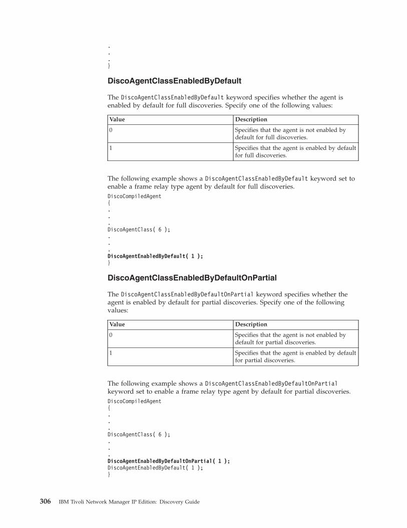
.
.
.}
DiscoAgentClassEnabledByDefault
The DiscoAgentClassEnabledByDefault keyword specifies whether the agent isenabled by default for full discoveries. Specify one of the following values:
Value Description
0 Specifies that the agent is not enabled bydefault for full discoveries.
1 Specifies that the agent is enabled by defaultfor full discoveries.
The following example shows a DiscoAgentClassEnabledByDefault keyword set toenable a frame relay type agent by default for full discoveries.DiscoCompiledAgent{...DiscoAgentClass( 6 );...DiscoAgentEnabledByDefault( 1 );}
DiscoAgentClassEnabledByDefaultOnPartial
The DiscoAgentClassEnabledByDefaultOnPartial keyword specifies whether theagent is enabled by default for partial discoveries. Specify one of the followingvalues:
Value Description
0 Specifies that the agent is not enabled bydefault for partial discoveries.
1 Specifies that the agent is enabled by defaultfor partial discoveries.
The following example shows a DiscoAgentClassEnabledByDefaultOnPartialkeyword set to enable a frame relay type agent by default for partial discoveries.DiscoCompiledAgent{...DiscoAgentClass( 6 );...DiscoAgentEnabledByDefaultOnPartial( 1 );DiscoAgentEnabledByDefault( 1 );}
306 IBM Tivoli Network Manager IP Edition: Discovery Guide
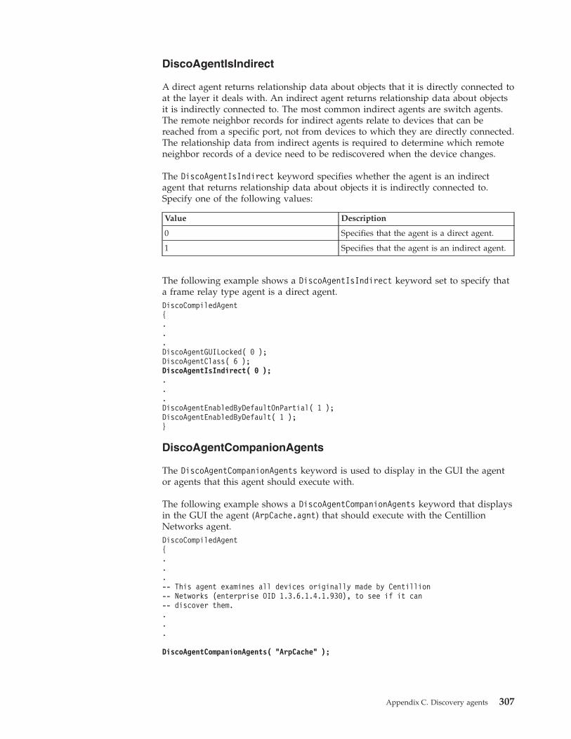
DiscoAgentIsIndirect
A direct agent returns relationship data about objects that it is directly connected toat the layer it deals with. An indirect agent returns relationship data about objectsit is indirectly connected to. The most common indirect agents are switch agents.The remote neighbor records for indirect agents relate to devices that can bereached from a specific port, not from devices to which they are directly connected.The relationship data from indirect agents is required to determine which remoteneighbor records of a device need to be rediscovered when the device changes.
The DiscoAgentIsIndirect keyword specifies whether the agent is an indirectagent that returns relationship data about objects it is indirectly connected to.Specify one of the following values:
Value Description
0 Specifies that the agent is a direct agent.
1 Specifies that the agent is an indirect agent.
The following example shows a DiscoAgentIsIndirect keyword set to specify thata frame relay type agent is a direct agent.DiscoCompiledAgent{...DiscoAgentGUILocked( 0 );DiscoAgentClass( 6 );DiscoAgentIsIndirect( 0 );...DiscoAgentEnabledByDefaultOnPartial( 1 );DiscoAgentEnabledByDefault( 1 );}
DiscoAgentCompanionAgents
The DiscoAgentCompanionAgents keyword is used to display in the GUI the agentor agents that this agent should execute with.
The following example shows a DiscoAgentCompanionAgents keyword that displaysin the GUI the agent (ArpCache.agnt) that should execute with the CentillionNetworks agent.DiscoCompiledAgent{...-- This agent examines all devices originally made by Centillion-- Networks (enterprise OID 1.3.6.1.4.1.930), to see if it can-- discover them....
DiscoAgentCompanionAgents( "ArpCache" );
Appendix C. Discovery agents 307
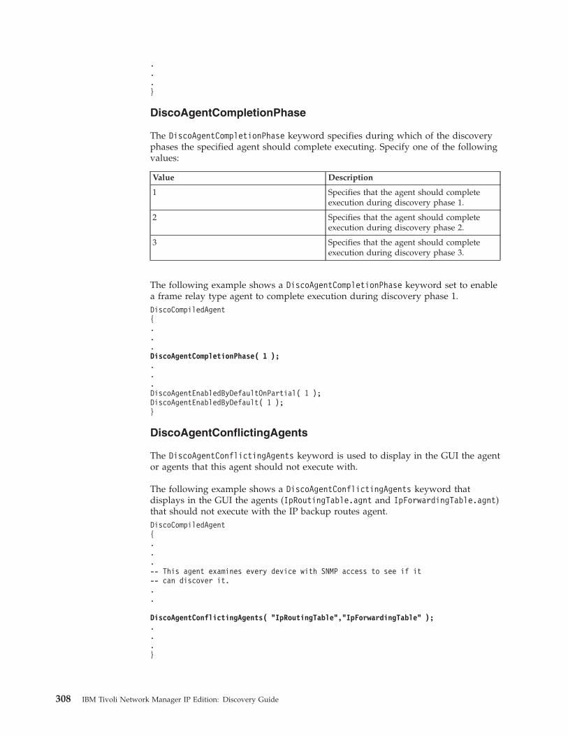
.
.
.}
DiscoAgentCompletionPhase
The DiscoAgentCompletionPhase keyword specifies during which of the discoveryphases the specified agent should complete executing. Specify one of the followingvalues:
Value Description
1 Specifies that the agent should completeexecution during discovery phase 1.
2 Specifies that the agent should completeexecution during discovery phase 2.
3 Specifies that the agent should completeexecution during discovery phase 3.
The following example shows a DiscoAgentCompletionPhase keyword set to enablea frame relay type agent to complete execution during discovery phase 1.DiscoCompiledAgent{...DiscoAgentCompletionPhase( 1 );...DiscoAgentEnabledByDefaultOnPartial( 1 );DiscoAgentEnabledByDefault( 1 );}
DiscoAgentConflictingAgents
The DiscoAgentConflictingAgents keyword is used to display in the GUI the agentor agents that this agent should not execute with.
The following example shows a DiscoAgentConflictingAgents keyword thatdisplays in the GUI the agents (IpRoutingTable.agnt and IpForwardingTable.agnt)that should not execute with the IP backup routes agent.DiscoCompiledAgent{...-- This agent examines every device with SNMP access to see if it-- can discover it...
DiscoAgentConflictingAgents( "IpRoutingTable","IpForwardingTable" );...}
308 IBM Tivoli Network Manager IP Edition: Discovery Guide
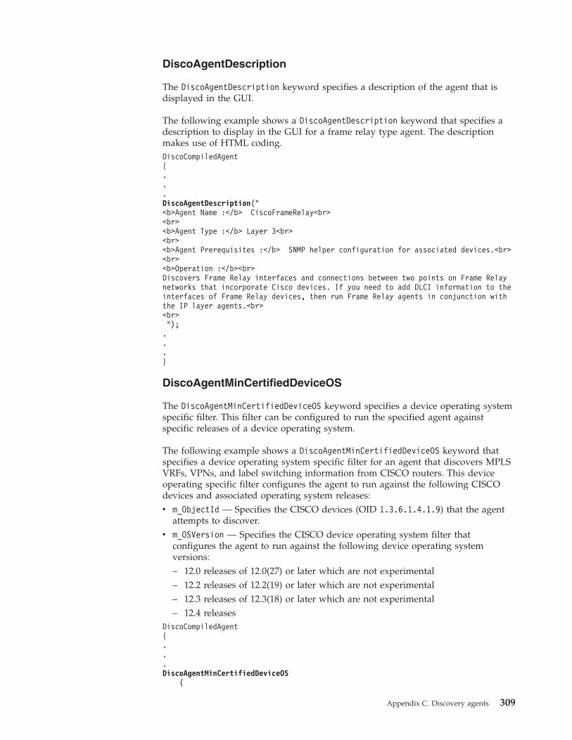
DiscoAgentDescription
The DiscoAgentDescription keyword specifies a description of the agent that isdisplayed in the GUI.
The following example shows a DiscoAgentDescription keyword that specifies adescription to display in the GUI for a frame relay type agent. The descriptionmakes use of HTML coding.DiscoCompiledAgent{...DiscoAgentDescription("<b>Agent Name :</b> CiscoFrameRelay<br><br><b>Agent Type :</b> Layer 3<br><br><b>Agent Prerequisites :</b> SNMP helper configuration for associated devices.<br><br><b>Operation :</b><br>Discovers Frame Relay interfaces and connections between two points on Frame Relaynetworks that incorporate Cisco devices. If you need to add DLCI information to theinterfaces of Frame Relay devices, then run Frame Relay agents in conjunction withthe IP layer agents.<br><br>");...}
DiscoAgentMinCertifiedDeviceOS
The DiscoAgentMinCertifiedDeviceOS keyword specifies a device operating systemspecific filter. This filter can be configured to run the specified agent againstspecific releases of a device operating system.
The following example shows a DiscoAgentMinCertifiedDeviceOS keyword thatspecifies a device operating system specific filter for an agent that discovers MPLSVRFs, VPNs, and label switching information from CISCO routers. This deviceoperating specific filter configures the agent to run against the following CISCOdevices and associated operating system releases:v m_ObjectId — Specifies the CISCO devices (OID 1.3.6.1.4.1.9) that the agent
attempts to discover.v m_OSVersion — Specifies the CISCO device operating system filter that
configures the agent to run against the following device operating systemversions:– 12.0 releases of 12.0(27) or later which are not experimental– 12.2 releases of 12.2(19) or later which are not experimental– 12.3 releases of 12.3(18) or later which are not experimental– 12.4 releases
DiscoCompiledAgent{...DiscoAgentMinCertifiedDeviceOS
(
Appendix C. Discovery agents 309
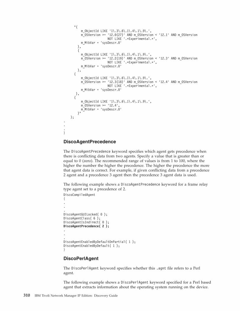
"(m_ObjectId LIKE ’1\.3\.6\.1\.4\.1\.9\.’,m_OSVersion >= ’12.0(27)’ AND m_OSVersion < ’12.1’ AND m_OSVersion
NOT LIKE ’.*Experimental.*’,m_MibVar = ’sysDescr.0’
),(
m_ObjectId LIKE ’1\.3\.6\.1\.4\.1\.9\.’,m_OSVersion >= ’12.2(19)’ AND m_OSVersion < ’12.3’ AND m_OSVersion
NOT LIKE ’.*Experimental.*’,m_MibVar = ’sysDescr.0’
),(
m_ObjectId LIKE ’1\.3\.6\.1\.4\.1\.9\.’,m_OSVersion >= ’12.3(18)’ AND m_OSVersion < ’12.4’ AND m_OSVersion
NOT LIKE ’.*Experimental.*’,m_MibVar = ’sysDescr.0’
),(
m_ObjectId LIKE ’1\.3\.6\.1\.4\.1\.9\.’,m_OSVersion >= ’12.4’,m_MibVar = ’sysDescr.0’
)");
.
.
.}
DiscoAgentPrecedence
The DiscoAgentPrecedence keyword specifies which agent gets precedence whenthere is conflicting data from two agents. Specify a value that is greater than orequal to 0 (zero). The recommended range of values is from 1 to 100, where thehigher the number the higher the precedence. The higher the precedence the morethat agent data is correct. For example, if given conflicting data from a precedence2 agent and a precedence 3 agent then the precedence 3 agent data is used.
The following example shows a DiscoAgentPrecedence keyword for a frame relaytype agent set to a precedence of 2.DiscoCompiledAgent{...DiscoAgentGUILocked( 0 );DiscoAgentClass( 6 );DiscoAgentIsIndirect( 0 );DiscoAgentPrecedence( 2 );...DiscoAgentEnabledByDefaultOnPartial( 1 );DiscoAgentEnabledByDefault( 1 );}
DiscoPerlAgent
The DiscoPerlAgent keyword specifies whether this .agnt file refers to a Perlagent.
The following example shows a DiscoPerlAgent keyword specified for a Perl basedagent that extracts information about the operating system running on the device.
310 IBM Tivoli Network Manager IP Edition: Discovery Guide
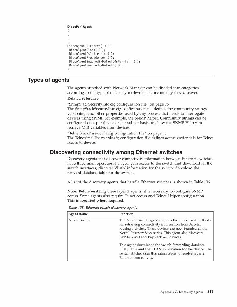
DiscoPerlAgent{...DiscoAgentGUILocked( 0 );DiscoAgentClass( 0 );DiscoAgentIsIndirect( 0 );DiscoAgentPrecedence( 2 );DiscoAgentEnabledByDefaultOnPartial( 0 );DiscoAgentEnabledByDefault( 0 );}
Types of agentsThe agents supplied with Network Manager can be divided into categoriesaccording to the type of data they retrieve or the technology they discover.Related reference:“SnmpStackSecurityInfo.cfg configuration file” on page 75The SnmpStackSecurityInfo.cfg configuration file defines the community strings,versioning, and other properties used by any process that needs to interrogatedevices using SNMP, for example, the SNMP helper. Community strings can beconfigured on a per-device or per-subnet basis, to allow the SNMP Helper toretrieve MIB variables from devices.“TelnetStackPasswords.cfg configuration file” on page 78The TelnetStackPasswords.cfg configuration file defines access credentials for Telnetaccess to devices.
Discovering connectivity among Ethernet switchesDiscovery agents that discover connectivity information between Ethernet switcheshave three main operational stages: gain access to the switch and download all theswitch interfaces; discover VLAN information for the switch; download theforward database table for the switch.
A list of the discovery agents that handle Ethernet switches is shown in Table 136.
Note: Before enabling these layer 2 agents, it is necessary to configure SNMPaccess. Some agents also require Telnet access and Telnet Helper configuration.This is specified where required.
Table 136. Ethernet switch discovery agents
Agent name Function
AccelarSwitch The AccelarSwitch agent contains the specialized methodsfor retrieving connectivity information from Accelarrouting switches. These devices are now branded as theNortel Passport 86xx series. This agent also discoversBayStack 450 and BayStack 470 devices.
This agent downloads the switch forwarding database(FDB) table and the VLAN information for the device. Theswitch stitcher uses this information to resolve layer 2Ethernet connectivity.
Appendix C. Discovery agents 311
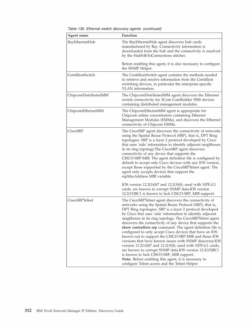
Table 136. Ethernet switch discovery agents (continued)
Agent name Function
BayEthernetHub The BayEthernetHub agent discovers hub cardsmanufactured by Bay. Connectivity information isdownloaded from the hub and the connectivity is resolvedby the HubFdbToConnections stitcher.
Before enabling this agent, it is also necessary to configurethe SNMP Helper.
CentillionSwitch The CentillionSwitch agent contains the methods neededto retrieve and resolve information from the Centillionswitching devices, in particular the enterprise-specificVLAN information.
ChipcomDistributedMM The ChipcomDistributedMM agent discovers the Ethernetswitch connectivity for 3Com CoreBuilder 5000 devicescontaining distributed management modules.
ChipcomEthernetMM The ChipcomEthernetMM agent is appropriate forChipcom online concentrators containing EthernetManagement Modules (EMMs), and discovers the Ethernetconnectivity of Chipcom EMMs.
CiscoSRP The CiscoSRP agent discovers the connectivity of networksusing the Spatial Reuse Protocol (SRP), that is, DPT Ringtopologies. SRP is a layer 2 protocol developed by Ciscothat uses ‘side' information to identify adjacent neighboursin its ring topology.The CiscoSRP agent discoversconnectivity of any device that supports theCISCO-SRP-MIB. The agent definition file is configured bydefault to accept only Cisco devices with any IOS version,except those supported by the CiscoSRPTelnet agent. Theagent only accepts devices that support thesrpMacAddress MIB variable.
IOS version 12.2(14)S7 and 12.2(18)S, used with NPE-G1cards, are known to corrupt SNMP data.IOS version12.2(15)BC1 is known to lack CISCO-SRP_MIB support.
CiscoSRPTelnet The CiscoSRPTelnet agent discovers the connectivity ofnetworks using the Spatial Reuse Protocol (SRP), that is,DPT Ring topologies. SRP is a layer 2 protocol developedby Cisco that uses ‘side' information to identify adjacentneighbours in its ring topology. The CiscoSRPTelnet agentdiscovers the connectivity of any device that supports theshow controllers srp command. The agent definition file isconfigured to only accept Cisco devices that have an IOSknown not to support the CISCO-SRP-MIB and those IOSversions that have known issues with SNMP discovery.IOSversion 12.2(14)S7 and 12.2(18)S, used with NPE-G1 cards,are known to corrupt SNMP data.IOS version 12.2(15)BC1is known to lack CISCO-SRP_MIB support.Note: Before enabling this agent, it is necessary toconfigure Telnet access and the Telnet Helper.
312 IBM Tivoli Network Manager IP Edition: Discovery Guide
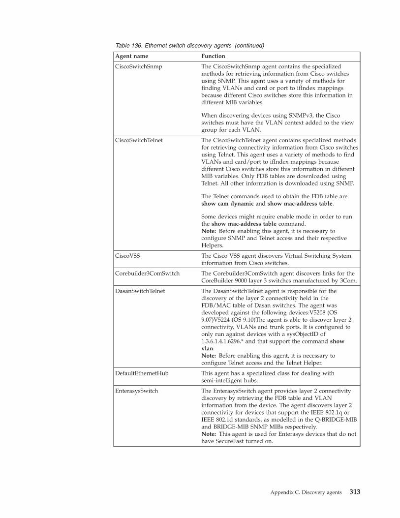
Table 136. Ethernet switch discovery agents (continued)
Agent name Function
CiscoSwitchSnmp The CiscoSwitchSnmp agent contains the specializedmethods for retrieving information from Cisco switchesusing SNMP. This agent uses a variety of methods forfinding VLANs and card or port to ifIndex mappingsbecause different Cisco switches store this information indifferent MIB variables.
When discovering devices using SNMPv3, the Ciscoswitches must have the VLAN context added to the viewgroup for each VLAN.
CiscoSwitchTelnet The CiscoSwitchTelnet agent contains specialized methodsfor retrieving connectivity information from Cisco switchesusing Telnet. This agent uses a variety of methods to findVLANs and card/port to ifIndex mappings becausedifferent Cisco switches store this information in differentMIB variables. Only FDB tables are downloaded usingTelnet. All other information is downloaded using SNMP.
The Telnet commands used to obtain the FDB table areshow cam dynamic and show mac-address table.
Some devices might require enable mode in order to runthe show mac-address table command.Note: Before enabling this agent, it is necessary toconfigure SNMP and Telnet access and their respectiveHelpers.
CiscoVSS The Cisco VSS agent discovers Virtual Switching Systeminformation from Cisco switches.
Corebuilder3ComSwitch The Corebuilder3ComSwitch agent discovers links for theCoreBuilder 9000 layer 3 switches manufactured by 3Com.
DasanSwitchTelnet The DasanSwitchTelnet agent is responsible for thediscovery of the layer 2 connectivity held in theFDB/MAC table of Dasan switches. The agent wasdeveloped against the following devices:V5208 (OS9.07)V5224 (OS 9.10)The agent is able to discover layer 2connectivity, VLANs and trunk ports. It is configured toonly run against devices with a sysObjectID of1.3.6.1.4.1.6296.* and that support the command showvlan.Note: Before enabling this agent, it is necessary toconfigure Telnet access and the Telnet Helper.
DefaultEthernetHub This agent has a specialized class for dealing withsemi-intelligent hubs.
EnterasysSwitch The EnterasysSwitch agent provides layer 2 connectivitydiscovery by retrieving the FDB table and VLANinformation from the device. The agent discovers layer 2connectivity for devices that support the IEEE 802.1q orIEEE 802.1d standards, as modelled in the Q-BRIDGE-MIBand BRIDGE-MIB SNMP MIBs respectively.Note: This agent is used for Enterasys devices that do nothave SecureFast turned on.
Appendix C. Discovery agents 313
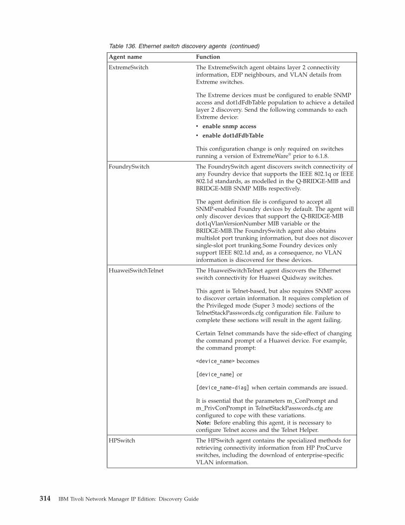
Table 136. Ethernet switch discovery agents (continued)
Agent name Function
ExtremeSwitch The ExtremeSwitch agent obtains layer 2 connectivityinformation, EDP neighbours, and VLAN details fromExtreme switches.
The Extreme devices must be configured to enable SNMPaccess and dot1dFdbTable population to achieve a detailedlayer 2 discovery. Send the following commands to eachExtreme device:
v enable snmp access
v enable dot1dFdbTable
This configuration change is only required on switchesrunning a version of ExtremeWare® prior to 6.1.8.
FoundrySwitch The FoundrySwitch agent discovers switch connectivity ofany Foundry device that supports the IEEE 802.1q or IEEE802.1d standards, as modelled in the Q-BRIDGE-MIB andBRIDGE-MIB SNMP MIBs respectively.
The agent definition file is configured to accept allSNMP-enabled Foundry devices by default. The agent willonly discover devices that support the Q-BRIDGE-MIBdot1qVlanVersionNumber MIB variable or theBRIDGE-MIB.The FoundrySwitch agent also obtainsmultislot port trunking information, but does not discoversingle-slot port trunking.Some Foundry devices onlysupport IEEE 802.1d and, as a consequence, no VLANinformation is discovered for these devices.
HuaweiSwitchTelnet The HuaweiSwitchTelnet agent discovers the Ethernetswitch connectivity for Huawei Quidway switches.
This agent is Telnet-based, but also requires SNMP accessto discover certain information. It requires completion ofthe Privileged mode (Super 3 mode) sections of theTelnetStackPasswords.cfg configuration file. Failure tocomplete these sections will result in the agent failing.
Certain Telnet commands have the side-effect of changingthe command prompt of a Huawei device. For example,the command prompt:
<device_name> becomes
[device_name] or
[device_name-diag] when certain commands are issued.
It is essential that the parameters m_ConPrompt andm_PrivConPrompt in TelnetStackPasswords.cfg areconfigured to cope with these variations.Note: Before enabling this agent, it is necessary toconfigure Telnet access and the Telnet Helper.
HPSwitch The HPSwitch agent contains the specialized methods forretrieving connectivity information from HP ProCurveswitches, including the download of enterprise-specificVLAN information.
314 IBM Tivoli Network Manager IP Edition: Discovery Guide
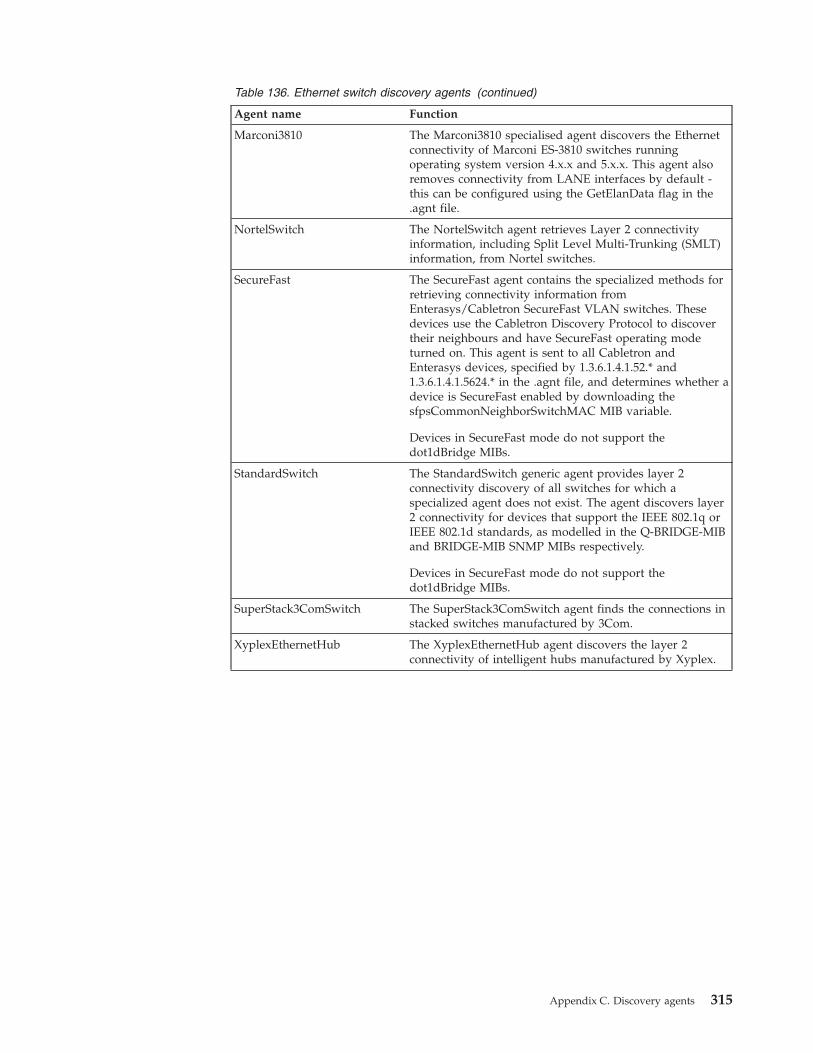
Table 136. Ethernet switch discovery agents (continued)
Agent name Function
Marconi3810 The Marconi3810 specialised agent discovers the Ethernetconnectivity of Marconi ES-3810 switches runningoperating system version 4.x.x and 5.x.x. This agent alsoremoves connectivity from LANE interfaces by default -this can be configured using the GetElanData flag in the.agnt file.
NortelSwitch The NortelSwitch agent retrieves Layer 2 connectivityinformation, including Split Level Multi-Trunking (SMLT)information, from Nortel switches.
SecureFast The SecureFast agent contains the specialized methods forretrieving connectivity information fromEnterasys/Cabletron SecureFast VLAN switches. Thesedevices use the Cabletron Discovery Protocol to discovertheir neighbours and have SecureFast operating modeturned on. This agent is sent to all Cabletron andEnterasys devices, specified by 1.3.6.1.4.1.52.* and1.3.6.1.4.1.5624.* in the .agnt file, and determines whether adevice is SecureFast enabled by downloading thesfpsCommonNeighborSwitchMAC MIB variable.
Devices in SecureFast mode do not support thedot1dBridge MIBs.
StandardSwitch The StandardSwitch generic agent provides layer 2connectivity discovery of all switches for which aspecialized agent does not exist. The agent discovers layer2 connectivity for devices that support the IEEE 802.1q orIEEE 802.1d standards, as modelled in the Q-BRIDGE-MIBand BRIDGE-MIB SNMP MIBs respectively.
Devices in SecureFast mode do not support thedot1dBridge MIBs.
SuperStack3ComSwitch The SuperStack3ComSwitch agent finds the connections instacked switches manufactured by 3Com.
XyplexEthernetHub The XyplexEthernetHub agent discovers the layer 2connectivity of intelligent hubs manufactured by Xyplex.
Appendix C. Discovery agents 315
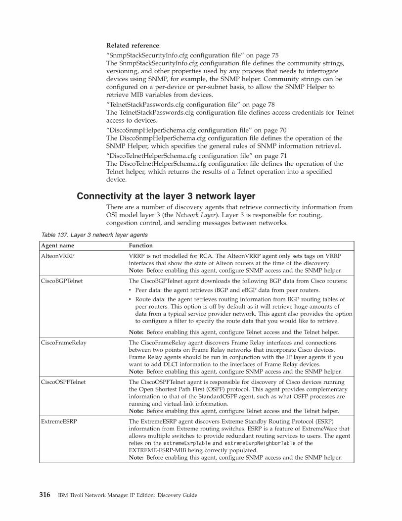
Related reference:“SnmpStackSecurityInfo.cfg configuration file” on page 75The SnmpStackSecurityInfo.cfg configuration file defines the community strings,versioning, and other properties used by any process that needs to interrogatedevices using SNMP, for example, the SNMP helper. Community strings can beconfigured on a per-device or per-subnet basis, to allow the SNMP Helper toretrieve MIB variables from devices.“TelnetStackPasswords.cfg configuration file” on page 78The TelnetStackPasswords.cfg configuration file defines access credentials for Telnetaccess to devices.“DiscoSnmpHelperSchema.cfg configuration file” on page 70The DiscoSnmpHelperSchema.cfg configuration file defines the operation of theSNMP Helper, which specifies the general rules of SNMP information retrieval.“DiscoTelnetHelperSchema.cfg configuration file” on page 71The DiscoTelnetHelperSchema.cfg configuration file defines the operation of theTelnet helper, which returns the results of a Telnet operation into a specifieddevice.
Connectivity at the layer 3 network layerThere are a number of discovery agents that retrieve connectivity information fromOSI model layer 3 (the Network Layer). Layer 3 is responsible for routing,congestion control, and sending messages between networks.
Table 137. Layer 3 network layer agents
Agent name Function
AlteonVRRP VRRP is not modelled for RCA. The AlteonVRRP agent only sets tags on VRRPinterfaces that show the state of Alteon routers at the time of the discovery.Note: Before enabling this agent, configure SNMP access and the SNMP helper.
CiscoBGPTelnet The CiscoBGPTelnet agent downloads the following BGP data from Cisco routers:
v Peer data: the agent retrieves iBGP and eBGP data from peer routers.
v Route data: the agent retrieves routing information from BGP routing tables ofpeer routers. This option is off by default as it will retrieve huge amounts ofdata from a typical service provider network. This agent also provides the optionto configure a filter to specify the route data that you would like to retrieve.
Note: Before enabling this agent, configure Telnet access and the Telnet helper.
CiscoFrameRelay The CiscoFrameRelay agent discovers Frame Relay interfaces and connectionsbetween two points on Frame Relay networks that incorporate Cisco devices.Frame Relay agents should be run in conjunction with the IP layer agents if youwant to add DLCI information to the interfaces of Frame Relay devices.Note: Before enabling this agent, configure SNMP access and the SNMP helper.
CiscoOSPFTelnet The CiscoOSPFTelnet agent is responsible for discovery of Cisco devices runningthe Open Shortest Path First (OSPF) protocol. This agent provides complementaryinformation to that of the StandardOSPF agent, such as what OSFP processes arerunning and virtual-link information.Note: Before enabling this agent, configure Telnet access and the Telnet helper.
ExtremeESRP The ExtremeESRP agent discovers Extreme Standby Routing Protocol (ESRP)information from Extreme routing switches. ESRP is a feature of ExtremeWare thatallows multiple switches to provide redundant routing services to users. The agentrelies on the extremeEsrpTable and extremeEsrpNeighborTable of theEXTREME-ESRP-MIB being correctly populated.Note: Before enabling this agent, configure SNMP access and the SNMP helper.
316 IBM Tivoli Network Manager IP Edition: Discovery Guide
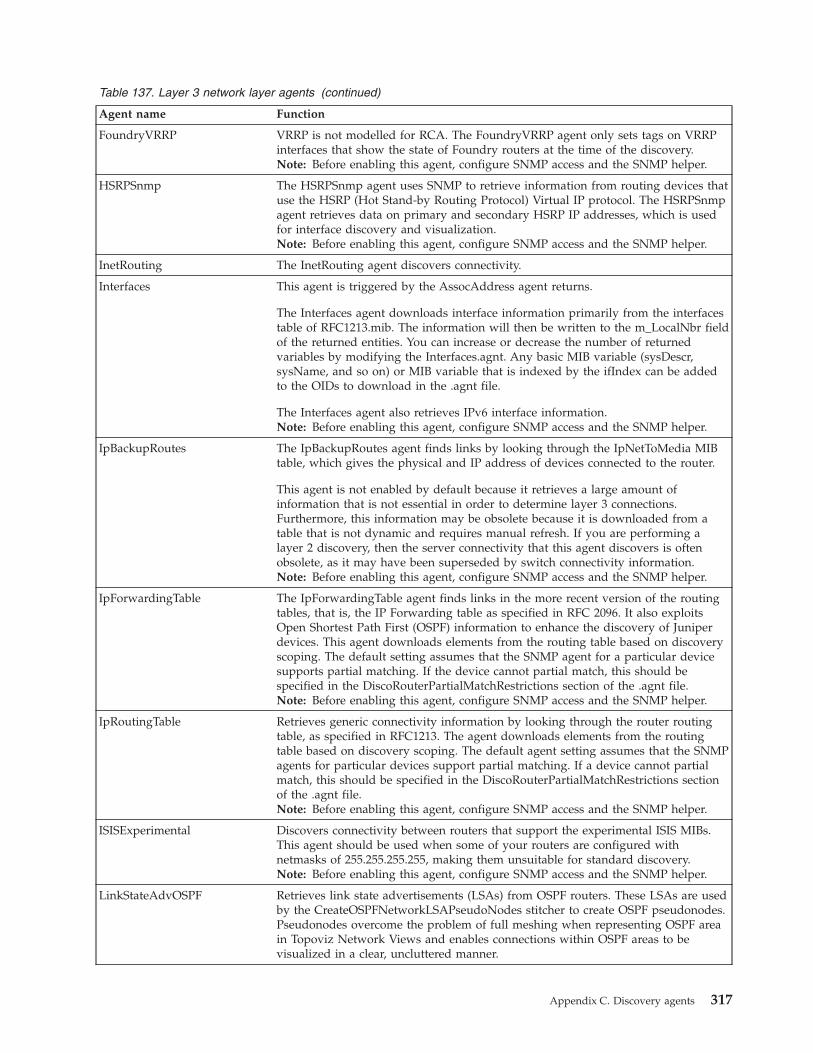
Table 137. Layer 3 network layer agents (continued)
Agent name Function
FoundryVRRP VRRP is not modelled for RCA. The FoundryVRRP agent only sets tags on VRRPinterfaces that show the state of Foundry routers at the time of the discovery.Note: Before enabling this agent, configure SNMP access and the SNMP helper.
HSRPSnmp The HSRPSnmp agent uses SNMP to retrieve information from routing devices thatuse the HSRP (Hot Stand-by Routing Protocol) Virtual IP protocol. The HSRPSnmpagent retrieves data on primary and secondary HSRP IP addresses, which is usedfor interface discovery and visualization.Note: Before enabling this agent, configure SNMP access and the SNMP helper.
InetRouting The InetRouting agent discovers connectivity.
Interfaces This agent is triggered by the AssocAddress agent returns.
The Interfaces agent downloads interface information primarily from the interfacestable of RFC1213.mib. The information will then be written to the m_LocalNbr fieldof the returned entities. You can increase or decrease the number of returnedvariables by modifying the Interfaces.agnt. Any basic MIB variable (sysDescr,sysName, and so on) or MIB variable that is indexed by the ifIndex can be addedto the OIDs to download in the .agnt file.
The Interfaces agent also retrieves IPv6 interface information.Note: Before enabling this agent, configure SNMP access and the SNMP helper.
IpBackupRoutes The IpBackupRoutes agent finds links by looking through the IpNetToMedia MIBtable, which gives the physical and IP address of devices connected to the router.
This agent is not enabled by default because it retrieves a large amount ofinformation that is not essential in order to determine layer 3 connections.Furthermore, this information may be obsolete because it is downloaded from atable that is not dynamic and requires manual refresh. If you are performing alayer 2 discovery, then the server connectivity that this agent discovers is oftenobsolete, as it may have been superseded by switch connectivity information.Note: Before enabling this agent, configure SNMP access and the SNMP helper.
IpForwardingTable The IpForwardingTable agent finds links in the more recent version of the routingtables, that is, the IP Forwarding table as specified in RFC 2096. It also exploitsOpen Shortest Path First (OSPF) information to enhance the discovery of Juniperdevices. This agent downloads elements from the routing table based on discoveryscoping. The default setting assumes that the SNMP agent for a particular devicesupports partial matching. If the device cannot partial match, this should bespecified in the DiscoRouterPartialMatchRestrictions section of the .agnt file.Note: Before enabling this agent, configure SNMP access and the SNMP helper.
IpRoutingTable Retrieves generic connectivity information by looking through the router routingtable, as specified in RFC1213. The agent downloads elements from the routingtable based on discovery scoping. The default agent setting assumes that the SNMPagents for particular devices support partial matching. If a device cannot partialmatch, this should be specified in the DiscoRouterPartialMatchRestrictions sectionof the .agnt file.Note: Before enabling this agent, configure SNMP access and the SNMP helper.
ISISExperimental Discovers connectivity between routers that support the experimental ISIS MIBs.This agent should be used when some of your routers are configured withnetmasks of 255.255.255.255, making them unsuitable for standard discovery.Note: Before enabling this agent, configure SNMP access and the SNMP helper.
LinkStateAdvOSPF Retrieves link state advertisements (LSAs) from OSPF routers. These LSAs are usedby the CreateOSPFNetworkLSAPseudoNodes stitcher to create OSPF pseudonodes.Pseudonodes overcome the problem of full meshing when representing OSPF areain Topoviz Network Views and enables connections within OSPF areas to bevisualized in a clear, uncluttered manner.
Appendix C. Discovery agents 317
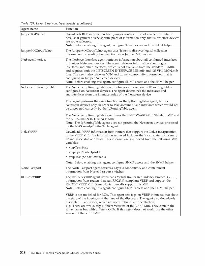
Table 137. Layer 3 network layer agents (continued)
Agent name Function
JuniperBGPTelnet Downloads BGP information from Juniper routers. It is not enabled by defaultbecause it gathers a very specific piece of information only, that is, whether devicesare route reflectors.Note: Before enabling this agent, configure Telnet access and the Telnet helper.
JuniperMXGroupTelnet The JuniperMXGroupTelnet agent uses Telnet to discover logical collectioninformation for Routing Engine Groups on Juniper MX devices.
NetScreenInterface The NetScreenInterface agent retrieves information about all configured interfacesin Juniper Netscreen devices. The agent retrieves information about logicalinterfaces and other interfaces, which is not available from the standard IF-MIB,and requires both the NETSCREEN-INTERFACE-MIB.mib and NS-VPN-MON.mibfiles. The agent also retrieves VPN and tunnel connectivity information that isconfigured in Juniper NetScreen devices.Note: Before enabling this agent, configure SNMP access and the SNMP helper.
NetScreenIpRoutingTable The NetScreenIpRoutingTable agent retrieves information on IP routing tablesconfigured on Netscreen devices. The agent determines the interfaces andsub-interfaces from the interface index of the Netscreen device.
This agent performs the same function as the IpRoutingTable agent, but forNetscreen devices only, in order to take account of sub-interfaces which would notbe discovered correctly by the IpRoutingTable agent.
The NetScreenIpRoutingTable agent uses the IP-FORWARD-MIB Standard MIB andthe NETSCREEN-INTERFACE-MIB.Note: The IpRoutingTable agent does not process the Netscreen devices processedby the NetScreenIpRoutingTable agent.
NokiaVRRP Downloads VRRP information from routers that support the Nokia interpretationof the VRRP MIB. The information retrieved includes the VRRP state, ID, primaryIP and associated addresses. This information is retrieved from the following MIBvariables:
v vrrpOperState
v vrrpOperMasterIpAddr
v vrrpAssoIpAddrRowStatus
Note: Before enabling this agent, configure SNMP access and the SNMP helper.
NortelPassport The NortelPassport agent retrieves Layer 3 connectivity and containmentinformation from Nortel Passport switches.
RFC2787VRRP The RFC2787VRRP agent downloads Virtual Router Redundancy Protocol (VRRP)information from routers that run RFC2787-compliant VRRP and support theRFC2787 VRRP MIB. Some Nokia firewalls support this MIB.Note: Before enabling this agent, configure SNMP access and the SNMP helper.
VRRP is not modelled for RCA. This agent sets tags on VRRP interfaces that showthe state of the interfaces at the time of the discovery. The agent also downloadsassociated IP addresses, which are used to build VRRP collections.Tip: There are two subtly different versions of the VRRP MIB. They contain thesame names but with different OIDs. If this agent does not work, use the otherversion of the VRRP MIB.
318 IBM Tivoli Network Manager IP Edition: Discovery Guide
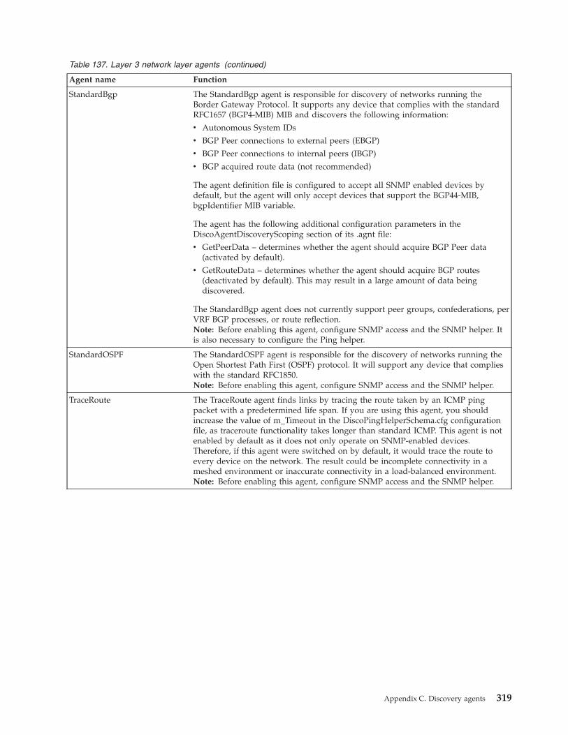
Table 137. Layer 3 network layer agents (continued)
Agent name Function
StandardBgp The StandardBgp agent is responsible for discovery of networks running theBorder Gateway Protocol. It supports any device that complies with the standardRFC1657 (BGP4-MIB) MIB and discovers the following information:
v Autonomous System IDs
v BGP Peer connections to external peers (EBGP)
v BGP Peer connections to internal peers (IBGP)
v BGP acquired route data (not recommended)
The agent definition file is configured to accept all SNMP enabled devices bydefault, but the agent will only accept devices that support the BGP44-MIB,bgpIdentifier MIB variable.
The agent has the following additional configuration parameters in theDiscoAgentDiscoveryScoping section of its .agnt file:
v GetPeerData – determines whether the agent should acquire BGP Peer data(activated by default).
v GetRouteData – determines whether the agent should acquire BGP routes(deactivated by default). This may result in a large amount of data beingdiscovered.
The StandardBgp agent does not currently support peer groups, confederations, perVRF BGP processes, or route reflection.Note: Before enabling this agent, configure SNMP access and the SNMP helper. Itis also necessary to configure the Ping helper.
StandardOSPF The StandardOSPF agent is responsible for the discovery of networks running theOpen Shortest Path First (OSPF) protocol. It will support any device that complieswith the standard RFC1850.Note: Before enabling this agent, configure SNMP access and the SNMP helper.
TraceRoute The TraceRoute agent finds links by tracing the route taken by an ICMP pingpacket with a predetermined life span. If you are using this agent, you shouldincrease the value of m_Timeout in the DiscoPingHelperSchema.cfg configurationfile, as traceroute functionality takes longer than standard ICMP. This agent is notenabled by default as it does not only operate on SNMP-enabled devices.Therefore, if this agent were switched on by default, it would trace the route toevery device on the network. The result could be incomplete connectivity in ameshed environment or inaccurate connectivity in a load-balanced environment.Note: Before enabling this agent, configure SNMP access and the SNMP helper.
Appendix C. Discovery agents 319
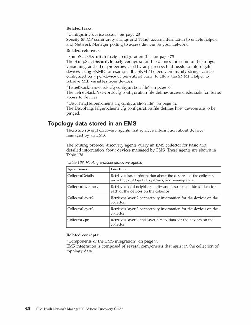
Related tasks:“Configuring device access” on page 23Specify SNMP community strings and Telnet access information to enable helpersand Network Manager polling to access devices on your network.Related reference:“SnmpStackSecurityInfo.cfg configuration file” on page 75The SnmpStackSecurityInfo.cfg configuration file defines the community strings,versioning, and other properties used by any process that needs to interrogatedevices using SNMP, for example, the SNMP helper. Community strings can beconfigured on a per-device or per-subnet basis, to allow the SNMP Helper toretrieve MIB variables from devices.“TelnetStackPasswords.cfg configuration file” on page 78The TelnetStackPasswords.cfg configuration file defines access credentials for Telnetaccess to devices.“DiscoPingHelperSchema.cfg configuration file” on page 62The DiscoPingHelperSchema.cfg configuration file defines how devices are to bepinged.
Topology data stored in an EMSThere are several discovery agents that retrieve information about devicesmanaged by an EMS.
The routing protocol discovery agents query an EMS collector for basic anddetailed information about devices managed by EMS. These agents are shown inTable 138.
Table 138. Routing protocol discovery agents
Agent name Function
CollectorDetails Retrieves basic information about the devices on the collector,including sysObjectId, sysDescr, and naming data.
CollectorInventory Retrieves local neighbor, entity and associated address data foreach of the devices on the collector
CollectorLayer2 Retrieves layer 2 connectivity information for the devices on thecollector.
CollectorLayer3 Retrieves layer 3 connectivity information for the devices on thecollector.
CollectorVpn Retrieves layer 2 and layer 3 VPN data for the devices on thecollector.
Related concepts:“Components of the EMS integration” on page 90EMS integration is composed of several components that assist in the collection oftopology data.
320 IBM Tivoli Network Manager IP Edition: Discovery Guide
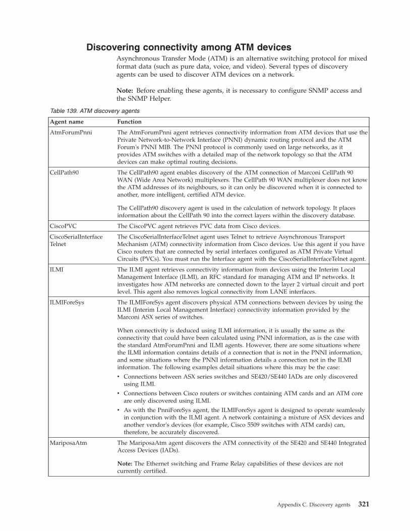
Discovering connectivity among ATM devicesAsynchronous Transfer Mode (ATM) is an alternative switching protocol for mixedformat data (such as pure data, voice, and video). Several types of discoveryagents can be used to discover ATM devices on a network.
Note: Before enabling these agents, it is necessary to configure SNMP access andthe SNMP Helper.
Table 139. ATM discovery agents
Agent name Function
AtmForumPnni The AtmForumPnni agent retrieves connectivity information from ATM devices that use thePrivate Network-to-Network Interface (PNNI) dynamic routing protocol and the ATMForum's PNNI MIB. The PNNI protocol is commonly used on large networks, as itprovides ATM switches with a detailed map of the network topology so that the ATMdevices can make optimal routing decisions.
CellPath90 The CellPath90 agent enables discovery of the ATM connection of Marconi CellPath 90WAN (Wide Area Network) multiplexers. The CellPath 90 WAN multiplexer does not knowthe ATM addresses of its neighbours, so it can only be discovered when it is connected toanother, more intelligent, certified ATM device.
The CellPath90 discovery agent is used in the calculation of network topology. It placesinformation about the CellPath 90 into the correct layers within the discovery database.
CiscoPVC The CiscoPVC agent retrieves PVC data from Cisco devices.
CiscoSerialInterfaceTelnet
The CiscoSerialInterfaceTelnet agent uses Telnet to retrieve Asynchronous TransportMechanism (ATM) connectivity information from Cisco devices. Use this agent if you haveCisco routers that are connected by serial interfaces configured as ATM Private VirtualCircuits (PVCs). You must run the Interface agent with the CiscoSerialInterfaceTelnet agent.
ILMI The ILMI agent retrieves connectivity information from devices using the Interim LocalManagement Interface (ILMI), an RFC standard for managing ATM and IP networks. Itinvestigates how ATM networks are connected down to the layer 2 virtual circuit and portlevel. This agent also removes logical connectivity from LANE interfaces.
ILMIForeSys The ILMIForeSys agent discovers physical ATM connections between devices by using theILMI (Interim Local Management Interface) connectivity information provided by theMarconi ASX series of switches.
When connectivity is deduced using ILMI information, it is usually the same as theconnectivity that could have been calculated using PNNI information, as is the case withthe standard AtmForumPnni and ILMI agents. However, there are some situations wherethe ILMI information contains details of a connection that is not in the PNNI information,and some situations where the PNNI information details a connection not in the ILMIinformation. The following examples detail situations where this may be the case:
v Connections between ASX series switches and SE420/SE440 IADs are only discoveredusing ILMI.
v Connections between Cisco routers or switches containing ATM cards and an ATM coreare only discovered using ILMI.
v As with the PnniForeSys agent, the ILMIForeSys agent is designed to operate seamlesslyin conjunction with the ILMI agent. A network containing a mixture of ASX devices andanother vendor's devices (for example, Cisco 5509 switches with ATM cards) can,therefore, be accurately discovered.
MariposaAtm The MariposaAtm agent discovers the ATM connectivity of the SE420 and SE440 IntegratedAccess Devices (IADs).
Note: The Ethernet switching and Frame Relay capabilities of these devices are notcurrently certified.
Appendix C. Discovery agents 321
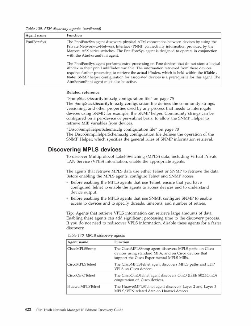
Table 139. ATM discovery agents (continued)
Agent name Function
PnniForeSys The PnniForeSys agent discovers physical ATM connections between devices by using thePrivate Network-to-Network Interface (PNNI) connectivity information provided by theMarconi ASX series switches. The PnniForeSys agent is designed to operate in conjunctionwith the AtmForumPnni agent.
The PnniForeSys agent performs extra processing on Fore devices that do not store a logicalifIndex in their pnniLinkIfIndex variable. The information retrieved from these devicesrequires further processing to retrieve the actual ifIndex, which is held within the ifTable .Note: SNMP helper configuration for associated devices is a prerequisite for this agent. TheAtmForumPnni agent must also be active.
Related reference:“SnmpStackSecurityInfo.cfg configuration file” on page 75The SnmpStackSecurityInfo.cfg configuration file defines the community strings,versioning, and other properties used by any process that needs to interrogatedevices using SNMP, for example, the SNMP helper. Community strings can beconfigured on a per-device or per-subnet basis, to allow the SNMP Helper toretrieve MIB variables from devices.“DiscoSnmpHelperSchema.cfg configuration file” on page 70The DiscoSnmpHelperSchema.cfg configuration file defines the operation of theSNMP Helper, which specifies the general rules of SNMP information retrieval.
Discovering MPLS devicesTo discover Multiprotocol Label Switching (MPLS) data, including Virtual PrivateLAN Service (VPLS) information, enable the appropriate agents.
The agents that retrieve MPLS data use either Telnet or SNMP to retrieve the data.Before enabling the MPLS agents, configure Telnet and SNMP access.v Before enabling the MPLS agents that use Telnet, ensure that you have
configured Telnet to enable the agents to access devices and to understanddevice output.
v Before enabling the MPLS agents that use SNMP, configure SNMP to enableaccess to devices and to specify threads, timeouts, and number of retries.
Tip: Agents that retrieve VPLS information can retrieve large amounts of data.Enabling these agents can add significant processing time to the discovery process.If you do not need to rediscover VPLS information, disable these agents for a fasterdiscovery.
Table 140. MPLS discovery agents
Agent name Function
CiscoMPLSSnmp The CiscoMPLSSnmp agent discovers MPLS paths on Ciscodevices using standard MIBs, and on Cisco devices thatsupport the Cisco Experimental MPLS MIBs.
CiscoMPLSTelnet The CiscoMPLSTelnet agent discovers MPLS paths and LDPVPLS on Cisco devices.
CiscoQinQTelnet The CiscoQinQTelnet agent discovers QinQ (IEEE 802.1QinQ)conguration on Cisco devices.
HuaweiMPLSTelnet The HuaweiMPLSTelnet agent discovers Layer 2 and Layer 3MPLS/VPN related data on Huawei devices.
322 IBM Tivoli Network Manager IP Edition: Discovery Guide
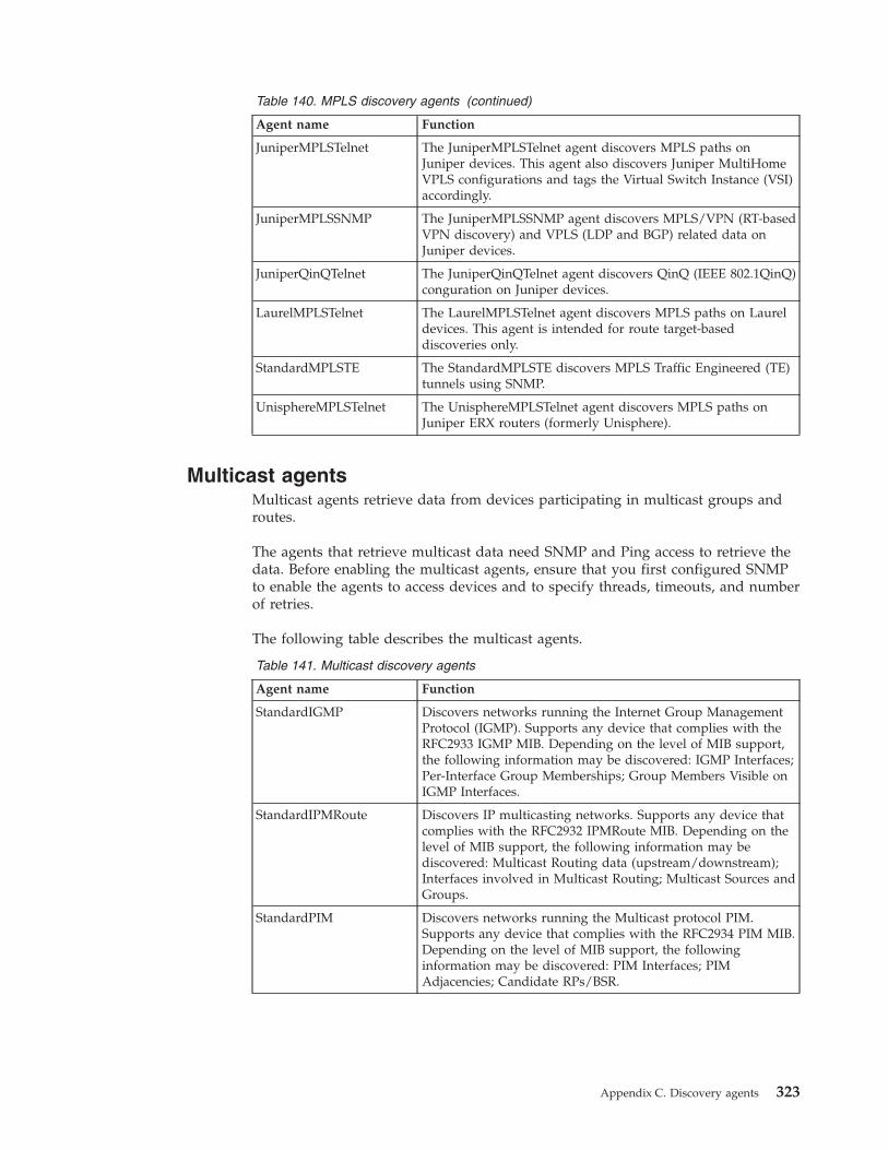
Table 140. MPLS discovery agents (continued)
Agent name Function
JuniperMPLSTelnet The JuniperMPLSTelnet agent discovers MPLS paths onJuniper devices. This agent also discovers Juniper MultiHomeVPLS configurations and tags the Virtual Switch Instance (VSI)accordingly.
JuniperMPLSSNMP The JuniperMPLSSNMP agent discovers MPLS/VPN (RT-basedVPN discovery) and VPLS (LDP and BGP) related data onJuniper devices.
JuniperQinQTelnet The JuniperQinQTelnet agent discovers QinQ (IEEE 802.1QinQ)conguration on Juniper devices.
LaurelMPLSTelnet The LaurelMPLSTelnet agent discovers MPLS paths on Laureldevices. This agent is intended for route target-baseddiscoveries only.
StandardMPLSTE The StandardMPLSTE discovers MPLS Traffic Engineered (TE)tunnels using SNMP.
UnisphereMPLSTelnet The UnisphereMPLSTelnet agent discovers MPLS paths onJuniper ERX routers (formerly Unisphere).
Multicast agentsMulticast agents retrieve data from devices participating in multicast groups androutes.
The agents that retrieve multicast data need SNMP and Ping access to retrieve thedata. Before enabling the multicast agents, ensure that you first configured SNMPto enable the agents to access devices and to specify threads, timeouts, and numberof retries.
The following table describes the multicast agents.
Table 141. Multicast discovery agents
Agent name Function
StandardIGMP Discovers networks running the Internet Group ManagementProtocol (IGMP). Supports any device that complies with theRFC2933 IGMP MIB. Depending on the level of MIB support,the following information may be discovered: IGMP Interfaces;Per-Interface Group Memberships; Group Members Visible onIGMP Interfaces.
StandardIPMRoute Discovers IP multicasting networks. Supports any device thatcomplies with the RFC2932 IPMRoute MIB. Depending on thelevel of MIB support, the following information may bediscovered: Multicast Routing data (upstream/downstream);Interfaces involved in Multicast Routing; Multicast Sources andGroups.
StandardPIM Discovers networks running the Multicast protocol PIM.Supports any device that complies with the RFC2934 PIM MIB.Depending on the level of MIB support, the followinginformation may be discovered: PIM Interfaces; PIMAdjacencies; Candidate RPs/BSR.
Appendix C. Discovery agents 323
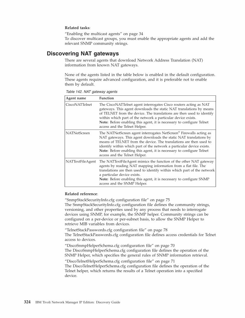
Related tasks:“Enabling the multicast agents” on page 34To discover multicast groups, you must enable the appropriate agents and add therelevant SNMP community strings.
Discovering NAT gatewaysThere are several agents that download Network Address Translation (NAT)information from known NAT gateways.
None of the agents listed in the table below is enabled in the default configuration.These agents require advanced configuration, and it is preferable not to enablethem by default.
Table 142. NAT gateway agents
Agent name Function
CiscoNATTelnet The CiscoNATTelnet agent interrogates Cisco routers acting as NATgateways. This agent downloads the static NAT translations by meansof TELNET from the device. The translations are then used to identifywithin which part of the network a particular device exists.Note: Before enabling this agent, it is necessary to configure Telnetaccess and the Telnet Helper.
NATNetScreen The NATNetScreen agent interrogates NetScreen® Firewalls acting asNAT gateways. This agent downloads the static NAT translations bymeans of TELNET from the device. The translations are then used toidentify within which part of the network a particular device exists.Note: Before enabling this agent, it is necessary to configure Telnetaccess and the Telnet Helper.
NATTextFileAgent The NATTextFileAgent mimics the function of the other NAT gatewayagents by reading NAT mapping information from a flat file. Thetranslations are then used to identify within which part of the networka particular device exists.Note: Before enabling this agent, it is necessary to configure SNMPaccess and the SNMP Helper.
Related reference:“SnmpStackSecurityInfo.cfg configuration file” on page 75The SnmpStackSecurityInfo.cfg configuration file defines the community strings,versioning, and other properties used by any process that needs to interrogatedevices using SNMP, for example, the SNMP helper. Community strings can beconfigured on a per-device or per-subnet basis, to allow the SNMP Helper toretrieve MIB variables from devices.“TelnetStackPasswords.cfg configuration file” on page 78The TelnetStackPasswords.cfg configuration file defines access credentials for Telnetaccess to devices.“DiscoSnmpHelperSchema.cfg configuration file” on page 70The DiscoSnmpHelperSchema.cfg configuration file defines the operation of theSNMP Helper, which specifies the general rules of SNMP information retrieval.“DiscoTelnetHelperSchema.cfg configuration file” on page 71The DiscoTelnetHelperSchema.cfg configuration file defines the operation of theTelnet helper, which returns the results of a Telnet operation into a specifieddevice.
324 IBM Tivoli Network Manager IP Edition: Discovery Guide
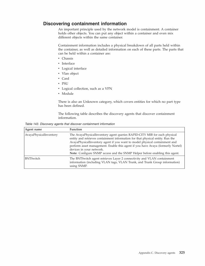
Discovering containment informationAn important principle used by the network model is containment. A containerholds other objects. You can put any object within a container and even mixdifferent objects within the same container.
Containment information includes a physical breakdown of all parts held withinthe container, as well as detailed information on each of these parts. The parts thatcan be held within a container are:v Chassisv Interfacev Logical interfacev Vlan objectv Cardv PSUv Logical collection, such as a VPNv Module
There is also an Unknown category, which covers entities for which no part typehas been defined.
The following table describes the discovery agents that discover containmentinformation.
Table 143. Discovery agents that discover containment information
Agent name Function
AvayaPhysicalInventory The AvayaPhysicalInventory agent queries RAPID-CITY MIB for each physicalentity and retrieves containment information for that physical entity. Run theAvayaPhysicalInventory agent if you want to model physical containment andperform asset management. Enable this agent if you have Avaya (formerly Nortel)devices in your network.Note: Configure SNMP access and the SNMP Helper before enabling this agent.
BNTSwitch The BNTSwitch agent retrieves Layer 2 connectivity and VLAN containmentinformation (including VLAN tags, VLAN Trunk, and Trunk Group information)using SNMP.
Appendix C. Discovery agents 325

Table 143. Discovery agents that discover containment information (continued)
Agent name Function
Entity The Entity agent queries the MIB for each entity and retrieves containmentinformation for that entity. Before enabling this agent, you must configure SNMPaccess and the SNMP Helper.
Running the Entity agent during a discovery is optional. Some containmentinformation is gathered during a discovery even if the Entity agent is not run. Runthe Entity agent to model physical containment and perform asset management.Note: During a discovery, the Entity agent retrieves a large amount of data. Thisslows down the discovery. You should therefore only use this agent if you need toperform asset management on the retrieved data.
You can configure the Entity agent to specify how much data the agent shouldretrieve. You can optionally choose to download this extra information from theentity MIBs of the , , Asset, ExtraPhysData, Module, Power, and Sensor entities. Dothis by setting the following variables in the Entity.agnt file:
v GetAssetData
v GetExtraPhysData
v GetModuleData
v GetPowerData
v GetSensorData
In each case, set a value of 1 to retrieve the data, and set a value of 0 if you do notwant to retrieve the data. The default value is 1.
In addition, you can specify how the Entity agent retrieves data from devices. Theoptions are as follows:
0 GetNextThis is the default value.
Using this data retrieval option, the system requests one SNMP variable ata time from the device in series, that is, retrieval of one column in a table,one value at a time for a given device. This approach is slower but putsleast pressure on the device. In a discovery with multiple entities theexpectation is that overall this approach will not slow down the discoveryas the SNMP helper is still busy with other activities. This approach mighttake a long time for individual large devices. This method works withSNMP version 1.
1 Asynchronous GetNextSimilar to the GetNext method in that one index is retrieved at a timewith the difference that all the columns are retrieved in parallel. This isalso supported by SNMP version 1 and is faster but it also puts slightlymore load on the device.
2 GetBulkRequests the entire column or multiple columns and individual Getcommands in one go. This method requires SNMP version 2 support. Ifthe device only supports version 1 then the retrieval method is brokendown into multiple SNMP Get Next and Get commands. This is the fastestretrieval and it does not put much more load on the device than theAsynchronous GetNext method. This method also involves larger packetson the network.
Note: The Entity.agnt file, together with all other agent configuration files, can befound in the $NCHOME/precision/disco/agents directory.
IfStackTable The IfStackTable determines the interface stacking hierarchy on devices thatsupport the RFC 2863 MIB.Note: Configure SNMP access and the SNMP Helper before enabling this agent.
326 IBM Tivoli Network Manager IP Edition: Discovery Guide
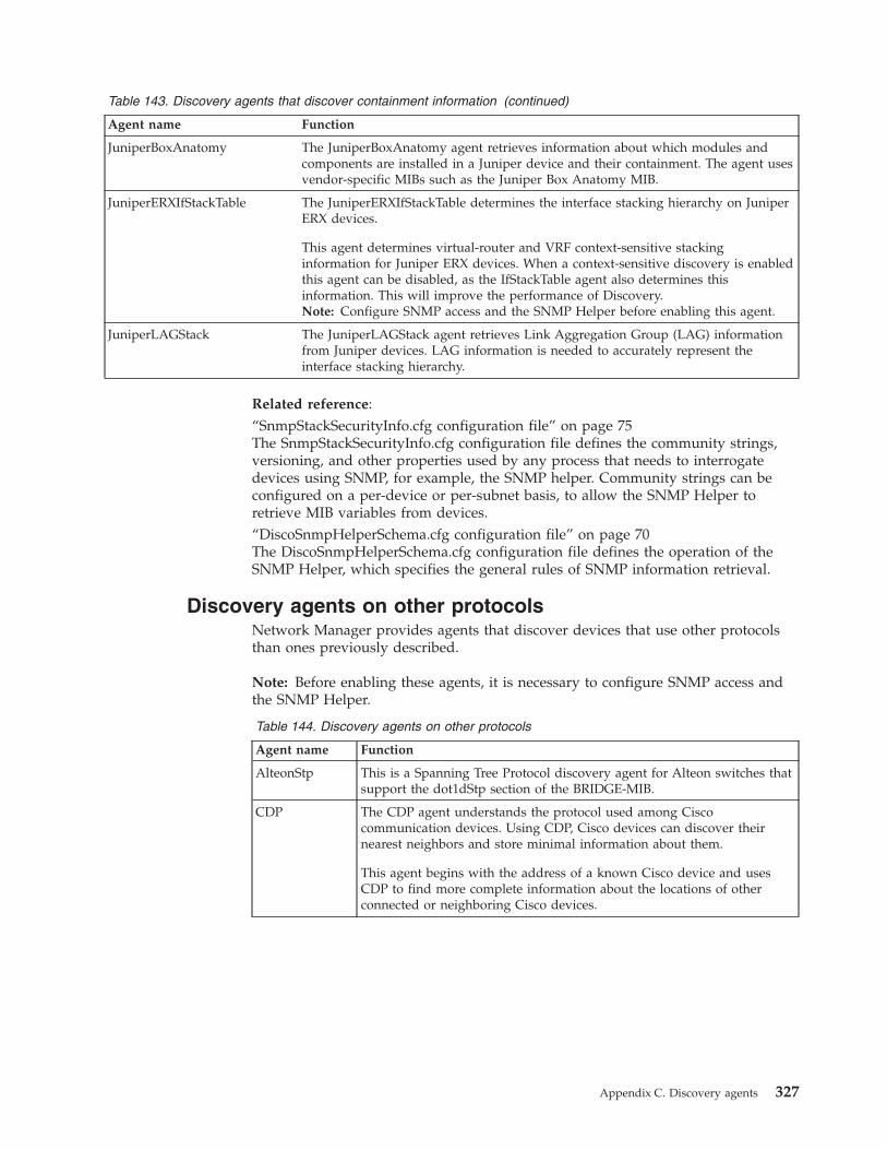
Table 143. Discovery agents that discover containment information (continued)
Agent name Function
JuniperBoxAnatomy The JuniperBoxAnatomy agent retrieves information about which modules andcomponents are installed in a Juniper device and their containment. The agent usesvendor-specific MIBs such as the Juniper Box Anatomy MIB.
JuniperERXIfStackTable The JuniperERXIfStackTable determines the interface stacking hierarchy on JuniperERX devices.
This agent determines virtual-router and VRF context-sensitive stackinginformation for Juniper ERX devices. When a context-sensitive discovery is enabledthis agent can be disabled, as the IfStackTable agent also determines thisinformation. This will improve the performance of Discovery.Note: Configure SNMP access and the SNMP Helper before enabling this agent.
JuniperLAGStack The JuniperLAGStack agent retrieves Link Aggregation Group (LAG) informationfrom Juniper devices. LAG information is needed to accurately represent theinterface stacking hierarchy.
Related reference:“SnmpStackSecurityInfo.cfg configuration file” on page 75The SnmpStackSecurityInfo.cfg configuration file defines the community strings,versioning, and other properties used by any process that needs to interrogatedevices using SNMP, for example, the SNMP helper. Community strings can beconfigured on a per-device or per-subnet basis, to allow the SNMP Helper toretrieve MIB variables from devices.“DiscoSnmpHelperSchema.cfg configuration file” on page 70The DiscoSnmpHelperSchema.cfg configuration file defines the operation of theSNMP Helper, which specifies the general rules of SNMP information retrieval.
Discovery agents on other protocolsNetwork Manager provides agents that discover devices that use other protocolsthan ones previously described.
Note: Before enabling these agents, it is necessary to configure SNMP access andthe SNMP Helper.
Table 144. Discovery agents on other protocols
Agent name Function
AlteonStp This is a Spanning Tree Protocol discovery agent for Alteon switches thatsupport the dot1dStp section of the BRIDGE-MIB.
CDP The CDP agent understands the protocol used among Ciscocommunication devices. Using CDP, Cisco devices can discover theirnearest neighbors and store minimal information about them.
This agent begins with the address of a known Cisco device and usesCDP to find more complete information about the locations of otherconnected or neighboring Cisco devices.
Appendix C. Discovery agents 327
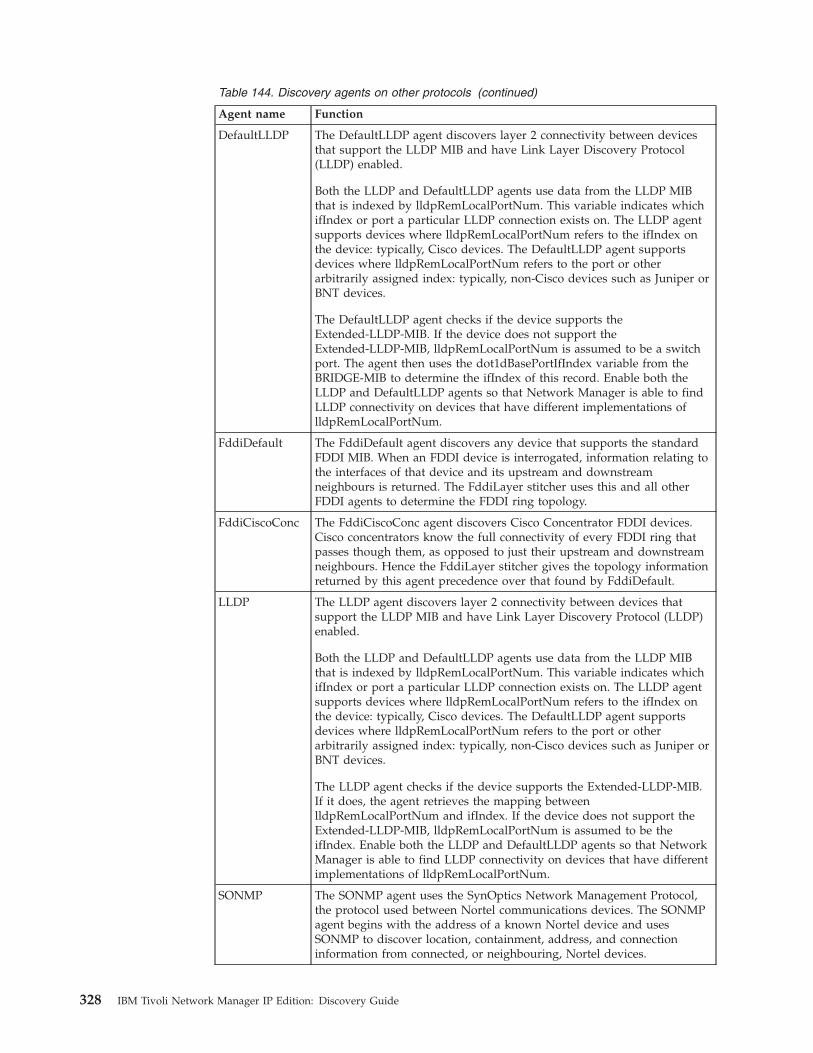
Table 144. Discovery agents on other protocols (continued)
Agent name Function
DefaultLLDP The DefaultLLDP agent discovers layer 2 connectivity between devicesthat support the LLDP MIB and have Link Layer Discovery Protocol(LLDP) enabled.
Both the LLDP and DefaultLLDP agents use data from the LLDP MIBthat is indexed by lldpRemLocalPortNum. This variable indicates whichifIndex or port a particular LLDP connection exists on. The LLDP agentsupports devices where lldpRemLocalPortNum refers to the ifIndex onthe device: typically, Cisco devices. The DefaultLLDP agent supportsdevices where lldpRemLocalPortNum refers to the port or otherarbitrarily assigned index: typically, non-Cisco devices such as Juniper orBNT devices.
The DefaultLLDP agent checks if the device supports theExtended-LLDP-MIB. If the device does not support theExtended-LLDP-MIB, lldpRemLocalPortNum is assumed to be a switchport. The agent then uses the dot1dBasePortIfIndex variable from theBRIDGE-MIB to determine the ifIndex of this record. Enable both theLLDP and DefaultLLDP agents so that Network Manager is able to findLLDP connectivity on devices that have different implementations oflldpRemLocalPortNum.
FddiDefault The FddiDefault agent discovers any device that supports the standardFDDI MIB. When an FDDI device is interrogated, information relating tothe interfaces of that device and its upstream and downstreamneighbours is returned. The FddiLayer stitcher uses this and all otherFDDI agents to determine the FDDI ring topology.
FddiCiscoConc The FddiCiscoConc agent discovers Cisco Concentrator FDDI devices.Cisco concentrators know the full connectivity of every FDDI ring thatpasses though them, as opposed to just their upstream and downstreamneighbours. Hence the FddiLayer stitcher gives the topology informationreturned by this agent precedence over that found by FddiDefault.
LLDP The LLDP agent discovers layer 2 connectivity between devices thatsupport the LLDP MIB and have Link Layer Discovery Protocol (LLDP)enabled.
Both the LLDP and DefaultLLDP agents use data from the LLDP MIBthat is indexed by lldpRemLocalPortNum. This variable indicates whichifIndex or port a particular LLDP connection exists on. The LLDP agentsupports devices where lldpRemLocalPortNum refers to the ifIndex onthe device: typically, Cisco devices. The DefaultLLDP agent supportsdevices where lldpRemLocalPortNum refers to the port or otherarbitrarily assigned index: typically, non-Cisco devices such as Juniper orBNT devices.
The LLDP agent checks if the device supports the Extended-LLDP-MIB.If it does, the agent retrieves the mapping betweenlldpRemLocalPortNum and ifIndex. If the device does not support theExtended-LLDP-MIB, lldpRemLocalPortNum is assumed to be theifIndex. Enable both the LLDP and DefaultLLDP agents so that NetworkManager is able to find LLDP connectivity on devices that have differentimplementations of lldpRemLocalPortNum.
SONMP The SONMP agent uses the SynOptics Network Management Protocol,the protocol used between Nortel communications devices. The SONMPagent begins with the address of a known Nortel device and usesSONMP to discover location, containment, address, and connectioninformation from connected, or neighbouring, Nortel devices.
328 IBM Tivoli Network Manager IP Edition: Discovery Guide
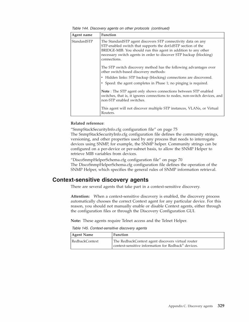
Table 144. Discovery agents on other protocols (continued)
Agent name Function
StandardSTP The StandardSTP agent discovers STP connectivity data on anySTP-enabled switch that supports the dot1dSTP section of theBRIDGE-MIB. You should run this agent in addition to any othernecessary switch agents in order to discover STP backup (blocking)connections.
The STP switch discovery method has the following advantages overother switch-based discovery methods:
v Hidden links: STP backup (blocking) connections are discovered.
v Speed: the agent completes in Phase 1; no pinging is required.
Note : The STP agent only shows connections between STP enabledswitches, that is, it ignores connections to nodes, non-switch devices, andnon-STP enabled switches.
This agent will not discover multiple STP instances, VLANs, or VirtualRouters.
Related reference:“SnmpStackSecurityInfo.cfg configuration file” on page 75The SnmpStackSecurityInfo.cfg configuration file defines the community strings,versioning, and other properties used by any process that needs to interrogatedevices using SNMP, for example, the SNMP helper. Community strings can beconfigured on a per-device or per-subnet basis, to allow the SNMP Helper toretrieve MIB variables from devices.“DiscoSnmpHelperSchema.cfg configuration file” on page 70The DiscoSnmpHelperSchema.cfg configuration file defines the operation of theSNMP Helper, which specifies the general rules of SNMP information retrieval.
Context-sensitive discovery agentsThere are several agents that take part in a context-sensitive discovery.
Attention: When a context-sensitive discovery is enabled, the discovery processautomatically chooses the correct Context agent for any particular device. For thisreason, you should not manually enable or disable Context agents, either throughthe configuration files or through the Discovery Configuration GUI.
Note: These agents require Telnet access and the Telnet Helper.
Table 145. Context-sensitive discovery agents
Agent Name Function
RedbackContext The RedbackContext agent discovers virtual routercontext-sensitive information for Redback® devices.
Appendix C. Discovery agents 329
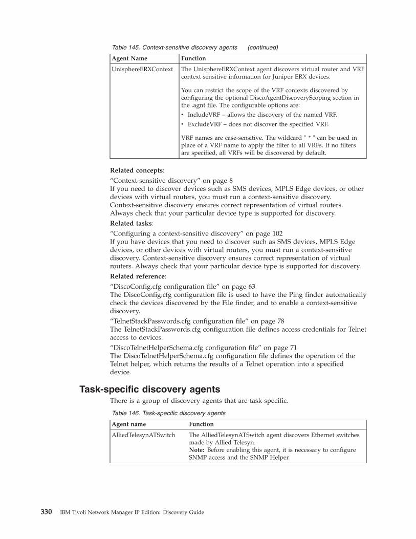
Table 145. Context-sensitive discovery agents (continued)
Agent Name Function
UnisphereERXContext The UnisphereERXContext agent discovers virtual router and VRFcontext-sensitive information for Juniper ERX devices.
You can restrict the scope of the VRF contexts discovered byconfiguring the optional DiscoAgentDiscoveryScoping section inthe .agnt file. The configurable options are:
v IncludeVRF – allows the discovery of the named VRF.
v ExcludeVRF – does not discover the specified VRF.
VRF names are case-sensitive. The wildcard " * " can be used inplace of a VRF name to apply the filter to all VRFs. If no filtersare specified, all VRFs will be discovered by default.
Related concepts:“Context-sensitive discovery” on page 8If you need to discover devices such as SMS devices, MPLS Edge devices, or otherdevices with virtual routers, you must run a context-sensitive discovery.Context-sensitive discovery ensures correct representation of virtual routers.Always check that your particular device type is supported for discovery.Related tasks:“Configuring a context-sensitive discovery” on page 102If you have devices that you need to discover such as SMS devices, MPLS Edgedevices, or other devices with virtual routers, you must run a context-sensitivediscovery. Context-sensitive discovery ensures correct representation of virtualrouters. Always check that your particular device type is supported for discovery.Related reference:“DiscoConfig.cfg configuration file” on page 63The DiscoConfig.cfg configuration file is used to have the Ping finder automaticallycheck the devices discovered by the File finder, and to enable a context-sensitivediscovery.“TelnetStackPasswords.cfg configuration file” on page 78The TelnetStackPasswords.cfg configuration file defines access credentials for Telnetaccess to devices.“DiscoTelnetHelperSchema.cfg configuration file” on page 71The DiscoTelnetHelperSchema.cfg configuration file defines the operation of theTelnet helper, which returns the results of a Telnet operation into a specifieddevice.
Task-specific discovery agentsThere is a group of discovery agents that are task-specific.
Table 146. Task-specific discovery agents
Agent name Function
AlliedTelesynATSwitch The AlliedTelesynATSwitch agent discovers Ethernet switchesmade by Allied Telesyn.Note: Before enabling this agent, it is necessary to configureSNMP access and the SNMP Helper.
330 IBM Tivoli Network Manager IP Edition: Discovery Guide
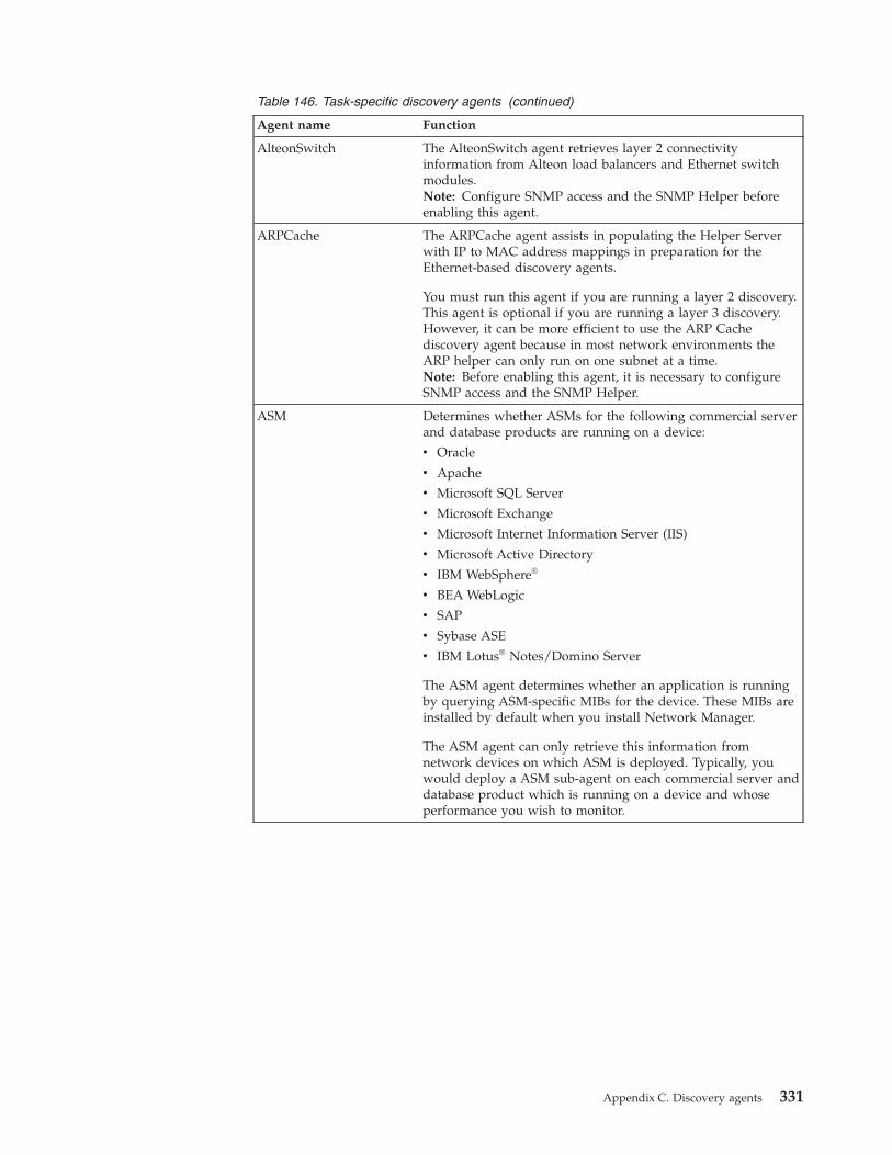
Table 146. Task-specific discovery agents (continued)
Agent name Function
AlteonSwitch The AlteonSwitch agent retrieves layer 2 connectivityinformation from Alteon load balancers and Ethernet switchmodules.Note: Configure SNMP access and the SNMP Helper beforeenabling this agent.
ARPCache The ARPCache agent assists in populating the Helper Serverwith IP to MAC address mappings in preparation for theEthernet-based discovery agents.
You must run this agent if you are running a layer 2 discovery.This agent is optional if you are running a layer 3 discovery.However, it can be more efficient to use the ARP Cachediscovery agent because in most network environments theARP helper can only run on one subnet at a time.Note: Before enabling this agent, it is necessary to configureSNMP access and the SNMP Helper.
ASM Determines whether ASMs for the following commercial serverand database products are running on a device:
v Oracle
v Apache
v Microsoft SQL Server
v Microsoft Exchange
v Microsoft Internet Information Server (IIS)
v Microsoft Active Directory
v IBM WebSphere®
v BEA WebLogic
v SAP
v Sybase ASE
v IBM Lotus® Notes/Domino Server
The ASM agent determines whether an application is runningby querying ASM-specific MIBs for the device. These MIBs areinstalled by default when you install Network Manager.
The ASM agent can only retrieve this information fromnetwork devices on which ASM is deployed. Typically, youwould deploy a ASM sub-agent on each commercial server anddatabase product which is running on a device and whoseperformance you wish to monitor.
Appendix C. Discovery agents 331
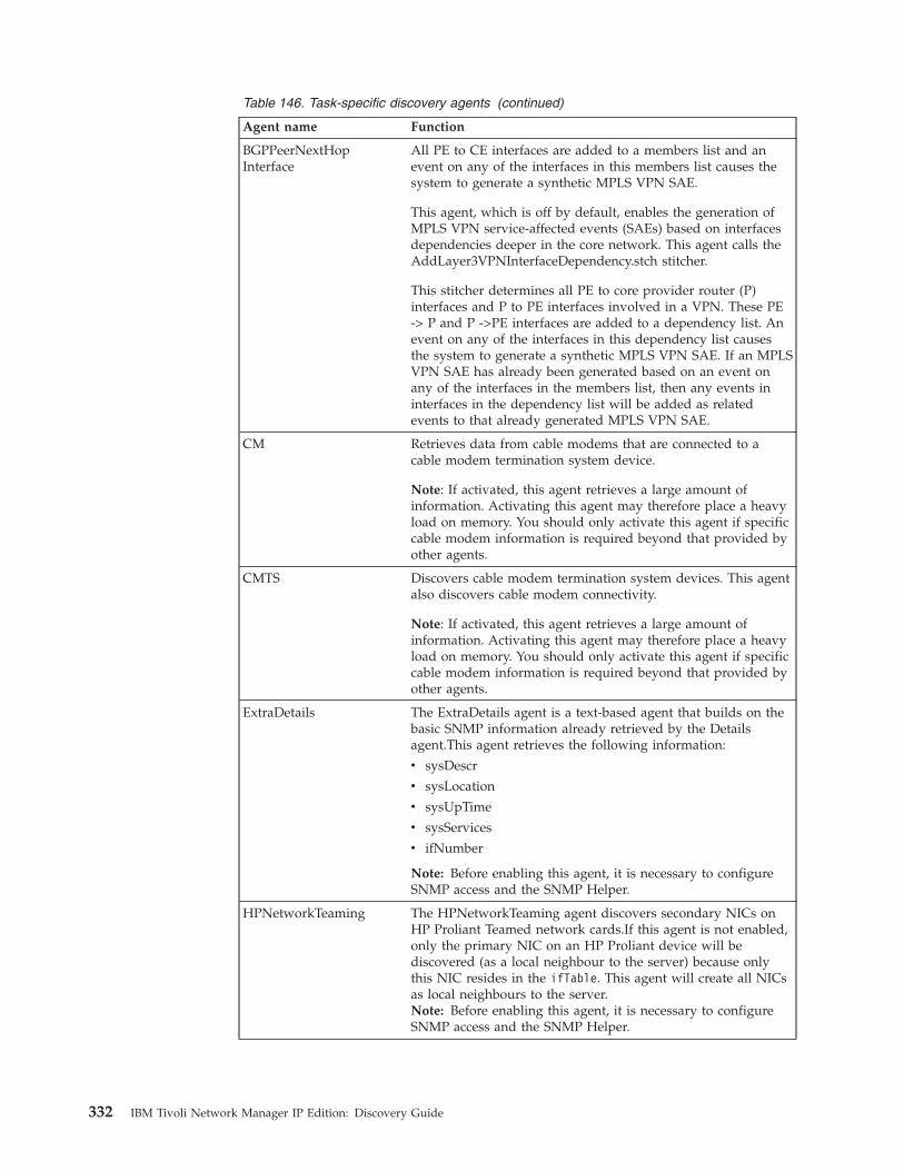
Table 146. Task-specific discovery agents (continued)
Agent name Function
BGPPeerNextHopInterface
All PE to CE interfaces are added to a members list and anevent on any of the interfaces in this members list causes thesystem to generate a synthetic MPLS VPN SAE.
This agent, which is off by default, enables the generation ofMPLS VPN service-affected events (SAEs) based on interfacesdependencies deeper in the core network. This agent calls theAddLayer3VPNInterfaceDependency.stch stitcher.
This stitcher determines all PE to core provider router (P)interfaces and P to PE interfaces involved in a VPN. These PE-> P and P ->PE interfaces are added to a dependency list. Anevent on any of the interfaces in this dependency list causesthe system to generate a synthetic MPLS VPN SAE. If an MPLSVPN SAE has already been generated based on an event onany of the interfaces in the members list, then any events ininterfaces in the dependency list will be added as relatedevents to that already generated MPLS VPN SAE.
CM Retrieves data from cable modems that are connected to acable modem termination system device.
Note: If activated, this agent retrieves a large amount ofinformation. Activating this agent may therefore place a heavyload on memory. You should only activate this agent if specificcable modem information is required beyond that provided byother agents.
CMTS Discovers cable modem termination system devices. This agentalso discovers cable modem connectivity.
Note: If activated, this agent retrieves a large amount ofinformation. Activating this agent may therefore place a heavyload on memory. You should only activate this agent if specificcable modem information is required beyond that provided byother agents.
ExtraDetails The ExtraDetails agent is a text-based agent that builds on thebasic SNMP information already retrieved by the Detailsagent.This agent retrieves the following information:
v sysDescr
v sysLocation
v sysUpTime
v sysServices
v ifNumber
Note: Before enabling this agent, it is necessary to configureSNMP access and the SNMP Helper.
HPNetworkTeaming The HPNetworkTeaming agent discovers secondary NICs onHP Proliant Teamed network cards.If this agent is not enabled,only the primary NIC on an HP Proliant device will bediscovered (as a local neighbour to the server) because onlythis NIC resides in the ifTable. This agent will create all NICsas local neighbours to the server.Note: Before enabling this agent, it is necessary to configureSNMP access and the SNMP Helper.
332 IBM Tivoli Network Manager IP Edition: Discovery Guide
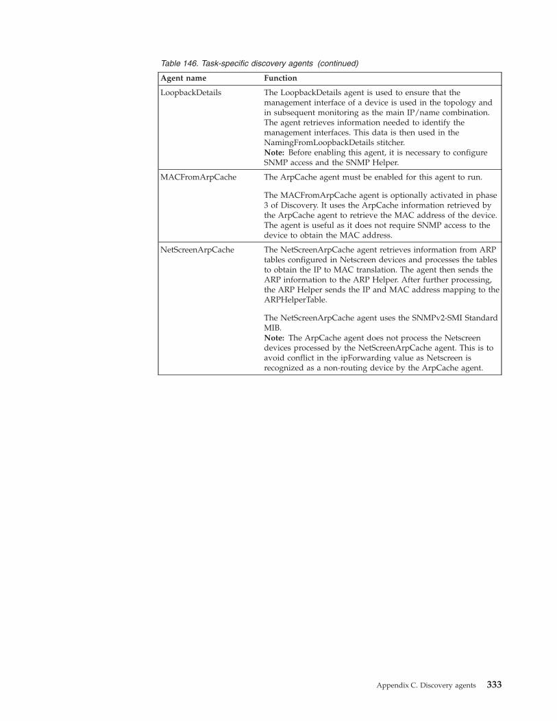
Table 146. Task-specific discovery agents (continued)
Agent name Function
LoopbackDetails The LoopbackDetails agent is used to ensure that themanagement interface of a device is used in the topology andin subsequent monitoring as the main IP/name combination.The agent retrieves information needed to identify themanagement interfaces. This data is then used in theNamingFromLoopbackDetails stitcher.Note: Before enabling this agent, it is necessary to configureSNMP access and the SNMP Helper.
MACFromArpCache The ArpCache agent must be enabled for this agent to run.
The MACFromArpCache agent is optionally activated in phase3 of Discovery. It uses the ArpCache information retrieved bythe ArpCache agent to retrieve the MAC address of the device.The agent is useful as it does not require SNMP access to thedevice to obtain the MAC address.
NetScreenArpCache The NetScreenArpCache agent retrieves information from ARPtables configured in Netscreen devices and processes the tablesto obtain the IP to MAC translation. The agent then sends theARP information to the ARP Helper. After further processing,the ARP Helper sends the IP and MAC address mapping to theARPHelperTable.
The NetScreenArpCache agent uses the SNMPv2-SMI StandardMIB.Note: The ArpCache agent does not process the Netscreendevices processed by the NetScreenArpCache agent. This is toavoid conflict in the ipForwarding value as Netscreen isrecognized as a non-routing device by the ArpCache agent.
Appendix C. Discovery agents 333
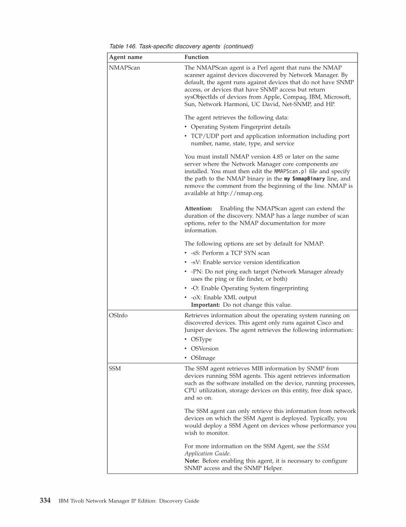
Table 146. Task-specific discovery agents (continued)
Agent name Function
NMAPScan The NMAPScan agent is a Perl agent that runs the NMAPscanner against devices discovered by Network Manager. Bydefault, the agent runs against devices that do not have SNMPaccess, or devices that have SNMP access but returnsysObjectIds of devices from Apple, Compaq, IBM, Microsoft,Sun, Network Harmoni, UC David, Net-SNMP, and HP.
The agent retrieves the following data:
v Operating System Fingerprint details
v TCP/UDP port and application information including portnumber, name, state, type, and service
You must install NMAP version 4.85 or later on the sameserver where the Network Manager core components areinstalled. You must then edit the NMAPScan.pl file and specifythe path to the NMAP binary in the my $nmapBinary line, andremove the comment from the beginning of the line. NMAP isavailable at http://nmap.org.
Attention: Enabling the NMAPScan agent can extend theduration of the discovery. NMAP has a large number of scanoptions, refer to the NMAP documentation for moreinformation.
The following options are set by default for NMAP:
v -sS: Perform a TCP SYN scan
v -sV: Enable service version identification
v -PN: Do not ping each target (Network Manager alreadyuses the ping or file finder, or both)
v -O: Enable Operating System fingerprinting
v -oX: Enable XML outputImportant: Do not change this value.
OSInfo Retrieves information about the operating system running ondiscovered devices. This agent only runs against Cisco andJuniper devices. The agent retrieves the following information:
v OSType
v OSVersion
v OSImage
SSM The SSM agent retrieves MIB information by SNMP fromdevices running SSM agents. This agent retrieves informationsuch as the software installed on the device, running processes,CPU utilization, storage devices on this entity, free disk space,and so on.
The SSM agent can only retrieve this information from networkdevices on which the SSM Agent is deployed. Typically, youwould deploy a SSM Agent on devices whose performance youwish to monitor.
For more information on the SSM Agent, see the SSMApplication Guide.Note: Before enabling this agent, it is necessary to configureSNMP access and the SNMP Helper.
334 IBM Tivoli Network Manager IP Edition: Discovery Guide
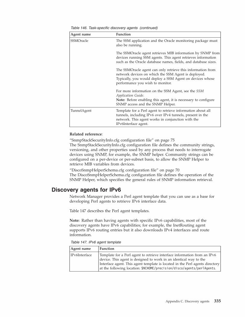
Table 146. Task-specific discovery agents (continued)
Agent name Function
SSMOracle The SSM application and the Oracle monitoring package mustalso be running.
The SSMOracle agent retrieves MIB information by SNMP fromdevices running SSM agents. This agent retrieves informationsuch as the Oracle database names, fields, and database sizes.
The SSMOracle agent can only retrieve this information fromnetwork devices on which the SSM Agent is deployed.Typically, you would deploy a SSM Agent on devices whoseperformance you wish to monitor.
For more information on the SSM Agent, see the SSMApplication Guide.Note: Before enabling this agent, it is necessary to configureSNMP access and the SNMP Helper.
TunnelAgent Template for a Perl agent to retrieve information about alltunnels, including IPv6 over IPv4 tunnels, present in thenetwork. This agent works in conjunction with theIPv6Interface agent.
Related reference:“SnmpStackSecurityInfo.cfg configuration file” on page 75The SnmpStackSecurityInfo.cfg configuration file defines the community strings,versioning, and other properties used by any process that needs to interrogatedevices using SNMP, for example, the SNMP helper. Community strings can beconfigured on a per-device or per-subnet basis, to allow the SNMP Helper toretrieve MIB variables from devices.“DiscoSnmpHelperSchema.cfg configuration file” on page 70The DiscoSnmpHelperSchema.cfg configuration file defines the operation of theSNMP Helper, which specifies the general rules of SNMP information retrieval.
Discovery agents for IPv6Network Manager provides a Perl agent template that you can use as a base fordeveloping Perl agents to retrieve IPv6 interface data.
Table 147 describes the Perl agent templates.
Note: Rather than having agents with specific IPv6 capabilities, most of thediscovery agents have IPv6 capabilities; for example, the InetRouting agentsupports IPv6 routing entries but it also downloads IPv4 interfaces and routeinformation.
Table 147. IPv6 agent template
Agent name Function
IPv6Interface Template for a Perl agent to retrieve interface information from an IPv6device. This agent is designed to work in an identical way to theInterface agent. This agent template is located in the Perl agents directoryat the following location: $NCHOME/precision/disco/agents/perlAgents.
Appendix C. Discovery agents 335
Guidance for selecting agentsTo discover device technologies (that is, those that use protocols other than IP) onyour network, you must ensure that the appropriate agents are active.
The following list provides the non-IP device protocols that are supported byNetwork Manager. You can select the appropriate agents for these protocols.v Frame Relayv Private Network-Network Interface (PNNI)v Cisco Discovery Protocol (CDP)v Link Layer Discovery Protocol (LLDP)v Hot Standby Routing Protocol (HSRP)v Fibre Distributed Data Interface (FDDI)v Asynchronous Transfer Mode (ATM)v Integrated Local Management Interface (ILMI)v Multiprotocol Label Switching (MPLS)
Which IP layer agents to useThe IP layer agents that you need to use depend on the devices on your network:v If you do not want to have your IP routing tables accessed, you must only use
the IpBackupRoutes agent.This agent is not used by default as it has the following drawbacks:– It retrieves data from a table that is not dynamic. If the router has not been
refreshed, then the data retrieved by this agent may be spurious.– The table is large and therefore takes a long time to download.
v If there are modern devices on the network, you must use the IpRoutingTableagent and the IpForwardingTable agent.These agents provide an accurate picture of IP layer connectivity and aretherefore used by default.
Which standard agents to useThe standard agents that you need to use depend on the information you requireand the devices on your network.v The TraceRoute agent can be used if there is a firewall on the network, because
SNMP calls cannot always be made through firewalls. If you use the TraceRouteagent, you must specify, as a discovery seed, the subnet node for the subnet onthe other side of the firewall.
v The ArpCache agent retrieves the physical address of a device, so is onlyrequired (in conjunction with the Switch agents) when performing layer 2discoveries.
v Frame Relay agents should be run in conjunction with the IP layer agents if youneed to add DLCI information to the interfaces of Frame Relay devices.
v Switch agents must be run for a layer 2 discovery.v The device-specific and protocol-specific agents are only required to discover the
devices or protocols to which they relate.
336 IBM Tivoli Network Manager IP Edition: Discovery Guide
Which specialized agents to runSeveral agents need to run only when you need to discover certain device types ornetwork technologies.
The specialized agents that you need to run depend on the devices and protocolsin your network:v The Extreme agent can be used to extract layer 2 connectivity information, EDP
neighbors, and VLAN details from Extreme switches.v The ExtremeESRP agent discovers Extreme Standby Routing Table information
from Extreme routing switches.v The PnniForeSys agent discovers physical ATM connections between devices by
using the PNNI (Private Network-to-Network Interface) connectivity informationprovided by the Marconi ASX series switches.
v The ILMIForeSys agent discovers physical ATM connections between devices byusing the ILMI (Interim Local Management Interface) connectivity informationprovided by the Marconi ASX series switches.
v The CellPath90 agent discovers the ATM connection of a CellPath 90 WAN(Wide Area Network) multiplexer.
v The Marconi3810 agent discovers the Ethernet connectivity of the ES-3810switches running operating system version 4.x.x.
v The MariposaAtm agent discovers the ATM connectivity of the SE420 and SE440IADs.
Note: The Ethernet switching and Frame Relay capabilities of these devices arenot currently certified.
v The ILMI agent discovers connectivity between ATM devices running ILMI thatsupport the ATM Forum's ATM MIB. The CiscoPVC agent retrieves PVC datafrom Cisco devices.
v The AtmForumPnni agent discovers connectivity between devices running ATMForum PNNI that correctly support the ATM Forum's PNNI MIB.
v For Cisco devices, run the CiscoMPLSSnmp agent if you have the MPLS MIBsenabled on a device, otherwise, use the CiscoMPLSTelnet agent.
v For Juniper devices, run the JuniperMPLSTelnet agent if you wish to discoverMPLS paths.
v For Juniper ERX devices (formerly Unisphere), the UnisphereMPLSTelnet agentmust be used to discover MPLS paths, as these devices are sufficiently differentto the Juniper "M" series routers that a different agent is required.
v The StandardMPLSTE agent discovers MPLS Traffic Engineered (TE) tunnels.v The StandardIGMP agent discovers networks running the Internet Group
Management Protocol (IGMP).v The StandardIPMRoute agent discovers IP multicasting networks.v The StandardPIM agent discovers Protocol Independent Multicast (PIM) groups.Related reference:“Types of agents” on page 311The agents supplied with Network Manager can be divided into categoriesaccording to the type of data they retrieve or the technology they discover.
Appendix C. Discovery agents 337
Suggested agents for a layer 3 discoveryThe recommended agents for a layer 3 discovery depends on your network.
When running a layer 3 discovery, the following agents should be run:v Details and AssocAddressv A combination of the following IP layer agents:
– IpRoutingTable– IpBackupRoutes– IpRoutingTable and IpForwardingTable
v HSRPv VRRPv TraceRoute (if firewalls are present)v IPv4/6 InetRouting. If you have IPv6 in your network, consider running this
agent to discover the connectivity, particularly the IPv6 connectivity.
Tip: Some routers support layer 2 technologies. For example, when an ATM cardis located in a router chassis, layer 3 discovery agents, such as the IpRoutingTableagent, only discover interfaces with an IP address. Therefore, to fully discover allthe interfaces on routers that support layer 2 technologies, you must run theappropriate agents.Related reference:“Suggested agents for a layer 2 discovery”The recommended agents for a layer 2 discovery depends on your network.
Suggested agents for a layer 2 discoveryThe recommended agents for a layer 2 discovery depends on your network.
When running a layer 2 discovery, the following agents must be run:v Details and AssocAddressv A combination of the following IP layer agents:
– IpRoutingTable– IpBackupRoutes– IpRoutingTable and IpForwardingTable
v Switchv FrameRelayv ArpCachev ATMv FDDIv HSRPv VRRPv MPLSRelated reference:“Suggested agents for a layer 3 discovery”The recommended agents for a layer 3 discovery depends on your network.
338 IBM Tivoli Network Manager IP Edition: Discovery Guide

Appendix D. Helper System
The helpers are specialized applications that retrieve information from the networkon demand.
Note: If the helpers and the Helper Server are running on a different host to theDISCO process, and these hosts are behind a firewall, then specializedconfiguration is required to ensure that the Helper System can communicate withDISCO. For more information, see the IBM Tivoli Network Manager IP EditionAdministration Guide.
HelpersHelpers retrieve information from devices and deposit the information in theHelper Server for retrieval by the agents.
By default, there are six helpers, which are described in Table 148.
Table 148. Helpers available with Network Manager.Note: $NCHOME is the environment variable that contains the path to the netcool directory.
Helper Executable Configuration file Description
ARP ncp_dh_arp $NCHOME/etc/precision/DiscoARPHelperSchema.cfg
Performs IPaddress to MACaddress resolution.
DNS ncp_dh_dns $NCHOME/etc/precision/DiscoDNSHelperSchema.cfg
Performs IPaddress to devicename resolution.
PING ncp_dh_ping $NCHOME/etc/precision/DiscoPingHelperSchema.cfg
Either pings eachdevice in a subnet,an individual IPaddress or abroadcast ormulticast address.The result of theping could be usedto populate theMIB of the device.
SNMP ncp_dh_snmp $NCHOME/etc/precision/DiscoSnmpHelperSchema.cfg
$NCHOME/etc/precision/SnmpStackSchema.cfg
$NCHOME/etc/precision/SnmpStackSecurityInfo.cfg
Returns results ofan SNMP requestsuch as Get,GetNext andGetBulk.
TELNET ncp_dh_telnet $NCHOME/etc/precision/DiscoTelnetHelperSchema.cfg
$NCHOME/etc/precision/TelnetStackPasswords.cfg
$NCHOME/etc/precision/TelnetStackSchema.cfg
Returns the resultsof an OS commandagainst a specificdevice using theTelnet or SSHprotocol.
© Copyright IBM Corp. 2006, 2013 339
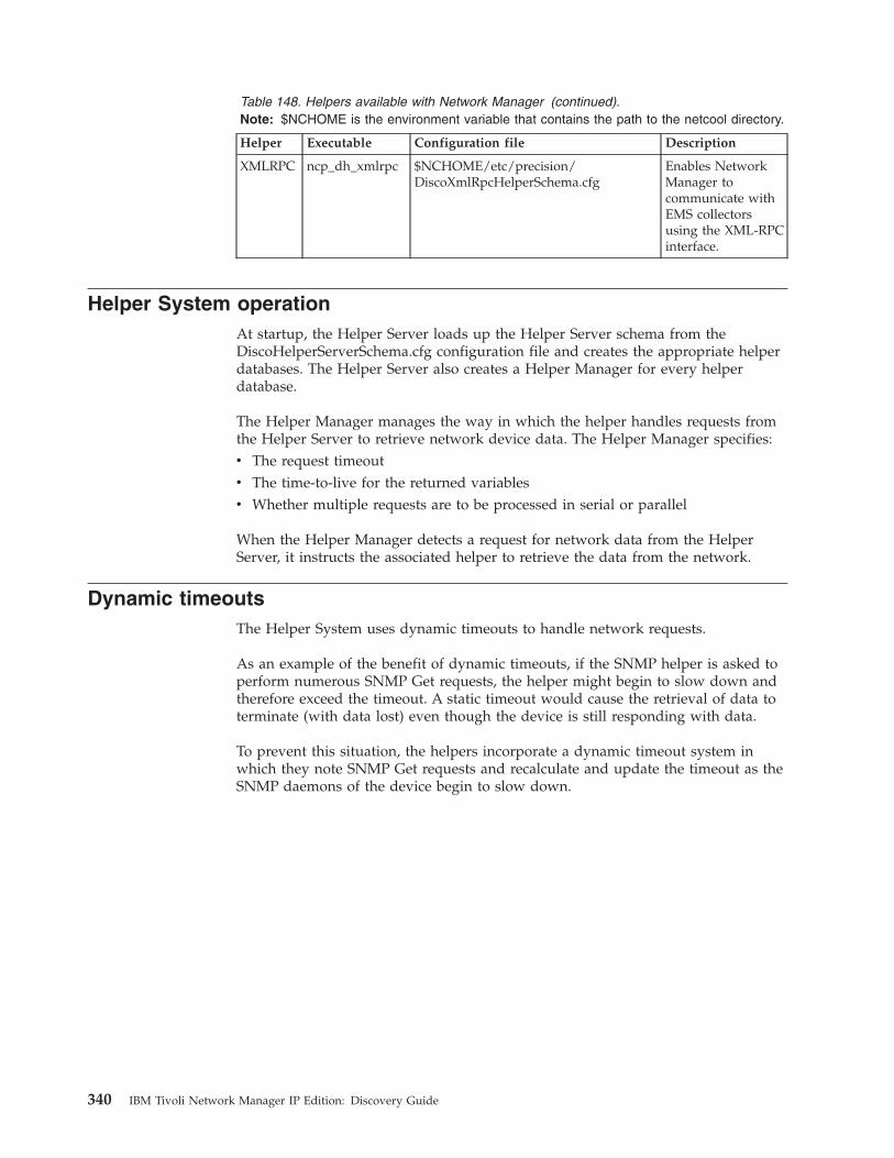
Table 148. Helpers available with Network Manager (continued).Note: $NCHOME is the environment variable that contains the path to the netcool directory.
Helper Executable Configuration file Description
XMLRPC ncp_dh_xmlrpc $NCHOME/etc/precision/DiscoXmlRpcHelperSchema.cfg
Enables NetworkManager tocommunicate withEMS collectorsusing the XML-RPCinterface.
Helper System operationAt startup, the Helper Server loads up the Helper Server schema from theDiscoHelperServerSchema.cfg configuration file and creates the appropriate helperdatabases. The Helper Server also creates a Helper Manager for every helperdatabase.
The Helper Manager manages the way in which the helper handles requests fromthe Helper Server to retrieve network device data. The Helper Manager specifies:v The request timeoutv The time-to-live for the returned variablesv Whether multiple requests are to be processed in serial or parallel
When the Helper Manager detects a request for network data from the HelperServer, it instructs the associated helper to retrieve the data from the network.
Dynamic timeoutsThe Helper System uses dynamic timeouts to handle network requests.
As an example of the benefit of dynamic timeouts, if the SNMP helper is asked toperform numerous SNMP Get requests, the helper might begin to slow down andtherefore exceed the timeout. A static timeout would cause the retrieval of data toterminate (with data lost) even though the device is still responding with data.
To prevent this situation, the helpers incorporate a dynamic timeout system inwhich they note SNMP Get requests and recalculate and update the timeout as theSNMP daemons of the device begin to slow down.
340 IBM Tivoli Network Manager IP Edition: Discovery Guide

Appendix E. Discovery stitchers
Stitchers are processes that transfer, manipulate, and distribute data betweendatabases. The discovery stitchers also process the information collected by theagents and using this information to create the network topology.
The discovery stitchers supplied with Network Manager are stored in thefollowing directories.v Text-based discovery stitchers (text files with a .stch extension):
$NCHOME/precision/disco/stitchers/
v Precompiled discovery stitchers : $NCHOME/precision/platform/platform/lib/,where platform is the operating system on which Network Manager is running;for example, linux2x86, win32, solaris2, aix5, hpux11, or linux2s390.
For information on stitcher language, see the IBM Tivoli Network Manager IP EditionLanguage Reference.
Main discovery stitchersThis topic lists all discovery stitchers.
The following table describes the discovery stitchers currently included withNetwork Manager.
Note: This list is subject to change.
Table 149. List of Network Manager discovery stitchers
Stitcher Function
AddAEPhysicalIFContainment Adds physical interfaces to the chassis in the Link AggregationGroup (LAG) containment structure of Juniper devices. This stitcheris called by BuildContainment.stch.
AddBaseNATTags Updates all the private NAT addresses that have a private addresswith their public address and adds a tag denoting the privateaddress.
AddBasicContainment Part of the mechanism for containment stitching. This stitcher insertscontainment information into the simple chassis.
AddCardContainment Adds card objects to the workingEntities.containment table.
AddContainedByAttribute Adds an ExtraInfo attribute called m_PhysicallyContainedBy. It isanalogous to the RFC2737 attribute entPhysicalContainedIn andidentifies the record that contains a particular record. This data isused by Netcool® for Asset Management and the Cramer integrationand must be uncommented in the PostScratchProcessing stitcherwhen using those applications.
AddEntityContainment Adds general entity information to the workingEntities.containmenttable.
AddGlobalVlans Builds global Virtual Local Area Network (VLAN) objects using thetranslations.vlans table.
AddIfStackContainment Adds interface stack objects to the workingEntities.containmenttable.
© Copyright IBM Corp. 2006, 2013 341
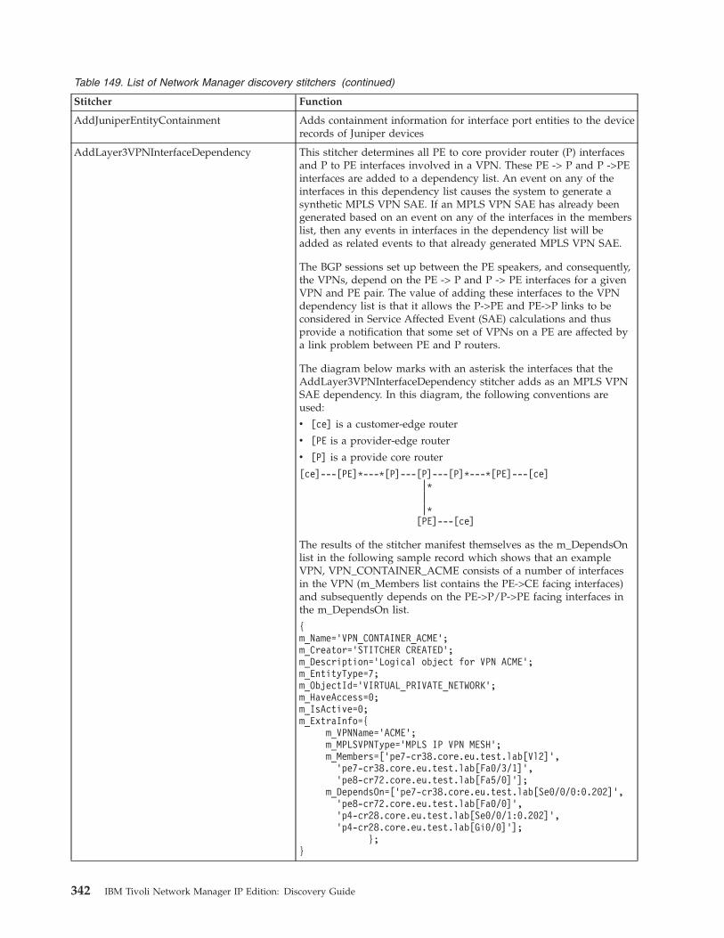
Table 149. List of Network Manager discovery stitchers (continued)
Stitcher Function
AddJuniperEntityContainment Adds containment information for interface port entities to the devicerecords of Juniper devices
AddLayer3VPNInterfaceDependency This stitcher determines all PE to core provider router (P) interfacesand P to PE interfaces involved in a VPN. These PE -> P and P ->PEinterfaces are added to a dependency list. An event on any of theinterfaces in this dependency list causes the system to generate asynthetic MPLS VPN SAE. If an MPLS VPN SAE has already beengenerated based on an event on any of the interfaces in the memberslist, then any events in interfaces in the dependency list will beadded as related events to that already generated MPLS VPN SAE.
The BGP sessions set up between the PE speakers, and consequently,the VPNs, depend on the PE -> P and P -> PE interfaces for a givenVPN and PE pair. The value of adding these interfaces to the VPNdependency list is that it allows the P->PE and PE->P links to beconsidered in Service Affected Event (SAE) calculations and thusprovide a notification that some set of VPNs on a PE are affected bya link problem between PE and P routers.
The diagram below marks with an asterisk the interfaces that theAddLayer3VPNInterfaceDependency stitcher adds as an MPLS VPNSAE dependency. In this diagram, the following conventions areused:
v [ce] is a customer-edge router
v [PE is a provider-edge router
v [P] is a provide core router
[ce]---[PE]*---*[P]---[P]---[P]*---*[PE]---[ce]|*||*
[PE]---[ce]
The results of the stitcher manifest themselves as the m_DependsOnlist in the following sample record which shows that an exampleVPN, VPN_CONTAINER_ACME consists of a number of interfacesin the VPN (m_Members list contains the PE->CE facing interfaces)and subsequently depends on the PE->P/P->PE facing interfaces inthe m_DependsOn list.
{m_Name=’VPN_CONTAINER_ACME’;m_Creator=’STITCHER CREATED’;m_Description=’Logical object for VPN ACME’;m_EntityType=7;m_ObjectId=’VIRTUAL_PRIVATE_NETWORK’;m_HaveAccess=0;m_IsActive=0;m_ExtraInfo={
m_VPNName=’ACME’;m_MPLSVPNType=’MPLS IP VPN MESH’;m_Members=[’pe7-cr38.core.eu.test.lab[Vl2]’,
’pe7-cr38.core.eu.test.lab[Fa0/3/1]’,’pe8-cr72.core.eu.test.lab[Fa5/0]’];
m_DependsOn=[’pe7-cr38.core.eu.test.lab[Se0/0/0:0.202]’,’pe8-cr72.core.eu.test.lab[Fa0/0]’,’p4-cr28.core.eu.test.lab[Se0/0/1:0.202]’,’p4-cr28.core.eu.test.lab[Gi0/0]’];
};}
342 IBM Tivoli Network Manager IP Edition: Discovery Guide

Table 149. List of Network Manager discovery stitchers (continued)
Stitcher Function
AddLogicalToIpToBaseName Adds logical information to the translations.ipToBaseName table.
AddLoopbackTag Adds a tag to the ExtraInfo column of the topology databaseindicating that an interface is a globally addressable loopbackinterface.
AddNoConnectionsToLayer The final topology layer is constructed by merging the topologyinformation from the various layers. If there is a mismatch inconnectivity information provided by the different layers, informationfrom the more detailed layer takes precedence.
For example, the Network Layer (layer 3) provides informationindicating that a router interface is connected to another routerinterface. However, information from the more detailed Data LinkLayer (layer 2) shows that there is actually a switch between the tworouter interfaces.
The AddNoConnectionsToLayer is used in cases where it is necessaryto remove a connection at one layer but keep the connection at adifferent layer.
AddOSPFAreaCollections Creates a logical collection for each OSPF area containing theinterfaces within that area.
AddSwitchRoutingLinks Adds switch routing data (that assists the RCA plug-in whenperforming Root Cause Analysis) to the topology database.
AddTechnologyType Optional stitcher called by the PostScratchProcessing.stch stitcher.This stitcher is commented out by default. If enabled, this stitchercreates a technology type variable for each interface object. Thisvariable can then be used to create technology-based Network Views.
See the IBM Tivoli Network Manager IP Edition Network VisualizationSetup Guide for more information about network views.
The stitcher creates the technology type variable by adding anm_Technology field to the ExtraInfo field within thescratchTopology.entityByName table for each interface object. Them_Technology field is a string, such as Ethernet, ATM. The stitchercontains a large collection of default technology types; more can beadded by directly altering the stitcher.
The small processing load associated with activating this stitchermight slow down your discovery slightly.
AddUnconnectedContainment Gives unconnected entities a default containment. Unconnectedentities do not have a parent, except for their main node or interface.
AddUnmanagedHub Infers the existence of an unmanaged hub if the discovery finds aport that is connected to more than one item. This stitcher thenconnects that port to an unmanaged hub, and also connects all theother ports involved in the connection to the unmanaged hub. Theseconnections make the topology clearer.
AddVlanContainers Uses information in the workingEntities.finalEntity andtranslations.vlans tables to add VLAN objects to theworkingEntities.containment table.
AddVTPCollections Augments the VTP domain entities with ports that are connected toVTP domains.
AddVTPEdges Augments the VTP domain entities with ports that are connected toVTP domains.
Appendix E. Discovery stitchers 343
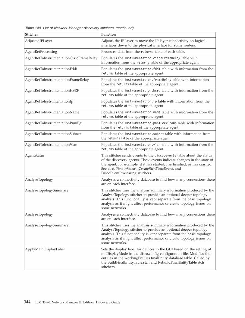
Table 149. List of Network Manager discovery stitchers (continued)
Stitcher Function
AdjustedIPLayer Adjusts the IP layer to move the IP layer connectivity on logicalinterfaces down to the physical interface for some routers.
AgentRetProcessing Processes data from the returns table of each table.
AgentRetToInstrumentationCiscoFrameRelay Populates the instrumentation.ciscoFrameRelay table withinformation from the returns table of the appropriate agent.
AgentRetToInstrumentationFddi Populates the instrumentation.fddi table with information from thereturns table of the appropriate agent.
AgentRetToInstrumentationFrameRelay Populates the instrumentation.frameRelay table with informationfrom the returns table of the appropriate agent.
AgentRetToInstrumentationHSRP Populates the instrumentation.hsrp table with information from thereturns table of the appropriate agent.
AgentRetToInstrumentationIp Populates the instrumentation.ip table with information from thereturns table of the appropriate agent.
AgentRetToInstrumentationName Populates the instrumentation.name table with information from thereturns table of the appropriate agent.
AgentRetToInstrumentationPnniPgi Populates the instrumentation.pnniPeerGroup table with informationfrom the returns table of the appropriate agent.
AgentRetToInstrumentationSubnet Populates the instrumentation.subNet table with information fromthe returns table of the appropriate agent.
AgentRetToInstrumentationVlan Populates the instrumentation.vlan table with information from thereturns table of the appropriate agent.
AgentStatus This stitcher sends events to the disco.events table about the statusof the discovery agents. These events indicate changes in the state ofthe agent; for example, if it has started, has finished, or has crashed.See also, FinderStatus, CreateStchTimeEvent, andDiscoEventProcessing stitchers.
AnalyseTopology Analyses a connectivity database to find how many connections thereare on each interface.
AnalyseTopologySummary This stitcher uses the analysis summary information produced by theAnalyseTopology stitcher to provide an optional deeper topologyanalysis. This functionality is kept separate from the basic topologyanalysis as it might affect performance or create topology issues onsome networks.
ApplyMainDisplayLabel Sets the display label for devices in the GUI based on the setting ofm_DisplayMode in the disco.config configuration file. Modifies theentities in the workingEntities.finalEntity database table. Called bythe BuildFinalEntityTable.stch and RebuildFinalEntityTable.stchstitchers.
344 IBM Tivoli Network Manager IP Edition: Discovery Guide
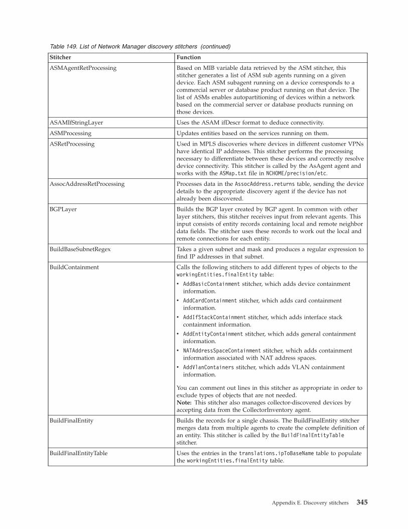
Table 149. List of Network Manager discovery stitchers (continued)
Stitcher Function
ASMAgentRetProcessing Based on MIB variable data retrieved by the ASM stitcher, thisstitcher generates a list of ASM sub agents running on a givendevice. Each ASM subagent running on a device corresponds to acommercial server or database product running on that device. Thelist of ASMs enables autopartitioning of devices within a networkbased on the commercial server or database products running onthose devices.
ASAMIfStringLayer Uses the ASAM ifDescr format to deduce connectivity.
ASMProcessing Updates entities based on the services running on them.
ASRetProcessing Used in MPLS discoveries where devices in different customer VPNshave identical IP addresses. This stitcher performs the processingnecessary to differentiate between these devices and correctly resolvedevice connectivity. This stitcher is called by the AsAgent agent andworks with the ASMap.txt file in NCHOME/precision/etc.
AssocAddressRetProcessing Processes data in the AssocAddress.returns table, sending the devicedetails to the appropriate discovery agent if the device has notalready been discovered.
BGPLayer Builds the BGP layer created by BGP agent. In common with otherlayer stitchers, this stitcher receives input from relevant agents. Thisinput consists of entity records containing local and remote neighbordata fields. The stitcher uses these records to work out the local andremote connections for each entity.
BuildBaseSubnetRegex Takes a given subnet and mask and produces a regular expression tofind IP addresses in that subnet.
BuildContainment Calls the following stitchers to add different types of objects to theworkingEntities.finalEntity table:
v AddBasicContainment stitcher, which adds device containmentinformation.
v AddCardContainment stitcher, which adds card containmentinformation.
v AddIfStackContainment stitcher, which adds interface stackcontainment information.
v AddEntityContainment stitcher, which adds general containmentinformation.
v NATAddressSpaceContainment stitcher, which adds containmentinformation associated with NAT address spaces.
v AddVlanContainers stitcher, which adds VLAN containmentinformation.
You can comment out lines in this stitcher as appropriate in order toexclude types of objects that are not needed.Note: This stitcher also manages collector-discovered devices byaccepting data from the CollectorInventory agent.
BuildFinalEntity Builds the records for a single chassis. The BuildFinalEntity stitchermerges data from multiple agents to create the complete definition ofan entity. This stitcher is called by the BuildFinalEntityTablestitcher.
BuildFinalEntityTable Uses the entries in the translations.ipToBaseName table to populatethe workingEntities.finalEntity table.
Appendix E. Discovery stitchers 345
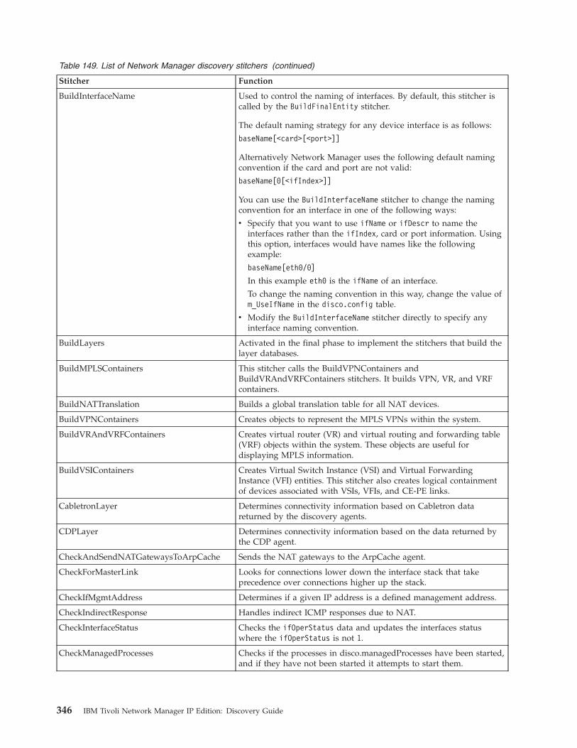
Table 149. List of Network Manager discovery stitchers (continued)
Stitcher Function
BuildInterfaceName Used to control the naming of interfaces. By default, this stitcher iscalled by the BuildFinalEntity stitcher.
The default naming strategy for any device interface is as follows:
baseName[<card>[<port>]]
Alternatively Network Manager uses the following default namingconvention if the card and port are not valid:
baseName[0[<ifIndex>]]
You can use the BuildInterfaceName stitcher to change the namingconvention for an interface in one of the following ways:
v Specify that you want to use ifName or ifDescr to name theinterfaces rather than the ifIndex, card or port information. Usingthis option, interfaces would have names like the followingexample:
baseName[eth0/0]
In this example eth0 is the ifName of an interface.
To change the naming convention in this way, change the value ofm_UseIfName in the disco.config table.
v Modify the BuildInterfaceName stitcher directly to specify anyinterface naming convention.
BuildLayers Activated in the final phase to implement the stitchers that build thelayer databases.
BuildMPLSContainers This stitcher calls the BuildVPNContainers andBuildVRAndVRFContainers stitchers. It builds VPN, VR, and VRFcontainers.
BuildNATTranslation Builds a global translation table for all NAT devices.
BuildVPNContainers Creates objects to represent the MPLS VPNs within the system.
BuildVRAndVRFContainers Creates virtual router (VR) and virtual routing and forwarding table(VRF) objects within the system. These objects are useful fordisplaying MPLS information.
BuildVSIContainers Creates Virtual Switch Instance (VSI) and Virtual ForwardingInstance (VFI) entities. This stitcher also creates logical containmentof devices associated with VSIs, VFIs, and CE-PE links.
CabletronLayer Determines connectivity information based on Cabletron datareturned by the discovery agents.
CDPLayer Determines connectivity information based on the data returned bythe CDP agent.
CheckAndSendNATGatewaysToArpCache Sends the NAT gateways to the ArpCache agent.
CheckForMasterLink Looks for connections lower down the interface stack that takeprecedence over connections higher up the stack.
CheckIfMgmtAddress Determines if a given IP address is a defined management address.
CheckIndirectResponse Handles indirect ICMP responses due to NAT.
CheckInterfaceStatus Checks the ifOperStatus data and updates the interfaces statuswhere the ifOperStatus is not 1.
CheckManagedProcesses Checks if the processes in disco.managedProcesses have been started,and if they have not been started it attempts to start them.
346 IBM Tivoli Network Manager IP Edition: Discovery Guide
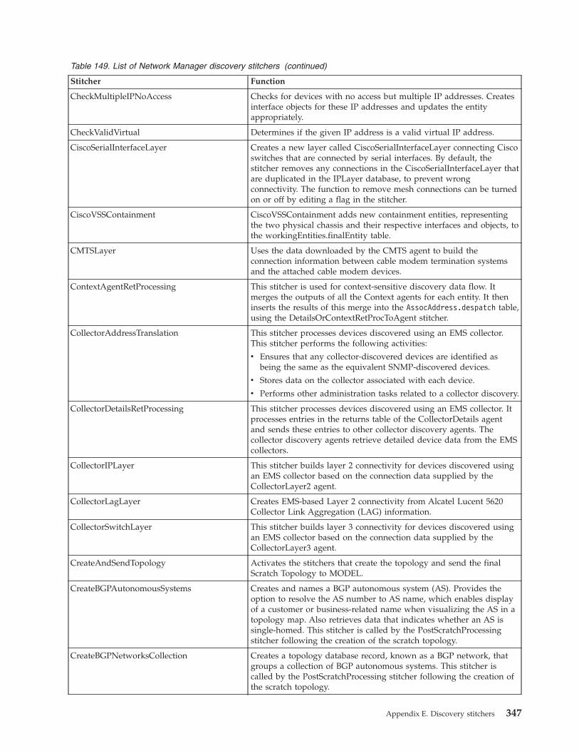
Table 149. List of Network Manager discovery stitchers (continued)
Stitcher Function
CheckMultipleIPNoAccess Checks for devices with no access but multiple IP addresses. Createsinterface objects for these IP addresses and updates the entityappropriately.
CheckValidVirtual Determines if the given IP address is a valid virtual IP address.
CiscoSerialInterfaceLayer Creates a new layer called CiscoSerialInterfaceLayer connecting Ciscoswitches that are connected by serial interfaces. By default, thestitcher removes any connections in the CiscoSerialInterfaceLayer thatare duplicated in the IPLayer database, to prevent wrongconnectivity. The function to remove mesh connections can be turnedon or off by editing a flag in the stitcher.
CiscoVSSContainment CiscoVSSContainment adds new containment entities, representingthe two physical chassis and their respective interfaces and objects, tothe workingEntities.finalEntity table.
CMTSLayer Uses the data downloaded by the CMTS agent to build theconnection information between cable modem termination systemsand the attached cable modem devices.
ContextAgentRetProcessing This stitcher is used for context-sensitive discovery data flow. Itmerges the outputs of all the Context agents for each entity. It theninserts the results of this merge into the AssocAddress.despatch table,using the DetailsOrContextRetProcToAgent stitcher.
CollectorAddressTranslation This stitcher processes devices discovered using an EMS collector.This stitcher performs the following activities:
v Ensures that any collector-discovered devices are identified asbeing the same as the equivalent SNMP-discovered devices.
v Stores data on the collector associated with each device.
v Performs other administration tasks related to a collector discovery.
CollectorDetailsRetProcessing This stitcher processes devices discovered using an EMS collector. Itprocesses entries in the returns table of the CollectorDetails agentand sends these entries to other collector discovery agents. Thecollector discovery agents retrieve detailed device data from the EMScollectors.
CollectorIPLayer This stitcher builds layer 2 connectivity for devices discovered usingan EMS collector based on the connection data supplied by theCollectorLayer2 agent.
CollectorLagLayer Creates EMS-based Layer 2 connectivity from Alcatel Lucent 5620Collector Link Aggregation (LAG) information.
CollectorSwitchLayer This stitcher builds layer 3 connectivity for devices discovered usingan EMS collector based on the connection data supplied by theCollectorLayer3 agent.
CreateAndSendTopology Activates the stitchers that create the topology and send the finalScratch Topology to MODEL.
CreateBGPAutonomousSystems Creates and names a BGP autonomous system (AS). Provides theoption to resolve the AS number to AS name, which enables displayof a customer or business-related name when visualizing the AS in atopology map. Also retrieves data that indicates whether an AS issingle-homed. This stitcher is called by the PostScratchProcessingstitcher following the creation of the scratch topology.
CreateBGPNetworksCollection Creates a topology database record, known as a BGP network, thatgroups a collection of BGP autonomous systems. This stitcher iscalled by the PostScratchProcessing stitcher following the creation ofthe scratch topology.
Appendix E. Discovery stitchers 347
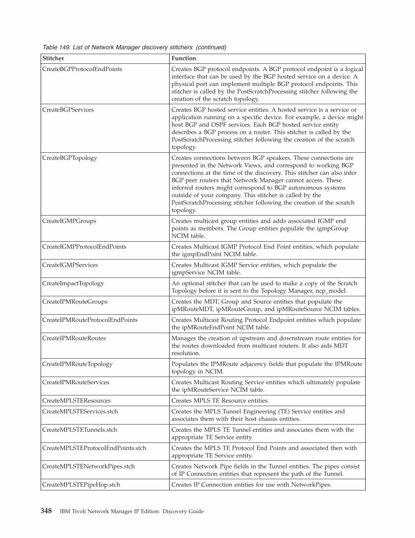
Table 149. List of Network Manager discovery stitchers (continued)
Stitcher Function
CreateBGPProtocolEndPoints Creates BGP protocol endpoints. A BGP protocol endpoint is a logicalinterface that can be used by the BGP hosted service on a device. Aphysical port can implement multiple BGP protocol endpoints. Thisstitcher is called by the PostScratchProcessing stitcher following thecreation of the scratch topology.
CreateBGPServices Creates BGP hosted service entities. A hosted service is a service orapplication running on a specific device. For example, a device mighthost BGP and OSPF services. Each BGP hosted service entitydescribes a BGP process on a router. This stitcher is called by thePostScratchProcessing stitcher following the creation of the scratchtopology.
CreateBGPTopology Creates connections between BGP speakers. These connections arepresented in the Network Views, and correspond to working BGPconnections at the time of the discovery. This stitcher can also inferBGP peer routers that Network Manager cannot access. Theseinferred routers might correspond to BGP autonomous systemsoutside of your company. This stitcher is called by thePostScratchProcessing stitcher following the creation of the scratchtopology.
CreateIGMPGroups Creates multicast group entities and adds associated IGMP endpoints as members. The Group entities populate the igmpGroupNCIM table.
CreateIGMPProtocolEndPoints Creates Multicast IGMP Protocol End Point entities, which populatethe igmpEndPoint NCIM table.
CreateIGMPServices Creates Multicast IGMP Service entities, which populate theigmpService NCIM table.
CreateImpactTopology An optional stitcher that can be used to make a copy of the ScratchTopology before it is sent to the Topology Manager, ncp_model.
CreateIPMRouteGroups Creates the MDT, Group and Source entities that populate theipMRouteMDT, ipMRouteGroup, and ipMRouteSource NCIM tables.
CreateIPMRouteProtocolEndPoints Creates Multicast Routing Protocol Endpoint entities which populatethe ipMRouteEndPoint NCIM table.
CreateIPMRouteRoutes Manages the creation of upstream and downstream route entities forthe routes downloaded from multicast routers. It also aids MDTresolution.
CreateIPMRouteTopology Populates the IPMRoute adjacency fields that populate the IPMRoutetopology in NCIM.
CreateIPMRouteServices Creates Multicast Routing Service entities which ultimately populatethe ipMRouteService NCIM table.
CreateMPLSTEResources Creates MPLS TE Resource entities.
CreateMPLSTEServices.stch Creates the MPLS Tunnel Engineering (TE) Service entities andassociates them with their host chassis entities.
CreateMPLSTETunnels.stch Creates the MPLS TE Tunnel entities and associates them with theappropriate TE Service entity.
CreateMPLSTEProtocolEndPoints.stch Creates the MPLS TE Protocol End Points and associated then withappropriate TE Service entity.
CreateMPLSTENetworkPipes.stch Creates Network Pipe fields in the Tunnel entities. The pipes consistof IP Connection entities that represent the path of the Tunnel.
CreateMPLSTEPipeHop.stch Creates IP Connection entities for use with NetworkPipes.
348 IBM Tivoli Network Manager IP Edition: Discovery Guide

Table 149. List of Network Manager discovery stitchers (continued)
Stitcher Function
CreateMPLSTETopology.stch Adds MPLS TE link fields to interface entities involved in TE Tunnelpaths.
CreateMXGroupCollection Creates collections based on the master IP address for a group ofrouting engines. Called by the PostScratchProcessing stitcher.
CreateNetworkManagementCards This stitcher creates NetworkManagementCard objects.
CreateOSPFAreas Creates and names an OSPF area. This stitcher is called by thePostScratchProcessing stitcher following the creation of the scratchtopology.
CreateOSPFNetworkLSAPseudoNodes Retrieves data associated with OSPF pseudonodes advertised bydesignated routers and builds these pseudonodes in the topology.This overcomes the problem of full meshing when representing OSPFarea in Network Views and enables connections within OSPF areas tobe visualized in a clear, uncluttered manner.
CreateOSPFPointToPointAdjacencies Retrieves data associated with point-to-point connections within anOSPF area and creates these connections in the topology. Theseconnections are shown in Network Views. Only enabled connectionsare shown.
CreateOSPFProtocolEndPoints Creates OSPF protocol endpoints. An OSPF protocol endpoint is alogical interface that can be used by the OSPF hosted service on arouter. This stitcher also gathers data that indicates which OSPF areaan endpoint is in. A physical port can implement multiple OSPFprotocol endpoints. This stitcher is called by thePostScratchProcessing stitcher following the creation of the scratchtopology.
CreateOSPFRoutingDomains Creates a topology database record, known as an OSPF routingdomain, that groups a collection of OSPF areas. This stitcher is calledby the PostScratchProcessing stitcher following the creation of thescratch topology.
CreateOSPFServices Creates OSPF hosted service entities. A hosted service is a service orapplication running on a specific device. For example, a device mighthost BGP and OSPF services. Each OSPF hosted service entitydescribes an OSPF process on a router, and also indicates whetherthe router on which the OSPF service is running is an area borderrouter or an AS border router. This stitcher is called by thePostScratchProcessing stitcher following the creation of the scratchtopology.
CreatePIMNetworksCollection Creates a collection entity to collect PIM enabled routers.
CreatePIMProtocolEndPoints Creates protocol endpoints for each PIM interface.
CreatePIMServices Creates a device level service object representing the state of thehosted multicast service, and a link from the chassis to this serviceobject.
CreatePIMTopology Creates the PIM topology using PIM adjacency information ratherthan m_RouterLinks.
CreateScratchTopology Creates the scratch topology.
CreateStchTimeEvent This stitcher sends events to the disco.events table about progresswithin the data processing phase. For example, the stitcher generatesevents to indicate that the discovery process has started building theworking entities table, and that the discovery process has startedbuilding the containment table. See also, AgentStatus, FinderStatus,and DiscoEventProcessing stitchers.
CreateTrunkConnections Modifies the containment model to take account of VLAN trunks.
Appendix E. Discovery stitchers 349
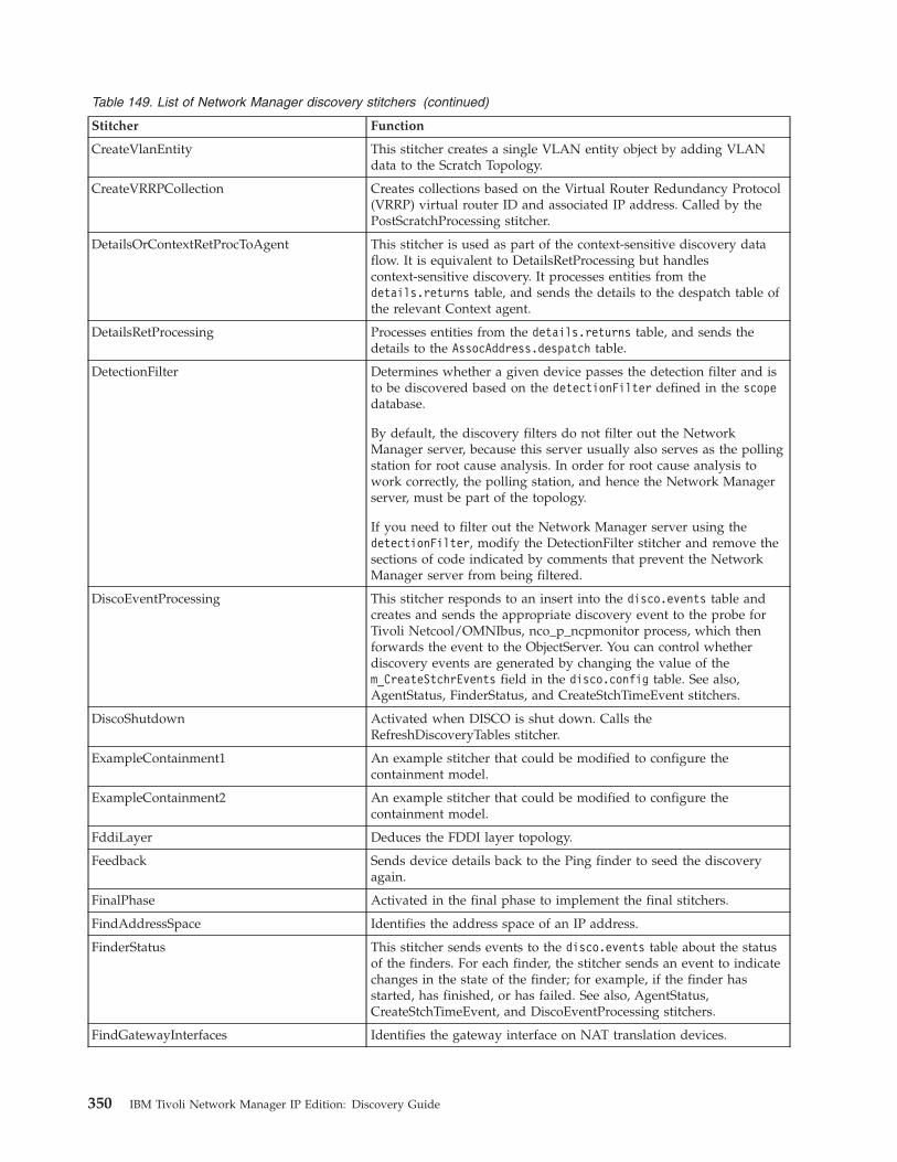
Table 149. List of Network Manager discovery stitchers (continued)
Stitcher Function
CreateVlanEntity This stitcher creates a single VLAN entity object by adding VLANdata to the Scratch Topology.
CreateVRRPCollection Creates collections based on the Virtual Router Redundancy Protocol(VRRP) virtual router ID and associated IP address. Called by thePostScratchProcessing stitcher.
DetailsOrContextRetProcToAgent This stitcher is used as part of the context-sensitive discovery dataflow. It is equivalent to DetailsRetProcessing but handlescontext-sensitive discovery. It processes entities from thedetails.returns table, and sends the details to the despatch table ofthe relevant Context agent.
DetailsRetProcessing Processes entities from the details.returns table, and sends thedetails to the AssocAddress.despatch table.
DetectionFilter Determines whether a given device passes the detection filter and isto be discovered based on the detectionFilter defined in the scopedatabase.
By default, the discovery filters do not filter out the NetworkManager server, because this server usually also serves as the pollingstation for root cause analysis. In order for root cause analysis towork correctly, the polling station, and hence the Network Managerserver, must be part of the topology.
If you need to filter out the Network Manager server using thedetectionFilter, modify the DetectionFilter stitcher and remove thesections of code indicated by comments that prevent the NetworkManager server from being filtered.
DiscoEventProcessing This stitcher responds to an insert into the disco.events table andcreates and sends the appropriate discovery event to the probe forTivoli Netcool/OMNIbus, nco_p_ncpmonitor process, which thenforwards the event to the ObjectServer. You can control whetherdiscovery events are generated by changing the value of them_CreateStchrEvents field in the disco.config table. See also,AgentStatus, FinderStatus, and CreateStchTimeEvent stitchers.
DiscoShutdown Activated when DISCO is shut down. Calls theRefreshDiscoveryTables stitcher.
ExampleContainment1 An example stitcher that could be modified to configure thecontainment model.
ExampleContainment2 An example stitcher that could be modified to configure thecontainment model.
FddiLayer Deduces the FDDI layer topology.
Feedback Sends device details back to the Ping finder to seed the discoveryagain.
FinalPhase Activated in the final phase to implement the final stitchers.
FindAddressSpace Identifies the address space of an IP address.
FinderStatus This stitcher sends events to the disco.events table about the statusof the finders. For each finder, the stitcher sends an event to indicatechanges in the state of the finder; for example, if the finder hasstarted, has finished, or has failed. See also, AgentStatus,CreateStchTimeEvent, and DiscoEventProcessing stitchers.
FindGatewayInterfaces Identifies the gateway interface on NAT translation devices.
350 IBM Tivoli Network Manager IP Edition: Discovery Guide
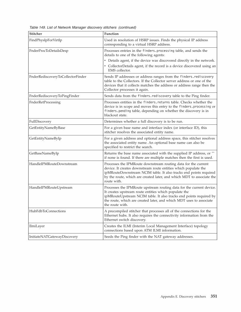
Table 149. List of Network Manager discovery stitchers (continued)
Stitcher Function
FindPhysIpForVirtIp Used in resolution of HSRP issues. Finds the physical IP addresscorresponding to a virtual HSRP address.
FnderProcToDetailsDesp Processes entries in the finders.processing table, and sends thedetails to one of the following agents:
v Details agent, if the device was discovered directly in the network.
v CollectorDetails agent, if the record is a device discovered using anEMS collector.
FnderRediscoveryToCollectorFinder Sends IP addresses or address ranges from the finders.rediscoverytable to the Collectors. If the Collector server address or one of thedevices that it collects matches the address or address range then theCollector processes it again.
FnderRediscoveryToPingFinder Sends data from the finders.rediscovery table to the Ping finder.
FnderRetProcessing Processes entities in the finders.returns table. Checks whether thedevice is in scope and moves this entry to the finders.processing orfinders.pending table, depending on whether the discovery is inblackout state.
FullDiscovery Determines whether a full discovery is to be run.
GetEntityNameByBase For a given base name and interface index (or interface ID), thisstitcher resolves the associated entity name.
GetEntityNameByIp For a given address and optional address space, this stitcher resolvesthe associated entity name. An optional base name can also bespecified to restrict the search.
GetBaseNameByIp Returns the base name associated with the supplied IP address, or ""if none is found. If there are multiple matches then the first is used.
HandleIPMRouteDownstream Processes the IPMRoute downstream routing data for the currentdevice. It creates downstream route entities which populate theipMRouteDownstream NCIM table. It also tracks end points requiredby the route, which are created later, and which MDT to associate theroute with.
HandleIPMRouteUpstream Processes the IPMRoute upstream routing data for the current device.It creates upstream route entities which populate theipMRouteUpstream NCIM table. It also tracks end points required bythe route, which are created later, and which MDT uses to associatethe route with.
HubFdbToConnections A precompiled stitcher that processes all of the connections for theEthernet hubs. It also requires the connectivity information from theEthernet switch discovery.
IlmiLayer Creates the ILMI (Interim Local Management Interface) topologyconnections based upon ATM ILMI information.
InitiateNATGatewayDiscovery Seeds the Ping finder with the NAT gateway addresses.
Appendix E. Discovery stitchers 351
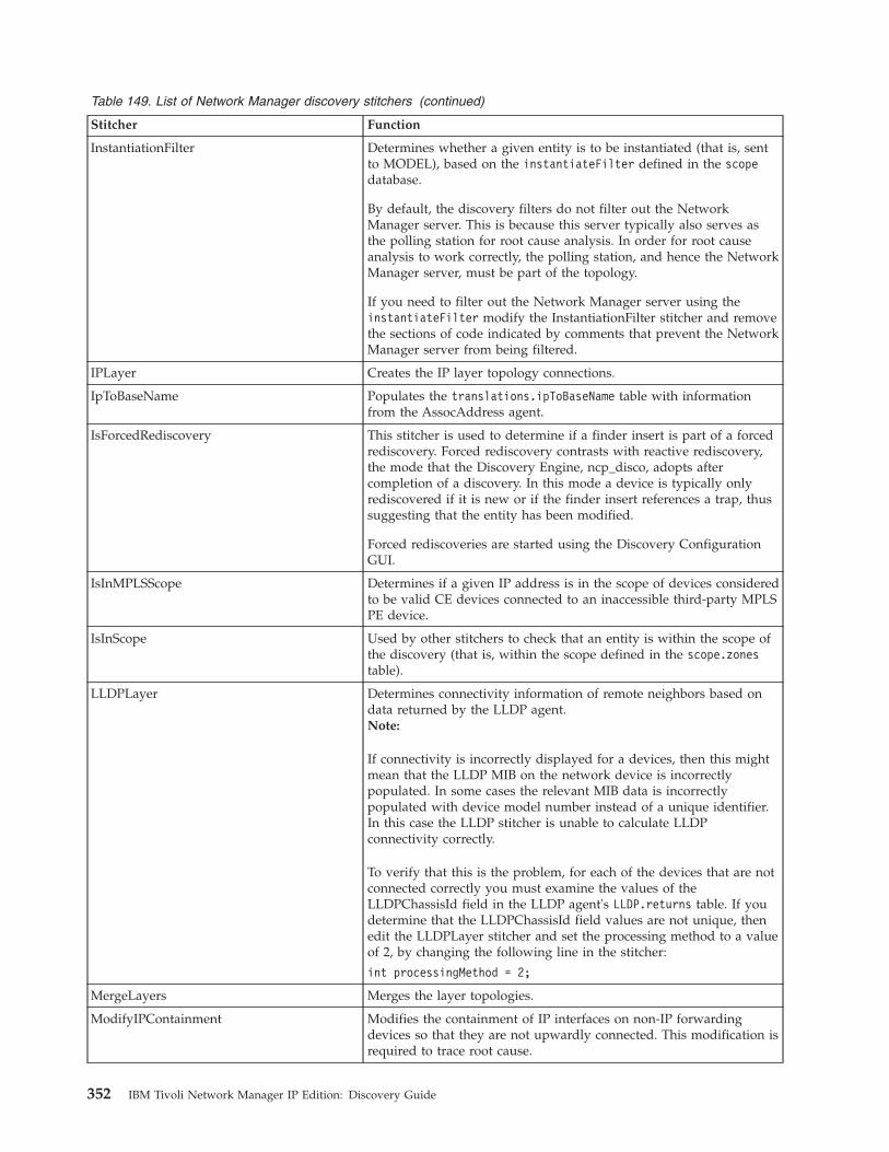
Table 149. List of Network Manager discovery stitchers (continued)
Stitcher Function
InstantiationFilter Determines whether a given entity is to be instantiated (that is, sentto MODEL), based on the instantiateFilter defined in the scopedatabase.
By default, the discovery filters do not filter out the NetworkManager server. This is because this server typically also serves asthe polling station for root cause analysis. In order for root causeanalysis to work correctly, the polling station, and hence the NetworkManager server, must be part of the topology.
If you need to filter out the Network Manager server using theinstantiateFilter modify the InstantiationFilter stitcher and removethe sections of code indicated by comments that prevent the NetworkManager server from being filtered.
IPLayer Creates the IP layer topology connections.
IpToBaseName Populates the translations.ipToBaseName table with informationfrom the AssocAddress agent.
IsForcedRediscovery This stitcher is used to determine if a finder insert is part of a forcedrediscovery. Forced rediscovery contrasts with reactive rediscovery,the mode that the Discovery Engine, ncp_disco, adopts aftercompletion of a discovery. In this mode a device is typically onlyrediscovered if it is new or if the finder insert references a trap, thussuggesting that the entity has been modified.
Forced rediscoveries are started using the Discovery ConfigurationGUI.
IsInMPLSScope Determines if a given IP address is in the scope of devices consideredto be valid CE devices connected to an inaccessible third-party MPLSPE device.
IsInScope Used by other stitchers to check that an entity is within the scope ofthe discovery (that is, within the scope defined in the scope.zonestable).
LLDPLayer Determines connectivity information of remote neighbors based ondata returned by the LLDP agent.Note:
If connectivity is incorrectly displayed for a devices, then this mightmean that the LLDP MIB on the network device is incorrectlypopulated. In some cases the relevant MIB data is incorrectlypopulated with device model number instead of a unique identifier.In this case the LLDP stitcher is unable to calculate LLDPconnectivity correctly.
To verify that this is the problem, for each of the devices that are notconnected correctly you must examine the values of theLLDPChassisId field in the LLDP agent's LLDP.returns table. If youdetermine that the LLDPChassisId field values are not unique, thenedit the LLDPLayer stitcher and set the processing method to a valueof 2, by changing the following line in the stitcher:
int processingMethod = 2;
MergeLayers Merges the layer topologies.
ModifyIPContainment Modifies the containment of IP interfaces on non-IP forwardingdevices so that they are not upwardly connected. This modification isrequired to trace root cause.
352 IBM Tivoli Network Manager IP Edition: Discovery Guide
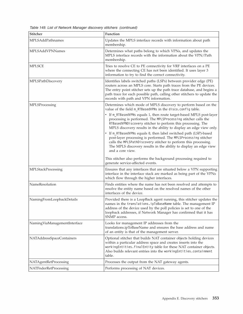
Table 149. List of Network Manager discovery stitchers (continued)
Stitcher Function
MPLSAddPathnames Updates the MPLS interface records with information about pathmembership.
MPLSAddVPNNames Determines what paths belong to which VPNs, and updates theMPLS interface records with the information about the VPN/Pathmembership.
MPLSCE Tries to resolve CE to PE connectivity for VRF interfaces on a PEwhere the connecting CE has not been identified. It uses layer 3information to try to find the correct connectivity.
MPLSPathDiscovery Identifies labels switched paths (LSPs) between provider edge (PE)routers across an MPLS core. Starts path traces from the PE devices.The entry point stitcher sets up the path trace database, and begins apath trace for each possible path, calling other stitchers to update therecords with path and VPN information.
MPLSProcessing Determines which mode of MPLS discovery to perform based on thevalue of the field m_RTBasedVPNs in the disco.config table.
v If m_RTBasedVPNs equals 1, then route target-based MPLS post-layerprocessing is performed. The MPLSProcessing stitcher calls theRTBasedVPNDiscovery stitcher to perform this processing. TheMPLS discovery results in the ability to display an edge view only.
v If m_RTBasedVPNs equals 0, then label switched path (LSP)-basedpost-layer processing is performed. The MPLSProcessing stitchercalls the MPLSPathDiscovery stitcher to perform this processing.The MPLS discovery results in the ability to display an edge viewand a core view.
This stitcher also performs the background processing required togenerate service-affected events.
MPLStackProcessing Ensures that any interfaces that are situated below a VPN supportinginterface in the interface stack are marked as being part of the VPNswhich flow through the higher interfaces.
NameResolution Finds entities where the name has not been resolved and attempts toresolve the entity name based on the resolved names of the otherinterfaces of the device.
NamingFromLoopbackDetails Provided there is a LoopBack agent running, this stitcher updates thenames in the translations.ipToBaseName table. The management IPaddress of the device used by the poll policies is set to one of theloopback addresses, if Network Manager has confirmed that it hasSNMP access.
NamingViaManagementInterface Looks for management IP addresses from thetranslations.ipToBaseName and ensures the base address and nameof an entity is that of the management server.
NATAddressSpaceContainers Optional stitcher that builds NAT container objects holding deviceswithin a particular address space and creates inserts into theworkingEntities.finalEntity table for these NAT container objects.Also builds relevant entries into the workingEntities.containmenttable.
NATAgentRetProcessing Processes the output from the NAT gateway agents.
NATFnderRetProcessing Performs processing of NAT devices.
Appendix E. Discovery stitchers 353
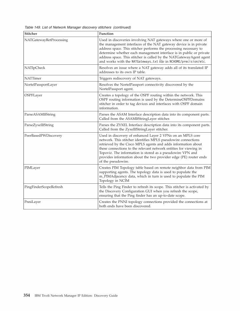
Table 149. List of Network Manager discovery stitchers (continued)
Stitcher Function
NATGatewayRetProcessing Used in discoveries involving NAT gateways where one or more ofthe management interfaces of the NAT gateway device is in privateaddress space. This stitcher performs the processing necessary todetermine whether each management interface is in public or privateaddress space. This stitcher is called by the NATGatewayAgent agentand works with the NATGateways.txt file in NCHOME/precision/etc.
NATIpCheck Resolves an issue where a NAT gateway adds all of its translated IPaddresses to its own IP table.
NATTimer Triggers rediscovery of NAT gateways.
NortelPassportLayer Resolves the NortelPassport connectivity discovered by theNortelPassport agent.
OSPFLayer Creates a topology of the OSPF routing within the network. ThisOSPF routing information is used by the DetermineOSPFDomainsstitcher in order to tag devices and interfaces with OSPF domaininformation.
ParseASAMIfString Parses the ASAM Interface description data into its component parts.Called from the ASAMIfStringLayer stitcher.
ParseZyxelIfString Parses the ZYXEL Interface description data into its component parts.Called from the ZyxelIfStringLayer stitcher.
PeerBasedPWDiscovery Used in discovery of enhanced Layer 2 VPNs on an MPLS corenetwork. This stitcher identifies MPLS pseudowire connectionsretrieved by the Cisco MPLS agents and adds information aboutthese connections to the relevant network entities for viewing inTopoviz. The information is stored as a pseudowire VPN andprovides information about the two provider edge (PE) router endsof the pseudowire.
PIMLayer Creates PIM Topology table based on remote neighbor data from PIMsupporting agents. The topology data is used to populate them_PIMAdjacency data, which in turn is used to populate the PIMTopology in NCIM
PingFinderScopeRefresh Tells the Ping Finder to refresh its scope. This stitcher is activated bythe Discovery Configuration GUI when you refresh the scope,ensuring that the Ping finder has an up-to-date scope.
PnniLayer Creates the PNNI topology connections provided the connections atboth ends have been discovered.
354 IBM Tivoli Network Manager IP Edition: Discovery Guide
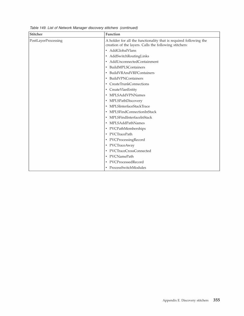
Table 149. List of Network Manager discovery stitchers (continued)
Stitcher Function
PostLayerProcessing A holder for all the functionality that is required following thecreation of the layers. Calls the following stitchers:
v AddGlobalVlans
v AddSwitchRoutingLinks
v AddUnconnectedContainment
v BuildMPLSContainers
v BuildVRAndVRFContainers
v BuildVPNContainers
v CreateTrunkConnections
v CreateVlanEntity
v MPLSAddVPNNames
v MPLSPathDiscovery
v MPLSInterfaceStackTrace
v MPLSFindConnectionInStack
v MPLSFindInterfaceInStack
v MPLSAddPathNames
v PVCPathMemberships
v PVCTracePath
v PVCProcessingRecord
v PVCTraceAway
v PVCTraceCrossConnected
v PVCNamePath
v PVCProcessedRecord
v ProcessSwitchModules
Appendix E. Discovery stitchers 355

Table 149. List of Network Manager discovery stitchers (continued)
Stitcher Function
PostScratchProcessing A holder for functionality to occur following the creation of thescratch topology. Calls the following stitchers:
v CreateNetworkManagementCards
v InstantiationFilter: This stitcher is run as many times as necessaryin order to check whether a given entity must be sent to MODEL.
v SendTopologyToModel
v AddTechnologyType
This stitcher also calls the following stitchers that configureBGP-related information within the topology:
v CreateBGPServices
v CreateBGPProtocolEndPoints
v CreateBGPTopology
v CreateBGPAutonomousSystems
v CreateBGPNetworksCollection
This stitcher also calls the following stitchers that configureOSPF-related information within the topology:
v CreateOSPFServices
v SetOSPFServiceDesignatedStatus
v CreateOSPFProtocolEndPoints
v CreateOSPFNetworkLSAPseudoNodes
v CreateOSPFPointToPointAdjacencies
v CreateOSPFAreas
v CreateOSPFRoutingDomains
PreProcessIGMPEndPointData Creates and populates a temporary table consisting of end-pointinformation for each IGMP-enabled interface and known groups. Italso tracks the Multicast groups for which there is IGMP data. Thisdata is used by other IGMP stitchers to create end point and groupentities.
PresetLayer Can be used to "preset" undiscoverable connections, if required. Thisstitcher is not used by default.
This stitcher contains advanced configuration settings. Any changesmust be made by certified personnel only.
ProcessQinQData Processes QinQ data associated with interfaces and buildsappropriate containment.
ProcessSwitchModules Identifies which switch modules have their own IP addresses.
ProcRemoteConns Takes a record containing a remote neighbor and processes remoteconnections if the agent that discovered it supports indirectconnections.
ProfilingEndFinal
ProfilingPhase1
ProfilingPhase2
ProfilingPhase3
ProfilingStartFinal
These stitchers populate the disco.profilingData table, providingdata on discovery duration, memory usage, and a broad overview ofthe results of the discovery. This information is used in theestimation of scaling, and provides you with an overview ofdiscovery performance.
356 IBM Tivoli Network Manager IP Edition: Discovery Guide
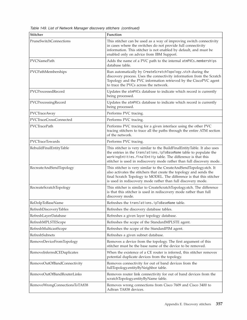
Table 149. List of Network Manager discovery stitchers (continued)
Stitcher Function
PruneSwitchConnections This stitcher can be used as a way of improving switch connectivityin cases where the switches do not provide full connectivityinformation. This stitcher is not enabled by default, and must beenabled only on advice from IBM Support.
PVCNamePath Adds the name of a PVC path to the internal atmPVCs.membershipsdatabase table.
PVCPathMemberships Run automatically by CreateScratchTopology.stch during thediscovery process. Uses the connectivity information from the ScratchTopology and the PVC information retrieved by the CiscoPVC agentto trace the PVCs across the network.
PVCProcessedRecord Updates the atmPVCs database to indicate which record is currentlybeing processed.
PVCProcessingRecord Updates the atmPVCs database to indicate which record is currentlybeing processed.
PVCTraceAway Performs PVC tracing.
PVCTraceCrossConnected Performs PVC tracing.
PVCTracePath Performs PVC tracing for a given interface using the other PVCtracing stitchers to trace all the paths through the entire ATM sectionof the network.
PVCTraceTowards Performs PVC tracing.
RebuildFinalEntityTable This stitcher is very similar to the BuildFinalEntityTable. It also usesthe entries in the translations.ipToBaseName table to populate theworkingEntities.finalEntity table. The difference is that thisstitcher is used in rediscovery mode rather than full discovery mode.
RecreateAndSendTopology This stitcher is very similar to the CreateAndSendTopology.stch. Italso activates the stitchers that create the topology and sends thefinal Scratch Topology to MODEL. The difference is that this stitcheris used in rediscovery mode rather than full discovery mode.
RecreateScratchTopology This stitcher is similar to CreateScratchTopology.stch. The differenceis that this stitcher is used in rediscovery mode rather than fulldiscovery mode.
ReDoIpToBaseName Refreshes the translations.ipToBaseName table.
RefreshDiscoveryTables Refreshes the discovery database tables.
RefreshLayerDatabase Refreshes a given layer topology database.
RefreshMPLSTEScope Refreshes the scope of the StandardMPLSTE agent.
RefreshMulticastScope Refreshes the scope of the StandardPIM agent.
RefreshSubnets Refreshes a given subnet database.
RemoveDeviceFromTopology Removes a device from the topology. The first argument of thisstitcher must be the base name of the device to be removed.
RemoveInferredCEDuplicates When the existence of a CE router is inferred, this stitcher removespotential duplicate devices from the topology.
RemoveOutOfBandConnectivity Removes connectivity for out of band devices from thefullTopology.entityByNeighbor table.
RemoveOutOfBandRouterLinks Removes router link connectivity for out of band devices from thescratchTopology.entityByName table.
RemoveWrongConnectionsToTA838 Removes wrong connections from Cisco 7609 and Cisco 3400 toAdtran TA838 devices.
Appendix E. Discovery stitchers 357
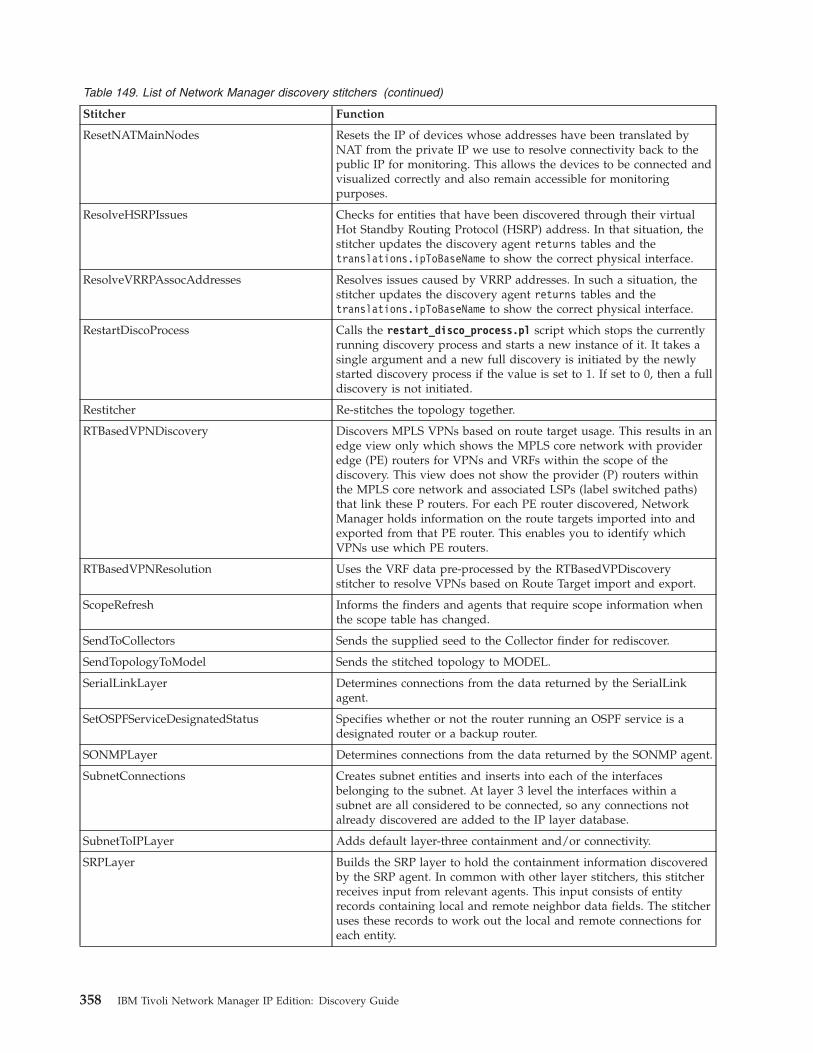
Table 149. List of Network Manager discovery stitchers (continued)
Stitcher Function
ResetNATMainNodes Resets the IP of devices whose addresses have been translated byNAT from the private IP we use to resolve connectivity back to thepublic IP for monitoring. This allows the devices to be connected andvisualized correctly and also remain accessible for monitoringpurposes.
ResolveHSRPIssues Checks for entities that have been discovered through their virtualHot Standby Routing Protocol (HSRP) address. In that situation, thestitcher updates the discovery agent returns tables and thetranslations.ipToBaseName to show the correct physical interface.
ResolveVRRPAssocAddresses Resolves issues caused by VRRP addresses. In such a situation, thestitcher updates the discovery agent returns tables and thetranslations.ipToBaseName to show the correct physical interface.
RestartDiscoProcess Calls the restart_disco_process.pl script which stops the currentlyrunning discovery process and starts a new instance of it. It takes asingle argument and a new full discovery is initiated by the newlystarted discovery process if the value is set to 1. If set to 0, then a fulldiscovery is not initiated.
Restitcher Re-stitches the topology together.
RTBasedVPNDiscovery Discovers MPLS VPNs based on route target usage. This results in anedge view only which shows the MPLS core network with provideredge (PE) routers for VPNs and VRFs within the scope of thediscovery. This view does not show the provider (P) routers withinthe MPLS core network and associated LSPs (label switched paths)that link these P routers. For each PE router discovered, NetworkManager holds information on the route targets imported into andexported from that PE router. This enables you to identify whichVPNs use which PE routers.
RTBasedVPNResolution Uses the VRF data pre-processed by the RTBasedVPDiscoverystitcher to resolve VPNs based on Route Target import and export.
ScopeRefresh Informs the finders and agents that require scope information whenthe scope table has changed.
SendToCollectors Sends the supplied seed to the Collector finder for rediscover.
SendTopologyToModel Sends the stitched topology to MODEL.
SerialLinkLayer Determines connections from the data returned by the SerialLinkagent.
SetOSPFServiceDesignatedStatus Specifies whether or not the router running an OSPF service is adesignated router or a backup router.
SONMPLayer Determines connections from the data returned by the SONMP agent.
SubnetConnections Creates subnet entities and inserts into each of the interfacesbelonging to the subnet. At layer 3 level the interfaces within asubnet are all considered to be connected, so any connections notalready discovered are added to the IP layer database.
SubnetToIPLayer Adds default layer-three containment and/or connectivity.
SRPLayer Builds the SRP layer to hold the containment information discoveredby the SRP agent. In common with other layer stitchers, this stitcherreceives input from relevant agents. This input consists of entityrecords containing local and remote neighbor data fields. The stitcheruses these records to work out the local and remote connections foreach entity.
358 IBM Tivoli Network Manager IP Edition: Discovery Guide
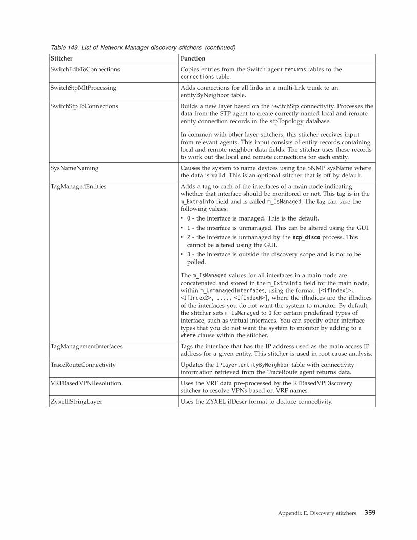
Table 149. List of Network Manager discovery stitchers (continued)
Stitcher Function
SwitchFdbToConnections Copies entries from the Switch agent returns tables to theconnections table.
SwitchStpMltProcessing Adds connections for all links in a multi-link trunk to anentityByNeighbor table.
SwitchStpToConnections Builds a new layer based on the SwitchStp connectivity. Processes thedata from the STP agent to create correctly named local and remoteentity connection records in the stpTopology database.
In common with other layer stitchers, this stitcher receives inputfrom relevant agents. This input consists of entity records containinglocal and remote neighbor data fields. The stitcher uses these recordsto work out the local and remote connections for each entity.
SysNameNaming Causes the system to name devices using the SNMP sysName wherethe data is valid. This is an optional stitcher that is off by default.
TagManagedEntities Adds a tag to each of the interfaces of a main node indicatingwhether that interface should be monitored or not. This tag is in them_ExtraInfo field and is called m_IsManaged. The tag can take thefollowing values:
v 0 - the interface is managed. This is the default.
v 1 - the interface is unmanaged. This can be altered using the GUI.
v 2 - the interface is unmanaged by the ncp_disco process. Thiscannot be altered using the GUI.
v 3 - the interface is outside the discovery scope and is not to bepolled.
The m_IsManaged values for all interfaces in a main node areconcatenated and stored in the m_ExtraInfo field for the main node,within m_UnmanagedInterfaces, using the format: [<ifIndex1>,<IfIndex2>, ..... <IfIndexN>], where the ifIndices are the ifIndicesof the interfaces you do not want the system to monitor. By default,the stitcher sets m_IsManaged to 0 for certain predefined types ofinterface, such as virtual interfaces. You can specify other interfacetypes that you do not want the system to monitor by adding to awhere clause within the stitcher.
TagManagementInterfaces Tags the interface that has the IP address used as the main access IPaddress for a given entity. This stitcher is used in root cause analysis.
TraceRouteConnectivity Updates the IPLayer.entityByNeighbor table with connectivityinformation retrieved from the TraceRoute agent returns data.
VRFBasedVPNResolution Uses the VRF data pre-processed by the RTBasedVPDiscoverystitcher to resolve VPNs based on VRF names.
ZyxelIfStringLayer Uses the ZYXEL ifDescr format to deduce connectivity.
Appendix E. Discovery stitchers 359

Related concepts:“Filters” on page 5Use prediscovery filters to increase the efficiency of discovery and post-discoveryfilters to prevent instantiation of devices.“Process flow for creating discovery events” on page 164Discovery events are created during the discovery process showing the progress ofagents, stitchers, and finders. These events are sent to and stored in TivoliNetcool/OMNIbus and can be viewed using the Web GUI.Related tasks:“Setting discovery filters” on page 28Use filters to filter out devices either before discovery or after discovery. You canfilter out devices based on a variety of criteria, including location, technology, andmanufacturer. Filters provide additional restrictions to those defined in the scopezones.“Scoping discovery” on page 17To scope the discovery, define the zones of the network (that is, subnet ranges) thatyou want to include in the discovery, and the zones that you want to exclude.
360 IBM Tivoli Network Manager IP Edition: Discovery Guide
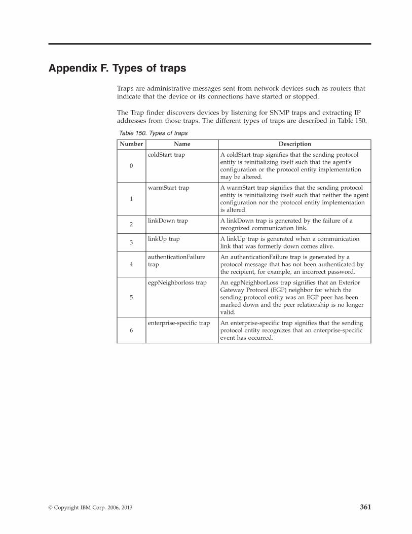
Appendix F. Types of traps
Traps are administrative messages sent from network devices such as routers thatindicate that the device or its connections have started or stopped.
The Trap finder discovers devices by listening for SNMP traps and extracting IPaddresses from those traps. The different types of traps are described in Table 150.
Table 150. Types of traps
Number Name Description
0
coldStart trap A coldStart trap signifies that the sending protocolentity is reinitializing itself such that the agent'sconfiguration or the protocol entity implementationmay be altered.
1
warmStart trap A warmStart trap signifies that the sending protocolentity is reinitializing itself such that neither the agentconfiguration nor the protocol entity implementationis altered.
2linkDown trap A linkDown trap is generated by the failure of a
recognized communication link.
3linkUp trap A linkUp trap is generated when a communication
link that was formerly down comes alive.
4authenticationFailuretrap
An authenticationFailure trap is generated by aprotocol message that has not been authenticated bythe recipient, for example, an incorrect password.
5
egpNeighborloss trap An egpNeighborLoss trap signifies that an ExteriorGateway Protocol (EGP) neighbor for which thesending protocol entity was an EGP peer has beenmarked down and the peer relationship is no longervalid.
6enterprise-specific trap An enterprise-specific trap signifies that the sending
protocol entity recognizes that an enterprise-specificevent has occurred.
© Copyright IBM Corp. 2006, 2013 361

362 IBM Tivoli Network Manager IP Edition: Discovery Guide
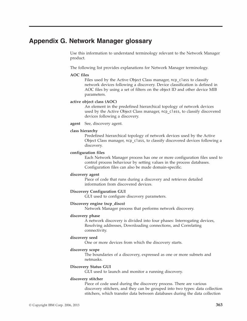
Appendix G. Network Manager glossary
Use this information to understand terminology relevant to the Network Managerproduct.
The following list provides explanations for Network Manager terminology.
AOC filesFiles used by the Active Object Class manager, ncp_class to classifynetwork devices following a discovery. Device classification is defined inAOC files by using a set of filters on the object ID and other device MIBparameters.
active object class (AOC)An element in the predefined hierarchical topology of network devicesused by the Active Object Class manager, ncp_class, to classify discovereddevices following a discovery.
agent See, discovery agent.
class hierarchyPredefined hierarchical topology of network devices used by the ActiveObject Class manager, ncp_class, to classify discovered devices following adiscovery.
configuration filesEach Network Manager process has one or more configuration files used tocontrol process behaviour by setting values in the process databases.Configuration files can also be made domain-specific.
discovery agentPiece of code that runs during a discovery and retrieves detailedinformation from discovered devices.
Discovery Configuration GUIGUI used to configure discovery parameters.
Discovery engine (ncp_disco)Network Manager process that performs network discovery.
discovery phaseA network discovery is divided into four phases: Interrogating devices,Resolving addresses, Downloading connections, and Correlatingconnectivity.
discovery seedOne or more devices from which the discovery starts.
discovery scopeThe boundaries of a discovery, expressed as one or more subnets andnetmasks.
Discovery Status GUIGUI used to launch and monitor a running discovery.
discovery stitcherPiece of code used during the discovery process. There are variousdiscovery stitchers, and they can be grouped into two types: data collectionstitchers, which transfer data between databases during the data collection
© Copyright IBM Corp. 2006, 2013 363
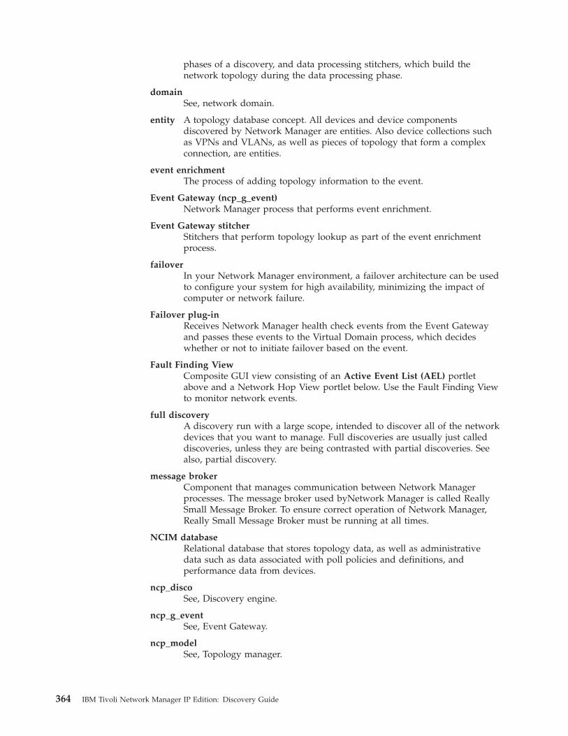
phases of a discovery, and data processing stitchers, which build thenetwork topology during the data processing phase.
domainSee, network domain.
entity A topology database concept. All devices and device componentsdiscovered by Network Manager are entities. Also device collections suchas VPNs and VLANs, as well as pieces of topology that form a complexconnection, are entities.
event enrichmentThe process of adding topology information to the event.
Event Gateway (ncp_g_event)Network Manager process that performs event enrichment.
Event Gateway stitcherStitchers that perform topology lookup as part of the event enrichmentprocess.
failoverIn your Network Manager environment, a failover architecture can be usedto configure your system for high availability, minimizing the impact ofcomputer or network failure.
Failover plug-inReceives Network Manager health check events from the Event Gatewayand passes these events to the Virtual Domain process, which decideswhether or not to initiate failover based on the event.
Fault Finding ViewComposite GUI view consisting of an Active Event List (AEL) portletabove and a Network Hop View portlet below. Use the Fault Finding Viewto monitor network events.
full discoveryA discovery run with a large scope, intended to discover all of the networkdevices that you want to manage. Full discoveries are usually just calleddiscoveries, unless they are being contrasted with partial discoveries. Seealso, partial discovery.
message brokerComponent that manages communication between Network Managerprocesses. The message broker used byNetwork Manager is called ReallySmall Message Broker. To ensure correct operation of Network Manager,Really Small Message Broker must be running at all times.
NCIM databaseRelational database that stores topology data, as well as administrativedata such as data associated with poll policies and definitions, andperformance data from devices.
ncp_discoSee, Discovery engine.
ncp_g_eventSee, Event Gateway.
ncp_modelSee, Topology manager.
364 IBM Tivoli Network Manager IP Edition: Discovery Guide
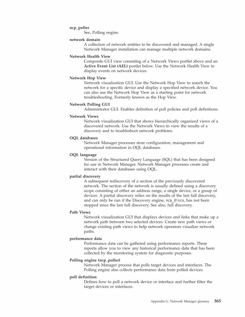
ncp_pollerSee, Polling engine.
network domainA collection of network entities to be discovered and managed. A singleNetwork Manager installation can manage multiple network domains.
Network Health ViewComposite GUI view consisting of a Network Views portlet above and anActive Event List (AEL) portlet below. Use the Network Health View todisplay events on network devices.
Network Hop ViewNetwork visualization GUI. Use the Network Hop View to search thenetwork for a specific device and display a specified network device. Youcan also use the Network Hop View as a starting point for networktroubleshooting. Formerly known as the Hop View.
Network Polling GUIAdministrator GUI. Enables definition of poll policies and poll definitions.
Network ViewsNetwork visualization GUI that shows hierarchically organized views of adiscovered network. Use the Network Views to view the results of adiscovery and to troubleshoot network problems.
OQL databasesNetwork Manager processes store configuration, management andoperational information in OQL databases.
OQL languageVersion of the Structured Query Language (SQL) that has been designedfor use in Network Manager. Network Manager processes create andinteract with their databases using OQL.
partial discoveryA subsequent rediscovery of a section of the previously discoverednetwork. The section of the network is usually defined using a discoveryscope consisting of either an address range, a single device, or a group ofdevices. A partial discovery relies on the results of the last full discovery,and can only be run if the Discovery engine, ncp_disco, has not beenstopped since the last full discovery. See also, full discovery.
Path ViewsNetwork visualization GUI that displays devices and links that make up anetwork path between two selected devices. Create new path views orchange existing path views to help network operators visualize networkpaths.
performance dataPerformance data can be gathered using performance reports. Thesereports allow you to view any historical performance data that has beencollected by the monitoring system for diagnostic purposes.
Polling engine (ncp_poller)Network Manager process that polls target devices and interfaces. ThePolling engine also collects performance data from polled devices.
poll definitionDefines how to poll a network device or interface and further filter thetarget devices or interfaces.
Appendix G. Network Manager glossary 365
poll policyDefines which devices to poll. Also defines other attributes of a poll suchas poll frequency.
Probe for Tivoli Netcool/OMNIbus (nco_p_ncpmonitor)Acquires and processes the events that are generated by Network Managerpolls and processes, and forwards these events to the ObjectServer.
RCA plug-inBased on data in the event and based on the discovered topology, attemptsto identify events that are caused by or cause other events using rulescoded in RCA stitchers.
RCA stitcherStitchers that process a trigger event as it passes through the RCA plug-in.
root-cause analysis (RCA)The process of determining the root cause of one or more device alerts.
SNMP MIB BrowserGUI that retrieves MIB variable information from network devices tosupport diagnosis of network problems.
SNMP MIB GrapherGUI that displays a real-time graph of MIB variables for a device and ussethe graph for fault analysis and resolution of network problems.
stitcherCode used in the following processes: discovery, event enrichment, androot-cause analysis. See also, discovery stitcher, Event Gateway stitcher,and RCA stitcher.
Structure BrowserGUI that enables you to investigate the health of device components inorder to isolate faults within a network device.
Topology Manager (ncp_model)Stores the topology data following a discovery and sends the topologydata to the NCIM topology database where it can be queried using SQL.
WebToolsSpecialized data retrieval tools that retrieve data from network devices andcan be launched from the network visualization GUIs, Network Views andNetwork Hop View, or by specifying a URL in a web browser.
366 IBM Tivoli Network Manager IP Edition: Discovery Guide
Notices
This information applies to the PDF documentation set for IBM Tivoli NetworkManager IP Edition 3.9.
This information was developed for products and services offered in the U.S.A.
IBM may not offer the products, services, or features discussed in this document inother countries. Consult your local IBM representative for information on theproducts and services currently available in your area. Any reference to an IBMproduct, program, or service is not intended to state or imply that only that IBMproduct, program, or service may be used. Any functionally equivalent product,program, or service that does not infringe any IBM intellectual property right maybe used instead. However, it is the user's responsibility to evaluate and verify theoperation of any non-IBM product, program, or service.
IBM may have patents or pending patent applications covering subject matterdescribed in this document. The furnishing of this document does not grant youany license to these patents. You can send license inquiries, in writing, to:
IBM Director of LicensingIBM CorporationNorth Castle DriveArmonk, NY 10504-1785U.S.A.
For license inquiries regarding double-byte character set (DBCS) information,contact the IBM Intellectual Property Department in your country or sendinquiries, in writing, to:
Intellectual Property LicensingLegal and Intellectual Property LawIBM Japan, Ltd.19-21, Nihonbashi-Hakozakicho, Chuo-kuTokyo 103-8510, Japan
The following paragraph does not apply to the United Kingdom or any othercountry where such provisions are inconsistent with local law: INTERNATIONALBUSINESS MACHINES CORPORATION PROVIDES THIS PUBLICATION "AS IS"WITHOUT WARRANTY OF ANY KIND, EITHER EXPRESS OR IMPLIED,INCLUDING, BUT NOT LIMITED TO, THE IMPLIED WARRANTIES OFNON-INFRINGEMENT, MERCHANTABILITY OR FITNESS FOR A PARTICULARPURPOSE. Some states do not allow disclaimer of express or implied warranties incertain transactions, therefore, this statement may not apply to you.
This information could include technical inaccuracies or typographical errors.Changes are periodically made to the information herein; these changes will beincorporated in new editions of the publication. IBM may make improvementsand/or changes in the product(s) and/or the program(s) described in thispublication at any time without notice.
Any references in this information to non-IBM Web sites are provided forconvenience only and do not in any manner serve as an endorsement of those Web
© Copyright IBM Corp. 2006, 2013 367
sites. The materials at those Web sites are not part of the materials for this IBMproduct and use of those Web sites is at your own risk.
IBM may use or distribute any of the information you supply in any way itbelieves appropriate without incurring any obligation to you.
Licensees of this program who wish to have information about it for the purposeof enabling: (i) the exchange of information between independently createdprograms and other programs (including this one) and (ii) the mutual use of theinformation which has been exchanged, should contact:
IBM Corporation958/NH04IBM Centre, St Leonards601 Pacific HwySt Leonards, NSW, 2069AustraliaIBM Corporation896471/H128B76 Upper GroundLondonSE1 9PZUnited KingdomIBM CorporationJBF1/SOM1 294Route 100Somers, NY, 10589-0100United States of America
Such information may be available, subject to appropriate terms and conditions,including in some cases, payment of a fee.
The licensed program described in this document and all licensed materialavailable for it are provided by IBM under terms of the IBM Customer Agreement,IBM International Program License Agreement or any equivalent agreementbetween us.
Any performance data contained herein was determined in a controlledenvironment. Therefore, the results obtained in other operating environments mayvary significantly. Some measurements may have been made on development-levelsystems and there is no guarantee that these measurements will be the same ongenerally available systems. Furthermore, some measurements may have beenestimated through extrapolation. Actual results may vary. Users of this documentshould verify the applicable data for their specific environment.
Information concerning non-IBM products was obtained from the suppliers ofthose products, their published announcements or other publicly available sources.IBM has not tested those products and cannot confirm the accuracy ofperformance, compatibility or any other claims related to non-IBM products.Questions on the capabilities of non-IBM products should be addressed to thesuppliers of those products.
This information contains examples of data and reports used in daily businessoperations. To illustrate them as completely as possible, the examples include the
368 IBM Tivoli Network Manager IP Edition: Discovery Guide
names of individuals, companies, brands, and products. All of these names arefictitious and any similarity to the names and addresses used by an actual businessenterprise is entirely coincidental.
COPYRIGHT LICENSE:
This information contains sample application programs in source language, whichillustrate programming techniques on various operating platforms. You may copy,modify, and distribute these sample programs in any form without payment toIBM, for the purposes of developing, using, marketing or distributing applicationprograms conforming to the application programming interface for the operatingplatform for which the sample programs are written. These examples have notbeen thoroughly tested under all conditions. IBM, therefore, cannot guarantee orimply reliability, serviceability, or function of these programs.
TrademarksThe terms in Table 151 are trademarks of International Business MachinesCorporation in the United States, other countries, or both:
Table 151. IBM trademarks
AIX iSeries RDN
ClearQuest Lotus SecureWay
Cognos Netcool solidDB
Current NetView System z
DB2 Notes Tivoli
developerWorks OMEGAMON WebSphere
EnterpriseStorage Server
PowerVM z/OS
IBM PR/SM z/VM
Informix pSeries zSeries
Intel, Intel logo, Intel Inside, Intel Inside logo, Intel Centrino, Intel Centrino logo,Celeron, Intel Xeon, Intel SpeedStep, Itanium, and Pentium are trademarks orregistered trademarks of Intel Corporation or its subsidiaries in the United Statesand other countries.
Java™ and all Java-based trademarks and logos are trademarks orregistered trademarks of Oracle and/or its affiliates.
Linux is a registered trademark of Linus Torvalds in the United States, othercountries, or both.
Notices 369

UNIX is a registered trademark of The Open Group in the United States and othercountries.
Microsoft, Windows, Windows NT, and the Windows logo are trademarks ofMicrosoft Corporation in the United States, other countries, or both.
370 IBM Tivoli Network Manager IP Edition: Discovery Guide
Index
Aabout this publication ixaccess databases 210accessibility xiiiadvanced discovery parameters
configuring 37advanced partial discovery settings 157agents 4, 303
activating with DiscoveryConfiguration GUI 27
and retrieved data 305changing agent type 81CiscoNATTelnet 123collector discovery agents,
enabling 101enabling partial discovery 156identifying failed agents 167NATGateway 125NATNetScreen 123NATTextFileAgent 123troubleshooting 165
agents database schema 217agents table 193agents.definitions database table
schema 217agents.definitions table 217agents.status database table schema 218agents.status table 218agents.victims database table
schema 217agents.victims table 217AgentTemplate database synopsis 274Alcatel5620Csv 96Alcatel5620SamSoap 93Alcatel5620SamSoapFindToFile 94AOC
applying AOC changes to thetopology 148
EndNode class 150NetworkDevice class 151
AOC file samples 150AOC specific to device class 152AOCs
creating 148editing 148
ARP helper database 248ARPhelper database 234associated device addresses,
discovering 289ATM devices
discovering connectivity among 321audience for this publication ixautomatic discovery
definition of 1automatic discovery, configuring 156
Bbasic device information
discovering 297
broadcastof discovery data to other
processes 293broadcast pinging 37
Ccached data
ignored 271CE routers
inferring the existence of 109checklist for discovery 11choosing a scoped or unscoped
discovery 12ciscoFrameRelay database table
schema 258ciscoFrameRelay table 258classifying network devices 147collector
Alcatel5620Csv 96Alcatel5620SamSoap 93Alcatel5620SamSoapFindToFile 94GenericSVC 98
collector discovery agentsenabling 101
Collector finderseeding with configuration file 56
collectorsconfiguration files 101configuring 91locations 101overview 89starting on the command line 99
comparing progress of discovery from theGUI 132
complex discovery queriessamples 142
config table 183configurable discovery data flow 294configuration databases 183configuration files
DiscoAgentReturns.filter 55DiscoAgents.cfg 53DiscoARPHelperSchema.cfg 55DiscoDNSHelperSchema.cfg 56DiscoFileFinderParseRules.cfg 58DiscoHelperServerSchema.cfg 60DiscoPingFinderSeeds.cfg 61DiscoPingHelperSchema.cfg 62DiscoSchema.cfg
context-sensitive discovery,enabling 63
File finder devices, pinging 63DiscoScope.cfg 64DiscoSnmpHelperSchema.cfg 70DiscoXmlRpcHelperSchema.cfg 74helper databases 248helpers 339SnmpStackSecurityInfo.cfg 75TelnetStackPasswords.cfg 78
Configuration Summary windowcompleting discovery 16reviewing your settings 16
configuring advanced discoveryparameters 37
configuring advanced partial discoverysettings 157
configuring DNS helpers 31configuring feedback settings for partial
discovery 157configuring multicast discovery 34, 35configuring Network Address
Translation 33containers table 268containment database table schema 260containment information
discovery of 325containment table 260contents of this publication ixcontext agent
within the discovery process 288Context agent
enabling 8, 102context-sensitive discovery
configuring 8, 102limitations 8, 102
context-sensitive discovery agents 329context-sensitive discovery, enabling 63conventions, typeface xivcore view of MPLS network 103crashed agents 167creating filters 28custom tags
enabling network visualization basedon 178
enabling polling based on 178
Ddaemons (Helper System) 340data collection stage 280
first phase 281second phase 281The impact of the stages and phases
approach on DISCO processes 281third phase 281
data flowconfiguring 216modifying 216starting stitchers in 216
data processing stage 280, 281database schema
SNMP helper 241databases
agents 217ARP helper 248ARPhelper 234Details 223discovery 183DNS helper
example configuration 236
© Copyright IBM Corp. 2006, 2013 371
databases (continued)DNS helper database
example configuration 236DNShelper 248failover 270finders 220MODEL 265Ping helper 249process management 216rediscoveryStore 265scope 201SNMP helper 250stitchers 218subprocess 220Telnet helper 251tracking discovery databases 253translations 253workingEntities 259XMLRPC helper 252
databases for helpers 248dataLibrary table 265dead agents 167debugging a NAT discovery 128deleting filters 28despatch table 275detailed device information
discovering 298Details database schema 223Details.despatch database table
schema 224Details.despatch table 224Details.returns database table
schema 224detectionFilter table 201device 161device access
configuring 4configuring with GUI 23
device class hierarchy, changing 147device connectivity
discovering 291device detection
preventing with a filter 209device existence
discovering 295device existence, discovering 286devices
detection, restricting 64determining classification of 147instantiation, restricting 64interrogation, restricting 64listing devices in use 147
devices or subnetsdiscovering manually 156
differentiating identical IP addresses indifferent VPNs 107
DISCOconfiguration databases 183
Disco plug-in 156disco.agents database table schema 193disco.agents table
example configuration of 200disco.config database table schema 183disco.config table
example configuration 199disco.dynamicConfigFiles database table
schema 195
disco.events database table schema 197disco.filterCustomTags database table
schema 198disco.ipCustomTags database table
schema 198disco.managedProcesses
example configuration 199disco.managedProcesses database table
schema 190disco.NATStatus database table
schema 195disco.profilingData database table
schema 196disco.status database table schema 191disco.tempData database table
schema 196DiscoAgentProcLayerAddLocalTags{}
section 84DiscoAgentProcLayerAddTags{}
section 84DiscoAgentReturns.filter configuration
file 55DiscoAgents.cfg configuration file 53DiscoARPHelperSchema.cfg 55DiscoConfig.cfg
context-sensitive discovery,enabling 63
File finder devices, pinging 63DiscoDNSHelperSchema.cfg 56DiscoFileFinderParseRules.cfg
configuration file 58DiscoHelperServerSchema.cfg
configuration file 60DiscoICMPGetTrace(); 83DiscoPingFinderSeeds.cfg configuration
file 61DiscoPingHelperSchema.cfg configuration
file 62DiscoScope.cfg configuration file 64DiscoSnmpGetAccessParameters(); 83DiscoSnmpGetNextResponse(); 82DiscoSnmpGetResponse(); 82DiscoSnmpHelperSchema.cfg
configuration file 70discovering associated device
addresses 289discovering device details
context-sensitive 288standard 287
discovering devices or subnetsmanually 156
discovering the network using thecommand-line interface 47
discovery 34, 35, 161about 1advanced settings 8agent progress, monitoring from the
GUI 134agent status 134agents 4cache 168choosing scoped or unscoped 12comparing with previous 132components of 277configuring advanced discovery
parameters 37configuring DNS helpers 31
discovery (continued)configuring multicast discovery 34configuring Network Address
Translation 33configuring remote neighbor partial
discovery settings 158context-sensitive
configuring 8, 102cycles 285definition of 1discovery agent status 134discovery cache 168EMS discoveries 88EMS discovery 91enabling discovery agents 27filter values 30identifying failed agents 167Layer 2 14Layer 3 14managing network discovery 11manual
using the GUI 156monitoring 131monitoring discovery agent progress
with GUI 134monitoring ping finder progress with
GUI 133monitoring with GUI 131MPLS 104
configuring discoveries for 102MPLS discovery 105MPLS discovery methods 108NAT 128NAT discovery 115
activating 33deactivating 33
NAT environment discovery 118new discovery 168optimizing 15partial discovery from command
line 160partial matching 294ping finder progress, monitoring from
the GUI 133ping finder status 133planning for 11post-configuration tasks for 128progress, comparing from the
GUI 132progress, monitoring from the
GUI 131queries
complex 142rediscovery 299scheduling 155scoped discovery 12scoping multicast discovery 35seeding 20seeding File finder 20seeding Ping finder 20setting discovery filters 5setting discovery parameters 1setting SNMP access 23setting Telnet access 23specialized 9specialized discoveries 88specifying type of 14
372 IBM Tivoli Network Manager IP Edition: Discovery Guide
discovery (continued)starting with the Discovery
Configuration GUI 43status 131step-by-step description of 285stopping with the Discovery
Configuration GUI 43troubleshooting
idle 168illegal characters 169missing devices 167
troubleshooting a long discovery 165unscoped discovery 12using EMS integration 295using the command-line interface 47with the wizard 12
discovery agent definition filekeywords 305
discovery agent progress, monitoringfrom the GUI 134
discovery agents 303Associated Address agent 303, 304ATM 321containment 325context-sensitive agents 329Details agent 303discovery agent databases
agentTemplate database 303Ethernet switches 311extra information 81filtering devices 50identifying failed agents 167IP layer agents, recommended 336layer 2 338layer 3 316, 338MPLS 322multicast 323NAT gateways 324on other protocols 327protocol-specific 336routing protocol discovery
agents 320selecting 336specialized agents 337standard agents 336task-specific 330topology data stored in an EMS 320troubleshooting 165types 311
discovery agents, processing informationfrom 300
discovery configurationadvanced options 293completing 16reviewing 16
Discovery Configuration GUI 17configuring advanced discovery
parameters 37configuring DNS helpers 31configuring multicast discovery 34,
35configuring Network Address
Translation 33defining discovery scope 17enabling discovery agents 27limitations for context-sensitive
discovery 8, 102
Discovery Configuration GUI (continued)overview 17seeding a discovery 20seeding File finder 20seeding Ping finder 20setting discovery filters 5setting SNMP access 23setting Telnet access 23starting discovery 43stopping discovery 43
discovery databroadcast to other processes 293
discovery databases 183discovery parameters
GUI 17mapping to schemas and tables 46
discovery processoverview 277
discovery progressmonitoring from the command
line 136discovery progress, comparing from the
GUI 132discovery progress, monitoring from the
GUI 131discovery scope
adding new scope zone 17databases 201defining multiple inclusion zones 19defining NAT zones 121defining using Discovery
Configuration GUI 17deleting scope zone 17devices with out-of-scope
interfaces 70editing existing scope zone 17restricting device interrogation 64restricting instantiation 64sensitive devices 2types of scoping 3
discovery stages and phasesdata collection 280data processing 280overview 280
discovery timing 278discovery zones
restricting discovery 3DNS
configuring 7DNS helper
configuring with configurationfile 56
configuring with GUI 31DNS Helper
advanced parameters 37DNS helper database 248DNS helpers, configuring 31DNSHelper.configuration database table
schema 56DNShelper.methods database table
schema 56Domain Name System
configuring 7doNotCache table 273dynamicConfigFiles table 195
Eedge view of MPLS network 103editing filters 28education
see Tivoli technical training xivElement Management Systems
configuring discovery of 91EMS
configuring discovery of 91EMS discoveries
configuring 88EMS discovery
seeding with configuration file 100EMS integration
overview 89EMS Integration
components of 90enabling
network visualization based oncustom tags 178
polling based on custom tags 178enabling discovery agents 27end nodes
filtering 14EndNode class 150enhanced layer 2 MPLS VPNs 103entityByName database table
schema 263entityByName table 263, 266entityByNeighbor database table
schema 262entityByNeighbor table 262, 267environment variables, notation xivevents 104events table 197example
GetCustomTag.stch 177NAT discovery configuration 125
Ffailed agents 167failover
database 270database schema 271enabling 270
failover database configurationexample 273
failover.config database tableschema 271
failover.config table 271example configuration 274
failover.doNotCache database tableschema 273
failover.doNotCache tableexample configuration 274
failover.findRateDetails database tableschema 272
failover.restartPhaseAction database tableschema 273
failover.status database tableschema 272
failover.status table 272fddi database table schema 259fddi table 259file finder 171
Index 373
File finderactivating 20advanced parameters 37configuring 229database 229deactivating 20seeding with configuration file 229
File finder devices, pinging 63File finder, seeding 20fileFinder database 229fileFinder.configuration database table
schema 229fileFinder.parseRules database table
schema 229filter condition, configuring 64filterCustomTags table 198filtering
end nodes 14filtering devices sent to the agents 50filters
combining restrictions 64conditions 64creating 28deleting 28editing 28post-discovery, selecting 28prediscovery, selecting 28restrictions 64values 30
finalEntity database table schema 259finalEntity table 259finders database schema 220finders databases 225finders, seeding 20finders.despatch database table
schema 221finders.despatch table 221finders.pending database table
schema 222finders.processing database table
schema 222finders.rediscovery database table
schema 223finders.returns database table
schema 221finders.returns table 221findRateDetails table 272FnderRetProcessing stitcher, process flow
of 299frameRelay database table schema 257frameRelay table 257full or partial rediscovery, overview 299full rediscoveries, overview 300full rediscovery 299fullTopology database schema 262
GGenericSVC 98gent progress, monitoring from the
GUI 134GetCustomTag.stch 177glossary 363GUI-based network discovery 17
HHelper Manager 340Helper Server
databases 233Helper Server, see Helper System 339Helper System
configuration file 340configuring 9daemons 340databases 233dynamic timeouts 340Helper Manager 340operation 340overview 339static timeout 340
helpersdatabases 248overview 339reasons to configure 9
helpers, see Helper System 339hsrp database table schema 258hsrp table 258
Iidentifying failed agents 167inferMPLSPEs table 202inferring the existence of CE routers 109instantiateFilter table 203instantiation
IP addressrestricting instantiation based
on 64Object ID
restricting instantiation basedon 64
restricting based on IP address 64restricting based on Object ID 64restricting based on OID 210
instrumentation database schema 256interface data retrieved by agents 305interfaceMapping database table
schema 261interfaceMapping table 261interrogation
IP addressrestricting interrogation based
on 64Object ID
restricting interrogation basedon 64
restricting based on IP address 64restricting based on Object ID 64
IP layer agents, recommended 336ipAddresses database table schema 256ipAddresses table 256ipCustomTags table 198ipToBaseName database table
schema 253ipToBaseName table 253IPv6 subnet mask sizes
ping response times 22
Kkeeping discovered topology
up-to-date 155partial discovery agents 156
Llabel data, fine-tuning 115Label Switched Path (LSP)-Based
discovery 108layer 2 VPNs 103layer 3 MPLS VPNs 103layers
mediation and processing 81processing 83rebuilding of 157
linger timesetting for a device 161
long discoverytroubleshooting 165
MmanagedProcesses
example configuration 199managedProcesses table 190managing network discovery 11manual update 161manuals xmapping discovery parameters to
schemas and table 46master database schema 266master.containers database table
schema 268master.entityByName database table
schema 266master.entityByNeighbor
adding information to 85master.entityByNeighbor database table
schema 267mediation and processing layers 81mediation layer filter 83mediation layer structure
SNMP and ICMP requests 82model database schema 268model.config database table schema 269model.config table 269model.profilingData database table
schema 269model.profilingData table 269model.statistics database table
schema 270model.statistics table 270monitoring discovery progress
from the command line 136monitoring progress of discovery agents
from the GUI 134monitoring progress of discovery from
the GUI 131monitoring progress of ping finder from
the GUI 133MPLS
configuring discoveries for 102multicast
agents, enabling 34
374 IBM Tivoli Network Manager IP Edition: Discovery Guide

MPLS (continued)TE
agent, configuring 112agent, enabling 112discovery modes 110
MPLS agentsenabling 105
MPLS discovery 105configuration 104configuring advanced 110configuring stitchers 114core view 103edge view 103methods 108overview 103pseudowires 103restricting scope to VPNs and
VRFs 113scoping requirements 113SNMP agents configuration 106Telnet agents configuration 106
MPLS discovery, about 103MPLS networks
configuring discovery of 105mplsTetable 203multicast discovery
activating 34, 35deactivating 34, 35
multicast pinging 37multiphasing
effect on network traffic 284multiphasing, criteria for 284
Nname database table schema 257name table 257NAT 128
containment model, activating 129defining address spaces 120enabling agents 122enabling translation 120gateways 7gateways, configuring 33
NAT (Network Address Translation) 115NAT database table schema 255NAT discovery
activating 33configuration example 125deactivating 33debugging 128tracking the progress of 128
NAT domainsdefining scope zones within 121
NAT environmentsconfiguring discovery of 115, 118viewing 129
NAT gateway devicesenabling agent for devices in private
address space 125enabling agents for supported
devices 123enabling agents for unsupported
devices 123NAT table 255NATAddressSpaceIds database table
schema 255
NATAddressSpaceIds table 255NATStatus table 195NATtemp database table schema 255NATtemp table 255NCHOME 339ncp_disco
databases 183ncp_model
databases 183Network Address Translation
containment model, activating 129defining address spaces 120discovery process flow 117discovery restrictions 117dynamic environments 116enabling agents 122enabling translation 120gateways 7static 116viewing NAT environments 129
Network Address Translation (NAT)overview 115
network devices, classifying 147network discovery
managing 11using the command-line interface 47
network entity queriessample 142
Network Manager glossary 363network reliability
responding to requests 16network visualization
enabling based on custom tags 178NetworkDevice class 151
Oonline publications xoptimizing the discovery 15ordering publications x
Ppartial discovery
advanced settings 157definition of 1running from command line 160specifying feedback settings 157starting from GUI 158
partial matching 294partial rediscovery 299pending table 222phase manager 285phased discovery, advantages of 283phases, managing 285Ping finder
activating 20advanced parameters 37configuring advanced parameters 37configuring with command line 230database 230deactivating 20seeding with configuration file 232
ping finder progress, monitoring from theGUI 133
Ping finder, seeding 20
Ping helperexample configuration 62
Ping helper database 249Ping helper database schema
description 238example configuration 238
pingFinder database 230pingFinder.configuration database table
schema 230pingFinder.pingRules database table
schema 232pinging
broadcast 37multicast 37
pingsnetwork response to 16
planning for discoverychecklist 11
pnniPeerGroup database tableschema 258
pnniPeerGroup table 258polling
enabling based on custom tags 178post-configuration tasks for 128post-discovery filters
selecting in the GUI 28postdiscovery filters
selecting in the GUI 28prediscovery filters
selecting in the GUI 28preventing detection of devices with a
filter 209process management databases 216processing layer 83processing table 222profilingData table 196pseudowires 103publications x
Qqueries
complex samples 142device 139network entity queries 142samples for locating a devices 144status 137
Rrebuilding topology layers, option
to 301rediscoveredEntities table 265rediscovery
completion 301definition of 1full 299partial 299
rediscovery table 223rediscoveryStore database 265rediscoveryStore.dataLibrary database
table schema 265rediscoveryStore.rediscoveredEntities
database table schema 265remote neighbor partial discovery
settings 158
Index 375
removenode 161removing devices from the network 160reports
troubleshooting discovery with 163restartPhaseAction table 273restricting device detection, interrogation,
and instantiation 64restricting device instantiation 64restricting device interrogation 64restricting discovery with zones 3restricting instantiation 210
complex example 64restricting instantiation based on IP
address 64restricting instantiation based on Object
ID 64restricting interrogation based on IP
address 64restricting interrogation based on Object
ID 64retrieving extra information 81returns table 224, 276Route Target (RT)-Based discovery 108routing protocol discovery agents 320rules
DiscoICMPGetTrace(); 83DiscoSnmpGetAccessParameters 83DiscoSnmpGetNextResponse(); 82DiscoSnmpGetResponse(); 82
SSAE 104scheduled discovery
definition of 1scheduling a discovery 155scope database
example configuration 207scope database schema 201Scope tab
defining zones with 17scope zone
adding 17deleting 17editing 17
scope.detectionFilter database tableschema 201
scope.inferMPLSPEs database tableschema 202
scope.instantiateFilter database tableschema 203
scope.mplsTe database table schema 203scope.multicastGroup database table
schema 204scope.multicastGroup table 204scope.multicastSource database table
schema 205scope.multicastSource table 205scope.special database table schema 206scope.zones database table schema 207scope.zones table
example configuration 208scoped discovery 12scoping
defined 2importance of 2
scratchTopology database schema 263
seeding discovery 20with NAT gateway addresses 122
seeding discovery with NAT gatewayaddresses 122
seeding File finder 20seeding Ping finder 20seeding the Collector finder
configuration file 56seeding the File finder
configuration file 229seeding the Ping finder
configuration file 232seeds
specifying 4Service Affected Events (SAE) 104setting discovery filters 5setting SNMP access 23setting Telnet access 23setting the linger time for a device 161SNMP
configuring access to network deviceswith GUI 23
daemons (Helper System) 340SNMP access
community strings for 13configuring with wizard 13
SNMP access, configuring 23SNMP agents for MPLS 106SNMP community strings 4SNMP helper
advanced parameters 37SNMP helper database 250SNMP helper database example
configuration 241SNMP helper database schema 241SNMP requests
network response to 16snmpStack.multibyteObjects 213SnmpStackSecurityInfo.cfg configuration
file 75special table 206specialized agents, recommended 337specialized discoveries 9
configuring 88types of 88
staged discovery, advantages of 283stages
data processing 281standard agents, recommended 336starting discovery 43status messages
discovery 165status table 191stitchers
example 177GetCustomTag.stch 177list of default discovery stitchers 341
stitchers database schema 218stitchers.actions database table
schema 220stitchers.actions table 220stitchers.definitions database table
schema 218stitchers.definitions table 218stitchers.status database table
schema 219stitchers.status table 219
stitchers.triggers database tableschema 219
stitchers.triggers table 219stopping discovery 43subNet database table schema 257subNet table 257subprocess databases 220support information xiv
Ttables
agents.definitions 217agents.status 218agents.victims 217ciscoFrameRelay 258collectorFinder.collectorRules 56containers 268containment 260dataLibrary 265despatch 224, 275detectionFilter 201DNSHelper.configuration 56DNShelper.methods 56doNotCache 273entityByName 263, 266entityByNeighbor 262, 267failover.config 271failover.status 272fddi 259fileFinder.configuration 229fileFinder.parseRules 229finalEntity 259finders.despatch 221finders.returns 221findRateDetails 272frameRelay 257hsrp 258inferMPLSPEs 202instantiateFilter 203interfaceMapping 261ipAddresses 256ipToBaseName 253managedProcesses 190master.entityByNeighbor 85model.config 269model.profilingData 269model.statistics 270mplsTe 203name 257NAT 255NATAddressSpaceIds 255NATStatus 195NATtemp 255pending 222pingFinder.configuration 230pingFinder.pingRules 232pnniPeerGroup 258processing 222rediscoveredEntities 265rediscovery 223restartPhaseAction 273returns 224, 276scope.multicastGroup 204scope.multicastSource 205special 206status 191
376 IBM Tivoli Network Manager IP Edition: Discovery Guide

tables (continued)stitchers.actions 220stitchers.definitions 218stitchers.status 219stitchers.triggers 219subNet 257telnetHelper.configuration 71telnetHelper.deviceConfig 71vlan 257vlans 254zones 207
Telnet access, configuring 23Telnet access, configuring with
wizard 14Telnet access, defining 78Telnet agents for MPLS 106Telnet helper
advanced parameters 37configuring 71
Telnet helper database 251Telnet helper database example
configuration 243Telnet helper database schema 243Telnet parameters 4telnetHelper.configuration database table
schema 71telnetHelper.deviceConfig database table
schema 71TelnetStackPasswords.cfg configuration
file 78tempData table 196Tivoli software information center xTivoli technical training xivtopology
creating 292databases 262, 265updating 155
topology enrichment 171topology layers
rebuilding of 157topology, creating
NAT information 118tracking the discovery
databases 253training, Tivoli technical xivtranslations database 253TrapMux
command-line options 86configuring 86
traps 361managing 85
troubleshootingdiscovery
illegal characters 169missing devices 167
discovery, idle 168troubleshooting a long discovery 165troubleshooting discovery
with reports 163troubleshooting discovery agents 165typeface conventions xiv
Uunclassified devices
classifying 148unscoped discovery 12
update 161updating topology 155
Vvariables, notation for xivvisualization
enabling based on custom tags 178vlan database table schema 257vlan table 257vlans database table schema 254vlans table 254VPN naming conventions 114VPNs
differentiating identical IPaddresses 107
VRF names in RT-based discoveries 109
Wwizard
choosing scoped or unscopeddiscovery 12
configuring SNMP access 13configuring Telnet access 14discovery with 12filtering out end nodes 14indicating network reliability 16optimizing the discovery 15pings
network response to 16reviewing configuration settings 16scoped discovery 12SNMP requests
network response to 16specifying type of discovery
Layer 2 14Layer 3 14
starting 12unscoped discovery 12
wizard windowsConfiguration Summary 16Discovery Optimization 15Discovery Scope 12Discovery Type 14End Node Discovery 14Network Reliability 16SNMP Community Strings 13SNMP Password Properties 13Telnet Access 14Telnet Passwords Properties 14
wizard-based network discovery 12workingEntities database 259
XXML-RPC helper
example configuration 74XMLRPC helper database 252XMLRPC helper database example
configuration 245XMLRPC helper database schema 245
Zzones
defining with the Scope tab 17restricting discovery 3
zones table 207
Index 377

378 IBM Tivoli Network Manager IP Edition: Discovery Guide


����
Printed in the Republic of Ireland
SC27-2762-04