I ISTRUZIONI D USO BEDIENUNGSANLEITUNG GB...
24
E3 INTERPUMPGROUP 0.65 21 9.5 4.12 5.6 1000 2175 15 150 3.83 14.5 E3A1515 0.65 21 9.5 4.04 5.5 1450 1450 10 100 5.55 21 E3B1021 21 21 21 21 21 21 21 21 21 21 21 21 Ibs 0.65 9.5 6.18 8.4 1450 3625 25 250 3.43 13 E3B2513 0.65 9.5 8.46 11.5 1450 3045 21 210 5.55 21 E3B2121 0.65 9.5 4.12 5.6 1450 1750 12 120 4.76 18 E3B1218 0.65 9.5 7.21 9.8 1450 3045 21 210 4.76 18 E3B2118 0.65 9.5 7.13 9.7 1450 3625 25 250 3.96 15 E3B2515 0.65 9.5 5.22 7.1 1450 3625 25 250 2.91 11 E3B2511 0.65 9.5 3.97 5.4 1450 2755 19 190 2.91 11 E3B1911 0.65 9.5 5.81 7.9 1000 3045 21 210 3.83 14.5 E3A2115 0.65 9.5 5.22 7.1 1000 3045 21 210 3.43 13.0 E3A2113 0.65 9.5 4.19 5.7 1000 2465 17 170 3.43 13.0 E3A1713 1450 kW Lt. 1450 0.65 9.5 4.26 5.8 2175 15 150 3.96 15 E3B1515 0.65 Kg 4.19 5.7 Hp Potenza Power Puissance Leistung Potencia Poder 9.5 psi MPa bar gpm L/min 2465 17 170 3.43 13 E3B1713 Peso Weight Poids Gewicht Peso Peso g/m rpm t/m upm r/m r/m Pressione Pressure Pression Druck Presin Pressªo Portata Flow rate DØbit Frderstrom Caudal Fluxo Modello Model ModLle Modell Modelo Modelo S E R I E S 59 D E P I GB F ISTRUZIONI DUSO INSTRUCTIONS FOR USE MODE DEMPLOI BEDIENUNGSANLEITUNG INSTRUCCIONES DE USO INSTRU˙ES DE USO Questo manuale deve essere letto e compreso in accordo al libretto generico Istruzioni duso e manutenzione. This manual must be read and followed in accordance with the generic Instructions for Use and Maintenance booklet. Ce manuel doit Œtre lu et compris en accord avec la notice gØnØrale Mode demploi et dentretien . Dieses Handbuch ist in Verbindung mit dem allgemeinen Handbuch Gebrauchs- und Wartungsanleitung zu lesen und zu verstehen. Este manual debe leerse y comprenderse de acuerdo con el manual general Instrucciones de uso y mantenimiento Este manual deve ser lido e interpretado de acordo com o livro genØrico Instruıes de uso e manutenªo
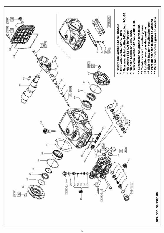
Transcript of I ISTRUZIONI D USO BEDIENUNGSANLEITUNG GB...

E3INTERPUMPGROUP
0.65219.54.125.610002175151503.8314.5E3A1515
0.65219.54.045.514501450101005.5521E3B1021
21
21
21
21
21
21
21
21
21
21
21
21
Ibs
0.659.56.188.414503625252503.4313E3B2513
0.659.58.4611.514503045212105.5521E3B2121
0.659.54.125.614501750121204.7618E3B1218
0.659.57.219.814503045212104.7618E3B2118
0.659.57.139.714503625252503.9615E3B2515
0.659.55.227.114503625252502.9111E3B2511
0.659.53.975.414502755191902.9111E3B1911
0.659.55.817.910003045212103.8314.5E3A2115
0.659.55.227.110003045212103.4313.0E3A2113
0.659.54.195.710002465171703.4313.0E3A1713
1450
kW Lt.
1450
0.659.54.265.82175151503.9615E3B1515
0.65
Kg
4.195.7
Hp
Potenza
Power
Puissance
Leistung
Potencia
Poder
9.5
psiMPabargpmL/min
2465171703.4313E3B1713
Peso
Weight
Poids
Gewicht
Peso
Peso
g/m
rpm
t/m
upm
r/m
r/m
Pressione
Pressure
Pression
Druck
Presión
Pressão
Portata
Flow rate
Débit
Förderstrom
Caudal
Fluxo
Modello
Model
Modèle
Modell
Modelo
ModeloS
E
R
I
E
S
59
D
E
P
I
GB
F
ISTRUZIONI D�USO
INSTRUCTIONS FOR USE
MODE D�EMPLOI
BEDIENUNGSANLEITUNG
INSTRUCCIONES DE USO
INSTRUÇÕES DE USO
Questo manuale deve essere letto e compreso in accordo al libretto generico �Istruzioni d�uso e manutenzione�.
This manual must be read and followed in accordance with the generic �Instructions for Use and Maintenance� booklet.
Ce manuel doit être lu et compris en accord avec la notice générale � Mode d�emploi et d�entretien �.
Dieses Handbuch ist in Verbindung mit dem allgemeinen Handbuch � Gebrauchs- und Wartungsanleitung� zu lesen und zu verstehen.
Este manual debe leerse y comprenderse de acuerdo con el manual general �Instrucciones de uso y mantenimiento�
Este manual deve ser lido e interpretado de acordo com o livro genérico �Instruções de uso e manutenção�

0.65219.58.0911.034003625252504.4917E3E2517
0.65219.57.8710.73400400027.52753.9615E3E2815
0.65219.58.6011.717503625252504.7618E3C2518
0.65219.56.188.417503625252503.4313E3C2513
0.65219.54.045.517501450101005.5521E3C1021
0.65219.54.265.817502175151503.9615E3C1515
0.65219.59.5613.034003625252505.2820E3E2520
0.65219.56.849.33400400027.52753.4313E3E2813
21
21
21
21
Ibs
0.659.510.0013.617503625252505.5521E3C2521
0.659.57.139.717503625252503.9615E3C2515
0.659.54.125.617501750121204.7618E3C1218
0.659.54.195.717502465171703.4313E3C1713
kW Lt.KgHp
Potenza
Power
Puissance
Leistung
Potencia
Poder
psiMPabargpmL/min
Peso
Weight
Poids
Gewicht
Peso
Peso
g/m
rpm
t/m
upm
r/m
r/m
Pressione
Pressure
Pression
Druck
Presión
Pressão
Portata
Flow rate
Débit
Förderstrom
Caudal
Fluxo
Modello
Model
Modèle
Modell
Modelo
Modelo
S
E
R
I
E
S
59
1

2

DIS
. C
OD
. 5
9.9
50
0.0
0
* F
issa
re c
on
Lo
cti
te5
42
co
l. R
OS
SO
* A
ffix
wit
h L
octi
te5
42
co
l. R
ED
* F
ixer a
vec d
e l
a L
octi
te5
42
co
ule
ur R
OU
GE
* M
itLo
cti
te5
42
RO
T b
efe
sti
ge
n
* F
ija
r co
n L
octi
te 5
42
co
l. R
OJO
* F
ixa
r c
om
Lo
cti
te 5
42
co
r.
VE
RM
ELH
A
**
Lu
bri
fica
re c
on
gra
sso
di v
aseli
na
**
To
lu
bri
ca
te w
ith
va
seli
ne g
rea
se
**
Lu
bri
fie
r a
ve
c g
ra
s d
es v
ase
lin
e
**
Sic
h m
it f
ett
zu
m v
aseli
nsch
mie
re
n
**
Pa
ra
lu
bri
ca
r c
on
la
gra
sa
de v
ase
lin
a
**
Pa
ra
lu
bri
fica
r co
m a
gra
xa
de v
ase
lin
a
3

KIT
29
0
23
�2
4
25
�2
6
27
�2
9
30 1
PIS
T.
Ø2
0
KIT
28
5
23
�2
4
25
�2
7
29 3
KIT
28
9
23
�2
4
25
�2
6
27
�2
9
30 1
PIS
T.
Ø1
8
KIT
28
4
23
�2
4
25
�2
7
29 3
PIS
T.
Ø2
2
KIT
28
6
23
�2
4
25
�2
7
29 3
KIT
29
1K
IT
27
1K
IT
27
0K
IT
26
9K
IT
Nr.
39 3
23
�2
4
25
�2
6
27
�2
9
30 1
8 �
9
20
-2
1
3 +
3
2 �
3 �
4
5 �
6 -
13
14
�1
5 -
16
17
�(7
) -
(1
8)
3 +
3
KIT
RIC
AM
BI �
SP
AR
E K
IT
S
Po
siz
ion
i
inclu
se
Po
sit
ion
s
inclu
de
d
Nr.
Pcs.
E3
A1
71
3 �
E3
A1
51
5 -
E3
B1
91
1 �
E3
B1
71
3
E3
B1
51
5 �
E3
B1
21
8 -
E3
B1
02
1 �
E3
C1
71
3
E3
C1
51
5 -
E3
C1
21
8 �
E3
C1
02
1
8Vite M
8x60 U
NI
5931
99.3
175.0
022
3Tappo M
18x1.5
x10 D
.23-D
.12
270
98.2
137.0
021
3O
R D
.15.6
0x1.7
8 N
BR 7
0 S
H 2
062 2
70
90.3
593.0
020
1Tappo G
1/8�x
898.1
966.0
019
3G
ruppo v
alv
ola
di m
andata
269
36.7
193.0
118
3G
uid
a v
alv
ola
di m
andata
269
36.2
111.5
117
3M
olla D
m.6
.2x10.4
269
94.7
333.0
016
3Valv
ola
sfe
rica
2
69
36.2
112.7
615
3Sede v
alv
ola
di m
andata
269
36.2
113.6
614
3Sede v
alv
ola
d�a
spirazio
ne
2
69
36.2
003.6
65
3O
R D
. 17.1
3x2.6
2 N
BR
70 S
H 3
068
269
90.3
841.0
06
3O
R D
.20.2
4x2.6
2 N
BR 7
0 S
H 3
081 2
70
90.3
847.0
08
3Tappo M
24x1.5
x16.7
270
98.2
226.0
09
3Vite M
5x55
99.1
690.0
010
3Rosett
a D
.5x11.5
x0.4
96.6
905.0
011
1 1 1
Pis
tone D
.18x42
Pis
tone D
.20x42
Pis
tone D
.22x42
58.0
402.0
9
59.0
400.0
9
59.0
401.0
9
12
3O
R D
.12.4
2x1.7
8 N
BR 7
0 S
H 2
050 2
69
90.3
589.0
013
3G
ruppo v
alv
ola
d�a
spirazio
ne
269
36.7
115.0
17
3Valv
ola
sfe
rica
2
69
36.2
001.7
64
DESCR
IZIO
NE �
DESCRIP
TIO
N -
KIT
Testa
ta p
om
pa D
.18
Testa
ta p
om
pa D
.20
Testa
ta p
om
pa D
.22
Guid
a v
alv
ola
d�a
spirazio
ne
2
69
Molla D
m. 9.4
x14.8
269
NR 1 1 1 3 3
CO
D.
59.1
202.4
1
59.1
203.4
1
59.1
204.4
1
36.2
025.5
1
94.7
676.0
0
PO
S
1 2 3
3Spin
ott
o D
.14x34
97.7
399.0
041
3G
uid
a p
isto
ne
59.0
50066
40
3Anello r
ad.
D.1
5x24x5/7
2
71
90.1
565.5
039
1Pro
tezio
ne
58.2
104.5
138
1Cart
er
pom
pa
59.0
100.2
237
1G
uarn
izio
ne s
pugna D
.3x103
59.2
110.8
236
3Rosett
a D
.7.5
x23x0.5
96.6
990.0
035
1Rosett
a D
.21.5
x27x1.5
96.7
514.0
034
1Tappo G
1/2�x
10
98.2
176.0
033
1Rosett
a D
.17.5
x23x1.5
96.7
380.0
032
3 3 3
Anello d
i te
sta
D.2
0
285-2
90
Anello d
i te
sta
D.2
2
286-2
91
Anello d
i te
sta
D.1
8
284-2
89
66.1
007.5
1
66.1
009.5
1
63.1
010.5
1
23
3 3 3
An.
ten.a
lt.
D.2
0x30x6/3
.7 H
P 2
85-2
90
An.
ten.a
lt.
D.2
2x32x6/3
.7 H
P 2
86-2
91
An.
ten.a
lt.
D.1
8x28x46/3
.7 H
P
284-2
89
90.2
691.0
0
90.2
716.0
0
90.2
653.5
0
24
3 3 3
Anello p
er
tenuta
D.1
8
289
Anello p
er
tenuta
D.2
0
290
Anello p
er
tenuta
D.2
2
291
59.2
107.7
0
59.2
108.7
0
59.2
109.7
0
30
1Tappo G
3/8�x
13
98.2
100.0
031
3O
R D
.31.4
7x1.7
8 N
BR 7
0 S
H.
2125
282-2
83-2
84-2
85-2
86-2
87-2
88-2
89-2
90-2
91
90.3
612.0
027
3 3 3
Anello t
en.
alt.
D.2
0x28x6.5
LP 2
85-2
90
Anello t
en.
alt.
D.2
2x30x6.5
LP 2
86-2
91
Anello t
en.
alt.
D.1
8x24x5 L
P
284-2
89
90.2
690.0
0
90.2
715.0
0
90.2
650.0
0
29
3 3 3
Anello a
ntiest.
D.1
8x28x2
284-2
89
Anello a
ntiest.
D.2
0x30x2
285-2
90
Anello a
ntiest.
D.2
2x32x2
286-2
91
90.5
111.5
0
90.5
134.0
0
90.5
148.5
0
25
3 3 3
Gr.
supp.
guarn
./bussola
D.1
8
289
Gr.
supp.
guarn
./bussola
D.2
0
290
Gr.
supp.
guarn
./bussola
D.2
2
291
59.6
060.0
1
59.6
061.0
1
59.6
062.0
1
26
NR
DESCR
IZIO
NE �
DESCRIP
TIO
N -
KIT
CO
D.
PO
S
2Pie
din
o p
om
pa
50.2
000.7
463
4Rosett
a D
. 8.4
UN
I 1751
96.7
016.0
062
4Vite M
8x16 U
NI
5739
99.3
037.0
061
1Lin
guett
a 8
x7x35
91.4
892.0
060
1Anello r
ad.
D.3
0x55x7
90.1
648.0
059
1Coperc
hio
late
rale
lato
PTO
47.1
510.2
258
1O
R D
.10.8
2x1.7
8 N
BR 7
0 S
H.
2043
90.3
585.0
057
1Tappo G
1/4�x
9 T
E17 �
Zin
c.
98.2
042.5
056
6Vite s
err
aggio
bie
lla M
8x35
99.3
099.0
043
3Bie
lla c
om
ple
ta59.0
300.0
142
1O
R D
.39.3
4x2.6
2 N
BR 7
0 S
H.
3156
90.3
877.0
045
1Coperc
hio
late
rale
lato
spia
47.1
512.2
244
1Coperc
hio
poste
riore
cart
er
59.1
600.2
255
1O
R D
.133.0
2x2.6
2 N
BR 7
0 S
H. 3525
90.3
922.0
054
1 1 1
Alb
ero
-E3A1515-E
3B1021-E
3C1021
Alb
ero
-E3A1713-E
3B1218-E
3B1515-E
3C1218
Alb
ero
-E3B1911-E
3C1713-E
3B1713-E
3C1515
59.0
201.3
5
59.0
202.3
5
59.0
203.3
5
47
1Spia
liv
ello o
lio
70.2
118.0
146
1Anello s
eeger
D.4
590.0
756.0
048
2Cuscin
ett
o a
rulli 30x62x21.2
591.8
375.0
050
12
Vite M
8x16 U
NI
5931
99.3
039.0
049
DESCR
IZIO
NE �
DESCRIP
TIO
N -
KIT
OR D
.67.9
5x2.6
2 N
BR 7
0 S
H.
3628
Spessore
D.7
4.5
x104x0.3
Spessore
D.7
4.5
x104x0.1
Asta
liv
ello o
lio G
3/8�x
51 D
.7
1 1
97.5
680.0
0
97.5
978.0
052
198.2
105.0
053
NR 2
CO
D.
90.3
913.0
0
PO
S
51
PIS
TO
N Ø
20
E3
B1
71
3
E3
B1
51
5
E3
C1
51
5
E3
C1
21
8
E3
C1
02
1
PIS
TO
N Ø
18
E3
B1
91
1
E3
C1
71
3
PIS
TO
N Ø
22
E3
A1
71
3
E3
A1
51
5
E3
B1
21
8
E3
B1
02
1
4
DIS
. C
OD
. 5
9.9
50
0.0
0
* F
issa
re c
on
Lo
cti
te5
42
co
l. R
OS
SO
* A
ffix
wit
h L
octi
te5
42
co
l. R
ED
* F
ixer a
vec d
e l
a L
octi
te5
42
co
ule
ur R
OU
GE
* M
itLo
cti
te5
42
RO
T b
efe
sti
ge
n
* F
ija
r co
n L
octi
te 5
42
co
l. R
OJO
* F
ixa
r c
om
Lo
cti
te 5
42
co
r.
VE
RM
ELH
A
**
Lu
bri
fica
re c
on
gra
sso
di v
aseli
na
**
To
lu
bri
ca
te w
ith
va
seli
ne g
rea
se
**
Lu
bri
fie
r a
ve
c g
ra
s d
es v
ase
lin
e
**
Sic
h m
it f
ett
zu
m v
aseli
nsch
mie
re
n
**
Pa
ra
lu
bri
ca
r c
on
la
gra
sa
de v
ase
lin
a
**
Pa
ra
lu
bri
fica
r co
m a
gra
xa
de v
ase
lin
a
5

KIT
29
0
23
�2
4
25
�2
6
27
�2
9
30 1
PIS
T.
Ø2
0
KIT
28
5
23
�2
4
25
�2
7
29 3
KIT
28
9
23
�2
4
25
�2
6
27
�2
9
30 1
PIS
T.
Ø1
8
KIT
28
4
23
�2
4
25
�2
7
29 3
PIS
T.
Ø1
5P
IS
T.
Ø2
2P
IS
T.
Ø1
3
KIT
28
3
23
�2
4
25
�2
7
29 3
KIT
28
8
23
�2
4
25
�2
6
27
�2
9
30 1
KIT
28
7
23
�2
4
25
�2
6
27
�2
9
30 1
KIT
28
6
23
�2
4
25
�2
7
29 3
KIT
28
2
23
�2
4
25
�2
7
29 3
KIT
29
1K
IT
27
1K
IT
29
2K
IT
26
9K
IT
Nr.
39 3
23
�2
4
25
�2
6
27
�2
9
30 1
8 �
9
20
-2
1
3 +
3
2 �
3 �
4
5 �
6 -
13
14
�1
5 �
16
17
-(7
) -
(1
8)
3 +
3
KIT
RIC
AM
BI �
SP
AR
E K
IT
S
Po
siz
ion
i
inclu
se
Po
sit
ion
s
inclu
de
d
Nr.
Pcs.
E3
A2
11
3 �
E3
A2
11
5 -
E3
B2
51
1 �
E3
B2
51
3
E3
B2
51
5 -
E3
B2
11
8 �
E3
B2
12
1 �
E3
C2
51
3
E3
C2
51
5 -
E3
C2
51
8 �
E3
C2
52
1 �
E3
E2
81
3
E3
E2
81
5 -
E3
E2
51
7 �
E3
E2
52
0
3Tappo M
18x1.5
x10 D
.23-D
.12 �
NK 2
92
98.2
137.5
021
3O
R D
.15.6
0x1.7
8 N
BR 7
0 S
H 2
062 2
92
90.3
593.0
020
1Tappo G
1/8�x
8 -
NIC
KEL
98.1
967.0
019
3G
ruppo v
alv
ola
di m
andata
269
36.7
193.0
118
3G
uid
a v
alv
ola
di m
andata
269
36.2
111.5
117
3M
olla D
m.6
.2x10.4
269
94.7
333.0
016
3Valv
ola
sfe
rica
2
69
36.2
112.7
615
3Sede v
alv
ola
di m
andata
269
36.2
113.6
614
3Sede v
alv
ola
d�a
spirazio
ne
2
69
36.2
003.6
65
3O
R D
. 17.1
3x2.6
2 N
BR
70 S
H 3
068
269
90.3
841.0
06
3O
R D
.20.2
4x2.6
2 N
BR 7
0 S
H 3
081 2
92
90.3
847.0
08
3Tappo M
24x1.5
x16.7
�N
ICKEL
292
98.2
225.0
09
3Vite M
5x55
99.1
690.0
010
3Rosett
a D
.5x11.5
x0.4
96.6
905.0
011
1 1 1 1 1
Pis
tone D
.13x42
Pis
tone D
.15x42
Pis
tone D
.18x42
Pis
tone D
.20x42
Pis
tone D
.22x42
58.0
400.0
9
58.0
401.0
9
58.0
402.0
9
59.0
400.0
9
59.0
401.0
9
12
3O
R D
.12.4
2x1.7
8 N
BR 7
0 S
H 2
050 2
69
90.3
589.0
013
3G
ruppo v
alv
ola
d�a
spirazio
ne
269
36.7
115.0
17
3Valv
ola
sfe
rica
2
69
36.2
001.7
64
DESCR
IZIO
NE �
DESCRIP
TIO
N -
KIT
Testa
ta p
om
pa D
.13 -
NIC
KEL
Testa
ta p
om
pa D
.15 -
NIC
KEL
Testa
ta p
om
pa D
.18 -
NIC
KEL
Testa
ta p
om
pa D
.20 -
NIC
KEL
Testa
ta p
om
pa D
.22 -
NIC
KEL
Guid
a v
alv
ola
d�a
spirazio
ne
2
69
Molla D
m. 9.4
x14.8
269
NR 1 1 1 1 1 3 3
CO
D.
59.1
210.4
1
59.1
211.4
1
59.1
212.4
1
59.1
213.4
1
59.1
214.4
1
36.2
025.5
1
94.7
676.0
0
PO
S
1 2 3
3Rosett
a D
.7.5
x23x0.5
96.6
990.0
035
1Rosett
a D
.21.5
x27x1.5
96.7
514.0
034
1Tappo G
1/2�x
10 -
NIC
KEL
98.2
179.0
033
3 3 3 3 3
Anello d
i te
sta
D.2
0
285-2
90
Anello d
i te
sta
D.2
2
286-2
91
Anello d
i te
sta
D.1
5
283-2
88
Anello d
i te
sta
D.1
8
284-2
89
Anello d
i te
sta
D.1
3
282-2
87
66.1
007.5
1
66.1
009.5
1
63.1
010.5
1
63.1
011.5
1
44.1
002.5
1
23
1Rosett
a D
.17.5
x23x1.5
96.7
380.0
032
8Vite M
8x60 U
NI
5931
99.3
175.0
022
3 3 3 3 3
An.
ten.a
lt.
D.2
0x30x6/3
.7 H
P 2
85-2
90
An.
ten.a
lt.
D.2
2x32x6/3
.7 H
P 2
86-2
91
An.
ten.a
lt.
D.1
5x24x5.4
/3.4
HP 2
83-2
88
An.
ten.a
lt.
D.1
8x28x46/3
.7 H
P
284-2
89
An.
ten.a
lt.
D.1
3x21x4 H
P
2
82-2
87
90.2
691.0
0
90.2
716.0
0
90.2
611.0
0
90.2
653.5
0
90.2
602.0
0
24
3 3 3 3 3
Anello p
er
tenuta
D.1
3
287
Anello p
er
tenuta
D.1
5
288
Anello p
er
tenuta
D.1
8
289
Anello p
er
tenuta
D.2
0
290
Anello p
er
tenuta
D.2
2
291
59.2
105.7
0
59.2
106.7
0
59.2
107.7
0
59.2
108.7
0
59.2
109.7
0
30
1Tappo G
3/8�x
13 -
NIC
KEL
98.2
099.0
031
3O
R D
.31.4
7x1.7
8 N
BR 7
0 S
H.
2125
282-2
83-2
84-2
85-2
86-2
87-2
88-2
89-2
90-2
91
90.3
612.0
027
3 3 3 3 3
Anello t
en.
alt.
D.2
0x28x6.5
LP 2
85-2
90
Anello t
en.
alt.
D.2
2x30x6.5
LP 2
86-2
91
Anello t
en.
alt.
D.1
5x22x5 L
P
283-2
88
Anello t
en.
alt.
D.1
8x24x5 L
P
284-2
89
Anello t
en.
alt.
D.1
3x20x5 L
P
282-2
87
90.2
690.0
0
90.2
715.0
0
90.2
608.0
0
90.2
650.0
0
90.2
601.0
0
29
3 3 3 3 3
Anello a
ntiest.
D.1
3x21x4
282-2
87
Anello a
ntiest.
D.1
5x24x2
283-2
88
Anello a
ntiest.
D.1
8x28x2
284-2
89
Anello a
ntiest.
D.2
0x30x2
285-2
90
Anello a
ntiest.
D.2
2x32x2
286-2
91
90.5
076.5
0
90.5
089.9
0
90.5
111.5
0
90.5
134.0
0
90.5
148.5
0
25
3 3 3 3 3
Gr.
suup.
guarn
./boccola
D.1
3
287
Gr.
suup.
guarn
./boccola
D.1
5
288
Gr.
suup.
guarn
./boccola
D.1
8
289
Gr.
suup.
guarn
./boccola
D.2
0
290
Gr.
suup.
guarn
./boccola
D.2
2
291
59.6
058.0
1
59.6
059.0
1
59.6
060.0
1
59.6
061.0
1
59.6
062.0
1
26
NR
DESCR
IZIO
NE �
DESCRIP
TIO
N -
KIT
CO
D.
PO
S
2Pie
din
o p
om
pa
50.2
000.7
463
4Rosett
a D
. 8.4
UN
I 1751
96.7
016.0
062
4Vite M
8x16 U
NI
5739
99.3
037.0
061
1Lin
guett
a 8
x7x35
91.4
892.0
060
1Anello r
ad.
D.3
0x55x7
90.1
648.0
059
1Coperc
hio
late
rale
lato
PTO
47.1
510.2
258
1O
R D
.10.8
2x1.7
8 N
BR 7
0 S
H.
2043
90.3
585.0
057
1Tappo G
1/4�x
9 T
E17 �
Zin
c.
98.2
042.5
056
1G
uarn
izio
ne s
pugna D
.3x103
59.2
110.8
236
1Cart
er
pom
pa
59.0
100.2
237
1Pro
tezio
ne
58.2
104.5
138
6Vite s
err
aggio
bie
lla M
8x35
99.3
099.0
043
3Bie
lla c
om
ple
ta59.0
300.0
142
3Spin
ott
o D
.14x34
97.7
399.0
041
3G
uid
a p
isto
ne
59.0
50066
40
1O
R D
.39.3
4x2.6
2 N
BR 7
0 S
H.
3156
90.3
877.0
045
1Coperc
hio
late
rale
lato
spia
47.1
512.2
244
3Anello r
ad.
D.1
5x24x5/7
271
90.1
565.5
039
1Coperc
hio
poste
riore
cart
er
59.1
600.2
255
1O
R D
.133.0
2x2.6
2 N
BR 7
0 S
H. 3525
90.3
922.0
054
1 1 1
Alb
ero
�E3A2115-E
3B2121-E
3C2521-E
3E2815
Alb
ero
�E3A2113-E
3B2118-E
3B2515-E
3C2518
E3E2520
Alb
ero
�E3B2511-E
3B2513-E
3C2513-E
3C2515
E3E2813-E
3E2517
59.0
201.3
5
59.0
202.3
5
59.0
203.3
5
47
1Spia
liv
ello o
lio
70.2
118.0
146
1Anello s
eeger
D.4
590.0
756.0
048
2Cuscin
ett
o a
rulli 30x62x21.2
591.8
375.0
050
12
Vite M
8x16 U
NI
5931
99.3
039.0
049
DESCR
IZIO
NE �
DESCRIP
TIO
N -
KIT
OR D
.67.9
5x2.6
2 N
BR 7
0 S
H.
3628
Spessore
D.7
4.5
x104x0.3
Spessore
D.7
4.5
x104x0.1
Asta
liv
ello o
lio G
3/8�x
51 D
.7
1 1
97.5
680.0
0
97.5
978.0
052
198.2
105.0
053
NR 2
CO
D.
90.3
913.0
0
PO
S
51
PIS
TO
N Ø
20
E3
B2
51
3
E3
B2
51
5
E3
C2
51
5
E3
C2
51
8
E3
C2
52
1
PIS
TO
N Ø
18
E3
C2
51
1
E3
C2
51
3
PIS
TO
N Ø
22
E3
A2
11
3
E3
A2
11
5
E3
B2
11
8
E3
B2
12
1
PIS
TO
N Ø
15
E3
E2
51
7
E3
E2
52
0
PIS
TO
N Ø
13
E3
E2
81
3
E3
E2
81
5
6

DIS
. C
OD
. 5
9.9
50
1.0
0
**
Lu
bri
fica
re c
on
gra
sso
di v
aseli
na
**
To
lu
bri
ca
te w
ith
va
seli
ne g
rea
se
**
Lu
bri
fie
r a
ve
c g
ra
s d
es v
ase
lin
e
**
Sic
h m
it f
ett
zu
m v
aseli
nsch
mie
re
n
**
Pa
ra
lu
bri
ca
r c
on
la
gra
sa
de v
ase
lin
a
**
Pa
ra
lu
bri
fica
r co
m a
gra
xa
de v
ase
lin
a
* F
issa
re c
on
Lo
cti
te5
42
co
l. R
OS
SO
* A
ffix
wit
h L
octi
te5
42
co
l. R
ED
* F
ixer a
vec d
e l
a L
octi
te5
42
co
ule
ur R
OU
GE
* M
itLo
cti
te5
42
RO
T b
efe
sti
ge
n
* F
ija
r co
n L
octi
te 5
42
co
l. R
OJO
* F
ixa
r c
om
Lo
cti
te 5
42
co
r.
VE
RM
ELH
A
7

PIS
T.
Ø1
5P
IS
T.
Ø1
3
KIT
28
3
23
�2
4
25
�2
7
29 3
KIT
28
8
23
�2
4
25
�2
6
27
�2
9
30 1
KIT
28
7
23
�2
4
25
�2
6
27
�2
9
30 1
KIT
28
2
23
�2
4
25
�2
7
29 3
KIT
27
1K
IT
29
2K
IT
26
9K
IT
Nr.
39 3
8 �
9
20
-2
1
3 +
3
2 �
3 �
4
5 �
6 -
13
14
�1
5 �
16
17
�(7
) -
(1
8)
3 +
3
KIT
RIC
AM
BI �
SP
AR
E K
IT
S
Po
siz
ion
i
inclu
se
Po
sit
ion
s
inclu
de
d
Nr.
Pcs.
E3
E2
81
3 �
E3
E2
81
5
E3
E2
51
7 �
E3
E2
52
0
8Vite M
8x60 U
NI
5931
99.3
175.0
022
3Tappo M
18x1.5
x10 D
.23-D
.12�
NK 2
92
98.2
137.5
021
3O
R D
.15.6
0x1.7
8 N
BR 7
0 S
H 2
062 2
92
90.3
593.0
020
1Tappo G
1/8�x
8 -
NIC
KEL
98.1
967.0
019
3G
ruppo v
alv
ola
di m
andata
269
36.7
193.0
118
3G
uid
a v
alv
ola
di m
andata
269
36.2
111.5
117
3 3
Anello d
i te
sta
D.1
5
283-2
88
Anello d
i te
sta
D.1
3
282-2
87
63.1
010.5
1
44.1
002.5
123
3M
olla D
m.6
.2x10.4
269
94.7
333.0
016
3Valv
ola
sfe
rica
2
69
36.2
112.7
615
3Sede v
alv
ola
di m
andata
269
36.2
113.6
614
3Sede v
alv
ola
d�a
spirazio
ne
2
69
36.2
003.6
65
3O
R D
. 17.1
3x2.6
2 N
BR
70 S
H 3
068
269
90.3
841.0
06
3O
R D
.20.2
4x2.6
2 N
BR 7
0 S
H 3
081 2
92
90.3
847.0
08
3Tappo M
24x1.5
x16.7
�N
ICKEL
2
92
98.2
225.0
09
3Vite M
5x55
99.1
690.0
010
3Rosett
a D
.5x11.5
x0.4
96.6
905.0
011
1 1
Pis
tone D
.13x42
Pis
tone D
.15x42
58.0
400.0
9
58.0
401.0
912
3O
R D
.12.4
2x1.7
8 N
BR 7
0 S
H 2
050 2
69
90.3
589.0
013
3G
ruppo v
alv
ola
d�a
spirazio
ne
269
36.7
115.0
17
3Valv
ola
sfe
rica
2
69
36.2
001.7
64
DESCR
IZIO
NE �
DESCRIP
TIO
N -
KIT
Testa
ta p
om
pa D
.13 -
NIC
KEL
Testa
ta p
om
pa D
.15 -
NIC
KEL
Guid
a v
alv
ola
d�a
spirazio
ne
2
69
Molla D
m. 9.4
x14.8
269
NR 1 1 3 3
CO
D.
59.1
210.4
1
59.1
211.4
1
36.2
025.5
1
94.7
676.0
0
PO
S
1 2 3
1O
R D
.55.5
6x3.5
3 N
BR 7
0 S
H.
159
90.4
097.0
047
1Anello s
eeger
D.6
290.0
850.0
045
1Coperc
hio
late
rale
lato
spia
47.1
500.2
244
2O
R D
.67.9
5x2.6
2 N
BR 7
0 S
H.
3628
90.3
913.0
046
6Vite s
err
aggio
bie
lla M
8x35
99.3
099.0
043
3Bie
lla c
om
ple
ta59.0
300.0
142
3Spin
ott
o D
.14x34
97.7
399.0
041
3G
uid
a p
isto
ne
59.0
500.6
640
3Anello r
ad.
D.1
5x24x5/7
2
71
90.1
565.5
039
1Pro
tezio
ne
58.2
104.5
138
1Cart
er
pom
pa
59.0
100.2
237
1G
uarn
izio
ne s
pugna D
.3x103
59.2
110.8
236
3Rosett
a D
.7.5
x23x0.5
96.6
990.0
035
1Rosett
a D
.21.5
x27x1.5
96.7
514.0
034
1Tappo G
1/2�x
10 -
NIC
KEL
98.2
179.0
033
1Rosett
a D
.17.5
x23x1.5
96.7
380.0
032
3 3
An.
ten.a
lt.
D.1
5x24x5.4
/3.4
HP 2
83-2
88
An.
ten.a
lt.
D.1
3x21x4 H
P
2
82-2
87
90.2
611.0
0
90.2
602.0
024
3 3
Anello p
er
tenuta
D.1
3
287
Anello p
er
tenuta
D.1
5
288
59.2
105.7
0
59.2
106.7
030
1Tappo G
3/8�x
13 -
NIC
KEL
98.2
099.0
031
3O
R D
.31.4
7x1.7
8 N
BR 7
0 S
H.
2125
282-2
83-2
84-2
85-2
86-2
87-2
88-2
89-2
90-2
91
90.3
612.0
027
3 3
Anello t
en.
alt.
D.1
5x22x5 L
P
283-2
88
Anello t
en.
alt.
D.1
3x20x5 L
P
282-2
87
90.2
608.0
0
90.2
601.0
029
3 3
Anello a
ntiest.
D.1
3x21x4
282-2
87
Anello a
ntiest.
D.1
5x24x2
283-2
88
90.5
076.5
0
90.5
089.9
025
3 3
Gr.
supp.
guarn
/./b
ussola
D.1
3
287
Gr.
supp.
guarn
/./b
ussola
D.1
5
288
59.6
058.0
1
59.6
059.0
126
NR
DESCR
IZIO
NE �
DESCRIP
TIO
N -
KIT
CO
D.
PO
S
1Vite M
6x6 U
NI
5929
99.1
790.0
061
1Fla
ngia
moto
re a
scoppio
C1�
10.0
801.2
260
1Coperc
hio
ante
riore
cart
er
66.1
502.7
453
4Rosett
a D
.10.5
x16x1
96.7
104.0
066
4Vite 3
/8�-
16x1-1
/4�
99.3
346.0
065
4Vite M
8x30 U
NI
5931
90.3
084.0
064
1Boccola
a r
ullin
i D
.50x58x25
91.8
585.0
063
1Anello r
ad.
D.4
5x62x8
90.1
690.0
062
4Vite M
8x16 U
NI
5931
99.3
039.0
059
1O
R D
.10.8
2x1.7
8 N
BR 7
0 S
H.
2043
90.3
585.0
058
1Tappo G
1/4�x
9 T
E17 �
Zin
c.
98.2
042.5
057
1Coperc
hio
poste
riore
cart
er
59.1
600.2
256
1O
R D
.133.0
2x2362 N
BR 7
0 S
H.
3525
90.3
922.0
055
1 1 1
Alb
ero
�E3E2815
Alb
ero
�E3E2520
Alb
ero
�E3E2517-E
3E2813
59.0
204.6
5
59.0
205.6
5
59.0
206.6
5
49
1D
ista
nzia
le c
on indic
ato
re44.2
118.0
148
1Anello s
eeger
D.3
090.0
66700
50
1Cuscin
ett
o a
rulli
91.8
376.0
052
4Vite M
8x25 U
NI
5931
99.3
069.0
051
DESCR
IZIO
NE �
DESCRIP
TIO
N -
KIT
Asta
liv
ello o
lio G
3/8�x
51 D
.71
98.2
105.0
054
NR
CO
D.
PO
S
PIS
TO
N Ø
15
E3
E2
51
7 -
E3
E2
52
0
PIS
TO
N Ø
13
E3
E2
81
3 -
E3
E2
81
5
8

VH VERSION
VERSIONE CON VALVOLA DI REGOLAZIONE AUT. � VERSION WITH BUILT-IN AUT. UNLOADER
VERSION AVEC RÉGULATEUR AUT. DE PRESSION INCORPORÉ
AUSFÜHRUNG MIT EINGEBAUTEM AUT. DRUCKREGULIERVENTIL
VERSIÓN CON REGULADOR AUT. DE PRESIÓN INCORPORADO - VERSÃO COM VÁLVULA DO REGULAMENTO AUT.
DIS. COD. 36.9548.00
OPTIONALS
9

1OR Ø 10.82x1.78 NBR 70 Sh. 2043
279-28090.3585.0028
1Tappo G 1/4�x998.2041.0029
1
Nipplo 3/8� NPT � F � Ø3
Nipplo G 3/8� � F � Ø3
Nipplo M22x1.5 � Ø3
Nipplo 3/8� NPT � M � Ø3
Nipplo G 3/8� � M � Ø3
36.3490.70
36.3489.70
36.3488.70
36.3487.70
36.3479.70
27
1OR Ø 15.88x2.62 NBR 70 Sh. 121 27890.3839.0026
1Guida valvola 27836.3104.5125
1Molla Ø 8.5x12 27894.7355.0024
1Sfera Ø 13/32� 27897.4838.0023
1OR D.9.92x2.62 NBR 70 SH. 112 27890.3823.0022
1Sede36.3483.6621
1OR D.7.66x1.78 NBR 70 SH. 203190.3578.0020
1Anello antiest. D.9x12x1.590.5038.0019
1OR D.8.73x1.78 NBR 70 SH. 10890.3581.0018
1OR D.11.11x1.78 NBR 70 SH. 11490.3587.0017
1Boccola di guidaN.A.16
1Ghiera di pressione massima36.3477.7015
1Vite M4x5 UNI 592999.1267.0014
1OtturatoreN.A.13
1Anello antiest. D.4x7x1.5N.A.12
1OR D.3.69x1.78 NBR 70 Sh. 2015N.A.11
1OR D.6.07x1.78 NBR 70 Sh. 2025N.A.10
1Anello antiest. D.6.1x9x1.5N.A.9
1Pistoncino di comandoN.A.8
1Molla D.11.3x34.594.7395.006
2Rondella di scorrimento36.3486.515
1Registro di pressione36.3481.704
1OR D.18.72X2.62 NBR 70 SH. 307590.3845.003
1OR D.2.90X1.78 NBR 70 SH. 201290.3566.002
1Pomolo di regolazione36.3485.511
NRDESCRIZIONE � DESCRIPTION - KITCOD.POS
1Otturatore con portagomma 27936.3342.7042
1Spina elastica Ø 2x12 UNI 6873 27997.6615.0043
1OR Ø 17.13x2.62 NBR 70 Sh. 306890.3841.0030
1Nipplo aspirazione G 3/4�36.3182.5131
1Filtro Ø 12x3592.8925.0032
1OR Ø 12.37x2.62 NBR 70 Sh. 305090.3828.0033
1Portagomma aspirazione36.2569.5134
1Ghiera G 3/4� � Ø 1592.9828.0035
OPTIONALS
1Frutto valvola con sede 27836.6054.0147
1
Testata pompa con valv. integr. D.15
Testata pompa con valv. integr. D.18
Testata pompa con valv. integr. D.20
Testata pompa con valv. integr. D.22
59.1206.41
59.1207.41
59.1208.41
59.1209.41
46
1Portagomma 28036.3492.7045
1Pomolo detergente rosso 27936.3484.5144
1Molla Ø 6.4x12.5 27994.7334.0041
1Sede valvola detergente 27936.3482.7040
2OR Ø 5.28x1.78 NBR 70 Sh. 2021
279-28090.3573.0039
1Sfera Ø 7/32� 279-28097.4782.0038
1Molla conica Ø 4.3/7.3x11 279-28094.8217.0037
1Ugello per iniettore Ø 2
Ugello per iniettore Ø 2.2
10.0795.66
10.0798.6636
NRDESCRIZIONE � DESCRIPTION - KITCOD.POS
-
28 � 37
38 � 39
45
KIT 280
--Nr. Pcs.
KIT RICAMBI � SPARE KITS
28 � 37
38 � 39
40 � 41
42 � 43
44
22 � 23
24 � 25
26 - 47
Posizioni
incluse
Positions
included
KIT 279KIT 278KIT NR.
VH VERSION
VERSIONE CON VALVOLA DI REGOLAZIONE AUT. � VERSION WITH BUILT-IN AUT. UNLOADER
VERSION AVEC RÉGULATEUR AUT. DE PRESSION INCORPORÉ
AUSFÜHRUNG MIT EINGEBAUTEM AUT. DRUCKREGULIERVENTIL
VERSIÓN CON REGULADOR AUT. DE PRESIÓN INCORPORADO - VERSÃO COM VÁLVULA DO REGULAMENTO AUT.
N.A. : NOT AVAILABLE � PARTICOLARE NON FORNITO
10

COD. DIS. 59.9600.00
DIMENSIONI D�INGOMBRO � OVERALL DIMENSIONS � DIMENSIONS D�ENCOMBREMENT
RAUMBEDARF � DIMENSIONES TOTALES � DIMENSÕES
STANDARD
COD. DIS. 59.9602.00C 1�
11
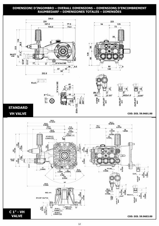
DIMENSIONI D�INGOMBRO � OVERALL DIMENSIONS � DIMENSIONS D�ENCOMBREMENT
RAUMBEDARF � DIMENSIONES TOTALES � DIMENSÕES
COD. DIS. 59.9601.00
STANDARD
VH VALVE
COD. DIS. 59.9603.00
C 1� - VH
VALVE
12

1 � OIL CHANGING
1 - CHANGEMENT DE L�HUILE
1.1 � Oil changing must be done with the pump at operating temperature.
1.2 � Put a container under the oil drain plug (3).
1.3 � Remove the oil dipstick (1) and then the drain plug (3).
1.4 � Wait until all the oil has drained out, then screw the drain plug (3) and tighten at the torque shown in
the exploded diagram.
1.5 � Fill with new oil until the middle of the oil level indicator (2) is reached, screw by hand the oil dipstick
(1).
Refer to the generic booklet for the type of oil to use.
WARNING: The exhaust oil must be collected in receptacles and disposed of at
authorised centres as specified by law. It must not be thrown away in the
environment.
1.1 � Le changement de l�huile doit être exécuté avec la pompe à température d�exercice.
1.2 � Placer un récipient sous le bouchon de vidange de l�huile (3).
1.3 � Enlever le bouchon-jauge (1), puis enlever le bouchon de vidange (3).
1.4 � Attendre que toute l�huile soit sortie, puis revisser le bouchon de vidange (3) avec le couple de
torsion qui est indiqué sur le dessin éclaté.
1.5 � Remplir avec de l�huile neuve jusqu�à la ligne médiane du bouchon indicateur du niveau d�huile (2), et
revisser le bouchon-jauge (1).
Pour le type d�huile à utiliser, se référer à ce qui est indiqué sur la notice générale.
ATTENTION : L�huile usée doit être recueillie dans des récipients et éliminée dans les
centres prévus à cet effet, conformément à la réglementation en vigueur. Il ne faut
absolument pas la jeter dans l�environnement.
1 - CAMBIO OLIO
1.1 � Il cambio dell�olio va eseguito con pompa a
temperatura di lavoro.
1.2 � Posizionare un recipiente sotto il tappo di scarico olio (3).
1.3 � Rimuovere il tappo con asta (1) e successivamente il
tappo di scarico (3).
1.5 � Riempire con olio nuovo fino al raggiungimento della
mezzeria del tappo spia livello olio (2) e riavvitare il tappo con
asta (1) .
1.4 � Attendere fino a quando tutto l�olio è uscito, quindi
riavvitare il tappo di scarico (3) con la coppia torcente indicata
su disegno esploso.
ATTENZIONE: L�olio esausto deve essere raccolto in recipienti e smaltito negli
appositi centri in accordo alla normativa vigente. Non deve essere assolutamente
disperso nell�ambiente.
1
32
Per il tipo di olio da utilizzare fare riferimento a quanto indicato sul libretto generico.
13
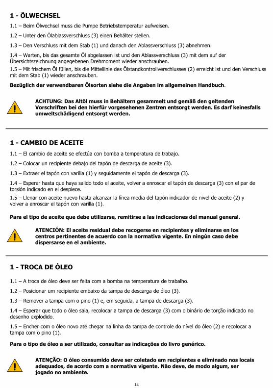
1.1 � El cambio de aceite se efectúa con bomba a temperatura de trabajo.
1.2 � Colocar un recipiente debajo del tapón de descarga de aceite (3).
1.3 � Extraer el tapón con varilla (1) y seguidamente el tapón de descarga (3).
1.4 � Esperar hasta que haya salido todo el aceite, volver a enroscar el tapón de descarga (3) con el par de
torsión indicado en el despiece.
1.5 � Llenar con aceite nuevo hasta alcanzar la línea media del tapón indicador de nivel de aceite (2) y
volver a enroscar el tapón con varilla (1).
Para el tipo de aceite que debe utilizarse, remitirse a las indicaciones del manual general.
ATENCIÓN: El aceite residual debe recogerse en recipientes y eliminarse en los
centros pertinentes de acuerdo con la normativa vigente. En ningún caso debe
dispersarse en el ambiente.
1.1 � A troca de óleo deve ser feita com a bomba na temperatura de trabalho.
1.2 � Posicionar um recipiente embaixo da tampa de descarga de óleo (3).
1.3 � Remover a tampa com o pino (1) e, em seguida, a tampa de descarga (3).
1.4 � Esperar que todo o óleo saia, recolocar a tampa de descarga (3) com o binário de torção indicado no
desenho explodido.
1.5 � Encher com o óleo novo até chegar na linha da tampa de controle do nível do óleo (2) e recolocar a
tampa com o pino (1).
Para o tipo de óleo a ser utilizado, consultar as indicações do livro genérico.
ATENÇÃO: O óleo consumido deve ser coletado em recipientes e eliminado nos locais
adequados, de acordo com a normativa vigente. Não deve, de modo algum, ser
jogado no ambiente.
1 - CAMBIO DE ACEITE
1 - TROCA DE ÓLEO
1 - ÖLWECHSEL
1.1 � Beim Ölwechsel muss die Pumpe Betriebstemperatur aufweisen.
1.2 � Unter den Ölablassverschluss (3) einen Behälter stellen.
1.3 � Den Verschluss mit dem Stab (1) und danach den Ablassverschluss (3) abnehmen.
1.4 � Warten, bis das gesamte Öl abgelassen ist und den Ablassverschluss (3) mit dem auf der
Übersichtszeichnung angegebenen Drehmoment wieder anschrauben.
1.5 � Mit frischem Öl füllen, bis die Mittellinie des Ölstandkontrollverschlusses (2) erreicht ist und den Verschluss
mit dem Stab (1) wieder anschrauben.
Bezüglich der verwendbaren Ölsorten siehe die Angaben im allgemeinen Handbuch.
ACHTUNG: Das Altöl muss in Behältern gesammelt und gemäß den geltenden
Vorschriften bei den hierfür vorgesehenen Zentren entsorgt werden. Es darf keinesfalls
umweltschädigend entsorgt werden.
14

DICHIARAZIONE DI INCORPORAZIONE(Ai sensi dell�allegato II della Direttiva Europea 2006/42/CE).
Il produttore INTERPUMP GROUP S.p.A. � Via E. Fermi, 25 � 42049 S.ILARIO D�ENZA (RE) - Italia
DICHIARA sotto la propria esclusiva responsabilità che l�attrezzatura identificata e descritta come segue :
Denominazione: Pompa
Tipo: Pompa alternativa a pistoni per acqua ad alta pressione
Marchio di fabbrica: INTERPUMP GROUP
Modello: E3A1713 � E3A1515 � E3A2113 � E3A2115 - E3B1911 � E3B1713 � E3B1515 � E3B1218
E3B1021 � E3B2511 � E3B2513 � E3B2515 - E3B2118 E3B2121 � E3C1713 � E3C1515 - E3C1218
E3C1021 � E3C2513 � E3C2515 - E3C2518 � E3C2521 E3E2813 � E3E2815 - E3E2517 � E3E2520
Risulta essere conforme alle sotto elencate direttive e successivi aggiornamenti :
- Direttiva Macchine 2006/42/CE
- Direttiva sulla restrizione dell�uso di determinate sostanze pericolose nelle apparecchiature elettriche ed
elettroniche 2011/65/UE - RoHS
L�attrezzatura non contiene sostanze con restrizioni d�uso in concentrazione maggiore di quelle elencate
nell�allegato II ad eccezione delle applicazioni esentate dalle restrizioni elencate nell�allegato III.
Norme applicate : UNI EN ISO 12100:2010 - UNI EN 809:2000
Firma ________________
La pompa sopra identificata rispetta i seguenti requisiti essenziali di sicurezza e di tutela della salute elencati
nel punto 1 dell�allegato I della Direttiva Macchine :
1.1.2 - 1.1.3 - 1.1.5 - 1.3.1 - 1.3.2 - 1.3.3 - 1.3.4 - 1.5.4 - 1.5.5 - 1.6.1 - 1.7.1 - 1.7.2 - 1.7.4 - 1.7.4.1 - 1.7.4.2
e la relativa documentazione tecnica è stata compilata in conformità dell�allegato VII B.
Inoltre il produttore si impegna a rendere disponibile, a seguito di una richiesta adeguatamente motivata,
copia della documentazione tecnica pertinente la pompa nei modi e nei termini da definire.
La pompa non deve essere messa in servizio finché l�impianto al quale la pompa deve essere incorporata è
stato dichiarato conforme alle disposizioni delle relative direttive e/o norme.
Persona autorizzata a costituire il fascicolo tecnico : Nome: Maurizio Novelli
Persona autorizzata a redigere la dichiarazione : L�amministratore delegato Ing. Paolo Marinsek
Reggio Emilia 03/2013
Indirizzo: INTERPUMP GROUP S.p.A. � Via E. Fermi, 25 � 42049 S. ILARIO D�ENZA (RE) � Italia
15

DECLARATION OF INCORPORATION(In accordance with Annex II of European Directive 2006/42/CE).
The manufacturer INTERPUMP GROUP S.p.A. � Via E. Fermi, 25 � 42049 S.ILARIO D�ENZA (RE) - Italy
DECLARES under sole responsibility that the equipment identified and described as follows :
Name: Pump
Type: Reciprocating plunger pump for high pressure water
Trademark: INTERPUMP GROUP
Model: E3A1713 � E3A1515 � E3A2113 � E3A2115 - E3B1911 � E3B1713 � E3B1515 � E3B1218
E3B1021 � E3B2511 � E3B2513 � E3B2515 - E3B2118 E3B2121 � E3C1713 � E3C1515 - E3C1218
E3C1021 � E3C2513 � E3C2515 - E3C2518 � E3C2521 E3E2813 � E3E2815 - E3E2517 � E3E2520
Complies with the requirements of the directives listed below and subsequent updates :
- Machinery Directive 2006/42/CE
- Directive 2011/65/EU � RoHS on the restriction of the use of certain hazardous substances in electrical
and electronic equipment.
The equipment does not contain more than the specified concentrations of restricted substances listed in
Annex II except for the applications exempted from the restriction listed in Annex III.
Standards applied : UNI EN ISO 12100:2010 - UNI EN 809:2000
Signature ________________
The pump identified above meets all the essential safety and health protection requirements as listed in
section 1 of Annex I of the Machinery Directive :
1.1.2 - 1.1.3 - 1.1.5 - 1.3.1 - 1.3.2 - 1.3.3 - 1.3.4 - 1.5.4 - 1.5.5 - 1.6.1 - 1.7.1 - 1.7.2 - 1.7.4 - 1.7.4.1 - 1.7.4.2
and the relevant technical documentation has been compiled in accordance with Annex VII B.
In addition, the manufacturer undertakes to make available, following a reasoned request, a copy of the
relevant technical pump documentation in the manner and terms to be defined.
The pump should not be put into service until the plant to which the pump is to be incorporated has been
declared in accordance with the provisions of the relevant directives and/or standards.
Person authorised to compile the technical file : Name: Maurizio Novelli
Person authorized to draw up the declaration : CEO Mr. Paolo Marinsek
Reggio Emilia 03/2013
Address: INTERPUMP GROUP S.p.A. � Via E. Fermi, 25 � 42049 S. ILARIO D�ENZA (RE) � Italy
16

DÉCLARATION D�INCORPORATION(Conformément à l�annexe II de la Directive Européenne 2006/42/CE).
Le fabricant INTERPUMP GROUP S.p.A. � Via E. Fermi, 25 � 42049 S.ILARIO D�ENZA (RE) - Italie
DÉCLARE sous sa seule responsabilité que l'équipement identifié et décrit comme suit :
Description: Pompe
Type: Pompe alternative à pistons pour eau à haute pression
Marque de fabrique: INTERPUMP GROUP
Modèle: E3A1713 � E3A1515 � E3A2113 � E3A2115 - E3B1911 � E3B1713 � E3B1515 � E3B1218
E3B1021 � E3B2511 � E3B2513 � E3B2515 - E3B2118 E3B2121 � E3C1713 � E3C1515 - E3C1218
E3C1021 � E3C2513 � E3C2515 - E3C2518 � E3C2521 E3E2813 � E3E2815 - E3E2517 � E3E2520
Est conforme aux spécifications des directives énumérées ci-dessous et mises à jour suivantes:
- Directive Machines 2006/42/CE
- Directive relative à la limitation de l'utilisation de certaines substances dangereuses dans les équipements
électriques et électroniques 2011/65/UE � RoHS
L'équipement ne contient pas de substances assorties de restrictions concernant l'utilisation en
concentration plus élevée que celles énumérées à l'annexe II, sauf pour des applications exemptées des
restrictions énumérées à l'annexe III.
Normes appliquées : UNI EN ISO 12100:2010 - UNI EN 809:2000
Signature ________________
La pompe identifiée ci-dessus répond aux exigences essentielles de sécurité et protection de la santé suivantes
énumérées au point 1 de l'annexe I de la Directive Machines :
1.1.2 - 1.1.3 - 1.1.5 - 1.3.1 - 1.3.2 - 1.3.3 - 1.3.4 - 1.5.4 - 1.5.5 - 1.6.1 - 1.7.1 - 1.7.2 - 1.7.4 - 1.7.4.1 - 1.7.4.2
et la documentation technique pertinente est constituée conformément à l'annexe VII B.
De plus, le fabricant s�engage à rendre disponible, suite à une demande adéquatement motivée, une copie
de la documentation technique relative à la pompe dans les modes et les termes à définir.
La pompe ne doit pas être mise en marche tant que l�installation à laquelle la pompe doit être incorporée
n�a pas été déclarée conforme aux dispositions des directives et / ou normes relatives.
Personne autorisée à réaliser le manuel technique : Nom : Maurizio Novelli
Personne autorisée à rédiger la déclaration : L�administrateur délégué Ing. Paolo Marinsek
Reggio Emilia 03/2013
Adresse: INTERPUMP GROUP S.p.A. � Via E. Fermi, 25 � 42049 S. ILARIO D�ENZA (RE) � Italie
17
EINBAUERKLÄRUNG(gemäß Anhang II der Europäischen Richtlinie 2006/42/EG).
Der Hersteller INTERPUMP GROUP S.p.A. � Via E. Fermi, 25 � 42049 S.ILARIO D�ENZA (RE) - Italien
ERKLÄRT auf alleinige Verantwortung, dass das wie folgt bezeichnete und beschriebene Gerät :
Bezeichnunge: Pumpe
Typ: Kolbenpumpe für Hochdruck-Wasser
Herstellermarke: INTERPUMP GROUP
Modell: E3A1713 � E3A1515 � E3A2113 � E3A2115 - E3B1911 � E3B1713 � E3B1515 � E3B1218
E3B1021 � E3B2511 � E3B2513 � E3B2515 - E3B2118 E3B2121 � E3C1713 � E3C1515 - E3C1218
E3C1021 � E3C2513 � E3C2515 - E3C2518 � E3C2521 E3E2813 � E3E2815 - E3E2517 � E3E2520
mit den nachstehend aufgelisteten Richtlinien und ihren nachfolgenden Aktualisierungen konform ist :
- Maschinenrichtlinie 2006/42/EG
- Richtlinie zur Beschränkung der Verwendung bestimmter gefährlicher Stoffe in Elektro- und
Elektronikgeräten 2011/65/EU � RoHS
Das Gerät enthält keine Stoffe, für die Beschränkungen bezüglich ihrer Verwendung in Konzentrationen
bestehen, die über denen im Anhang II liegen, mit Ausnahme von Anwendungen, die von den im Anhang II
aufgeführten Beschränkungen ausgenommen sind.
Angewandte Normen : UNI EN ISO 12100:2010 - UNI EN 809:2000
Unterschrift ________________
Die oben genannte Pumpe genügt den folgenden grundlegenden Sicherheits- und
Gesundheitsschutzanforderungen, die unter Punkt 1 des Anhangs I der Maschinenrichtlinie aufgeführt sind.
1.1.2 - 1.1.3 - 1.1.5 - 1.3.1 - 1.3.2 - 1.3.3 - 1.3.4 - 1.5.4 - 1.5.5 - 1.6.1 - 1.7.1 - 1.7.2 - 1.7.4 - 1.7.4.1 - 1.7.4.2
Die speziellen technischen Unterlagen wurden gemäß Anhang VII Teil B erstellt.
Darüber hinaus verpflichtet sich der Hersteller einzelstaatlichen Stellen auf begründetes Verlangen die
speziellen technischen Unterlagen zur Pumpe in festzulegenden Modalitäten und Fristen zu übermitteln.
Die Pumpe darf erst dann in Betrieb genommen werden, wenn gegebenenfalls festgestellt wurde, dass die
Maschine, in die die Pumpe eingebaut werden soll, den Bestimmungen der entsprechenden Richtlinien
und/oder Normen entspricht .
Person, die bevollmächtigt ist, die relevanten technischen Unterlagen zusammenzustellen: Maurizio Novelli
Person, die zur Ausstellung dieser Erklärung bevollmächtigt ist: Der Geschäftsführer Ing. Paolo Marinsek
Reggio Emilia 03/2013
Adresse: INTERPUMP GROUP S.p.A. � Via E. Fermi, 25 � 42049 S. ILARIO D�ENZA (RE) � Italien
18

DECLARACIÓN DE INCORPORACIÓN(De acuerdo con el anexo II de la Directiva Europea 2006/42/CE).
El fabricante INTERPUMP GROUP S.p.A. � Via E. Fermi, 25 � 42049 S.ILARIO D�ENZA (RE) � Italia
DECLARA bajo su propia y exclusiva responsabilidad al aparato identificado y descrito del siguiente modo :
Denominación: Bomba
Tipo: Bomba alternativa con pistones para agua de alta presión
Marca de fábrica: INTERPUMP GROUP
Modelo: E3A1713 � E3A1515 � E3A2113 � E3A2115 - E3B1911 � E3B1713 � E3B1515 � E3B1218
E3B1021 � E3B2511 � E3B2513 � E3B2515 - E3B2118 E3B2121 � E3C1713 � E3C1515 - E3C1218
E3C1021 � E3C2513 � E3C2515 - E3C2518 � E3C2521 E3E2813 � E3E2815 - E3E2517 � E3E2520
Resulta ser conforme con las directivas que se indican a continuación y con sus sucesivas actualizaciones:
- Directiva de Máquinas 2006/42/CE
- Directiva acerca de la restricción del uso de determinadas sustancias peligrosas en máquinas eléctricas y
electrónicas 2011/65/UE � RoHS
El aparato no contiene sustancias con restricción de uso en concentración mayor de aquellas citadas en el
anexo II, exceptuando las aplicaciones exentes de las restricciones citadas en el anexo III.
Normas aplicadas : UNI EN ISO 12100:2010 - UNI EN 809:2000
Firma ________________
La bomba identificada anteriormente respeta los siguientes requisitos esenciales de seguridad y de protección
de la salud citados en el punto 1 del anexo I de la Directiva de Máquina :
1.1.2 - 1.1.3 - 1.1.5 - 1.3.1 - 1.3.2 - 1.3.3 - 1.3.4 - 1.5.4 - 1.5.5 - 1.6.1 - 1.7.1 - 1.7.2 - 1.7.4 - 1.7.4.1 - 1.7.4.2
y la correspondiente documentación técnica ha sido compilada de acuerdo con el anexo VII B.
Además el fabricante se compromete en hacer disponible, después haberse llevado a cabo una solicitud
adecuadamente motivada, una copia de la documentación técnica pertinente de la bomba en una
modalidad y en un plazo aún por definir.
La bomba no debe ser puesta en funcionamiento, hasta que el sistema al cuál la bomba debe ser
incorporada, haya sido declarado conforme a las disposiciones de las respectivas directivas y/o normativas.
Persona autorizada a realizar el fascículo técnico : Nombre: Maurizio Novelli
Persona autorizada a redactar la declaración : El administrador delegado Ing. Paolo Marinsek
Reggio Emilia 03/2013
Dirección: INTERPUMP GROUP S.p.A. � Via E. Fermi, 25 � 42049 S. ILARIO D�ENZA (RE) � Italia
19

O fabricante INTERPUMP GROUP S.p.A. � Via E. Fermi, 25 � 42049 S.ILARIO D�ENZA (RE) - Itália
DECLARA sob a sua exclusiva responsabilidade que os equipamentos identificados e descritos tal como se
segue :
Denominação: Bomba
Tipo: Bomba alternativa com pistões para água a alta pressão
Marca de fábrica: INTERPUMP GROUP
Modelo: E3A1713 � E3A1515 � E3A2113 � E3A2115 - E3B1911 � E3B1713 � E3B1515 � E3B1218
E3B1021 � E3B2511 � E3B2513 � E3B2515 - E3B2118 E3B2121 � E3C1713 � E3C1515 - E3C1218
E3C1021 � E3C2513 � E3C2515 - E3C2518 � E3C2521 E3E2813 � E3E2815 - E3E2517 � E3E2520
Está em conformidade às directivas abaixo indicadas e posteriores actualizações :
- Directiva Máquinas 2006/42/CE
- Directiva sobre a restrição de uso de determinadas substâncias perigosas em aparelhos eléctricos e
electrónicos 2011/65/UE � RoHS
O equipamento não contém substâncias com restrições de uso em concentração superior às indicadas no
anexo II, á excepção das aplicações isentas das restrições indicadas no anexo III.
Normas aplicadas : UNI EN ISO 12100:2010 - UNI EN 809:2000
Assinatura ________________
A bomba acima identificada respeita os seguintes requisitos essenciais de segurança e de tutela da saúde,
referidos no ponto 1 do anexo I da Directiva Máquinas :
1.1.2 - 1.1.3 - 1.1.5 - 1.3.1 - 1.3.2 - 1.3.3 - 1.3.4 - 1.5.4 - 1.5.5 - 1.6.1 - 1.7.1 - 1.7.2 - 1.7.4 - 1.7.4.1 - 1.7.4.2
e a respectiva documentação técnica foi compilada em conformidade com o anexo VII B.
Além disso, o fabricante compromete-se a disponibilizar, mediante pedido adequadamente motivado, uma
cópia da documentação técnica referente à bomba, em modos e termos a definir.
A bomba não deve ser colocada em funcionamento até que o sistema no qual tem de ser incorporada seja
declarado em conformidade com as disposições das respectivas directivas e/ou normas.
Pessoa autorizada a compilar a documentação técnica : Nome: Maurizio Novelli
Pessoa autorizada a redigir a declaração : O administrador delegado Eng.º Paolo Marinsek
Reggio Emilia 03/2013
Morada: INTERPUMP GROUP S.p.A. � Via E. Fermi, 25 � 42049 S. ILARIO D�ENZA (RE) � Itália
DECLARAÇÃO DE INCORPORAÇÃO(Nos termos do anexo II da Directiva Europeia 2006/42/CE).
20

21

22

CO
D.5
9.9
80
0.0
3 �
03
/1
3
INTERPUMP GROUP
VIA FERMI, 25 42049 S.ILARIO � REGGIO EMILIA (ITALY)
TEL.+39 � 0522 - 904311 TELEFAX +39 � 0522 � 904444
E-mail: [email protected] - http://www.interpumpgroup.it
Le informazioni presenti su questo documento possono essere variate senza preavviso.
Re
vis
ion
e 5
COPYRIGHT The contents of this booklet are the property of INTERPUMP GROUP. Reproduction and divulgation, in whole or
in part, are prohibited by law.
The information contained in this document may change without notice.
COPYRIGHT Le contenu de cette notice appartient à INTERPUMP GROUP : aux termes de la loi il est interdit de le
reproduire et/ou de le divulguer, même partiellement.
COPYRIGHT Der Inhalt dieser Bedienungsanleitung ist Eigentum von INTERPUMP GROUP. Die auch nur teilweise
Reproduktion und/oder Verbreitung ist gesetzlich verboten.
COPYRIGHT El contenido del presente manual es propiedad de INTERPUMP GROUP y está legalmente prohibida su
reproducción y/o divulgación parcial o total.
Les informations présentes sur ce document peuvent être changées sans besoin de préavis.
COPYRIGHT Il contenuto di questo libretto è di proprietà di INTERPUMP GROUP, ne è vietata la riproduzione e/o la
divulgazione, anche parziale, a termini di legge.
COPYRIGHT O conteúdo deste livro é de propriedade da INTERPUMP GROUP, e é proibida a sua reprodução e/ou a sua
divulgação, mesmo parcial, nos termos da lei.
Die in diesem Dokument enthaltenen Informationen können ohne Vorankündigung geändert werden.
La información contenida en el presente documento puede modificarse sin previo aviso.
As informações contidas neste documento poderão ser sujeitas a alterações sem aviso prévio.