
HYDROFOIL ERAFT I A.Y.R.S. PUBLICATIQN No. I · 2. A hydrofoil craft can be designed to ride he the...
32
HYDROFOIL ERAFT I A.Y.R.S. PUBLICATIQN No. 19 I The Hook HYDROFlN CONTENTS I. Introduction. 6. ConclvsFon. 2. Advantages of Hydrofoils. 7. The design of Hydrofoils. 3. Early Hydrofoil Systems, 8. Parallel Foils. 4. Principles of Design. 9. A Hydrofoil Sailing Craft. S. Modern Systems. 10. Rock and Roll hats. I I . Hydrofoils -A Warning. PRICE 81.00 PRICE 3
Transcript of HYDROFOIL ERAFT I A.Y.R.S. PUBLICATIQN No. I · 2. A hydrofoil craft can be designed to ride he the...

HYDROFOIL ERAFT I A.Y.R.S. P U B L I C A T I Q N No. 19 I
The Hook HYDROFlN
CONTENTS
I. Introduction. 6. ConclvsFon.
2. Advantages of Hydrofoils. 7. The design of Hydrofoils. 3. Early Hydrofoil Systems, 8. Parallel Foils. 4. Principles of Design. 9. A Hydrofoil Sailing Craft. S. Modern Systems. 10. Rock and Roll h a t s .
I I . Hydrofoils - A Warning.
P R I C E 81.00 P R I C E 3

THE AMATEUR YACHT RESEA RC11 S( K '1 I I'I'Y
British: American : New Zealand: Lard Brabazon of Tara, Walter Bloemhard. J. B. Brooke.
G.B.E., M.C., P.C.
British: American : R. Gresham Cooke, c.B.E., M.P. Great Lakes: William R. Mehdey. Austin F a m , M.I.N.A. California: Joseph J. Szakacs. Uffa Fox, R.D.I. Florida: Robert L. CIarke. Erick Manners, A.M.B.T,M.
Committee: British: F. Benyon-Tinker, P. H. Butler, Owen Dumpleton. Tom
Herbert, Lloyd Lamble, A. J. MiIlard.
Secretay- T ~ F ~ S U F W S :
Brltish : American : French : John Long, John Hughes, Pierre Gutelle, 1 Orde Close, 50 Moulton Street, 26, Rue Chmdron, Pound Hill, Cambridge, Paris Xe. Crawley, Sussex. Mass. Tel.: Pound Rill 2482
New Zealand: South African: Australian : T. L. Lane, Brim LeIlo, Ray Dmris, 32, Michaels Ave., S.A. Yachting, lot 43 Clarence Street, Auckland, S.E.6. 58, Burg Street, MacQuaric Fields,
Cape Town. Sydney, N.S.W.
Briikh Membership A. Y.R.S. Artist: Editor and Secretary: PubliJher :
A.Y. R.S., N. A. Pearce, John Morwood, Wwdacres, 14, St. Peters Court, Waodacres, Hythe Beaumont, Hythe, Kent. Jersey, C.1. Kent.
June, 1958
Reptr'nt l964
EDITORIAL This most intexating publication on Hydrofoil Craft iis written
by Bob Harsis. Like Amerr'can Catammmrs, by the asme author, this pubfiation consists of a series of designs with oomments on each and an attempt to give as many of the snap and design features ak possible. It is now up to ua to examine this material and see if we mn produce any better methods of using the hydrofoil principle. The main facts which emerge seem to be as folIom : C . ..
1. The simpIeat systems seem to be the best. 2. The best systems are "' cleaner" with fewer struts and foils
in the water, 3. Sloped foils which pierce the surface of the water seem to be
favoured by many. The angIe from the horizontal is d i e d " di- hedral."
4. " Sweepback " gets rid of air and debris on the foil and is useful.
5. Variable incidence appears to be necessary to prevent negative incidence for a foil on a small craft in sough w9ttr. The Hook H y b fin provides this perfectly satisfactorily but another method i suggested here. Fixed foils can be used in smooth water and for larger craft.
Bob Harris' article is foltowed by an article on the d&gn of foils and another on their application to sailing craft. The publication clmes with J u l i Allen's description of his " Rock and R011 " boat.

HYDROFOIL CRAFT
by
Hydrofoils are lifting shapes used in water. They are similar in action to aerofoils. The term " lifting " may be thought of ns desctib- ing the vertical force produced by these shapes when advancing in a fluid and it comes to us from aerodynamics where the " lift" is the force exerted on an aircraft by the wings to raise it off the ground.
From our introduction to the subject by John Morwood in A.Y.R.S. publication No. 2, Hydrofoilis, we have learned that these shapes are used for a variety of tasks as centre-plates, rudders, leeboards, fin keels, stabilisers and, I should like to add, pmpellors, impellors and turbines. Of particular interet in Hydrofoils is the very practical suggestion of using asyrnmetriml hydrofoils as centreplates in sin& hulled sailing craft. In the writer's opinion, this offers unique pc~ssi- bilities.
The purpose of this paper will be to trace the history of hytlm- foils from their earliest use in lifting boats off the water to present times. We shall also look into some of the basic prohlcrna facing
+ydrofoil designers today and the steps they are taking to salve them.
ADVANTAGES OF HYDROFOII, CrRAF'I'
Hydrofoils have been developed hoth for surface craft and for flying bats and seaplanes. For surface craft, thc advantagcm are :
1. The power needed to drivc a hydrofoil craft at M knots is only half of that needed to drive a conventional planing type hull of the same weight.
2. A hydrofoil craft can be designed to ride h e the seas and weather and be relatively little affected by them. This gives an easier, smoother ride with bumps due ta waves only one fifth as great. This means that the hydrofoil craft c m keep going at 30 knots while the planing hull has to slow down to very low speeds.
For flying bmts and seaplanes Guidani, one of the pioneers, gives the following advantages for hydrofoils :
1. Economy in weight. Owing to the fact that floats are only used for static support and do not strike the water until the speed has slowed down, the structure can be lighter than in the ordinary case.
2. Landing a machine in a rough sea is easier. Tn taking off,

no bump5 or shoch of any kind are experienced, the-machine behaving as if it were supplied with the most efficient of shock absorbers.
3. There is no possibility of the machine aasuming a stalling position in the water, as frequendy happens with other floats. The machine has only a very small angle of longitudinal inclination in the first stage. When the boats are free of the water and only the foib are in the water, ehe can easily be controlled by the elevators. No lateral control is required in taking off as for an ordinary flying boat.
EARLY HYDROFOIL SYSTEMS
Comte de Lad&. The fimt knowninstance of a hydmfoil supported craft was a catamaran fitted with four transverse " hydroplanes " by the Comte de Lambert in 1897. It is reported that the craft rose clear of the water. However, this was probabIy due to the surfaces planing rather than foil Iift; i.e., they were ~kirnrning on the top of the water, being heId up by the water pressure on their mder surface only. A hydrofoil depends for its lift on pressure differences betwee; its upper and lower surfaces. So Iong as the resultant of the forces created by these pressure differences is upward and big enough, the craft to which they are appIied will rise until these conditions change: *..c
Forlamiti. In 1898, ForIanini deveIoped a hydmfoil craft whl8h really flew and we have a record of the Iadder type of foil4 -d. Lltth is known about this craft however.
CYOECO. Sparked by Forlanini'u w e e m , Groom (h h I*) folIowed soon after with the development of mfioph d l h d d foils as shown in the drawing. Thic crnft rppanntly did # m,p,h,

" Monoplane " here refers to the fact that there was only a single wing below the surface as opposed to all the little winglets used by Forlanini.
FIG. 2. Section tkrarigh Main Foil Crocco's Craft
Thu W e h t 3rothe-r~~ By 1907, the Americans were beginning to i t up and take notice. The fi&t Americans of any repute to eiperi&nt with hydrofoil supported craft were Wilbur and Orville Wsight, who also used a catamaran. Little is said of their trials except that because of low water in the Miami River in Dayton, Ohio, where the trials were run, an early end was brought to their efforts. There is no record of any further work by these two.
FIG. 3. Captain Rid~ardsotz, L'.S..1-- ( R~id.) . Ilinghy ecr'flr Incidence f ontrol Foils 191 1
m
Richmdfm. Captain H. C. Richardson, U.S.N. (retd.) followed in the U.S. in 1909 with the fitting of tandem bi-plane foils to a canoe. The canoe was towed, however, not self-propelled, and flew an the lower set of foils at 6 knots. Another hydrofoil craft WEIS later made by Captain Richardson in coIlaboration with N. White. This time, a dinghy was used with foils which permitted incidence control for stabilisation and rnanowvering.
Guidmi. Guidoni, an Italian, during the period from 1908 to 1925 fitted hydrofoils to seaplanes ranging in weight from 1,400 to 55,000 Ibs. and made some very important strides in their development. His primary objectives were (1) To reduce the take-off resistance of the seaplane ; (2) Mlow t h em to land at higher sea states and at greater speeds and (3) To carry bigger pay loads. Aircraft design and use were advancing rapidly at the time and it would have been an important help both for military and commercial users to be able to achieve this.

"J3 L q
FIG. 4-B. Guidoni Mmocope Floating IVifrg m't h Foils
FIG. -F-.*. Grridoni Spa- plane Foil-home
Guidoni also developed a hydrofoil section which, according to some authorities, comes very close to being the best a11 r o u d section at various speeds, especially in regard to cavitation, at the same time having very good lift and drag characteristics. Guidoni's work was later considered of sufficient value for a complete re-edua'tion by the British and during the period 1930-1940, a model t ~ t programkm was instituted by the Sational Advisory Committee for Aeronautics at the request of the U.S. Navy Bureau nf Aeronautics.
- 2 .- + - - %-L +- 'L.',

Dr. Alexander Grahmi BelC. In 1918, the labours of Dr. Alex- ander Graham Bell and Casey BaIdwin paid off in the form of the HD-4. The craft had a gross weight of 11,000 lbs., took off at 20 m.p.h. with a thrust of one ton a n d forty square feet of foil area and reached 60 m.p.h., then only using four square feet of foil area. Two Liberty aircraft eng+nes of 350 h-p. each were used. The ladder foils &h dihedraj &ere reported to have produced a lift-drag ratio of 8.5 at 30 knots, an excellent mark wen bv today's standards which was got in spite of the cumbersome configuration.
It would be difficult to draw any conc1usion on why the Bell HD-4 did not prompt further investigation and support by the U.S. Navy Department. It was probably due to the cumbersome nature of the configuration, the fact that she porpoised in a seaway and the fact that a war had just ended.
From history, it would be quite safe to say that, in spite of the many remaining problems of foil-borne flight, such experimenters as Forlanini, Richardson, Guidoni and Bell had remarkably good results. If they had received government support or even substantial support from private quarters, hydrofoil craft might have been commonplace today. Guidoni did receive considerable governmental support and so was able to make subtantiaI progress of both a practical and tha~reti- cal nature.
L ,a.
PRISCIPLES OF DESIGN I
Height control. The first principle of hydrofoil craft design i s to find an efficient method of keeping the craft flying at a fixed height above the water surface. This can be done manually as was tried by Captain Richardson but it is found that the height maintenance is too delicate and needs too much attention for prolonged use. The helmsman gets too tired too quickly to keep going, Some automatic method must therefore be used and these fall into two types :
1. The foil area m be disposed vertically as in the "ladder '* method of Forlanini, Guidoni or Bell. At any given speed, height will then be kept constant because, if the craft tries to sink, extra fail area will enter the water and vice versa. The same result will be ob- tained by a single foil placed at an angle of " dihedral " to the horizontal and laced to break the surface at its outer end. The main advantages of iihedra1, with the foils piercing the surface, lies in the fact that less foil area is needed at higher speeds. Lift is a function

of area and velocity. With dihedral, the foils will reduce in area as the craft rises due to greater speed and hence lift. Dihedral tends to give more stable flight in a sea for, as the vessel heels, more area will be picked up on one side than the other, tending to right the craft. Dihedral also reduces air entrainment which cannot be toler- ated at sea.
2. The foil can he placed horizontally but a mechanism is intro- duced which gives it a greater 'bangle of attack '"0 the water flow, if the craft rides too low. This can be done mechanically by "feelers" or "jockey arms " as in the IIook IIydrofin or electrically by impulses from a " feeler" setting the angle of attack of the main foils. The " feeler" could also be placed above the water and take its level by Radar or be placed bdo~u~c. the surface and takc its leveI by an inverted depth recorder.
If this were the only factor involved, the design of hydrofoil craft would be very simple, so simple that there would be no trouble in making these efficient craft. The snag lies in what is @led " Air Entrainment."
Air Entrainrnmttr (Vmtilation). This consists of air passing down the strut or foil to the low pressure area on the upper surface of the foil, causing a sudden loss of lift. The foil drops and may even' . p t a negative angle of incidence, dragging the while- craft forcibly into that water, a condition known as thc " Crash Dive." This may damage the craft and injure thc occupants.
Some smalI fixed foil systems are liable to c w h dive under certain conditions and, when the seas become dangerous, they must slow down and continue as ordinary boats. A foIlowing sea appears to be the worst for most types due to the sudden changes of the angle of attack. This may result in a crash dive, if the loading on the aft foil is about 40% or more of the craft weight because the Iarge aft foil area has a very great effect on trim.
The crash dide i n be avoided by having variable incidence on the forward foils and this is found in many of the modern applications such as Von Schertel, Raker (Highpo~heis), Grunberg and Hook. Only the Carl-designed craft and Brus d'Or of Messrs. Saunders Roe Are now using fixed foils where, by careful design, the crash divc has apparently been eliminated. A great fore and aft length far thc cri~ft will also eliminate the chances of negative incidence.
Sweepback. This feature is the slope of the 1iydrt)ft)il ~1'1 111' ~lir
thwartships axis of the craft, from its rt~ot. Onc t r f i ~ n i i~ lvr~~~t l igc~ which is not readily seen is that a fore anrl aft scctictti tukr~i ~lirouyli ;I swept foil will have less thicknms rt-li~tirc trb tllrn c!irtrtl r l lu l l II tltar-

swept foil. The result is an increase of speed at which cavitation OCCUTS.
Another of the advantages of sweepback has to do with air en- trainment (ventilation). A hydrofoil can be operated through many degrees of change of angle of attack but a surface piercing foil uill, at one critial point, suffer air entrainment. When the flow thus breaks down, a hysteresis occurs which means that the Row will not reseat itself until the angle of attack is reduced. The point at which the flow reseats itself is the minimum angle of attack at which the foil may operate at a given speed. Fences on the foiI are often employed to deIay ventilation but sweepback, combined with dihedral eliminate the need for the fences and further deIays air entrainment. Sweep- back also aids in shedding debris which, if otherwise allowed to re- main on the foil would cause extra drag and mvitation.
MODERN SYSTEMS
By no means has it been decided that one hydrofoil configuration will suit all conditions, or that even one condition i s best served by any one system. The trend, however, has been to reduce the number af surfaces, and their supports to the barest minimum in order (1) To reduce take-off resistance ; (2) To sirnpIify construction and (3) To facilitate retraction of the system above water.
Tietjem. In 1932, Dr. Otto Tietjens came up with what b pzob- hbly the simplest configuration which can be visualised today, consisting of one main dihedral foil placed forward of the C.G. and s small stabilizing foil aft. 85% of weight was on the forward foils and IS:/, on the aft on=.
Vo'on ~cftwtel. H. F. Von Schertel of Germany tried two dihedral foils in tandem with 60°/, of weight on the forward Foils and 4076 on the aft one. Mtcr the last war, the Oerlikon Company i n Switaer- Iand proceeded to buiId a series of successful personal ferrics to this system, the first of which paid for itself in the first year of operation on Lake Maggiore in Italy. Later, they built the 27 ton 72 passenger craft, shown in the photograph, one of which has now carried 115,000 passengers since 1956. Most of these craft had a design speed of 40 knots.
The early Tietjens and Schertel craft failed to avoid the crash dive but, by intensive research, a solution to this problem was found in putting streamlined collars on the foils called " fences ' h a n d having some degrcc of incidence control.
G d e r g . In 1938, W. Grunberg of France patented the first automatic incidence control system. The main foil is fixed and

FIG. 0. I/-on L Y c ~ ~ ~ t r l 27 ~ o t t 7 2 I'crssp~tyer Fprr-v Foil n o r n ~ . Spepd d bout 4( 1 Ktzn/s. * .
supports 80% of the weight in flight. The forward nurftlc~w rlrc planing surfaces which contour the sea, and about which t l ~ c crnl't trims. For exampIe, when approaching. a sea, the frlrwnrcl R I I ~ ~ I I C ~ P M
lift and increase the angle of attack o f the crnft ontl tlrc mdn hd1, thtts tending to maintain the clarnc angle of rtttnck in rrl~rtlrln I r k 111r

wave slope. The disadvantage of the system appears to be that the planing surfaces skip from sea to sea, if the frequency is too high as in a short steep chop, This could result in pounding of the skids and insufficient damping. The problem of air entrainment remains.
The Hook Hydrofi. For hydrofoil craft without air wings, Christopher Hook's HydroBn comes as near to solving the problems of heave and trim as has yet been devised. Hook first thought of his system in 1941.
In the HydroJin, a pair of " Jockey arms " protrude forward of the craft, sense the oncoming seas and relate the mdage to the main <l swept-wing " horizontal submerged foils. The jockey arms act as levers and are linked directly to the main foils, thus changing the angle d attack. There is also provision for altering the ratio of the linkage so that the craft may fly at various altitudes. Since the link pivot positions may be altered separately, port and starboard, the helmsman may control the angle of bank in a turn.
Hook's Hydrojn greatly reduces surface losses and avoids the crash dive (though air entrainment can still occur with loss of l i f t and a temporarily greater resistance till the air is thrown clear). Against these advantages must be placed the cumbersome and vulner- able jockey arms. It would seem quite possible that, if the jockey
4" arms -were repIaced with electronic wave profilers set high over the
FIG. 8. iWiami Shipbuildin~'~ 112 Scale FIG. 9. Mkmi Shipbuilding's Fid! Scuk LCVP wing the Hook Hydrofoil System LC VP using the Hook Hydrofoil System
12

water as from a bowsprit, the major disadvantages of Hook's basidlly, excellent system would be eliminated.
The Hydrofin foils can be easily retracted for cleaning. It is . .
very important to keep the foils smooth because slight surface imper- fections can cause cavitation and loss of lift. Retraction also means that the craft may be hauled on conventional marine railways, or the boat may be beached, provided the propelIor and strut retract also.
Hook's untirinrr efforts in South Africa and Cow= will never be forgotten as he alone demonstrated the main advantage of the variable incidence hydrofoil supported craft. However, he was unsuccessful in finding interest in Europe and decided to try in the United States.
After entering the Hydrof;n in the New York Boat Show in 1948, valuable contacts with government officials were made. In due course the Miami Shipbuilding Company built a small Hydrofin landing craft for load anaiysis and performance evaluation by the U.S. Navy. By 1957, a much larger craft had been built.
The Hook Hydrofin i s a near answer to the problem of hydrofoil
FIG. 10. Baker's Hydrofoil Crafi
13

craft in most circumstances of wind and sea but there gtill remains the desire for simpIicity, foolpmfness, low maintenance, light weight and better retraction quality.
Th Baker C ~ n f t , Gordon Baker, in the U.S. during this time had been developing hydrofoil craft with surface piercing foiIs of a dihedral greatwthan 30". One of his first was a hydrofoil sailing craft. The system was comprised of two surface piercing V foils forward of the C.G. and a single V foil aft. Once up on the foils, the sailboat hydrofoil performed well but, as soon as the wind feIl off or it had to tack, she muld come down off the foils. The same was true of a later sailing hydrofoiI of Baker design employing two sets of ladder
Oflcrul C..?. .Var>y PhortwgrupI~
FIG. 1 1. Baker HydrofmiI Boat High Pockets Fml B m e
fails set athwartships as before with a set of V'd ladder foih aft. The C.G. is wmewhat aft of the main foils. This craft reached 30 m.p.h., and it is interesting to note that she used fulI lengeh battens in her sails and had a pivoting main mast. The U.S. Navy footed the bill for this craft but were ultirnateIy much more interested in Baker's power hydrofoil craft Hkhpockets. This craft consisted of four sets of surface piercing V foils, two sets forward and two sets- aft with 50%
of the load on each pair. Good L/D ratios were obtained in the cruising range, an important factor for economical considerations.
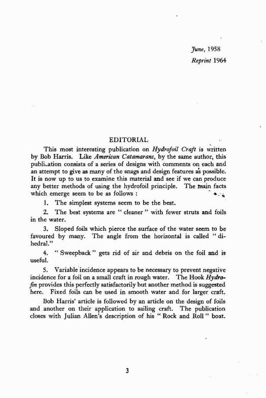
Gilruth, R. Gilruth with BilI Carl, aIso of the U.S. and of the N.A.C.A. started experimenting with foils in 1938. They successfully flew a catamaran hydrofoil sailing craft which took off at 5 knots and cruised at 12 knots. The main foil had an aspect ratio of I1 :l, a 12 foot span, a 1 foot chord and the remarkable LID ratio of 25:l. The foil section was one of big camber for high lift at low speed,
FIG. 1 2. Gilruth Hydrofoil Catnmnran Srrilin# Craft - Fail Borne
1 S
like N.A.C.A. 65-506. Gilruth's work later formed the basis for high speed configuration proposals to the Office of Naval Research, which resulted in the first Navy contract in 1947 for research on hydrofoils. /
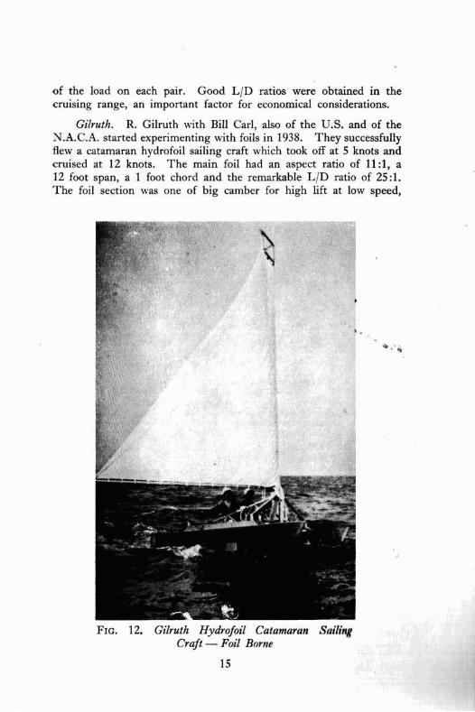
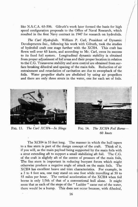
The Car1 Hydrofm'Es. William P. Carl, President of Dynamic 1
Deve1opments.-Inc., following his work with Gilruth, took the studies of hydrofoil craft one stage further with the XCH4. This craft has flown well over 65 knots, and according to Mr. Carl, owes its success to its fixed foil system. Longitudinal dynamic stability is obtained from proper adjustment of foil areas and their proper location in relation to the C.G. Transverse stability and area rontroI are obtained from sur- face breaking dihedral and spacing of the main foils. Reduction af air entrainment and retardation of cavitation are due to sweepback of the foils. Water propellor shafts ate abolished by using air propellers and there are only three struts in the water, one for each set af foils.
Frc. 14. The SCII4 Foil Bomc- 60 knots
The XCH4 is 53 feet long. The manner in which the hull tapers to a fine stern is part of the design concept of the craft. Think of it, if you will, as the main payload being supported by the main foils with a strut extending aft to support a srnaIl stabilizing aft foil. The C.G. of the craft is slightly aft of the centre of pressure of the main foils, T h e fine stern is important in reducing buoyant forces which might otherwise produce a negative angle of attack on the main foils. The XCH4 has excellent heave and trim characteristics. For example, in a 3 to 4 foot sea, one may stand on one foot while travelling at 50 to 55 miles per hour. The vertical acceleration of the XCH4 when foil borne is only 115th of that of a conventional hull alone. It might seem that as each of the steps of the " Ladder " came out of the water, there wouId be a bump. This does not occur because, with dihedral,

the upper foil wiIl partially enter or leave the water before the foil immediately beneath it enters or leaves the interface.
It may be possible ta foresee still another design concept in such a craft as the XCH4. This is, that at the speeds when the hydro- foils might otherwise become unstable or commence to lose Iift through mvitation, the speed is great enough to cause a partial transfer nf the weight to the wings. The stub wings of the XCH4, which act as foil, supports could thus be designed to contribute stability and Iift even to surface craft. This is not as far-fetched as it might at first seem, considering that a hydrofoil boat is actually a low-flying machine, getting its lift from the foils instead of air wings. In fact, Bill Carl has patented the name " Sea Wings " for his hydrofoils.
However, as Mr. Carl points out, there comes a point where one should leave the water and fly. He believes that the 60 to 70 knot range will be suficient for surface craft. His latest hydrofoil system will permit the construction of vessels of from two to three thousand
FIG. 15. Grurnman Aircrafi Frc. I h. Grutnman 15 ft.
Engiirem'n~ Corp.'s Alumimum 15 ft. Aluminurn Runabout Foil Borne Rimabout Fitted with the Cm1 Sea
Wings
tons. This system h composed of two main foiIs set forward of the C.G. These foils are swept back and all surfaces are lifting with the exception of the main support strut. Attached to each is a small trimming tab which is hand controlkd and will aIlaw a slight adjust- ment of flight attitude, although this is not necessary for stable flight. The tail hi1 is submerged and i s set as far from the main loil~ aa the vehicle will permit. Some adjustment may be made ta it hut not in flight. Cln the latmt model, it is a swept hack, ~yrnrnrtrienl designed to carry about 15% of the total load.

Gibbs atid Cox. Gibbs and Cox, Naval Architects in the U.S., during the early 1950"s, developed an electrical impulse variable incidence contrnlled hydrofoi1 power craft. In this system, feelers out in front of the foils sense the water level electrically and pass the information to the main foil incidence control system which alters the angle of atta'ck of the foils accordingly, A more recent craft has a much more " mphisticated " electrical impulse system and is reported to be highly successful. I t is, in fact, an electrical version of the Hook system and a vast improvement.
FIG. 17. Gibbr n~rri (.'ox Irici(l~~trce Frc. 1 X. Gihbs rrnd COX I~rcidmce Controlled Boat ( 1 953) Foil Rorne Controlled Boat (1 957) FoiI Rome
CONCLUSION
The modern hydrofoil crah are highly successful whether Gibbs and Cox's latest craft which is an improvement on the Hook system or the fixed, self-trimming systems like Grunberg, Tietjens or the Iatest Schertel, Sachsen'berg system or " Supmm " craft.
However, it is particularly important to note that with a carefulIy designed and refined fixed system, the same required atabiEity a b u t all three axes is assured without the costly and difficuIt to maintain variable incidence controlled systems. With a simple, safe, fixed system, capable of high speeds, designers can now devote much needed attention to propulsion problems, new hull design concepts, large ship application and eventually large scale production for military, commercial and private use.

APOLOGIES
\Ire wish to apolrlgisc: if rvu have neglected to mention anyone who has developed and tested a hydrofoil system and would greatly appreciate hearing from any such persons or gmup.
ACKNOWLEDGMENTS
To Henry B. Suydanl of the PreIiminary Desi~n Dept., Grumrnan Aircraft Engineering Cnrp. and Williarn P. Carl, Pres. of Dynamic Developments, Inc. frrr their valuable help in the preparation of this paper.
THANKS
Sincere thanks to %tly Spiegel for her patient drafts of this paper.
* REFERENCES
1. See data nn Uenney-Brown Ship Stabilisers or Sperry Co.
2. " An Appraisal of Hydrofoil Supported Craft" by T. M. BuermaYtn,- Lt. Cdr. P. Lechcy, u.s.N., and Cdr. J. J. Stilwell, a.s.x. fmm the Society of Naval Architects and Marine Engineer's Transactions, Vol. 61.
3. " Progress in Hydrofoils " by Harvey B. Atkinson, Jr., a paper presented to the Head of the Department of English, History and Government of the U.S. Naval Academy, Feb. 1957,
4. " HydrafoiIs," a bi-monthly of the Amateur Yacht Research Society, edited by John Mor~vood, Woodacres, Hythe, Kent. England.
5. "Boats on StiIts," by Christopher Hook, Vol. 3, No. 33, issue nf " The New Scientist "-a British production.
6. " Note on the Possibility of Fitting Hydrofoils to a Flying Boat," Coornbes, L. P. and Davies, E. T. J., Nov. 1937. R.A.E. "Farn- borough, England, Report No. 8.A. 1440.
7. " The HydrofoiI, i ts Development and Application lttl W:rrur HrmnI Aircraft," by Henry Suydam and CViEliam E'. Carl.
8. Oflice of Naval Research Review+- Aup~nt, 1'3.57

THE DESIGN OF HYDROFOILS
Hydrofoils are the most exciting prospect for the further advance- ment of sailing and it is hoped that several people will be trying them out this year in one form or another. It is therefore worth while to give the main points in the design of surface piercing foils as a guide and in the hope that improvements will be forthcoming.
THE SECTIOX
R hydrofoil would ordinarily be given an aerofoil section were it not for the facts of (1) Cavitation, (2) Air entry and (3) It has to pierce the surface.
1. Cavitation occurs when the lessened pressure over the upper surface of the foil becomes less than that of the vapour density of water. When this happens, the water flaw over the surface is broken by a layer of water vapour which appears Iike a bubble along the foil and the Iift falls off.
2. Air e f i t y occurs when air gets ovcr the upper surface of the 'fog and is held there by the negative pressure.
3. A sharp entry is better for cutting the surface of the water than a rounded entry.
Thesupper Surface. To avoid cavitation and air entry, the upper surface should be shaped so that there are no places where the pressure is very IOW, such as occurs with aerofoils at the leading edge. This is best achieved by having the upper surface the arc of a circle. The pressure drop on the upper surface is then more or less the same all over the area.
The I m e * ,Twface. A flat lower surface is, apparently, quite satisfactory and is the easiest to make. The combination of a flat lower surface and an arc of a circle for the upper surface makes up what is called an " Ogival " section and is that usually used for surface- piercing hydrofoib with the modification as in the next paragraph.
The Entry. An agival section will have an even and low pressure drop over its upper surface to prevent cavitation and it has a sharp entry to cut the water. However, if one bisects the angle of entry of such a fail section of a thickness ratio of 12:1, one finds that the angle is about 15" from the lower flat surface and this would have to

be the angle of attack of the water, if it were not to cause a downward pressure on the fore part of the upper surface. Now, for the best ratio of lift to drag, one wants an angle of attack of about 5" and this can be achieved by raising the lower surface by 1160th of the chord at the fore end. The linc bisecting the leading angle of the section will then be 5" and there will be no downward pressure on the upper surface. The final section is shown in the drawing.
Thickness. Ilydrofoils of thickness to chord ratio of 12:l are ordinarily used, though 10:l has been suggested. The thicker foils will give more lift and therefore might get the craft off the water more quickly. But, they will also produce more drag for the same speed and cavitate sooner. A ratio of 10:l might prove better for sailing craft which are not so likely to reach very high speeds.
~ * . 9
THE PLAX FORM
The plan form of surface piercing foils must depend on three
factors : 1. Aspect Ratio.
2. The prevention of air entry.
3. Easy sea motion.
Aspect Ratio. This is the ratio of the span of the hydrofoil to the average chord. In essence, it is a measure of the ratio of the lift of the foil to the loss of lift at the free wing end or ends. Now, a surface piercing foil has to suffer surface losses which we cannot avoid so I regard such a foil as having only one " free end " or " wing- tip." I therefore think of a hydrofoil as only half a wing and, if we feel that a full foil should have an aspect ratio of 6:1, a surface-piercing foil need only have a ratio of 3 : l because it has only one wingtip. Another factor in the design of a surface-piercing foil is that it should have the same aspect ratio at various amounts of immersion. This is only possible with a triangular plan form. From these aspect ratio considerations, therefore, I believe that the best plan form for a hydrofoil is a triangle whose span is 14 times the maximum chord.
Air Entry. This condition, technically called " air entrainment " occurs when the upper surface of the foil becomes covcrcd with i~ir

which has got down from the surface. It is to be distinguished from l < cavitation,'" already described. \%'hen air entry occurs, the lift faIls off possibly to as little as one quarter of what it was before ; that side drops and may achieve a negative angle of incidence and the craft may " fly " straight into the water amid showers of plywood and a tremendous splash. It is a condition to avoid.
The cause of air entrainment is not that air is sucked down over the foil from the surface because it does not occur in smooth water. Its cause must surely be that, when such a foil meets a wave, it rises up and comes out through the opposite side, still rising. The foil is then almost or mmpletely free of the water and comes dawn into it again, bringing air with it. The negative pressure on the foil then kecps the air in position on the upper surface and the lift is not produced.
Methods of Prmention. 1. Messrs. Saunders Roe and others used to believe that air got to the upper surface of the foil by suction from the surface, and to prevent this, placed streamlined fillets (fences) across the faits. These were successfu! in preventing the " Crash dive " described ahove and so seemed to substantiate the theory. Hawever, it now appears that these fillets can be extremely smalI and still work so, to my way of thinking, their function is to act as point., from which the trapped air can escape when it has been taken
"dewn after a foil surfaces rather than as a method of preventing air getting down.
2, It is my belief that, with surface-piercing foils, there is no way of preventing air from covering the upper surface when it breaks through a wave. One's objective, therefore, must be to minimise the drop due to the loss of lift and to get the air off the foil as quickly as possible. 1 believe that both these things can be achieved by the use of a triangular plan form for the foil. This shape wilt only drop in proportion to the square mot of the Foss of Iift of the fail as mm- pared to a drop of far greater extent from a rectangular foil and hoth the sweepback of the trailing edge and the broadening shape will throw the air away quickly. I also feel that the greater waterline length of the triangular plan form will have fewer surface losses. These are quite severe and have possibly been the cause of the difficulty which experimentem find in getting off the surface.
Easy Sea Motion. \men a surface-piercing foil meets a wave, extra area is immediately brought into use and, because this area has had to be used to get the craft up in the first place, it must be lifting. Therefore, the craft will get a push up. This push will be mild or

severe depending on the plan shape of the foil. To be most satis- factory, the plan shape has to be almost rectangular. A triangular plan form such as I suggest will produce a blow upwards from a wave. This might not be disagreeabte but i f it were, hinging the foil at its forward end and having a spring at thc after end will lesscn thc blow, both by taking it on the spring but also by lessening the angle of attack of the foil. Indeed, such a spring would also increase the angle of incidence when the lift suddenly fell off with air entrainment and, as shown by Christopher Hook with the Hydrofin, this u4ll convert a " Crash " into a slight limp. The sprung foil may be avoided by increasing the anglc of dihedral to 60' but this entails a reduction of lift and therefore an increasc in size of thc foils.
Inci'dmce C.'ontrul. It is to be noted that the sprung foil, as sug- gested here with surface piercing foils, will be as effective as either the Hook system with cumbersome " feelers " er electronic incidence control. The " Crash dive " cannot Occur and the incidence control will be good. Hydrofoils, apparently, do not '"tall j' and, the flow will reseat itself if air entrainment occurs with an i ~ c r e m d anglc of attack, though, as stated by Roh Harris, theoretically, one should reduce this.
**.
DIHEDRAL
The most satisfactory angle of dihedraI for lifting foils is about MC. My own experiments showed that 30" was ton flat for a model,
FOIL AREA
The Be11 " Hydrodrome " had hydrofoils which developed 70 lbs. lift per square foot of area at 10 m.p.h. These foils were i~early horizontal and the vertical lift of more sloping foils could well be taken as the cminc of thc dihcdraI angle. For instance, foils at 4-0' of dihedral ~ u l d develop about 45 lhs. of vertical lift per square foot of area at 10 m.p.h.
SUMMARY
HydrofoiIs should he a simple ogival section with thc fore edge raised by 1160th of the chord. Thc thicknesslchord ratio should be l or l : . A triangular plan form with a root chord to span ratio of 1 :l$ may give a good aspect ratio, throw air clear and, if the after edge is sprung, give an easy sea motion. At 40" of dihedral, the vertical lift should be 45 ibs. per square foot at 10 knots.

PARALLEL FOILS
Surface piercing foils with dihedral have an inefficiency. This is the leeward acting force of the weather foil which has to be neutral- ised by the lee foil. This inefficiency has to be taken by a motor driven hydrofoil-borne boat but a sailing craft which has a side force from its sails may be able to overcome it.
The Fwwmd FuiIs. A sailing hydrofoil craft could have its two forward foils sloping upwards to lee as in the drawing. The angle from the horizontal will then both give the extra foil area which is wanted when a foil is pushed further into the water and it will absorb the side force of the sails on the weather side as well as to lee. The result of this improved efficiency may he that the angle of slope of thc foils muld be reduced with a greater lift to drag ratio.
The Stem FMX Ideally, one would xvmt the stern foil also to %lope up to lee as with the main foils. This is certainly possible as shown by the arlier Baker hydrofoil craft which is shown earlier, but
it needs appropriate positioning of the centre of gravity to absorb the forward capsizing moment of the sails. An inverted T stern foil might be b a t because it can take the forward capsizing moment of
24

the sails by a negative angle of incidence. This is also an inefftciency when it occurs. A method of having a retractable stem T foil is shown in the figure,
The Mechanism. To get the foils to slope up to lee on each tack, a mechanism must be used of which there are two kinds :
1. The foils ran he hinged at their tops so that they flap over on each tack. This system was invented (and patented) by Commander Fawcett. It could only be worked with symmetrical foils. The craft would have to come off the foils to put about or gybe.
'I' S
'Yl , ' -AI 1 - m ..-&+P
I ~ r l l m for mama! Irmfmq c l loll
2, The foils could be fitted to a vertical axle which worked on bearings at the ends of the outrigger. These foils would have to be changed for each tack by hand but an asymmetrical foil could be used with a higher lift to drag ratio. It is possible that the craft might not need to come off the foils to put about or gyhe.
A HYDROFOIL SAILlNG CRAFT The delightful drawing by N. G. A. Pearce shows what I beIieve
to be the ideal hydmfoil sailing craft with all parts in the water getting the greatest possible efficiency.
The HulE. The hull has some stability in itseIf, though it would be on the narrow side. Outrigged buoyancy would not be necessary,
25

therefore. The hydrofoils would give a Iittle buoyant stability in light winds or at moorings. Probably a11 that was m-anted.
The F o b . All three 611s wouId slope up to leeward, accurately to take the combined side force of thc sails and the weight of the craft. Thus, they would he a'bsntutcly right for the work they are to do. Adjustment of the angle of dihedral in flight might, however, be needed so that the lesser side force with a reaching wind could be met by a lessened angle. Each foil could be turned about a vertical axle for putting about.
Sailing. As I see it, the craft would be got on her foils with a beam wind. The foils m-odd be set at an angle of dihedral of about 30' and all made to slope up to leeward with them all aligned exactly fore and aft. The angle of Eeeway would thus make up their angle of attack.
As the craft gathered way, she M-odd rise on her foils and the apparent wind would p forward, so that the sails would have to be close hauled, even with a beam wind. The angle of dihedral would then be increased to 35" or W.

Putting About. For this manoeuvre, the actions would be as follows :
1. Put the weather foil on the other tack by twisting it around aft. It would act as a slight brake when aft but would still be lifting. F h e n turned right round, it would have to be givcn a sIight angle to the water flow and not placed fore and aft like the lee foil.
2. T h e stern foil ~ ,ould then be twisted around m d the craft would swing quickly through the wind.
3. Before the sails filled on the other tack, the weather foil might need to he given a slight " toe-in " to give it an angle of attack to the water flow.
4. As soon as the sails fill, the foil which is now to weather would be twisted to the other tack, the angles of attack of all the foils would be adjusted and the craft would be sailing. I
Gybing. It might be thought that gybing would need some especial handling fechnique. I cannot think, however, that it wciyld be at all different from coming about. The craft would be sailin2 somewhat faster than the windspeed when the real wind was on the quarter and, during the gybe, the sail would be weathercocking to windward.
Stewing. Twisting the stern foil as drawn, \vouId merely give a greater or lesser angle of attack to the water flow with an alteration in longitudinal trim. This might be adequate for steering but I rather doubt it. I believe that to steer with such a foil, the angle of dihedral would need to be altered rather than the angle of attack. Thus, by making the foil more vertical, the stern would sink slightly and an increased force would be produced to wenihm. The extra force would come from the more sideways slope of the angle of force on the foil. This action would also increase the angle of attack on the foil.
The Sail Rig. At the high speeds at which a hydrofoil craft would go, a good thrust to side force ratio of the rig seems to me to be more valuabIe than sheer sail area. It would also be necessary to have the rig easy to handle. I therefore feel that a simple fully battened mainsail (without jib) erected in the Ice Yacht manner would be best. T h e mast would need to be slightly raked aft.
27

ROCK AND ROLL BOATS
A man, standing at the end of a punt, can thrust a paddle straight down into the mter ; and it goes straight down. Or, he can thrust it down at a slight slant away from him ; and the paddle slides away as well as downwards, pulling his hands after it. The greater the slant, the farther and faster does the paddIe gain distance. This is shown diagrammatically in the three drawings on the Jeft of Fig. 1.
* . ., A better shape for the purpose would be a blade mounted at right angles to, the shaft as in the middle drawing of Fig. 1. Owing to the improved aspect ratio, it would develop a stronger pull.
These fixed types of hydrofoil use only the down thrust as a working 'stroke. In arder to make the upIift of the vane also effective, aIl that is needed is to make the vane swing to the desired angle auto- matically by pivoting it just forward of the centre of pressure and providing suitable stops as on the right of Fig. 1.
This idea inspired my first attempt at flap-vane propulsion. I chose an angle of setting of the vanes which was rather flat to give ample horizontal distance.
A rocker beam was mounted on a twin huIled craft to see-saw transversely. This lifted and depressed the vanes attached to its ends by vertical struts when the man-power engine started " marking time " on the treadles on each side of the fulcrum. Every down-stroke as well as every up-stroke was a working stroke. It was as if the man with his hvo legs was a twin cylinder steam engine in which each cylinder was double acting.
The thing worked but very slowIy and with great turbulence and wa.4ted effort. This was because the vanes were set to work a t an

angle of 20" each side of the horizontal to gain the long forward com- ponent. It was quite obvious that the vanes stalled and never worked to their best efficiency. Still, the craft went out and came back under its one man power.
In the next craft, weight and complications were saved by using a single float with a fixed transverse beam ; and by making the whole craft rock to work the vanes. Small balancing floats near the beam ends saved capsizing. The idea of long gliding strokes was abandoned and the forward propulsion came from the vanes set for an angle of 45". It was obvious that propulsive effort must come from direct lift in a horizontal direction and not from a slight gliding angle. The glider was thus metamorphosed into a pmpellor.
This " Roll b a t " was a tot better in efficiency than the previous one but the outrigged vanes were always getting fouI of mooring ropes so, to overcome this, I made a new craft to rock fore and aft. The single oscillating beam projecting straight forwards rigid with the h a t , carried a single vane. It was easy to see where i t u.as heading and, because it was pivoted to the bow, it wuld be swung 1atmIly for steering.

1. The vanes must be weighted to have neutral buoyancy.
2. The vane should have a high aspect ratio to reduce the time and distance lost during the flip over. Very narrow vanes arranged as a biplane are uvrth trying.
3. T h e vanes may be regarded as the blades of a propellor making fractional revolutions, first one way and then the other. Conceived as a propellor, the angle of incidence should be a lot finer than 45", say 15". Four wood screws positioned to butt against the metal ends, shown in the drawing, would give a simple means of adjustment.
4. A harmony must be sought between the osciIlation period of the boat and the resistance to oscillation of the vanes. If the vanes are too big or have too much pitch, the rocking motion lacks an even rhythm.
5. As the vanes use the same leading edge and opposite striking surfaces alternatively on each stroke, they must be symmetrical and of course, streamlined.
* . m . HYDROFOILS - A WARNING
At the time when I entered the hydrofoil boat development field in 1942 in South Africa and Kenya, there existed a lirtle bwok, Aero- nautical Sidel@hts, by Brian Worley, which contained an article on the basic snag to hydrofoil work and since this warning probably saved me thousands of pounds of wrong-tracking, I think it timely to pass on the substance of Worley's main point which seems to-day to bc ignored by most writers although it still remains perfectly true.
Unlike a floating hull that finds its own line of travel relative to the water surface by displacement, the hydrofoil is blind and only the angle of attack decides whether in fact you fly heavenwards or bottomwards. It follows that a careful study of just how the lifting force varies with the angle of attack is the commencement of wisdom far all persons contemplating the attachment of foils to a hull. Any one of hundreds of bmks on flight will show such graphs plntted in

thc f i~r~t l of C, against angle of attack and one sees a t once that a very prliicrful positive lift of we11 over a ton per square foot at speed can surltlcnly become an equally powerful negative force by a change of angle through only a few degrees. In fact to put it into Urorley's \lords, " the boat unless arrested by the buoyancy of the hull, p l u n g ~ towards the bottom." This is what has become to be known as the " nerative dive," conditioned by angle of attack and aggravated by the unpleasant tendency ltowards unsteadiness that coma from the sudden onset of air bleed on any forwardly placed set of foils.
'I'his danger has given rise to three schoob of thought in design, namely the Tietjens, the Schertel, the Grunberg and the Hook Hydro- fin, A proper understanding of these methods is essential, but first we must look closer at air bleed.
Hydrofoils are so small that their lift in air i s of course non- existent and we count entirely on the maintenance of water flow both above and below the foil section. In fact the Iift resulting from the upper side is much greater than that resulting from the under side so that, should the former be suddenly lost through any cause the reult will be much more powerful than, say, the sudden bursting of a front tyre in a motor car ; there will be a sudden drop at the bow and an immediate change of trim of the whde boat in the general direhim of Davy Jones.
We all know what happens, however, in an aeroplane when we pass into an air pocket, there is a sudden drop in altitude that is not nice but this is not accompanied by any sudden tendency to dive. This is because the designer has been careful to place the C.G. of the plane bang over the C.P. of the main supporting wing so that in fact we drop on a level keel and flight is not upset thereby. We know that such drops will not happen near the ground at the moment of landing and so we don't worry.
When air sneaks into a hydrofoil for any reason (surfacing, via the strut, or encouraged by weed at the point of piercing the surface in fixed foil beats) this sudden drop is bound to happen and Tietjens, knowing this, took care to copy aircraft practice by placing his main foil amidships and using only a very small tail foil as a balancing plane. In his boat the crash was not too bad and it was important not to stop by a hasty pull back on the throttle, He further swept the upper parts of the emerging foils forward to give a slight nose-up moment as this part came into action. However, the solution has the grave drawback of shortening the " wheel-base " which, for other reasons is bad and Schertel does not foI1ow this plan but relies on : (1) Partitions or screens on the front foil to prevent Tatera1 spread of air bleed ;
31

(2) Careful manipulation of the throttle combined with changes of angle of attack to keep the foil weIl down ; (3) The avoidance of severe sea conditions or, navigation as a displacement boat in these cases. (The reader will note that the so-called " fixed foil " of imaginary simplicity is aIready abandoned in practice for these reasons and that the piloting cslnnot be done except by trained men).
Next, Grunberg completely eliminated the negative dive danger by carrying the bow on a surface planing element that did not rely on any upper side lift and thus the idea of incidence control was born but clearly, if bounce of the bow end from wave to wave is to be avoided something better is called for, .particularly in the direction of bctter lateral stability control and smoothness.
The rather simple idea of lifting a hull out of the water on foils so as to take advantage of the known better characteristics of hydrofoils over hull bottoms is, in practice, almost pointless a s many amateurs have found to their cost since one soon tires of a boat that can only operate on a glassy flat surface and with fore and aft trim held to very close angular Iimits. Therefare a high lift-out and an ability to soar high over all small wave shapes (and negotiate the larger) is a sine qua non. The " passive " type of lateral recovery given by Vee shaped foils is not enough sin& the boat must be kept down so low that high speed travel over short waves is impossible. The day that the R,A.E.,
%fkr tests, put into maths the rules governing the powerful " active " type recpvery forces given by well spaced h n t foils {one positive force and one negative) governed by surface feeler and pilot corrections, a new system was born that offers, together with powerful feeks damping straight and level flight only indirectly connected to surface conditions. Briefly stated, this is the key to the U.S. Navy's reasons for selecting this method. Arms may inspire horror to the " stick and string" boatman but they provide fast, smooth and safe flight over rough seas and the system is already fulfilIing many useful functions of transport.


