
HYDRAULIC TRASH PUMP #WTP4800X
20
USER MANUAL Safety, Operation and Maintenance HYDRAULIC TRASH PUMP #WTP4800X E.H. Wachs Company 600 Knightsbridge Parkway Lincolnshire, IL 60069 www.turnvalves.com Copyright © 2017 E.H. Wachs Company. All rights reserved. This manual may not be reproduced in whole or in part without the written consent of E.H. Wachs Company. 1/2020 Ver. 3
Transcript of HYDRAULIC TRASH PUMP #WTP4800X
USER MANUAL Safety, Operation and Maintenance
HYDRAULIC TRASH PUMP
#WTP4800X
E.H. Wachs Company600 Knightsbridge ParkwayLincolnshire, IL 60069www.turnvalves.com
Copyright © 2017 E.H. Wachs Company. All rights reserved.This manual may not be reproduced in whole or in partwithout the written consent of E.H. Wachs Company.1/2020 Ver. 3

WTP4800X User Manual ◄ 3
TABLE OF CONTENTS
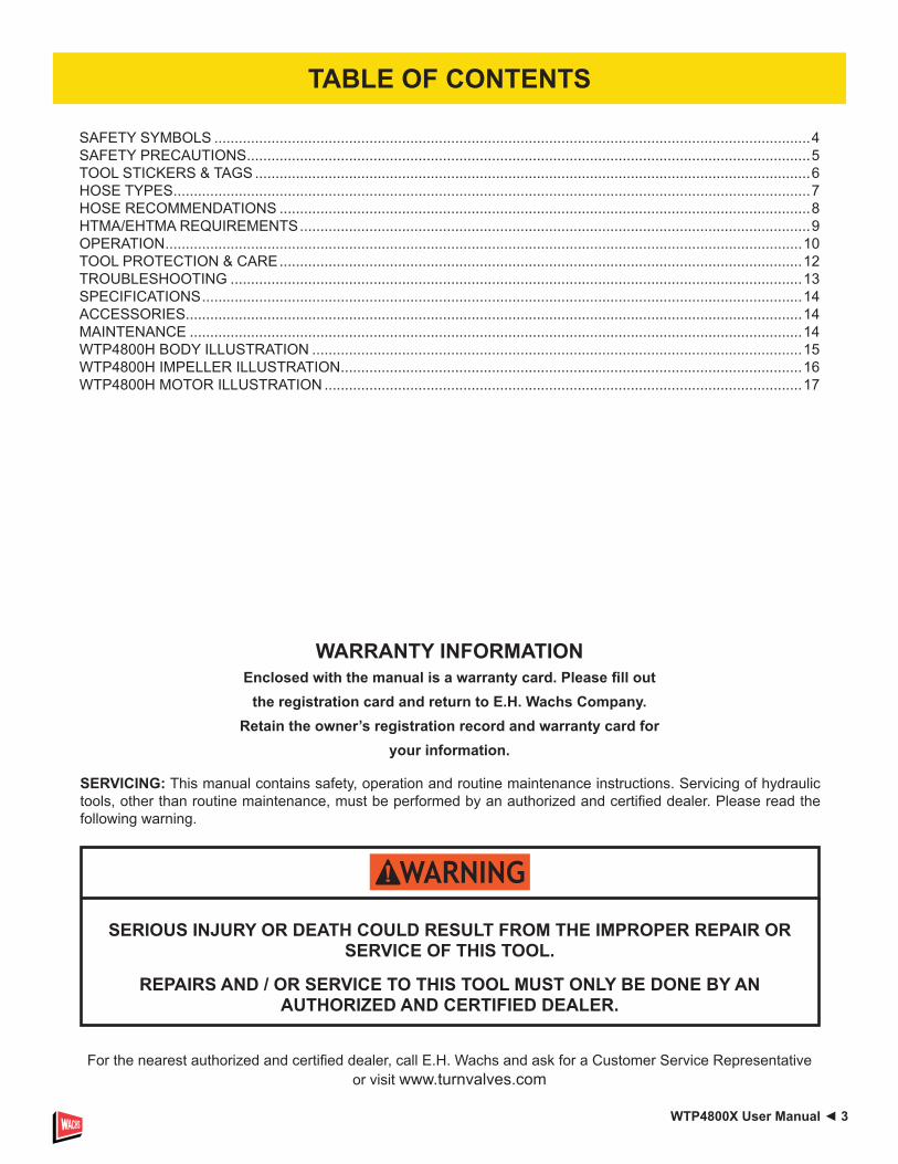
SAFETY SYMBOLS ..................................................................................................................................................4SAFETY PRECAUTIONS ..........................................................................................................................................5TOOL STICKERS & TAGS ........................................................................................................................................6HOSE TYPES ............................................................................................................................................................7HOSE RECOMMENDATIONS ..................................................................................................................................8HTMA/EHTMA REQUIREMENTS .............................................................................................................................9OPERATION ............................................................................................................................................................10TOOL PROTECTION & CARE ................................................................................................................................12TROUBLESHOOTING ............................................................................................................................................13SPECIFICATIONS ...................................................................................................................................................14ACCESSORIES.......................................................................................................................................................14MAINTENANCE ......................................................................................................................................................14WTP4800H BODY ILLUSTRATION ........................................................................................................................15WTP4800H IMPELLER ILLUSTRATION .................................................................................................................16WTP4800H MOTOR ILLUSTRATION .....................................................................................................................17
SERIOUS INJURY OR DEATH COULD RESULT FROM THE IMPROPER REPAIR OR SERVICE OF THIS TOOL.
REPAIRS AND / OR SERVICE TO THIS TOOL MUST ONLY BE DONE BY AN AUTHORIZED AND CERTIFIED DEALER.
SERVICING: This manual contains safety, operation and routine maintenance instructions. Servicing of hydraulic tools, other than routine maintenance, must be performed by an authorized and certified dealer. Please read the following warning.
For the nearest authorized and certified dealer, call E.H. Wachs and ask for a Customer Service Representative or visit www.turnvalves.com
WARRANTY INFORMATIONEnclosed with the manual is a warranty card. Please fill out
the registration card and return to E.H. Wachs Company.Retain the owner’s registration record and warranty card for
your information.

4 ► WTP4800X User Manual
Always observe safety symbols. They are included for your safety and for the protection of the tool.
LOCAL SAFETY REGULATIONSEnter any local safety regulations here. Keep these instructions in an area accessible to the operator and maintenance personnel.
Safety symbols and signal words, as shown below, are used to emphasize all operator, maintenance and repair actions which, if not strictly followed, could result in a life-threatening situation, bodily injury or damage to equipment.
This is the safety alert symbol. It is used to alert you to potential personal injury hazards. Obey all safety messages that follow this symbol to avoid possible injury or death.
This safety alert and signal word indicates an imminently hazardous situation which, if not avoided, will result in death or serious injury.
This safety alert and signal word indicates a potentially hazardous situation which, if not avoided, could result in death or serious injury.
This safety alert and signal word indicates a potentially hazardous situation which, if not avoided, could result in death or serious injury.
This signal word indicates a potentially hazardous situation which, if not avoided, may result in property damage.
This signal word indicates a situation which, if not avoided, will result in damage to the equipment.
This signal word indicates a situation which, if not avoided, may result in damage to the equipment.
SAFETY SYMBOLS

WTP4800X User Manual ◄ 5
Tool operators and maintenance personnel must always comply with the safety precautions given in this manual and on the stickers and tags attached to the tool and hose.These precautions are given for your safety. Review them carefully before operating the tool and before performing maintenance.Supervising personnel should develop additional precautions relating to the specific work area and local safety regulations. Place the added precautions on page 4.The WTP4800H Hydraulic Trash Pump will provide safe and dependable service if operated in accordance with the instructions given in this manual. Read and understand this manual and any stickers and tags attached to the tool and hoses before operation. Failure to do so could result in personal injury or equipment damage.
• Operator must start in a work area without bystanders. The operator must be familiar with all prohibited work areas such as excessive slopes and dangerous terrain conditions.
• Establish a training program for all operators to ensure safe operations.
• Do not operate the tool unless thoroughly trained or under the supervision of an instructor.
• Always wear safety equipment such as goggles, head protection and safety shoes at all times when operating the tool.
• Do not inspect or clean the tool while the hydraulic power source is connected. Accidental engagement of the tool can cause serious injury.
• Do not install or remove this tool while the hydraulic power source is connected. Accidental engagement of the tool can cause serious injury.
• Never operate the tool near energized transmission lines. Know the location of buried or covered services before starting work.
• Do not wear loose fitting clothing when operating the tool. Loose fitting clothing can become entangled with the tool and cause serious injury.
• Supply hoses must have a minimum working
pressure rating of 2500 psi/175 bar.• Be sure all hose connections are tight.• The hydraulic circuit control valve must be in the
“OFF” position when coupling or uncoupling the tool. Wipe all couplers clean before connecting. Failure to do so may result in damage to the quick couplers and cause overheating. Use only lint-free cloths.
• Do not operate the tool at oil temperatures above 140 °F/60 °C. Operation at higher oil temperatures can cause operator discomfort and may cause damage to the tool.
• Do not operate a damaged, improperly adjusted or incompletely assembled tool.
• To avoid personal injury or equipment damage, all tool repair, maintenance and service must only be performed by authorized and properly trained personnel.
• Do not exceed the rated limits of the tool or use the tool for applications beyond its design capacity.
• Always keep critical tool markings, such as labels and warning stickers, legible.
• Always replace parts with replacement parts recommended by Wachs.
• Check fastener tightness often and before each use.• Do not put your hands, or any other body part, under
the volute while the trash pump is running.• Do not lift the trash pump by pulling on the hydraulic
hoses. Use a suitable line fastened to the trash pump handle.
• Do not point water discharge toward bystanders.
SAFETY PRECAUTIONS

6 ► WTP4800X User Manual
SAFETY TAG P/N STN-15875 (Shown smaller then actual size)
D A N G E RD A N G E R
READ OPERATION MANUAL AND SAFETY INSTRUCTIONS FOR THIS
TOOL BEFORE USING IT.
USE ONLY PARTS AND REPAIR PROCEDURES APPROVED BY
WACHS AND DESCRIBED IN THE OPERATION MANUAL.
TAG TO BE REMOVED ONLY BY TOOL OPERATOR.
SEE OTHER SIDE
1. FAILURE TO USE HYDRAULIC HOSE LABELED AND CER-TIFIED AS NON-CONDUCTIVE WHEN USING HYDRAULIC TOOLS ON OR NEAR ELECTRICAL LINES MAY RESULT IN DEATH OR SERIOUS INJURY.BEFORE USING HOSE LABELED AND CERTIFIED AS NON-CONDUCTIVE ON OR NEAR ELECTRIC LINES BE SURE THE HOSE IS MAINTAINED AS NON-CONDUCTIVE. THE HOSE SHOULD BE REGULARLY TESTED FOR ELECTRIC CUR-RENT LEAKAGE IN ACCORDANCE WITH YOUR SAFETY DEPARTMENT INSTRUCTIONS.
2. A HYDRAULIC LEAK OR BURST MAY CAUSE OIL INJEC-TION INTO THE BODY OR CAUSE OTHER SEVERE PERSONAL INJURY.A. DO NOT EXCEED SPECIFIED FLOW AND PRESSURE
FOR THIS TOOL. EXCESS FLOW OR PRESSURE MAY CAUSE A LEAK OR BURST.
B. DO NOT EXCEED RATED WORKING PRESSURE OF HYDRAULIC HOSE USED WITH THIS TOOL. EXCESS PRESSURE MAY CAUSE A LEAK OR BURST.
C. CHECK TOOL HOSE COUPLERS AND CONNECTORS DAILY FOR LEAKS. DO NOT FEEL FOR LEAKS WITH YOUR HANDS. CONTACT WITH A LEAK MAY RESULT IN SEVERE PERSONAL INJURY.
I M P O R T A N T
D. DO NOT LIFT OR CARRY TOOL BY THE HOSES. DO NOT ABUSE HOSE. DO NOT USE KINKED, TORN OR DAMAGED HOSE.
3. MAKE SURE HYDRAULIC HOSES ARE PROPERLY CON-NECTED TO THE TOOL BEFORE PRESSURING SYSTEM. SYSTEM PRESSURE HOSE MUST ALWAYS BE CON-NECTED TO TOOL “IN” PORT. SYSTEM RETURN HOSE MUST ALWAYS BE CONNECTED TO TOOL “OUT” PORT. REVERSING CONNECTIONS MAY CAUSE REVERSE TOOL OPERATION WHICH CAN RESULT IN SEVERE PERSONAL INJURY.
4. DO NOT CONNECT OPEN-CENTER TOOLS TO CLOSED-CENTER HYDRAULIC SYSTEMS. THIS MAY RESULT IN LOSS OF OTHER HYDRAULIC FUNCTIONS POWERED BY THE SAME SYSTEM AND/OR SEVERE PERSONAL INJURY.
5. BYSTANDERS MAY BE INJURED IN YOUR WORK AREA. KEEP BYSTANDERS CLEAR OF YOUR WORK AREA.
6. WEAR HEARING, EYE, FOOT, HAND AND HEAD PRO-TECTION.
7. TO AVOID PERSONAL INJURY OR EQUIPMENT DAMAGE, ALL TOOL REPAIR MAINTENANCE AND SERVICE MUST ONLY BE PERFORMED BY AUTHORIZED AND PROPERLY TRAINED PERSONNEL.
I M P O R T A N T
READ OPERATION MANUAL AND SAFETY INSTRUCTIONS FOR THIS
TOOL BEFORE USING IT.
USE ONLY PARTS AND REPAIR PROCEDURES APPROVED BY
WACHS AND DESCRIBED IN THE OPERATION MANUAL.
TAG TO BE REMOVED ONLY BY TOOL OPERATOR.
SEE OTHER SIDE
The safety tag (P/N STN-15875) at right is attached to the tool when shipped from the factory. Read and understand the safety instructions listed on this tag before removal. We suggest you retain this tag and attach it to the tool when not in use.
NOTE:THE INFORMATION LISTED ON THE STICKERS SHOWN, MUST BE LEGIBLE AT ALL TIMES. REPLACE DECALS IF THEY BECOME WORN OR DAMAGED. REPLACEMENTS ARE AVAILABLE FROM YOUR LOCAL WACHS DISTRIBUTOR.
STN-09612General Caution Decal
TOOL STICKERS & TAGS
WTP4800X User Manual ◄ 7
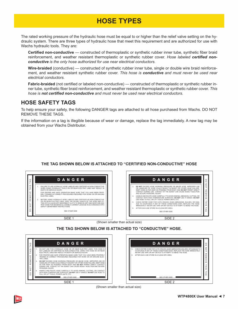
The rated working pressure of the hydraulic hose must be equal to or higher than the relief valve setting on the hy-draulic system. There are three types of hydraulic hose that meet this requirement and are authorized for use with Wachs hydraulic tools. They are:
Certified non-conductive — constructed of thermoplastic or synthetic rubber inner tube, synthetic fiber braid reinforcement, and weather resistant thermoplastic or synthetic rubber cover. Hose labeled certified non-conductive is the only hose authorized for use near electrical conductors.Wire-braided (conductive) — constructed of synthetic rubber inner tube, single or double wire braid reinforce-ment, and weather resistant synthetic rubber cover. This hose is conductive and must never be used near electrical conductors.Fabric-braided (not certified or labeled non-conductive) — constructed of thermoplastic or synthetic rubber in-ner tube, synthetic fiber braid reinforcement, and weather resistant thermoplastic or synthetic rubber cover. This hose is not certified non-conductive and must never be used near electrical conductors.
HOSE SAFETY TAGSTo help ensure your safety, the following DANGER tags are attached to all hose purchased from Wachs. DO NOT REMOVE THESE TAGS.If the information on a tag is illegible because of wear or damage, replace the tag immediately. A new tag may be obtained from your Wachs Distributor.
THE TAG SHOWN BELOW IS ATTACHED TO “CERTIFIED NON-CONDUCTIVE” HOSE
THE TAG SHOWN BELOW IS ATTACHED TO “CONDUCTIVE” HOSE.(Shown smaller than actual size)
SIDE 1
D A N G E R1. FAILURE TO USE HYDRAULIC HOSE LABELED AND CERTIFIED AS NON-CONDUCTIVE
WHEN USING HYDRAULIC TOOLS ON OR NEAR ELECTRIC LINES MAY RESULT IN DEATH OR SERIOUS INJURY.FOR PROPER AND SAFE OPERATION MAKE SURE THAT YOU HAVE BEEN PROP-ERLY TRAINED IN CORRECT PROCEDURES REQUIRED FOR WORK ON OR AROUND ELECTRIC LINES.
2. BEFORE USING HYDRAULIC HOSE LABELED AND CERTIFIED AS NON-CONDUCTIVE ON OR NEAR ELECTRIC LINES. WIPE THE ENTIRE LENGTH OF THE HOSE AND FIT-TING WITH A CLEAN DRY ABSORBENT CLOTH TO REMOVE DIRT AND MOISTURE AND TEST HOSE FOR MAXIMUM ALLOWABLE CURRENT LEAKAGE IN ACCORDANCE WITH SAFETY DEPARTMENT INSTRUCTIONS.
SEE OTHER SIDE
SIDE 2
DO
NO
T R
EM
OV
E T
HIS
TA
G
3. DO NOT EXCEED HOSE WORKING PRESSURE OR ABUSE HOSE. IMPROPER USE OR HANDLING OF HOSE COULD RESULT IN BURST OR OTHER HOSE FAILURE. KEEP HOSE AS FAR AWAY AS POSSIBLE FROM BODY AND DO NOT PERMIT DIRECT CONTACT DURING USE. CONTACT AT THE BURST CAN CAUSE BODILY INJECTION AND SEVERE PERSONAL INJURY.
4. HANDLE AND ROUTE HOSE CAREFULLY TO AVOID KINKING, ABRASION, CUTTING, OR CONTACT WITH HIGH TEMPERATURE SURFACES. DO NOT USE IF KINKED. DO NOT USE HOSE TO PULL OR LIFT TOOLS, POWER UNITS, ETC.
5. CHECK ENTIRE HOSE FOR CUTS CRACKS LEAKS ABRASIONS, BULGES, OR DAM-AGE TO COUPLINGS IF ANY OF THESE CONDITIONS EXIST, REPLACE THE HOSE IMMEDIATELY. NEVER USE TAPE OR ANY DEVICE TO ATTEMPT TO MEND THE HOSE.
6. AFTER EACH USE STORE IN A CLEAN DRY AREA.
SEE OTHER SIDE
D A N G E R
DO
NO
T R
EM
OV
E T
HIS
TA
G D A N G E R
(Shown smaller than actual size)SIDE 2
5. CHECK ENTIRE HOSE FOR CUTS CRACKS LEAKS ABRASIONS, BULGES, OR DAMAGE TO COUPLINGS IF ANY OF THESE CONDITIONS EXIST, REPLACE THE HOSE IMMEDIATELY. NEVER USE TAPE OR ANY DEVICE TO ATTEMPT TO MEND THE HOSE.
6. AFTER EACH USE STORE IN A CLEAN DRY AREA.
D A N G E R DO
NO
T R
EM
OV
E T
HIS
TA
G
D A N G E R
SIDE 1
1. DO NOT USE THIS HYDRAULIC HOSE ON OR NEAR ELECTRIC LINES. THIS HOSE IS NOT LABELED OR CERTIFIED AS NON-CONDUCTIVE. USING THIS HOSE ON OR NEAR ELECTRICAL LINES MAY RESULT IN DEATH OR SERIOUS INJURY.
2. FOR PROPER AND SAFE OPERATION MAKE SURE THAT YOU HAVE BEEN PROPERLY TRAINED IN CORRECT PROCEDURES REQUIRED FOR WORK ON OR AROUND ELEC-TRIC LINES.
3. DO NOT EXCEED HOSE WORKING PRESSURE OR ABUSE HOSE. IMPROPER USE OR HANDLING OF HOSE COULD RESULT IN BURST OR OTHER HOSE FAILURE. KEEP HOSE AS FAR AWAY AS POSSIBLE FROM BODY AND DO NOT PERMIT DIRECT CONTACT DURING USE. CONTACT AT THE BURST CAN CAUSE BODILY INJECTION AND SEVERE PERSONAL INJURY.
4. HANDLE AND ROUTE HOSE CAREFULLY TO AVOID KINKING, CUTTING, OR CONTACT WITH HIGH TEMPERATURE SURFACES. DO NOT USE IF KINKED. DO NOT USE HOSE TO PULL OR LIFT TOOLS, POWER UNITS, ETC.D
O N
OT
RE
MO
VE
TH
IS T
AG D A N G E R
SEE OTHER SIDE SEE OTHER SIDE
HOSE TYPES

8 ► WTP4800X User Manual
Oil
Flow
Hos
e Le
ngth
sIn
side
Dia
met
erU
SE( P
ress
/Ret
urn)
Min
. Wor
king
Pre
ssur
eG
PMLP
MFE
ETM
ETER
SIN
CH
MM
PSI
BA
RC
ertifi
ed N
on-C
ondu
ctiv
e H
ose
- Fib
er B
raid
- fo
r Util
ity B
ucke
t Tru
cks
4-9
15-3
4up
to 1
0up
to 3
3/8
10B
oth
2250
155
Con
duct
ive
Hos
e - W
ire B
raid
or F
iber
Bra
id -D
O N
OT
USE
NEA
R E
LEC
TRIC
AL
CO
ND
UC
TOR
S4-
615
-23
up to
25
up to
7.5
3/8
10B
oth
2500
175
4-6
15-2
326
-100
7.5-
301/
213
Bot
h25
0017
5
5-10
.519
-40
up to
50
up to
15
1/2
13B
oth
2500
175
5-10
.519
-40
51-1
0015
-30
5/8
16B
oth
2500
175
5-10
.519
-40
100-
300
30-9
05/
816
Pre
ssur
e25
0017
5
3/4
19R
etur
n25
0017
5
10-1
338
-49
up to
50
up to
15
5/8
16B
oth
2500
175
10-1
338
-49
51-1
0015
-30
5/8
16P
ress
ure
2500
175
3/4
19R
etur
n25
0017
5
10-1
338
-49
100-
200
30-6
03/
419
Pre
ssur
e25
0017
5
125
.4R
etur
n25
0017
5
13-1
649
-60
up to
25
up to
85/
816
Pre
ssur
e25
0017
5
3/4
19R
etur
n25
0017
5
13-1
649
-60
26-1
008-
303/
419
Pre
ssur
e25
0017
5
125
.4R
etur
n25
0017
5
Figu
re 1
. Typ
ical
Hos
e C
onne
ctio
ns
Tool
to H
ydra
ulic
Circ
uit H
ose
Rec
omm
enda
tions
The
char
t to
the
rig
ht s
how
s re
com
men
ded
min
imum
hos
e di
amet
ers
for
vario
us h
ose
leng
ths
base
d on
gal
lons
per
min
ute
(GP
M)/
liter
s pe
r min
ute
(LP
M).
Thes
e re
com
men
da-
tions
are
inte
nded
to k
eep
retu
rn li
ne p
ress
ure
(bac
k pr
essu
re) t
o a
min
imum
acc
epta
ble
lev-
el to
ens
ure
max
imum
tool
per
form
ance
. Th
is c
hart
is in
tend
ed to
be
used
for
hydr
au-
lic to
ol a
pplic
atio
ns o
nly
base
d on
Wac
hs to
ol
oper
atin
g re
quire
men
ts a
nd s
houl
d no
t be
us
ed fo
r any
oth
er a
pplic
atio
ns.
All
hydr
aulic
hos
e m
ust h
ave
at le
ast a
rat
ed
min
imum
wor
king
pre
ssur
e eq
ual t
o th
e m
axi-
mum
hyd
raul
ic s
yste
m re
lief v
alve
set
ting.
A
ll hy
drau
lic h
ose
mus
t mee
t or e
xcee
d sp
ecifi
catio
ns a
s se
t for
th b
y SA
E J5
17.
PRES
SUR
E
RET
UR
N
<<<
FLO
W
FLO
W >
>>
HOSE RECOMMENDATIONS
WTP4800X User Manual ◄ 9
Flow Range
Nominal Operating Pressure (at the power supply outlet)
System relief valve setting (at the power supply outlet)
Maximum back pressure (at tool end of the return hose)
Measured at a max. fluid viscosity of: (at min. operating temperature)
Temperature: Sufficient heat rejection capacity to limit max. fluid temperature to: (at max. expected ambient temperature)
Min. cooling capacity at a temperature difference of between ambient and fluid temps NOTE: Do not operate the tool at oil temperatures above 140° F (60° C). Operation at higher temperatures can cause operator discomfort at the tool. Filter Min. full-flow filtration Sized for flow of at least: (For cold temp. startup and max. dirt-holding capacity)
Hydraulic fluid Petroleum based (premium grade, anti-wear, non-conductive) Viscosity (at min. and max. operating temps)
NOTE: When choosing hydraulic fluid, the expected oil temperature extremes that will be experienced in service determine the most suitable temperature viscosity characteristics. Hydraulic fluids with a viscosity index over 140 will meet the requirements over a wide range of operating temperatures.
*SSU = Saybolt Seconds Universal
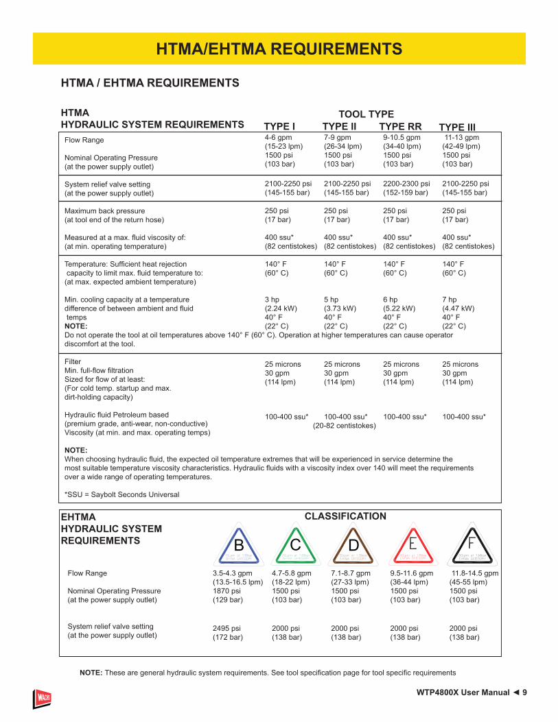
4-6 gpm 7-9 gpm 9-10.5 gpm 11-13 gpm (15-23 lpm) (26-34 lpm) (34-40 lpm) (42-49 lpm) 1500 psi 1500 psi 1500 psi 1500 psi (103 bar) (103 bar) (103 bar) (103 bar)
2100-2250 psi 2100-2250 psi 2200-2300 psi 2100-2250 psi (145-155 bar) (145-155 bar) (152-159 bar) (145-155 bar)
250 psi 250 psi 250 psi 250 psi (17 bar) (17 bar) (17 bar) (17 bar)
400 ssu* 400 ssu* 400 ssu* 400 ssu* (82 centistokes) (82 centistokes) (82 centistokes) (82 centistokes)
140° F 140° F 140° F 140° F (60° C) (60° C) (60° C) (60° C)
3 hp 5 hp 6 hp 7 hp (2.24 kW) (3.73 kW) (5.22 kW) (4.47 kW) 40° F 40° F 40° F 40° F (22° C) (22° C) (22° C) (22° C)
25 microns 25 microns 25 microns 25 microns 30 gpm 30 gpm 30 gpm 30 gpm (114 lpm) (114 lpm) (114 lpm) (114 lpm)
100-400 ssu* 100-400 ssu* 100-400 ssu* 100-400 ssu* (20-82 centistokes)
HTMA HYDRAULIC SYSTEM REQUIREMENTS
NOTE: These are general hydraulic system requirements. See tool specification page for tool specific requirements
TOOL TYPE
HTMA / EHTMA REQUIREMENTS
TYPE I TYPE II TYPE IIITYPE RR
B C D3.5-4.3 gpm 4.7-5.8 gpm 7.1-8.7 gpm 9.5-11.6 gpm 11.8-14.5 gpm(13.5-16.5 lpm) (18-22 lpm) (27-33 lpm) (36-44 lpm) (45-55 lpm)1870 psi 1500 psi 1500 psi 1500 psi 1500 psi(129 bar) (103 bar) (103 bar) (103 bar) (103 bar)
EHTMA HYDRAULIC SYSTEM REQUIREMENTS
CLASSIFICATION
Flow Range
Nominal Operating Pressure (at the power supply outlet)
System relief valve setting (at the power supply outlet)
2495 psi 2000 psi 2000 psi 2000 psi 2000 psi(172 bar) (138 bar) (138 bar) (138 bar) (138 bar)
HTMA/EHTMA REQUIREMENTS
10 ► WTP4800X User Manual
PREPARATION PROCEDURESCHECK POWER SOURCE1. Using a calibrated flow meter and pres sure gauge,
make sure the hydraulic power source develops a flow of 7-10 GPM/26-38 LPM at 2000 psi/140 bar.
2. Make certain that the power source is equipped with a relief valve set to open at 2100-2250 psi/145-155 bar maximum.
3. Make certain that the power source re turn pressure does not exceed 250 psi/17 bar.
4. Make sure the trash pump inlet is clear of debris. Remove any obstruction before operating.
CONNECT HOSES1. Wipe all hose couplers with a clean, lint free cloth
before making connections.
2.
Do not connect pressure to the return port. Motor shaft seal limit is 250 psl/17 bar.
Connect the hoses from the hydraulic power source to the couplers on the trash pump. Connect the return hose first and disconnect it last to minimize or avoid trapped pressure within the trash pump motor.
Note: If uncoupled hoses are left in the sun, pressure increase inside the hoses might make them difficult to connect. Whenever possible, connect the free ends of the hoses together.3. Observe the arrow on the couplers to ensure that the
flow is in the proper direc tion. The female coupler on the trash pump is the inlet (pressure) coupler.
PUMP OPERATION1. Observe all safety precautions.2. Attach a 4-inch/102 mm diameter fire hose to the
trash pump outlet. For best performance, keep the fire hose as short as possible and lay it out to avoid sharp bends or kinks.Do not attach a nozzle to the outlet end of the fire hose. The WTP4800 is designed for high GPM water flow at low water pressure (head).
3. Attach a rope or cable to the trash pump’s handle. Lower the trash pump into the liquid to be pumped. Do not raise or lower the trash pump by its hoses or couplers.
4.
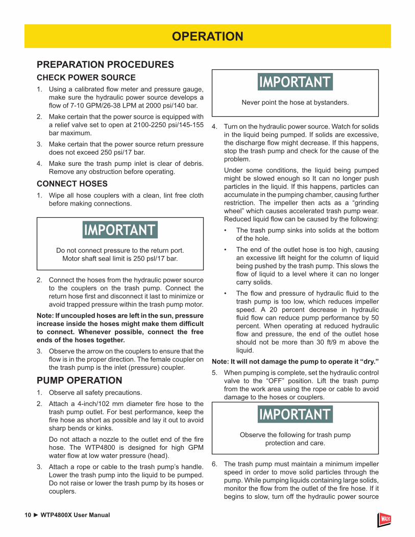
Never point the hose at bystanders.
Turn on the hydraulic power source. Watch for solids in the liquid being pumped. If solids are excessive, the discharge flow might decrease. If this happens, stop the trash pump and check for the cause of the problem.Under some conditions, the liquid being pumped might be slowed enough so It can no longer push particles in the liquid. If this happens, particles can accumulate in the pumping chamber, causing further restriction. The impeller then acts as a “grinding wheel” which causes acceler ated trash pump wear. Reduced liquid flow can be caused by the following:• The trash pump sinks into solids at the bottom
of the hole.• The end of the outlet hose is too high, causing
an excessive lift height for the column of liquid being pushed by the trash pump. This slows the flow of liquid to a level where it can no longer carry solids.
• The flow and pressure of hydraulic fluid to the trash pump is too low, which re duces impeller speed. A 20 percent de crease in hydraulic fluid flow can reduce pump performance by 50 percent. When operating at reduced hydraulic flow and pressure, the end of the outlet hose should not be more than 30 ft/9 m above the liquid.
Note: It will not damage the pump to operate it “dry.”5. When pumping is complete, set the hy draulic control
valve to the “OFF” posi tion. Lift the trash pump from the work area using the rope or cable to avoid damage to the hoses or couplers.
6.
Observe the following for trash pump protection and care.
The trash pump must maintain a mini mum impeller speed in order to move solid particles through the pump. While pumping liquids containing large solids, monitor the flow from the outlet of the fire hose. If it begins to slow, turn off the hydraulic power source
OPERATION

WTP4800X User Manual ◄ 11
OPERATION
and lift the trash pump from the work area. Disconnect the hydraulic hoses and clean at the water hose and the pumping chamber.
7.
Pumping liquids with a solids-to liquid ratio greater than 30 per cent will cause impeller wear.
To maintain optimum performance, it is good practice to periodically inspect the impeller for wear or damage. This is especially important following the pump ing of liquids containing sharp, abrasive solids.
COLD WEATHER OPERATIONIf the trash pump is to be used during cold weather, preheat the hydraulic fluid at low power source speed. When using recommended fluids, fluid should be at or above 50 °F/10 °C (400 ssu/82 centistokes) before use.Damage to the hydraulic system or pump motor seals can result if the fluid is too viscous or thick.

12 ► WTP4800X User Manual
• Make sure all couplers are wiped clean before connection.
• The hydraulic circuit control valve must be in the “OFF” position when coupling or uncoupling hydraulic tools. Failure to do so may result in damage to the quick couplers and cause overheating of the hydraulic system.
• Always store the tool in a clean dry space, safe from damage or pilferage.
• Make sure the circuit PRESSURE hose (with male quick disconnect) is connected to the “IN” port. The circuit RETURN hose (with female quick disconnect) is connected to the opposite port. Do not reverse circuit flow. This can cause damage to internal seals.
• Always replace hoses, couplings and other parts with replacement parts recommended by Wachs. Supply hoses must have a minimum working pressure rating of 2500 psi/172 bar.
• Do not exceed the rated flow or pressure (refer to “Specifications” on page 14 for correct flow rate and pressure). If specifications are exceeded, rapid failure of the internal seals may result.
In addition to the safety precautions found in this manual, observe the following for
equipment protection and care.
• Always keep critical tool markings, such as warning stickers and tags, legible.
• Tool repair should be performed by experienced personnel only.
• Make certain that the recommended relief valves are installed in the pressure side of the system.
• Do not use the tool for applications for which it was not intended.
TOOL PROTECTION & CARE

WTP4800X User Manual ◄ 13
If symptoms of poor performance develop, the following chart can be used as a guide to correct the problem.When diagnosing faults in operation of the tool, always make sure the hydraulic power source is supplying the correct hydraulic flow and pressure as listed in the table. Use a flowmeter know to be accurate. Check the flow with the hydraulic fluid temperature at least 80 °F/27 °C.
PROBLEM CAUSE SOLUTIONPump will not start. No hydraulic fluid flow or
pressure.Turn on power unit and check that 7–10 GPM/26-38 LPM at 2000 psi/140 bar is available at the trash pump.
Defective couplers. Check the couplers by connecting them together with the hydraulic power supply operating and with the control valve in the “ON” position. The power supply should operate without “loading” from the couplers.
Impeller jammed with debris. Clean the pumping chamber.Impeller rubbing against wear plates.
Check and adjust the impeller clearance.
Defective power module. Repair or replace the power module.Poor pump performance. Hydraulic flow reversed. Check that the hoses are correctly connected
to the pump motor ports. The female coupler should be connected to the “IN” port. The return fluid must never flow through a reversing valve.
Improper hydraulic fluid flow. Check that 7–10 GPM/26–38 LPM at 2000 psi/140 bar is available at the trash pump. A 20% decrease in flow can result in a 50% decrease in pump performance. 8 GPM/30 LPM is the optimum circuit flow.
Trash pump submersed in sediment.
Lift the pump from the bottom of the hole or chamber. Use a flat support under the pump if necessary.
Trash pump inlet restricted. Remove restriction and clean thoroughly.Discharge hose kinked or restricted.
Straighten the hose. If the hose must bend at the top of the hole, use a piece of split rigid conduit with large diameter of the expanded hose. This keeps the hose from kinking. Use a 90° 4-inch pipe elbow on the trash pump outlet if necessary.
Discharge hose too small. Use a 4-inch diameter fire hose.Water lift too high. Lower the outlet end of the discharge hose.Impeller worn or damaged. Check impeller for damage and excessive wear.
Replace if necessary.Wear plates worn or damaged. Check wear plates for damage and excessive
wear. Replace if necessary.Hydraulic fluid in discharge flow.
Motor shaft seal failure. Replace the motor shaft seal. Ensure power unit is delivering 7-10 GPM/26-38 LPM
TROUBLESHOOTING
14 ► WTP4800X User Manual
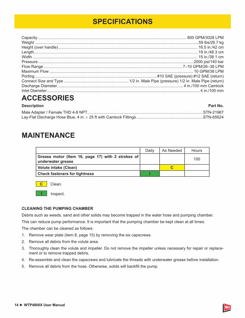
Capacity...................................................................................................................................... 800 GPM/3028 LPMWeight ...................................................................................................................................................59 lbs/26.7 kgHeight (over handle) ............................................................................................................................. 16.5 in./42 cmLength................................................................................................................................................... 19 in./48.3 cmWidth .................................................................................................................................................... 15 in./38.1 cmPressure ........................................................................................................................................... 2000 psi/140 barFlow Range ............................................................................................................................ 7–10 GPM/26–38 LPMMaximum Flow ................................................................................................................................. 10 GPM/38 LPMPorting ............................................................................................................. #10 SAE (pressure) #12 SAE (return)Connect Size and Type .......................................................... 1/2 in. Male Pipe (pressure) 1/2 in. Male Pipe (return)Discharge Diameter ................................................................................................................. 4 in./100 mm CamlockInlet Diameter ......................................................................................................................................... 4 in./100 mm
ACCESSORIESDescription Part No.Male Adapter / Female THD 4-8 NPT ........................................................................................................STN-21967Lay-Flat Discharge Hose Blue, 4 in. × 25 ft with Camlock Fittings ............................................................STN-65624
MAINTENANCE
Daily As Needed HoursGrease motor (Item 16, page 17) with 2 strokes of underwater grease 100
Volute intake (Clean) CCheck fasteners for tightness I
Clean.
Inspect.
C
I
CLEANING THE PUMPING CHAMBERDebris such as weeds, sand and other solids may become trapped in the water hose and pumping chamber.This can reduce pump performance. It is important that the pumping chamber be kept clean at all times. The chamber can be cleaned as follows:1. Remove wear plate (item 8, page 15) by removing the six capscrews.2. Remove all debris from the volute area.3. Thoroughly clean the volute and impeller. Do not remove the impeller unless necessary for repair or replace-
ment or to remove trapped debris.4. Re-assemble and clean the capscrews and lubricate the threads with underwater grease before installation.5. Remove all debris from the hose. Otherwise, solids will backfill the pump.
SPECIFICATIONS

WTP4800X User Manual ◄ 15
WTP4800 BODY ILLUSTRATION
ITEM P/N QTY DESCRIPTION
1 STN-00719 6 Nut
2 STN-15664 6 Washer
3 STN-21967 1 Camlock Coupler
4 STN-21964 1 Wear Plate
5 STN-71939 3 Bolt
6 STN-81210 1 Volute Foot
7 STN-71939 3 Bolt
1
2
3
4
5
6
7
16 ► WTP4800X User Manual
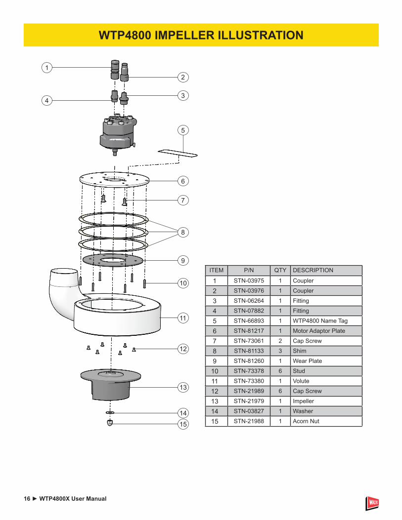
WTP4800 IMPELLER ILLUSTRATION
ITEM P/N QTY DESCRIPTION
1 STN-03975 1 Coupler
2 STN-03976 1 Coupler
3 STN-06264 1 Fitting
4 STN-07882 1 Fitting
5 STN-66893 1 WTP4800 Name Tag
6 STN-81217 1 Motor Adaptor Plate
7 STN-73061 2 Cap Screw
8 STN-81133 3 Shim
9 STN-81260 1 Wear Plate
10 STN-73378 6 Stud
11 STN-73380 1 Volute
12 STN-21989 6 Cap Screw
13 STN-21979 1 Impeller
14 STN-03827 1 Washer
15 STN-21988 1 Acorn Nut
12
34
5
6
7
8
9
10
11
12
13
14
15

WTP4800X User Manual ◄ 17
ITEM P/N QTY DESCRIPTION
1 STN-21987 2 Cap Screw
2 STN-21986 3 Cap Screw
3 STN-82595 1 Motor Cap
4 STN-15385 1 O-ring
5 STN-21974 1 Gear
6 STN-21982 1 Gear
7 STN-21984 1 Idler Shaft
8 STN-19793 1 Bushing
9 STN-22065 2 Dowel Pin
10 STN-82592 1 Flange
11 STN-82594 1 Shaft
12 STN-82602 1 Woodruff Key
13 STN-19793 1 Bushing
14 STN-20680 2 Bearing Washer
15 STN-08020 1 Thrust Bearing
16 STN-26812 1 Retaining Ring
17 STN-73064 1 Quad Ring
18 STN-06311 1 V-ring
19 02905 1 O-ring
20 82593 1 Seal Gland
21 STN-25278 1 Retaing Ring
WTP4800 MOTOR ILLUSTRATION
12
3
4
56
78
9
10
1112
13
1415
16
17
18
19
2021

18 ► WTP4800H User Manual
DECLARATIONS OF CONFORMITY
Test Report #07072016TP08
DECLARATION OF CONFORMITY ÜBEREINSTIMMUNGS-ERKLARUNG DECLARATION DE CONFORMITE CEE DECLARACION DE CONFORMIDAD DICHIARAZIONE DI CONFORMITA
______________________________________________________________________ I, the undersigned: Ich, der Unterzeichnende: Je soussigné: El abajo firmante: lo sottoscritto:
Shravan Kumar Gunishetty
Surname and First names/Familiennname und Vornamen/Nom et prénom/Nombre y apellido/Cognome e nome
hereby declare that the equipment specified hereunder: bestätige hiermit, daß erklaren Produkt genannten Werk oder Gerät: déclare que l’équipement visé ci-dessous: Por la presente declaro que el equipo se especifica a continuación: Dichiaro che le apparecchiature specificate di seguito:
1. Category: Trash Pump, Hydraulic Kategorie: Catégorie: Categoria: Categoria:
2. Make/Marke/Marque/Marca/Marca STANLEY
3. Type/Typ/Type/Tipo/Tipo: TP08013, TP08013H, TP0813X, TP08013XB, TP08013XCS, TP08013XL11, TP08013XW
4. Serial number of equipment: Seriennummer des Geräts: Numéro de série de l’équipement: Numero de serie del equipo: Matricola dell´attrezzatura:
All
Has been manufactured in conformity with Wurde hergestellt in Übereinstimmung mit Est fabriqué conformément Ha sido fabricado de acuerdo con E’ stata costruita in conformitá con
Directive/Standards Richtlinie/Standards Directives/Normes Directriz/Los Normas Direttiva/Norme
No. Nr Numéro No n.
Approved body Prüfung durch Organisme agréé Aprobado Collaudato
EN Machinery Directive
809:1998+A1:2009 2006/42/EC:2006
Self Self Self
5. Special Provisions: None Spezielle Bestimmungen: Dispositions particulières: Provisiones especiales: Disposizioni speciali: 6. Representative in the Union: Patrick Vervier, Stanley Dubuis 17-19, rue Jules Berthonneau-BP 3406 41034 Blois Cedex, France. Vertreter in der Union/Représentant dans l’union/Representante en la Union/Rappresentante presso l’Unione Done at/Ort/Fait à/Dado en/Fatto a STANLEY Infrastructure, Portland, Oregon USA Date/Datum/le/Fecha/Data 1-5-11 Signature/Unterschrift/Signature/Firma/Firma Position/Position/Fonction/Cargo/Posizione Shravan Kumar Gunishetty Quality Engineer


E.H. Wachs Company600 Knightsbridge Parkway
Lincolnshire, IL 60069www.turnvalves.com