HY08-M1140-4
80
Miller HV2 Series Heavy Duty Industrial Hydraulic Cylinders Catalog HY08-M1140-4/NA January, 2011 Heavy Duty Service – Tie Rod Construction Nominal Pressure – 3000 PSI Standard Bore Sizes – 1.50" through 20.00" Piston Rod Diameters – 0.625" through 10.000" Seventeen Standard Mounting Styles
Transcript of HY08-M1140-4

Miller HV2 SeriesHeavy Duty Industrial Hydraulic Cylinders
Catalog HY08-M1140-4/NA January, 2011
Heavy Duty Service – Tie Rod ConstructionNominal Pressure – 3000 PSI
Standard Bore Sizes – 1.50" through 20.00"
Piston Rod Diameters – 0.625" through 10.000"
Seventeen Standard Mounting Styles

Heavy-Duty Hydraulic CylindersHV2 Series
Catalog HY08-M1140-4/NA
www.millerfluidpower.com
Miller Fluid PowerDes Plaines, ILMilton, Ontario Canada
MHP Series Cylinders Up to 210 BAR
CHE/CHD Series Compact Hydraulic Cylinders Up to 207 BAR
AV Series Cylinders Up to 250 PSI Permanently Lubricated
Our popularly-priced line of medium pressure hydraulic cylinders, with bore sizes from 1.00" to 8.00".
JV Series Cylinders 400-2300 PSI
(Pressures are bore size dependent.)
AV Series air cylinders are available in bore sizes from 1.50" through 20.00" and up to 250 PSI operating pressure. Standard NFPA dimensions and proven Miller design features.
CHE/CHD Series compact hydraulic cylinders are available in bore sizes from 20mm through 100mm and up to 207 BAR operating pressure.
MHP Series metric hydraulic cylinders are designed to meet the requirements of ISO 6020/2 (1991), 160 Bar Compact Series and may be used for working pressures up to 210 Bar. Bore sizes from 25mm through 200mm.
In line with our policy of continuing product improvement, specifications and information contained in this catalog are subject to change.Copyright ©2009, 2011 by Parker Hannifin Corporation. All rights reserved.PRINTED IN THE U.S.A.
WARNINGFAILURE OR IMPROPER SELECTION OR IMPROPER USE OF THE PRODUCTS AND/OR SYSTEMS DESCRIBED HEREIN OR RELATED ITEMS CAN CAUSE DEATH, PERSONAL INJURY AND PROPERTY DAMAGE.This document and other information from the Parker Hannifin Corporation, its subsidiaries and authorized distributors provide product and/or system options for further investigation by users having expertise. It is important that you analyze all aspects of your application, including consequences of any failure and review the information concerning the product or system in the current product catalog. Due to the variety of operating conditions and applications for these products or systems, the user, through its own analysis and testing, is solely responsible for making the final selection of the products and systems and assuring that all performance, safety and warning requirements of the application are met.The products described herein, including without limitation, product features, specifications, designs, availability and pricing, are subject to change by Parker Hannifin Corporation and its subsidiaries at any time without notice.
Offer of SaleThe items described in this document are hereby offered for sale by Parker Hannifin Corporation, its subsidiaries or its authorized distr butors. This offer and its acceptance are governed by provisions stated on a separate page of the document entitled Offer of Sale’.

1
www.millerfluidpower.com
Heavy-Duty Hydraulic CylindersHV2 Series
Catalog HY08-M1140-4/NA
Miller Fluid PowerDes Plaines, ILMilton, Ontario Canada
Table of Contents
Table of Contents Page Bore Sizes 1.50"-6.00" 7.00" & 8.00" Large BoresSpecifications, Mounting Styles ................................................................................3 ..................... 21 .................... 36-37 Cylinder Features ....................................................................................................4-5 .................... 21 .......................36Models 51, 52, 53 Tie Rods Extended Mounts (Both Ends NFPA MX1, Cap End NFPA MX2, Head End NFPA MX3).............6, 7 ................ 22, 23.................38, 39Model 61, Head Rectangular Flange Mount (NFPA MF1) .....................................8, 9 ................ 24, 25...................N/AModel 65, Head Square Flange Mount (NFPA MF5) .............................................8, 9 ................ 24, 25.................40, 41Model 67, Head Rectangular Mount (NFPA ME5) .................................................8, 9 ................ 24, 25.................40, 41Model 62, Cap Rectangular Flange Mount (NFPA MF2) .....................................10, 11 .............. 26, 27...................N/AModel 66, Cap Square Flange Mount (NFPA MF6) .............................................10, 11 .............. 26, 27.................42, 43Model 68, Cap Rectangular Mount (NFPA ME6) .................................................10, 11 .............. 26, 27.................42, 43Model 72, Side Lug Mount (NFPA MS2) ..............................................................12, 13 .............. 28, 29.................42, 43Model 74, Side Tap Mount (NFPA MS4) ..............................................................12, 13 .............. 28, 29...................N/AModel 84, Cap Fixed Clevis Mount (NFPA MP1) .................................................14, 15 ................. 32 ....................44, 45Model 81, Head Trunnion Mount (NFPA MT1) ....................................................16, 17 .............. 30, 31.................44, 45Model 82, Cap Trunnion Mount (NFPA MT2).......................................................16, 17 .............. 30, 31.................44, 45Model 89, Intermediate Trunnion Mount (NFPA MT4) .........................................16, 17 .............. 30, 31.................44, 45Model 87, Intermediate Trunnion Mount (NFPA MT4) ............................................18 .................... 33 ......................N/AModel 94, Spherical Bearing Mount (NFPA MPU3) ................................................19 ................... N/A .....................N/A
Spherical Bearing Cylinder Accessories ............................................................................................................................... 20Double Rod End Cylinders .............................................................................................................................................34, 46B & R Table – Bushing Retainer Style in 1.50" - 8.00" Bores .............................................................................................. 34Linear Alignment Couplers ................................................................................................................................................... 47Cylinder Accessories .......................................................................................................................................................48-51“Style 9” Piston Rod End, Split Couplers & Weld Plates ................................................................................................52, 53Push and Pull Forces ............................................................................................................................................................ 54Operating Fluids and Temperature Range ........................................................................................................................... 55Cylinder Pressure Ratings .................................................................................................................................................... 56Rod End Style 4 Minimum Stroke ......................................................................................................................................... 56Cylinder Weights ................................................................................................................................................................... 57Ports ................................................................................................................................................................................58, 59Stroke Data ........................................................................................................................................................................... 60Tie Rod Supports .................................................................................................................................................................. 60Stroke Adjusters .................................................................................................................................................................... 60Spherical Bearing Mount Application .................................................................................................................................... 61Stop Tube, Mounting Classes ............................................................................................................................................... 62Piston Rod Selection Chart and Data .............................................................................................................................63, 64Thrust Key Mountings ........................................................................................................................................................... 65Rod Bushing Drain ................................................................................................................................................................ 65End-of-Stroke Magnetic Principle Type Proximity Switch .................................................................................................... 66Parts List, Piston and Rod Assemblies ................................................................................................................................. 67Parts Identification, Seal Kits ...........................................................................................................................................68-71How to Order HV2 Series Cylinders ...............................................................................................................................72, 73Cylinder Safety Guide .....................................................................................................................................................74, 75Offer of Sale ........................................................................................................................................................................ IBC

Heavy-Duty Hydraulic CylindersHV2 Series
Catalog HY08-M1140-4/NA
2
www.millerfluidpower.com
Miller Fluid PowerDes Plaines, ILMilton, Ontario Canada
Features
Miller Fluid Power HV2 Series Heavy-Duty Hydraulic Cylinder When the application demands a heavy-duty cylinder with maximum performance, specify Miller Fluid Power HV2 Series. This cylinder has standard design features to maximize machine uptime. The standard bronze rod bushing (nodular iron is a no extra cost option), case-hardened piston rod, high strength piston rod stud and tie rod material combine to make HV2 the cylinder for demanding applications up to 3000 psi.
Thorough inspection and performance testing of each cylinder before shipment assure HV2 cylinder quality. See the following pages for the inside story on all the features that make HV2 series the high performance, long lasting choice for all your heavy-duty hydraulic applications.

3
www.millerfluidpower.com
Heavy-Duty Hydraulic CylindersHV2 Series
Catalog HY08-M1140-4/NA
Miller Fluid PowerDes Plaines, ILMilton, Ontario Canada
Specifications / Mountings
Standard Specifications• Heavy Duty Service – ANSI/(NFPA) T3.6.7R2-1996 Mounting and Specification Dimensions• Standard Construction – Square Head – Tie Rod Design• Nominal Pressure – 3000 PSI1
• Standard Fluid – Hydraulic Oil• Standard Temperature – -10° F to +165° F• Bore Sizes – 1.50" through 6.00" • Piston Rod Diameter – 0.625" through 4.000"• Mounting Styles – 17 standard styles at various application ratings
• Standard – Externally removable bolted bushing assembly
• Strokes – Available in any practical stroke length• Cushions – Optional at either end or both ends of stroke. “Float Check” at cap end.• Rod Ends – Three Standard Choices – Specials to Order
1 If hydraulic operating pressure exceeds 3000 PSI, send application data for engineering evaluation and recommendation. See cylinder pressure ratings page for actual design factors.
In line with our policy of continuing product improvement, specifications in this catalog are subject to change.
Mounting StylesTie Rods Extended Head Rectangular Flange
Model 61
Head Square Flange Head Rectangular
Cap Rectangular Flange
Model 62
Cap Square Flange Cap Rectangular Side Lug
Side Tap Cap Fixed Clevis Cap Fixed Eye with Spherical Bearing
Head Trunnion
Cap Trunnion Intermediate Trunnion
(NFPA MF1)
Both Ends Model 51 Cap End Model 52
Head End Model 53
(BOTH ENDS NFPA MX1) (CAP END NFPA MX2) (HEAD END NFPA MX3)
Model 65
(NFPA MF5)
Model 67
(NFPA ME5)
(NFPA MF2)
Model 66
(NFPA MF6)
Model 68
(NFPA ME6)
Model 72
(NFPA MS2)
Model 74
(NFPA MS4)
Model 84
(NFPA MP1)
Model 94
(NFPA MPU3)
Model 81
(NFPA MT1)
Model 82
(NFPA MT2)
Model 87 (4.00"-6.00"
bores)
(NFPA MT4)
Intermediate Trunnion
Model 892
(NFPA MT4)2 Reduced rating 3.25"-6.00" bores

4
www.millerfluidpower.com
Miller Fluid PowerDes Plaines, ILMilton, Ontario Canada
Miller. . .HV2 Series – your best choice inheavy duty hydraulic cylinders
Miller’s stepped floating cushions combine the best features of known cushion technology.Deceleration devices or built-in “cushions” are optional and can be supplied at head end, cap end, or both ends without change in envelope or mounting dimensions. Miller cylinder cushions are a stepped design and combine the best features of known cushion technology.
Standard straight or tapered cushions have been used in industrial cylinders over a very broad range of applications, Miller research has found that both designs have their limitations.
As a result, Miller has taken a new approach in cushioning of industrial hydraulic cylinders and for specific load and velocity conditions have been able to obtain deceleration curves that come very close to the ideal. The success lies in a stepped plunger concept where the steps are calculated to approximate theoretical orifice areas curves.
In the cushion performance chart, pressure traces show the results of typical orifice flow conditions. Tests of a three-step plunger show three pressure pulses coinciding with the steps. The deceleration curve shape comes very close to being theoretical, with the exception of the last 1/2 inch of travel.
This is a constant shape in order to have some flexibility in application. The stepped cushion design shows reduced pressure peaks for most load and speed conditions, with comparable reduction of objectionable stopping forces being transmitted to the load and the support structure.
All Miller HV2 cushions are adjustable.
The HV2 Series cylinder design incorporates the longest cushion plungers that can be provided in the standard envelope without decreasing the rod bearing and piston bearing lengths.
Primary Seal – New “Tri-Lip” Rod Seal is a proven leak proof design – completely self-compensating and self-relieving to withstand variations and conform to mechanical deflection that may occur.
Secondary Seal –Rod Wiper – wipes clean any oil film adhering to the rod on the extend stroke and cleans the rod on the return stroke.
Piston Rod Stud – Furnished on 2.00" diameter rods and smaller when standard style #2 rod end threads are required. Studs have rolled threads and are made from high strength steel. Anaerobic adhesive is used to permanently lock the stud to the piston rod.
Rod Bushing Assembly – Standard bronze bushing is externally removable without cylinder disassembly. Long inboard bearing surface is ahead of the seals assuring lubrication by cylinder operating fluid. Optional Nodular Iron bushing material is available at no additional cost.
Steel Head – Bored and grooved to provide concentricity for mating parts.
End Seal – Pressure-actuated cylinder tube-to-head and cap “O” rings.
Align-A-Groove – A 0.56" wide surface machined at each end of the cylinder body. Makes precise mounting quick and easy.
CU
SH
ION
PR
ES
SU
RE
TYPICAL STRAIGHT CUSHION
IDEAL CUSHION
TYPICAL STEPPEDCUSHION
CUSHION POSITION
Alloy Steel Tie Rod Nuts
CUSHION PERFORMANCE
Bushing Assembly with “Tri-Lip” Rod SealBushing Assembly externally removable without cylinder disassembly. An O-ring is used as a seal between the bushing and head. The “Tri-Lip” rod seal has multiple sealing edges to produce “dry rod” performance. It is molded from a special polyurethane material that is extremely resistant to abrasion and extrusion, resulting in exceptional service life. Wiperseal cleans rod of dirt, preventing it from entering the bushing and also acts as a secondary rod seal.
Optional High Temperature Bushing Dual filled PTFE rod seals and filled PTFE wiper seal are energized with fluorocarbon o-rings to maintain consistent contact with the piston rod. Excellent sealing performance produce dry rod on extend stroke with rod scraping to clean rod on retract. Combine with Spring Loaded PTFE Piston Seals for cylinder heat resistance to 400° F. See class 8 seal specification on Operating Fluids and Temperature Range page.

5
www.millerfluidpower.com
Miller Fluid PowerDes Plaines, ILMilton, Ontario Canada
STEPPED CUSHIONSCAP END PLUNGERROD END PLUNGER
High Strength Tie Rods – Made from 100,000 PSI minimum yield steel with rolled threads for added strength.
Adjustable Floating Stepped Cushions – For maximum performance – economical and flexible for even the most demanding applications – provides superior performance in reducing shock. Cushions are optional and can be supplied at head end, cap end, or both ends without change in envelope or mounting dimensions.
The Cylinder Tube – Heavy-wall steel tubing, honed to a micro finish bore.
Piston Rod – Medium carbon steel, induction case-hardened, hard chrome-plated and polished to 10 RMS finish.
Ports – S.A. E. “O”-ring ports are standard
One-Piece Nodular Iron Piston – The wide piston surface contacting cylinder bore reduces bearing loads. Anaerobic adhesive is used to permanently lock and seal the piston to the rod.
Steel Cap – Bored and grooved to provide concentricity for mating parts.
OPTIONAL PORTSPorts – N.P.T.F. ports are optional at no extra charge. Oversize N.P.T.F. and S.A.E. ports are available at extra charge.
Hi Load Piston – Optional at extra charge. Includes wear rings and bronze-filled PTFE seals. Two wear rings serve as bearings which deform radially under side-loading, enabling the load to be spread over a larger area and reduce unit loading. Bronze-filled PTFE seals are designed for extrusion-free, leak-proof service and longer cylinder life than the lipseal type piston. Not available with retainer nut.
(1) When a cushion is specified at the head end:
a. A self-centering stepped plunger is furnished on the piston rod assembly.
b. A needle valve is provided that is flush with the side of the head even when wide open. It may be identified by the fact that it is socket-keyed. It is located on side number 2, in all models except 67, 68, 81, 82, 87 and 89. In these models it is located on side number 3.
c. On 6.00" bore and larger cylinders, a springless check valve is provided that is also flush with the side of the head and is mounted adjacent to the needle valve except on model 72, where it is mounted opposite the needle valve. It may be identified by the fact that it is slotted.
d. On 1.50" - 5.00" bore cylinders a slotted sleeve design is used in place of the check valve.
e. 1.50" - 2 50" bore cylinders use cartridge style needle valve (see Figure A).
OPTIONAL PISTONS
(2) When a cushion is specified at the cap end:
a. A stepped plunger is provided on the piston rod.
b. A “float check” self-centering bushing is provided which incorporates a large flow check valve for fast “out-stroke” action.
c. A socket-keyed needle valve is provided that is flush with the side of the cap when wide open. It is located on side number 2 in all models except 67, 68, 81, 82, 87 and 89. In these models it is located on side number 3.
Figure A
Step cut iron piston rings are optional.
Lipseal™ Piston – Zero leakage under static conditions for hydraulic pressures up to 3000 PSI. Seals are self-compensating to conform to variations in pressure, mechanical deflection, and wear. Back-up washer prevents extrusion.
Spring Loaded PTFE Piston SealsOptional filled PTFE piston Lipseals utilize an internal stainless steel spring to energize both the dynamic and static sealing lips to optimize seal performance throughout the operating temperature range. Non-metallic piston wear ring in 1.50"-6.00" bores (bronze in 7.00" & 8.00" bores) reduces possibility of damaging piston which can score expensive tubing. Combine with High Temperature Bushing for cylinder heat resistance to 400° F. See class 8 seal specification on Operating Fluids and Temperature Range page.
FILLED PTFE
BEARINGS
SYNTHETIC RUBBEREXPANDER RINGS
BRONZEFILLED PTFE
RINGS

Heavy-Duty Hydraulic CylindersHV2 Series
Catalog HY08-M1140-4/NA
6
www.millerfluidpower.com
Miller Fluid PowerDes Plaines, ILMilton, Ontario Canada
Mountings – 1.50" to 6.00" Bore Sizes
Tie Rods Extended Cap End MountModel 52
Tie Rods Extended Head End MountModel 53
Tie Rods Extended Both Ends MountModel 51
4E R
R
3
E1
P + STROKE
LG + STROKEWFEE
Y
K
DD
AA
2
BBBBK
MM
RT
JG
BBK
4
3
1
AA
2
DD
R
R
E
E MM
G
ZJ + STROKE
P + STROKEY
WF LG + STROKE
EE
JK
RT
4E
3
1
AA
2
E
ZB + STROKE
ZJ + STROKE
P + STROKE
LG + STROKE
EE
Y
WF
KJDD
MMR
R
RT
KBB
G
Rod End Dimensions (for Retainer Held Bushings) – See Table 2
Thread Style 4Short Female
Thread Style 5Intermediate Male
Thread Style 2Small Male
“Special” ThreadStyle XSpecial thread, extension, rod eye, blank, etc., are also available.
To order, specify “Style X” and give desired dimensions for KK, A and W. If otherwise special, furnish dimensioned sketch.
See B&R Table to determine which bore, rod and mount combinations have this feature.
A
B
W
NA
KK
D WRENCHFLATS
MM
GFV
C
A
B
IM
V
NA
W
D WRENCHFLATS
MM
GF
C
A
B
KK
W
D WRENCHFLATS
NA
MM
GFV
C
A high strength rod end stud is supplied on thread style 2 through 2.000" diameter rods. Larger sizes or special rod ends are cut threads. Style 2 rod ends are recommended where the workpiece is secured against the rod shoulder. When the workpiece is not shouldered,
style 2 rod ends are recommended through 2.000" piston rod diameters and style 5 rod ends are recommended on larger diameters. Use style 4 for applications where female rod end threads are required. If rod end is not specified, style 2 will be supplied.
Style 4 stroke restrictions may apply. See Style 4 Minimum Stroke page for details.

7
www.millerfluidpower.com
Heavy-Duty Hydraulic CylindersHV2 Series
Catalog HY08-M1140-4/NA
Miller Fluid PowerDes Plaines, ILMilton, Ontario Canada
Mountings – 1.50" to 6.00" Bore Sizes
1 SAE straight thread ports are standard and are indicated by port number. On 1.50", 2.00" and 2.50" bore sizes, when #10 SAE port is specified, reduce dimension “P” by 0.06" and increase dimension “Y” by 0.06". 2 NPTF ports are available at no extra charge.3 1.50" and 2.00" bore Models 51 and 53 are only available with retainer held bushing construction (see B&R table). Head end ‘BB’ dimension for these bores is referenced from the front of full square retainer that is ‘F’ dimension thick.
Table 1—Envelope and Mounting Dimensions
Table 2—Rod Dimensions
Table 3 —Envelope andMounting Dimensions
Rod End Dimensions (for Bolted Bushings) – See Table 2
Thread Style 4Short Female
Thread Style 5Intermediate Male
Thread Style 2Small Male
“Special” ThreadStyle XSpecial thread, extension, rod eye, blank, etc., are also available.
To order, specify “Style X” and give desired dimensions for KK, A and WF. If otherwise special, furnish dimensioned sketch.
See B&R Table to determine which bore, rod and mount combinations have this feature.
A
B
KK
C
NA
MM RD
RTVF
WFVH
D WRENCHFLATS
A
B
IM NA
MM RD
RTVF
WFVH
D WRENCHFLATS
C
WF
VH
A
BKK
VFRT
RDMM
D WRENCHFLATS
NAC
Bore AA BB DD E
EE
F G J K R
Add Stroke
LG P1NPTF2 SAE1
1.50 2.31 1.383 3/8-24 2.50 1/2 8 0.38 1.75 1.50 0.38 1.63 4.63 2.88
2.00 2.90 1.813 1/2-20 3.00 1/2 8 0.63 1.75 1.50 0.44 2.05 4.63 2.88
2.50 3.61 1.81 1/2-20 3.50 1/2 8 0.63 1.75 1.50 0.44 2.55 4.75 3.00
3.25 4.60 2.31 5/8-18 4.50 3/4 12 0.75 2.00 1.75 0.56 3.25 5.50 3.50
4.00 5.40 2.31 5/8-18 5.00 3/4 12 0.88 2.00 1.75 0.56 3.82 5.75 3.75
5.00 7.00 3.19 7/8-14 6.50 3/4 12 0.88 2.00 1.75 0.81 4.95 6.25 4.25
6.00 8.10 3.63 1-14 7.50 1 16 1.00 2.25 2.25 0.88 5.73 7.38 4.88
Bore
Rod Dia. MM
Thread Rod Extensions and Bushing Dimensions
Y1
Add Stroke
Style 5 IM
Style 2 & 4 KK A
+.000 -.002
B C D NARD
(Max.) RT V VF VH W WFZB
(Max.) ZJ
1.500.625 1/2-20 7/16-20 0.75 1.124 0.38 0.50 0.56 1.94 0.38 0.25 0.25 0.19 0.63 1.00 2.00 6.25 5.63
1.000 7/8-14 3/4-16 1.13 1.499 0.50 0.88 0.94 2.38 0.38 0.50 0.50 0.19 1.00 1.38 2.38 6.63 6.00
2.001.000 7/8-14 3/4-16 1.13 1.499 0.50 0.88 0.94 2.38 0.38 0.25 0.50 0.19 0.75 1.38 2.38 6.69 6.00
1.375 1 1/4-12 1-14 1.63 1.999 0.63 1.13 1.31 2.88 0.38 0.38 0.63 0.19 1.00 1.63 2.63 6.94 6.25
2.50
1.000 7/8-14 3/4-16 1.13 1.499 0.50 0.88 0.94 2.38 0.38 0.25 0.50 0.19 - 1.38 2.38 6.81 6.13
1.375 1 1/4-12 1-14 1.63 1.999 0.63 1.13 1.31 2.88 0.38 0.38 0.63 0.19 - 1.63 2.63 7.06 6.38
1.750 1 1/2-12 1 1/4-12 2.00 2.374 0.75 1.50 1.69 3.47 0.63 0.50 0.50 0.19 - 1.88 2.88 7.31 6.63
3.25
1.375 1 1/4-12 1-14 1.63 1.999 0.63 1.13 1.31 2.88 0.38 0.25 0.63 0.19 - 1.63 2.75 7.94 7.13
1.750 1 1/2-12 1 1/4-12 2.00 2.374 0.75 1.50 1.69 3.47 0.63 0.38 0.50 0.19 - 1.88 3.00 8.19 7.38
2.000 1 3/4-12 1 1/2-12 2.25 2.624 0.88 1.69 1.94 3.72 0.63 0.38 0.50 0.25 - 2.00 3.13 8.31 7.50
4.00
1.750 1 1/2-12 1 1/4-12 2.00 2.374 0.75 1.50 1.69 3.47 0.63 0.25 0.50 0.19 - 1.88 3.00 8.50 7.63
2.000 1 3/4-12 1 1/2-12 2.25 2.624 0.88 1.69 1.94 3.72 0.63 0.25 0.50 0.25 - 2.00 3.13 8.63 7.75
2.500 2 1/4-12 1 7/8-12 3.00 3.124 1.00 2.06 2.38 4.25 0.63 0.38 0.63 0.25 - 2.25 3.38 8.88 8.00
5.00
2.000 1 3/4-12 1 1/2-12 2.25 2.624 0.88 1.69 1.94 3.72 0.63 0.25 0.50 0.25 - 2.00 3.13 9.38 8.25
2.500 2 1/4-12 1 7/8-12 3.00 3.124 1.00 2.06 3.38 4.25 0.63 0.38 0.63 0.25 - 2.25 3.38 9.63 8.50
3.000 2 3/4-12 2 1/4-12 3.50 3.749 1.00 2.63 2.88 5.44 0.88 0.38 0.31 - - 2.25 3.38 9.63 8.50
3.500 3 1/4-12 2 1/2-12 3.50 4.249 1.00 3.00 2.38 5.94 0.94 0.38 0.31 - - 2.25 3.38 9.63 8.50
6.00
2.500 2 1/4-12 1 7/8-12 3.00 3.124 1.00 2.06 2.38 4.25 0.63 0.25 0.63 0.25 - 2.25 3.50 10.81 9.63
3.000 2 3/4-12 2 1/4-12 3.50 3.749 1.00 2.63 2.88 5.44 0.88 0.25 0.31 - - 2.25 3.50 10.81 9.63
3.500 3 1/4-12 2 1/2-12 3.50 4.249 1.00 3.00 3.38 5.94 0.94 0.25 0.31 - - 2.25 3.50 10.81 9.63
4.000 3 3/4-12 3-12 4.00 4.749 1.00 3.38 3.88 6.31 0.94 0.25 0.31 - - 2.25 3.50 10.81 9.63
A high strength rod end stud is supplied on thread style 2 through 2.000" diameter rods. Larger sizes or special rod ends are cut threads. Style 2 rod ends are recommended where the workpiece is secured against the rod shoulder. When the workpiece is not shouldered,
style 2 rod ends are recommended through 2.000" piston rod diameters and style 5 rod ends are recommended on larger diameters. Use style 4 for applications where female rod end threads are required. If rod end is not specified, style 2 will be supplied.
Style 4 stroke restrictions may apply. See Style 4 Minimum Stroke page for details.

Heavy-Duty Hydraulic CylindersHV2 Series
Catalog HY08-M1140-4/NA
8
www.millerfluidpower.com
Miller Fluid PowerDes Plaines, ILMilton, Ontario Canada
Mountings – 1.50" to 6.00" Bore Sizes
Head RectangularFlange MountModel 61
Head Square Flange MountModel 65
Head Rectangular MountModel 67
UF
E
E
R
TF
FB4 HOLES
W
ZB + STROKEP + STROKELB + STROKE
EE
K
Y
G JWF
F
MM
UF
UF
E
E RTF
TFR FB
8 HOLES
ZB + STROKEP + STROKE
LB + STROKE
EE
YW
F
WF G J K
MM
UF
E
ETF
R
FB4 HOLES
MM
WF G
ZB + STROKEP + STROKE
LG + STROKE
EE
J K
RT
1400 1000 – – –
– 2000 1200 – – – 700 700 1000 – – – 800 800 600
– – – 1000 1000– – – – 850
700 – – – –850 450 800 – –650 650 400 400 –
BoreRod Dia
Maximum Pressure Rating - PSIPush Application
BoreRod Dia
1.502.002.503.254.005.00
4.005.006.00
0.625 1.000 1.375 1.750 2.000
2.500 3.000 3.500 4.000 5.000
3000 3000 – – –
– 3000 3000 – – – 3000 3000 3000 – – – 3000 3000 3000
– – – 3000 3000– – – – 2500
3000 – – – –2500 1800 2300 – –2000 2000 1600 1600 –
Maximum Pressure Rating - PSIPush Application
BoreRod Dia
BoreRod Dia
1.502.002.503.254.005.00
4.005.006.00
0.625 1.000 1.375 1.750 2.000
2.500 3.000 3.500 4.000 5.000
Rod End Dimensions (for Retainer Held Bushings) – See Table 2
Thread Style 4Short Female
Thread Style 5Intermediate Male
Thread Style 2Small Male
“Special” ThreadStyle XSpecial thread, extension, rod eye, blank, etc., are also available.
To order, specify “Style X” and give desired dimensions for KK, A and W. If otherwise special, furnish dimensioned sketch.
See B&R Table to determine which bore, rod and mount combinations have this feature.
A
B
W
NA
KK
D WRENCHFLATS
MM
GFV
C
A
B
IM
V
NA
W
D WRENCHFLATS
MM
GF
C
A
B
KK
W
D WRENCHFLATS
NA
MM
GFV
C
A high strength rod end stud is supplied on thread style 2 through 2.000" diameter rods. Larger sizes or special rod ends are cut threads. Style 2 rod ends are recommended where the workpiece is secured against the rod shoulder. When the workpiece is not shouldered,
style 2 rod ends are recommended through 2.000" piston rod diameters and style 5 rod ends are recommended on larger diameters. Use style 4 for applications where female rod end threads are required. If rod end is not specified, style 2 will be supplied.
Style 4 stroke restrictions may apply. See Style 4 Minimum Stroke page for details.

9
www.millerfluidpower.com
Heavy-Duty Hydraulic CylindersHV2 Series
Catalog HY08-M1140-4/NA
Miller Fluid PowerDes Plaines, ILMilton, Ontario Canada
Mountings – 1.50" to 6.00" Bore Sizes
1 SAE straight thread ports are standard and are indicated by port number. On 1.50", 2.00" and 2.50" bore sizes, when #10 SAE port is specified, reduce dimension “P” by 0.06" and increase dimension “Y” by 0.06". 2 NPTF ports are available at no extra charge. 3Mounting holes are 0.06" larger than bolt size listed.
Table 1—Envelope and Mounting Dimensions
Bore E
EE
F(Bolt) FB3 G J K R TF UF
Add Stroke
NPTF2 SAE1 LB LG P1
1.50 2.50 1/2 8 0.38 0.38 1.75 1.50 0.38 1.63 3.44 4.25 5.00 4.63 2.88
2.00 3.00 1/2 8 0.63 0.50 1.75 1.50 0.44 2.05 4.13 5.13 5.25 4.63 2.88
2.50 3.50 1/2 8 0.63 0.50 1.75 1.50 0.44 2.55 4.63 5.63 5.38 4.75 3.00
3.25 4.50 3/4 12 0.75 0.63 2.00 1.75 0.56 3.25 5.88 7.13 6.25 5.50 3.50
4.00 5.00 3/4 12 0.88 0.63 2.00 1.75 0.56 3.82 6.38 7.63 6.63 5.75 3.75
5.00 6.50 3/4 12 0.88 0.88 2.00 1.75 0.81 4.95 8.19 9.75 7.13 6.25 4.25
6.00 7.50 1 16 1.00 1.00 2.25 2.25 0.88 5.73 9.44 11.25 8.38 7.38 4.88
Table 2—Rod Dimensions
Table 3 —Envelope andMounting Dimensions
Bore
Rod Dia. MM
Thread Rod Extensions and Bushing Dimensions
Y1
Add Stroke
Style 5 IM
Style 2 & 4 KK A
+.000 -.002
B C D NARD
(Max.) RT V VF VH W WFZB
(Max.)
1.500.625 1/2-20 7/16-20 0.75 1.124 0.38 0.50 0.56 1.94 0.38 0.25 0.25 0.19 0.63 1.00 2.00 6.25
1.000 7/8-14 3/4-16 1.13 1.499 0.50 0.88 0.94 2.38 0.38 0.50 0.50 0.19 1.00 1.38 2.38 6.63
2.001.000 7/8-14 3/4-16 1.13 1.499 0.50 0.88 0.94 2.38 0.38 0.25 0.50 0.19 0.75 1.38 2.38 6.69
1.375 1 1/4-12 1-14 1.63 1.999 0.63 1.13 1.31 2.88 0.38 0.38 0.63 0.19 1.00 1.63 2.63 6.94
2.50
1.000 7/8-14 3/4-16 1.13 1.499 0.50 0.88 0.94 2.38 0.38 0.25 0.50 0.19 0.75 1.38 2.38 6.81
1.375 1 1/4-12 1-14 1.63 1.999 0.63 1.13 1.31 2.88 0.38 0.38 0.63 0.19 1.00 1.63 2.63 7.06
1.750 1 1/2-12 1 1/4-12 2.00 2.374 0.75 1.50 1.69 3.47 0.63 0.50 0.50 0.19 1.25 1.88 2.88 7.31
3.25
1.375 1 1/4-12 1-14 1.63 1.999 0.63 1.13 1.31 2.88 0.38 0.25 0.63 0.19 0.88 1.63 2.75 7.94
1.750 1 1/2-12 1 1/4-12 2.00 2.374 0.75 1.50 1.69 3.47 0.63 0.38 0.50 0.19 1.13 1.88 3.00 8.19
2.000 1 3/4-12 1 1/2-12 2.25 2.624 0.88 1.69 1.94 3.72 0.63 0.38 0.50 0.25 1.25 2.00 3.13 8.31
4.00
1.750 1 1/2-12 1 1/4-12 2.00 2.374 0.75 1.50 1.69 3.47 0.63 0.25 0.50 0.19 1.00 1.88 3.00 8.50
2.000 1 3/4-12 1 1/2-12 2.25 2.624 0.88 1.69 1.94 3.72 0.63 0.25 0.50 0.25 1.13 2.00 3.13 8.63
2.500 2 1/4-12 1 7/8-12 3.00 3.124 1.00 2.06 2.38 4.25 0.63 0.38 0.63 0.25 1.38 2.25 3.38 8.88
5.00
2.000 1 3/4-12 1 1/2-12 2.25 2.624 0.88 1.69 1.94 3.72 0.63 0.25 0.50 0.25 1.13 2.00 3.13 9.38
2.500 2 1/4-12 1 7/8-12 3.00 3.124 1.00 2.06 3.38 4.25 0.63 0.38 0.63 0.25 1.38 2.25 3.38 9.63
3.000 2 3/4-12 2 1/4-12 3.50 3.749 1.00 2.63 2.88 5.44 0.88 0.38 0.31 - 1.38 2.25 3.38 9.63
3.500 3 1/4-12 2 1/2-12 3.50 4.249 1.00 3.00 2.38 5.94 0.94 0.38 0.31 - 1.38 2.25 3.38 9.63
6.00
2.500 2 1/4-12 1 7/8-12 3.00 3.124 1.00 2.06 2.38 4.25 0.63 0.25 0.63 0.25 1.25 2.25 3.50 10.81
3.000 2 3/4-12 2 1/4-12 3.50 3.749 1.00 2.63 2.88 5.44 0.88 0.25 0.31 - 1.25 2.25 3.50 10.81
3.500 3 1/4-12 2 1/2-12 3.50 4.249 1.00 3.00 3.38 5.94 0.94 0.25 0.31 - 1.25 2.25 3.50 10.81
4.000 3 3/4-12 3-12 4.00 4.749 1.00 3.38 3.88 6.31 0.94 0.25 0.31 - 1.25 2.25 3.50 10.81
Rod End Dimensions (for Bolted Bushings) – See Table 2“Special” ThreadStyle XSpecial thread, extension, rod eye, blank, etc., are also available.
To order, specify “Style X” and give desired dimensions for KK, A and WF. If otherwise special, furnish dimensioned sketch.
See B&R Table to determine which bore, rod and mount combinations have this feature.
A high strength rod end stud is supplied on thread style 2 through 2.000" diameter rods. Larger sizes or special rod ends are cut threads. Style 2 rod ends are recommended where the workpiece is secured against the rod shoulder. When the workpiece is not shouldered,
style 2 rod ends are recommended through 2.000" piston rod diameters and style 5 rod ends are recommended on larger diameters. Use style 4 for applications where female rod end threads are required. If rod end is not specified, style 2 will be supplied.
Thread Style 4Short Female
Thread Style 5Intermediate Male
Thread Style 2Small Male
A
B
KK
C
NA
MM RD
RTVF
WFVH
D WRENCHFLATS
A
B
IM NA
MM RD
RTVF
WFVH
D WRENCHFLATS
C
WF
VH
A
BKK
VFRT
RDMM
D WRENCHFLATS
NAC
Style 4 stroke restrictions may apply. See Style 4 Minimum Stroke page for details.

Heavy-Duty Hydraulic CylindersHV2 Series
Catalog HY08-M1140-4/NA
10
www.millerfluidpower.com
Miller Fluid PowerDes Plaines, ILMilton, Ontario Canada
Mountings – 1.50" to 6.00" Bore Sizes
Cap Square Flange MountModel 66
Cap Rectangular MountModel 68
Cap RectangularFlange MountModel 62 P + STROKE
ZF + STROKE
LG + STROKE
MM
WF
XF + STROKE
EE
G
RT
J F
Y
UF
E
E
R
TFFB
4 HOLES
2
3
4
1
EE
MM
ZF + STROKE
XF + STROKEG
RT
J F
LG + STROKEP + STROKE
FB
WF
8 HOLES TFR
UF
UF
ETF
R
E1
2
3
4
MM E
ETF
R
UF
1
2 4
3
FB
WF
G
RT
J
EE
XF + STROKE
Y P + STROKE
LG + STROKE
4 HOLES
2500 3000 – – –– 3000 3000 – –
– 3000 3000 3000 – – – 3000 3000 3000
– – – 3000 3000– – – – 2000
3000 – – – –2000 2500 3000 – –1800 2000 2000 2500 –
BoreRod Dia
BoreRod Dia
Maximum Pressure Rating - PSIPull Application
1.502.002.503.254.005.00
4.005.006.00
0.625 1.000 1.375 1.750 2.000
2.500 3.000 3.500 4.000 5.000
Rod End Dimensions (for Retainer Held Bushings) – See Table 2
“Special” ThreadStyle XSpecial thread, extension, rod eye, blank, etc., are also available.
To order, specify “Style X” and give desired dimensions for KK, A and W. If otherwise special, furnish dimensioned sketch.
See B&R Table to determine which bore, rod and mount combinations have this feature.
A high strength rod end stud is supplied on thread style 2 through 2.000" diameter rods. Larger sizes or special rod ends are cut threads. Style 2 rod ends are recommended where the workpiece is secured against the rod shoulder. When the workpiece is not shouldered,
style 2 rod ends are recommended through 2.000" piston rod diameters and style 5 rod ends are recommended on larger diameters. Use style 4 for applications where female rod end threads are required. If rod end is not specified, style 2 will be supplied.
Thread Style 4Short Female
Thread Style 5Intermediate Male
Thread Style 2Small Male
A
B
W
NA
KK
D WRENCHFLATS
MM
GFV
C
A
B
IM
V
NA
W
D WRENCHFLATS
MM
GF
C
A
B
KK
W
D WRENCHFLATS
NA
MM
GFV
C
Style 4 stroke restrictions may apply. See Style 4 Minimum Stroke page for details.

11
www.millerfluidpower.com
Heavy-Duty Hydraulic CylindersHV2 Series
Catalog HY08-M1140-4/NA
Miller Fluid PowerDes Plaines, ILMilton, Ontario Canada
Mountings – 1.50" to 6.00" Bore Sizes
Table 1—Envelope and Mounting Dimensions
1 SAE straight thread ports are standard and are indicated by port number. On 1.50", 2.00" and 2.50" bore sizes, when #10 SAE port is specified, reduce dimension “P” by 0.06" and increase dimension “Y” by 0.06". 2 NPTF ports are available at no extra charge. 3Mounting holes are 0.06" larger than bolt size listed.
Table 2—Rod Dimensions
Table 3 —Envelope andMounting Dimensions
Bore
Rod Dia. MM
Thread Rod Extensions and Bushing Dimensions
Y1
Add Stroke
Style 5 IM
Style 2 & 4 KK A
+.000 -.002
B C D NARD
(Max.) RT V VF VH W WF XF ZF
1.500.625 1/2-20 7/16-20 0.75 1.124 0.38 0.50 0.56 1.94 0.38 0.25 0.25 0.19 - 1.00 2.00 5.63 6.00
1.000 7/8-14 3/4-16 1.13 1.499 0.50 0.88 0.94 2.38 0.38 0.50 0.50 0.19 1.00 1.38 2.38 6.00 6.38
2.001.000 7/8-14 3/4-16 1.13 1.499 0.50 0.88 0.94 2.38 0.38 0.25 0.50 0.19 - 1.38 2.38 6.00 6.63
1.375 1 1/4-12 1-14 1.63 1.999 0.63 1.13 1.31 2.88 0.38 0.38 0.63 0.19 1.00 1.63 2.63 6.25 6.88
2.50
1.000 7/8-14 3/4-16 1.13 1.499 0.50 0.88 0.94 2.38 0.38 0.25 0.50 0.19 - 1.38 2.38 6.13 6.75
1.375 1 1/4-12 1-14 1.63 1.999 0.63 1.13 1.31 2.88 0.38 0.38 0.63 0.19 - 1.63 2.63 6.38 7.00
1.750 1 1/2-12 1 1/4-12 2.00 2.374 0.75 1.50 1.69 3.47 0.63 0.50 0.50 0.19 - 1.88 2.88 6.63 7.25
3.25
1.375 1 1/4-12 1-14 1.63 1.999 0.63 1.13 1.31 2.88 0.38 0.25 0.63 0.19 - 1.63 2.75 7.13 7.88
1.750 1 1/2-12 1 1/4-12 2.00 2.374 0.75 1.50 1.69 3.47 0.63 0.38 0.50 0.19 - 1.88 3.00 7.38 8.13
2.000 1 3/4-12 1 1/2-12 2.25 2.624 0.88 1.69 1.94 3.72 0.63 0.38 0.50 0.25 - 2.00 3.13 7.50 8.25
4.00
1.750 1 1/2-12 1 1/4-12 2.00 2.374 0.75 1.50 1.69 3.47 0.63 0.25 0.50 0.19 - 1.88 3.00 7.63 8.50
2.000 1 3/4-12 1 1/2-12 2.25 2.624 0.88 1.69 1.94 3.72 0.63 0.25 0.50 0.25 - 2.00 3.13 7.75 8.63
2.500 2 1/4-12 1 7/8-12 3.00 3.124 1.00 2.06 2.38 4.25 0.63 0.38 0.63 0.25 - 2.25 3.38 8.00 8.88
5.00
2.000 1 3/4-12 1 1/2-12 2.25 2.624 0.88 1.69 1.94 3.72 0.63 0.25 0.50 0.25 - 2.00 3.13 8.25 9.13
2.500 2 1/4-12 1 7/8-12 3.00 3.124 1.00 2.06 2.38 4.25 0.63 0.38 0.63 0.25 - 2.25 3.38 8.50 9.38
3.000 2 3/4-12 2 1/4-12 3.50 3.749 1.00 2.63 2.88 5.44 0.88 0.38 0.31 - - 2.25 3.38 8.50 9.38
3.500 3 1/4-12 2 1/2-12 3.50 4.249 1.00 3.00 3.38 5.94 0.94 0.38 0.31 - - 2.25 3.38 8.50 9.38
6.00
2.500 2 1/4-12 1 7/8-12 3.00 3.124 1.00 2.06 2.38 4.25 0.63 0.25 0.63 0.25 - 2.25 3.50 9.63 10.63
3.000 2 3/4-12 2 1/4-12 3.50 3.749 1.00 2.63 2.88 5.44 0.88 0.25 0.31 - - 2.25 3.50 9.63 10.63
3.500 3 1/4-12 2 1/2-12 3.50 4.249 1.00 3.00 3.38 5.94 0.94 0.25 0.31 - - 2.25 3.50 9.63 10.63
4.000 3 3/4-12 3-12 4.00 4.749 1.00 3.38 3.88 6.31 0.94 0.25 0.31 - - 2.25 3.50 9.63 10.63
Rod End Dimensions (for Bolted Bushings) – See Table 2“Special” ThreadStyle XSpecial thread, extension, rod eye, blank, etc., are also available.
To order, specify “Style X” and give desired dimensions for KK, A and WF. If otherwise special, furnish dimensioned sketch.
See B&R Table to determine which bore, rod and mount combinations have this feature.
A high strength rod end stud is supplied on thread style 2 through 2.000" diameter rods. Larger sizes or special rod ends are cut threads. Style 2 rod ends are recommended where the workpiece is secured against the rod shoulder. When the workpiece is not shouldered,
style 2 rod ends are recommended through 2.000" piston rod diameters and style 5 rod ends are recommended on larger diameters. Use style 4 for applications where female rod end threads are required. If rod end is not specified, style 2 will be supplied.
Bore E
EE
F(Bolt) FB3 G J K R TF UF
Add Stroke
NPTF2 SAE1 LG P1
1.50 2.50 1/2 8 0.38 0.38 1.75 1.50 0.38 1.63 3.44 4.25 4.63 2.88
2.00 3.00 1/2 8 0.63 0.50 1.75 1.50 0.44 2.05 4.13 5.13 4.63 2.88
2.50 3.50 1/2 8 0.63 0.50 1.75 1.50 0.44 2.55 4.63 5.63 4.75 3.00
3.25 4.50 3/4 12 0.75 0.63 2.00 1.75 0.56 3.25 5.88 7.13 5.50 3.50
4.00 5.00 3/4 12 0.88 0.63 2.00 1.75 0.56 3.82 6.38 7.63 5.75 3.75
5.00 6.50 3/4 12 0.88 0.88 2.00 1.75 0.81 4.95 8.19 9.75 6.25 4.25
6.00 7.50 1 16 1.00 1.00 2.25 2.25 0.88 5.73 9.44 11.25 7.38 4.88
Thread Style 4Short Female
Thread Style 5Intermediate Male
Thread Style 2Small Male
A
B
KK
C
NA
MM RD
RTVF
WFVH
D WRENCHFLATS
A
B
IM NA
MM RD
RTVF
WFVH
D WRENCHFLATS
C
WF
VH
A
BKK
VFRT
RDMM
D WRENCHFLATS
NAC
Style 4 stroke restrictions may apply. See Style 4 Minimum Stroke page for details.

Heavy-Duty Hydraulic CylindersHV2 Series
Catalog HY08-M1140-4/NA
12
www.millerfluidpower.com
Miller Fluid PowerDes Plaines, ILMilton, Ontario Canada
Mountings – 1.50" to 6.00" Bore Sizes
Side Lug MountModel 72
4
XS
SW
LG + STROKE
TS
US
E
E
Side Tap MountModel 74
LG + STROKE
Model 72 cylinders have mounting lugs welded to the head and cap, and are considered to be a fixed mount that does not absorb force on its centerline. The plane of the mounting surface is not through the centerline of the cylinder, and for this reason Model 72 cylinders produce a turning moment as the cylinder applies force to the load. This turning moment tends to
rotate the cylinder about its mounting bolts. If the cylinder is not well secured to the machine member on which it is mounted or the load is not well-guided, this turning moment results in side load applied to rod bushing and piston bearings. To avoid this problem, Model 72 cylinders should be specified with a stroke length at least equal to the bore size.
Model 74 cylinders have side tapped holes for flush mounting, and are considered to be a fixed mount that does not absorb force on its centerline. The plane of the mounting surface is not through the centerline of the cylinder, and for this reason Model 74 cylinders produce a turning moment as the cylinder applies force to the load. This turning moment tends to rotate
the cylinder about its mounting bolts. If the cylinder is not well secured to the machine member on which it is mounted or the load is not well-guided, this turning moment results in side load applied to rod bushing and piston bearings. To avoid this problem, Model 74 cylinders should be specified with a stroke length at least equal to the bore size.
Rod End Dimensions (for Retainer Held Bushings) – See Table 2
“Special” ThreadStyle XSpecial thread, extension, rod eye, blank, etc., are also available.
To order, specify “Style X” and give desired dimensions for KK, A and W. If otherwise special, furnish dimensioned sketch.
See B&R Table to determine which bore, rod and mount combinations have this feature.
A high strength rod end stud is supplied on thread style 2 through 2.000" diameter rods. Larger sizes or special rod ends are cut threads. Style 2 rod ends are recommended where the workpiece is secured against the rod shoulder. When the workpiece is not shouldered,
style 2 rod ends are recommended through 2.000" piston rod diameters and style 5 rod ends are recommended on larger diameters. Use style 4 for applications where female rod end threads are required. If rod end is not specified, style 2 will be supplied.
Thread Style 4Short Female
Thread Style 5Intermediate Male
Thread Style 2Small Male
A
B
W
NA
KK
D WRENCHFLATS
MM
GFV
C
A
B
IM
V
NA
W
D WRENCHFLATS
MM
GF
C
A
B
KK
W
D WRENCHFLATS
NA
MM
GFV
C
Style 4 stroke restrictions may apply. See Style 4 Minimum Stroke page for details.

13
www.millerfluidpower.com
Heavy-Duty Hydraulic CylindersHV2 Series
Catalog HY08-M1140-4/NA
Miller Fluid PowerDes Plaines, ILMilton, Ontario Canada
Mountings – 1.50" to 6.00" Bore Sizes
Table 1—Envelope and Mounting Dimensions
1 SAE straight thread ports are standard and are indicated by port number. On 1.50", 2.00" and 2.50" bore sizes, when #10 SAE port is specified, reduce dimension “P” by 0.06" and increase dimension “Y” by 0.06". 2 NPTF ports are available at no extra charge. 3Mounting holes are 0.06" larger than bolt size listed.
Bore E
EE
F G J K NT R(Bolt) SB3 ST SU SW TN TS US
Add Stroke
NPTF2 SAE1 LG P1 SN SS
1.50 2.50 1/2 8 0.38 1.75 1.50 0.38 3/8-16 1.63 0.38 0.50 0.94 0.38 0.75 3.25 4.00 4.63 2.88 2.88 3.88
2.00 3.00 1/2 8 0.63 1.75 1.50 0.44 1/2-13 2.05 0.50 0.75 1.25 0.50 0.94 4.00 5.00 4.63 2.88 2.88 3.63
2.50 3.50 1/2 8 0.63 1.75 1.50 0.44 5/8-11 2.55 0.75 1.00 1.56 0.69 1.31 4.88 6.25 4.75 3.00 3.00 3.38
3.25 4.50 3/4 12 0.75 2.00 1.75 0.56 3/4-10 3.25 0.75 1.00 1.56 0.69 1.50 5.88 7.25 5.50 3.50 3.50 4.13
4.00 5.00 3/4 12 0.88 2.00 1.75 0.56 1-8 3.82 1.00 1.25 2.00 0.88 2.06 6.75 8.50 5.75 3.75 3.75 4.00
5.00 6.50 3/4 12 0.88 2.00 1.75 0.81 1-8 4.95 1.00 1.25 2.00 0.88 2.94 8.25 10.00 6.25 4.25 4.25 4.50
6.00 7.50 1 16 1.00 2.25 2.25 0.88 1 1/4-7 5.73 1.25 1.50 2.50 1.13 3.31 9.75 12.00 7.38 4.88 5.13 5.13
Table 2—Rod Dimensions
Table 3 —Envelope andMounting Dimensions
Bore
Rod Dia. MM
Thread Rod Extensions and Bushing Dimensions
ND XS XT Y1
Add Stroke
Style 5 IM
Style 2 & 4 KK A
+.000 -.002
B C D NARD
(Max.) RT V VF VH W WFZB
(Max.)
1.500.625 1/2-20 7/16-20 0.75 1.124 0.38 0.50 0.56 1.94 0.38 0.25 0.25 0.19 - 1.00 0.38 1.38 2.00 2.00 6.25
1.000 7/8-14 3/4-16 1.13 1.499 0.50 0.88 0.94 2.38 0.38 0.50 0.50 0.19 1.00 1.38 0.38 1.75 2.38 2.38 6.63
2.001.000 7/8-14 3/4-16 1.13 1.499 0.50 0.88 0.94 2.38 0.38 0.25 0.50 0.19 - 1.38 0.44 1.88 2.38 2.38 6.69
1.375 1 1/4-12 1-14 1.63 1.999 0.63 1.13 1.31 2.88 0.38 0.38 0.63 0.19 1.00 1.63 0.44 2.13 2.63 2.63 6.94
2.50
1.000 7/8-14 3/4-16 1.13 1.499 0.50 0.88 0.94 2.38 0.38 0.25 0.50 0.19 - 1.38 0.50 2.06 2.38 2.38 6.81
1.375 1 1/4-12 1-14 1.63 1.999 0.63 1.13 1.31 2.88 0.38 0.38 0.63 0.19 - 1.63 0.50 2.31 2.63 2.63 7.06
1.750 1 1/2-12 1 1/4-12 2.00 2.374 0.75 1.50 1.69 3.47 0.63 0.50 0.50 0.19 - 1.88 0.50 2.56 2.88 2.88 7.31
3.25
1.375 1 1/4-12 1-14 1.63 1.999 0.63 1.13 1.31 2.88 0.38 0.25 0.63 0.19 - 1.63 0.69 2.31 2.75 2.75 7.94
1.750 1 1/2-12 1 1/4-12 2.00 2.374 0.75 1.50 1.69 3.47 0.63 0.38 0.50 0.19 - 1.88 0.69 2.56 3.00 3.00 8.19
2.000 1 3/4-12 1 1/2-12 2.25 2.624 0.88 1.69 1.94 3.72 0.63 0.38 0.50 0.25 - 2.00 0.69 2.69 3.13 3.13 8.31
4.00
1.750 1 1/2-12 1 1/4-12 2.00 2.374 0.75 1.50 1.69 3.47 0.63 0.25 0.50 0.19 - 1.88 0.69 2.75 3.00 3.00 8.50
2.000 1 3/4-12 1 1/2-12 2.25 2.624 0.88 1.69 1.94 3.72 0.63 0.25 0.50 0.25 - 2.00 0.69 2.88 3.13 3.13 8.63
2.500 2 1/4-12 1 7/8-12 3.00 3.124 1.00 2.06 2.38 4.25 0.63 0.38 0.63 0.25 - 2.25 0.69 3.13 3.38 3.38 8.88
5.00
2.000 1 3/4-12 1 1/2-12 2.25 2.624 0.88 1.69 1.94 3.72 0.63 0.25 0.50 0.25 - 2.00 1.00 2.88 3.13 3.13 9.38
2.500 2 1/4-12 1 7/8-12 3.00 3.124 1.00 2.06 3.38 4.25 0.63 0.38 0.63 0.25 - 2.25 1.00 3.13 3.38 3.38 9.63
3.000 2 3/4-12 2 1/4-12 3.50 3.749 1.00 2.63 2.88 5.44 0.88 0.38 0.31 - - 2.25 1.00 3.13 3.38 3.38 9.63
3.500 3 1/4-12 2 1/2-12 3.50 4.249 1.00 3.00 2.38 5.94 0.94 0.38 0.31 - - 2.25 1.00 3.13 3.38 3.38 9.63
6.00
2.500 2 1/4-12 1 7/8-12 3.00 3.124 1.00 2.06 2.38 4.25 0.63 0.25 0.63 0.25 - 2.25 1.25 3.38 3.50 3.50 10.81
3.000 2 3/4-12 2 1/4-12 3.50 3.749 1.00 2.63 2.88 5.44 0.88 0.25 0.31 - - 2.25 1.25 3.38 3.50 3.50 10.81
3.500 3 1/4-12 2 1/2-12 3.50 4.249 1.00 3.00 3.38 5.94 0.94 0.25 0.31 - - 2.25 1.25 3.38 3.50 3.50 10.81
4.000 3 3/4-12 3-12 4.00 4.749 1.00 3.38 3.88 6.31 0.94 0.25 0.31 - - 2.25 1.25 3.38 3.50 3.50 10.81
Rod End Dimensions (for Bolted Bushings) – See Table 2“Special” ThreadStyle XSpecial thread, extension, rod eye, blank, etc., are also available.
To order, specify “Style X” and give desired dimensions for KK, A and WF. If otherwise special, furnish dimensioned sketch.
See B&R Table to determine which bore, rod and mount combinations have this feature.
A high strength rod end stud is supplied on thread style 2 through 2.000" diameter rods. Larger sizes or special rod ends are cut threads. Style 2 rod ends are recommended where the workpiece is secured against the rod shoulder. When the workpiece is not shouldered,
style 2 rod ends are recommended through 2.000" piston rod diameters and style 5 rod ends are recommended on larger diameters. Use style 4 for applications where female rod end threads are required. If rod end is not specified, style 2 will be supplied.
Thread Style 4Short Female
Thread Style 5Intermediate Male
Thread Style 2Small Male
A
B
KK
C
NA
MM RD
RTVF
WFVH
D WRENCHFLATS
A
B
IM NA
MM RD
RTVF
WFVH
D WRENCHFLATS
C
WF
VH
A
BKK
VFRT
RDMM
D WRENCHFLATS
NAC
Style 4 stroke restrictions may apply. See Style 4 Minimum Stroke page for details.

Heavy-Duty Hydraulic CylindersHV2 Series
Catalog HY08-M1140-4/NA
14
www.millerfluidpower.com
Miller Fluid PowerDes Plaines, ILMilton, Ontario Canada
Mountings – 1.50" to 6.00" Bore Sizes
Cap Fixed Clevis MountModel 84
RT
MM
XC + STROKE
G J L M
LR
MR
CDEELG + STROKE
P + STROKEZC + STROKE
YWF
42
3
1
CBCWCW
E
E
K
Rod End Dimensions (for Retainer Held Bushings) – See Table 2
“Special” ThreadStyle XSpecial thread, extension, rod eye, blank, etc., are also available.
To order, specify “Style X” and give desired dimensions for KK, A and W. If otherwise special, furnish dimensioned sketch.
See B&R Table to determine which bore, rod and mount combinations have this feature.
A high strength rod end stud is supplied on thread style 2 through 2.000" diameter rods. Larger sizes or special rod ends are cut threads. Style 2 rod ends are recommended where the workpiece is secured against the rod shoulder. When the workpiece is not shouldered,
style 2 rod ends are recommended through 2.000" piston rod diameters and style 5 rod ends are recommended on larger diameters. Use style 4 for applications where female rod end threads are required. If rod end is not specified, style 2 will be supplied.
Thread Style 4Short Female
Thread Style 5Intermediate Male
Thread Style 2Small Male
A
B
W
NA
KK
D WRENCHFLATS
MM
GFV
C
A
B
IM
V
NA
W
D WRENCHFLATS
MM
GF
C
A
B
KK
W
D WRENCHFLATS
NA
MM
GFV
C
Style 4 stroke restrictions may apply. See Style 4 Minimum Stroke page for details.

15
www.millerfluidpower.com
Heavy-Duty Hydraulic CylindersHV2 Series
Catalog HY08-M1140-4/NA
Miller Fluid PowerDes Plaines, ILMilton, Ontario Canada
Mountings – 1.50" to 6.00" Bore Sizes
Table 2—Rod Dimensions
Table 1—Envelope and Mounting Dimensions
1 SAE straight thread ports are standard and are indicated by port number. On 1.50", 2.00" and 2.50" bore sizes, when #10 SAE port is specified, reduce dimension “P” by 0.06" and increase dimension “Y” by 0.06". 2 NPTF ports are available at no extra charge. 3Mounting holes are 0.06" larger than bolt size listed.
Table 3 —Envelope andMounting Dimensions
Bore
Rod Dia. MM
Thread Rod Extensions and Bushing Dimensions
Y1
Add Stroke
Style 5 IM
Style 2 & 4 KK A
+.000 -.002
B C D NARD
(Max.) RT V VF VH W WF XC ZC
1.500.625 1/2-20 7/16-20 0.75 1.124 0.38 0.50 0.56 1.94 0.38 0.25 0.25 0.19 - 1.00 2.00 6.38 6.88
1.000 7/8-14 3/4-16 1.13 1.499 0.50 0.88 0.94 2.38 0.38 0.50 0.50 0.19 1.00 1.38 2.38 6.75 7.25
2.001.000 7/8-14 3/4-16 1.13 1.499 0.50 0.88 0.94 2.38 0.38 0.25 0.50 0.19 - 1.38 2.38 7.25 8.00
1.375 1 1/4-12 1-14 1.63 1.999 0.63 1.13 1.31 2.88 0.38 0.38 0.63 0.19 1.00 1.63 2.63 7.50 8.25
2.50
1.000 7/8-14 3/4-16 1.13 1.499 0.50 0.88 0.94 2.38 0.38 0.25 0.50 0.19 - 1.38 2.38 7.38 8.13
1.375 1 1/4-12 1-14 1.63 1.999 0.63 1.13 1.31 2.88 0.38 0.38 0.63 0.19 - 1.63 2.63 7.63 8.38
1.750 1 1/2-12 1 1/4-12 2.00 2.374 0.75 1.50 1.69 3.47 0.63 0.50 0.50 0.19 - 1.88 2.88 7.88 8.63
3.25
1.375 1 1/4-12 1-14 1.63 1.999 0.63 1.13 1.31 2.88 0.38 0.25 0.63 0.19 - 1.63 2.75 8.63 9.63
1.750 1 1/2-12 1 1/4-12 2.00 2.374 0.75 1.50 1.69 3.47 0.63 0.38 0.50 0.19 - 1.88 3.00 8.88 9.88
2.000 1 3/4-12 1 1/2-12 2.25 2.624 0.88 1.69 1.94 3.72 0.63 0.38 0.50 0.25 - 2.00 3.13 9.00 10.00
4.00
1.750 1 1/2-12 1 1/4-12 2.00 2.374 0.75 1.50 1.69 3.47 0.63 0.25 0.50 0.19 - 1.88 3.00 9.75 11.13
2.000 1 3/4-12 1 1/2-12 2.25 2.624 0.88 1.69 1.94 3.72 0.63 0.25 0.50 0.25 - 2.00 3.13 9.88 11.25
2.500 2 1/4-12 1 7/8-12 3.00 3.124 1.00 2.06 2.38 4.25 0.63 0.38 0.63 0.25 - 2.25 3.38 10.13 11.50
5.00
2.000 1 3/4-12 1 1/2-12 2.25 2.624 0.88 1.69 1.94 3.72 0.63 0.25 0.50 0.25 - 2.00 3.13 10.50 12.25
2.500 2 1/4-12 1 7/8-12 3.00 3.124 1.00 2.06 3.38 4.25 0.63 0.38 0.63 0.25 - 2.25 3.38 10.75 12.50
3.000 2 3/4-12 2 1/4-12 3.50 3.749 1.00 2.63 2.88 5.44 0.88 0.38 0.31 - - 2.25 3.38 10.75 12.50
3.500 3 1/4-12 2 1/2-12 3.50 4.249 1.00 3.00 2.38 5.94 0.94 0.38 0.31 - - 2.25 3.38 10.75 12.50
6.00
2.500 2 1/4-12 1 7/8-12 3.00 3.124 1.00 2.06 2.38 4.25 0.63 0.25 0.63 0.25 - 2.25 3.50 12.13 14.13
3.000 2 3/4-12 2 1/4-12 3.50 3.749 1.00 2.63 2.88 5.44 0.88 0.25 0.31 - - 2.25 3.50 12.13 14.13
3.500 3 1/4-12 2 1/2-12 3.50 4.249 1.00 3.00 3.38 5.94 0.94 0.25 0.31 - - 2.25 3.50 12.13 14.13
4.000 3 3/4-12 3-12 4.00 4.749 1.00 3.38 3.88 6.31 0.94 0.25 0.31 - - 2.25 3.50 12.13 14.13
Rod End Dimensions (for Bolted Bushings) – See Table 2“Special” ThreadStyle XSpecial thread, extension, rod eye, blank, etc., are also available.
To order, specify “Style X” and give desired dimensions for KK, A and WF. If otherwise special, furnish dimensioned sketch.
See B&R Table to determine which bore, rod and mount combinations have this feature.
A high strength rod end stud is supplied on thread style 2 through 2.000" diameter rods. Larger sizes or special rod ends are cut threads. Style 2 rod ends are recommended where the workpiece is secured against the rod shoulder. When the workpiece is not shouldered,
style 2 rod ends are recommended through 2.000" piston rod diameters and style 5 rod ends are recommended on larger diameters. Use style 4 for applications where female rod end threads are required. If rod end is not specified, style 2 will be supplied.
Bore CB
+.000 -.002 CD3 CW E
EEF G J K L LR M MR
Add Stroke
NPTF2 SAE1 LG P1
1.50 0.75 0.501 0.50 2.50 1/2 8 0.38 1.75 1.50 0.38 0.75 0.56 0.50 0.63 4.63 2.88
2.00 1.25 0.751 0.63 3.00 1/2 8 0.63 1.75 1.50 0.44 1.25 1.00 0.75 0.94 4.63 2.88
2.50 1.25 0.751 0.63 3.50 1/2 8 0.63 1.75 1.50 0.44 1.25 0.94 0.75 0.94 4.75 3.00
3.25 1.50 1.001 0.75 4.50 3/4 12 0.75 2.00 1.75 0.56 1.50 1.25 1.00 1.19 5.50 3.50
4.00 2.00 1.376 1.00 5.00 3/4 12 0.88 2.00 1.75 0.56 2.13 1.75 1.38 1.63 5.75 3.75
5.00 2.50 1.751 1.25 6.50 3/4 12 0.88 2.00 1.75 0.81 2.25 2.06 1.75 2.13 6.25 4.25
6.00 2.50 2.001 1.25 7.50 1 16 1.00 2.25 2.25 0.88 2.50 2.31 2.00 2.38 7.38 4.88
Thread Style 4Short Female
Thread Style 5Intermediate Male
Thread Style 2Small Male
A
B
KK
C
NA
MM RD
RTVF
WFVH
D WRENCHFLATS
A
B
IM NA
MM RD
RTVF
WFVH
D WRENCHFLATS
C
WF
VH
A
BKK
VFRT
RDMM
D WRENCHFLATS
NAC
Style 4 stroke restrictions may apply. See Style 4 Minimum Stroke page for details.

Heavy-Duty Hydraulic CylindersHV2 Series
Catalog HY08-M1140-4/NA
16
www.millerfluidpower.com
Miller Fluid PowerDes Plaines, ILMilton, Ontario Canada
Head Trunnion MountModel 81
Cap Trunnion MountModel 82
Intermediate Trunnion MountModel 89
K
LG + STROKE
1/8 R
WF
K
LG + STROKE
1/8 R
Y
EE
ZB + STROKEP + STROKE
LG + STROKE
XI1G
TM
J K
TDUW
UM BD
E
E
1
2
3
4
K
1/8 R
1Dimension XI to be specified by customer.
Rod End Dimensions (for Retainer Held Bushings) – See Table 2
“Special” ThreadStyle XSpecial thread, extension, rod eye, blank, etc., are also available.
To order, specify “Style X” and give desired dimensions for KK, A and W. If otherwise special, furnish dimensioned sketch.
See B&R Table to determine which bore, rod and mount combinations have this feature.
Mountings – 1.50" to 6.00" Bore Sizes
A high strength rod end stud is supplied on thread style 2 through 2.000" diameter rods. Larger sizes or special rod ends are cut threads. Style 2 rod ends are recommended where the workpiece is secured against the rod shoulder. When the workpiece is not shouldered,
style 2 rod ends are recommended through 2.000" piston rod diameters and style 5 rod ends are recommended on larger diameters. Use style 4 for applications where female rod end threads are required. If rod end is not specified, style 2 will be supplied.
Thread Style 4Short Female
Thread Style 5Intermediate Male
Thread Style 2Small Male
A
B
W
NA
KK
D WRENCHFLATS
MM
GFV
C
A
B
IM
V
NA
W
D WRENCHFLATS
MM
GF
C
A
B
KK
W
D WRENCHFLATS
NA
MM
GFV
C
Style 4 stroke restrictions may apply. See Style 4 Minimum Stroke page for details.

17
www.millerfluidpower.com
Heavy-Duty Hydraulic CylindersHV2 Series
Catalog HY08-M1140-4/NA
Miller Fluid PowerDes Plaines, ILMilton, Ontario Canada
Table 1—Envelope and Mounting Dimensions
Table 2—Rod Dimensions
3 Dimension XI to be specified by customer. 4 Dimensions shown are valid for standard WF dimension.
1 SAE straight thread ports are standard and are indicated by port number. On 1.50", 2.00" and 2.50" bore sizes, when #10 SAE port is specified, reduce dimension “P” by 0.06" and increase dimension “Y” by 0.06". 2 NPTF ports are available at no extra charge.
Table 3 —Envelope andMounting Dimensions
Bore BD E
EE
F G J K
+.000 -.001 TD TL TM UM UT UW
Add StrokeModel 89 Minimum
StrokeNPTF2 SAE1 LG P1
1.50 1.25 2.50 1/2 8 0.38 1.75 1.50 0.38 1.000 1.00 3.00 5.00 4.50 3.38 4.63 2.88 0.00
2.00 1.50 3.00 1/2 8 0.63 1.75 1.50 0.44 1.375 1.38 3.50 6.25 5.75 4.13 4.63 2.88 0.25
2.50 1.50 3.50 1/2 8 0.63 1.75 1.50 0.44 1.375 1.38 4.00 6.75 6.25 4.63 4.75 3.00 0.13
3.25 2.00 4.50 3/4 12 0.75 2.00 1.75 0.56 1.750 1.75 5.00 8.50 8.00 5.81 5.50 3.50 0.38
4.00 2.00 5.00 3/4 12 0.88 2.00 1.75 0.56 1.750 1.75 5.50 9.00 8.50 6.38 5.75 3.75 0.13
5.00 2.00 6.50 3/4 12 0.88 2.00 1.75 0.81 1.750 1.75 7.00 10.50 10.00 7.75 6.25 4.25 0.00
6.00 3.00 7.50 1 16 1.00 2.25 2.25 0.88 2.000 2.00 8.50 12.50 11.50 10.38 7.38 4.88 0.25
Bore
Rod Dia. MM
Thread Rod Extensions and Bushing Dimensions
XGMin. XI3 Y1
Add Stroke
Style 5 IM
Style 2 & 4 KK A
+.000 -.002
B C D NARD
(Max.) RT V VF VH W WFMax. XI4 XJ
ZB (Max.)
1.500.625 1/2-20 7/16-20 0.75 1.124 0.38 0.50 0.56 1.94 0.38 0.25 0.25 0.19 - 1.00 1.88 3.44 2.00 3.44 4.88 6.25
1.000 7/8-14 3/4-16 1.13 1.499 0.50 0.88 0.94 2.38 0.38 0.50 0.50 0.19 1.00 1.38 2.25 3.81 2.38 3.81 5.25 6.63
2.001.000 7/8-14 3/4-16 1.13 1.499 0.50 0.88 0.94 2.38 0.38 0.25 0.50 0.19 - 1.38 2.25 3.94 2.38 3.69 5.25 6.69
1.375 1 1/4-12 1-14 1.63 1.999 0.63 1.13 1.31 2.88 0.38 0.38 0.63 0.19 1.00 1.63 2.50 4.19 2.63 3.94 5.50 6.94
2.50
1.000 7/8-14 3/4-16 1.13 1.499 0.50 0.88 0.94 2.38 0.38 0.25 0.50 0.19 - 1.38 2.25 3.94 2.38 3.81 5.38 6.81
1.375 1 1/4-12 1-14 1.63 1.999 0.63 1.13 1.31 2.88 0.38 0.38 0.63 0.19 - 1.63 2.50 4.19 2.63 4.31 5.63 7.06
1.750 1 1/2-12 1 1/4-12 2.00 2.374 0.75 1.50 1.69 3.47 0.63 0.50 0.50 0.19 - 1.88 2.75 4.44 2.88 4.06 5.88 7.31
3.25
1.375 1 1/4-12 1-14 1.63 1.999 0.63 1.13 1.31 2.88 0.38 0.25 0.63 0.19 - 1.63 2.63 4.69 2.75 4.31 6.25 7.94
1.750 1 1/2-12 1 1/4-12 2.00 2.374 0.75 1.50 1.69 3.47 0.63 0.38 0.50 0.19 - 1.88 2.88 4.94 3.00 4.69 6.50 8.19
2.000 1 3/4-12 1 1/2-12 2.25 2.624 0.88 1.69 1.94 3.72 0.63 0.38 0.50 0.25 - 2.00 3.00 5.06 3.13 4.56 5.63 8.31
4.00
1.750 1 1/2-12 1 1/4-12 2.00 2.374 0.75 1.50 1.69 3.47 0.63 0.25 0.50 0.19 - 1.88 2.88 4.94 3.00 4.81 6.75 8.50
2.000 1 3/4-12 1 1/2-12 2.25 2.624 0.88 1.69 1.94 3.72 0.63 0.25 0.50 0.25 - 2.00 3.00 5.06 3.13 5.19 6.88 8.63
2.500 2 1/4-12 1 7/8-12 3.00 3.124 1.00 2.06 2.38 4.25 0.63 0.38 0.63 0.25 - 2.25 3.25 5.31 3.38 4.94 7.13 8.88
5.00
2.000 1 3/4-12 1 1/2-12 2.25 2.624 0.88 1.69 1.94 3.72 0.63 0.25 0.50 0.25 - 2.00 3.00 5.06 3.13 5.44 7.38 9.38
2.500 2 1/4-12 1 7/8-12 3.00 3.124 1.00 2.06 2.38 4.25 0.63 0.38 0.63 0.25 - 2.25 3.25 5.31 3.38 5.69 7.63 9.63
3.000 2 3/4-12 2 1/4-12 3.50 3.749 1.00 2.63 2.88 5.44 0.88 0.38 0.31 - - 2.25 3.25 5.31 3.38 5.69 7.63 9.63
3.500 3 1/4-12 2 1/2-12 3.50 4.249 1.00 3.00 3.38 5.94 0.94 0.38 0.31 - - 2.25 3.25 5.31 3.38 5.69 7.63 9.63
6.00
2.500 2 1/4-12 1 7/8-12 3.00 3.124 1.00 2.06 2.38 4.25 0.63 0.25 0.63 0.25 - 2.25 3.38 6.06 3.50 5.81 8.38 10.81
3.000 2 3/4-12 2 1/4-12 3.50 3.749 1.00 2.63 2.88 5.44 0.88 0.25 0.31 - - 2.25 3.38 6.06 3.50 5.81 8.38 10.81
3.500 3 1/4-12 2 1/2-12 3.50 4.249 1.00 3.00 3.38 5.94 0.94 0.25 0.31 - - 2.25 3.38 6.06 3.50 5.81 8.38 10.81
4.000 3 3/4-12 3-12 4.00 4.749 1.00 3.38 3.88 6.31 0.94 0.25 0.31 - - 2.25 3.38 6.06 3.50 5.81 8.38 10.81
Mountings – 1.50" to 6.00" Bore Sizes
Rod End Dimensions (for Bolted Bushings) – See Table 2“Special” ThreadStyle XSpecial thread, extension, rod eye, blank, etc., are also available.
To order, specify “Style X” and give desired dimensions for KK, A and WF. If otherwise special, furnish dimensioned sketch.
See B&R Table to determine which bore, rod and mount combinations have this feature.
A high strength rod end stud is supplied on thread style 2 through 2.000" diameter rods. Larger sizes or special rod ends are cut threads. Style 2 rod ends are recommended where the workpiece is secured against the rod shoulder. When the workpiece is not shouldered,
style 2 rod ends are recommended through 2.000" piston rod diameters and style 5 rod ends are recommended on larger diameters. Use style 4 for applications where female rod end threads are required. If rod end is not specified, style 2 will be supplied.
Thread Style 4Short Female
Thread Style 5Intermediate Male
Thread Style 2Small Male
A
B
KK
C
NA
MM RD
RTVF
WFVH
D WRENCHFLATS
A
B
IM NA
MM RD
RTVF
WFVH
D WRENCHFLATS
C
WF
VH
A
BKK
VFRT
RDMM
D WRENCHFLATS
NAC
Style 4 stroke restrictions may apply. See Style 4 Minimum Stroke page for details.

Heavy-Duty Hydraulic CylindersHV2 Series
Catalog HY08-M1140-4/NA
18
www.millerfluidpower.com
Miller Fluid PowerDes Plaines, ILMilton, Ontario Canada
Mountings – 1.50" to 6.00" Bore Sizes
Intermediate Trunnion MountModel 87
3 Dimension XI to be specified by customer. 4 Dimensions shown are valid for standard WF dimension.
Rod End Dimensions (for Bolted Bushings) – See Table 2
Thread Style 4Short Female
Thread Style 5Intermediate Male
Thread Style 2Small Male
“Special” ThreadStyle XSpecial thread, extension, rod eye, blank, etc., are also available.
To order, specify “Style X” and give desired dimensions for KK, A and WF. If otherwise special, furnish dimensioned sketch.
See B&R Table to determine which bore, rod and mount combinations have this feature.
A
B
KK
C
NA
MM RD
RTVF
WFVH
D WRENCHFLATS
A
B
IM NA
MM RD
RTVF
WFVH
D WRENCHFLATS
C
WF
VH
A
BKK
VFRT
RDMM
D WRENCHFLATS
NAC
A high strength rod end stud is supplied on thread style 2 through 2.000" diameter rods. Larger sizes or special rod ends are cut threads. Style 2 rod ends are recommended where the workpiece is secured against the rod shoulder. When the workpiece is not shouldered,
style 2 rod ends are recommended through 2.000" piston rod diameters and style 5 rod ends are recommended on larger diameters. Use style 4 for applications where female rod end threads are required. If rod end is not specified, style 2 will be supplied.
Table 1—Envelope and Mounting Dimensions
Bore BD E
EE
G J K
+.000 -.001 TD TL TM UM UW
Add StrokeModel 87 Minimum
StrokeNPTF1 SAE2 LB P1
4.00 2.25 5.00 3/4 12 2.00 1.75 0.56 2.00 1.75 5.50 9.00 6.00 6.63 3.75 0.125
5.00 2.75 6.50 3/4 12 2.00 1.75 0.81 2.50 1.75 7.00 10.50 7.50 7.13 4.25 0.000
6.00 3.25 7.50 1 16 2.25 2.25 0.88 3.00 2.00 8.50 12.50 9.50 8.38 4.88 0.2501 SAE straight thread ports are standard and are indicated by port number. On 1.50", 2.00" and 2.50" bore sizes, when #10 SAE port is specified, reduce dimension “P” by 0.06" and increase dimension “Y” by 0.06". 2 NPTF ports are available at no extra charge.
Table 2—Rod Dimensions
Bore
Rod Dia. MM
Thread Rod Extensions and Bushing Dimensions
Min. XI3 Y1
Add Stroke
Style 5 IM
Style 2 & 4 KK A
+.000 -.002
B C D NARD
(Max.) RT VF VH WFMax. XI4
ZB (Max.)
4.00
1.750 1 1/2-12 1 1/4-12 2.00 2.374 0.75 1.50 1.69 3.47 0.63 0.50 0.19 1.88 5.06 3.00 4.69 8.50
2.000 1 3/4-12 1 1/2-12 2.25 2.624 0.88 1.69 1.94 3.72 0.63 0.50 0.25 2.00 5.19 3.13 4.81 8.63
2.500 2 1/4-12 1 7/8-12 3.00 3.124 1.00 2.06 2.38 4.25 0.63 0.63 0.25 2.25 5.44 3.38 5.06 8.88
5.00
2.000 1 3/4-12 1 1/2-12 2.25 2.624 0.88 1.69 1.94 3.72 0.63 0.50 0.25 2.00 5.44 3.13 5.06 9.38
2.500 2 1/4-12 1 7/8-12 3.00 3.124 1.00 2.06 2.38 4.25 0.63 0.63 0.25 2.25 5.69 3.38 5.06 9.63
3.000 2 3/4-12 2 1/4-12 3.50 3.749 1.00 2.63 2.88 5.44 0.88 0.31 - 2.25 5.69 3.38 5.31 9.63
3.500 3 1/4-12 2 1/2-12 3.50 4.249 1.00 3.00 3.38 5.94 0.94 0.31 - 2.25 5.69 3.38 5.31 9.63
6.00
2.500 2 1/4-12 1 7/8-12 3.00 3.124 1.00 2.06 2.38 4.25 0.63 0.63 0.25 2.25 6.19 3.50 5.69 10.81
3.000 2 3/4-12 2 1/4-12 3.50 3.749 1.00 2.63 2.88 5.44 0.88 0.31 - 2.25 6.19 3.50 5.69 10.81
3.500 3 1/4-12 2 1/2-12 3.50 4.249 1.00 3.00 3.38 5.94 0.94 0.31 - 2.25 6.19 3.50 5.69 10.81
4.000 3 3/4-12 3-12 4.00 4.749 1.00 3.38 3.88 6.31 0.94 0.31 - 2.25 6.19 3.50 5.69 10.81
Table 3 —Envelope andMounting Dimensions
Style 4 stroke restrictions may apply. See Style 4 Minimum Stroke page for details.
ZB + STROKE
LG + STROKE
Y
WFUME
E
3
1
24UW
TM TL
MMTD
TLG
XIJ K
EEBD
P + STROKE
1/8 R

19
www.millerfluidpower.com
Heavy-Duty Hydraulic CylindersHV2 Series
Catalog HY08-M1140-4/NA
Miller Fluid PowerDes Plaines, ILMilton, Ontario Canada
Cap Fixed Eye Mount with Spherical Bearing Model 94
Spherical Bearing Mount – 1.50" to 6.00" Bore
1
4
3
2
WFNR
KK
A
CD
MS
EX
MAXC + STROKE
ZC + STROKE
LUBRICATIONFITTING
1 Maximum operating pressure at 4:1 design factor is based on tensile strength of material. Pressure ratings are based on standard commercial bearing ratings.
2 Dimension “CD” is hole diameter.3 To match pin diameter in rod eye and cap, when an oversize rod is required, specify rod end style ‘X’, ‘KK’ thread and ‘A’ thread length for the standard rod diameter (first rod listed for the bore), and ‘W’ for the oversize rod. Order the rod eye and clevis bracket for the required bore size from the tables on the spherical bearings accessory page.
Table 1 — Dimensions
Bore
Rod Dia. MM
Thread3 Style 4
KK A WF
Add Stroke
CD2 EX MA MS NR
Max. Oper. PSI1XC ZC
1.500.625 7/16-20 0.75 1.00 6.38 7.13
.5000 -.0005 0.44 0.75 0.94 0.63 15001.000 3/4-16 1.13 1.38 6.75 7.50
2.001.000 3/4-16 1.13 1.38 7.25 8.25
.7500 -.0005 0.66 1.00 1.38 1.00 22001.375 1-14 1.63 1.63 7.50 8.50
2.50
1.000 3/4-16 1.13 1.38 7.38 8.38
.7500 -.0005 0.66 1.00 1.38 1.00 14501.750 1 1/4-12 2.00 1.88 7.88 8.88
1.375 1-14 1.63 1.63 7.63 8.63
3.25
1.375 1-14 1.63 1.63 8.63 9.88
1.0000 -.0005 0.88 1.25 1.69 1.25 15002.000 1 1/2-12 2.25 2.00 9.00 10.25
1.750 1 1/4-12 2.00 1.88 8.88 10.13
4.00
1.750 1 1/4-12 2.00 1.88 9.75 11.63
1.3750 -.0005 1.19 1.88 2.44 1.63 18502.500 1 7/8-12 3.00 2.25 10.13 12.00
2.000 1 1/2-12 2.25 2.00 9.88 11.75
5.00
2.000 1 1/2-12 2.25 2.00 10.50 13.00
1.7500 -.0005 1.53 2.50 2.88 2.06 20003.500 2 1/2-12 3.50 2.25 10.75 13.25
2.500 1 7/8-12 3.00 2.25 10.75 13.25
3.000 2 1/4-12 3.50 2.25 10.75 13.25
6.00
2.500 1 7/8-12 3.00 2.25 12.13 14.63
2.0000 -.0005 1.75 2.50 3.31 2.38 18004.000 3-12 4.00 2.25 12.13 14.63
3.000 2 1/4-12 3.50 2.25 12.13 14.63
3.500 2 1/2-12 3.50 2.25 12.13 14.63

Heavy-Duty Hydraulic CylindersHV2 Series
Catalog HY08-M1140-4/NA
20
www.millerfluidpower.com
Miller Fluid PowerDes Plaines, ILMilton, Ontario Canada
LE
CD
JKTHD
ER (MAX)
LUBEFITTING
CE
A
EX
JL DIA
Spherical Rod Eye
Order to fit Piston Rod Thread Size.
Miller offers a complete range of Cylinder Accessories to assure you of the greatest versatility in present or future cylinder applications. Accessories offered for the respective
cylinder include the Rod Eye, Pivot Pin and Clevis Bracket. To select the proper part number for any desired accessory refer to the charts below.
Pivot Pin
Pivot Pins are furnished with (2) Retainer Rings.
Clevis Bracket
Order to fit Cap or Rod Eye.
MR
LR
RE
DD DIA4 HOLES
F
M
FL
CW CWCF
+ .004+ .002
RE
CD
CL
CD
Spherical Bearing Cylinder Accessories
Bore Sizes 1.50 2.00 & 2.50 3.25 4.00 5.00 6.00
Part No. 1322900000 1322910000 1322920000 1322930000 1322940000 1322950000
CD .5000-.0005 .7500-.0005 1.0000-.0005 1.3750-.0005 1.7500-.0005 2.0000-.0005
A 0.69 1.00 1.50 2.00 2.13 2.88
CE 0.88 1.25 1.88 2.13 2.50 2.75
EX 0.44 0.66 7/8 1.19 1.53 1.75
ER 0.88 1.25 1.38 1.81 2.19 2.63
LE 0.75 1.06 1.44 1.88 2.13 2.50
JK 7/16-20 3/4-16 1-14 1 1/4-12 1 1/2-12 1 7/8-12
JL 0.88 1.31 1.50 2.00 2.25 2.75
LOAD CAPACITY
LBS.2644 9441 16860 28562 43005 70193
Bore Sizes 1.50 2.00 & 2.50 3.25 4.00 5.00 6.00
Part No. 0839620000 0839630000 0839640000 0839650000 0839660000 0839670000
CD .4997-.0004 .7497-.0005 .9997-.0005 1.3746-.0006 1.7496-.0006 1.9996-.0007
CL 1.56 2.03 2.50 3.31 4.22 4.94
SHEAR CAPACITY
LBS.8600 19300 34300 65000 105200 137400
Bore Sizes 1.50 2.00 & 2.50 3.25 4.00 5.00 6.00
Part No. 0839470000 0839480000 0839490000 0839500000 0839510000 0839520000
CD 0.500 0.750 1.000 1.375 1.750 2.000
CF 0.44 0.66 0.88 1.19 1.53 1.75
CW 0.50 0.63 0.75 1.00 1.25 1.50
DD 0.41 0.53 0.53 0.66 0.91 0.91
E 3.00 3.75 5.50 6.50 8.50 10.63
F 0.50 0.63 0.75 0.88 1.25 1.50
FL 1.50 2.00 2.50 3.50 4.50 5.00
LR 0.94 1.38 1.69 2.44 2.88 3.31
M 0.50 0.88 1.00 1.38 1.75 2.00
MR 0.63 1.00 1.19 1.63 2.06 2.38
R 2.05 2.76 4.10 4.95 6.58 7.92
LOAD CAPACITY
LBS.5770 9450 14300 20322 37800 50375

21
www.millerfluidpower.com
Heavy-Duty Hydraulic CylindersHV2 Series
Catalog HY08-M1140-4/NA
Miller Fluid PowerDes Plaines, ILMilton, Ontario Canada
1 If hydraulic operating pressure exceeds 3000 PSI, send application data for engineering evaluation and recommendation.
In line with our policy of continuing product improvement, specifications in this catalog are subject to change.
Series HV2 7.00" and 8.00" BoreHeavy Duty High Pressure Hydraulic Cylinders• Bolted bushing for ease of maintenance.• Hi-Load piston is standard.• Cylinder tube seal groove design and high-strength tie rods ensure trouble-free performance even in severe applications.
• Floating cushions with float-check action and positive metal-to-metal seal.Every cylinder is individually tested before it leaves our plant.
Standard Specifications• Heavy Duty Service — ANSI/NFPA T.3.6.7R2-1996 specifications and mounting dimension standards• Standard Construction — Square Head – Tie Rod Design• Nominal Pressure — 3000 PSI1
• Standard Fluid — Hydraulic Oil• Standard Temperature — -10° F. to +165° F.• Piston Rod Diameter — 3.000" through 5.500"
• Mounting Styles — 16 standard styles at various application ratings• Strokes — Available in any practical stroke length• Cushions — Optional at either end or both ends of stroke• Rod Ends — Three Standard Choices — specials to order
Optional Piston
Cast iron ring piston is available as a special modification.
SAE Ports are standard.
Spanner wrench holes on 5.000" dia. and larger piston rods for easy installation.
Case hardened chrome plated piston rod.
Bolted bushing simplifiesmaintenance.
Hi-Load piston is standard — with rugged filled PTFE seals andbearings.
High strength alloy tie rods made from 125,000 psi minimum yield strength material.
Unique end seal design eliminatesextrusion gap.
Adjustable, floating, stepped cushions.
Features / Specifications

Heavy-Duty Hydraulic CylindersHV2 Series
Catalog HY08-M1140-4/NA
22
www.millerfluidpower.com
Miller Fluid PowerDes Plaines, ILMilton, Ontario Canada
Mountings – 7.00" and 8.00" Bore Sizes
Rod End Dimensions — see Table 2Thread Style 4 Short Female
Thread Style 5 Intermediate Male
Thread Style 2 Small Male
Over 2.000" rod sizes or special rod ends are cut threads. Style 2 rod ends are recommended where the workpiece is secured against the rod shoulder. When the workpiece is not shouldered, style 5 rod ends are recommended over 2.000" piston rod diameters. Use style 4 for
applications where female rod end threads are required. If rod end is not specified, style 2 will be supplied. On 5.000" rods and above, (4) .515 dia. spanner wrench holes will be provided instead of wrench flats.
“Special” ThreadStyle XSpecial thread, extension, rod eye, blank, etc., are also available. To order, specify “Style X” and give desired dimensions for KK, A and WF. If otherwise special, furnish dimensioned sketch.
A
KK
VF
NA
RT
D WRENCHFLATS
RDBMM
CWF A
CVF
IM
NA
RT
RDBMM
WF
D WRENCHFLATS
D WRENCHFLATS
KK
WF
VFC
A
RD
RT
NA
BMM
GWF
BB
LG + STROKE
RT J
DD
ZJ + STROKE
EE
Y
BBK
MM24E R
R
AA
3
E1
P + STROKE
K
GWF LG + STROKE
RTJ
P + STROKE
ZJ + STROKE
EE
Y
K
MM24E R
R
AA
3
E1
BB
DDK
Tie Rods Extended Both Ends MountModel 51
Tie Rods Extended Head End MountModel 53
Tie Rods Extended Cap End MountModel 52
GWF
BB
LG + STROKE
RTJ
DD
P + STROKE
ZJ + STROKE
ZB + STROKE
EE
Y
K
MM24E R
R
AA
3
E1 K
Style 4 stroke restrictions may apply. See Style 4 Minimum Stroke page for details.

Heavy-Duty Hydraulic CylindersHV2 Series
Catalog HY08-M1140-4/NA
23
www.millerfluidpower.com
Miller Fluid PowerDes Plaines, ILMilton, Ontario Canada
Mountings – 7.00" and 8.00" Bore Sizes
Table 2—Rod Dimensions
Table 1—Envelope and Mounting Dimensions
1 SAE straight thread ports are standard and are indicated by port number. 2 NPTF ports are available at no extra charge.
Bore AA BB DD E
EEG J K R
Add Stroke
NPTF2 SAE1 LG P
7.00 9.31 4.13 1 1/8-12 8.50 1 1/4 20 2.75 2.75 1.25 6.58 8.50 5.50
8.00 10.61 4.50 1 1/4-12 9.50 1 1/2 24 3.00 3.00 1.50 7.50 9.50 6.25
Bore
Rod Dia. MM
Thread Rod Extensions and Bushing Dimensions
Y
Add Stroke
Style 5 IM
Style 2 & 4 KK A
+.000 -.002
B C D NARD
(Max.) RT VF WFZB
(Max.) ZJ
7.00
3.000 2 3/4-12 2 1/4-12 3.50 3.749 1.00 2.63 2.88 5.44 0.88 0.31 2.25 3.75 12.31 10.75
5.000 4 3/4-12 3 1/2-12 5.00 5.749 1.00 – 4.88 7.44 0.94 0.31 2.25 3.75 12.31 10.75
3.500 3 1/4-12 2 1/2-12 3.50 4.249 1.00 3.00 3.38 5.94 0.94 0.31 2.25 3.75 12.31 10.75
4.000 3 3/4-12 3-12 4.00 4.749 1.00 3.38 3.88 6.31 0.94 0.31 2.25 3.75 12.31 10.75
8.00
3.500 3 1/4-12 2 1/2-12 3.50 4.249 1.00 3.00 3.38 5.94 0.94 0.31 2.25 3.88 13.56 11.75
5.500 5 1/4-12 4-12 5.50 6.249 1.00 – 5.38 7.94 0.94 0.31 2.25 3.88 13.56 11.75
4.000 3 3/4-12 3-12 4.00 4.749 1.00 3.38 3.88 6.31 0.94 0.31 2.25 3.88 13.56 11.75
5.000 4 3/4-12 3 1/2-12 5.00 5.749 1.00 – 4.88 7.44 0.94 0.31 2.25 3.88 13.56 11.75
Table 3 —Envelope andMounting Dimensions

Heavy-Duty Hydraulic CylindersHV2 Series
Catalog HY08-M1140-4/NA
24
www.millerfluidpower.com
Miller Fluid PowerDes Plaines, ILMilton, Ontario Canada
Mountings – 7.00" and 8.00" Bore Sizes
24E R
ETF
3
UF1
FB4 HOLES
G
WF
LB + STROKEF J
P + STROKEZB + STROKE
EE
Y
K
MM
G
WF
LG + STROKERT J
P + STROKEZB + STROKE
EE
Y
K
MM24E R
E
TF
3
UF1
FB4 HOLES
4 2 R E
E
TFR
GLB + STROKE
F
J
3
1 WFP + STROKE
ZB + STROKE
EE
Y
UF
UF
K
FB8 HOLES
MMTF
Head RectangularFlange MountModel 61
Head Square Flange MountModel 65
Head Rectangular MountModel 67
For pressures exceeding those shown use Model 65 or Model 67.
Rod End Dimensions — see Table 2
“Special” ThreadStyle XSpecial thread, extension, rod eye, blank, etc., are also available. To order, specify “Style X” and give desired dimensions for KK, A and WF. If otherwise special, furnish dimensioned sketch.
1000 800 400 400 –– 800 700 400 400
BoreRod Dia
Maximum Pressure Rating - PSIPush Application
3.000 3.500 4.000 5.000 5.500
7.008.00
2500 2200 1500 1500 –– 2000 2000 1400 1400
Maximum Pressure Rating - PSIPush Application
BoreRod Dia
7.008.00
3.000 3.500 4.000 5.000 5.500
Over 2.000" rod sizes or special rod ends are cut threads. Style 2 rod ends are recommended where the workpiece is secured against the rod shoulder. When the workpiece is not shouldered, style 5 rod ends are recommended over 2.000" piston rod diameters. Use style 4 for
applications where female rod end threads are required. If rod end is not specified, style 2 will be supplied. On 5.000" rods and above, (4) .515 dia. spanner wrench holes will be provided instead of wrench flats.
Thread Style 4 Short Female
Thread Style 5 Intermediate Male
Thread Style 2 Small Male
A
KK
VF
NA
RT
D WRENCHFLATS
RDBMM
CWF A
CVF
IM
NA
RT
RDBMM
WF
D WRENCHFLATS
D WRENCHFLATS
KK
WF
VFC
A
RD
RT
NA
BMM
Style 4 stroke restrictions may apply. See Style 4 Minimum Stroke page for details.

Heavy-Duty Hydraulic CylindersHV2 Series
Catalog HY08-M1140-4/NA
25
www.millerfluidpower.com
Miller Fluid PowerDes Plaines, ILMilton, Ontario Canada
Mountings – 7.00" and 8.00" Bore Sizes
Table 1—Envelope and Mounting Dimensions
Bore E
EEF
(Bolt) FB3 G J K R TF UF
Add Stroke
NPTF2 SAE1 LB LG P
7.00 8.50 1 1/4 20 1.00 1.13 2.75 2.75 1.25 6.58 10.63 12.63 9.50 8.50 5.50
8.00 9.50 1 1/2 24 1.00 1.25 3.00 3.00 1.50 7.50 11.81 14.00 10.50 9.50 6.251 SAE straight thread ports are standard and are indicated by port number. 2 NPTF ports are available at no extra charge.3 Mounting holes are 0.06" larger than bolt size listed.
Table 2—Rod Dimensions
Table 3 —Envelope andMounting Dimensions
Bore
Rod Dia. MM
Thread Rod Extensions and Bushing Dimensions
Y
Add Stroke
Style 5 IM
Style 2 & 4 KK A
+.000 -.002
B C D NARD
(Max.) RT VF WFZB
(Max.)
7.00
3.000 2 3/4-12 2 1/4-12 3.50 3.749 1.00 2.63 2.88 5.44 0.88 0.31 2.25 3.75 12.31
5.000 4 3/4-12 3 1/2-12 5.00 5.749 1.00 – 4.88 7.44 0.94 0.31 2.25 3.75 12.31
3.500 3 1/4-12 2 1/2-12 3.50 4.249 1.00 3.00 3.38 5.94 0.94 0.31 2.25 3.75 12.31
4.000 3 3/4-12 3-12 4.00 4.749 1.00 3.38 3.88 6.31 0.94 0.31 2.25 3.75 12.31
8.00
3.500 3 1/4-12 2 1/2-12 3.50 4.249 1.00 3.00 3.38 5.94 0.94 0.31 2.25 3.88 13.56
5.500 5 1/4-12 4-12 5.50 6.249 1.00 – 5.38 7.94 0.94 0.31 2.25 3.88 13.56
4.000 3 3/4-12 3-12 4.00 4.749 1.00 3.38 3.88 6.31 0.94 0.31 2.25 3.88 13.56
5.000 4 3/4-12 3 1/2-12 5.00 5.749 1.00 – 4.88 7.44 0.94 0.31 2.25 3.88 13.56

Heavy-Duty Hydraulic CylindersHV2 Series
Catalog HY08-M1140-4/NA
26
www.millerfluidpower.com
Miller Fluid PowerDes Plaines, ILMilton, Ontario Canada
Mountings – 7.00" and 8.00" Bore Sizes
GK
LG + STROKE
J
P + STROKEXF + STROKE
WF
EE
Y
MM 2 4E R
E
TF
3
UF1
FB4 HOLESRT
42R TF E
E
TFR
G
WF LG + STROKE
RT
K
J 3
1XF + STROKEP + STROKE
ZF + STROKE
EE
YUF
FFB8 HOLES
MM UF
42R E
E
TF
G
WF LG + STROKERT
K
J3
1
XF + STROKEP + STROKE
ZF + STROKE
EE
Y
UF
F FB4 HOLES
MM
Cap RectangularFlange MountModel 62
Cap Square Flange MountModel 66
Cap Rectangular MountModel 68
For pressures exceeding those shown use Model 66 or Model 68.
Rod End Dimensions — see Table 2
“Special” ThreadStyle XSpecial thread, extension, rod eye, blank, etc., are also available. To order, specify “Style X” and give desired dimensions for KK, A and WF. If otherwise special, furnish dimensioned sketch.
2000 2000 2500 3000 –– 1700 1700 2200 2500
Maximum Pressure Rating - PSIPush Application
BoreRod Dia
7.008.00
3.000 3.500 4.000 5.000 5.500
Over 2.000" rod sizes or special rod ends are cut threads. Style 2 rod ends are recommended where the workpiece is secured against the rod shoulder. When the workpiece is not shouldered, style 5 rod ends are recommended over 2.000" piston rod diameters. Use style 4 for
applications where female rod end threads are required. If rod end is not specified, style 2 will be supplied. On 5.000" rods and above, (4) .515 dia. spanner wrench holes will be provided instead of wrench flats.
Thread Style 4 Short Female
Thread Style 5 Intermediate Male
Thread Style 2 Small Male
A
KK
VF
NA
RT
D WRENCHFLATS
RDBMM
CWF A
CVF
IM
NA
RT
RDBMM
WF
D WRENCHFLATS
D WRENCHFLATS
KK
WF
VFC
A
RD
RT
NA
BMM
Style 4 stroke restrictions may apply. See Style 4 Minimum Stroke page for details.

Heavy-Duty Hydraulic CylindersHV2 Series
Catalog HY08-M1140-4/NA
27
www.millerfluidpower.com
Miller Fluid PowerDes Plaines, ILMilton, Ontario Canada
Mountings – 7.00" and 8.00" Bore Sizes
Table 1—Envelope and Mounting Dimensions
Bore E
EEF
(Bolt) FB3 G J K R TF UF
Add Stroke
NPTF2 SAE1 LG P
7.00 8.50 1 1/4 20 1.00 1.13 2.75 2.75 1.25 6.58 10.63 12.63 8.50 5.50
8.00 9.50 1 1/2 24 1.00 1.25 3.00 3.00 1.50 7.50 11.81 14.00 9.50 6.25
1 SAE straight thread ports are standard and are indicated by port number. 2 NPTF ports are available at no extra charge.3 Mounting holes are 0.06" larger than bolt size listed.
Table 2—Rod Dimensions
Table 3 —Envelope andMounting Dimensions
Bore
Rod Dia. MM
Thread Rod Extensions and Bushing Dimensions
Y
Add Stroke
Style 5 IM
Style 2 & 4 KK A
+.000 -.002
B C D NARD
(Max.) RT VF WF XF ZF
7.00
3.000 2 3/4-12 2 1/4-12 3.50 3.749 1.00 2.63 2.88 5.44 0.88 0.31 2.25 3.75 10.75 11.75
5.000 4 3/4-12 3 1/2-12 5.00 5.749 1.00 – 4.88 7.44 0.94 0.31 2.25 3.75 10.75 11.75
3.500 3 1/4-12 2 1/2-12 3.50 4.249 1.00 3.00 3.38 5.94 0.94 0.31 2.25 3.75 10.75 11.75
4.000 3 3/4-12 3-12 4.00 4.749 1.00 3.38 3.88 6.31 0.94 0.31 2.25 3.75 10.75 11.75
8.00
3.500 3 1/4-12 2 1/2-12 3.50 4.249 1.00 3.00 3.38 5.94 0.94 0.31 2.25 3.88 11.75 12.75
5.500 5 1/4-12 4-12 5.50 6.249 1.00 – 5.38 7.94 0.94 0.31 2.25 3.88 11.75 12.75
4.000 3 3/4-12 3-12 4.00 4.749 1.00 3.38 3.88 6.31 0.94 0.31 2.25 3.88 11.75 12.75
5.000 4 3/4-12 3 1/2-12 5.00 5.749 1.00 – 4.88 7.44 0.94 0.31 2.25 3.88 11.75 12.75

Heavy-Duty Hydraulic CylindersHV2 Series
Catalog HY08-M1140-4/NA
28
www.millerfluidpower.com
Miller Fluid PowerDes Plaines, ILMilton, Ontario Canada
Mountings – 7.00" and 8.00" Bore Sizes
Side Lug MountModel 72
Side Tap MountModel 74
US
E
ESW SW
SW SW
SW SWTS
SB4 HOLES
1
24
3
E2
-.005-.010
MM
SS + STROKEXS
RT G
SU SU
J K
ZB + STROKE
P + STROKE
LG + STROKEWF
KEE
Y
ST
RT
WF
E
E
TN
1
24
3
NT THREAD, ND DEEP4 TAPPED MTG. HOLES
E/2 -.005-.010
MM
XT
G
SN + STROKE
J K
Y
ZB + STROKE
P + STROKE
LG + STROKE
EE
K
Model 72 cylinders have mounting lugs welded to the head and cap, and are considered to be a fixed mount that does not absorb force on its centerline. The plane of the mounting surface is not through the centerline of the cylinder, and for this reason Model 72 cylinders produce a turning moment as the cylinder applies force to the load. This turning moment tends to rotate
the cylinder about its mounting bolts. If the cylinder is not well secured to the machine member on which it is mounted or the load is not well-guided, this turning moment results in side load applied to rod bushing and piston bearings. To avoid this problem, Model 72 cylinders should be specified with a stroke length at least equal to the bore size.
Model 74 cylinders have side tapped holes for flush mounting, and are considered to be a fixed mount that does not absorb force on its centerline. The plane of the mounting surface is not through the centerline of the cylinder, and for this reason Model 74 cylinders produce a turning moment as the cylinder applies force to the load. This turning moment tends to rotate the
cylinder about its mounting bolts. If the cylinder is not well secured to the machine member on which it is mounted or the load is not well-guided, this turning moment results in side load applied to rod bushing and piston bearings. To avoid this problem, Model 74 cylinders should be specified with a stroke length at least equal to the bore size.
Rod End Dimensions — see Table 2
“Special” ThreadStyle XSpecial thread, extension, rod eye, blank, etc., are also available. To order, specify “Style X” and give desired dimensions for KK, A and WF. If otherwise special, furnish dimensioned sketch.
Over 2.000" rod sizes or special rod ends are cut threads. Style 2 rod ends are recommended where the workpiece is secured against the rod shoulder. When the workpiece is not shouldered, style 5 rod ends are recommended over 2.000" piston rod diameters. Use style 4 for
applications where female rod end threads are required. If rod end is not specified, style 2 will be supplied. On 5.000" rods and above, (4) .515 dia. spanner wrench holes will be provided instead of wrench flats.
Thread Style 4 Short Female
Thread Style 5 Intermediate Male
Thread Style 2 Small Male
A
KK
VF
NA
RT
D WRENCHFLATS
RDBMM
CWF A
CVF
IM
NA
RT
RDBMM
WF
D WRENCHFLATS
D WRENCHFLATS
KK
WF
VFC
A
RD
RT
NA
BMM
Style 4 stroke restrictions may apply. See Style 4 Minimum Stroke page for details.

Heavy-Duty Hydraulic CylindersHV2 Series
Catalog HY08-M1140-4/NA
29
www.millerfluidpower.com
Miller Fluid PowerDes Plaines, ILMilton, Ontario Canada
Mountings – 7.00" and 8.00" Bore Sizes
Table 1—Envelope and Mounting Dimensions
Bore E
EEG J K NT
(Bolt) SB3 ST SU SW TN TS US
Add Stroke
NPTF2 SAE1 LG P SN SS
7.00 8.50 1 1/4 20 2.75 2.75 1.25 1 1/2-6 1.50 1.75 2.88 1.38 3.75 11.25 14.00 8.50 5.50 5.88 5.75
8.00 9.50 1 1/2 24 3.00 3.00 1.50 1 1/2-6 1.50 1.75 2.88 1.38 4.25 12.25 15.00 9.50 6.25 6.63 6.75
1 SAE straight thread ports are standard and are indicated by port number. 2 NPTF ports are available at no extra charge.3 Mounting holes are 0.06" larger than bolt size listed.
Table 2—Rod Dimensions
Table 3 —Envelope andMounting Dimensions
Bore
Rod Dia. MM
Thread Rod Extensions and Bushing Dimensions
ND XS XT Y
Add Stroke
Style 5 IM
Style 2 & 4 KK A
+.000 -.002
B C D NARD
(Max.) RT VF WFZB
(Max.)
7.00
3.000 2 3/4-12 2 1/4-12 3.50 3.749 1.00 2.63 2.88 5.44 0.88 0.31 2.25 1.13 3.63 3.81 3.75 12.31
5.000 4 3/4-12 3 1/2-12 5.00 5.749 1.00 – 4.88 7.44 0.94 0.31 2.25 1.13 3.63 3.81 3.75 12.31
3.500 3 1/4-12 2 1/2-12 3.50 4.249 1.00 3.00 3.38 5.94 0.94 0.31 2.25 1.13 3.63 3.81 3.75 12.31
4.000 3 3/4-12 3-12 4.00 4.749 1.00 3.38 3.88 6.31 0.94 0.31 2.25 1.13 3.63 3.81 3.75 12.31
8.00
3.500 3 1/4-12 2 1/2-12 3.50 4.249 1.00 3.00 3.38 5.94 0.94 0.31 2.25 1.50 3.63 3.94 3.88 13.56
5.500 5 1/4-12 4-12 5.50 6.249 1.00 – 5.38 7.94 0.94 0.31 2.25 1.31 3.63 3.94 3.88 13.56
4.000 3 3/4-12 3-12 4.00 4.749 1.00 3.38 3.88 6.31 0.94 0.31 2.25 1.50 3.63 3.94 3.88 13.56
5.000 4 3/4-12 3 1/2-12 5.00 5.749 1.00 – 4.88 7.44 0.94 0.31 2.25 1.50 3.63 3.94 3.88 13.56

Heavy-Duty Hydraulic CylindersHV2 Series
Catalog HY08-M1140-4/NA
30
www.millerfluidpower.com
Miller Fluid PowerDes Plaines, ILMilton, Ontario Canada
Mountings – 7.00" and 8.00" Bore Sizes
Intermediate Trunnion MountModel 89
Cap Trunnion MountModel 82
Head Trunnion MountModel 81
uu Dimension XI to be specified by customer.
E
E MM
WF
Y
EE
ZB + STROKE
P + STROKE
LG + STROKE
TD
UT
G
XG
J KRT
TLTL
1
2
3
4
1/8 R
K
E
E
WF
Y
EE
ZB + STROKE
P + STROKE
LG + STROKE
TD
UT
G
XJ + STROKE
J KRT
TLTL
1
2
3
4
1/8 R
MM
K
24E TD
ETMTL TL
G
WF
XI
RT K
3
LG + STROKEP + STROKE
ZB + STROKE
BDEE
Y
UM
MMUW
1
1/8 R
J
K
Rod End Dimensions — see Table 2
“Special” ThreadStyle XSpecial thread, extension, rod eye, blank, etc., are also available. To order, specify “Style X” and give desired dimensions for KK, A and WF. If otherwise special, furnish dimensioned sketch.
Over 2.000" rod sizes or special rod ends are cut threads. Style 2 rod ends are recommended where the workpiece is secured against the rod shoulder. When the workpiece is not shouldered, style 5 rod ends are recommended over 2.000" piston rod diameters. Use style 4 for
applications where female rod end threads are required. If rod end is not specified, style 2 will be supplied. On 5.000" rods and above, (4) .515 dia. spanner wrench holes will be provided instead of wrench flats.
Thread Style 4 Short Female
Thread Style 5 Intermediate Male
Thread Style 2 Small Male
A
KK
VF
NA
RT
D WRENCHFLATS
RDBMM
CWF A
CVF
IM
NA
RT
RDBMM
WF
D WRENCHFLATS
D WRENCHFLATS
KK
WF
VFC
A
RD
RT
NA
BMM
Style 4 stroke restrictions may apply. See Style 4 Minimum Stroke page for details.

31
www.millerfluidpower.com
Heavy-Duty Hydraulic CylindersHV2 Series
Catalog HY08-M1140-4/NA
Miller Fluid PowerDes Plaines, ILMilton, Ontario Canada
Table 1—Envelope and Mounting Dimensions
Bore BD E
EE
G J K
+.000 -.002 TD TL TM UM UT UW
Add Stroke
NPTF2 SAE1 LG P
7.00 3.00 8.50 1 1/4 20 2.75 2.75 1.25 2.500 2.50 9.75 14.75 13.50 11.50 8.50 5.50
8.00 3.50 9.50 1 1/2 24 3.00 3.00 1.50 3.000 3.00 11.00 17.00 15.50 13.38 9.50 6.251 SAE straight thread ports are standard and are indicated by port number. 2 NPTF ports are available at no extra charge.
Table 2—Rod Dimensions
Table 3 —Envelope andMounting Dimensions
Bore
Rod Dia. MM
Thread Rod Extensions and Bushing Dimensions
XGMin. XI3 Y
Add Stroke
Style 5 IM
Style 2 & 4 KK A
+.000 -.002
B C D NARD
(Max.) RT VF WF XJZB
(Max.)Max. XI4
7.00
3.000 2 3/4-12 2 1/4-12 3.50 3.749 1.00 2.63 2.88 5.44 0.88 0.31 2.25 3.63 6.56 3.75 9.38 12.31 6.44
5.000 4 3/4-12 3 1/2-12 5.00 5.749 1.00 – 4.88 7.44 0.94 0.31 2.25 3.63 6.56 3.75 9.38 12.31 6.44
3.500 3 1/4-12 2 1/2-12 3.50 4.249 1.00 3.00 3.38 5.94 0.94 0.31 2.25 3.63 6.56 3.75 9.38 12.31 6.44
4.000 3 3/4-12 3-12 4.00 4.749 1.00 3.38 3.88 6.31 0.94 0.31 2.25 3.63 6.56 3.75 9.38 12.31 6.44
8.00
3.500 3 1/4-12 2 1/2-12 3.50 4.249 1.00 3.00 3.38 5.94 0.94 0.31 2.25 3.75 7.06 3.88 10.25 13.56 6.94
5.500 5 1/4-12 4-12 5.50 6.249 1.00 – 5.38 7.94 0.94 0.31 2.25 3.75 7.06 3.88 10.25 13.56 6.94
4.000 3 3/4-12 3-12 4.00 4.749 1.00 3.38 3.88 6.31 0.94 0.31 2.25 3.75 7.06 3.88 10.25 13.56 6.94
5.000 4 3/4-12 3 1/2-12 5.00 5.749 1.00 – 4.88 7.44 0.94 0.31 2.25 3.75 7.06 3.88 10.25 13.56 6.943 Dimension XI to be specified by customer.4 Dimensions shown are valid for standard WF dimension.
Mountings – 7.00" and 8.00" Bore Sizes

Heavy-Duty Hydraulic CylindersHV2 Series
Catalog HY08-M1140-4/NA
32
www.millerfluidpower.com
Miller Fluid PowerDes Plaines, ILMilton, Ontario Canada
Mountings – 7.00" and 8.00" Bore Sizes
Cap Fixed Clevis MountModel 84
Rod End Dimensions — see Table 2
“Special” ThreadStyle XSpecial thread, extension, rod eye, blank, etc., are also available. To order, specify “Style X” and give desired dimensions for KK, A and WF. If otherwise special, furnish dimensioned sketch.
Table 1—Envelope and Mounting Dimensions
1 SAE straight thread ports are standard and are indicated by port number. 2 NPTF ports are available at no extra charge.3 Dimension CD is pin diameter.
Table 2—Rod Dimensions
Table 3 —Envelope andMounting Dimensions
Bore
Rod Dia. MM
Thread Rod Extensions and Bushing Dimensions Add Stroke
Style 5 IM
Style 2 & 4 KK A
+.000 -.002
B C D NARD
(Max.) RT VF WF Y XC ZC
7.00
3.000 2 3/4-12 2 1/4-12 3.50 3.749 1.00 2.63 2.88 5.44 0.88 0.31 2.25 3.75 13.75 16.25
5.000 4 3/4-12 3 1/2-12 5.00 5.749 1.00 – 4.88 7.44 0.94 0.31 2.25 3.75 13.75 16.25
3.500 3 1/4-12 2 1/2-12 3.50 4.249 1.00 3.00 3.38 5.94 0.94 0.31 2.25 3.75 13.75 16.25
4.000 3 3/4-12 3-12 4.00 4.749 1.00 3.38 3.88 6.31 0.94 0.31 2.25 3.75 13.75 16.25
8.00
3.500 3 1/4-12 2 1/2-12 3.50 4.249 1.00 3.00 3.38 5.94 0.94 0.31 2.25 3.88 15.00 17.75
5.500 5 1/4-12 4-12 5.50 6.249 1.00 – 5.38 7.94 0.94 0.31 2.25 3.88 15.00 17.75
4.000 3 3/4-12 3-12 4.00 4.749 1.00 3.38 3.88 6.31 0.94 0.31 2.25 3.88 15.00 17.75
5.000 4 3/4-12 3 1/2-12 5.00 5.749 1.00 – 4.88 7.44 0.94 0.31 2.25 3.88 15.00 17.75
Over 2.000" rod sizes or special rod ends are cut threads. Style 2 rod ends are recommended where the workpiece is secured against the rod shoulder. When the workpiece is not shouldered, style 5 rod ends are recommended over 2.000" piston rod diameters. Use style 4 for
applications where female rod end threads are required. If rod end is not specified, style 2 will be supplied. On 5.000" rods and above, (4) .515 dia. spanner wrench holes will be provided instead of wrench flats.
Bore CB
+.000 -.002 CD3 CW E
EE
G J K L LR M MR R
Add Stroke
NPTF2 SAE1 LG P7.00 3.00 2.501 1.50 8.50 1 1/4 20 2.75 2.75 1.25 3.00 2.75 2.50 2.88 6.58 8.50 5.50
8.00 3.00 3.001 1.50 9.50 1 1/2 24 3.00 3.00 1.50 3.25 3.25 2.75 3.13 7.50 9.50 6.25
ZC + STROKE
EE
Y
RT
K
G J L
LR
M
MR
CW
E
CW
E
CB
CD
MM
WF LG + STROKE
XC + STROKE
P + STROKE
Thread Style 4 Short Female
Thread Style 5 Intermediate Male
Thread Style 2 Small Male
A
KK
VF
NA
RT
D WRENCHFLATS
RDBMM
CWF A
CVF
IM
NA
RT
RDBMM
WF
D WRENCHFLATS
D WRENCHFLATS
KK
WF
VFC
A
RD
RT
NA
BMM
Style 4 stroke restrictions may apply. See Style 4 Minimum Stroke page for details.

33
www.millerfluidpower.com
Heavy-Duty Hydraulic CylindersHV2 Series
Catalog HY08-M1140-4/NA
Miller Fluid PowerDes Plaines, ILMilton, Ontario Canada
Rod End Dimensions — see Table 2
“Special” ThreadStyle XSpecial thread, extension, rod eye, blank, etc., are also available. To order, specify “Style X” and give desired dimensions for KK, A and WF. If otherwise special, furnish dimensioned sketch.
Over 2.000" rod sizes or special rod ends are cut threads. Style 2 rod ends are recommended where the workpiece is secured against the rod shoulder. When the workpiece is not shouldered, style 5 rod ends are recommended over 2.000" piston rod diameters. Use style 4 for
applications where female rod end threads are required. If rod end is not specified, style 2 will be supplied. On 5.000" rods and above, (4) .515 dia. spanner wrench holes will be provided instead of wrench flats.
1
2
3
4
BD
MM
G J KXI
TD
E SQ
TMTL TL
UW
P + STROKEY
LG + STROKEZB + STROKE
EE
WFRT
1/8 R
UM
Intermediate Trunnion Mount Model 87
Mountings – 7.00" and 8.00" Bore Sizes
Bore BD E
EE
G J K
+.000 -.001 TD TL TM UM UW
Add StrokeModel 87 Minimum
StrokeLG PNPTF2 SAE1
7.00 4.000 8.50 1 1/4 20 2.75 2.75 1.25 3.500 2.50 9.75 14.75 11.38 8.50 5.50 1.13
8.00 4.500 9.50 1 1/2 24 3.00 3.00 1.50 4.000 3.00 11.00 17.00 12.00 9.50 6.25 1.13
Bore
Rod Dia. MM
Thread Rod Extensions and Bushing Dimensions
Min. XI3 Y
Add Stroke
Style 5 IM
Style 2 & 4 KK A
+.000 -.002
B C D NARD
(Max.) RT VF WFMax. XI4
ZB (Max.)
7.00
3.000 2 3/4-12 2 1/4-12 3.50 3.749 1.00 2.63 2.88 5.44 0.88 0.31 2.25 7.06 3.75 5.94 12.31
5.000 4 3/4-12 3 1/2-12 5.00 5.749 1.00 – 4.88 7.44 0.94 0.31 2.25 7.06 3.75 5.94 12.31
3.500 3 1/4-12 2 1/2-12 3.50 4.249 1.00 3.00 3.38 5.94 0.94 0.31 2.25 7.06 3.75 5.94 12.31
4.000 3 3/4-12 3-12 4.00 4.749 1.00 3.38 3.88 6.31 0.94 0.31 2.25 7.06 3.75 5.94 12.31
8.00
3.500 3 1/4-12 2 1/2-12 3.50 4.249 1.00 3.00 3.38 5.94 0.94 0.31 2.25 7.56 3.88 6.44 13.56
5.500 5 1/4-12 4-12 5.50 6.249 1.00 – 5.38 7.94 0.94 0.31 2.25 7.56 3.88 6.44 13.56
4.000 3 3/4-12 3-12 4.00 4.749 1.00 3.38 3.88 6.31 0.94 0.31 2.25 7.56 3.88 6.44 13.56
5.000 4 3/4-12 3 1/2-12 5.00 5.749 1.00 – 4.88 7.44 0.94 0.31 2.25 7.56 3.88 6.44 13.56
Table 2—Rod Dimensions
Table 3 —Envelope andMounting Dimensions
Table 1—Envelope and Mounting Dimensions
3 Dimension XI to be specified by customer. 4 Dimensions shown are valid for standard WF dimension.
1 SAE straight thread ports are standard and are indicated by port number. 2 NPTF ports are available at no extra charge.
Thread Style 4 Short Female
Thread Style 5 Intermediate Male
Thread Style 2 Small Male
A
KK
VF
NA
RT
D WRENCHFLATS
RDBMM
CWF A
CVF
IM
NA
RT
RDBMM
WF
D WRENCHFLATS
D WRENCHFLATS
KK
WF
VFC
A
RD
RT
NA
BMM
Style 4 stroke restrictions may apply. See Style 4 Minimum Stroke page for details.
1 1 1 1 1 1 1
1 1 1 1 1 1 1
1 1 1 1 1 1 1 1
1 1 1 1 1 1 1
1 1 1 1 1 1 1 1
1 1 1 1 1 1 1
1 1 1 1 1 1 1
1 1 1 1 1 1 1

Heavy-Duty Hydraulic CylindersHV2 Series
Catalog HY08-M1140-4/NA
34
www.millerfluidpower.com
Miller Fluid PowerDes Plaines, ILMilton, Ontario Canada
52, 62, 66, 68, 72, 74, Rod 81, 82, 84, Bore Dia. 89, 94 51, 53 61, 65 67 1.50 0.625 B R R B 1.000 R R R B 2.00
1.000 B R R B 1.375 R R R B 1.000 B B B B 2.50 1.375 B B B B 1.750 B B R B 1.375 B B B B 3.25 1.750 B B B B 2.000 B B B B 1.750 B B B B 4.00 2.000 B B B B 2.500 B B B B 2.000 B B B B 5.00 2.500 B B B B 3.000 B B B B 3.500 B B R B 2.500 B B B B 6.00 3.000 B B B B 3.500 B B B B 4.000 B B B B 3.000 B B B B 7.00 3.500 B B B B 4.000 B B B B 5.000 B B B B 3.500 B B B B 8.00 4.000 B B B B 5.000 B B B B 5.500 B B B B
Rod Dia. Bore MM LD SN SS ZM
How to Use Double Rod Cylinder Dimension Drawings
To determine dimensions for a double rod cylinder, first refer to the desired single rod mounting style cylinder shown on preceding pages of this catalog. After selecting necessary dimensions from that drawing return to this page, supplement the single rod dimensions with those shown on drawing and dimension table. Note that double rod cylinders have a head (Dim. G) at both ends and that dimension LD replaces LG. The double rod dimensions differ from, or are in addition to, those for single rod cylinders shown on preceding pages and provide the information needed to completely dimension a double rod cylinder.
All dimensions are in inches and apply to smallest rod sizes only. For alternate rod sizes, determine all envelope dimensions (within LD dim.) as described above and then use appropriate rod end dimensions for proper rod size from single rod cylinder.
1.50
2.00
2.50
3.25
4.00
5.00
6.00
7.00
8.00
Add Stroke
4.13
3.88
3.63
4.38
4.25
4.75
5.13
5.75
6.75
6.88
7.63
7.75
9.00
9.75
10.50
11.88
13.00
14.00
2.88
2.88
3.00
3.50
3.75
4.25
4.88
5.38
6.13
Add 2X Stroke
B & R Table
On a double rod cylinder where the two rod ends are different, be sure to clearly state which rod end is to be assembled at which end. Port position 1 is standard. If other than standard, specify pos. 2, 3 or 4 when viewed from one end only.
0.625
1.000
1.000
1.375
1.750
2.000
2.500
3.000
3.500
Rod Bushing ConstructionB = Bolted BushingR = Retainer Held Bushing
G
WF LD + STROKE
RT G
P + STROKEZM + 2 x STROKE
EE
Y
RT
MM
K
Model D74
Model D72
Double Rod Models / Retainer Dimensions
4.88
4.88
5.00
5.75
6.00
6.50
7.38
8.50
9.50

35
www.millerfluidpower.com
Heavy-Duty Hydraulic CylindersHV2 Series
Catalog HY08-M1140-4/NA
Miller Fluid PowerDes Plaines, ILMilton, Ontario Canada
Notes
NOTES

Heavy-Duty Hydraulic CylindersHV2 Series
Catalog HY08-M1140-4/NA
36
www.millerfluidpower.com
Miller Fluid PowerDes Plaines, ILMilton, Ontario Canada
Series HV2Large BoreHigh Pressure Hydraulic Cylinders
SAE Ports are standard. Adjustable, floating, stepped cushions.
Polypak™ Primary Seal
End seal design prevents extrusion.
Chrome plated piston rod.
Long inboard cast iron bearing is lubricated from within.
Hi-Load piston is standard – with rugged filled PTFE seals and bearings.
Bolt-on rod gland assembly simplifies maintenance.
High strength alloy tie rods made from 125,000 psi minimum yield strength material.
Standard Specifications• Heavy Duty Service • Standard Construction – Square Head – Tie Rod Design• Nominal Pressure – 3000 PSI1
• Standard Fluid – Hydraulic Oil• Standard Temperature – -10°F to +165°F2
• Bore Sizes – 10.00" through 20.00" (Larger sizes available)
• Piston Rod Diameter – 4.500" through 10.000"• Mounting Styles – Twelve standard styles at various application ratings• Strokes – Available in any practical stroke length• Cushions – Optional at either end or both ends of stroke • Rod Ends – Two Standard Choices – Specials to Order
In line with our policy of continuing product improvement, specifications in this catalog are subject to change.
1 If hydraulic operating pressure exceeds 3000 PSI, send application data for engineering evaluation and recommendation. See pressure ratings page for actual design factors.
2 See operating fluids and temperature range page for higher temperature service.
Features / Specifications

37
www.millerfluidpower.com
Heavy-Duty Hydraulic CylindersHV2 Series
Catalog HY08-M1140-4/NA
Miller Fluid PowerDes Plaines, ILMilton, Ontario Canada
Tie Rods Extended Both Ends
(NFPA MX1)
Model 51 10.00"-14.00"
Available Mounting StylesTie Rods Extended Cap End
(NFPA MX2)
Model 52 10.00"-14.00"
Tie Rods Extended Head End
(NFPA MX3)
Model 5310.00"-14.00"
Cap Rectangular
(NFPA ME6)
Model 68 10.00"-20.00"
Head Square Flange
(NFPA MF5)
Model 65 10.00"-20.00"
Head Rectangular
(NFPA ME5)
Model 67 10.00"-20.00"
Cap Fixed Clevis
(NFPA MP1)
Model 84 10.00"-20.00"
Side Lug
(NFPA MS2)
Model 72 10.00"-14.00"
Cap Square Flange
(NFPA MF6)
Model 66 10.00"-20.00"
Intermediate Fixed Trunnion
(NFPA MT4)
Model 89 10.00"-14.00"
Cap Trunnion
(NFPA MT2)
Model 82 10.00"-14.00"
Head Trunnion
(NFPA MT1)
Model 81 10.00"-14.00"
Series HV2 Large BoreHigh Pressure Hydraulic Cylinders
Mountings – Large Bore Sizes

Heavy-Duty Hydraulic CylindersHV2 Series
Catalog HY08-M1140-4/NA
38
www.millerfluidpower.com
Miller Fluid PowerDes Plaines, ILMilton, Ontario Canada
MM RDB
NA
V
FWFA
CKK
.515 DIA.x .75 DEEP4 HOLES
MM RDB
NA
V
FWF
A
CKK
515 DIA.x .50 DEEP4 HOLES
Rod End Dimensions — see Table 2
Tie Rods Extended Head EndModel 53
Tie Rods Extended Cap EndModel 52
Tie Rods Extended Both EndsModel 51
Basic Mounting (Model 50) — Not shown is no tie rod extended and can be supplied upon request.
Special Thread Style XSpecial thread, extension, rod eye, blank, etc., are also available. To order, specify “Style X” and give desired dimensions for KK, A and WF. If otherwise special, furnish dimensional sketch.
1
3
2
A A
E
E
M M
D D
EKORTS+BZE K O R T S + J Z
K
F W E K O R T S + G L E E
B B J G
Y E K O R T S + P
4
1
4
3
2
A A
E
E
M M
D D
E K O R T S + J Z
B B K
F W E K O R T S + G L E E
J G
Y E K O R T S + P
1
4
3
2 M M
D D
E K O R T S + J Z
B B
K
F W E K O R T S + G L E E
B B J G
Y E K O R T S + P
A A
E
E
Thread Style 2(NFPA Style SM)Small Male
If rod end is not specified, Style 2 will be furnished.
Thread Style 4(NFPA Style SF)Small Female
Use Style 4 for applications where female rod ends are required.
Tie Rod Mountings – Large Bore Sizes
Style 4 stroke restrictions may apply. See Style 4 Minimum Stroke page for details.

39
www.millerfluidpower.com
Heavy-Duty Hydraulic CylindersHV2 Series
Catalog HY08-M1140-4/NA
Miller Fluid PowerDes Plaines, ILMilton, Ontario Canada
Nom. Flange
Size
11/2
2
21/2
3
A
1.50
2.00
2.50
3.00
Q
2.750
3.062
3.500
4.188
GG
1.406
1.688
2.000
2.438
W
1.38
1.53
1.75
2.09
X
0.70
0.84
1.00
1.22
AA Min.
1.06
1.06
1.19
1.19
Z-THD
UNC-2B1/2-131/2-131/2-135/8-11
Table 1—Envelope and Mounting Dimensions
1 NPTF ports are available at no extra charge.2 Optional SAE flange ports may be specified – flange to be supplied by customer. See Table 4 for flange port pattern dimensions.3 SAE straight thread ports are standard and are indicated by port number.
Table 2—Rod Dimensions
Table 4—Optional SAE Flange Port Pattern
W
HEADOR CAP
Z-4 HOLESFULL THREADDEPTH AA
A DIA.
Q
XGG
Tie Rod Information—see Table 1 for dimensions
10", 12" Bores, 8 Tie Rods 14" Bores, 12 Tie RodsS.A.E.Flange
Dash Size
-24
-32
-40
-48
RA
RB
RR DIA
RBRA
RA
RB
RBRC
RA
RC
AA/2 AA/2
Table 3 —Envelope andMounting Dimensions
Bore AA BB DD EEE1
NPTF
EEf2 SAE FLANGE
PORT
EE3 SAE STRAIGHT THREAD G J K RA RB RC RR
Add Stroke
LG P
10.00 13.00 4.13 1 1/8-12 12.63 2 2 24 3.69 3.69 1.28 5.291 3.775 – 2.13 12.13 8.50
12.00 15.50 4.50 1 1/4-12 14.88 2 1/2 2 1/2 24 4.44 4.44 1.41 6.270 4.555 – 2.38 14.50 10.13
14.00 17.38 4.50 1 1/4-12 17.13 2 1/2 2 1/2 24 4.88 4.88 1.41 7.485 6.143 4.409 2.25 15.63 10.88
Bore
Rod Dia. MM
Thread KK
Rod Extensions and Pilot Dimensions
Y
Add Stroke
A
+.000 -.005
B C F NA RD V WFZB
(Max.) ZJ
10.00
4.500 3 1/4-12 4.50 5.249 1.00 1.94 4.38 8.25 0.25 2.94 4.75 16.69 15.06
7.000 5-12 7.00 7.999 1.00 1.94 6.88 10.50 0.38 3.50 5.31 17.25 15.63
5.000 3 1/2-12 5.00 5.749 1.00 1.94 4.88 8.88 0.25 3.19 5.00 16.94 15.31
5.500 4-12 5.50 6.249 1.00 1.94 5.38 9.38 0.25 3.19 5.00 16.94 15.31
12.00
5.500 4-12 5.50 6.249 1.00 1.94 5.38 9.38 0.25 3.19 5.38 19.44 17.69
8.000 5 3/4-12 8.00 8.999 1.00 1.94 7.88 12.50 0.38 4.00 6.19 20.25 18.50
7.000 5-12 7.00 7.999 1.00 1.94 6.88 10.50 0.38 3.50 5.69 19.75 18.00
14.00
7.000 5-12 7.00 7.999 1.00 1.94 6.88 10.50 0.38 3.50 5.88 20.88 19.13
10.000 7 1/4-12 10.00 10.999 1.00 1.94 9.88 14.50 0.38 4.50 6.88 21.88 20.13
8.000 5 3/4-12 8.00 8.999 1.00 1.94 7.88 12.50 0.38 4.00 6.38 21.38 19.63
Tie Rod Mounting – Large Bore Sizes

Heavy-Duty Hydraulic CylindersHV2 Series
Catalog HY08-M1140-4/NA
40
www.millerfluidpower.com
Miller Fluid PowerDes Plaines, ILMilton, Ontario Canada
Head Rectangular Mounting Model 67(10.00"-14.00" Bore)
Head Rectangular Mounting Model 67(16.00"-20.00" Bore)
Head Square Flange Mounting Model 65
1
2
3
4 M M
E K O R T S + G L
K J G
E K O R T S + B Z
F W E K O R T S + P Y
B F S E L O H 4 E
E
F U
R
F T
1
2
3
4
EE
G
MM
EKORTS+GL
KJ
EKORTS+BZ
FWY EKORTS+PFU
BFSELOH8E
JE JR R
FT
1
4
3
2 M M
E E FW
E K O R T S + B Z
E K O R T S + G L
K J G
Y E K O R T S + P
B F S E L O H 8
X E
E
E
X E
E R
E T
E R E T
MM RDB
NA
V
FWFA
CKK
.515 DIA.x .75 DEEP4 HOLES
MM RDB
NA
V
FWF
A
CKK
515 DIA.x .50 DEEP4 HOLES
Rod End Dimensions — see Table 2
Special Thread Style XSpecial thread, extension, rod eye, blank, etc., are also available. To order, specify “Style X” and give desired dimensions for KK, A and WF. If otherwise special, furnish dimensional sketch.
Thread Style 2(NFPA Style SM)Small Male
If rod end is not specified, Style 2 will be furnished.
Thread Style 4(NFPA Style SF)Small Female
Use Style 4 for applications where female rod ends are required.
Mounting Information – Large Bore Sizes
Style 4 stroke restrictions may apply. See Style 4 Minimum Stroke page for details.

41
www.millerfluidpower.com
Heavy-Duty Hydraulic CylindersHV2 Series
Catalog HY08-M1140-4/NA
Miller Fluid PowerDes Plaines, ILMilton, Ontario Canada
18.004 4 4 4
Bore
Tie Rod Thread
RA
RB
RC
10.00
11/8-12
5.291
3.775
—
12.00
11/4-12
6.270
4.555
—
14.00
11/4-12
7.485
6.143
4.409
16.004 4 4 4
20.004 4 4 4
4 Consult factory for dimensions
Table 1—Envelope and Mounting Dimensions
Table 2—Rod DimensionsTable 3—Envelope andMounting Dimensions
Table 5—Tie Rod InformationTable 4—Optional SAE Flange Port Pattern
W
HEADOR CAP
Z 4 HOLESFULL THREADDEPTH AA
A DIA.
Q
XGG
10.00", 12.00" Bores 14.00" Bore
Table 1A—Envelope and Mounting Dimensions
Nom. Flange
Size
11/2
2
21/2
3
A
1.50
2.00
2.50
3.00
Q
2.750
3.062
3.500
4.188
GG
1.406
1.688
2.000
2.438
W
1.38
1.53
1.75
2.09
X
0.70
0.84
1.00
1.22
AA Min.
1.06
1.06
1.19
1.19
Z-THD
UNC-2B1/2-131/2-131/2-135/8-11
S.A.E.Flange
Dash Size
-24
-32
-40
-48
Bore E EBEE1
NPTF
EEf2 SAE FLANGE
PORT
EE3 SAE STRAIGHT THREAD EX
(Bolt) FB4 G J K R RE TE TF UF
Add Stroke
LG P10.00 12.63 1.31 2 2 24 16.63 1.75 3.69 3.69 1.28 9.62 9.89 14.13 15.88 19.00 12.13 8.50
12.00 14.88 1.56 2 1/2 2 1/2 24 19.75 2.00 4.44 4.44 1.41 11.45 11.75 16.79 18.50 22.00 14.50 10.13
14.00 17.13 1.81 2 1/2 2 1/2 24 21.75 2.25 4.88 4.88 1.41 13.26 12.90 18.43 21.00 25.00 15.63 10.88
Bore E EB EE (SAE)EE
(FLANGE) EJ EX(Bolt)
FB G J K R RJ RE TE TF UF
Add Stroke
LG P16.00 19.00 1.81 24 3 20.00 24.50 1.75 5.88 5.88 1.91 15.50 8.00 15.28 21.03 21.00 24.50 18.13 12.13
18.00 22.00 2.06 24 3 23.00 26.50 2.00 6.88 6.88 1.91 18.00 7.25 16.45 22.65 24.25 28.25 21.13 15.13
20.00 24.00 2.06 24 3 25.00 29.00 2.00 7.88 7.88 1.91 20.00 8.00 18.07 24.87 26.50 30.50 23.63 17.631 NPTF ports are available at no extra charge.2 Optional SAE flange ports may be specified – flange to be supplied by customer. See Table 4 for flange port pattern dimensions.3 SAE straight thread ports are standard and are indicated by port number. 4 Mounting holes are 0.06" larger than bolt size listed.
Bore
Rod Dia. MM
Thread KK
Rod Extensions and Pilot Dimensions
Y
Add Stroke
A
+.000 -.005
B C F NA RD V WFZB
(Max.)
10.00
4.500 3 1/4-12 4.50 5.249 1.00 1.94 4.38 8.25 0.25 2.94 4.75 16.69
7.000 5-12 7.00 7.999 1.00 1.94 6.88 10.50 0.38 3.50 5.31 17.25
5.000 3 1/2-12 5.00 5.749 1.00 1.94 4.88 8.88 0.25 3.19 5.00 16.94
5.500 4-12 5.50 6.249 1.00 1.94 5.38 9.38 0.25 3.19 5.00 16.94
12.00
5.500 4-12 5.50 6.249 1.00 1.94 5.38 9.38 0.25 3.19 5.38 19.44
8.000 5 3/4-12 8.00 8.999 1.00 1.94 7.88 12.50 0.38 4.00 6.19 20.25
7.000 5-12 7.00 7.999 1.00 1.94 6.88 10.50 0.38 3.50 5.69 19.75
14.00
7.000 5-12 7.00 7.999 1.00 1.94 6.88 10.50 0.38 3.50 5.88 20.88
10.000 7 1/4-12 10.00 10.999 1.00 1.94 9.88 14.50 0.38 4.50 6.88 21.88
8.000 5 3/4-12 8.00 8.999 1.00 1.94 7.88 12.50 0.38 4.00 6.38 21.38
16.00
8.000 5 3/4-12 8.00 8.999 1.00 1.94 7.88 12.50 0.38 4.00 7.00 24.38
9.000 6 1/2-12 9.00 9.999 1.00 1.94 8.88 13.50 0.38 4.25 7.25 24.63
10.000 7 1/4-12 10.00 10.999 1.00 1.94 9.88 14.50 0.38 4.50 7.50 24.88
18.009.000 6 1/2-12 9.00 9.999 1.00 1.94 8.88 13.50 0.38 4.25 7.25 27.63
10.000 7 1/4-12 10.00 10.999 1.00 1.94 9.88 14.50 0.38 4.50 7.50 27.88
20.00 10.000 7 1/4-12 10.00 10.999 1.00 1.94 9.88 14.50 0.38 4.50 7.50 30.38
Mounting Information – Large Bore Sizes

Heavy-Duty Hydraulic CylindersHV2 Series
Catalog HY08-M1140-4/NA
42
www.millerfluidpower.com
Miller Fluid PowerDes Plaines, ILMilton, Ontario Canada
Cap Rectangular Mountings Model 68(16.00"-20.00" Bore)
Cap Square Flange Mounting Model 66
Side Lugs MountingModel 72 (10.00"-14.00" Bore only)
Note: Stroke lengths on lug mounted cylinders should not be shorter than the cylinder bore diameter. Consult factory for recommendations on shorter stroke lengths.
Cap Rectangular MountingsModel 68 (10.00"-14.00" Bore)
1
4
3
2MM
EEFW EKORTS+GL
EKORTS+FX
GK J
EKORTS+PY
E
BFSELOH8E
FU
JE JRR
FT
1
4
3
2 MM
EKORTS+FX
EKORTS+GLFW
K G J
Y EKORTS+P
EE
XE
BESELOH8
XE
E
E
ERET
ETER
MM
EEFW EKORTS+GL
EKORTS+FX
GK J
EKORTS+PY
BFSELOH4
E
FU
E R
FT
1
4
3
2
K
EE
KJG
MM
FW
EKORTS+BZ
EKORTS+GL
US WSWSEKORTS+SS
USSX
Y EKORTS+PSU
BSSELOH4
E
TS
E
WSWSWS
WSST
E/2 000.+500.-
Mounting Information – Large Bore Sizes

43
www.millerfluidpower.com
Heavy-Duty Hydraulic CylindersHV2 Series
Catalog HY08-M1140-4/NA
Miller Fluid PowerDes Plaines, ILMilton, Ontario Canada
MM RDB
NA
V
FWF
A
CKK
.515 DIA.x .50 DEEP4 HOLES
Rod End Dimensions — see Table 2Thread Style 4(NFPA Style SF) Small Female
If rod end is not specified, Style 2 will be furnished.
Use Style 4 for applications where female rod ends are required.
Table 2—Rod DimensionsTable 3—Envelope and Mounting Dimensions
Table 1—Envelope and Mounting Dimensions
Special Thread Style XSpecial thread, extension, rod eye, blank, etc., are also available. To order, specify “Style X” and give desired dimensions for KK, A and WF. If otherwise special, furnish dimensional sketch.
MM RDB
NA
V
FWFA
CKK
.515 DIA.x .75 DEEP4 HOLES
M
NA
FWF
CKK
5 DIx 50 DEEP
Table 4—Optional SAE Flange Port Pattern
Table 5—Tie Rod Information
W
HEADOR CAP
Z 4 HOLESFULL THREADDEPTH AA
A DIA
Q
XGG
R
RA
10.00", 12.00" Bores 14.00" Bore
Table 1A—Envelope and Mounting Dimensions
4Consult Factory
Thread Style 2(NFPA Style SM) Small Male
Nom. Flange
Size
11/2
2
21/2
3
A
1.50
2.00
2.50
3.00
Q
2.750
3.062
3.500
4.188
GG
1.406
1.688
2.000
2.438
W
1.38
1.53
1.75
2.09
X
0.70
0.84
1.00
1.22
AA Min.
1.06
1.06
1.19
1.19
Z-THD
UNC-2B1/2-131/2-131/2-135/8-11
S.A.E.Flange
Dash Size
-24
-32
-40
-48
18.006 6 6 6
Bore
Tie Rod Thread
RA
RB
RC
10.00
11/8-12
5.291
3.775
—
12.00
11/4-12
6.270
4.555
—
14.00
11/4-12
7.485
6.143
4.409
16.006 6 6 6
20.006 6 6 6
6 Consult factory for dimensions
Bore E EBEE1
NPTF
EEf2 SAE FLANGE
PORT
EE3 SAE STRAIGHT THREAD EX
(Bolt) FB5 G J K R RE
(Bolt) SB5 ST SU SW TE TF TS UF US
Add Stroke
LG P SS
10.00 12.63 1.31 2 2 24 16.63 1.75 3.69 3.69 1.28 9.62 9.89 1.56 2.25 3.50 1.63 14.13 15.88 15.88 19.00 19.13 12.13 8.50 8.88
12.00 14.88 1.56 2 1/2 2 1/2 24 19.75 2.00 4.44 4.44 1.41 11.45 11.75 1.56 3.00 4.25 2.00 16.79 18.50 18.88 22.00 22.88 14.50 10.13 10.50
14.00 17.13 1.81 2 1/2 2 1/2 24 21.75 2.25 4.88 4.88 1.41 13.26 12.90 2.31 4.00 4.75 2.25 18.43 21.00 21.63 25.00 26.13 15.63 10.88 11.13
Bore E EBEE
(SAE)EE
(FLANGE) EJ EX(Bolt) FB5 G J K R RA RE TE TF UF
Add Stroke
LG P
16.00 19.00 1.81 24 3 20.00 24.50 1.75 5.88 5.88 1.91 15.50 8.00 15.28 21.03 21.00 24.50 18.13 12.13
18.00 22.00 2.06 24 3 23.00 26.50 2.00 6.88 6.88 1.91 18.00 7.25 16.45 22.65 24.25 28.25 21.13 15.13
20.00 24.00 2.06 24 3 25.00 29.00 2.00 7.88 7.88 1.91 20.00 8.00 18.07 24.87 26.50 30.50 23.63 17.63
1NPTF ports are available at no extra charge.
2 Optional SAE flange ports may be specified – flange to be supplied by customer. See Table 4 for flange port pattern dimensions.
3 SAE straight thread ports are standard and are indicated by port number.
5 Mounting Holes are 0.06" larger than bolt size listed.
Bore
Rod Dia. MM
Thread KK
Rod Extensions and Pilot Dimensions
Y XS
Add Stroke
A
+.000 -.005
B C F NA RD V WF XFZB
(Max.)
10.00
4.500 3 1/4-12 4.50 5.249 1.00 1.94 4.38 8.25 0.25 2.94 4.75 4.56 15.06 16.69
7.000 5-12 7.00 7.999 1.00 1.94 6.88 10.50 0.38 3.50 5.31 5.13 15.63 17.25
5.000 3 1/2-12 5.00 5.749 1.00 1.94 4.88 8.88 0.25 3.19 5.00 4.81 15.31 16.94
5.500 4-12 5.50 6.249 1.00 1.94 5.38 9.38 0.25 3.19 5.00 4.81 15.31 16.94
12.00
5.500 4-12 5.50 6.249 1.00 1.94 5.38 9.38 0.25 3.19 5.38 5.19 17.69 19.44
8.000 5 3/4-12 8.00 8.999 1.00 1.94 7.88 12.50 0.38 4.00 6.19 6.00 18.50 20.25
7.000 5-12 7.00 7.999 1.00 1.94 6.88 10.50 0.38 3.50 5.69 5.50 18.00 19.75
14.00
7.000 5-12 7.00 7.999 1.00 1.94 6.88 10.50 0.38 3.50 5.88 5.75 19.13 20.88
10.000 7 1/4-12 10.00 10.999 1.00 1.94 9.88 14.50 0.38 4.50 6.88 6.75 20.13 21.88
8.000 5 3/4-12 8.00 8.999 1.00 1.94 7.88 12.50 0.38 4.00 6.38 6.25 19.63 21.38
16.00
8.000 5 3/4-12 8.00 8.999 1.00 1.94 7.88 12.50 0.38 4.00 7.00 4 22.13 24.38
9.000 6 1/2-12 9.00 9.999 1.00 1.94 8.88 13.50 0.38 4.25 7.25 4 22.38 24.63
10.000 7 1/4-12 10.00 10.999 1.00 1.94 9.88 14.50 0.38 4.50 7.50 4 22.63 24.88
18.009.000 6 1/2-12 9.00 9.999 1.00 1.94 8.88 13.50 0.38 4.25 7.25 4 25.38 27.63
10.000 7 1/4-12 10.00 10.999 1.00 1.94 9.88 14.50 0.38 4.50 7.50 4 25.63 27.88
20.00 10.000 7 1/4-12 10.00 10.999 1.00 1.94 9.88 14.50 0.38 4.50 7.50 4 28.13 30.38
Mounting Information – Large Bore Sizes
Style 4 stroke restrictions may apply. See Style 4 Minimum Stroke page for details.
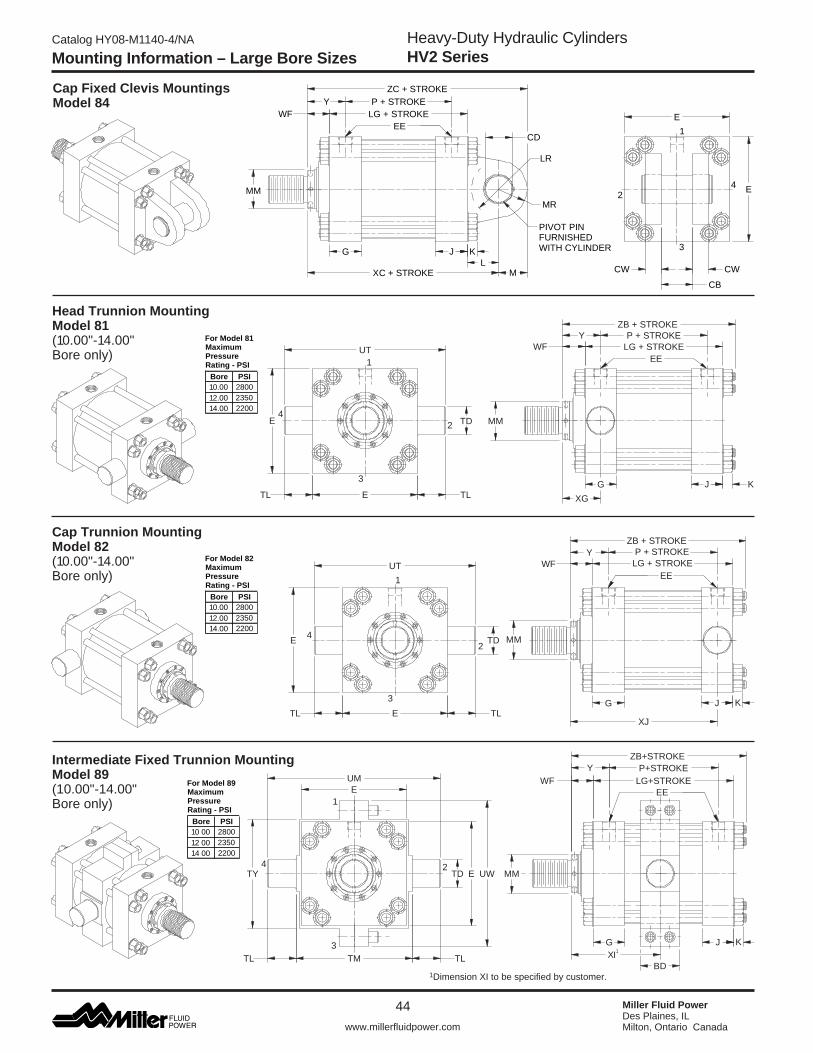
Heavy-Duty Hydraulic CylindersHV2 Series
Catalog HY08-M1140-4/NA
44
www.millerfluidpower.com
Miller Fluid PowerDes Plaines, ILMilton, Ontario Canada
Cap Fixed Clevis Mountings Model 84
Head Trunnion Mounting Model 81(10.00"-14.00" Bore only)
Cap Trunnion Mounting Model 82(10.00"-14.00" Bore only)
Intermediate Fixed Trunnion MountingModel 89 (10.00"-14.00" Bore only)
MM
K
EE
EKORTS+BZ
FW EKORTS+GL
JG
Y EKORTS+P
GX
DTE
LTELT
TU1
2
3
4
WC
BC
WC
E
EMM
NIPTOVIPDEHSINRUF
REDNILYCHTIW
RL
EEEKORTS+GLFW
RM
G J
DC
K
M
EKORTS+CZEKORTS+PY
LEKORTS+CX
1
4
3
2
K
MM
EE
ZB + STROKEP + STROKE
LG + STROKE
JG
FW
JX
Y
DTE
LTELT
TU
1
2
3
4
K
MM
EE
EKORTS+BZ
JG
EKORTS+GLFW
DBI1X
Y EKORTS+P
4
3
2
1
E
LTMTLT
YT DT WU
EMU
1 Dimension XI to be specified by customer.
Maximum Pressure
Bore PSI280023502200
Rating - PSI
For Model 81
10.0012.0014.00
Maximum Pressure
Bore PSI280023502200
Rating - PSI
For Model 82
10.0012.0014.00
Maximum Pressure
Bore PSI280023502200
Rating - PSI
For Model 89
10 0012 0014 00
Mounting Information – Large Bore Sizes

45
www.millerfluidpower.com
Heavy-Duty Hydraulic CylindersHV2 Series
Catalog HY08-M1140-4/NA
Miller Fluid PowerDes Plaines, ILMilton, Ontario Canada
5 Dimension XI to be specified by customer.
6 Consult Factory
Rod End Dimensions — see Table 2
If rod end is not specified, Style 2 will be furnished.
Table 2—Rod DimensionsTable 3—Envelope and Mounting Dimensions
Table 1—Envelope and Mounting Dimensions
MM RDB
NA
V
FWFA
CKK
.515 DIA.x .75 DEEP4 HOLES
Table 4—Optional SAE Flange Port Pattern
Table 5—Tie Rod Information
W
HEADOR CAP
Z HOLESFULL THREADDEPTH AA
A DIA
Q
XGG
RB
10.00", 12.00" Bores14.00" Bore
Table 1A—Envelope and Mounting Dimensions
Thread Style 2(NFPA Style SM) Small Male
Nom. Flange
Size
11/2
2
21/2
3
A
1.50
2.00
2.50
3.00
Q
2.750
3.062
3.500
4.188
GG
1.406
1.688
2.000
2.438
W
1.38
1.53
1.75
2.09
X
0.70
0.84
1.00
1.22
AA Min.
1.06
1.06
1.19
1.19
Z-THD
UNC-2B1/2-131/2-131/2-135/8-11
S.A.E.Flange
Dash Size
-24
-32
-40
-48
18.007 7 7 7
Bore
Tie Rod Thread
RA
RB
RC
10.00
11/8-12
5.291
3.775
—
12.00
11/4-12
6.270
4.555
—
14.00
11/4-12
7.485
6.143
4.409
16.007 7 7 7
20.007 7 7 7
7Consult factory for dimensions
Bore BD CB
+.001 -.003 CD4 CW E
EE1 NPTF
EEf2 SAE FLANGE
PORT
EE3 SAE STR. THD. G J K L LR M MR
+.000 -.001 TD TL TM TY UM UT UW
Add Stroke
LG P
10.00 4.50 4.00 3.500 2.00 12.63 2 2 24 3.69 3.69 1.28 4.00 3.38 3.50 3.50 3.500 3.50 14.00 13.00 21.00 19.63 17.50 12.13 8.50
12.00 5.50 4.50 4.000 2.25 14.88 2 1/2 2 1/2 24 4.44 4.44 1.41 4.50 3.88 4.00 4.00 4.000 4.00 16.50 15.50 24.50 22.88 20.75 14.50 10.13
14.00 5.50 6.00 5.000 3.00 17.13 2 1/2 2 1/2 24 4.88 4.88 1.41 5.75 4.19 5.00 5.00 4.500 4.50 19.50 19.25 28.50 26.13 24.75 15.63 10.88
Bore EEE
(SAE)EE
(FLANGE) CB CD4 CW G J K L LR M MD MR
Add Stroke
LG P
16.00 19.00 24 3 7.00 6.00 3.50 5.88 5.88 1.91 7.00 6.25 6.00 16.00 6.00 18.13 12.13
18.00 22.00 24 3 8.00 6.50 4.00 6.88 6.88 1.91 7.63 6.75 6.50 18.00 6.50 21.13 15.13
20.00 24.00 24 3 9.00 7.50 4.50 7.88 7.88 1.91 8.75 7.75 7.50 20.00 7.50 23.63 17.63
1 NPTF ports are available at no extra charge.2 Optional SAE flange ports may be specified
– flange to be supplied by customer. See Table 4 for flange port pattern dimensions.
3 SAE straight thread ports are standard and are indicated by port number.
4 Dimension CD is pin diameter.
Bore
Rod Dia. MM
Thread KK
Rod Extensions and Pilot Dimensions
XGMin. XI5 Y
Add Stroke
A
+.000 -.005
B C F NA RD V WF XC XJZB
(Max.) ZC
10.00
4.500 3 1/4-12 4.50 5.249 1.00 1.94 4.38 8.25 0.25 2.94 4.75 9.06 4.75 19.06 13.38 16.69 22.56
7.000 5-12 7.00 7.999 1.00 1.94 6.88 10.50 0.38 3.50 5.31 9.63 5.31 19.63 13.94 17.25 23.13
5.000 3 1/2-12 5.00 5.749 1.00 1.94 4.88 8.88 0.25 3.19 5.00 9.31 5.00 19.31 13.63 16.94 22.81
5.500 4-12 5.50 6.249 1.00 1.94 5.38 9.38 0.25 3.19 5.00 9.31 5.00 19.31 13.63 16.94 22.81
12.00
5.500 4-12 5.50 6.249 1.00 1.94 5.38 9.38 0.25 3.19 5.38 10.63 5.38 22.19 15.50 19.44 26.19
8.000 5 3/4-12 8.00 8.999 1.00 1.94 7.88 12.50 0.38 4.00 6.19 11.50 6.19 23.00 16.31 20.25 27.00
7.000 5-12 7.00 7.999 1.00 1.94 6.88 10.50 0.38 3.50 5.69 10.94 5.69 22.50 15.81 19.75 26.50
14.00
7.000 5-12 7.00 7.999 1.00 1.94 6.88 10.50 0.38 3.50 5.94 11.44 5.88 24.88 16.69 20.88 29.88
10.000 7 1/4-12 10.00 10.999 1.00 1.94 9.88 14.50 0.38 4.50 6.94 12.44 6.88 25.88 17.69 21.88 30.88
8.000 5 3/4-12 8.00 8.999 1.00 1.94 7.88 12.50 0.38 4.00 6.44 11.94 6.38 25.38 17.19 21.38 30.38
16.00
8.000 5 3/4-12 8.00 8.999 1.00 1.94 7.88 12.50 0.38 4.00 6 6 7.00 29.13 6 24.38 35.13
9.000 6 1/2-12 9.00 9.999 1.00 1.94 8.88 13.50 0.38 4.25 6 6 7.25 29.38 6 24.63 35.38
10.000 7 1/4-12 10.00 10.999 1.00 1.94 9.88 14.50 0.38 4.50 6 6 7.50 29.63 6 24.88 35.63
18.009.000 6 1/2-12 9.00 9.999 1.00 1.94 8.88 13.50 0.38 4.25 6 6 7.25 33.00 6 27.63 39.50
10.000 7 1/4-12 10.00 10.999 1.00 1.94 9.88 14.50 0.38 4.50 6 6 7.50 33.25 6 27.88 39.75
20.00 10.000 7 1/4-12 10.00 10.999 1.00 1.94 9.88 14.50 0.38 4.50 6 6 7.50 36.88 6 30.38 44.38
Mounting Information – Large Bore Sizes
MM RDB
NA
V
FWF
A
CKK
.515 DIA.x .50 DEEP4 HOLES
Thread Style 4(NFPA Style SF) Small Female
Use Style 4 for applications where female rod ends are required.
Special Thread Style XSpecial thread, extension, rod eye, blank, etc., are also available. To order, specify “Style X” and give desired dimensions for KK, A and WF. If otherwise special, furnish dimensional sketch.
Style 4 stroke restrictions may apply. See Style 4 Minimum Stroke page for details.

Heavy-Duty Hydraulic CylindersHV2 Series
Catalog HY08-M1140-4/NA
46
www.millerfluidpower.com
Miller Fluid PowerDes Plaines, ILMilton, Ontario Canada
How to Use Double Rod Cylinder Dimensioned Drawings
G
SUSW SW
XS SS + STROKE
LG + STROKE
P + STROKE
ZB + STROKE
ZM + 2 x STROKE
EE
WF
KG
MMRD
Y
SU
Dimension Shown on This Page Supplement
Dimensions on Pages Listed Below
36, 37 36, 37 36, 37 38, 39 38, 39 40, 41 42, 43 42, 43
Mounting Styles for Single Rod
Models53525167657281
891
If only one end of these Double Rod Cylinders is to be cushioned, be sure to specify clearly which end this will be.1Specify XI dimension from rod end #1.
To obtain dimensioning information on a double rod cylinder, first select the desired mounting style and refer to the corresponding single rod cylinder model shown on the preceding pages. (See table at left.) After you have determined all necessary dimensions from that drawing, turn back to this page and supplement those dimensions with additional ones from the drawing above and table at right. These added dimensions differ from, or are in addition to, those shown on the preceding pages and provide the additional information needed to completely dimension a double rod cylinder model.On a double rod cylinder where the two rod ends are different, be sure to clearly state which rod end is to be assembled at which end. Port position 1 is standard. If other than standard, specify pos. 2, 3 or 4 when viewed from rod end #1 only. See port position information on ports page.
Mounting Recommendations and Other MountingsIn addition to the standard mountings dimensioned on the preceding pages, the following information covers mounting ideas that may prove helpful in your applications. When needed, special heads, caps, and flanges can be provided. Sketches of your requirements, together with specifications relative to the application and forces involved should be submitted.
Mounting Bolts — High tensile socket head screws are recom-mended for all mounting styles.
Flange Mountings — Cylinders can be properly centered by measuring from piston rod diameter. After mounting, the flange may be drilled for pins or dowels to prevent shifting.
Side Lug Mountings — Caution, cylinders which do not absorb force on their centerline (Group 3) tend to sway when under load. Short stroke, non-centerline mounted cylinders can subject mounting bolts to large tension forces which when combined with shear forces can overstress standard mounting bolts. Side lug mounted cylinders should always be prevented from shifting through use of shear keys so located as to resist the major load, whether push or pull.
Trunnion Mountings — Cylinders require lubricated pillow blocks with minimum bearing clearances. Pillow blocks should be carefully aligned and rigidly mounted so the trunnions will not be subjected to bending moments. The rod end connection should also be pivoted, with the customer’s pin in the piston rod eye parallel to the trunnions.
Clevis Mountings — Cylinders should be pivoted at both ends, with the customer’s pin in the piston rod eye parallel to the pivot pin supplied with the clevis.
Metallic Rod WiperWhen specified, metallic rod wipers can be supplied at extra cost, instead of the standard synthetic rubber wiperseal. Recommended in applications where atmospheric particles or splashings tend to cling to the extended piston rod and otherwise damage the synthetic rubber wiperseal. Installation of metallic rod wiper does not affect cylinder dimensions.
Rod End #1 Rod End #2
Double Rod Models – Large Bore Sizes
Add 2X Stroke
ZM18.0019.1318.5018.5020.8822.5021.5022.6324.6323.6326.1326.6327.1329.6330.1332.63
Bore
10.00
12.00
14.00
16.00
18.00
20.00
Rod Dia.
4.5007.0005.0005.5005.5008.0007.0007.00010.0008.0008.0009.00010.0009.00010.00010.000

47
www.millerfluidpower.com
Heavy-Duty Hydraulic CylindersHV2 Series
Catalog HY08-M1140-4/NA
Miller Fluid PowerDes Plaines, ILMilton, Ontario Canada
M°
TO
TA
LM
OV
EM
EN
T
n Maximum reliability for trouble-free operation, long life and lower operating costsn Increased cylinder life by reducing wear on piston and rod bearings
n Simplifying cylinder installation and reducing assembly costsn Increase rod bearing and rod seal life for lower maintenance costs
How to Order Linear Alignment Couplers — When ordering a cylinder with a threaded male rod end, specify the coupler of equal thread size by part number as listed in Table 1, i.e.; Piston Rod “KK” dimension is 3/4-16, specify coupler part number 1347570075.
Alignment Coupler See Table 1 for Part Numbers and Dimensions
Table 1 — Part Numbers and Dimensions
Linear Alignment Couplers are available in 19 standard thread sizes...Cost Saving Features and Benefits Include...
Linear Alignment Couplers
Part No. A B C D E F G H J K MMax. Pull
Load (lbs.)Approx.
Weight (lbs.)
1347570031 5/16-24 1.13 1.75 0.94 0.50 0.50 0.38 0.75 0.38 0.94 6° 1200 .35
1347570038 3/8-24 1.13 1.75 0.94 0.50 0.50 0.38 0.75 0.38 0.94 6° 2425 .35
1347570044 7/16-20 1.38 2.00 1.13 0.75 0.63 0.50 0.88 0.38 1.09 6° 3250 .55
1347570050 1/2-20 1.38 2.00 1.13 0.75 0.63 0.50 0.88 0.38 1.09 6° 4450 .55
1347570063 5/8-18 1.38 2.00 1.13 0.75 0.63 0.50 0.88 0.38 1.09 6° 6800 .55
1347570075 3/4-16 2.00 2.31 1.63 1.13 0.94 0.75 1.31 0.44 1.28 6° 9050 1.4
1347570088 7/8-14 2.00 2.31 1.63 1.13 0.94 0.75 1.31 0.44 1.28 6° 14450 1.4
1347570100 1-14 3.13 3.00 2.38 1.63 1.44 1.25 1.88 0.75 1.78 6° 19425 4.8
1347570125 1 1/4-12 3.13 3.00 2.38 1.63 1.44 1.25 1.88 0.75 1.78 6° 30500 4.8
1337390125 1 1/4-12 3.50 4.00 2.00 2.00 1.50 1.25 1.69 0.75 2.50 6° 30500 6.9
1337390150 1 1/2-12 4.00 4.38 2.25 2.25 1.75 1.50 1.94 0.88 2.75 10° 45750 9.8
1337390175 1 3/4-12 4.00 4.38 2.25 2.25 1.75 1.50 1.94 0.88 2.75 10° 58350 9.8
1337390188 1 7/8-12 5.00 5.63 3.00 3.00 2.25 1.94 2.63 1.38 3.38 10° 67550 19.8
1337390200 2-12 5.00 5.63 3.00 3.00 2.25 1.94 2.63 1.38 3.38 10° 77450 19.8
1337390225 2 1/4-12 6.75 6.38 3.25 3.50 2.75 2.38 2.88 1.63 3.75 10° 99250 35.3
1337390250 2 1/2-12 7.00 6.50 4.00 3.50 3.25 2.88 3.38 1.63 3.88 10° 123750 45.3
1337390275 2 3/4-12 7.00 6.50 4.00 3.50 3.25 2.88 3.38 1.63 3.88 10° 150950 45.3
1337390300 3-12 7.00 6.50 4.00 3.50 3.25 2.88 3.38 1.63 3.88 10° 180850 45.3
1337390325 3 1/4-12 9.25 8.50 5.25 4.50 4.00 3.38 4.50 2.00 5.50 10° 213450 –
1337390425 4 1/4-12 12.88 11.25 7.75 4.50 5.50 4.88 7.00 1.50 8.75 10° 370850 –

Heavy-Duty Hydraulic CylindersHV2 Series
Catalog HY08-M1140-4/NA
48
www.millerfluidpower.com
Miller Fluid PowerDes Plaines, ILMilton, Ontario Canada
Cylinder AccessoriesMiller offers a complete range of cylinder accessories to assure you of the greatest versatility in present and future cylinder applications.
Rod End Accessories Accessories offered for the rod end of the cylinder include Rod Clevis, Eye Bracket, Rod Eye, Clevis Bracket, and Pivot Pin. To select the proper part number for any desired accessory, refer to the table below or on the opposite page and look in the row to the right of the rod thread in the first column. For economical accessory selection, it is recommended that rod end style 2 be specified on your cylinder order.
Accessory Load Capacity The various accessories have been load rated for your convenience. The load capacity in lbs. is the recom-mended maximum load for that accessory based on a 4:1 design factor in tension. (Pivot Pin is rated in shear.) Before specifying, compare the actual load or the tension (pull) force at maximum operating pressure of the cylinder with the load capacity of the accessory you plan to use. If load or pull force of cylinder exceeds load capacity of accessory, consult factory.
1 Includes pivot pin.2 Cylinder accessory dimensions conform to NFPA recommended standard NFPA/T3.6.8 R1-1984, NFPA recommended standard fluid power systems – cylinder – dimensions for accessories for cataloged square head industrial cylinders.
Part Number
Load Capacity (Lbs.)
Load Capacity (Lbs.)
Shear Capacity (Lbs.)
Part Number
Part Number
5/16-24 05122100001 2600 0740770000 1700 – – 7/16-20 0509400000 4250 0691950000 4100 0683680000 86001/2-20 0509410000 4900 0691950000 4100 0683680000 86003/4-16 0509420000 11200 0691960000 10500 0683690000 193003/4-16 1332840000 11200 0691960000 10500 0683690000 193007/8-14 0509430000 18800 08536100002 20400 0683700000 343001-14 0509440000 19500 08536100002 20400 0683700000 343001-14 1332850000 19500 08536100002 20400 0683700000 34300
1 1/4-12 0509450000 33500 0691980000 21200 0683710000 650001 1/4-12 1332860000 33500 0691980000 21200 0683710000 650001 1/2-12 0509460000 45600 08536200002 49480 0683720000 1052001 3/4-12 0509470000 65600 08536300002 70000 0683730000 1374001 7/8-12 0509480000 65600 08536300002 70000 0683730000 1374002 1/4-12 0509490000 98200 08536400002 94200 0683740000 2147002 1/2-12 0509500000 98200 08536500002 121900 0683750000 3092002 3/4-12 0509510000 98200 08536500002 121900 0683750000 3092003 1/4-12 0509520000 156700 0735380000 57400 0735450000 4209003 1/2-12 0509530000 193200 0735390000 75000 0735470000 565800
4-12 0509540000 221200 0735390000 75000 0735470000 565800
Rod ClevisThread
Size
Pivot PinEye Bracket
Cylinder Accessories

49
www.millerfluidpower.com
Heavy-Duty Hydraulic CylindersHV2 Series
Catalog HY08-M1140-4/NA
Miller Fluid PowerDes Plaines, ILMilton, Ontario Canada
1. Pivot Pins are furnished with Clevis Mounted Cylinders as standard.
2. Pivot Pins are furnished with (2) Retainer Rings.
3. Pivot Pins must be ordered as a separate item if to be used with Rod Eyes, Rod Clevises, or Clevis Brackets.
3 Cylinder accessory dimensions conform to NFPA recommended standard NFPA/T3.6.8 R1-1984, NFPA recommended standard fluid power systems – cylinder – dimensions for accessories for cataloged square head industrial cylinders.
Eye Bracket Dimensions
MR
LR
RE
DD DIA4 HOLES
F
M 25˚
FL
CB
+ .004+ .002
RE
CD 1. When used to mate with the Rod Clevis, select by thread size in table on opposite page.
2. When used to mount the Model 84 Cylinders, select by bore size below.
CBCW CWER
KK THREAD
+.004+.002CD
A
CE
Rod Clevis Dimensions
Pivot Pin Dimensions
CL
CD+.001
.002
1 Includes Pivot Pin2 Consult appropriate cylinder rod end dimensions for compatibility.
Cylinder Accessories
Part Number A CB CD CE CW ER KK Part Number CD CL
05122100001 0.81 0.34 0.313 2.25 0.20 0.30 5/16-24 0683680000 0.500 1.88
0509400000 0.75 0.75 0.500 1.50 0.50 0.50 7/16-20 0683690000 0.750 2.63
0509410000 0.75 0.75 0.500 1.50 0.50 0.50 1/2-20 0683700000 1.000 3.13
0509420000 1.13 1.25 0.750 2.13 0.63 0.75 3/4-16 0683710000 1.375 4.13
1332840000 1.13 1.25 0.750 2.38 0.63 0.75 3/4-16 0683720000 1.750 5.19
0509430000 1.63 1.50 1.000 2.94 0.75 1.00 7/8-14 0683730000 2.000 5.19
0509440000 1.63 1.50 1.000 2.94 0.75 1.00 1-14 0683740000 2.500 6.19
1332850000 1.63 1.50 1.000 3.13 0.75 1.00 1-14 0683750000 3.000 6.25
0509450000 1.88 2.00 1.375 3.75 1.00 1.38 1 1/4-12 0735450000 3.500 8.25
1332860000 2.00 2.00 1.375 4.13 1.00 1.38 1 1/4-12 0735470000 4.000 9.00
0509460000 2.25 2.50 1.750 4.50 1.25 1.75 1 1/2-12
0509470000 3.00 2.50 2.000 5.50 1.25 2.00 1 3/4-12
0509480000 3.00 2.50 2.000 5.50 1.25 2.00 1 7/8-12
0509490000 3.50 3.00 2.500 6.50 1.50 2.50 2 1/4-12
0509500000 3.50 3.00 3.000 6.75 1.50 2.75 2 1/2-12
0509510000 3.50 3.00 3.000 6.75 1.50 2.75 2 3/4-12
0509520000 3.50 4.00 3.500 7.75 2.00 3.50 3 1/4-12
0509530000 4.002 4.50 4.000 8.81 2.25 4.00 3 1/2-12
0509540000 4.002 4.50 4.000 8.81 2.25 4.00 4-12
Part Number CB CD DD E F FL LR M MR R Bore
0740770000 0.31 0.313 0.27 2.25 0.38 1.00 0.63 0.38 0.50 1.75 -
0691950000 0.75 0.500 0.41 2.50 0.38 1.13 0.75 0.50 0.56 1.63 1.50"
0691960000 1.25 0.750 0.53 3.50 0.63 1.88 1.25 0.75 0.88 2.55 2.00", 2.50"
08536100003 1.50 1.000 0.66 4.50 0.88 2.38 1.50 1.00 1.25 3.25 3.25"
0691980000 2.00 1.625 0.66 5.00 0.88 3.00 2.13 1.38 1.63 3.82 4.00"
08536200003 2.50 1.750 0.91 6.50 1.13 3.38 2.25 1.75 2.13 4.95 5.00"
08536300003 2.50 2.000 1.06 7.50 1.50 4.00 2.50 2.00 2.44 5.73 6.00"
08536400003 3.00 2.500 1.19 8.50 1.75 4.75 3.00 2.50 3.00 6.58 7.00"
08536500003 3.00 3.000 1.31 9.50 2.00 5.25 3.25 2.75 3.25 7.50 8.00"
0735380000 4.00 3.500 1.81 12.63 1.69 5.69 4.00 3.50 4.13 9.62 -
0735390000 4.50 4.000 2.06 14.88 1.94 6.44 4.50 4.00 5.25 11.45 -

Heavy-Duty Hydraulic CylindersHV2 Series
Catalog HY08-M1140-4/NA
50
www.millerfluidpower.com
Miller Fluid PowerDes Plaines, ILMilton, Ontario Canada
Accessory Load CapacityThe various accessories have been load rated for your convenience. The load capacity in lbs. is the recom-mended maximum load for that accessory based on a 4:1 design factor in tension. (Pivot Pin is rated in shear.) Before specifying, compare the actual load or the tension (pull) force at the maximum operating pressure of the cylinder with the load capacity of the accessory you plan to use. If load or pull force of cylinder exceeds load capacity of accessory, consult factory.
Rod End Accessories Accessories offered for the rod end of the cylinder include Rod Clevis, Eye Bracket, Rod Eye, Clevis Bracket, and Pivot Pin. To select the proper part number for any desired accessory, refer to the table below or on the opposite page and look in the row to the right of the rod thread in the first column. For economical accessory selection, it is recommended that rod end style 2 be specified on your cylinder order.
1This size supplied with cotter pins.
Part Number
Load Capacity
(Lbs.)Part
Number
Load Capacity
(Lbs.)Part
Number
Shear Capacity
(Lbs.)5/16-24 0740750000 3300 0740760000 3600 0740780000 66007/16-20 0690890000 5000 0692050000 7300 0683680000 86001/2-20 0690900000 5700 0692050000 7300 0683680000 86003/4-16 0690910000 12100 0692060000 14000 0683690000 193003/4-16 0690910000 12100 0692060000 14000 0683690000 193007/8-14 0690920000 13000 0692070000 19200 0683700000 343001-14 0690930000 21700 0692070000 19200 0683700000 343001-14 0690930000 21700 0692070000 19200 0683700000 34300
1 1/4-12 0690940000 33500 0692080000 36900 0683710000 650001 1/4-12 0690940000 33500 0692080000 36900 0683710000 650001 1/2-12 0690950000 45000 0692090000 34000 0683720000 1052001 3/4-12 0690960000 53500 0692100000 33000 0692150000 1374001 7/8-12 0690970000 75000 0692100000 33000 0692150000 1374002 1/4-12 0690980000 98700 0692110000 34900 0683740000 2147002 1/2-12 0690990000 110000 0692120000 33800 0683750000 3092002 3/4-12 0691000000 123300 0692130000 36900 0692160000 3092003 1/4-12 0735360000 161300 0735420000 83500 0735450000 4209003 1/2-12 0734370000 217300 0735420000 83500 0735450000 420900
4-12 0734380000 273800 0735430000 102600 0821810000 5658004 1/2-12 0734390000 308500 0735440000 108400 565800
Rod Eye
Thread Size
Pivot PinClevis Bracket
07354700001
Cylinder Accessories

51
www.millerfluidpower.com
Heavy-Duty Hydraulic CylindersHV2 Series
Catalog HY08-M1140-4/NA
Miller Fluid PowerDes Plaines, ILMilton, Ontario Canada
Rod Eye Dimensions
Pivot Pin Dimensions
CL
CD+.001
.002CB
CDER +.004+.002
CD CA
CD
CDKK THREAD
A FULLTHREAD
Clevis Bracket Dimensions
25˚MR
LR
RE
DD DIA4 HOLES
F
M
FL
CW CWCB
+ .004+ .002
RE
CD
Cylinder accessory dimensions conform to NFPA recommended standard NFPT/T3.6.8 R1-1984, NFPA recommended standard fluid power systems - cylinder - dimensions for accessories for cataloged square head industrial cylinders.
1. Pivot Pins are furnished with Clevis Mounted Cylinders as standard.
2. Pivot Pins are furnished with (2) Retainer Rings.
3. Pivot Pins must be ordered as a separate item if to be used with Rod Eyes, Rod Clevises, or Clevis Brackets.
1This size supplied with cotter pins.
Cylinder Accessories
Part Number A CA CB CD ER KK Part Number CD CL
0740750000 0.75 1.50 0.44 0.438 0.59 5/16-24 0740780000 0.438 1.310690890000 0.75 1.50 0.75 0.500 0.72 7/16-20 0683680000 0.500 1.880690900000 0.75 1.50 0.75 0.500 0.72 1/2-20 0683690000 0.750 2.630690910000 1.13 2.06 1.25 0.750 1.06 3/4-16 0683700000 1.000 3.130690920000 1.13 2.38 1.50 1.000 1.44 7/8-14 0683710000 1.375 4.130690930000 1.63 2.81 1.50 1.000 1.44 1-14 0683720000 1.750 5.190690940000 2.00 3.44 2.00 1.375 1.97 1 1/4-12 0692150000 2.000 5.690690950000 2.25 4.00 2.50 1.750 2.50 1 1/2-12 0683740000 2.500 6.190690960000 2.25 4.38 2.50 2.000 2.84 1 3/4-12 0683750000 3.000 6.250690970000 3.00 5.00 2.50 2.000 2.84 1 7/8-12 0692160000 3.000 6.750690980000 3.50 5.81 3.00 2.500 3.56 2 1/4-12 0735450000 3.500 8.250690990000 3.50 6.13 3.00 3.000 4.25 2 1/2-12 0821810000 4.000 8.630691000000 3.63 6.50 3.50 3.000 4.25 2 3/4-12 07354700001 4.000 9.000735360000 4.50 7.63 4.00 3.500 4.97 3 1/4-120734370000 5.00 7.63 4.00 3.500 4.97 3 1/2-120734380000 5.50 9.13 4.50 4.000 5.69 4-120734390000 5.50 9.13 5.00 4.000 5.69 4 1/2-12
Part Number CB CD CW DD E F FL LR M MR R
0740760000 0.47 0.438 0.38 0.27 2.25 0.38 1.00 0.63 0.38 0.50 1.750692050000 0.75 0.500 0.50 0.41 3.50 0.50 1.50 0.75 0.50 0.63 2.550692060000 1.25 0.750 0.63 0.53 5.00 0.63 1.88 1.19 0.75 0.91 3.820692070000 1.50 1.000 0.75 0.66 6.50 0.75 2.25 1.50 1.00 1.25 4.950692080000 2.00 1.375 1.00 0.66 7.50 0.88 3.00 2.00 1.38 1.66 5.730692090000 2.50 1.750 1.25 0.91 9.50 0.88 3.63 2.75 1.75 2.22 7.500692100000 2.50 2.000 1.50 1.06 12.75 1.00 4.25 3.19 2.25 2.78 9.400692110000 3.00 2.500 1.50 1.19 12.75 1.00 4.50 3.50 2.50 3.13 9.400692120000 3.00 3.000 1.50 1.31 12.75 1.00 6.00 4.25 3.00 3.59 9.400692130000 3.50 3.000 1.50 1.31 12.75 1.00 6.00 4.25 3.00 3.59 9.400735420000 4.00 3.500 2.00 1.81 15.50 1.69 6.69 5.00 3.50 4.13 12.000735430000 4.50 4.000 2.00 2.06 17.50 1.94 7.69 5.75 4.00 4.88 13.750735440000 5.00 4.000 2.00 2.06 17.50 1.94 7.69 5.75 4.00 4.88 13.75

Heavy-Duty Hydraulic CylindersHV2 Series
Catalog HY08-M1140-4/NA
52
www.millerfluidpower.com
Miller Fluid PowerDes Plaines, ILMilton, Ontario Canada
Miller “Style 9” Piston Rod EndSplit Flange Coupling Rod End
n Simplifies alignmentn Reduces assembly timen Allows full rated hydraulic pressure in push and pull directionsn Available in 0.625" through 10.000" piston rod diameters
Style 9 Rod End
Dimensions Style 9 Rod End
See previous catalog pages for B, F, G, RT, VF and VH per bore and rod diameter.
WG G
AD
AE
AM
R 0.06
AF
VF
MM
RT OR FDEPENDINGON MOUNTING
B
VH
“Style 9” Piston Rod End
MM Rod Dia. AD AE AF AM WG
0.625 0.63 0.25 0.38 0.57 1.75
1.000 0.94 0.38 0.69 0.95 2.38
1.375 1.06 0.38 0.88 1.32 2.75
1.750 1.31 0.50 1.13 1.70 3.13
2.000 1.69 0.63 1.38 1.95 3.75
2.500 1.94 0.75 1.75 2.45 4.50
3.000 2.44 0.88 2.25 2.95 5.00
3.500 2.69 1.00 2.50 3.45 5.63
4.000 2.69 1.00 3.00 3.95 5.75
4.500 3.19 1.50 3.50 4.45 6.50
5.000 3.19 1.50 3.88 4.95 6.63
5.500 3.94 1.88 4.38 5.45 7.50
7.000 4.06 2.00 5.75 6.95 8.44
8.000 4.06 2.00 6.50 7.95 8.69
9.000 4.63 2.38 7.25 8.95 8.75
10.000 4.63 2.38 8.00 9.95 9.75

53
www.millerfluidpower.com
Heavy-Duty Hydraulic CylindersHV2 Series
Catalog HY08-M1140-4/NA
Miller Fluid PowerDes Plaines, ILMilton, Ontario Canada
“Style 9” Piston Rod EndSplit Couplers and Weld Plates
WARNING: Piston rod separation from the machine member can result in severe personal injury or even death to nearby personnel. The cylinder user must make sure the weld holding the weld plate to the machine is of sufficient quality and size to hold the intended load. The cylinder user must also make sure the bolts holding split coupler to the weld plate are of sufficient strength to hold the intended load and installed in such a way that they will not become loose during the machine’s operation.
!
Ø E
C D
F BOLTS
Ø A
Ø B
STYLE 9 ROD END
SPLIT COUPLER
WELD PLATE
“Style 9” Piston Rod End
SPLIT WELD ROD BOLT COUPLER PLATE DIA. A B C D E F BOLT SIZE CIRCLE PART NO. PART NO.
0.625 1.50 2.00 .50 .56 .250 4 #10-24 x .94 LG 1.125 1472340062 1481740062 1.000 2.00 2.50 .50 .88 .250 6 .250-20 x 1.25 LG 1.500 1472340100 1481740100 1.375 2.50 3.00 .63 1.00 .250 6 .312-18 x 1.50 LG 2.000 1472340138 1481740138 1.750 3.00 4.00 .63 1.25 .250 8 .312-18 x 1.75 LG 2.375 1472340175 1481740175 2.000 3.50 4.00 .75 1.63 .375 12 .375-16 x 2.25 LG 2.687 1472340200 1481740200 2.500 4.00 4.50 .75 1.88 .375 12 .375-16 x 2.50 LG 3.187 1472340250 1481740250 3.000 5.00 5.50 1.00 2.38 .375 12 .500-13 x 3.25 LG 4.000 1472340300 1481740300 3.500 5.88 7.00 1.00 2.63 .375 12 .625-11 x 3.50 LG 4.687 1472340350 1481740350 4.000 6.38 7.00 1.00 2.63 .375 12 .625-11 x 3.50 LG 5.187 1472340400 1481740400 4.500 6.88 8.00 1.00 3.13 .375 12 .625-11 x 4.00 LG 5.687 1472340450 1481740450 5.000 7.38 8.00 1.00 3.13 .375 12 .625-11 x 4.00 LG 6.187 1472340500 1481740500 5.500 8.25 9.00 1.25 3.88 .375 12 .750-10 x 5.00 LG 6.875 1472340550 1481740550 7.000 10.38 11.00 1.75 4.00 .500 12 1.00-8 x 5.50 LG 8.750 1472340700 1481740700 8.000 11.38 12.00 2.00 4.00 .500 16 1.00-8 x 5.50 LG 9.750 1472340800 1481740800 9.000 13.12 14.00 2.25 4.00 .500 12 1.25-7 x 6.00 LG 11.125 1472340900 1481740900 10.000 14.12 15.00 2.50 4.50 .500 16 1.25-7 x 6.50 LG 12.250 1472341000 1481741000
Table 1 — Part Numbers and Dimensions
Note: Screws are not included with coupler or weld plate.

Heavy-Duty Hydraulic CylindersHV2 Series
Catalog HY08-M1140-4/NA
54
www.millerfluidpower.com
Miller Fluid PowerDes Plaines, ILMilton, Ontario Canada
Push and Pull Forces
Push and Pull ForcesPush Force and Displacement
Cyl.BoreSize
(Inches)1.502.002.503.254.005.006.007.008.0010.0012.0014.0016.0018.0020.00
PistonArea
(Sq. In.)1.7673.144.918.3012.5719.6428.2738.4950.2778.54113.10153.94201.06254.47314.16
Cylinder Push Stroke ForceIn Pounds At Various Pressures
2544791232083144917079621257196428283849502763627854
5088157245415628982141419242513392756557697100531272415708
6511520431954081712771838250232685105735210006130691654120420
80142251393664100615712262307940226283904812315160852035825133
1001773144918301257196428273849502778541131015394201062544731416
250443785
122820753143491070689623
12568196352827538485502656361878540
500885
15702455415062859820141351924525135392705655076970100530127235157080
10001770314049108300
125701964028270384905027078540113100153940201060254470314160
20003540628098201660025140392805654076980100540157080226200307880402120508940628320
3000531094201473024900377105892084810115470150810235620339300461820603180763410942480
Deductions for Pull Force and Displacement
General FormulaThe cylinder output forces are derived from the formula: F = P x A Where F = Force in pounds. P = Pressure at the cylinder in pounds per square inch, gauge. A = Effective area of cylinder piston in square inches.
PistonArea
(Sq. In.).307.7851.492.413.144.917.079.6212.5715.9019.6423.7638.4950.2763.6278.53
PistonRodDia.
(Inches)0.6251.0001.3751.7502.0002.5003.0003.5004.0004.5005.0005.5007.0008.0009.000
10.000
25820376079123177241314398491594962125715901964
5015397512115724535448162879598211881924251331813927
652051971572043194606258171034127715442502326741355105
80256511919325139356677010061272157119013079402150896283
100317914924131449170796212571590196423763849502763627854
2507719637360378512281767240531433976491059409621125661590419635
500154392745120515702455353548106285795298201188019243251333180939270
DisplacementPer InchOf Stroke(Gallons)
.0013
.0034
.0065
.0104
.0136
.0213
.0306
.0416
.0544
.0688
.0850
.1028
.1666
.2176
.2754
.3400
10003077851490241031404910707096201257015904196402376038485502656361778540
2000614
1570298048206280982014140192402514031808392804752076970100530127234157080
3000921
235544707230942014730212102886037710477125892071280115455150795190851235620
Piston Rod Diameter Force In Pounds At Various Pressures
To determine Cylinder Pull Force or Displacement, deduct the following Force orDisplacement corresponding to Rod Size, from selected Push Stroke Force or
Displacement corresponding to Bore Size in table above.
DisplacementPer InchOf Stroke(Gallons)
.00765.0136.0213.0359.0544.0850.1224.1666.2176.3400.4896.6664.87041.10161.3600

55
www.millerfluidpower.com
Heavy-Duty Hydraulic CylindersHV2 Series
Catalog HY08-M1140-4/NA
Miller Fluid PowerDes Plaines, ILMilton, Ontario Canada
Operating Fluids and Temperature Range
Class No.1 StandardNitrile Polyurethane
2 OptionalWater base fluid seal
3 Special (EPR) (At extra cost)
Note: Class 3 seals are not compatible with hydraulic oil.
4 Special (Nitrile) (At extra cost)
5 Optional (At extra cost)(Fluorocarbon Seals)
Note: Class 5 seals are not suitable for use with Skydrol fluid, but can be used with hydraulic oil if desired
6 Optional (HWCF) (At extra cost)
8 Optional (At extra cost) Energized PTFE
Operating Fluids and Temperature RangeFluidpower cylinders are designed for use with pressurized air, hydraulic oil and fire resistant fluids, in some cases special seals are required.
Class 1 SealsClass 1 seals are the standard seals provided in a cylinder assembly. They are intended for use with fluids such as: air, nitrogen, mineral base hydraulic oil or MIL-H-5606 within the temperature range of -10°F (-23°C) to +165°F (+74°C). The individual seals may be nitrile (Buna-N), enhanced polyurethane, polymyte, PTFE or filled PTFE.
Class 2 (Nitrile) SealsClass 2 seals are intended for use with water base fluids within the temperature of -10°F (-23°C) to +165°F (+74°C) except for High Water Content Fluids (HWCF) in which case Class 6 seals should be used. Typical water base fluids compatible with Class 2 seals are: Water, Water-Glycol, Water-in Emulsion, Houghto-Safe 27, 620 5040, Mobil Pyrogard D, Shell Irus 905, Ucon Hydrolube J-4. Class 2 seals are nitrile. Lipseal will have polymyte or PTFE back-up washer when required. O-rings will have nitrile back-up washers when required.
Class 3 Seals — Ethylene Propylene (E.P.R.) SealsClass 3 seals are intended for use with some Phosphate Ester Fluids between the temperatures of -10°F (-23°C) to +130°F (+54°C). Typical fluids compatible with Class 3 seals are Skydrol 500 and 700. Class 3 seals are Ethylene Propylene. Lipseals will have a PTFE back-up washer when required. O-rings will have EPR back-up washers when required. Note: Class 3 seals are not compatible with mineral base hydraulic oil or greases. Even limited exposure to these fluids will cause severe swelling. PTFE back-up washer may not be suitable when used in a radiation environment.
Class 4 Seals — Nitrile SealsClass 4 seals are intended for low temperature service with the same type of fluids as used with Class 1 seals within the temperature range of -50°F (-46°C) to +150°F (+66°C). Class 4 seals are nitrile seals. Lipseals will have leather, polymyte or PTFE back-up washers when required. O-rings will have nitrile back-up washers when required. Note: Certain fluids may react adversely with Class 4 seals compared to Class 1 seals.
Class 5 Seals — Fluorocarbon SealsClass 5 seals are intended for elevated temperature service or for some Phosphate Ester Fluids such as Houghto-Safe 1010, 1055, 1120; Fyrquel 150, 220, 300, 350; Mobil Pyrogard 42, 43, 53, and 55. Note: In addition, Class 5 seals can be used with fluids listed below under Class 1 or Class 2 service. However, they are not compatible with Phosphate Ester Fluids such as Skydrols. Class 5 seals can operate with a temperature range of -10°F (-23°C) to +250°F (+121°C). Fluorocarbon seals may be operated to +400°F (+204°C) with limited service life. For temperatures above +250°F (-121°C) the cylinder must be manufactured with non-studded piston rod thread and a pinned piston to rod connection. Class 5 seals are fluorocarbon seals. Lipseals will have PTFE back-up washers. O-rings will have fluorocarbon back-up when required.
Class 6 SealsClass 6 seals are intended for High Water Content Fluids (HWCF) such as Houghton Hydrolubric 120B and Sonsol Lubrizol within the temperature range of +40°F (+4°C) to +120°F (+49°C). Class 6 seals are special nitrile compound dynamic seals. Lipseals will have PTFE and or polymyte back-up washers when required. O-rings will have nitrile back-up washers when required. Because of the viscosity of these fluids, cylinders specified with Class 6 seals, will also be modified to have lipseal piston seals and straight cushions.
Class 8 Seals – Energized PTFE SealsClass 8 seals consist of PTFE piston lipseals, rod seal and wiperseal. Piston seals have an internal stainless steel spring to energize both the static and dynamic sealing lips. They are intended for high temperature applications, to 400° F (204° C), where longer seal life and improved high temperature sealing performance is required. Body and gland o-ring seals will be fluorocarbon. Fluid resistance is comparable to Class 5.
Hi-Load SealsHi-Load seals consist of one or two filled PTFE dynamic piston seals with an elastomer expander underneath. Hi-Load piston arrangement normally consists of a wear ring on
each end of the piston with the seals in the middle. These types of seals are virtually leak free seals under static conditions and can tolerate high pressure. The wear rings on the piston can also tolerate high side loads. The dynamic portion of the seal is bronze filled PTFE and compatible with all six classes of service. However, carbon filled PTFE will provide better seal life when used with Class 6 fluids. A nitrile expander will be provided unless Class 3 or 5 seals are specified. In those cases the expander will be of EPR or Fluorocarbon respectively. Note: It may be necessary to cycle the piston seals 40 or 50 times before achieving leakage free performance.
Lipseal PistonsLipseals with a back-up washers are standard in HV2 Series cylinders and are often used for hydraulic applications when virtually zero static leakage is required. Lipseals will function properly in these applications when used in conjunction with moderate hydraulic pressures. A high load piston option is recommended when operating at high pressures and especially with large bore hydraulic cylinders.
Warning!The piston rod stud and the piston rod to piston threaded connections are secured with an anaerobic adhesive which is temperature sensitive. Cylinders specified with fluorocarbon seals are assembled with anaerobic adhesive having a maximum temperature rating of +250°F (+121°C). Cylinders specified with all other seal compounds are assembled with anaerobic adhesive have a maximum operating temperature rating +165°F (+74°C). These temperature limitations are necessary to prevent the possible loosening of the threaded connections. Cylinders originally manufactured with Class 1 seals (Nitrile) that will be exposed to ambient temperatures above +165°F (+74°C) must be modified for higher temperature service. Contact the factory immediately and arrange for the piston to rod and the stud to piston rod connections to be properly reassembled to withstand the higher temperature service.
Low Friction Hydraulic SealsLow Friction hydraulic seals are available as an option for both piston and piston rod seals for HV2 Series cylinders. They are sometimes used when a cylinder is controlled by servo or proportional valve. The seal assembly itself is a two piece assembly consist-ing of a filled PTFE dynamic seal with an elastomer expander. A piston seal assembly consists of one seal assembly in the middle of the piston with a filled PTFE wear ring on each side of the piston. The piston rod seal assembly consists of two seal assemblies and an elastomer wiper seal. The filled PTFE seals are compatible with Class 1, 2, 3, 4 & 5 fluids and provide virtually leak free sealing. The expanders and rod wiper will be nitrile unless Class 3 or 5 seals are specified. In those cases the expanders and wiper will be EPR and fluorocarbon respectively. When specifying low friction seals specify if piston, piston rod seals or both are required. Note: It may be necessary to cycle these seals 40 or 50 times before achieving leakage free performance.
Cast Iron Piston RingsCast iron rings are optional piston seals for HV2 Series cylinders. They offer the widest operating conditions by tolerating high operating pressures, wide tempera-ture range and are compatible with most fluids. The only drawback of cast iron rings is that they allow a small amount of leakage. The leakage for a 4" bore cylinder, operating at 2000 psi, with mineral base hydraulic fluid will be less than 10in.3/min. Leakage will increase as pressure, bore size and viscosity of the operating hydraulic fluid increases. For these reasons cast iron rings are not recommended when using water or Class 6 fluids.
Water ServiceHV2 Series hydraulic cylinders can be modified for water operation and supplied with chrome-plated cylinder bore; electroless nickel-plated head, cap and piston; chrome-plated precipitation hardened stainless steel piston rod, chrome-plated cushion plungers. When high water base fluids are the operating medium, hydraulic cylinders are usually supplied with high water base rod wiper and seals. Water and high water base fluid operated cylinders are best used on short stroke applications or where high pressure is applied only to clamp the load.
WarrantyAtlas will warrant cylinders modified for water or high water content fluid service to be free of defects in materials or workmanship, but cannot accept responsibility to premature failure due to excessive wear due to lack of lubricity or where failure is caused by corrosion, electrolysis or mineral deposits within the cylinder.
Temperature Range-10°F (-23°C) to+165°F (+74°C)
-10°F (-23°C) to+165°F (+74°C)
-10°F (-23°C) to+130°F (+54°C)
-50°F (-46°C) to+150°F (+66°C)
See above paragraph on Fluorocarbon sealsfor recommended temperature range.
+40°F (+4°C) to+120°F (+49°C)
-15°F (-26°C) to 400°F (204°C)
Typical FluidsAir, NitrogenHydraulic Oil, Mil-H-5606 Oil
Water, Water-Glycol, HWCF — See Class 6 below.Water-in-Oil Emulsion Houghto-Safe, 271, 620, 5040Mobil Pyrogard D, Shell Irus 905Ucon Hydrolube J-4
Some Phosphate Ester FluidsSkydrol 500, 7000
Low Temperature Air or Hydraulic Oil
High TemperatureHoughto-Safe 1010, 1055, 1120Fryquel 150, 220, 300, 550Mobil Pyrogard 42,43,53,55
Houghton, Hydrolubric 120BSonsol Lubrizol, for other HWCF — consult factory.
See Class 5 Seals

Heavy-Duty Hydraulic CylindersHV2 Series
Catalog HY08-M1140-4/NA
56
www.millerfluidpower.com
Miller Fluid PowerDes Plaines, ILMilton, Ontario Canada
Pressure Ratings / Style 4 Minimum Stroke
0.625
1.000
1.000
1.375
1.750
2.000
2.500
3.000
3.500
4.500
5.500
7.000
8.000
9.000
10.000
2530
2950
2340
2250
2130
2170
2270
2030
2040
2720
2580
2320
2750
2900
2640
1.50
2.00
2.50
3.25
4.00
5.00
6.00
7.00
8.00
10.00
12.00
14.00
16.00
18.00
20.00
3000
3000
3000
3000
3000
3000
3000
3000
3000
3000
3000
3000
3000
3000
3000
Application DataThe proper application of a fluid power cylinder requires consideration of the operating pressure, the fluid medium, the mounting style, the length of stroke, the type of piston rod connection to the load, thrust or tension loading on the
rod, mounting attitude, the speed of stroke, and how the load in motion will be stopped. Information given here provides pressure rating data for HV2 Series hydraulic cylinders.
Pressure RatingsStandard operating fluid — clean, filtered hydraulic oil. Pressure ratings for heavy-duty hydraulic cylinders are shown in the table.
HV2 Series hydraulic cylinders are recommended for pressures to 3000 psi for heavy-duty service with hydraulic oil. The 4:1 design factor ratings shown are based on tensile strength of material and are for standard rod diameter only. The rating is conservative for continuous severe applications. Design factors at other pressures can be calculated from this rating. In addition, mounting styles, stroke, etc., should be considered because of the limiting effect they may have on these ratings.
Bore Size(Inches)
1Applies to all mountings except Models 61, 62, 65, 81, 82, 89.
HV2 Series Hydraulic Cylinders Maximum Pressure Ratings
RodDiameter(Inches)
4:11
Design Factor(Tensile)(PSI)
Heavy-DutyService
(PSI)
Rod End Style 4 Minimum StrokeSufficient clearance must exist between machining for female rod end style 4 and the threaded piston-to-rod connection. This clearance is required to maintain pressure envelope integrity and envelope ratings shown above.
To maintain the required clearance, a minimum stroke is required for some bore and rod combinations. See the table below for minimum stroke requirements. Contact the factory when a style 4 rod end with a stroke shorter than shown in the table is required.
BoreRodDia.
MinimumStroke
1.50 - 4.00 All None
5.00 2.000 None
2.500 1.00
3.000 1.38
3.500 1.63
6.00 2.500 None
3.000 1.38
3.500 1.38
4.000 2.00
7.00 3.000 1.25
3.500 1.50
4.000 1.50
5.000 3.13
8.00 3.500 1.50
4.000 1.50
5.000 2.88
5.500 3.63
BoreRodDia.
MinimumStroke
10.00 4.500 1.13
5.000 1.38
5.500 2.00
7.000 3.13
12.00 5.500 1.25
7.000 2.38
8.000 1.13
14.00 7.000 2.00
8.000 2.75
10.000 4.25
16.00 8.000 1.75
9.000 2.50
10.000 3.25
18.00 9.000 1.50
10.000 2.25
20.00 10.000 1.25

57
www.millerfluidpower.com
Heavy-Duty Hydraulic CylindersHV2 Series
Catalog HY08-M1140-4/NA
Miller Fluid PowerDes Plaines, ILMilton, Ontario Canada
Cylinder Weights
Cylinder Weights
67, 68, 72, 81, 82,84, 87, 89, 94
9.0 9.3
13.2 17.1
19.5 25.5
41.0 46.0
53.0 58.0
82.0 86.0
133.0 140.0
242.0 253.0
276.0 309.0
To determine the net weight of a cylinder, first select the proper basic weight for zero stroke, then calculate the weight of the cylinder stroke and add the result to the basic weight. For extra rod extension use piston rod weights per inch shown in Table B. Weights of cylinders with intermediate
BoreSize
1.50
2.00
2.50
3.25
4.00
5.00
6.00
7.00
8.00
RodDia.
0.625 1.000
1.000 1.375
1.000 1.750
1.375 2.000
1.750 2.500
2.000 3.500
2.500 4.000
3.000 5.000
3.5005.500
50, 51, 52, 53, 61,62, 65, 66, 74
7.8 8.4
11.6 13.5
17.0 22.5
32.0 37.0
48.0 52.0
76.0 88.0
125.0 133.0
233.0 240.0
262.0 300.0
Add Per Inchof Stroke
.5
.6
.8 1.0
1.1 1.5
1.8 2.2
2.5 3.2
3.4 5.2
5.2 7.3
6.7 10.3
9.0 13.0
D50, D51, D53, D61, D65, D74
9.1 9.7
14.6 19.4
21.0 27.0
43.0 48.0
59.0 92.0
96.0 117.0
153.0 182.0
320.0 341.0
323.0 390.0
D67, D72,D81, D87, D89
10.7 10.8
16.8 20.6
24.5 30.0
52.0 57.0
63.0 97.0
102.0 123.0
159.0 190.0
339.0 360.0
331.0411.0
Add Per Inchof Stroke
.6
.8
1.0 1.4
1.3 2.2
2.2 3.1
3.2 4.6
4.8 7.9
6.6 10.9
8.7 15.9
11.719.7
Single Rod CylindersBasic Wt. Zero Stroke
Double Rod CylindersBasic Wt. Zero Stroke
Table A Cylinder Weights, in pounds
rods may be estimated from table below by taking the difference between the piston rod weights per inch and adding it to the standard rod diameter weight for the cylinder bore size involved.
Rod Dia.
0.625
1.000
1.375
1.750
Rod Wt. Per Inch
.89
1.40
2.00
2.72
Table B Piston Rod Weights, in pounds
Rod Dia.
2.000
2.500
3.000
3.500
Rod Dia.
4.000
4.500
5.000
5.500
Rod Wt. Per Inch
.09
.22
.42
.68
Rod Wt. Per Inch
3.56
4.51
5.56
6.72
67, 68, 89
646704
1057 1155
15201681
2073 2181
3165 3224
4231
BoreSize
10.00
12.00
14.00
16.00
18.00
20.00
RodDia.
4.5007.000
5.5008.000
7.00010.000
8.000 10.000
9.000 10.000
10.000
81, 82
562620
924 1022
13351496
N/A
Add Per Inchof Stroke
1521
22 29
2839
35 43
45 50
57
Add to All Mtg. Styles
43101
64 162
101262
149 257
198 257
257
Add Per Inchof Stroke
2032
29 43
3961
49 65
63 72
79
Single Rod CylindersBasic Wt. Zero Stroke
Double Rod CylindersBasic Wt. Zero Stroke
65, 66
684742
1136 1234
15821743
2257 2364
3256 3315
4406
72, 84
607665
1000 1097
14851646
2226 2334
3330 3390
4551
Rod Dia.
7.000
8.000
10.000
Rod Wt. Per Inch
10.89
14.22
22.23

Heavy-Duty Hydraulic CylindersHV2 Series
Catalog HY08-M1140-4/NA
58
www.millerfluidpower.com
Miller Fluid PowerDes Plaines, ILMilton, Ontario Canada
Ports
1
2
3
4
Table BSAE Straight Thread O-Ring Ports
Size Tube Thread Size Tube Thread No. O.D. (In.) Size No. O.D. (In.) Size
Note: For the pressure ratings of individual connectors, contact your connector supplier. Hydraulic cylinders applied with meter out or deceleration circuits are subject to intensified pressure at the cylinder piston rod end. The rod end pressure is approxi-mately equal to: Effective Cap End Piston Area
Effective Rod End Piston Area x Operating Pressure
International PortsOther port configurations to meet international requirements are available at extra cost. Miller HV2 Series cylinders can be supplied, on request, with British standard taper port (BSPT). Such port has a taper of 1 in 16 measured on the diameter (1/16" per inch). The thread form is Whitworth System, and size and number of threads per inch are as follows:
Table CBritish Standard Pipe Threads
British standard parallel internal threads are designated as BSPP and have the same thread form and number of threads per inch as the BSPT type and can be supplied, on request, at extra cost. Unless otherwise specified, the BSPP or BSPT port size supplied will be the same nominal pipe size as the NPTF port for a given bore size cylinder.
Metric ports can also be supplied to order at extra cost. See table below for standard port size for each bore.
1/81/43/81/23/4
111/4
11/2
2
PortsHV2 Series cylinders can be supplied with SAE straight O-ring ports or NPTF pipe thread ports. If specified on your order, extra ports can be provided on the sides of heads or caps that are not occupied by mountings or cushion valve.
Standard port location is position 1 as shown on line drawings in product catalog and Figure 1 below. Cushion adjustment needle and check valves are at positions 2 and 4 (or 3), depending on mounting style. Heads or caps which do not have an integral mounting can be rotated and assembled with ports at 90° or 180° from standard position. Mounting styles on which head or cap can be rotated at no extra charge are shown in Table A below. To order, specify by position number. In such assemblies the cushion adjustment needle and check valve rotate accordingly since their relationship with port position does not change.
Figure 1
Head (Rod) End Head Cap
Table A
Ports can be supplied at positions other than those shown in Table A at an extra charge. To order, specify port position as shown in Figure 1.
Straight Thread PortsThe SAE straight thread O-ring port is recommended for hydraulic applications. Miller will furnish this port configuration at positions shown in Table A. This port can also be provided at positions other than those shown in Table A at an extra charge. SAE port size numbers are listed next to the NPTF pipe thread counterparts for each bore size in the respective product catalogs. Size number, tube O.D., and port thread size for SAE ports are listed in Table B.
Port Position Available
Mounting Style Head End Cap End
51, 52, 53, 61, 62, 65, 66, 87, 89 1, 2, 3 or 4 1, 2, 3 or 4
68, 82, 84, 94 1, 2, 3 or 4 1 or 3
67, 81 1 or 3 1, 2, 3 or 4
72, 74 1 1
0.130.190.250.310.380.500.63
12—16202432—
0.75—
1.001.251.502.00—
11/16 - 12—
15/16 - 1215/8 - 1217/8 - 1221/2 - 12
—
23456810
5/16 - 243/8 - 24
7/16 - 201/2 - 20
9/16 - 183/4 - 167/8 - 14
281919141411111111
.383
.518
.656
.8251.0411.3091.6501.8822.347
Nominal No. Threads Pipe Pipe Size Per Inch O.D.
Table D – Standard Port Sizes
J F BSPT S N SAE Code M R G Bore SAE NPTF 61 Flange ISO 6149 BSPP Metric 1.50 8 1/2 N/A M22 x 1.5 1/2 M22 x 1.5 2.00 8 1/2 N/A M22 x 1.5 1/2 M22 x 1.5 2.50 8 1/2 1/2* M22 x 1.5 1/2 M22 x 1.5 3.25 12 3/4 3/4 M27 x 2 3/4 M27 x 2 4.00 12 3/4 3/4 M27 x 2 3/4 M27 x 2 5.00 12 3/4 3/4 M27 x 2 3/4 M27 x 2 6.00 16 1 1 M33 x 2 1 M33 x 2
J F BSPT S N SAE Code M R G Bore SAE NPTF 61 Flange ISO 6149 BSPP Metric 7.00 20 1 1/4 1 1/4 M42 x 2 1 1/4 M42 x 2 8.00 24 1 1/2 1 1/2 M48 x 2 1 1/2 M48 x 2 10.00 24 1 1/2 2 M48 x 2 1 1/2 M48 x 2 12.00 24 1 1/2 2 1/2 M48 x 2 1 1/2 M48 x 2 14.00 24 1 1/2 1 1/2 M48 x 2 1 1/2 M48 x 2 16.00- 24 – 3 – – – 20.00*Available with 1 inch rod diameter only.

59
www.millerfluidpower.com
Heavy-Duty Hydraulic CylindersHV2 Series
Catalog HY08-M1140-4/NA
Miller Fluid PowerDes Plaines, ILMilton, Ontario Canada
A.50
.75
.75
.75
1.001.251.50
SAEDashNo.8
12
12
12
162024
Flange Ports (Code 61, 3000 psi) SAE 4 Bolt Flange Ports
BoreSize
2.502 3
3.252
4.002
5.002
6.007.008.00
Y2.392.803.173.053.053.423.173.173.423.423.423.523.703.84
W.75
.94
.94
.94
1.031.161.37
Q1.50
1.87
1.87
1.87
2.062.312.75
X.34
.44
.44
.44
.52
.59
.70
AA.81
.75
.75
.75
.871.001.06
SAEDashNo.8
12
12
12
162024
BoreSize2.502
3.252
4.002
5.002
6.007.008.00
Z5/16 - 18
3/8 - 16
3/8 - 16
3/8 - 16
3/8 - 167/16 - 141/2 - 13
GG.69
.87
.87
.87
1.031.191.41
P2.97
3.41
3.66
4.16
4.585.596.31
Ports
Bore EE (NPTF) A (Dia.) B C D P
1.50 3/4 1.38 1.00 0.75 0.78 2.912.00 3/4 1.38 1.00 0.75 0.78 2.912.50 3/4 1.38 1.00 0.75 0.78 3.033.25 1 1.75 1.19 0.91 0.88 3.534.00 1 1.75 1.19 0.91 0.88 3.785.00 1 1.75 1.19 0.91 0.88 4.286.00 1 1/4 2.25 1.31 1.13 1.13 5.137.00 1 1/2 2.50 1.56 1.38 1.38 5.758.00 2 3.00 1.69 1.50 1.50 6.50
Bore EE (SAE) A (Dia.) B C D P
1.50 101 – – – – 2.882.00 101 – – – – 2.882.50 101 – – – – 3.003.25 16 1.75 1.19 0.88 0.88 3.444.00 16 1.75 1.19 0.88 0.88 3.695.00 16 1.75 1.19 0.88 0.88 4.196.00 201 – – – – 5.197.00 241 – – – – 5.508.00 N/A – – – – 6.25
Y
A DIA.
X
GG
P + STROKE
Z UNC-2B THD.AA MIN. DEPTH4 HOLES
QW
Oversize PortsOversize NPTF or SAE straight thread ports can be provided, at an extra charge. For ports one size larger than standard, welded port bosses which protrude from the side of the head or cap are supplied. For dimensions, see drawings and tables below. HV2 Series cylinders equipped with cushions at the cylinder cap end can sustain damage to the cushion check valve (cushion bushing) if excessive oil flow enters the cylinder from the cap end port. Cylinders which are equipped with cap end cushions and ordered with one size oversize ports having hydraulic fluid flow exceeding 25 ft./sec. in the line enter-ing the cap end of the cylinder should be ordered with a “solid cushion” at cap end. All cylinders ordered with double oversize ports should always be ordered with a “solid cushion” at cap end.
1 Port tapped directly into head and cap.
Oversize NPTF Port Boss Dimensions Oversize SAE Straight Thread Port Boss Dimensions
Cylinders which are connected to a meter out flow control with flow entering the cap end of a cylinder provided by an accumulator may also experience damage to the cushion bushing due to high instantaneous fluid flows. This condi-tion can be eliminated by using a meter in flow control or “solid cushions” at cap end.
P + STROKE
EE PORTSIDE
A A
B
C D
2 2.50", 3.25", 4.00" & 5.00" bores cap-flange port not available on Model 66. Model 62 not available at position 2 or 4. Port flange overhangs cap on Model 68.3 2.50" bore head flange port available with 1.000" rod only.

Heavy-Duty Hydraulic CylindersHV2 Series
Catalog HY08-M1140-4/NA
60
www.millerfluidpower.com
Miller Fluid PowerDes Plaines, ILMilton, Ontario Canada
Stroke Data, Stroke Adjusters
STOP PINSEAL FOR THREADS 1" & UP
D-THREADS
J-WRENCH SQUARE
SEAL FOR 1/2& 3/4 THREADSK (MIN.)L
Stroke AdjustersWhere absolute precision in stroke length is required, a screwed adjustable stop can be supplied. Several types are available – the illustration shows a design suitable for infrequent1 adjustment at the uncushioned cap end of a cylinder. Please contact the factory, specifying details of the application and the adjustment required.
Rigidity of Envelope The prestressed tie rod construction of cylinders has advantages in rigidity within the limits of the cylinder tube to resist buckling. For long stroke cylinders within practical limits. Tie rod supports (see table below) which move the tie rod centerlines radially outward are used.
Standard tie rod supports are kept within the envelope dimensions of the head and cap, and generally do not interfere with mounting a long cylinder.
Stroke DataMiller cylinders are available in any practical stroke length. The following information should prove helpful to you in selecting the proper stroke for your cylinder application.
Stroke Tolerances Stroke length tolerances are required due to buildup of tolerances of piston, head, cap and cylinder tube. Stan-dard production stroke tolerances run +.031" to -.015" up to 20" stroke, +.031" to -.20" for 21" to 60" and +.031" to -.031" for greater than 60" stroke. For closer tolerances on stroke length, it is necessary to specify the required tolerance plus the operating pressure and temperature at which the cylinder will operate. Stroke tolerances smaller than .015" are not generally practical due to elasticity of cylinders. If machine design requires such close tolerances, use of a stroke adjuster (below) may achieve the desired result.
Tie Rod Supports
108
2
1
1
—
—
120
2
2
1
1
—
132
3
2
1
1
—
144
3
2
1
1
1
156
3
2
2
1
1
168
4
3
2
1
1
Bore
1.50
2.00
2.50
3.25
4.00
Stroke (Inches) 36
—
—
—
—
—
48
—
—
—
—
—
60
1
—
—
—
—
72
1
1
—
—
—
84
1
1
—
—
—
96
2
1
1
—
—
Nu
mb
er o
fS
up
po
rts
Req
uir
ed
Note: 5.00" through 8.00" bore sizes — no supports required.
1 Infrequent is defined by positioning the retract stroke in a couple of attempts at original machine set-up. The frequent stroke adjuster is recommended when adjustments may be required by the end user.
Bore L Size D J K (Max.) 1.50 1/2 - 20 0.31 0.94 5.00 2.00 3/4 - 16 0.44 1.25 8.00 2.50, 3.25 1 - 14 0.63 1.69 9.00 4.00 11/2 - 12 0.94 2.13 18.00 5.00 2 - 12 1.31 2.69 20.00 6.00 21/2 - 12 1.69 3.13 20.00 7.00 3 - 12 2.00 3.25 20.00 8.00 31/2 - 12 2.38 3.50 20.00

61
www.millerfluidpower.com
Heavy-Duty Hydraulic CylindersHV2 Series
Catalog HY08-M1140-4/NA
Miller Fluid PowerDes Plaines, ILMilton, Ontario Canada
Application and Design Data The spherical bearing life is influenced by many factors, i.e., bearing pressure, load direction oscillating angle and lubrication. The maximum operating pressure ratings of the spherical bearing mountings are based on standard commercial bearing ratings. The 4:1 design factor rating is based on the tensile strength of the material.
The spherical bearings are dimensioned to ensure a satisfactory bearing life under normal operating conditions. The bearing races are made of through-hardened steel and are precision ground. They are phosphate treated and coated with dry film lubricant to minimize friction of contacting surfaces. In the case of a permanent unidirectional load to the bearing, or other unusual operating conditions, the use of a larger bearing may be required.
For longer bearing life, regular lubrication will protect the spherical plain bearing from premature wear and corrosion. Rust-inhibiting EP greases of lithium/lead base, preferably with molybdenum disulphide additives are particularly suited. The radial bearings have lubricating holes and grooves in the races permitting lubrication. The bearing housings at the cap and rod end are provided with grease fittings for lubrication.
Maximum angle of swivel in relation to the center line of the pivot pin is shown as angle a in the table below. It is recommended that this angle is not exceeded when mounting the cylinder.
Mounting Information
Head End Mounting
Cap End Mounting
Recommended maximum swivel angle on each side of the cylinder centerline.
Table 1
Note: Dimension X is the maximum off center mounting of the cylinder. To determine dimension X for various stroke lengths multiply distance between pivot pin holes by tangent of angle a. For extended position use X = XL + 2X stroke.
X
X
XL + STROKE
a
a
XL + STROKE
X
X
a
aHead End Mounted Cap End Mounted
Bore Angle a Tan. of a Angle a Tan. of a
1.50 2.00° 0.035 2.00° 0.035
2.00 2.50° 0.044 4.50° 0.079
2.50 2.50° 0.044 4.50° 0.079
3.25 3.00° 0.052 3.00° 0.052
4.00 2.50° 0.044 3.00° 0.052
5.00 3.00° 0.052 3.00° 0.052
6.00 3.00° 0.052 3.00° 0.052
Spherical Bearing Mount Application

Heavy-Duty Hydraulic CylindersHV2 Series
Catalog HY08-M1140-4/NA
62
www.millerfluidpower.com
Miller Fluid PowerDes Plaines, ILMilton, Ontario Canada
Group 2 PIVOT MOUNTS which absorb force on cylinder centerline.
Heavy-Duty Service For Thrust Loads Models 81, 89 For Tension Loads Models 81, 82, 84, 87, 89Medium-Duty Service For Thrust Loads Model 84 For Tension Loads Model 84
Group 3 FIXED MOUNTS which do not absorb force on the centerline.
Heavy-Duty Service For Thrust Loads Model 72 For Tension Loads Model 72Medium-Duty Service For Thrust Loads Model 74 For Tension Loads Model 74
Stop TubingStop tube is recommended to lengthen the distance between the bushing and piston to reduce bearing loads when the cylinder is fully extended. This is especially true of horizon-tally mounted and long stroke cylinders. Long stroke cylinders achieve additional stability through the use of a stop tube.
Drawing A
When specifying cylinders with long stroke and stop tube, be sure to call out the net stroke and the length of the stop tube. Machine design can be continued without delay by laying in a cylinder equivalent in length to the NET STROKE PLUS STOP TUBE LENGTH, which is referred to as GROSS STROKE.
Drawing B
This design is supplied on all non-cushion cylinders.
Mounting ClassesStandard mountings for fluid power cylinders fall into three basic groups. The groups can be summarized as follows:Group 1 Straight Line Force Transfer with fixed mounts which absorb force on cylinder centerline.Group 2 Pivot Force Transfer. Pivot mountings permit a cylinder to change its alignment in one plane.Group 3 Straight Line Force Transfer with fixed mounts which do not absorb force on cylinder centerline.Because a cylinder’s mounting directly affects the maximum pressure at which the cylinder can be used, the chart below should be helpful in selection of the proper mounting combination for your application. Stroke length, piston rod connection to load, extra piston rod length over standard, etc., should be considered for thrust loads. Alloy steel mounting bolts are recommended for all mounting styles, and thrust keys are recommended for Group 3.
Group 1 FIXED MOUNTS which absorb force on cylinder centerline.
Heavy-Duty Service For Thrust Loads Models 52, 66, 68 For Tension Loads Models 53, 65, 67Medium -Duty Service For Thrust Loads Models 62, 66 For Tension Loads Models 61, 65Light-Duty Service For Thrust Loads Model 62 For Tension Loads Model 61
NET STROKE
(HEAD END)
(PISTON ROD) PISTON
(CAP END)
STOP TUBE
LG + GROSS STROKE
GROSS STROKESTOP TUBE LENGTH
(HEAD END)
(PISTON ROD) PISTON
(CAP END) STOP TUBE
LG + GROSS STROKE
GROSS STROKE
STOP TUBE LENGTHNET
STROKE
Stop Tubing / Mounting Classes

63
www.millerfluidpower.com
Heavy-Duty Hydraulic CylindersHV2 Series
Catalog HY08-M1140-4/NA
Miller Fluid PowerDes Plaines, ILMilton, Ontario Canada
How to Use the ChartThe selection of a piston rod for thrust (push) conditions requires the following steps:1. Determine the type of cylinder mounting style and rod end
connection to be used. Then consult the chart below and find the “stroke factor” that corresponds to the conditions used.
2. Using this stroke factor, determine the “basic length” from the equation:
The graph is prepared for standard rod extensions beyond the face of the rod gland retainers. For rod extensions greater than standard, add the increase to the stroke in arriving at the “basic length.”
3. Find the load imposed for the thrust application by multiplying the full bore area of the cylinder by the system pressure.
4. Enter the graph along the values of “basic length” and “thrust” as found above and note the point of intersection:
A) The correct piston rod size is read from the diagonally curved line labeled “Rod Diameter” next above the point of intersection.
B) The required length of stop tube is read from the right of the graph by following the shaded band in which the point of intersection lies.
C) If required length of stop tube is in the region labeled “consult factory,” submit the following information for an individual analysis:
1) Cylinder mounting style. 2) Rod end connection and method of guiding load. 3) Bore, required stroke, length of rod extension
(Dim. “A” & “WF”) if greater than standard, and series of cylinder used.
4) Mounting position of cylinder. (Note: If at an angle or vertical, specify direction of piston rod.)
5) Operating pressure of cylinder if limited to less than standard pressure for cylinder selected.
WarningPiston rods are not normally designed to absorb bending moments or loads which are perpendicular to the axis of piston rod motion. These additional loads can cause the piston rod end to fail. If these types of additional loads are expected to be imposed on the piston rods, their magnitude should be made known to our Engineering Department so they may be properly addressed. Additionally, cylinder users should always make sure that the piston rod is securely attached to the machine member.
Recommended Mounting Styles for Rod End StrokeMaximum Stroke and Thrust Loads Connection Case Factor
Groups 1 or 3Long stroke cylinders for thrust loads should be mounted using a heavy-duty mounting style at one end, firmly fixed and aligned to take the principal force. Additional mounting should be specified at the opposite end, which should be used for alignment and support. An intermediate support may also be desirable for long stroke cylinders mounted horizontally. See “Tie Rod Supports — Rigidity of Envelope” for a guide. Machine mounting pads can be adjustable for support mountings to achieve proper alignment.
Group 2Model 81 — Trunnion on Head
Models 87 & 89 — Intermediate Trunnion
Model 82 — Trunnion on Cap or Clevis on Cap
Fixed and RigidlyGuided
Pivoted and RigidlyGuided
Supported but not Rigidly Guided
Pivoted and RigidlyGuided
Pivoted and RigidlyGuided
Pivoted and Rigidly Guided
.50
.70
2.00
1.00
1.50
2.00
I
II
III
IV
V
VI
BasicLength
ActualStroke
Stroke Factor
= x
!
Piston Rod Selection Data

Heavy-Duty Hydraulic CylindersHV2 Series
Catalog HY08-M1140-4/NA
64
www.millerfluidpower.com
Miller Fluid PowerDes Plaines, ILMilton, Ontario Canada
100 2 3 4 5 6 7 8 9 1000 2 3 4 5 6 7 8 9 10,000 2 3 4 5 6 7 8 9 100,000 2 310
20
30
40
50
60
300
200
100908070
THRUST–POUNDS
ROD DIAMETER
BA
SIC
LE
NG
TH–I
NC
HE
S
INC
HE
S O
F
STO
P T
UB
E
1
2
34567
CO
NS
ULT
FA
CTO
RY
58
1
134 2 21
2 3 312 4 41
2 5 512
381
Piston Rod — Stroke Selection Chart
1.50" through 8.00" Bore
Piston Rod — Stroke Selection Chart
10.00" through 20.00" Bore
300
200
20
30
40
50
60
708090
100
15,000 2 2.5 3 4 5 6 7 8 9 100,000 2 3 4 5 6 7 8 9
INC
HE
S O
F
STO
P T
UB
E
1
2
34567
CO
NS
ULT
FA
CTO
RY
THRUST-POUNDS
BA
SIC
LE
NG
TH
—IN
CH
ES
ROD DIA.
4 1/2
5 5 1/2 7 8 9 10
Piston Rod Selection Data

65
www.millerfluidpower.com
Heavy-Duty Hydraulic CylindersHV2 Series
Catalog HY08-M1140-4/NA
Miller Fluid PowerDes Plaines, ILMilton, Ontario Canada
Thrust Key MountingsThrust key mountings eliminate the need of using fitted bolts or external keys on side mounted cylinders. Cylinder Models 72 and 74 can be provided with the bushing retainer plate extended below the mounting side of the cylinder (see illustration below). This extended retainer plate can then be fitted into a keyway milled into the mounting surface of the machine member.
Dim. PDModels 72, 74Dim. PADim. FA
.361
.611
.611
.736
.861
.861
.986
.986
Bore1.502.002.503.254.005.006.008.00
+.000" -.001"
W
PD
FA INTEGRAL KEY
PA
Rod Bushing DrainRod bushing drains permit capture of fluid that may accumulate between the primary rod seal and the wiperseal. A 1/8 NPTF port is provided in the bushing retainer or cylinder head (see table below) for connec-tion of plumbing that flows oil back to the reservoir.
1On 5.500” diameter piston rods, with drain in position 2 or 4, the port will be offset 18 degrees clockwise from the position specified.
Drain Port Location
The full square retainer, key retainer, or mounting flange thickness is increased on bore and rod combinations listed in the table at right. The piston rod is extended on 51, 53, 65 and 66 mounts to provide the standard ‘W’ dimension.
Rod Bushing Drain / Thrust Key Mountings
Bore Rod Dia.
50, 52, 62, 66, 68,72 (no key), 74 (no key),81, 82, 84, 87, 89, 94
5153
6165 68
72, 74With Thrust Key Plate
1.500.625 Head Head Head Head Head1.000 Full Retainer Full Retainer Flange Retainer Head Key Retainer
2.001.000 Bolted Retainer Full Retainer Flange Retainer Head Key Retainer1.375 Full Retainer Full Retainer Flange Retainer Head Key Retainer
2.501.000 Bolted Retainer Bolted Retainer Flange Retainer Head Head1.375 Bolted Retainer Bolted Retainer Flange Retainer Head Head1.750 Bolted Retainer Bolted Retainer Flange Retainer Head Key Retainer
3.25 All Bolted Retainer Bolted Retainer Flange Retainer Head Head4.00 All Bolted Retainer Bolted Retainer Head Head Head
5.002.000
– 3.000 Bolted Retainer Bolted Retainer Head Head Head
3.500 Bolted Retainer Bolted Retainer Flange Retainer Head Key Retainer6.00
– 8.00 All1 Bolted Retainer Bolted Retainer Head Head Head
Use of translucent tubing as the drain to reservoir line can provide visual indication of a need for rod seal service when the cylinder bushing is not easily visible within the equipment. Specify rod bushing drain port option and the drain port location, position 1, 2, 3, or 4.
Bore Rod Dia. Retainer or Mounting Flange Thickness
1.50 1.000 0.632.00 1.375 0.752.50 1.750 0.883.25 1.750 & 2.000 0.88
1.441.812.062.632.943.694.255.25
0.190.310.310.380.440.440.500.50

Heavy-Duty Hydraulic CylindersHV2 Series
Catalog HY08-M1140-4/NA
66
www.millerfluidpower.com
Miller Fluid PowerDes Plaines, ILMilton, Ontario Canada
End of Stroke Magnetic Principle Type
Proximity SwitchReliable: Proximity type sensor never contacts cylinder moving parts; eliminating wear and adjustments.
Positive Action: Multiple magnet design provides “snap action.” Eliminates creep and false signals.
Versatile: Sealed stainless steel switch body can be used with any operating fluid and is impervious to most environmental conditions.
OPERATING PRINCIPLE
SensingArea
SensingDistance
Magnet Ass’y Switch Case
N/O
N/C
Com.
Unoperated
N FerrousActuator
DifferentialConnecting Rod
N/O
N/C
Com.
Operated
N
Switch OptionsQuick disconnect.Explosion proof.Sub sea, to 2000 feet depths.Extra-long leads.
As shown in the sketches above, these switches are magnetically operated. Dual magnets provide a dependable “snap action” for positive position sensing.
In the “unoperated” position, the magnet assembly is attracted in the direction of the arrow, causing a finely ground stainless steel connecting rod to hold the contacts open.
In the “operated” position a ferrous part (cushion or piston) enters the sensing area and attracts the magnet assembly which causes the rod to draw the contacts closed.
How to Order:To order switches, enter a “9” in the Modified field of the cylinder model code. Describe the modification in notes by specifying: 1. Magnetic end of stroke switch 2. Installation in head, cap, or both ends of the cylinder 3. Location in the head or cap (position #1, 2, 3, or 4) not occupied by a port or mounting
End-of-Stroke Switch
Bore Rod Dia. HR HB
1.500.625 2.56
3.251.000 2.75
2.001.000 2.56
3.001.375 2.75
2.501.000 2.31
2.751.375 2.501.750 2.75
3.251.375 2.94
2.501.750 3.132.000 3.31
4.001.750 2.88
2.442.000 3.062.500 2.44
5.00
2.000 2.31
3.252.500 2.633.000 2.883.500 3.13
6.00
2.500 2.13
1.443.000 2.383.500 2.634.000 2.88
7.00
3.000 3.38
2.633.500 2.134.000 2.384.500 2.635.000 2.94
8.00
3.500 3.13
2.254.000 3.384.500 3.635.000 2.445.500 2.75
Switch Height
SpecificationsSwitch Type:Magnetic Principle
Contacts: Single Pole-Double Throw (SPDT)
Contact Rating1: 2 Amp at 110-240 VAC (UL & CSA) 100 MA at 12 VDC 50 MA at 24 VDC (CSA)
Note: Check current draw of solenoid valves.
Connection: 36" long, 3 wire, potted in cable. Can be wired Normally Open or Normally Closed. Leads are tagged (Com, N/O, N/C)
Pressure Rating: 3000 PSI Non Shock
Temperature Range: -20°F to + 200°F (UL 104°F. Max.)
Sensing Gap: .030 to .060 inch
Trip Point: Factory Set with Piston Bottomed out
Release Point: Approximately 0.25" Piston Travel
Min. Cyl. stroke 0.50" on 1.50" & 2.00" bore, 0.75" stroke on 2.50" and up.1UL and CSA approved for industrial control, general purpose use. If Class I, Division 1 or 2 is required, please specify.

67
www.millerfluidpower.com
Heavy-Duty Hydraulic CylindersHV2 Series
Catalog HY08-M1140-4/NA
Miller Fluid PowerDes Plaines, ILMilton, Ontario Canada
Parts List / Piston and Rod Assemblies
OPTIONAL RINGTYPE PISTON
48
16
Parts List — 1.50" through 6.00" Bore Sizes
Piston and Rod AssembliesFactory assembled piston and rod assemblies (that include seals for piston type specified) are recommended.
Symbol Description 1 Head 7 Cap 15 Cylinder tube 16 Piston, ring type 17 Piston, lipseal type 18 Cushion plunger, rod head cushion 19 Tie rod 23 Tie rod nut 27 Retainer 37 Piston rod, single rod type 42 Lipseal, piston 44 Back-up washer, piston 47 O-ring, cylinder tube to head and cap seal 48 Piston ring, iron 69 O-ring, cushion adjustment and check valve plug screw 70 Needle, cushion adjustment valve 71 Ball, cushion check valve 72 Plug screw, cushion check valve 73 Bushing, float check, cushion on cap end 74 Retaining ring, float check cushion bushing 118 Piston, Hi-Load type 119 Outer Ring 120 Inner Ring 121 Wear Ring 122 Retainer bolt
147
15
69
72
7473
7
70
17
1837
71
42 44
HI-LOADPISTON
1.50" through 6.00" Bore Sizes

Heavy-Duty Hydraulic CylindersHV2 Series
Catalog HY08-M1140-4/NA
68
www.millerfluidpower.com
Miller Fluid PowerDes Plaines, ILMilton, Ontario Canada
OPTIONAL RINGTYPE PISTON
48 Symbol Description 14 Bushing 40 Rod Wiper 41 Rod Seal 42 Piston Lipseal 43 Rod Seal Back-up Washer 44 Piston Seal Back-up Washer 45 Bushing to head o-ring 47 End seal o-ring 48 Piston ring 62 Bushing kit 119 Outer Ring 120 Inner Ring 121 Wear Ring
Seal Kits See Operating Fluids and Temperature Range Page for compatibility.
HI-LOADPISTON
120
119121
RodSeal Kits
(Contains: 1 EachSym. #40, 41,
& 45)
HV2 KR310 63HV2 KR310 100HV2 KR310 138HV2 KR310 175HV2 KR310 200HV2 KR310 250HV2 KR310 300HV2 KR310 350HV2 KR310 400
lb-ft18 1945 4945 49
120 124131 135312 316528 544
Hi-Load PistonSeal Kits
(Contains: 2 Each Sym.#47, 119, 120 & 121
HV2 KB600 150HV2 KB600 200HV2 KB600 250HV2 KB600 325HV2 KB600 400HV2 KB600 500HV2 KB600 600
Hi-Load PistonSeal Kits
(Contains: 2 EachSym. #47, 119,
120 & 121)
HV2 KB500 150
HV2 KB500 200
HV2 KB500 250
HV2 KB500 325
HV2 KB500 400
HV2 KB500 500
HV2 KB500 600
BronzeBushing Kits(Contains: 1 Each
Sym. #14, 40,41 & 45)
HV2 KR110 63HV2 KR110 100HV2 KR110 138HV2 KR110 175HV2 KR110 200HV2 KR110 250HV2 KR110 300HV2 KR110 350HV2 KR110 400
BoreSize1.502.002.503.254.005.006.00
Tube Seal Kits(Contains: 2 Each
Sym. #47)
HV2 ES200 150HV2 ES200 200HV2 ES200 250HV2 ES200 325HV2 ES200 400HV2 ES200 500HV2 ES200 600
Class 5 FluorocarbonPiston Lipseal
Kits(Contains: 2 Each Sym.
#42, 44 & 47)
HV2 KB200 150HV2 KB200 200HV2 KB200 250HV2 KB200 325HV2 KB200 400HV2 KB200 500HV2 KB200 600
PistonRing Kits
(Contains: 4 Each Sym.#48 & 2 Each Sym. #47)
HV2 KB400 150HV2 KB400 200HV2 KB400 250HV2 KB400 325HV2 KB400 400HV2 KB400 500HV2 KB400 600
BoreSize1.502.002.503.254.005.006.00
Tube Seal Kits(Contains: 2 Each
Sym. #47)
HV2 ES100 150
HV2 ES100 200
HV2 ES100 250
HV2 ES100 325
HV2 ES100 400
HV2 ES100 500
HV2 ES100 600
PistonRing Kits
(Contains: 4 EachSym. #48 & 2 Each
Sym. #47)
HV2 KB300 150
HV2 KB300 200
HV2 KB300 250
HV2 KB300 325
HV2 KB300 400
HV2 KB300 500
HV2 KB300 600
Class 1 & Class 2 Buna-N Tie RodNut
Torque1
RodDia.
0.6251.0001.3751.7502.0002.5003.0003.5004.000
Nodular IronBushing Kits(Contains: 1 Each
Sym. #14, 40,41 & 45)
HV2 KR120 63HV2 KR120 100HV2 KR120 138HV2 KR120 175HV2 KR120 200HV2 KR120 250HV2 KR120 300HV2 KR120 350HV2 KR120 400
Class 1 Polyurethane & Buna-N
Piston LipsealKits
(Contains: 2 EachSym. #42, 44 & 47)
HV2 KB100 150
HV2 KB100 200
HV2 KB100 250
HV2 KB100 325
HV2 KB100 400
HV2 KB100 500
HV2 KB100 600
RodSeal Kits
(Contains: 1 EachSym. #40, 41,
432 & 45)
HV2 KR410 63HV2 KR410 100HV2 KR410 138HV2 KR410 175HV2 KR410 200HV2 KR410 250HV2 KR410 300HV2 KR410 350HV2 KR410 400
BronzeBushing Kits(Contains: 1 Each
Sym. #14, 40,41, 432 & 45)
HV2 KR210 63HV2 KR210 100HV2 KR210 138HV2 KR210 175HV2 KR210 200HV2 KR210 250HV2 KR210 300HV2 KR210 350HV2 KR210 400
RodDia.
Nodular IronBushing Kits(Contains: 1 Each
Sym. #14, 40,41, 432 & 45)
HV2 KR220 63HV2 KR220 100HV2 KR220 138HV2 KR220 175HV2 KR220 200HV2 KR220 250HV2 KR220 300HV2 KR220 350HV2 KR220 400
Class 5 Fluorocarbon
0.6251.0001.3751.7502.0002.5003.0003.5004.000
2Item 43 not required for 0.625" and 1.000" rods.
Parts Identification / Seal Kits
1.50" through 6.00" Bore Sizes
1When assembling cylinder, be sure to torque the tie rods evenly.

69
www.millerfluidpower.com
Heavy-Duty Hydraulic CylindersHV2 Series
Catalog HY08-M1140-4/NA
Miller Fluid PowerDes Plaines, ILMilton, Ontario Canada
Rod Dia.
3.0003.5004.0005.0005.500
Description
BushingRod WiperRod SealRod Seal Back Up WasherEnd Seal Back Up WasherBushing to Head O-Ring
Parts IdentificationSym. No.
144041432645
Sym. No.
474862119120121
Description
End Seal O-RingPiston RingBushing KitOuter RingInner RingWear Ring
Bronze Bushing Kits (Contains: 1 Each
Sym. #14, 40, 41, 45)
Seal Kits See Operating Fluids and Temperature Range Page for compatibility.
HV2-KR110-300HV2-KR110-350HV2-KR110-400HV2-KR110-500HV2-KR110-550
Nodular Iron Bushing Kits
(Contains: 1 Each Sym. #14, 40, 41, 45)
HV2-KR120-300HV2-KR120-350HV2-KR120-400HV2-KR120-500HV2-KR120-550
Rod Seal Kits (Contains: 1 Each Sym. #40, 41, 45)
HV2-KR310-300HV2-KR310-350HV2-KR310-400HV2-KR310-500HV2-KR310-550
Bronze Bushing Kits (Contains: 1 Each
Sym. #14, 40, 41, 43, 45)
HV2-KR210-300HV2-KR210-350HV2-KR210-400HV2-KR210-500HV2-KR210-550
Nodular Iron Bushing Kits
(Contains: 1 Each Sym. #14, 40, 41, 43, 45)
Class 5 ServiceFluorocarbon
HV2-KR220-300HV2-KR220-350HV2-KR220-400HV2-KR220-500HV2-KR220-550
Rod Seal Kits (Contains: 1 Each
Sym. #40, 41, 43, 45)
HV2-KR410-300HV2-KR410-350HV2-KR410-400HV2-KR410-500HV2-KR410-550
Bore Size
7.0008.000
Tube Seal Kits (Contains: 2 Each
Sym. #47)
Class 1 Service Buna-N
HV2-ES100-700HV2-ES100-800
Hi-Load Piston Seal Kits
(Contains: 2 Each Sym. #26, 47 & 121; 1 Each Sym.
#119 & 120)
HV2-KB500-700HV2-KB500-800
Piston Ring Kits (Contains: 4 Each Sym. #48
& 2 Each Sym. #47)
HV2-KB300-700HV2-KB300-800
Tube Seal Kits (Contains: 2 Each
Sym. #47)
HV2-ES200-700HV2-ES200-800
Hi-Load Piston Seal Kits
(Contains: 2 Each Sym. #26, 47 & 121; 1 Each Sym. #119
& 120)
Class 5 ServiceFluorocarbon
HV2-KB600-700HV2-KB600-800
Piston Ring Kits (Contains: 4 Each Sym. #48;
2 Each Sym. #47)
HV2-KB400-700HV2-KB400-800
41 43
40
14
45 2647 47 26
120 119 121
Class 1 ServicePolyurethane & Buna-N
7.00" & 8.00" Bore Sizes
Parts Identification / Seal Kits

Heavy-Duty Hydraulic CylindersHV2 Series
Catalog HY08-M1140-4/NA
70
www.millerfluidpower.com
Miller Fluid PowerDes Plaines, ILMilton, Ontario Canada
10.00" through 20.00" Bore Sizes
Sym. No.
1 Head 7 Cap 15 Cylinder 16 Piston Tube – Ring Type Piston 18 Cushion Sleeve 19 Tie Rod 23 Tie Rod Nut – Non-Locking 26 Back-Up Washer, Cylinder Tube 27 Retainer 37 Piston Rod 40 Wiperseal 41 Rod Seal (Polypak) 43 Back-Up Washer, Polypak 45 O-Ring, Bushing to Head 46A Cushion Sealing Ring 47 O-Ring Cylinder Tube
Sym. No.
48 Piston Ring 55 Piston Lock Pin 69 O-Ring, Cushion Adj. & Check Screws 70 Cushion Adjusting Needle Screw 71 Check Valve Ball 72 Check Valve Screw 117 Rod Bearing 118 Piston – Hi-Load 119 Outer Piston Ring 120 Inner Piston Ring 121 Wear Ring 122 Retainer Bolt 123 Washer, Tie Rod Nut 136 Spacer, Cushion 137 Cushion Spear, Detachable 138 Bolt, Cushion Spear
138122 71 69
40
43
41
27117 45 1 26 47 15 37 18 46A 55 47 26 7 123 23
72 19 136 137 7069
118 121 119 120
Parts Identification

71
www.millerfluidpower.com
Heavy-Duty Hydraulic CylindersHV2 Series
Catalog HY08-M1140-4/NA
Miller Fluid PowerDes Plaines, ILMilton, Ontario Canada
Optional Cast IronPiston Ring Kit
Operating fluids and temperature range – Fluidpower cylinders are designed for use with pressurized air, hydraulic oil and fire resistant fluids, in some cases special seals are required.
Buna-NBuna-N seals are supplied on all standard pneumatic and hydraulic cylinders. They are suitable for use with pressured air, nitrogen, hydraulic oil, water-in oil emulsions or water glycol fluids. The recommended operating temperature range for Buna-N seals is -10°F. (-23°C.) to +165°F (+74°C.).
Fluorocarbon sealsFluorocarbon seals can be supplied, on request, and are especially suitable for some fire resistant fluids as shown in the table on page 57 or for elevated temperature service.
When using Fluorocarbon seals for high temperature service or fluid compatibility within a temperature range of -10°F. (-23°C) to +250°F. (+121°C) specify Class 5 seals.
For elevated temperature service above +250°F. (+121°C) specify Class 5 seals. Class 5 seals can operate up to a maximum of +400°F. (+204°C) with reduced service life.
4816
Rod Gland and Rod Seal Kits
Piston Seal Kits
10.00" through 20.00" Bore Sizes
Parts Identification / Seal Kits
Rod Dia.
Class 1 Polyurethane & Buna-N Class 5 Service Fluorocarbon Retainer Bolt Torque
(Torque values are for bolts installed with lubrication.)
Rod Gland Kits (Contains: 1 Each
Sym. #40, 41, 43, 45 & 117)
Rod Seal Kits (Contains: 1 Each
Sym. #40, 41, 43, & 45)
Rod Gland Kits (Contains: 1 Each Sym. #40, 41, 43,
45 & 117)
Rod Seal Kits (Contains: 1 Each
Sym. #40, 41, 43 & 45)
4.500 HV2-KR125-450 HV2-KR315-450 HV2-KR225-450 HV2-KR415-450 100-105 lb-ft
5.000 HV2-KR125-500 HV2-KR315-500 HV2-KR225-500 HV2-KR415-500 185-194 lb-ft
5.500 HV2-KR125-550 HV2-KR315-550 HV2-KR225-550 HV2-KR415-550 185-194 lb-ft
7.000 HV2-KR125-700 HV2-KR315-700 HV2-KR225-700 HV2-KR415-700 100-105 lb-ft
8.000 HV2-KR125-800 HV2-KR315-800 HV2-KR225-800 HV2-KR415-800 330-346 lb-ft
9.000 HV2-KR125-900 HV2-KR315-900 HV2-KR225-900 HV2-KR415-900 330-346 lb-ft
10.000 HV2-KR125-1000 HV2-KR315-1000 HV2-KR225-1000 HV2-KR415-1000 330-346 lb-ft
Bore Size
Class 1 & 2 Buna-N Class 5 Fluorocarbon
Tie Rod Nut Torque1 Piston Ring Kits
(Contains: 4 Each Sym. #48 & 2 Each
Sym. #47 & 26)
Hi-Load Piston Seal Kits
(Contains: 2 Each Sym. #47 & 121
1 Each Sym. #119 & 120)
PolyPak Piston Seal Kits
(Contains: 2 Each Sym. #42, 44, & 47)
Piston Ring Kits (Contains: 4 Each
Sym. #48 & 2 Each Sym. #47)
Hi-Load Piston Seal Kits
(Contains: 2 Each Sym. #47 & 121
1 Each Sym. #119 & 120)
10.00 HV2-KB300-1000 HV2-KB500-1000 HV2-KB700-1000 HV2-KB400-1000 HV2-KB600-1000 700-716 lb-ft12.00 HV2-KB300-1200 HV2-KB500-1200 HV2-KB700-1200 HV2-KB400-1200 HV2-KB600-1200 1320-1336 lb-ft14.00 HV2-KB300-1400 HV2-KB500-1400 HV2-KB700-1400 HV2-KB400-1400 HV2-KB600-1400 1000-1016 lb-ft16.00
- 20.00Consult Factory 2900-3000 lb-ft
1 When assembling the cylinder, be sure to torque the tie rods evenly.

Heavy-Duty Hydraulic CylindersHV2 Series
Catalog HY08-M1140-4/NA
72
www.millerfluidpower.com
Miller Fluid PowerDes Plaines, ILMilton, Ontario Canada
How to Order HV2 Series CylindersData Required On All Cylinder Orders
When ordering HV2 Series cylinders, be sure to specify each of the following requirements:(NOTE: – Duplicate cylinders can be ordered by giving the SERIAL NUMBER from the original cylinder. Factory records supply a quick, positive identification.)
a) Series Designation (“HV2”)
b) Mounting Model Specify your choice of mounting – as shown and dimensioned in this catalog.
c) Bushing Style “B” or “R” – Bronze “I” or “N” – Iron
d) Piston Rod End Thread Style Call out thread style number. Thread style 2 will be furnished if not otherwise supplied. For special rod ends specify style “X” as indicated below.
e) Cushions (if required) Specify “Cushion-head end,” “Cushion-cap end” or “Cushion-both ends” as required. If cylinder is to have a double rod and only one cushion is required, be sure to specify clearly which end of the cylinder is to be cushioned.
f) Bore Size
g) Length of Stroke
h) Piston Rod Diameter Call out rod diameter. In HV2 Series cylinders, standard rod diameters will be furnished if not otherwise specified, unless length of stroke makes the application questionable.
i) Ports SAE straight thread is standard.
j) Port Locations
k) Seals
l) Modifications Any modifications that are not identified in the cylinder number shown on the following page should be added to the specifications. These can include special fluids, special seals, air bleeds, double rod cylinder with different rod end styles and diameters. For further information consult factory.
Service PolicyWhen cylinders are returned to the factory for repairs, it is standard policy for Miller Fluid Power to make such part replacements as will put the cylinder in as good as new condition. Should the condition of the returned cylinder be such that expenses for repair exceed the cost of a new one, you will be notified.
Certified DimensionsMiller Fluid Power guarantees that all cylinders ordered from this catalog will be built to dimensions shown. All dimensions are certified to be correct, and thus it is not necessary to request certified drawings.
Style X Rod EndA style X rod end indicates a special rod end configuration. All special rod ends must be described by at least all three: KK; A; or W/WF specified with the rod fully retracted. A sketch or drawing should be submitted for rod ends requiring special machining such as snap ring grooves, keyways,
tapers, multiple diameters, etc. It is good design practice to have this machining done on a diameter at least 0.065 inches smaller than the piston rod diameter. This allows the piston rod to have a chamfer preventing rod seal damage during assembly or maintenance.
Model Numbers

73
www.millerfluidpower.com
Heavy-Duty Hydraulic CylindersHV2 Series
Catalog HY08-M1140-4/NA
Miller Fluid PowerDes Plaines, ILMilton, Ontario Canada
How to Order – Example: HV2 72B2N-04.00-8.000-0175 S11T-0
1 10.00"-20.00" bore must only use 'I' bolted iron bushing.2 The number 9 refers to special options or modifications that deviate from the standard product offering.
Non-standard modifications and options not identified in the cylinder model number should be added in the notes when placing an order.
Modifications which can be placed under the designator “9” are as follows:• End-of-Stroke Switches – EPS-5, EPS-6, EPS-7, CLS-1, CLS-4 Styles (See bulletin M0840-B11) – Magnetic Principle Threaded Body Style• Special Port Threads• Cushion Location• Special Mounts• Key Retainer• Bushing Wear Ring (Bronze Bushing only)• Bushing Drain• Multiple Ports
Note: The standard #1 port location is at the top of the cylinder, and the standard cushion adjustment screw is in position #2 when facing the rod end of the cylinder. If multiple ports are required, the last number of the part number should be “9”, indicating modified and the desired port location specified in the notes.
Head CapEnd End
1 12 23 34 4
(Std.)
HV2 72 B 2 N - 04.00 - 8.000 - 0175 S 1 1 T - 0
Mounting Rod End Bore Rod Port PortSeries Style Bushing Style Cushions Dia. Stroke Dia. Type Location Seals Modified
HV2DHV2(D =Dbl.
Rod End)
B =BoltedBronze
R =Retainer
HeldBronze
I =BoltedIron1
N =Retainer
HeldIron
2(Standard)
45
9X
(Special)
R =Rod End
CushionedC =
Cap EndCushioned
B =Both EndsCushioned
N =Non-
Cushioned
S =SAEN =
NPTFF =SAE
FLANGECODE 61
M =ISO 6149
J =BSPTR =
BSPPG =
METRICX =
SPECIAL(SPECIFY)
0 =Standard
92 =Modified
T =Standard
(Class 1 Seals)
V =Fluorocarbon
Seals(Class 5 Seals)
E =Fluorocarbon
Rod Seal,Rod Wiper &
Bushing O-Ring
J =H.W.C.F.
(Class 6 Seals)
W =Water ServiceH = EnergizedPTFE Seals
(Class 8 Seals)(1.50"-8.00"
bore & 1.000"-5.500" rod only)
52, 62, 66,68, 72, 74,
Rod 81, 82, 84,Bore Dia. 89, 94 51, 53 61, 65 67
1.500.625 B R R B
R R R B
2.00 B R R B1.375 R R R B
B B B B2.50 1.375 B B B B
1.750 B B R B1.375 B B B B
3.25 1.750 B B B BB B B B
1.750 B B B BB B B B
2.500 B B B BB B B B
5.002.500 B B B B
B B B B3.500 B B R B2.500 B B B B
6.00B B B B
3.500 B B B BB B B BB B B B
7.003.500 B B B B
B B B BB B B B
3.500 B B B B
8.00B B B BB B B B
5.500 B B B B
4.00
1.000
1.000
1.000
2.000
2.000
2.000
3.000
3.000
4.0003.000
4.0005.000
4.0005.000
ALL10.0020.00
I I I I
Bolted & Full Plate Retainer Held Bushing
Rod Bushing ConstructionB = Bolted Iron or Bronze BushingR = Retainer Held Iron or Bronze Bushing I = Bolted Iron Only Bushing
How To Order

Heavy-Duty Hydraulic CylindersHV2 Series
Catalog HY08-M��40-4/NA
74www.millerfluidpower.com
Miller Fluid PowerDes Plaines, ILMilton, Ontario Canada
Cylinder Safety Guide
Before selecting or using Parker Hannifin Corporation (the Company) cylinders or related accessories, it is important that you read, understand and follow the following safety information. Training is advised before selecting and using the Company’s products.
1.0 General Instructions 1.1 Scope – This safety guide provides instructions for selecting and using
(including assembling, installing, and maintaining) cylinder products. This safety guide is a supplement to and is to be used with the specific Company publications for the specific cylinder products that are being considered for use.
1.2 Fail Safe – Cylinder products can and do fail without warning for many reasons. All systems and equipment should be designed in a fail-safe mode so that if the failure of a cylinder product occurs people and property won’t be endangered.
1.3 Distribution – Provide a free copy of this safety guide to each person responsible for selecting or using cylinder products. Do not select or use the Company’s cylinders without thoroughly reading and understanding this safety guide as well as the specific Company publications for the products considered or selected.
1.4 User Responsibility – Due to very wide variety of cylinder applications and cylinder operating conditions, the Company does not warrant that any particular cylinder is suitable for any specific application. This safety guide does not analyze all technical parameters that must be considered in select-ing a product. The hydraulic and pneumatic cylinders outlined in this catalog are designed to the Company’s design guidelines and do not necessarily meet the design guideline of other agencies such as American Bureau of Shipping, ASME Pressure Vessel Code etc. The user, through its own analysis and testing, is solely responsible for:
• Making the final selection of the cylinders and related accessories. • Determining if the cylinders are required to meet specific design require-
ments as required by the Agency(s) or industry standards covering the design of the user’s equipment.
• Assuring that the user’s requirements are met, OSHA requirements are met, and safety guidelines from the applicable agencies such as but not limited to ANSI are followed and that the use presents no health or safety hazards.
• Providing all appropriate health and safety warnings on the equipment on which the cylinders are used.
1.5 Additional Questions – Call the appropriate Company technical service department if you have any questions or require any additional information. See the Company publication for the product being considered or used, or call �-847-298-2400, or go to www.parker.com, for telephone numbers of the appropriate technical service department.
2.0 Cylinder and Accessories Selection 2.1 Seals – Part of the process of selecting a cylinder is the selection of
seal compounds. Before making this selection, consult the “seal information page(s)” of the publication for the series of cylinders of interest.
The application of cylinders may allow fluids such as cutting fluids, wash down fluids etc. to come in contact with the external area of the cylinder. These fluids may attack the piston rod wiper and or the primary seal and must be taken into account when selecting and specifying seal compounds.
Dynamic seals will wear. The rate of wear will depend on many operating factors. Wear can be rapid if a cylinder is mis-aligned or if the cylinder has been improperly serviced. The user must take seal wear into consideration in the application of cylinders.
2.2 Piston Rods – Possible consequences of piston rod failure or separation of the piston rod from the piston include, but are not limited to are:
• Piston rod and or attached load thrown off at high speed. • High velocity fluid discharge. • Piston rod extending when pressure is applied in the piston
retract mode.
Piston rods or machine members attached to the piston rod may move suddenly and without warning as a consequence of other conditions occurring to the machine such as, but not limited to:
• Unexpected detachment of the machine member from the piston rod.
• Failure of the pressurized fluid delivery system (hoses, fittings, valves, pumps, compressors) which maintain cylinder position.
• Catastrophic cylinder seal failure leading to sudden loss of pressurized fluid.
• Failure of the machine control system. Follow the recommendations of the “Piston Rod Selection Chart and Data”
in the publication for the series of cylinders of interest. The suggested piston rod diameter in these charts must be followed in order to avoid piston rod buckling.
Piston rods are not normally designed to absorb bending moments or loads which are perpendicular to the axis of piston rod motion. These additional loads can cause the piston rod to fail. If these types of additional loads are expected to be imposed on the piston rod, their magnitude should be made known to our engineering department.
The cylinder user should always make sure that the piston rod is securely attached to the machine member.
On occasion cylinders are ordered with double rods (a piston rod extended from both ends of the cylinder). In some cases a stop is threaded on to one of the piston rods and used as an external stroke adjuster. On occasions spacers are attached to the machine member connected to the piston rod and also used as a stroke adjuster. In both cases the stops will create a pinch point and the user should consider appropriate use of guards. If these external stops are not perpendicular to the mating contact surface, or if debris is trapped between the contact surfaces, a bending moment will be placed on the piston rod, which can lead to piston rod failure. An external stop will also negate the effect of cushioning and will subject the piston rod to impact loading. Those two (2) conditions can cause piston rod failure. Internal stroke adjusters are available with and without cushions. The use of external stroke adjusters should be reviewed with our engineering department.
The piston rod to piston and the stud to piston rod threaded connections are secured with an anaerobic adhesive. The strength of the adhesive decreases with increasing temperature. Cylinders which can be exposed to tempera-tures above +250°F (+�2�°C) are to be ordered with a non studded piston rod and a pinned piston to rod joint.
2.3 Cushions – Cushions should be considered for cylinder applications when the piston velocity is expected to be over 4 inches/second.
Cylinder cushions are normally designed to absorb the energy of a linear applied load. A rotating mass has considerably more energy than the same mass moving in a linear mode. Cushioning for a rotating mass application should be reviewed by our engineering department.
2.4 Cylinder Mountings – Some cylinder mounting configurations may have certain limitations such as but not limited to minimum stroke for side or foot mounting cylinders or pressure de-ratings for certain mounts. Carefully review the catalog for these types of restrictions.
Always mount cylinders using the largest possible high tensile alloy steel socket head cap screws that can fit in the cylinder mounting holes and torque them to the manufacturer’s recommendations for their size.
2.5 Port Fittings – Hydraulic cylinders applied with meter out or decelera-tion circuits are subject to intensified pressure at piston rod end.
The rod end pressure is approximately equal to:
operating pressure x effective cap end area effective rod end piston area
Contact your connector supplier for the pressure rating of individual connectors.
3.0 Cylinder and Accessories Installation and Mounting 3.1 Installation 3.1.1 – Cleanliness is an important consideration, and cylinders are
shipped with the ports plugged to protect them from contaminants enter-ing the ports. These plugs should not be removed until the piping is to be installed. Before making the connection to the cylinder ports, piping should be thoroughly cleaned to remove all chips or burrs which might have resulted from threading or flaring operations.
Safety Guide for Selecting and Using Hydraulic, Pneumatic Cylinders and Their Accessories
WARNING: FAILURE OF THE CYLINDER, ITS PARTS, ITS MOUNTING, ITS CONNECTIONS TO OTHER OBJECTS, OR ITS CONTROLS CAN RESULT IN: • Unanticipated or uncontrolled movement of the cylinder or objects connected to it. • Falling of the cylinder or objects held up by it. • Fluid escaping from the cylinder, potentially at high velocity.THESE EVENTS COULD CAUSE DEATH OR PERSONAL INJURY BY, FOR EXAMPLE, PERSONS FALLING FROM HIGH LOCATIONS, BEING CRUSHED OR STRUCK BY HEAVY OR FAST MOVING OBJECTS, BEING PUSHED INTO DANGEROUS EQUIPMENT OR SITUATIONS, OR SLIPPING ON ESCAPED FLUID.

75www.millerfluidpower.com
Heavy-Duty Hydraulic CylindersHV2 Series
Catalog HY08-M��40-4/NA
Miller Fluid PowerDes Plaines, ILMilton, Ontario Canada
Cylinder Safety Guide
3.1.2 – Cylinders operating in an environment where air drying materials are present such as fast-drying chemicals, paint, or weld splatter, or other hazardous conditions such as excessive heat, should have shields installed to prevent damage to the piston rod and piston rod seals.
3.1.3 – Proper alignment of the cylinder piston rod and its mating component on the machine should be checked in both the extended and retracted positions. Improper alignment will result in excessive rod gland and/or cylinder bore wear. On fixed mounting cylinders attaching the pis-ton rod while the rod is retracted will help in achieving proper alignment.
3.1.4 – Sometimes it may be necessary to rotate the piston rod in order to thread the piston rod into the machine member. This operation must always be done with zero pressure being applied to either side of the piston. Failure to follow this procedure may result in loosening the piston to rod-threaded connection. In some rare cases the turning of the piston rod may rotate a threaded piston rod gland and loosen it from the cylinder head. Confirm that this condition is not occurring. If it does, re-tighten the piston rod gland firmly against the cylinder head.
For double rod cylinders it is also important that when attaching or detaching the piston rod from the machine member that the torque be applied to the piston rod end of the cylinder that is directly attaching to the machine member with the opposite end unrestrained. If the design of the machine is such that only the rod end of the cylinder opposite to where the rod attaches to the machine member can be rotated, consult the factory for further instructions.
3.2 Mounting Recommendations 3.2.1 – Always mount cylinders using the largest possible high tensile
alloy steel socket head screws that can fit in the cylinder mounting holes and torque them to the manufacturer’s recommendations for their size.
3.2.2 – Side-Mounted Cylinders – In addition to the mounting bolts, cylinders of this type should be equipped with thrust keys or dowel pins located so as to resist the major load.
3.2.3 – Tie Rod Mounting – Cylinders with tie rod mountings are recom-mended for applications where mounting space is limited. The standard tie rod extension is shown as BB in dimension tables. Longer or shorter extensions can be supplied. Nuts used for this mounting style should be torqued to the same value as the tie rods for that bore size.
3.2.4 – Flange Mount Cylinders – The controlled diameter of the rod gland extension on head end flange mount cylinders can be used as a pilot to locate the cylinders in relation to the machine. After align-ment has been obtained, the flanges may be drilled for pins or dowels to prevent shifting.
3.2.5 – Trunnion Mountings – Cylinders require lubricated bearing blocks with minimum bearing clearances. Bearing blocks should be carefully aligned and rigidly mounted so the trunnions will not be subjected to bending moments. The rod end should also be pivoted with the pivot pin in line and parallel to axis of the trunnion pins.
3.2.6 – Clevis Mountings – Cylinders should be pivoted at both ends with centerline of pins parallel to each other. After cylinder is mounted, be sure to check to assure that the cylinder is free to swing through its working arc without interference from other machine parts.
4.0 Cylinder and Accessories Maintenance, Troubleshooting and Replacement
4.1 Storage – At times cylinders are delivered before a customer is ready to install them and must be stored for a period of time. When storage is required the following procedures are recommended.
4.1.1 – Store the cylinders in an indoor area which has a dry, clean and noncorrosive atmosphere. Take care to protect the cylinder from both internal corrosion and external damage.
4.1.2 – Whenever possible cylinders should be stored in a vertical posi-tion (piston rod up). This will minimize corrosion due to possible conden-sation which could occur inside the cylinder. This will also minimize seal damage.
4.1.3 – Port protector plugs should be left in the cylinder until the time of installation.
4.1.4 – If a cylinder is stored full of hydraulic fluid, expansion of the fluid due to temperature changes must be considered. Installing a check valve with free flow out of the cylinder is one method.
4.1.5 – When cylinders are mounted on equipment that is stored outside for extended periods, exposed unpainted surfaces, e.g. piston rod, must be coated with a rust-inhibiting compound to prevent corrosion.
4.2 Cylinder Trouble Shooting
4.2.1 – External Leakage 4.2.1.1 – Rod seal leakage can generally be traced to worn or
damaged seals. Examine the piston rod for dents, gouges or score marks, and replace piston rod if surface is rough.
Rod seal leakage could also be traced to gland wear. If clearance is excessive, replace rod bushing and seal. Rod seal leakage can also be traced to seal deterioration. If seals are soft or gummy or brittle, check compatibility of seal material with lubricant used if air cylinder, or operating fluid if hydraulic cylinder. Replace with seal material, which is compatible with these fluids. If the seals are hard or have lost elasticity, it is usually due to exposure to temperatures in excess of �65°F. (+74°C). Shield the cylinder from the heat source to limit temperature to 350°F. (+�77°C.) and replace with fluorocarbon seals.
4.2.1.2 – Cylinder body seal leak can generally be traced to loose tie rods. Torque the tie rods to manufacturer’s recommendation for that bore size.
Excessive pressure can also result in cylinder body seal leak. Determine maximum pressure to rated limits. Replace seals and retorque tie rods as in paragraph above. Excessive pressure can also result in cylinder body seal leak. Determine if the pressure rating of the cylinder has been exceeded. If so, bring the operating pressure down to the rating of the cylinder and have the tie rods replaced.
Pinched or extruded cylinder body seal will also result in a leak. Replace cylinder body seal and retorque as in paragraph above.
Cylinder body seal leakage due to loss of radial squeeze which shows up in the form of flat spots or due to wear on the O.D. or I.D. – Either of these are symptoms of normal wear due to high cycle rate or length of service. Replace seals as per paragraph above.
4.2.2 – Internal Leakage 4.2.2.1 – Piston seal leak (by-pass) � to 3 cubic inches per minute
leakage is considered normal for piston ring construction. Virtually no static leak with lipseal type seals on piston should be expected. Piston seal wear is a usual cause of piston seal leakage. Replace seals as required.
4.2.2.2 – With lipseal type piston seals excessive back pressure due to over-adjustment of speed control valves could be a direct cause of rapid seal wear. Contamination in a hydraulic system can result in a scored cylinder bore, resulting in rapid seal wear. In either case, replace piston seals as required.
4.2.2.3 – What appears to be piston seal leak, evidenced by the fact that the cylinder drifts, is not always traceable to the piston. To make sure, it is suggested that one side of the cylinder piston be pressurized and the fluid line at the opposite port be disconnected. Observe leakage. If none is evident, seek the cause of cylinder drift in other component parts in the circuit.
4.2.3 – Cylinder Fails to Move the Load 4.2.3.1 – Pneumatic or hydraulic pressure is too low. Check the
pressure at the cylinder to make sure it is to circuit requirements. 4.2.3.2 – Piston Seal Leak – Operate the valve to cycle the cylinder
and observe fluid flow at valve exhaust ports at end of cylinder stroke. Replace piston seals if flow is excessive.
4.2.3.3 – Cylinder is undersized for the load – Replace cylinder with one of a larger bore size.
4.3 Erratic or Chatter Operation 4.3.1 – Excessive friction at rod gland or piston bearing due to load
misalignment – Correct cylinder-to-load alignment. 4.3.2 – Cylinder sized too close to load requirements – Reduce load or
install larger cylinder. 4.3.3 – Erratic operation could be traced to the difference between static
and kinetic friction. Install speed control valves to provide a back pres-sure to control the stroke.
4.4 Cylinder Modifications, Repairs, or Failed Component – Cylinders as shipped from the factory are not to be disassembled and or modified. If cylinders require modifications, these modifications must be done at company locations or by the Company’s certified facilities. The Industrial Cylinder Division Engineering Department must be notified in the event of a mechanical fracture or permanent deformation of any cylinder component (excluding seals). This includes a broken piston rod, tie rod, mounting ac-cessory or any other cylinder component. The notification should include all operation and application details. This information will be used to provide an engineered repair that will prevent recurrence of the failure.
It is allowed to disassemble cylinders for the purpose of replacing seals or seal assemblies. However, this work must be done by strictly following all the instructions provided with the seal kits.

Heavy-Duty Hydraulic CylindersHV2 Series
Catalog HY08-M1140-4/NA
76
www.millerfluidpower.com
Miller Fluid PowerDes Plaines, ILMilton, Ontario Canada
Notes
NOTES

Heavy-Duty Hydraulic CylindersHV2 Series
Catalog HY08-M1140-4/NA
www.millerfluidpower.com
Miller Fluid PowerDes Plaines, ILMilton, Ontario Canada
Offer of Sale
The items described in this document and other documents and descriptions provided by Parker Hannifin Corporation, Hydraulics Group, and its authorized distributors (“Seller”) are hereby offered for sale at prices to be established by Seller. This offer and its acceptance by any customer (“Buyer”) shall be governed by all of the following Terms and Conditions. Buyer’s order for any item described in its document, when communicated to Seller verbally, or in writing, shall constitute acceptance of this offer. All goods or work described will be referred to as “Products”.1. Terms and Conditions. Seller’s willingness to offer Products, or accept an order for Products, to or from Buyer is expressly conditioned on Buyer’s assent to these Terms and Conditions and to the terms and conditions found on-line at www parker.com/saleterms/. Seller objects to any contrary or additional term or condition of Buyer’s order or any other document issued by Buyer.2. Price Adjustments; Payments. Prices stated on the reverse side or preceding pages of this document are valid for 30 days. After 30 days, Seller may change prices to reflect any increase in its costs resulting from state, federal or local legislation, price increases from its suppliers, or any change in the rate, charge, or classification of any carrier. The prices stated on the reverse or preceding pages of this document do not include any sales, use, or other taxes unless so stated specifically. Unless otherwise specified by Seller, all prices are F.O.B. Seller’s facility, and payment is due 30 days from the date of invoice. After 30 days, Buyer shall pay interest on any unpaid invoices at the rate of 1.5% per month or the maximum allowable rate under applicable law.3. Delivery Dates; Title and Risk; Shipment. All delivery dates are approximate and Seller shall not be responsible for any damages resulting from any delay. Regardless of the manner of shipment, title to any products and risk of loss or damage shall pass to Buyer upon tender to the carrier at Seller’s facility (i.e., when it’s on the truck, it’s yours). Unless otherwise stated, Seller may exercise its judgment in choosing the carrier and means of delivery. No deferment of shipment at Buyers’ request beyond the respective dates indicated will be made except on terms that will indemnify, defend and hold Seller harmless against all loss and additional expense. Buyer shall be responsible for any additional shipping charges incurred by Seller due to Buyer’s changes in shipping, product specifications or in accordance with Section 13, herein.4. Warranty. Seller warrants that the Products sold hereunder shall be free from defects in material or workmanship for a period of eighteen months from the date of delivery to Buyer. The prices charged for Seller’s products are based upon the exclusive limited warranty stated above, and upon the following disclaimer: DISCLA MER OF WARRANTY: THIS WARRANTY COMPRISES THE SOLE AND ENTIRE WARRANTY PERTAINING TO PRODUCTS PROVIDED HEREUNDER. SELLER DISCLAIMS ALL OTHER WARRANTIES, EXPRESS AND IMPLIED, NCLUDING MERCHANTABILITY AND FITNESS FOR A PARTICULAR PURPOSE.5. Claims; Commencement of Actions. Buyer shall promptly inspect all Products upon delivery. No claims for shortages will be allowed unless reported to the Seller within 10 days of delivery. No other claims against Seller will be allowed unless asserted in writing within 60 days after delivery or, in the case of an alleged breach of warranty, within 30 days after the date within the warranty period on which the defect is or should have been discovered by Buyer. Any action based upon breach of this agreement or upon any other claim arising out of this sale (other than an action by Seller for any amount due to Seller from Buyer) must be commenced within thirteen months from the date of tender of delivery by Seller or, for a cause of action based upon an alleged breach of warranty, within thirteen months from the date within the warranty period on which the defect is or should have been discovered by Buyer.6. LIMITATION OF LIABILITY. UPON NOTIFICATION, SELLER WILL, AT ITS OPTION, REPAIR OR REPLACE A DEFECTIVE PRODUCT, OR REFUND THE PURCHASE PRICE. IN NO EVENT SHALL SELLER BE LIABLE TO BUYER FOR ANY SPECIAL, INDIRECT, NCIDENTAL OR CONSEQUENTIAL DAMAGES ARIS NG OUT OF, OR AS THE RESULT OF, THE SALE, DELIVERY, NON-DELIVERY, SERVICING, USE OR LOSS OF USE OF THE PRODUCTS OR ANY PART THEREOF, OR FOR ANY CHARGES OR EXPENSES OF ANY NATURE INCURRED WITHOUT SELLER’S WRITTEN CONSENT, EVEN IF SELLER HAS BEEN NEGLIGENT, WHETHER IN CONTRACT, TORT OR OTHER LEGAL THEORY. IN NO EVENT SHALL SELLER’S LIABILITY UNDER ANY CLAIM MADE BY BUYER EXCEED THE PURCHASE PRICE OF THE PRODUCTS.7. Contingencies. Seller shall not be liable for any default or delay in performance if caused by circumstances beyond the reasonable control of Seller.8. User Responsibility. The user, through its own analysis and testing, is solely responsible for making the final selection of the system and Product and assuring that all performance, endurance, maintenance, safety and warning requirements of the application are met. The user must analyze all aspects of the application and follow applicable industry standards and Product information. If Seller provides Product or system options, the user is responsible for determining that such data and specifications are suitable and sufficient for all applications and reasonably foreseeable uses of the Products or systems.9. Loss to Buyer’s Property. Any designs, tools, patterns, materials, drawings, confi-dential information or equipment furnished by Buyer or any other items which become Buyer’s property, may be considered obsolete and may be destroyed by Seller after two consecutive years have elapsed without Buyer placing an order for the items which are manufactured using such property. Seller shall not be responsible for any loss or damage to such property while it is in Seller’s possession or control.10. Special Tooling. A tooling charge may be imposed for any special tooling, including without limitation, dies, fixtures, molds and patterns, acquired to manufacture Products. Such special tooling shall be and remain Seller’s property notwithstanding payment of any charges by Buyer. In no event will Buyer acquire any interest in apparatus belonging to Seller which is utilized in the manufacture of the Products, even if such apparatus has been specially converted or adapted for such manufacture and notwithstanding any charges paid by Buyer. Unless otherwise agreed, Seller shall have the right to alter, discard or otherwise dispose of any special tooling or other property in its sole discretion at any time.
11. Buyer’s Obligation; Rights of Seller. To secure payment of all sums due or other-wise, Seller shall retain a security interest in the goods delivered and this agreement shall be deemed a Security Agreement under the Uniform Commercial Code. Buyer authorizes Seller as its attorney to execute and file on Buyer’s behalf all documents Seller deems necessary to perfect its security interest. Seller shall have a security interest in, and lien upon, any property of Buyer in Seller’s possession as security for the payment of any amounts owed to Seller by Buyer.12. Improper Use and Indemnity. Buyer shall indemnify, defend, and hold Seller harmless from any claim, liability, damages, lawsuits, and costs (including attorney fees), whether for personal injury, property damage, patent, trademark or copyright infringement or any other claim, brought by or incurred by Buyer, Buyer’s employees, or any other person, arising out of: (a) improper selection, improper application or other misuse of Products purchased by Buyer from Seller; (b) any act or omission, negligent or otherwise, of Buyer; (c) Seller’s use of patterns, plans, drawings, or specifications furnished by Buyer to manufacture Product; or (d) Buyer’s failure to comply with these terms and conditions. Seller shall not indemnify Buyer under any circumstance except as otherwise provided.13. Cancellations and Changes. Orders shall not be subject to cancellation or change by Buyer for any reason, except with Seller’s written consent and upon terms that will indemnify, defend and hold Seller harmless against all direct, incidental and consequen-tial loss or damage. Seller may change product features, specifications, designs and availability with notice to Buyer.14. Limitation on Assignment. Buyer may not assign its rights or obligations under this agreement without the prior written consent of Seller.15. Entire Agreement. This agreement contains the entire agreement between the Buyer and Seller and constitutes the final, complete and exclusive expression of the terms of the agreement. All prior or contemporaneous written or oral agreements or negotiations with respect to the subject matter are herein merged. 16. Waiver and Severability. Failure to enforce any provision of this agreement will not waive that provision nor will any such failure prejudice Seller’s right to enforce that provision in the future. Invalidation of any provision of this agreement by legislation or other rule of law shall not invalidate any other provision herein. The remaining provisions of this agreement will remain in full force and effect.17. Termination. This agreement may be terminated by Seller for any reason and at any time by giving Buyer thirty (30) days written notice of termination. In addition, Seller may by written notice immediately terminate this agreement for the following: (a) Buyer commits a breach of any provision of this agreement (b) the appointment of a trustee, receiver or custodian for all or any part of Buyer’s property (c) the filing of a petition for relief in bankruptcy of the other Party on its own behalf, or by a third party (d) an assign-ment for the benefit of creditors, or (e) the dissolution or liquidation of the Buyer.18. Governing Law. This agreement and the sale and delivery of all Products here-under shall be deemed to have taken place in and shall be governed and construed in accordance with the laws of the State of Ohio, as applicable to contracts executed and wholly performed therein and without regard to conflicts of laws principles. Buyer irrevocably agrees and consents to the exclusive jurisdiction and venue of the courts of Cuyahoga County, Ohio with respect to any dispute, controversy or claim arising out of or relating to this agreement. Disputes between the parties shall not be settled by arbitration unless, after a dispute has arisen, both parties expressly agree in writing to arbitrate the dispute. 19. Indemnity for Infringement of Intellectual Property Rights. Seller shall have no liability for infringement of any patents, trademarks, copyrights, trade dress, trade secrets or similar rights except as provided in this Section. Seller will defend and indemnify Buyer against allegations of infringement of U.S. patents, U.S. trademarks, copyrights, trade dress and trade secrets (“Intellectual Property Rights”). Seller will defend at its expense and will pay the cost of any settlement or damages awarded in an action brought against Buyer based on an allegation that a Product sold pursuant to this Agreement infringes the Intellectual Property Rights of a third party. Seller’s obligation to defend and indemnify Buyer is contingent on Buyer notifying Seller within ten (10) days after Buyer becomes aware of such allegations of infringement, and Seller having sole control over the defense of any allegations or actions including all negotiations for settle-ment or compromise. If a Product is subject to a claim that it infringes the Intellectual Property Rights of a third party, Seller may, at its sole expense and option, procure for Buyer the right to continue using the Product, replace or modify the Product so as to make it noninfringing, or offer to accept return of the Product and return the purchase price less a reasonable allowance for depreciation. Notwithstanding the foregoing, Seller shall have no liability for claims of infringement based on information provided by Buyer, or directed to Products delivered hereunder for which the designs are specified in whole or part by Buyer, or infringements resulting from the modification, combination or use in a system of any Product sold hereunder. The foregoing provisions of this Section shall constitute Seller’s sole and exclusive liability and Buyer’s sole and exclusive remedy for infringement of Intellectual Property Rights.20. Taxes. Unless otherwise indicated, all prices and charges are exclusive of excise, sales, use, property, occupational or like taxes which may be imposed by any taxing authority upon the manufacture, sale or delivery of Products.21. Equal Opportunity Clause. For the performance of government contracts and where dollar value of the Products exceed $10,000, the equal employment opportunity clauses in Executive Order 11246, VEVRAA, and 41 C.F.R. §§ 60-1.4(a), 60-741.5(a), and 60-250.4, are hereby incorporated.
Offer of Sale

All specifications and information subject to change without notice or prior obligation. Catalog HY08-M1140-4/NA 01/11
Miller Fluid Power 500 South Wolf Road Des Plaines, IL 60016 USA Tel.: (847) 298-2400 Fax: (800) 892-1008 E-mail: [email protected] Website: www.millerfluidpower.com Miller Fluid Power 160 Chisholm DriveMilton, OntarioCanada L9T 3G9Tel.: (905) 693-3000Fax: (905) 876-1958


![Finale 2005a - [Untitled1]h).pdf · 2014-02-18 · 4 4 4 4 4 4 4 4 4 4 4 4 4 4 4 4 4 4 4 4 4 4 4 4 4 4 4 4 4 4 4 4 4 4 4 4 4 4 4 4 4 4 4 4 4 4 4 4 4 4 Picc. Flutes Oboe Bassoon Bb](https://static.fdocuments.net/doc/165x107/5b737b707f8b9a95348e2e6f/finale-2005a-untitled1-hpdf-2014-02-18-4-4-4-4-4-4-4-4-4-4-4-4-4-4.jpg)


![Oh Pretty Woman4sc].pdfã ### ### ### ### ### ### ### ### 4 4 4 4 4 4 4 4 4 4 4 4 4 4 4 4 4 4 4 2 4 2 4 2 4 2 4 2 4 2 4 2 4 2 4 2 4 4 4 4 4 4 4 4 4 4 4 4 4 4 4 4](https://static.fdocuments.net/doc/165x107/60cfb349cd0cbb00d32b6774/oh-pretty-woman-4scpdf-4-4-4-4-4-4-4-4-4-4.jpg)