Humidity Measurements by Aircraft of the E-AMDAR … · Humidity Measurements by Aircraft of the E...
14
- 1 - Humidity Measurements by Aircraft of the E-AMDAR Fleet A. Hoff Deutscher Wetterdienst Frankfurter Str. 135 63067 Offenbach Germany Phone: ++49 +69 -8062 -2852 Fax: ++49 +69 -8062 -3827 [email protected] Abstract The humidity sensor system type WVSS-II version 2006 (SpectraSensors Inc., USA) has been installed into three Lufthansa aircraft of the Airbus A320 family. The realization of the aircraft integration is shown. The installation principle is similar to that of the US American UPS aircraft Boeing B757. The system’s output of water vapor mass mixing ratio is integrated into the data flow of E-AMDAR (EUMETNET Aircraft Meteorological Data Relay). This retrofit of the AMDAR fleet contributes to a worldwide completion and partly replacement of the meteorological radiosondes. The sensor is based on the tunable diode laser spectroscopy. The amount of airflow through the sensing chamber (sampling tube) and the air pressure there is kept within limits by the system’s UCAR air sampler being flush mounted on the fuselage. At the FZJ (Research Centre Juelich) and the DWD (Deutscher Wetterdienst), several climate chamber evaluations and routine tests with the WVSS-II had been done. Variations of 1000 to 200 hPa in the pressure and 210 to 310 K in the frostpoint temperature (up to 310 K) were performed. Those laboratory results are presented and discussed. Furthermore, comparisons of the operational airborne results with the humidity field background of the numerical model COSMO-EU are shown. The actual WVSS-II version is equipped with a heated inlet hose. This technical precaution was chosen to prevent unwanted condensation processes in the upstream section between the air sampler unit and the sampling tube. Concerning this and other parts of the system’s aerodynamics and thermodynamics as well as the laser sensor physics, some improvement ideas are discussed.
Transcript of Humidity Measurements by Aircraft of the E-AMDAR … · Humidity Measurements by Aircraft of the E...

- 1 -
Humidity Measurements by Aircraft of the E-AMDAR Fl eet
A. Hoff Deutscher Wetterdienst
Frankfurter Str. 135 63067 Offenbach
Germany Phone: ++49 +69 -8062 -2852
Fax: ++49 +69 -8062 -3827 [email protected]
Abstract
The humidity sensor system type WVSS-II version 2006 (SpectraSensors Inc., USA) has been installed into three Lufthansa aircraft of the Airbus A320 family. The realization of the aircraft integration is shown. The installation principle is similar to that of the US American UPS aircraft Boeing B757. The system’s output of water vapor mass mixing ratio is integrated into the data flow of E-AMDAR (EUMETNET Aircraft Meteorological Data Relay). This retrofit of the AMDAR fleet contributes to a worldwide completion and partly replacement of the meteorological radiosondes.
The sensor is based on the tunable diode laser spectroscopy. The amount of airflow through the sensing chamber (sampling tube) and the air pressure there is kept within limits by the system’s UCAR air sampler being flush mounted on the fuselage.
At the FZJ (Research Centre Juelich) and the DWD (Deutscher Wetterdienst), several climate chamber evaluations and routine tests with the WVSS-II had been done. Variations of 1000 to 200 hPa in the pressure and 210 to 310 K in the frostpoint temperature (up to 310 K) were performed. Those laboratory results are presented and discussed. Furthermore, comparisons of the operational airborne results with the humidity field background of the numerical model COSMO-EU are shown.
The actual WVSS-II version is equipped with a heated inlet hose. This technical precaution was chosen to prevent unwanted condensation processes in the upstream section between the air sampler unit and the sampling tube. Concerning this and other parts of the system’s aerodynamics and thermodynamics as well as the laser sensor physics, some improvement ideas are discussed.

- 2 -
1 AMDAR in general
In addition to the acquisition of weather data from land and sea surface stations as well as via upper-air soundings and radar and satellite observations, meteorological data have also been recorded by commercial aircraft during the ascent, en-route and descent phases at flight levels of up to 12,000 m since the mid 1980s. This measuring network is known around the world as AMDAR (Aircraft Meteorological DAta Relay). Advice and guidance on the establishment of such measuring networks is given by WMO in its AMDAR Reference Manual (WMO publication No. 958, 2003). The manual describes the functional principles, and the data processing and transmission standards. The currently applied measuring methods, as well as those in the planning stage, are also presented in the CIMO guide (WMO publication No. 8, 2006).
Fig. 1: AMDAR stands for the use of air traffic communication systems (here: ACARS = Aircraft Communication and Reporting System) for the purposes of Meteorological Services
ACARS
AMDAR
- 3 -
AMDAR reports are automatically distributed via the Global Telecommunication System (GTS) of WMO. They include
• identification number, date and time.
• position and flight level (i.e. ambient air pressure),
• air temperature, wind speed and wind direction.
This set of values is recorded by technical systems that are used anyway in all types of commercial aircraft for their operation:
• navigation system
• attitude reference system
• static pressure measurements
• impact pressure measurements
• total temperature measurements
The Aircraft Communication and Reporting System (ACARS) computes the above mentioned meteorological parameters directly on board the aircraft on the basis of the measured (raw) data. Apart from such pure flight operational purposes, the measurement and transmission of AMDAR data for the purposes of Meteorological Services takes place at separate time steps. The path of data transmission is as follows: each aircraft sends the data via ground receiving stations or communication satellites to the corresponding flight operation centre (see fig. 1).
Fig. 2 shows the spatial and temporal distribution of the sampling as used on the Lufthansa aircraft for the purposes of the Deutscher Wetterdienst (DWD).
Fig. 2: Spatial and temporal distribution of the meteorological reports and their contents at each reporting time * including air humidity as a new parameter
Reports:• Aircraft Identifier
• Date
• Time
• Position
• Altitude (Pressure)
• Temperature
• Wind Speed
• Wind Direction
• Humidity *
Sampling rate = 10 s until 150 s after start
Sampling rate = 50 s
20 min after start
Sampling rate = 7 min
Descent beginning at 18000 ft
Sampling rate = 40 s
Touch down
- 4 -
2 E-AMDAR
Within the European EUMETNET-AMDAR (E-AMDAR) programme, with the participation of the DWD and 13 other National Meteorological Services in Europe,
• there are nearly 35,000 meteorological reports transmitted every day
• from 530 active aircraft (Air France, British Airways, KLM, Lufthansa and SAS).
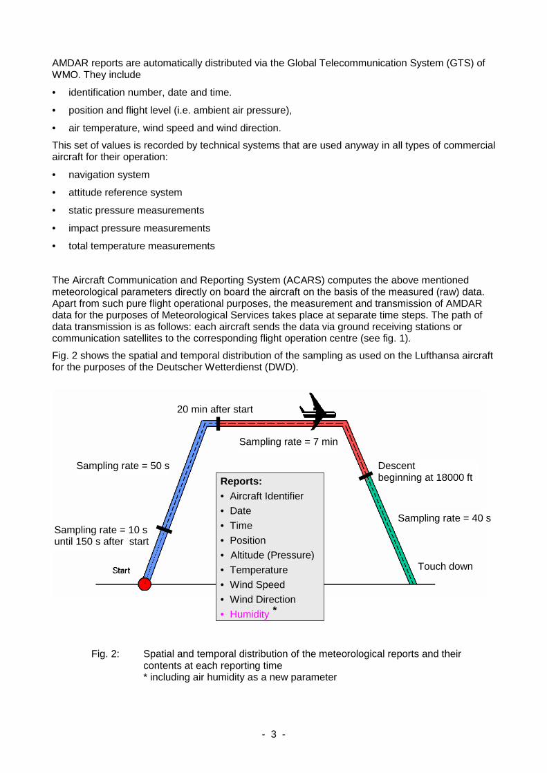
Table 1 presents an overview of the data yield and the AMDAR aircraft fleet. The DWD has a relatively high share of measurements per day, as compared with the number of aircraft. The reason for this is the specification given by the DWD defining a 1-hour time period for activated ascent and descent segments over central Europe, as opposed to the commonly required 3-hour time period. Fig. 3 shows the typical coverage of Europe with E-AMDAR measuring points.
AMDAR aircraft Measurements/day
DWD 289 21,000
EUMETNET-AMDAR 600 35,000
AMDAR worldwide 2,800 250,000
Table 1: AMDAR data yield and aircraft fleet (in 2007)
Fig. 3: 24-hour pattern of E-AMDAR measuring points for Europe

- 5 -
3 The potential for the extension of AMDAR’s benefi t
• Expansion and densification of the network on a global level - inclusion of more airlines - greater use of night-time starts and landings - international standards for aircraft producers to achieve AMDAR configuration ex works
• aircraft providing additional measurable variables - humidity - turbulence - icing - geometric height (GPS, GLONASS, GALILEO, etc.) - atmospheric chemistry parameters
• correction methods for systematic error components.
In order to reach the same type of data set as provided by the radiosondes in use around the world, highest priority must be given to including the parameter 'air humidity' into AMDAR measurements. This would make it possible to complement and also replace to a large extent the comparably expensive radiosoundings.
- 6 -
4 The measurement of humidity
So far the parameter 'humidity', which is essential for weather forecasting, has been measured to an extremely small extent within the worldwide AMDAR programme. Only the USA already has 25 aircraft equipped with humidity sensors that are designed for long-term routine operation.
4.1 Type of aircraft chosen for E-AMDAR
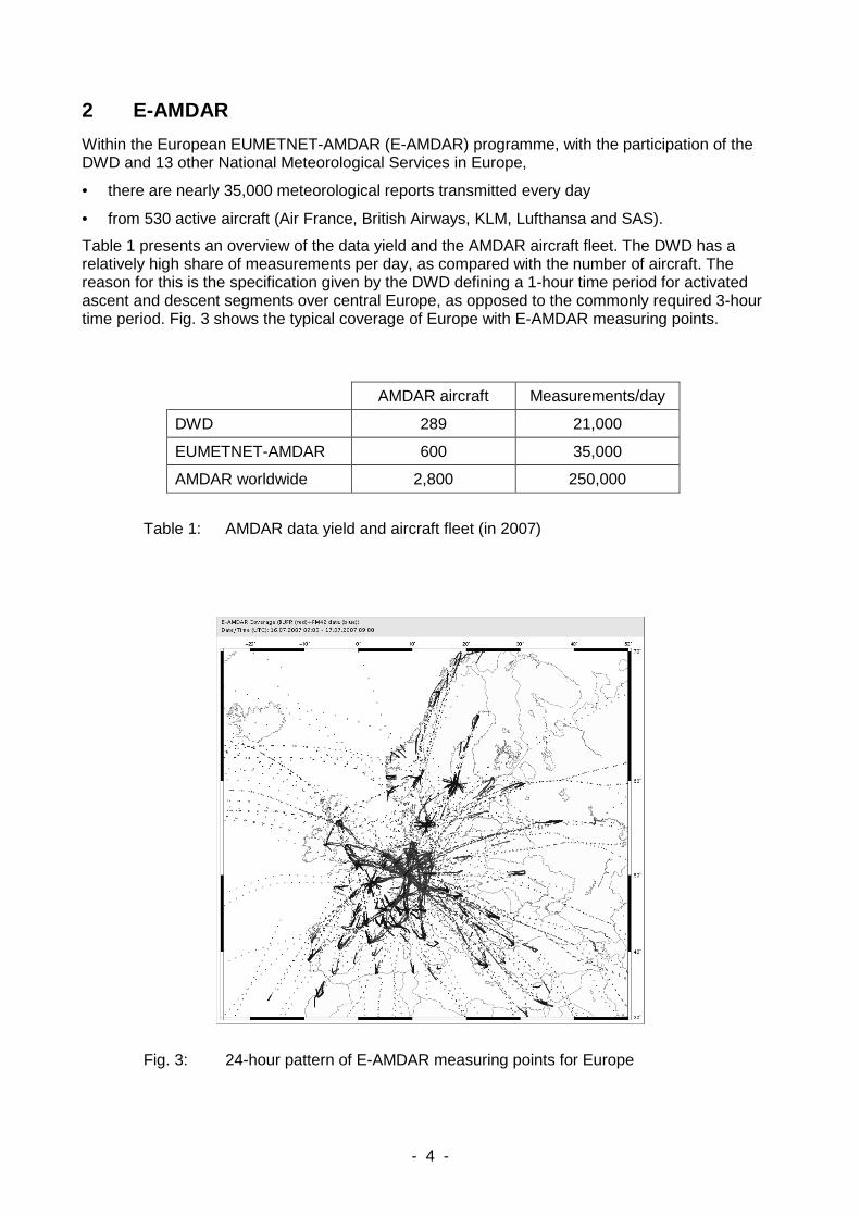
At the end of 2006 the first three Airbus A319 (see fig. 4) of Lufthansa, which for the purposes of the DWD is already participating in the E-AMDAR programme with 260 aircraft, were equipped additionally with the new sensor. So now the water vapour mixing ratio is added to the set of E-AMADAR parameters.
Fig. 4: Aircraft type chosen for the mounting of humidity sensors: Airbus A319 of the A320 family
The Airbus A320 family was chosen in order to achieve a data yield which is as far as possible of European origin and produce as many vertical profiles as possible per day from the starts and landings of short-range flights.
4.2 The sensing system
The sensor, SpectraSensors Inc. WVSS-II version 2006 (see fig. 5 and 6) is an infrared absorption spectroscope (water vapour line at 1.37 µm) on the basis a tuneable diode laser. The air to be measured is drawn through an 'air sampler', a device which is installed on the aircraft skin and, according to the initial conception of the construction, ensures the pressure neutral caption of the outside air flow, removing at the same time water and ice particles. The measurement takes place in the Sensor Electronics Box (SEB). This box contains a measurement cell with a length of 12 cm where the passing air is warmed up to around + 30°C . The mirrored measurement beam in the chamber travels 24 cm. The absorption values determined on the basis of the 2f method (Fleming & May, 2004), together with the pressure and temperature values measured in the box, are converted into water vapour mixing ratios. These values are then transmitted via a serial
- 7 -
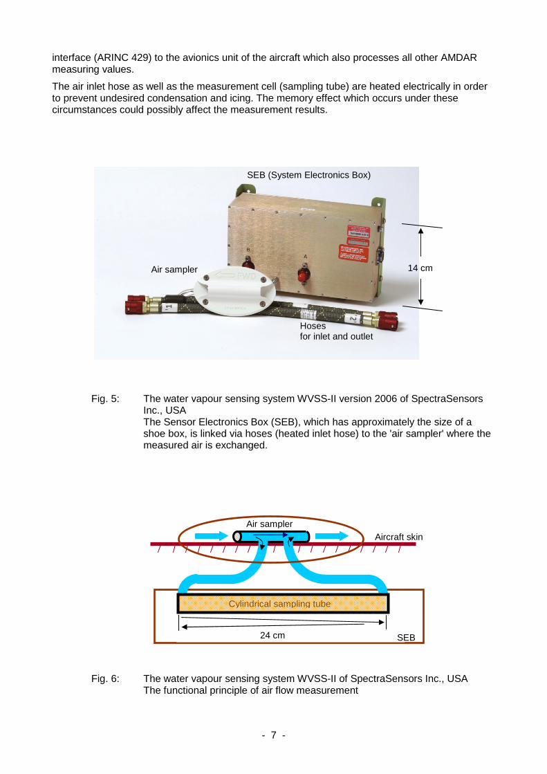
interface (ARINC 429) to the avionics unit of the aircraft which also processes all other AMDAR measuring values.
The air inlet hose as well as the measurement cell (sampling tube) are heated electrically in order to prevent undesired condensation and icing. The memory effect which occurs under these circumstances could possibly affect the measurement results.
Fig. 5: The water vapour sensing system WVSS-II version 2006 of SpectraSensors Inc., USA The Sensor Electronics Box (SEB), which has approximately the size of a shoe box, is linked via hoses (heated inlet hose) to the 'air sampler' where the measured air is exchanged.
Fig. 6: The water vapour sensing system WVSS-II of SpectraSensors Inc., USA The functional principle of air flow measurement
SEB (System Electronics Box)
Air sampler 14 cm
Hoses for inlet and outlet
Air sampler Aircraft skin
24 SE
Cylindrical sampling tube
24 cm SEB

- 8 -
4.3 Laboratory test results
The chosen sensor type was tested in the climate chambers of both the Research Centre Jülich (WVSS-II version 2005, see Smit & Sträter, 2006) and the Deutscher Wetterdienst Meteorological Observatory Lindenberg (WVSS-II version 2006).
Within the frostpoint/ dewpoint range - 60 and + 20 °C the relative deviation of the WVSS-II mixing ratio is observed within ± 10 % of the reference value (see Fig. 7).
Fig. 7: The test result of the WVSS-II version 2005 achieved in the climate chamber of the Research Centre Jülich: - relative deviation of the mixing ratio: graph adapted to the points - frost point temperature: graph plotted diagonally
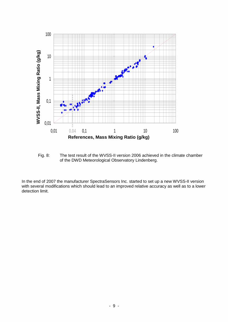
The result of the climate chamber test at the DWD Meteorological Observatory Lindenberg shows correspondingly similar results (see Fig. 8). Both laboratory tests show that the lower detection limit currently is at a water vapour mass mixing ratio of 0.04 g/kg (≈ 60 ppmv). In the mid-latitudes, under typical weather conditions, this corresponds to a usable area ranging from the ground to an altitude of maximally around 400 hPa in winter and 200 hPa in summer.
- 9 -
Fig. 8: The test result of the WVSS-II version 2006 achieved in the climate chamber of the DWD Meteorological Observatory Lindenberg.
In the end of 2007 the manufacturer SpectraSensors Inc. started to set up a new WVSS-II version with several modifications which should lead to an improved relative accuracy as well as to a lower detection limit.
0,01
0,1
1
10
100
0,01 0,1 1 10 100
Reference Mixing Ratio [ g/kg ]
Air
craf
t Sen
sor M
ixin
g R
atio
[ g/
kg
]
0.04
WV
SS
-II,
Mas
s M
ixin
g R
atio
(g/
kg)
References, Mass Mixing Ratio (g/kg)
- 10 -
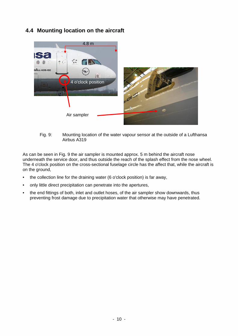
4.4 Mounting location on the aircraft
Fig. 9: Mounting location of the water vapour sensor at the outside of a Lufthansa Airbus A319
As can be seen in Fig. 9 the air sampler is mounted approx. 5 m behind the aircraft nose underneath the service door, and thus outside the reach of the splash effect from the nose wheel. The 4 o'clock position on the cross-sectional fuselage circle has the affect that, while the aircraft is on the ground,
• the collection line for the draining water (6 o'clock position) is far away,
• only little direct precipitation can penetrate into the apertures,
• the end fittings of both, inlet and outlet hoses, of the air sampler show downwards, thus preventing frost damage due to precipitation water that otherwise may have penetrated.
Air sampler
4.8 m
4 o’clock position

- 11 -
Fig. 10: Inside view of the mounting location of the water vapour sensor aboard the Lufthansa Airbus A319
On the inside, the Sensor Electronics Box (SEB) is fixed to the stiffening frame of the aircraft skin right above the air sampler (see fig. 10).
4.5 Operational measurement results
The humidity data are transmitted via the E-AMDAR network in exactly same way and without any restrictions as the parameters measured before.
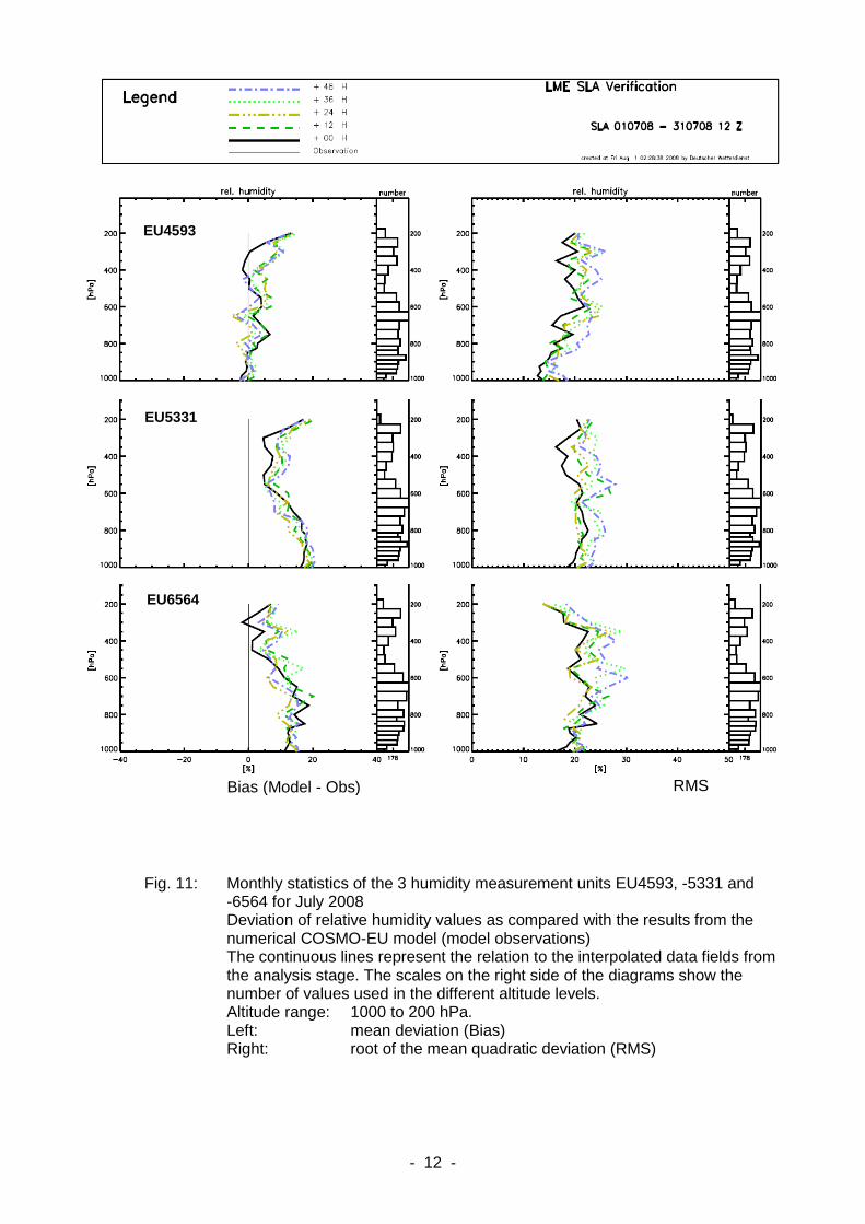
The measured data are currently subject to quality checks, consisting of a comparison with the short range forecasts from the numerical COSMO-EU model, i.e. the DWD's former Local Model for Europe, LME. Representatively for the other months an example statistics of July 2008 is shown in Fig. 11. The aircraft with the E-AMDAR identifier EU4593 shows no significant deviations from the reference. At present the other two measurement units, EU5331 and EU6564, provide relative humidity values that are around 10 to 15 % per cent too low. These deviations are still beyond the expected limits of ± 5 %. This observation roughly corresponds to the results of the climate chamber tests.
The decimal encoding used for the data link between aircraft and ground currently still implies restrictions on the relative accuracy of the values. Here the aim is to adapt the globally accepted format to allow for a resolution which is far more appropriate for this measurement concept. The on-board software still has to be changed accordingly. For all sensors, as a sum of both the deviations and the encoding, the root mean square error amounts to around 20 % of relative humidity.
- 12 -
Fig. 11: Monthly statistics of the 3 humidity measurement units EU4593, -5331 and -6564 for July 2008 Deviation of relative humidity values as compared with the results from the numerical COSMO-EU model (model observations) The continuous lines represent the relation to the interpolated data fields from the analysis stage. The scales on the right side of the diagrams show the number of values used in the different altitude levels. Altitude range: 1000 to 200 hPa. Left: mean deviation (Bias) Right: root of the mean quadratic deviation (RMS)
EU4593
EU5331
EU6564
Bias (Model - Obs) RMS

- 13 -
4.6 Ideas for an additional improvement of the syst em
For the WVSS-II version 2008 a lot of reengineering in the electronic parts and in the tightness of the Laser unit has been done. EUMETNET is preparing to equip a greater number of aircraft with humidity sensors of the next generation. On the initiative of WMO (i.e. the WMO AMDAR Panel), a campaign was started to develop a standard configuration for all newly produced aircraft, which makes the operation of AMDAR possible from the outset and also ensures that the mechanical and electrical interfaces for the installation of humidity sensors are included.
The required development stages should also include changes of both the physical principle of the processing of the air to be measured and the laser measurement technique.
The air inlet should be outside the fuselage bounda ry layer:
The current inlet unit takes the air to be measured from the air stream which is in contact with the aircraft skin. Under cold conditions the memory effect can considerably distort the prevailing water vapour pressure. This process, which is difficult to calculate, can be completely excluded if the air inlet into the hose system is located above the boundary layer. The result would be
(+) the guaranteed exclusion of the memory effect and contamination,
(-) the necessity of de-icing for flight safety reasons,
The air inlet could be the housing of a total air temperature sensor (TAT) flush mounted with an extent of around 12 cm and an exchangeable measuring unit, for example the Rosemount sensor types 102 BW or 102 BX. By this housing a separation of the water and ice particles is performed in the same amount as it is done by that of the Air Sampler. The temperature measuring element inside the TAT housing could be replaced by an inlet/outlet unit to be connected via hoses with the SEB. The mounting location would have to be chosen according to the same rules applying to any other TAT unit.
Instead of its local ambient pressure, the air to b e measured should have the impact pressure.
This could, for example, be achieved with a TAT housing. The results at Mach 0.8 would be:
● an adiabatic temperature increase by up to + 30 K (+ 6 K at Mach 0.3)
(+) no precautions against condensation and icing required (heating of hose and sampling tube no longer necessary)
(-) maximum internal air temperature of + 60 °C at - 1000 hPa (low flight level) - ambient temperature at + 45 °C
● pressure increase by up to 250 hPa (70 hPa at Mach 0.3 and altitude 1000 hPa)
(+) increased sensitivity of the measurement method in the upper part of the troposphere,
(+) less strain on the system resulting from the pressure difference between the cabin and the air sampling system,
(-) slightly increased dew point, which makes it necessary to limit the thermal conduction of the air flow into the internal walls on its way to the measuring unit (a problem which is technically solvable).
Multiple measuring chambers: The installation of two measuring chambers, mounted either parallel or in series and with different absorption lengths, would considerably enlarge the present range of use (0.04 g/kg to around 20 g/kg). The present measurement range of 3 orders of magnitude could be increased to the size of 5, which better corresponds to the real troposphere (0.002 to 20 g/kg).
- 14 -
Literature Fleming, R., May, R.: The 2nd Generation Water Vapor Sensing System and Benefits of Its Use on
Commercial Aircraft for Air Carriers and Society, SpectraSensors (2004), 21 pp., http://www.eol.ucar.edu/projects/wvss/spectrasensors.pdf
Smit, H.G.J., Sträter, W.: Performance of a New Airborne Water Vapor Sensor (WVSS-II): Results from Tests in the FZJ Environmental Simulation Facility, Contribution to IAGOS - Annual Report Year #1 (May 2005 - April, 2006), Research Centre Jülich
WMO No. 8, WMO Guide to Meteorological Instruments and Methods of Observation, Secretariat of the WMO (2006), 569 pp., http://www.wmo.ch/pages/prog/www/IMOP/publications/CIMO-Guide/WMO-No_8.pdf
WMO No. 958 (2003), Aircraft Meteorological Data Relay (AMDAR) Reference Manual, Secretariat of the WMO (2003), 80 pp., http://amdar.wmo.int/Publications/AMDAR_Reference_Manual_2003.pdf