Humanoid Balancing Behavior Featured by Underactuated Foot ...
23
This is a repository copy of Humanoid Balancing Behavior Featured by Underactuated Foot Motion. White Rose Research Online URL for this paper: http://eprints.whiterose.ac.uk/144477/ Version: Accepted Version Article: Li, Z, Zhou, C orcid.org/0000-0002-6677-0855, Zhu, Q et al. (1 more author) (2017) Humanoid Balancing Behavior Featured by Underactuated Foot Motion. IEEE Transactions on Robotics, 33 (2). pp. 298-312. ISSN 1552-3098 https://doi.org/10.1109/TRO.2016.2629489 © 2017 IEEE. Personal use of this material is permitted. Permission from IEEE must be obtained for all other uses, in any current or future media, including reprinting/republishing this material for advertising or promotional purposes, creating new collective works, for resale or redistribution to servers or lists, or reuse of any copyrighted component of this work in other works. [email protected] https://eprints.whiterose.ac.uk/ Reuse Items deposited in White Rose Research Online are protected by copyright, with all rights reserved unless indicated otherwise. They may be downloaded and/or printed for private study, or other acts as permitted by national copyright laws. The publisher or other rights holders may allow further reproduction and re-use of the full text version. This is indicated by the licence information on the White Rose Research Online record for the item. Takedown If you consider content in White Rose Research Online to be in breach of UK law, please notify us by emailing [email protected] including the URL of the record and the reason for the withdrawal request.
Transcript of Humanoid Balancing Behavior Featured by Underactuated Foot ...
This is a repository copy of Humanoid Balancing Behavior Featured by Underactuated Foot Motion.
White Rose Research Online URL for this paper:http://eprints.whiterose.ac.uk/144477/
Version: Accepted Version
Article:
Li, Z, Zhou, C orcid.org/0000-0002-6677-0855, Zhu, Q et al. (1 more author) (2017) Humanoid Balancing Behavior Featured by Underactuated Foot Motion. IEEE Transactions on Robotics, 33 (2). pp. 298-312. ISSN 1552-3098
https://doi.org/10.1109/TRO.2016.2629489
© 2017 IEEE. Personal use of this material is permitted. Permission from IEEE must be obtained for all other uses, in any current or future media, including reprinting/republishing this material for advertising or promotional purposes, creating new collective works, for resale or redistribution to servers or lists, or reuse of any copyrighted component of this work in other works.
[email protected]://eprints.whiterose.ac.uk/
Reuse
Items deposited in White Rose Research Online are protected by copyright, with all rights reserved unless indicated otherwise. They may be downloaded and/or printed for private study, or other acts as permitted by national copyright laws. The publisher or other rights holders may allow further reproduction and re-use of the full text version. This is indicated by the licence information on the White Rose Research Online record for the item.
Takedown
If you consider content in White Rose Research Online to be in breach of UK law, please notify us by emailing [email protected] including the URL of the record and the reason for the withdrawal request.
THIS IS AUTHOR DRAFT, PLEASE FIND OFFICIAL VERSION IN IEEE TRANSACTION ON ROBOTICS, VOLUME 33 , ISSUE 2, 2017 1
Humanoid Balancing Behavior Featured by
Underactuated Foot MotionZhibin Li, Chengxu Zhou, Qiuguo Zhu, Rong Xiong †
Abstract
A novel control synthesis is proposed for humanoids to demonstrate unique foot tilting behaviors comparable to humans inbalance recovery. Our study of model based behaviors explains the underlying mechanism and the significance of foot tilting well.Our main algorithms are composed of impedance control at the center of mass, virtual stoppers that prevents over-tilting of thefeet, and postural control for the torso. The proof of concept focuses on the sagittal scenario and the proposed control is effectiveto produce human-like balancing behaviors characterized by active foot tilting. The successful replication of this behavior on a realhumanoid proves the feasibility of deliberately controlled underactuation. The experimental validation was rigorously performed,and the data from the sub-modules and the entire control were presented and analyzed.
Index Terms
Balance Control, Humanoid Robot, Under-actuation, Foot Rotation.
I. INTRODUCTION
The biomechanical study of human locomotion reveals the phenomenon of underactuation during standing balance and
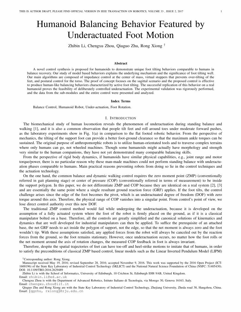
walking [1], and it is also a common observation that people tilt feet and roll around toes under moderate forward pushes,
as the laboratory experiments show in Fig. 1(a) in comparison to the flat footed robotic behavior. From the perspective of
mechanics, the tilting of the support foot can provide a better foot-ground clearance so that the maximum ankle torques can be
sustained. The original purpose of anthropomorphic robots is to utilize human-orientated tools and to traverse complex terrains
where only humans can go, not wheeled machines. Though some humanoids might actually have morphology and strength
very similar to the human companions, they have not yet demonstrated many comparable balancing skills.
From the perspective of rigid body dynamics, if humanoids have similar physical capabilities, e.g., joint range and motor
torque/power, there is no particular reason why these man-made machines could not perform standing balance with underactu-
ation phases comparable to humans. Main practical reasons preventing robots from doing so lie in the control techniques and
the actuation technology.
On the one hand, the common balance and dynamic walking control requires the zero moment point (ZMP) (conventionally
referred in gait planning stage) or center of pressure (COP) (conventionally referred in terms of measurement) to be inside
the support polygon. In this paper, we do not differentiate ZMP and COP because they are identical on a real system [2], [3]
and are essentially the same point where a single resultant ground reaction force (GRF) applies. If the foot tilts, the control
challenge arises since the edge of the foot becomes the pivot, which is an underactuated degree of freedom (DOF) with zero
torque around this axis. Therefore, the physical range of COP vanishes into a singular point. From control’s point of view, we
lose direct control authority over this new DOF.
The traditional ZMP control method would fail while undergoing the underactuation, because it is developed on the
assumption of a fully actuated system where the foot of the robot is firmly placed on the ground, as if it is a classical
manipulator bolted on a base. Therefore, all the controls are greatly simplified and the canonical solutions of kinematics and
dynamics that are well developed for industrial manipulators can then be applied. To suffice the prerequisite of an attached
base, the net GRF needs to act inside the polygon of support, not the edge, so that the net moment is always zero and the foot
wouldn’t tip. With these assumptions satisfied, any applied forces from the robot will always be canceled out by the reaction
forces from the ground, so the foot remains stationary. However, once underactuation occurs, no matter how the foot rolls or
the net moment around the axis of rotation changes, the measured COP feedback in foot is always invariant.
Therefore, despite the spatial trajectories of feet can have toe-off and heel-strike motions to imitate that of humans, in order
to satisfy the preconditions of classical ZMP based control, linear models such as the Linear Inverted Pendulum Model (LIPM)
†Corresponding author: Rong Xiong.Manuscript received May 19, 2016; revised September 28, 2016; accepted November 9, 2016. This work was supported by the 2016 Open Project (ICT-
1600196) of the State Key Laboratory of Industrial Control Technology (SKLICT) and the National Natural Science Foundation of China (NSFC: 51405430).DOI: 10.1109/TRO.2016.2629489
Zhibin Li is with the School of Informatics, University of Edinburgh, 10 Crichton St, Edinburgh EH8 9AB, United Kingdom.Email: [email protected]
Chengxu Zhou is with the Department of Advanced Robotics, Istituto Italiano di Tecnologia, via Morego 30, Genova 16163, Italy.Email: [email protected]
Qiuguo Zhu and Rong Xiong are with the State Key Laboratory of Industrial Control Technology, Zhejiang University, Zheda road 38, Hangzhou, China.Email: {qgzhu, rxiong}@zju.edu.cn
THIS IS AUTHOR DRAFT, PLEASE FIND OFFICIAL VERSION IN IEEE TRANSACTION ON ROBOTICS, VOLUME 33 , ISSUE 2, 2017 2
Fig. 1: The underactuation behaviors in human and humanoid push recoveries: (a) foot tilting observed from a person’s response;
(b) a humanoid with our proposed control can perform human-comparable foot tilting; (c) the conventional balance control
with flat-footed behavior.
[4] or the Cart-table Model [5] are typically used to generate center of mass (COM) motions, so the resulted ZMP is preferably
limited inside the support polygon. Especially because the foot may start to roll due to the deformation of materials underneath
the foot, large safety margins are planned as possible at every time instant [6] [7] [8].
In contrast, during heel-strike and toe-off phases in human locomotion and passive dynamic walkers [9] [10], the actual
GRF acts inside a narrow support area or nearly a point in the rolling foot. Though ZMP/COP is still the point where the
resultant GRF applies, the geometric distance between the ZMP/COP and the edge of the polygon of support is no longer
reasonable to imply the level of balance that whether or not a person/robot is going to fall. Because of this, other physical
quantities were proposed from aspects of orbital energy [11] and mechanical energy [12] [13]. Particularly, the Capture Point
is a simple and straightforward measure of balance [11]. Based on that, some gait control methods developed in [8] [14] have
shown the feasibility of using Capture Point to generate dynamic gaits in real bipedal systems other than the ZMP approach.
Hence, in this study, we present the experimental data of Capture Point together with other measurements to show that the
robot did not fall as long as the Capture Point is bounded by the convex of a reachable support region.
On the other hand, apart from the stability indicators that limit the exploration of underactuation phases, another major
limitation comes from the actuation technology. So far, the majority of actuators are position controlled. Because locomotion is
a physical interaction that involves contact forces between the robot and the environment, a purely position controlled system
is vulnerable to any unexpected discrepancies. The highly stiff position control can cause damages during any undesired
collision, whereas the low stiffness case trades off tracking accuracy in the task space. Therefore, to achieve good locomotion
and balancing performance, torque control is very much favored because it permits precise position tracking during collision-
free motion and, meanwhile, renders desired contact forces to remain compliant during physical interactions which in turn
preserves contacts very well [15] [16].
A. Related Work and Motivation
Hofmann et al. [17] carried out simulation study on the utilization of angular momentum created by non-contact limbs for
dynamic balance recovery, and Atkeson et al. [18] demonstrated multiple behaviors by using one single optimization policy
for standing balance control. However, in both cases, the applied ankle torque was restricted to prevent tipping of the stance
foot. Among the powered bipeds that demonstrated the toe-off and heel-strike [19], [20], [21], their underactuation phases
emerged from the assistive control of passive dynamic gaits. Though the Petman prototype from Boston Dynamics has also
shown human-like walking with heel-toe transitions, no publication reveals the control details.
Our previous study in [22] demonstrated that the robot could have a short portion of underactuation phase without falling.
It shall be distinguished that our proposed scheme in this paper is a proactive approach that deliberately makes use of
underactuation to enhance balance recovery, while the previous work in [22] merely targeted at suspending unstable oscillation
during foot tilting so the underactuation occurred passively due to larger pushes. Hence, that underactuation behavior in [22]
was not an actively controlled behavior.
The standing balance control can be classified into two categories by the actuation technologies. One is the position based
control that typically utilizes a simplified low dimensional model, calculates the desired Cartesian references by satisfying
contact force constraint such as ZMP, and obtains the position reference in joint space via inverse kinematics [23], [24]. The
other is the torque based control that has the feedback loop of the targeted objectives at the Cartesian space and uses the joint
torque capability to directly apply the desired wrench to deliver the control actions [25], [26], [27]. Our proposed strategy
belongs to the latter category.
Given the torque controlled ankles, the control then acquires the ability to actively regulate the COP at the edge of the
support feet. Therefore, the balance recovery performance can be maximized by exerting the largest ankle torque as possible.
THIS IS AUTHOR DRAFT, PLEASE FIND OFFICIAL VERSION IN IEEE TRANSACTION ON ROBOTICS, VOLUME 33 , ISSUE 2, 2017 3
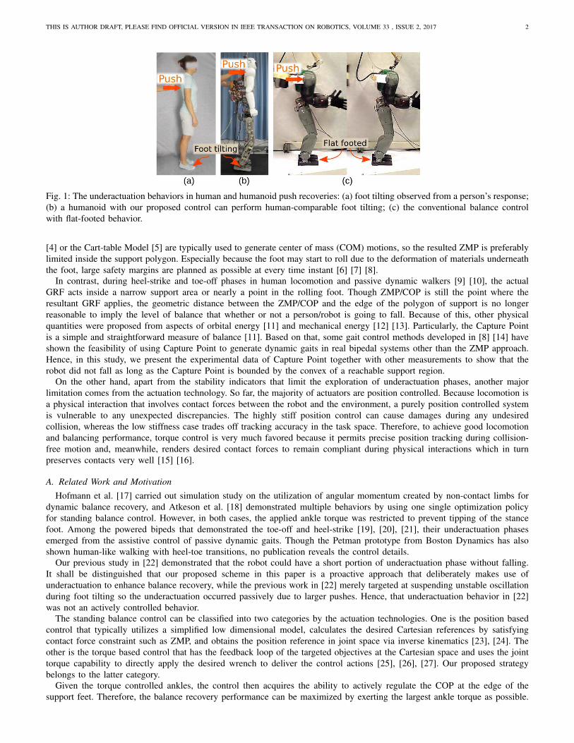
(a) (c)
τankle
ωd
Segmental
COM
Overall COM
(b)
Φb
xcom
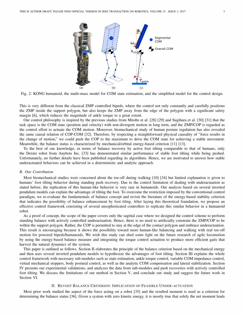
Fig. 2: KONG humanoid, the multi-mass model for COM state estimation, and the simplified model for the control design.
This is very different from the classical ZMP controlled bipeds, where the control not only constantly and carefully positions
the ZMP inside the support polygon, but also keeps the ZMP away from the edge of the polygon with a significant safety
margin [6], which reduces the magnitude of ankle torque to a great extent.
Our control philosophy is inspired by the previous studies from Mitobe et al. [28] [29] and Sugihara et al. [30] [31] that the
task space is the COM state (position and velocity) with non-divergent motion in long term, and the ZMP/COP is regarded as
the control effort to actuate the COM motion. Moreover, biomechanical study of human posture regulation has also revealed
the same causal relation of COP-COM [32]. Therefore, by respecting a straightforward physical causality of “force results in
the change of motion,” we could push the COP to the maximum to drive the COM state for achieving a stable movement.
Meanwhile, the balance status is characterized by mechanical/orbital energy-based criterion [11] [13].
To the best of our knowledge, in terms of balance recovery by active foot tilting comparable to that of humans, only
the Dexter robot from Anybots Inc. [33] has demonstrated similar performance of stable foot tilting while being pushed.
Unfortunately, no further details have been published regarding its algorithms. Hence, we are motivated to answer how stable
underactuated behaviors can be achieved in a deterministic and analytic approach.
B. Our Contribution
Most biomechanical studies were concerned about the toe-off during walking [10] [34] but limited explanation is given to
humans’ foot tilting behavior during standing push recovery. Due to the control limitation of dealing with underactuation as
stated before, the replication of this human-like behavior is very rare in humanoids. Our analysis based on several inverted
pendulum models can explain the advantage of tilting the foot. To overcome the restriction imposed by the conventional control
paradigm, we re-evaluate the fundamentals of balance concept and revisit the literature of the energy-based stability criterion
that indicates the possibility of balance enhancement by foot tiling. After laying this theoretical foundation, we propose an
effective control framework consisting of several unsophisticated controllers to replicate this similar behavior in a humanoid
robot.
As a proof of concept, the scope of the paper covers only the sagittal case where we designed the control scheme to perform
standing balance with actively controlled underactuation. Hence, there is no need to artificially constrain the ZMP/COP to be
within the support polygon. Rather, the COP is permitted to stay at the edge of the contact polygon and embrace underactuation.
This result is encouraging because it shows the possibility toward more human-like balancing and walking with real toe-off
motion for powered bipeds/humanoids. We wish this study can shed some light on the future research of agile locomotion
by using the energy-based balance measure and integrating the torque control actuation to produce more efficient gaits that
harvest the natural dynamics of the system.
This paper is outlined as follows. Section II elaborates the principle of the balance criterion based on the mechanical energy
and then uses several inverted pendulum models to hypothesize the advantages of foot tilting. Section III explains the whole
control framework with necessary sub-modules such as state estimation, ankle torque control, variable COM impedance control,
virtual mechanical stoppers, body postural control, as well as the analytic COM compensation and lateral stabilization. Section
IV presents our experimental validations, and analyzes the data from sub-modules and push recoveries with actively controlled
foot tilting. We discuss the limitations of our method in Section V, and conclude our study and suggest the future work in
Section VI.
II. REVISIT BALANCE CRITERION: IMPLICATION OF FEASIBLE UNDER-ACTUATION
Most prior work studied the aspect of the force acting on a robot [35] and the resulted moment is used as a criterion for
determining the balance status [36]. Given a system with zero kinetic energy, it is mostly true that solely the net moment leads
THIS IS AUTHOR DRAFT, PLEASE FIND OFFICIAL VERSION IN IEEE TRANSACTION ON ROBOTICS, VOLUME 33 , ISSUE 2, 2017 4
TABLE I: Parameters of Kong Robot
Segment Mass [kg] Length(vertical) [m] Width(lateral) [m]
Torso 17.67 0.42 0.44Pelvis 9.3 0.236 0.206Thigh 4.90 0.314 0.14Shin 2.81 0.30 0.12Foot 3.19 0.107 0.07
(a) (c)(b)
r0
dfdr
F
r0 r0
df
θa
θ0
rf
rf rf'
(d)
df
v v
df
ω
pivot
θ0
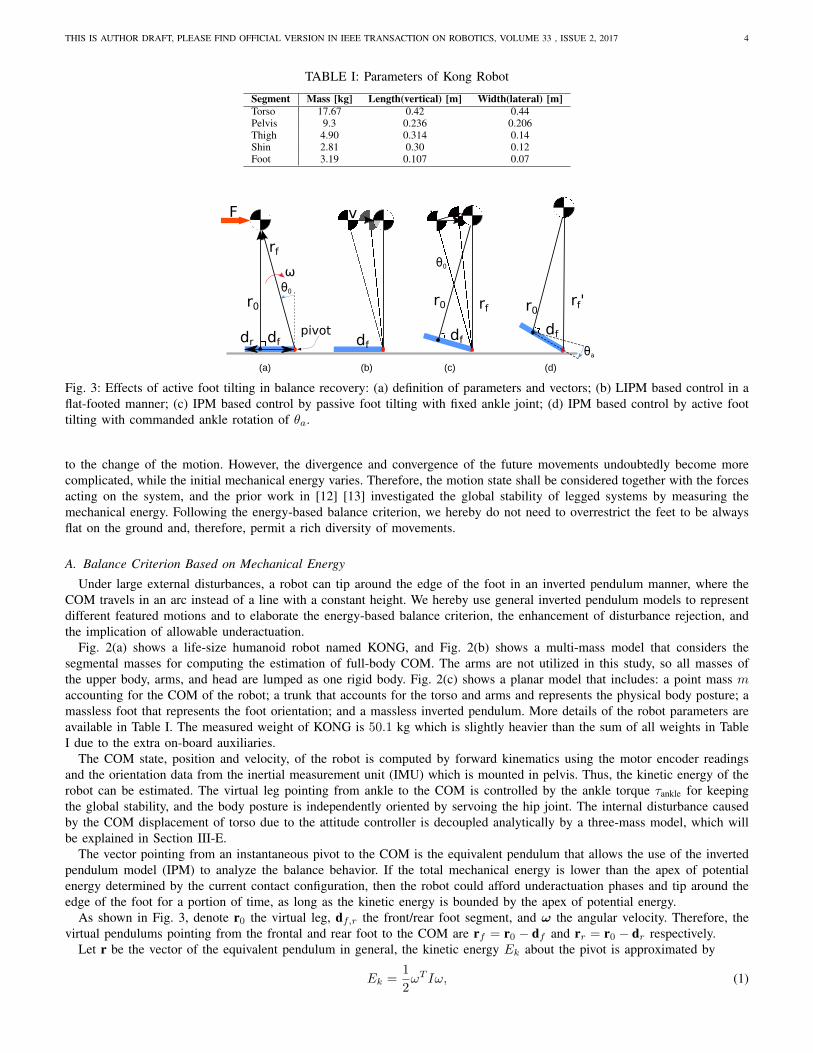
Fig. 3: Effects of active foot tilting in balance recovery: (a) definition of parameters and vectors; (b) LIPM based control in a
flat-footed manner; (c) IPM based control by passive foot tilting with fixed ankle joint; (d) IPM based control by active foot
tilting with commanded ankle rotation of θa.
to the change of the motion. However, the divergence and convergence of the future movements undoubtedly become more
complicated, while the initial mechanical energy varies. Therefore, the motion state shall be considered together with the forces
acting on the system, and the prior work in [12] [13] investigated the global stability of legged systems by measuring the
mechanical energy. Following the energy-based balance criterion, we hereby do not need to overrestrict the feet to be always
flat on the ground and, therefore, permit a rich diversity of movements.
A. Balance Criterion Based on Mechanical Energy
Under large external disturbances, a robot can tip around the edge of the foot in an inverted pendulum manner, where the
COM travels in an arc instead of a line with a constant height. We hereby use general inverted pendulum models to represent
different featured motions and to elaborate the energy-based balance criterion, the enhancement of disturbance rejection, and
the implication of allowable underactuation.
Fig. 2(a) shows a life-size humanoid robot named KONG, and Fig. 2(b) shows a multi-mass model that considers the
segmental masses for computing the estimation of full-body COM. The arms are not utilized in this study, so all masses of
the upper body, arms, and head are lumped as one rigid body. Fig. 2(c) shows a planar model that includes: a point mass maccounting for the COM of the robot; a trunk that accounts for the torso and arms and represents the physical body posture; a
massless foot that represents the foot orientation; and a massless inverted pendulum. More details of the robot parameters are
available in Table I. The measured weight of KONG is 50.1 kg which is slightly heavier than the sum of all weights in Table
I due to the extra on-board auxiliaries.
The COM state, position and velocity, of the robot is computed by forward kinematics using the motor encoder readings
and the orientation data from the inertial measurement unit (IMU) which is mounted in pelvis. Thus, the kinetic energy of the
robot can be estimated. The virtual leg pointing from ankle to the COM is controlled by the ankle torque τankle for keeping
the global stability, and the body posture is independently oriented by servoing the hip joint. The internal disturbance caused
by the COM displacement of torso due to the attitude controller is decoupled analytically by a three-mass model, which will
be explained in Section III-E.
The vector pointing from an instantaneous pivot to the COM is the equivalent pendulum that allows the use of the inverted
pendulum model (IPM) to analyze the balance behavior. If the total mechanical energy is lower than the apex of potential
energy determined by the current contact configuration, then the robot could afford underactuation phases and tip around the
edge of the foot for a portion of time, as long as the kinetic energy is bounded by the apex of potential energy.
As shown in Fig. 3, denote r0 the virtual leg, df,r the front/rear foot segment, and ω the angular velocity. Therefore, the
virtual pendulums pointing from the frontal and rear foot to the COM are rf = r0 − df and rr = r0 − dr respectively.
Let r be the vector of the equivalent pendulum in general, the kinetic energy Ek about the pivot is approximated by
Ek =1
2ωT Iω, (1)
THIS IS AUTHOR DRAFT, PLEASE FIND OFFICIAL VERSION IN IEEE TRANSACTION ON ROBOTICS, VOLUME 33 , ISSUE 2, 2017 5
0.2 0.0 0.2 0.4x [m]
0.0
0.2
0.4
0.6
0.8z
[m]
(a)
0.2 0.0 0.2 0.4x [m]
0.0
0.2
0.4
0.6
0.8
z [m
](b)
0.2 0.0 0.2 0.4x [m]
0.0
0.2
0.4
0.6
0.8
z [m
]
(c)
0.2 0.0 0.2 0.4x [m]
0.0
0.2
0.4
0.6
0.8
z [m
]
(d)
0.0 0.3 0.6 0.9 1.2 1.5Time [s]
0.00
0.02
0.04
0.06
0.08
0.10
0.12
Posi
tion
[m]
(e)
xCOM
xCP
xCOP
0.0 0.3 0.6 0.9 1.2 1.5Time [s]
0.00
0.02
0.04
0.06
0.08
0.10
0.12
Posi
tion
[m]
(f)
xCOM
xCP
xCOP
0.0 0.3 0.6 0.9 1.2 1.5Time [s]
0.00
0.02
0.04
0.06
0.08
0.10
0.12
Posi
tion
[m]
velocity redirected
(g)
xCOM
xCP
xCOP
0.0 0.3 0.6 0.9 1.2 1.5Time [s]
0.00
0.02
0.04
0.06
0.08
0.10
0.12
Posi
tion
[m]
velocity redirected
(h)
xCOM
xCP
xCOP
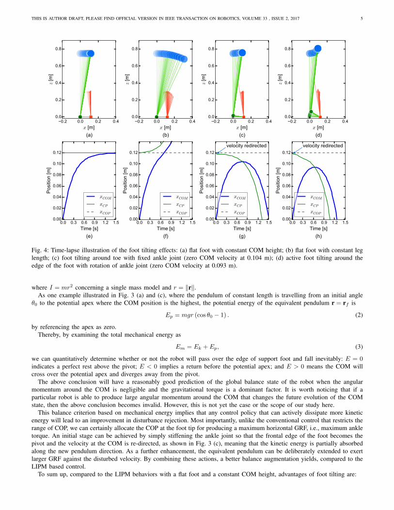
Fig. 4: Time-lapse illustration of the foot tilting effects: (a) flat foot with constant COM height; (b) flat foot with constant leg
length; (c) foot tilting around toe with fixed ankle joint (zero COM velocity at 0.104 m); (d) active foot tilting around the
edge of the foot with rotation of ankle joint (zero COM velocity at 0.093 m).
where I = mr2 concerning a single mass model and r = ‖r‖.
As one example illustrated in Fig. 3 (a) and (c), where the pendulum of constant length is travelling from an initial angle
θ0 to the potential apex where the COM position is the highest, the potential energy of the equivalent pendulum r = rf is
Ep = mgr (cos θ0 − 1) . (2)
by referencing the apex as zero.
Thereby, by examining the total mechanical energy as
Em = Ek + Ep, (3)
we can quantitatively determine whether or not the robot will pass over the edge of support foot and fall inevitably: E = 0indicates a perfect rest above the pivot; E < 0 implies a return before the potential apex; and E > 0 means the COM will
cross over the potential apex and diverges away from the pivot.
The above conclusion will have a reasonably good prediction of the global balance state of the robot when the angular
momentum around the COM is negligible and the gravitational torque is a dominant factor. It is worth noticing that if a
particular robot is able to produce large angular momentum around the COM that changes the future evolution of the COM
state, then the above conclusion becomes invalid. However, this is not yet the case or the scope of our study here.
This balance criterion based on mechanical energy implies that any control policy that can actively dissipate more kinetic
energy will lead to an improvement in disturbance rejection. Most importantly, unlike the conventional control that restricts the
range of COP, we can certainly allocate the COP at the foot tip for producing a maximum horizontal GRF, i.e., maximum ankle
torque. An initial stage can be achieved by simply stiffening the ankle joint so that the frontal edge of the foot becomes the
pivot and the velocity at the COM is re-directed, as shown in Fig. 3 (c), meaning that the kinetic energy is partially absorbed
along the new pendulum direction. As a further enhancement, the equivalent pendulum can be deliberately extended to exert
larger GRF against the disturbed velocity. By combining these actions, a better balance augmentation yields, compared to the
LIPM based control.
To sum up, compared to the LIPM behaviors with a flat foot and a constant COM height, advantages of foot tilting are:
THIS IS AUTHOR DRAFT, PLEASE FIND OFFICIAL VERSION IN IEEE TRANSACTION ON ROBOTICS, VOLUME 33 , ISSUE 2, 2017 6
Ankle rotation angle [deg]
05
1015
2025
Foot length [m
]
0.08
0.13
0.18
Sto
ppin
g d
ista
nce [
m]
0.00
0.01
0.02
0.03
0.04
0.05
0.06
0.07
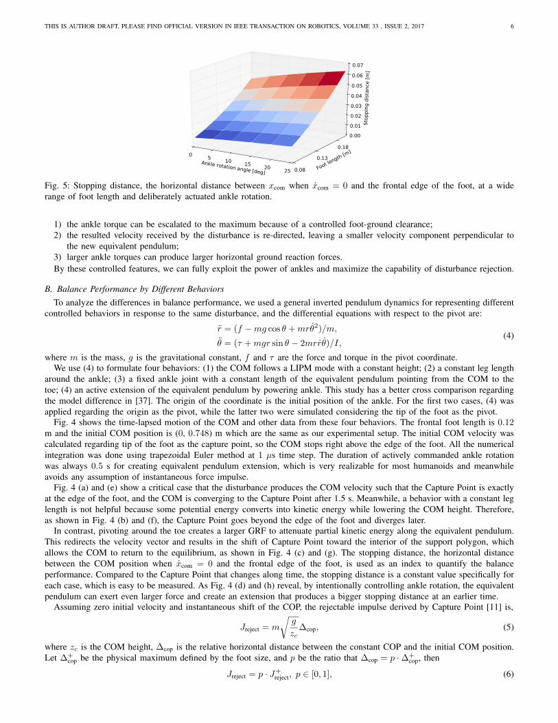
Fig. 5: Stopping distance, the horizontal distance between xcom when xcom = 0 and the frontal edge of the foot, at a wide
range of foot length and deliberately actuated ankle rotation.
1) the ankle torque can be escalated to the maximum because of a controlled foot-ground clearance;
2) the resulted velocity received by the disturbance is re-directed, leaving a smaller velocity component perpendicular to
the new equivalent pendulum;
3) larger ankle torques can produce larger horizontal ground reaction forces.
By these controlled features, we can fully exploit the power of ankles and maximize the capability of disturbance rejection.
B. Balance Performance by Different Behaviors
To analyze the differences in balance performance, we used a general inverted pendulum dynamics for representing different
controlled behaviors in response to the same disturbance, and the differential equations with respect to the pivot are:
r = (f −mg cos θ +mrθ2)/m,
θ = (τ +mgr sin θ − 2mrrθ)/I,(4)
where m is the mass, g is the gravitational constant, f and τ are the force and torque in the pivot coordinate.
We use (4) to formulate four behaviors: (1) the COM follows a LIPM mode with a constant height; (2) a constant leg length
around the ankle; (3) a fixed ankle joint with a constant length of the equivalent pendulum pointing from the COM to the
toe; (4) an active extension of the equivalent pendulum by powering ankle. This study has a better cross comparison regarding
the model difference in [37]. The origin of the coordinate is the initial position of the ankle. For the first two cases, (4) was
applied regarding the origin as the pivot, while the latter two were simulated considering the tip of the foot as the pivot.
Fig. 4 shows the time-lapsed motion of the COM and other data from these four behaviors. The frontal foot length is 0.12m and the initial COM position is (0, 0.748) m which are the same as our experimental setup. The initial COM velocity was
calculated regarding tip of the foot as the capture point, so the COM stops right above the edge of the foot. All the numerical
integration was done using trapezoidal Euler method at 1 µs time step. The duration of actively commanded ankle rotation
was always 0.5 s for creating equivalent pendulum extension, which is very realizable for most humanoids and meanwhile
avoids any assumption of instantaneous force impulse.
Fig. 4 (a) and (e) show a critical case that the disturbance produces the COM velocity such that the Capture Point is exactly
at the edge of the foot, and the COM is converging to the Capture Point after 1.5 s. Meanwhile, a behavior with a constant leg
length is not helpful because some potential energy converts into kinetic energy while lowering the COM height. Therefore,
as shown in Fig. 4 (b) and (f), the Capture Point goes beyond the edge of the foot and diverges later.
In contrast, pivoting around the toe creates a larger GRF to attenuate partial kinetic energy along the equivalent pendulum.
This redirects the velocity vector and results in the shift of Capture Point toward the interior of the support polygon, which
allows the COM to return to the equilibrium, as shown in Fig. 4 (c) and (g). The stopping distance, the horizontal distance
between the COM position when xcom = 0 and the frontal edge of the foot, is used as an index to quantify the balance
performance. Compared to the Capture Point that changes along time, the stopping distance is a constant value specifically for
each case, which is easy to be measured. As Fig. 4 (d) and (h) reveal, by intentionally controlling ankle rotation, the equivalent
pendulum can exert even larger force and create an extension that produces a bigger stopping distance at an earlier time.
Assuming zero initial velocity and instantaneous shift of the COP, the rejectable impulse derived by Capture Point [11] is,
Jreject = m
√
g
zc∆cop, (5)
where zc is the COM height, ∆cop is the relative horizontal distance between the constant COP and the initial COM position.
Let ∆+cop be the physical maximum defined by the foot size, and p be the ratio that ∆cop = p ·∆+
cop, then
Jreject = p · J+
reject, p ∈ [0, 1], (6)
THIS IS AUTHOR DRAFT, PLEASE FIND OFFICIAL VERSION IN IEEE TRANSACTION ON ROBOTICS, VOLUME 33 , ISSUE 2, 2017 7
Variable Impedance
Control and Gravity
Compensation
τankle
τvirtual
xref
xcom
xcom
.
-+
Φref
τd
τvs+τvd
Admittance Based
Torque Control-+
τ
θd
PD Velocity Control Numerical Integrationωd Φd
Invers
e K
inem
ati
cs
qd
Φb-+
-+
θf ,θf
.
Derivative τd
ωd
kp, kd
COM CompensationRd
xhip+
Rotational Matrixx'hipΔrx +
τmax
τmin
τ.
Φb
c c
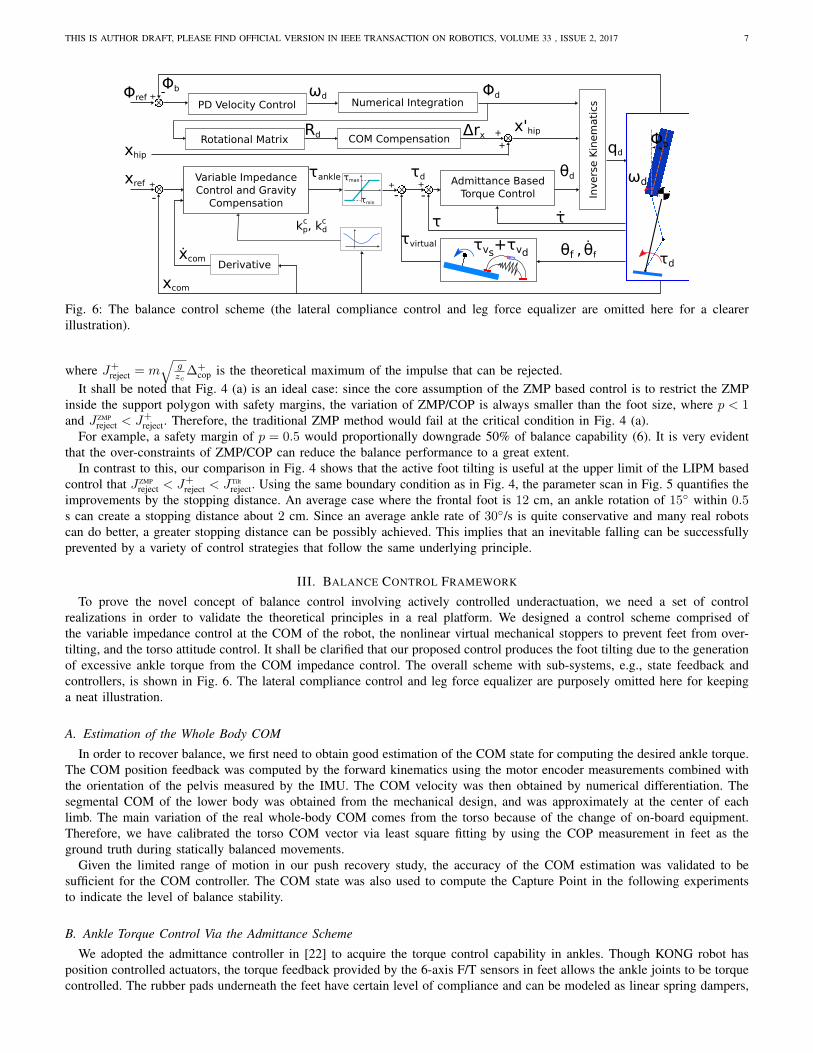
Fig. 6: The balance control scheme (the lateral compliance control and leg force equalizer are omitted here for a clearer
illustration).
where J+
reject = m√
gzc∆+
cop is the theoretical maximum of the impulse that can be rejected.
It shall be noted that Fig. 4 (a) is an ideal case: since the core assumption of the ZMP based control is to restrict the ZMP
inside the support polygon with safety margins, the variation of ZMP/COP is always smaller than the foot size, where p < 1and J ZMP
reject < J+
reject. Therefore, the traditional ZMP method would fail at the critical condition in Fig. 4 (a).
For example, a safety margin of p = 0.5 would proportionally downgrade 50% of balance capability (6). It is very evident
that the over-constraints of ZMP/COP can reduce the balance performance to a great extent.
In contrast to this, our comparison in Fig. 4 shows that the active foot tilting is useful at the upper limit of the LIPM based
control that J ZMP
reject < J+
reject < J Tilt
reject. Using the same boundary condition as in Fig. 4, the parameter scan in Fig. 5 quantifies the
improvements by the stopping distance. An average case where the frontal foot is 12 cm, an ankle rotation of 15◦ within 0.5s can create a stopping distance about 2 cm. Since an average ankle rate of 30◦/s is quite conservative and many real robots
can do better, a greater stopping distance can be possibly achieved. This implies that an inevitable falling can be successfully
prevented by a variety of control strategies that follow the same underlying principle.
III. BALANCE CONTROL FRAMEWORK
To prove the novel concept of balance control involving actively controlled underactuation, we need a set of control
realizations in order to validate the theoretical principles in a real platform. We designed a control scheme comprised of
the variable impedance control at the COM of the robot, the nonlinear virtual mechanical stoppers to prevent feet from over-
tilting, and the torso attitude control. It shall be clarified that our proposed control produces the foot tilting due to the generation
of excessive ankle torque from the COM impedance control. The overall scheme with sub-systems, e.g., state feedback and
controllers, is shown in Fig. 6. The lateral compliance control and leg force equalizer are purposely omitted here for keeping
a neat illustration.
A. Estimation of the Whole Body COM
In order to recover balance, we first need to obtain good estimation of the COM state for computing the desired ankle torque.
The COM position feedback was computed by the forward kinematics using the motor encoder measurements combined with
the orientation of the pelvis measured by the IMU. The COM velocity was then obtained by numerical differentiation. The
segmental COM of the lower body was obtained from the mechanical design, and was approximately at the center of each
limb. The main variation of the real whole-body COM comes from the torso because of the change of on-board equipment.
Therefore, we have calibrated the torso COM vector via least square fitting by using the COP measurement in feet as the
ground truth during statically balanced movements.
Given the limited range of motion in our push recovery study, the accuracy of the COM estimation was validated to be
sufficient for the COM controller. The COM state was also used to compute the Capture Point in the following experiments
to indicate the level of balance stability.
B. Ankle Torque Control Via the Admittance Scheme
We adopted the admittance controller in [22] to acquire the torque control capability in ankles. Though KONG robot has
position controlled actuators, the torque feedback provided by the 6-axis F/T sensors in feet allows the ankle joints to be torque
controlled. The rubber pads underneath the feet have certain level of compliance and can be modeled as linear spring dampers,
THIS IS AUTHOR DRAFT, PLEASE FIND OFFICIAL VERSION IN IEEE TRANSACTION ON ROBOTICS, VOLUME 33 , ISSUE 2, 2017 8
(b) (c)
-τankle-τankle
(a)
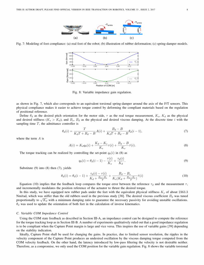
Fig. 7: Modeling of foot compliance: (a) real foot of the robot; (b) illustration of rubber deformation; (c) spring-damper models.
−0.08 −0.04 0.00 0.04 0.08 0.12200
400
600
800
1000
Gain
[Nm
/rad]
kcp
−0.08 −0.04 0.00 0.04 0.08 0.12
Position of COM [m]
135
185
235
285
Gain
[Nm
s/r
ad]
kcd
Fig. 8: Variable impedance gain regulation.
as shown in Fig. 7, which also corresponds to an equivalent torsional spring-damper around the axis of the F/T sensors. This
physical compliance makes it easier to achieve torque control by deforming the compliant materials based on the regulation
of positional reference.
Define θd as the desired pitch orientation for the motor side, τ as the real torque measurement, Ks, Kd as the physical
and desired stiffness (Ks > Kd), and Bs, Bd as the physical and desired viscous damping. At the discrete time i with the
sampling time T , the admittance controller is
θd(i) =T
KdT +Bd −BA(i) +
Bd −B
KdT +Bd −Bθd(i− 1), (7)
where the term A is
A(i) = Kdq0(i) +Kd −Ks
Ks
τ(i) +Bd −B
Ks
τ(i). (8)
The torque tracking can be realized by controlling the set-point q0(i) in (8) as
q0(i) = θd(i− 1)− τ(i)
Ks
+τd(i)
Kd
. (9)
Substitute (9) into (8) then (7), yields
θd(i) = θd(i− 1) +τd(i)− τ(i)
Kd +Bd−Bs
T
+Bd −Bs
Ks(Kd +Bd−Bs
T)τ(i) (10)
Equation (10) implies that the feedback loop compares the torque error between the reference τd and the measurement τ ,
and incrementally modulates the position reference of the actuator to thrust the desired torque.
In this study, we have equipped new rubber pads under the feet with the equivalent physical stiffness Ks of about 2363.3Nm/rad, which was stiffer than the old rubbers used in the previous study [38]. The desired viscous coefficient Bd was tuned
proportionally to√Kd with a minimum damping ratio to guarantee the necessary passivity for avoiding unstable oscillations.
θd was used to update the orientation of both feet in the calculation of inverse kinematics.
C. Variable COM Impedance Control
Using the COM state feedback as described in Section III-A, an impedance control can be designed to compute the reference
for the torque tracking loop as in Section III-B. A number of experiments qualitatively ruled out that a good impedance regulation
is to be compliant when the Capture Point margin is large and vice versa. This inspires the use of variable gains [39] depending
on the stability indication.
Ideally, Capture Point shall be used for changing the gains. In practice, due to limited sensor resolution, the ripples in the
velocity component of the Capture Point produces an undesired oscillation by the viscous damping torque computed from the
COM velocity feedback. On the other hand, the latency introduced by low-pass filtering the velocity is not desirable neither.
Therefore, as a compromise, we only used the COM position for the variable gain regulation. Fig. 8 shows the variable torsional
THIS IS AUTHOR DRAFT, PLEASE FIND OFFICIAL VERSION IN IEEE TRANSACTION ON ROBOTICS, VOLUME 33 , ISSUE 2, 2017 9
-τankle
τankle
-τankle
Variable Impedance Control
Virtual Stopper
θf
τvs+τvd
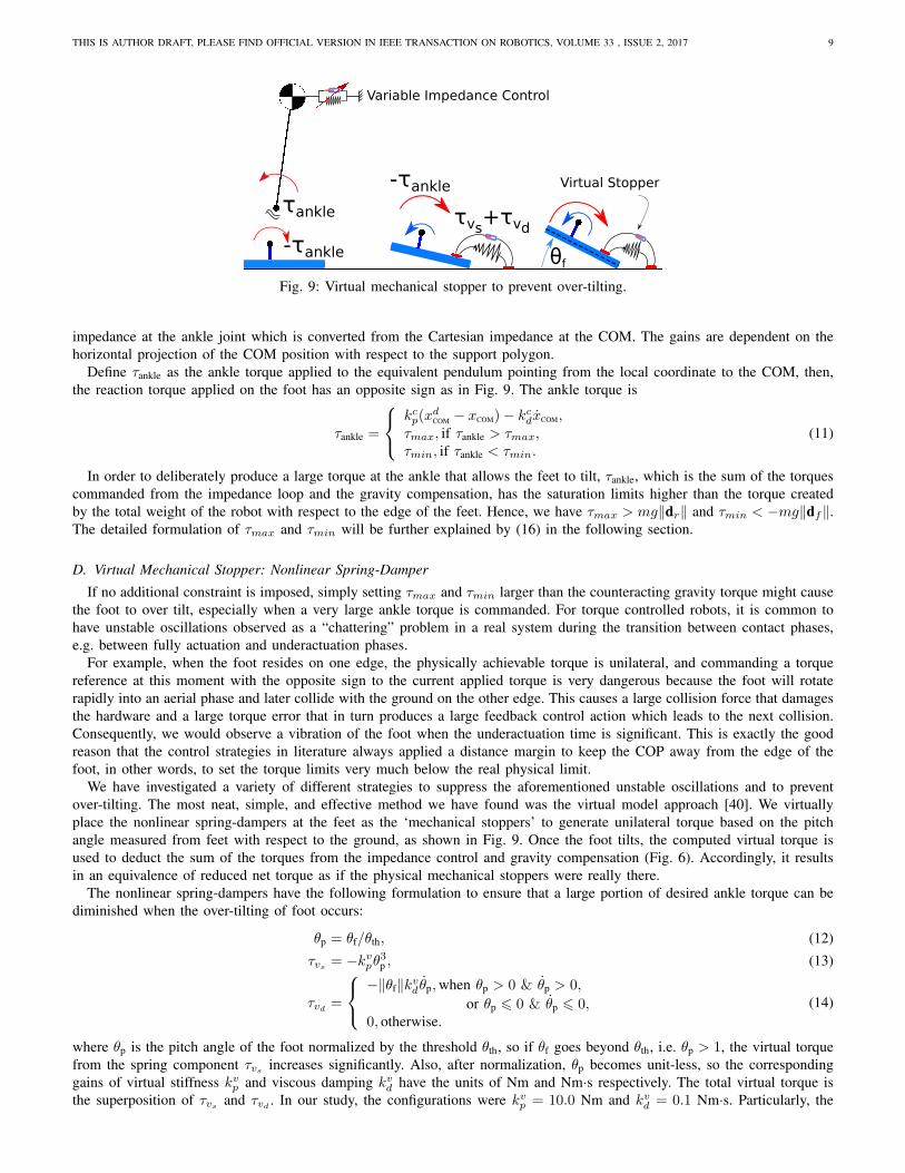
Fig. 9: Virtual mechanical stopper to prevent over-tilting.
impedance at the ankle joint which is converted from the Cartesian impedance at the COM. The gains are dependent on the
horizontal projection of the COM position with respect to the support polygon.
Define τankle as the ankle torque applied to the equivalent pendulum pointing from the local coordinate to the COM, then,
the reaction torque applied on the foot has an opposite sign as in Fig. 9. The ankle torque is
τankle =
kcp(xdCOM
− xCOM)− kcdxCOM,τmax, if τankle > τmax,τmin, if τankle < τmin.
(11)
In order to deliberately produce a large torque at the ankle that allows the feet to tilt, τankle, which is the sum of the torques
commanded from the impedance loop and the gravity compensation, has the saturation limits higher than the torque created
by the total weight of the robot with respect to the edge of the feet. Hence, we have τmax > mg‖dr‖ and τmin < −mg‖df‖.
The detailed formulation of τmax and τmin will be further explained by (16) in the following section.
D. Virtual Mechanical Stopper: Nonlinear Spring-Damper
If no additional constraint is imposed, simply setting τmax and τmin larger than the counteracting gravity torque might cause
the foot to over tilt, especially when a very large ankle torque is commanded. For torque controlled robots, it is common to
have unstable oscillations observed as a “chattering” problem in a real system during the transition between contact phases,
e.g. between fully actuation and underactuation phases.
For example, when the foot resides on one edge, the physically achievable torque is unilateral, and commanding a torque
reference at this moment with the opposite sign to the current applied torque is very dangerous because the foot will rotate
rapidly into an aerial phase and later collide with the ground on the other edge. This causes a large collision force that damages
the hardware and a large torque error that in turn produces a large feedback control action which leads to the next collision.
Consequently, we would observe a vibration of the foot when the underactuation time is significant. This is exactly the good
reason that the control strategies in literature always applied a distance margin to keep the COP away from the edge of the
foot, in other words, to set the torque limits very much below the real physical limit.
We have investigated a variety of different strategies to suppress the aforementioned unstable oscillations and to prevent
over-tilting. The most neat, simple, and effective method we have found was the virtual model approach [40]. We virtually
place the nonlinear spring-dampers at the feet as the ‘mechanical stoppers’ to generate unilateral torque based on the pitch
angle measured from feet with respect to the ground, as shown in Fig. 9. Once the foot tilts, the computed virtual torque is
used to deduct the sum of the torques from the impedance control and gravity compensation (Fig. 6). Accordingly, it results
in an equivalence of reduced net torque as if the physical mechanical stoppers were really there.
The nonlinear spring-dampers have the following formulation to ensure that a large portion of desired ankle torque can be
diminished when the over-tilting of foot occurs:
θp = θf/θth, (12)
τvs= −kvpθ
3p , (13)
τvd=
−‖θf‖kvd θp,when θp > 0 & θp > 0,
or θp 6 0 & θp 6 0,0, otherwise.
(14)
where θp is the pitch angle of the foot normalized by the threshold θth, so if θf goes beyond θth, i.e. θp > 1, the virtual torque
from the spring component τvsincreases significantly. Also, after normalization, θp becomes unit-less, so the corresponding
gains of virtual stiffness kvp and viscous damping kvd have the units of Nm and Nm·s respectively. The total virtual torque is
the superposition of τvsand τvd
. In our study, the configurations were kvp = 10.0 Nm and kvd = 0.1 Nm·s. Particularly, the
THIS IS AUTHOR DRAFT, PLEASE FIND OFFICIAL VERSION IN IEEE TRANSACTION ON ROBOTICS, VOLUME 33 , ISSUE 2, 2017 10
(a) (b)
ml
ml+mf
mb
rb
z
xy
z
xyΣL
Δrxcom
ΣLz
xyΣB
xcom
(c)
θa
Φd-+
θf
-+
Φb
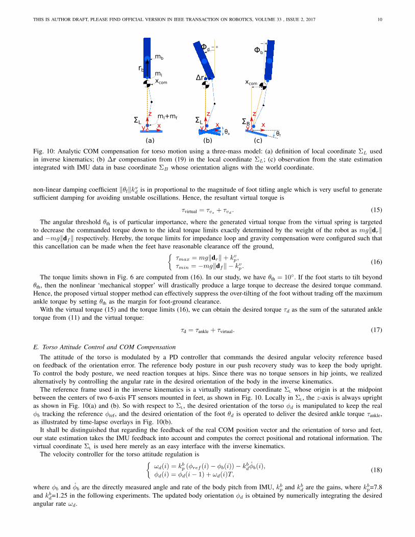
Fig. 10: Analytic COM compensation for torso motion using a three-mass model: (a) definition of local coordinate ΣL used
in inverse kinematics; (b) ∆r compensation from (19) in the local coordinate ΣL; (c) observation from the state estimation
integrated with IMU data in base coordinate ΣB whose orientation aligns with the world coordinate.
non-linear damping coefficient ‖θf‖kvd is in proportional to the magnitude of foot titling angle which is very useful to generate
sufficient damping for avoiding unstable oscillations. Hence, the resultant virtual torque is
τvirtual = τvs+ τvd
. (15)
The angular threshold θth is of particular importance, where the generated virtual torque from the virtual spring is targeted
to decrease the commanded torque down to the ideal torque limits exactly determined by the weight of the robot as mg‖dr‖and −mg‖df‖ respectively. Hereby, the torque limits for impedance loop and gravity compensation were configured such that
this cancellation can be made when the feet have reasonable clearance off the ground,{
τmax = mg‖dr‖+ kvp ,τmin = −mg‖df‖ − kvp .
(16)
The torque limits shown in Fig. 6 are computed from (16). In our study, we have θth = 10◦. If the foot starts to tilt beyond
θth, then the nonlinear ‘mechanical stopper’ will drastically produce a large torque to decrease the desired torque command.
Hence, the proposed virtual stopper method can effectively suppress the over-tilting of the foot without trading off the maximum
ankle torque by setting θth as the margin for foot-ground clearance.
With the virtual torque (15) and the torque limits (16), we can obtain the desired torque τd as the sum of the saturated ankle
torque from (11) and the virtual torque:
τd = τankle + τvirtual. (17)
E. Torso Attitude Control and COM Compensation
The attitude of the torso is modulated by a PD controller that commands the desired angular velocity reference based
on feedback of the orientation error. The reference body posture in our push recovery study was to keep the body upright.
To control the body posture, we need reaction torques at hips. Since there was no torque sensors in hip joints, we realized
alternatively by controlling the angular rate in the desired orientation of the body in the inverse kinematics.
The reference frame used in the inverse kinematics is a virtually stationary coordinate ΣL whose origin is at the midpoint
between the centers of two 6-axis FT sensors mounted in feet, as shown in Fig. 10. Locally in ΣL, the z-axis is always upright
as shown in Fig. 10(a) and (b). So with respect to ΣL, the desired orientation of the torso φd is manipulated to keep the real
φb tracking the reference φref, and the desired orientation of the foot θd is operated to deliver the desired ankle torque τankle,
as illustrated by time-lapse overlays in Fig. 10(b).
It shall be distinguished that regarding the feedback of the real COM position vector and the orientation of torso and feet,
our state estimation takes the IMU feedback into account and computes the correct positional and rotational information. The
virtual coordinate ΣL is used here merely as an easy interface with the inverse kinematics.
The velocity controller for the torso attitude regulation is{
ωd(i) = kbp (φref (i)− φb(i))− kbdφb(i),φd(i) = φd(i− 1) + ωd(i)T,
(18)
where φb and φb are the directly measured angle and rate of the body pitch from IMU, kbp and kbd are the gains, where kbp=7.8
and kbd=1.25 in the following experiments. The updated body orientation φd is obtained by numerically integrating the desired
angular rate ωd.
THIS IS AUTHOR DRAFT, PLEASE FIND OFFICIAL VERSION IN IEEE TRANSACTION ON ROBOTICS, VOLUME 33 , ISSUE 2, 2017 11
To integrate seamlessly two controllers of the COM and the torso attitude, we need to compensate for the COM displacement
caused by the torso orientation control, and eliminate undesired coupling effects that downgrade the performance. Inspired by
the three-mass model in [41], we resolve the mass compensation analytically where the mass of the leg is equally divided and
lumped at the hip and the ankle respectively. The first mass mb is the mass of upper body (torso, pelvis, two arms and the
head); the second ml is the mass of one leg located at the hip; and the third mass mf at the foot is the sum of the mass of
one leg and two feet.
During the standing balance, the feet do not produce a very large range of motion, thus the variation of the mf vector in
ΣL does not affect much the overall COM of the robot thus its effect can be omitted. We focus on the compensation caused
by the major mass mb. Define the COM vector of mb as rb = [xb, yb, zb]T , the objective is to compute the hip compensation
∆r for the change of the COM caused by the rotation of rb, as depicted in Fig. 10(b). The positional compensation ∆r can
be computed analytically as
∆r =mb
mb +ml
(R0 −Rd)rb, (19)
where R0 is initial rotational matrix of the torso and Rd is calculated by φd from (18). ∆r is superimposed to the initial
hip position in ΣL as presented in Fig. 6 and delineated in Fig. 10. In such a way, the total COM remains the same, and the
rotation of the torso does not disturb the effective pendulum pointing from the base frame ΣL to the whole-body COM. Hence,
we guarantee the use of two decoupled controllers for controlling the COM and the torso orientation independently.
F. Lateral Compliance Control and Leg Force Equalizer
Despite the attempt to apply external force sagittally, the real robot has dynamical effects in a 3-D space; thus there exists
coupled disturbances laterally as well. This cross effect can cause some lateral oscillations, particularly the perturbation on the
vertical leg forces. Because ankle torques need to be equally distributed on two feet to use the same torque thresholds τmax
and τmin (16), equal vertical leg forces are required. Otherwise, a foot with a smaller leg force will over tilt whereas the other
with a larger leg force will remain stationary. In this case, it successively creates more unbalanced motion on the lateral plane.
To resolve this issue, we adapted a variant of the compliance control for a stiff system from [22] in a translational form for
stabilizing the lateral motion and damping out undesired disturbances. We also used an additional integral control to equalize
the left/right leg forces. Define ydcop(i) and yrealcop (i) as the desired and measured lateral COP, the compliance control is regulated
by modifying desired hip position by
∆yc(i) =T
KydT +By
d
[yrealcop (i)− ydcop(i)]
+By
d
KydT +By
d
∆yc(i− 1),
(20)
where Kyd and By
d are the desired stiffness and viscous coefficient to realize a compliant behavior. The leg forces are equalized
by the integral control of the filtered force error
∆yi(i) = kyi [flz(i)− fr
z (i)]T +∆yi(i− 1), (21)
where [·] denotes the low-pass filtered signals. In our experiments, we had kyi = 0.0002 that was sufficient to remove the
steady state error of vertical leg forces.
The resulted lateral positional modification ∆yd, therefore, is composed by two terms as
∆yd(i) = ∆yc(i) + ∆yi(i), (22)
where the compliant component ∆yc deals with the external force perturbation and has a relatively high control bandwidth;
the integral component ∆yi moves the COM closer to the leg with less vertical force, where this counterbalancing action is of
a relatively low control bandwidth. For the reason of clarity and readability, the lateral compliance control and the leg force
equalizer are not displayed in Fig. 6.
IV. EXPERIMENTAL VALIDATION
This section presents the validations that benchmark the performance of each sub-system, followed by the demonstrations
of the whole control framework such that the method can be best replicated by other robotics researchers.
THIS IS AUTHOR DRAFT, PLEASE FIND OFFICIAL VERSION IN IEEE TRANSACTION ON ROBOTICS, VOLUME 33 , ISSUE 2, 2017 12
0 20 40 60 80 100 120 140 160 180 200 220 240 260Time [s]
0.06
0.04
0.02
0.00
0.02
0.04
0.06
Posi
tion
[m]
COMCOP
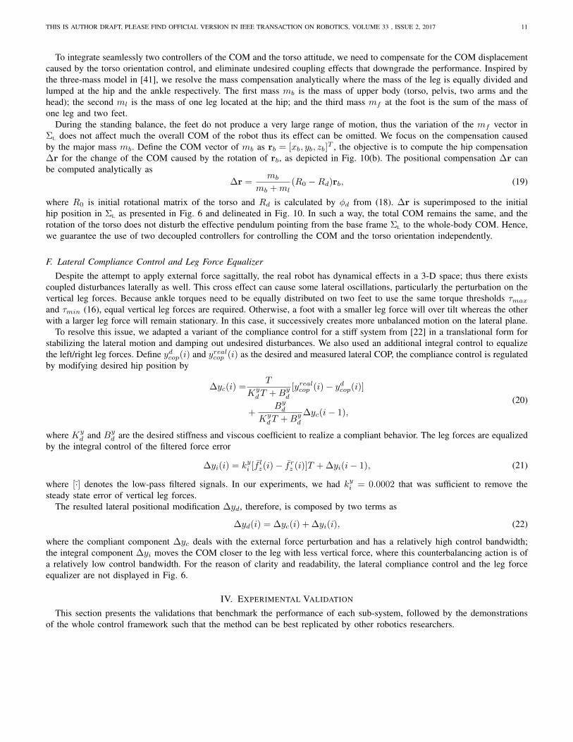
Fig. 11: Validation of COM estimation xCOM based on COP measurement xCOP during statically balanced motion in the sagittal
plane.
0.015 0.010 0.005 0.000 0.005 0.010 0.0154530150
153045
τ total
0.015 0.010 0.005 0.000 0.005 0.010 0.0154530150
153045
Torq
ue [N
m]
τ spring
0.015 0.010 0.005 0.000 0.005 0.010 0.015θf [rad]
106226
10τ damping
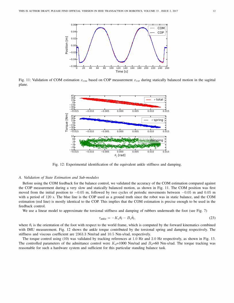
Fig. 12: Experimental identification of the equivalent ankle stiffness and damping.
A. Validation of State Estimation and Sub-modules
Before using the COM feedback for the balance control, we validated the accuracy of the COM estimation compared against
the COP measurement during a very slow and statically balanced motion, as shown in Fig. 11. The COM position was first
moved from the initial position to −0.05 m, followed by two cycles of periodic movements between −0.05 m and 0.05 m
with a period of 120 s. The blue line is the COP used as a ground truth since the robot was in static balance, and the COM
estimation (red line) is mostly identical to the COP. This implies that the COM estimation is precise enough to be used in the
feedback control.
We use a linear model to approximate the torsional stiffness and damping of rubbers underneath the foot (see Fig. 7)
τankle = −Ksθf −Bsθf, (23)
where θf is the orientation of the foot with respect to the world frame, which is computed by the forward kinematics combined
with IMU measurement. Fig. 12 shows the ankle torque contributed by the torsional spring and damping respectively. The
stiffness and viscous coefficient are 2363.3 Nm/rad and 10.5 Nm·s/rad, respectively.
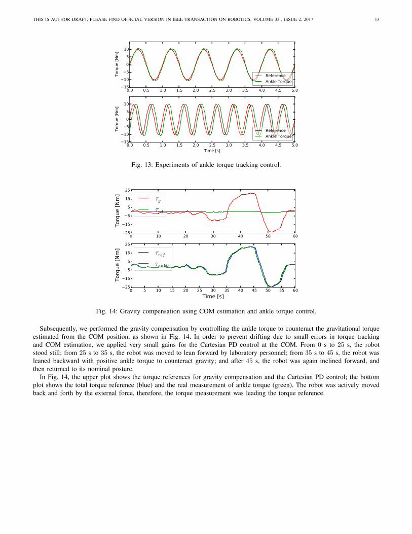
The torque control using (10) was validated by tracking references at 1.0 Hz and 2.0 Hz respectively, as shown in Fig. 13.
The controlled parameters of the admittance control were Kd=1000 Nm/rad and Bd=60 Nm·s/rad. The torque tracking was
reasonable for such a hardware system and sufficient for this particular standing balance task.
THIS IS AUTHOR DRAFT, PLEASE FIND OFFICIAL VERSION IN IEEE TRANSACTION ON ROBOTICS, VOLUME 33 , ISSUE 2, 2017 13
0.0 0.5 1.0 1.5 2.0 2.5 3.0 3.5 4.0 4.5 5.01510
505
10
Torq
ue [N
m]
ReferenceAnkle Torque
0.0 0.5 1.0 1.5 2.0 2.5 3.0 3.5 4.0 4.5 5.0Time [s]
1510
505
10
Torq
ue [N
m]
ReferenceAnkle Torque
Fig. 13: Experiments of ankle torque tracking control.
0 10 20 30 40 50 6025
15
5
5
15
25
Torq
ue [N
m]
τg
τpd
0 5 10 15 20 25 30 35 40 45 50 55 60Time [s]
25
15
5
5
15
25
Torq
ue [N
m]
τref
τankle
Fig. 14: Gravity compensation using COM estimation and ankle torque control.
Subsequently, we performed the gravity compensation by controlling the ankle torque to counteract the gravitational torque
estimated from the COM position, as shown in Fig. 14. In order to prevent drifting due to small errors in torque tracking
and COM estimation, we applied very small gains for the Cartesian PD control at the COM. From 0 s to 25 s, the robot
stood still; from 25 s to 35 s, the robot was moved to lean forward by laboratory personnel; from 35 s to 45 s, the robot was
leaned backward with positive ankle torque to counteract gravity; and after 45 s, the robot was again inclined forward, and
then returned to its nominal posture.
In Fig. 14, the upper plot shows the torque references for gravity compensation and the Cartesian PD control; the bottom
plot shows the total torque reference (blue) and the real measurement of ankle torque (green). The robot was actively moved
back and forth by the external force, therefore, the torque measurement was leading the torque reference.
THIS IS AUTHOR DRAFT, PLEASE FIND OFFICIAL VERSION IN IEEE TRANSACTION ON ROBOTICS, VOLUME 33 , ISSUE 2, 2017 14
0 50 100 150 200 2500.04
0.00
0.04
Posi
tion
[m] xCOM w/o compensation
xCOM w/ compensation
0 50 100 150 200 250Time [s]
10505
1015
Angl
e [d
eg] φb w/o compensation
φb w/ compensation
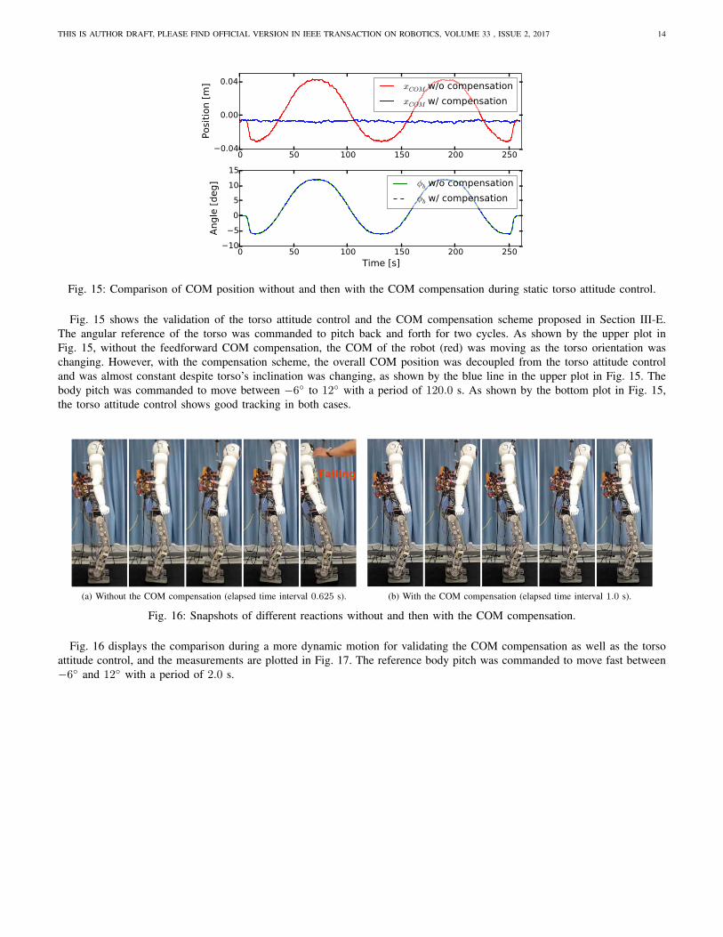
Fig. 15: Comparison of COM position without and then with the COM compensation during static torso attitude control.
Fig. 15 shows the validation of the torso attitude control and the COM compensation scheme proposed in Section III-E.
The angular reference of the torso was commanded to pitch back and forth for two cycles. As shown by the upper plot in
Fig. 15, without the feedforward COM compensation, the COM of the robot (red) was moving as the torso orientation was
changing. However, with the compensation scheme, the overall COM position was decoupled from the torso attitude control
and was almost constant despite torso’s inclination was changing, as shown by the blue line in the upper plot in Fig. 15. The
body pitch was commanded to move between −6◦ to 12◦ with a period of 120.0 s. As shown by the bottom plot in Fig. 15,
the torso attitude control shows good tracking in both cases.
(a) Without the COM compensation (elapsed time interval 0.625 s). (b) With the COM compensation (elapsed time interval 1.0 s).
Fig. 16: Snapshots of different reactions without and then with the COM compensation.
Fig. 16 displays the comparison during a more dynamic motion for validating the COM compensation as well as the torso
attitude control, and the measurements are plotted in Fig. 17. The reference body pitch was commanded to move fast between
−6◦ and 12◦ with a period of 2.0 s.
THIS IS AUTHOR DRAFT, PLEASE FIND OFFICIAL VERSION IN IEEE TRANSACTION ON ROBOTICS, VOLUME 33 , ISSUE 2, 2017 15
0 1 2 3 4 5 6 7 8 9 100.10
0.05
0.00
0.05
0.10
Posi
tion
[m] xCOP
xCOM
0 1 2 3 4 5 6 7 8 9 100.065
0.045
0.025
0.005
0.015
0.035
Posi
tion
[m] ∆xhip
105
051015
Angl
e [d
eg]
φb
(a) Without the COM compensation.
0 5 10 15 20 25 300.0400.0250.0100.0050.0200.0350.050
Posi
tion
[m] xCOP
xCOM
0 5 10 15 20 25 300.0650.0450.0250.0050.0150.035
Posi
tion
[m] ∆xhip
7
2
3
8
13
Angl
e [d
eg]
φb
(b) With the COM compensation.
Fig. 17: Comparison of COM position without and then with the COM compensation during dynamic torso attitude control.
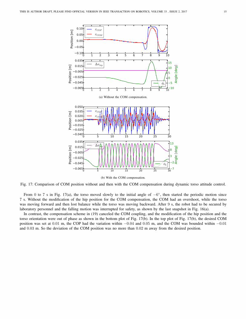
From 0 to 7 s in Fig. 17(a), the torso moved slowly to the initial angle of −6◦, then started the periodic motion since
7 s. Without the modification of the hip position for the COM compensation, the COM had an overshoot, while the torso
was moving forward and then lost balance while the torso was moving backward. After 9 s, the robot had to be secured by
laboratory personnel and the falling motion was interrupted for safety, as shown by the last snapshot in Fig. 16(a).
In contrast, the compensation scheme in (19) canceled the COM coupling, and the modification of the hip position and the
torso orientation were out of phase as shown in the bottom plot of Fig. 17(b). In the top plot of Fig. 17(b), the desired COM
position was set at 0.01 m, the COP had the variation within −0.04 and 0.05 m, and the COM was bounded within −0.01and 0.03 m. So the deviation of the COM position was no more than 0.02 m away from the desired position.
THIS IS AUTHOR DRAFT, PLEASE FIND OFFICIAL VERSION IN IEEE TRANSACTION ON ROBOTICS, VOLUME 33 , ISSUE 2, 2017 16
0 5 10 15 20 25 30 35Time [s]
80
30
20
70
120
170
220
270
Forc
e [N
]
Fz leftFz rightFx leftFx right
Fig. 18: Validation of vertical leg force control.
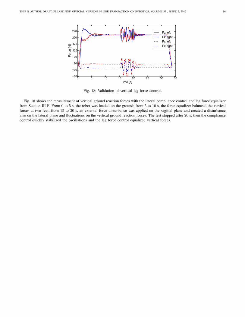
Fig. 18 shows the measurement of vertical ground reaction forces with the lateral compliance control and leg force equalizer
from Section III-F. From 0 to 5 s, the robot was loaded on the ground; from 5 to 10 s, the force equalizer balanced the vertical
forces at two feet; from 15 to 20 s, an external force disturbance was applied on the sagittal plane and created a disturbance
also on the lateral plane and fluctuations on the vertical ground reaction forces. The test stopped after 20 s; then the compliance
control quickly stabilized the oscillations and the leg force control equalized vertical forces.
THIS IS AUTHOR DRAFT, PLEASE FIND OFFICIAL VERSION IN IEEE TRANSACTION ON ROBOTICS, VOLUME 33 , ISSUE 2, 2017 17
B. Balance Recovery with Under-actuation Phase
(a) Balance recovery after a forward push.
(b) Balance recovery after a backward push.
Fig. 19: Experiments of push recovery with active control of underactuation (snapshots start at the beginning of foot tilting
and are spaced at 1/6s time interval).
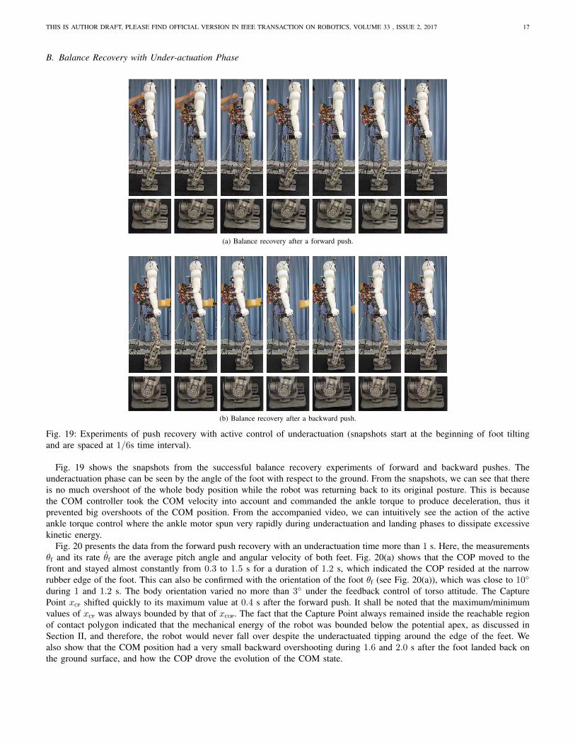
Fig. 19 shows the snapshots from the successful balance recovery experiments of forward and backward pushes. The
underactuation phase can be seen by the angle of the foot with respect to the ground. From the snapshots, we can see that there
is no much overshoot of the whole body position while the robot was returning back to its original posture. This is because
the COM controller took the COM velocity into account and commanded the ankle torque to produce deceleration, thus it
prevented big overshoots of the COM position. From the accompanied video, we can intuitively see the action of the active
ankle torque control where the ankle motor spun very rapidly during underactuation and landing phases to dissipate excessive
kinetic energy.
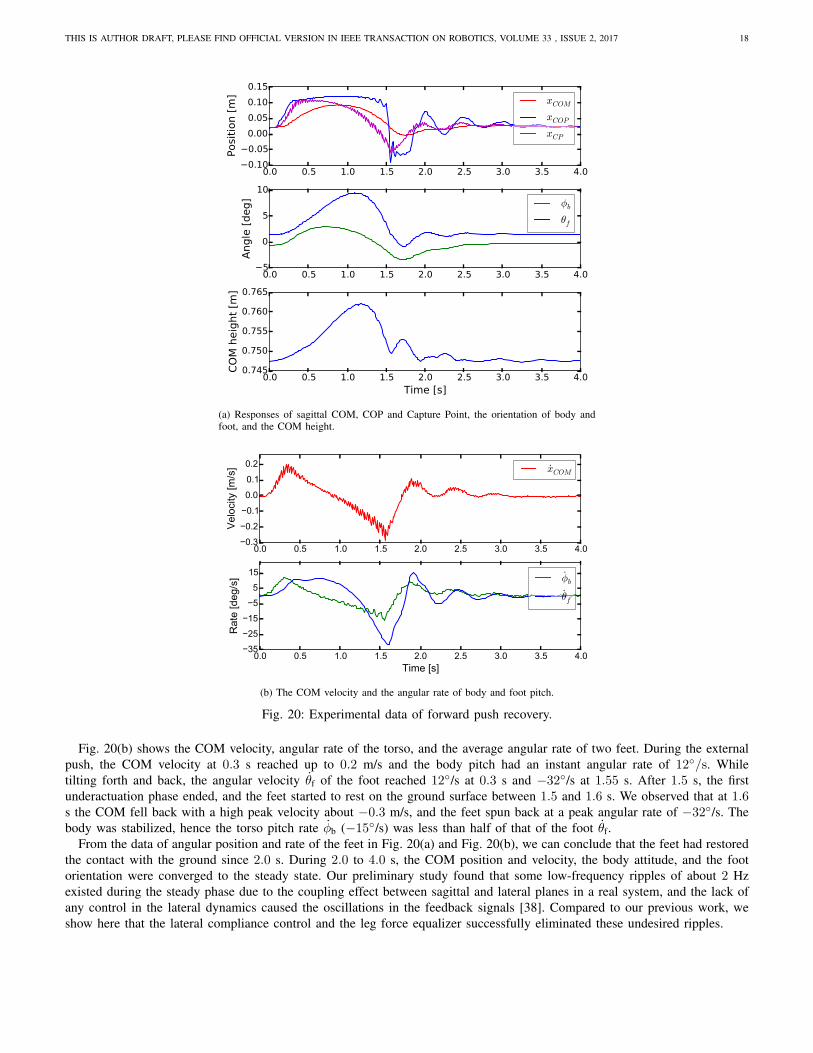
Fig. 20 presents the data from the forward push recovery with an underactuation time more than 1 s. Here, the measurements
θf and its rate θf are the average pitch angle and angular velocity of both feet. Fig. 20(a) shows that the COP moved to the
front and stayed almost constantly from 0.3 to 1.5 s for a duration of 1.2 s, which indicated the COP resided at the narrow
rubber edge of the foot. This can also be confirmed with the orientation of the foot θf (see Fig. 20(a)), which was close to 10◦
during 1 and 1.2 s. The body orientation varied no more than 3◦ under the feedback control of torso attitude. The Capture
Point xCP shifted quickly to its maximum value at 0.4 s after the forward push. It shall be noted that the maximum/minimum
values of xCP was always bounded by that of xCOP. The fact that the Capture Point always remained inside the reachable region
of contact polygon indicated that the mechanical energy of the robot was bounded below the potential apex, as discussed in
Section II, and therefore, the robot would never fall over despite the underactuated tipping around the edge of the feet. We
also show that the COM position had a very small backward overshooting during 1.6 and 2.0 s after the foot landed back on
the ground surface, and how the COP drove the evolution of the COM state.
THIS IS AUTHOR DRAFT, PLEASE FIND OFFICIAL VERSION IN IEEE TRANSACTION ON ROBOTICS, VOLUME 33 , ISSUE 2, 2017 18
0.0 0.5 1.0 1.5 2.0 2.5 3.0 3.5 4.00.100.050.000.050.100.15
Posi
tion
[m] xCOM
xCOP
xCP
0.0 0.5 1.0 1.5 2.0 2.5 3.0 3.5 4.05
0
5
10
Angl
e [d
eg] φb
θf
0.0 0.5 1.0 1.5 2.0 2.5 3.0 3.5 4.0Time [s]
0.745
0.750
0.755
0.760
0.765
COM
hei
ght [
m]
(a) Responses of sagittal COM, COP and Capture Point, the orientation of body andfoot, and the COM height.
0.0 0.5 1.0 1.5 2.0 2.5 3.0 3.5 4.00.3
0.2
0.1
0.0
0.1
0.2
Velo
city
[m/s
] xCOM
0.0 0.5 1.0 1.5 2.0 2.5 3.0 3.5 4.0Time [s]
352515
55
15
Rat
e [d
eg/s
] φb
θf
(b) The COM velocity and the angular rate of body and foot pitch.
Fig. 20: Experimental data of forward push recovery.
Fig. 20(b) shows the COM velocity, angular rate of the torso, and the average angular rate of two feet. During the external
push, the COM velocity at 0.3 s reached up to 0.2 m/s and the body pitch had an instant angular rate of 12◦/s. While
tilting forth and back, the angular velocity θf of the foot reached 12◦/s at 0.3 s and −32◦/s at 1.55 s. After 1.5 s, the first
underactuation phase ended, and the feet started to rest on the ground surface between 1.5 and 1.6 s. We observed that at 1.6s the COM fell back with a high peak velocity about −0.3 m/s, and the feet spun back at a peak angular rate of −32◦/s. The
body was stabilized, hence the torso pitch rate φb (−15◦/s) was less than half of that of the foot θf.
From the data of angular position and rate of the feet in Fig. 20(a) and Fig. 20(b), we can conclude that the feet had restored
the contact with the ground since 2.0 s. During 2.0 to 4.0 s, the COM position and velocity, the body attitude, and the foot
orientation were converged to the steady state. Our preliminary study found that some low-frequency ripples of about 2 Hz
existed during the steady phase due to the coupling effect between sagittal and lateral planes in a real system, and the lack of
any control in the lateral dynamics caused the oscillations in the feedback signals [38]. Compared to our previous work, we
show here that the lateral compliance control and the leg force equalizer successfully eliminated these undesired ripples.
THIS IS AUTHOR DRAFT, PLEASE FIND OFFICIAL VERSION IN IEEE TRANSACTION ON ROBOTICS, VOLUME 33 , ISSUE 2, 2017 19
0.0 0.5 1.0 1.5 2.0 2.5 3.0 3.5 4.0Time [s]
70
60
50
40
30
20
10
0
Forc
e [N
]Fext
Fig. 21: External force measured in backward push recovery.
0.0 0.5 1.0 1.5 2.0 2.5 3.0 3.5 4.00.100.050.000.050.100.15
Posi
tion
[m] xCOM
xCOP
xCP
0.0 0.5 1.0 1.5 2.0 2.5 3.0 3.5 4.010
5
0
5
Angl
e [d
eg] φb
θf
0.0 0.5 1.0 1.5 2.0 2.5 3.0 3.5 4.0Time [s]
0.7450.7500.7550.7600.7650.770
COM
hei
ght [
m]
(a) Responses of sagittal COM, COP and Capture Point, the orientation of body andfoot, and the COM height.
0.0 0.5 1.0 1.5 2.0 2.5 3.0 3.5 4.00.250.150.050.050.150.25
Velo
city
[m/s
] xCOM
0.0 0.5 1.0 1.5 2.0 2.5 3.0 3.5 4.0Time [s]
20100
10203040
Rat
e [d
eg/s
] φb
θf
(b) The COM velocity and the angular rate of body and foot pitch.
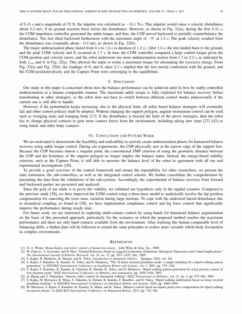
Fig. 22: Experimental data of backward push recovery.
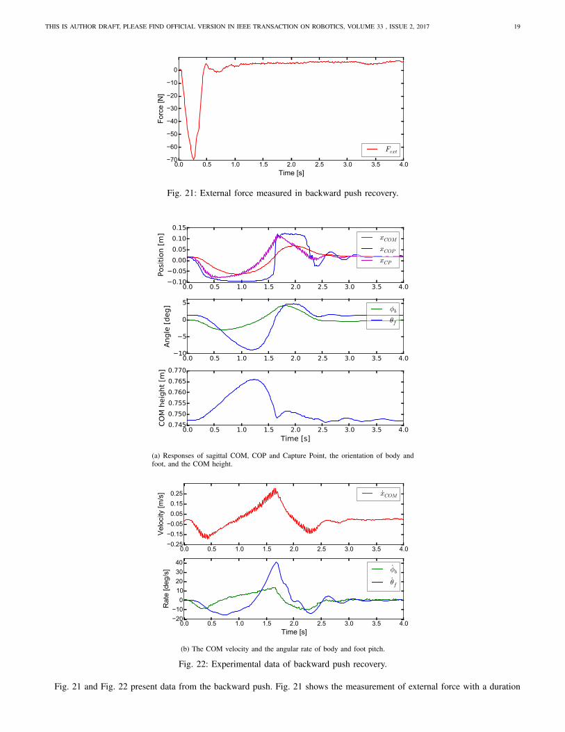
Fig. 21 and Fig. 22 present data from the backward push. Fig. 21 shows the measurement of external force with a duration
THIS IS AUTHOR DRAFT, PLEASE FIND OFFICIAL VERSION IN IEEE TRANSACTION ON ROBOTICS, VOLUME 33 , ISSUE 2, 2017 20
of 0.45 s and a magnitude of 70 N, the impulse was calculated as −16.1 N·s. This impulse would cause a velocity disturbance
about 0.3 m/s, if no ground reaction force resists the disturbance. However, as shown in Fig. 22(a), during the first 0.45 s,
the COM impedance controller generated the ankle torque, and thus, the COP moved backward to partially counterbalance the
disturbance. The feet tilted backward furthermore with the maximum angle of −9◦ at 1.2 s. The peak velocity resulted from
the disturbance was eventually about −0.2 m/s, as shown in Fig. 22(b).
The major underactuation phase lasted from 0.4 to 1.6 s (a duration of 1.2 s). After 1.6 s, the feet landed back to the ground,
and the peak COM velocity and θf occurred at 1.7 s. In turn, the COM controller computed a large control torque given the
COM position and velocity errors, and the robot underwent one more underactuation motion from 1.7 to 2.2 s, as indicated by
both xCOP and θf in Fig. 22(a). This allowed the ankle to retain a maximum torque for attenuating the excessive energy. From
Fig. 22(a) and Fig. 22(b), the readings of θf and θf since 2.5 s implied that the feet mostly conformed with the ground, and
the COM position/velocity and the Capture Point were converging to the equilibrium.
V. DISCUSSION
Our study in this paper is concerned about how the balance performance can be achieved until its best by stably controlled
underactuation in a human comparable manner. The maximum ankle torque is fully exploited for balance recovery before
transitioning to other strategies, so the robot does not have to switch between different control modes unnecessarily if the
current one is still able to handle.
However, if the perturbation keeps increasing, due to the physical limit, all ankle based balance strategies will eventually
fail and other control policies shall be adopted. Without changing the support polygon, angular momentum control can be used
such as swinging arms and lounging body [17]. If the disturbance is beyond the limit of the above strategies, then the robot
has to change physical contacts to gain more contact forces from the environment, including taking new steps [27] [42] or
using hands and other body contacts.
VI. CONCLUSION AND FUTURE WORK
We are motivated to demonstrate the feasibility and realizability to actively create underactuation phases for humanoid balance
recovery using ankle torque control. During our experiments, the COP physically acts at the narrow edge of the support feet.
Because the COP becomes almost a singular point, the conventional ZMP criterion of using the geometric distance between
the COP and the boundary of the support polygon no longer implies the balance status. Instead, the energy-based stability
criterion, such as the Capture Point, is still able to measure the balance level of the robot in agreement with all our real
experimental investigations [38].
To provide a good overview of the control framework and ensure the repeatability for other researchers, we present the
state estimation, the sub-controllers, as well as the integrated control scheme. We further consolidate the comprehension by
presenting the data from the validations of the sub-systems. Accordingly, the experimental of balance recovery from forward
and backward pushes are presented and analyzed.
Since the goal of our study is to prove the viability, we validated our hypothesis only in the sagittal scenario. Compared to
the previous study [38], we have improved the COM control using a three-mass model to analytically resolve the hip position
compensation for canceling the torso mass variation during large motions. To cope with the undesired lateral disturbance due
to dynamical coupling, as found in [38], we have implemented compliance control and leg force control that significantly
improve the performance during steady state.
For future work, we are interested in exploring multi-contact control by using hands for humanoid balance augmentation
on the basis of this presented approach, particularly for the scenarios in which the proposed method reaches the maximum
performance and there are only hand contacts available from the environment. After realizing this human comparable level of
balancing skills, a further plan will be followed to extend the same principles to realize more versatile whole-body locomotion
in complex environments.
REFERENCES
[1] D. A. Winter, Biomechanics and motor control of human movement. John Wiley & Sons, Inc., 2009.[2] M. Popovic, A. Goswami, and H. Herr, “Ground Reference Points in Legged Locomotion: Definitions, Biological Trajectories and Control Implications,”
The International Journal of Robotics Research, vol. 24, no. 12, pp. 1013–1032, Dec. 2005.[3] S. Kajita, H. Hirukawa, K. Harada, and K. Yokoi, Introduction to humanoid robotics. Springer, 2014, vol. 101.[4] S. Kajita, F. Kanehiro, K. Kaneko, K. Yokoi, and H. Hirukawa, “The 3d linear inverted pendulum mode: a simple modeling for a biped walking pattern
generation,” in IEEE/RSJ International Conference on Intelligent Robots and Systems, vol. 1, 2001, pp. 239 –246.[5] S. Kajita, F. Kanehiro, K. Kaneko, K. Fujiwara, K. Harada, K. Yokoi, and H. Hirukawa, “Biped walking pattern generation by using preview control of
zero-moment point,” IEEE International Conference on Robotics and Automation, pp. 1620–1626, 2003.[6] Q. Huang and Y. Nakamura, “Sensory reflex control for humanoid walking,” IEEE Transactions on Robotics, vol. 21, no. 5, pp. 977–984, 2005.[7] S. Kajita, M. Morisawa, K. Miura, S. Nakaoka, K. Harada, K. Kaneko, F. Kanehiro, and K. Yokoi, “Biped walking stabilization based on linear inverted
pendulum tracking,” in IEEE/RSJ International Conference on Intelligent Robots and Systems, 2010, pp. 4489–4496.[8] M. Morisawa, S. Kajita, F. Kanehiro, K. Kaneko, K. Miura, and K. Yokoi, “Balance control based on capture point error compensation for biped walking
on uneven terrain,” in IEEE-RAS International Conference on Humanoid Robots, 2012, pp. 734–740.
THIS IS AUTHOR DRAFT, PLEASE FIND OFFICIAL VERSION IN IEEE TRANSACTION ON ROBOTICS, VOLUME 33 , ISSUE 2, 2017 21
[9] T. McGeer, “Passive dynamic walking,” International Journal of Robotics Research (Special Issue on Legged Locomotion), vol. 9, no. 2, pp. 62–82,1990.
[10] S. H. Collins, A. Ruina, R. Tedrake, and M. Wisse, “Efficient bipedal robots based on passive-dynamic walkers,” Science, vol. 18, no. 307, pp. 1082–1085,February 2005.
[11] J. Pratt, J. Carff, S. Drakunov, and A. Goswami, “Capture point: A step toward humanoid push recovery,” in IEEE-RAS International Conference on
Humanoid Robots, December 2006, pp. 200–207.[12] D. Wight, E. Kubica, and D. Wang, “Introduction of the foot placement estimator: A dynamic measure of balance for bipedal robotics,” Journal of
Computational and Nonlinear Dynamics, vol. 3, no. 1, pp. 011 009–011 019, 2008.[13] Z. Li, C. Zhou, J. Castano, X. Wang, F. Negrello, N. G. Tsagarakis, and D. G. Caldwell, “Fall Prediction of Legged Robots Based on Energy State
and Its Implication of Balance Augmentation: A Study on the Humanoid,” in IEEE International Conference on Robotics and Automation, 2015, pp.5094–5100.
[14] J. Englsberger, C. Ott, and A. Albu-Schaffer, “Three-dimensional bipedal walking control based on divergent component of motion,” IEEE Transactions
on Robotics, vol. 31, no. 2, pp. 355–368, 2015.[15] S. Hyon, J. Hale, and G. Cheng, “Full-body compliant human-humanoid interaction: Balancing in the presence of unknown external forces,” IEEE
Transactions on Robotics, vol. 23, no. 5, pp. 884–898, 2007.[16] L. Sentis, J. Park, and O. Khatib, “Compliant control of multicontact and center-of-mass behaviors in humanoid robots,” IEEE Transactions on Robotics,
vol. 26, no. 3, pp. 483–501, 2010.[17] A. Hofmann, S. Massaquoi, M. Popovic, and H. Herr, “A sliding controller for bipedal balancing using integrated movement of contact and non-contact
limbs,” in IEEE/RSJ International Conference on Intelligent Robots and Systems, vol. 2, 2004, pp. 1952–1959.[18] C. G. Atkeson and B. Stephens, “Multiple balance strategies from one optimization criterion,” in IEEE-RAS International Conference on Humanoid
Robots, 2007, pp. 57–64.[19] D. Braun and M. Goldfarb, “A control approach for actuated dynamic walking in biped robots,” IEEE Transactions on Robotics, vol. 25, no. 6, pp.
1292–1303, 2009.[20] F. Asano, M. Yamakita, N. Kamamichi, and Z.-W. Luo, “A novel gait generation for biped walking robots based on mechanical energy constraint,” IEEE
Transactions on Robotics and Automation, vol. 20, no. 3, pp. 565–573, 2004.[21] S. Anderson, M. Wisse, C. Atkeson, J. Hodgins, G. Zeglin, and B. Moyer, “Powered bipeds based on passive dynamic principles,” in IEEE-RAS
International Conference on Humanoid Robots, December 2005, pp. 110 – 116.[22] Z. Li, C. Zhou, N. Tsagarakis, and D. Caldwell, “Compliance control for stabilizing the humanoid on the changing slope based on terrain inclination
estimation,” Autonomous Robots, pp. 1–17, 2015.[23] D. N. Nenchev and A. Nishio, “Ankle and hip strategies for balance recovery of a biped subjected to an impact,” Robotica, vol. 26, no. 5, pp. 643–653,
2008.[24] Y. Wang, R. Xiong, Q. Zhu, and J. Chu, “Compliance control for standing maintenance of humanoid robots under unknown external disturbances,” in
IEEE International Conference on Robotics and Automation, 2014, pp. 2297–2304.[25] C. Runge, C. Shupert, F. Horak, and F. Zajac, “Ankle and hip postural strategies defined by joint torques,” Gait & Posture, vol. 10, no. 2, pp. 161–170,
1999.[26] C. Ott, M. Roa, and G. Hirzinger, “Posture and balance control for biped robots based on contact force optimization,” in IEEE-RAS International
Conference on Humanoid Robots, Bled, Slovenia, 2011, pp. 26–33.[27] B. Stephens, “Push recovery control for force-controlled humanoid robots,” Ph.D. dissertation, Carnegie Mellon University Pittsburgh, Pennsylvania
USA, 2011.[28] K. Mitobe, M. Satoh, and G. Capi, “A ZMP control of a powered passive dynamic walking robot,” in World Automation Congress (WAC), 2010, pp.
1–7.[29] K. Mitobe, G. Capi, and Y. Nasu, “Control of walking robots based on manipulation of the zero moment point,” Robotica, vol. 18, no. 06, pp. 651–657,
2000.[30] T. Sugihara, T., Y. Nakamura, and H. Inoue, “Real-time humanoid motion generation through ZMP manipulation based on inverted pendulum control,”
in IEEE International Conference on Robotics and Automation, vol. 2, 2002, pp. 1404–1409.[31] T. Sugihara, “Standing stabilizability and stepping maneuver in planar bipedalism based on the best COM-ZMP regulator,” IEEE International Conference
on Robotics and Automation, pp. 1966–1971, May 2009.[32] D. A. Winter, “Human balance and posture control during standing and walking,” Gait & posture, vol. 3, no. 4, pp. 193–214, 1995.[33] “Dexter evolved balancer,” [Online; last accessed 08-March-2016]. [Online]. Available: https://www.youtube.com/user/1859laboratories[34] P. G. Adamczyk, S. H. Collins, and A. D. Kuo, “The advantages of a rolling foot in human walking,” Journal of Experimental Biology, vol. 209, no. 20,
pp. 3953–3963, 2006.[35] P. Sardain and G. Bessonnet, “Forces acting on a biped robot. center of pressure-zero moment point,” IEEE Transactions on Systems, Man and Cybernetics,
Part A: Systems and Humans, vol. 34, no. 5, pp. 630–637, 2004.[36] M. Vukobratovic and B. Borovac, “Zero-moment point - thirty five years of its life,” International Journal of Humanoid Robotics, vol. 1, pp. 157–173,
2004.[37] J. Pratt and R. Tedrake, “Velocity-based stability margins for fast bipedal walking,” Fast Motions in Biomechanics and Robotics, pp. 299–324, 2006.[38] Z. Li, C. Zhou, Q. Zhu, R. Xiong, N. Tsagarakis, and D. Caldwell, “Active control of under-actuated foot tilting for humanoid push recovery,” in
IEEE/RSJ International Conference on Intelligent Robots and Systems, 2015.[39] A. Albu-Schaffer, C. Ott, and G. Hirzinger, “A unified passivity-based control framework for position, torque and impedance control of flexible joint
robots,” The International Journal of Robotics Research, vol. 26, no. 1, pp. 23–39, 2007.[40] J. Pratt, C. M. Chew, A. Torres, P. Dilworth, and G. Pratt, “Virtual Model Control: An Intuitive Approach for Bipedal Locomotion,” The International
Journal of Robotics Research, vol. 20, no. 2, pp. 129–143, 2001.[41] T. Takenaka, T. Matsumoto, and T. Yoshiike, “Real time motion generation and control for biped robot -1st report: Walking gait pattern generation-,” in
IEEE/RSJ International Conference on Intelligent Robots and Systems, Oct 2009, pp. 1084–1091.[42] J. Urata, K. Nshiwaki, Y. Nakanishi, K. Okada, S. Kagami, and M. Inaba, “Online decision of foot placement using singular LQ preview regulation,”
in IEEE-RAS International Conference on Humanoid Robots, 2011, pp. 13–18.

THIS IS AUTHOR DRAFT, PLEASE FIND OFFICIAL VERSION IN IEEE TRANSACTION ON ROBOTICS, VOLUME 33 , ISSUE 2, 2017 22
Zhibin LI graduated from Harbin Institute of Technology (HIT), Harbin, China, with the excellent graduate award in 2007 andreceived the PhD degree in Robotics from Italian Institute of Technology (IIT), Genova, Italy, in 2012.
He is an assistant professor in the School of Informatics and the Deputy of University of Edinburgh, Edinburgh, UK, for theEPSRC UK Robotics and Autonomous Systems Network. His general research interests include the control of dynamical systems,with expertise in legged locomotion, and his current work involves dynamic walking, balancing, stabilization, and torque/impedancecontrol of humanoid robots.
Chengxu ZHOU received his bachelor’s degree in mechanical engineering and automation from Northeastern University, China, in2007; the master’s degree in mechanical engineering from Yamaguchi University, Japan, in 2010; and the PhD degree in Roboticsfrom Italian Institute of Technology (IIT), Genova, Italy, in 2016.
He is a postdoctoral researcher in the Department of Advanced Robotics, IIT. His research interests include dynamic walking andbalancing control of humanoid robots.
Qiuguo ZHU received the B.Sc. degree in mechatronic engineering and the M.Sc. degree in control science and engineering fromZhejiang University, Hanghzou, China, in 2008 and 2011 respectively.
He is with the State Key Laboratory of Industrial Control Technology (SKLICT), Zhejiang University. His research interests involveseries elastic actuator (SEA), dynamic walking, running, balancing, and motion planning of legged robots.
Rong XIONG received the B.Sc. and M.Sc. degrees in computer science and engineering from Zhejiang University, Hangzhou,China, in 1994 and 1997, respectively, and the Ph.D degree in control science and engineering in 2009, all from Zhejiang University,Hangzhou, China.
She has been with the State Key Laboratory of Industrial Control Technology (SKLICT), Zhejiang University, since 1997, whereshe is currently a Professor and the director of the Robotics Laboratory. Her research interests include robotics, with a main focuson humanoid robot, environment mapping, and machine vision.
View publication statsView publication stats