Hub Service Manual - Chris King - Handmade in Portland, OR · Hub Service Manual for Shop Mechanics...
41
Hub Service Manual for Shop Mechanics Part #17990 rev.11/14 Complete instructions for servicing Chris King ISO and Classic hubs. Includes answers to common technical questions and use of the Chris King hub service tool. King Cycle Group 2801 NW Nela Street; Portland, Oregon 97210 For technical questions, call 800.523.6008 www.chrisking.com
Transcript of Hub Service Manual - Chris King - Handmade in Portland, OR · Hub Service Manual for Shop Mechanics...

Hub Service Manualfor Shop Mechanics
Part #17990 rev.11/14
Complete instructions for servicing Chris King ISO and Classic hubs.
Includes answers to common technical questionsand use of the Chris King hub service tool.
King Cycle Group2801 NW Nela Street; Portland, Oregon 97210
For technical questions, call 800.523.6008www.chrisking.com

Rev. 11/142
HUBSETSThis manual is intended for the mechanic who already possesses a familiarity with hubset adjustment techniques and who are interested in the learing how to completely overhaul their Chris King Classic or ISO hubsets.
Features• Classic,HighFlange,ISODisc,singlespeed,andtandemhubsavailable• ExclusivepatentedRingDrive™ engagement system offers 72 points of instant and positive
engagementandextremlyhightorquecarryingcapacityidealforhardracing,tandems,etc.
• Bearingsarefullyserviceableandareavailableineithersteelorceramicoptions• Strongandstiff19.5mmaxles• In-housedesignandmanufacturing-100%madebyChrisKingintheUSA• Unparalleledqualityandreliability• Responsiblylightweight
set-up
GettinG started and Cautions
The following issues that are important to review before servicing and/or trouble shooting your Chris King hub:
Adjust the preload on the bearings directly after building the wheel
Spoke tension pulling out on the flanges can slightly loosen the preload adjustment on the bearings.Thehub(s)comepre-adjustedfromthefactoryanticipatingbothspoketensionandskewercompression.However,becauseofvariations inwheel-buildingpractices,aminoradjustment should always be performed upon completion of the wheel build. Please see the appropriate “adjustment” section and check the hub before using.
Chris King hubs feature adjustable bearing preload
Thebearingsshouldbekeptinproperadjustmentforoptimumproductperformance.Donotallow the adjustment to become loose, as this may cause a loss of performance that could lead to damage to the hubs.

Rev. 11/14 3
Use steel quick releases for maximum rigidity
Our19.5mmaxleisoneofthestiffestavailable.However,performancewillbemaximizedwiththe stiffest possible attachment to the frame or fork. Some Chris King hubs are designed to be usedinconjunctionwithquick-releaseskewers.Itisrecommendedthattheskewerdevelopa minimum of 1100 lb. of clamping force when set. For best performance, use a steel skewer. Titanium skewers are not recommended.
Use only the recommended bolts with our bolt-on hubs
Never use thread locking or mounting compounds
Thread locking compounds are not an acceptably reliable substitution for loose threads or press fitsinhighperformancecomponentry.AllChrisKingcomponentsarepreciselyengineeredtoexactingtolerancestoeliminatetheneedforthreadlockingcompounds.
Use “spidered” cassettes with our aluminum driveshells
The aluminum driveshells of the rear hubs are softer than the steel driveshells, and we recommendtheuseof“spidered”-stylecassettes.Avoidusing“individual”-stylecogsetswiththe aluminum driveshells. Normal notching from individual cog wear should be knocked down with a file.
General cautions
When using any Chris King product in conjunction with other manufacturers’ parts, be sure to follow all manufacturers’ instructions and recommendations.
Donotattempttomodifyyourhubtoacceptanytypeofbolt-onretentiondeviceoutsideofavailableChrisKingaxlesystems.
Break-in & Wheel BuildinG
Break-in
Once your new hub is placed in service, some settling will occur. Check adjustment by clamping wheelintoframeorfork.Ridefor5-10minutes,checkforplayorbinding,andreadjustifnecessary.Recheckafterthefirst5-10milesofriding.Checkcoglockringonrearhubsafter their first use, and tighten if necessary. Continue monitoring for the first 60 hours of use.
Duringthefirst60hoursofuse,expectsomebreak-indrag.Thisisnormalasthesealsbreakin,andwillsoondiminish.Ifthiscauseschainsagintherearwhileback-pedaling,increasethep-tension(cagetension)ontherearderailleur.
Thebearinggreaseisintentionallyoverpackedandexcessgreasemayseepatthebearingsealsduringthebreak-inperiod.

Rev. 11/144
Frame preparation
AllChrisKinghubsaredesignedtoworkwithspecificforkanddropoutspacing.Donotattempt to modify your hub to work with a spacing other than for which it was intended. AftermarketaxlesandconversionkitsareavailablethroughyournearestChrisKingdealeroronline thorugh our webstore at www.chrisking.com.
Checkforkandframe dropoutstoensuretheyareparalleltoeachother.Useanapproriatetool such as those made by Park™ or Campagnolo™.Unparalleldropoutsmaybeunsafeand/or compromise the performance of your Chris King hub.
Wheel building - hubs
ChrisKinghubsaredesignedtoworkwith14or15gaugespokes.Discbrakewheelsmustbelacedusingatleasta2-crosslacingpattern.Asthetorquegeneratedbydrivingthecassetterequiresacrossedspokes,sodoestheadditionaltorqueonthenon-drivesideflangegeneratedby the braking action. Radial lacing your ISO and Classic hub is considered outside of the intended use and will void your warranty. King Cycle Group will not be responsible for damaged or distroyed hubs, any consequential damages, or any resulting labor costs due to radial lacing your ISO or Classic hub.
Becauseof the additional torque causedby thebraking action on the front ISOhubwerecommend that the hub be laced using a specific crossed lacing pattern. The front ISO shouldbelacedatleast2-crosswiththerotor(left)sidepullingspokes(brakingdirection)headsout/elbowsin.Thefinalcrossofthepullingspokeneedstobeontheoutside.Asbraking force is applied, increased pulling spoke tension will pull the crossed spokes towards the center of the hub and away from the caliper. Please use best wheel building practice or seeanexperiencedwheelbuilder.
ISOLefty®LDandISOLefty®SuperMaxwheelbuildswillrequiretheuseofatruingstandLefty®hub adapter tool such asPark’s®TS-TAorCannondale’s®Lefty® wheel-truingdummyaxle.
See Table on pages 40 and 41 for build specs.
Installation and removal of the brake rotor adaptor
Mountthebrakerotoraccordingtomanufacturer’sinstructions.
Adapter installation (See figure 6)
1. Before installation, thoroughlycleanboth the brake rotor adaptor and the splinesonthehubshell.Anydebrison the splines may not allow the rotor to run true, inhibiting the performance of the brake.
Figure6-installrotoradaptor

Rev. 11/14 5
2. Place the adaptor onto the splines. When snug, the adaptor should leave an even gap approximatelythewidthofapieceofpaperbetweenthehubandtheadaptor.
3. Insert the three bolts provided. In an alternating pattern, hand tighten adaptor bolts to pull adaptor down evenly.
4. Finishtorqueto28in.-lbor3.16Nm.Donotovertighten.
Adaptor removal
1. Removethediscbrakerotorifitcoversthethreemountingbolts.2. Removethethreeadaptorfixingbolts.3. To remove the rotor adaptor from the tapered splines, pry between the adaptor and the hub
usingtwoopposingplastictirelevers.(itshouldpopoffeasily).Donotusemetalobjects,such as screw drivers, to release the adaptor.
Wheel building - BMX
Cautions
ChrisKingBMXhubsaresuppliedwith3/8”-16x1”socketcapaxlebolts.Replacementscanbepurchasedatmosthighqualityhardwarestores.Useaboltofgrade8orequivalent.Undernocircumstance,shouldaquickreleaseskewerbesubstitutedfortheaxlebolts.
DonotusecogsotherthanBMXcogs.Thedriveshelloftherearhubhasauniquesymmetricalspline,andincompatiblewithsomeShimano,andotheraftermarketcogs.Useofothercogsmay cause chain slippage, or derailment, which could lead to bodily injury.
Installation and removal of the Cog
ChriskingBMXhubsuseacassettestylecogmountingsystem.Specialsplinesandlockringshavebeendesignedtoacceptpremiumqualitysteelcogs.Cogsareavailableinsizesfrom12tto20t.Usingstandardcassettetoolsyoucaneasilyremoveandchangeyourcogs.
Cog installation
1. Selectdesiredtooth-countCog.2. Slide cog onto driveshell spline. Cogs are symmetrical, and can be installed with either
side out. 3. Thread lock ring onto driveshell over cog.4. InsertShimanoHG™-styletoolintolockring,andtightento20ft.-lbor27.12Nm.
Cog removal
1. Usingachainwhip,holdcogstationaryfromcounterclockwiserotation.2. InsertShimanoHG™-stylecassettetoolintolockring.3. Loosen and remove lock ring by rotating it until it is free from driveshell.4. Slide cog off of spline.
huB serviCe

Rev. 11/146
MaintenanCe sChedule
ChrisKingHubsaredesignedtoprovidelonglifeandhighperformance.Beyondanoccasionaladjustment, the only maintenance necessary is cleaning, lubricating the RingDrive™ (see “Maintenance of the RingDrive™ & driveshell”,page6),andre-lubricatingthebearings(see“Bearingservice”,page9).Ridingconditionswilldeterminehowoftentomaintainyourhubs.Asabeginningguideline,yourhubsshouldbemaintainedevery6-12monthsinnormalanddry conditions and every 3 months in wet or muddy conditions.
The bearings in your new Chris King hubs are of the highest quality available. However, allbearings will settle and eventually wear with use. Since looseness or “play” in the bearing assembly can develop as a result of wear, Chris King hubs have been designed with an adjustable bearing preload mechanism and any normal play can be eliminated (see the appropriate“...Adjustment”section).
RingDrive™ maintenance
NormalpreventativemaintenanceoftheRingDrive™ is simple and can be performed using basictools.(See“MaintenanceofRingDrive™ & driveshell”, page 6.) In many cases, a minor cleaning and reapplication of lubricant is all that may be necessary. Judging when to perform thisbasicmaintenanceisdeterminedbyridingstyleandconditions.Asabeginningguideline,yourhubsshouldbemaintainedevery6-12monthsinnormalanddryconditionsandevery3months in wet or muddy conditions.
Lubrication
Normal conditions
Innormalridingconditions(0°-43°C),ourRingDrive™ lube is recommended for the bearings andtheRingDrive™. Do not substitute other brands of lube, as they may be too sticky for the helix of the RingDrive™ inhibiting proper engagement.
Cold conditions
Toensureproperengagementinsub-freezingconditions,firstbesurethatthereisnowaterormoisture inside the hubshell. The hub may require an overhaul to ensure that the hub interior iscompletelywater-free.ThenmixthegreaseintheRingDrive™ area, especially on the helical splinesofthedriveshell,with5-10dropsofPTFE(e.g.TriFlow™).Ifyouexpecttoberidingin temperatures that are consistently at or below freezing replace all internal lube with a quality10wsyntheticoil.Donotoverfill.Wereccomendusingasiliconaloil(Pedros®SynLubeorMobil1®)
Wet conditions
Riding inwet conditions necessitatesmore frequent service.Often this is as simple asremovingtheaxleanddriveshellfromthehub,removinganymoisturefrominsidethehubshell,and applying more grease to the needle bearing. This should not replace periodic complete disassemblyandmaintenance,especiallyinextremeorprolongedwetconditions.

Rev. 11/14 7
Note: Since it is nearly impossible to seal a hub from water and still have it spin freely, we have designedourhubstobeabletooperatenormallywithsome waterintrusion.Althoughthebearings are stainless steel and will resist water induced corrosion, the lubricant will eventually deteriorate, leading to premature bearingwear andpossible failure.High-pressure spraywashing, transporting or riding the bicycle in the rain, or submersion in water while riding can allleadtolubricantcontaminationbywater.Beawareofthesesituationsandservicemorefrequently when they occur.
In a pinch...
IfChrisKingRingDrive™ lube in not available, a quality 10w synthetic oil may be substituted. Do not substitute other brands of grease, as they may be too sticky for the helix of the RingDrive™.RunningthehubonoilwillcausetheRingDrive™ to be more audible, yet functionally no different.
If you have any additional questions, please call our Technical ServicesDepartment at800.523.6008.
BasiC serviCe
Front hubs
Disassembly of the front two piece axle hub (See figure 7)
1. Insert 5mmhexwrenchesinto both ends of ax leassembly.*Pro Tip: Use a bench vice to hold one of the 5mm hex wrenches.
2. Holdlefthandstationaryandturnrighthandcounterclockwise1/4turnuntilassemblyisloose.
3. Loosenandunscrewadjustingconeandaxleenduntiltheyarefreefrommainaxle.4. Slideoutmainaxle.5. Bothhubshellbearingassembliescannowbeaccessed.
Furtherdisassemblyrequiresspecializedtools.Referto“CompleteAssembly”.
Disassembly of the front one piece axle hub (See figure 8)
1. Insert a 2.5mmhexwrench intothe adjusting clamp pinch bolt, and loosen.
2. With adjusting cone facing towards you, hold opposite end of axlestationary, and rotate cone in a counterclockwisedirection.Afteronecompleterevolutiontheadjustingconeshouldbefreefromtheaxle.
Figure7-typicalfrontquickreleasehub
Figure8-typicalfrontbolt-onhub
Rev. 11/148
3. Slideoutaxle.4. Bothhubshellbearingassembliescannowbeaccessed
Furtherdisassemblyrequiresspecializedtools.Referto“CompleteAssembly”.
Service of the bearings
We offer our bearings with either quality steel or ceramic balls, so short term water intrusion should not lead to any substantial damage. Judging when to service the bearings is completely dependent on the riding style and conditions.
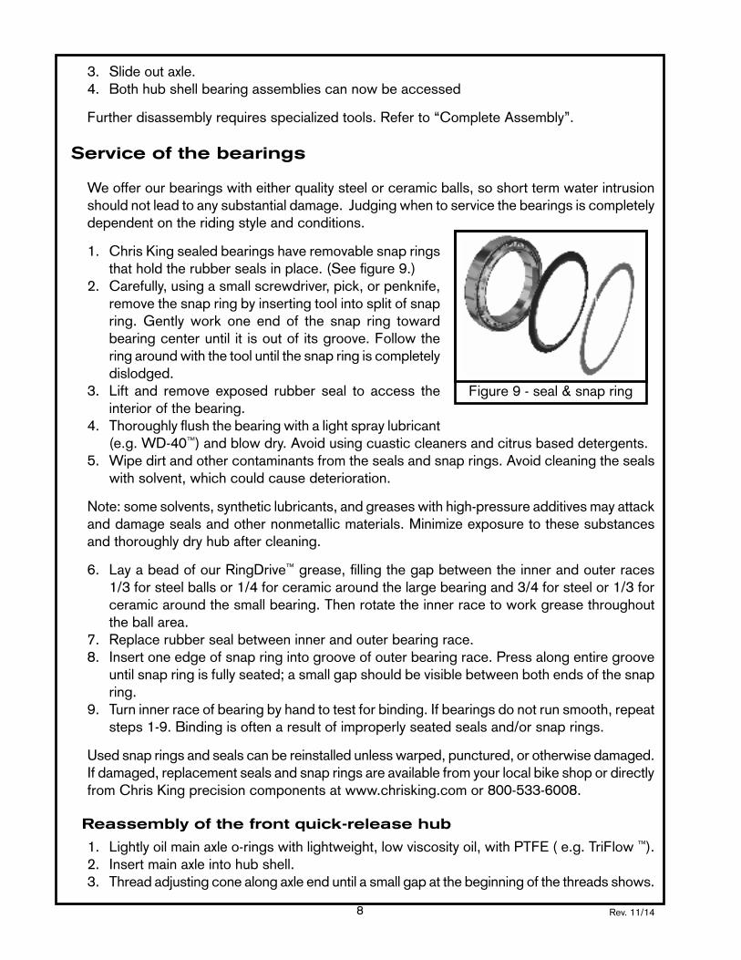
1. Chris King sealed bearings have removable snap rings that hold the rubber seals in place. (See figure 9.)
2. Carefully, using a small screwdriver, pick, or penknife, remove the snap ring by inserting tool into split of snap ring. Gently work one end of the snap ring toward bearing center until it is out of its groove. Follow the ring around with the tool until the snap ring is completely dislodged.
3. Lift and remove exposed rubber seal to access theinterior of the bearing.
4. Thoroughly flush the bearing with a light spray lubricant (e.g.WD-40™)andblowdry.Avoidusingcuasticcleanersandcitrusbaseddetergents.
5. Wipedirtandothercontaminantsfromthesealsandsnaprings.Avoidcleaningthesealswith solvent, which could cause deterioration.
Note:somesolvents,syntheticlubricants,andgreaseswithhigh-pressureadditivesmayattackanddamagesealsandothernonmetallicmaterials.Minimizeexposuretothesesubstancesand thoroughly dry hub after cleaning.
6. LayabeadofourRingDrive™ grease, filling the gap between the inner and outer races 1/3 for steel balls or 1/4 for ceramic around the large bearing and 3/4 for steel or 1/3 for ceramic around the small bearing. Then rotate the inner race to work grease throughout the ball area.
7. Replacerubbersealbetweeninnerandouterbearingrace.8. Insert one edge of snap ring into groove of outer bearing race. Press along entire groove
until snap ring is fully seated; a small gap should be visible between both ends of the snap ring.
9. Turn inner race of bearing by hand to test for binding. If bearings do not run smooth, repeat steps1-9.Bindingisoftenaresultofimproperlyseatedsealsand/orsnaprings.
Usedsnapringsandsealscanbereinstalledunlesswarped,punctured,orotherwisedamaged.If damaged, replacement seals and snap rings are available from your local bike shop or directly fromChrisKingprecisioncomponentsatwww.chrisking.comor800-533-6008.
Reassembly of the front quick-release hub
1. Lightlyoilmainaxleo-ringswithlightweight,lowviscosityoil,withPTFE(e.g.TriFlow™).2. Insertmainaxleintohubshell.3. Threadadjustingconealongaxleenduntilasmallgapatthebeginningofthethreadsshows.
Figure9-seal&snapring

Rev. 11/14 9
Grease the adjusting cone threads with waterproof grease (See figure 10 on the following page.)
4. Threadaxleendandadjustingconeontotheprotrudingthreadsofmainaxle.
5. Lightlysnugaxleendandadjustingconeuptobearing.6. Threadaxleendintoadjustingconeuntilitstops.7. Proceedto“Adjustmentofthefronttwopieceaxlehub”
(below).
Reassembly of the front bolt-on hub
1. Insertmainaxleintohubshell.2. Thread adjusting clamp onto the protruding threads of
axle.3. Snug adjusting cone up to bearing.4. Proceedto“Adjustmentof thefrontbolt-onhub”(below).
Adjustment of the front two piece axle hub
1. Insert5mmhexwrenchesintobothendsofaxleassembly.2. Holdlefthandstationaryandturnrighthandcounterclockwise1/4turnuntilassemblyis
loose.*Pro Tip: Use a bench vice to hold one of the 5mm hex wrenches.3. Holdhexwrenchesstationaryandadjustbearingpreloadwithadjustingcone.4. Advanceadjustingconeuntilitjustcontactsbearing,thenbackoffapproximately1/16turn
(thisallowsforaxlecompressionwhileunderskewerclamppressure).5. Oncepreloadisset,tightenaxleassemblyto110in.-lb.or12.43Nm6. Doublecheckadjustmentbyclampingwheelintoforkwithquick-release.Checkforplay
or binding, and readjust if needed.
Adjustment of the front one piece axle hub
1. Frontonepieceaxlehubs featureadjustingclamps whichminimizeover tighteningorover preloading of the bearings. Normal adjustment is accomplished by finger tightening adjustingringontoaxleuntilitstopsagainstbearing.Withadjustingclampfacingtowardsyou,holdoppositeendofaxlestationary,androtateclampinacounterclockwisedirectiontounscrewitfromtheaxle.Ifadjustingclampisdifficulttoposition,inserta2.5mmhexkeyinto“helperhole”onadjustingclampadjacentto2.5mmhexbolt.Usethehexkeyasa lever to preload adjusting clamp
2. Onceadjustingclampisinposition,tightenadjustingringpinchboltto10in.-lb.or1.13Nm.3. Doublecheckadjustmentbyboltingwheelintofork.Checkforplayorbinding,andreadjust
ifneeded.Adjustmentmaybeaccomplishedwhileboltedintofork.
Rear hubs
Disassembly of the rear two piece axle hub
The following instructions assume that the driveshell is facing to the right:
1. Removecogusingachainwhip,andstandardShimanoHG-stylefreewheeltool.2. Insert5mmhexwrenchesintobothendsofaxleassembly.(Seefigure11onthefollowing
page.)
Figure10-adjustingcone

Rev. 11/1410
3. Hold left hand stationarya n d t u r n r i g h t h a n d counterclockwise 1/4 turn until assembly is loose.
4. Loosen and unsc rew adjusting cone and axleend until they are free from themainaxle.
5. Removemainaxlebypullingon drive side end of main axle.
6. Hold hub orwheel in onehand and pull driveshell out with the other.
7. Bothhubshellanddriveshellbearingassembliescannowbeaccessed.
Furtherdisassemblyrequiresspecializedtools.Referto“CompleteAssembly”.
Disassembly of the rear one piece axle hub
The following instructions assume that the driveshell is facing to the right:
1. Removecogusingachainwhip,andstandardShimanoHG-stylefreewheeltool.2. Inserta2.5mmhexwrenchintoadjustingclamppinchbolt,andloosen.3. Withadjustingclampfacingtowardsyou,holdoppositeendofaxlestationary,androtate
coneinacounterclockwisedirection.Afteronecompleterevolutiontheadjustingconeshouldbefreefromtheaxle.Ifadjustingclampisdifficulttoposition,inserta2.5mmhexkeyinto“helperhole”onadjustingclampadjacentto2.5mmhexbolt.Usethehexkeyasa lever to unscrew adjusting clamp
4. Slideoutaxle.5 hold hub or wheel in one hand and pull driveshell with other. 6. Bothhubshellanddriveshellbearingassembliescannowbeaccessed.
Furtherdisassemblyrequiresspecializedtools.Referto“CompleteAssembly”.
Service of the bearings
We offer our bearings with either quality steel or ceramic balls, so short term water intrusion should not lead to any substantial damage. Judging when to service the bearings is completely dependent on the riding style and conditions.
1. Chris King sealed bearings have removable snap rings that hold the rubber seals in place.
2. Carefully, using a small screwdriver, pick, or penknife, remove the snap ring by inserting tool into split of snap ring. Gently work one end of
Figure11-disassemblemainaxle
Figure12-removesnapring
Rev. 11/14 11
the snap ring toward bearing center until it is out of its groove. Follow the ring around with the tool until the snap ring is completely dislodged. (see figure 12.)
3. Liftandremoveexposedrubbersealtoaccesstheinteriorofthebearing.4. Thoroughlyflushthebearingwithalightspraylubricant(e.g.WD-40™) and blow dry with
an air compressor. 5. Wipedirtandothercontaminantsfromthesealsandsnaprings.Avoidcleaningtheseals
with solvent, which could cause deterioration.
NOTE:Somesolvents,syntheticlubricants,andgreaseswithhigh-pressureadditivesmayattackanddamagesealsandothernonmetallicmaterials.Minimizeexposuretothesesubstancesandthoroughlydryhubaftercleaning.Avoidtheuseofcuasticandacidicdegreaserslikecitrus cleaners.
6. LayabeadofourRingDrive™ grease, filling the gap between the inner and outer races 1/3 for steel balls or 1/4 for ceramic around the large bearing and 3/4 for steel or 1/3 for ceramic around the small bearing. Then rotate the inner race to work grease throughout the ball area.
7. Replacerubbersealbetweeninnerandouterbearingrace.* When installing old seal be sure to install seal in its original orientation.
8. Insert one edge of snap ring into groove of outer bearing race. Press along entire groove until snap ring is fully seated; a small gap should be visible between both ends of the snap ring.
9. Turn inner race of bearing by hand to test for binding. If bearings do not run smooth, repeat steps1-9.Bindingisoftenaresultofimproperlyseatedsealsand/orsnaprings.
*Used snap rings and seals can be reinstalled unless warped, punctured, or otherwise damaged. If damaged, replacement seals and snap rings are available from your local bike shop or directly from Chris King precision components.
Maintenance of RingDrive™ & driveshell
Inspection
Havingremovedtheaxleanddriveshell(asinstructedabove),theRingDrive™ is accessible through the large sideof the hub shell. Visually inspect the hub’s interior. Under normalconditionsthegreaseshouldlookmoistandmayhavedarkenedslightly.Amodestfilmshouldcoat the moving parts.
Aswiththerestofthehub,theRingDrive™ is designed to operate with some water contamination. Water intrusion can usually be remedied with basic maintenance.
However,ifforeigndebrisisdetectableinthegreaseand/orthegreaselookshardordry,thenacompleteremovalandservicingoftheRingDrive™ is necessary.
Basic maintenance
1. Takeaclean,lintfreeragandwipeanyspentlubricantfrominsidethehubshell.Becarefulnot to drag any dirt or debris from outside the hub into the interior area.

Rev. 11/1412
2. Once the interior is clean in appearance, locate the helical splines of the drive ring about an inch inside the large bearing.
3. Usingasofttoothbrush,pullthebristlesacrossthehelixinanoutwarddirection.Workyour way all the way around the inner circumference to remove any small particles that may be in the spline grooves.
4. Oncecompleted,wipetheareadirectlyinfrontofthehelixtoremoveanydebris.Thismethodshouldbeusedtocleanthehelixonthedriveshellaswell.(Ifcompressedairisavailable,blowacrossthehelixesinlinewiththesplinegroovestoremoveanydebris.)
Withtheinteriorwipeddownandthehelixesbrushedclean,afreshapplicationoflubricantshouldbe applied. TheRingDrive™ is designed to work with our specially formulated low shearRingDrive™ grease. Do not substitute other brands of grease, as they may be too sticky for the helix of the RingDrive™.
5. Lubricate by reopening a gap between the driverings,andlayingabeadofRingDrive™
grease on the teeth between them (see figure 13).
6. Let the rings spring back together .7. Applyafewdropsoflightweight,lowviscosity
oil,withPTFE(e.g.TriFlow™) onto both the helical splines of the movable drive ring and the driveshell (see figure 14).
8. Before reinserting the driveshell into RingDrive™ area of the hub, the helical splines must be clean of any debris.
9. Reinsert the driveshell and complete theassembly as per the instructions below.
RingDrive™ service
In addition to the basic maintenance of the RingDrive™, a complete removal and servicing may benecessary. CompleteservicerequiresourHubService Tool Kit and, as a basic guideline, should be performed at least once a season. Check with your local Chris King dealer for complete service or you may purchase the tool kit at your dealer or directly from Chris King Precision Components.
In a pinch...
IfyouneedtodoaRingDrive™ service and don’t have theHubServiceToolKitorcan’tmakeittoadealer,this method may be used for temporary results:
1. Remove the axle and driveshell to access theinteriorRingDrive™ area.
Figure13-lubeRingDrive™ teeth
Figure14-lubehelicalsplines

Rev. 11/14 13
2. Pushthedriveringwithhelicalsplinesinwardtoopenagap,exposingthedriveteethandflushtheinteriorwithalightsolvent-basedspraylubricant(e.g.,WD-40™) until the area appearsclean.Blowoffanyremainingsolventuntilcompletelydry.
3. Ifcontamination isstill apparent, repeatflushingandblowcompletelydry.Acompleteservice of both hub shell bearings should be performed at the same time.
4. Finish by performing the basic maintenance as instructed above. 5. Afterassembly,carefullyhandtesthubforsmoothoperationofthebearingsandconsistent,
positiveengagementoftheRingDrive™. If performance is not improved to original quality, acompleteRingDrive™ removal service must be performed.
Reinstallation of the driveshell assembly
1. Check the helical splines of the driveshell for any particles or debris before proceeding; the driveshell must be clean before installing!
2. Applyseveraldropsoflightweight,lowviscosityoil,withPTFE(e.g.TriFlow™) on the helicalspline,O-ring,andtapereddiameterdirectlyadjacenttheO-ring.
3. Insertdriveshellintohubshell,slowly.AsthedriveshellenterstheRingDrive™ area, it will wanttomeshthehelicalsplinesofthedrivering.Asitbeginstomesh,aslightclockwiseturning motion of the driveshell will help pull it into the hub shell. Continue twisting as the driveshellpullsitselfintothehubshell.Atthebottomofitsinwardmovement,anaudible“click” or “pop” sound indicates that it has found home and is fully seated. (The “click” or “pop” is the spring retainer popping onto the driveshell and the driveshell hitting the bearing, indicating the driveshell is fully inserted.)
4. Insertafingerfromthenon-drivesidetounsureproperseating.5. Test engagement by spinning driveshell in both directions. If it does not engage, remove
driveshell,checkcleanlinessandre-insert.Re-test.6. Thehubisnowreadytohavetheaxleinstalled.
Reassembly of the rear two piece axle hub
The following instructions assume that the driveshell is facing to the right:
1. Lube o-r ing and axlesleeve with lightweight, low viscosity oil, with PTFE(e.g.TriFlow™)
2. Insertmain axle throughdrive shell and completely into hub. Axle shouldprotrude slightly through the non drive side bearing. (See figure 15.)
3. Grease the adjusting cone threads with waterproof grease
4. Threadadjustingconealongaxleenduntilasmallgapatthebeginningofthethreads
Figure16-adjustingconeFigure15-mainaxle

Rev. 11/1414
shows. (See figure 16.)5. Threadaxleendandadjustingconeontotheprotrudingthreadsofmainaxle.6. Lightlysnugaxleendandadjustingconeuptobearing.7. Threadaxleendintoadjustingconeuntilitstops.8.Proceedto“Adjustmentoftherearquick-releasehub”below.
NOTE: To improveperformance, the axles havebeenpreciselymatchedwith the needlebearingsinthedriveshell.Besuretocombineonlylikenumberedparts,(e.g.,#4axlewith#4 needle bearing race).
Reassembly of the rear one piece axle hub
The following instructions assume that the driveshell is facing to the right:
1.Lightlyoilallo-ringsandbearingcontactsurfaceswithlightweight,lowviscosityoil,withPTFE(e.g.TriFlow™).
2. Insert driveshell into the hub shell; turn in a clockwise motion while letting it pull itself in . Adistinctiveclicksoundwillindicatethatthedriveshellisfirmlyseated.
3. Insertmainaxle,smallendfirstintodriveshell.Continueuntilaxleisthroughthehubandlarge end is firmly seated in driveshell.
4. Threadadjustingclampontotheprotrudingthreadsofaxle.5. Snug adjusting clamp up to bearing.6. Proceedto“Adjustmentoftherearonepiecehub”(below).
Adjustment of the rear two piece axle hub
The following instructions assume that the drive shell is facing to the right:
1. Insert5mmhexwrenchesintobothendsoftheaxleassembly.*Pro Tip: Use a bench vice to hold one of the 5mm hex wrenches.
2. Holdleftsidestationaryandturnrighthandcounterclockwise1/4turnuntiltheassemblyis loose.
3. Holdhexwrenchesstationaryandadjustbearingpreloadwiththeadjustingthehubconeadjusting tool.
4. Advanceadjustingconeuntilitcontactsbearing.Therearhubtakesaslightlyhigheramountof preload than “no play”, since some settling may occur while riding.
5. Oncepreloadisset,tightenaxleassemblytogetherto110in.-lb.or12.43Nm.6. Checkadjustmentbyclampingwheelintoframewithquick-release.Ridefor5-10minutes,
checkforplayorbinding,andreadjustasnecessary.Doublecheckadjustmentafterthefirst5-10milesofriding.
NOTE:Correct adjustment of the rear hub is necessary for proper engagement of theRingDrive™.Ifthehubisrunloose,theRingDrive™ may not engage properly and could lead to permanent damage to the internal parts or hubshell.
Adjustment of the rear one piece hub
1. Rearonepiecehubsfeaturespecialadjustingclampswhichminimizeovertighteningorover preloading of the bearings. Normal adjustment is accomplished by finger tightening
Rev. 11/14 15
adjustingringontoaxleuntilitstopsagainstbearing.2. Once adjusting clamp is in position, tighten adjusting clamppinchbolt to 10in.-lb. or
1.13Nm.3. Doublecheckadjustmentbyboltingwheel into frame.Check forplayorbinding,and
readjustifneeded.Adjustmentmaybeaccomplishedwhileboltedintoframe.
CoMplete serviCe
Introduction to the tool
The hub tool is designed to accommodate complete disassembly and reassembly of the following Chris King hubs.
• ClassicandClassicHighFlange-frontandrear• UniversalDisc-frontandrear;allstyles• ISODisc-frontandrear;allstyles• BMX-frontandrear• SingleSpeedandSingleSpeedISO- frontandrear.
The tool is made up of the following parts
1. T-handle.Thisisthemainpartofthepressingdevice.Itisalongshaftwiththreadsononeend, and a bulbous end with a handlebar through it. It has a steel strike plate in the top of the bulbous end that may be struck with a mallet or ball peen hammer.
2. Extensionshaft.Onceagainathreadedshaftbutmuchshorter.Withaknurledsectionononeendandsmallthreadsontheother,itscrewsintotheendofthet-handle.
3. Cone washer. This part is a steel washer with one side shaped like a cone. It goes on the smallendoftheextensionshaftbeforeitisscrewedintothet-handle.Itsfunctionistomakesplitringsexpand(explainednext).
4. Splitrings.Thesearedoughnutshapedwithano-ringaroundtheoutside.Theyhavebeenpreciselycut inhalf toallowthemtobeexpandedtoabiggerdiameter.Thesearethepieces that get behind the bearings to force them out by their outer races. The big one is fortheRingDrive™, large bearing in the rear hubs. We have updated the large split ring to alsoservicetheLDfronthub.Only large split rings that are anodized red will work on the LD front hub. Do not attempt to service the LD front hub with the pewter anodized large split ring.Thesmalloneisforallthesmallaxlebearingsinbothfrontandrearhubs.
5. Knurled ring. This is the large round part with a threaded hole. It can be threaded onto eithertheextensionshaftortheT-handle.Itisusedtopullbearingsintotheirrespectivebores upon assembly or to capture parts as they are being tapped out.
6. Driveshellbushing.Thisisatubeshapedpartwithoneendbiggerthantheother.Itisused when installing bearings into drive shells and for removing the needle bearing from theBMXdriveshell.Thedriveshellbushingshouldalsobeusedasaguidewhensmallbearings are not installed
7. Spline driver. This is a socket shaped part with a 3/8” square hole in one end and a special spline on the other. It is used with a ratchet or torque wrench to remove or replace the seal ring in the driveshells.
8. Cog spline wrench. This is a large ring shaped part with a splined hole to match the cog

Rev. 11/1416
spline on the outside of the drive shell. It has two flats about the outer diameter so it can be located in a vice. It is used to hold the driveshell while torqueing on it.
9. 2RedanodizedLDadpaterbushings.Theseadapterswillbeinludedinwithcurrentservicetoolsandwillbeavailableasanaftermarketupgradeforexsistingtools.TheseadapterbushingswillbeusedwhenservicingLDfronthubs.Do not attempt to service the LD front hubs with out the red anodized bushings.
Function of the expanding split rings
1. Slide the large split ring onto the small endoftheextensionshaft.
2. Follow it by the cone washer, pointed endfirst,ontotheshaftnexttothesplitring.
3. Take this complete assembly and thread it into the hole in the threaded end of the T-handle.
4. Asyouscrewittogether,youwillforcethe cone washer into the split ring. The splitringwillbegintoexpand;continuescrewing until the cone has disappeared completely into the split ring. (See figure 17.) *Use the split ring in the orientation seen in figure 17. With the cone washer clamping the split ring, fullyexpanded,againsttheflangeoftheextensionshaftthetoolisreadytodrivea bearing. When driving bearings, the split ring should only be used in this fully expandedandclampedposition.
5. Release by unscrewing the extensionshaft from the T-handle. A hole isprovided in the end of the extensionshaftfora4mmhexkeyintheeventithas become too tight to turn with fingers.
Note: This tool set is designed only for working on Chris King hubs. It is not intended to be usedwithanyotherpartsoronanyotherhubs.Useotherthanthatforwhichitisintendedmay cause damage to the tool, other products, and/or bodily harm.
Front hubs
Disassembly of the front two piece axle hub
1. Insert5mmhexwrenchesintobothendsofaxleassembly.*Pro Tip: Use a bench vice to hold one of the 5mm hex wrenches.
2. Holdlefthandstationaryandturnrighthandcounterclockwise1/4turnuntilassemblyisloose.
Figure17-functionofthesplitring

Rev. 11/14 17
3. Loosenand unscrewadjustingconeandaxleenduntiltheyarefreefrommainaxle.4. Slideoutmainaxle.5. Bothhubshellbearingassembliescannowbeaccessed.
Disassembly of the front one piece axle hub
1. Inserta2.5mmhexwrenchintotheadjustingclamppinchbolt,andloosen.2. With adjustingconefacingtowardsyou,holdoppositeendofaxlestationary,androtate
coneinacounterclockwisedirection.Afteronecompleterevolutiontheadjustingconeshouldbefreefromtheaxle.Ifadjustingclampisdifficulttoloosen,inserta2.5mmhexkeyinto“helperhole”onadjustingclampadjacentto2.5mmhexbolt.Usethehexkeyasa lever to loosen adjusting clamp.
3. Slideoutaxle.4. Bothhubshellbearingassembliescannowbeaccessed
Removal of the bearings: Classic & ISO SD Hubs
1. Setup extensionshaft by placing small expandingsplit-ring,bigendfirst, on the small t h r e a d e d e n d followed by cone washer, tapered end facing split ring.
2. Whi le keeping extension shaftfromrotating,fullyexpandsmallexpandingsplit-ringbyturningtheT-handle.(Seefigure18.)
3. Pushknurledringflushwithhubshell.Thiswillpositionthesplit-ringdirectlybehindthebearing.
4. Capture bearing by threading knurled ring until it is snug against hub shell.5. Usingamalletorballpeenhammer,tapT-handletoremovebearingfromthehub shell.6. Withdraw tool and, if necessary, repeat for the other side.
Removal of the bearings: ISO LD Hubs
1. SlideoneofthesuppliedLDGuidebushingsontotheT-Handlewiththesmallersidefacingthe threaded portion, until it sits flush with the thrust collar.
2. Setup extension shaft by placing theRedLarge split-ring, on the small threaded endfollowed by cone washer, tapered end facing split ring.
3. InsertT-handlethroughonesideofhubshelluntilthreadedendshows.4.ThreadextensionshaftintoT-handlewithoutexpandingsplit-ring.5. PositiontheRedLargeSplit-Ringbehindthebearingyouwishtoremove,inverttheT-Handle
Figure18-removefronthubshellbearing

Rev. 11/1418
sothatthebearingrestsonthesplit-ring.(Tip:whenremovingbothbearingsitisbesttofirst remove the disc side bearing.)
6. ExpandtheRedLargeSplit-Ringbyturningtheknurledendoftheextensionshaftclockwise.Double check the split-rings orientation to ensure it is fully expanded andbehind thebearing.(Youmayinserta4mmhexkeyintotheextensionshafttoensurethesplitringisfullyexpanded.)
7. TakethesecondLDGuideBushingandslideitontotheextensionshaftwiththesmallerend inserting into the bearing’s inner race.
8. CapturebearingbythreadingknurledringuntilitissnugagainsttheLDGuideBushing,withthelaser-markedsidefacingawayfromthehub.
9. Invertthetoolsothatthehandleisnowfacingup,allowingthefirstLDGuidebushingtoslide into the others bearing’s inner race.
10.Usingamalletorballpeenhammer,tapT-handle’sStrikerplatetoremovebearingfromthe hub shell.
11.Withdrawtooland,ifnecessary,repeatfortheotherside,allowtheLDGuideBushingtotake the place of the bearing that was removed.
Removal of Bearings: ISO Lefty® SuperMax
*REMOVEDISC-SIDEBEARINGFIRST
1. SlideoneofthesuppliedLDGuideBushingsontotheT-Handlewiththelasersidefacingthe handle, until it sits flush with the Thrust Collar. ( See figure 19.)
2. SetupExtensionShaftbyplacingtheRedLargeSplit-Ring(withthelasermarkedsidefacingtheknurledendoftheExtensionShaft)onthesmallthreadedendfollowedbytheHubConeTool,(withthetaperedendfacingthesplitring).(Seefigure20.)
3. InserttheT-Handlethroughthenon-disc-sideofhubshellsothatthethreadedendshowson the opposite side. (See figure 21.)
4.ThreadtheextensionshaftintotheT-HandlewithoutexpandingtheSplit-Ring.(SeeFigure22.)
5. PositiontheRedLargeSplit-Ringbehindthedisc-sidebearing,inverttheT-HandlesothatthebearingrestsontheSplit-Ring.(SeeFigure23.)
6. ExpandtheRedLargeSplit-RingbyturningtheknurledendoftheExtensionShaftclockwise.DoublechecktheSplit-Ring’sorientationtoensurethatitisfullyexpandedandbehindthebearing.(Youmayinserta4mmhexkeyintotheExtensionShafttoensurethattheSplit-Ringisfullyexpanded.)(Seefigure24.)
7. Take the second LD Guide Bushing (with the laser marked side facing
LD Guide Bushing
Knurled RingLaser Side
Knurled Ring
LD Guide Bushing
Laser Side
LDGUIDEBUSHING&KNURLEDRINGORIENTATION

Rev. 11/14 19
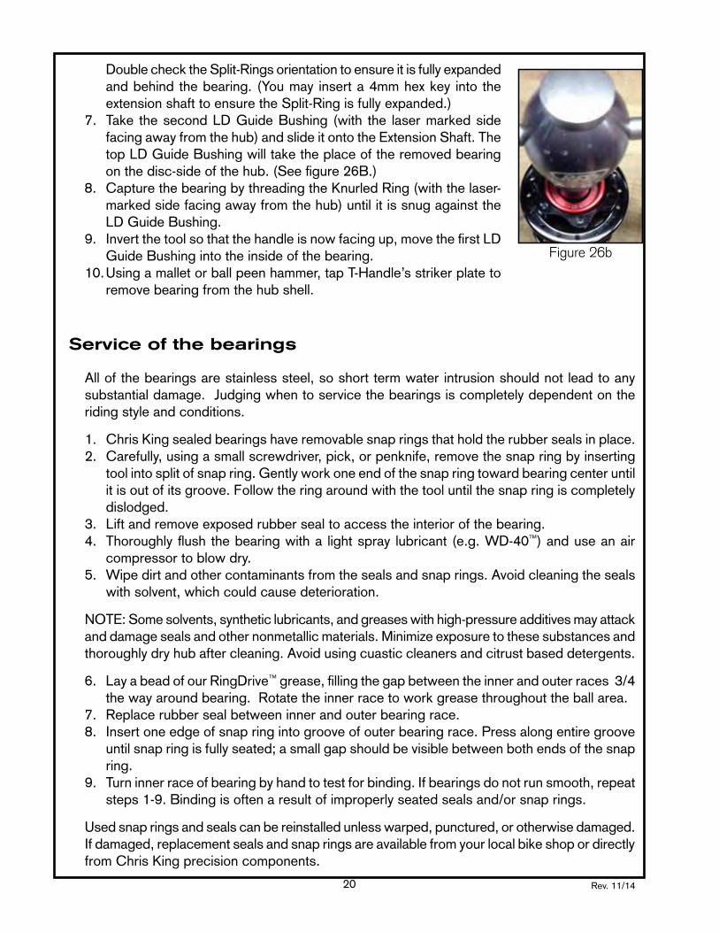
towardthehub)andslideitontotheExtensionShaft.(Seefigure25.)8. PleaseseeFigure26A&26B.CapturethebearingbythreadingtheKnurledRing(withthe
laser-markedsidefacingawayfromthehub)untilitissnugagainsttheLDGuideBushing.(See figure 26.)
9. Invertthetoolsothatthehandleisnowfacingup,movethefirstLDGuideBushingintothe inside of the bearing. (See figure 27.)
10.Usingamalletorballpeenhammer,tapT-Handle’sstrikerplatetoremovethebearingfromthe hub shell. (See figure 28.)
*NON-DISCSIDEBEARING
Usetheimagesfromthedisc-sidebearingremovalasareference.NotethechangeintheorientationoftheLDGuideBushingatstep26b.
1. SlideoneofthesuppliedLDGuideBushingsontotheT-Handlewiththelasersidefacingthe handle, until it sits flush with the thrust collar.
2. SetupextensionshaftbyplacingtheRedLargeSplit-Ring(with the lasermarkedsidefacingtheknurledendoftheExtensionShaft)onthesmallthreadedendfollowedbytheHubConeTool,(withthetaperedendfacingtheSplit-Ring).
3. InserttheT-HandlethroughtheNon-Discsideofhubshellsothatthreadedendshowsonthe opposite side.
4.ThreadtheextensionshaftintotheT-HandlewithoutexpandingtheSplit-Ring.5. PositiontheRedLargeSplit-Ringbehindthenon-disc-sidebearing,inverttheT-Handleso
thatthebearingrestsontheSplit-Ring.6. ExpandtheRedLargeSplit-RingbyturningtheknurledendoftheExtensionShaftclockwise.
Fiugure 26B Figure 27 &28
Figure 19 Figure 20 Figure 21 and 22 Figure 23 and 24
Figure 25 Figure 26A
Rev. 11/1420
DoublechecktheSplit-Ringsorientationtoensureitisfullyexpandedandbehindthebearing.(Youmay inserta4mmhexkey intotheextensionshafttoensuretheSplit-Ringisfullyexpanded.)
7. Take thesecondLDGuideBushing (with the lasermarkedsidefacingawayfromthehub)andslideitontotheExtensionShaft.ThetopLDGuideBushingwilltaketheplaceoftheremovedbearingonthedisc-sideofthehub.(Seefigure26B.)
8. CapturethebearingbythreadingtheKnurledRing(withthelaser-marked side facing away from the hub) until it is snug against the LDGuideBushing.
9. Invertthetoolsothatthehandleisnowfacingup,movethefirstLDGuideBushingintotheinsideofthebearing.
10.Usingamalletorballpeenhammer,tapT-Handle’sstrikerplatetoremove bearing from the hub shell.
Service of the bearings
Allofthebearingsarestainlesssteel,soshorttermwaterintrusionshouldnotleadtoanysubstantial damage. Judging when to service the bearings is completely dependent on the riding style and conditions.
1. Chris King sealed bearings have removable snap rings that hold the rubber seals in place.2. Carefully, using a small screwdriver, pick, or penknife, remove the snap ring by inserting
tool into split of snap ring. Gently work one end of the snap ring toward bearing center until it is out of its groove. Follow the ring around with the tool until the snap ring is completely dislodged.
3. Liftandremoveexposedrubbersealtoaccesstheinteriorofthebearing.4. Thoroughlyflushthebearingwitha lightspray lubricant (e.g.WD-40™) and use an air
compressor to blow dry. 5. Wipedirtandothercontaminantsfromthesealsandsnaprings.Avoidcleaningtheseals
with solvent, which could cause deterioration.
NOTE:Somesolvents,syntheticlubricants,andgreaseswithhigh-pressureadditivesmayattackanddamagesealsandothernonmetallicmaterials.Minimizeexposuretothesesubstancesandthoroughlydryhubaftercleaning.Avoidusingcuasticcleanersandcitrustbaseddetergents.
6. LayabeadofourRingDrive™ grease, filling the gap between the inner and outer races 3/4 thewayaroundbearing.Rotatetheinnerracetoworkgreasethroughouttheballarea.
7. Replacerubbersealbetweeninnerandouterbearingrace.8. Insert one edge of snap ring into groove of outer bearing race. Press along entire groove
until snap ring is fully seated; a small gap should be visible between both ends of the snap ring.
9. Turn inner race of bearing by hand to test for binding. If bearings do not run smooth, repeat steps1-9.Bindingisoftenaresultofimproperlyseatedsealsand/orsnaprings.
Usedsnapringsandsealscanbereinstalledunlesswarped,punctured,orotherwisedamaged.If damaged, replacement seals and snap rings are available from your local bike shop or directly from Chris King precision components.
Figure 26b

Rev. 11/14 21
Reinstallation of the bearings: Classic & ISO SD Hubs
1. Insert small inner seal into bearing bore. On ISO hubs install the disc side bearing first.
2. Place small hub bearing, black seal side first, onto bareT-handle.
3. Insert knurled ring, small end first, into opposite side of hub shell.
4. PassT-handlewith bearingthrough installation side of hub shell and thread into knurled ring. Continue turningT-handletopressbearinguntilitisfirmlyseated.(Seefigure29.)LoosenT-handle,turnknurled ring180°and tightenT-handle topressbearingagain. (Thisassures thebearing is seated flatly.)
5. Withdraw tool and, if necessary, repeat for the other side.
Reinstallation of the bearings: ISO LD Hubs
1. InsertLDHubinnersealintothehubshell’sbearingbore.2. SlideLDGuideBushingontotheT-Handleflushwiththethrustcollarwiththelargerside
against the thrust collar.3 PlacethesealedLDhubbearing,seal/snap-ringsidefacingtheLDGuidebushingonthe
T-Handle.3. InsertthesmallendoftheLDGuideBushingalongwithknurledring,withthelasermarked
side facing in, into opposite side of hub shell.4. PassT-handlewithbearingthroughinstallationsideofhubshellandthreadintoknurledring.
ContinueturningT-handletopressbearinguntilitisfirmlyseated.LoosenT-handle,turnknurledring180°andtightenT-handletopressbearingagain.(Thisassuresthebearingis seated flat)
5. Withdraw tool and, if necessary, repeat for the other side.
Reinstallation of the bearings: ISO Lefty® SuperMax Hubs
*INSTALLDISC-SIDEBEARINGFIRST
1. Insert bearing hub inner seal into the hub shell’s bearing bore. (See figure 30.)2. SlideLDGuideBushingontotheT-Handleflushwiththelasersidefacingthehandle,until
it sits flush with the Thrust Collar. (See figure 31.)3 Placethesealedhubbearing,withtheseal/snap-ringsidefacingtheLDGuideBushing
ontheT-Handle.(Seefigure32.)4. Insert thesmallendof theLDGuideBushingalongwithKnurledRing,(withthe laser
marked side facing in) into opposite side of hub shell. (See figure 33.)
Figure29-pressfronthubshellbearings

Rev. 11/1422
5. PassT-Handlewithbearingthroughdiscsideof thehubshellandthread intoKnurledRing.(MakesurethatthelasermarkedsideoftheKnurledRingfacestowardsthehub).ContinueturningT-Handletopressbearinguntilitisfirmlyseated.LoosenT-Handle,rotatetheKnurledring90°andthentightenT-Handletocontinuepressingbearing.(Thisassuresthat the bearing is seated flat) (See figure 34.)
6.RemovetheKnurledRingandtheLDGuideBushingandinsertthenon-disc-sidehubinner seal into the hubshell’s bore. (See figure 35.)
7.Setbearinginbore.*Makesurethatseal/snapringsideisfacingtheLDguidebushing.(See figures 36 and 37.)
8.InsertthesmallendoftheLDGuideBushing,makesurethatthelasermarkedsideoftheLDguidebushingfacesawayfromthehub.(Seefigure38.)
9.ThreadontheKnurledRing.*MakesurethatthelasermarkedsideoftheKnurledRing
Figure 35 Figure 37 Figure 34 Figure 36
Figure 38 Figure 39 Figure 40
Figure 30 Figure 31 Figure 32 Figure 33
Rev. 11/14 23
faces towards the hub. (See figure 39.)10.ContinueturningT-Handletopressthebearinguntilitis
firmlyseated.LoosenT-Handle,rotatetheKnurledRing90°andtightentheT-Handletopressthebearingagain.(This assures the bearing is seated flat) (See figure 40)
Reassembly of the front two piece axle hub
1. Lubricate themain axle o-ringswith lightweight, lowviscosityoil,withPTFE(e.g.TriFlow™).
2. Insertmainaxleintohubshell.OneISOandUnihubsinsertaxlefromthediscside.
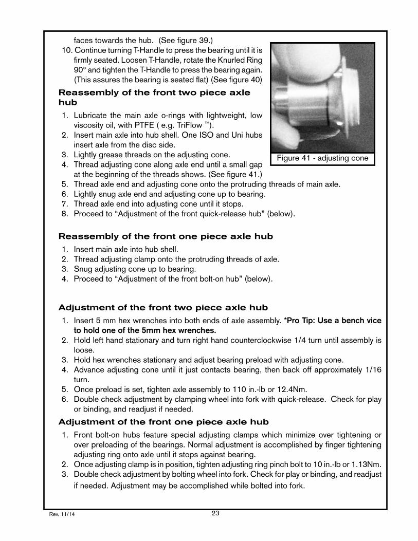
3. Lightly grease threads on the adjusting cone. 4. Threadadjustingconealongaxleenduntilasmallgap
at the beginning of the threads shows. (See figure 41.)5. Threadaxleendandadjustingconeontotheprotrudingthreadsofmainaxle.6. Lightlysnugaxleendandadjustingconeuptobearing.7. Threadaxleendintoadjustingconeuntilitstops.8. Proceedto“Adjustmentofthefrontquick-releasehub”(below).
Reassembly of the front one piece axle hub
1. Insertmainaxleintohubshell.2. Threadadjustingclampontotheprotrudingthreadsofaxle.3. Snug adjusting cone up to bearing.4. Proceedto“Adjustmentofthefrontbolt-onhub”(below).
Adjustment of the front two piece axle hub
1. Insert5mmhexwrenchesintobothendsofaxleassembly.*Pro Tip: Use a bench vice to hold one of the 5mm hex wrenches.
2. Holdlefthandstationaryandturnrighthandcounterclockwise1/4turnuntilassemblyisloose.
3. Holdhexwrenchesstationaryandadjustbearingpreloadwithadjustingcone.4. Advanceadjustingconeuntil it justcontactsbearing,thenbackoffapproximately1/16
turn.5. Oncepreloadisset,tightenaxleassemblyto110in.-lbor12.4Nm.6. Doublecheckadjustmentbyclampingwheelintoforkwithquick-release.Checkforplay
or binding, and readjust if needed.
Adjustment of the front one piece axle hub
1. Frontbolt-onhubs feature special adjustingclampswhichminimizeover tighteningorover preloading of the bearings. Normal adjustment is accomplished by finger tightening adjustingringontoaxleuntilitstopsagainstbearing.
2. Onceadjustingclampisinposition,tightenadjustingringpinchboltto10in.-lbor1.13Nm.3. Doublecheckadjustmentbyboltingwheelintofork.Checkforplayorbinding,andreadjust
ifneeded.Adjustmentmaybeaccomplishedwhileboltedintofork.
Figure41-adjustingcone

Rev. 11/1424
Rear hubs
Disassembly of the rear two piece axle hub
The following instructions assume that the drive shell is facing to the right:
1. Remove casset te permanufacturer’s instructions.
2. Insert5mmhexwrenchesinto both ends of axleassembly. (See figure 42.) *Pro Tip: Use a bench vice to hold one of the 5mm hex wrenches.
3. Hold left hand stationarya n d t u r n r i g h t h a n d counterclockwise 1/4 turn until assembly is loose.
4. Loosen and unscrew adjustingconeandaxleenduntiltheyarefreefromthemainaxle.
5. Removemainaxlebypullingondrivesideendofmainaxle.6. Holdhuborwheelinonehandandpulldriveshelloutwiththeother.7. Bothhubshellanddriveshellbearingassembliescannowbeaccessed.
Disassembly of the rear one piece axle hub
The following instructions assume that the drive shell is facing to the right:
1. Removecassettepermanufacturer’sinstructions.2. Inserta2.5mmhexwrenchintoadjustingclamppinchbolt,andloosen.3. Withadjustingclampfacingtowardsyou,holdoppositeendofaxlestationary,androtate
coneinacounterclockwisedirection.Afteronecompleterevolutiontheadjustingconeshouldbefreefromtheaxle.Ifadjustingclampisdifficulttoposition,inserta2.5mmhexkeyinto“helperhole”onadjustingclampadjacentto2.5mmhexbolt.Usethehexkeyasa lever to loosen adjusting clamp
4. Slideoutaxle.5 Holdhuborwheelinonehandandpulldriveshellwithother.6. Bothhubshellanddriveshellbearingassembliescannowbeaccessed.
Removal of the non-drive side hub bearing
1. Setupextensionshaftbyplacingsmallexpandingsplit-ring,bigendfirst,on thesmallthreaded end followed by cone washer, tapered end facing split ring.
2. InsertT-handlethroughlargesideofthehubshelluntilthreadedendshows.3. ThreadextensionshaftintoT-handlewithoutexpandingsplit-ring.4. Positionthesplit-ringdirectlybehindthebearing.Completelythreadknurledring,smallend
first,thelasermarkfacingoutward,ontotheextensionshaft,thenbackoffexactly1/2turn.5. Whilekeepingextensionshaft from rotating, fullyexpandsmall expandingsplit-ringby
turningT-handle.6. Capture bearing by advancing knurled ring until it is snug against hub shell.
Figure42-disassemblemainaxle

Rev. 11/14 25
7. Usingaballpeenhammer,tap T-handle to removebearing from hub shell. (See figure 43.)
Removal of the RingDrive™ mechanism and drive side bearing
1. Setup extension shaft byplacing large expandingsplit-r ing on the smallthreaded end followed by cone washer, tapered end facing split ring. *If the non-drive side bearing has already been removed, slide driveshell bushing tool on to T-handle with the wide side facing the thrust collar.
2. InsertT-handlethroughthenon-drive side of the hubshelluntilitextendsbeyondthe other side.
4. ThreadextensionshaftintoT-handlewithoutexpandingsplit-ring.
5. Pull assembled tool towards non-drivesideuntilknurledring is bottomed in drive side bearing.
6. Whilekeepingtheextensionshaft from rotating, rotate T-handletofullyexpandthelarge expanding split-ringbehind the spring retainer. (See figure 44.)
7. Lightly push tool towards the driveside until it stops, then thread knurled ring with the laser mark facing outward. Rotate knurledring until it again bottoms on thedrivesidebearing.(ThiswillcaptureallRingDrive™ parts and bearing on the tool as they are removed from the hub shell.) *Never attempt to remove the driveside bearing independantly of the RingDrive™ internals.
Figure45-removeRingDrive™ assembly
Figure43-removenon-drivesidebearing
Figure44-capturewholeRingDrive™ assembly

Rev. 11/1426
8. Usingamallet,tapstrikeplatetodislodgeRingDrive™ and bearing from hub shell. (See figure 45 on the previous page.)
Disassembly of the driveshell assembly
1. MakesurethattheT-Handledriveshellbushinginstalledwiththewidesidefacingthethrustcollar.
2.Removeaxlebypullingitoutfromthesealsideofthedriveshell.3. Usecogsplinewrenchtoholddriveshellinvise.4. Unscrewsealringwithsplinedriver.5. Removecaptureplateandneedlebearingcage.6. Setupextensionshaftbyplacingsmallexpandingsplit-ring,bigendfirst,on thesmall
threadedendfollowedbyconewasher,taperedendfacingsplit-ring.7. InserttheT-handlethroughdriveshellfromthehelicalsplinedend.8. ThreadextensionshaftintoT-handlewithoutexpandingsplit-ring.9. Slide driveshell up
aga inst knur led r ing to posi t ion the split-ring justbehind the bearing; thread knurled ring with the laser mark facing inward on to the opposite end of extension shaftexactly2-1/2turns.The step on the ring will center the end of the driveshell.
10.Holding extensionshaft stat ionary, screwT-handleintoextensionshafttofullyexpandsplit-ring.Thenslideitupagainstthebearingandadvanceknurled ring to hold everything snug. (See figure 46.)
11.Hold theT-Handlewhile turning the knurled ring clockwise until the internals becomedislodged. *If the press seems tight or when removing the internals from a stainless steel driveshell it may be necessary to use a ball peen hammer to apply several blows to the strike plate.
Disassembly of the XD Driveshell Assembly
1. (Figure47)YouwillneedaChrisKingHubServiceTool.Setupyourtoolasshownwithsmallsplitringandextensionshaft.
2. (Figure48)InsertT-HandlewiththeSmallSplitRinginstalledfromthenon-drivesideoftheXDDriveshellandexpandtheSmallSplitRingbehindtheDriveshellbearing.
3. (Figure49)TheSmallSplit-RingshouldrestontheDriveshellbearing,besurethattheSmallSplit-Ringisfullyexpanded.NextslidetheDriveshellBushingdowntheT-Handleshaft as a guide.
4. (Figure50)InsertthecombinedDriveshellassemblyandT-HandleintotheCogSplineWrenchmountedonthebenchvise.ThreadtheKnurledRing(lasermarkedsideout)until
Figure46-removedriveshellbearing

Rev. 11/14 27
itissnugagainsttheXDDriveshellEndCap(donotovertighten).*Do not over tighten the Cog Spline Wrench in your vise, overtightening can cause damage to the XD Driveshell Assembly.
5. (Figure51) StrikethetopoftheT-Handle(StrikePlate)withahammertoremovetheXDDriveshellinternals.
6. (Figure52)RemovetheCogSplineWrenchfromtheviseandunthreadtheKnurledRingtoreleaseallDriveshellinternals.*The inner race of the XD Driveshell bearing can at times become partially dislodged and cause the bearing to temporarily seize. If this is the case, gently tap the inner race of the bearing with a ball peen hammer until the bearings sits evenly and spins freely.
Fig 47 Fig 48 Fig 49
Fig 51Fig 50 Fig 52

Rev. 11/1428
Disassembly of the BMX driveshell assembly
1. Removeaxlefromdriveshell.2. Usecogsplinewrenchtoholddriveshell,helicalsplinesideup,invise.3. Setupextensionshaftbyplacingsmallexpandingsplit-ring,bigendfirst,onthesmall
threadedendfollowedbyconewasher,taperedendfacingsplit-ring.4. Thread knurled ring with the laser marked side facing inward completely on to the opposite
endofextensionshaft.5. InsertT-handlethroughdriveshellfromthehelicalsplinedendpasttheBMXneedlebearings.6. ThreadextensionshaftintoT-handlewithoutexpandingsplit-ring.7. Slidedriveshellupagainstknurledringtopositionthesplit-ringjustbehindthebearing;
the step on the ring will center the end of the driveshell.8. Holdingtheextensionshaftstationary,screwT-handleintoextensionshafttofullyexpand
split-ring.Thenslideitupagainstbearingandadvanceknurledringtoholdeverythingsnug.
9. Hold theT-Handlewhile turning the knurled ring clockwise until the internals becomedislodged. *If the press seems tight it may be necessary to use a ball peen hammer. to apply several blows to the strike plate.
10.Removeextensionshafttoremovetool.
Removal of BMX needle bearing
1. Slidedriveshellbushing,bigendfirst,ontoshaftofT-handle.2. Slide driveshell, needle bearing end first, onto shaft.3. Thread knurled ring, small end first, onto shaft.4. Continue threadingT-handle intoknurled ring topushneedle intocenterofdriveshell.
Afterthebearingmovesabout1/2”,itshouldbecomefreetomoveallthewaythroughthe driveshell.
Service of the bearings
We offer our bearings with either quality steel or ceramic balls, so short term water intrusion should not lead to any substantial damage. Judging when to service the bearings is completely dependent on the riding style and conditions
1. Chris King sealed bearings have removable snap rings that hold the rubber seals in place.
2. Carefully, using a small screwdriver, pick, or penknife, remove the snap ring by inserting tool into split of snap ring. Gently work one end of the snap ring toward bearing center until it is out of its groove. Follow the ring around with the tool until the snap ring is completely dislodged. (see figure 53.)
3. Liftandremoveexposedrubbersealtoaccess Figure53-removesnapring

Rev. 11/14 29
the interior of the bearing.4. Thoroughlyflushthebearingwithalightspraylubricant(e.g.WD-40™) and blow dry with
an air compressor. 5. Wipedirtandothercontaminantsfromthesealsandsnaprings.Avoidcleaningtheseals
with solvent, which could cause deterioration.
NOTE:Somesolvents,syntheticlubricants,andgreaseswithhigh-pressureadditivesmayattackanddamagesealsandothernonmetallicmaterials.Minimizeexposuretothesesubstancesandthoroughlydryhubaftercleaning.Avoidtheuseofcuasticandacidicdegreaserslikecitrus cleaners.
6. LayabeadofourRingDrive™ grease, filling the gap between the inner and outer races 1/3 for steel balls or 1/4 for ceramic around the large bearing and 3/4 for steel or 1/3 for ceramic around the small bearing. Then rotate the inner race to work grease throughout the ball area.
7. Replacerubbersealbetweeninnerandouterbearingrace.8. Insert one edge of snap ring into groove of outer bearing race. Press along entire groove
until snap ring is fully seated; a small gap should be visible between both ends of the snap ring.
9. Turn inner race of bearing by hand to test for binding. If bearings do not run smooth, repeat steps1-9.Bindingisoftenaresultofimproperlyseatedsealsand/orsnaprings.
*Used snap rings and seals can be reinstalled unless warped, punctured, or otherwise damaged. If damaged, replacement seals and snap rings are available from your local bike shop or directly from Chris King precision components.
Reinstallation of the RingDrive™ mechanism and driveside bearing
1. The non-driveside adapter bushing should be in place beforeproceedingtoinstalltheRingDrive™ and bearing.
2. Insert spring retainer in hub shell with square stepped edge facing out.(Seefigure55.)Makesurethespringretainerhasano-ringinstalled before inserting. (See figure 54.)
3. Insert drive spring. (See figure 56.)4. Insert drive ring with the teeth facing out. (See figure 57.)5. LayabeadofRingDrive™ lube onto ratchet face of drive ring.
Figure55-springretainer
Figure56-drivespring
Figure57-drivering
Figure58-drivenring
Figure54-o-ring
Rev. 11/1430
6. Insert driven ring into the hub shell with the teeth facing the drive ring. Besure to lubricatethe o-ringwith lightweight, lowviscosity oil, with PTFE ( e.g.TriFlow ™). The splines on the outside of driven ring will engage the matching splines of the hub shellasitispushedintoexposethe bore for the bearing. (See figure 58.)
7. Place the inner seal in the bearing bore on top of driven ring.
8. InsertT-handleintohubshellfromnon-drivesideuntilitisbottomedon hub shell.
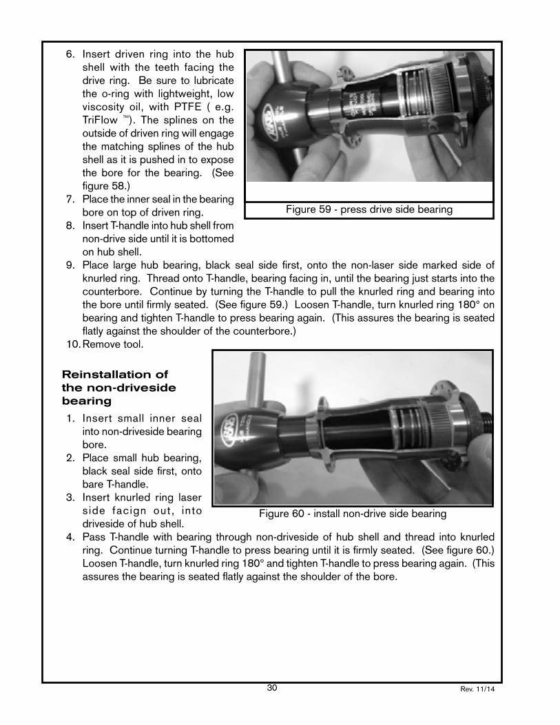
9. Place large hubbearing, black seal side first, onto the non-laser sidemarked sideofknurledring.ThreadontoT-handle,bearingfacingin,untilthebearingjuststartsintothecounterbore.ContinuebyturningtheT-handletopulltheknurledringandbearingintotheboreuntilfirmlyseated.(Seefigure59.)LoosenT-handle,turnknurledring180°onbearingandtightenT-handletopressbearingagain.(Thisassuresthebearingisseatedflatly against the shoulder of the counterbore.)
10.Removetool.
Reinstallation of the non-driveside bearing
1. Insert small inner seal intonon-drivesidebearingbore.
2. Place small hub bearing, black seal side first, onto bareT-handle.
3. Insert knurled ring laser s ide facign out, into driveside of hub shell.
4. PassT-handlewithbearing throughnon-drivesideofhubshelland thread intoknurledring.ContinueturningT-handletopressbearinguntilitisfirmlyseated.(Seefigure60.)LoosenT-handle,turnknurledring180°andtightenT-handletopressbearingagain.(Thisassures the bearing is seated flatly against the shoulder of the bore.
Figure59-pressdrivesidebearing
Figure60-installnon-drivesidebearing

Rev. 11/14 31
Reassembly of the driveshell mechanism
1. Insert small inner seal into big end of driveshell.2. Insert driveshell bearing into driveshell, tapered side out. This bearing doesn’t have a
snapringorouterseal.GreasethebearingwithRingDrive™lube.Besurethatthewhiteretainer side of the bearing sits againts the inner seal. It should slide most of the way down the bore. (See figure 61.)
3. Placedriveshellbushing,smallendfirst,ontobareT-handle.4. PassT-handlewithbushingthroughbigendofdriveshelluntilitcontactsthebearing.5. Threadknurledring,lasersideout,ontoT-handle.Advancedownuntilthesmallendof
thedriveshellnestsintotheboreintheendoftheknurledring.Becarefulnottodamagethe small end of the driveshell. (See figure 62.)
6. ContinuebyholdingtheknurledringandturningT-handletopressbearinguntilitisfirmlyseated.LoosenT-handle,turnknurledring180°ondriveshellandtightenT-handletopressbearing again. (This assures the bearing is seated flatly). If the knurled ring is too difficult to hold, the cog spline wrench may be placed on the driveshell before the knurled ring is threadedontotheT-handleinstep5.Placethecogsplinewrenchinaviceandcontinuewith step 6.
7. Removetoolsandinsertcapturesleeve,flatfaceout.8. AddalightlayerofRingDrive™ lube to the needle race and insert.9. Insert needle bearing cage.10. Insert capture plate.11.Threadsealringintodriveshell.BesuretogreasethreadswithRingDrive™ lube before
installing.12.Insertdriveshellintocogsplinewrenchandholdinvice.Usingthesplinedriver,torque
sealringto100in-lbor11.3Nm.
Figure61-driveshellseal & bearing
Figure62-pressdriveshellbearing
Figure42-needlebearing & capture plate

Rev. 11/1432
Reassembly of the XD Driveshell Assembly
1. (Figure63)DropinnersealintoXDDriveshell.*NOTE: The Inner Seal and the Capture Seal are NOT interchangable. The Inner Seal has a wider band with a smaller inner diameter than the Capture Seal.
2. (Figure 64 and Figure 65) Place bearing (greased) with the open ball side facing towards theoutsideofhubandslide theDriveshellonto theT-handle.Besure theT-Handle isequippedwithDriveshellbushingwiththelargesidefacingthebearing.ThreadKnurledRing(lasermarkedsideout)ontoT-Handleuntilthebearingisseated.
3. (Figure66)Dropinthecapturesleeve.ThecapturesleeveledgeshouldbeorientedtowardstheoutsideoftheXDDriveshell.
4. (Figure 67) Install needle bearing race. *Note the laser marked number on the needle bearing race.Besurethatthisnumberisthesamenumbermarkedonyouraxle.IfnotcontactyourChrisKingAuthorizeddealer,oronlineatwww.chrisking.comforareplacementaxleinthe
Fig 63 Fig 64 Fig 65
Fig 66 Fig 67 Fig 68

Rev. 11/14 33
correctsize.5. ApplyathinlayerofRingDriveLube™ontotheinstalledneedlebearingrace.(Notshown)6. (Figure 68) Install the needle bearing inside the needle bearing race. 7. (Figure 69) Install the capture seal. *NOTE: The Inner Seal and the Capture Seal are
NOT interchangable. The Inner Seal has a wider band with a smaller inner diameter than the Capture Seal.
8. (Figure70)PlaceXDDriveshellEndCapontopoftheDriveshellassembly.9. (Figure71)SlideassemblyontheT-HandlewiththeEndCapfacingtheThrustCollar.
ThreadKnurledRing,lasersideout,ontotheT-HandleuntiladefinitiveclickisheardandtheEndCapissecurelyinstalled.
Reassembly of the BMX driveshell mechanism
1. Insert small inner seal into big end of driveshell.2. Insert driveshell bearing into drive shell, tapered side out. It should slide most of the way
down the bore.3. Placedriveshellbushing,smallendfirst,ontobareT-handle.4. PassT-handlewithbushingthroughbigendofdriveshelluntilitcontactsthebearing.5. Threadknurledring,lasersideout,ontoT-handle.Advancedownuntilthesmallendof
thedriveshellnestsintotheendoftheknurledring.Becarefulnottodamagethesmallend of the driveshell.
6. ContinuebyturningT-handletopressbearinguntilitisfirmlyseated.LoosenT-handle,turnknurledring180°ondriveshellandtightenT-handletopressbearingagain.(Thisassures the bearing is seated flatly against the shoulder of the bore.)
7. Removedriveshellfromtool.Leavedriveshellbushinginplace,smallendonfirst.8. PlacecompleteneedlebearingontoT-handleshaftandslidedownuntil itstopsonthe
driveshell bushing.9. Placethedriveshell,lasersidein,ontotheT-handleshaft.Locatetheboreovertheneedle
bearing.10.Threadknurledring,smallendfirst,ontotheT-handle.Advancedownuntilitlocatesthe
big end of the driveshell on it’s stepped face.11.ContinuebyholdingtheknurledringandturningT-handletopressbearinguntilthedrive
Fig 69 Fig 70 Fig 71

Rev. 11/1434
shell bushing meets the driveshell. If the knurled is too difficult to hold, the cog spline wrenchmaybeplacedonthedriveshellbeforetheknurledringisthreadedontotheT-handlein step 10. Place the cog spline wrench in a vice and continue with step 11.
12.Removetools.
Reinstallation of the driveshell assembly
1. Check the helical splines of the driveshell for any particles or debris before proceeding; the driveshell must be clean before installing!
2. Applyseveraldropsoflightweight,lowviscosityoil,withPTFE(e.g.TriFlow™) on the O-ring.AddalayerofRingDrive™ lube to the helical splines.
3. Insertdriveshellintohubshell,slowly.AsthedriveshellenterstheRingDrive™ area, it will wanttomeshthehelicalsplinesofthedrivering.Asitbeginstomesh,aslightclockwiseturning motion of the driveshell will help pull it into the hub shell. Continue twisting as the driveshellpullsitselfintothehubshell.Atthebottomofitsinwardmovement,anaudible“click” or “pop” sound indicates that it has found home and is fully seated. (The “click” or “pop” is the spring retainer popping onto the driveshell and the driveshell hitting the bearing, indicating the driveshell is fully inserted. Some pushing pressure on the drive shell may be necessary to pop the spring retainer onto the end of the driveshell.)
4. Test engagement by spinning driveshell in both directions. If it does not engage, remove deiveshell,checkcleanlinessandre-insert.Re-test.
5. Thehubisnowreadytohavetheaxleinstalled.
Reassembly of the two piece rear hub
1. Insertmainaxlethroughdriveshellandcompletelyintohub.Aclickindicatesthatthemainaxleisinplace.
2. Threadadjustingconealongaxleenduntilasmallgapat the beginning of the threads shows. (See figure 72.)
3. Threadaxleendandadjustingconeontotheprotrudingthreadsofmainaxle.
4. Lightlysnugaxleendandadjustingconeuptobearing.5. Threadaxleendintoadjustingconeuntilitstops.6. Proceed to “Adjustment of rear quick-release hub”
below.
Reassembly of the rear one piece hub
1. Insertmainaxle,smallendfirst,throughdriveshellintohub.Continueuntilaxleisthroughthehubandlargeendisfirmlyseatedindriveshell.Besuretoaddoflightweight,lowviscosityoil,withPTFE(e.g.TriFlow™)totheO-ringandsleeve.
2. Threadadjustingconeontotheprotrudingthreadsofaxle.Besuretogreasetheadjustingcone threads with waterproof grease.
3. Snug adjusting cone up to bearing finger tight.4. Proceedto“Adjustmentofrearbolt-onhub”below
Adjustment of the rear two piece axle hub
The following instructions assume that the driveshell is facing to the right:
Figure72-adjustingcone
Rev. 11/14 35
1. Insert5mmhexwrenchesintobothendsoftheaxleassembly.*Pro Tip: Use a bench vice to hold one of the 5mm hex wrenches.
2. Holdleftsidestationaryandturnrighthandcounterclockwise1/4turnuntiltheassemblyis loose.
3. Holdhexwrenchesstationaryandadjustbearingpreloadwiththeadjustingthehubconeadjusting tool.
4. Advanceadjustingconeuntilitcontactsbearing.Therearhubtakesaslightlyhigheramountof preload than “no play”, since some settling may occur while riding.
5. Oncepreloadisset,tightenaxleassemblytogetherto110in.-lbor12.43Nm.6. Checkadjustmentbyclampingwheelintoframewithquick-release.Ridefor5-10minutes,
checkforplayorbinding,andreadjustasnecessary.Doublecheckadjustmentafterthefirst5-10milesofriding.
NOTE:Correct adjustment of the rear hub is necessary for proper engagement of theRingDrive™.Ifthehubisrunloose,theRingDrive™ may not engage properly and could lead to permanent damage to the internal parts or hubshell.
Adjustment of the rear one piece hub
1. Rearonepiecehubsfeaturespecialadjustingclampswhichminimizeovertighteningorover preloading of the bearings. Normal adjustment is accomplished by finger tightening adjustingringontoaxleuntilitstopsagainstbearing.
2. Onceadjustingclampisinposition,tightenadjustingclamppinchboltto10in.-lbor1.13Nm.3. Doublecheckadjustmentbyboltingwheel into frame.Check forplayorbinding,and
readjustifneeded.Adjustmentmaybeaccomplishedwhileboltedintoframe.
huB trouBle shootinG
CoMMon Questions and the likely solutions:
Complete installation, service, and maintenance instructions are available on our web site at www.chrisking.com™. We are also available to answer your technical service questions during businesshoursMondaythroughFridayat800.523.6008.
Hub will not stay adjusted.
Front and rear two piece hubs:
Whenanadjustmentismade,theaxleendmustbetorquedto110in.-lbor12.43Nmtolockthe adjusting cone’s position correctly. With less torque, the hub may seem locked, however, when clamped in, the lock may loosen slightly allowing the adjusting cone to move.
Front and rear one piece hubs:
Whenanadjustmentismade,theadjustmentclampmustbetorquedto10in.-lbor1.13Nmto lock the adjusting clamps position correctly. With less torque, the hub may seem locked, however, when clamped in, the clamp may loosen slightly allowing the adjusting clamp to move.

Rev. 11/1436
Rear:
Break-inisanormalfunctionoftherearhub.Astheangularcontactbearingssettlein,thiscausesalooseningeffectonthepreloadsetting.Expecttoadjustpreloaddirectlyafterthewheelbuildandafewmoretimesasnecessarytocompletethebreak-inperiod.Afterthatitshouldbesmoothsailingformonths...Iftheaxlelockistorquedcorrectlyandlooseningpersists, contact our technical service department for further help.
My hub creaks.
Duetotheabilityofnoisetotravelthroughoutahollowframe,hubcreaksareoftenconfusedwith bottom bracket and other creaks. Isolating the true source of the noise is essential to effective trouble shooting.
1.Thehubquickreleasemaynotbetightenoughallowingtheaxleendtomoveinthedropout.Insomecases,evenifeverythingisproperlytight,theaxlemaystillmoveslightlyintheframe.Alittleanti-seizeonthedrop-outfacesmayhelp.
Solution: Inspect and tighten the quick release.
2. Some splined cog carriers fit loosely on our driveshells. Since both are made of aluminum, theymaycreakundercertainridingconditions(e.g.,Wateranddrydust.)Additionally,ifthe lock ring is not tight enough, the cogs may move under load.
Solution:Applyathinlayerofgreaseoranti-seizetosplinesonthedriveshellandchecklockring and torque to manufacturers specifications.
3.Wehavefoundthatonsomecarriersthecogs(e.g.,XTR™ titanium,) creak at their attachment points to the spider.
Solution:Applyalightoiltotherivetsfixingthecogstothespider.
4.Thehubhasbeendesignedtoallowtheeasyremovaloftheaxleanddriveshell. Thisrequired having tapered bearing contact surfaces. These surfaces can go dry and may then make noise under heavy load.
Solution:CheckandapplyRingDrive™ lube to the driveshell on the bearing contact taper adjacenttotheo-ring(aboutthemiddleoftheoutsideofthedriveshell.)Andontheadjustingcone on the bearing contact taper.
5. The spoke tension on our wheels should be no more than 120Kgf or 1200N. In rare cases, when the wheel has been built at very high tension, the large drive side bearing can become loose and cause creaking.
Solution: Check to see if the bearing will slide out by hand. If this happens, we can supply anoversizedreplacementbearing.
The rear hub has an engagement problem.
TheRingDrive™isahighperformanceengagementsystemcapableofhighloadandextremelyrapid engagement. It relies on the fine movement of the drive ring sliding on the helical spline

Rev. 11/14 37
of thedriveshell. It is important that thisarearemaincleanandproperly lubricated. Dirt,debris, and/or drying lubricant may prevent it from functioning properly. Our hub is easy to inspectandserviceusingonly5mmand2.5mmhexwrenches.Recentimprovementshavebeenmadetominimizeabnormalsensitivitytoengagementproblems.Checkthefollowingfor possible causes of misengagement:
1.Isthehubpreloadadjustedcorrectly?Aloosehubmaycausethedriveringstonotengageproperly.
Solution: Check and properly adjust hub as necessary.
speCiFiCations
torQue speCs
headsets
NoThreadSet™
Stemcapbolt=15in.-lbor1.7Nm
GripNut™
Lockandadjustingrings=130-150in.-lbor14.7Nm-16.9Nm
2Nut™
Lockandadjustingnuts=130-150in.-lbor14.7Nm-16.9Nm
huBs
General Adjustingcones=110in.-lbor12.4NmCoglockring=20ft.-lbor27NmAdjustingclampbolt=10in.-lbor1.13NmCassetteLockring=30ft.-lbor40Nm
Universal DiscRotoradaptorscrews=28in.-lbor3.16NmAdjustingcones=110in.-lbor12.4NmFubBolts=25in.-lbor34Nm
Service tool
Driveshellsealring=100in.-lbor11.3Nm

Rev. 11/1438
NOTES

Rev. 11/14 39

Rev. 11/1440
ISO
hu
b s
pe
cifi
ca
tio
ns a
nd
wh
ee
l b
uild
ing
in
form
atio
n
HubType
AxleType
AxleWidth
(mm
)
Fla
nge
DiameterDrive
Side&non-
DriveSide
(mm
)
Cen
ter
to
FlangeDrive
Sid
e (m
m)
ISOQRSDfront
two
piec
e10
057
.431
.3
ISO15mmSDfront
one
piec
e10
057
.431
.3
ISO15mmLDfront
one
piec
e10
057
.431
.6
ISO20mmLDfront
one
piec
e11
057
.431
.6
ISO
24m
m fr
ont
one
piec
e11
057
.426
.5
ISOLefty®SuperMax
one
piec
eLe
fty
57.4
35.4
ISOLefty®LD
one
piec
eLe
fty
57.4
35.4
ISO
135
rea
ron
e pi
ece
135
57.4
20.1
ISO135x10/12mmrear
one
piec
e13
557
.420
.1
ISO142x12mmrear
one
piec
e14
257
.420
.1
ISODHG1150x10/12mmrear
one
piec
e15
057
.425
.0
ISODHG2150x10/12mm
rear
one
piec
e15
057
.428
.5
ISODHG2157x12mmrear
one
piec
e15
757
.428
.5
ISO
Sin
gle
Spe
ed r
ear
one
piec
e13
557
.432
.3
UniversalDiscfront
two
piec
e10
053
.031
.5
UniversalDiscrear
one
piec
e13
553
.021
.0
UniversalDiscSingleSpeedrear
one
piec
e13
553
.032
.0
UniversalDiscreartandem
two
piec
e14
053
.023
.5
UniversalDiscreartandem
one
piec
e14
553
.026
.0
UniversalDiscreartandem
one
piec
e16
053
.033
.7
G1:GenerationOne-Serial#beginswith1910
G2:GenerationTwo-Serial#beginswith2910
FrameAttachmentOptions
QR:Quickreleaseonly
TA:Thru-axleonly
QR/FB:QuickreleaseorFunBolts(FunBoltsonlycompatiblewithrearonepieceaxle)
Sm
all P
arts
Wei
ghts
*Add48gifhubfeaturesastainlesssteeldriveshell
**Add27gifhubfeaturesaXDDriveshell
**Add5gifusing10mmthruaxle
***
Wei
ght in
clud
es 1
8t s
tain
less
ste
el c
og (3
7g),
singl
e sp
eed
cog
spac
ers
(6g)
sin
glei
ispeedcoglockring(4g)andFunBolts(42g)
****WeightincludesCannondale®axlebolt(4g)
*****Weightincludes1mmdiscspacer(3g),Cannodale®axlebolt(4g)
Cen
ter
to F
lang
e non-DriveSide
(mm
)
FrameAttachment
Opt
ions
AvailableSpoke
HoleDrilling
Upgrade&
Con
vers
ion
Opt
ions
Wei
ght*
(g
ram
s)
Ste
el
Wei
ght*
(g
ram
s)
Cer
amic
22.2
QR
28, 3
2, 3
64
166
163
22.2
15mmTA
28, 3
2, 3
64
164
161
23.3
15mmTA
28, 3
2, 3
65
197
193
23.3
20mmTA
28, 3
2, 3
65
207
203
27.8
24m
m
28, 3
2, 3
66
240
-
26.6
Lefty
®28
, 32
-21
5***
*21
1***
*
19.6
Lefty
®28
, 32,
36
520
0***
**19
6***
**
33.9
QR/FB
28, 3
2, 3
61,
3
336
331
33.9
10/12mmTA
28, 3
2, 3
61,
3
320*
*31
5**
33.9
12mmTA
28, 3
2, 3
61,
3
325
320
38.5
10/12mmTA
32, 3
63
336*
*-
39.6
10/12mmTA
32, 3
63
338
333
39.6
12mmTA
32, 3
63
344
339
31.0
QR/FB
28, 3
2, 3
6-
411
***
406*
**
23.0
QR
32, 3
6-
150
-
34.0
QR/FB
32, 3
61,
328
2-
34.2
QR/FB
32, 3
6-
427
***
-
31.5
QR
32, 3
62,
328
4-
29.0
QR/FB
32, 3
63
366
-
33.7
QR/FB
32, 3
63
388
-
Upgrade&ConversionOptions
1:
Convertibleto135mmQR/FBaxle,135x10mmTA,135x12mmTA,142x12mmTA,and135mmtwopieceQRaxle
2:
Convertibleto130mm,135mm,and140mmaxlewidthswhenusingatwopieceaxle
3:
ConvertibletostainlesssteeldriveshellorXDdriveshell
4:
ConvertibletoQRand15mmthruaxle
5:
Convertibleto15mm,20mm,and*Lefty®axle*LeftyconversiononlyworksonLDhubswithserial#prefix1720
6:
Con
verti
ble
to 1
5mm
, 20m
m,
24m
m
WheelBuildingSpecifications
Spo
ke G
auge
:
13
, 14,
or
15 g
auge
SpokeLacingPattern:2-or-morecross
SpokeHoleDiameter:2.5mm
MaxSpokeTension:120kgf1200Nm

Rev. 11/14 41
Cla
ssic
an
d B
MX
hu
b s
pe
cifi
ca
tio
ns a
nd
wh
ee
l b
uild
ing
in
form
atio
n
HubType
AxleType
AxleWidth
(mm
)
Fla
nge
Diameter
DriveSide
Fla
nge
Diameter
Non-Drive
Sid
e
Cen
ter
to
FlangeDrive
Sid
e (m
m)
Cla
ssic
hig
h fla
nge
fron
ttw
o pi
ece
100
53.0
53.0
34.3
Cla
ssic
hig
h fla
nge
130
fron
ttw
o pi
ece
130
53.0
53.0
17.2
Cla
ssic
hig
h fla
nge
135
rea
ron
e pi
ece
135
53.0
53.0
21.0
Cla
ssic
low
flan
ge fr
ont
two
piec
e10
040
.040
.034
.0
Cla
ssic
low
flan
ge 1
30 r
ear
two
piec
e13
053
.044
.018
.5
Cla
ssic
low
flan
ge 1
35 r
ear
two
piec
e13
553
.044
.021
.0
Sin
gle
Spe
ed 1
30 r
ear
one
piec
e13
053
.053
.031
.2
Sin
gle
Spe
ed 1
35 r
ear
one
piec
e13
553
.053
.033
.7
BMXhighflangefront
one
piec
e10
053
.053
.034
.3
BMXhighflangerear
one
piec
e11
053
.053
.027
.3
BMXlowflangefront
one
piec
e10
040
.040
.034
.0
BMXlowflangerear
one
piec
e11
053
.044
.027
.0
Cla
ssic
Tan
dem
140
rea
rtw
o pi
ece
140
53.0
53.0
31.5
Cla
ssic
Tan
dem
145
rea
ron
e pi
ece
145
53.0
53.0
29.0
Cla
ssic
Tan
dem
160
rea
ron
e pi
ece
160
53.0
53.0
33.7
FrameAttachmentOptions
QR:Quickreleaseonly
QR/FB:QuickreleaseorFunBolts(FunBoltsonlycompatiblewithrearonepieceaxle)
WheelBuildingSpecifications
Spo
ke G
auge
:
13
, 14,
or
15 g
auge
SpokeLacingPattern:3-or-morecross
SpokeHoleDiameter:2.5mm
Cen
ter
to
Flangenon-
DriveSide
(mm
)
Fra
me
Attachment
Opt
ions
AvailableSpoke
HoleDrilling
Upgrade&
Con
vers
ion
Opt
ions
Wei
ght*
(gr
ams)
34.3
QR
28, 3
2, 3
6-
136
37.3
QR
28, 3
2, 3
61,
2, 3
276
33.5
QR/FB
28, 3
2, 3
61,
2, 3
302
34.0
QR
28, 3
2, 3
6-
112
38.5
QR
28, 3
2, 3
61,
2, 3
264
36.0
QR
28, 3
2, 3
61,
2, 3
266
36.2
QR/FB
28, 3
2, 3
61
370a
33.7
QR/FB
28, 3
2, 3
61
375a
34.3
BO
28, 3
2, 3
6-
216b
27.3
BO
28, 3
2, 3
6-
388c
34.0
BO
28, 3
2, 3
6-
194b
30.0
BO
28, 3
2, 3
6-
376c
23.5
QR
28, 3
2, 3
61,
2, 3
282
26.0
QR/FB
28, 3
2, 3
61,
2, 3
342d
33.7
QR/FB
28, 3
2, 3
63
352d
Upgrade&ConversionOptions
Convertibleto135mmQR/FBaxle,and135mmtwopieceQRaxle
Convertibleto130mm,135mm,and140mmaxlewidthswhenusingatwopieceaxle
Con
vert
ible
to s
tain
less
ste
el d
rives
hell
ConvertibletoQRand15mmthruaxle
Sm
all P
arts
Wei
ghts
*Add48gifhubfeaturesastainlesssteeldriveshell
**
Wei
ght i
nclu
des
18t s
tain
less
ste
el c
og (
37g)
, sin
gle
spee
d co
g sp
acer
s (6
g) s
ingl
e sp
eed
cog
lockring(4g)andFunBolts(42g)