
HR-150A manual- 0709
25
1 I. Introduction: 1. General information Hardness is an important parameter for mechanical performances of metallic and alloy materials. Generally, it refers to the capacity of a kind of material whose surface is penetrated by the other kind of harder material which has certain form and dimensions, and doesn ’t produce residual deformation by itself. Rockwell hardness test is the rapidest, easiest and most economic testing method in mechanical performance tests. Featuring high efficiency and easy-to-operate, the hardness values can be obtained directly. In most cases, it can fulfill the work that other mechanical performance test fails. Rockwell hardness tester Model HR-150A won the silver medal of the State Superior Product for three consecutive sessions. It is widely used to measure the Rockwell hardness of hard alloy, quenched and unquenched steels in the labs of research institutions, colleges, factories and mines. 2. Principle of Test Rockwell hardness test is to apply diamond cone indenter (see Fig-2) or steel ball indenter (see Fig-3) to the specimen surface in two steps as shown in Fig-1, which shall be retained for a certain period of time, and measure the residual indentation depth under preliminary test force after the main test force is removed. The Rockwell hardness is calculated by formula (1) as per the h value, the constant N and S (see Table 1). Rockwell hardness value = N -h/S …………………… (1) Table 1 Symbols and Descriptions Symbols Descriptions Units F0 Preliminary test force N F1 Main test force N F Total test force N S Unit of given scale mm N Hardness value of given scale h Residual indentation depth under preliminary test force after main test force is removed mm HRA HRC Rockwell hardness = 100 -h/0.002 HRB Rockwell hardness = 130 -h/0.002
Transcript of HR-150A manual- 0709

1
I. Introduction: 1. General information Hardness is an important parameter for mechanical performances of metallic and alloy materials. Generally, it refers to the capacity of a kind of material whose surface is penetrated by the other kind of harder material which has certain form and dimensions, and doesn’t produce residual deformation by itself. Rockwell hardness test is the rapidest, easiest and most economic testing method in mechanical performance tests. Featuring high efficiency and easy-to-operate, the hardness values can be obtained directly. In most cases, it can fulfill the work that other mechanical performance test fails. Rockwell hardness tester Model HR-150A won the silver medal of the State Superior Product for three consecutive sessions. It is widely used to measure the Rockwell hardness of hard alloy, quenched and unquenched steels in the labs of research institutions, colleges, factories and mines. 2. Principle of Test Rockwell hardness test is to apply diamond cone indenter (see Fig-2) or steel ball indenter (see Fig-3) to the specimen surface in two steps as shown in Fig-1, which shall be retained for a certain period of time, and measure the residual indentation depth under preliminary test force after the main test force is removed. The Rockwell hardness is calculated by formula (1) as per the h value, the constant N and S (see Table 1).
Rockwell hardness value = N-h/S …………………… (1) Table 1 Symbols and Descriptions
Symbols Descriptions Units F0 Preliminary test force N F1 Main test force N F Total test force N S Unit of given scale mm N Hardness value of given scale
h Residual indentation depth under preliminary test force after main test force is removed mm
HRA HRC
Rockwell hardness = 100-h/0.002
HRB Rockwell hardness = 130-h/0.002

2
Fig-1 Principle of Rockwell Hardness Test
In Fig-1: 1-----Indention depth under preliminary test force F0; 2-----Indention depth under main test force F1; 3-----Depth of elastic come-back after main test force F1 is removed; 4-----Residual indention depth h; 5-----Specimen surface 6-----measurement datum plane; 7-----position of indenter. Example: 59 HRC indicates that Rockwell hardness is 59 measured by C scale.
3. Range of Application As per hardness range and size of the specimen, different indenters and loads can be
selected and the hardness values can be indicated by different scales such as A, B and C scales for Rockwell hardness. The loads, indenters, values of the constant K and ranges of application are shown in Table 2. l Scale A is used to measure the metallic materials whose hardness exceeds 67HRC,
such as tungsten carbide, hard alloy, hard thin slabs and surface hardened parts. The range of measurement is 20—85HRA.
l Scale B is used to measure the lower-hardness parts whose range of hardness shall be 25—100 HRB, such as non-ferrous metal and its alloy, annealed steel, etc. If the hardness of specimen is smaller than 25HRB, the metal will begin to creep, the creep

3
deformation will last a long time and the result will be inaccurate. If the hardness of specimen is larger than 100HRB, error will happen since the steel ball indenter is prone to deform and the depth of indention is too small.
l Scale C is used for hardness test of specimens which are quenched or tempered, such as carbide steel, tool steel and alloyed steel. The range of measurement shall be 20—67 HRC. If the hardness of specimen is lower than 20HRC, the measurement is incorrect since it is too deep for the diamond indenter to penetrate into the specimen and the error will increase caused by the geometric shape of the indenter. If the hardness of specimen is larger than 67HRC, the diamond is easy to damage due to the large pressure produced by the sharp tip of the indenter.
Fig-2 Diamond cone indenter Fig-3 Steel ball indenter
Table 2 Usual scale for Rockwell Hardness
Test force (kg) Constant Scale Indenter (mm)
F0 F1 F N Application examples
A Diamond cone indenter 10 50 60 100 Hard metal and alloy
B Steel ball (∮1.588) indenter 10 90 100 130 Non-ferrous and soft metal
C Diamond cone indenter 10 140 150 100 Structural and tool steel
4. Technical Parameters Main technical parameters are listed in Table 3 and Fig-4.

4
Table 3 Main Technical Parameters
Items (Code) Contents Height (H) 630mm Width (W) 238mm Length (L) 466mm Max. height of specimen with protection sleeve (B) 100mm Max. height of specimen without protection sleeve (B) 170mm Distance between the center of indenter and wall of machine (A) 135mm Net weight of hardness tester 65kg
Fig-4 Schematic Diagram of Overall Dimensions Scale Range of hardness Readings allowance
20HRA<~≤75HRA ±2 HRA A
75HRA<~≤88HRA ±1.5 HRA 20HRB<~≤45HRB ±4 HRB 45HRB<~≤80HRB ±3 HRB B
80HRB<~≤100HRB ±2 HRB C 20HRC<~≤70HRC ±1.5 HRC

5
5. Descriptions of Mechanism Parts The tester is composed of machine body (1), indenter (21), loading and unloading mechanism (2, 20), measurement mechanism (23), load changeover mechanism (24), specimen support mechanism (5), buffer mechanism (19) and so on (see Fig-5).
Fig-5 Schematic diagram of parts
1. machine body 2. loading handle 3. elevation handle 4. hand wheel 5. elevating screw rod sleeve (elevating screw rod inside) 6. specimen to be tested 7. main shaft 8. smaller lever 9. larger lever 10. adjustment block 11. position mark 12. hoist ring 13. screw 14. weight changeover support bracket 15. weight 16. oil needle 17. oil carpet 18. rear cover 19. buffer 20. unloading handle 21. indenter 22. top cover 23. indication dial gauge 24. load changeover handle 25. worktable The test force applied onto the main shaft is amplified by the composition of weights and lever, i.e., indenter penetrates into the specimen surface under the guidance of buffer with the load amplified by the larger lever. At the same time when the indenter presses into the specimen, the vertical displacement produced by the main shaft is transmitted to

6
the reading device through the measurement lever and hardness value is indicated therein. l The machine body is the shell of the tester, where other parts are fitted directly or
indirectly onto the machine body. Except the worktable (25), elevating screw rod (5) and operation handle, all the other mechanisms are fitted inside the shell, convenient for cleaning.
l The total test force is composed of main test force plus preliminary test force. The preliminary test force is produced by the weight of parts including larger lever (9), and main shaft (7). The weights (15) are hanged on the larger lever through hoist ring (12), producing main test force by the lever principle.
l The top end-face of indenter (21) bears the total test force and the sharp tip penetrates into the surface of the object to be tested.
l The load changeover handle (24) can be turned to different positions, which simultaneously regulates the positions of weight changeover support bracket (14), resulting in different composition of weights which makes up three different total test forces such as 588N/60kg, 980N/100kg and 1470N/150kg.
l The loading handle (2) is to apply main test force. l The unloading handle (20) can be pushed back as per the direction shown on the
label, removing the main test force. The application of main test force can be kept at certain speed by regulating the oil needle (16) of buffer (19), avoiding any impact.
l Test value can be read directly from the indication dial gauge (23) of measurement mechanism.
l The specimen support mechanism including worktable (25), elevating screw rod (5) and hand wheel (4) is used for bearing hardness blocks and the parts to be tested.
II. Package Opening, Transportation, Installation and Commissioning: 1. Preparation l The working surroundings of the tester should be clean and dry, free of corrosive
gases. l The working surroundings of the tester should be free of foreign mechanical
vibration. l The temperature of the working surroundings should be between 10℃ to 30℃.

7
l The test table (made by the buyer) should be built up with cements or metal, having certain stiffness and strength as well as being capable to bear hardness tester and its auxiliary parts. Its surface should be fitted with a hole of ¢70mm for the elevating screw rod to pass through, as illustrated in Fig-6 (the sizes on the diagram are only for reference). The levelness of the surface should be within 0.2/1000.
l Enough space should be left around the tester for necessary installation, commissioning and maintenance.
Fig-6 Schematic Diagram of Test Table
2. Package Opening 1) Remove the packing belt B around the package box (see Fig-7). 2) Pull out the wood screws which fasten the box shell with the bottom seat by the pliers
and withdraw the box shell upwards. 3) Take out the bag of documents and sort out the operation manual (also packing list,
certificate of quality). 4) Loosen the nut on the package hook fastening the box of accessory by the spanner,
take down the package hook and box of accessory. Sort out the objects inside the box and verify whether all the parts in the packing list are available.
5) Remove the dust-proof cover. 6) Remove the four foundation bolts fastening the tester onto the bottom seat of package
box by the spanners.

8
Fig-7 Schematic diagram of package opening

9
3. Cautions for transportation l Don’t try to move the tester by oneself to prevent any damage to the tester or
personnel injury since the equipment is too heavy. Therefore the machine should be moved by at least two experienced technicians.
l During transportation, the slant of the axial line between the indenter and elevating screw rod against the vertical line should not be over 15°.
l During transportation, the contacts between the porter and the tester should be limited to Face C, D, E and F only. Don’t touch other faces and other parts of the tester so as not to influence the accuracy of the tester (see Fig-4).
l During transportation, the tester should be handled gently to avoid any collision and impact.
4. Installation and Commissioning Before installation and commissioning, the spanner, level and worktable should be standby. 1) Place the tester onto the prefabricated test table and the elevating screw rod of the
tester should be fall into the hole of the test table. 2) Remove the packing belt A on the tester (see Fig-7). 3) Take down the top cover (22), remove the screws (13) on the rear cover and then
remove the rear cover (18).
Fig-8 Removing the fastening block of larger lever

10
4) Remove the fastening bolt by the spanner, take down the fastening block and supporting block (see Fig-8).
5) Loosen the nut on the hook screw by a spanner, remove the hook screw and then pressure plate fastening the weights (see Fig-8).
6) Hold the hoist ring with hands, lift up the group of weights slowly and at the same time remove the supporting block. Place them lightly so that the cylindrical pin on the weights group just falls onto the groove on the bracket plate which brackets the weights group (see Fig-9).
Fig-9 Removing the supporting block 7) Take off the retaining rope binding the smaller lever (8), see Fig-10. 8) Turn the hand wheel (4) anticlockwise to let the elevating screw rod (5) down and
then remove the cushion block of the indenter (see Fig-11). In case that the elevating screw rod does not descend by turning the hand wheel, but to the opposite, the hand wheel rises with the elevating screw rod and the cushion block not removable, maybe the elevating screw rod and its seat (under the hand wheel) are adhered together by anti-rust oil. This can be solved by rotating the hand wheel anticlockwise to rise up to

11
20mm or so, pressing down the hand wheel by hand with force so that the elevating screw rod and its seat are disengaged.
Fig-10 Taking off the retaining rope
Fig-11 Removing the cushion block of the indenter
9) Remove the protective sleeve around the elevating screw rod, clean the elevating screw rod and hand wheel off anti-rust oil with kerosene, fill adequate amount of lubricants into the contact positions between the elevating screw rod and hand wheel, and then reassemble the protective sleeve.
12
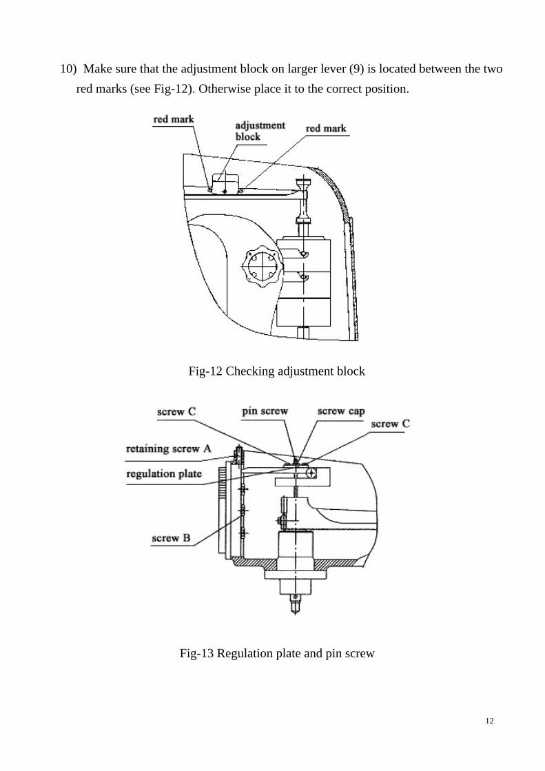
10) Make sure that the adjustment block on larger lever (9) is located between the two red marks (see Fig-12). Otherwise place it to the correct position.
Fig-12 Checking adjustment block
Fig-13 Regulation plate and pin screw

13
11) Place the larger anvil into the hole over the elevating screw rod and the level meter onto the anvil. If necessary, insert metallic cushion into the bottom seat of machine body so that the levelness in two directions are within 0.2/1000.
12) It may happen that the indication dial gauge (23) is loose during transportation. In this case, first loosen the retaining screw A on machine body, remove the indication dial gauge, tighten the three screws B at the back of the dial gauge and put the dial gauge on again (see Fig-13).
13) Turn the knurled chrome-plated shell of indication dial gauge (23) to make the “C” point right on the top. Should the larger pointer not point to “C” as shown in Fig-14, it shall be adjusted as follows: loosen the screw cap, adjust the pin screw (see Fig-13) until the larger pointer points to the “C” (see Fig-19), and then retighten the screw cap.
14) If the reading error exceeds the allowance due to transportation, regulate as follows (see Fig-13): l Make test with the higher hardness block and lower hardness block of HRC
separately. If the reading is on the high side, loosen the two screws C on the regulation plate and move the regulation plate lightly rightwards (pay attention not to move the pin screw in the middle of regulation plate), then retighten screws C. If the reading is still on the high side, repeat the above steps once again until the reading is within the range of allowance. If the reading is on the low side, move the regulation plate leftwards as per above-mentioned method.
l After calibrated with both higher hardness block and lower hardness block of HRC, in general, HRA and HRB scale will also be precise.
l While carrying out the above adjustment, the following test should not be done until the two screws C are retightened every time when the regulation plate is moved.
l The above method is only suitable for minor regulation when the reading error is within ±5 HRC or ±5 HRA.
l If slight error is found for scale B, it may be due to the steel ball. Replace the steel ball inside the steel ball indenter (see Fig-2) and try again.
15) Put on top cover (22) and rear cover (18).

14
III. Normal Operation: l Before test, the kind of scale has to be determined upon the specimen. The following
operation takes scale C as an example without specific notice, i.e. to test with diamond cone indenter and total test force up to 150kgf. It can be referred to for other scales.
1. Preparation prior to normal operation First of all, spend some time on studying the functions of every parts of the indication dial gauge, where there are hardness readings, division lines, longer pointer, shorter pointer, etc. (see Fig-14) l Black division lines are for hardness indication. The black digits at outer ring are for
hardness indication of scales A and C while red digits at inner ring are for scale B. Different scales can be composed of by changing the indenter and the weights (for detail, please refer to Table 2).
l The shorter pointer indicates the load of preliminary test force. l The longer pointer indicates the hardness value of tested specimen. The letters B and C are the symbols of scales. The position of Letter C is the zero point of division value of scale C or A. The position of Letter B is that of division value 30 for scale B.
Fig-14 Schematic diagram of Indication dial gauge

15
1) Regulate the loading ratio of main test force a. Make sure that the unloading handle (20) is at the position of unloading. Otherwise,
turn it to unloading position slowly (2 to 3 seconds or so) as per the unloading direction shown on the unloading label (see Fig-15).
Fig-15 Loading and unloading handles
b. Turn the load changeover handle (24) to the position of 150kgf and make sure that the Number 150 on the handle aligns with the red mark, as shown in Fig-16.
Fig-16 Test force selection
c. Place the standard hardness block 40~50HRC onto the worktable d. Turn the hand wheel (4) so that the hardness block raises the indenter until the shorter

16
pointer points to red mark, and then the preliminary test force has been applied. e. As per the loading direction on loading label, pull the loading handle (2) slowly
towards the front of the machine body (approximately 4 seconds) to the limit position, and then the main test force has been applied (see Fig-15).
f. Keep eyes on the longer pointer of indication dial gauge and make sure that it takes 4 to 8 seconds for it to start turning till stop. Otherwise, regulate it by turning oil needle as follows: First, loosen the bolt cap on the buffer (see Fig-17), turn the oil needle lightly. To turn it anticlockwise, the loading speed will rise, while to turn it clockwise, the loading will slow down. Repeat the above steps until everything is ok, and then tighten the bolt cap.
Fig-17 Regulating the oil needle 2) Test force selection Turn the load changeover handle until the number of selected test force points to the red mark (see Fig-16). Note: When changing the test force, the unloading handle must be at the unloading position (see Fig-15, i.e. at the limit position on the right hand). Otherwise it will cause damage to the hardness tester. 3) Install indenter (see Fig-18)
The tester is equipped with a steel ball indenter when exiting works. Following steps should be followed when reinstalling.

17
a. Put on the indenter and tighten it slightly to the extent that it will not fall down. b. Place the standard block onto the worktable. c. Turn the hand wheel to apply preliminary test force. d. Pull the loading handle leftwards to apply main test force on the indenter (see
Fig-15). e. Tighten the screw. That’s all for the installation.
Fig-18 Install the indenter
4) The specimen should meet the following requirements a. It should have certain size and thickness. The distance between two centers of
adjacent indentions and that between the center of indention and edge of specimen should be more than 3mm. The minimum thickness should be no less than 8 times to the depth of indention. After test, the binding surface of the specimen should be free of obvious hint of deformation. The minimum thickness is subject to the quality of material and the load selected. The table 4 is only a reference.
b. The surface to be tested should be flat generally. If it is a curved face and the radius of curvature is not too big, the test result should be corrected. The correction of cylindrical specimen is included in Table 5 and Table 6.
c. The surface of specimen should be polished with the finish no less than . The polishing should not influence the hardness, i.e., no hardening or tempering phenomena. The surface finish of binding face should be no less than . The surface to be tested, binding surface and worktable surface should be kept clean. The specimen shall be placed on the worktable reliably and no movement should happen.

18
d. Be sure that the test force applied should be perpendicular to the surface to be tested. To test the specimens with curved shapes or other abnormal shapes, specialized anvil should be adopted and proper position should be selected. For example, V-shaped anvil shall be used for cylindrical specimen. To test the specimens hollow inside, much attention should be paid not to produce deformation by test force, or the measured hardness value is incorrect.
Table 4 Minimum Thickness of Specimen
Scale Hardness value
(HR) Minimum thickness
(mm) Scale
Hardness value (HR)
Minimum thickness
(mm) 70 0.7 80 1.0 80 0.5 90 0.8 A 90 0.4
B 100 0.7
25 2.0 20 1.5 30 1.9 30 1.3 40 1.7 40 1.2 50 1.5 50 1.0 60 1.3 60 0.8
B
70 1.2
C
70 0.7 2. Testing procedures 1) Clean the top end of elevating screw rod and both sides of worktable, place the
worktable into the insertion hole of elevating screw rod. Proper worktable should be chosen according to the size of the parts to be tested.
2) Clean the binding surface of specimen and place it onto the worktable. Turn the hand wheel to lift up the worktable slowly to push up the indenter. No stop or reverse action is allowed from the start until the shorter pointer points to the red mark and the longer pointer point right upwards after three circles of clockwise turning. The allowance is ±5 division lines. If it is more than 5 division lines, the spot should be invalid and repeat the test by choosing other spot.

19
3) Turn the outer shell of indication dial gauge until the longer pointer aligns with the long division line between Letter C and Letter B (see Fig-19, either anticlockwise or clockwise turn is all right).
Fig-19
4) As per the loading direction on the loading label, pull the loading handle (2) towards the front of machine body slowly (around 4 seconds) up to the left-handed limit position (see Fig-15), then the main test force has been applied and the longer pointer will rotate (see Fig-20).
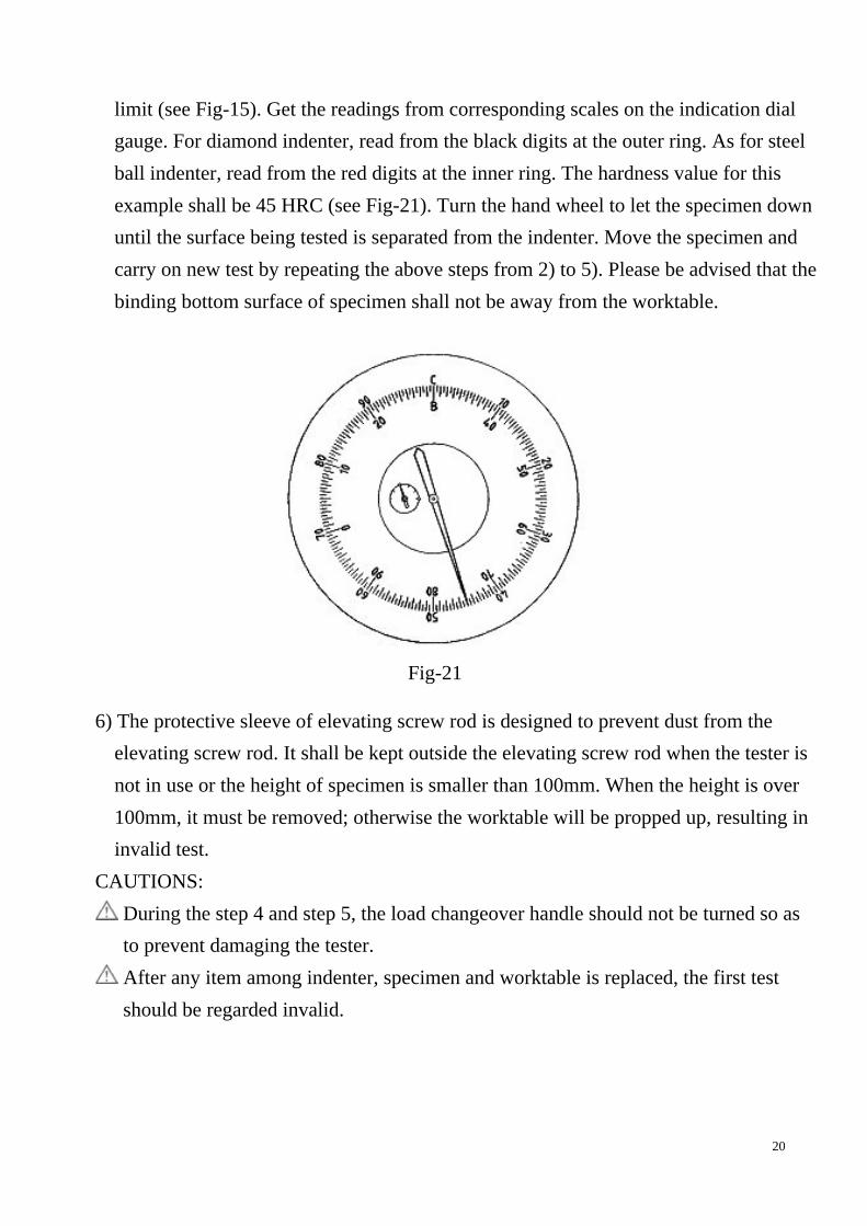
Fig-20 5) After the longer pointer stops rotating obviously, remove the main test force by
pushing slowly (2 to 3 seconds) the unloading handle clockwise to the right-handed
20
limit (see Fig-15). Get the readings from corresponding scales on the indication dial gauge. For diamond indenter, read from the black digits at the outer ring. As for steel ball indenter, read from the red digits at the inner ring. The hardness value for this example shall be 45 HRC (see Fig-21). Turn the hand wheel to let the specimen down until the surface being tested is separated from the indenter. Move the specimen and carry on new test by repeating the above steps from 2) to 5). Please be advised that the binding bottom surface of specimen shall not be away from the worktable.
Fig-21 6) The protective sleeve of elevating screw rod is designed to prevent dust from the
elevating screw rod. It shall be kept outside the elevating screw rod when the tester is not in use or the height of specimen is smaller than 100mm. When the height is over 100mm, it must be removed; otherwise the worktable will be propped up, resulting in invalid test.
CAUTIONS: During the step 4 and step 5, the load changeover handle should not be turned so as to prevent damaging the tester. After any item among indenter, specimen and worktable is replaced, the first test should be regarded invalid.

21
IV. Maintenance 1. Cleaning and Lubrication l Cover the tester with dust-proof guard when it is not in use for a long time. l Fill adequate amount of machine oil into the contact face between elevating screw
rod and hand wheel periodically. 2. Oil filling to the buffer If the pointer of indication dial gauge rotates rapidly at the beginning and then slowly later on when applying main test force, it means that the buffer is lack of machine oil. Lift up the oil carpet over the buffer and fill with clean machine oil No. 32. At the same time, pull and push the loading and unloading handles several times to let the piston move up and down so that the air inside the buffer is completely get rid of, until there is oil overflowing from the top when the piston falls down to the bottom (see Fig-22).
Fig-22 Oil filling
3. Calibration Inspect the accuracy with the standard hardness block supplied with the tester. l The tester should be calibrated regularly, usually the period can not be more than 12
months. l Clean the worktable and standard hardness block and carry out the test on the
working face of the block. It is not allowed to make a test on the binding bottom surface.
l If the reading error is too much, besides the conventional inspection listed in Table 7, check whether the binding surface of standard hardness block is burry. If yes, please

22
polish it with edge stone. l When carrying on the test on different spots on standard block, the test block should
be pulled along the worktable rather than removed away from the worktable. V. Hardness Value Correction
Since the measured value for convex specimen is lowered, the correction should be added. To the opposite, as for the concave specimen, correction should be deducted. Table 5 Corrections to scale C and A for cylindrical specimen
Diameter of cylindrical specimen (mm)
6.4 10 13 16 19 22 25 32 38 Specimen
Hardness correction
20 6.0 4.5 3.5 2.5 2.0 1.5 1.5 1.0 1.0
25 5.5 4.0 3.0 2.5 2.0 1.5 1.0 1.0 1.0
30 5.0 3.5 2.5 2.0 1.5 1.5 1.0 1.0 0.5
35 4.0 3.0 2.0 1.5 1.5 1.0 1.0 0.5 0.5
40 3.5 2.5 2.0 1.5 1.0 1.0 1.0 0.5 0.5
45 3.0 2.0 1.5 1.0 1.0 1.0 0.5 0.5 0.5
50 2.5 2.0 1.5 1.0 1.0 0.5 0.5 0.5 0.5
55 2.0 1.5 1.0 1.0 0.5 0.5 0.5 0.5 0
60 1.5 1.0 1.0 0.5 0.5 0.5 0.5 0 0
65 1.5 1.0 1.0 0.5 0.5 0.5 0.5 0 0
70 1.0 0.5 0.5 0.5 0.5 0.5 0.5 0 0
75 1.0 0.5 0.5 0.5 0.5 0.5 0 0 0
80 0.5 0.5 0.5 0.5 0 0 0 0 0
85 0.5 0.5 0.5 0 0 0 0 0 0
90 0.5 0 0 0 0 0 0 0 0
23
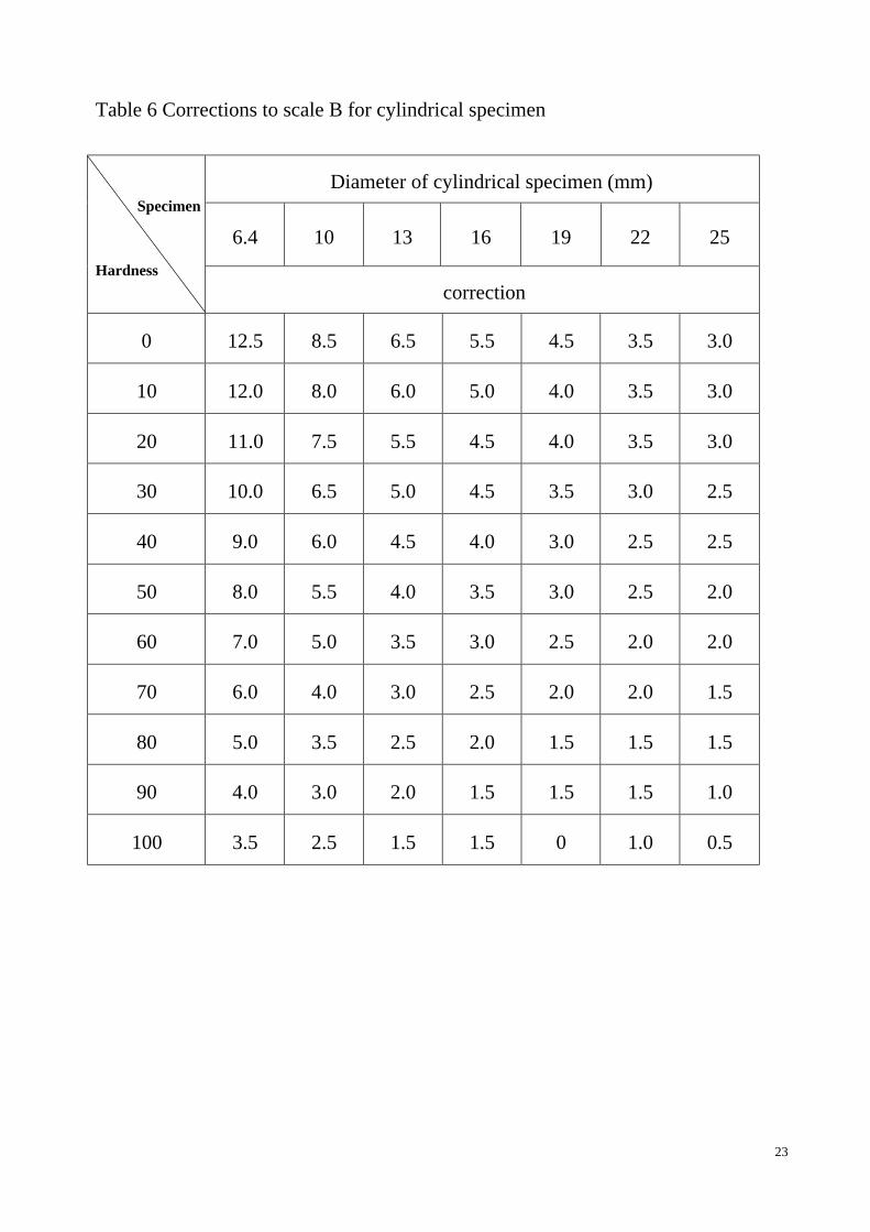
Table 6 Corrections to scale B for cylindrical specimen
Diameter of cylindrical specimen (mm)
6.4 10 13 16 19 22 25 Specimen
Hardness
correction
0 12.5 8.5 6.5 5.5 4.5 3.5 3.0
10 12.0 8.0 6.0 5.0 4.0 3.5 3.0
20 11.0 7.5 5.5 4.5 4.0 3.5 3.0
30 10.0 6.5 5.0 4.5 3.5 3.0 2.5
40 9.0 6.0 4.5 4.0 3.0 2.5 2.5
50 8.0 5.5 4.0 3.5 3.0 2.5 2.0
60 7.0 5.0 3.5 3.0 2.5 2.0 2.0
70 6.0 4.0 3.0 2.5 2.0 2.0 1.5
80 5.0 3.5 2.5 2.0 1.5 1.5 1.5
90 4.0 3.0 2.0 1.5 1.5 1.5 1.0
100 3.5 2.5 1.5 1.5 0 1.0 0.5

24
VI. Troubleshooting When the tester breaks down, the following contents can help you predict the troubles
and recommend the trouble shooting methods. If the problems remain unsolved, please contact with our after-sale service department rather than dismantle the tester by yourself.
Phenomena Reasons Remedies
Elevating screw rod is held back
Rusted or chips Get rid of the chips on elevating screw rod and hand wheel, fill with lubricants
Oil needle of buffer locked
Adjust oil needle to eliminate locking (refer to P. 16)
Main test force can not be applied
Weights not hanged properly
Adjust the position of weights as per operation manual (refer to P. 10)
Larger pointer trembles when applying main load
The levelness of worktable not right
Adjust the levelness (refer to P. 13)
Test force Check whether selected test force conforms to the requirements of the scale
Distance of indention
Check whether the distance between the centers of two adjacent indentions is too near
Check whether the indenter conforms to the requirements of the scale
Check whether the clearance between the indenter and main shaft is removed
Hardness value not precise
Indenter
Replace the indenter if damaged

25
Check whether there are impurities between worktable and elevating screw rod
Check whether selected worktable is suitable for this specimen
Worktable
Check whether protective sleeve props up worktable
Check whether the surface tested is perpendicular to the direction of test force
Check whether the rear surface is burry Specimen
Check whether the specimen is too thin
Check whether there is mechanical vibration resources around
Environment Check whether the temperature is kept at 10℃ to 30℃
Others Calibrate the hardness tester by standard block supplied