HPE ProLiant ML110 Gen10 Server User Guide · 6 UID button/LED Solid blue Activated Flashing blue...
131
HPE ProLiant ML110 Gen10 Server User Guide Part Number: 874623-003 Published: September 2018 Edition: 3 Abstract This document is for the person who installs, administers, and troubleshoots servers and storage systems. Hewlett Packard Enterprise assumes you are qualified in the servicing of computer equipment and trained in recognizing hazards in products with hazardous energy levels.
Transcript of HPE ProLiant ML110 Gen10 Server User Guide · 6 UID button/LED Solid blue Activated Flashing blue...

HPE ProLiant ML110 Gen10 Server UserGuide
Part Number: 874623-003Published: September 2018Edition: 3
AbstractThis document is for the person who installs, administers, and troubleshoots servers and storagesystems. Hewlett Packard Enterprise assumes you are qualified in the servicing of computerequipment and trained in recognizing hazards in products with hazardous energy levels.

© Copyright 2017–2018 Hewlett Packard Enterprise Development LP
NoticesThe information contained herein is subject to change without notice. The only warranties for Hewlett PackardEnterprise products and services are set forth in the express warranty statements accompanying suchproducts and services. Nothing herein should be construed as constituting an additional warranty. HewlettPackard Enterprise shall not be liable for technical or editorial errors or omissions contained herein.
Confidential computer software. Valid license from Hewlett Packard Enterprise required for possession, use,or copying. Consistent with FAR 12.211 and 12.212, Commercial Computer Software, Computer SoftwareDocumentation, and Technical Data for Commercial Items are licensed to the U.S. Government undervendor's standard commercial license.
Links to third-party websites take you outside the Hewlett Packard Enterprise website. Hewlett PackardEnterprise has no control over and is not responsible for information outside the Hewlett Packard Enterprisewebsite.
AcknowledgmentsmicroSD® is a trademark or a registered trademark of SD-3D in the United States, other countries of both.
Microsoft®, Windows®, and Windows Server® are either registered trademarks or trademarks of MicrosoftCorporation in the United States and/or other countries.
Linux® is the registered trademark of Linus Torvalds in the U.S. and other countries.
Red Hat® Enterprise Linux is a registered trademark of Red Hat, Inc. in the United States and other countries.
VMware® ESXi™ and VMware vSphere® are registered trademarks or trademarks of VMware, Inc. in theUnited States and/or other jurisdictions.

Contents
Component identification........................................................................... 7Front panel components......................................................................................................................7Front panel LEDs and buttons.............................................................................................................8
Front panel LED power fault codes.......................................................................................... 9Rear panel components...................................................................................................................... 9Rear panel LEDs and button............................................................................................................. 10
UID button functionality...........................................................................................................11System board components................................................................................................................12
System maintenance switch descriptions...............................................................................13DIMM label identification.........................................................................................................14DIMM slot locations................................................................................................................ 15
Drives................................................................................................................................................ 16Low profile LFF drive LED definitions.....................................................................................16Hot-plug drive LED definitions................................................................................................ 17Drive numbering..................................................................................................................... 18
Fans...................................................................................................................................................19Fan locations.......................................................................................................................... 20Fan mode behavior.................................................................................................................20
Setup...........................................................................................................21Optional service.................................................................................................................................21Setting up the server......................................................................................................................... 21Operational requirements..................................................................................................................24
Space and airflow requirements............................................................................................. 24Temperature requirements......................................................................................................25Power requirements................................................................................................................25Electrical grounding requirements.......................................................................................... 25
Server warnings and cautions........................................................................................................... 26Rack warnings and cautions..............................................................................................................26Electrostatic discharge...................................................................................................................... 27Setting up the server in tower mode..................................................................................................28Removing the shipping brackets....................................................................................................... 29POST screen options........................................................................................................................ 29Installing or deploying an operating system...................................................................................... 30
Operations..................................................................................................31Power up the server ......................................................................................................................... 31Power down the server .....................................................................................................................31Remove the server from the rack...................................................................................................... 31Remove the access panel................................................................................................................. 33Install the access panel..................................................................................................................... 34Remove the front bezel..................................................................................................................... 35Install the front bezel......................................................................................................................... 35Remove the PCI air baffle................................................................................................................. 36Install the PCI air baffle..................................................................................................................... 37Remove the system air baffle............................................................................................................ 38Install the system air baffle................................................................................................................ 38
3
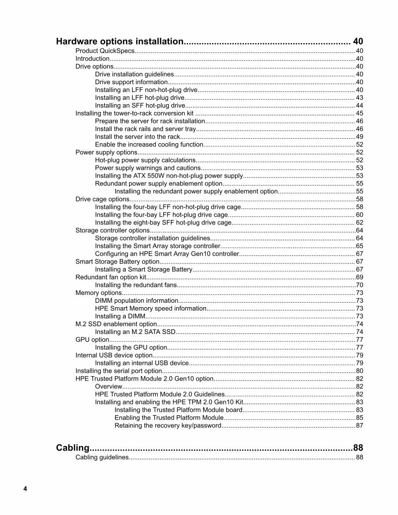
Hardware options installation.................................................................. 40Product QuickSpecs..........................................................................................................................40Introduction........................................................................................................................................40Drive options......................................................................................................................................40
Drive installation guidelines.................................................................................................... 40Drive support information........................................................................................................40Installing an LFF non-hot-plug drive....................................................................................... 40Installing an LFF hot-plug drive.............................................................................................. 43Installing an SFF hot-plug drive..............................................................................................44
Installing the tower-to-rack conversion kit ........................................................................................ 45Prepare the server for rack installation...................................................................................46Install the rack rails and server tray........................................................................................46Install the server into the rack.................................................................................................49Enable the increased cooling function....................................................................................52
Power supply options........................................................................................................................ 52Hot-plug power supply calculations........................................................................................ 52Power supply warnings and cautions..................................................................................... 53Installing the ATX 550W non-hot-plug power supply.............................................................. 53Redundant power supply enablement option......................................................................... 55
Installing the redundant power supply enablement option...........................................55Drive cage options.............................................................................................................................58
Installing the four-bay LFF non-hot-plug drive cage............................................................... 58Installing the four-bay LFF hot-plug drive cage...................................................................... 60Installing the eight-bay SFF hot-plug drive cage.................................................................... 62
Storage controller options..................................................................................................................64Storage controller installation guidelines................................................................................ 64Installing the Smart Array storage controller...........................................................................65Configuring an HPE Smart Array Gen10 controller................................................................ 67
Smart Storage Battery option............................................................................................................ 67Installing a Smart Storage Battery..........................................................................................67
Redundant fan option kit....................................................................................................................69Installing the redundant fans...................................................................................................70
Memory options.................................................................................................................................73DIMM population information..................................................................................................73HPE Smart Memory speed information.................................................................................. 73Installing a DIMM....................................................................................................................73
M.2 SSD enablement option..............................................................................................................74Installing an M.2 SATA SSD................................................................................................... 74
GPU option........................................................................................................................................77Installing the GPU option........................................................................................................77
Internal USB device option................................................................................................................79Installing an internal USB device............................................................................................79
Installing the serial port option...........................................................................................................80HPE Trusted Platform Module 2.0 Gen10 option.............................................................................. 82
Overview.................................................................................................................................82HPE Trusted Platform Module 2.0 Guidelines........................................................................ 82Installing and enabling the HPE TPM 2.0 Gen10 Kit..............................................................83
Installing the Trusted Platform Module board.............................................................. 83Enabling the Trusted Platform Module.........................................................................85Retaining the recovery key/password..........................................................................87
Cabling........................................................................................................88Cabling guidelines............................................................................................................................. 88
4

Drive cabling......................................................................................................................................89LFF non-hot-plug drive cabling...............................................................................................89LFF hot-plug drive cabling...................................................................................................... 90SFF hot-plug drive cabling......................................................................................................92
Storage controller cabling..................................................................................................................93Storage controller backup power cabling.......................................................................................... 95Smart Storage Battery cabling...........................................................................................................95Optical drive cabling.......................................................................................................................... 96M.2 SSD cabling................................................................................................................................96Front I/O cabling................................................................................................................................97Front USB 3.0 cabling....................................................................................................................... 97iLO Service Port cabling....................................................................................................................98Fan cabling........................................................................................................................................98Serial port cabling............................................................................................................................100Power supply cabling.......................................................................................................................101
Software and configuration utilities.......................................................103Server mode....................................................................................................................................103Product QuickSpecs........................................................................................................................103Active Health System Viewer.......................................................................................................... 103
Active Health System............................................................................................................103Active Health System data collection.........................................................................104Active Health System Log..........................................................................................104
HPE iLO 5........................................................................................................................................104iLO Federation......................................................................................................................105iLO Service Port....................................................................................................................105iLO RESTful API...................................................................................................................106RESTful Interface Tool..........................................................................................................106iLO Amplifier Pack................................................................................................................ 106
Integrated Management Log........................................................................................................... 106Intelligent Provisioning.....................................................................................................................107
Intelligent Provisioning operation..........................................................................................107Management Security......................................................................................................................108Scripting Toolkit for Windows and Linux..........................................................................................108UEFI System Utilities.......................................................................................................................108
Selecting the boot mode ......................................................................................................109Secure Boot..........................................................................................................................109Launching the Embedded UEFI Shell ..................................................................................110
HPE Smart Storage Administrator................................................................................................... 110USB support.....................................................................................................................................111
External USB functionality.....................................................................................................111Redundant ROM support................................................................................................................. 111
Safety and security benefits.................................................................................................. 111Keeping the system current............................................................................................................. 111
Updating firmware or system ROM....................................................................................... 111Service Pack for ProLiant...........................................................................................112Updating firmware from the System Utilities ............................................................. 113Updating the firmware from the UEFI Embedded Shell ............................................ 114Online Flash components.......................................................................................... 114
Drivers...................................................................................................................................114Software and firmware.......................................................................................................... 114Operating system version support........................................................................................ 115HPE Pointnext Portfolio........................................................................................................ 115Proactive notifications........................................................................................................... 115
5
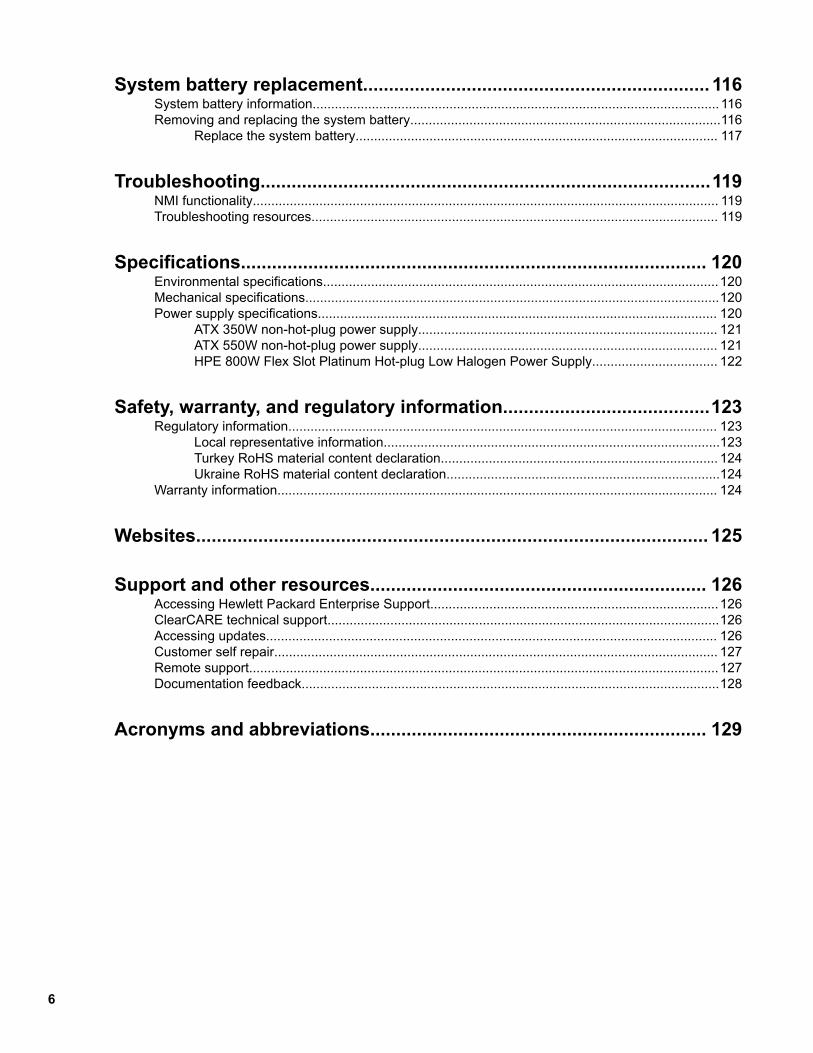
System battery replacement................................................................... 116System battery information.............................................................................................................. 116Removing and replacing the system battery....................................................................................116
Replace the system battery.................................................................................................. 117
Troubleshooting.......................................................................................119NMI functionality.............................................................................................................................. 119Troubleshooting resources.............................................................................................................. 119
Specifications.......................................................................................... 120Environmental specifications...........................................................................................................120Mechanical specifications................................................................................................................120Power supply specifications............................................................................................................ 120
ATX 350W non-hot-plug power supply................................................................................. 121ATX 550W non-hot-plug power supply................................................................................. 121HPE 800W Flex Slot Platinum Hot-plug Low Halogen Power Supply.................................. 122
Safety, warranty, and regulatory information........................................123Regulatory information.................................................................................................................... 123
Local representative information...........................................................................................123Turkey RoHS material content declaration........................................................................... 124Ukraine RoHS material content declaration..........................................................................124
Warranty information....................................................................................................................... 124
Websites................................................................................................... 125
Support and other resources................................................................. 126Accessing Hewlett Packard Enterprise Support..............................................................................126ClearCARE technical support..........................................................................................................126Accessing updates.......................................................................................................................... 126Customer self repair........................................................................................................................ 127Remote support...............................................................................................................................127Documentation feedback.................................................................................................................128
Acronyms and abbreviations................................................................. 129
6

Component identificationFront panel components
Item Description
1 Box 2
2 Box 1
3 USB 3.0 ports
4 iLO Service Port
5 PCI fan
6 Slim optical drive (optional)
Component identification 7

Front panel LEDs and buttons
Item Description Status Definition
1 Power On/Standby buttonand system power LED1
Solid green Normal
Flashing green Performing power-on sequence
Solid amber System in standby
Off No power present2
2 Health LED1 Solid green Normal
Flashing green iLO is rebooting.
Flashing amber System degraded3
Flashing red System critical3
3 NIC status LED1 Solid green Linked to network
Flashing green Network active
Off No network activity
1 When all three LEDs described in this table simultaneously, a power fault has occurred. For more information, see Frontpanel LED power fault codes on page 9.
2 Facility power is not present, power cord is not attached, no power supplies are installed, power supply failure hasoccurred, or the front I/O cable is disconnected.
3 If the health LED indicates a degraded or critical state, review the system IML or use iLO to review the system healthstatus.
8 Component identification

Front panel LED power fault codesThe following table provides a list of power fault codes, and the subsystems that are affected. Not all powerfaults are used by all servers.
Subsystem LED behavior
System board 1 flash
Processor 2 flashes
Memory 3 flashes
Riser board PCIe slots 4 flashes
FlexibleLOM 5 flashes
Removable HPE Smart Array SR Gen10 controller 6 flashes
System board PCIe slots 7 flashes
Power backplane or storage backplane 8 flashes
Power supply 9 flashes
Rear panel components
Item Description
1 Standard power supply (non-hot-plug)
2 Kensington security slot
3 Padlock eye
4 Flexible Slot power supply 1 (hot-plug)
5 Flexible Slot power supply bay 2 (hot-plug)
6 NIC port 11
7 System fan
Table Continued
Component identification 9

Item Description
8 iLO Management Port
9 Slot 5 PCIe3 x8 (8, 4, 1)
10 Slot 4 PCIe3 x16 (16, 8, 4, 1)
11 Serial port (optional)
12 Slot 3 PCIe3 x8 (8, 4, 1)
13 Slot 2 PCIe3 x8 (4, 1)
14 Slot 1 PCIe3 x16 (16, 8, 4, 1)
15 USB 3.0 port
16 USB 2.0 port
17 NIC port 21
18 Video port
1 The Broadcom 5720-based embedded HPE 332i Ethernet LAN controller provides a PCIe 2.0 x1 host interface to theonboard NIC ports.
Rear panel LEDs and button
10 Component identification

Item Description Status Definition
1 Power supply LED Solid green Normal
Off One or more of following conditions exists:
• Power is unavailable.
• Power supply failed
• Power supply is in standby mode.
• Power supply error
2 iLO link LED Solid green Network link
Off No network link
3 iLO status LED Solid green Linked to network
Flashing green Network active
Off No network link
4 NIC link LED Solid green Network link
Off No network link
5 NIC status LED Solid green Linked to network
Flashing green Network active
Off No network link
6 UID button/LED Solid blue Activated
Flashing blue System is being managed remotely.
Off Deactivated
UID button functionalityThe UID button can be used to display the Server Health Summary when the server will not power on. Formore information, see the iLO user guide on the Hewlett Packard Enterprise website (http://www.hpe.com/support/ilo-docs).
Component identification 11

System board components
Item Description
1 Fan connector 4 for the redundant system fan
2 Fan connector 3 for the default and redundant system fans
3 DIMM slots
4 24-pin power supply connector
5 RPSU connector
6 Processor
7 System battery
8 Front I/O cable connector
9 x4 SATA port 1
10 x4 SATA port 2
11 iLO Service Port
12 Front USB 3.0 connector
Table Continued
12 Component identification

Item Description
13 x1 SATA port 9
14 TPM connector
15 Fan connector 1 for the default and redundant PCI fans
16 Fan connector 2 for the redundant PCI fan
17 x1 SATA port 10
18 Storage controller backup power connectors
19 microSD slot1
20 System maintenance switch
21 Smart Storage Battery connector
22 Internal USB 2.0 connector
23 Slot 5 PCIe3 x8 (4, 1)
24 Serial port connector
25 Slot 4 PCIe3 x16 (16, 8, 4, 1)
26 Internal USB 3.0 connector
27 Slot 3 PCIe3 x8 (8, 4, 1)
28 Slot 2 PCIe3 x8 (4, 1)
29 Slot 1 PCIe3 x16 (16, 8, 4, 1)
1 If the memory card connected to the microSD slot is not visible in Windows Device Manager, in the menu bar, click View >Show hidden device.
System maintenance switch descriptionsPosition Default Function
S1 1 Off Off = iLO 5 security is enabled.
On = iLO 5 security is disabled.
S2 — Reserved
S3 Off Reserved
S4 Off Reserved
Table Continued
Component identification 13

Position Default Function
S51 Off Off = Power-on password isenabled.
On = Power-on password isdisabled.
S61, 2 Off Off = No function
On = Restore defaultmanufacturing settings
S7 — Reserved
S8 — Reserved
S9 — Reserved
S10 — Reserved
S11 — Reserved
S12 — Reserved
1You can access the redundant ROM by setting S1, S5, and S6 to On.2When the system maintenance switch position 6 is set to the On position, the system is prepared to restoreall configuration settings to their manufacturing defaults.
When the system maintenance switch position 6 is set to the On position and Secure Boot is enabled, someconfigurations cannot be restored. For more information, see Secure Boot configuration.
DIMM label identificationTo determine DIMM characteristics, see the label attached to the DIMM. The information in this section helpsyou to use the label to locate specific information about the DIMM.
14 Component identification

Item Description Example
1 Capacity 8 GB
16 GB
32 GB
64 GB
128 GB
2 Rank 1R = Single rank
2R = Dual rank
4R = Quad rank
8R = Octal rank
3 Data width on DRAM x4 = 4-bit
x8 = 8-bit
x16 = 16-bit
4 Memory generation PC4 = DDR4
5 Maximum memory speed 2133 MT/s
2400 MT/s
2666 MT/s
6 CAS latency P = CAS 15-15-15
T = CAS 17-17-17
U = CAS 20-18-18
V = CAS 19-19-19 (for RDIMM, LRDIMM)
V = CAS 22-19-19 (for 3DS TSV LRDIMM)
7 DIMM type R = RDIMM (registered)
L = LRDIMM (load reduced)
E = Unbuffered ECC (UDIMM)
For more information about product features, specifications, options, configurations, and compatibility, see theproduct QuickSpecs on the Hewlett Packard Enterprise website (http://www.hpe.com/info/qs).
DIMM slot locationsThe DIMM slots are numbered 1 through 6. The arrow in the following illustration points to the front of theserver.
Component identification 15

Drives
Low profile LFF drive LED definitions
Item LED Status Definition
1 Fault\Locate
Solid amber The drive has failed.
Solid blue The drive is operating normally and being identified by amanagement application.
Flashing amber/blue
(1 flash per second)The drive has failed, or a predictive failure alert has beenreceived for this drive; it also has been identified by amanagement application.
Flashing amber
(1 flash per second)A predictive failure alert has been received for this drive.Replace the drive as soon as possible.
2 Online\Activity
Solid green The drive is online and has no activity.
Flashing green
(4 flashes per second)The drive is operating normally and has activity.
Table Continued
16 Component identification

Item LED Status DefinitionFlashing green
(1 flash per second)
The drive is doing one of the following:• Rebuilding
• Performing a RAID migration
• Performing a strip size migration
• Performing a capacity expansion
• Performing a logical drive extension
• Erasing
• Spare part activation
Off The drive is not configured by a RAID controller or a sparedrive.
Hot-plug drive LED definitions
Item LED Status Definition
1 Locate Solid blue The drive is being identified by a host application.
Flashing blue The drive carrier firmware is being updated or requires an update.
2 Activityring
Rotating green Drive activity
Off No drive activity
3 Do notremove
Solid white Do not remove the drive. Removing the drive causes one or more ofthe logical drives to fail.
Off Removing the drive does not cause a logical drive to fail.
4 Drivestatus
Solid green The drive is a member of one or more logical drives.
Table Continued
Component identification 17

Item LED Status Definition
Flashing green The drive is doing one of the following:• Rebuilding
• Performing a RAID migration
• Performing a strip size migration
• Performing a capacity expansion
• Performing a logical drive extension
• Erasing
• Spare part activation
Flashing amber/green
The drive is a member of one or more logical drives and predicts thedrive will fail.
Flashing amber The drive is not configured and predicts the drive will fail.
Solid amber The drive has failed.
Off The drive is not configured by a RAID controller or a spare drive.
Drive numberingThe following images show the drive numbering for each of the supported drive configurations.
• Four-bay LFF non-hot-plug drive model
• Four-bay LFF hot-plug drive model
18 Component identification

• Eight-bay SFF hot-plug drive model
Fans
Component identification 19

Fan locations
Item Description
1 Default system fan
2 Default PCI fan
The server also supports the Redundant fan option kit on page 69.
Fan mode behavior• In nonredundant fan mode, a fan failure or a missing fan causes:
◦ The system Health LED to flash amber.
◦ The operating system to orderly shutdown.
• In redundant fan mode:
◦ A fan rotor failure will switch the system to nonredundant fan mode.
This change is indicated by the Health LED flashing amber. The system continues to operate normallyin this mode.
◦ A second fan rotor failure or a missing fan causes the operating system to orderly shutdown.
20 Component identification
SetupOptional service
Delivered by experienced, certified engineers, Hewlett Packard Enterprise support services help you keepyour servers up and running with support packages tailored specifically for HPE ProLiant systems. HewlettPackard Enterprise support services let you integrate both hardware and software support into a singlepackage. A number of service level options are available to meet your business and IT needs.
Hewlett Packard Enterprise support services offer upgraded service levels to expand the standard productwarranty with easy-to-buy, easy-to-use support packages that will help you make the most of your serverinvestments. Some of the Hewlett Packard Enterprise support services for hardware, software or both are:
• Foundation Care – Keep systems running.◦ 6-Hour Call-to-Repair1
◦ 4-Hour 24x7
◦ Next Business Day
• Proactive Care – Help prevent service incidents and get you to technical experts when there is one.◦ 6-Hour Call-to-Repair1
◦ 4-Hour 24x7
◦ Next Business Day
• Deployment service for both hardware and software
• Hewlett Packard Enterprise Education Services – Help train your IT staff.
1The time commitment for this repair service might vary depending on the site's geographical region. Formore service information available in your site, contact your local Hewlett Packard Enterprise supportcenter.
For more information on Hewlett Packard Enterprise support services, see the Hewlett Packard Enterprisewebsite.
Setting up the serverPrerequisitesBefore setting up the server:
• Download the latest SPP:
http://www.hpe.com/servers/spp/download
Support validation required
• Verify that your OS or virtualization software is supported:
http://www.hpe.com/info/ossupport
• Read the operational requirements for the server:
Operational requirements on page 24
• Read the safety and compliance information on the HPE website:
http://www.hpe.com/support/safety-compliance-enterpriseproducts
Setup 21

• Obtain the storage driver if needed:◦ Download it from the HPE Support Center website:
http://www.hpe.com/support/hpesc
◦ Extract it from the SPP.
• If the tower-to-rack conversion kit is used, read the rack warnings and cautions:
Rack warnings and cautions on page 26
Procedure
Unbox the server
1. Unbox the server and verify the contents:
• Server
• Power cord
• Rack-mounting hardware (optional)
• Documentation
Install the hardware options
2. (Optional) Install hardware options. For installation instructions, see Hardware options installation onpage 40.
Orient the server and connect the peripherals
3. Select the server orientation:
• Tower orientation
• Rack orientation
◦ If the server was shipped with the tower-to-rack conversion kit, install this hardware option.
◦ If the server was shipped in a rack, remove the shipping brackets.
4. Decide how to manage the server:
• Locally: Use a KVM switch or a connect a keyboard, monitor, and mouse.
• Remotely: Connect to the iLO web interface and run a remote console:
a. Verify the following:◦ iLO is licensed to use the remote console feature.
If iLO is not licensed, visit http://www.hpe.com/info/ilo.
◦ The iLO Management Port is connected to a secure network.
b. Using a browser, navigate to the iLO web interface, and then log in.
https://<iLO hostname or IP address>Note the following:
22 Setup

◦ The iLO hostname is located on the serial number/iLO information label located on the top of thechassis.
◦ If a DHCP server assigns the IP address, the IP address appears on the boot screen.
◦ If a static IP address is assigned, use that IP address.
◦ The default login credentials are located on the serial number/iLO information label located onthe top of the chassis.
c. In the side navigation, click the Remote Console & Media link, and then launch a remote console.
Power on the server
5. Press the Power On/Standby button.For remote management, use the iLO virtual power button.
Update the firmware
6. Using the SPP, update the following:
• System ROM
• Storage controller
• Network adapters
• Intelligent Provisioning
Set up the storage
7. Set up the storage. Do one of the following:
• To configure the server to boot from a SAN, see the following guide in the HPE website (https://www.hpe.com/info/boot-from-san-config-guide):
HPE Boot from SAN Configuration Guide
• If an HPE Smart Array SR controller is installed, use HPE Smart Storage Administrator to createarrays:
a. From the boot screen, press F10 to run Intelligent Provisioning.
b. From Intelligent Provisioning, run HPE Smart Storage Administrator.
• If no controller option is installed, do one of the following:◦ AHCI is enabled by default. Deploy an OS or virtualization software.
◦ Disable AHCI, enable software RAID, and then create an array:
a. From the boot screen, press F9 to run UEFI System Utilities.
b. From the UEFI System Utilities screen, select System Configurations > BIOS/PlatformConfiguration (RBSU) > Storage Options > SATA Controller Options > Embedded SATAConfiguration > Smart Array SW RAID Support.
c. Enable Smart Array SW RAID Support.
Setup 23

d. Save the configuration and reboot the server.
e. Create an array:
I. From the boot screen, press F9 to run UEFI System Utilities.
II. From the UEFI System Utilities screen, select System Configuration > EmbeddedStorage: HPE Smart Storage S100i SR Gen10 > Array Configuration > Create Array.
Deploy an OS or virtualization software
8. Deploy an OS or virtualization software. Do one of the following:
• From the boot screen, press F10 to run Intelligent Provisioning and deploy an OS.
• Manually deploy an OS:
a. Insert the installation media.
For remote management, click Virtual Drives in the iLO remote console to mount images, driver, orfiles to a virtual folder. If a storage driver is required to install the OS, use the virtual folder to storethe driver.
b. From the boot screen, press F11 to select the boot device.
c. After the OS is installed, update the drivers.
Register the server
9. To experience quicker service and more efficient support, register the server at the HPE website:https://myenterpriselicense.hpe.com
Operational requirements
Space and airflow requirementsTo allow for servicing and adequate airflow, observe the following space and airflow requirements whendeciding where to install a rack:
• Leave a minimum clearance of 63.5 cm (25 in) in front of the rack.
• Leave a minimum clearance of 76.2 cm (30 in) behind the rack.
• Leave a minimum clearance of 121.9 cm (48 in) from the back of the rack to the back of another rack orrow of racks.
Hewlett Packard Enterprise servers draw in cool air through the front door and expel warm air through therear door. Therefore, the front and rear rack doors must be adequately ventilated to allow ambient room air toenter the cabinet, and the rear door must be adequately ventilated to allow the warm air to escape from thecabinet.
CAUTION: To prevent improper cooling and damage to the equipment, do not block the ventilationopenings.
When vertical space in the rack is not filled by a server or rack component, the gaps between the componentscause changes in airflow through the rack and across the servers. Cover all gaps with blanking panels tomaintain proper airflow.
24 Setup

CAUTION: Always use blanking panels to fill empty vertical spaces in the rack. This arrangementensures proper airflow. Using a rack without blanking panels results in improper cooling that can lead tothermal damage.
The 9000 and 10000 Series Racks provide proper server cooling from flow-through perforations in the frontand rear doors that provide 64 percent open area for ventilation.
CAUTION: If a third-party rack is used, observe the following additional requirements to ensureadequate airflow and to prevent damage to the equipment:
• Front and rear doors—If the 42U rack includes closing front and rear doors, you must allow 5,350 sqcm (830 sq in) of holes evenly distributed from top to bottom to permit adequate airflow (equivalent tothe required 64 percent open area for ventilation).
• Side—The clearance between the installed rack component and the side panels of the rack must bea minimum of 7 cm (2.75 in).
Temperature requirementsTo ensure continued safe and reliable equipment operation, install or position the system in a well-ventilated,climate-controlled environment.
The maximum recommended ambient operating temperature (TMRA) for most server products is 35°C(95°F). The temperature in the room where the rack is located must not exceed 35°C (95°F).
CAUTION: To reduce the risk of damage to the equipment when installing third-party options:
• Do not permit optional equipment to impede airflow around the server or to increase the internal racktemperature beyond the maximum allowable limits.
• Do not exceed the manufacturer’s TMRA.
Power requirementsInstallation of this equipment must comply with local and regional electrical regulations governing theinstallation of information technology equipment by licensed electricians. This equipment is designed tooperate in installations covered by NFPA 70, 1999 Edition (National Electric Code) and NFPA-75, 1992 (codefor Protection of Electronic Computer/Data Processing Equipment). For electrical power ratings on options,refer to the product rating label or the user documentation supplied with that option.
WARNING: To reduce the risk of personal injury, fire, or damage to the equipment, do not overload theAC supply branch circuit that provides power to the rack. Consult the electrical authority havingjurisdiction over wiring and installation requirements of your facility.
CAUTION: Protect the server from power fluctuations and temporary interruptions with a regulatinguninterruptible power supply. This device protects the hardware from damage caused by power surgesand voltage spikes and keeps the system in operation during a power failure.
Electrical grounding requirementsThe server must be grounded properly for proper operation and safety. In the United States, you must installthe equipment in accordance with NFPA 70, 1999 Edition (National Electric Code), Article 250, as well as anylocal and regional building codes. In Canada, you must install the equipment in accordance with CanadianStandards Association, CSA C22.1, Canadian Electrical Code. In all other countries, you must install theequipment in accordance with any regional or national electrical wiring codes, such as the International
Setup 25

Electrotechnical Commission (IEC) Code 364, parts 1 through 7. Furthermore, you must be sure that allpower distribution devices used in the installation, such as branch wiring and receptacles, are listed orcertified grounding-type devices.
Because of the high ground-leakage currents associated with multiple servers connected to the same powersource, Hewlett Packard Enterprise recommends the use of a PDU that is either permanently wired to thebuilding’s branch circuit or includes a nondetachable cord that is wired to an industrial-style plug. NEMAlocking-style plugs or those complying with IEC 60309 are considered suitable for this purpose. Usingcommon power outlet strips for the server is not recommended.
Server warnings and cautionsWARNING: To reduce the risk of personal injury, electric shock, or damage to the equipment,disconnect the power cord to remove power from the server. Pressing the Power On/Standby buttondoes not shut off system power completely. Portions of the power supply and some internal circuitryremain active until AC power is removed.
WARNING: To reduce the risk of personal injury from hot surfaces, allow the drives and the internalsystem components to cool before touching them.
CAUTION: Protect the from power fluctuations and temporary interruptions with a regulating UPS. Thisdevice protects the hardware from damage caused by power surges and voltage spikes and keeps the in operation during a power failure.
CAUTION: To prevent damage to electrical components, properly ground the server before beginningany installation procedure. Improper grounding can cause electrostatic discharge.
CAUTION: To avoid data loss, Hewlett Packard Enterprise recommends that you back up all server databefore installing or removing a hardware option, or performing a server maintenance or troubleshootingprocedure.
CAUTION: Do not operate the server for long periods with the access panel open or removed.Operating the server in this manner results in improper airflow and improper cooling that can lead tothermal damage.
Rack warnings and cautionsWARNING: When all components are removed, the server weighs 13.5 kg (29.82 lb). When allcomponents are installed, the server can weigh up to 25.0 kg (55.00 lb).
Before configuring your rack solution, be sure to check the rack manufacturer weight limits andspecifications. Failure to do so can result in physical injury or damage to the equipment and the facility.
26 Setup

WARNING: The server is heavy. To reduce the risk of personal injury or damage to the equipment, dothe following:
• Observe local occupational health and safety requirements and guidelines for manual materialhandling.
• Get help to lift and stabilize the product during installation or removal, especially when the product isnot fastened to the rails. The server weighs more than 13.5 kg (29.82 lb), so at least two people mustlift the server into the rack together. An additional person may be required to help align the server ifthe server is installed higher than chest level.
• Use caution when installing the server in or removing the server from the rack.
• Adequately stabilized the rack before extending a component outside the rack. Extend only onecomponent at a time. A rack may become unstable if more than one component is extended.
• Do not stack anything on top of rail-mounted component or use it as a work surface when extendedfrom the rack.
WARNING: To reduce the risk of personal injury or damage to the equipment, observe the followingprecautions:
• The leveling jacks are extended to the floor.
• The full weight of the rack rests on the leveling jacks.
• The stabilizing feet are attached to the rack if it is a single-rack installation.
• The racks are coupled together in multiple-rack installations.
WARNING: To reduce the risk of personal injury or equipment damage when unloading a rack:
• At least two people are needed to safely unload the rack from the pallet. An empty 42U rack canweigh as much as 115 kg (253 lb), can stand more than 2.1 m (7 ft) tall, and might become unstablewhen being moved on its casters.
• Never stand in front of the rack when it is rolling down the ramp from the pallet. Always handle therack from both sides.
CAUTION: Always plan the rack installation so that the heaviest item is on the bottom of the rack. Installthe heaviest item first, and continue to populate the rack from the bottom to the top.
CAUTION: Before installing the server in a rack, be sure to properly scope the limitations of the rack.Before proceeding with the installation, consider the following:
• You must fully understand the static and dynamic load carrying capacity of the rack and be sure thatit can accommodate the weight of the server.
• Be sure sufficient clearance exists for cabling, installation and removal of the server, and movementof the rack doors.
Electrostatic dischargeBe aware of the precautions you must follow when setting up the system or handling components. Adischarge of static electricity from a finger or other conductor may damage system boards or other static-sensitive devices. This type of damage may reduce the life expectancy of the system or component.
Setup 27
To prevent electrostatic damage:
• Avoid hand contact by transporting and storing products in static-safe containers.
• Keep electrostatic-sensitive parts in their containers until they arrive at static-free workstations.
• Place parts on a grounded surface before removing them from their containers.
• Avoid touching pins, leads, or circuitry.
• Always be properly grounded when touching a static-sensitive component or assembly. Use one or moreof the following methods when handling or installing electrostatic-sensitive parts:◦ Use a wrist strap connected by a ground cord to a grounded workstation or computer chassis. Wrist
straps are flexible straps with a minimum of 1 megohm ±10 percent resistance in the ground cords. Toprovide proper ground, wear the strap snug against the skin.
◦ Use heel straps, toe straps, or boot straps at standing workstations. Wear the straps on both feet whenstanding on conductive floors or dissipating floor mats.
◦ Use conductive field service tools.
◦ Use a portable field service kit with a folding static-dissipating work mat.
If you do not have any of the suggested equipment for proper grounding, have an authorized resellerinstall the part.
For more information on static electricity or assistance with product installation, contact an authorized reseller.
Setting up the server in tower modeProcedure
1. Remove the server from the rack.
2. Turn the server to the upright position.
3. Place the server on a flat stable surface.
4. Connect peripheral devices to the server.
WARNING: To reduce the risk of electric shock or damage to the equipment:
• Do not disable the power cord grounding plug. The grounding plug is an important safety feature.
• Plug the power cord into a grounded (earthed) electrical outlet that is easily accessible at alltimes.
• Unplug the power cord from the power supply to disconnect power to the equipment.
• Do not route the power cord where it can be walked on or pinched by items placed against it. Payparticular attention to the plug, electrical outlet, and the point where the cord extends from theserver.
5. Connect the power cord to the rear of the server.
6. Connect the power cord to the AC power source.
28 Setup

Removing the shipping bracketsA server shipped in a rack is secured by shipping brackets. To allow the server tray to be extended out of therack during normal server operation, remove these shipping brackets.
Prerequisites
Before you perform this procedure, make sure you have T-25 Torx screwdriver available.
Procedure
1. Remove the screws securing the shipping bracket.
2. Remove the shipping bracket from the front rack column.
3. Repeat steps 1–2 to remove the bracket from the other opposite rack column.
Retain the shipping brackets and screws in case there is a need to ship or transport the rack-installedserver at a later date.
POST screen optionsWhen the server is powered on, the POST screen is displayed. The following options are displayed:
• System Utilities (F9)
Use this option to configure the system BIOS.
• Intelligent Provisioning (F10)
Use this option to deploy an operating system or configure storage.
• Boot order (F11)
Use this option to make a one-time boot selection.
• Network boot (F12)
Use this option to boot the server from the network.
Setup 29

Installing or deploying an operating systemBefore installing an operating system, observe the following:
• Be sure to read the HPE UEFI requirements for ProLiant servers on the Hewlett Packard Enterprisewebsite. If UEFI requirements are not met, you might experience boot failures or other errors wheninstalling the operating system.
• Update firmware before using the server for the first time, unless software or components require an olderversion. For more information, see "Keeping the system current on page 111."
• For the latest information on supported operating systems, see the Hewlett Packard Enterprise website.
• The server does not ship with OS media. All system software and firmware is preloaded on the server.
30 Setup

OperationsPower up the server
To power up the server, press the Power On/Standby button.
Power down the serverBefore powering down the server for any upgrade or maintenance procedures, perform a backup of criticalserver data and programs.
IMPORTANT: When the server is in standby mode, auxiliary power is still being provided to the system.
To power down the server, use one of the following methods:
• Press and release the Power On/Standby button.
This method initiates a controlled shutdown of applications and the OS before the server enters standbymode.
• Press and hold the Power On/Standby button for more than 4 seconds to force the server to enter standbymode.
This method forces the server to enter standby mode without properly exiting applications and the OS. Ifan application stops responding, you can use this method to force a shutdown.
• Use a virtual power button selection through iLO 5.
This method initiates a controlled remote shutdown of applications and the OS before the server entersstandby mode.
Before proceeding, verify that the server is in standby mode by observing that the system power LED isamber.
Remove the server from the rackWARNING: This server is heavy. To reduce the risk of personal injury or damage to the equipment:
• Observe local occupational health and safety requirements and guidelines for manual materialhandling.
• Get help to lift and stabilize the product during installation or removal, especially when the product isnot fastened to the rails. Hewlett Packard Enterprise recommends that a minimum of two people arerequired for all rack server installations. A third person may be required to help align the server if theserver is installed higher than chest level.
• Use caution when installing the server in or removing the server from the rack; it is unstable whennot fastened to the rails.
Prerequisites
Before you perform this procedure, make sure that you have T-15 Torx screwdriver available.
Operations 31
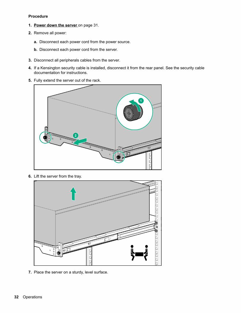
Procedure
1. Power down the server on page 31.
2. Remove all power:
a. Disconnect each power cord from the power source.
b. Disconnect each power cord from the server.
3. Disconnect all peripherals cables from the server.
4. If a Kensington security cable is installed, disconnect it from the rear panel. See the security cabledocumentation for instructions.
5. Fully extend the server out of the rack.
6. Lift the server from the tray.
7. Place the server on a sturdy, level surface.
32 Operations

Remove the access panelWARNING: To reduce the risk of personal injury from hot surfaces, allow the drives and the internalsystem components to cool before touching them.
CAUTION: For proper cooling, do not operate the server without the access panel, baffles, expansionslot covers, or blanks installed. If the server supports hot-plug components, minimize the amount of timethe access panel is open.
CAUTION: To prevent damage to electrical components, properly ground the server before beginningany installation procedure. Improper grounding can cause electrostatic discharge.
Procedure
1. Power down the server on page 31.
2. Remove all power:
a. Disconnect each power cord from the power source.
b. Disconnect each power cord from the server.
3. Disconnect all peripherals cables from the server.
4. If a Kensington security cable is installed, disconnect it from the rear panel. See the security cabledocumentation for instructions.
5. Do one of the following:
• Server in rack mode: Remove the server from the rack on page 31.
• Server in tower mode: Place the server on its side with the access panel facing up.
6. Remove the access panel:
a. Loosen the access panel thumbscrews.
b. Slide and remove the access panel from the server.
Operations 33

Install the access panelProcedure
1. Install the access panel:
a. Place the access panel on the chassis, and slide it towards the front of the server.
b. Tighten the thumbscrews.
2. If a Kensington security cable was removed, connect it to the rear panel. See the security cabledocumentation for instructions.
3. Do one of the following:
34 Operations

• Server in rack mode: Install the server into the rack on page 49.
• Server in tower mode: Return the server to an upright position.
4. Connect each power cord to the server.
5. Connect each power cord to the power source.
6. Power up the server on page 31.
Remove the front bezelProcedure
1. If the bezel is locked, power down the server.
2. Remove all power:
a. Disconnect each power cord from the power source.
b. Disconnect each power cord from the server.
3. If the front bezel is locked by the internal locker, remove the access panel.
4. Open and remove the front bezel:
a. Slide up the internal locker.
b. Open the front bezel.
c. Remove the front bezel.
Install the front bezelProcedure
1. Install and close the front bezel.
Operations 35

2. Do one of the following:
• Lock the internal locker.
• Leave the internal locker in unlock position if you want to access the front panel any time withoutremoving the access panel.
3. Install the access panel on page 34.
4. Do one of the following:
• Server in rack mode: Install the server into the rack on page 49.
• Server in tower mode: Return the server to an upright position.
5. Connect each power cord to the server.
6. Connect each power cord to the power source.
7. Power up the server on page 31.
Remove the PCI air baffleProcedure
1. Power down the server on page 31.
2. Remove all power:
a. Disconnect each power cord from the power source.
b. Disconnect each power cord from the server.
3. Do one of the following:
• Server in rack mode: Remove the server from the rack on page 31.
• Server in tower mode: Place the server on its side with the access panel facing up.
36 Operations

4. Remove the access panel on page 33.
5. Remove the PCI air baffle.
Install the PCI air baffleCAUTION: For proper cooling do not operate the server without the access panel, baffles, expansionslot covers, or blanks installed.
Procedure
1. Install the PCI air baffle.
2. Install the front bezel on page 35.
3. Install the access panel on page 34.
4. Do one of the following:
Operations 37

• Server in rack mode: Install the server into the rack on page 49.
• Server in tower mode: Return the server to an upright position.
5. Connect each power cord to the server.
6. Connect each power cord to the power source.
7. Power up the server on page 31.
Remove the system air baffleProcedure
1. Power down the server on page 31.
2. Remove all power:
a. Disconnect each power cord from the power source.
b. Disconnect each power cord from the server.
3. Do one of the following:
• Server in rack mode: Remove the server from the rack on page 31.
• Server in tower mode: Place the server on its side with the access panel facing up.
4. Remove the access panel on page 33.
5. Remove the PCI air baffle on page 36.
6. Remove the system air baffle.
Install the system air baffleCAUTION: For proper cooling do not operate the server without the access panel, baffles, expansionslot covers, or blanks installed.
38 Operations

Procedure
1. Install the system air baffle.
2. Install the PCI air baffle on page 37
3. Install the front bezel on page 35.
4. Install the access panel on page 34.
5. Do one of the following:
• Server in rack mode: Install the server into the rack on page 49.
• Server in tower mode: Return the server to an upright position.
6. Connect each power cord to the server.
7. Connect each power cord to the power source.
8. Power up the server on page 31.
Operations 39

Hardware options installationProduct QuickSpecs
For more information about product features, specifications, options, configurations, and compatibility, see theproduct QuickSpecs on the Hewlett Packard Enterprise website (http://www.hpe.com/info/qs).
IntroductionIf more than one option is being installed, read the installation instructions for all the hardware options andidentify similar steps to streamline the installation process.
WARNING: To reduce the risk of personal injury from hot surfaces, allow the drives and the internalsystem components to cool before touching them.
CAUTION: To prevent damage to electrical components, properly ground the server before beginningany installation procedure. Improper grounding can cause electrostatic discharge.
Drive options
Drive installation guidelinesDepending on the configuration, the server supports SAS and SATA drives.
Observe the following general guidelines:
• The system automatically sets all drive numbers.
• If only one drive is used, install it in the bay with the lowest drive number.
For drive numbering, see Drive numbering on page 18.
• Drives with the same capacity provide the greatest storage space efficiency when grouped into the samedrive array.
Drive support informationDepending on the drive cage installed, the server supports the following drive types:
• Non-hot-plug LFF SATA drives
• Hot-plug LFF SATA or SAS drives
• Hot-plug SFF SATA or SAS drives
The server supports up to 16 drives in SFF configuration and 8 drives in LFF configuration.
The embedded HPE Smart Array S100i SR Gen10 Controller supports SATA drive installation. For SASsupport, install a type-p standup plug-in Smart Array controller option.
Installing an LFF non-hot-plug drive
Prerequisites
Before you perform this procedure, make sure that you have T-15 Torx screwdriver available.
40 Hardware options installation
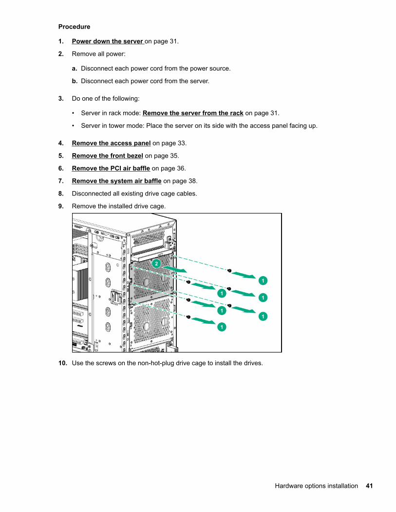
Procedure
1. Power down the server on page 31.
2. Remove all power:
a. Disconnect each power cord from the power source.
b. Disconnect each power cord from the server.
3. Do one of the following:
• Server in rack mode: Remove the server from the rack on page 31.
• Server in tower mode: Place the server on its side with the access panel facing up.
4. Remove the access panel on page 33.
5. Remove the front bezel on page 35.
6. Remove the PCI air baffle on page 36.
7. Remove the system air baffle on page 38.
8. Disconnected all existing drive cage cables.
9. Remove the installed drive cage.
10. Use the screws on the non-hot-plug drive cage to install the drives.
Hardware options installation 41

11. Install the 4 LFF non-hot-plug drive cage assembly.
12. Connect the drive cables.
13. Install the system air baffle on page 38.
14. Install the PCI air baffle on page 37.
15. Install the front bezel on page 35.
16. Install the access panel on page 34.
17. Do one of the following:
• Server in rack mode: Install the server into the rack on page 49.
• Server in tower mode: Return the server to an upright position.
18. Connect each power cord to the server.
42 Hardware options installation

19. Connect each power cord to the power source.
20. Power up the server on page 31.
The installation is complete.
To configure arrays, see the HPE Smart Array SR Gen10 Configuration Guide at the Hewlett PackardEnterprise website.
Installing an LFF hot-plug drive
CAUTION: To prevent improper cooling and thermal damage, do not operate the rack unless all devicebays are populated with either a component or a blank.
PrerequisitesBefore you perform this procedure:
• Verify that the LFF hot-plug drive cage is installed.
• Make sure that you have the LFF hot-plug drive option is available.
Procedure
1. Open the front bezel.
2. Remove the drive blank.
3. Prepare the drive.
4. Install the drive.
Hardware options installation 43

5. If the drive is installed in an empty drive cage after the initial system boot, reboot the system to maintainoptimal ventilation.
6. Determine the status of the drive from the drive LED definitions.
7. Close the front bezel.
The installation is complete.
To configure arrays, see the HPE Smart Array SR Gen10 Configuration Guide at the Hewlett PackardEnterprise website.
Installing an SFF hot-plug drive
CAUTION: To prevent improper cooling and thermal damage, do not operate the rack unless all devicebays are populated with either a component or a blank.
PrerequisitesBefore you perform this procedure:
• Verify that the SFF hot-plug drive cage is installed.
• Make sure that you have the SFF hot-plug drive option is available.
• If you are installing an SFF hot-plug SAS drive or SSD, make sure that the redundant fan option kit isinstalled.
Procedure
1. Open the front bezel.
2. Remove the drive blank.
3. Prepare the drive.
44 Hardware options installation
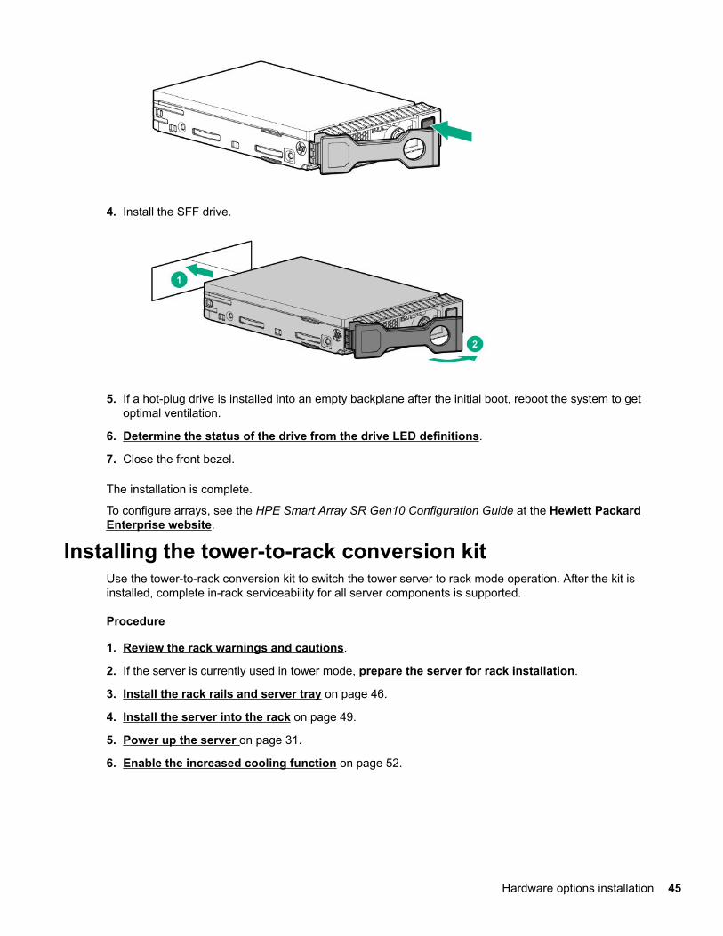
4. Install the SFF drive.
5. If a hot-plug drive is installed into an empty backplane after the initial boot, reboot the system to getoptimal ventilation.
6. Determine the status of the drive from the drive LED definitions.
7. Close the front bezel.
The installation is complete.
To configure arrays, see the HPE Smart Array SR Gen10 Configuration Guide at the Hewlett PackardEnterprise website.
Installing the tower-to-rack conversion kitUse the tower-to-rack conversion kit to switch the tower server to rack mode operation. After the kit isinstalled, complete in-rack serviceability for all server components is supported.
Procedure
1. Review the rack warnings and cautions.
2. If the server is currently used in tower mode, prepare the server for rack installation.
3. Install the rack rails and server tray on page 46.
4. Install the server into the rack on page 49.
5. Power up the server on page 31.
6. Enable the increased cooling function on page 52.
Hardware options installation 45
Prepare the server for rack installation
Prerequisites
Before you perform this procedure, make sure that you have T-15 Torx screwdriver available.
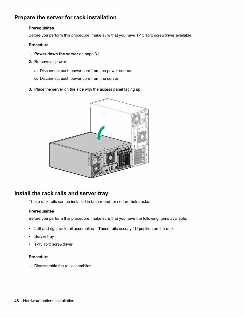
Procedure
1. Power down the server on page 31.
2. Remove all power:
a. Disconnect each power cord from the power source.
b. Disconnect each power cord from the server.
3. Place the server on the side with the access panel facing up.
Install the rack rails and server trayThese rack rails can be installed in both round- or square-hole racks.
Prerequisites
Before you perform this procedure, make sure that you have the following items available:
• Left and right rack rail assemblies – These rails occupy 1U position on the rack.
• Server tray
• T-15 Torx screwdriver
Procedure
1. Disassemble the rail assemblies:
46 Hardware options installation

a. Pull out the inner rail until it is fully extended .
b. Slide and hold the white release tab in the direction shown, and then remove the inner sliding rail fromthe outer mounting rail.
c. Repeat steps a–b on the other rail assembly.
2. Install the sliding rails on the server tray:
a. Align the notches on the rail with the pins on the side.
b. Slide the rail towards the rear of the tray to lock it into place.
c. Repeat steps a–b on the other inner rail.
3. Locate the orientation markers on the mounting rails:
Hardware options installation 47

• The front end of the rails is marked FRONT.
• The rear end of the rails is marked with L for left and R for right.
4. Fasten the mounting rails to the rack columns:
a. Retract and hold the rear retention bracket.
b. Insert the pegs on the mounting flange into the rack holes.
c. Release the rear retention bracket.
d. Retract and hold the front retention bracket.
e. Insert the pegs on the mounting flange into the rack holes.
f. Release the front retention bracket.
48 Hardware options installation

g. Repeat steps a-f to fasten the other mounting rail.
h. Make sure that both rails are mounted at the same vertical position on both sides of the rack.
5. Slide the server tray into the rack.
The rails will click and lock into place when the tray is properly engaged.
Install the server into the rack
Prerequisites
Before you perform this procedure, make sure that you have T-15 Torx screwdriver available.
Procedure
1. Grasp the tray notch and extend the server tray out of the rack.
Hardware options installation 49
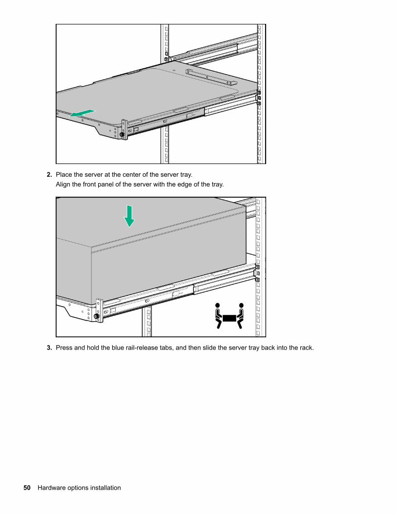
2. Place the server at the center of the server tray.Align the front panel of the server with the edge of the tray.
3. Press and hold the blue rail-release tabs, and then slide the server tray back into the rack.
50 Hardware options installation

4. Tighten the server tray thumbscrews.
5. Connect all peripheral cables and power cords to the rear panel.
6. Secure the power cord with the strain relief strap. Roll the extra length of the strap around the power inputmodule handle.
Hardware options installation 51
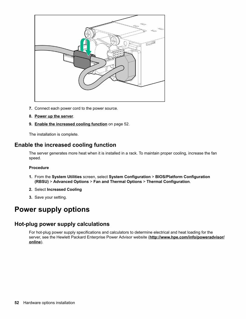
7. Connect each power cord to the power source.
8. Power up the server.
9. Enable the increased cooling function on page 52.
The installation is complete.
Enable the increased cooling functionThe server generates more heat when it is installed in a rack. To maintain proper cooling, increase the fanspeed.
Procedure
1. From the System Utilities screen, select System Configuration > BIOS/Platform Configuration(RBSU) > Advanced Options > Fan and Thermal Options > Thermal Configuration.
2. Select Increased Cooling
3. Save your setting.
Power supply options
Hot-plug power supply calculationsFor hot-plug power supply specifications and calculators to determine electrical and heat loading for theserver, see the Hewlett Packard Enterprise Power Advisor website (http://www.hpe.com/info/poweradvisor/online).
52 Hardware options installation

Power supply warnings and cautions
WARNING: To reduce the risk of electric shock or damage to the equipment:
• Do not disable the power cord grounding plug. The grounding plug is an important safety feature.
• Plug the power cord into a grounded (earthed) electrical outlet that is easily accessible at all times.
• Unplug the power cord from the power supply to disconnect power to the equipment.
• Do not route the power cord where it can be walked on or pinched by items placed against it. Payparticular attention to the plug, electrical outlet, and the point where the cord extends from theserver.
WARNING: To reduce the risk of injury from electric shock hazards, do not open power supplies. Referall maintenance, upgrades, and servicing to qualified personnel
WARNING: To reduce the risk of personal injury from hot surfaces, allow the drives and the internalsystem components to cool before touching them.
CAUTION: To prevent damage to electrical components, properly ground the server before beginningany installation procedure. Improper grounding can cause electrostatic discharge.
CAUTION: Mixing different types of power supplies in the same server might:
• Limit or disable some power supply features including support for power redundancy
• Cause the system to become unstable and might shut down.
To ensure access to all available features, all power supplies in the same server should have the sameoutput and efficiency ratings. Verify that all power supplies have the same part number and label color.
Installing the ATX 550W non-hot-plug power supply
Prerequisites
Before you perform this procedure, make sure that you have the following items available:
• ATX 550W non-hot-plug power supply
• T-15 Torx screwdriver
Procedure
1. Power down the server on page 31.
2. Remove all power:
a. Disconnect each power cord from the power source.
b. Disconnect each power cord from the server.
3. Do one of the following:
Hardware options installation 53

• Server in rack mode: Remove the server from the rack on page 31.
• Server in tower mode: Place the server on its side with the access panel facing up.
4. Remove the access panel on page 33.
5. Remove the PCI air baffle on page 36.
6. Remove the system air baffle on page 38.
7. Disconnect all the power supply cables connected to the system board.
8. Remove the existing power supply.
9. Install the ATX 550W non-hot-plug power supply.
10. Connect the power supply cables.
11. Install the system air baffle on page 38.
12. Install the PCI air baffle on page 37.
54 Hardware options installation

13. Install the access panel on page 34.
14. Do one of the following:
• Server in rack mode: Install the server into the rack on page 49.
• Server in tower mode: Return the server to an upright position.
15. Connect each power cord to the server.
16. Connect each power cord to the power source.
17. Power up the server on page 31.
The installation is complete.
Redundant power supply enablement option
The RPS enablement option supports the installation of two Gen10 Flexible Slot (Flex Slot) power supplies.
Adding a second power supply provides redundant power support to the server if one power supply fails. Youdo not have to power down the server before removing or installing a redundant hot-plug power supply.
Installing the redundant power supply enablement option
Prerequisites
• Before installing the redundant power supply enablement, read the power supply warnings andcautions.
• Before you perform this procedure, make sure that you have the following items available:
◦ Redundant power supply enablement option
◦ Hot-plug power supply
◦ T-15 Torx screwdriver
Procedure
1. Power down the server on page 31.
2. Remove all power:
a. Disconnect each power cord from the power source.
b. Disconnect each power cord from the server.
3. Do one of the following:
• Server in rack mode: Remove the server from the rack on page 31.
• Server in tower mode: Place the server on its side with the access panel facing up.
4. Remove the access panel on page 33.
5. Remove the system air baffle on page 38.
6. Disconnect all power supply cables from the system board, drive cages, and devices.
Hardware options installation 55

7. Remove the non-hot-plug power supply.
8. Install the RPS bracket.
9. Install the RPS backplane.
56 Hardware options installation

10. Connect the RPS backplane cables.
11. Install a hot-plug power supply in the power supply bay 1.
When facing the rear of the server in an upright position, the upper level of power supply bay is bay 1and the lower level is bay 2.
12. To enable power redundancy in the server, install a second power supply in the power supply bay 2:
a. Remove the power supply blank from bay 2.
Hardware options installation 57
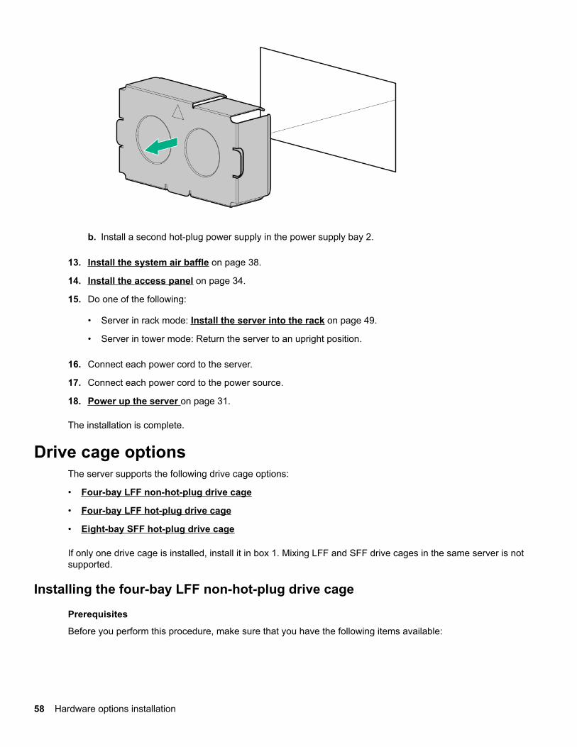
b. Install a second hot-plug power supply in the power supply bay 2.
13. Install the system air baffle on page 38.
14. Install the access panel on page 34.
15. Do one of the following:
• Server in rack mode: Install the server into the rack on page 49.
• Server in tower mode: Return the server to an upright position.
16. Connect each power cord to the server.
17. Connect each power cord to the power source.
18. Power up the server on page 31.
The installation is complete.
Drive cage optionsThe server supports the following drive cage options:
• Four-bay LFF non-hot-plug drive cage
• Four-bay LFF hot-plug drive cage
• Eight-bay SFF hot-plug drive cage
If only one drive cage is installed, install it in box 1. Mixing LFF and SFF drive cages in the same server is notsupported.
Installing the four-bay LFF non-hot-plug drive cage
Prerequisites
Before you perform this procedure, make sure that you have the following items available:
58 Hardware options installation
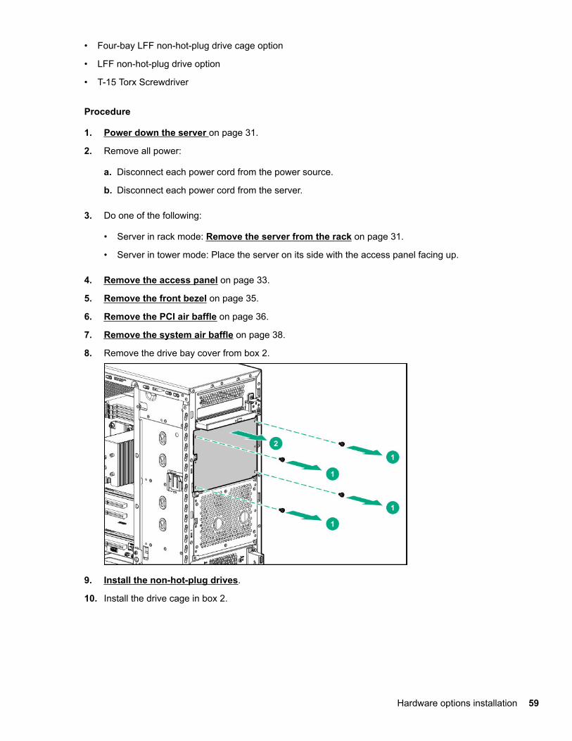
• Four-bay LFF non-hot-plug drive cage option
• LFF non-hot-plug drive option
• T-15 Torx Screwdriver
Procedure
1. Power down the server on page 31.
2. Remove all power:
a. Disconnect each power cord from the power source.
b. Disconnect each power cord from the server.
3. Do one of the following:
• Server in rack mode: Remove the server from the rack on page 31.
• Server in tower mode: Place the server on its side with the access panel facing up.
4. Remove the access panel on page 33.
5. Remove the front bezel on page 35.
6. Remove the PCI air baffle on page 36.
7. Remove the system air baffle on page 38.
8. Remove the drive bay cover from box 2.
9. Install the non-hot-plug drives.
10. Install the drive cage in box 2.
Hardware options installation 59

11. Connect the drive cables.
12. Install the system air baffle on page 38.
13. Install the PCI air baffle on page 37.
14. Install the front bezel on page 35.
15. Install the access panel on page 34.
16. Do one of the following:
• Server in rack mode: Install the server into the rack on page 49.
• Server in tower mode: Return the server to an upright position.
17. Connect each power cord to the server.
18. Connect each power cord to the power source.
19. Power up the server on page 31.
The installation is complete.
Installing the four-bay LFF hot-plug drive cageThe four-bay LFF hot-plug drive cage can be installed in both box 1 and box 2.
Prerequisites
Before you perform this procedure, make sure that you have the following items available:
• Four-bay LFF hot-plug drive cage option
• LFF hot-plug drive option
• T-15 Torx Screwdriver
60 Hardware options installation

Procedure
1. Power down the server on page 31.
2. Remove all power:
a. Disconnect each power cord from the power source.
b. Disconnect each power cord from the server.
3. Do one of the following:
• Server in rack mode: Remove the server from the rack on page 31.
• Server in tower mode: Place the server on its side with the access panel facing up.
4. Remove the access panel on page 33.
5. Remove the front bezel on page 35.
6. Remove the PCI air baffle on page 36.
7. Remove the system air baffle on page 38.
8. Disconnect all existing drive cage cables.
9. Remove the installed drive cage assembly.
10. Install the drive cage in box 1.
Hardware options installation 61

11. Connect the drive cables.
12. Install the LFF hot-plug drives.
13. Install the system air baffle on page 38.
14. Install the PCI air baffle on page 37.
15. Install the front bezel on page 35.
16. Install the access panel on page 34.
17. Do one of the following:
• Server in rack mode: Install the server into the rack on page 49.
• Server in tower mode: Return the server to an upright position.
18. Connect each power cord to the server.
19. Connect each power cord to the power source.
20. Power up the server on page 31.
The installation is complete.
Installing the eight-bay SFF hot-plug drive cageThe eight-bay SFF hot-plug drive cage can be installed in both box 1 and box 2.
Prerequisites
Before you perform this procedure, make sure that you have the following items available:
• Eight-bay SFF hot-plug drive cage option
• SFF hot-plug drive option
• T-15 Torx Screwdriver
62 Hardware options installation
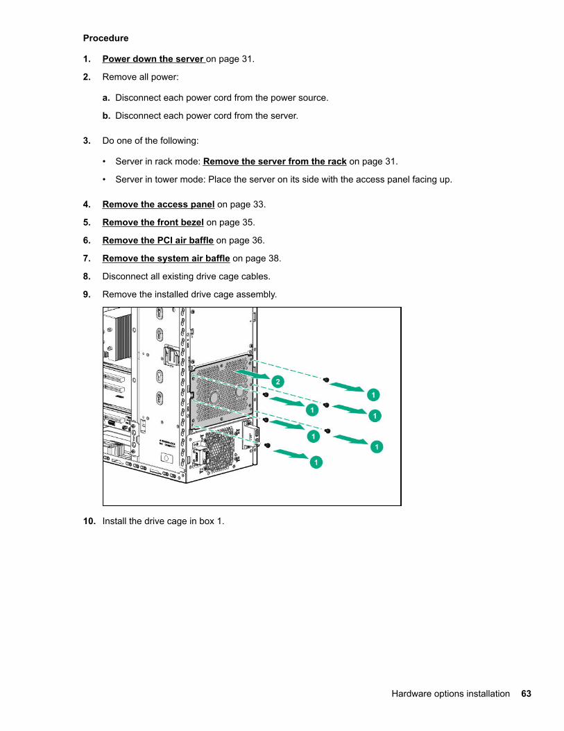
Procedure
1. Power down the server on page 31.
2. Remove all power:
a. Disconnect each power cord from the power source.
b. Disconnect each power cord from the server.
3. Do one of the following:
• Server in rack mode: Remove the server from the rack on page 31.
• Server in tower mode: Place the server on its side with the access panel facing up.
4. Remove the access panel on page 33.
5. Remove the front bezel on page 35.
6. Remove the PCI air baffle on page 36.
7. Remove the system air baffle on page 38.
8. Disconnect all existing drive cage cables.
9. Remove the installed drive cage assembly.
10. Install the drive cage in box 1.
Hardware options installation 63
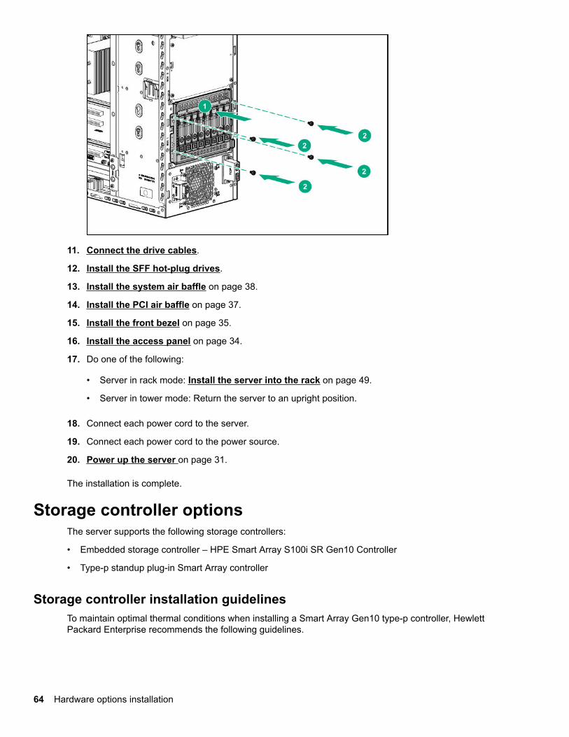
11. Connect the drive cables.
12. Install the SFF hot-plug drives.
13. Install the system air baffle on page 38.
14. Install the PCI air baffle on page 37.
15. Install the front bezel on page 35.
16. Install the access panel on page 34.
17. Do one of the following:
• Server in rack mode: Install the server into the rack on page 49.
• Server in tower mode: Return the server to an upright position.
18. Connect each power cord to the server.
19. Connect each power cord to the power source.
20. Power up the server on page 31.
The installation is complete.
Storage controller optionsThe server supports the following storage controllers:
• Embedded storage controller – HPE Smart Array S100i SR Gen10 Controller
• Type-p standup plug-in Smart Array controller
Storage controller installation guidelinesTo maintain optimal thermal conditions when installing a Smart Array Gen10 type-p controller, HewlettPackard Enterprise recommends the following guidelines.
64 Hardware options installation

Storage controller option Recommended PCIe slot Cable option
E208i-p
E208e-p
Slot 1, 3 or 4 Mini-SAS cable option
P408i-p
P408e-p
Slot 1, 3 or 4 Mini-SAS cable option
Installing the Smart Array storage controller
Prerequisites
Before you perform this procedure, make sure that you have the following items available:
• Controller option
• T-15 Torx screwdriver
Procedure
1. Back up all server data.
2. Power down the server on page 31.
3. Remove all power:
a. Disconnect each power cord from the power source.
b. Disconnect each power cord from the server.
4. Do one of the following:
• Server in rack mode: Remove the server from the rack on page 31.
• Server in tower mode: Place the server on its side with the access panel facing up.
5. Remove the access panel on page 33.
6. Remove the PCI air baffle on page 36.
7. Remove the system air baffle on page 38.
8. Open the PCIe slot cover retainer and remove a slot blank.
Hardware options installation 65

9. Install the Smart Array controller and close the slot cover retainer.
10. Make sure that the controller board is firmly seated in the slot.
11. Cable the controller.
12. If you are planning to install the Smart Storage Battery, install it now.
13. Install the system air baffle on page 38.
14. Install the PCI air baffle on page 37.
15. Install the access panel on page 34.
16. Do one of the following:
• Server in rack mode: Install the server into the rack on page 49.
• Server in tower mode: Return the server to an upright position.
17. Connect each power cord to the server.
66 Hardware options installation

18. Connect each power cord to the power source.
19. Power up the server on page 31.
20. Configure the storage controller.
The installation is complete.
Configuring an HPE Smart Array Gen10 controller
Procedure
1. Power up the server on page 31.
2. If you are running the server in UEFI Boot Mode, select the boot options.
3. Update the drive firmware if it is not the latest revision.
4. (Optional) If running the server in Legacy Boot Mode, set the controller as the boot controller.
5. (Optional) If running the server in Legacy Boot Mode, change the controller boot order.
6. If the new controller is not the new boot device, install the device drivers.
7. If the controller firmware is not the latest version, use SPP to update it.
8. Use UEFI System Utilities or HPE Smart Storage Administrator (HPE SSA) to create arrays and logicaldrives.
See the following resources for more information:
• SPP – See the product documentation in the information library:
http://www.hpe.com/info/spp/docs
• UEFI System Utilities or HPE Smart Storage Administrator – See the following guide in the informationlibrary (http://www.hpe.com/info/smartstorage-docs):
HPE Smart Array SR Gen10 Configuration Guide
Smart Storage Battery optionThe Smart Storage Battery is a centralized backup source and is required to back up the write cache contentonto flash memory on the Smart Array P-class Gen10 controllers if there was an unplanned server powerloss. In this server, the 96 W, 260 mm battery supports up to 24 devices.
After the battery is installed, it might take up to one hour to charge. Controller features requiring backuppower are not enabled until the battery is capable of supporting the backup power.
Installing a Smart Storage Battery
Procedure
1. Back up all server data.
2. Power down the server on page 31.
3. Remove all power:
Hardware options installation 67

a. Disconnect each power cord from the power source.
b. Disconnect each power cord from the server.
4. Do one of the following:
• Server in rack mode: Remove the server from the rack on page 31.
• Server in tower mode: Place the server on its side with the access panel facing up.
5. Remove the access panel on page 33.
6. Remove the PCI air baffle on page 36.
7. Remove the system air baffle on page 38.
8. Remove the slot covers.
9. Install the Smart Storage Battery holder.
68 Hardware options installation

10. Install the Smart Storage Battery:
a. Install the Smart Storage Battery into the holder.
b. Route the battery cable through the cable clip and connect to the system board connector.
11. Connect the storage controller backup power connectors.
12. Install the system air baffle on page 38.
13. Install the PCI air baffle on page 37.
14. Install the access panel on page 34.
15. Do one of the following:
• Server in rack mode: Install the server into the rack on page 49.
• Server in tower mode: Return the server to an upright position.
16. Connect each power cord to the server.
17. Connect each power cord to the power source.
18. Power up the server on page 31.
The installation is complete.
Redundant fan option kitThe redundant fan option kit contains the redundant system and PCI fans. Redundant fan mode is required tomeet the system thermal requirements under the following conditions:
• Server with the following options installed:
Hardware options installation 69

◦ SFF hot-plug SAS SSD
◦ SFF hot-plug SAS drives in box 2
• The ambient temperature reaches 35°C (95°F) to 40°C (104°F).
Installing the redundant fans
Prerequisites
Before you perform this procedure, make sure that:
• The redundant power supply is installed.
• You have a T-15 Torx screwdriver available.
Procedure
1. Power down the server on page 31.
2. Remove all power:
a. Disconnect each power cord from the power source.
b. Disconnect each power cord from the server.
3. Do one of the following:
• Server in rack mode: Remove the server from the rack on page 31.
• Server in tower mode: Place the server on its side with the access panel facing up.
4. Remove the access panel on page 33.
5. Remove the front bezel on page 35.
6. Remove the PCI air baffle on page 36.
7. Remove the system air baffle on page 38.
8. Remove the default PCI fan.
70 Hardware options installation

9. Install the redundant PCI fan:
a. Insert the fan guard pins into the front chassis openings.
b. Tighten the four T-15 screws.
10. Connect the redundant PCI fan cables.
11. Remove the default system fan.
Hardware options installation 71
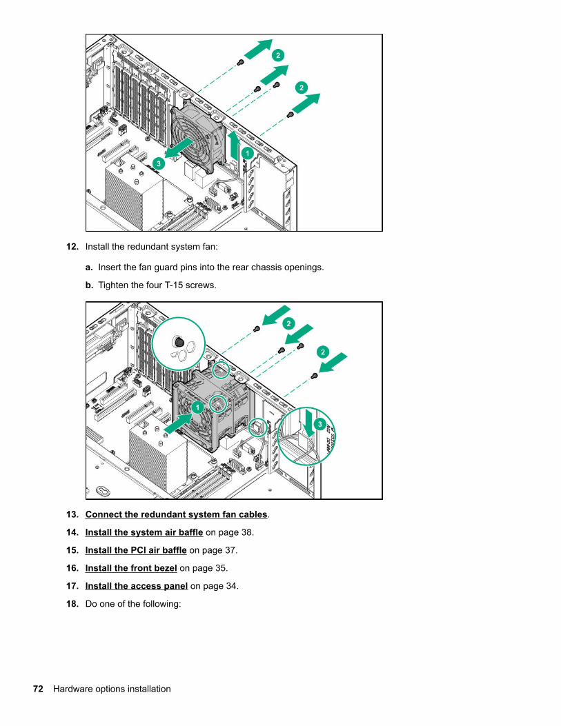
12. Install the redundant system fan:
a. Insert the fan guard pins into the rear chassis openings.
b. Tighten the four T-15 screws.
13. Connect the redundant system fan cables.
14. Install the system air baffle on page 38.
15. Install the PCI air baffle on page 37.
16. Install the front bezel on page 35.
17. Install the access panel on page 34.
18. Do one of the following:
72 Hardware options installation

• Server in rack mode: Install the server into the rack on page 49.
• Server in tower mode: Return the server to an upright position.
19. Connect each power cord to the server.
20. Connect each power cord to the power source.
21. Power up the server on page 31.
The installation is complete.
Memory optionsIMPORTANT: This server does not support mixing LRDIMMs and RDIMMs. Attempting to mix anycombination of these DIMMs can cause the server to halt during BIOS initialization. All memory installedin the server must be of the same type.
DIMM population informationFor specific DIMM population information, see the DIMM population guidelines on the Hewlett PackardEnterprise website (http://www.hpe.com/docs/memory-population-rules).
HPE Smart Memory speed informationFor more information about memory speed information, see the Hewlett Packard Enterprise website (https://www.hpe.com/docs/memory-speed-table).
Installing a DIMMOnly the 32 GB, dual-rank x4 PC4-2666V-R DIMM supports the ADDDC RAS feature.
Procedure
1. Power down the server on page 31.
2. Remove all power:
a. Disconnect each power cord from the power source.
b. Disconnect each power cord from the server.
3. Do one of the following:
• Server in rack mode: Remove the server from the rack on page 31.
• Server in tower mode: Place the server on its side with the access panel facing up.
4. Remove the access panel on page 33.
5. Remove the PCI air baffle on page 36.
6. Remove the system air baffle on page 38.
7. Install the DIMM.
Hardware options installation 73

a. Open the DIMM slot latches.
b. Align the notch on the bottom edge of the DIMM with the keyed surface of the DIMM slot, and theninstall the DIMM into the slot.
8. Install the system air baffle on page 38.
9. Install the PCI air baffle on page 37.
10. Install the access panel on page 34.
11. Do one of the following:
• Server in rack mode: Install the server into the rack on page 49.
• Server in tower mode: Return the server to an upright position.
12. Connect each power cord to the server.
13. Connect each power cord to the power source.
14. Power up the server on page 31.
The installation is complete.
M.2 SSD enablement optionThe M.2 SSD enablement board is supported in the PCIe3 expansion slots 1, 3, and 4. This enablementboard is not a detectable option in the System Utilities > System Configuration > BIOS/PlatformConfiguration (RBSU) > Storage Options > PCIe Storage Boot Policy setting.
Installing an M.2 SATA SSD
Prerequisites
Before you perform this procedure, make sure that you have the following items available:
74 Hardware options installation

• M.2 SSD option
• T-15 Torx screwdriver
• Phillips No.1 screwdriver
Procedure
1. Power down the server on page 31.
2. Remove all power:
a. Disconnect each power cord from the power source.
b. Disconnect each power cord from the server.
3. Do one of the following:
• Server in rack mode: Remove the server from the rack on page 31.
• Server in tower mode: Place the server on its side with the access panel facing up.
4. Remove the access panel on page 33.
5. Remove the PCI air baffle on page 36.
6. Remove the system air baffle on page 38.
7. Install the SSD on the M.2 SSD enablement board:
a. Insert the SSD into the SSD slot at a 45° angle.
b. Carefully press the SSD down to the horizontal position.
c. Secure the SSD with a screw.
d. If you are installing a second SSD, repeat steps a–b.
8. Open the PCIe slot cover retainer and remove a slot blank.
Hardware options installation 75
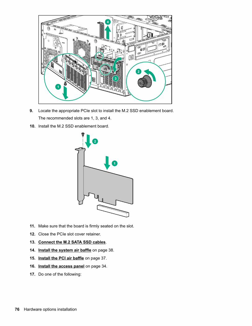
9. Locate the appropriate PCIe slot to install the M.2 SSD enablement board.
The recommended slots are 1, 3, and 4.
10. Install the M.2 SSD enablement board.
11. Make sure that the board is firmly seated on the slot.
12. Close the PCIe slot cover retainer.
13. Connect the M.2 SATA SSD cables.
14. Install the system air baffle on page 38.
15. Install the PCI air baffle on page 37.
16. Install the access panel on page 34.
17. Do one of the following:
76 Hardware options installation

• Server in rack mode: Install the server into the rack on page 49.
• Server in tower mode: Return the server to an upright position.
18. Connect each power cord to the server.
19. Connect each power cord to the power source.
20. Power up the server on page 31.
The installation is complete.
To configure the M.2 SATA SSDs, see the HPE Smart Array SR Gen10 Configuration Guide at the HewlettPackard Enterprise website.
GPU optionThe GPU is supported in the PCIe3 expansion slots 1 and 2.
For a list of specific GPU models supported, see the product QuickSpecs on the server product page at http://www.hpe.com/servers/ml110-gen10.
75 W GPUs draw power from the PCIe slot; auxiliary power connection is not required. Higher wattage GPUsmight require an external auxiliary power connection to fully power up the GPU. See the GPU documentationfor the specific auxiliary power connections required for that model.
Installing the GPU option
Prerequisites
Before installing this option, make sure that you have the following items available:
• GPU option kit
• T-15 Torx screwdriver
Procedure
1. Back up all server data.
2. Power down the server on page 31.
3. Remove all power:
a. Disconnect each power cord from the power source.
b. Disconnect each power cord from the server.
4. Do one of the following:
• Server in rack mode: Remove the server from the rack on page 31.
• Server in tower mode: Place the server on its side with the access panel facing up.
5. Remove the access panel on page 33.
6. Remove the PCI air baffle on page 36.
7. Remove the system air baffle on page 38.
8. Open the PCIe slot cover retainer and remove a slot blank.
Hardware options installation 77

9. Install the GPU.
10. Make sure that the GPU is firmly seated in the slot.
11. Close the PCIe slot cover retainer.
12. Install the system air baffle on page 38.
13. Install the PCI air baffle on page 37.
14. Install the access panel on page 34.
15. Do one of the following:
• Server in rack mode: Install the server into the rack on page 49.
• Server in tower mode: Return the server to an upright position.
16. Connect each power cord to the server.
78 Hardware options installation
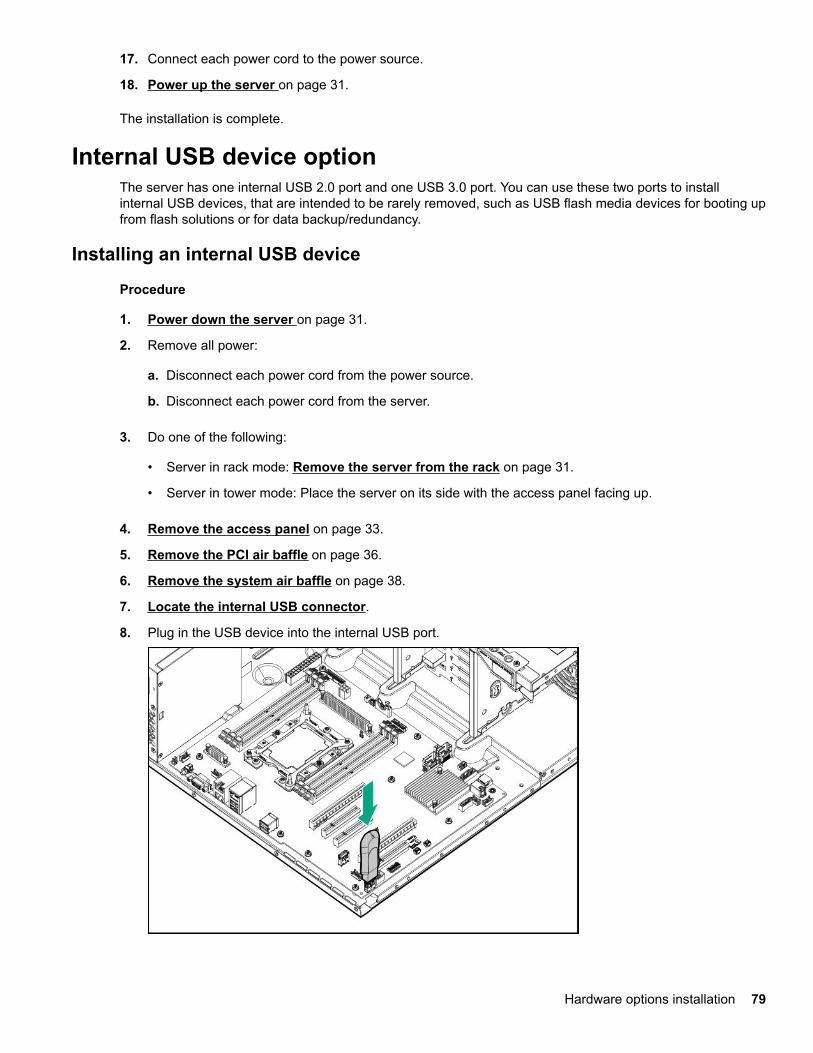
17. Connect each power cord to the power source.
18. Power up the server on page 31.
The installation is complete.
Internal USB device optionThe server has one internal USB 2.0 port and one USB 3.0 port. You can use these two ports to installinternal USB devices, that are intended to be rarely removed, such as USB flash media devices for booting upfrom flash solutions or for data backup/redundancy.
Installing an internal USB device
Procedure
1. Power down the server on page 31.
2. Remove all power:
a. Disconnect each power cord from the power source.
b. Disconnect each power cord from the server.
3. Do one of the following:
• Server in rack mode: Remove the server from the rack on page 31.
• Server in tower mode: Place the server on its side with the access panel facing up.
4. Remove the access panel on page 33.
5. Remove the PCI air baffle on page 36.
6. Remove the system air baffle on page 38.
7. Locate the internal USB connector.
8. Plug in the USB device into the internal USB port.
Hardware options installation 79

9. Install the system air baffle on page 38.
10. Install the PCI air baffle on page 37.
11. Install the access panel on page 34.
12. Do one of the following:
• Server in rack mode: Install the server into the rack on page 49.
• Server in tower mode: Return the server to an upright position.
13. Connect each power cord to the server.
14. Connect each power cord to the power source.
15. Power up the server on page 31.
The installation is complete.
Installing the serial port optionPrerequisites
Before you perform this procedure, make sure that you have the following items available:
• Serial port option
• T-15 Torx screwdriver
Procedure
1. Power down the server on page 31.
2. Remove all power:
a. Disconnect each power cord from the power source.
b. Disconnect each power cord from the server.
3. Do one of the following:
• Server in rack mode: Remove the server from the rack on page 31.
• Server in tower mode: Place the server on its side with the access panel facing up.
4. Remove the access panel on page 33.
5. Remove the PCI air baffle on page 36.
6. Remove the system air baffle on page 38.
7. Open the PCIe slot cover retainer and remove the fourth slot blank from the top.
80 Hardware options installation
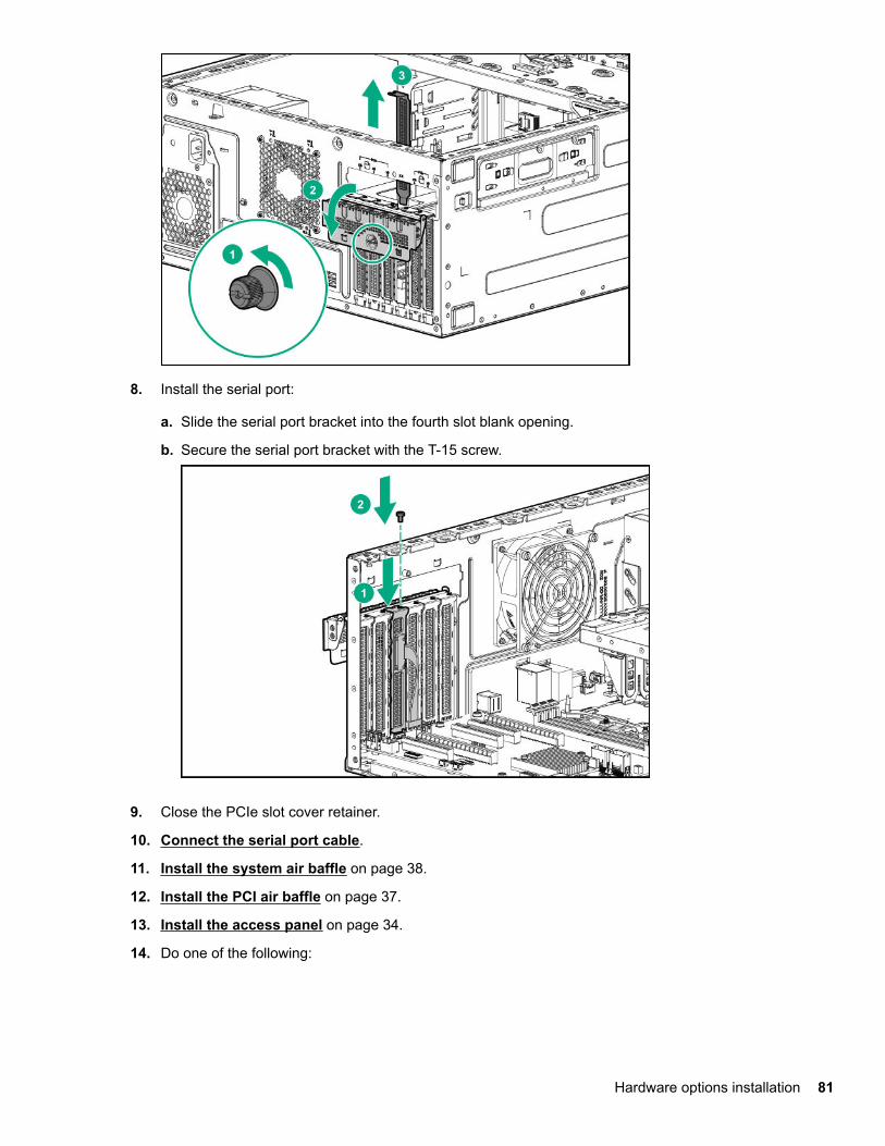
8. Install the serial port:
a. Slide the serial port bracket into the fourth slot blank opening.
b. Secure the serial port bracket with the T-15 screw.
9. Close the PCIe slot cover retainer.
10. Connect the serial port cable.
11. Install the system air baffle on page 38.
12. Install the PCI air baffle on page 37.
13. Install the access panel on page 34.
14. Do one of the following:
Hardware options installation 81
• Server in rack mode: Install the server into the rack on page 49.
• Server in tower mode: Return the server to an upright position.
15. Connect each power cord to the server.
16. Connect each power cord to the power source.
17. Power up the server on page 31.
The installation is complete.
HPE Trusted Platform Module 2.0 Gen10 optionOverview
Use these instructions to install and enable an HPE TPM 2.0 Gen10 Kit in a supported server. This option isnot supported on Gen9 and earlier servers.
This procedure includes three sections:
1. Installing the Trusted Platform Module board.
2. Enabling the Trusted Platform Module.
3. Retaining the recovery key/password.
HPE TPM 2.0 installation is supported with specific operating system support such as Microsoft® WindowsServer® 2012 R2 and later. For more information about operating system support, see the productQuickSpecs on the Hewlett Packard Enterprise website (http://www.hpe.com/info/qs). For more informationabout Microsoft® Windows® BitLocker Drive Encryption feature, see the Microsoft website (http://www.microsoft.com).
CAUTION: If the TPM is removed from the original server and powered up on a different server, datastored in the TPM including keys will be erased.
IMPORTANT: In UEFI Boot Mode, the HPE TPM 2.0 Gen10 Kit can be configured to operate as TPM2.0 (default) or TPM 1.2 on a supported server. In Legacy Boot Mode, the configuration can be changedbetween TPM 1.2 and TPM 2.0, but only TPM 1.2 operation is supported.
HPE Trusted Platform Module 2.0 Guidelines
CAUTION: Always observe the guidelines in this document. Failure to follow these guidelines can causehardware damage or halt data access.
Hewlett Packard Enterprise SPECIAL REMINDER: Before enabling TPM functionality on this system, youmust ensure that your intended use of TPM complies with relevant local laws, regulations and policies, andapprovals or licenses must be obtained if applicable.
For any compliance issues arising from your operation/usage of TPM which violates the above mentionedrequirement, you shall bear all the liabilities wholly and solely. Hewlett Packard Enterprise will not beresponsible for any related liabilities.
82 Hardware options installation

When installing or replacing a TPM, observe the following guidelines:
• Do not remove an installed TPM. Once installed, the TPM becomes a permanent part of the system board.
• When installing or replacing hardware, Hewlett Packard Enterprise service providers cannot enable theTPM or the encryption technology. For security reasons, only the customer can enable these features.
• When returning a system board for service replacement, do not remove the TPM from the system board.When requested, Hewlett Packard Enterprise Service provides a TPM with the spare system board.
• Any attempt to remove the cover of an installed TPM from the system board can damage the TPM cover,the TPM, and the system board.
• If the TPM is removed from the original server and powered up on a different server, data stored in theTPM including keys will be erased.
• When using BitLocker, always retain the recovery key/password. The recovery key/password is required tocomplete Recovery Mode after BitLocker detects a possible compromise of system integrity.
• Hewlett Packard Enterprise is not liable for blocked data access caused by improper TPM use. Foroperating instructions, see the TPM documentation or the encryption technology feature documentationprovided by the operating system.
Installing and enabling the HPE TPM 2.0 Gen10 Kit
Installing the Trusted Platform Module board
Preparing the server for installation
Procedure
1. Observe the following warnings:
WARNING: To reduce the risk of personal injury, electric shock, or damage to the equipment,remove power from the server by removing the power cord. The front panel Power On/Standbybutton does not shut off system power. Portions of the power supply and some internal circuitryremain active until AC power is removed.
WARNING: To reduce the risk of personal injury from hot surfaces, allow the drives and the internalsystem components to cool before touching them.
2. Update the system ROM.
Locate and download the latest ROM version from the Hewlett Packard Enterprise Support Centerwebsite. Follow the instructions on the website to update the system ROM.
3. Power down the server (Power down the server on page 31).
Hardware options installation 83

4. Remove all power:
a. Disconnect each power cord from the power source.
b. Disconnect each power cord from the server.
5. Do one of the following:
• Server in rack mode: Remove the server from the rack on page 31.
• Server in tower mode: Place the server on its side with the access panel facing up.
6. Remove the access panel on page 33.
7. Remove the PCI air baffle on page 36.
8. Remove the system air baffle on page 38.
9. Remove any components or cables that may prevent access to the TPM connector.
10. Proceed to Installing the TPM board and cover on page 84.
Installing the TPM board and cover
Procedure
1. Observe the following alerts:
CAUTION: If the TPM is removed from the original server and powered up on a different server, datastored in the TPM including keys will be erased.
CAUTION: The TPM is keyed to install only in the orientation shown. Any attempt to install the TPMin a different orientation might result in damage to the TPM or system board.
2. Align the TPM board with the key on the connector, and then install the TPM board. To seat the board,press the TPM board firmly into the connector. To locate the TPM connector on the system board, see theserver label on the access panel.
3. Install the TPM cover:
84 Hardware options installation

a. Line up the tabs on the cover with the openings on either side of the TPM connector.
b. To snap the cover into place, firmly press straight down on the middle of the cover.
4. Proceed to Preparing the server for operation on page 85.
Preparing the server for operation
Procedure
1. Install the system air baffle on page 38.
2. Install the PCI air baffle on page 37.
3. Install the access panel on page 34.
4. Do one of the following:
• Server in rack mode: Install the server into the rack on page 49.
• Server in tower mode: Return the server to an upright position.
5. Connect each power cord to the server.
6. Connect each power cord to the power source.
7. Power up the server on page 31.
Enabling the Trusted Platform ModuleWhen enabling the Trusted Platform module, observe the following guidelines:
• By default, the Trusted Platform Module is enabled as TPM 2.0 when the server is powered on afterinstalling it.
• In UEFI Boot Mode, the Trusted Platform Module can be configured to operate as TPM 2.0 or TPM 1.2.
• In Legacy Boot Mode, the Trusted Platform Module configuration can be changed between TPM 1.2 andTPM 2.0, but only TPM 1.2 operation is supported.
Hardware options installation 85
Enabling the Trusted Platform Module as TPM 2.0
Procedure
1. During the server startup sequence, press the F9 key to access System Utilities.
2. From the System Utilities screen, select System Configuration > BIOS/Platform Configuration (RBSU)> Server Security > Trusted Platform Module options.
3. Verify the following:
• "Current TPM Type" is set to TPM 2.0.
• "Current TPM State" is set to Present and Enabled.
• "TPM Visibility" is set to Visible.
4. If changes were made in the previous step, press the F10 key to save your selection.
5. If F10 was pressed in the previous step, do one of the following:
• If in graphical mode, click Yes.
• If in text mode, press the Y key.
6. Press the ESC key to exit System Utilities.
7. If changes were made and saved, the server prompts for reboot request. Press the Enter key to confirmreboot.
If the following actions were performed, the server reboots a second time without user input. During thisreboot, the TPM setting becomes effective.
• Changing from TPM 1.2 and TPM 2.0
• Changing TPM bus from FIFO to CRB
• Enabling or disabling TPM
• Clearing the TPM
8. Enable TPM functionality in the OS, such as Microsoft Windows BitLocker or measured boot.
For more information, see the Microsoft website.
Enabling the Trusted Platform Module as TPM 1.2
Procedure
1. During the server startup sequence, press the F9 key to access System Utilities.
2. From the System Utilities screen select System Configuration > BIOS/Platform Configuration (RBSU)> Server Security > Trusted Platform Module options.
3. Change the "TPM Mode Switch Operation" to TPM 1.2.
4. Verify "TPM Visibility" is Visible.
5. Press the F10 key to save your selection.
86 Hardware options installation
6. When prompted to save the change in System Utilities, do one of the following:
• If in graphical mode, click Yes.
• If in text mode, press the Y key.
7. Press the ESC key to exit System Utilities.
The server reboots a second time without user input. During this reboot, the TPM setting becomeseffective.
8. Enable TPM functionality in the OS, such as Microsoft Windows BitLocker or measured boot.
For more information, see the Microsoft website.
Retaining the recovery key/passwordThe recovery key/password is generated during BitLocker setup, and can be saved and printed afterBitLocker is enabled. When using BitLocker, always retain the recovery key/password. The recovery key/password is required to enter Recovery Mode after BitLocker detects a possible compromise of systemintegrity.
To help ensure maximum security, observe the following guidelines when retaining the recovery key/password:
• Always store the recovery key/password in multiple locations.
• Always store copies of the recovery key/password away from the server.
• Do not save the recovery key/password on the encrypted hard drive.
Hardware options installation 87
CablingCabling guidelines
The cable colors in the cabling diagrams used in this chapter are for illustration purposes only. Most of theserver cables are black.
Observe the following guidelines when working with server cables.
Before connecting cables
• Note the port labels on the PCA components. Not all of these components are used by all servers:◦ System board ports
◦ Drive and power supply backplane ports
◦ Expansion board ports (controllers, adapters, expanders, risers, and similar boards)
• Note the label near each cable connector. This label indicates the destination port for the cable connector.
• Some data cables are pre-bent. Do not unbend or manipulate the cables.
• To prevent mechanical damage or depositing oil that is present on your hands, and other contamination,do not touch the ends of the connectors.
When connecting cables
• Before connecting a cable to a port, lay the cable in place to verify the length of the cable.
• Use the internal cable management features to properly route and secure the cables.
• When routing cables, be sure that the cables are not in a position where they can be pinched or crimped.
• Avoid tight bend radii to prevent damaging the internal wires of a power cord or a server cable. Never bendpower cords and server cables tight enough to cause a crease in the sheathing.
• Make sure that the excess length of cables are properly secured to avoid excess bends, interferenceissues, and airflow restriction.
• To prevent component damage and potential signal interference, make sure that all cables are in theirappropriate routing position before installing a new component and before closing up the server afterhardware installation/maintenance.
When disconnecting cables
• Grip the body of the cable connector. Do not pull on the cable itself because this action can damage theinternal wires of the cable or the pins on the port.
• If a cable does not disconnect easily, check for any release latch that must be pressed to disconnect thecable.
88 Cabling

• Remove cables that are no longer being used. Retaining them inside the server can restrict airflow. If youintend to use the removed cables later, label and store them for future use.
Drive cablingLFF non-hot-plug drive cabling
Eight bay LFF non-hot-plug drive cabling
Cable Color Description
Orange Power supply cable
Pink Power supply cable
Green Box 2 drive power supply cable
Table Continued
Cabling 89
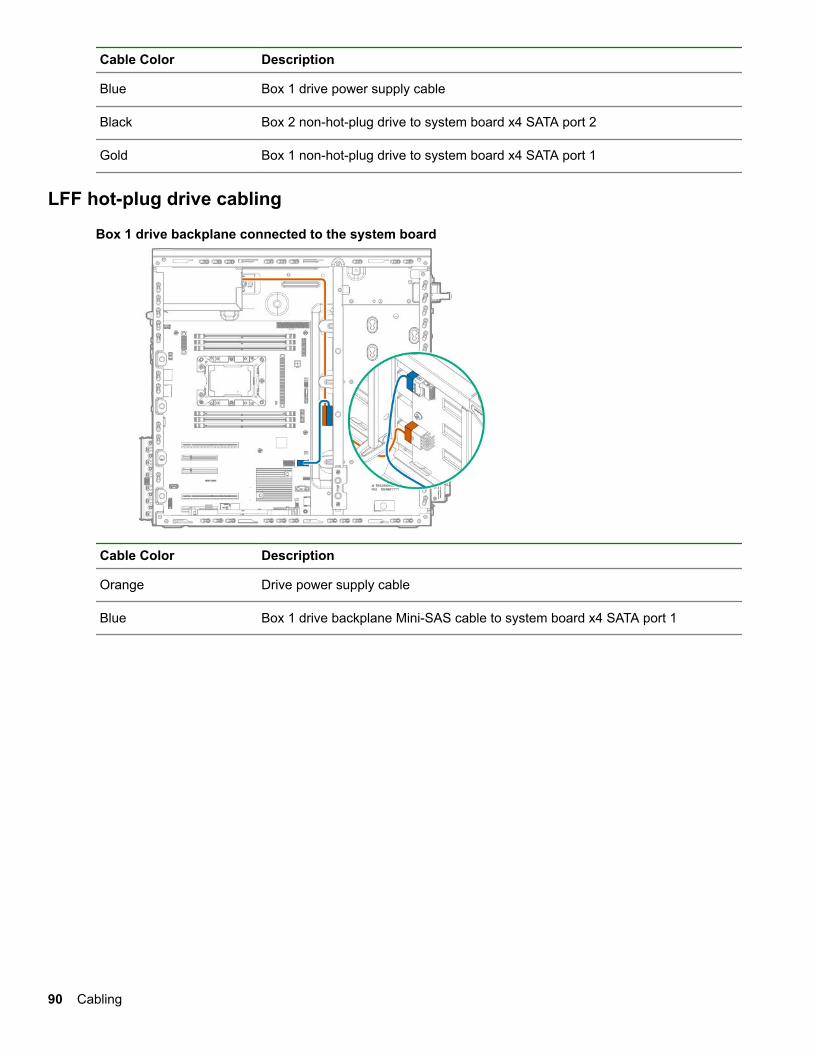
Cable Color Description
Blue Box 1 drive power supply cable
Black Box 2 non-hot-plug drive to system board x4 SATA port 2
Gold Box 1 non-hot-plug drive to system board x4 SATA port 1
LFF hot-plug drive cabling
Box 1 drive backplane connected to the system board
Cable Color Description
Orange Drive power supply cable
Blue Box 1 drive backplane Mini-SAS cable to system board x4 SATA port 1
90 Cabling

Box 2 drive backplane connected the system board
Cable Color Description
Orange Drive power supply cable
Blue Box 2 drive backplane Mini-SAS cable to system board x4 SATA port 2
Box 1 and Box 2 drive backplanes connected to a Smart Array controller
Cable Color Description
Orange Box 2 drive power supply cable
Blue Box 1 drive power supply cable
Table Continued
Cabling 91
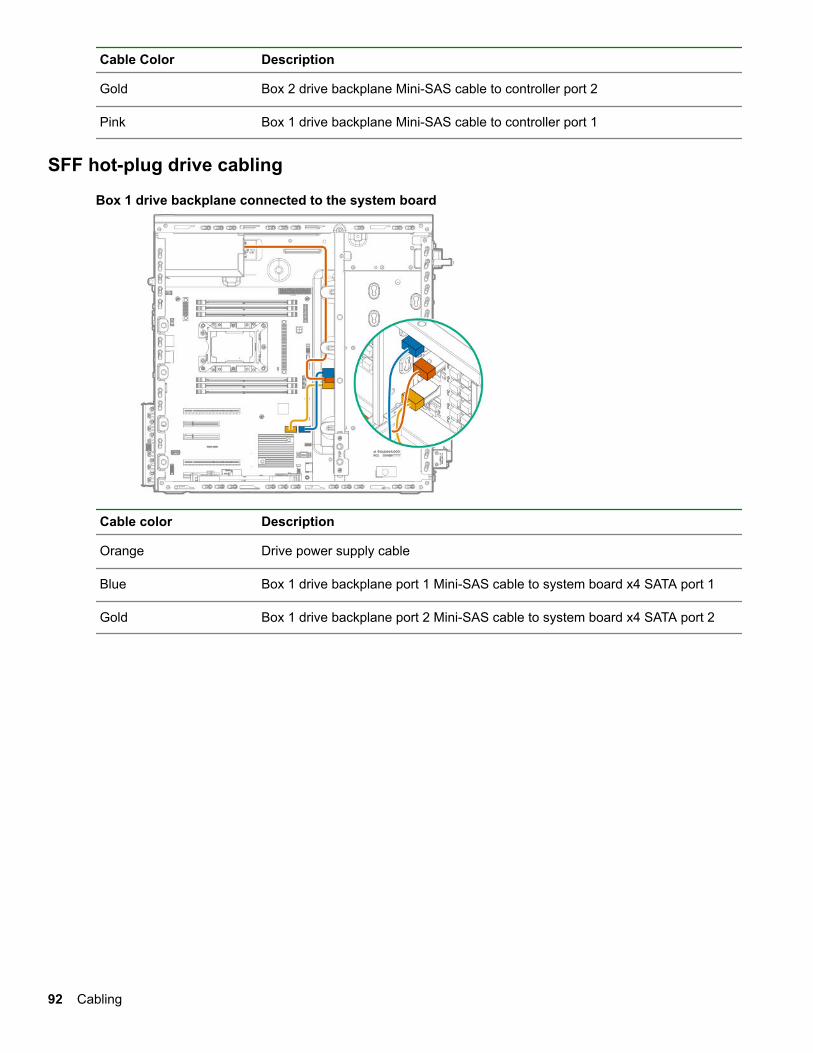
Cable Color Description
Gold Box 2 drive backplane Mini-SAS cable to controller port 2
Pink Box 1 drive backplane Mini-SAS cable to controller port 1
SFF hot-plug drive cabling
Box 1 drive backplane connected to the system board
Cable color Description
Orange Drive power supply cable
Blue Box 1 drive backplane port 1 Mini-SAS cable to system board x4 SATA port 1
Gold Box 1 drive backplane port 2 Mini-SAS cable to system board x4 SATA port 2
92 Cabling

Box 1 drive backplane connected to a Smart Array controller
Item Description
Orange Drive power supply cable
Blue Box 1 drive backplane port 1 Mini-SAS cable to type-p controller port 1
Gold Box 1 drive backplane port 2 Mini-SAS cable to type-p controller port 2
Storage controller cablingSmart Array controller connected to the two 4-bay LFF hot-plug drive cage
Cabling 93

Cable color Description
Orange Box 1 drive backplane Mini-SAS cable to type-pcontroller port 1
Blue Box 2 drive backplane Mini-SAS cable to type-pcontroller port 2
Gold Box 1 drive power supply cable
Pink Box 2 drive power supply cable
Smart Array controllers connected to the 16-bay SFF hot-plug drive cage
Cable color Description
Blue Box 2 drive backplane port 1 Mini-SAS cable to slot 1type-p controller port 1
Gold Box 2 drive backplane port 2 Mini-SAS cable to slot 1type-p controller port 2
Pink Box 1 drive backplane port 1 Mini-SAS cable to slot 2type-p controller port 1
Green Box 1 drive backplane port 2 Mini-SAS cable to slot 2type-p controller port 2
Black Box 1 drive power supply cable
Orange Box 2 drive power supply cable
94 Cabling

Storage controller backup power cabling
Smart Storage Battery cabling
Cabling 95

Optical drive cabling
Cable color Description
Orange Power supply cable
Blue Drive power supply cable
Gold SATA cable
M.2 SSD cabling
96 Cabling
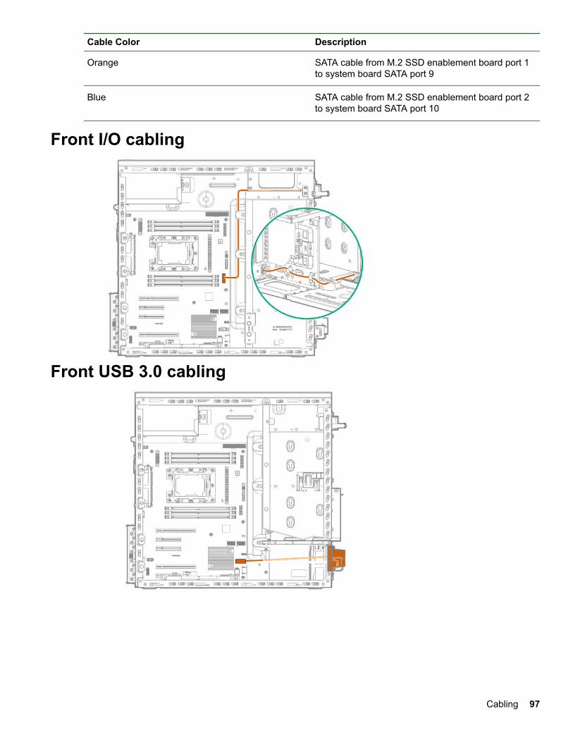
Cable Color Description
Orange SATA cable from M.2 SSD enablement board port 1to system board SATA port 9
Blue SATA cable from M.2 SSD enablement board port 2to system board SATA port 10
Front I/O cabling
Front USB 3.0 cabling
Cabling 97

iLO Service Port cabling
Fan cablingDefault system fan cabling
98 Cabling

Redundant system fan cabling
Cable color Description
Orange System fan cable to fan connector 4
Blue System fan cable to fan connector 3
Default PCI fan cabling
Cabling 99

Redundant PCI fan cabling
Cable color Description
Orange PCI fan cable to fan connector 1
Blue PCI fan cable to fan connector 2
Serial port cabling
100 Cabling

Power supply cabling350W non-hot-plug power supply cabling
Cable Color Description
Orange 8-pin power supply cable to box 2 drive backplane
Blue 8-pin power supply cable to box 1 drive backplane and optical drive
Gold 4-pin power supply cable to system board
Pink 24-pin power supply cable
550W non-hot-plug power supply cabling
Cabling 101

Cable Color Description
Orange 8-pin power supply cable to box 2 drive backplane and optical drive
Blue 8-pin power supply cable to box 1 drive backplane
Gold 4-pin power supply cable to system board
Pink 24-pin power supply cable
Redundant power supply cabling
Cable Color Description
Pink RPSU cable
Blue Box 1 drive backplane power supply cable
Gold 4-pin power supply cable to system board
Orange Box 2 drive backplane and media bay power cable
Green 24-pin power supply cable
102 Cabling
Software and configuration utilitiesServer mode
The software and configuration utilities presented in this section operate in online mode, offline mode, or inboth modes.
Software or configuration utility Server mode
Active Health System on page 103 Online and Offline
HPE iLO 5 on page 104 Online and Offline
HPE Smart Storage Administrator on page 110 Online and Offline
iLO RESTful API on page 106 Online and Offline
Intelligent Provisioning on page 107 Online and Offline
Scripting Toolkit for Windows and Linux on page108
Online
Service Pack for ProLiant on page 112 Online and Offline
Smart Update Manager on page 112 Online and Offline
UEFI System Utilities on page 108 Offline
Product QuickSpecsFor more information about product features, specifications, options, configurations, and compatibility, see theproduct QuickSpecs on the Hewlett Packard Enterprise website (http://www.hpe.com/info/qs).
Active Health System ViewerActive Health System Viewer (AHSV) is an online tool used to read, diagnose, and resolve server issuesquickly using AHS uploaded data. AHSV provides Hewlett Packard Enterprise recommended repair actionsbased on experience and best practices. AHSV provides the ability to:
• Read server configuration information
• View Driver/Firmware inventory
• Review Event Logs
• Respond to Fault Detection Analytics alerts
• Open new and update existing support cases
Active Health SystemThe Active Health System monitors and records changes in the server hardware and system configuration.
The Active Health System provides:
Software and configuration utilities 103

• Continuous health monitoring of over 1600 system parameters
• Logging of all configuration changes
• Consolidated health and service alerts with precise time stamps
• Agentless monitoring that does not affect application performance
For more information about the Active Health System, see the iLO user guide at the following website: http://www.hpe.com/support/ilo-docs.
Active Health System data collectionThe Active Health System does not collect information about your operations, finances, customers,employees, or partners.
Examples of information that is collected:
• Server model and serial number
• Processor model and speed
• Storage capacity and speed
• Memory capacity and speed
• Firmware/BIOS and driver versions and settings
The Active Health System does not parse or change OS data from third-party error event log activities (forexample, content created or passed through the OS).
Active Health System LogThe data collected by the Active Health System is stored in the Active Health System Log. The data is loggedsecurely, isolated from the operating system, and separate from customer data.
When the Active Health System Log is full, new data overwrites the oldest data in the log.
It takes less than 5 minutes to download the Active Health System Log and send it to a support professionalto help you resolve an issue.
When you download and send Active Health System data to Hewlett Packard Enterprise, you agree to havethe data used for analysis, technical resolution, and quality improvements. The data that is collected ismanaged according to the privacy statement, available at http://www.hpe.com/info/privacy.
You can also upload the log to the Active Health System Viewer. For more information, see the Active HealthSystem Viewer documentation at the following website: http://www.hpe.com/support/ahsv-docs.
HPE iLO 5iLO 5 is a remote server management processor embedded on the system boards of HPE ProLiant serversand Synergy compute modules. iLO enables the monitoring and controlling of servers from remote locations.iLO management is a powerful tool that provides multiple ways to configure, update, monitor, and repairservers remotely. iLO (Standard) comes preconfigured on Hewlett Packard Enterprise servers without anadditional cost or license.
Features that enhance server administrator productivity and additional new security features are licensed. Formore information, see the iLO licensing guide at the following website: http://www.hpe.com/support/ilo-docs.
For more information about iLO, see the iLO user guide at the following website: http://www.hpe.com/support/ilo-docs.
104 Software and configuration utilities

iLO FederationiLO Federation enables you to manage multiple servers from one system using the iLO web interface.
When configured for iLO Federation, iLO uses multicast discovery and peer-to-peer communication to enablecommunication between the systems in an iLO Federation group.
When an iLO Federation page loads, a data request is sent from the iLO system running the web interface toits peers, and from those peers to other peers until all data for the selected iLO Federation group is retrieved.
iLO supports the following features:
• Group health status—View server health and model information.
• Group Virtual Media—Connect URL-based media for access by the servers in an iLO Federation group.
• Group power control—Manage the power status of the servers in an iLO Federation group.
• Group power capping—Set dynamic power caps for the servers in an iLO Federation group.
• Group firmware update—Update the firmware of the servers in an iLO Federation group.
• Group license installation—Enter a license key to activate iLO licensed features on the servers in an iLOFederation group.
• Group configuration—Add iLO Federation group memberships for multiple iLO systems.
Any user can view information on iLO Federation pages, but a license is required for using the followingfeatures: Group Virtual Media, Group power control, Group power capping, Group configuration, and Groupfirmware update.
For more information about iLO Federation, see the iLO user guide at the following website: http://www.hpe.com/support/ilo-docs.
iLO Service PortThe Service Port is a USB port with the label iLO on supported ProLiant Gen10 servers and Synergy Gen10compute modules.
To find out if your server model supports this feature, see the server specifications document at the followingwebsite: http://www.hpe.com/info/qs.
When you have physical access to a server, you can use the Service Port to do the following:
• Download the Active Health System Log to a supported USB flash drive.
When you use this feature, the connected USB flash drive is not accessible by the host operating system.
• Connect a client (such as a laptop) with a supported USB to Ethernet adapter to access the iLO webinterface, remote console, CLI, iLO RESTful API, or scripts.
Hewlett Packard Enterprise recommends the HPE USB to Ethernet Adapter (part number Q7Y55A).
Some servers, such as the XL170r, require an adapter to connect a USB to Ethernet adapter to the iLOService Port.
Hewlett Packard Enterprise recommends the HPE Micro USB to USB Adapter (part number 789904-B21).
When you use the iLO Service Port:
• Actions are logged in the iLO Event Log.
• The server UID flashes to indicate the Service Port status.
You can also retrieve the Service Port status by using a REST client and the iLO RESTful API.
Software and configuration utilities 105

• You cannot use the Service Port to boot any device within the server, or the server itself.
• You cannot access the server by connecting to the Service Port.
• You cannot access the connected device from the server.
For more information about the iLO Service Port, see the iLO user guide at the following website: http://www.hpe.com/support/ilo-docs.
iLO RESTful APIiLO includes the iLO RESTful API, which is Redfish API conformant. The iLO RESTful API is a managementinterface that server management tools can use to perform configuration, inventory, and monitoring tasks bysending basic HTTPS operations (GET, PUT, POST, DELETE, and PATCH) to the iLO web server.
To learn more about the iLO RESTful API, see the Hewlett Packard Enterprise website (http://www.hpe.com/info/restfulinterface/docs).
For specific information about automating tasks using the iLO RESTful API, see libraries and sample code at http://www.hpe.com/info/redfish.
RESTful Interface ToolThe RESTful Interface Tool (iLOREST) is a scripting tool that allows you to automate HPE servermanagement tasks. It provides a set of simplified commands that take advantage of the iLO RESTful API. Youcan install the tool on your computer for remote use or install it locally on a server with a Windows or LinuxOperating System. The RESTful Interface Tool offers an interactive mode, a scriptable mode, and a file-basedmode similar to CONREP to help decrease automation times.
For more information, see the following website: http://www.hpe.com/info/resttool.
iLO Amplifier PackThe iLO Amplifier Pack is an advanced server inventory, firmware and driver update solution that enablesrapid discovery, detailed inventory reporting, firmware, and driver updates by leveraging iLO advancedfunctionality. The iLO Amplifier Pack performs rapid server discovery and inventory for thousands ofsupported servers for the purpose of updating firmware and drivers at scale.
For more information about iLO Amplifier Pack, see the iLO Amplifier Pack User Guide at the followingwebsite: http://www.hpe.com/support/ilo-ap-ug-en.
Integrated Management LogThe IML records hundreds of events and stores them in an easy-to-view form. The IML timestamps eachevent with one-minute granularity.
You can view recorded events in the IML in several ways, including the following:
• From within HPE SIM
• From within the UEFI System Utilities
• From within the Embedded UEFI shell
• From within the iLO web interface
106 Software and configuration utilities

Intelligent ProvisioningIntelligent Provisioning is a single-server deployment tool embedded in ProLiant servers and HPE Synergycompute modules. Intelligent Provisioning simplifies server setup, providing a reliable and consistent way todeploy servers.
Intelligent Provisioning prepares the system for installing original, licensed vendor media and Hewlett PackardEnterprise-branded versions of OS software. Intelligent Provisioning also prepares the system to integrateoptimized server support software from the Service Pack for ProLiant (SPP). SPP is a comprehensivesystems software and firmware solution for ProLiant servers, server blades, their enclosures, and HPESynergy compute modules. These components are preloaded with a basic set of firmware and OScomponents that are installed along with Intelligent Provisioning.
IMPORTANT: HPE ProLiant XL servers do not support operating system installation with IntelligentProvisioning, but they do support the maintenance features. For more information, see "PerformingMaintenance" in the Intelligent Provisioning User Guide and online help.
After the server is running, you can update the firmware to install additional components. You can also updateany components that have been outdated since the server was manufactured.
To access Intelligent Provisioning:
• Press F10 from the POST screen.
• From the iLO web interface using Always On. Always On allows you to access Intelligent Provisioningwithout rebooting your server.
Intelligent Provisioning operationIntelligent Provisioning includes the following components:
• Critical boot drivers
• Active Health System (AHS)
• Erase Utility
• Deployment Settings
IMPORTANT:
• Although your server is pre-loaded with firmware and drivers, you should update the firmware uponinitial setup to ensure you have the latest versions. Also, downloading and updating the latestversion of Intelligent Provisioning ensures the latest supported features are available.
• For ProLiant servers, firmware is updated using the Intelligent Provisioning Firmware Update utility.
• Do not update firmware if the version you are currently running is required for compatibility.
NOTE: Intelligent Provisioning does not function within multihomed configurations. A multihomed host is onethat is connected to two or more networks or has two or more IP addresses.
Intelligent Provisioning provides installation help for the following operating systems:
• Microsoft Windows Server
• Red Hat Enterprise Linux
Software and configuration utilities 107

• SUSE Linux Enterprise Server
• VMware ESXi/vSphere Custom Image
Not all versions of an OS are supported. For information about specific versions of a supported operatingsystem, see the OS Support Matrix on the Hewlett Packard Enterprise website (http://www.hpe.com/info/ossupport).
Management SecurityHPE ProLiant Gen10 servers are built with some of the industry's most advanced security capabilities, out ofthe box, with a foundation of secure embedded management applications and firmware. The managementsecurity provided by HPE embedded management products enables secure support of modern workloads,protecting your components from unauthorized access and unapproved use. The range of embeddedmanagement and optional software and firmware available with the iLO Advanced and iLO AdvancedPremium Security Edition licenses provides security features that help ensure protection, detection, andrecovery from advanced cyber-attacks. For more information, see the HPE Gen10 Server Security ReferenceGuide on the Hewlett Packard Enterprise Information Library at http://www.hpe.com/support/gen10-security-ref-en.
For information about the iLO Advanced Premium Security Edition license, see http://www.hpe.com/servers/ilopremium.
Scripting Toolkit for Windows and LinuxThe STK for Windows and Linux is a server deployment product that delivers an unattended automatedinstallation for high-volume server deployments. The STK is designed to support ProLiant servers. The toolkitincludes a modular set of utilities and important documentation that describes how to apply these tools tobuild an automated server deployment process.
The STK provides a flexible way to create standard server configuration scripts. These scripts are used toautomate many of the manual steps in the server configuration process. This automated server configurationprocess cuts time from each deployment, making it possible to scale rapid, high-volume server deployments.
For more information or to download the STK, see the Hewlett Packard Enterprise website.
UEFI System UtilitiesThe UEFI System Utilities is embedded in the system ROM. Its features enable you to perform a wide rangeof configuration activities, including:
• Configuring system devices and installed options.
• Enabling and disabling system features.
• Displaying system information.
• Selecting the primary boot controller or partition.
• Configuring memory options.
• Launching other preboot environments.
HPE servers with UEFI can provide:
• Support for boot partitions larger than 2.2 TB. Such configurations could previously only be used for bootdrives when using RAID solutions.
• Secure Boot that enables the system firmware, option card firmware, operating systems, and softwarecollaborate to enhance platform security.
108 Software and configuration utilities
• UEFI Graphical User Interface (GUI)
• An Embedded UEFI Shell that provides a preboot environment for running scripts and tools.
• Boot support for option cards that only support a UEFI option ROM.
Selecting the boot modeThis server provides two Boot Mode configurations: UEFI Mode and Legacy BIOS Mode. Certain bootoptions require that you select a specific boot mode. By default, the boot mode is set to UEFI Mode. Thesystem must boot in UEFI Mode to use certain options, including:
• Secure Boot, UEFI Optimized Boot, Generic USB Boot, IPv6 PXE Boot, iSCSI Boot, and Boot from URL
• Fibre Channel/FCoE Scan Policy
NOTE: The boot mode you use must match the operating system installation. If not, changing the boot modecan impact the ability of the server to boot to the installed operating system.
Prerequisite
When booting to UEFI Mode, leave UEFI Optimized Boot enabled.
Procedure
1. From the System Utilities screen, select System Configuration > BIOS/Platform Configuration(RBSU) > Boot Options > Boot Mode.
2. Select a setting.
• UEFI Mode (default)—Configures the system to boot to a UEFI compatible operating system.
• Legacy BIOS Mode—Configures the system to boot to a traditional operating system in Legacy BIOScompatibility mode.
3. Save your setting.
4. Reboot the server.
Secure BootSecure Boot is a server security feature that is implemented in the BIOS and does not require specialhardware. Secure Boot ensures that each component launched during the boot process is digitally signed andthat the signature is validated against a set of trusted certificates embedded in the UEFI BIOS. Secure Bootvalidates the software identity of the following components in the boot process:
• UEFI drivers loaded from PCIe cards
• UEFI drivers loaded from mass storage devices
• Preboot UEFI Shell applications
• OS UEFI boot loaders
When Secure Boot is enabled:
Software and configuration utilities 109

• Firmware components and operating systems with boot loaders must have an appropriate digital signatureto execute during the boot process.
• Operating systems must support Secure Boot and have an EFI boot loader signed with one of theauthorized keys to boot. For more information about supported operating systems, see http://www.hpe.com/servers/ossupport.
You can customize the certificates embedded in the UEFI BIOS by adding or removing your own certificates,either from a management console directly attached to the server, or by remotely connecting to the serverusing the iLO Remote Console.
You can configure Secure Boot:
• Using the System Utilities options described in the following sections.
• Using the iLO RESTful API to clear and restore certificates. For more information, see the Hewlett PackardEnterprise website (http://www.hpe.com/info/redfish).
• Using the secboot command in the Embedded UEFI Shell to display Secure Boot databases, keys, andsecurity reports.
Launching the Embedded UEFI ShellUse the Embedded UEFI Shell option to launch the Embedded UEFI Shell. The Embedded UEFI Shell is apreboot command-line environment for scripting and running UEFI applications, including UEFI boot loaders.The Shell also provides CLI-based commands you can use to obtain system information, and to configure andupdate the system BIOS.
Prerequisites
Embedded UEFI Shell is set to Enabled.
Procedure
1. From the System Utilities screen, select Embedded Applications > Embedded UEFI Shell.
The Embedded UEFI Shell screen appears.
2. Press any key to acknowledge that you are physically present.
This step ensures that certain features, such as disabling Secure Boot or managing the Secure Bootcertificates using third-party UEFI tools, are not restricted.
3. If an administrator password is set, enter it at the prompt and press Enter.
The Shell> prompt appears.
4. Enter the commands required to complete your task.
5. Enter the exit command to exit the Shell.
HPE Smart Storage AdministratorHPE SSA is the main tool for configuring arrays on HPE Smart Array SR controllers. It exists in three interfaceformats: the HPE SSA GUI, the HPE SSA CLI, and HPE SSA Scripting. All formats provide support forconfiguration tasks. Some of the advanced tasks are available in only one format.
The diagnostic features in HPE SSA are also available in the standalone software HPE Smart StorageAdministrator Diagnostics Utility CLI.
110 Software and configuration utilities

During the initial provisioning of the server or compute module, an array is required to be configured beforethe operating system can be installed. You can configure the array using SSA.
HPE SSA is accessible both offline (either through HPE Intelligent Provisioning or as a standalone bootableISO image) and online:
• Accessing HPE SSA in the offline environment
IMPORTANT: If you are updating an existing server in an offline environment, obtain the latestversion of HPE SSA through Service Pack for ProLiant before performing configuration procedures.
Using one of multiple methods, you can run HPE SSA before launching the host operating system. Inoffline mode, users can configure or maintain detected and supported devices, such as optional SmartArray controllers and integrated Smart Array controllers. Some HPE SSA features are only available in theoffline environment, such as setting the boot controller and boot volume.
• Accessing HPE SSA in the online environment
This method requires an administrator to download the HPE SSA executables and install them. You canrun HPE SSA online after launching the host operating system.
For more information, see HPE Smart Array SR Gen10 Configuration Guide at the Hewlett PackardEnterprise website.
USB supportHewlett Packard Enterprise Gen10 servers support all USB operating speeds depending on the device that isconnected to the server.
External USB functionalityHewlett Packard Enterprise provides external USB support to enable local connection of USB devices forserver administration, configuration, and diagnostic procedures.
For additional security, external USB functionality can be disabled through USB options in UEFI SystemUtilities.
Redundant ROM supportThe server enables you to upgrade or configure the ROM safely with redundant ROM support. The server hasa single ROM that acts as two separate ROM images. In the standard implementation, one side of the ROMcontains the current ROM program version, while the other side of the ROM contains a backup version.
NOTE: The server ships with the same version programmed on each side of the ROM.
Safety and security benefitsWhen you flash the system ROM, the flashing mechanism writes over the backup ROM and saves the currentROM as a backup, enabling you to switch easily to the alternate ROM version if the new ROM becomescorrupted for any reason. This feature protects the existing ROM version, even if you experience a powerfailure while flashing the ROM.
Keeping the system currentUpdating firmware or system ROM
To update firmware or system ROM, use one of the following methods:
Software and configuration utilities 111
• The Firmware Update option in the System Utilities.
• The fwupdate command in the Embedded UEFI Shell.
• Service Pack for ProLiant (SPP)
• HPE online flash components
• Moonshot Component Pack
Service Pack for ProLiantSPP is a systems software and firmware solution delivered as a single ISO file download. This solution usesSUM as the deployment tool and is tested and supports HPE ProLiant, HPE BladeSystem, HPE Synergy, andHPE Apollo servers and infrastructure.
SPP, along with SUM and iSUT, provides Smart Update system maintenance tools that systematically updateHPE ProLiant, HPE BladeSystem, HPE Synergy, and HPE Apollo servers and infrastructure.
SPP can be used in an online mode on a server running Windows, Linux, or VMware vSphere ESXi, or in anoffline mode where the server is booted to an operating system included in the ISO file.
The preferred method for downloading an SPP is using the SPP Custom Download at www.hpe.com/servers/custom.
The SPP is also available for download from the SPP download page at https://www.hpe.com/servers/spp/download.
Smart Update ManagerSUM is an innovative tool for maintaining and updating the firmware, drivers, and system software of HPEProLiant, HPE BladeSystem, HPE Synergy, and HPE Apollo servers, infrastructure, and associated options.
SUM identifies associated nodes you can update at the same time to avoid interdependency issues.
Key features of SUM include:
• Discovery engine that finds installed versions of hardware, firmware, and software on nodes.
• SUM deploys updates in the correct order and ensures that all dependencies are met before deploying anupdate.
• Interdependency checking.
• Automatic and step-by-step Localhost Guided Update process.
• Web browser-based user interface.
• Ability to create custom baselines and ISOs.
• Support for iLO Repository (Gen10 iLO 5 nodes only).
• Simultaneous firmware and software deployment for multiple remote nodes.
• Local offline firmware deployments with SPP deliverables.
• Extensive logging in all modes.
NOTE: SUM does not support third-party controllers, including flashing hard drives behind the controllers.
112 Software and configuration utilities

Integrated Smart Update ToolsIntegrated Smart Update Tools (iSUT) is a software utility used with iLO 4, iLO 5, iLO Amplifier Pack, HPEOneView, Service Pack for ProLiant (SPP), and Smart Update Manager (SUM) to stage, install, and activatefirmware and driver updates.
• iSUT: Polls iLO to check for requests from HPE OneView, SUM, or iLO Amplifier Pack for updates throughthe management network and orchestrates staging, deploying, and activating updates. You can adjust thepolling interval by issuing the appropriate command-line option provided by iSUT. Performs inventory ontarget servers, stages deployment, deploys updates, and then reboots the servers.
• iLO 5 with integrated Smart Update (Gen10 servers only): Performs iLO Repository-based updates bydownloading the components from iLO Repository when iLO Installation Queue has the components whichcan be updated by iSUT.
• iLO Amplifier Pack: Displays available updates for servers. Communicates with iSUT (or SUT 1.x) toinitiate updates using the iLO Redfish interface. iSUT reports the status of updates to iLO Amplifier Packvia iLO Restful Interface.
• HPE OneView: Displays available updates for servers. Communicates with iSUT (or SUT 1.x) to initiateupdates, reports the status on the Firmware section of the Server Profile page of HPE OneView. HPEOneView provides automated compliance reporting in the dashboard.
• SPP: A comprehensive systems software and firmware update solution, which is delivered as a single ISOimage.
• SUM: A tool for firmware and driver maintenance for HPE ProLiant servers and associated options.
NOTE: SUM, iLO Amplifier Pack, and HPE OneView should not manage the same nodes.
Updating firmware from the System UtilitiesUse the Firmware Updates option to update firmware components in the system, including the system BIOS,NICs, and storage cards.
Procedure
1. Access the System ROM Flash Binary component for your server from the Hewlett Packard EnterpriseSupport Center.
2. Copy the binary file to a USB media or iLO virtual media.
3. Attach the media to the server.
4. Launch the System Utilities, and select Embedded Applications > Firmware Update.
5. Select a device.
The Firmware Updates screen lists details about your selected device, including the current firmwareversion in use.
6. Select Select Firmware File.
7. Select the flash file in the File Explorer list.
The firmware file is loaded and the Firmware Updates screen lists details of the file in the Selectedfirmware file field.
8. Select Image Description, and then select a firmware image.
Software and configuration utilities 113

A device can have multiple firmware images.
9. Select Start firmware update.
Updating the firmware from the UEFI Embedded Shell
Procedure
1. Access the System ROM Flash Binary component for your server from the Hewlett Packard EnterpriseSupport Center (http://www.hpe.com/support/hpesc).
2. Copy the binary file to a USB media or iLO virtual media.
3. Attach the media to the server.
4. Boot to the UEFI Embedded Shell.
5. To obtain the assigned file system volume for the USB key, enter map –r.
6. Change to the file system that contains the System ROM Flash Binary component for your server. Enterone of the fsx file systems available, such as fs0: or fs1:, and press Enter.
7. Use the cd command to change from the current directory to the directory that contains the binary file.
8. Flash the system ROM by entering fwupdate –d BIOS -f filename.
9. Reboot the server. A reboot is required after the firmware update in order for the updates to take effect andfor hardware stability to be maintained.
Online Flash componentsThis component provides updated system firmware that can be installed directly on supported operatingsystems. Additionally, when used in conjunction with SUM, this Smart Component allows the user to updatefirmware on remote servers from a central location. This remote deployment capability eliminates the need forthe user to be physically present at the server to perform a firmware update.
Drivers
IMPORTANT: Always perform a backup before installing or updating device drivers.
Update drivers using any of the following Smart Update Solutions:
• Download the latest Service Pack for ProLiant (includes Smart Update Manager)
• Create a custom SPP download
• Download Smart Update Manager for Linux
• Download specific drivers
To locate the drivers for a server, go to the Hewlett Packard Enterprise Support Center website, andthen search for the product name/number.
Software and firmwareUpdate software and firmware before using the server for the first time, unless any installed software orcomponents require an older version.
For system software and firmware updates, use one of the following sources:
114 Software and configuration utilities

• Download the SPP from the Hewlett Packard Enterprise website (http://www.hpe.com/servers/spp/download).
• Download individual drivers, firmware, or other system software components from the server product pagein the Hewlett Packard Enterprise Support Center website (http://www.hpe.com/support/hpesc).
Operating system version supportFor information about specific versions of a supported operating system, refer to the operating systemsupport matrix.
HPE Pointnext PortfolioHPE Pointnext delivers confidence, reduces risk, and helps customers realize agility and stability. HewlettPackard Enterprise helps customers succeed through Hybrid IT by simplifying and enriching the on-premiseexperience, informed by public cloud qualities and attributes.
Operational Support Services enable you to choose the right service level, length of coverage, and responsetime to fit your business needs. For more information, see the Hewlett Packard Enterprise website:
https://www.hpe.com/us/en/services/operational.html
Utilize the Advisory and Transformation Services in the following areas:
• Private or hybrid cloud computing
• Big data and mobility requirements
• Improving data center infrastructure
• Better use of server, storage, and networking technology
For more information, see the Hewlett Packard Enterprise website:
http://www.hpe.com/services/consulting
Proactive notifications30 to 60 days in advance, Hewlett Packard Enterprise sends notifications to subscribed customers onupcoming:
• Hardware, firmware, and software changes
• Bulletins
• Patches
• Security alerts
You can subscribe to proactive notifications on the Hewlett Packard Enterprise website.
Software and configuration utilities 115

System battery replacementSystem battery information
The server contains an internal lithium manganese dioxide, a vanadium pentoxide, or an alkaline battery thatprovides power to the real-time clock. If this battery is not properly handled, a risk of the fire and burns exists.To reduce the risk of personal injury:
• Do not attempt to recharge the battery.
• Do not expose the battery to temperatures higher than 60°C (140°F).
• Do not disassemble, crush, puncture, short external contacts, or dispose the battery in fire or water.
• If the server no longer automatically displays the correct date and time, then replace the battery thatprovides power to the real-time clock. Under normal use, battery life is 5 to 10 years.
Removing and replacing the system batteryProcedure
1. Power down the server on page 31.
2. Remove all power:
a. Disconnect each power cord from the power source.
b. Disconnect each power cord from the server.
3. Do one of the following:
• Server in rack mode: Remove the server from the rack on page 31.
• Server in tower mode: Place the server on its side with the access panel facing up.
4. Remove the access panel on page 33.
5. Remove the PCI air baffle on page 36.
6. Remove the system air baffle on page 38.
7. Replace the system battery.
8. Install the system air baffle on page 38.
9. Install the PCI air baffle on page 37.
10. Install the access panel on page 34.
11. Do one of the following:
• Server in rack mode: Install the server into the rack on page 49.
• Server in tower mode: Return the server to an upright position.
12. Connect each power cord to the server.
116 System battery replacement
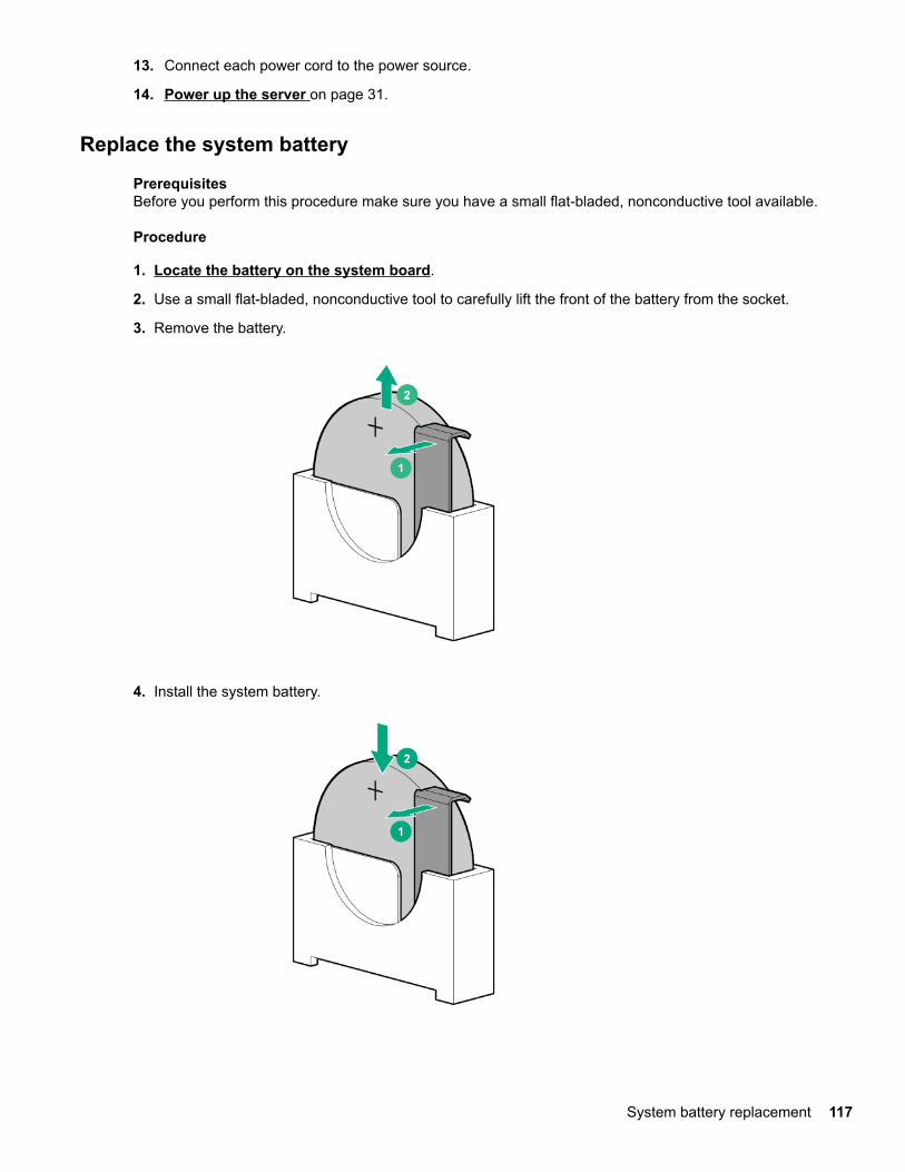
13. Connect each power cord to the power source.
14. Power up the server on page 31.
Replace the system battery
PrerequisitesBefore you perform this procedure make sure you have a small flat-bladed, nonconductive tool available.
Procedure
1. Locate the battery on the system board.
2. Use a small flat-bladed, nonconductive tool to carefully lift the front of the battery from the socket.
3. Remove the battery.
4. Install the system battery.
System battery replacement 117

For more information about battery replacement or proper disposal, contact an authorized reseller or anauthorized service provider.
118 System battery replacement

TroubleshootingNMI functionality
An NMI crash dump enables administrators to create crash dump files when a system is hung and notresponding to traditional debugging methods.
An analysis of the crash dump log is an essential part of diagnosing reliability problems, such as hangingoperating systems, device drivers, and applications. Many crashes freeze a system, and the only availableaction for administrators is to cycle the system power. Resetting the system erases any information that couldsupport problem analysis, but the NMI feature preserves that information by performing a memory dumpbefore a hard reset.
To force the OS to invoke the NMI handler and generate a crash dump log, the administrator can use the iLOVirtual NMI feature.
Troubleshooting resourcesTroubleshooting resources are available for HPE Gen10 server products in the following documents:
• Troubleshooting Guide for HPE ProLiant Gen10 servers provides procedures for resolving commonproblems and comprehensive courses of action for fault isolation and identification, issue resolution, andsoftware maintenance.
• Error Message Guide for HPE ProLiant Gen10 servers and HPE Synergy provides a list of error messagesand information to assist with interpreting and resolving error messages.
• Integrated Management Log Messages and Troubleshooting Guide for HPE ProLiant Gen10 and HPESynergy provides IML messages and associated troubleshooting information to resolve critical andcautionary IML events.
To access the troubleshooting resources, see the Hewlett Packard Enterprise Information Library (http://www.hpe.com/info/gen10-troubleshooting).
Troubleshooting 119
SpecificationsEnvironmental specifications
Specification Value
Temperature range1 —
Operating 10°C to 35°C (41°F to 95°F)
Nonoperating -30°C to 60°C (-22°F to 140°F)
Relative humidity (noncondensing) —
Operating 8% to 90%
28°C (82.4°F), maximum wet bulb temperature
Nonoperating 5% to 95%
38.7°C (101.7°F), maximum wet bulb temperature
1 All temperature ratings shown are for sea level. An altitude derating of 1.0°C per 305 m (1.8°F per 1000 ft) to 3050 m(10,000 ft) is applicable. No direct sunlight allowed. Maximum rate of change is 20°C per hour (36°F per hour). The upperlimit and rate of change might be limited by the type and number of options installed.
For certain approved hardware configurations, the supported system inlet temperature range is extended:
• 5°C to 10°C (41°F to 50°F) and 35°C to 40°C (95°F to 104°F) at sea level with an altitude derating of 1.0°Cper every 175 m (1.8°F per every 574 ft) above 900 m (2953 ft) to a maximum of 3050 m (10,000 ft)
• Redundant fans are required when the ambient temperature reaches 35°C (95°F) to 40°C (104°F).
The approved hardware configurations for this system are listed on the Hewlett Packard Enterprise website(http://www.hpe.com/servers/ASHRAE).
Mechanical specificationsDimension (with feet/bezel) Value
Height 44.00 cm (17.32 in)
Depth 48.05 cm (18.92 in)
Width 19.50 cm (7.68 in)
Weight (approximate)
Minimum (one drive, power supply, and processorinstalled)
13.5 kg (29.82 lb)
Maximum (all drives, power supplies, and processorsinstalled)
25.0 kg (55.00 lb)
Power supply specificationsDepending on the installed options and/or the regional location where the server was purchased, the server isconfigured with one of the following power supplies:
120 Specifications

• ATX 350W non-hot-plug power supply on page 121
• ATX 550W non-hot-plug power supply on page 121
• HPE 800W Flex Slot Platinum Hot-plug Low Halogen Power Supply on page 122
CAUTION: Check the system and power supply input ratings before powering up the server.
ATX 350W non-hot-plug power supplySpecification Value
Input requirements
Rated input voltage 100 VAC to 240 VAC
Rated input frequency 50 Hz to 60 Hz
Rated input current 4.5 A at 100 VAC
1.9 A at 240 VAC
Maximum rated input power 437 W at 100 VAC
416 W at 240 VAC
BTUs per hour 1491 at 100 VAC
1419 at 240 VAC
Power supply output
Rated steady-state power 350 W at 100VAC to 240VAC
Maximum peak power 385 W at 100VAC to 240VAC
ATX 550W non-hot-plug power supplySpecification Value
Input requirements
Rated input voltage 100 VAC to 240 VAC
Rated input frequency 50 Hz to 60 Hz
Rated input current 6.4 A at 100 VAC
2.62 A at 240 VAC
Maximum rated input power 634 W at 100 VAC
613 W at 240 VAC
BTUs per hour 1876 at 100 VAC
1876 at 240 VAC
Table Continued
Specifications 121

Specification Value
Power supply output
Rated steady-state power 550 W at 100VAC to 240VAC
Maximum peak power 575 W at 100VAC to 240VAC
HPE 800W Flex Slot Platinum Hot-plug Low Halogen Power SupplySpecification Value
Input requirements —
Rated input voltage 100 VAC to 127 VAC
200 VAC to 240 VAC
240 VDC for China only
Rated input frequency 50 Hz to 60 Hz
Not applicable to 240 VDC
Rated input current 9.1 A at 100 VAC
4.4 A at 200 VAC
3.6 A at 240 VDC for China only
Maximum rated input power 899 W at 100 VAC
867 W at 200 VAC
864 W at 240 VDC for China only
BTUs per hour 3067 at 100 VAC
2958 at 200 VAC
2949 at 240 VAC for China only
Power supply output —
Rated steady-state power 800 W at 100 VAC to 127 VAC input
800 W at 100 VAC to 240 VAC input
800 W at 240 VDC input for China only
Maximum peak power 800 W at 100 VAC to 127 VAC input
800 W at 100 VAC to 240 VAC input
800 W at 240 VDC input for China only
122 Specifications

Safety, warranty, and regulatory informationRegulatory information
To view the regulatory information for your product, view the Safety and Compliance Information for Server,Storage, Power, Networking, and Rack Products, available at the Hewlett Packard Enterprise Support Center:
www.hpe.com/support/Safety-Compliance-EnterpriseProducts
Additional regulatory information
Hewlett Packard Enterprise is committed to providing our customers with information about the chemicalsubstances in our products as needed to comply with legal requirements such as REACH (Regulation EC No1907/2006 of the European Parliament and the Council). A chemical information report for this product can befound at:
www.hpe.com/info/reach
For Hewlett Packard Enterprise product environmental and safety information and compliance data, includingRoHS and REACH, see:
www.hpe.com/info/ecodata
For Hewlett Packard Enterprise environmental information, including company programs, product recycling,and energy efficiency, see:
www.hpe.com/info/environment
Local representative informationLocal representative information Russian
Russia:
Belarus:
Kazakhstan:
Local representative information Kazakh
Russia:
Safety, warranty, and regulatory information 123
Belarus:
Kazakhstan:
Turkey RoHS material content declaration
Ukraine RoHS material content declaration
Warranty informationTo view the warranty information for your product, see the links provided below:
HPE ProLiant and IA-32 Servers and Optionswww.hpe.com/support/ProLiantServers-Warranties
HPE Enterprise and Cloudline Serverswww.hpe.com/support/EnterpriseServers-Warranties
HPE Storage Productswww.hpe.com/support/Storage-Warranties
HPE Networking Productswww.hpe.com/support/Networking-Warranties
124 Safety, warranty, and regulatory information

WebsitesGeneral websitesHewlett Packard Enterprise Information Library
www.hpe.com/info/EILSubscription Service/Support Alerts
www.hpe.com/support/e-updates
Single Point of Connectivity Knowledge (SPOCK) Storage compatibility matrixwww.hpe.com/storage/spock
Storage white papers and analyst reportswww.hpe.com/storage/whitepapers
For additional general support websites, see Support and other resources.
Product websitesProduct QuickSpecs
http://www.hpe.com/servers/ml110-gen10
HPE ProLiant ML110 Gen10 support page
http://www.hpe.com/support/ml110gen10
HPE ProLiant ML110 Gen10 documents
http://www.hpe.com/info/ml110gen10-docs
Websites 125

Support and other resourcesAccessing Hewlett Packard Enterprise Support
• For live assistance, go to the Contact Hewlett Packard Enterprise Worldwide website:
http://www.hpe.com/assistance
• To access documentation and support services, go to the Hewlett Packard Enterprise Support Centerwebsite:
http://www.hpe.com/support/hpesc
Information to collect
• Technical support registration number (if applicable)
• Product name, model or version, and serial number
• Operating system name and version
• Firmware version
• Error messages
• Product-specific reports and logs
• Add-on products or components
• Third-party products or components
ClearCARE technical supportSupport for ClearOS and ClearVM is not provided by Hewlett Packard Enterprise. Support for ClearOS andClearVM is purchased and delivered by ClearCenter. You can purchase single support incidents by submittinga support ticket to ClearCenter, or you can purchase a Bronze, Silver, Gold, or Platinum ClearCAREsubscription. For more information, go to the ClearOS website:
https://www.clearos.com/
Several levels of professional technical support are available to licensed users. For more information, go tothe ClearCARE support website:
https://www.clearos.com/products/support/clearcare-overview
Accessing updates• Some software products provide a mechanism for accessing software updates through the product
interface. Review your product documentation to identify the recommended software update method.
• To download product updates:
Hewlett Packard Enterprise Support Centerwww.hpe.com/support/hpesc
Hewlett Packard Enterprise Support Center: Software downloadswww.hpe.com/support/downloads
126 Support and other resources

Software Depotwww.hpe.com/support/softwaredepot
• To subscribe to eNewsletters and alerts:
www.hpe.com/support/e-updates
• To view and update your entitlements, and to link your contracts and warranties with your profile, go to theHewlett Packard Enterprise Support Center More Information on Access to Support Materials page:
www.hpe.com/support/AccessToSupportMaterials
IMPORTANT: Access to some updates might require product entitlement when accessed through theHewlett Packard Enterprise Support Center. You must have an HPE Passport set up with relevantentitlements.
Customer self repairHewlett Packard Enterprise customer self repair (CSR) programs allow you to repair your product. If a CSRpart needs to be replaced, it will be shipped directly to you so that you can install it at your convenience.Some parts do not qualify for CSR. Your Hewlett Packard Enterprise authorized service provider willdetermine whether a repair can be accomplished by CSR.
For more information about CSR, contact your local service provider or go to the CSR website:
http://www.hpe.com/support/selfrepair
Remote supportRemote support is available with supported devices as part of your warranty or contractual supportagreement. It provides intelligent event diagnosis, and automatic, secure submission of hardware eventnotifications to Hewlett Packard Enterprise, which will initiate a fast and accurate resolution based on yourproduct's service level. Hewlett Packard Enterprise strongly recommends that you register your device forremote support.
If your product includes additional remote support details, use search to locate that information.
Remote support and Proactive Care informationHPE Get Connected
www.hpe.com/services/getconnectedHPE Proactive Care services
www.hpe.com/services/proactivecareHPE Proactive Care service: Supported products list
www.hpe.com/services/proactivecaresupportedproductsHPE Proactive Care advanced service: Supported products list
www.hpe.com/services/proactivecareadvancedsupportedproducts
Proactive Care customer informationProactive Care central
www.hpe.com/services/proactivecarecentralProactive Care service activation
www.hpe.com/services/proactivecarecentralgetstarted
Support and other resources 127

Documentation feedbackHewlett Packard Enterprise is committed to providing documentation that meets your needs. To help usimprove the documentation, send any errors, suggestions, or comments to Documentation Feedback([email protected]). When submitting your feedback, include the document title, part number, edition,and publication date located on the front cover of the document. For online help content, include the productname, product version, help edition, and publication date located on the legal notices page.
128 Support and other resources

Acronyms and abbreviations3DS TSV
three-dimensional stacked through-silicon via (integrated circuit packaging technology)
ADDDC
adaptive double device data correction
AHCI
advanced host controller interface
AHS
Active Health System
AHSV
Active Health System Viewer
API
application program interface
ASHRAE
American Society of Heating, Refrigerating and Air-Conditioning Engineers
CAS
column address strobe
CSA
Canadian Standards Association
CSR
customer self repair
DDR4
double data rate-4
GPU
graphics processing unit
HPE SSA
HPE Smart Storage Administrator
IEC
International Electrotechnical Commission
iLO
Integrated Lights-Out
IML
Integrated Management Log
ISO
International Organization for Standardization
Acronyms and abbreviations 129

iSUT
Integrated Smart Update Tools
LFF
large form factor
LRDIMM
load reduced dual in-line memory module
NMI
nonmaskable interrupt
PCA
printed circuit assembly
PCIe
Peripheral Component Interconnect Express
PDU
power distribution unit
POST
Power-On Self-Test
PXE
Preboot eXecution Environment
RAS
Reliability, Accessibility, Serviceability
RBSU
ROM-Based Setup Utility
RDIMM
registered dual in-line memory module
REST
representational state transfer
RoHS
Restriction of Hazardous Substances
RPS
redundant power supply
SD
secure digital
SAS
serial attached SCSI
SATA
serial ATA
130 Acronyms and abbreviations

SFF
small form factor
STK
scripting toolkit
SPP
Service Pack for ProLiant
SSD
solid state drive
SUM
Smart Update Manager
TMRA
recommended ambient operating temperature
TPM
Trusted Platform Module
UDIMM
unregistered dual in-line memory module
UEFI
Unified Extensible Firmware Interface
UID
unit identification
Acronyms and abbreviations 131