hopper design.pdf
31
5.0 HOPPER DESIGN 5.1 Bulk solid handling Measuring the flow properties of bulk solids and h ow to use t his i nformation fo the design of storage vessel. Definitions: Bin: Any upright container for storing bulk solids. Silo: A tall bin, where H > 1.5D Bunker: A shallow bin, where H < 1.5D Hopper: A converging sloping wall section attached to the bottom of a silo.
-
Upload
inunhazwanikhairuddin -
Category
Documents
-
view
75 -
download
0
Transcript of hopper design.pdf
7/21/2019 hopper design.pdf
http://slidepdf.com/reader/full/hopper-designpdf 1/31
5.0 HOPPER DESIGN
5.1 Bulk solid handling
Measuring the flow properties of bulksolids and how to use this information fothe design of storage vessel.
Definitions:Bin: Any upright container for storing bulksolids.
Silo: A tall bin, where H > 1.5DBunker: A shallow bin, where H < 1.5DHopper: A converging sloping wallsection attached to the bottom of a silo.
7/21/2019 hopper design.pdf
http://slidepdf.com/reader/full/hopper-designpdf 2/31
5.2 Solid flow pattern
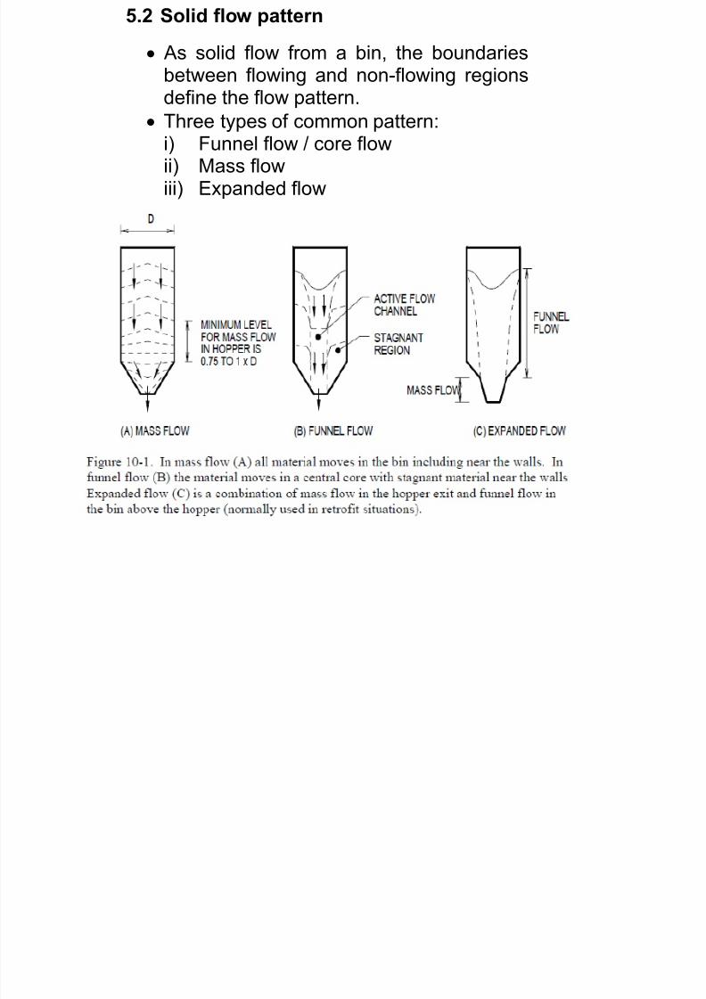
As solid flow from a bin, the boundariesbetween flowing and non-flowing regionsdefine the flow pattern.
Three types of common pattern:i) Funnel flow / core flowii) Mass flowiii) Expanded flow

7/21/2019 hopper design.pdf
http://slidepdf.com/reader/full/hopper-designpdf 3/31
7/21/2019 hopper design.pdf
http://slidepdf.com/reader/full/hopper-designpdf 4/31
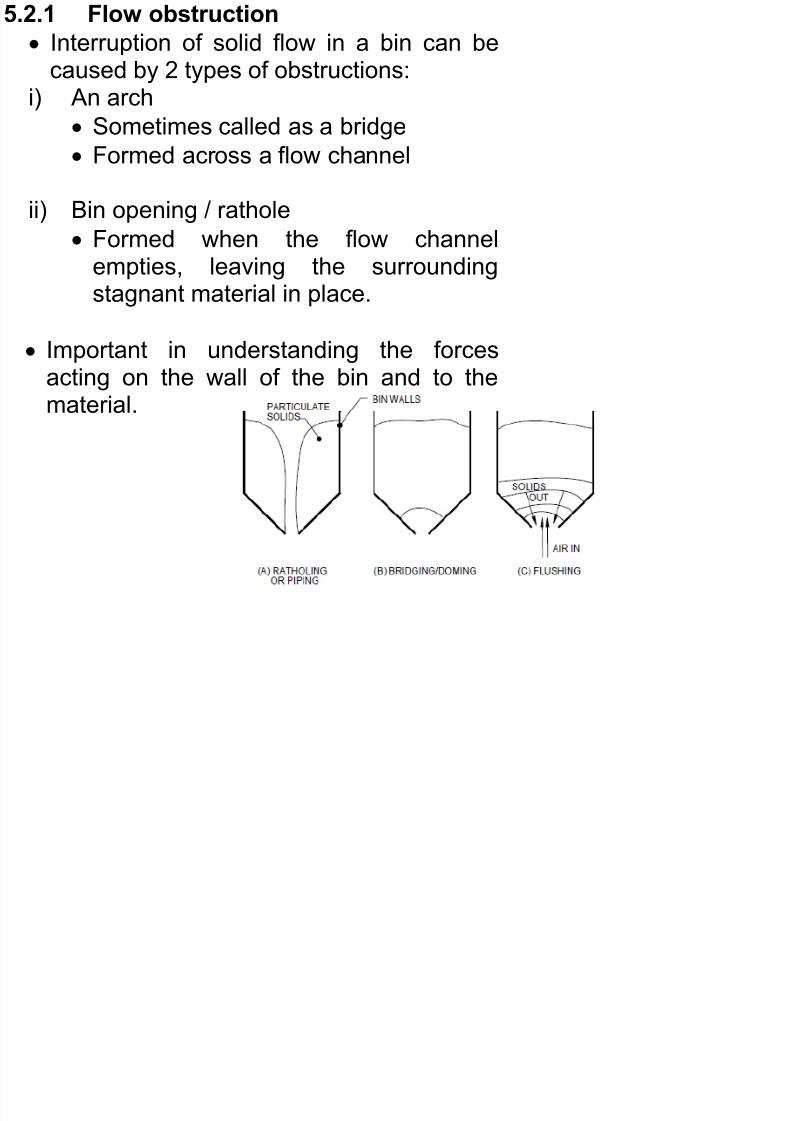
5.2.1 Flow obstruction
Interruption of solid flow in a bin can becaused by 2 types of obstructions:
i) An arch
Sometimes called as a bridge Formed across a flow channel
ii) Bin opening / rathole
Formed when the flow channel
empties, leaving the surroundingstagnant material in place.
Important in understanding the forcesacting on the wall of the bin and to the
material.
7/21/2019 hopper design.pdf
http://slidepdf.com/reader/full/hopper-designpdf 5/31
5.3 Types of flow pattern
5.3.1 Funnel flow / core flow:
Occurs in bin with flat bottom or hoppe
having slopes too shallow or too rough toallow solid to slide along the wall duringthe flow.
Funnel flow through an entire bin - Rathole,
formed when stagnant materials gainssufficient strength to remain in place as flochannel empties
Material near to the bin wall becomesstagnant.
First in, last out or do not come out at all.
Rathole / pipe could form.

7/21/2019 hopper design.pdf
http://slidepdf.com/reader/full/hopper-designpdf 6/31
In severe cases, the material can form abridge or arch over the dischargedopening.
The flow channel may not well defined-particle segregation might occur.-material surrounding the channel may
be unstable-this will cause stop and start flowing,pulsating or “jelly” flow. -could lead to the damage of material
structure.
As bin emptied; solid continually slough ofthe top surface into the channel.
7/21/2019 hopper design.pdf
http://slidepdf.com/reader/full/hopper-designpdf 7/31
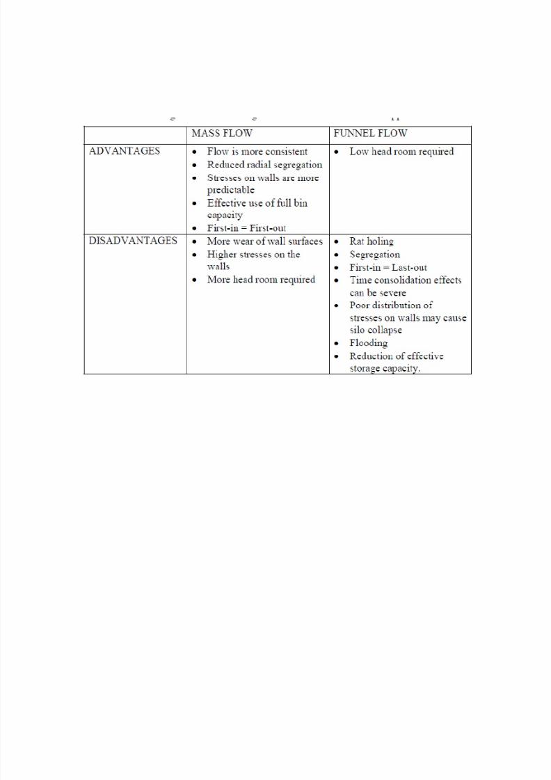
Storage bin having a funnel flow pattern ismost common in industry.
the design do not consider thestagnant materials.
thus, resulting in less dischargedcapacity.
Funnel flow is usually the least costlydesign.
It has several disadvantages whenhandling certain materials:
7/21/2019 hopper design.pdf
http://slidepdf.com/reader/full/hopper-designpdf 8/31
i) Flow rate from the discharged openingcan be erratic:
Arches tends to form and break. Flow channel becomes unstable.
Upset volumetric feeder installed atthe silo discharged
Powder density at discharged varywidely due to varying stresses in flow.
ii) Fine powders : Flush/aerated uncontrollably
Sudden collapse of rathole/arch
7/21/2019 hopper design.pdf
http://slidepdf.com/reader/full/hopper-designpdf 9/31
i) Caking/degrading of solid:
Left under consolidating stresses in
the stagnant areas.
ii) A stable rathole/ pipe formed
Stagnant material gain sufficienstrength to remain stagnant.
iii) Level indicator
Would not give correct signal onmaterials level.
Submerged in stagnant area
7/21/2019 hopper design.pdf
http://slidepdf.com/reader/full/hopper-designpdf 10/31
Despite all of the above, funnel flow is still
adequate for (advantage) :i) Non-caking or non-degradableii) Discharge opening adequately sized to
prevent bridging/ratholing.
However, many mechanical devices couldbe used to promote flow.
7/21/2019 hopper design.pdf
http://slidepdf.com/reader/full/hopper-designpdf 11/31
5.3.2 Mass flow:
Occurs in bin having steep and smoothhoppers.
Material discharges are fully active.
Flow channel coincides with the bin andhopper walls i.e all materials is in motionand sliding against the wall of bin and
hopper.
7/21/2019 hopper design.pdf
http://slidepdf.com/reader/full/hopper-designpdf 12/31
Advantages:
i) Erratic flow, channeling and flooding o
powders are avoided.
ii) Stagnant regions in the silo areeliminated.
iii) First in, first out flow occurs. Resulting inminimizing caking, degrading andsegregation during process.
iv) Little particle segregation or eliminated
v) Uniform flow at the hopper outlet
flow is easily controlled
pressures are well predictable.
Di d t
7/21/2019 hopper design.pdf
http://slidepdf.com/reader/full/hopper-designpdf 13/31
Disadvantages:
i) Friction between moving solids and thesilo.
resulting in erosion of the wall could give rise to contamination of the
solids by the material of the hopperwall.
Serious erosion of the wall material.
ii) For conical hoppers, the slope anglerequired to ensure mass flow dependson the powder-powder friction and thepowder-wall friction.
There is no such thing as mass flowhopper- a hopper that gives mass flowwith one powder may give core flow with
another.
7/21/2019 hopper design.pdf
http://slidepdf.com/reader/full/hopper-designpdf 14/31
Expanded flow:
Term used to describe flow in a vessel thatcombines a core flow converging hopperwith a mass flow attached below it.
The mass flow hopper section ensures auniform, controlled flow from the outlet. Itsupper diameter is sized such that nostable pipe can form in the core flow
hopper portion above it.

7/21/2019 hopper design.pdf
http://slidepdf.com/reader/full/hopper-designpdf 15/31
Expanded flow is used where a uniformdischarged in desired, but where space o
cost restrictions rule out a fully mass flowbin.
This arrangement can be used to modifyexisting funnel flow bins to correct flowproblems.
Multiple mass flow hoppers are sometimesmounted under a large core flow silo.
7/21/2019 hopper design.pdf
http://slidepdf.com/reader/full/hopper-designpdf 16/31
7/21/2019 hopper design.pdf
http://slidepdf.com/reader/full/hopper-designpdf 17/31
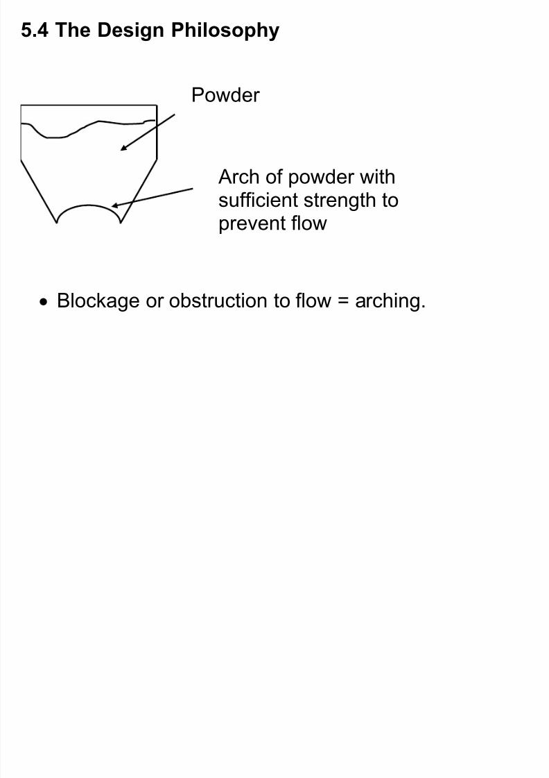
5.4 The Design Philosophy
Blockage or obstruction to flow = arching.
Arch of powder with
sufficient strength toprevent flow
Powder
7/21/2019 hopper design.pdf
http://slidepdf.com/reader/full/hopper-designpdf 18/31
powders develop strength under the
action of compacting stresses the greater the compacting stress, thegreater the strength developed
(Free-flowing solids such as coarse sand willnever develop compacting stress)
7/21/2019 hopper design.pdf
http://slidepdf.com/reader/full/hopper-designpdf 19/31
5.5 Flow- no flow criterion
Flow to occur:
strength developed by the solids under theaction of consolidating pressure to supportobstruction to flow is less than gravity floof the solids.
An arch occurs:
when the strength developed by the solidgreater than the stresses acting within thesurface of the arch.
The hopper flow factor (ff )
the ff relates the stress developed in aparticulate solid within the compacting
stress acting in a particular hopper.
7/21/2019 hopper design.pdf
http://slidepdf.com/reader/full/hopper-designpdf 20/31
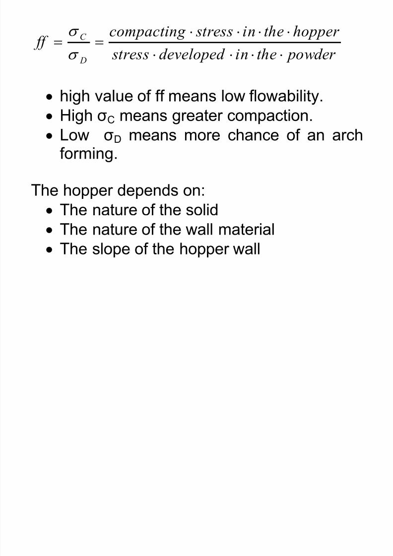
powder theindeveloped stress
hopper thein stresscompacting ff
D
C
high value of ff means low flowability.
High σC means greater compaction.
Low σD means more chance of an archforming.
The hopper depends on:
The nature of the solid The nature of the wall material
The slope of the hopper wall
7/21/2019 hopper design.pdf
http://slidepdf.com/reader/full/hopper-designpdf 21/31
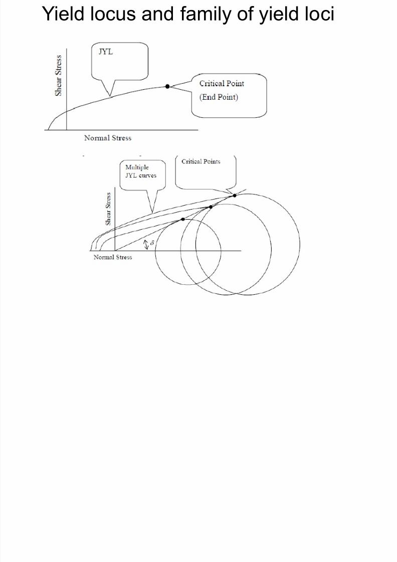
5.5.2 Powder flow function
the unconfined yield stress, σY of the solid
varies with compacting stress, σC ;i.e:
C y fn
the relationship is determinedexperimentally
the relationship is called powder flowfunction
7/21/2019 hopper design.pdf
http://slidepdf.com/reader/full/hopper-designpdf 22/31
7/21/2019 hopper design.pdf
http://slidepdf.com/reader/full/hopper-designpdf 23/31
Yi ld l d f il f i ld l i
7/21/2019 hopper design.pdf
http://slidepdf.com/reader/full/hopper-designpdf 24/31
Yield locus and family of yield loci
D t i ti f d
7/21/2019 hopper design.pdf
http://slidepdf.com/reader/full/hopper-designpdf 25/31
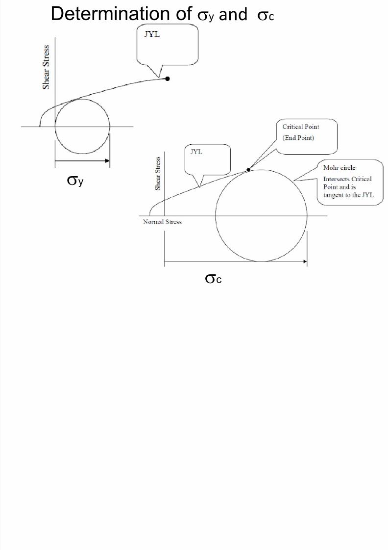
Determination of y and c
y
c
Critical condition for flow
7/21/2019 hopper design.pdf
http://slidepdf.com/reader/full/hopper-designpdf 26/31
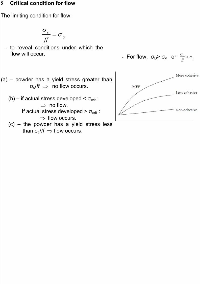
Critical condition for flow
he limiting condition for flow:
y
c
ff
- to reveal conditions under which theflow will occur.
(a) – powder has a yield stress greater than
σc/ff no flow occurs.
(b) – if actual stress developed < σcrit :
no flow.If actual stress developed > σcrit :
flow occurs.(c) – the powder has a yield stress less
than σc/ff flow occurs.
- For flow, σD> σy or y
C
ff
D t i ti f d d f
7/21/2019 hopper design.pdf
http://slidepdf.com/reader/full/hopper-designpdf 27/31
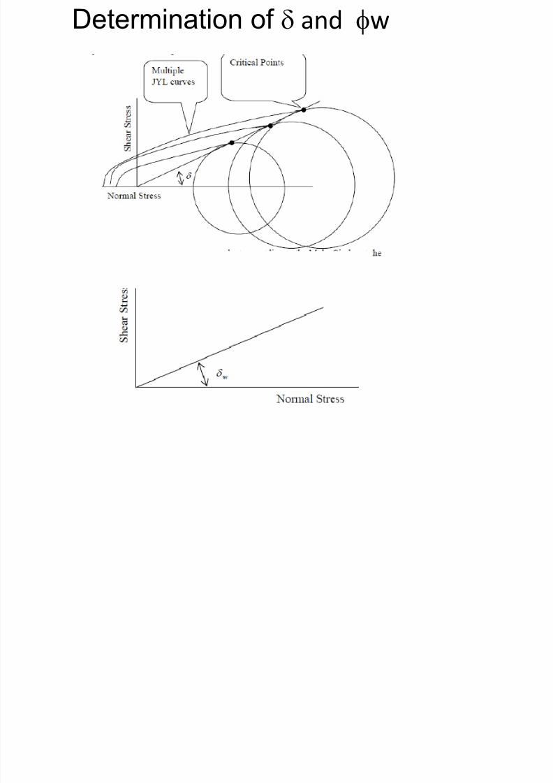
Determination of d and fw
Critical outlet dimension
7/21/2019 hopper design.pdf
http://slidepdf.com/reader/full/hopper-designpdf 28/31
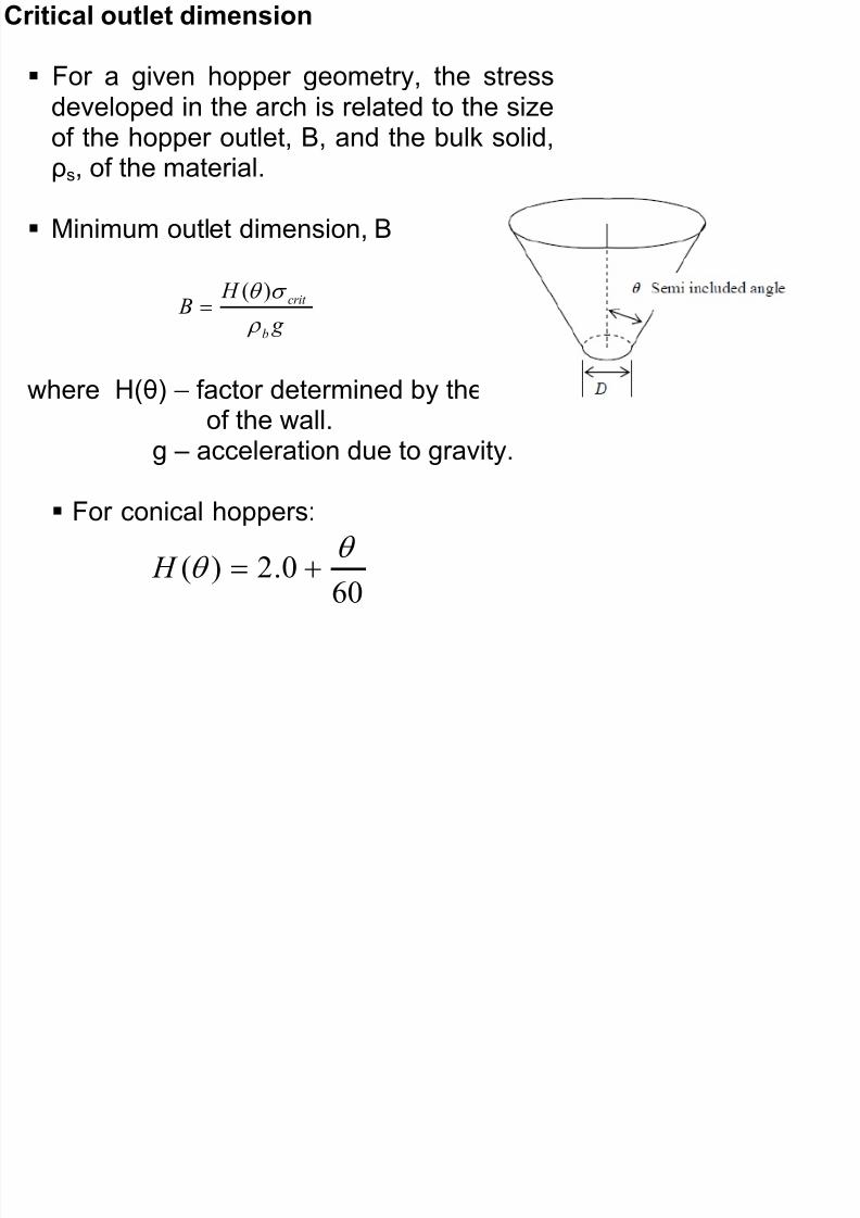
Critical outlet dimension
For a given hopper geometry, the stressdeveloped in the arch is related to the sizeof the hopper outlet, B, and the bulk solid,ρs, of the material.
Minimum outlet dimension, B
g
H B
b
crit
)(
where H(θ) – factor determined by the slopeof the wall.
g – acceleration due to gravity.
For conical hoppers:
60
0.2)(
H
C iti l O tl t Di i
7/21/2019 hopper design.pdf
http://slidepdf.com/reader/full/hopper-designpdf 29/31
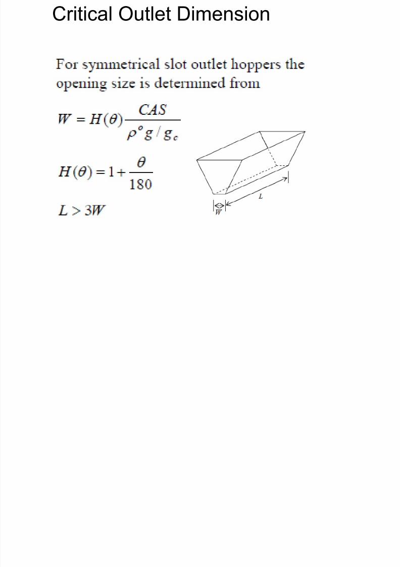
Critical Outlet Dimension

7/21/2019 hopper design.pdf
http://slidepdf.com/reader/full/hopper-designpdf 30/31
Hopper flow factor values for conical channels, d=50o

7/21/2019 hopper design.pdf
http://slidepdf.com/reader/full/hopper-designpdf 31/31