
Hong Chen - AMSStcct.amss.ac.cn/newsletter/2016/201608/images/hong.pdf · Hong Chen State Key...
42
2016 Chinese Control Conference, Chengdu Triple-step Nonlinear Control Design: Methodology and Automotive Applications Hong Chen State Key Laboratory of Automotive Simulation and Control Jilin University, China
Transcript of Hong Chen - AMSStcct.amss.ac.cn/newsletter/2016/201608/images/hong.pdf · Hong Chen State Key...
2016 Chinese Control Conference, Chengdu
Triple-step Nonlinear Control Design: Methodology and Automotive Applications
Hong Chen State Key Laboratory of Automotive Simulation and Control
Jilin University, China
❈ Motivation
❈ Triple-Step Design Technique
❈ Automotive Applications: Case Study
❈ Conclusions
Outline 2
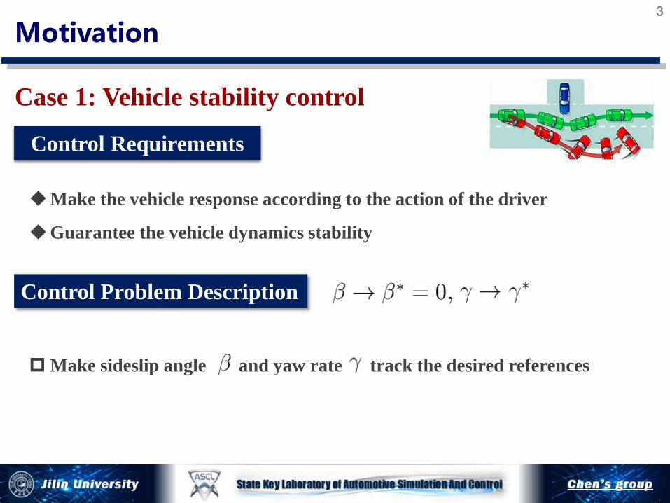
Case 1: Vehicle stability control
Control Requirements
Make the vehicle response according to the action of the driver
Guarantee the vehicle dynamics stability
Motivation 3
Make sideslip angle and yaw rate track the desired references
Control Problem Description

Case 1: Vehicle stability control
Motivation 4
Make sideslip angle and yaw rate track the desired values
Control Output
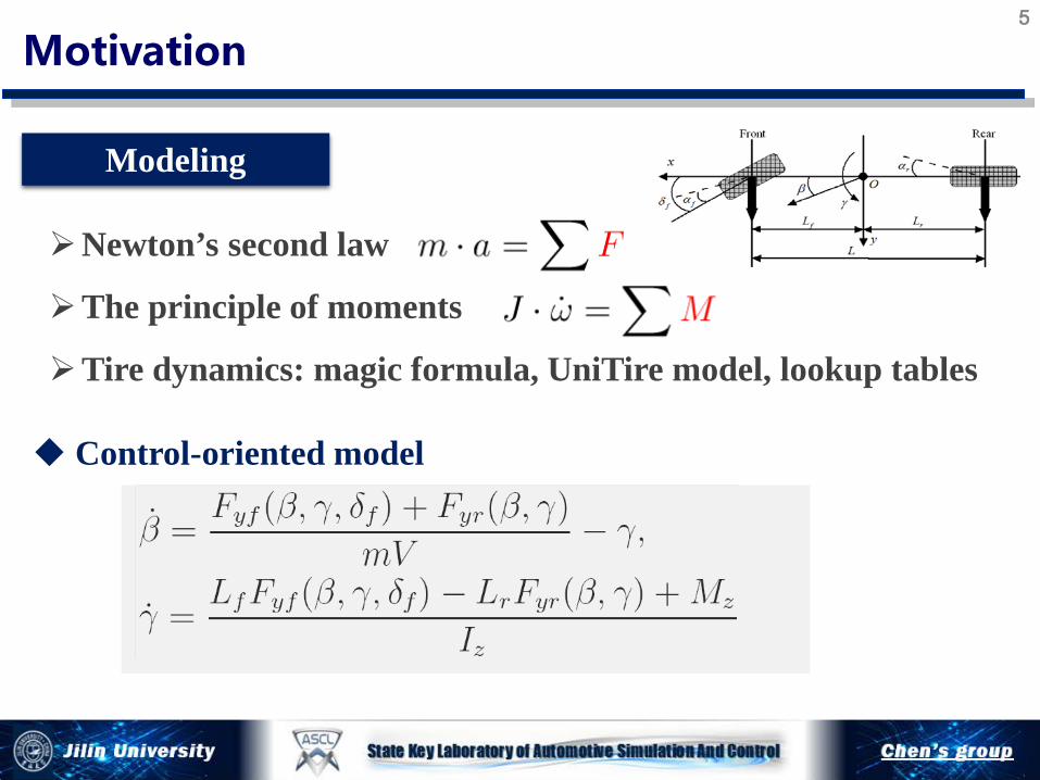
Modeling
Control-oriented model
Motivation 5
Newton’s second law
The principle of moments
Tire dynamics: magic formula, UniTire model, lookup tables

Modeling
Motivation 6
Control outputs:
Control inputs:
Time varying parameters:
-0.5 -0.4 -0.3 -0.2 -0.1 0 0.1 0.2 0.3 0.4 0.5-8000
-6000
-4000
-2000
0
2000
4000
6000
8000
α f (rad)
Fyf
(N)
Lateral Force of Tyre - Fyf (αf,µ)
µ = 0.1µ = 0.3µ = 0.5µ = 0.7µ = 0.9
-0.5 -0.4 -0.3 -0.2 -0.1 0 0.1 0.2 0.3 0.4 0.5-5000
0
5000
α r (rad)
Fyr
(N
)
Lateral Force of Tyre - Fyr(αr,µ)
µ = 0.1µ = 0.3µ = 0.5µ = 0.7µ = 0.9
With time varying parameters Lookup tables in the right side Non-affine in control input
How to design the controller

Balance
Control Requirements
Motivation ASME JDSMC (2011) VSD (2011) Mechatronics (2011)
Improve smoothness of shift process
7
Case 2:Shift control of automated transmissions
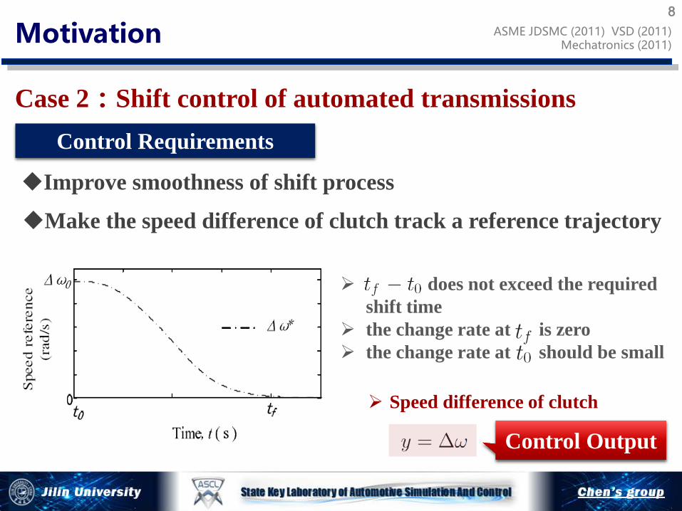
Control Requirements
Motivation ASME JDSMC (2011) VSD (2011) Mechatronics (2011)
Improve smoothness of shift process
Make the speed difference of clutch track a reference trajectory
Speed difference of clutch
does not exceed the required shift time
the change rate at is zero the change rate at should be small
Control Output
8
Case 2:Shift control of automated transmissions

Motivation ASME JDSMC (2011) VSD (2011) Mechatronics (2011)
Inertia Phase
Valve pressure dynamics The principle of moments
9
Case2:Shift control of transmissions
Modeling
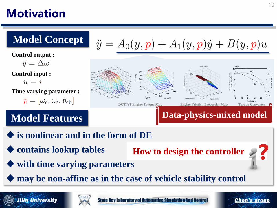
is nonlinear and in the form of DE contains lookup tables with time varying parameters may be non-affine as in the case of vehicle stability control
Model Concept
Control input :
Time varying parameter :
Control output :
Model Features Data-physics-mixed model
Motivation
How to design the controller
DCT/AT Engine Torque Map Torque Converter Engine Friction Properties Map
10
Triple Step Design Technique
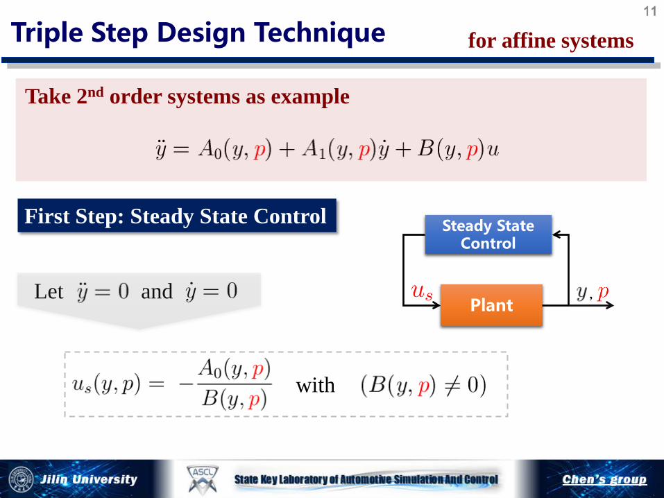
Take 2nd order systems as example
First Step: Steady State Control
, Plant
Steady State Control
Let and
with
for affine systems 11
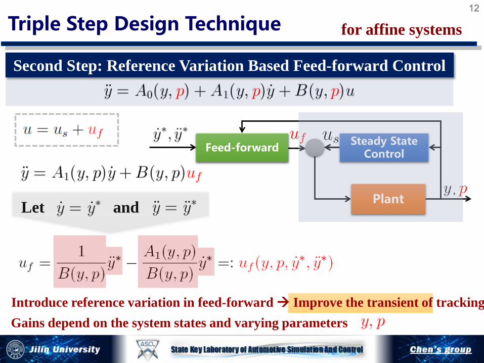
Introduce reference variation in feed-forward Improve the transient of tracking
, Plant
Steady State Control Feed-forward
Let and
Gains depend on the system states and varying parameters
Triple Step Design Technique for affine systems
Second Step: Reference Variation Based Feed-forward Control
12
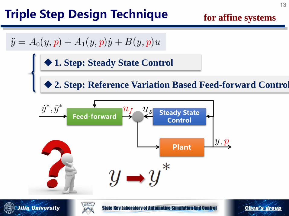
, Plant
Steady State Control Feed-forward
2. Step: Reference Variation Based Feed-forward Control
1. Step: Steady State Control
Triple Step Design Technique for affine systems 13

Third Step: Error Feedback Control
Error dynamics
Triple Step Design Technique for affine systems 14
Define Lyapunov function

Third Step: Error Feedback Control
Gain-scheduling PID
LaSalle's invariance principle
Triple Step Design Technique for affine systems 15
Closed-loop error dynamics
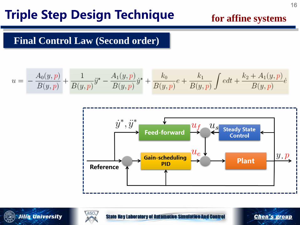
Final Control Law (Second order)
Triple Step Design Technique for affine systems 16
If
If
If
If
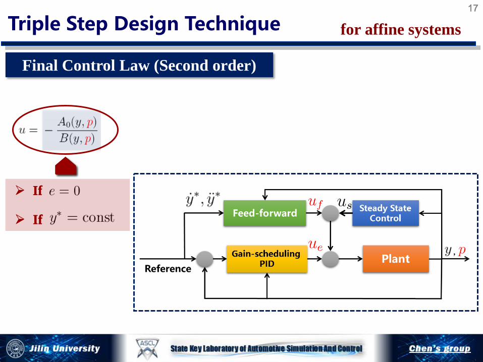
Final Control Law (Second order)
Triple Step Design Technique for affine systems 17

If
If
If
If
Final Control Law (Second order)
Triple Step Design Technique for affine systems 18
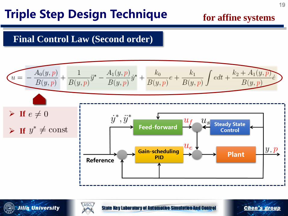
Final Control Law (Second order)
Triple Step Design Technique for affine systems 19
If
If
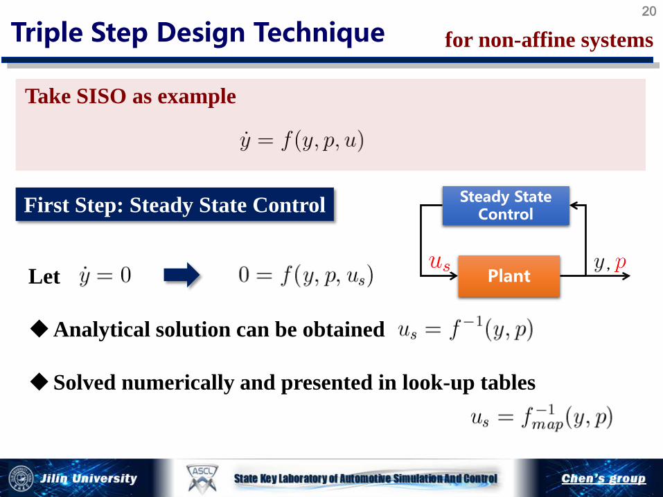
Let Analytical solution can be obtained Solved numerically and presented in look-up tables
First Step: Steady State Control
Take SISO as example
Triple Step Design Technique for non-affine systems
, Plant
Steady State Control
20

Second Step: Reference Variation Based Feed-forward Control
Let
with
Triple Step Design Technique for non-affine systems
, Plant
Steady State Control Feed-forward
Let
21

Third Step: Error Feedback Control
Let
,
Feed-forward
Plant
Steady State Control
Gain-scheduling PI Reference
Triple Step Design Technique for non-affine systems 22
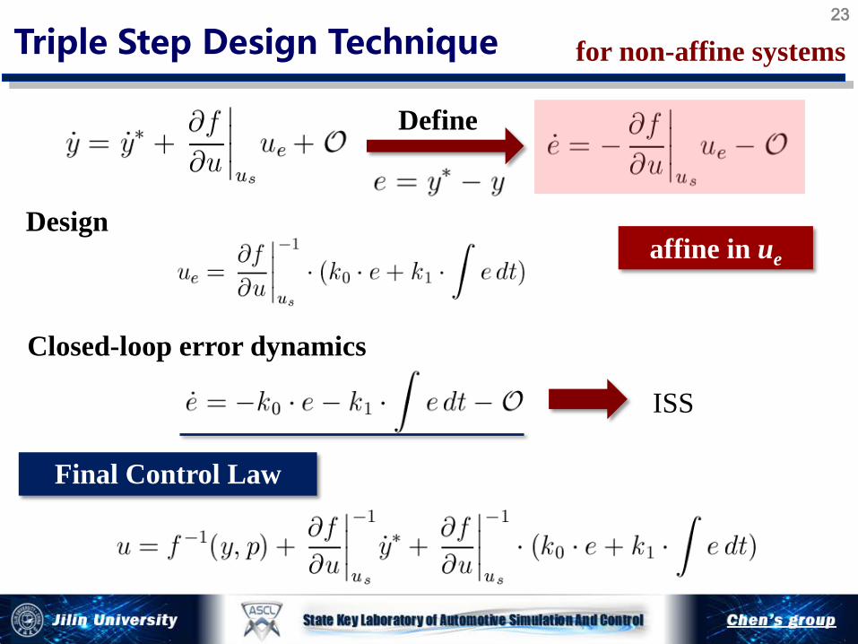
ISS
Design
Closed-loop error dynamics
Define
Final Control Law
Triple Step Design Technique for non-affine systems 23
affine in ue
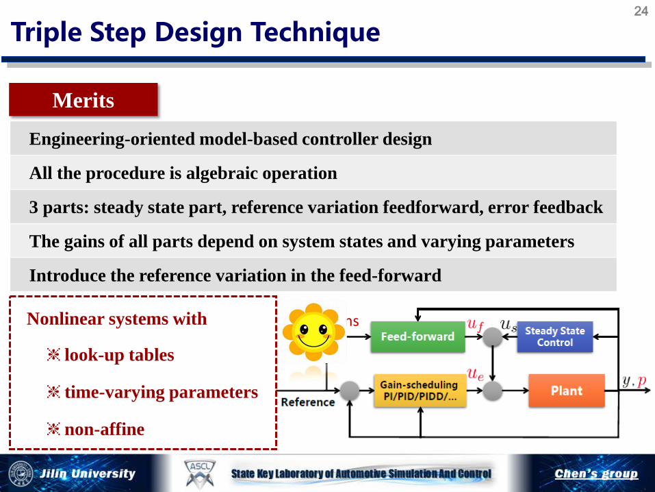
Engineering-oriented model-based controller design
All the procedure is algebraic operation
3 parts: steady state part, reference variation feedforward, error feedback
The gains of all parts depend on system states and varying parameters
Introduce the reference variation in the feed-forward
Merits
Triple Step Design Technique 24
variations Nonlinear systems with
❈ look-up tables
❈ time-varying parameters
❈ non-affine
Merits
Triple Step Design Technique 25
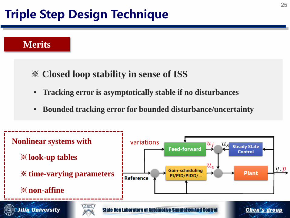
variations Nonlinear systems with
❈ look-up tables
❈ time-varying parameters
❈ non-affine
❈ Closed loop stability in sense of ISS
• Tracking error is asymptotically stable if no disturbances
• Bounded tracking error for bounded disturbance/uncertainty

Case study I : Vehicle Dynamics Control in EV J FRANKLIN I (2014)
2-Input-2-Output, 2nd Order, Non-affine
Stability Control of In-wheel Motor Electric Vehicles
First step: steady state control
• Implemented by look-up tables
26
Case study I : Vehicle Dynamics Control in EV
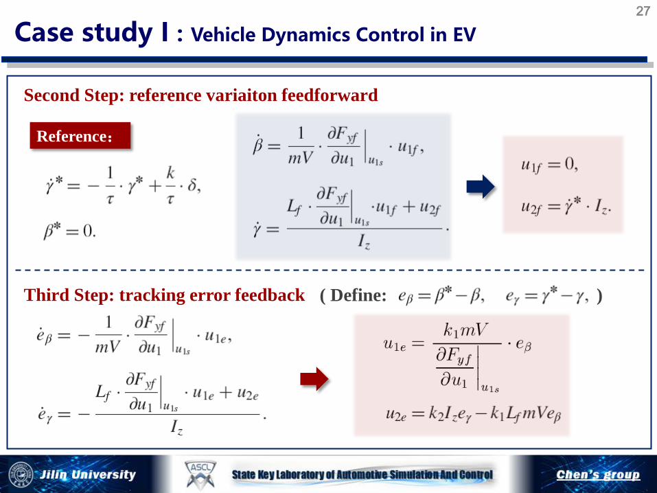
Second Step: reference variaiton feedforward
Third Step: tracking error feedback
Reference:
( Define: )
27
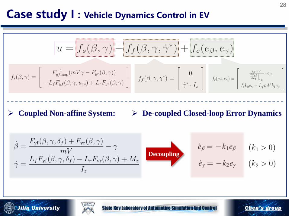
Case study I : Vehicle Dynamics Control in EV 28
Coupled Non-affine System: De-coupled Closed-loop Error Dynamics
Decoupling
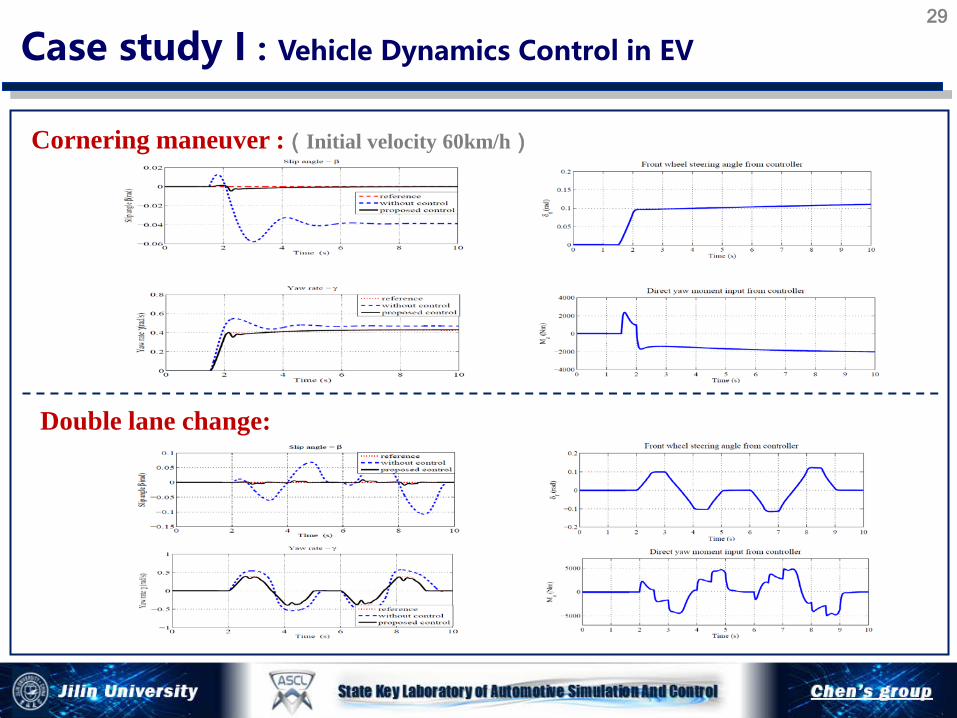
Cornering maneuver :(Initial velocity 60km/h)
Double lane change:
Case study I : Vehicle Dynamics Control in EV 29
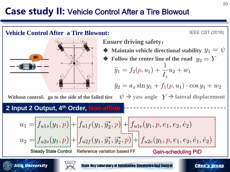
2 Input 2 Output, 4th Order, Non-affine
IEEE CST (2016)
Steady State Control Reference variation based FF Gain-scheduling PID
Vehicle Control After a Tire Blowout:
Case study II: Vehicle Control After a Tire Blowout
Without control:go to the side of the failed tire
Ensure driving safety: Maintain vehicle directional stability Follow the center line of the road
yaw angle lateral displacement
30

Simulation Results Test 1: Left front bursts: straight road
Case study II: Vehicle Control After a Tire Blowout
Improve Directional
Stability
Path Following
Performance
31
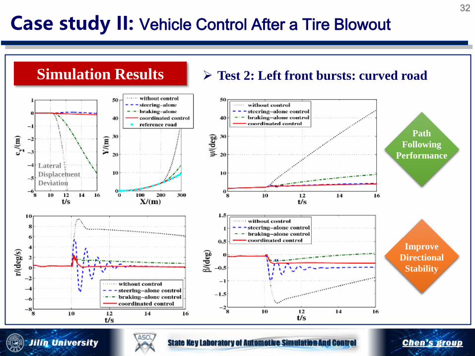
Case study II: Vehicle Control After a Tire Blowout
Simulation Results Test 2: Left front bursts: curved road
Improve Directional
Stability
Path Following
Performance Lateral Displacement Deviation
32

Description: Rail pressure stable and track a given reference
Detailed control specifications
Objective: Inject precise and desired quantity of fuel into cylinder
Settling time: within 100ms
Steady state error: <1 bar
Maximum fluctuation: <5 bar
System description
Control output: Rail Pressure Control input: Inlet flow of the high
pressure pump
ry p=
uu q=
IET CTA (2014) ACC (2014)
Rail Pressure System
Case Study III : Rail Pressure Control in GDI Engines
GDI
33

0
input
Control Valve
High Pressure Pump
Check Valve
Plunger
Pressure Dynamics in HPP:
Motion Dynamics of Plunger:
Outflow:
0
input
output
Common Rail Common Rail Pressure:
Outflow:
Case Study III : Rail Pressure Control in GDI Engines 34
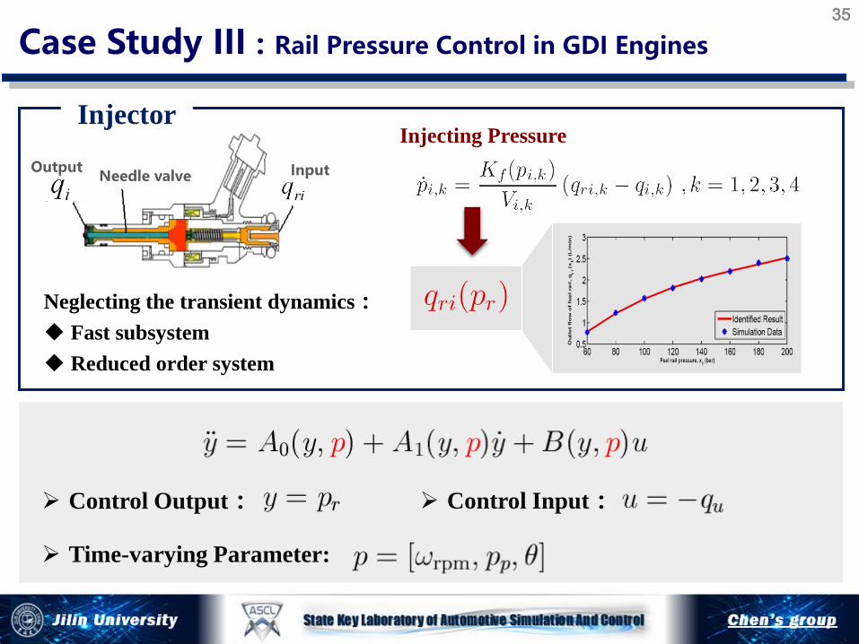
Needle valve Input Output
Neglecting the transient dynamics: Fast subsystem Reduced order system
Injecting Pressure Injector
Case Study III : Rail Pressure Control in GDI Engines
Control Input: Control Output:
Time-varying Parameter:
35
0 1
* * * *2
1
1 221
0 221
( ) ( )( , ) ( ) ( 1) ,
( )( , , , ) 2 ( ( ) ),
( )( , ) 2 (1 ),
( )( , ) 2 ,
( )( , ) 2
r r
p p ps p rpm ri p
r r
p r ff p ri
f r
p rP p
f
p rI p
f
pD p r
dh V Vu y p A q y q p y
d V VV V K
u y p y y p y p q y pK V
V Vf y p p y k k
KV V
f y p p y k kKV V
f x p p p
θ θω η
θθη
θη
θη
θ
= + − − + −
= − − +
= − − +
= − −
= − −
1 221
( ( )),r fri r
f r
Kk k q p
K Vη+ −
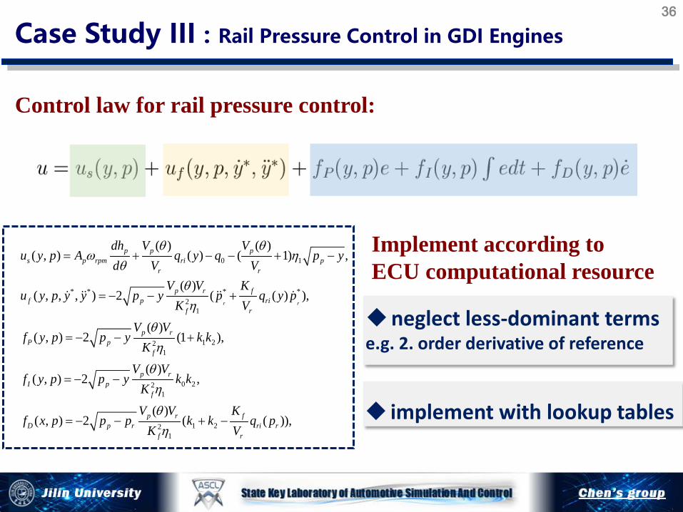
Control law for rail pressure control:
Case Study III : Rail Pressure Control in GDI Engines
Implement according to ECU computational resource
neglect less-dominant terms e.g. 2. order derivative of reference
implement with lookup tables
36

GDI HiL Platform
Engine speed:1000,2000,3000,4000, 5000 , 6000rpm;Load:20-75 (%),
Engine speed:1000-3500 rpm Load:15-75 (%)
GDI Testbench
Case Study III : Rail Pressure Control in GDI Engines
Tracking error
Rail pressure
operating conditions
Tracking error
Rail pressure
operating conditions
37
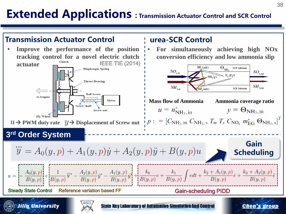
Extended Applications : Transmission Actuator Control and SCR Control
IEEE TIE (2014)
Transmission Actuator Control urea-SCR Control
3rd Order System
Steady State Control Reference variation based FF Gain-scheduling PIDD
Gain Scheduling
• Improve the performance of the position tracking control for a novel electric clutch actuator
• For simultaneously achieving high NOx conversion efficiency and low ammonia slip
PWM duty rate Displacement of Screw nut
Ammonia coverage ratio Mass flow of Ammonia
38

Nonlinear systems
Conclusions 39
with lookup tables with time-varying parameters may be non-affine Triple step design technique
Engineering-oriented model-based controller design
3 parts: steady state, reference variation feedforward, error feedback
The gains of all parts depend on system states and varying parameters
Introduce the reference variation in the feed-forward
Tracking error stability in the sense of ISS
Case study rail pressure control, shift control (2nd order, affine) vehicle stability control (MIMO, non-affine) actuator control and SCR control (3rd order, affine)
1. H. Chen, X. Gong, Q. Liu and Y. Hu. Triple-step method to design non-linear controller for rail pressure of gasoline direct injection engines. IET CTA, 8(11): 948-959, 2014
2. B. Gao, H. Chen, Q. Liu and H. Chu. Position control of electric clutch actuator using a triple-step nonlinear method. IEEE T Industrial Electronics , 61(12):6995-7003, 2014
3. Q. Liu, H. Chen, B. Gao, Y. Gao. Shift control of Dual Clutch Transmission using Triple-Step nonlinear method. IFAC World Congress, 47(3): 5884-5889, 2014.
4. Y. Hu, D, Hu, Y, Fan, et al. Electronic throttle controller design using a triple-step nonlinear method[C]. Proc. 11th WCICA, 2014: 816-821.
5. H. Zhao, B. Gao, B. Ren and H. Chen. Integrated control of in-wheel motor electric vehicles using a triple-step nonlinear method. J. Franklin Institute, 352(2):519-540, 2015
6. Q. Liu, X. Gong, H. Chen, B. Xin and P. Sun. Nonlinear GDI rail pressure control: Design, analysis and experimental implementation. Proc. 34th CCC, 8132-8139, 2015
7. F. Wang, H. Chen, D. Cao. Nonlinear Coordinated Motion Control of Road Vehicles After a Tire Blowout. IEEE T Control System Technology, 24(3): 956 - 970, 2016
8. H. Chu, B. Gao, W. Gu and H. Chen. Low Speed Control for Permanent Magnet DC Torque Motor Using Observer-based Nonlinear Triple-Step Controller. IEEE T Industrial Electronics (online).
9. H. Zhao, Y. Hu, X. Gong, H. Chen. Modelling and control of urea-SCR systems through the triple-step non-linear method in consideration of time-varying parameters and reference dynamics. Transactions of the Institute of Measurement and Control (accept).
10. …
References 40

Acknowledgement
Bingzhao Gao Fei Wang Qifang Liu Haiyan Zhao Yunfeng Hu Hongqing Chu Xun Gong
41
Pengyuan Sun, FAW Baiyu Xin, FAW

Thank you!
2016 Chinese Control Conference, Chengdu


