Homework 3: Programmable Shaders
6
Homework 3: Programmable Shaders Introduction to Computer Graphics and Imaging (Summer 2012), Stanford University Due Monday, July 23, 11:59pm Warning: The coding portion of this homework involves features of OpenGL that are much newer than ones we have used in previous assignments. Thus, there are some odds they won’t work on your machine. Even if you don’t start coding for the assignment early, do try compiling and running the skeleton code ASAP to make sure everything is functional. If there is an issue with your hardware, you may need to code this assignment in person on the Myth machines (forwarding may also fail). In the written portion of this problem set, we’ll explore properties of and computations involv- ing barycentric coordinates, introduced in Lecture 4. These coordinates are used to interpolate normals, textures, depths, and other values across triangle faces, so it is important to understand how they behave. To begin with, let’s say we have a triangle with vertices ~ a, ~ b, and ~ c in R 2 . We’ll define the signed area of triangle abc as follows: A( abc)= 1 2 b x - a x c x - a x b y - a y c y - a y Problem 1 (10 points). (a) Use cross products to show that the absolute value of A( abc) is indeed the area of the triangle that we expect. (b) Show that A( abc) is positive when ~ a, ~ b, and ~ c are in counterclockwise order and negative otherwise. Drawing pictures to demonstrate the solution for part (b) is good enough: no need for a formal proof. Now, let’s take a point ~ p in triangle abc. Assume that ~ a, ~ b, and ~ c are given in counterclockwise order. Then, we can apply the formula above to yield straightforward expressions for barycentric coordinates. Problem 2 (10 points). Define the barycentric coordinates of ~ p using the signed area formula above. Show that your coordinates always sum to 1 and that they are all positive exactly when ~ p is inside the triangle abc. Our definition of barycentric coordinates in terms of areas seems somewhat arbitrary! After all, we could take any three numbers as functions of vertex positions and normalize to 1. Thankfully, we won’t make you prove it, but the following relationship holds uniquely: ~ p = α a ~ a + α b ~ b + α c ~ c where ~ p has barycentric coordinates (α a , α b , α c ) summing to 1. 1
Transcript of Homework 3: Programmable Shaders
Homework 3: Programmable ShadersIntroduction to Computer Graphics and Imaging (Summer 2012), Stanford University
Due Monday, July 23, 11:59pm
Warning: The coding portion of this homework involves features of OpenGLthat are much newer than ones we have used in previous assignments. Thus,there are some odds they won’t work on your machine. Even if you don’t startcoding for the assignment early, do try compiling and running the skeletoncode ASAP to make sure everything is functional. If there is an issue withyour hardware, you may need to code this assignment in person on the Mythmachines (forwarding may also fail).
In the written portion of this problem set, we’ll explore properties of and computations involv-ing barycentric coordinates, introduced in Lecture 4. These coordinates are used to interpolatenormals, textures, depths, and other values across triangle faces, so it is important to understandhow they behave.
To begin with, let’s say we have a triangle with vertices~a,~b, and~c in R2. We’ll define the signedarea of triangle abc as follows:
A(abc) =12
∣∣∣∣ bx − ax cx − axby − ay cy − ay
∣∣∣∣Problem 1 (10 points). (a) Use cross products to show that the absolute value of A(abc) is indeed the areaof the triangle that we expect. (b) Show that A(abc) is positive when ~a,~b, and ~c are in counterclockwiseorder and negative otherwise. Drawing pictures to demonstrate the solution for part (b) is good enough: noneed for a formal proof.
Now, let’s take a point ~p in triangle abc. Assume that~a,~b, and~c are given in counterclockwiseorder. Then, we can apply the formula above to yield straightforward expressions for barycentriccoordinates.
Problem 2 (10 points). Define the barycentric coordinates of ~p using the signed area formula above. Showthat your coordinates always sum to 1 and that they are all positive exactly when ~p is inside the triangleabc.
Our definition of barycentric coordinates in terms of areas seems somewhat arbitrary! After all,we could take any three numbers as functions of vertex positions and normalize to 1. Thankfully,we won’t make you prove it, but the following relationship holds uniquely:
~p = αa~a + αb~b + αc~c
where ~p has barycentric coordinates (αa, αb, αc) summing to 1.
1

Problem 3 (10 points). Use this formula to suggest a 2× 2 linear system that will yield two of the threebarycentric coordinates of ~p. Provide a formula for the third.
Hint: Do the second part of the problem first. Then plug in the third coordinate in our expression for~p and refactor into a linear system for αa and αb.
If you’ve done everything correctly so far, you should find that applying the standard formulafor the inverse of a 2× 2 matrix to your solution to Problem 3 yields your signed area formulafrom Problem 2. You can check this on scrap paper if you desire.
Now, let’s say we want to interpolate a function f smoothly given its values at~a,~b, and~c. Wewill label these values fa, fb, and fc, resp., and will use f (~p) to denote the interpolated functionwith values everywhere on R2 given by
f (~p) = αa fa + αb fb + αc fc
where the barycentric coordinates of ~p are (αa, αb, αc). It’s easy to see that f (~a) = fa, f (~b) = fb,and f (~c) = fc (make sure you understand why!). We also have one final important property:
Problem 4 (10 points). Take ~p1,~p2 ∈ R2. Show that f (t~p1 + (1− t)~p2) = t f (~p1) + (1− t) f (~p2) forany t ∈ R.
Comprehensive hint: Use barycentric coordinates to write
~p1 = α1a~a + α1
b~b + α1
c~c
~p2 = α2a~a + α2
b~b + α2
c~c
Now, define ~p = t~p1 + (1− t)~p2. Plug in our barycentric expressions for ~p1 and ~p2 above and refactor toyield the barycentric coordinates of ~p from the coefficients of~a,~b, and~c. Use these barycentric coordinatesto find f (~p) as it is defined above the problem, and refactor once again to get the final result.
This final result actually shows us that barycentric coordinates are the right way to interpolatedepths for the depth buffer (ignoring the nonlinearity we discussed in Lecture 4). Namely, if werestrict f to a line through ~p1 and ~p2, it looks linear.
By the way, just like Bresenham’s algorithm, there are incremental tricks for computing barycen-tric coordinates inside triangles given their values on the edges. Modern GPUs make use offragment-level parallelization and thus such tricks might not be useful.
In the coding half of this assignment,1 you will get some practice using GLSL to write shaders,which implicitly make use of barycentric coordinates and other tools to modify fragments, vertexpositions, and other data. Lecture 6 covers the basics of GLSL as well as the philosophy behindwriting shaders. Recall that the two most basic types of shaders in OpenGL are:
Vertex shaders These shaders modify the vertices of a triangulated piece of geometry. The defaultOpenGL vertex shader multiplies vertex coordinates by model-view and projection matricesand applies other aspects of the fixed-function pipeline, but we can write a shader of our ownto modify shape.
1Adapted from a nearly identical assignment used in Pat Hanrahan’s CS 148 course in Fall 2011.
2
Fragment shaders These shaders let us modify the method used to compute pixel colors, poten-tially employing textures and other external data.
OpenGL also allows for geometry shaders, but we won’t make use of them in CS 148.Some useful facts beyond what was covered in lecture to get you started writing shaders:
• The OpenGL “Orange Book” documents details of GLSL and can help you look up advancedfeatures and particular functionality. There also is some information in the “Red Book,” inthe course textbook, and in online tutorials.
• The entry point of a GLSL shader is the function main(), as in C. A vertex shader’s mainfunctionality is to compute gl Position, the position of the vertex, and a fragment shader’sfunctionality is to compute gl FragColor, the color of the fragment.
• GLSL has all the simple C data types. It also has built-in vector types vec2, vec3, and vec4
(with constructors like vec2(x,y)). You can access fields of these vectors as v.x/v.y/v.z/v.wor as v.r/v.g/v.b/v.a. You can extract the RGB part of an RGBA color by “swizzling:”c.rgb, and multiplying vectors does so element-wise. There are many useful helper functionsincluding dot(), cross(), length(), normalize(), and reflect().
The assignment this time comes with a makefile that should work on most systems, although itwill be evaluated on the Myth machines. It makes use of the OpenGL Extension Wrangler Library(GLEW) to deal with shaders. Visual Studio and Xcode users shouldn’t need any extra work touse this library. On Linux, you may need to install libglew-dev or download GLEW online (somesystems may need to change the makefile to say “-lGLEW” rather than “-lglew”).
Make sure you can compile and run the assignment ASAP, as GLSL support can be shaky fromone computer to another. To do so, first compile the included libst library and then ProgrammableShading.You actually won’t need to recompile these if you only change the shader files – shaders get com-piled separately at runtime. To run the program, you will use the incantation:
./ProgrammableShading vertShader fragShader lightProbeImg normalMapImg
Here, vertShader and fragShader are the shader files, and lightProbeImg and normalMapImg
are images that we will use in later parts of this assignment. For example, to run the defaultskeleton shaders, type:
./ProgrammableShading kernels/default.vert kernels/phong.frag
images/lightprobe.jpg images/normalmap.png
Navigation in this simple viewer uses the left mouse button to rotate and the right mousebutton to zoom. Pressing r resets the camera position, t toggles between displaying the plane anddisplaying the Utah teapot, and the arrow keys move the camera horizontally and vertically. Presss to take a screenshot and save it to screenshot.jpg.
Your first shader in GLSL will be a fragment shader implementing the Phong reflection model.Recall that Phong reflection separates specular, diffuse, and ambient reflection yielding a finalintensity of
I = Ma Ia + (~Lm · ~N)Md Id + (~Rm · ~V)s Ms Is
where
3
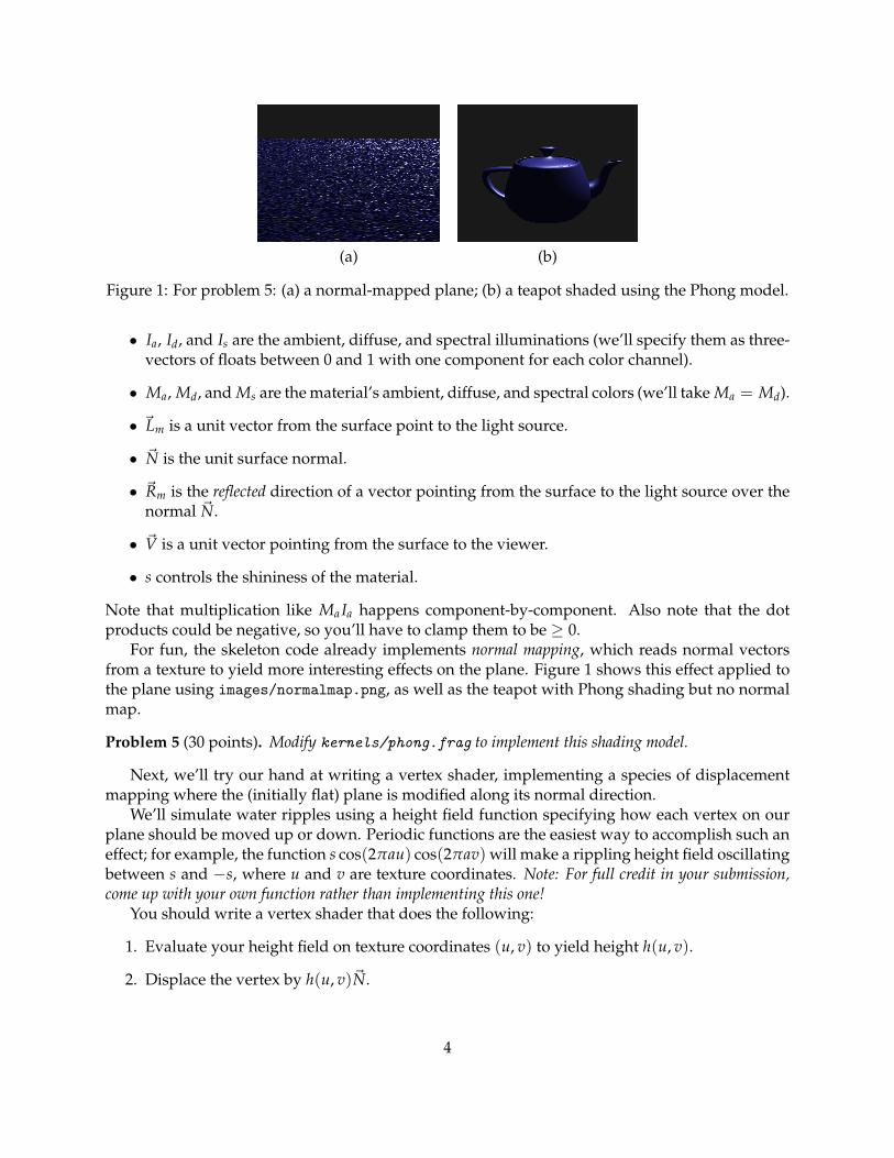
(a) (b)
Figure 1: For problem 5: (a) a normal-mapped plane; (b) a teapot shaded using the Phong model.
• Ia, Id, and Is are the ambient, diffuse, and spectral illuminations (we’ll specify them as three-vectors of floats between 0 and 1 with one component for each color channel).
• Ma, Md, and Ms are the material’s ambient, diffuse, and spectral colors (we’ll take Ma = Md).
• ~Lm is a unit vector from the surface point to the light source.
• ~N is the unit surface normal.
• ~Rm is the reflected direction of a vector pointing from the surface to the light source over thenormal ~N.
• ~V is a unit vector pointing from the surface to the viewer.
• s controls the shininess of the material.
Note that multiplication like Ma Ia happens component-by-component. Also note that the dotproducts could be negative, so you’ll have to clamp them to be ≥ 0.
For fun, the skeleton code already implements normal mapping, which reads normal vectorsfrom a texture to yield more interesting effects on the plane. Figure 1 shows this effect applied tothe plane using images/normalmap.png, as well as the teapot with Phong shading but no normalmap.
Problem 5 (30 points). Modify kernels/phong.frag to implement this shading model.
Next, we’ll try our hand at writing a vertex shader, implementing a species of displacementmapping where the (initially flat) plane is modified along its normal direction.
We’ll simulate water ripples using a height field function specifying how each vertex on ourplane should be moved up or down. Periodic functions are the easiest way to accomplish such aneffect; for example, the function s cos(2πau) cos(2πav) will make a rippling height field oscillatingbetween s and −s, where u and v are texture coordinates. Note: For full credit in your submission,come up with your own function rather than implementing this one!
You should write a vertex shader that does the following:
1. Evaluate your height field on texture coordinates (u, v) to yield height h(u, v).
2. Displace the vertex by h(u, v)~N.
4

Figure 2: For problem 6.
Since you just modified the geometry, however, you’ll need to do one more task. The normalto the plane used to be the constant (0, 1, 0), but now our surface contains ripples and must beshaded as such! Thus, you must also:
3. Compute a new unit normal, using either a closed form or finite differencing (look it up orask during office hours!).
Figure 2 shows proper output for one potential ripple function.
Problem 6 (30 points). Modify kernels/displacement.vert to implement your height field displace-ment shader. Be sure to output correct normals.
Optional Extra Credit
Shiny materials like metal reflect the surrounding environment. This is because these materialsadmit predominantly specular lighting. In class and in a future assignment, we’ll talk about raytracing as the “proper” solution to this problem, but it can be too slow for real-time applications.Instead, we’d like to compromise, using OpenGL’s fast rendering to obtain a plausible reflectionalrendering. We will use a technique called environment mapping (also known as reflection mapping)to achieve these effects. The trick is to use a light probe image encoding the color and intensity ofthe light coming in from all directions.
There are several ways to encode and decode such light information, but in this assignment wewill use spherical mapping from a mirror ball image. Note that our math below assumes the lightprobe was photographed using an orthographic projection, an obviously nonphysical assumptionbut one that simplifies the math considerably.
Let’s say we take a photo of a chrome ball in our scene, as in Figure 4(a). Since our ball onlyreflects specularly, the color we see at each surface point must come from a distinct light direction,illustrated in Figure 3(a). In the diagram, for each point on the surface, the direction of the lightsource that is illuminating that point from our camera perspective is shown with a green arrow.Note that on the top and bottom of the sphere, the light we see from the eye position is comingfrom directly behind the ball. In fact, as suggested in Figure 3(b), photographing half the spheretells us about light in all directions!
To extract lighting information from the light probe, we will assume that the direction andmagnitude of the vector from the camera to the light probe is the same as the vector from thedirection of our OpenGL scene camera to the point on the surface we are shading.
5

(a) (b)
(c) (d)
Figure 3: Images to explain the algorithm for problem 7.
(a) (b)
Figure 4: For problem 7.
Recall that the source of specular light reaching the viewer at ~V is the reflection of ~V across thenormal vector ~N. We’re assuming our probe and surface have approximately the same ~V, so weonly need to find the color of the point on the sphere that shares the same ~N!
Let’s say the center of the sphere is (0, 0, 0). Then, the point on the sphere with normal ~N issimply ~P = (0, 0, 0) + ~N (an interesting property of the unit sphere is that position and normalvectors are the same, shown in Figure 3(c)). We’re assuming an orthographic projection of the unitsphere, shown in Figure 3(d), so to find the right lookup on the probe image we simply removeone of the three coordinates! Finally, we map x, y ∈ [−1, 1] to x′, y′ ∈ [0, 1] in image texturecoordinates. Figure 4(b) shows a sample of the final result.
Problem 7 (15 points extra credit). Modify kernels/lightprobe.frag to implement the strategy forenvironment mapping described above. It should look good on the teapot; the normal-mapped plane will lookmessy since its normals change with such high frequency.
6


![Real-Time High Quality Rendering CSE 291 [Winter 2015], Lecture 4 Brief Intro to Programmable Shaders ravir.](https://static.fdocuments.net/doc/165x107/56649ede5503460f94bee670/real-time-high-quality-rendering-cse-291-winter-2015-lecture-4-brief-intro.jpg)