HOMEMADE EGG INCUBATOR/HATCHER Calvin E. Roberts
12
1 | Page Homemade Egg Incubator Roberts Farm HOMEMADE EGG INCUBATOR/HATCHER Calvin E. Roberts BACKGROUND: Since retirement, my menagerie has continued to grow and includes laying hens, bantam chickens, heritage turkeys, mallard ducks, Brown Chinese geese, guineas, and peafowl. In order to maintain this flock, each species is required to financially contribute to their feed bill either through the laying of eggs, surrendering their young, producing ornamental feathers, and/or contributing fertilizer. As far as “surrendering their young,” (Sounds cruel doesn’t it?) I only maintain three to five breeding hens for each species and could only expect to set 18-24 at a time. A desktop, styrofoam incubator was insufficient to handle batch incubation and I was too “cheap” to purchase a commercial cabinet. Thus, the birth of my homemade cabinet incubator. VERSION 2.0: The design included in this guide is the second rendition of my original incubator. The original suffered corrosion and smoke damage from a house fire. This version was designed primarily as a hatcher but could easily adopt tilt trays for standard incubation. REQUIREMENTS: My needs dictated that an incubator must meet the following requirements: 1. CAPACITY: Must be capable of handling 18-36 eggs from 5 or 6 species simultaneously. Preferably, the capacity to permit setting batches in 15 day intervals. ( 20 eggs x 5 species x 2 sets = 200 eggs) 1. COST: Must be economically feasible – the materials could not cost more than the value of the hatchlings produced or the price of a commercially produced incubator. 2. EGG TYPE: Must facilitate a wide range of egg types and sizes. (Turkey, goose, chicken, duck, pheasant.) 3. FLEXIBLE: Must be capable of acting both as a hatcher and incubator. 4. ENERGY: Must be energy efficient and capable of handling short power outages (2-3 hours). 5. TIME: Must be easy to use and time efficient. 6. RELIABILITY: Must be accurate, reliable and effective. 7. APPEARANCE: Must be visually appealing. COST ESTIMATE: The following lists the primary project components and estimated costs. Estimate assumes builder already possesses common basic, small ancillary components such as wood staples. Actual cost will vary depending on quality of materials chosen. ESTIMATED PROJECT TOTAL $ 211.41 2 1/2" Sanded Plywood 4'x8' $21.55 $43.10 1 3/4" Oak Plywood 2'x4' $17.99 $17.99 2 Glass 24"x18" $10.68 $21.36 1 Wood Glue 8 oz $4.88 $4.88 1 Round Washer-Head Screw 100 cnt $4.97 $4.97 1 Thermostat w/ Wafer $22.75 $22.75 1 Coil Heater w/ Insulators 225 watt $25.50 $25.50 1 Axial Fan 4.69" x 4.69" x 1.5" $19.99 $19.99 1 Polyurethane 1 quart $13.97 $13.97 1 1/2" Hardware cloth 36" x 10' $15.97 $15.97 1 Weather Stripping, Vinyl 0.75”x17’ $3.57 $3.57 1 Foam Board ½” 4’x8’ $11.98 $11.98 1 Aluminum Flat 1” x 3’ $5.38 $5.38 OPTIONAL DIGITAL THERMOSTAT: A digital electronic thermostat with an accuracy: ±0.1°F/C and a slew range of 0.1-15°F/C. can be found for $25.00 on eBay or Amazon.
Transcript of HOMEMADE EGG INCUBATOR/HATCHER Calvin E. Roberts
1 | P a g e H o m e m a d e E g g I n c u b a t o r R o b e r t s F a r m
HOMEMADE EGG INCUBATOR/HATCHER Calvin E. Roberts
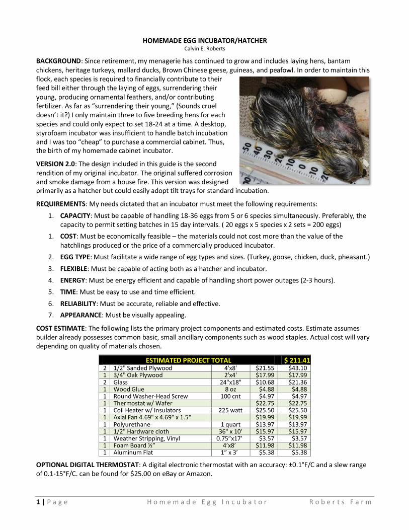
BACKGROUND: Since retirement, my menagerie has continued to grow and includes laying hens, bantam chickens, heritage turkeys, mallard ducks, Brown Chinese geese, guineas, and peafowl. In order to maintain this flock, each species is required to financially contribute to their feed bill either through the laying of eggs, surrendering their young, producing ornamental feathers, and/or contributing fertilizer. As far as “surrendering their young,” (Sounds cruel doesn’t it?) I only maintain three to five breeding hens for each species and could only expect to set 18-24 at a time. A desktop, styrofoam incubator was insufficient to handle batch incubation and I was too “cheap” to purchase a commercial cabinet. Thus, the birth of my homemade cabinet incubator.
VERSION 2.0: The design included in this guide is the second rendition of my original incubator. The original suffered corrosion and smoke damage from a house fire. This version was designed primarily as a hatcher but could easily adopt tilt trays for standard incubation.
REQUIREMENTS: My needs dictated that an incubator must meet the following requirements:
1. CAPACITY: Must be capable of handling 18-36 eggs from 5 or 6 species simultaneously. Preferably, the capacity to permit setting batches in 15 day intervals. ( 20 eggs x 5 species x 2 sets = 200 eggs)
1. COST: Must be economically feasible – the materials could not cost more than the value of the hatchlings produced or the price of a commercially produced incubator.
2. EGG TYPE: Must facilitate a wide range of egg types and sizes. (Turkey, goose, chicken, duck, pheasant.)
3. FLEXIBLE: Must be capable of acting both as a hatcher and incubator.
4. ENERGY: Must be energy efficient and capable of handling short power outages (2-3 hours).
5. TIME: Must be easy to use and time efficient.
6. RELIABILITY: Must be accurate, reliable and effective.
7. APPEARANCE: Must be visually appealing.
COST ESTIMATE: The following lists the primary project components and estimated costs. Estimate assumes builder already possesses common basic, small ancillary components such as wood staples. Actual cost will vary depending on quality of materials chosen.
ESTIMATED PROJECT TOTAL $ 211.41 2 1/2" Sanded Plywood 4'x8' $21.55 $43.10 1 3/4" Oak Plywood 2'x4' $17.99 $17.99 2 Glass 24"x18" $10.68 $21.36 1 Wood Glue 8 oz $4.88 $4.88 1 Round Washer-Head Screw 100 cnt $4.97 $4.97 1 Thermostat w/ Wafer
$22.75 $22.75
1 Coil Heater w/ Insulators 225 watt $25.50 $25.50 1 Axial Fan 4.69" x 4.69" x 1.5"
$19.99 $19.99
1 Polyurethane 1 quart $13.97 $13.97 1 1/2" Hardware cloth 36" x 10' $15.97 $15.97 1 Weather Stripping, Vinyl 0.75”x17’ $3.57 $3.57 1 Foam Board ½” 4’x8’ $11.98 $11.98 1 Aluminum Flat 1” x 3’ $5.38 $5.38
OPTIONAL DIGITAL THERMOSTAT: A digital electronic thermostat with an accuracy: ±0.1°F/C and a slew range of 0.1-15°F/C. can be found for $25.00 on eBay or Amazon.
2 | P a g e H o m e m a d e E g g I n c u b a t o r R o b e r t s F a r m
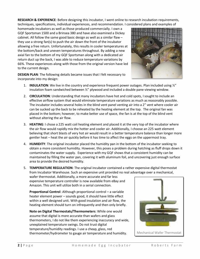
RESEARCH & EXPERIENCE: Before designing this incubator, I went online to research incubation requirements, techniques, specifications, individual experiences, and recommendation. I considered plans and examples of homemade incubators as well as those produced commercially. I own a GQF Sportsman 1500 and a Brinsea 380 and have also examined a Dickey cabinet. All follow the same good basic design as well as a similar flaw – they use a strong fan(s) to push the air down the front of the incubator allowing a free return. Unfortunately, this results in cooler temperatures at the bottom/back and uneven temperatures throughout. By adding a new axial fan to the bottom of my GQF Sportsman along with a dedicated air return duct up the back, I was able to reduce temperature variations by 66%. These experiences along with those from the original version have led to the current design.
DESIGN PLAN: The following details became issues that I felt necessary to incorporate into my design:
1. INSULATION: We live in the country and experience frequent power outages. Plan included using ½” insulation foam sandwiched between ½” plywood and included a double pane viewing window.
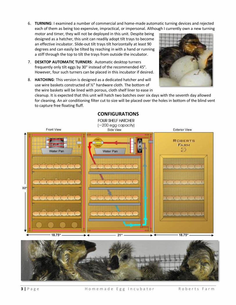
2. CIRCULATION: Understanding that many incubators have hot and cold spots, I sought to include an effective airflow system that would eliminate temperature variations as much as reasonably possible. The incubator includes several holes in the blind vent panel venting air into a 2” vent where cooler air can be sucked up the back to be reheated by the heating element at the top. The original fan was placed in the bottom; however, to make better use of space, the fan is at the top of the blind vent without altering the air flow.
3. HEATING: I chose a 225 watt coil heating element and placed it at the very top of the incubator where the air flow would rapidly mix the hotter and cooler air. Additionally, I choose an 225 watt element believing that short blasts of very hot air would result in a better temperature balance than longer more gentler heat – heat the air quickly before it has time to affect the eggs on the uppermost tray.
4. HUMIDITY: The original incubator placed the humidity pan in the bottom of the incubator seeking to obtain a more consistent humidity. However, this poses a problem during hatching as fluff drops down it contaminates the water supply. Experience with my GQF shows that a consistent humidity can be maintained by filling the water pan, covering it with aluminum foil, and uncovering just enough surface area to provide the desired humidity.
5. TEMPERATURE REGULATION: The original incubator contained a rather expensive digital thermostat from Incubator Warehouse. Such an expensive unit provided no real advantage over a mechanical, wafer thermostat. Additionally, a more accurate and far less expensive temperature controller is now available from eBay and Amazon. This unit will utilize both in a serial connection.
Proportional Control: Although proportional control – a variable heater element power – sounds good, it should have little effect within a well designed unit. With good insulation and air flow, the heating element should turn on infrequently and then only briefly.
Note on Digital Thermostats/Thermometers: While one would assume that digital is more accurate than wafers and glass thermometers, I do not like them experiencing inaccuracy and wide, unexplained temperature swings. Do not trust digital temperature/humidity readings. I use a cheap, glass, red thermometer/hydrometer to gauge air temperature and humidity.
Mechanical Wafer Thermostat
3 | P a g e H o m e m a d e E g g I n c u b a t o r R o b e r t s F a r m
6. TURNING: I examined a number of commercial and home-made automatic turning devices and rejected each of them as being too expensive, impractical, or impersonal. Although I currently own a new turning motor and timer, they will not be deployed in this unit. Despite being designed as a hatcher, this unit can readily adopt tilt trays to become an effective incubator. Slide-out tilt trays tilt horizontally at least 90 degrees and can easily be tilted by reaching in with a hand or running a stiff through the top to tilt the trays from outside the incubator.
7. DESKTOP AUTOMATIC TURNERS: Automatic desktop turners frequently only tilt eggs by 30° instead of the recommended 45°. However, four such turners can be placed in this incubator if desired.
8. HATCHING: This version is designed as a dedicated hatcher and will use wire baskets constructed of ½” hardware cloth. The bottom of the wire baskets will be lined with porous, cloth shelf liner to ease in cleanup. It is expected that this unit will hatch two batches over six days with the seventh day allowed for cleaning. An air conditioning filter cut to size will be placed over the holes in bottom of the blind vent to capture free floating fluff.
CONFIGURATIONS

4 | P a g e H o m e m a d e E g g I n c u b a t o r R o b e r t s F a r m
CAUTION: This is a very heavy incubator. Assistance will be required for assembly and moving.

5 | P a g e H o m e m a d e E g g I n c u b a t o r R o b e r t s F a r m
CAUTION: In designing this incubator, I attempted to plan every detail; however, often I do not discover specific details until the build. [I am not an engineer, architect, or draftsman.] Illustrations, measurements, and specifications should be considered rough estimates. Dry fit all pieces before cutting new pieces or assembling. Small measurement adjustments will be necessary if the plywood thickness is not exactly 1/2”.
PANEL ASSEMBLY: Individual panels may be assembled in a permanent manner using wood staples and glue.
1. Cut individual pieces according to the dimensions provided.
2. Test fit all pieces before gluing and stapling.
3. Glue furring strips to cut plywood sheet as illustrated.
4. Place insulation inside the pocket formed by the furring strips.
5. Place glue on the exposed furring strips.
6. Place the second plywood sheet on top.
7. Align all edges.
8. Staple every 6” using 1.25” staples from plywood sheet that will face inward. The top of the staple
should be slightly below the surface.
9. Fill staple holes with waterproof wood filler or compound cleaning away any excess.
10. Allow to set for 24 hours.
11. Prime all surfaces with a single, thin coat of polyurethane or desired paint.
12. Lightly sand removing any imperfections or paint drips.
13. Recoat all surfaces with a thin coat of polyurethane or desired paint.
6 | P a g e H o m e m a d e E g g I n c u b a t o r R o b e r t s F a r m
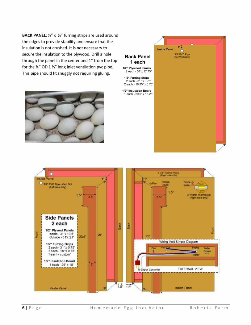
BACK PANEL: ½” x ¾” furring strips are used around
the edges to provide stability and ensure that the
insulation is not crushed. It is not necessary to
secure the insulation to the plywood. Drill a hole
through the panel in the center and 1” from the top
for the ¾” OD 1 ½” long inlet ventilation pvc pipe.
This pipe should fit snuggly not requiring gluing.
7 | P a g e H o m e m a d e E g g I n c u b a t o r R o b e r t s F a r m
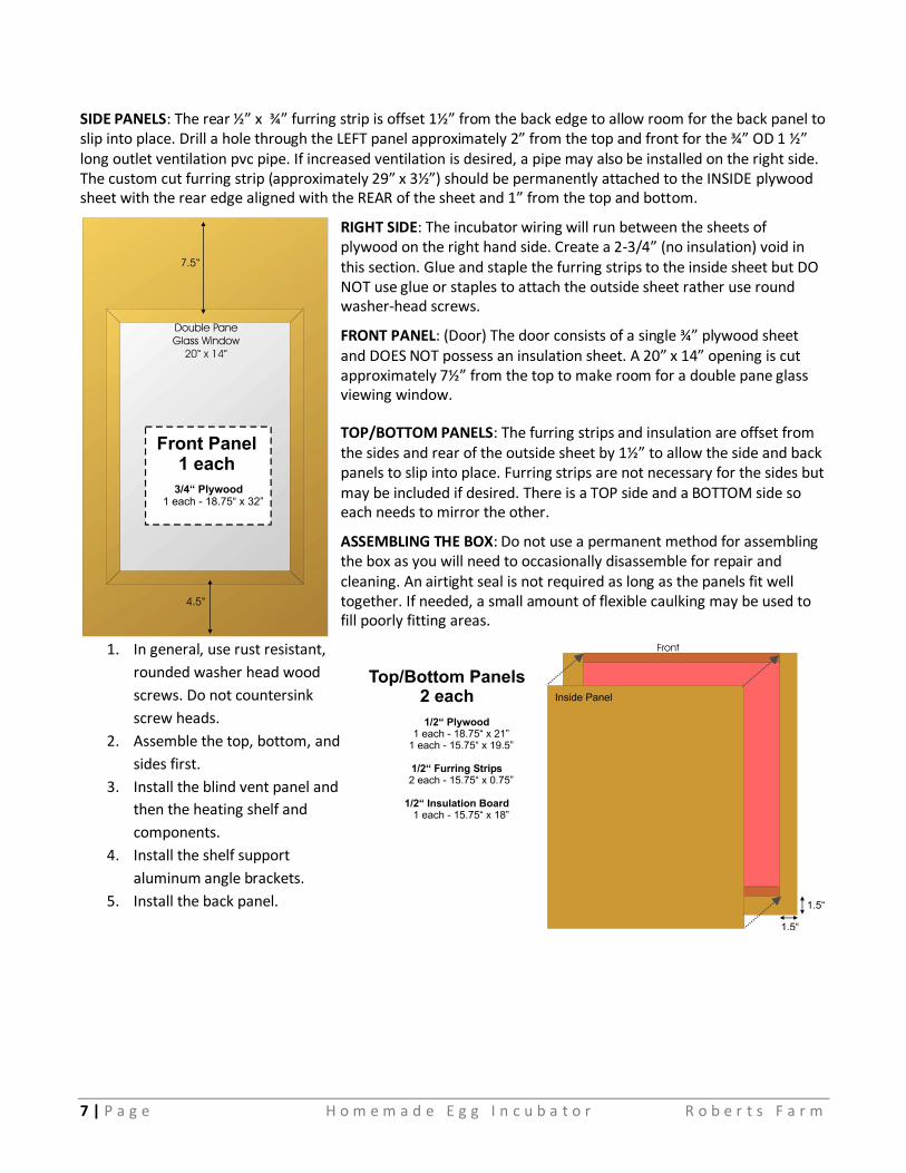
SIDE PANELS: The rear ½” x ¾” furring strip is offset 1½” from the back edge to allow room for the back panel to slip into place. Drill a hole through the LEFT panel approximately 2” from the top and front for the ¾” OD 1 ½” long outlet ventilation pvc pipe. If increased ventilation is desired, a pipe may also be installed on the right side. The custom cut furring strip (approximately 29” x 3½”) should be permanently attached to the INSIDE plywood sheet with the rear edge aligned with the REAR of the sheet and 1” from the top and bottom.
RIGHT SIDE: The incubator wiring will run between the sheets of plywood on the right hand side. Create a 2-3/4” (no insulation) void in this section. Glue and staple the furring strips to the inside sheet but DO NOT use glue or staples to attach the outside sheet rather use round washer-head screws.
FRONT PANEL: (Door) The door consists of a single ¾” plywood sheet and DOES NOT possess an insulation sheet. A 20” x 14” opening is cut approximately 7½” from the top to make room for a double pane glass viewing window.
TOP/BOTTOM PANELS: The furring strips and insulation are offset from the sides and rear of the outside sheet by 1½” to allow the side and back panels to slip into place. Furring strips are not necessary for the sides but may be included if desired. There is a TOP side and a BOTTOM side so each needs to mirror the other.
ASSEMBLING THE BOX: Do not use a permanent method for assembling the box as you will need to occasionally disassemble for repair and cleaning. An airtight seal is not required as long as the panels fit well together. If needed, a small amount of flexible caulking may be used to fill poorly fitting areas.
1. In general, use rust resistant,
rounded washer head wood
screws. Do not countersink
screw heads.
2. Assemble the top, bottom, and
sides first.
3. Install the blind vent panel and
then the heating shelf and
components.
4. Install the shelf support
aluminum angle brackets.
5. Install the back panel.
8 | P a g e H o m e m a d e E g g I n c u b a t o r R o b e r t s F a r m
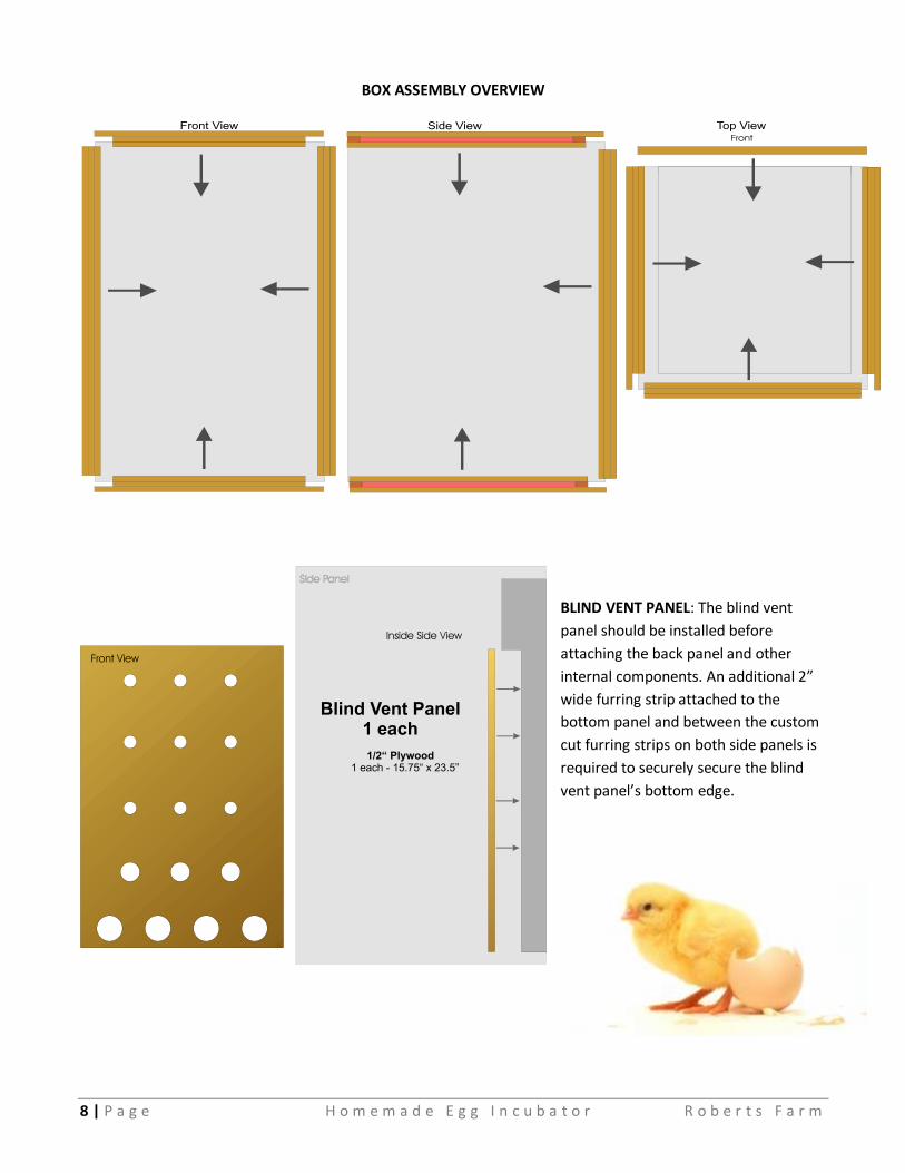
BOX ASSEMBLY OVERVIEW
BLIND VENT PANEL: The blind vent
panel should be installed before
attaching the back panel and other
internal components. An additional 2”
wide furring strip attached to the
bottom panel and between the custom
cut furring strips on both side panels is
required to securely secure the blind
vent panel’s bottom edge.
9 | P a g e H o m e m a d e E g g I n c u b a t o r R o b e r t s F a r m
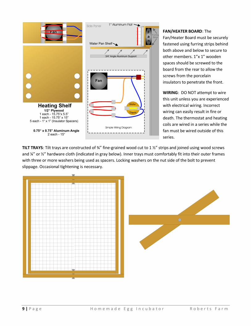
FAN/HEATER BOARD: The
Fan/Heater Board must be securely
fastened using furring strips behind
both above and below to secure to
other members. 1”x 1” wooden
spaces should be screwed to the
board from the rear to allow the
screws from the porcelain
insulators to penetrate the front.
WIRING: DO NOT attempt to wire
this unit unless you are experienced
with electrical wiring. Incorrect
wiring can easily result in fire or
death. The thermostat and heating
coils are wired in a series while the
fan must be wired outside of this
series.
TILT TRAYS: Tilt trays are constructed of ¾” fine-grained wood cut to 1 ½” strips and joined using wood screws
and ¼” or ½” hardware cloth (indicated in gray below). Inner trays must comfortably fit into their outer frames
with three or more washers being used as spacers. Locking washers on the nut side of the bolt to prevent
slippage. Occasional tightening is necessary.
10 | P a g e H o m e m a d e E g g I n c u b a t o r R o b e r t s F a r m
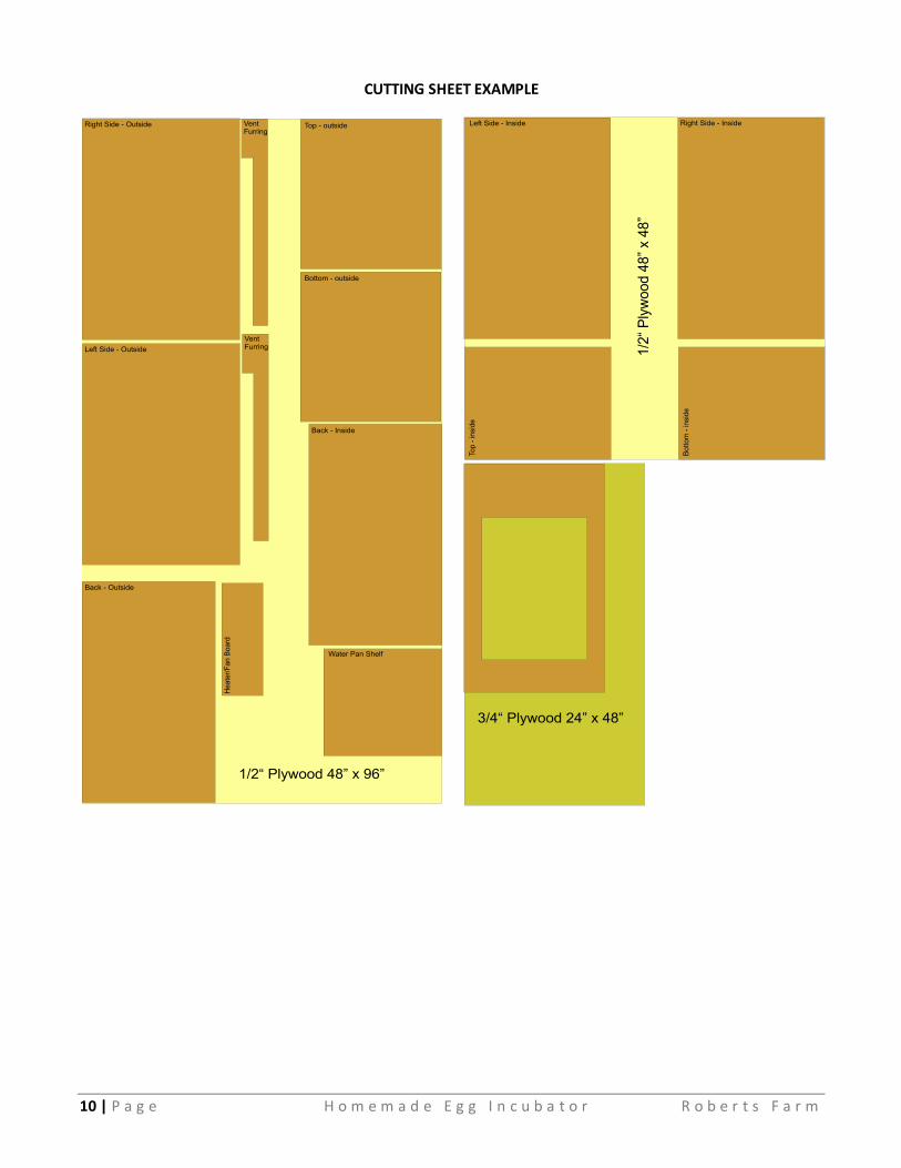
CUTTING SHEET EXAMPLE
11 | P a g e H o m e m a d e E g g I n c u b a t o r R o b e r t s F a r m
Making a Double Pane Glass Window for an Egg Incubator
NOTE: Illustrations are not to scale. Adjust measurements as needed. (I adjust as I build.)
MATERIALS:
1. Two panes of glass cut ½” (both width & length) larger than desired finished size. 2. 1”x4” hardwood/softwood board: Should match the type of wood used for the door. Should be tight
grained with no knots. Length will vary according to actual finish size. 3. Scrap ¼” plywood: will be used on the inside as a spacer. 4. Scrap ½” plywood: will be used on the inside to secure the window. 5. Wood glue: White Elmer’s glue is adequate. 6. Tube of 100% Silicon caulk. 7. Finishing nails preferably rust resistant. 8. Table saw with fence and a sharp blade.
PROCESS: I like to plan, but usually make alterations during the building stage… too many numbers become confusing. Thus, I tend to build things out of order.
3. Determine the size of the desired window. 4. Have two sheets of glass cut ½” larger (both width & length) larger than desired finished size. 5. Build the Window Frame around the size of the cut glass.
a. Cut the 1”x4” hardwood/softwood board to approximate lengths to left, right, top, and bottom necessary to frame glass. 1. I would make them several inches longer than needed. 2. Mark each piece Left, Right, Top, and Bottom.
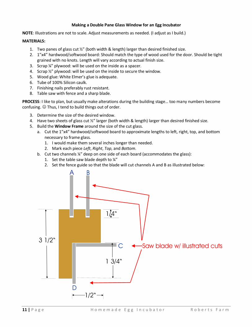
b. Cut two channels ¼” deep on one side of each board (accommodates the glass): 1. Set the table saw blade depth to ¼” 2. Set the fence guide so that the blade will cut channels A and B as illustrated below:
12 | P a g e H o m e m a d e E g g I n c u b a t o r R o b e r t s F a r m
3. These channels become the INSIDE of the frame.
c. Cut a cut-out (lap) on the inside-outer portion of the frame (Cuts C & D).
1. The full width of the frame (3 ½”) will face outside.
2. The cut-out (lap) will slip into the hole cut into the door.
d. Cut each frame section using 45 degree angles so that it snuggly frames the glass panes.
1. Be sure that cut-outs (lap) line up on the back.
2. Glue & screw the left, right, and bottom frame sections together.
3. Place a small bead of Silicone caulking into the glass channels for all three sides.
4. Slide the glass panes into place.
5. Place a small bead of Silicone caulking into the glass channels of the top side.
6. Glue & screw the top frame section.
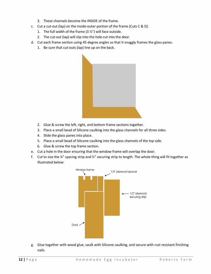
e. Cut a hole in the door ensuring that the window frame will overlap the door.
f. Cut to size the ¼” spacing strip and ½” securing strip to length. The whole thing will fit together as
illustrated below:
g. Glue together with wood glue, caulk with Silicone caulking, and secure with rust resistant finishing
nails.