HISTORIC AREA - unchartedlancaster.com
8
HISTORIC AREA
Transcript of HISTORIC AREA - unchartedlancaster.com

HISTORIC AREA
I
Lock 12 Historic Area Welcome to the Lock 12 Historic Area, one of several sites that the company has developed and maintained for public use on land surrounding the Holtwood hydroelectric plant on the Susquehanna River.
The facilities provided here for picnicking, hiking, sightseeing, cultural study and related activities are intended for your convenience and enjoyment. We are pleased that you want to use them
The Lock 12 Historic Area takes its name from one of28 lift locks constructed to overcome a difference in elevation of233 feet in the historic Susquehanna and Tidewater Canal. The canal paralleled the river for 45 miles between Wrightsville, Pa., and Havre de Grace, Md.
Built between 1836 and 1839, the canal operated from 1840 until it was abandoned in 1894. During the canal's life span, the freight barges that plied its waters carried thousands of tons of coal, lumber, iron and grain bound for Baltimore, Philadelphia and New York Some boats also carried passengers.
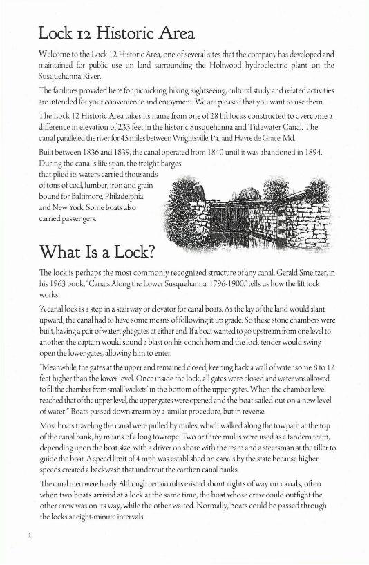
What Is a Lock? The lock is perhaps the most commonly recognized structure of any canal. Gerald Smeltzer, in his 1963 book, "Canals Along the Lower Susquehanna, 1796- 1900," tells us how the lift lock works:
"A canal lock is a step in a stairway or elevator for canal boats. As the lay of the land would slant upward, the canal had to have some means of following it up grade. So these stone chambers were built, having a pair of watertight gates at either end. Lfa boat wanted to go upstream from one level to another, the captain would sound a blast on his conch horn and the lock tender would swing open the lower gates, allowing him to enter.
"Meanwhile, the gates at the upper end remained closed, keeping back a wall of water some 8 to 12 feet higher than the lower level. Once inside the lock, all gates were closed and water was allowed to fill the chamber from small 'wickets' in the bottom of the upper gates. When the chamber level reached that of the upper level, the upper gates were opened and the boat sailed out on a new level of water." Boats passed downstream by a similar procedure, but in reverse.
Most boats traveling the canal were pulled by mules, which walked along the towpath at the top of the canal bank, by means of a long towrope. Two or three mules were used as a tandem te:un, depending upon the boat size, with a driver on shore with the team and a steersman at the tiller to guide the boat. A speed limit of 4 mph was established on canals by the state because higher speeds created a backwash that undercut the earthen canal banks.
The canal men were hardy. Although certain rules existed about rights of way on canals, often when two boats arrived at a lock at the same time, the boat whose crew could outfight the other crew was on its way, while the other waited. Nonnally, boats could be passed through the locks at eight-minute intervals.
Lock Walls Preserved Lock No. 12 was 17 feet wide, 170 feet long and had a lift capacity of8.8 feet. Its schist-stone walls, in remarkably good condition a centmy after falling into disuse, are being preserved for their educational and historical interest. Gone, however, are the hinged wooden gates that fit tightly to each end of the lock and that opened or closed to control tl1e height of the water in the lock
The walls are a reminder of the fine hand craftsmanship of construction work in the 19th century They contrast sharply in size and methods used with present building projects, as exemplified by me Norman Wood Bridge, which carries Route 3 72 across the river just south ofLock 12.
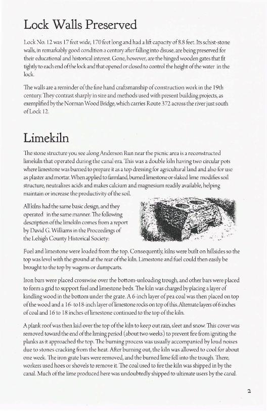
Limekiln The stone structure you see along Anderson Run near the picnic area is a reconstructed limekiln that operated during the canal era. 1l1is was a double kiln having two circular pots where limestone was burned to prepare it as a top dressing for agricultural land and also for use as plaster and mortar. When applied to f.um.land, burned limestone or slaked lime modifies soil structure, neutralizes acids and makes calcium and magnesium readily available, helping maintain or increase the productivity of the soil.
All kilns had the same basic design, and they operated in the same manner. The following description of the limekiln comes from a report by David G. Williams in the Proceedings of the Lehigh County Historical Society:
Fuel and limestone were loaded from me top. Consequently, kilns were built on hillsides so the top was level with the ground at the rear of the kiln. Limestone and fuel could then easi ly be brought to the top by wagons or dumpcarts.
Iron bars were placed crosswise over the bottom-unloading trough, and other bars were placed to form a grid to support fuel and limestone beds. The kiln was charged by placing a layer of kindling wood in tl1e bottom under the grate. A 6-inch layer of pea coal was then placed on top of the wood and a 16- to I 8-inch layer of limestone rocks on top of mis. Alternate layers of 6 inches of coal and 16 to 18 inches of limestone continued to the top of the kiln.
A plank roof was then laid over the top of the kiln to keep out rain, sleet and snow. 1l1is cover was removed toward the end of the liming period ( about two weeks) to prevent fire from igniting the planks as it approached the top. The burning process was usually accompanied by loud noises due to stones cracking from the heat. After burning out, the kiln was allowed to cool for about one week. The iron grate bars were removed, and the burned lime fell into the trough. There, workers used hoes or shovels to remove it. The coal used to fire the kiln was shipped in by the canal. Much of the lime produced here was undoubtedly shipped to ultimate users by the canal.
2

3
Sawmill Site At a site along Anderson RLIIl upstream from the limekiln, a rock foundation is all that remains of a quaint sawmill. Here, trees from nearby woodlands were cut into lumber and shipped to market on the canal. As shown on the map, the water resource of Anderson Run was tapped to provide power for operating the sawmill. \,Yater from the stream was diverted into a raceway and stored in a small millpond constructed on the hill above the sawmill. Water released from the pond in to a flume line then flowed quickly over a waterwheel at the mill, turning the large saw blade.
Lock 13 Lock 13, the next lock toward Havre de Grace, is only about 2,000 feet south of Lock 12 on property owned jointly by Holtwood, LLC and Exelon. This lock can be found by fo llowing the trail under the No rman Wood Bridge and through the woods along tl1e old towpath to Lock 13. Large trees growing in the lock are evidence that it's been abandoned for many years. Hurricane Agnes caused extensive damage to the area around Lock 13 in June 1972.
At Lock 13, you'll find another fascinating feature ofcanal constrnction. From the loop trail, you can see a 10-foot-high rock wall that had to be built in the lowland area to retain the canal and towpath. This retaining wall, typical of many along the canal, ft11ther illustrates the amount of hand craftsmanship and labor involved in cana.l construction.
In addition to the lock and retaining wal.l, foundat ions of the covered bridge, lock house and store remai n. They hint at the lifi: that existed along the canal in cl1e last century
You also can see Lock 13 from observation points along the trail. Please stay on the trail for your own safety. Please refrain from walking in the lock or along the top edge of the lock and rock wall. Your cooperation will help ensure they retain their appearances.
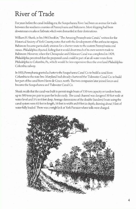
River of Trade For years before the canal-building era, the Susquehanna River had been an avenue for trade betw'een the southern counties of Pennsylvania and Baltimore. Most shipping had been downstream on arks or flatboats, which were dismantled at their destinations.
William H. Shank, in his 1965 booklet, "The Amazing Pennsylvania Canals," written for the Historical Society ofYork County, notes that with the development of the anthracite region, Baltimore became particularly anxious for a shorter route to the eastern Pennsylvania coal mines. Philadelphia objected, feeling that it would divert much of its own western trade to Baltimore. However, when the Chesapeake and Delaware Canal was completed in 1829, Philadelphia perceived that the proposed canal could be part ofan all-water route from Philadelphia to Columbia, Pa., which would be less expensive than the overl and PhiladelphiaColumbia railway.
ln 1835, Pennsylvania granted a chatter to tl1e Susquehanna Canal Co. to build a canal from Columbia to the state line. Maryland had already chartered the Tidewater Canal Co. to build her part of the canal from Havre de Grace, north. The two companies later joined forces and became the Susquehanna and Tidewater Canal Co.
Shank recaUs tl1at the canal was built to permit single boats of I SO-ton capacity or tandem boats up to 300 tons per pair to pass the locks easily. The canal channel was designed SO feet wide at water level and S ½ to 6 feet deep. Average dimensions of the double ( tandem) boats using the canal system were 65 feet in length, l 6 feet in width and 8 feet in depth, drawing about S feet of water fully loaded. There was a weigh lock at York Furnace where tolls were charged.
4
5
Lock 12 Area
SUSQUEHANNA RIVE\
LOCK , TOILETS
) j LIME .---□-□ _ _ ' [KILN
SAWMILL
!"-' ._)
PARKING
PARKING
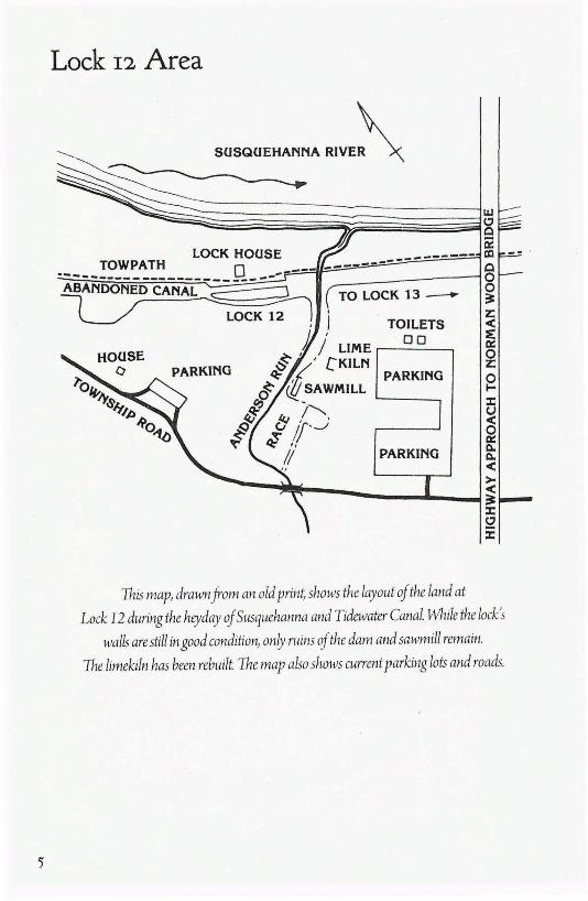
This map, drawn from an old print shows the layout of the land at
Lock 12 during the heyday of Susquehanna and Tidewater Canal. While the lock's
walls are still in good condition1 only ruins of the dam and sawmill remain.
The limekiln has been rebuilt. The map also shows current parking lots and roads.
Lock 13 Area
~ 6 C) ['II
S(JSQ(JEHANNA RIVER
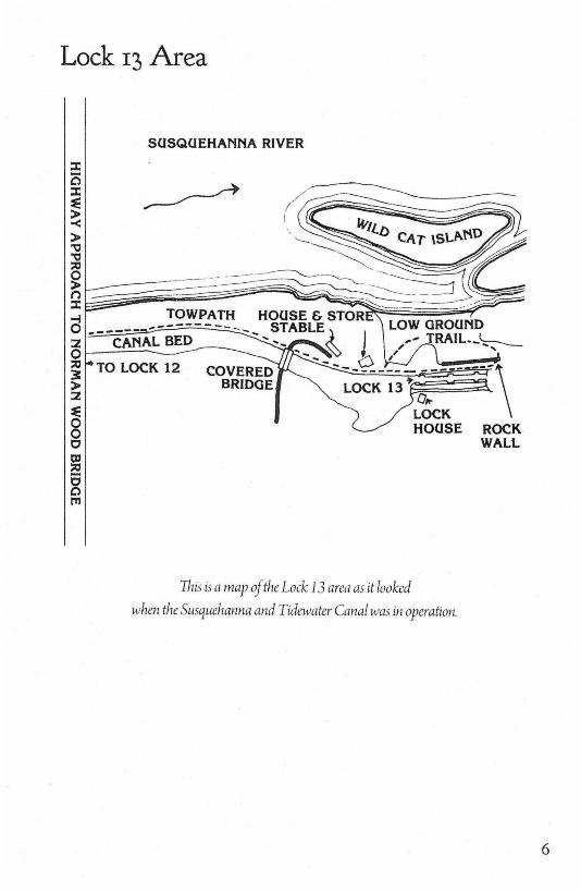
This is a map of the Lock 13 area as it looked
when the Susquehanna and Tidewater Canal was in operation.
6

Holtwood, LLC www .holtwoodhydro.com