Highly Emissive Green Perovskite Nanocrystals in a … Emissive Green Perovskite Nanocrystals in a...
6
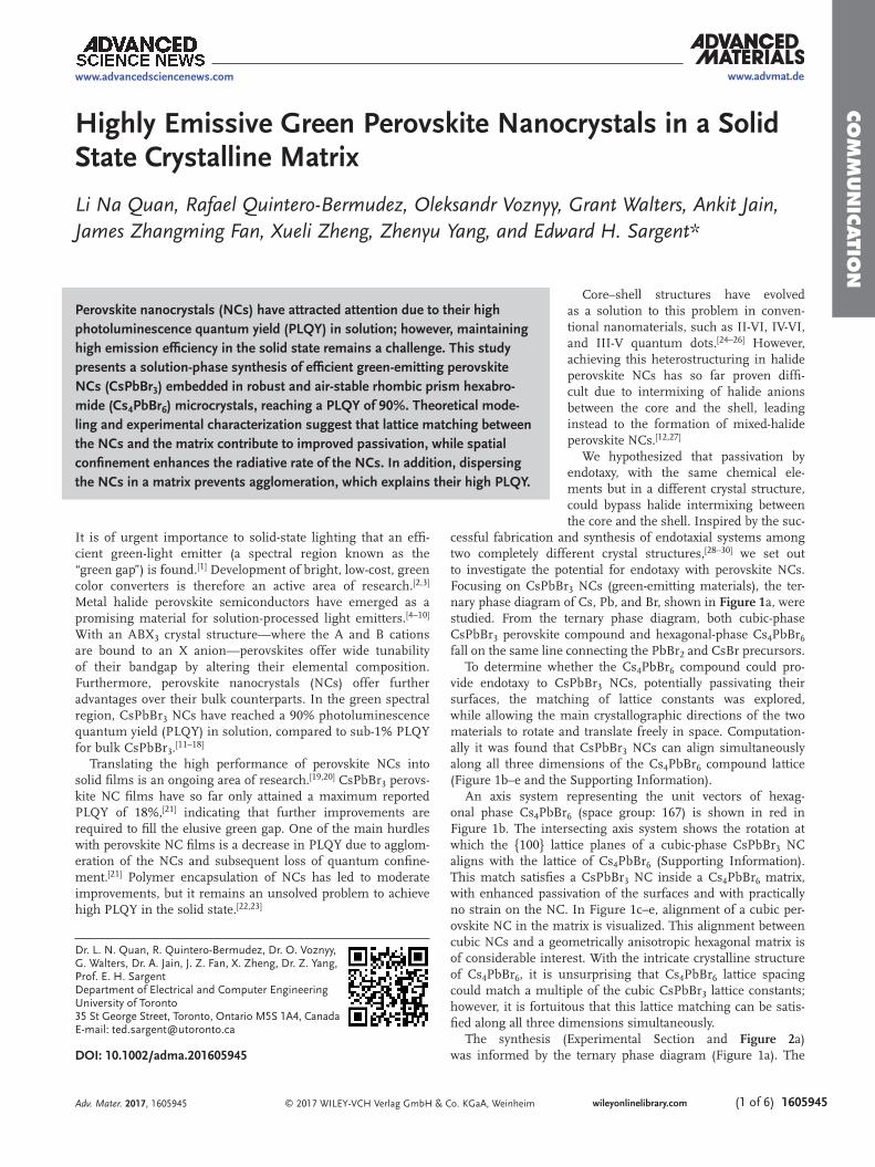
COMMUNICATION © 2017 WILEY-VCH Verlag GmbH & Co. KGaA, Weinheim wileyonlinelibrary.com (1 of 6) 1605945 Highly Emissive Green Perovskite Nanocrystals in a Solid State Crystalline Matrix Li Na Quan, Rafael Quintero-Bermudez, Oleksandr Voznyy, Grant Walters, Ankit Jain, James Zhangming Fan, Xueli Zheng, Zhenyu Yang, and Edward H. Sargent* Dr. L. N. Quan, R. Quintero-Bermudez, Dr. O. Voznyy, G. Walters, Dr. A. Jain, J. Z. Fan, X. Zheng, Dr. Z. Yang, Prof. E. H. Sargent Department of Electrical and Computer Engineering University of Toronto 35 St George Street, Toronto, Ontario M5S 1A4, Canada E-mail: [email protected] DOI: 10.1002/adma.201605945 Core–shell structures have evolved as a solution to this problem in conven- tional nanomaterials, such as II-VI, IV-VI, and III-V quantum dots. [24–26] However, achieving this heterostructuring in halide perovskite NCs has so far proven diffi- cult due to intermixing of halide anions between the core and the shell, leading instead to the formation of mixed-halide perovskite NCs. [12,27] We hypothesized that passivation by endotaxy, with the same chemical ele- ments but in a different crystal structure, could bypass halide intermixing between the core and the shell. Inspired by the suc- cessful fabrication and synthesis of endotaxial systems among two completely different crystal structures, [28–30] we set out to investigate the potential for endotaxy with perovskite NCs. Focusing on CsPbBr 3 NCs (green-emitting materials), the ter- nary phase diagram of Cs, Pb, and Br, shown in Figure 1a, were studied. From the ternary phase diagram, both cubic-phase CsPbBr 3 perovskite compound and hexagonal-phase Cs 4 PbBr 6 fall on the same line connecting the PbBr 2 and CsBr precursors. To determine whether the Cs 4 PbBr 6 compound could pro- vide endotaxy to CsPbBr 3 NCs, potentially passivating their surfaces, the matching of lattice constants was explored, while allowing the main crystallographic directions of the two materials to rotate and translate freely in space. Computation- ally it was found that CsPbBr 3 NCs can align simultaneously along all three dimensions of the Cs 4 PbBr 6 compound lattice (Figure 1b–e and the Supporting Information). An axis system representing the unit vectors of hexag- onal phase Cs 4 PbBr 6 (space group: 167) is shown in red in Figure 1b. The intersecting axis system shows the rotation at which the {100} lattice planes of a cubic-phase CsPbBr 3 NC aligns with the lattice of Cs 4 PbBr 6 (Supporting Information). This match satisfies a CsPbBr 3 NC inside a Cs 4 PbBr 6 matrix, with enhanced passivation of the surfaces and with practically no strain on the NC. In Figure 1c–e, alignment of a cubic per- ovskite NC in the matrix is visualized. This alignment between cubic NCs and a geometrically anisotropic hexagonal matrix is of considerable interest. With the intricate crystalline structure of Cs 4 PbBr 6 , it is unsurprising that Cs 4 PbBr 6 lattice spacing could match a multiple of the cubic CsPbBr 3 lattice constants; however, it is fortuitous that this lattice matching can be satis- fied along all three dimensions simultaneously. The synthesis (Experimental Section and Figure 2a) was informed by the ternary phase diagram (Figure 1a). The It is of urgent importance to solid-state lighting that an effi- cient green-light emitter (a spectral region known as the “green gap”) is found. [1] Development of bright, low-cost, green color converters is therefore an active area of research. [2,3] Metal halide perovskite semiconductors have emerged as a promising material for solution-processed light emitters. [4–10] With an ABX 3 crystal structure—where the A and B cations are bound to an X anion—perovskites offer wide tunability of their bandgap by altering their elemental composition. Furthermore, perovskite nanocrystals (NCs) offer further advantages over their bulk counterparts. In the green spectral region, CsPbBr 3 NCs have reached a 90% photoluminescence quantum yield (PLQY) in solution, compared to sub-1% PLQY for bulk CsPbBr 3 . [11–18] Translating the high performance of perovskite NCs into solid films is an ongoing area of research. [19,20] CsPbBr 3 perovs- kite NC films have so far only attained a maximum reported PLQY of 18%, [21] indicating that further improvements are required to fill the elusive green gap. One of the main hurdles with perovskite NC films is a decrease in PLQY due to agglom- eration of the NCs and subsequent loss of quantum confine- ment. [21] Polymer encapsulation of NCs has led to moderate improvements, but it remains an unsolved problem to achieve high PLQY in the solid state. [22,23] Perovskite nanocrystals (NCs) have attracted attention due to their high photoluminescence quantum yield (PLQY) in solution; however, maintaining high emission efficiency in the solid state remains a challenge. This study presents a solution-phase synthesis of efficient green-emitting perovskite NCs (CsPbBr 3 ) embedded in robust and air-stable rhombic prism hexabro- mide (Cs 4 PbBr 6 ) microcrystals, reaching a PLQY of 90%. Theoretical mode- ling and experimental characterization suggest that lattice matching between the NCs and the matrix contribute to improved passivation, while spatial confinement enhances the radiative rate of the NCs. In addition, dispersing the NCs in a matrix prevents agglomeration, which explains their high PLQY. Adv. Mater. 2017, 1605945 www.advancedsciencenews.com www.advmat.de
Transcript of Highly Emissive Green Perovskite Nanocrystals in a … Emissive Green Perovskite Nanocrystals in a...
Co
mm
un
iCatio
n
© 2017 WILEY-VCH Verlag GmbH & Co. KGaA, Weinheim wileyonlinelibrary.com (1 of 6) 1605945
Highly Emissive Green Perovskite Nanocrystals in a Solid State Crystalline Matrix
Li Na Quan, Rafael Quintero-Bermudez, Oleksandr Voznyy, Grant Walters, Ankit Jain, James Zhangming Fan, Xueli Zheng, Zhenyu Yang, and Edward H. Sargent*
Dr. L. N. Quan, R. Quintero-Bermudez, Dr. O. Voznyy, G. Walters, Dr. A. Jain, J. Z. Fan, X. Zheng, Dr. Z. Yang, Prof. E. H. SargentDepartment of Electrical and Computer EngineeringUniversity of Toronto35 St George Street, Toronto, Ontario M5S 1A4, CanadaE-mail: [email protected]
DOI: 10.1002/adma.201605945
Core–shell structures have evolved as a solution to this problem in conven-tional nanomaterials, such as II-VI, IV-VI, and III-V quantum dots.[24–26] However, achieving this heterostructuring in halide perovskite NCs has so far proven diffi-cult due to intermixing of halide anions between the core and the shell, leading instead to the formation of mixed-halide perovskite NCs.[12,27]
We hypothesized that passivation by endotaxy, with the same chemical ele-ments but in a different crystal structure, could bypass halide intermixing between the core and the shell. Inspired by the suc-
cessful fabrication and synthesis of endotaxial systems among two completely different crystal structures,[28–30] we set out to investigate the potential for endotaxy with perovskite NCs. Focusing on CsPbBr3 NCs (green-emitting materials), the ter-nary phase diagram of Cs, Pb, and Br, shown in Figure 1a, were studied. From the ternary phase diagram, both cubic-phase CsPbBr3 perovskite compound and hexagonal-phase Cs4PbBr6 fall on the same line connecting the PbBr2 and CsBr precursors.
To determine whether the Cs4PbBr6 compound could pro-vide endotaxy to CsPbBr3 NCs, potentially passivating their surfaces, the matching of lattice constants was explored, while allowing the main crystallographic directions of the two materials to rotate and translate freely in space. Computation-ally it was found that CsPbBr3 NCs can align simultaneously along all three dimensions of the Cs4PbBr6 compound lattice (Figure 1b–e and the Supporting Information).
An axis system representing the unit vectors of hexag-onal phase Cs4PbBr6 (space group: 167) is shown in red in Figure 1b. The intersecting axis system shows the rotation at which the {100} lattice planes of a cubic-phase CsPbBr3 NC aligns with the lattice of Cs4PbBr6 (Supporting Information). This match satisfies a CsPbBr3 NC inside a Cs4PbBr6 matrix, with enhanced passivation of the surfaces and with practically no strain on the NC. In Figure 1c–e, alignment of a cubic per-ovskite NC in the matrix is visualized. This alignment between cubic NCs and a geometrically anisotropic hexagonal matrix is of considerable interest. With the intricate crystalline structure of Cs4PbBr6, it is unsurprising that Cs4PbBr6 lattice spacing could match a multiple of the cubic CsPbBr3 lattice constants; however, it is fortuitous that this lattice matching can be satis-fied along all three dimensions simultaneously.
The synthesis (Experimental Section and Figure 2a) was informed by the ternary phase diagram (Figure 1a). The
It is of urgent importance to solid-state lighting that an effi-cient green-light emitter (a spectral region known as the “green gap”) is found.[1] Development of bright, low-cost, green color converters is therefore an active area of research.[2,3] Metal halide perovskite semiconductors have emerged as a promising material for solution-processed light emitters.[4–10] With an ABX3 crystal structure—where the A and B cations are bound to an X anion—perovskites offer wide tunability of their bandgap by altering their elemental composition. Furthermore, perovskite nanocrystals (NCs) offer further advantages over their bulk counterparts. In the green spectral region, CsPbBr3 NCs have reached a 90% photoluminescence quantum yield (PLQY) in solution, compared to sub-1% PLQY for bulk CsPbBr3.[11–18]
Translating the high performance of perovskite NCs into solid films is an ongoing area of research.[19,20] CsPbBr3 perovs-kite NC films have so far only attained a maximum reported PLQY of 18%,[21] indicating that further improvements are required to fill the elusive green gap. One of the main hurdles with perovskite NC films is a decrease in PLQY due to agglom-eration of the NCs and subsequent loss of quantum confine-ment.[21] Polymer encapsulation of NCs has led to moderate improvements, but it remains an unsolved problem to achieve high PLQY in the solid state.[22,23]
Perovskite nanocrystals (NCs) have attracted attention due to their high photo luminescence quantum yield (PLQY) in solution; however, maintaining high emission efficiency in the solid state remains a challenge. This study presents a solution-phase synthesis of efficient green-emitting perovskite NCs (CsPbBr3) embedded in robust and air-stable rhombic prism hexabro-mide (Cs4PbBr6) microcrystals, reaching a PLQY of 90%. Theoretical mode-ling and experimental characterization suggest that lattice matching between the NCs and the matrix contribute to improved passivation, while spatial confinement enhances the radiative rate of the NCs. In addition, dispersing the NCs in a matrix prevents agglomeration, which explains their high PLQY.
Adv. Mater. 2017, 1605945
www.advancedsciencenews.com www.advmat.de

Co
mm
un
iCati
on
© 2017 WILEY-VCH Verlag GmbH & Co. KGaA, Weinheimwileyonlinelibrary.com1605945 (2 of 6) Adv. Mater. 2017, 1605945
www.advancedsciencenews.comwww.advmat.de
Figure 1. Theoretical model of a lattice matched cubic-phase CsPbBr3 perovskite NC in a hexagonal-phase Cs4PbBr6 matrix. a) Ternary phase dia-gram of Cs, Br, and Pb, highlighting the path between precursors CsBr and PbBr2. b) Unit cell of Cs4PbBr6 with axes along which cubic perovskite matches with the matrix. c) Cut along the (001) plane of the system, with matrix atoms reduced in size in order to facilitate the observation of the perovskite inclusion in the matrix. d,e) Two different cuts along planes of cubic perovskite (direction-guided arrow colors are consistent with those shown in (b).
Figure 2. Synthesis of perovskite CsPbBr3-in-Cs4PbBr6 microcrystals manifesting high PLQY. a) Graphical representation of the synthesis. b) Photo-luminescence emitted and (c) PLQY of materials resulting from different ratios of CsBr and PbBr2.

Co
mm
un
iCatio
n
© 2017 WILEY-VCH Verlag GmbH & Co. KGaA, Weinheim wileyonlinelibrary.com (3 of 6) 1605945
ternary phase diagram (often called a Gibbs triangle) highlights that various mixtures of the CsBr and PbBr2 precursors can produce different proportions of Cs4PbBr6 and CsPbBr3, with no intermediate phases. To overcome the different solubility of PbBr2 and CsBr in polar solvents, aprotic dimethyl sulfoxide (DMSO) solvent was used for dissolving PbBr2, and protic H2O solvent was used for CsBr. Precise control of the DMSO/H2O ratio was used to precipitate crystals in the mixed H2O-DMSO solution, and the precursor ratio was used to control the final product composition. A precursor ratio (CsBr/PbBr2) of 1 leads to CsPbBr3 microcrystals, along with some unused precursors (Figure S5, Supporting Information). As long as the ratio of the precursors was kept above 1, the synthesis resulted in a highly emissive compound (Figure S17, Supporting Information).
A red-shift in photoluminescence (PL) wavelength of the composite material, from 510 to 520 nm, was found as the ratio of CsBr/PbBr2 was increased. This is consistent with the NCs size dependent bandgap; a result of quantum confinement (Figure 2b). The PLQY also varied with precursor concentra-tion (Figures 2c); whereby, the PLQY reached a maximum of 92% at a CsBr/PbBr2 ratio of 8—a significant advance over the previous maximum (61%), which was achieved with polyhedral oligomeric silsesquioxane encapsulation.[22]
Scanning electron microscopy (SEM) images of the resulting microcrystals are shown in Figure 3a. The forma-tion of rhombic prisms agrees with Cs4PbBr6 compound as a matrix. Powder X-ray diffraction (XRD) (Figure 3b) confirms the coexistence of perovskite and hexabromide compounds
Adv. Mater. 2017, 1605945
www.advancedsciencenews.com www.advmat.de
Figure 3. Identification and characterization of a hybrid material compound. a) SEM image of the perovskite-in-hexabromide compound. b) XRD spectra of a CsPbBr3-in-Cs4PbBr6 crystal. c) Processed ICP-AES data showing the ratio of the compounds. d) Theoretical model for the material with various cubic perovskite inclusions in each rhombic prism matrix. e) High-resolution transmission electron microscopy (HRTEM) image of a CsPbBr3-in-Cs4PbBr6 crystal, with an inset showing fast Fourier transform (FFT) of a HRTEM image. f) Selected area electrond diffraction (SAED) pattern of a CsPbBr3-in-Cs4PbBr6 crystal, color-coded to identify the compounds. Peaks without color-coding are peaks where both phases overlap.

Co
mm
un
iCati
on
© 2017 WILEY-VCH Verlag GmbH & Co. KGaA, Weinheimwileyonlinelibrary.com1605945 (4 of 6)
in the material system. Wide area compositional SEM imaging (Figures S2–S4, Supporting Information) and corre-sponding energy-dispersive X-ray spectroscopy (EDS) mapp ing (Figures S13–S15, Supporting Information) confirm the pres-ence of a single phase; arguing against the possibility that CsPbBr3 and Cs4PbBr6 are present as separate bulk phases. The XRD results indicate more matrix than NCs (i.e., smaller pure-perovskite peaks). An approximate value of the ratio of CsPbBr3 to Cs4PbBr6 is determined by measuring the Cs to Pb atomic ratio using inductively coupled plasma atomic emis-sion spectrometry (ICP-AES) (Figure S2, Supporting Infor-mation), from which a ratio between CsPbBr3 to Cs4PbBr6 is deduced (Figure 3c).
A detailed material structure emerges from aggregate anal-ysis of the PL, SEM, XRD, ICP-AES, and theoretical phase matching between perovskite NCs and Cs4PbBr6 (Figure 3d)—rhombic prisms of Cs4PbBr6 that contain small cubic CsPbBr3 NCs (≈10 nm dimensions) aligned to the lattice of the matrix. The dimensions of the rhombic prisms range from 4–10 µm. It is possible that micrometric CsPbBr3 impurities are also present in the admixture; however, high PLQY values were measured (which would decrease in the presence of bulk-like CsPbBr3) that were not noticed in SEM imaging (Figures S2–S4, Supporting Information), therefore, it is unlikely that these impurities would considerably affect the measured optical properties. Furthermore, the material shows stable light emis-sion, with very little degradation after a month of storage in air (Figure S18, Supporting Information).
Transmission electron microscopy (TEM), along with SAED, offers the most direct and convincing corroboration of the model in Figure 3d. As TEM could not be used to measure the microcrystal due to its large dimensions, the microcrystal was crushed using a mortar and TEM was performed on thin chips of the crystal. Figure 3e shows a resulting TEM image, where showing a characteristic Cs4PbBr6 lattice spacing of 3.4 ± 0.1 Å, and a region with a much larger lattice spacing of 13.2 ± 0.1 Å, representing a Moiré fringe pattern resulting from the beating of two overlapping lattice fringes. Mixing of the measured lat-tice of the matrix (red) with the lattice of the NC (≈2.94 Å)[31] in the Moiré equation yields a pattern spacing consistent with experimental observations (in blue):
210 3AMoire
NC2
Matrix NC
dd
d d( )=
−= ±
°
(1)
The size in the region of interest also matches the dimen-sions of the expected NC. The SAED results evidence the coex-istence of CsPbBr3 and Cs4PbBr6 within the microcrystal. The pattern on Figure 3f shows peaks of both phases after an elec-tron beam has diffracted off a single microcrystal chip. The dif-ference in SAED patterns between regions with and without NCs can be identified in Figure S12 (Supporting Informa-tion), strongly corroborating the existence of perovskite NCs inside the microcrystals of Cs4PbBr6. Further TEM images are included in Figures S10 and S11 (Supporting Information).
A CsBr/PbBr2 precursor ratio of 8 yields microcrystals that exhibit the highest PLQY, due to sufficient spatial separation between their cubic perovskite inclusions, resulting in the best passivation of the NC surface. At lower CsBr/PbBr2 ratios, a decrease in PLQY can be attributed to the growing size of NCs, which is indicated by a red-shift in PL. These larger NCs are bulk-like, therefore exhibiting a loss in quantum confinement and a decrease in PLQY due to higher exciton dissociation. On the other side of the optimum, at small amounts of PbBr2, NC growth is impeded, leading to smaller, nonuniform NCs high in defects (Figure 2b). As the amount of PbBr2 precursor is fur-ther reduced (beyond a CsBr/PbBr2 ratio of 20), the microcrys-tals become smaller, leaving a significant amount of unreacted CsBr. At this point, there is very little CsPbBr3 and also little of the passivating Cs4PbBr6 matrix.
The wide bandgap matrix allows for direct photoexcitation of the NC inclusions. Photoluminescence excitation (PLE) spectra of NC emission at 515 nm, and matrix emission at 375 nm,[32] are plotted in Figure 4a. Notably, there is a sharp dip at ≈310 nm, where light is fully absorbed by the matrix and does not reach the NCs. In this region, the Cs4PbBr6 matrix exhibits a sharp peak in the absorption spectrum.[33]
PL decay measurements were performed on perovskite NCs in the matrix compound, yielding the traces shown in Figure 4b. Multiexponential functions fit these decay traces, with the values listed in Table S19 (Supporting Information). With similar PL lifetimes to those of colloidal CsPbBr3 perovs-kite NCs,[13,34,35] transient photophysics further evidences that
Adv. Mater. 2017, 1605945
www.advancedsciencenews.comwww.advmat.de
Figure 4. Photophysical behavior of the CsPbBr3-in-Cs4PbBr6 material. a) Normalized PLE spectra of the perovskite NCs at 515 nm and the matrix at 375 nm. b) PL decay for crystals with different ratios of CsBr to PbBr2.

Co
mm
un
iCatio
n
© 2017 WILEY-VCH Verlag GmbH & Co. KGaA, Weinheim wileyonlinelibrary.com (5 of 6) 1605945
these NCs are responsible for the high PLQY emission. The PL lifetimes were further used to compute radiative lifetimes (Table S19, Supporting Information), evidencing an increase in radiative lifetime as the size of the NC is increased, and approaching a maximal value for the bulk-like perovskite micro-crystals produced with a CsBr/PbBr2 ratio of 1. This finding agrees with the material model, exhibiting a dramatic increase in radiative lifetime due to an increase in exciton dissociation as the size of a NC is increased into the bulk-like domain.
The synthesis of cubic CsPbBr3 perovskite NCs in robust and air-stable rhombic prism Cs4PbBr6 microcrystals enables high emission efficiency in the solid state (92% PLQY). A model informed by experimental characterization and computational evidence of lattice-matching between cubic CsPbBr3 NCs and a Cs4PbBr6 matrix is proposed. Powder XRD confirms the coex-istence of perovskite NCs and the matrix. SEM imaging and PL confirmed the shape and size of the crystallites. Compound ratios were estimated from ICP-AES measurements. TEM imaging and SAED patterns provide conclusive evidence in support of the material model. Photophysical studies, including PL decay and PLE spectra, corroborated the model. In sum, all of the experimental characterizations agreed with the picture of endotaxy of perovskite NCs with a Cs4PbBr6 matrix.
Experimental SectionSynthesis of Bulk Perovskite NCs in Cs4PbBr6: 1–0.001 m (depending
on the ratio of precursors) of PbBr2 (99.9%, Alfa Aesar) was dissolved in 1 mL DMSO (99.9%, Aldrich). At the same time, 1 m of CsBr (99.999%, Aldrich) was dissolved in 300 µL H2O (deionized water). CsBr/H2O solution was then slowly injected into the PbBr2/DMSO solution and stirred at room temperature in air atmosphere for 30 min to 2 h (depending on the concentration of PbBr2). After bright green precipitates formed in the mixed solution, crystals were centrifugated at 5000 rpm and washed with toluene, followed by drying under vacuum.
Fabrication of Film Perovskite NCs in Cs4PbBr6: Perovskite NCs in Cs4PbBr6 precursor solution were prepared via the same method described above, but the concentration of PbBr2 was fixed to 0.1 m. The series of precursor solution was then spin-coated on the glass substrate, followed by annealing, for atomic force microscopy (AFM) and transient absorption (TA) measurements.
Photoluminescence Measurements (Decay, Emission Spectroscopy, and PLQY): All PL measurements were done with a Horiba Fluorolog time correlated single photon counting system with a single grating spectrometer and photomultiplier tube detector. Steady state PL and PLE measurements were done using monochromatized light from a xenon lamp as the excitation source. Transient measurements used a laser diode (λ = 375 nm) as the excitation source. The time resolution, according to the instrument response function, is Δt ≈ 0.13 ns. The standard published method for measuring quantum yields[36] was used with a Quanta-Phi integrating sphere. Excitation and emission intensities were measured in empty-sphere, direct illumination, and indirect illumination configurations. Light was coupled between the Fluorolog system and the sphere with optical fiber bundles. The detector and integrating sphere were corrected for spectral variance using a calibrated white light source.
Transient Absorption Spectroscopy: Femtosecond laser pulses of 1030 nm generated by a Yb:KGW laser at a 5 kHz repetition rate (Light Conversion, Pharos) passed through an optical parametric amplifier (Light Conversion, Orpheus) with the second harmonic of the signal pulse selected for 400 nm light. The latter served as the pump pulse, whereas the probe pulse was generated by focusing the initial 1030 nm pulse into a sapphire crystal, resulting in a white-light
continuum (Ultrafast, Helios). With a temporal resolution of the system of ≈350 fs, each time step meant delaying the probe pulse with respect to the pump, with time steps increasing exponentially. Every other pump pulse was blocked with a chopper in order to determine the ΔOD. After going through a grating spectrograph, the pulses were measured by means of a charge-coupled device (Ultrafast, Helios). Multiple scans were taken for each sample at each power, and the average of these scans was used. The traces were fitted to the convolution of the instrument response and a sum of the exponential decays.
XRD: The XRD measurements were collected at the MAX Diffraction Facility at McMaster University, using a Bruker Smart6000 CCD area detector with a Bruker 3-circle D8 goniometer, a Rigaku RU200 Cu αK rotating anode, and Göebel cross-coupled parallel focusing mirrors. Bisecting angle scans were performed with a 300 s frame exposure, a detector distance of 16.740 cm, and an X-ray beam at 90 mA and 50 kV.
Inductively Coupled Plasma Atomic Emission Spectrometry: The atomic composition of samples was determined using ICP-AES, with the Perkin Elmer Optima 7300DV. 1, 10, 100, 1000 ppm Pb and Cs were used as standards for the calibration. The perovskites in hexabromide samples were dissolved in 10% HCl before ICP-AES characterization.
Supporting InformationSupporting Information is available from the Wiley Online Library or from the author.
AcknowledgementsL.N.Q. and R.Q.-B. contributed equally to this work. The authors wish to acknowledge R. Comin, R. Sabatini, and S. Hoogland for fruitful discussions and feedback in presenting the work. Furthermore, the authors thank Dr. Jim Britten for his help in performing XRD measurements, and OCCAM for their assistance, as well as the maintenance and availability of electron microscopy equipment. Density functional theory calculations were performed on the IBM BlueGene Q supercomputer with support from the Southern Ontario Smart Computing Innovation Platform.
Received: November 3, 2016Revised: January 11, 2017
Published online:
[1] J.-L. Liu, J.-L. Zhang, G.-X. Wang, C.-L. Mo, L.-Q. Xu, J. Ding, Z.-J. Quan, X.-L. Wang, S. Pan, C.-D. Zheng, X.-M. Wu, W.-Q. Fang, F.-Y. Jiang, Chin. Phys. B 2015, 24, 067804.
[2] C. Wetzel, T. Detchprohm, Proc. SPIE 2011, 8123, 812308.[3] T. J. Miller, M. A. Haase, X. Sun, B. Hao, J. Zhang, T. L. Smith,
T. Ballen, J. Xie, A. S. Barnes, F. Kecman, J. Yang, J. Thielen, C. A. Leatherdale, R. Wirth, A. Biebersdorf, K. Engl, S. Groetsch, Proc. SPIE – Int. Soc. Opt. Eng. 2010, 7617, 76171A.
[4] H. C. Yoon, H. Kang, S. Lee, J. H. Oh, H. Yang, Y. R. Do, ACS Appl. Mater. Interfaces 2016, 8, 18189.
[5] S. Pathak, N. Sakai, F. W. R. Rivarola, S. D. Stranks, J. Liu, G. E. Eperon, C. Ducati, K. Wojciechowski, J. T. Griffiths, A. A. Haghighirad, A. Pellaroque, R. H. Friend, H. J. Snaith, Chem. Mater. 2015, 27, 8066.
[6] J. Wang, N. Wang, Y. Jin, J. Si, Z. K. Tan, H. Du, L. Cheng, X. Dai, S. Bai, H. He, Z. Ye, M. L. Lai, R. H. Friend, W. Huang, Adv. Mater. 2015, 27, 2311.
[7] H. Cho, S.-H. Jeong, M.-H. Park, Y.-H. Kim, C. Wolf, C.-L. Lee, J. H. Heo, A. Sadhanala, N. Myoung, S. Yoo, S. H. Im, R. H. Friend, T.-W. Lee, Science 2015, 350, 1222.
Adv. Mater. 2017, 1605945
www.advancedsciencenews.com www.advmat.de

Co
mm
un
iCati
on
© 2017 WILEY-VCH Verlag GmbH & Co. KGaA, Weinheimwileyonlinelibrary.com1605945 (6 of 6)
[8] M. Saliba, S. M. Wood, J. B. Patel, P. K. Nayak, J. Huang, J. A. Alexander-Webber, B. Wenger, S. D. Stranks, M. T. Hörantner, J. T. W. Wang, R. J. Nicholas, L. M. Herz, M. B. Johnston, S. M. Morris, H. J. Snaith, M. K. Riede, Adv. Mater. 2016, 28, 923.
[9] B. R. Sutherland, S. Hoogland, M. M. Adachi, C. T. O. Wong, E. H. Sargent, ACS Nano 2014, 8, 10947.
[10] B. R. Sutherland, E. H. Sargent, Nat. Photonics 2016, 10, 295.[11] C. C. Stoumpos, C. D. Malliakas, J. A. Peters, Z. Liu, M. Sebastian,
J. Im, T. C. Chasapis, A. C. Wibowo, D. Y. Chung, A. J. Freeman, B. W. Wessels, M. G. Kanatzidis, Cryst. Growth Des. 2013, 13, 2722.
[12] Q. A. Akkerman, V. D’Innocenzo, S. Accornero, A. Scarpellini, A. Petrozza, M. Prato, L. Manna, J. Am. Chem. Soc. 2015, 137, 10276.
[13] L. Protesescu, S. Yakunin, M. I. Bodnarchuk, F. Krieg, R. Caputo, C. H. Hendon, R. X. Yang, A. Walsh, M. V. Kovalenko, Nano Lett. 2015, 15, 3692.
[14] G. Rainoì, G. Nedelcu, L. Protesescu, M. I. Bodnarchuk, M. V. Kovalenko, R. F. Mahrt, T. Stöferle, ACS Nano 2016, 10, 2485.
[15] J. De Roo, M. Ibáñez, P. Geiregat, G. Nedelcu, W. Walravens, J. Maes, J. C. Martins, I. Van Driessche, M. V. Kovalenko, Z. Hens, ACS Nano 2016, 10, 2071.
[16] A. Swarnkar, R. Chulliyil, V. K. Ravi, M. Irfanullah, A. Chowdhury, A. Nag, Angew. Chem., Int. Ed. 2015, 54, 15424.
[17] Y. Hassan, Y. Song, R. D. Pensack, A. I. Abdelrahman, Y. Kobayashi, M. A. Winnik, G. D. Scholes, Adv. Mater. 2016, 28, 566.
[18] S. Bai, Z. Yuan, F. Gao, J. Mater. Chem. C 2016, 4, 3898.[19] X. Zhang, H. Lin, H. Huang, C. Reckmeier, Y. Zhang, W. C. H. Choy,
A. L. Rogach, Nano Lett. 2016, 16, 1415.[20] J. Song, J. Li, X. Li, L. Xu, Y. Dong, H. Zeng, Adv. Mater. 2015, 27,
7162.[21] Y. Kim, E. Yassitepe, O. Voznyy, R. Comin, G. Walters, X. Gong,
P. Kanjanaboos, A. F. Nogueira, E. H. Sargent, ACS Appl. Mater. Interfaces 2015, 7, 25007.
[22] H. Huang, B. Chen, Z. Wang, T. F. Hung, A. Susha, H. Zhong, A. Rogach, C. Sci, H. Huang, B. Chen, Z. Wang, T. F. Hung, A. S. Susha, H. Zhong, A. L. Rogach, Chem. Sci. 2016, 7, 5699.
[23] M. Meyns, M. Perálvarez, A. Heuer-Jungemann, W. Hertog, M. Ibáñez, R. Nafria, A. Genç, J. Arbiol, M. V. Kovalenko, J. Carreras, A. Cabot, A. G. Kanaras, ACS Appl. Mater. Interfaces 2016, 8, 19579.
[24] E. Ryu, S. Kim, E. Jang, S. Jun, H. Jang, B. Kim, S. W. Kim, Chem. Mater. 2009, 21, 573.
[25] S. A. Ivanov, A. Piryatinski, J. Nanda, S. Tretiak, K. R. Zavadil, W. O. Wallace, D. Werder, V. I. Klimov, J. Am. Chem. Soc. 2007, 129, 11708.
[26] G. E. Cragg, A. L. Efros, Nano Lett. 2010, 10, 313.[27] G. Nedelcu, L. Protesescu, S. Yakunin, M. I. Bodnarchuk,
M. J. Grotevent, M. V. Kovalenko, Nano Lett. 2015, 15, 5635.[28] L. D. Zhao, J. He, S. Hao, C. I. Wu, T. P. Hogan, C. Wolverton,
V. P. Dravid, M. G. Kanatzidis, J. Am. Chem. Soc. 2012, 134, 16327.[29] K. Biswas, J. He, Q. Zhang, G. Wang, C. Uher, V. P. Dravid,
M. G. Kanatzidis, Nat. Chem. 2011, 3, 160.[30] Z. Ning, X. Gong, R. Comin, G. Walters, F. Fan, O. Voznyy,
E. Yassitepe, A. Buin, S. Hoogland, E. H. Sargent, Nature 2015, 523, 324.
[31] M. Rodová, J. Brožek, J. Therm. Anal. 2003, 71, 667.[32] M. Nikl, E. Mihokova, K. Nitsch, F. Somma, C. Giampaolo,
G. P. Pazzi, P. Fabeni, S. Zazubovich, Chem. Phys. Lett. 1999, 306, 280.
[33] S. Kondo, K. Amaya, T. Saito, J. Phys. Condens. Matter 2002, 14, 2093.
[34] N. S. Makarov, S. Guo, O. Isaienko, W. Liu, I. Robel, V. I. Klimov, Nano Lett. 2016, 16, 2349.
[35] F. Hu, H. Zhang, C. Sun, C. Yin, B. Lv, C. Zhang, W. W. Yu, X. Wang, Y. Zhang, M. Xiao, ACS Nano 2015, 9, 12410.
[36] J. C. de Mello, H. F. Wittmannn, R. H. Friend, Adv. Mater. 1997, 9, 230.
Adv. Mater. 2017, 1605945
www.advancedsciencenews.comwww.advmat.de