High Performance DSP/FPGA controller for implementation of ...
6
High Performance DSP/FPGA Controller for Implementation of HIT/DLR Dexterous Robot Hand P. He, M.H. Jin, L. Yang, R. Wei, Y.W. Liu, H.G. Cai Robot Research Institute Harbin Institute of Technology (HIT) 150001, Harbin, P.R. China [email protected] H. Liu, N. Seitz, J. Butterfass, G. Hirzinger Institute of Robotics and Mechatronics German Aerospace Center, DLR 82230, Wessling, Germany [email protected] Abstract- The paper presents hardware and software architectures of the HIT/DLR Hand. The hand has four identical fingers and an extra degree of freedom (d.o.f) for palm. In each finger, there is a re-configurable Field Programmable Gate Array (FPGA) for data acquisition, Brushless DC (BLDC) motors control and communication with palm's FPGA by Point-to-Point Serial Communication (PPSeCo). The kernel of the hardware system is a PCI-based high speed floating-point Digital Signal Processor (DSP) for data processing, and FPGA for high speed (up to 25Mbps) real-time serial communication with the palm's FPGA. In order to achieve high modularity and reliability of the hand, a fully mechatronic integration and analog signals in-situ digitalization philosophy are implemented to minimize the dimension, number of the cables (5 cables including power supply) and protect data communication from outside disturbances. Furthermore, according to the hardware architecture of the hand, a hierarchical software architecture has been established to perform all data processing and control of the hand. The software structure provides basic Application Programming Interface (API) functions and skills to access all hardware resources for data acquisition, computation and tele- operation. Index Terms - dexterous robot hand; DSP; FPGA; modular I. INTRODUCTION In past years, research on anthropomorphic robot hands has grown to be one of the most important development fields in robotics. Some famous hands, such as Robonaut hand of NASA[I] and DLR Hand I[2] and II[3], were developed. These hands generously are equipped with multiple sensors and have features of high-degree-integration modularity. They can realize many object operations through learning human's behaviors. At the same time, the application algorithms and demands for hand control have increased, that make the development of hand's hardware and software more difficult. The electronic hardware architecture influences reliability and stability of the hand, at the same time it affects modularity of the mechanical architecture in some way. The present control algorithm of multi-fingered robot hand has raised higher requirements for multi-channel signal acquisition, fast data procession and so on. In order to realize robust low-level finger control and multi-finger stable grasping strategy, the hardware and software of the whole system should be capable of high-speed information acquisition and data processing, fast computation, stable communication, and great data/program memory, etc. In the last few years, the most advanced digital technologies were introduced into robot control applications: FPGA and DSP. The emergence of FPGA provides a flexible and feasible approach for control system designer to design quality services in a faster time frame and at lower costs than ever before. FPGA makes it possible to define the user programmable hardware subsystem that can be easily reloaded and modified on-line. DSP is a type of flexible and reliable microprocessor - one that is incredibly fast and powerful, it can process data in real time, its real-time capability and high- speed computing architecture is an optimal alternative for sophisticated control algorithms. So, the integration of FPGA and DSP can perform a lot of computing-intensive and time- critical tasks such as information acquisition and data procession in robot control applications [4]. The recently developed DLR dexterous robot hands provide an excellent platform to investigate different grasping strategies. The DLR Hand I was controlled by a multi- processor system that consisted of global hand controller and local finger controller. The two levels performed data communication via SERCOS (SErial Real time i!!iiiiiiiiiiiiiiiiiiiiiiiiii~i~iiiii!i!i!~iiiii~i~!~i~iii~i~i~i~i~i~iii~iii~i~i~i~!~ Fig. 1 The HIT/DLRhand
Transcript of High Performance DSP/FPGA controller for implementation of ...
High Performance DSP/FPGA Controller for Implementation of HIT/DLR Dexterous Robot Hand
P. He, M.H. Jin, L. Yang, R. Wei, Y.W. Liu, H.G. Cai
Robot Research Institute Harbin Institute of Technology (HIT)
150001, Harbin, P.R. China
H. Liu, N. Seitz, J. Butterfass, G. Hirzinger
Institute of Robotics and Mechatronics German Aerospace Center, DLR
82230, Wessling, Germany
A b s t r a c t - The paper presents hardware and software architectures of the HIT/DLR Hand. The hand has four identical fingers and an extra degree of freedom (d.o.f) for palm. In each finger, there is a re-configurable Field Programmable Gate Array (FPGA) for data acquisition, Brushless DC (BLDC) motors control and communication with palm's FPGA by Point-to-Point Serial Communication (PPSeCo). The kernel of the hardware system is a PCI-based high speed floating-point Digital Signal Processor (DSP) for data processing, and FPGA for high speed (up to 25Mbps) real-time serial communication with the palm's FPGA. In order to achieve high modularity and reliability of the hand, a fully mechatronic integration and analog signals in-situ digitalization philosophy are implemented to minimize the dimension, number of the cables (5 cables including power supply) and protect data communication from outside disturbances. Furthermore, according to the hardware architecture of the hand, a hierarchical software architecture has been established to perform all data processing and control of the hand. The software structure provides basic Application Programming Interface (API) functions and skills to access all hardware resources for data acquisition, computation and tele- operation.
Index Terms - dexterous robot hand; DSP; FPGA; modular
I. INTRODUCTION
In past years, research on anthropomorphic robot hands has grown to be one of the most important development fields in robotics. Some famous hands, such as Robonaut hand of NASA[I] and DLR Hand I[2] and II[3], were developed. These hands generously are equipped with multiple sensors and have features of high-degree-integration modularity. They can realize many object operations through learning human's behaviors. At the same time, the application algorithms and demands for hand control have increased, that make the development of hand's hardware and software more difficult. The electronic hardware architecture influences reliability and stability of the hand, at the same time it affects modularity of the mechanical architecture in some way. The present control algorithm of multi-fingered robot hand has raised higher requirements for multi-channel signal acquisition, fast data procession and so on. In order to realize robust low-level finger control and multi-finger stable grasping strategy, the hardware and software of the whole system should be capable of high-speed information acquisition and data processing, fast
computation, stable communication, and great data/program memory, etc.
In the last few years, the most advanced digital technologies were introduced into robot control applications: FPGA and DSP. The emergence of FPGA provides a flexible and feasible approach for control system designer to design quality services in a faster time frame and at lower costs than ever before. FPGA makes it possible to define the user programmable hardware subsystem that can be easily reloaded and modified on-line. DSP is a type of flexible and reliable microprocessor - one that is incredibly fast and powerful, it can process data in real time, its real-time capability and high- speed computing architecture is an optimal alternative for sophisticated control algorithms. So, the integration of FPGA and DSP can perform a lot of computing-intensive and time- critical tasks such as information acquisition and data procession in robot control applications [4].
The recently developed DLR dexterous robot hands provide an excellent platform to investigate different grasping strategies. The DLR Hand I was controlled by a multi- processor system that consisted of global hand controller and local finger controller. The two levels performed data communication via SERCOS (SErial Real time
i!!iiiiiiiiiiiiiiiiiiiiiiiiii~i~iiiii!i!i!~iiiii~i~!~i~iii~i~i~i~i~i~iii~iii~i~i~i~!~i~iii~i~iiiii~!ii!ii~ii~ii~ii~i~i~i~i~ii~i~i~i~i~iiiiiiiiiii~i~iii~i~i~i~i~iii~i~i~iiiii~iiiii~i~i~i~i~iiiii~i~i~iii~i~iii~iiiii~i~i~i
Fig. 1 The HIT/DLR hand

COmmunication System) by fibre optic link. And the controller could achieve fast computation capability and high- speed communication. But due to its multisensory system and presence of much simulative signals, the hand had altogether more than 400 cables from the hand to its controller boards with a distance of about 2 meters, this feature definitely reduced the quality of its analogue signals [2]. Based on the experience of the DLR Hand I, in order to minimize cabling and weight as well as to preserve extendibility, DLR Hand II was developed based on a fully integrated mechatronics concept. The electronic hardware system has been designed as modular as possible in order to provide easy access to sensor data, simple maintenance and quick replacement. The all electronic circuitries were fully integrated in the fingers and the palm that minimized the amount of cables down to 12, and increased reliability via adopting flexible PCB. Furthermore, a fully integrated serial communication system was designed to control the data collection process and logical transmissions of digital sensor data. The hardware system is based on a VME bus and the software environment is run on a commercial real- time operation system VxWorks. The data transmission is full- duplex low-voltage differential transmission (LVDS) [5].
Based on the experience of DLR Hand II, HIT and DLR jointly developed a low-cost four-finger dexterous robot hand: the HIT/DLR Hand [6], as shown in figure 1. The goal of the project is to build a smaller robot hand than DLR Hand II and in the near future the hand can be manufactured in a small series. The total price should be as low as possible and the performance must be as high as possible. Instead of expensive VME bus board a PCI-based DSP/FPGA board has been successfully developed. The amount of cables is reduced from 12 in DLR-Hand II to 5 by introduction of half-duplex LVDT. Also the actuators are all commercially available brushless DC motors, and the joint angles are measured by non-contact Hall sensors instead of potentiometers.
The paper will be arranged as: section II gives an overview of the HIT/DLR Hand, sections III and IV describe the hardware and software architecture respectively. Conclusion and future work are addressed in section V.
II. OVERVIEW OF THE HIT/DLR HAND
The HIT/DLR Hand [6] is a multisensory and integrated four-fingered hand with in total thirteen d.o.fs (as shown in figure 1). To achieve a high degree of modularity, all four fingers are identical. Each finger has three d.o.fs and four joints, last two joints are mechanically coupled by a rigid linkage. The thumb has an additional d.o.f to realize the motion relative the palm. All actuators are integrated in the finger's base or the finger's body directly, the electronics and communication controllers are fully integrated in the finger's base in order to realize modularity of the hand and minimize weight and amount of cables needed for a hand. In order to save the work for special motors assembly with adhesive and calibration of analog Hall effect sensors, appropriate commercial BLDC motor (1628 BLDC motor) from Faulhaber Co. with the power for 1 ON fingertip force have been selected.
Tele-operation Level ~ 100M Ethemet
iiiiiiiiiiiiiiiiiiiiiiiiiiiiiiiiiiiiiiiiiiiiiiiiiiiiiiiiiiiiiiiiiiiiiiiiiiiiiiiiiiiiiiiiiiiiiN!iiiii~~iiiiiiiiiiiiiiiiiiiiiiiiiiiiiiiiiiiiiiiiiiiiiiiiiiiiiiiiiiiiiiiiiiiiiiiiiiiiiiiiiiiiiiiiiiiiiiiiiiiiiiiiiiiiiiiiiiiii
Software Level 33MHz PCI BUS II
Control & ~ ~ ~ ~ ~ ~ ~ ~ ~ Compute Core PPSe~o PPSe~o
25Mbps PPSeCo PPSeCo
.................... l s '~ inger ............................... ~nd~i~ get ................................... 3rd~inger ................ l .................. 4 'h~inger ................
~ ~ ~ ~ ~ i ~ ~ ~ ~ i ~ ~ I ~ ~ i ~ i ~ ~
i ~ ~o~o~ ~ i ~ ~ ~ ~ ~ ~ ~ ~ i ~
Fig. 2 Controller architecture of the HIT/DLR dexterous robot hand
The motor measures 16mm in diameter and 28mm in length. There are 8 cables including three drive signals, three analog Hall sensors and corresponding power and ground. The finger of the HIT/DLR Hand consists of two independent parts: base joint unit with two d.o.fs and finger unit with one d.o.f and two joints. Because the effectiveness of bevel gear differential transmission has been successfully demonstrated in the DLR Hand II, it has been adopted in the base joint design. The planetary drive gears with reduction ratio 159:1 are directly coupled to the BLDC motor, and the bevel gears are connected to planetary gears via additional gear reduction of 2:1. For curling/ extension motion the motors apply a synchronous motion to the bevel gears using the torque of both motors. For abduction/adduction motion the motors tum in contrary directions. This causes a curling motion on the fingertip using the torque of both motors and means that we can use small motors and reducers while reaching double output force on the fingertip. The middle link is actively actuated by a BLDC motor in combination with a tiny harmonic drive gear. The harmonic drive with reduction ratio 80:1 measures 20mm in diameter and 13.4mm in length. The motions of middle phalanx and distal phalanx are not individually controllable, they are connected by means of the rigid linkage, whose structure and parameters are optimized by simulation. Kinematics design of multi-fingered robot hand shows that the motion of the thumb and the fourth finger is absolutely necessary to improve the grasping performance in case of precision and power grasp. Therefore the hand will be designed with an additional degree of freedom in order to realize motion of the thumb relative to the palm. This enables to use the hand in different configurations.
A dexterous robot hand needs as a minimum a set of force and position sensors to enable control schemes like position

control and impedance control in autonomous operation and tele-operation implementations. Compared to DLR Hand II, there are some improvements in the sensor system. Instead of contact-type potentiometer in each joint a contactless Hall effect sensor based absolute joint position sensor has been introduced. Also, base joint torque sensors have been designed in flat form so that the whole length could be reduced.
III. HARDWARE ARCHITECTURE
The recently developed HIT/DLR Hand is controlled by multi-processor controller based on FPGA/DSP. Figure 2 givesan overview of the hardware and software architecture of the whole control system. In order to minimize cabling and weight of the HIT/DLR Hand, a fully mechatronic design philosophy is introduced to develop the hardware system. All the analog signals are converted in-situ into digital signals and serially transmitted into palm FPGA board and further to PCI- based central processor. The hardware system consists of PCI- based DSP/FPGA board, palm FPGA board and four finger FPGA boards.
A. DSP/FPGA PCI board A commercial mini floating point high speed DSP
(TMS320C6711) board [7] was chosen for the central processor of the HIT/DLR Hand. Some characteristics of this board are as follows: 150MHz clock, float point arithmetic unit, 2Mbyte of synchronous burst static memory (SBSRAM) and 512K bytes flash program memory. It's a high performance embedded processor system that is able to operate stand-alone as well as a slave component. According to the high performance and unique hardware structure of the DSP, it's an optimal alternative to realize complex control algorithm and very fast computation easily, thus the board is an excellent choice for multi-channel communication and multi-function application. Further more, the DSP board provides serial peripherals which make it easy for designer to access and extend the hardware resources.
Based on the mini DSP board, a PCI based DSP/FPGA board was designed (as shown at top right corner of figure 6). The PCI board exchanges data with PC via PCI bridge controller. At the same time, the board communicates with the palm FPGA via high speed PPSeCo achieved absolutely by the way of hardware, as shown in figure 2. On the PCI board, DSP and FPGA achieve data exchange via a fast parallel interface. All high level data processing is implemented on the DSP board, the DSP mainly plays as a computing unit for complex control algorithm because of its high performance floating- point capabilities. And the FPGA communicates with external components from the PCI board via serial interface. The FPGA converts serial signals from the palm FPGA to parallel signals and transmits them to the DSP via the parallel interface, and vice versa.
In order to integrate the HIT/DLR Hand freely to any robot system, increase the transmission speed and reliability of data communication, reduce cabling and noise in sensor signals, a PPSeCo system was designed, as shown in figure 3. The system can achieve high-speed transmission up to 25Mbps
D D E ~
R
<.~ A ~:
RE
R
Fig. 3 Bidirectional half-duplex application
by adopting bi-directional half-duplex and low-voltage differential signaling (LVDS) principle. It has the following advantages:
1) High bandwidth for every communication port. 2) High bandwidth for every communication port. For data transmission, the serial communication system
(PPSeCo) has been implemented in PCI board, the palm and the finger of HIT/DLR Hand. All communication and other control program for all FPGAs are written in VHDL and run in FPGAs. With this communication technology, the extemal cables of the HIT/DLR Hand has been reduced from 8 in DLR Hand II to three, with one ground line and two differential communication lines.
Further more, the DSP/FPGA PCI board communicates with PC via 33MHz PCI bus and provides two PPSeCo interfaces for two independent palm FPGA communication controllers to control two hands simultaneously or control one hand and one robot arm, as shown in figure 2.
B. Palm FPGA board The palm FPGA board performs data transmission
between the finger FPGA and the DSP/FPGA PCI board via PPSeCo communication system. The command signals received from the DSP/FPGA PCI board are firstly stored in buffer of the palm FPGA and then distributed to each finger FPGA. In other ways, the sensor information received from the finger FPGA is also stored in the buffer of the PCI board first, then the palm FPGA packs them to data package in some way and transmits it to the DSP/FPGA PCI board. The palm FPGA reads the information from the four finger FPGA boards through synchronization approach with system clock. All of the receiving and transmission operation could be finished in 200 Ms, the 200 Ms sampling period is determined by motor's
hall sensor readings and joint angles calculations The palm FPGA provides maximal six PPSeCo ports, one is for the PCI board, four ports are for the four finger-FPGA boards, and the last is reserved.
The HIT/DLR Hand's thumb has an additional d.o.fs to imitate motions of human's thumb. The extra d.o.fs is actuated by a brush DC (BDC) motor, and its driving circuitry based on monolithic BDC motor controller is integrated in the palm FPGA board. In most cases, the thumb locates in either of two limit positions determined by mechanic method and is detected by Hall based limit switches.
Furthermore, DC/DC converter based power supply for all fingers is also integrated in the palm FPGA board. It provides power for all analog circuitry, in addition to the finger FPGA
board, the BLDC motor driving board and all sensor signals processing boards.
C. Finger FPGA and BLDC motor board One major goal of the hand design is to fully integrate all
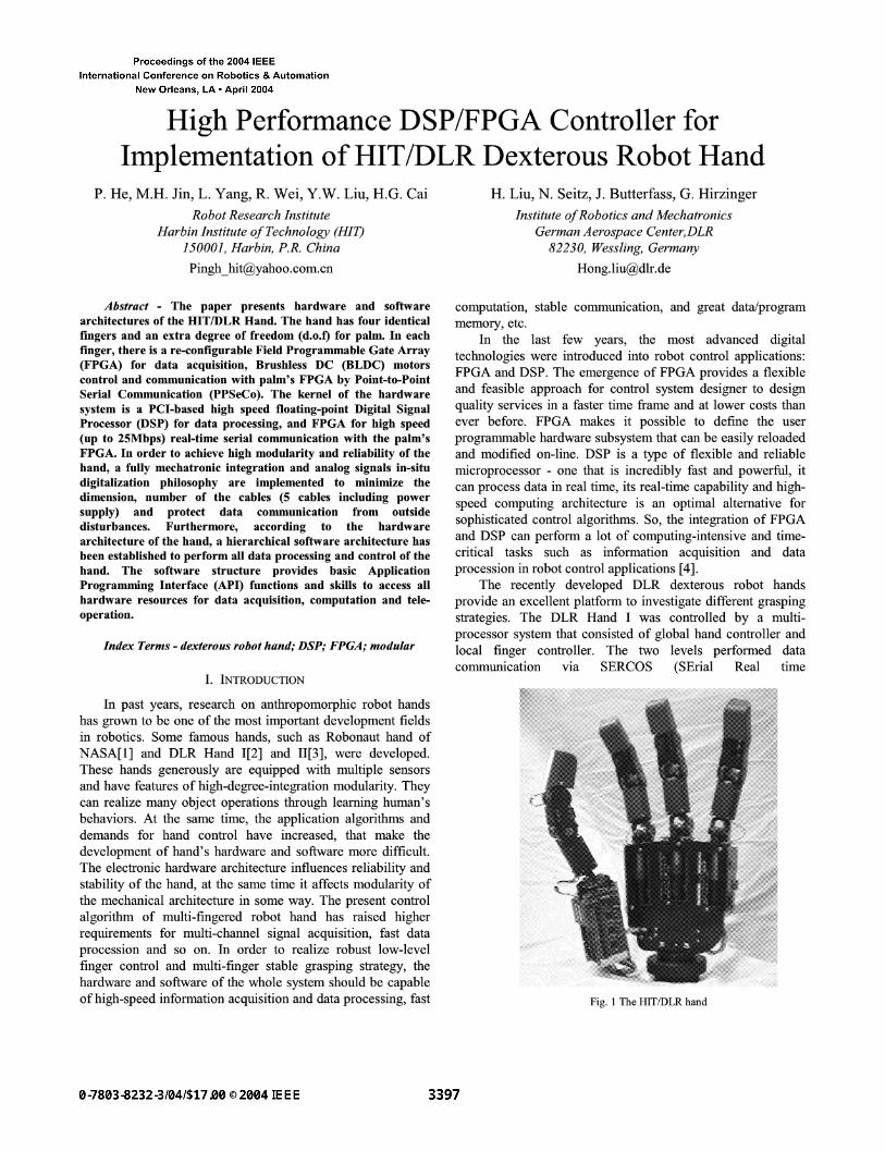
necessary electronics and actuators in the fingers and the palm of the hand. The fully integrated concept is helpful for the hand to achieve high-degree modularity and to reduce the whole size of the hand so that the HIT/DLR Hand's size would approximate to that of a human's hand. There are four finger modules (as shown in figure 2), each finger module integrates the finger FPGA, the B LDC motor board and the sensor boards together, and one finger module is an independent subsystem of the hand. The electronic hardware architecture of one finger module is shown in figure 4.
The finger FPGA board is responsible for information management and data processing inside the finger module. The fully digital sensor signals out from the sensor boards are just numeric values without any physical meaning, so they cannot be used directly in control algorithms. The finger FPGA converts them into physical dimensions of joint angles and velocities through sensor calibration and packs them into a data package which will be transmitted to the palm FPGA board via PPSeCo system. The connection between the finger FPGA board and the BLDC motor board is realized through general board-to-board interface.
The BLDC motor is chosen as driving component for the HIT/DLR Hand. In order to decrease area of the BLDC motor
Sensor I~il Control P alDmaFpt G ~ [ p alataF pfrG2
Power Supply J ~
seTa, ; Interface
/ ~ ~ ADC ~1~ ~IVI) UVI) 16 CH - - ~ ~n t ro l l e r
3 Power Converters
~ , H all Sensor
3 Motor Controller ~ - ~o~trol Signals
Fig. 4 Electronic architecture of one finger module
" . . . . . .~ ~'~" ~4.
. ~ ~ ~ ..~-.~5~' ,i
I v
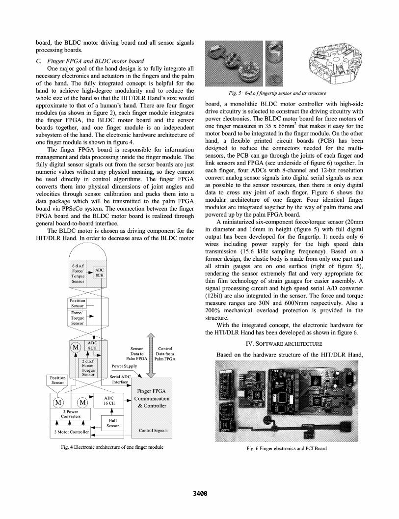
Fig. 5 6-d.o.f fingertip sensor and its structure
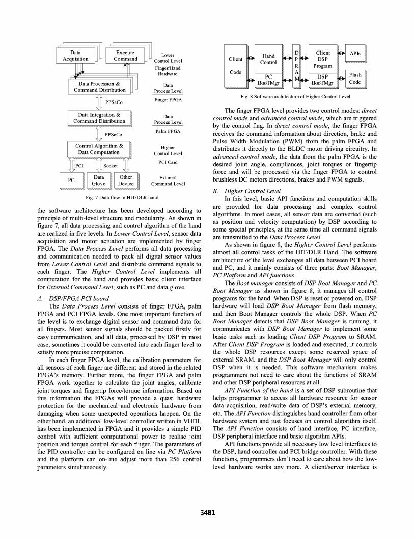
board, a monolithic BLDC motor controller with high-side drive circuitry is selected to construct the driving circuitry with power electronics. The BLDC motor board for three motors of one finger measures in 35 x 65mm 2 that makes it easy for the motor board to be integrated in the finger module. On the other hand, a flexible printed circuit boards (PCB) has been designed to reduce the connectors needed for the multi- sensors, the PCB can go through the joints of each finger and link sensors and FPGA (see underside of figure 6) together. In each finger, four ADCs with 8-channel and 12-bit resolution convert analog sensor signals into digital serial signals as near as possible to the sensor resources, then there is only digital data to cross any joint of each finger. Figure 6 shows the modular architecture of one finger. Four identical finger modules are integrated together by the way of palm frame and powered up by the palm FPGA board.
A miniaturized six-component force/torque sensor (20mm in diameter and 16mm in height (figure 5) with full digital output has been developed for the fingertip. It needs only 6 wires including power supply for the high speed data transmission (15.6 kHz sampling frequency). Based on a former design, the elastic body is made from only one part and all strain gauges are on one surface (right of figure 5), rendering the sensor extremely flat and very appropriate for thin film technology of strain gauges for easier assembly. A signal processing circuit and high speed serial A/D converter (12bit) are also integrated in the sensor. The force and torque measure ranges are 30N and 600Nmm respectively. Also a 200% mechanical overload protection is provided in the structure.
With the integrated concept, the electronic hardware for the HTI/DLR Hand has been developed as shown in figure 6.
IV. SOFTWARE ARCHITECTURE
Based on the hardware structure of the HIT/DLR Hand, iii~!~!i~iiiii~i~ii~iiii~iii~iiiiiiiiiiiiiiiiiiiiiiiiiiiiiiiiii~!i!!iii!!iiiiiiiiiiiiii!iiiiiii~iii!!!!ii!iii!i!~i~iiiiiiiii!!!!!i~i~i~i~iii!ii!ii~ii~ii~ii~iii~i~ii~iii~i~ii~iii~ii~ii~!iiiiiiiiiii~i!ii~i~i~ii~ii~!i~!i~! iiiiiiiiiiiiiiiiiiiiiiiiiiiiiiiiiiiiiiiiiiiiiiiiiiiiiiiiiiiiiiiiiiiiiiiiii!i~ iiiiiiii~ii~!~iiiiii!~!!iiii~i~i~i~i~i~i~i~iiii~i~iiiiii~iii~i~i~iiiiii!i!~!~ii~iiiiiii~iiiiiiiiii~i~i~i~iii~iiiiiiiiii~ii~iiiiiiiii!i~ii!i!ii~i!iiii~ii~iiiiii~iii~iiiiiiiiiiiiii~:~::~::~i~i~i ~:~i~i~i~iiiii~iiiiiiiiiiii::~:i!!i!iiiiiiiiiiiii!i~iiiiiiiiiiiiiii~iii~i~'~'iiii!~ii~i~iiiiiiiiiii~!i!ii~!iiiiii ~iiiii!iiiiiiiiiiiiiiiiiiiiiiii~::~::~::~i~iiiiiiiiiiiiii~iiiii~
i ii!iiiiiiiiii
Fig. 6 Finger electronics and PCI Board
r r I I
Data _ Execute Lower Acquisition Command Control Level
TT Finger/Hand ,, I Hardware
a::nrd D~bu&ti ~ Data Co on Process Level
I PPSeCo Finger FPGA
Data Integration & Data Command Distribution Process Level
......................................................................................... . - .:: ..............................................................................................
I I Palm FPGA PPSeCo
Control Algorithm & ~ Higher Data Computation ~ Control Level
: i ::P:C:I ...................................... ::i :::::~::::::k::: ................ : i PCI Card
1 ° °rl ............... ommanaa' PC L::::::G:ove : : : : : : : : : Level .................................................................... ..................................................................... ',i~',
Fig. 7 Data flow in HIT/DLR hand
the software architecture has been developed according to principle of multi-level structure and modularity. As shown in figure 7, all data processing and control algorithm of the hand are realized in five levels. In Lower Control Level, sensor data acquisition and motor actuation are implemented by finger FPGA. The Data Process Level performs all data processing and communication needed to pack all digital sensor values from Lower Control Level and distribute command signals to each finger. The Higher Control Level implements all computation for the hand and provides basic client interface for External Command Level, such as PC and data glove.
A. DSP/FPGA PCI board The Data Process Level consists of finger FPGA, palm
FPGA and PCI FPGA levels. One most important function of the level is to exchange digital sensor and command data for all fingers. Most sensor signals should be packed firstly for easy communication, and all data, processed by DSP in most case, sometimes it could be converted into each finger level to satisfy more precise computation.
In each finger FPGA level, the calibration parameters for all sensors of each finger are different and stored in the related FPGA's memory. Further more, the finger FPGA and palm FPGA work together to calculate the joint angles, calibrate joint torques and fingertip force/torque information. Based on this information the FPGAs will provide a quasi hardware protection for the mechanical and electronic hardware from damaging when some unexpected operations happen. On the other hand, an additional low-level controller written in VHDL has been implemented in FPGA and it provides a simple PID control with sufficient computational power to realist joint position and torque control for each finger. The parameters of the PID controller can be configured on line via PC Platform and the platform can on-line adjust more than 256 control parameters simultaneously.
. , ~ ~ Cl ien t ~O~ APIs ~ Client ~ llano ~ p ~ DSP liiil I liiil
[il ] Control [ RI l Program [il ~ ......................................................
L ............................................................... e ............. B
Fig. 8 Software architecture of Higher Control Level
The finger FPGA level provides two control modes: direct control mode and advanced control mode, which are triggered by the control flag. In direct control mode, the finger FPGA receives the command information about direction, brake and Pulse Width Modulation (PWM) from the palm FPGA and distributes it directly to the BLDC motor driving circuitry. In advanced control mode, the data from the palm FPGA is the desired joint angle, compliances, joint torques or fingertip force and will be processed via the finger FPGA to control brushless DC motors directions, brakes and PWM signals.
B. Higher Control Level In this level, basic API functions and computation skills
are provided for data processing and complex control algorithms. In most cases, all sensor data are converted (such as position and velocity computation) by DSP according to some special principles, at the same time all command signals are transmitted to the Data Process Level.
As shown in figure 8, the Higher Control Level performs almost all control tasks of the HIT/DLR Hand. The software architecture of the level exchanges all data between PCI board and PC, and it mainly consists of three parts: Boot Manager, PC Platform and API functions.
The Boot manager consists of DSP Boot Manager and PC Boot Manager as shown in figure 8, it manages all control programs for the hand. When DSP is reset or powered on, DSP hardware will load DSP Boot Manager from flash memory, and then Boot Manager controls the whole DSP. When PC Boot Manager detects that DSP Boot Manager is running, it communicates with DSP Boot Manager to implement some basic tasks such as loading Client DSP Program to SRAM. After Client DSP Program is loaded and executed, it controls the whole DSP resources except some reserved space of external SRAM, and the DSP Boot Manager will only control DSP when it is needed. This software mechanism makes programmers not need to care about the functions of SRAM and other DSP peripheral resources at all.
API Function of the hand is a set of DSP subroutine that helps programmer to access all hardware resource for sensor data acquisition, read/write data of DSP's external memory, etc. The API Function distinguishes hand controller from other hardware system and just focuses on control algorithm itself. The API Function consists of hand interface, PC interface, DSP peripheral interface and basic algorithm APIs.
API functions provide all necessary low level interfaces to the DSP, hand controller and PCI bridge controller. With these functions, programmers don't need to care about how the low- level hardware works any more. A client/server interface is

......... , 0r 0T . . . . . . . . "
i ~.<..!i~iiiIiiiiiiiiiiiiiIiiiiiiii!i!i~iiiiii!!ii~i~i~iii~iii~i~iii~iii~iiiiiiiiiiiiiiiiiiiiiiiiiiiiiiiiiiiiiiiiiiiiiiiiiii~i~.~i~
Fig. 9 PC platform for hand control
designed to construct communication with force feedback data glove and graphic workstation via 100MBit Ethernet. Programmers can also design special control strategy based on these API functions to test and control the hand or achieve tele-operation by the data glove.
In order to provide a friendly client interface, P C Plat form
is developed based on P C boot manager as shown in figure 9. The P C Plat form is a detail graphic and numerical interface to monitor and display almost all states of the hand during test and control tasks. It can also control and test each finger directly. All original sensor signals should be calibrated before applied to control algorithm, the P C Plat form can performs the calibration in minutes with the parameters of all sensors stored in finger FPGA. It's important to supervise the behaviors of client program in real time, but in most cases, there is no DSP hardware debugger for programmers to debug their control programs. The P C Plat form provides interfaces to track some interesting local variables of the program and watch the running state of programs. For example, programmers can obtain some interesting variables and watch them intuitively by drawing them.
C. External C o m m a n d Leve l
In most control tasks, user's attendance is usually needed to control the HIT/DLR Hand in real time according to special situation or achieve tele-operation via the data glove. The External Level provides interfaces to connect with the Higher
Control Leve l and distribute such control instructions. Further more, a graphic work station can be connected through Ethernet to display state of the hand in visual environment.
V. CONCLUSIONS AND FUTURE W O R K
The paper presents a low-cost high performance hardware and software architecture for new generation dexterous robot hand. With this basic architecture, many control applications for the hand have been successfully demonstrated such as music playing, autonomously grasping of a bottle and tele- operation experiments. The future work will be concentrated on the whole system reliability and small series manufacturing.
REFERENCES
[ 1 ] C.S. Lovchik and M. A. Diftler, "The Robonaut Hand: a dexterous robot hand for space," In Proc. IEEE Conf. on Robotics and Automation, pp. 907-912, Detroit, Michigan, USA, May 1999
[2] H. Liu, J. Butterfass, S.Knoch, P.Meusel, G. Hirzinger. A New Control Strategy for DLR's Multisensory Articulated Hand. IEEE Control Systems. 1999,19(2) pp. 47-54
[3] J. Butterfass, M. Grebenstein, H. Liu, G. Hirzinger, "DLR-Hand II: Next generation of a dexterous robot hand," In Proceedings of the 2001 IEEE International conference on Robotics & Automation. 2001, pp. 109-114
[4] Zbigniew Bielewicz, Leszek Debowski, etc, "A DSP and FPGA based integrated controller development solution for high performance electronic drives," Industrial Electronics, vol.2,1996, pp. 679-684
[5] S.Haidacher, J. Butterfass, M. Fischer, M. Grebenstein, K. Joehl, K. Kunze, M. Nickl, N. Seitz and G. Hirzinger, "DLR Hand II: hard- and software architecture for information processing," Proceedings of the 2003 IEEE International Conference on Robotics & Automation, Taipei, Taiwan, 2003, pp. 684-689
[6] X.H. Gao, M.H. Jin, L. Jiang, Z.W. Xie, P. He, "The HIT/DLR dexterous hand: work in progress," Proceedings of the 2003 IEEE International Conference on Robotics & Automation, Taipei, Taiwan, 2003 , pp. 3164- 3168
[7] TMS320C6711, TMS320C6711B, TMS320C6711C, "Floating-point digital signal processors," The technology document of TI company. SPRS088E-February 1999