A Controller Implementation using FPGA in LabVIEW … · A Controller Implementation using FPGA in...
11
Paper ID #7197 A Controller Implementation using FPGA in LabVIEW Environment Dr. Biswanath Samanta, Georgia Southern University Dr. Biswanath Samanta is in the Department of Mechanical Engineering at Georgia Southern University in Statesboro, Ga. His expertise and research interests include broad areas of system dynamics and control, robotics, mechatronics, intelligent systems, advanced signal processing, prognostics and health manage- ment, and applications of computational intelligence in engineering and biomedicine. Dr. Samanta has developed and taught numerous courses in these areas and supervised students at both undergraduate and graduate levels. He has more than 100 refereed research articles published by professional bodies like ASME, IMechE, AIAA, and IEEE. The papers are regularly cited by independent researchers in their publications (more than 1,500 citations). He is a member of ASEE, ASME and a senior member of IEEE. Jonathan Gregory Turner, Georgia Southern University Jonathan Turner is a control systems engineer at Genetec Technology Automation in Greenville, South Carolina. He earned his master of science in Applied Engineering from Georgia Southern University in 2012. His research interests include intelligent and artificial neural network based control systems engi- neering; specifically the application of intelligent control systems in autonomous and mobile applications. His educational interests include supporting the integration of a unified arts and embedded electronics cur- riculum in early childhood education. c American Society for Engineering Education, 2013 Page 23.36.1
Transcript of A Controller Implementation using FPGA in LabVIEW … · A Controller Implementation using FPGA in...
Paper ID #7197
A Controller Implementation using FPGA in LabVIEW Environment
Dr. Biswanath Samanta, Georgia Southern University
Dr. Biswanath Samanta is in the Department of Mechanical Engineering at Georgia Southern University inStatesboro, Ga. His expertise and research interests include broad areas of system dynamics and control,robotics, mechatronics, intelligent systems, advanced signal processing, prognostics and health manage-ment, and applications of computational intelligence in engineering and biomedicine. Dr. Samanta hasdeveloped and taught numerous courses in these areas and supervised students at both undergraduate andgraduate levels. He has more than 100 refereed research articles published by professional bodies likeASME, IMechE, AIAA, and IEEE. The papers are regularly cited by independent researchers in theirpublications (more than 1,500 citations). He is a member of ASEE, ASME and a senior member of IEEE.
Jonathan Gregory Turner, Georgia Southern University
Jonathan Turner is a control systems engineer at Genetec Technology Automation in Greenville, SouthCarolina. He earned his master of science in Applied Engineering from Georgia Southern University in2012. His research interests include intelligent and artificial neural network based control systems engi-neering; specifically the application of intelligent control systems in autonomous and mobile applications.His educational interests include supporting the integration of a unified arts and embedded electronics cur-riculum in early childhood education.
c©American Society for Engineering Education, 2013
Page 23.36.1
A Controller Implementation using FPGA in LabVIEW
Environment
Abstract: The paper presents a case study of introducing field programmable gate array (FPGA) based implementation of controllers in LabVIEW environment in a graduate Mechatronics course. The process of system identification, controller design and its implementation is illustrated using a physical system in the laboratory setting. The students’ survey response on the introduction of FPGA based controller implementation in the course is mostly positive.
I. Introduction There is a wide-spread interest in field programmable gate array (FPGA) based implementation of controllers in industrial applications1-5. FPGAs consist of reprogrammable gate array logic circuits and offer flexibility, reliability, and high-speed parallel execution1,2,6,7. Traditionally FPGA courses are offered in programs in Electrical and Computer Engineering (ECE)8-10. To better prepare the engineering students in FPGA technology, especially those in control systems area, there is a need to introduce FPGA based devices and their applications in engineering programs beyond ECE. Among different options available for introduction of FPGA based systems in engineering courses, the reconfigurable data acquisition devices (RIO) and LabVIEW FPGA module 11,12 from National Instruments (NI) provide access to FPGA based platforms with a high level programming language support in a laboratory setting. To satisfy the need of keeping the program content current, FPGA based data acquisition and control systems along with LabVIEW from NI were introduced in a graduate Mechatronics course in the Department of Mechanical Engineering at Georgia Southern University. The paper presents the implementation of a digital controller using FPGA in LabVIEW environment within a graduate Mechatronics course. The rest of the paper is organized as follows. Section II describes briefly the example system used for illustrating the process of system identification, controller design and implementation. Section III discusses the procedure of experimentally identifying the system model parameters. Section IV describes the design of a digital PID controller using MATLAB13. In Section V, the implementation of the discrete-time controller is described using FPGA based hardware and LabVIEW software. Controller implementation results are presented in Section VI. Students’ survey responses are discussed in Section VII. The salient points of the work and the future scope are summarized in Conclusion. II. Example System A position control system was implemented for a physical system to reinforce concepts learned in Mechatronics coursework. The controlled physical system was a rectilinear spring-mass-damper system, Model M210, from Educational Control Products (ECP)14. MATLAB from Mathworks13 aided the design of a discrete-time PID controller. National instruments LabVIEW was used to implement the control system and an FPGA based data acquisition hardware was
Page 23.36.2
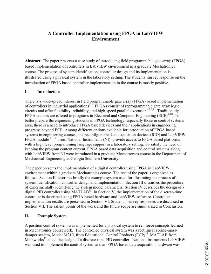
used to interface software controls and the physical system10,11. The physical system used for control implementation is shown in Fig. 1. The model depicts a 3 degree-of freedom system in rectilinear motion consisting of 3 blocks (carts) of mass connected through 3 springs and a damper. Each cart is equipped with an optical encoder for measuring its position. The cart system is driven by a DC motor. An inverted pendulum unit can be attached to any of the blocks for an additional degree of freedom and also adding as a disturbance. An optical encoder is attached to the pendulum base to measure its angular position. In the present experiment, a single degree-of-freedom system is considered using only the first mass-spring combination.
Figure 1: ECP M210 system used for position control A National Instruments PCI-7831R reconfigurable input/output (I/O) card11 was used to interface optical encoders for system position feedback and to provide a control signal. The NI PCI-7831R is a multifunction, reconfigurable I/O device. The centerpiece of the data acquisition card is a Xilinx Virtex-II FPGA. The 1 million gate FPGA is used to control the 96 configurable digital I/O lines and allows programming of custom logic to customize the functionality of the hardware. The PCI-7831R also provides 8 analog inputs and 8 analog outputs. The analog inputs have independently configurable sampling rates up to 200 kHz, and 16-bit resolution over a maximum input voltage range of ±10V. The analog outputs also have 16-bit resolution and can be updated up to 1 million times a second. A power amplifier from ECP was used to condition the control signal and drive the DC motor for the cart. The objective of this lab activity was to identify the system model parameters, design a PID controller in discrete-time domain for controlling the position of the cart and implement the controller using the FGPA based hardware in LabVIEW environment. III. System Identification
The physical system was modeled as a second order system given by the transfer function in Eq. (1) where k is the steady state gain, ωn represents the natural frequency of the system, and ζ is the P
age 23.36.3

damping ratio. The system model included the dynamic effects of the power amplifier, the system dynamic components and the position sensing equipment.
(1)
A bump test was carried out to determine the model parameters (k, ωn, and ζ). The system was excited using a step input of 1V to the DC motor and the cart position was recorded. The entire procedure was carried out using the PCI-7381R FPGA based card in LabVIEW environment. The obtained system response from the collected data is shown in Fig. 2.
Figure 2: Cart position vs. time data from bump test Equation 2 was used to calculate the value of k from the collected data, where xss represents the steady state position of the cart and Vin is the voltage applied to the motor.
ss
in
xk
V (2)
The damping coefficient was calculated next using the relationship shown in Eq. (3) and the data from the bump test.
2
2
1 1
2
xe
x
(3)
The natural frequency of the system was calculated using bump test data and ωd where:
0
5
10
15
20
25
30
0 0.2 0.4 0.6 0.8 1 1.2 1.4 1.6
Cart Position (mm)
Time (s)
Cart Position vs. Time
Cart Position
SteadyState
x1x2
Page 23.36.4

2d
dT
(4)
The component Td is the time period of damped oscillation. The natural frequency of the system was calculated using Eq. (5).
21d n (5)
The parameters obtained from the bump test data are as follows: k=15.86 mm/V, ζ=0.036, and ωn=12.57 rad/s. IV. Controller Design A discrete-time PID controller was designed for the position control of the cart using its identified model parameters. A sampling time of 0.025 s was used for the system. A desired pole location in s-domain was used to obtain a closed loop system with a damping ratio of 0.8 and a frequency of 15 rad/s. The desired pole location was selected to achieve a fast response with low overshoot for the closed loop position control system. The PID controller was designed based on pole placement technique15 using MATLAB as covered in the Mechatronics course16. The transfer function of the designed PID controller in z-domain is shown in Eq. (6)
0.3716 0.6581 0.3053
6
V. Controller Implementation
The LabVIEW implementation of the control system consisted of two main parts; (i) host PC virtual instrument (VI) and (ii) FPGA VI. A host PC VI was developed to model the PID control transfer function and interact with the FPGA based RIO hardware. The FPGA VI was programmed in LabVIEW and synthesized to run on the FPGA. The FPGA VI was used to interpret the signal from high resolution optical encoders attached to the moving carts and communicate a feedback signal to the host PC VI over the local PCI bus for generating the control signal to the motor. Host VI The logic used to implement the PID control is presented as the host PC VI block diagram in Fig. 3. The host VI is controlled by a timer that makes sure the I/O operations and calculations in the enclosed blocks are completed within the specified time. The timer value is set equal to the sampling time. The cart position, measured in encoder pulses from the zero starting point, is gathered from the FPGA and is scaled into a measured position in millimeters. An error signal is calculated as the difference between the actual and the desired cart position and is input to the controller transfer function. The controller transfer function uses the error signal to calculate the required control voltage signal. The control signal is scaled from a voltage unit to a decimal representation of the necessary 16-bit binary output of the RIO board. The control signal is input to a saturation function that guarantees the signal level is always in a valid range before being sent to the FPGA for output register update. The host PC VI also has connections to the VI front panel for user control. The loop timer and encoder values can be manipulated and input/output
Page 23.36.5

values are displayed. These user connections to the VI are also available for control software debugging and data logging. The host computer software opens an RIO interface, reads and writes data to the FPGA while performing control calculations and then closes the RIO session when complete. The host VI also provides saturation to protect the system from voltage spikes. The front panel of the host VI is shown in Fig. 4 to outline the available user inputs. The host VI front panel allowed selection of the RIO resource, adjustment of the data acquisition sampling time, entry of the desired cart position, reset of the cart position and toggling of the encoder direction sign convention. Visual feedback was also provided in the form of cart position and control output readouts.
Figure 3: Host PC VI block diagram to perform control calculations and interface the FPGA card
Figure 4: Host VI Front panel
Page 23.36.6
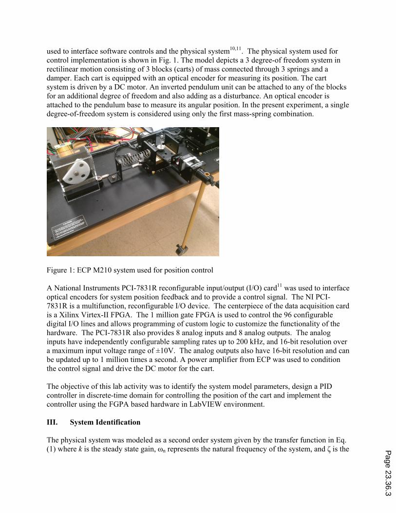
FPGA VI The other component to be implemented in software was the FPGA based data acquisition. Quadrature encoders were used to get cart position data. The logic used to collect encoder data from the VI running on the RIO card is presented in the block diagram of Fig. 5 and the entire block diagram of the VI implemented on the FPGA is provided in Fig. 6.
Figure 5: FPGA VI block diagram part for reading quadrature encoder data
The block diagram in Fig. 5 reads current encoder register outputs, compares it to a previous value for each register to update encoder shaft direction and increment or decrement the position value. The FPGA VI exists inside a while loop that runs continuously while the host PC VI is running. The encoder A and B signal lines are read when the FPGA VI starts and the initial values are stored in a register. The cart current position register initializes to a value of 0 mm. The second iteration of the software moves the last read encoder signal values into a comparison register to determine if the current encoder signal is the same as the previous one. A cart position variable is incremented if a signal line has changed. The increment of the cart position is positive if the A signal has changed and negative if the B signal has changed. The FPGA VI sends the value in the cart position register to the Host PC VI, over the local PCI bus, for scaling and use in the control loop. The FPGA VI also controls the analog output voltage by updating the value in the output register. The Host PC VI sends the control output to the FPGA which writes the desired analog output to the appropriate register at every sampling time. A pair of digital inputs and an analog output of the PCI-7831R were used to interface the physical system. The analog output provided bi-directional control of the cart position. Two digital inputs were used to read signal lines from a quadrature encoder mounted to an axle on the cart. P
age 23.36.7

After hardware and software were setup, the controller was tested to determine if the expected and acceptable cart position control was achieved.
Figure 6. FPGA VI block diagram for controller implementation
Page 23.36.8
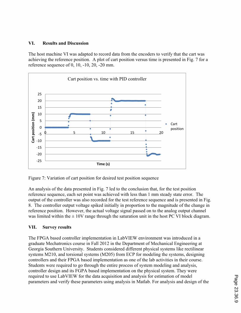
VI. Results and Discussion The host machine VI was adapted to record data from the encoders to verify that the cart was achieving the reference position. A plot of cart position versus time is presented in Fig. 7 for a reference sequence of 0, 10, -10, 20, -20 mm.
Figure 7: Variation of cart position for desired test position sequence
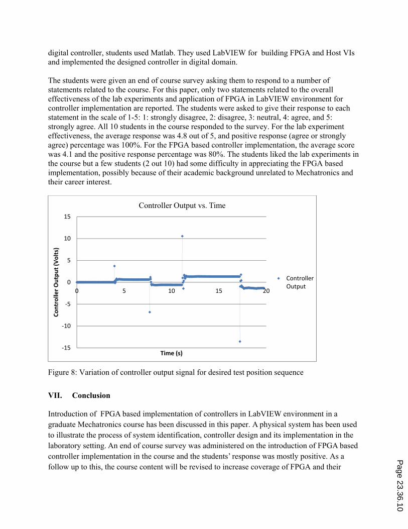
An analysis of the data presented in Fig. 7 led to the conclusion that, for the test position reference sequence, each set point was achieved with less than 1 mm steady state error. The output of the controller was also recorded for the test reference sequence and is presented in Fig. 8. The controller output voltage spiked initially in proportion to the magnitude of the change in reference position. However, the actual voltage signal passed on to the analog output channel was limited within the ± 10V range through the saturation unit in the host PC VI block diagram. VII. Survey results The FPGA based controller implementation in LabVIEW environment was introduced in a graduate Mechatronics course in Fall 2012 in the Department of Mechanical Engineering at Georgia Southern University. Students considered different physical systems like rectilinear systems M210, and torsional systems (M205) from ECP for modeling the systems, designing controllers and their FPGA based implementation as one of the lab activities in their course. Students were required to go through the entire process of system modeling and analysis, controller design and its FGPA based implementation on the physical system. They were required to use LabVIEW for the data acquisition and analysis for estimation of model parameters and verify these parameters using analysis in Matlab. For analysis and design of the
‐25
‐20
‐15
‐10
‐5
0
5
10
15
20
25
0 5 10 15 20
Cart position (mm)
Time (s)
Cart position vs. time with PID controller
Cartposition
Page 23.36.9
digital controller, students used Matlab. They used LabVIEW for building FPGA and Host VIs and implemented the designed controller in digital domain. The students were given an end of course survey asking them to respond to a number of statements related to the course. For this paper, only two statements related to the overall effectiveness of the lab experiments and application of FPGA in LabVIEW environment for controller implementation are reported. The students were asked to give their response to each statement in the scale of 1-5: 1: strongly disagree, 2: disagree, 3: neutral, 4: agree, and 5: strongly agree. All 10 students in the course responded to the survey. For the lab experiment effectiveness, the average response was 4.8 out of 5, and positive response (agree or strongly agree) percentage was 100%. For the FPGA based controller implementation, the average score was 4.1 and the positive response percentage was 80%. The students liked the lab experiments in the course but a few students (2 out 10) had some difficulty in appreciating the FPGA based implementation, possibly because of their academic background unrelated to Mechatronics and their career interest.
Figure 8: Variation of controller output signal for desired test position sequence
VII. Conclusion Introduction of FPGA based implementation of controllers in LabVIEW environment in a graduate Mechatronics course has been discussed in this paper. A physical system has been used to illustrate the process of system identification, controller design and its implementation in the laboratory setting. An end of course survey was administered on the introduction of FPGA based controller implementation in the course and the students’ response was mostly positive. As a follow up to this, the course content will be revised to increase coverage of FPGA and their
‐15
‐10
‐5
0
5
10
15
0 5 10 15 20
Controller Output (Volts)
Time (s)
Controller Output vs. Time
ControllerOutput
Page 23.36.10

applications in next offering of the course. More experiments with FPGA based implementation of more advanced control algorithms will also be introduced.
In this paper, only PID controller implementation has been presented as an example. The implementation of other forms of controllers including artificial neural networks using FPGA in LabVIEW is in progress. The introduction of FPGA based devices and their applications in control system implementation in a mechanical engineering senior elective course is under active consideration.
Bibliography
1. Monmasson, E., and Cirstea, M. N. (2007). FPGA design methodology for industrial control systems—a review, IEEE Transactions on Industrial Electronics, vol. 54, no. 4, pp. 1824-1842.
2. Monmasson, E., Idkhajine, L., Cirstea, M. N., Bahri, I., Tisan, A., and Naouar, M. W. (2011). FPGAs in industrial control applications, IEEE Transactions on Industrial Informatics, vol. 7, no. 2, pp. 224-243.
3. Jung, S., and Kim, S. S. (2007). Hardware implementation of a real-time neural network controller with a DSP and an FPGA for nonlinear systems, IEEE Transactions on Industrial Electronics, vol. 54, no. 1, pp. 265-271.
4. Pearson, M. J., Pipe, A. G., Mitchinson, B., Gurney, K., Melhuish, C., Gilhespy, I., and Nibouche, M. (2007). Implementing spiking neural networks for real-time signal-processing and control applications: a model-validated FPGA approach, IEEE Transactions on Neural Networks, vol. 18, no. 5, pp. 1472-1487.
5. Orlowska-Kowalska, T., and Kaminski, M. (2011), FPGA implementation of the multilayer neural network for the speed estimation of the two-mass drive system, IEEE Transactions on Industrial Informatics, vol. 7, no. 3, pp. 436-445.
6. National Instruments (2012). FPGA fundamentals, www.ni.com/white-paper/6983/en. 7. National Instruments (2012). FPGA-based control: millions of transistors at your command (FAQ),
http://www.ni.com/white-paper/3357/en. 8. Radu, M., Cole, C., Dabacan, M. A., and Sexton, S. (2008). Extensive use of advanced FPGA technology in
digital design education, ASEE Annual Conference Proceedings. 9. Perales, T., Morgan, J., and Porter, J. (2009). A LabVIEW FPGA toolkit to teach digital logic design, ASEE
Annual Conference Proceedings. 10. Korpela, C., and McTasney, R. (2009). An FPGA multiprocessor system for undergraduate study, ASEE Annual
Conference Proceedings. 11. National Instruments (2012). NI LabVIEW FPGA module, www.ni.com/labview/fpga. 12. National Instruments. Getting started with the NI 7831R, http://www.ni.com/pdf/manuals/323256b.pdf. 13. http://www.mathworks.com 14. http://www.ecp.com 15. Phillips, C. L. and Parr, J. M. (2011). Feedback Control Systems, Fifth Edition, Prentice Hall. 16. Samanta, B. (2013). Lecture Notes of Mechatronics I and II, Georgia Southern University.
Page 23.36.11