HGV inspection manual October 2015 update
212
Heavy Goods Vehicle Inspection Manual Safety Standards Service consolidated edition 2013
-
Upload
truongnhan -
Category
Documents
-
view
222 -
download
3
Transcript of HGV inspection manual October 2015 update

Heavy Goods Vehicle Inspection Manual
Safety Standards Service
consolidated edition 2013
01/01/2013 1 of 6 Document Uncontrolled When Printed
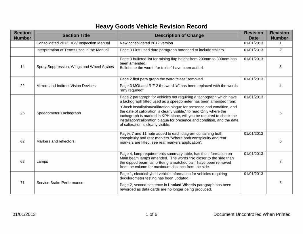
Heavy Goods Vehicle Revision Record Section Number Section Title Description of Change Revision
Date Revision Number
Consolidated 2013 HGV Inspection Manual New consolidated 2012 version 01/01/2013 1.
Interpretation of Terms used in the Manual
Page 3 First used date paragraph amended to include trailers. 01/01/2013 2.
14 Spray Suppression, Wings and Wheel Arches
Page 3 bulleted list for raising flap height from 200mm to 300mm has been amended. Bullet one the words “or trailer” have been added.
01/01/2013
3.
22 Mirrors and Indirect Vision Devices
Page 2 first para graph the word “class” removed.
Page 3 MOI and RfF 2 the word “a” has been replaced with the words “any required”
01/01/2013
4.
26 Speedometer/Tachograph
Page 2 paragraph for vehicles not requiring a tachograph which have a tachograph fitted used as a speedometer has been amended from: “Check installation/calibration plaque for presence and condition, and the date of calibration is clearly visible.” to read Only where the tachograph is marked in KPH alone, will you be required to check the installation/calibration plaque for presence and condition, and the date of calibration is clearly visible.
01/01/2013
5.
62 Markers and reflectors
Pages 7 and 11 note added to each diagram containing both conspicuity and rear markers “Where both conspicuity and rear markers are fitted, see rear markers application”.
01/01/2013
6.
63 Lamps
Page 4, lamp requirements summary table, has the information on Main beam lamps amended. The words “No closer to the side than the dipped beam lamp Being a matched pair” have been removed from the column for maximum distance from the side.
01/01/2013
7.
71 Service Brake Performance
Page 1, electric/hybrid vehicle information for vehicles requiring decelerometer testing has been updated.
Page 2, second sentence in Locked Wheels paragraph has been reworded as data cards are no longer being produced.
01/01/2013
8.

01/07/2013 2 of 6 Document Uncontrolled When Printed
Section Number Section Title Description of Change Revision
Date Revision Number
Standards for Prohibition IM38 - Vacuum assistance is not working – this now has a single asterisk.
20/03/2013 9.
01 Registration Plate RfF 1 and 2 font now in black. 20/03/2013 10.
03 03 Seat Belts & Supplementary Restraint Systems
RfF 7, 8 and 9 font now in black. 20/03/2013 11.
18 Seats RfF 2 and 3 font now in black. 20/03/2013 12.
22 Mirrors and Indirect Vision Devices
RfF 1 to 4 references to indirect vision devices and cameras font now in black.
Note added to page two “RfF 2 will not apply to cameras replacing front and or close proximity mirrors fitted less than 2 metres from the ground where the camera is hidden with in the body contour.”
20/03/2013
13.
26 Speedometer/Tachograph RfF 3d font now in black. 20/03/2013 14.
36 Hand Lever Operating Mechanical Brakes RfF 1i and j font now in black. 20/03/2013 15.
37 Service Brake Pedal RfF 2c and d font now in black. 20/03/2013 16.
38 Service Brake Operation RfF 5 (ESC reference), 6 and 7 font now in black.
RfF 3 now has only a single asterisk.
20/03/2013 17.
42 Electrical Wiring and Equipment RfF 4 font now in black. 20/03/2013 18.
48 Suspension RfF 1jand k font now in black. 20/03/2013 19.
54 Steering RfF 1 d, i, j and k font now in black.
RfF 2k, t, u and v font now in black.
20/03/2013 20.
58 Additional Braking Devices RfF 1 font now in black. 20/03/2013 21.
59 Brake Systems and Components
RfF 1 e font now in black.
RfF 5g, h and l font now in black.
RfF 6 font now in black.
20/03/2013
22.
63 Lamps RfF 4e and 5 font now in black. 20/03/2013 23.
Front cover New corporate logo added 01/07/2013 24.
About this manual Page 5, Training information updated 01/07/2013 25.

01/07/2013 3 of 6 Document Uncontrolled When Printed
Section Number Section Title Description of Change Revision
Date Revision Number
01 Registration Plate Application amended to clarify section only applies to registered vehicles.
01/07/2013 26.
14 Spray Suppression, Wings and Wheel Arches
Note “It is important to note however that this does not apply to spray suppression and therefore vehicles subject to the spray suppression requirements must have complete wings.” has been amended and includes spray suppression in the exemption.
01/07/2013
27.
38 Service Brake Operation
Page 3 paragrapgh “”If a trailer does not have a warning light”… “Failure 5” amended to “failure to 5a.”
Page 3 and 4 Information for ABS, ABS/EBS & EBS/ESC requirements reworded for clarity and ABS warning lamp procedure removed from page 4
Page 6 MOI and RfF 5, 6 & 7 wording amended for clarity now MOI & RfF 5, 6, 7 and 8.
01/07/2013
28.
53 Axles, Stub Axles and Wheel Bearings Page 1 application - Mercedes Sprinter information updated. Mercedes sprinters play and radial movement acceptable up to 3mm.
01/07/2013 29.
58 Additional Braking devices
Further information added to the application section:
• If the device has been removed and it is mandatory this will be a reason for failure, if the device is not mandatory the operator should be informed to complete a VTG10 notifiable alteration form. Where an exhaust brake operating cylinder and lever are completely removed, the housing containing the butterfly may be retained with the butterfly fixed in the open position.
• The check of operation is made by visual assessment, failure is justified only when it is obvious that a device is inoperative i.e. a disconnected linkage.
• Any inoperative device will be a reason for failure irrespective of whether it is mandatory or not.
01/07/2013
30.
62 Markers and Reflectors
Pages 5 to 12 updated to incorporate changes to the standards to apply for conspicuity markings including a note on page 8 which gives guidance on cab markings (50mm high by 50mm wide) and any gaps between the cab and body markings.
01/07/2013
31.
66 Direction Indicators and Hazard Warning Lamps
Page 2 – MOI and RfF 1b amended the words “and that it is visible to the rear” removed from MOI and “or not visible to the rear.” removed from RfF.
01/07/2013 32.
01/10/2014 4 of 6 Document Uncontrolled When Printed
Section Number Section Title Description of Change Revision
Date Revision Number
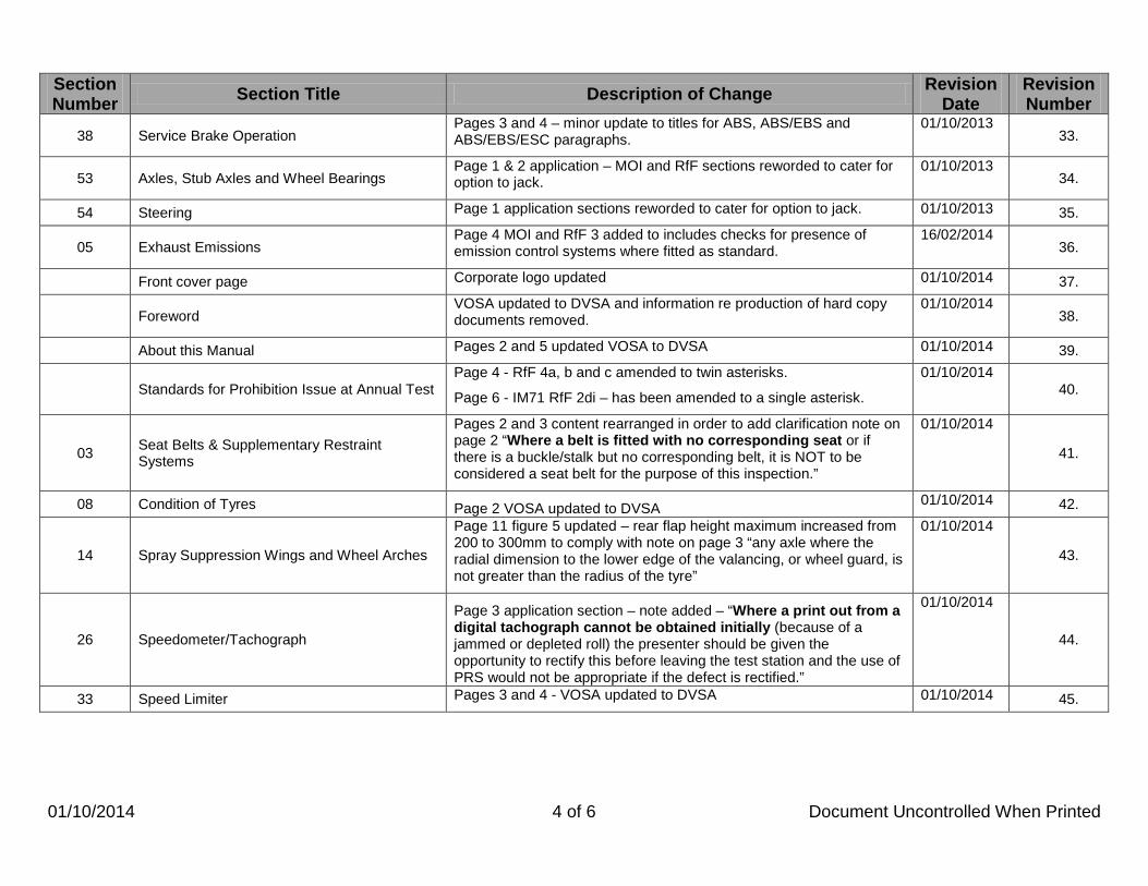
38 Service Brake Operation Pages 3 and 4 – minor update to titles for ABS, ABS/EBS and ABS/EBS/ESC paragraphs.
01/10/2013 33.
53 Axles, Stub Axles and Wheel Bearings Page 1 & 2 application – MOI and RfF sections reworded to cater for option to jack.
01/10/2013 34.
54 Steering Page 1 application sections reworded to cater for option to jack. 01/10/2013 35.
05 Exhaust Emissions Page 4 MOI and RfF 3 added to includes checks for presence of emission control systems where fitted as standard.
16/02/2014 36.
Front cover page Corporate logo updated 01/10/2014 37.
Foreword VOSA updated to DVSA and information re production of hard copy documents removed.
01/10/2014 38.
About this Manual Pages 2 and 5 updated VOSA to DVSA 01/10/2014 39.
Standards for Prohibition Issue at Annual Test Page 4 - RfF 4a, b and c amended to twin asterisks.
Page 6 - IM71 RfF 2di – has been amended to a single asterisk.
01/10/2014 40.
03 Seat Belts & Supplementary Restraint Systems
Pages 2 and 3 content rearranged in order to add clarification note on page 2 “Where a belt is fitted with no corresponding seat or if there is a buckle/stalk but no corresponding belt, it is NOT to be considered a seat belt
01/10/2014
for the purpose of this inspection.” 41.
08 Condition of Tyres Page 2 VOSA updated to DVSA 01/10/2014 42.
14 Spray Suppression Wings and Wheel Arches
Page 11 figure 5 updated – rear flap height maximum increased from 200 to 300mm to comply with note on page 3 “any axle where the radial dimension to the lower edge of the valancing, or wheel guard, is not greater than the radius of the tyre”
01/10/2014
43.
26 Speedometer/Tachograph
Page 3 application section – note added – “Where a print out from a digital tachograph cannot be obtained initially (because of a jammed or depleted roll) the presenter should be given the opportunity to rectify this before leaving the test station and the use of PRS would not be appropriate if the defect is rectified.”
01/10/2014
44.
33 Speed Limiter Pages 3 and 4 - VOSA updated to DVSA 01/10/2014 45.

01/04/2015 5 of 6 Document Uncontrolled When Printed
Section Number Section Title Description of Change Revision
Date Revision Number
38 Service Brake Operation
Page 3 – ABS only vehicles first paragraph, clarification for MIL illumination added “(ignition on)” changed to “(ignition or battery master switch on)”.
Page 3 – ABS only vehicles second paragraph, note added (On some trailers the trailer warning lamp may be extinguished when the ISO7638 cable is fitted).
01/10/2014
46.
45 Fuel Tanks and System Page 2 RfF 4a,b and c now have twin asterisks. 01/10/2014 47.
58 Additional Braking devices Application section note for visual assessment and the check of operation reworded.
01/10/2014 48.
63 Lamps
Page 1 - note added to application “The rear position lamps are permitted to be reciprocally incorporated with the rear fog lamp providing the positional requirements are met (when the fog lamp is switched on the rear position lamps intensity increases to become the fog lamp).” Page 5 - Rear fog lamp maximum height raised from 1000mm to 1200mm
01/10/2014
49.
71 Service Brake Performance Page 7 - RfF 2.d.i has been amended to a single asterisks 01/10/2014 50.
About this Manual Page 4 updated Vehicle and Operator Services Agency to Driver and Vehicle Standards Agency
01/04/2015 51.
Interpretation of Terms used in the Manual Page 7 Type approved note - second paragraph amended to address circumstances where a component or system is claimed to be type approved.
01/04/2015 52.
07 Size and Type of Tyres Page 1 & 12 updated Vehicle and Operator Services Agency to Driver and Vehicle Standards Agency
Page 5 Minor correction to single LI 108 and single LI 132
01/04/2015
53.

01/10/2015 6 of 6 Document Uncontrolled When Printed
Section Number Section Title Description of Change Revision
Date Revision Number
62 Markers and Reflectors
Page 6 & 7, 80% width requirement amended to 70%
Page 8, 80% length requirement amended to 70%. Second bullet amended removing “(not including the cab)” and adding measured from 2.4m from the extreme front of the vehicle. Page 8 note added “ As an alternative cab marking from using a 50mm X 50mm conspicuity marking within 600mm of the cab front, the cab may be marked using side reflectors with a minimum spacing of 600mm to within 600mm from the front of the cab.” Page 9, 80% length requirement amended to 70% and note “* Vehicle length excludes the cab but the cab must be marked.” Removed. Bullet point added “For trailers total cumulative length will be the full trailer length”.
01/04/2015
54.
66 Direction Indicators and Hazard Warning Lamps
Page 1 application section, note added “If more than one bulb or LED is fitted in the lamp at least 50% must work.
01/04/2015 55.
67 Aim of Headlamps Page 2 RfF 1, 2 and 3 have been revised and the aiming screen image replaced.
01/04/2015 56.
71 Service Brake Performance
Page 4 Note for testing tri axle trailers equipped with Knorr Bremse EBS/ABS amended – word “Unladen” removed and procedure F reworded.
Page 4, further information added to note for vehicles with hydrostatic drives - “Prior to roller brake testing any vehicle with hydrostatic drive and a transmission parking brake it may be necessary when the wheels are in the roller set to select neutral, switch off the ignition and restart the vehicle. Engaging this mode will prevent any hydrostatic retardation showing as excessive levels of bind.”
01/04/2015
57.
63 Lamps Application section page 3, “If more than two lamps are fitted...” replaced with “ If two or more lamps are fitted..”
01/10/2015 58.
66 Direction Indicators and Hazard Warning Lamps
Application section page 1, “If more than two lamps are fitted...” replaced with “ If two or more lamps are fitted..”
01/10/2015 59.
71 Service Brake Performance Page 7 MOI & RfF 2 the word “Other” has been replaced by “All”. 01/10/2015 60.
72 Secondary Brake Performance
Page 1 application amended to apply only to vehicles where the designated secondary is independent of the service brake. Page 1 paragraph for split systems removed and paragraph for alternative secondary options also removed. Page 2 MOI & RfF 2 the word “Other” has been replaced by “All”.
01/10/2015
61.

Heavy Goods Vehicle Inspection Manual
01/10/2014 1 of 1 Document Uncontrolled When Printed
Foreword Welcome to this new edition of the Heavy Goods Vehicle Inspection Manual. I would first like to acknowledge the members of DVSA staff whose efforts have resulted in this comprehensive reference for annual testing. I hope that they will derive satisfaction from having their work acknowledged. This edition incorporates changes as a result of the latest testing directive (2010/48) as well as clarification on all test standards enquiries raised since the last edition and will result in fewer occasions when the test standard is unclear. This edition will also be available electronically in an Adobe ™ (.pdf) format and be down-loadable from the internet free of charge. This will make it more accessible to industry and enable more frequent updating. The primary purpose of the Manual is to support DVSA staff in conducting the annual testing of vehicles. Our aim is to provide customers with a consistent testing service with the correct outcome according to the vehicle condition. It will be useful to industry to provide assurance that the service that is being provided is to the published standard and improve the level of accountability that DVSA has to our customers. The Manual will also be useful to those responsible for the maintenance of large commercial vehicles so that they remain well informed on the current minimum legal standards for roadworthiness. Its publication and ease of availability demonstrates DVSA’s ongoing commitment to improving road safety and environmental protection whilst supporting industry to fulfil its obligations to maintain the roadworthiness of vehicles at all times. Alan Wilson Head of Testing Schemes Management

Heavy Goods Vehicle Inspection Manual
01/01/2013 1 of 5 Document Uncontrolled When Printed
About this Manual Purpose This manual explains to everyone engaged in the practical work of vehicle examination and maintenance: • The application of specific relevant requirements. • The procedures and standards to be used. • The reasons for failure. The manual is not a legal interpretation of Regulations, nor does it necessarily lay down standards for rejection elsewhere. Layout of Inspection Manual The page layout for each inspection item consists of an application section across the whole width of the page; this section will contain the application criteria and may also contain notes relevant to the inspection. The remainder of the inspection item page(s) will be split between both a Method of Inspection and Reason for Failure columns. Methods of Inspection The procedures given here assume that only parts of a vehicle which can readily be seen without dismantling are to be examined. However, it may be necessary to ask the driver to remove wheel embellishers or panels where it is not otherwise possible to inspect safety critical items. Vehicle combinations will not normally be separated for the purposes of the test although it will be necessary to disconnect and reconnect air lines as directed. Minimum Standards It must be emphasised that these are minimum acceptable standards, which do not necessarily allow for further deterioration when the vehicle is in service.

Heavy Goods Vehicle Inspection Manual
01/10/2014 2 of 5 Document Uncontrolled When Printed
About this Manual Acceptance For Test The requirements relating to a Ministry Plate are a condition for accepting the vehicle for test which therefore cannot be started without a satisfactory plate being available. This does not apply however to trailers presented for their first ever annual test. Plating documents for these trailers will be issued on successful completion of this "first test”. Other conditions for accepting vehicles for test include: • A trailer must be accompanied by a suitable drawing vehicle. • The vehicle chassis number or trailer Ministry identification mark must be permanently fixed to the vehicle in an
accessible, easy to read position. • The vehicle/trailer must be clean enough to allow the component parts to be inspected. • The vehicle/trailer must not present a health & safety hazard to inspect. • The vehicle/trailer must be laden as specified in the appointment letter. If you are in doubt regarding any of the above, it is recommended that you contact your local Driver and Vehicle Standards Agency Test Station or DVSA Contact Centre for advice. Vehicles normally fitted with permanent bodies and which have had them removed, fall outside the classification of a goods vehicle and should not be accepted for test. This does not include bin carriers, skeletal vehicles for carrying containers or demountable bodied vehicles.

Heavy Goods Vehicle Inspection Manual
01/01/2013 3 of 5 Document Uncontrolled When Printed
About this Manual The Inspection Each inspection has been allocated a number, which is given at the top of the page. Not all inspection numbers have been allocated. The requirements of each inspection will be found in Schedule 3 of the Goods Vehicle (Plating and Testing) Regulations. After The Test On completion of the test, copies of the smoke test and brake test reports are issued (if applicable) along with either a pass certificate or a refusal to issue a certificate. The refusal will refer to the items considered to be below the minimum standard. Limits of Wear and Tolerance Because it is not practicable to lay down limits of wear or tolerance for components of all types of vehicles, the following points should be considered when making an assessment: • The function of the component and its contribution to the road safety of the vehicle. • Whether the component has clearly reached the stage where repair, replacement or adjustment is necessary to ensure
the road safety of the vehicle. • Whether the condition of the component appears to contravene the law.

Heavy Goods Vehicle Inspection Manual
01/04/2015 4 of 5 Document Uncontrolled When Printed
About this Manual Scope of Inspections The scope of the inspections in this manual does not cover all the requirements of The Road Vehicles (Construction and Use) Regulations and The Road Vehicles Lighting Regulations. Dual controls on vehicles will be inspected in the same manner as the primary controls although there will be no separate brake performance check. Health and Safety Drivers presenting vehicles for test must follow the instructions given by Driver and Vehicle Standards Agency staff. Radios and telephones must not be used whilst vehicles are undergoing test.

Heavy Goods Vehicle Inspection Manual
01/10/2014 5 of 5 Document Uncontrolled When Printed
About this Manual Training Courses on inspection procedures and standards incorporating the use of this manual are held by The Driver and Vehicle Standards Agency in Avonmouth and Chadderton. Courses can also be held at operator’s premises. Details of these courses can be obtained from: Driver & Vehicle Standards Agency Berkeley House Croydon Street Bristol BS5 0DA 0300 123 9000 email enquiries to: [email protected]

Heavy Goods Vehicle Inspection Manual
01/01/2013 1 of 8 Document Uncontrolled When Printed
Interpretation of Terms used in the Manual Articulated Vehicle An articulated vehicle is a motor car or heavy motor car with a trailer so attached that part of the trailer is superimposed on the drawing vehicle and, when the trailer is uniformly loaded, not less than 20% of the weight of its load is borne by the drawing vehicle. Corrosion The effect of corrosion on the safety of the vehicle depends on:
• Its extent.
• The function of the section on which it has occurred.
A small amount of corrosion on an important part of the vehicle structure can make a vehicle unsafe where it destroys the continuity of the load bearing structure. On the other hand, heavy corrosion of unimportant sections may have no effect on the vehicle safety. Corrosion Assessment The inspection should determine whether excessive corrosion exists first by visual inspection and then by finger and thumb pressure. If necessary careful scraping or light tapping of the area is permitted. Corrosion affected heavy gauge metal may be tapped harder than light gauge, but unwarranted force and damage must be avoided.

Heavy Goods Vehicle Inspection Manual
01/01/2013 2 of 8 Document Uncontrolled When Printed
Interpretation of Terms used in the Manual Corrosion Failure Criteria Any part of a load bearing member or load bearing panelling should be rejected if it is weakened by corrosion to the extent that:
• By finger and thumb pressure it does not feel rigid, or • It crumbles to leave a hole, or
• When tapped there is penetration, or it causes the metal to crumble or disintegrate.
Cracked A flaw or split in a component. Damage When assessing the extent of damage it is important to consider whether the performance of the component/system will be impaired or if the component/system is likely to fail prematurely. Damage fulfilling either of these criteria is not acceptable and will be a reason for failure. Deteriorated This will be a reason for failure if the component or system is weakened to such an extent that it can no longer adequately perform its function. Distorted This will be a reason for failure if the component or system is distorted to such an extent that it can no longer adequately perform its function.

Heavy Goods Vehicle Inspection Manual
01/01/2013 3 of 8 Document Uncontrolled When Printed
Interpretation of Terms used in the Manual Excessive travel An abnormal amount of movement which clearly indicates that a component has reached a stage when it requires remedial action to enable it to either:
a. operate effectively as designed, or
b. prevent it from reaching the end of its permitted travel, or c. prevent it from exceeding manufacturer’s known maximum permitted limits
Excessive wear A component which is worn to such an extent that it is either:
a. likely to fail, or b. clearly not functioning effectively as designed, or
c. visibly worn beyond manufacturers’ known permitted limits, or d. likely to affect the operation or condition of another safety related component.
First use dates Throughout this manual we have used the terms “before” and “from” when referring to first use dates. The term “from” should be regarded to be ‘on or after’ a certain date. Where there is a first use date quoted for a motor vehicle/trailer this will not normally apply if the vehicle/trailer was built more than 6 months before that date.

Heavy Goods Vehicle Inspection Manual
01/01/2013 4 of 8 Document Uncontrolled When Printed
Interpretation of Terms used in the Manual
Forward Control Vehicle.
•
Is a vehicle the configuration of which:
•
more than half of the engine length is rearward of the foremost point of the windshield base and;
the steering wheel hub is in the forward quarter of the vehicle length.
Fouling This will only be a Reason for Failure if contact of two parts is likely to cause damage to, or restrict the movement of a component. Fractured/broken Gap, opening or rupture where separation has taken place. HEV (Hybrid Electric Vehicle) A vehicle powered by a power train that consists of both an internal combustion engine and an electrical energy/power storage device. Inappropriate Repair or Modification Repairs and modifications to vehicles must be assessed on their merits, taking account of the nature and function of the component. The main criterion to be used when assessing repairs is whether the repair is obviously likely to adversely affect the roadworthiness of the vehicle. In respect of modifications, the main criterion should be whether the modification has seriously weakened the component.

Heavy Goods Vehicle Inspection Manual
01/01/2013 5 of 8 Document Uncontrolled When Printed
Interpretation of Terms used in the Manual Insecure The term “insecure” is used many times throughout this manual to describe a defective condition. This term should be taken by vehicle inspectors to mean either:
• That a component on the vehicle has relative movement (looseness) either at its fixings or in relation to an associated component where there should be none, or
• That a component is not safely or completely attached either at its fixing or to an associated component.
All components on a vehicle need to be safely attached while it is in use on the road, however, how safe a component needs to be attached depends on it function. Areas of the vehicle which are considered critical in terms of the ability of the vehicle to endanger the driver, any passengers and other users of the road, can tolerate fewer fixings which are broken, loose, missing or otherwise ineffective than those in a less critical part of the vehicle. The proportion will depend on factors such as the design of the component etc, but as a general rule, no more than 20% (1 in 5) of the fixing devices should be loose etc. More than this proportion means that the remaining fixing devices could be over-stressed and could therefore fail at any time.
Heavy Goods Vehicle Inspection Manual
01/01/2013 6 of 8 Document Uncontrolled When Printed
Interpretation of Terms used in the Manual
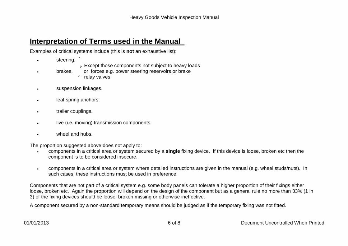
Examples of critical systems include (this is not an exhaustive list):
• steering. Except those components not subject to heavy loads
• brakes. or forces e.g. power steering reservoirs or brake relay valves.
• suspension linkages.
• leaf spring anchors.
• trailer couplings.
• live (i.e. moving) transmission components.
• wheel and hubs.
The proportion suggested above does not apply to:
• components in a critical area or system secured by a single fixing device. If this device is loose, broken etc then the component is to be considered insecure.
• components in a critical area or system where detailed instructions are given in the manual (e.g. wheel studs/nuts). In such cases, these instructions must be used in preference.
Components that are not part of a critical system e.g. some body panels can tolerate a higher proportion of their fixings either loose, broken etc. Again the proportion will depend on the design of the component but as a general rule no more than 33% (1 in 3) of the fixing devices should be loose, broken missing or otherwise ineffective. A component secured by a non-standard temporary means should be judged as if the temporary fixing was not fitted.

Heavy Goods Vehicle Inspection Manual
01/04/2015 7 of 8 Document Uncontrolled When Printed
Interpretation of Terms used in the Manual Obligatory Required to be fitted by law. Semi-trailer A trailer which is constructed or adapted to form part of an articulated vehicle. Trailer Where the term trailer is used in this manual it refers to all types of trailers and semi-trailers. Type Approved Vehicle A vehicle manufactured from 1 October 1982 and first used from 1 April 1983 and has been issued with a Type Approval Certificate of Conformity, a Ministers Approval Certificate or a Type Approval Certificate issued by an EU Member State. Type Approved A component or system fitted to a vehicle which has been issued with a Type Approval Certificate or Certificate of Conformity or built to an approval standard which shows that the system or component complies with the requirements of an EU Directive or ECE regulation. If the presenter claims that the vehicle is fitted with type approved equipment which complies with the requirements of an EC directive and has no documentary evidence, consideration must be given to the following:
• annual test standards should not exceed those of type approval • does the component or system appear to have been modified, replaced or damaged
Where doubt exists, the benefit should be given to the presenter. Vehicle Where the term vehicle is used in the application section of this manual it refers to all types of motor vehicle.
Heavy Goods Vehicle Inspection Manual
01/01/2013 8 of 8 Document Uncontrolled When Printed
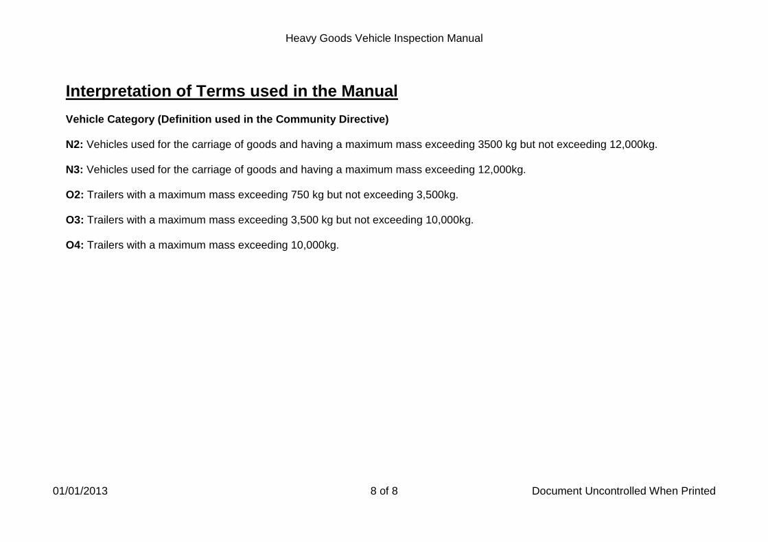
Interpretation of Terms used in the Manual Vehicle Category (Definition used in the Community Directive) N2: Vehicles used for the carriage of goods and having a maximum mass exceeding 3500 kg but not exceeding 12,000kg. N3: Vehicles used for the carriage of goods and having a maximum mass exceeding 12,000kg. O2: Trailers with a maximum mass exceeding 750 kg but not exceeding 3,500kg. O3: Trailers with a maximum mass exceeding 3,500 kg but not exceeding 10,000kg. O4: Trailers with a maximum mass exceeding 10,000kg.
Heavy Goods Vehicle Inspection Manual
01/01/2013 1 of 2 Document Uncontrolled When Printed
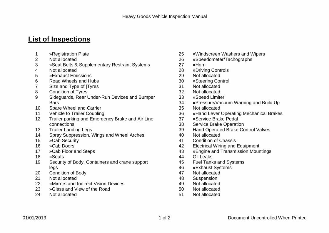
List of Inspections
1 »Registration Plate 2 Not allocated 3 »Seat Belts & Supplementary Restraint Systems 4 Not allocated 5 »Exhaust Emissions 6 Road Wheels and Hubs 7 Size and Type of |Tyres 8 Condition of Tyres 9 Sideguards, Rear Under-Run Devices and Bumper
Bars 10 Spare Wheel and Carrier 11 Vehicle to Trailer Coupling 12 Trailer parking and Emergency Brake and Air Line
connections 13 Trailer Landing Legs 14 Spray Suppression, Wings and Wheel Arches 15 »Cab Security 16 »Cab Doors 17 »Cab Floor and Steps 18 »Seats 19 Security of Body, Containers and crane support
legs 20 Condition of Body 21 Not allocated 22 »Mirrors and Indirect Vision Devices 23 »Glass and View of the Road 24 Not allocated
25 »Windscreen Washers and Wipers 26 »Speedometer/Tachographs 27 »Horn 28 »Driving Controls 29 Not allocated 30 »Steering Control 31 Not allocated 32 Not allocated 33 »Speed Limiter 34 »Pressure/Vacuum Warning and Build Up 35 Not allocated 36 »Hand Lever Operating Mechanical Brakes 37 »Service Brake Pedal 38 Service Brake Operation 39 Hand Operated Brake Control Valves 40 Not allocated 41 Condition of Chassis 42 Electrical Wiring and Equipment 43 »Engine and Transmission Mountings 44 Oil Leaks 45 Fuel Tanks and Systems 46 »Exhaust Systems 47 Not allocated 48 Suspension 49 Not allocated 50 Not allocated 51 Not allocated

Heavy Goods Vehicle Inspection Manual
01/01/2013 2 of 2 Document Uncontrolled When Printed
List of Inspections
52 Not allocated 53 Axles, Stub Axles and Wheel Bearings 54 Steering Mechanism 55 Not allocated 56 Not allocated 57 Transmission 58 Additional Braking Devices 59 Brake System and Components 60 Not allocated 61 Not allocated 62 Markers and Reflectors 63 Lamps 64 Not allocated 65 Not allocated 66 Direction Indicators and Hazard Warning Lamps 67 »Aim of Headlamp 68 Not allocated 69 Not allocated 70 Not allocated 71 Service Brake Performance 72 »Secondary Brake Performance 73 Parking Brake Performance 74 Other dangerous defects
» Inspection does not apply to trailers

Heavy Goods Vehicle Inspection Manual
01/01/2013 1 of 6 Document Uncontrolled When Printed
Standards for Prohibition Issue at Annual Test This provides a standard for the issue of Prohibition Notices where serious defects are observed during statutory tests. The aim of the policy is to:
• Protect the public from vehicles returning from annual test where extremely serious defects have been observed.
• Provide information about such occurrences to the enforcement wing of the organisation and to Traffic Commissioners.
• Improve the consistency of the treatment of operators.
• Let operators know the rules so that they know and understand the standards for prohibition issue at annual test.
• Preserve a balance between providing a flexible, customer focused, testing service and providing the general public with protection from loss or injury from vehicles returning from test with serious roadworthiness defects.
The approach, in principle, is to apply the immediate prohibition criteria in the Categorisation of Defects to a core of safety critical items. Note: Where a Reason for Failure in the accompanying table is marked with ** this means that any failure for this item will result in the issue of an immediate prohibition. Where a Reason for Failure is marked with * the examiner will need to assess the severity of the defect in line with the Categorisation of Defects criteria (outlined in the defects column of the table in the following pages) before deciding whether to issue an immediate prohibition.

Heavy Goods Vehicle Inspection Manual
01/01/2013 2 of 6 Document Uncontrolled When Printed
Standards for Prohibition (continued)
Manual Reference Defect Reason for Failure
IM 6 Road Wheels and
Hubs
More than one wheel nut/stud is missing loose or obviously not clamping or locating in the road wheel taper. Failure of the road wheel imminent. Detachment of a road wheel or hub imminent or a half shaft bolt, stud or nut missing.
2a* 2g* 3a*
IM8
Condition of Tyres
Tyre bulging caused by separation/failure of the tyre structure A tyre so severely damaged that failure of the tyre is likely Tyre tread worn below the legal minimum on tyre fitted to a steered wheel
1b** 1c* 1h*
IM11
Vehicle to Trailer Coupling
Failure of the coupling and detachment of the trailer likely
1c* 1e*

Heavy Goods Vehicle Inspection Manual
01/01/2013 3 of 6 Document Uncontrolled When Printed
Standards for Prohibition (continued)
Manual Reference Defect Reason for Failure
IM12 Trailer Parking,
Emergency Brakes and Air Line Connections
Parking brake does not operate on at least two road wheels Brake mechanism fractured or defective to such an extent that the brake is inoperative or cannot be set Trailer brakes are not applied when the emergency brake line is disconnected Adapter not fitted or providing inadequate lift to the extent that the correct operation of the brake is affected Tap fitted preventing correct operation of the braking system
1a** 1b** 2** 3b * 4**
IM 15
Cab Security
Driving control likely to be affected
1a**
IM18 Seats
A driver’s seat so insecure or in such a condition that it could cause the driver to lose control of the vehicle.
1*
IM28
Driving Controls
Driving control defective to the extent that it is incapable of fulfilling its function and affects the control of the vehicle
1e*
IM30
Steering Controls
Controls so defective that direction control of the vehicle is affected 1c*
1d* 2a*
IM34
Pressure/Vacuum Warning
Warning device fails to cease operating (indicating reservoirs not filling) – within 6 minutes for a rigid vehicle, 9 for vehicle/trailer combinations
3*

Heavy Goods Vehicle Inspection Manual
01/10/2014 4 of 6 Document Uncontrolled When Printed
Standards for Prohibition (continued)
Manual Reference Defect Reason for Failure
IM36 Hand Lever Operating
Mechanical Brakes
Cannot be operated to perform its function Cannot be set or likely to disengage
1d* 1f**
IM37
Service Brake Pedal
Cannot be operated to perform its function
1c* 2b*
IM38
Service Brake Operation
Vacuum assistance is not working
3a*
IM39
Hand Operated Brake Control Valve
Valve unable to be set in the on position or moved over its original full travel
1d* 1g*
IM44 Oil Leaks
Continuous flow of oil or serious risk of fire
1*
IM45
Fuel Tanks and Systems
Detachment of tank imminent Continuous fuel leak or a leak constituting a hazard to other road users Filler cap missing or defective such as to permit gushing
1** 2b** 3a* 4a** 4b** 4c**

Heavy Goods Vehicle Inspection Manual
01/01/2013 5 of 6 Document Uncontrolled When Printed
Standards for Prohibition (continued)
Manual Reference Defect Reason for Failure
IM48 Suspension
Imminent failure of a major suspension component which would affect the control of the vehicle
This item covers all Reasons for Failure. Examiners will need to consider will the defect affect the control of the vehicle.
IM53
Axles, stub axles and wheel bearings
A main component so defective that failure is imminent and likely to affect the steering
This item covers all Reasons for Failure. Examiners will need to consider will the defect affect the control of the vehicle
IM54
Steering Mechanism
Steering mechanism so stiff or rough in operation that its operation is restricted Mechanism fractured or twisted to the extent that failure or detachment is imminent
1a* 2a* 2i* 2j* 2o*
IM59
Brake Systems and Components
Any defect likely to lead to a total failure of a braking system
This item covers all Reasons for Failure. Examiners will need to consider will the defect affect the control of the vehicle
Heavy Goods Vehicle Inspection Manual
01/10/2014 6 of 6 Document Uncontrolled When Printed
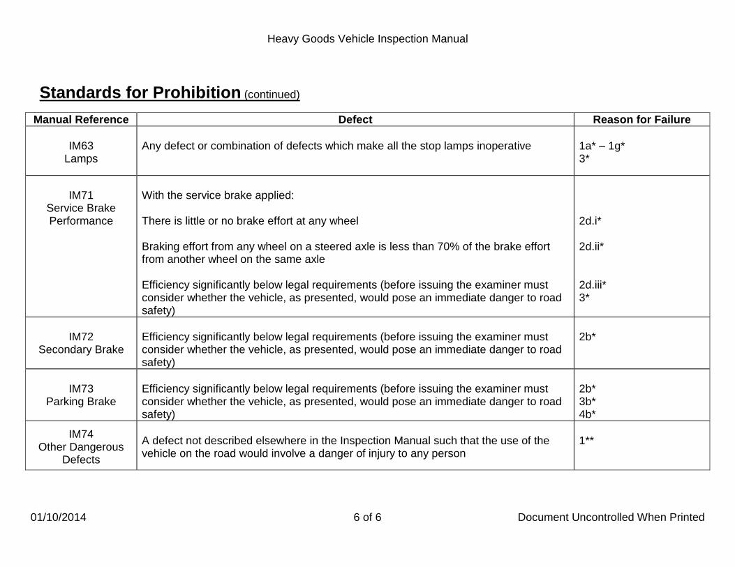
Standards for Prohibition (continued)
Manual Reference Defect Reason for Failure
IM63 Lamps
Any defect or combination of defects which make all the stop lamps inoperative
1a* – 1g* 3*
IM71
Service Brake Performance
With the service brake applied: There is little or no brake effort at any wheel Braking effort from any wheel on a steered axle is less than 70% of the brake effort from another wheel on the same axle Efficiency significantly below legal requirements (before issuing the examiner must consider whether the vehicle, as presented, would pose an immediate danger to road safety)
2d.i* 2d.ii* 2d.iii* 3*
IM72
Secondary Brake
Efficiency significantly below legal requirements (before issuing the examiner must consider whether the vehicle, as presented, would pose an immediate danger to road safety)
2b*
IM73
Parking Brake
Efficiency significantly below legal requirements (before issuing the examiner must consider whether the vehicle, as presented, would pose an immediate danger to road safety)
2b* 3b* 4b*
IM74
Other Dangerous Defects
A defect not described elsewhere in the Inspection Manual such that the use of the vehicle on the road would involve a danger of injury to any person
1**

Heavy Goods Vehicle Inspection Manual
01/07/2013 1 of 1 Document Uncontrolled When Printed
01 Registration Plate Application
This inspection applies to all registered motorised vehicles.
A registration plate should be easily legible to a person standing approximately 20m from the front/rear of the vehicle.
Method of Inspection Reason for Failure
1. Check that there is a registration plate at both the front and the rear of the vehicle, and check each
a. presence. one for:
b. security.
2. Check the registration mark for: a. presence. b. legibility.
1. A registration plate:
a. missing. b. insecure.
2. A registration mark: a. missing. b. illegible.

Heavy Goods Vehicle Inspection Manual
01/10/2013 1 of 5 Document Uncontrolled When Printed
03 Seat Belts & Supplementary Restraint Systems Application
This inspection applies to all vehicles with seat belts and/or Supplementary restraint systems (SRS) fitted.
The minimum requirement for the fitment of seat belts is detailed in the tables below.
The only goods vehicles up to and including 3500kg DGW likely to be subject to this inspection are mini-articulated vehicles.
Driver’s seat
Minimum Requirements for Forward Facing Seats on Vehicles First Used from 1 October 2001 with A DGW in Excess of 3500kg
Front passenger seats Rear passenger seats
3 point belt (lap and diagonal) or lap belt
3 point belt (lap and diagonal), lap belt or disabled person’s belt
No belt required
Vehicle first used:
Vehicles First Used from 1 April 1980 up to and Including 3500kg DGW
Driver’s and specified front passenger seat (furthest from driver)
Other front passengers Rear passengers
1/4/1980 to 31/3/1981 2 point belt (diagonal body restraining)
No belt required No belt required
1/4/1981 to 31/3/1987 3 point belt (lap and diagonal
No belt required No belt required
From 1/04/1987 3 point belt (lap and diagonal)
3 point belt (lap and diagonal), lap belt or disabled person’s belt
No belt required

Heavy Goods Vehicle Inspection Manual
01/10/2014 2 of 5 Document Uncontrolled When Printed
03 Seat Belts & Supplementary Restraint Systems Application
Seat belts are not required on light goods vehicles with an ULW exceeding 1525kg, if the model of vehicle was first manufactured before 1 October 1979 and the vehicle was manufactured before 1 October 1981, or first used before 1 April 1982.
For seats with integral seat belts, it may not be possible to examine the fixing of the seat belt to the seat.
On retracting seat belts, check that with the mechanism fastened and the seat adjusted to its rearmost position, excess webbing is wound into the retracting unit. If there is doubt about the operation of the retracting unit, this check should be carried out with the seat unoccupied.
Some types of retracting belt might need manual help before they retract.
Operate the release mechanism while pulling on the belt to check that the mechanism releases when required.
Pull the sheaths aside if this can be done without damage
Some vehicles have seat belts which will not release the inertia aspect of the seat belt unless the ignition is switched on. Ensure the park brake is applied and the gears are in the neutral position before switching on the ignition. Owing to the height of cabs on many commercial vehicles this inspection should be performed with the inspector sat in the appropriate seat.
Floor mounted anchorages may need to be inspected from underneath the vehicle.
Where a belt is fitted with no corresponding seat or if there is a buckle/stalk but no corresponding belt, it is NOT to be considered a seat belt
The inspection of Supplementary Restraint Systems (SRS) applies to airbags, seat belt pre-tensioners and seat belt load limiters when fitted as standard.
for the purpose of this inspection.

Heavy Goods Vehicle Inspection Manual
01/10/2014 3 of 5 Document Uncontrolled When Printed
03 Seat Belts & Supplementary Restraint Systems Application
The SRS malfunction indicator lamp (MIL) may display a symbol similar to that below, one depicting a person wearing a seat belt.or alternatively the letters ‘SRS’.
A passenger air bag which has been switched off is not a reason for failure. Seat belt load limiters are used on some vehicles to minimise seat belt inflicted injury in particularly violent collisions. This is generally achieved by releasing a little more excess belt webbing when a great deal of force is applied to the belt. The simplest type of load limiter is a fold
More advanced load limiters rely on a torsion bar in the retractor mechanism, which cannot usually be readily seen or tested.
sewn into the belt webbing. The stitches holding the fold in place are designed to come apart when a high amount of force is applied to the belt, thereby releasing an extra bit of webbing.
Seat belt pre-tensioners may be fitted to some seat belts. Once activated a warning device may display.
Method of Inspection Reason for Failure
1. Check Obligatory Seat Belts: a. for presence. b. are of the correct type.
Check the condition of all seat belts fitted. 2. Anchorages:
a. without dismantling check there is no excessive corrosion, serious deterioration or a fracture within 300mm (12”) of the anchorage (where a seat belt is attached to a seat frame this will apply to all seat mounting points).
b. check seat belt/s are securely fixed to the seat or to the
vehicle structure.
1. Obligatory Seat Belt (see Table): a missing. b of an incorrect type.
2. Anchorages:
a. with excessive corrosion, serious deterioration or a fracture in a load bearing member of the vehicle structure within 300mm (12”) of the anchorage (where a seat belt is attached to a seat frame this will apply to all seat mounting points).
b. a seat belt not securely fixed to the seat or to the vehicle
structure.

Heavy Goods Vehicle Inspection Manual
01/01/2013 4 of 5 Document Uncontrolled When Printed
03 Seat Belts & Supplementary Restraint Systems Method of Inspection Reason for Failure
3. Check Locking Mechanism, Stalks, Retracting Mechanism
and Fittings. Fasten each belt locking mechanism and try and pull the locked sections apart:
a. check the locking mechanism of the seat belt/s secure and
release as intended. b. check the attachment and adjustment fitting for fractures,
deterioration and that it is operating effectively. c. check the flexible stalk is free from corrosion or deterioration
likely to lead to failure under load. d. check there are no broken flexible stalk strands. e. check the retracting mechanism retracts the webbing
sufficiently to remove all the slack from the belt with the locking mechanism fastened.
4. Check that the Webbing:
a. has no cut which causes the fibres to separate. b. has no fluffing or fraying sufficient to obstruct correct operation
of the belt or which has clearly weakened the webbing. c. has no stitching badly frayed, is secure, complete and has not
been repaired.
3. Locking Mechanism, Stalks, Retracting Mechanism and
Fittings:
a. locking mechanism of a seat belt does not secure or release as intended.
b. an attachment or adjustment fitting fractured, badly
deteriorated or not operating effectively. c. corrosion or deterioration of a flexible stalk likely to lead to
failure under load. d. broken flexible stalk strands. e. a retracting mechanism does not retract the webbing
sufficiently to remove all the slack from the belt with the locking mechanism fastened.
4. Condition of Webbing:
a. a cut which causes the fibres to separate. b. fluffing or fraying sufficient to obstruct correct operation of the
belt or which has clearly weakened the webbing. c. stitching badly frayed, insecure, incomplete or repaired.

Heavy Goods Vehicle Inspection Manual
20/03/2013 5 of 5 Document Uncontrolled When Printed
03 Seat Belts & Supplementary Restraint Systems Method of Inspection Reason for Failure
5. Check for obvious signs of structural weakness such that failure
is likely in, seat belt; fittings, guides, stalks or pivots. 6. Check seats with seat belts attached to them for:
a. security. b. there are no cracks or fractures in the leg or frame.
7. Check the presence and condition of any seat belt load limiters and/or pretensioners fitted as original equipment.
8. As far as practicable, check that: a. all driver and passenger airbags fitted as original equipment, are present and b. are not obviously defective.
9. Check the SRS warning light does not indicate a fault.
5. Obvious signs of structural weakness in a Seat belt; fitting,
guide,stalk or pivot such that failure is likely. 6. Seats with seat belts attached to them:
a. insecure. b. with a cracked or fractured leg or frame.
7. A seat belt: a. load limiter or pretensioner obviously missing where fitted
as original equipment. b. pretensioner or a ‘folded type’ webbing load limiter
obviously deployed. 8. An airbag:
a. missing.
b. obviously defective. 9. The SRS warning lamp indicates any kind of failure in the
system.

Heavy Goods Vehicle Inspection Manual
01/01/2013 1 of 5 Document Uncontrolled When Printed
05 Exhaust Emissions Application
This inspection applies to all Diesel and other Compression Ignition engine vehicles. For Hybrid Electric Vehicles see below ninth bullet point.
Diesel and other Compression Ignition Engines: • Exhaust emissions must be tested using an approved and calibrated smoke meter.
• Only in exceptional circumstances where it is not possible to use a smoke meter will a visual check be carried out. Visual tests will not apply to Fast Pass or vehicles submitted for Reduced Pollution Certification.
• If the exhaust has been deliberately modified to prevent the smoke meter from being used a VTG 12 must be issued refusing to complete the test because the exhaust smoke emissions test cannot be carried out.
• Twin exhaust systems, without a balance pipe - both systems must be individually tested for smoke emissions. It may be necessary to purge the exhaust system again prior to the second check.
• Supercharged engines should be tested by selecting the non-turbocharged option on the smoke meter.
• The test procedure for turbocharged and non-turbocharged engines is the same.
• It is not normally sufficient to run the engine with the vehicle stationary to warm it up to temperature, so the emissions should be tested as soon as possible after the vehicle arrives at the test station.
• With some types of smoke meter care must be taken to ensure that the probe is correctly aligned to the exhaust gas flow (reference to meter manufacturer’s instruction may be necessary).
• HEVs do not require a metered smoke test or a visual smoke test as described in MOI 2. However where there is a supplementary engine used, this should be observed that it does not emit excessive smoke. If excessive smoke is observed this is a RfF under item 2b.

Heavy Goods Vehicle Inspection Manual
01/01/2013 2 of 5 Document Uncontrolled When Printed
05 Exhaust Emissions Application
Some diesel smoke meters (DSM) may fail to trigger a reading when testing modern vehicles fitted with low emission diesel engines which produce very low levels of smoke. If the smoke meter does not register a reading or shows an error reading follow step one or two below as appropriate:
1. If the DSM produces a print out, this should be marked showing that the emissions limits were tested and met but the DSM could not register the reading. This should be attached to the test card in the normal way.
2. If the DSM will not produce a printout, the tester should make a note on the bottom of the test card stating that the emissions limits were tested and met but the DSM could not register the reading.
Air Fuel Ratio Control (AFRC) fitted to Caterpillar engines. When the engine is stopped the control goes into an excess fuel position. When the engine is restarted the inlet manifold pressure necessary to reset the AFRC into its normal running position is normally greater than that generated during the free acceleration test. Vehicles should therefore either be checked at the start of the test if the engine has not been stopped or at the end of the test where the vehicle should be driven on the test track against the load of a partially applied brake sufficient to reset the AFRC prior to conducting the test.
If a vehicle fails the test because the exhaust is holed the emissions must be rechecked when the vehicle is retested.
Remember to issue a printout.

Heavy Goods Vehicle Inspection Manual
01/01/2013 3 of 5 Document Uncontrolled When Printed
05 Exhaust Emissions Method of Inspection Reason for Failure
1. Free acceleration test using smoke meter 1a.
i. Check that the engine is at or near normal operating temperature.
ii. Purge the inlet and exhaust systems fully by holding the engine speed steady at just below maximum governed speed for 30 seconds.
iii. Select the appropriate test programme on the smoke meter. iv. Follow the meter prompts; depress the accelerator pedal
quickly but not violently, to reach full fuel position in less than 1 second. Hold it there until a release prompt is given. If, at the end of the 1st acceleration, the smoke meter value is no more than 1.50m-1
v. If the 1
the vehicle will have met the fast pass limit.
st meter reading is more than 1.50m-1
vi. For vehicles first registered from 1 July 2008. If they fail the fast pass test you will need to choose the most appropriate programme for the meter to perform a full metered smoke test, should the meter only allow 3 accelerations you may need to repeat the exercise to gain the 6 accelerations required and then look for 3 consecutive results from both printouts before deciding whether the vehicle should pass or fail (It is recommended that RPC4 is chosen for this operation).
further accelerations will be required, following meter prompts, up to a maximum of 6 accelerations.
1b. Assess visually whether the smoke emitted from the exhaust regardless of the measured density, is likely to obscure the vision of other road users.
1. Statutory Smoke Meter Test 1a.
After a total of six accelerations have been completed, the average smoke opacity recorded for accelerations 4, 5 and 6 is more than: For vehicles registered prior to 1 July 2008:
• 2.5m-1
• 3.0m
for non-turbocharged engines -1
For vehicles first registered from 1 July 2008: for turbocharged engines.
• 1.5m-1
for all diesel engines.
1b. The exhaust emits excessive smoke or vapour of any colour, to an extent likely to obscure vision.

Heavy Goods Vehicle Inspection Manual
16/02/2014 4 of 5 Document Uncontrolled When Printed
05 Exhaust Emissions Method of Inspection Reason for Failure
2. Visual emission test 2a.
i. Only in exceptional circumstances where it is not possible to use a smoke meter will a visual check be carried out. The visual test is only to be used when it is not possible to use the smoke meter or where risk to health and safety would arise. The procedure is the same for supercharged, turbocharged and non-turbocharged engines.
ii. With the engine at or near normal operating temperature check the density of the exhaust emission visually.
iii. Ask the driver to depress the accelerator pedal quickly but not violently, to reach full fuel position in less than 1 second. Immediately release when the engine reaches its maximum governed speed, allow the engine to return to idle speed.
iv. Ignore smoke from the first acceleration. v. Repeat up to a maximum of six times if necessary until the
exhaust smoke is considered to be acceptable for two successive accelerations.
2b. Assess whether the smoke emitted from the exhaust, regardless of the measured density, is likely to obscure the vision of other road users.
3. Check the vehicle for presence of emission control systems fitted as standard.
2. Statutory visual test 2a.
After a maximum of six accelerations the exhaust emits smoke of a level greater than that of equivalent metered levels.
2b. The exhaust emits excessive smoke or vapour, of any colour, to an extent likely to obscure vision.
Note: The criterion is density and not volume of smoke. The description `dense smoke’ includes any smoke or vapour which largely obscures vision.
3. A Catalytic converter, particulate filter or selective catalytic reduction system missing where it was fitted as standard.

Heavy Goods Vehicle Inspection Manual
01/01/2013 5 of 5 Document Uncontrolled When Printed
05 Exhaust Emissions Method of Inspection
Reduced Pollution Certificate (RPC) Smoke meter test The RPC check is not part of the statutory test requirement.
1. Select appropriate RPC limit. Carry out Method of Inspections listed at 1.a procedures I, II and III only. 2. Following meter prompts carry out three acceleration tests. Depress the accelerator pedal quickly but not violently, to reach full
fuel position in less than 1 second. Hold it there until a release prompt is given. At the end of the 3rd
acceleration the smoke meter will display the average smoke value and test result. If the RPC value is not met and the meter readings are above the statutory limits, further accelerations up to a maximum of six may be prompted by the meter.
A vehicle will pass the RPC metered test if the opacity level is no greater than:
0.2m-1 for all vehicles fitted with a particulate
0.4mtrap.
-1
0.8m vehicles fitted with an unmodified Euro -2 engine.
-1
1.0m vehicles fitted with an unmodified Euro -1 engine.
-1
vehicles retro-fitted with a Euro -2 engine.

Heavy Goods Vehicle Inspection Manual
01/01/2013 1 of 4 Document Uncontrolled When Printed
06 Road Wheels and Hubs Application
This inspection applies to all road wheels and hubs apart from spare wheels. Where possible wheel nuts will be lightly tapped with a hammer to check for looseness, but any other evidence such as rust marks or elongation of bolt/stud holes must also be taken into account. A nut or stud is considered to be “loose” if it is not obviously carrying out its function of clamping the wheel to the hub. With some vehicles it is not possible to see the road wheels completely from ground level, especially with twin wheels and where the body hides part of the wheels. In such cases the vehicle must be moved to expose hidden parts of the wheels, or examined from underneath. Whenever possible, presenters should remove wheel embellishers; remove visual security indicators, if they prevent a full examination. Where this can not be accomplished, continue to inspect the vehicle and annotate the test card to state that the embellishers were not removed. Capacity Limitations of 11.75 x 22.5 Alcoa Aluminium Wheels.
Wheels with the part number 813520/813523 may be stamped on the inside of the wheel, opposite the valve, with a maximum load rating of 4250kg or 4500kg and those with part number 813530/813533 with a rating of 4500kg. It has been agreed that wheels with these part numbers and maximum load ratings are suitable for a maximum axle weight of 9150kg.
Kronprinz wheels fitted to the Volvo FL L 4x2 rigid and FL 6H 4x2 rigid, are capable of carrying higher loads than those shown on the wheels. The wheels can be identified by the following markings stamped on the wheel: Wheel brand name Kronprinz Clamping type M20 Place of manufacture Made in France Designation 19.5 x 7.50HOS56 E-DOT Wheel load index 144/142 Volvo part number 20946506 The wheel is capable of carrying a load equatable to a 145/143. Please be aware of the increased load capacity should you observe these wheels at annual test. This weight increase is applicable to all vehicles equipped with these wheels not just Volvo.

Heavy Goods Vehicle Inspection Manual
01/01/2013 2 of 4 Document Uncontrolled When Printed
06 Road Wheels and Hubs Application
Capacity limitation of a wheel marked with a load index If a wheel is marked with a load index which indicates that the maximum load is lower than is required to support the axle load, the vehicle should be failed under Reason for Failure 2.i. Wheels not marked with a load index or load marking must be assumed to be capable of carrying the axle weight. Compatibility of Wheel Fixings
Vehicles with conical wheel fixings MUST NOT be fitted with wheels from vehicles designed for use with spherical fixings. (British built vehicles normally have conical wheel fixings). Vehicles with spherical wheel fixings MUST NOT be fitted with wheels from vehicles which are designed for use with conical fixings. Volvo wheels of the original spigot-mounting design WILL NOT interchange with another type. Volvo wheels designed for later type spigot mounting may be used in an emergency on British built trailers.
Wheels with conical fixings MUST NOT be used on Volvo vehicles because they do not have a machine centre bore to fit hub

Heavy Goods Vehicle Inspection Manual
01/01/2013 3 of 4 Document Uncontrolled When Printed
06 Road Wheels and Hubs Application
Sleeved two piece flange nut fixing
Sleeved two piece flange nut fixing, this fixing method of utilising a sleeved nut has been adopted primarily to allow the retro fitting of aluminium wheels which incorporate a thicker flange.
Where wheel trim brackets are secured by the wheel retaining nuts it is acceptable provided the bracket does not stop the wheel nut from seating correctly in the taper of the stud hole. For spigot mounted wheels there may be some overlap between the washer and bracket, failure will only be justified where the nut clamping force is obviously ineffective.
Some wheel nut studs do not protrude all the way through the wheel nut this is acceptable provided there is no sign of insecurity.
Where twin wheels are fitted the spigots must extend to the outer wheel to locate this.

Heavy Goods Vehicle Inspection Manual
01/01/2013 4 of 4 Document Uncontrolled When Printed
06 Road Wheels and Hubs Method of Inspection Reason for Failure
1. Check tyre retaining rings for:
a. fractures. b. clearance, (butting of the ends is acceptable with lift on the
flange up to 1.5mm from the rim). 2. Check all road wheels for:
a. presence, security and function of all retaining nuts and studs.
b. elongation of a stud hole. c. the condition of spigot wheel nut washers.
d. damage or distortion and the presence of the locating spigot
or dowel. e. damage caused by wheel nuts f. compatible fixings. g. condition, cracks (except at the bridge over the valve), welds
and repairs. h. repairs by welding to aluminium alloy wheels.
i. the correct load rating that is required to support the maximum permissible (GB) axle load.
3. Check hubs for: a. condition, and that the half shaft bolts, studs or nuts are
secure.
b. clearance between a spigot mounted wheel and the hub spigots.
1. A tyre retaining ring:
a. fractured. b. butting causing the flange to lift more than 1.5mm from the
rim. 2. A wheel:
*a. nut or stud missing or loose or obviously not fulfilling the function of clamping the wheel to the hub.
b. with any visible elongation of a stud hole.
c. with a spigot wheel nut washer cracked.
d. badly damaged or distorted or with a locating spigot or
dowel missing. e. damaged by the corners of a wheel nut cutting into the
material of the wheel.
f. and its fixings not compatible.
*g. cracked (except at the bridge over the valve), weld breaking away or an inadequate repair.
h. made of aluminium alloy repaired by welding.
i. with a load rating less than that required to support the maximum permissible (GB) axle load.
3. A hub: *a. cracked, badly damaged, or with a half shaft bolt, stud or
nut loose or missing.
b. with clearance between a spigot mounted wheel and the hub spigots that exceeds 3mm across the diameter.

Heavy Goods Vehicle Inspection Manual
01/04/2015 1 of 14 Document Uncontrolled When Printed
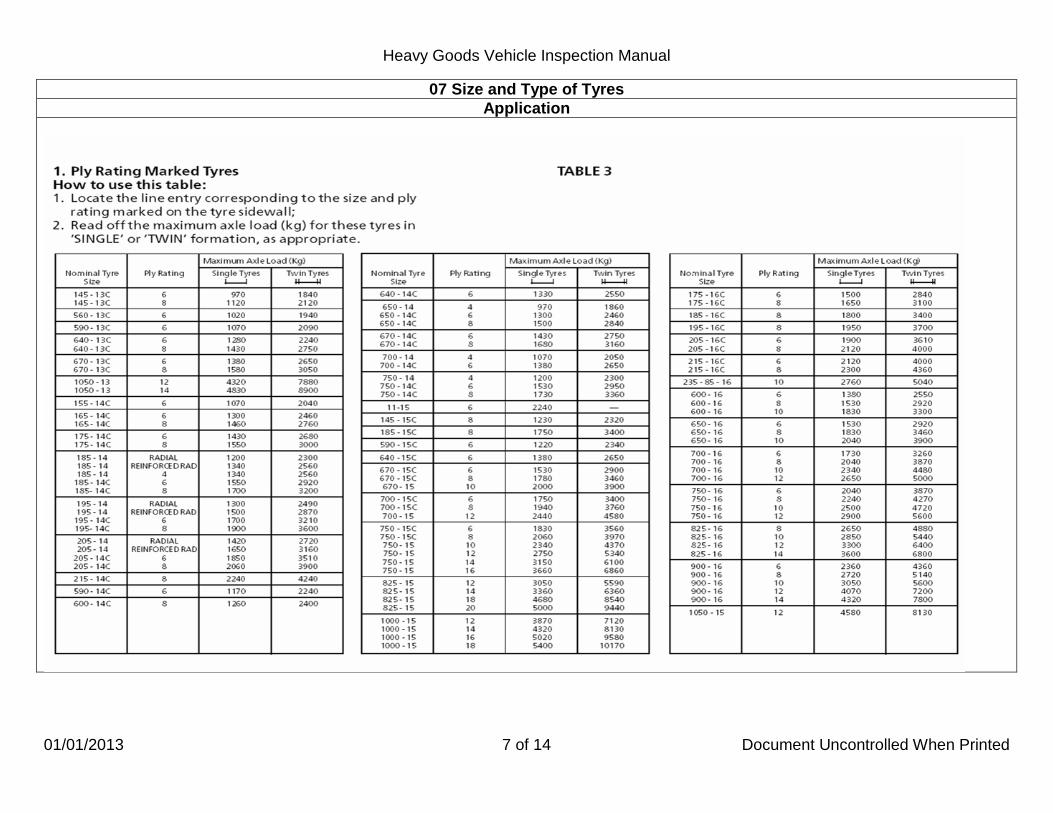
07 Size and Type of Tyres Application
This inspection applies to all tyres, apart from spare tyres. The use markings most likely to be encountered are "FRT" which indicates that the tyre is not suitable for use on a driven axle and "TRAILER USE ONLY". Tyres marked with a direction arrow pointing in the wrong direction should not be failed. Tyres are usually identified by their nominal section size followed by the rim diameter e.g. 10.00-20,750-16, etc (the majority of modern tyres carry millimetric markings e.g. 205-16 etc). For identification of sidewall markings refer to the diagram at the end of this section. All tyres on an axle must be of the same nominal size. If a tyre is dual marked one of the markings must be the same as the markings on the other tyres on the axle. There are still a number of high load capacity tyres in use which are marked with a code to indicate the tyre size and capacity e.g. a 10.00-20 16 ply tyre may be marked D20 or 4-20 (a full list of these tyres is given at Table 1). If tyres marked with a load capacity index are fitted the maximum permissible axle Load for normal use can be found in Table 2 at the end of this section. The Load Index (LI) may consist of one or two numbers e.g. 154 or 146/143. Where two numbers are displayed the first refers to the use of the tyre in single formation and the second in twin formation. Reference to the table shows that the maximum loads for this tyre are 6000kg in single formation and 10900 in twin formation. If a load index is not shown the carrying capacity of a tyre can be determined from the Ply Rating. The load capacity of ply rated tyres is shown at Table 3. If no ply rating can be found on the tyre it should be assumed to have the lowest load capacity listed for that size of tyre. This information relates to tyres used without any restriction (i.e. with tyre use symbol 2B indicated on the plate or plating certificate). There are three other categories of vehicle use which allow tyres to be operated at lower speeds and higher loads. The details of the axle loads are in the Tyre Tables obtainable from the Driver and Vehicle Standards Agency, Ellipse, Padley Road, Swansea SA1 8AN.

Heavy Goods Vehicle Inspection Manual
01/01/2013 2 of 14 Document Uncontrolled When Printed
07 Size and Type of Tyres Application
2J SPEED RESTRICTED TO 40MPH This category is applicable to “Municipal vehicles”. “Municipal vehicles” means a motor vehicle or trailer limited at all times to use by a local authority, or a person acting in pursuance of a contract with a local authority, for road cleansing, road watering or the collection and disposal of refuse, night soil or the contents of cesspools, or the purposes of the enactments relating to weights and measures or the sale of food and drugs: OR “Multi-stop local collection and delivery vehicles” being a motor vehicle or trailer used for multi-stop collection and delivery services to be used only within a radius of 25 miles from the permanent base at which it is normally kept. 2M SPEED RESTRICTED TO 40MPH This category is applicable to a “low platform trailer” being a trailer fitted with tyres with a rim diameter size code of less than 20 and displaying a rectangular plate which is at least 225mm wide and at least 175mm high and bears two black letters “L’’ at least 125mm high and 90mm wide with a stroke width of 12mm. 2R SPEED RESTRICTED TO 50MPH This category is applicable to any vehicle which displays a “50’’ plate in accordance with Schedule 13 of the C & U regulations. SPEED SYMBOLS The speed capability is represented by a letter which is displayed adjacent to the LI marking e.g. 146/143J. This indicates the speed at which the tyre can carry the load(s) indicated by the LI marking(s). In the above example the tyres carry a load of 6000/10900kg at 62mph. The minimum required speed ratings are :
CLASS OF VEHICLE PERMITTED SPEED (MPH) MINIMUM SPEED SYMBOL Rigid goods vehicles with maximum laden weight not exceeding 7.5 tonnes
70
L Rigid goods vehicles with maximum laden weight exceeding 7.5 tonnes
60 J
Articulated vehicles 60 J Trailers 60 J
Goods vehicles and trailers operating under 2J or 2M tyre use conditions 40 D Restricted speed vehicles operating under 2R tyre use conditions 50 F

Heavy Goods Vehicle Inspection Manual
01/01/2013 3 of 14 Document Uncontrolled When Printed
07 Size and Type of Tyres Application
ALTERNATIVE SPEED RATINGS Certain vehicles can be fitted with tyres showing a lower speed rating than those shown above but the maximum axle loads will be reduced as shown below.
CLASS OF VEHICLE NORMAL SPEED RATING ALTERNATIVE SPEED RATING
REDUCTION IN AXLE LOADS
Motor vehicle not exceeding 7500kg plated
weight
L
J 7% K 3%
Trailers
J
F 15% G 5%
Details of the reduced axle loads which tyres can carry are shown in Table 4.
STRUCTURE Examine all the tyres fitted and note the type of structure (radial, cross-ply or bias-belted) and the nominal size of tyres. All tyres on an axle must be of the same structure and nominal size. Tyres on an axle may be of different structures and nominal sizes to those on another axle with the following exceptions:
• All tyres on all steered axles must have the same structure. • All tyres on all driven axles must have the same structure. • On two axle motor vehicles where each axle is fitted with single wheels, if all the tyres are not of the same structure, the type of
structure which is allowed to be fitted to each axle is shown in the table.
Axle 1 Axle 2 Cross-ply Bias-belted Cross-ply Radial
Bias-belted Radial
This does not apply to an axle on which wide single tyres with a road contact width of more than 300mm are fitted.

Heavy Goods Vehicle Inspection Manual
01/01/2013 4 of 14 Document Uncontrolled When Printed
07 Size and Type of Tyres Application

Heavy Goods Vehicle Inspection Manual
01/04/2015 5 of 14 Document Uncontrolled When Printed
07 Size and Type of Tyres Application
Table 2 Load capacity index table Extract from ECE Reg 54: “Load index” Table amended to show axle loads
Load Index
Single Kg
Dual Kg
Load Index
Single Kg
Dual Kg
Load Index
Single Kg
Dual Kg
70 71 72 73 74 75 76 77 78 79
80 81 82 83 84 85 86 87 88 89
90 91 92 93 94 95 96 97 98 99
670 690 710 730 750 774 800 824 850 874
900 924 950 974
1000 1030 1060 1090 1120 1160
1200 1230 1260 1300 1340 1380 1420 1460 1500 1550
1340 1380 1420 1460 1500 1548 1600 1648 1700 1748
1800 1848 1900 1948 2000 2060 2120 2180 2240 2320
2400 2460 2520 2600 2680 2760 2840 2920 3000 3100
100 101 102 103 104 105 106 107 108 109
110 111 112 113 114 115 116 117 118 119
120 121 122 123 124 125 126 127 128 129
1600 1650 1700 1750 1800 1850 1900 1950 2000 2060
2120 2180 2240 2300 2360 2430 2500 2570 2640 2720
2800 2900 3000 3100 3200 3300 3400 3500 3600 3700
3200 3300 3400 3500 3600 3700 3800 3900 4000 4120
4240 4360 4480 4600 4720 4860 5000 5140 5280 5440
5600 5800 6000 6200 6400 6600 6800 7000 7200 7400
130 131 132 133 134 135 136 137 138 139
140 141 142 143 144 145 146 147 148 149
150 151 152 153 154 155 156 157 158 159
3800 3900 4000 4120 4240 4360 4480 4600 4720 4860
5000 5150 5300 5450 5600 5800 6000 6150 6300 6500
6700 6900 7100 7300 7500 7750 8000 8250 8500 8750
7600 7800 8000 8240 8480 8720 8960 9200 9440 9720
10000 10300 10600 10900 11200 11600 12000 12300 12600 13000
13400 13800 14200 14600 15000 15500 16000 16500 17000 17500

Heavy Goods Vehicle Inspection Manual
01/01/2013 6 of 14 Document Uncontrolled When Printed
07 Size and Type of Tyres Application
Table 2 Continued Load capacity index table Extract from ECE Reg 54: “Load index” Table amended to show axle loads
Load Index
Single Kg
Dual Kg
Load Index
Single Kg
Dual Kg
Load Index
Single Kg
Dual Kg
160 161 162 163 164 165 166 167 168 169
170 171 172 173 174 175 176 177 178 179
9000 9250 9500 9750 10000 10300 10600 10900 11200 11600
12000 12300 12600 13000 13400 13800 14200 14600 15000 15500
18000 18500 19000 19500 20000 20600 21200 21800 22400 23200
24000 24600 25200 26000 26800 27600 28400 29200 30000 31000
Heavy Goods Vehicle Inspection Manual
01/01/2013 7 of 14 Document Uncontrolled When Printed
07 Size and Type of Tyres Application

Heavy Goods Vehicle Inspection Manual
01/01/2013 8 of 14 Document Uncontrolled When Printed
07 Size and Type of Tyres Application
TABLE 3 (continued)

Heavy Goods Vehicle Inspection Manual
01/01/2013 9 of 14 Document Uncontrolled When Printed
07 Size and Type of Tyres Application
TABLE 4 MAX AXLE LOADS FOR “UNRESTRICTED” SPEED VEHICLES Tyre load
Index Trailers permitted to exceed 50mph
(up to 60mph) Motor vehicles permitted to exceed 60mph
(up to 70mph) Speed Symbol
F (-15%) Speed Symbol
G (-5%) Speed Symbol
J (-7%) Speed Symbol
K (-3%) Single Kg Dual Kg Single Kg Dual Kg Single Kg Dual Kg Single Kg Dual Kg
70 71 72 73 74 75 76 77 78 79 80 81 82 83 84 85 86 87 88 89 90 91 92 93 94 95 96 97 98
570 590 610 630 640 660 680 700 730 750 770 790 810 830 850 880 910 930 960 990
1020 1050 1080 1110 1140 1180 1210 1250 1280
1140 1180 1210 1250 1280 1320 1360 1410 1450 1490 1530 1580 1620 1660 1700 1760 1810 1860 1910 1980 2040 2100 2150 2210 2280 2350 2420 2490 2550
640 660 680 700 720 740 760 790 810 830 860 880 910 930 950 980
1010 1040 1070 1110 1140 1170 1200 1240 1280 1320 1350 1390 1430
1280 1320 1350 1390 1430 1480 1520 1570 1620 1670 1710 1760 1810 1860 1900 1960 2020 2080 2130 2210 2280 2340 2400 2470 2550 2630 2700 2780 2850
630 650 660 680 700 720 750 770 800 820 840 860 890 910 930 960 990
1020 1050 1080 1120 1150 1180 1210 1250 1290 1330 1360 1400
1250 1290 1330 1360 1400 1440 1490 1540 1590 1630 1680 1720 1770 1820 1860 1920 1980 2030 2090 2160 2240 2290 2350 2420 2500 2570 2650 2720 2790
650 670 690 710 730 760 780 800 830 850 880 900 930 950 970
1000 1030 1060 1090 1130 1170 1200 1230 1270 1300 1340 1380 1420 1460
1300 1340 1380 1420 1460 1510 1560 1600 1650 1700 1750 1800 1850 1890 1940 2000 2060 2120 2180 2250 2330 2390 2450 2530 2600 2680 2760 2840 2910

Heavy Goods Vehicle Inspection Manual
01/01/2013 10 of 14 Document Uncontrolled When Printed
07 Size and Type of Tyres Application
TABLE 4 (continued) MAX AXLE LOADS FOR “UNRESTRICTED” SPEED VEHICLES Tyre load
Index Trailers permitted to exceed 50mph
(up to 60mph) Motor vehicles permitted to exceed 60mph
(up to 70mph) Speed Symbol
F (-15%) Speed Symbol
G (-5%) Speed Symbol
J (-7%) Speed Symbol
K (-3%) Single Kg Dual Kg Single Kg Dual Kg Single Kg Dual Kg Single Kg Dual Kg
99 100 101 102 103 104 105 106 107 108 109 110 111 112 113 114 115 116 117 118 119 120 121 122 123 124 125
1320 1360 1410 1450 1490 1530 1580 1620 1660 1700 1760 1810 1860 1910 1960 2010 2070 2130 2190 2250 2320 2380 2470 2550 2640 2720 2810
2640 2720 2810 2890 2980 3060 3150 3230 3320 3400 3510 3610 3710 3810 3910 4020 4140 4250 4370 4490 4630 4760 4930 5100 5270 5440 5610
1480 1520 1570 1620 1670 1710 1760 1810 1860 1900 1960 2020 2080 2130 2190 2250 2310 2380 2450 2510 2590 2660 2760 2850 2950 3040 3140
2950 3040 3140 3230 3330 3420 3520 3610 3710 3800 3920 4030 4150 4260 4370 4580 4620 4750 4890 5020 5170 5320 5510 5700 5890 6080 6270
1450 1490 1540 1590 1630 1680 1730 1770 1820 1860 1920 1980 2030 2090 2140 2200 2260 2330 2390 2460 2530 2610 2700 2790 2890 2980 3070
2890 2980 3070 3170 3260 3350 3450 3540 3630 3720 3840 3950 4060 4170 4280 4390 4520 4650 4780 4910 5060 5210 5400 5580 5770 5960 6140
1510 1560 1610 1650 1700 1750 1800 1850 1900 1940 2000 2060 2120 2180 2240 2290 2360 2430 2500 2570 2640 2720 2820 2910 3010 3110 3210
3010 3110 3210 3300 3400 3500 3590 3690 3790 3880 4000 4120 4230 4350 4470 4580 4720 4850 4990 5130 5280 5440 5626 5820 6020 6210 6410

Heavy Goods Vehicle Inspection Manual
01/01/2013 11 of 14 Document Uncontrolled When Printed
07 Size and Type of Tyres
Application TABLE 4 (continued) MAX AXLE LOADS FOR “UNRESTRICTED” SPEED VEHICLES
Tyre load Index
Trailers permitted to exceed 50mph (up to 60mph)
Motor vehicles permitted to exceed 60mph (up to 70mph)
Speed Symbol F (-15%)
Speed Symbol G (-5%)
Speed Symbol J (-7%)
Speed Symbol K (-3%)
Single Kg Dual Kg Single Kg Dual Kg Single Kg Dual Kg Single Kg Dual Kg 126 127 128 129 130 131 132 133 134 135 136 137 138 139 140 141 142 143 144 145 146 147 148 149 150 151 152 153
2890 2980 3060 3150 3230 3320 3400 3510 3610 3710 3810 3910 4020 4140 4250 4380 4510 4640 4760 4930 5100 5230 5360 5530 5700 5870 6040 6210
5780 5950 6120 6290 6460 6630 6800 7010 7210 7420 7620 7820 8030 8270 8500 8760 9010 9270 9520 9860 10200 10460 10710 11050 11390 11730 12070 12140
3230 3330 3420 3520 3610 3710 3800 3920 4030 4150 4260 4370 4490 4620 4750 4900 5040 5180 5320 5510 5700 5850 5990 6180 6370 6560 6750 6940
6460 6650 6840 7030 7220 7410 7600 7830 8060 8290 8520 8740 8970 9240 9500 9790 10070 10360 10640 11020 11400 11690 11970 12350 12730 13110 13490 13870
3170 3260 3350 3450 3540 3630 3720 3840 3950 4060 4170 4280 4390 4520 4650 4790 4930 5070 5210 5400 5580 5720 5860 6050 6240 6420 6610 6790
6330 6510 6700 6890 7070 7260 7440 7670 7890 8110 8340 8560 8780 9040 9300 9580 9860 10140 10420 10790 11160 11440 11720 12090 12470 12840 13210 13580
3300 3400 3500 3590 3690 3790 3880 4000 4120 4230 4350 4470 4580 4720 4850 5000 5150 5290 5420 5630 5820 5970 6120 6310 6500 6700 6890 7090
6600 6790 6990 7180 7380 7570 7760 8000 8230 8460 8700 8930 9160 9430 9700 10000 10290 10580 10870 11260 11640 11940 12230 12610 13000 13390 13780 14170

Heavy Goods Vehicle Inspection Manual
01/04/2015 12 of 14 Document Uncontrolled When Printed
07 Size and Type of Tyres Application
TABLE 4 (continued) MAX AXLE LOADS FOR “UNRESTRICTED” SPEED VEHICLES Tyre load
Index Trailers permitted to exceed 50mph
(up to 60mph) Motor vehicles permitted to exceed 60mph
(up to 70mph) Speed Symbol
F (-15%) Speed Symbol
G (-5%) Speed Symbol
J (-7%) Speed Symbol
K (-3%) Single Kg Dual Kg Single Kg Dual Kg Single Kg Dual Kg Single Kg Dual Kg
154 155 156 157 158 159 160 161 162 163 164 165 166 167 168 169 170 171 172 173 174 175 176 177 178 179
6380 6590 6800 7020 7230 7440 7650 7870 8080 8290 8500 8760 9010 9270 9520 9860 10200 10460 10710 11050 11390 11730 12070 12410 12750 13180
12750 13180 13600 14030 14450 14880 15300 15730 16150 16580 17000 17510 18020 18530 19040 19720 20400 20910 21420 22100 22780 23460 24140 24820 25500 26350
7130 7370 7600 7840 8080 8320 8550 8790 9030 9270 9500 9790 10070 70360 10640 11020 11400 11690 11970 12350 12730 13110 13490 13870 14250 14730
14250 14730 15200 15680 16150 16630 17100 17580 18050 18530 19000 19570 20140 20710 21280 22040 22800 23370 23940 24700 25460 26220 26980 27740 28500 29450
6980 7210 7440 7680 7910 8140 8370 8610 8840 9070 9300 9580 9860 10140 10420 10790 11160 11440 11720 12090 12470 12840 13210 13580 13950 14420
13950 14420 14880 15350 15810 16280 16740 17210 17670 18140 18600 19160 19720 20280 20840 21580 22320 22880 23440 24180 24930 25670 26420 27160 27900 28830
7280 7520 7760 8010 8250 8490 8730 8980 9220 9460 9700 10000 10290 10580 10870 11260 11640 11940 12230 12610 13000 13390 13780 14170 14550 15040
14550 15040 15520 16010 16490 16980 17460 17950 18430 18920 19400 19990 20570 21150 21730 22510 23280 23870 24450 25220 26000 26780 27550 28330 29100 30070
If axle loads for 'unrestricted' speed vehicles are required - contact Driver and Vehicle Standards Agency, Ellipse, Padley Road, Swansea SA1 8AN.

Heavy Goods Vehicle Inspection Manual
01/01/2013 13 of 14 Document Uncontrolled When Printed
07 Size and Type of Tyres Application
REPRODUCED BY COURTESY OF THE BRITISH RUBBER MANUFACTURERS ASSOCIATION
A tyre may not necessarily carry all of the markings.

Heavy Goods Vehicle Inspection Manual
01/01/2013 14 of 14 Document Uncontrolled When Printed
07 Size and Type of Tyres Method of Inspection Reason for Failure
1. Check each tyre to ensure:
a. the nominal size; ply rating, load index or speed rating of any tyre is appropriate for the plated axle weight.
b. the tyre use marking is appropriate for the type of axle or
vehicle to which it is fitted.
c. the nominal size of a tyre to any other on the same axle. d. the structure of a tyre to any other on the same axle.
e. the structure on a steerable axle is of the same structure
as any other tyre on any steerable axle.
f. the structure on a drive axle is of the same structure as any other tyre on any driven axle.
2. Check on a two axle motor vehicle fitted with single tyres on both
axles the combination of tyres with structures which are shown as acceptable in the table.
1. A tyre:
a. of which the nominal size, ply rating, load index or speed rating of any tyre is below that appropriate for the plated axle weight.
b. which has a tyre use marking inappropriate for the type of
axle or vehicle to which it is fitted.
c. of a different nominal size to another on the same axle.
d. of a different structure to another on the same axle. e. on a steerable axle which is not of the same structure as
any other tyre on any steerable axle. f. on a driven axle which is not of the same structure as any
other tyre on any driven axle. 2. On a two axle motor vehicle fitted with single tyres on both axles
a combination of tyres with structures which are not shown as acceptable in the table.

Heavy Goods Vehicle Inspection Manual
01/01/2013 1 of 5 Document Uncontrolled When Printed
08 Condition of Tyres Application
This examination applies to all tyres fitted to vehicles and trailers apart from spare tyres.
Lifting of the tread rubber is a Reason for Failure. If a portion of the tread material is partially severed so that it is likely to fly off and cause danger for other road users it is a Reason for Failure. A probe may be used when checking a cut in a tyre for exposed ply or cords provided that care is taken that no further damage is caused to the tyre. Exposed, for this purpose, means the cords are visible as seen with the naked eye (RfF 1c) or in the case of a cut more than 25mm or 10% of the section width, can be made visible with the use of a probe (RfF 1a). Where a cut in a tyre requires the use of a probe to check for cord exposure remember, if during investigation cords can be felt but not seen, pass & advise. A cut which is deep enough to expose the ply or cords, and is more than 25mm long, or 10% of the section width, whichever is greater should fail under RfF 1a (the overriding factor is that the cords themselves must be exposed not merely felt). When checking bulges care must be taken to distinguish between bulges caused by separation or partial failure of the structure and the bulges which are due to normal manufacturing undulations in the tyre or due to a satisfactory repair. A bulge due to a repair will be solid, feeling firm to hand pressure and will not deflect as would a bulge associated with casing separation. A recapped tyre may on occasions have unbonded surplus rubber at the tyre shoulder which may give the appearance of tread separation, although it is not. Some tyres with flexible side walls may show signs of wall contact under load, this is not a Reason for Failure. When checking any tyre that appears to have been recut, it must be determined whether it has been recut to the manufacturers recut tread pattern. It is often difficult to identify tyres which have been skilfully recut, but extra care should be taken to check for exposure of the ply or cord at the bottom of the grooves. Recut tyres can only be fitted to motor vehicles with an unladen weight of 2540kg or more and to trailers with an unladen weight of more than 1020kg.
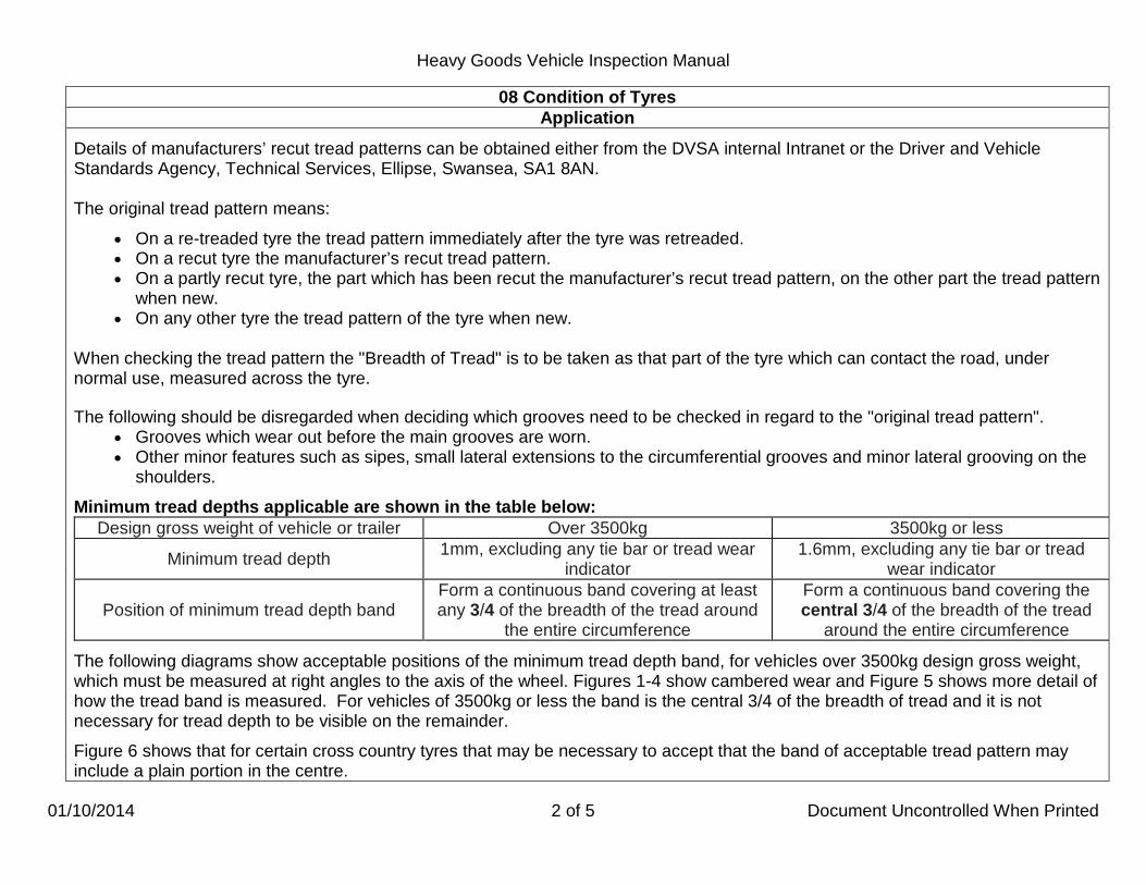
Heavy Goods Vehicle Inspection Manual
01/10/2014 2 of 5 Document Uncontrolled When Printed
08 Condition of Tyres Application
Details of manufacturers’ recut tread patterns can be obtained either from the DVSA internal Intranet or the Driver and Vehicle Standards Agency, Technical Services, Ellipse, Swansea, SA1 8AN. The original tread pattern means:
• On a re-treaded tyre the tread pattern immediately after the tyre was retreaded. • On a recut tyre the manufacturer’s recut tread pattern. • On a partly recut tyre, the part which has been recut the manufacturer’s recut tread pattern, on the other part the tread pattern
when new. • On any other tyre the tread pattern of the tyre when new.
When checking the tread pattern the "Breadth of Tread" is to be taken as that part of the tyre which can contact the road, under normal use, measured across the tyre. The following should be disregarded when deciding which grooves need to be checked in regard to the "original tread pattern".
• Grooves which wear out before the main grooves are worn. • Other minor features such as sipes, small lateral extensions to the circumferential grooves and minor lateral grooving on the
shoulders. Minimum tread depths applicable are shown in the table below:
Design gross weight of vehicle or trailer Over 3500kg 3500kg or less
Minimum tread depth 1mm, excluding any tie bar or tread wear indicator
1.6mm, excluding any tie bar or tread wear indicator
Position of minimum tread depth band Form a continuous band covering at least any 3/4 of the breadth of the tread around
the entire circumference
Form a continuous band covering the central 3/4 of the breadth of the tread
around the entire circumference The following diagrams show acceptable positions of the minimum tread depth band, for vehicles over 3500kg design gross weight, which must be measured at right angles to the axis of the wheel. Figures 1-4 show cambered wear and Figure 5 shows more detail of how the tread band is measured. For vehicles of 3500kg or less the band is the central 3/4 of the breadth of tread and it is not necessary for tread depth to be visible on the remainder. Figure 6 shows that for certain cross country tyres that may be necessary to accept that the band of acceptable tread pattern may include a plain portion in the centre.

Heavy Goods Vehicle Inspection Manual
01/01/2013 3 of 5 Document Uncontrolled When Printed
08 Condition of Tyres Application
Figures (1), (2), (3) and (4) T= Breadth of Tread ¾ T = Minimum width of continuous band. Fig 5
In this case the lateral grooves are the same depth as the circumferential groove and are included in the ¾ measurement. The breadth of the tread is ‘T’. The ¾ of ‘T’ measurement can be taken over ‘T’ as in figure 1 to 4.

Heavy Goods Vehicle Inspection Manual
01/01/2013 4 of 5 Document Uncontrolled When Printed
08 Condition of Tyres Application
Fig 6
This tyre only has lateral grooving The band of acceptable tread pattern includes the plain portion which existed when the tyre was new. The remaining tread area should contain grooves to the depth of 1 mm.

Heavy Goods Vehicle Inspection Manual
01/01/2013 5 of 5 Document Uncontrolled When Printed
08 Condition of Tyres Method of Inspection Reason for Failure
1. Check each tyre for:
a. cuts.
b. lumps, bulges or tears.
c. exposed ply or cords.
d. fouling on any part of the vehicle. e. correct seating on the wheel. f. wall contact with another tyre on a twin wheel. g. the base of any groove of the original tread pattern is
clearly visible.
h. the minimum tread depth and tread band requirement.
2. Check recut tyres: a. fitted to a vehicle are legally acceptable. b. to ensure the wholly or partly recut tread pattern is to the
manufacturer’s recut tread pattern.
1. A tyre
a. with a cut which is deep enough to reach the ply or cords, and is more than 25mm long, or 10% of the section width, whichever is greater.
**b. with a lump, bulge or tear caused by separation or partial
failure of its structure, including any lifting of the tread rubber.
*c. with exposed ply or cord.
d. fouling on any part of the vehicle. e. incorrectly seated on its wheel. f. on a twin wheel making wall contact with another tyre. g. where the base of any groove of the original tread pattern
is not clearly visible (vehicles with DGVW greater than 3500kg).
*h where the minimum tread depth and tread band
requirements are not met.
2. A recut tyre: a. fitted to a vehicle which should not have one. b. on which the wholly or partly recut tread pattern is not to
the manufacturer’s recut tread pattern.

Heavy Goods Vehicle Inspection Manual
01/01/2013 1 of 17 Document Uncontrolled When Printed
09 Sideguards, Rear Under-Run Devices & Bumper Bars Application
SIDEGUARDS Sideguards can be manufactured & tested to any of the following standards: The Road Vehicles (Construction and Use) Regulations 1986 as amended. Directive 89/297/EEC or The technical requirements of the Directive 89/297/EEC. Sideguards are applicable to: Motor Vehicles first used from 1 April 1984 with a design gross weight exceeding 3,500kg and where the distance between the centres of any two consecutive axles exceeds 3m; Trailers manufactured from 1 May 1983 with an unladen weight exceeding 1,020kg and where the distance between the centres of any two consecutive axles exceeds 3m; or in the case of a semi-trailer, where the distance between the centre of the kingpin position and the centre of the foremost axle exceeds 4.5m. Semi-Trailers manufactured before 1 May 1983 which have a design gross weight exceeding 26,000kg and which form part of an articulated vehicle with a design gross train weight exceeding 32,520kg and where the distance between the centre of the kingpin and the centre of the foremost axle exceeds 4.5m. Where more than one kingpin is fitted, it is the distance from the rearmost position which is taken into account. Exempted Vehicles:
• A vehicle or trailer constructed so that it can be unloaded by part of the vehicle being tipped sideways or rearwards. • A vehicle or trailer designed solely for use in connection with street cleaning, the collection/disposal of refuse or the contents of
gullies/cesspools. (Skip carrying vehicles are classed as refuse vehicles and as such are exempt). • A trailer specially designed and constructed, and not merely adapted, to carry round timber, beams or girders, being items of
exceptional length. • Tractor units. • A vehicle or trailer specially designed and constructed, and not merely adapted, to carry other vehicles loaded onto it from the front
or rear (Vehicles with a standard flat body fitted with a "beaver tail" are not exempt). • A trailer with a load platform which is not more than 750mm from the ground throughout that part of its length under which a
sideguard would have to be fitted. • A semi-trailer incorporating a sliding bogie.

Heavy Goods Vehicle Inspection Manual
01/01/2013 2 of 17 Document Uncontrolled When Printed
09 Sideguards, Rear Under-Run Devices & Bumper Bars Application
Exempted Vehicles (continued):
• A rigid motor vehicle or trailer designed for and constructed for the special purpose of carrying long (but not exceptionally long) timbers from an off road location in a forest.
To fulfil this definition the vehicle must meet the following criteria: a. It must be of skeletal construction. b. It must have a minimum of two upright side supports (sidebolsters) fitted to each side of the vehicle. c. It must not be fitted with a load platform, other than chassis rails, cross bearers and the minimum amount of flooring necessary
to protect wiring or brake line components. It is permissible for the vehicle to be fitted with the following:
Loading equipment i.e. a Hiab crane or similar device. Cross bearers that do not have upright side supports.
This list is not exhaustive but covers the vehicles likely to be encountered within the testing scheme. Vehicles equipped with cranes, it is not practicable to fit sideguards in the area of the crane and its controls. Before reaching a decision on its pass/fail criteria for vehicles/trailers you need to take account of the following; Vehicles fitted with an extendible device or leg to provide stability during loading, and equipped with loading devices and controls, which makes it impracticable to fully comply with the sideguard legislation, will be deemed compliant provided sideguards are in place to the fullest extent practicable. All vehicles must be presented for statutory test with any such devices in the stowed position. Vehicles with access and a working platform adjacent to, and necessary for, the operation of a loading device, shall be regarded as a load carrying platform for sideguard compliance forward of the extendable device or leg. Acceptable circumstances are when other items on the vehicle such as fuel tanks, work boxes etc which by virtue of their shape and characteristics conform to the requirements of a sideguard. Trailers manufactured before 1 May 1983 will not be failed if sideguards are not fitted, but the driver/operator notified that they may be required under certain circumstances.

Heavy Goods Vehicle Inspection Manual
01/01/2013 3 of 17 Document Uncontrolled When Printed
09 Sideguards, Rear Under-Run Devices & Bumper Bars Application
Sideguards fitted to vehicles/trailers that do not require them will only be checked for items (a), (c) and (g) in MoI 2. The continuous vertical rail or turn in may not be required if the front edge of the sideguard is within 100mm of a permanent structure of the vehicle (vehicle cab/wheel arch). REAR UNDER-RUN DEVICES Rear under-run devices are applicable for motor vehicles with a gross design weight exceeding 3,500kg and first used from 1 April 1984; or Trailers manufactured from 1 May 1983 with an unladen weight exceeding 1,020kg Exempted vehicles:
• Tractor units. • A vehicle or trailer fitted at the rear with apparatus specially designed for spreading material on a road. • A vehicle or trailer so constructed that it can be unloaded by part of the vehicle being tipped rearwards. • A vehicle or trailer specially designed and constructed, and not merely adapted, to carry other vehicles loaded onto it from the
rear. (Vehicles with a standard flat body fitted with a “beaver tail” are not exempt.) • A trailer specially designed and constructed, and not merely adapted, to carry round timber, beams or girders, being items of
exceptional length. • A vehicle or trailer fitted with a tail lift so constructed that a lift platform, with a minimum length of 1m, forms part of the floor of the
vehicle. • A vehicle specially designed, and not merely adapted, for the carriage and mixing of concrete.
This list is not exhaustive but covers the vehicles likely to be encountered within the testing scheme. If a vehicle has a rear tail lift, where the rear uprights for the tail lift are separated from the rear under-run, the uprights are not to be taken as part of the under-run device. Vehicles equipped with rear tail lifts are allowed to have gaps between the rear under-run rails. Gaps are permitted up to 500mm between rear under-run rails. Vehicles with tail lifts may be fitted with a guard up to 300mm wider than the outer edge of the outermost rear tyre provided it is no wider than the outer edge of the vehicle.

Heavy Goods Vehicle Inspection Manual
01/01/2013 4 of 17 Document Uncontrolled When Printed
09 Sideguards, Rear Under-Run Devices & Bumper Bars Application
Vehicles not required to be fitted with a rear under-run device but having one fitted are only to be inspected as if it was a bumper bar. Where a rear under- run extends outside the width of the outermost rear tyre but is joined to a sideguard positioned to the rear of the tyre, this is not a RfF. Vehicles that have two rear axles where the rearmost one has a narrower track, the sideguard criteria needs to comply with the widest of the rear axles. Vehicles with bodies that satisfy the dimensional requirements for rear under-run devices are considered acceptable. It is acceptable for a rigid vehicle to be presented for annual test without a rear under-run device fitted when towing a trailer. However, the under-run device must be readily available for use when not towing a trailer.
BUMPER BARS This inspection applies to all vehicles and trailers. Vehicles are not required to have separate bumper bars, these may be incorporated into the body in some cases. Further sideguard Information
Construction • The guard should be as continuous as possible and the outermost surface smooth, essentially rigid and either flat or horizontally
corrugated, but can be split into rails. Rails must be flat faced on the outside, (N2/O3 vehicles/trailers) minimum 50mm, (N3/O4 vehicle/trailers) minimum 100mm (but can be wider), and the distance between them not more than 300mm. Parts of the guard may be detachable for access, but must be securely fixed when the vehicle is in use.
• The front edge of the guard must have a continuous surface extending back for (N2/O3 vehicles/trailers) minimum 50mm;
(N3/O4 vehicle/trailers) minimum 100mm, for both ranges of vehicles the turning inwards is 100mm. • On occasions a single rail may fulfil this requirement and it will be sufficient that the forward face only covers the depth of the rail.
N2 N
vehicles are vehicles over 3500kg but does not exceed 12000kg DGVW. 3
O vehicles are vehicles that exceed 12000kg DGVW.
3 O
trailers are trailers over 3500kg but does not exceed 10,000kg TAW. 4 trailer are trailers which exceed 10,000kg TAW.
DGVW = Design Gross Vehicle Weight TAW = Total Axle Weight

Heavy Goods Vehicle Inspection Manual
01/01/2013 5 of 17 Document Uncontrolled When Printed
09 Sideguards, Rear Under-Run Devices & Bumper Bars Application
Distance of Guard from Front Wheels (or landing legs) and Rear Wheels
The front edge of the guard must not be more than 300mm from the tyre on the front wheel (or second wheel if two front axles) and the guard must extend to within 300mm of the tyre on the first rear axle.
Motor Vehicles
The front edge of the guard must not be more than 500mm from the tyre on the front wheel and the guard must extend to within 300mm of the tyre on the rear wheel.
Draw-Bar Trailer
The front edge of the guard can be up to 250mm behind the centre line of the landing legs, but never more than 3m behind the centre of the king pin (in its rearmost position) and the guard must extend to within 300mm of the tyre on the first rear axle.
Semi-Trailer
Backwards (N2/O3 vehicle/trailers) minimum 50mm (N3/O4 vehicle/trailers) minimum 100mm
Rail face (N2/O3 vehicle/trailers) minimum 50mm
Rail face (N3/O4 vehicle/trailers) minimum 100mm
Front edge
Inwards min 100mm

Heavy Goods Vehicle Inspection Manual
01/01/2013 6 of 17 Document Uncontrolled When Printed
09 Sideguards, Rear Under-Run Devices & Bumper Bars Application
Minimum Height to Top Edge To determine the height to the top edge, it is necessary to imagine a vertical plane parallel to the vehicle centre line and just touching the outer edge of the outermost rear tyre (neglecting the bulge). The line where the vertical plane cuts the structure of the vehicle is taken as the datum and may not be straight, but will move up and down as the plane cuts through transverse floor members etc. The upper edge of a sideguard shall not be more than 350mm below that part of the structure of the vehicle, cut or contacted by a vertical plane tangential to the outer surface of the tyres, excluding any bulging close to the ground except in the following cases.
Tangential plane should be taken as a line from the outermost edge of the rear tyre(s) excluding the bulge due to the weight of the vehicle.
More than 1.3m
Rear outermost tyre
Vertical plane
Vertical plane
Upper surface of load carrying structure
Rear outermost tyre
Body
Where the tangential plane cuts the structure of the vehicle at more than 1.3m above the ground, then the upper edge of the sideguard shall not be less than 950mm above the ground. Where the tangential plane does not cut the structure of the vehicle, the upper edge shall be level with the surface of the load carrying platform, or 950mm from the ground, whichever is the less.
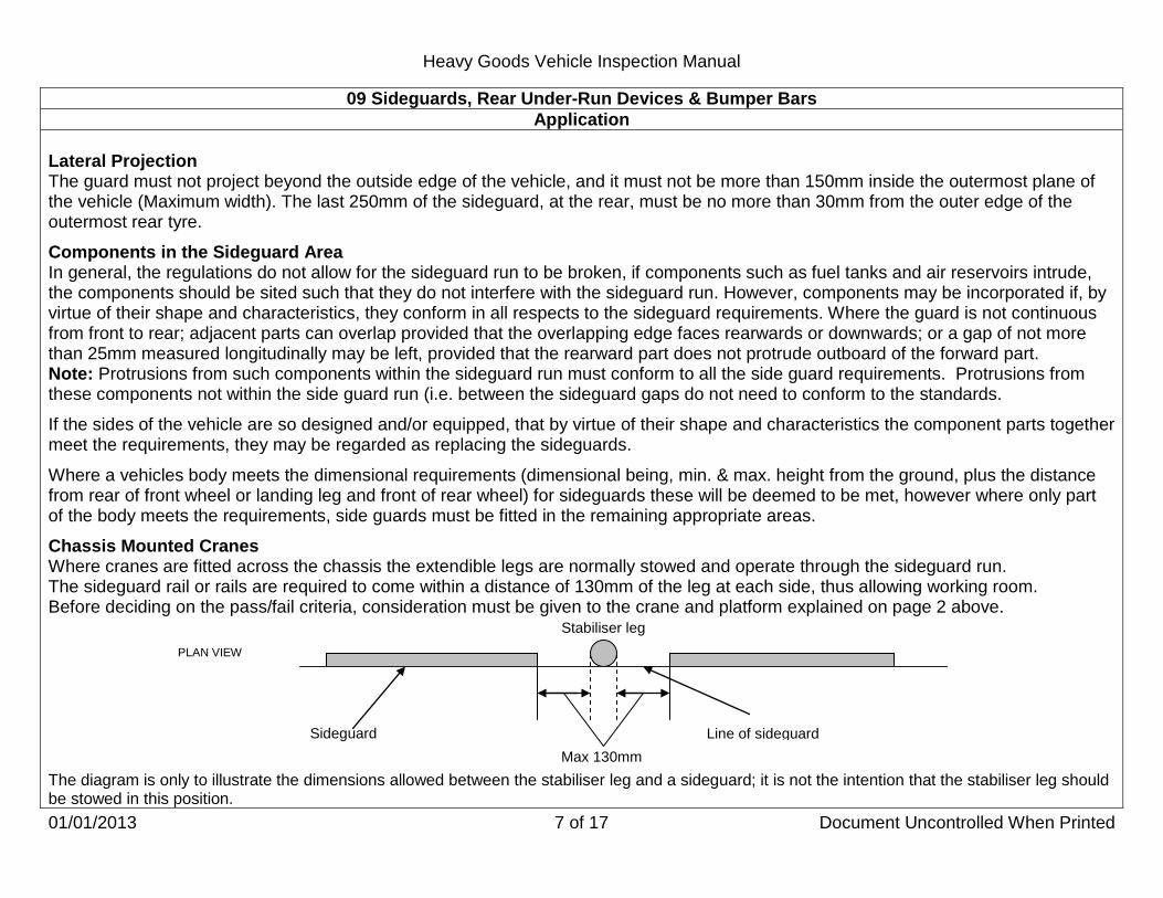
Heavy Goods Vehicle Inspection Manual
01/01/2013 7 of 17 Document Uncontrolled When Printed
09 Sideguards, Rear Under-Run Devices & Bumper Bars Application
Lateral Projection The guard must not project beyond the outside edge of the vehicle, and it must not be more than 150mm inside the outermost plane of the vehicle (Maximum width). The last 250mm of the sideguard, at the rear, must be no more than 30mm from the outer edge of the outermost rear tyre. Components in the Sideguard Area In general, the regulations do not allow for the sideguard run to be broken, if components such as fuel tanks and air reservoirs intrude, the components should be sited such that they do not interfere with the sideguard run. However, components may be incorporated if, by virtue of their shape and characteristics, they conform in all respects to the sideguard requirements. Where the guard is not continuous from front to rear; adjacent parts can overlap provided that the overlapping edge faces rearwards or downwards; or a gap of not more than 25mm measured longitudinally may be left, provided that the rearward part does not protrude outboard of the forward part. Note: Protrusions from such components within the sideguard run must conform to all the side guard requirements. Protrusions from these components not within the side guard run (i.e. between the sideguard gaps do not need to conform to the standards. If the sides of the vehicle are so designed and/or equipped, that by virtue of their shape and characteristics the component parts together meet the requirements, they may be regarded as replacing the sideguards. Where a vehicles body meets the dimensional requirements (dimensional being, min. & max. height from the ground, plus the distance from rear of front wheel or landing leg and front of rear wheel) for sideguards these will be deemed to be met, however where only part of the body meets the requirements, side guards must be fitted in the remaining appropriate areas. Chassis Mounted Cranes Where cranes are fitted across the chassis the extendible legs are normally stowed and operate through the sideguard run. The sideguard rail or rails are required to come within a distance of 130mm of the leg at each side, thus allowing working room. Before deciding on the pass/fail criteria, consideration must be given to the crane and platform explained on page 2 above. The diagram is only to illustrate the dimensions allowed between the stabiliser leg and a sideguard; it is not the intention that the stabiliser leg should be stowed in this position.
Stabiliser leg
Line of sideguard Sideguard Max 130mm
PLAN VIEW

Heavy Goods Vehicle Inspection Manual
01/01/2013 8 of 17 Document Uncontrolled When Printed
09 Sideguards, Rear Under-Run Devices & Bumper Bars Application
Sideguard Material There is no legislation regarding the materials used for sideguards although there are regulations covering strength and deflection of these components. None of these however are subject to test. Protrusions Protrusions (on the side guard outer faces) such as rivet or bolt heads are acceptable provided that they do not exceed 10mm and are suitably domed. External corners and edges must be rounded. Orange reflective strips are acceptable if fitted to sideguards provided that the front edge is rounded and it does not protrude more than 10mm. Short Bodied Vehicles Vehicles which have shortened bodies to facilitate the fitting of plant equipment usually have a large gap between the back of the cab and the body. There may therefore be a considerable length of sideguard area not covered by the body. In these cases the height of the guard covered by the body is the normal 350mm max below the structure, but the height of the guard in the area not covered by the body must be no lower than the body floor or 950mm whichever is the lowest and may require more than 1 rail. Type Approved Sideguards If the presenter claims that the vehicle or trailer is fitted with type approved sideguards (this will most often be on an imported trailer) which comply with the requirements of the EC directive, the presenter should be asked to provide documentary evidence. Although the standards are to accept sideguards made to the directive but not necessarily approved it may assist to identify those vehicles/trailers which are known to be approved, these are: Trailer Make Hellbender EUT, KIP, KIS, TSA, MUL, CONC.
Model
Magyar All models type approved. Vehicle Make Mercedes-Benz Atego.
Model

Heavy Goods Vehicle Inspection Manual
01/01/2013 9 of 17 Document Uncontrolled When Printed
09 Sideguards, Rear Under-Run Devices & Bumper Bars Application
Tankers It is recognised that there are practical problems in the fitting of sideguards to some tankers and there can be differing views over what constitutes "so far as is practicable".
A. Tankers which Convey Dangerous Substances
Vehicle Safety Division, the Society of Motor Manufacturers and Traders and the British Tank Manufacturers Technical Committee agreed on the design layout specification for sideguards on these vehicles. This agreement is summarised in the drawings that follow. In all other respects the guards must conform to the regulations.
B. Skeletal Trailers Carrying Frameless Tanks
(i.e. a tank or container which does not have a lower side rail or rave).
Sideguards fitted to skeletal trailers carrying frameless tanks must incorporate a top rail, the upper edge of which should be at least 950mm from the ground or to the height of the trailers upper tank carrying surface (e.g. twist locks) if this is less than 950mm.
C. Milk Tankers with External Cylindrical Tubes for Stowage of Hoses
An external cylindrical tube permanently fitted longitudinally to the side of a vehicle and intended for the stowage of a hose, can for the purpose of the sideguard positional requirements be considered part of the body. This only applies to that side of the vehicle fitted with the cylindrical tube and where the tube completely extends over the length of the vehicle required to be fitted with sideguards. Any other type of hose support, e.g. rack or tray, should not be considered part of the bodywork.
D. Hose Racks
With the exception stated at "C" above, a hose rack fitted to a vehicle or trailer should be disregarded when making an assessment as to whether the body cuts the vertical plane as in the section dealing with Maximum Height to Top Edge. It is however permissible for the hose rack to be taken as part of the sideguard if it meets the dimensional requirements.

Heavy Goods Vehicle Inspection Manual
01/01/2013 10 of 17 Document Uncontrolled When Printed
09 Sideguards, Rear Under-Run Devices & Bumper Bars Application
At least 950mm
Sideguards must be no more than 150mm in from the outermost plane of the vehicle (maximum width). The last 250mm of the guard at the rear must be no more than 30mm from the tangential plane of the rear tyres.

Heavy Goods Vehicle Inspection Manual
01/01/2013 11 of 17 Document Uncontrolled When Printed
09 Sideguards, Rear Under-Run Devices & Bumper Bars Application
At least 950mm
At least 950mm
Sideguards must be no more than 150mm in from the outermost plane of the vehicle (maximum width). The last 250mm of the guard at the rear must be no more than 30mm from the tangential plane of the rear tyres.

Heavy Goods Vehicle Inspection Manual
01/01/2013 12 of 17 Document Uncontrolled When Printed
09 Sideguards, Rear Under-Run Devices & Bumper Bars Application
At least 950mm
Ladders encroaching into the sideguard area must comply with the side guard regulations (not applicable to fluid tankers)
Sideguards must be no more than 150mm in from the outermost plane of the vehicle (maximum width). The last 250mm of the guard at the rear must be no more than 30mm from the tangential plane of the rear tyres.
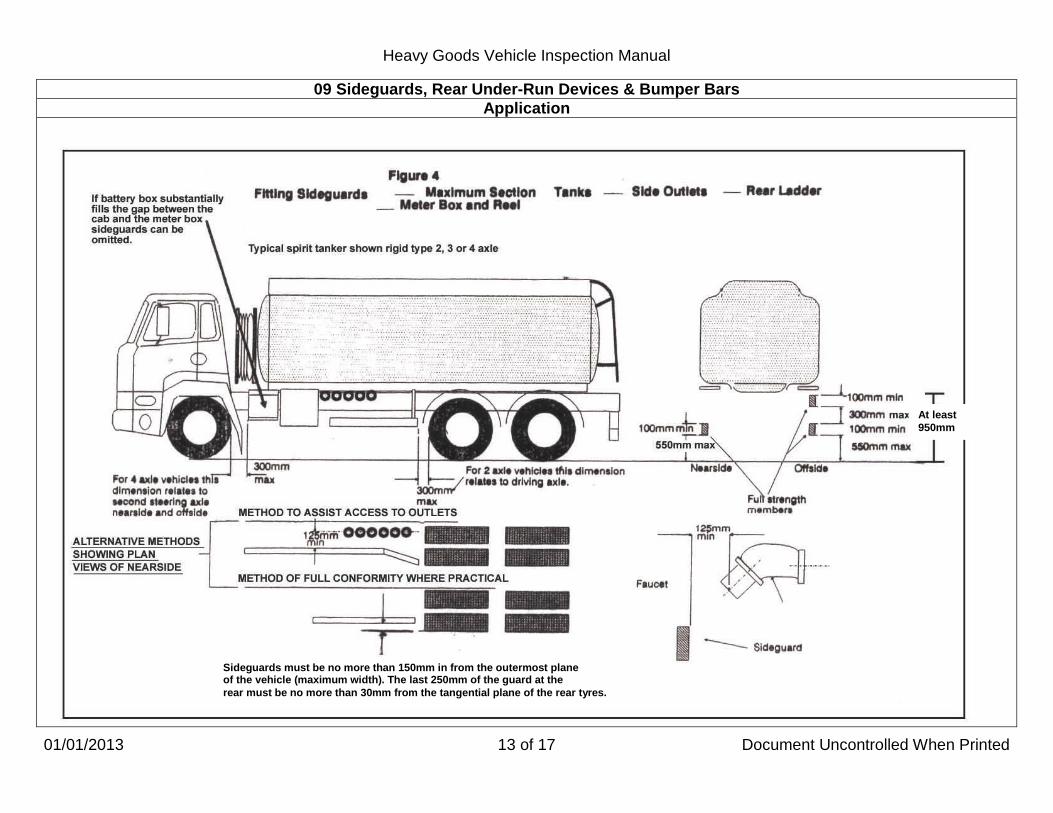
Heavy Goods Vehicle Inspection Manual
01/01/2013 13 of 17 Document Uncontrolled When Printed
09 Sideguards, Rear Under-Run Devices & Bumper Bars Application
At least 950mm
Sideguards must be no more than 150mm in from the outermost plane of the vehicle (maximum width). The last 250mm of the guard at the rear must be no more than 30mm from the tangential plane of the rear tyres.

Heavy Goods Vehicle Inspection Manual
01/01/2013 14 of 17 Document Uncontrolled When Printed
09 Sideguards, Rear Under-Run Devices & Bumper Bars Application
At least 950mm
A=
Sideguards must be no more than 150mm in from the outermost plane of the vehicle (maximum width). The last 250mm of the guard at the rear must be no more than 30mm from the tangential plane of the rear tyres.

Heavy Goods Vehicle Inspection Manual
01/01/2013 15 of 17 Document Uncontrolled When Printed
09 Sideguards, Rear Under-Run Devices & Bumper Bars Application
At least 950mm
Sideguards must be no more than 150mm in from the outermost plane of the vehicle (maximum width). The last 250mm of the guard at the rear must be no more than 30mm from the tangential plane of the rear tyres.

Heavy Goods Vehicle Inspection Manual
01/01/2013 16 of 17 Document Uncontrolled When Printed
09 Sideguards, Rear Under-Run Devices & Bumper Bars Method of Inspection Reason for Failure
Check Sideguards for: 1. fitment to a vehicle required to have them. 2. Check a sideguard or bracket for:
a. security. b. condition.
c. surfaces which are smooth.
d. external edges that are radiused. e. correct dimensions visually. f. being continuous along the vehicle length in other than
accepted circumstances (See application) . g. overall width. h. the height from the ground to the lowest edge of the guard.
(Not applicable to semi trailers attached to a tractor unit where the lower edge is not horizontal with the ground, there is no requirement to separate the trailer from the tractor).
Sideguards: 1. not fitted to a vehicle required to have them fitted. 2. A sideguard or bracket:
a. insecure. b. cracked, fractured, corroded or damaged so that its
effectiveness is reduced.
c. with exposed surfaces which are not smooth (e.g. projecting brackets, jagged edges, bolt heads that are not dome shaped).
d. with external edges that are not radiused. e. with incorrect dimensions. f. that is not continuous along the vehicle length in other than
accepted circumstances. g. that increases the overall width of the vehicle. h. with more than 550mm height from the ground to the lowest
edge of the guard. (vehicle unladen or semi-trailer load platform horizontal).

Heavy Goods Vehicle Inspection Manual
01/01/2013 17 of 17 Document Uncontrolled When Printed
09 Sideguards, Rear Under-Run Devices & Bumper Bars Method of Inspection Reason for Failure
Check Rear Under-Run Devices are: 3. fitted to a vehicle required to have one. 4. Check a Rear Under-Run device for:
a. security. b. condition. c. jagged edges.
d. being no more than 550mm from the ground unladen. e. not extending beyond the outer edge of the outermost rear
tyre. f. the outer end of the device being no more than 100mm
inboard of the outer edge of the outermost rear tyre (or not more than 300mm inboard where a demountable body is fitted).
g. not extending beyond the outermost width of the vehicle
which is fitted with a tail lift.
h. complete. 5. Check a bumper bar or bracket for:
a. security.
b. jagged or projecting edges.
Rear Under-Run Device: 3. not fitted to a vehicle required to have one fitted. 4. A Rear Under-Run device:
a. insecure. b. cracked, fractured, corroded or damaged so that its
effectiveness is reduced.
c. that has a jagged edge. d. with more than 550mm ground clearance (unladen). e. which extends beyond the outer edge of the outermost rear
tyre (see note in application). f. with the outer end of the device more than 100mm inboard
of the outer edge of the outermost rear tyre (or more than 300mm inboard where a demountable body is fitted).
g. extends beyond the outermost width of the vehicle which is
fitted with a tail lift.
h. incomplete. 5. A bumper bar or bracket which is:
a. insecure. b. has a jagged or projecting edge likely to cause injury.

Heavy Goods Vehicle Inspection Manual
01/01/2013 1 of 1 Document Uncontrolled When Printed
10 Spare Wheel & Carrier Application
This inspection applies to all vehicles and trailers fitted with a spare wheel or carrier.
Method of Inspection Reason for Failure
1. Check the spare wheel and carrier are secure, free from
damage, and are correctly positioned.
1.
A spare wheel or carrier so insecure, damaged or positioned so that either is likely to fall from the vehicle.

Heavy Goods Vehicle Inspection Manual
01/01/2013 1 of 2 Document Uncontrolled When Printed
11 Vehicle to Trailer Coupling Application
This examination applies to all vehicles fitted with a trailer coupling (at the front or at the rear) and to all trailers. This inspection also covers fifth wheel couplings mounted on converter dollies. If the vehicle has a coupled trailer it must not be uncoupled. To check for relative movement between the tractor and trailer apply the trailer brakes and ask the driver to lightly shunt the tractor back and forth. When assessing wear/lift between bracket/bush or pin/bush consideration should be given to those bushes which have been designed to provide a cushioning effect in order to relieve shock loadings. The load when the bush is fully compressed is taken from the main plate directly onto the mounting bracket and therefore some degree of controlled lift, up to 8mm in some units is acceptable in the trunnion pin and bush (Up to 12mm lateral movement is acceptable in some cases in fifth wheel couplings, lateral movement of draw-bar turntable top plate movement relative to the lower plate should not exceed 10mm). Wear should be considered excessive if a drawing hitch, bar, hook, eye, ball or ball socket has the metal reduced to ¾ of its original thickness. If the inspection of the fifth wheel jaws is carried out without a trailer attached, then wear on the jaws in excess of 6mm would be considered a Reason for Failure. Many manufacturers determine gross train weights by the number and size of bolts fitted to fifth wheel bed plates and sub-frames, these bolts are therefore considered to be mandatory. Examples of a secondary locking devices are:
a. A dog clip and chain. b. Spring loaded pin between the operating handle and the body of the 5th
c. Lever dropped behind the operating handle. wheel housing.
An optional third 5th wheel locking device such as a dog clip with a chain or wire from the secondary clip to a hole in the handle could be fitted. The chain or wire may only be there to assist the operator to unlock the secondary device. The absence of a chain/wire is not a RfF if its only purpose is to prevent loss of the dog clip.

Heavy Goods Vehicle Inspection Manual
01/01/2013 2 of 2 Document Uncontrolled When Printed
11 Vehicle to Trailer Coupling Method of Inspection Reason for Failure
1. Check the drawing hitch, bar, hook, eye, ball or ball, socket; or
a fifth wheel king pin and its mounting or a turntable for:
a. wear. b. distortion.
c. cracking. d. security. e. movement. f. clearance between upper and lower plates of a turntable.
g. presence and operation of locking device.
2. Check the Fifth Wheel Coupling for: a. security between the fifth wheel and its mounting sub-
frame and or chassis. b. all mandatory bolts are secure and present. c. wear and adjustment of the jaws. d. the safety locking device being operative. e. wear in an articulating bracket or pivot and its security. f. cracks in a load bearing member. g. security and wear of any operating members to the extent
the coupling is safe.
1. A drawing hitch, bar, hook, eye, ball or ball socket; or a fifth
wheel king pin and its mounting or a turntable which: a. is excessively worn. b. is seriously deformed impairing its effectiveness and or
weakens the component. *c. is cracked.
d. is insecure. *e. has excessive movement between the vehicle and trailer.
f. a turntable which has no clearance between mating surfaces, i.e. evidence of contact between the surfaces.
g. has a missing, damaged, seized and or inadequate safety or locking device.
2. A Fifth Wheel Coupling with: a. insecurity between the fifth wheel and its mounting sub-
frame and or chassis. b. a mandatory bolt loose or missing. c. jaws so worn or out of adjustment that the trailer kingpin
might not be securely held. d. a safety locking device is inoperative. e. an articulating bracket or pivot excessively worn or
insecure. f. any crack in a load bearing member. g. an operating member insecure or worn to such an extent
the coupling is unsafe.

Heavy Goods Vehicle Inspection Manual
01/01/2013 1 of 2 Document Uncontrolled When Printed
12 Trailer Parking and Emergency Brakes and Air Line Connections Application
Parking and Emergency Brakes This inspection applies to all trailers. Air Line Connections This inspection applies to all trailers of whatever age and to drawing vehicles first used from 1 April 1989.
Emergency Brake and Air Line Connections:
• Ensure that the air reservoirs on the drawing vehicle are fully charged. • With the vehicle parking brake on and the trailer parking brake off, ask the driver to disconnect the service (yellow) and
emergency (red) brake lines. • Check, on vehicles and trailers fitted with "C" type couplings, that the coupling in the service (yellow) line - either fitted to the
trailer or in the line itself - is fitted with an operating adaptor which can open the self sealing coupling in the connector from the drawing vehicle.
• Check that the operating adaptor lifts the indicator on the test coupling by the correct amount. The waisted portion (coloured section) of the indicator must be exposed, but no more than this. This does not include additional couplings which may be used on trailers such as extendable types.
• Check that any brake line on the drawing vehicle is not fitted with a manual shut-off tap. Additional taps fitted to extendable trailers are not included in this inspection.
The driver must be instructed to reconnect all couplings before the vehicle is moved When presented, the tractor unit must be compatible with the trailer and have a warning lamp to indicate that trailer ABS is working (This may be a combined ABS/EBS warning light). If presented with a compatible EBS tractor unit, if the red line is dropped, the brakes may not come on. To apply the brakes disconnect the ISO 7638 electrical connection. Ensure that the handbrake is applied on the tractor unit before disconnecting the red line and that safe working practices are followed. Provided self sealing couplings are used on the tractor couplings it does not matter whether the air adaptor couplings are the conventional way or reversed. Some park brake controls also deplete the air suspension systems when the red air line is removed, this is acceptable provided it does not drain the air brake reservoir. If it does the vehicle must fail under RfF 5a of section 59.
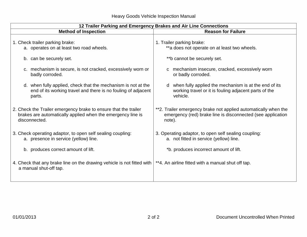
Heavy Goods Vehicle Inspection Manual
01/01/2013 2 of 2 Document Uncontrolled When Printed
12 Trailer Parking and Emergency Brakes and Air Line Connections Method of Inspection Reason for Failure
1. Check trailer parking brake:
a. operates on at least two road wheels. b. can be securely set.
c. mechanism is secure, is not cracked, excessively worn or
badly corroded.
d. when fully applied, check that the mechanism is not at the end of its working travel and there is no fouling of adjacent parts.
2. Check the Trailer emergency brake to ensure that the trailer brakes are automatically applied when the emergency line is disconnected.
3. Check operating adaptor, to open self sealing coupling: a. presence in service (yellow) line. b. produces correct amount of lift.
4. Check that any brake line on the drawing vehicle is not fitted with a manual shut-off tap.
1. Trailer parking brake: **a does not operate on at least two wheels.
**b cannot be securely set. c mechanism insecure, cracked, excessively worn or badly corroded. d when fully applied the mechanism is at the end of its working travel or it is fouling adjacent parts of the
vehicle.
**2. Trailer emergency brake not applied automatically when the emergency (red) brake line is disconnected (see application note).
3. Operating adaptor, to open self sealing coupling: a. not fitted in service (yellow) line. *b. produces incorrect amount of lift.
**4. An airline fitted with a manual shut off tap.

Heavy Goods Vehicle Inspection Manual
01/01/2013 1 of 1 Document Uncontrolled When Printed
13 Trailer Landing Legs
Application This inspection applies to all trailers fitted with landing legs. If any leg or part of a leg is missing it is not a Reason for Failure.
Method of Inspection Reason for Failure
1. Check for security of the landing leg and any component part.
1. A landing leg or any component part so insecure that it is
likely to fall from the vehicle.
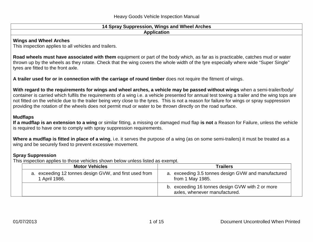
Heavy Goods Vehicle Inspection Manual
01/07/2013 1 of 15 Document Uncontrolled When Printed
14 Spray Suppression, Wings and Wheel Arches Application
Wings and Wheel Arches This inspection applies to all vehicles and trailers. Road wheels must have associated with them equipment or part of the body which, as far as is practicable, catches mud or water thrown up by the wheels as they rotate. Check that the wing covers the whole width of the tyre especially where wide “Super Single” tyres are fitted to the front axle. A trailer used for or in connection with the carriage of round timber does not require the fitment of wings. With regard to the requirements for wings and wheel arches, a vehicle may be passed without wings when a semi-trailer/body/ container is carried which fulfils the requirements of a wing i.e. a vehicle presented for annual test towing a trailer and the wing tops are not fitted on the vehicle due to the trailer being very close to the tyres. This is not a reason for failure for wings or spray suppression providing the rotation of the wheels does not permit mud or water to be thrown directly on the road surface. Mudflaps If a mudflap is an extension to a wing or similar fitting, a missing or damaged mud flap is not a Reason for Failure, unless the vehicle is required to have one to comply with spray suppression requirements. Where a mudflap is fitted in place of a wing, i.e. it serves the purpose of a wing (as on some semi-trailers) it must be treated as a wing and be securely fixed to prevent excessive movement. Spray Suppression This inspection applies to those vehicles shown below unless listed as exempt.
Motor Vehicles Trailers a. exceeding 12 tonnes design GVW, and first used from
1 April 1986. a. exceeding 3.5 tonnes design GVW and manufactured
from 1 May 1985. b. exceeding 16 tonnes design GVW with 2 or more
axles, whenever manufactured.

Heavy Goods Vehicle Inspection Manual
01/01/2013 2 of 15 Document Uncontrolled When Printed
14 Spray Suppression, Wings and Wheel Arches Application
Spray Suppression Exempted Vehicles:
• Motor vehicle where the driving power of its engine is, or can by use of its controls be, transmitted to all the wheels on at least one front axle and on at least one rear axle.
• Vehicles with a high ground clearance (400mm minimum). • A vehicle specially designed and not merely adapted for the carriage and mixing of concrete. • A vehicle or trailer constructed so that it can be unloaded by part of the vehicle being tipped sideways or rearwards. • A vehicle or trailer designed solely for use in connection with street cleaning, the collection/disposal of refuse or the contents of
gullies/cesspools (skip carrying vehicles are classed as refuse vehicles and as such are exempt). • A trailer specially designed and constructed, not merely adapted, to carry round timber, beams or girders being items of
exceptional length. • A rigid motor vehicle or trailer designed for and constructed for the special purpose of carrying long (but not exceptionally
long) timbers from an off road location in a forest. To fulfil this definition the vehicle must meet the following criteria:
a. It must be of skeletal construction. b. It must have a minimum of two upright side supports (sidebolsters) fitted to each side of the vehicle. c. It must not be fitted with a load platform, other than chassis rails, cross bearers and the minimum amount of flooring
necessary to protect wiring or brake line components.
It is permissible for the vehicle to be fitted with the following: Loading equipment e.g. a Hiab crane or similar device. Cross bearers that do not have upright side supports.
This list is not exhaustive but covers the vehicles likely to be encountered within the testing scheme. Tractor units drawing exempt trailers are not themselves exempt.
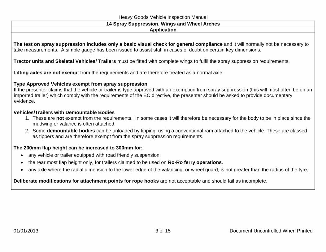
Heavy Goods Vehicle Inspection Manual
01/01/2013 3 of 15 Document Uncontrolled When Printed
14 Spray Suppression, Wings and Wheel Arches Application
The test on spray suppression includes only a basic visual check for general compliance and it will normally not be necessary to take measurements. A simple gauge has been issued to assist staff in cases of doubt on certain key dimensions. Tractor units and Skeletal Vehicles/ Trailers must be fitted with complete wings to fulfil the spray suppression requirements. Lifting axles are not exempt from the requirements and are therefore treated as a normal axle.
Type Approved Vehicles exempt from spray suppression If the presenter claims that the vehicle or trailer is type approved with an exemption from spray suppression (this will most often be on an imported trailer) which comply with the requirements of the EC directive, the presenter should be asked to provide documentary evidence. Vehicles/Trailers with Demountable Bodies
1. These are not exempt from the requirements. In some cases it will therefore be necessary for the body to be in place since the mudwing or valance is often attached.
2. Some demountable bodies can be unloaded by tipping, using a conventional ram attached to the vehicle. These are classed as tippers and are therefore exempt from the spray suppression requirements.
The 200mm flap height can be increased to 300mm for:
• any vehicle or trailer equipped with road friendly suspension. • the rear most flap height only, for trailers claimed to be used on Ro-Ro ferry operations. • any axle where the radial dimension to the lower edge of the valancing, or wheel guard, is not greater than the radius of the tyre.
Deliberate modifications for attachment points for rope hooks are not acceptable and should fail as incomplete.

Heavy Goods Vehicle Inspection Manual
01/01/2013 4 of 15 Document Uncontrolled When Printed
14 Spray Suppression, Wings and Wheel Arches Application
The width of the flap should cover the full breadth of the tyre(s). Vehicles/trailers first used from 1 April 2000 must have spray suppression that covers the whole width of the tyres. It is acceptable for vehicles/trailers before 1 April 2000 that the spray suppression will only cover the tyre tread breadth. Earlier Mercedes Actros model ranges had gaps between the spray suppression flap top edge and the mud wing bottom edge (the edges were not parallel with each other); these do not comply with the spray suppression requirements and should be failed. The later models do comply because the gap is at the same level as the mud wing thus containing the spray thrown up by the rotation of the wheel (see below).
On trailers where all the wheels steer, it may appear to be incompatible to fit spray suppression, these vehicles are not exempt but spray suppression only needs fitting as far as it is practicable.

Heavy Goods Vehicle Inspection Manual
01/01/2013 5 of 15 Document Uncontrolled When Printed
14 Spray Suppression, Wings and Wheel Arches Application
Conventional Mudwing Types of Wheel Guards Single Axle Arrangements or Multi-axle arrangements where distance between wheels is greater than 300mm. The lower edge of the outer valance shall not exceed 1.5 x tyre radius on steerable wheels or 1.25 x tyre radius on non-steerable wheels at points A, B and C.

Heavy Goods Vehicle Inspection Manual
01/01/2013 6 of 15 Document Uncontrolled When Printed
14 Spray Suppression, Wings and Wheel Arches Application
Wheel Flaps Wheel flaps must be fitted behind each wheel and should cover the full breadth of the tyre(s) and be mounted to the wing without gaps that would permit the exit of spray. Suppression material must be fitted to:
a. the forward face of the flap and b. to the forward face of that part of the wing (guard) if it reaches below a line 100mm above a line projected from the wheel centre
line. Wheel Guards Where the wheel guard consists of several components there should be no gaps between or within individual parts when assembled that will permit the exit of spray when the vehicle is in motion.
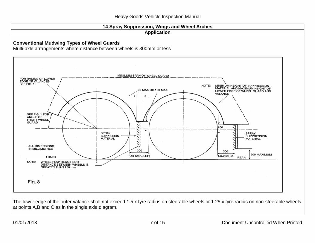
Heavy Goods Vehicle Inspection Manual
01/01/2013 7 of 15 Document Uncontrolled When Printed
14 Spray Suppression, Wings and Wheel Arches Application
Conventional Mudwing Types of Wheel Guards Multi-axle arrangements where distance between wheels is 300mm or less
The lower edge of the outer valance shall not exceed 1.5 x tyre radius on steerable wheels or 1.25 x tyre radius on non-steerable wheels at points A,B and C as in the single axle diagram.

Heavy Goods Vehicle Inspection Manual
01/01/2013 8 of 15 Document Uncontrolled When Printed
14 Spray Suppression, Wings and Wheel Arches Application
Wheel Flaps Wheel flaps should cover the full breadth of the tyre(s) and be mounted to the wing without gaps that would permit the exit of spray. Wheel flaps are required behind each wheel where the distance between tyres on a group of multiple axles is 250mm or more. Up to 290mm can be accepted where it is clear that the limit of 249mm is exceeded only by tyre wear. Where the distance between tyres on a group of axles is less than 250mm, wheel flaps are only required on the rearmost axle of each group. Suppression material must be fitted to:
• The forward face of the flap and
• The forward face of that part of the wing (guard) if it reaches below a line 100mm above a line projected from the wheel centre line.
Wheel Guards Where the wheel guard consists of several components there should be no gaps between or within individual parts when assembled that will permit the exit of spray when the vehicle is in motion.

Heavy Goods Vehicle Inspection Manual
01/01/2013 9 of 15 Document Uncontrolled When Printed
14 Spray Suppression, Wings and Wheel Arches Application
Single or Multi-axle arrangements using Half Wing and Valances.
The lower edge of the outer valance shall not exceed 1.5 x tyre radius on steerable wheels or 1.25 x tyre radius on non-steerable wheels at points A, B and C.
FRONT
20° ‘A’
‘B’
‘C’
VALENCE 45mm MIN.
200mm MAX.
VALENCE 45mm MIN.
Fig.4
300mm MAX.
100mm MIN.

Heavy Goods Vehicle Inspection Manual
01/01/2013 10 of 15 Document Uncontrolled When Printed
14 Spray Suppression, Wings and Wheel Arches Application
Wheel Flaps Wheel flaps must be fitted behind each wheel and should cover the full breadth of the tyre(s) and be mounted to the wing without gaps that would permit the exit of spray. Where the distance between tyres on a group of axles is less than 250mm, wheel flaps are only required on the rearmost axle of each group. Up to 290mm can be accepted if it is clear that the limit of 249mm is exceeded only by tyre wear. Suppression material must be fitted to:
• The forward face of the flap and
• to the forward face of that part of the wing (guard) if it reaches below a line 100mm above a line projected from the wheel centre line.
Wheel Guards Where the wheel guard consists of several components there should be no gaps between or within individual parts when assembled that will permit the exit of spray when the vehicle is in motion. Note that in the case of steerable wheels the 20 Deg. angle is increased to 30 Deg. The breadth of the wing valance at points A and C must be at least 45mm as must be the body valance depth at point B.

Heavy Goods Vehicle Inspection Manual
01/10/2014 11 of 15 Document Uncontrolled When Printed
14 Spray Suppression, Wings and Wheel Arches Application
Flap and Valance System for Non-Steered Axles
The valance should cover the area extending from the underside of the body to at least a line formed by the tangent to the top of the tyres and between the outer edge of the wheel flap, with which it should form a seal and the vertical plane formed by the tangent at the front of the tyre. An outer valance must be fitted over each wheel. The whole inner face of the outer valance, the depth of which should not be less than 100mm, must be fitted with a suppression material.

Heavy Goods Vehicle Inspection Manual
01/01/2013 12 of 15 Document Uncontrolled When Printed
14 Spray Suppression, Wings and Wheel Arches Application
Wheel Flaps
Wheel flaps should extend to the underside of the vehicle structure. The whole of the forward facing part of the wheel flap should be fitted with a suppression material or device. There should be no gaps that would permit the exit of spray. Suppression material must be fitted to
• the forward face of the flap and
• to the forward face of that part of the wing (guard) if it reaches below a line 100mm above a line projected from the wheel centre line.

Heavy Goods Vehicle Inspection Manual
01/01/2013 13 of 15 Document Uncontrolled When Printed
14 Spray Suppression, Wings and Wheel Arches Application
Spray Suppression Systems with Air/Water Separation Devices on the Lower Edge of Valances ("Cats Whiskers" or "Netlon") Single axle and Multi-axle arrangements.
The Wheel Guards should comply in all respects with the requirements given for the conventional mudwing system. Valances should have air/water separating material on their lower edges to a depth of not less than 45mm to the rear of the vertical centre line of the wheel. This depth may be progressively reduced forward of the centre line. There should be no openings in outer valances or between outer valances or wheel guards that would allow spray to be emitted. For non-steered wheels, the radius of the lower edge of the valance, including the air/water separating device, must not be greater than the radius of the tyre. With steered wheels however the radius of the lower edge can be up to approximately 25mm larger than the radius of the tyre.

Heavy Goods Vehicle Inspection Manual
01/01/2013 14 of 15 Document Uncontrolled When Printed
14 Spray Suppression, Wings and Wheel Arches Application
Wheel flaps must be either Fitted with suppression material to:
• the forward face of the flap and
• to the forward face of that part of the wing (guard) if it reaches below a line 100mm above a line projected from the wheel centre line (as at "A" in the diagram above).
or
• the lower part should consist of an air/water separator, the length of which shall be at least 100mm. The maximum height of the bottom edge should not exceed 200mm and the maximum distance behind the tyre is reduced to 200mm (as at "B" in the diagram above).
Where the distance between tyres on a group of axles is less than 250mm, wheel flaps are only required on the rearmost axle of each group. Up to 290mm can be accepted if it is clear that the limit of 249mm is exceeded only by tyre wear.

Heavy Goods Vehicle Inspection Manual
01/01/2013 15 of 15 Document Uncontrolled When Printed
14 Spray Suppression, Wings and Wheel Arches Method of Inspection Reason for Failure
Wings and Wheel Arches. 1. Check all Wings or Wheel Arches for:
a. presence and security or, in the case of a mud flap fitted as a wing, it is restrained or constructed to stop wind lift.
b. corrosion and distortion.
c. sharp edges that are likely to cause injury.
d. rubbing on a tyre.
e. covering the whole width of a tyre when the wheel is in the straight ahead position.
Spray Suppression. 2. Check Spray Suppression for:
a. presence where required. b. completeness and free from serious defects.
c. dimensions complying with requirements.
d. wheel flap(s) being restrained or stiff enough to stop
excessive movement or wind lift in normal use.
e. being clogged with mud or debris.
Wings and Wheel Arches. 1. A Wing or Wheel Arch:
a. missing or so insecure that it can fall off or rub on the tyre, or, in the case of a mud flap fitted as a wing, it is not restrained or constructed to stop wind lift.
b. so badly corroded or distorted to stop it acting as an
adequate shield.
c. that has sharp edges that are likely to cause injury. d. which is rubbing on a tyre.
e. which does not cover the whole width of a tyre when the
wheel is in the straight ahead position. Spray Suppression. 2. Spray Suppression:
a. insecure or not fitted where required. b. incomplete or seriously defective.
c. dimensions do not comply with requirements.
d. with a wheel flap not restrained or stiff enough to stop
excessive movement or wind lift in normal use.
e. with more than 25% of the minimum required wheel flap or spray suppression material area clogged with mud or debris.

Heavy Goods Vehicle Inspection Manual
01/01/2013 1 of 1 Document Uncontrolled When Printed
15 Cab Security Application
This inspection applies to all vehicles. All means of securing the cab are to be inspected where practical. Movement which is designed into mountings should not be confused with excessive wear. Cab security inspection applies to the primary and secondary locking devices for tilt cabs. The inspection does not cover air leaks from cab air suspension unless it affects the brakes. This would be an RfF within the appropriate brake section.
Method of Inspection Reason for Failure
1.
a. Check for security and condition by pushing and rocking the cab by hand where practical.
b. On tilt cabs examine the retention and/or locking devices
for damage and security.
c. Check the front hinge pins and/or brackets for wear such that safe control of the vehicle is not affected.
d. Check there is no excessive corrosion or damage to a
load bearing member which seriously reduces its strength near the cab mountings.
e. Visually check wind deflectors and other cab mounted
accessories for security.
1.
** a. Any insecurity that is likely to affect the drivers control of the vehicle.
b. A retention and/or locking device on a tilt cab missing or
defective. c. Wear of front hinge pins and/or brackets such that safe
control of the vehicle may be impaired.
d. Excessive corrosion or damage to a load bearing member which seriously reduces its strength near the cab mountings.
e. A wind deflector or other accessory so obviously insecure
that it is likely to become detached.

Heavy Goods Vehicle Inspection Manual
01/01/2013 1 of 1 Document Uncontrolled When Printed
16 Cab Doors Application
This application applies to all vehicles Only one operational door is required. On security vehicles this door may be fitted so that it does not open directly into the cab. Other doors which have deliberately been made inoperative should be considered part of the cab and not a door. A door with one handle missing should not be failed, if the door can be opened from inside using the remaining handle.
Method of Inspection Reason for Failure
1. Check that a door:
a. is fitted. b. can be opened.
c. is not so worn or damaged that the door is very difficult to
open or close.
d. opens and closes and check that they will not open inadvertently.
1. A Door which:
a. is missing. b. cannot be opened.
c. is worn or damaged so that it is very difficult to open or
close.
d. will not remain closed or is likely to fly open inadvertently (If a door fitted with a two position catch will only engage in the first or semi-shut position, this will be regarded as a reason for failure).

Heavy Goods Vehicle Inspection Manual
01/01/2013 1 of 1 Document Uncontrolled When Printed
17 Cab Floor and Steps
Application This inspection applies to all vehicles.
Method of Inspection Reason for Failure
1. Examine the condition of the cab floor and internal wheel arches.
2. Examine the condition and security of the steps to cab.
1. A cab floor or internal wheel arch which is so badly deteriorated or insecure that it would impair the drivers control.
2. Any step or step ring so insecure or dangerous that it is likely to cause injury.

Heavy Goods Vehicle Inspection Manual
20/03/2013 1 of 1 Document Uncontrolled When Printed
18 Seats Application
This inspection applies to all vehicles. When checking the driver’s seat adjustment it is not necessary to check that the seat can be secured in all possible positions. In the case of electrically adjusted seats, it is not necessary to check any ‘memory position’ function.
Method of Inspection Reason for Failure
1. Check the driver’s seat for condition and security.
2. Check that the driver’s seat position can be adjusted forwards and backwards and secured in the selected positions.
3. Check all passenger seats for security and that the back rest
can be secured in the upright position.
*1. A driver’s seat so insecure or in such a condition that it could
cause the driver to lose control of the vehicle. 2. The driver’s seat fore and aft adjustment mechanism not
functioning as intended.
3. A passenger seat insecure or a back rest that cannot be secured in the upright position.

Heavy Goods Vehicle Inspection Manual
01/01/2013 1 of 2 Document Uncontrolled When Printed
19 Security of Body, Containers and Crane Support Legs Application
Security of Body This inspection applies to all vehicles and trailers fitted with a body. The inspection covers:
• all fixings (e.g. brackets) securing the body to the chassis or to a sub-frame or supporting members. • fastenings e.g. securing bolts, rivets or welds for the fixings. • structural (stressed) panels.
Defective fastenings do not necessarily mean that the body is insecure. The whole structure must be assessed and a failure will only be justified where sufficient bolts, rivets and welds etc are loose or defective to allow the body to move enough to cause a hazard for other road users. Some designs of body mounting allow a limited amount of flexing between the body and chassis. This must not be confused with insecurity. On body mountings with tie-bars the securing nut on the tie-bar is correctly secured with a relatively low torque setting and this should not be mistaken for looseness. Coach bolt failure due to corrosion may not be obvious, as the failed section may be in a position where it cannot be seen. Care should be taken to check that there is no sign of an abnormal movement of the structure which would indicate coach bolt failure. Security of Containers This inspection applies to all vehicles and trailers constructed or adapted to carry removable shipping containers, whether a container is mounted or not (a dual purpose flatbed trailer from which all twistlocks have been removed is not subject to this inspection). A secondary locking device is something that stops the primary fastening device coming open accidentally when the vehicle is in motion. To be effective it must give enough resistance to light hand pressure to remain closed. Support Bolsters and Structures Presenters should be asked to set any moveable supports or bolsters to a deployed position wherever possible prior to the commencement of the test to assist inspection. The presenter should reset them after the test within British legal length requirements before leaving the test station. Security of Crane Support Legs This inspection applies to all vehicles and trailers fitted with supporting legs for loading cranes. This inspection only applies where retaining devices were originally fitted. A suitable alternative retaining device is acceptable provided the support leg is adequately secured.

Heavy Goods Vehicle Inspection Manual
01/01/2013 2 of 2 Document Uncontrolled When Printed
19 Security of Body, Containers and Crane Support Legs Method of Inspection Reason for Failure
Security of Body 1. Check the body for:
a. displacement relative to the chassis. b. security.
2. Check load bearing members for cracks, corrosion or damage
that seriously weaken the body. Security of containers 3. Check a container fastening device is:
a. present. b. secure. c. complete. d. free to move. e. fitted with an effective secondary locking device e.g.
screw, detent or chain and clip. f. in such a condition that a container is secured by it.
4. Check support bolster or structure for: a. security, cracks, corrosion or damage such that a
container is supported and secured by it.
b. presence of locking pins or other securing method incorporating an effective secondary locking device.
Security of crane support legs 5. Check Crane Support Legs for:
a. security. b. retaining device present, secure and in a condition that it
would retain the leg.
Security of Body 1. Body:
a. excessively displaced relative to the chassis. b. insecure.
2. A load bearing member so cracked, corroded or damaged that
the body is seriously weakened. Security of containers 3. A container fastening device:
a. missing when another of a matched pair is present. b. insecure. c. incomplete. d. seized. e. not fitted with an effective secondary locking device. f. in such a condition that a container is unlikely to be
secured by it.
4. A support bolster or structure: a. insecure, cracked, corroded or damaged such that a
container is unlikely to be supported and secured by it.
b. not fitted with locking pins or other securing method incorporating an effective secondary locking device.
Security of crane support legs 5. A Crane Support Legs:
a. insecure. b. retaining device missing, insecure or in a condition that it
would not adequately retain the leg.

Heavy Goods Vehicle Inspection Manual
01/01/2013 1 of 1 Document Uncontrolled When Printed
20 Condition of Body Application
This inspection applies to all vehicles. Check for defective items which would make the vehicle dangerous to other road users and pedestrians. The cumulative effect of any defects found must be considered or their influence on other items. Superficial damage which does not affect the strength of a component or which does not pose a danger to other road users is not a reason for failure. Check for any insecurity of glass panels or sharp edged glass on vehicles such as mobile shops and ice cream vans.
Method of Inspection Reason for Failure
1. Check any headboard, rave, cross or longitudinal member,
hinge or retaining device, tipping gear, glass panel or any part of the body designed to carry or contain the load (including the floor and main support pillars) for:
a. security. b. fractures or cracks.
c. distortions, excessive wear or damage.
2. Check for leaks from the load carrying compartment.
1. Any headboard, rave, cross or longitudinal member, hinge or
retaining device, tipping gear, glass panel or any part of the body designed to carry or contain the load (including the floor and main support pillars):
a. insecure. b. fractured or cracked.
c. distorted, excessively worn or damaged.
and which in each case would make the vehicle dangerous to other road users and pedestrians.
2. A leak from the load carrying compartment.

Heavy Goods Vehicle Inspection Manual
01/01/2013 1 of 3 Document Uncontrolled When Printed
22 Mirrors and Indirect Vision Devices Application
This inspection applies to all vehicles. The number and type of mirrors and or indirect vision devices (excluding periscopes) which have to be fitted are shown below.
DATE OF FIRST USE REQUIREMENTS
Before 1 April 1985 An exterior mirror on the offside and either an interior mirror (unless this would not give a view to the rear) or an exterior mirror on the nearside
From 1 April 1985 A main exterior mirror on both the offside and nearside
From 1 October 1988 with DGVW greater than 12000 kg A close proximity mirror on the nearside in addition to those shown above
From 1 October 1988 articulated vehicles with DGVW greater than 12000 kg
A wide angle mirror on the nearside in addition to those shown above
From 1 January 2000 with a DGVW exceeding 3500kg A main exterior mirror on both the offside and the nearside A wide angle mirror on the passenger side. A close proximity mirror on the passenger side.
From the 26 January 2007 with a DGVW exceeding 7500 kg
A main exterior mirror on both the offside and the nearside. A wide angle mirror on both the offside and the nearside A close proximity mirror on the passenger side. A front mirror
Vehicles registered from 26 January 2007 but before 26 January 2008 in excess of 7500kg may not have a front mirror, these vehicles should be treated as if derogated and therefore pass and advise for this aspect of the inspection. Any vehicle registered from 26 January 2008 in excess of 7500kg must have a front mirror, provided it can be fitted more than 2m from the ground. “Indirect vision devices
"
" means devices to observe the traffic area adjacent to the vehicle which cannot be observed by direct vision. These can be conventional mirrors, camera-monitors or other devices (but not a periscope) able to present information about the indirect field of vision to the driver.
Interior mirror" means a device as defined in the above paragraph, which can be fitted in the passenger compartment of a vehicle. “Exterior mirror" means a device as defined in the above paragraph, which can be mounted on the external surface of a vehicle.

Heavy Goods Vehicle Inspection Manual
20/03/2013 2 of 3 Document Uncontrolled When Printed
22 Mirrors and Indirect Vision Devices Application
For vehicles up to 7500kg if the close-proximity mirror can not be fitted at least 2m from the ground. The vehicle does not require either the wide angle or close-proximity mirrors. Known makes and models over 3500kg that do not require wide angle or close-proximity mirrors are:
• Iveco Daily • Johnston Sweepers 5000 series • Mercedes Chassis Cab Vario with two wheel drive and all Sprinters • Mitsubushi Fuso Canter • Nissan Cabstar • Isuzu N Series this is any Isuzu up to 7500kg • Renault Mascott and Maxity • Volkswagen LT and Crafter
There are a minority of vehicles which can achieve the view to the front without a front mirror, if you are in any doubt about the necessity for a front mirror contact TaSS Swansea. The retro fitting of mirrors from 1 January 2000 does not include the front mirror. Internal mirrors must be surrounded by protective material, this does not apply to vehicles registered before April 1969. For the purpose of this inspection on a left hand drive vehicle the nearside is at the right and the offside at the left. Close proximity and front mirrors must be at least 2m from the ground. If a vehicle is fitted with a low mounted cab so that the mirror cannot be fitted at this height it is exempt from the requirement to fit a close proximity and front mirror. Some Mercedes Unimogs fall into this category or the category of not being a forward control vehicle the U300, U400, U500 & U3000, U4000, U5000, Zetro 1833A and Zetro 2733A are exempt the front mirror but the U20 is not exempt and requires a front mirror. RfF 2 will not apply to cameras replacing front and or close proximity mirrors fitted less than 2 metres from the ground where the camera is hidden with in the body contour. A cracked mirror is not a RfF unless the vision is obscured or it is in such a condition that the glass is likely to fall out.

Heavy Goods Vehicle Inspection Manual
20/03/2013 3 of 3 Document Uncontrolled When Printed
22 Mirrors and Indirect Vision Devices Method of Inspection Reason for Failure
Check:
1. that the correct number and type(s) of mirror, or other indirect vision device are fitted.
2. that any required close proximity, front mirror or camera for an indirect visual device is fitted at least 2 metres from the ground.
3. that a required mirror or indirect vision device is in such a condition that anyone sitting in the driving seat can see clearly towards the rear, nearside or front where required.
4. mirrors or indirect vision devices and their mounting brackets for security and structure.
5. the internal mirror edge is surrounded by protective material.
1. Not fitted with the correct number or type(s) of mirror, or other indirect vision device.
2. Part of any required close proximity, front mirror or camera for an indirect visual device is fitted less than 2 metres from the ground.
3. A required mirror or indirect vision device in such a condition that anyone sitting in the driving seat cannot see clearly towards the rear or nearside or front where required.
4. A mirror, indirect vision device or its mounting bracket insecure or structurally deteriorated.
5. An internal mirror edge not surrounded by protective material or with damaged protective material.
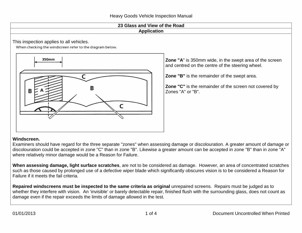
Heavy Goods Vehicle Inspection Manual
01/01/2013 1 of 4 Document Uncontrolled When Printed
23 Glass and View of the Road Application
This inspection applies to all vehicles.
Zone "A" is 350mm wide, in the swept area of the screen and centred on the centre of the steering wheel. Zone "B" is the remainder of the swept area. Zone "C" is the remainder of the screen not covered by Zones "A" or "B".
Windscreen. Examiners should have regard for the three separate "zones" when assessing damage or discolouration. A greater amount of damage or discolouration could be accepted in zone "C" than in zone "B". Likewise a greater amount can be accepted in zone "B" than in zone "A" where relatively minor damage would be a Reason for Failure. When assessing damage, light surface scratches, are not to be considered as damage. However, an area of concentrated scratches such as those caused by prolonged use of a defective wiper blade which significantly obscures vision is to be considered a Reason for Failure if it meets the fail criteria. Repaired windscreens must be inspected to the same criteria as original unrepaired screens. Repairs must be judged as to whether they interfere with vision. An ‘invisible’ or barely detectable repair, finished flush with the surrounding glass, does not count as damage even if the repair exceeds the limits of damage allowed in the test.

Heavy Goods Vehicle Inspection Manual
01/01/2013 2 of 4 Document Uncontrolled When Printed
23 Glass and View of the Road Application
When checking the view of the road from the driver’s seat, the view must not be obstructed by any changes to the original design such as the addition of stickers, pennants, cab decorations, stone-guards or other items which encroach more than 40mm into the swept area. Video monitors when fitted in the area at the top of the screen to give a view to the rear are acceptable provided they do not obstruct the swept area more than a rear view mirror would. Monitors fitted onto the dash must not encroach into the swept area by more than 40 mm. Official stickers are permitted to encroach more than 40mm if this is necessary to comply with other regulations, and include road fund licence, operators licence, section 19 permits, vehicle anti-theft scheme stickers issued by the Police Authority, toll payment tag/stickers, vehicle distance or lane indicator lenses and security passes. These should only be considered a reason for failure if they seriously restrict the view to the front. On many vehicles the original design will place things like instrument panel clusters inside the 40mm area swept by the wipers. Intrusions such as this which are original design features can be ignored, as can damage or unofficial stickers placed inside the 40mm limit but which are hidden by that feature. Some commercial vehicles have very large screens and have windscreen wipers which cover an area that have no practical use. For the purposes of the annual test, the area of the screen above a horizontal line taken from the driver’s eye position, assessed with the driver seated, looking forward in a comfortable upright driving position and with the seat, if adjustable, in its highest position can be ignored other than the area through which the driver is required to view a mirror (front mirrors on HGVs are not required to be viewed through the area swept by the wipers). Swept area means the area swept by the wipers in their normal operation and does not include any additional area of the screen covered by the wipers to reach the parked position or which the original manufacturer has designed as opaque.

Heavy Goods Vehicle Inspection Manual
01/01/2013 3 of 4 Document Uncontrolled When Printed
23 Glass and View of the Road Application
Examples of acceptable features which may intrude into the swept area of the wipers provided they do not seriously impair the driver’s view are:
Vehicle distance or lane indicator lenses Automatic windscreen wiper detectors Grooves in the windscreen designed to clean wiper blades Fresnel lens Split windscreens Wipers which park adjacent to a central pillar Driver’s aids such as blinds and their mountings. This includes manufacturer’s exterior fixed sun visors.
Examples of unacceptable features are: No smoking signs Maximum height signs Satellite navigation if not chassis makers original equipment (see example below) Maintenance information stickers Monitors which show the activities at the rear of the vehicle if not chassis maker’s original equipment.
Chassis makers original equipment - Pass Not chassis makers original equipment - Fail
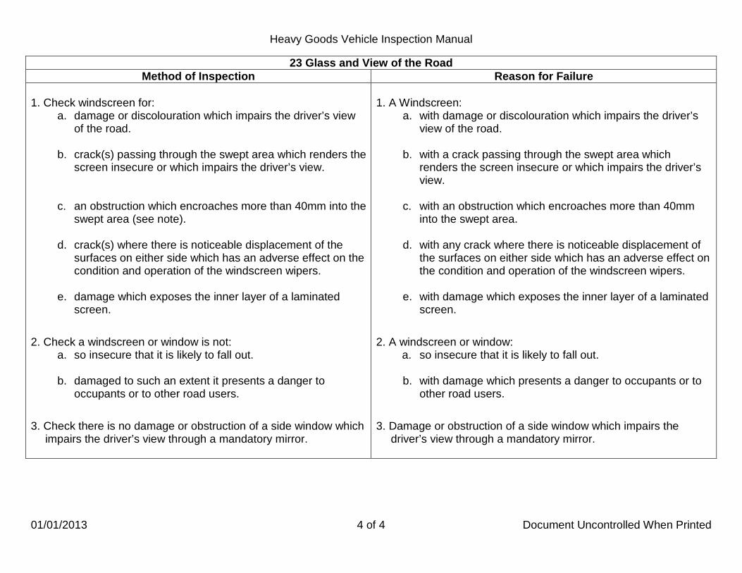
Heavy Goods Vehicle Inspection Manual
01/01/2013 4 of 4 Document Uncontrolled When Printed
23 Glass and View of the Road Method of Inspection Reason for Failure
1. Check windscreen for:
a. damage or discolouration which impairs the driver’s view of the road.
b. crack(s) passing through the swept area which renders the
screen insecure or which impairs the driver’s view. c. an obstruction which encroaches more than 40mm into the
swept area (see note).
d. crack(s) where there is noticeable displacement of the surfaces on either side which has an adverse effect on the condition and operation of the windscreen wipers.
e. damage which exposes the inner layer of a laminated
screen.
2. Check a windscreen or window is not: a. so insecure that it is likely to fall out. b. damaged to such an extent it presents a danger to
occupants or to other road users.
3. Check there is no damage or obstruction of a side window which impairs the driver’s view through a mandatory mirror.
1. A Windscreen:
a. with damage or discolouration which impairs the driver’s view of the road.
b. with a crack passing through the swept area which
renders the screen insecure or which impairs the driver’s view.
c. with an obstruction which encroaches more than 40mm
into the swept area. d. with any crack where there is noticeable displacement of
the surfaces on either side which has an adverse effect on the condition and operation of the windscreen wipers.
e. with damage which exposes the inner layer of a laminated
screen.
2. A windscreen or window: a. so insecure that it is likely to fall out. b. with damage which presents a danger to occupants or to
other road users.
3. Damage or obstruction of a side window which impairs the driver’s view through a mandatory mirror.

Heavy Goods Vehicle Inspection Manual
01/01/2013 1 of 1 Document Uncontrolled When Printed
25 Windscreen Wipers and Washers Application
This inspection applies to all vehicles except those with an opening windscreen or where an adequate view can be obtained by some other means. Wipers must be able to clear an adequate area of the screen to give the driver a view of the road to the front and in front of both sides of the vehicle. Washers must provide enough water to enable the wipers to clear the screen effectively. Frozen washers are to be considered ineffective. There is no requirement to check that wipers self park.
Method of Inspection Reason for Failure 1. Check switches that control windscreen wipers and or washers
are fitted and operational. 2. Check Wipers:
a. cover an adequate area. b. work continually when switched on.
c. blade(s) are fitted, secure and in an effective condition to
clear the screen. 3. Check Washers are effective.
1. Switches missing or defective. 2. Wipers:
a. do not move over an adequate area. b. do not work continually when switched on.
c. a blade missing, insecure or so deteriorated that it cannot
clear the screen effectively. 3. Washers ineffective.

Heavy Goods Vehicle Inspection Manual
01/01/2013 1 of 5 Document Uncontrolled When Printed
26 Speedometer/Tachograph Application
This inspection applies to all vehicles. A vehicle must have a tachograph fitted unless the presenter claims that it is exempt from the tachograph regulations. Exempt vehicles may have either a tachograph or a speedometer fitted. The check of tachograph seals is by visual assessment only.
All vehicles A tachograph exemption form must be completed for all vehicles deemed as tachograph exempt, unless the vehicle technical record shows the vehicle is exempt or it is declared on the application form. If the glass dial is cracked and this does not affect operation this is not a Reason for Failure but the presenter should be advised of the defect. If the time clock is inoperative this is a reason for failure under 1b (for the tachograph only not the speedometer). For vehicles fitted with a tachograph If the tachograph head cannot be opened or if the calibration plaque does not match the vehicle to which it is fitted it should be treated as if the plaque and any relevant seals were not there. If the vehicle identification on the calibration plaque does not correspond to the vehicle it is fitted to, the vehicle should be failed under RfF 2a. Should the identification refer to the registration mark, the technical record must be checked to ensure it was not a previous registration for the same vehicle. If no vehicle identification is displayed this is not a RfF, there is no requirement to display the registration mark on the calibration plaque. For vehicles required to be fitted with a tachograph The tachograph head must only be opened with the steering wheel in the straight ahead position and with the engine switched off. Installation/calibration plaques expire after 6 years for analogue, 2 years for digital. It is acceptable for the plaque to contain additional information (e.g. Registration Number, tyre pressures etc.). The plaque is designed to be tamper proof and should show signs of damage if it has been tampered with. The 2 year check is not part of this inspection for analogue tachographs only. However if the examiner notices this plaque is not displayed the presenter must be advised.

Heavy Goods Vehicle Inspection Manual
01/01/2013 2 of 5 Document Uncontrolled When Printed
26 Speedometer/Tachograph Application
Analogue tachographs The electronic check of the indicated ‘K’ factor is conducted under IM33 but if it differs from the prescribed factor by more than + 50 it may be a reason for rejection under this section, unless it complies with a further check contained in IM 33. Check tachograph DIL switch covers and all seals. It will be sufficient to check that they have an approved marking. It is not necessary to identify the sealer.
Digital tachographs Do not use the Stoneridge speed limiter test equipment on vehicles fitted with digital tachographs. For vehicles not required to be fitted with a tachograph where a tachograph is used as a speedometer If a tachograph is used in place of a speedometer (even if the vehicle is tachograph exempt) it is only required to be marked in kilometres per hour, although it may be dual marked in miles per hour also. Only where the tachograph is marked in KPH alone,will you be required to check the installation/calibration plaque for presence and condition, and the date of calibration is clearly visible. There is no requirement for a re-calibration of these systems after 6 years provided that the system has been
Check DIL switch covers and seals for presence and condition and that they are the correct type. It will be sufficient to check that they have an approved marking. It is not necessary to identify the sealer.
initially calibrated and sealed, and that the calibration plaque and necessary seals remain intact.
If a speed limiter is NOT required, or the speed limiter does not receive the speed signal from the tachograph head, it is only necessary to check the seals inside the tachograph head. There is no requirement for the gearbox sender unit to be sealed. The vehicle technical record will show if a vehicle is speed limiter exempt.
Vehicles fitted with Modular Tachographs There are presently two types of modular tachograph using encrypted sender units. They are VDO Keinzel 1324 and Stoneridge Electronics (formerly TVI) and are easily identified as they are shaped like a car radio.
Vehicles fitted with Digital and or Modular Tachograph systems have received type approval that permits the use of a 4 wire data transmission cable instead of an armoured cable provided it is used to connect an encrypted sender unit to the tachograph. When used in this arrangement the approval also does not require the cable end connections to be sealed. However, the sender unit itself is still required to be sealed to the gearbox.

Heavy Goods Vehicle Inspection Manual
01/10/2014 3 of 5 Document Uncontrolled When Printed
26 Speedometer/Tachograph Application
Where a print out from a digital tachograpgh cannot be obtained initially (because of a jammed or depleted roll) the presenter should be given the opportunity to rectify this before leaving the test station and the use of PRS would not be appropriate if the defect is rectified. Identification of Encrypted Sender Units These appear similar to other sender units and can be positively identified by the cream/beige colour of the sender unit 4 pin bayonet connector. This colour is the same whether the sender unit is the rotating type or a proximity type. It should be noted that when the cable is connected that only a small part of the cream/beige coloured connector is visible. For the VDO Keinzel 1324 there is an exception to the above colour code when the vehicle is fitted with a TELMA retarder, the socket housing will be The electronic check of the K Factor will be carried out as part of the procedure for IM 33 but any failure where the electronically indicated figure differs from prescribed ‘K’ factor by more than + or - 50 may be a Reason for Failure under 3.g, unless it complies with a further check contained in IM 33.
red.
If a vehicle is fitted with more than one tachograph and a speed limiter, the speed limiter should operate off all tachographs.
Plastic sleeve seals are acceptable but will require an embossed identification, (see example to left).
Tachograph plaques are required to be tamperproof; this is not a reason for Failure at annual test if they are not tamperproof.

Heavy Goods Vehicle Inspection Manual
20/03/2013 4 of 5 Document Uncontrolled When Printed
26 Speedometer/Tachograph Method of Inspection Reason for Failure
1. For all vehicles, check a speedometer or tachograph is:
a. fitted. b. complete and operative. c. able to be illuminated.
2. Check all vehicles fitted with a tachograph have: a. tachograph installation/calibration plaque present and
complete. b. a DIL switch cover present, complete and in good
condition. 3. For vehicles required to be fitted with a tachograph check:
a. tachograph scale is marked in kilometres per hour.
b. tachograph manufacturer’s serial number/data plaque present or showing an “e” marking. c. tachograph installation/calibration plaque is in date. d. where a digital tachograph is fitted that the size of drive
axle road tyres comply with calibration plaque. e. “K” factor plaque present. f. seal(s) are present, intact and of the mandatory type.
g. an analogue or modular tachograph that the
electronically indicated figure does not differ from prescribed ‘K’ factor by more than + or – 50.
h. a printout can be obtained from a digital tachograph.
1. For all vehicles, a speedometer or tachograph:
a. not fitted. b. incomplete, clearly inoperative, or with dial glass broken or
missing (see note in application). c. cannot be illuminated.
2. For all vehicles fitted with a tachograph: a. tachograph installation/calibration plaque missing or damaged. b. DIL switch cover missing, broken or damaged through
interference.
3. For vehicles required to be fitted with a tachograph: a. tachograph scale not marked in kilometres per hour. (There is
no requirement for tachographs to be marked in m.p.h.). b. tachograph manufacturer’s serial number/data plaque missing
or not showing an “e” marking. c. tachograph installation/calibration plaque out of date. d. where a digital tachograph is fitted the size of drive axle road
tyres do not comply with calibration plaque. e. “K” factor plaque missing. f. seal missing, broken or where a clearly “non mandatory” seal
has been fitted in place of an “official” seal. g. an analogue or modular tachograph where the electronically
indicated figure differs from prescribed ‘K’ factor by more than + or – 50.
h. unable to obtain a printout from a digital tachograph.

Heavy Goods Vehicle Inspection Manual
01/01/2013 5 of 5 Document Uncontrolled When Printed
26 Speedometer/Tachograph
Method of Inspection Reason for Failure 3. For vehicles required to be fitted with a tachograph check
(continued): i. the digital tachograph displays a ‘K’ factor reading the
same as that shown on the calibration plaque (there is no allowance/tolerance as with analogue type tachographs).
4. For vehicles not required to be fitted with a tachograph, where a
tachograph is fitted in place of a speedometer check: a. If a speed limiter is required (which is sensed from the
tachograph head): the presence of a seal, it is complete and of a mandatory type.
b. If a speed limiter is not the presence of a seal (within the tachograph head) and it is complete. Note: There is no requirement for the gearbox sender unit to be sealed.
required:
3. For vehicles required to be fitted with a tachograph (continued):
i. a digital tachograph that displays a ‘K’ factor reading different to that shown on the calibration plaque (there is no allowance/tolerance as with analogue type tachographs).
4. For vehicles not required to be fitted with a tachograph, where a
tachograph is fitted in place of a speedometer: a. If a speed limiter is required (which is sensed from the
tachograph head): seal missing, broken or where a clearly “non-mandatory seal has been fitted in place of an “official seal”.
b. If a speed limiter is not a seal (within the tachograph head) missing, broken, or
required:
where a clearly “non mandatory” seal has been fitted in place of an “official” seal. There is no requirement for the gearbox sender unit to be sealed.
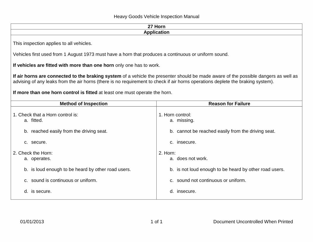
Heavy Goods Vehicle Inspection Manual
01/01/2013 1 of 1 Document Uncontrolled When Printed
27 Horn Application
This inspection applies to all vehicles. Vehicles first used from 1 August 1973 must have a horn that produces a continuous or uniform sound. If vehicles are fitted with more than one horn only one has to work.
If air horns are connected to the braking system of a vehicle the presenter should be made aware of the possible dangers as well as advising of any leaks from the air horns (there is no requirement to check if air horns operations deplete the braking system). If more than one horn control is fitted at least one must operate the horn.
Method of Inspection Reason for Failure 1. Check that a Horn control is:
a. fitted. b. reached easily from the driving seat.
c. secure.
2. Check the Horn:
a. operates. b. is loud enough to be heard by other road users.
c. sound is continuous or uniform.
d. is secure.
1. Horn control:
a. missing. b. cannot be reached easily from the driving seat.
c. insecure.
2. Horn:
a. does not work. b. is not loud enough to be heard by other road users.
c. sound not continuous or uniform.
d. insecure.

Heavy Goods Vehicle Inspection Manual
01/01/2013 1 of 1 Document Uncontrolled When Printed
28 Driving Controls Application
This inspection applies to all vehicles. From the drivers seat operate driving controls, except those for brakes and steering which are checked under other items, to see that they function correctly and are complete. Examples of driving controls which need to be inspected are:
1. Gear control. 2. Accelerator pedal. 3. Clutch pedal.
The list is not exhaustive. An air leak from a gear valve is not an RfF. An accelerator pedal anti slip provision missing or worn smooth is not an RfF.
Method of Inspection Reason for Failure 1. Check driving controls for:
a. security.
b. completeness.
c. fractures, cracks and corrosion.
d. obstructions or impediments in its travel. e. functioning correctly. f. the presence of rubbish or other items likely to interfere
with the proper control of the vehicle. g. the presence of a pedal anti-slip provision, its security
completeness and condition. 2. Check the designated engine stop control for presence and
operation.
1. A driving control: a. insecure.
b. incomplete.
c. fractured, cracked or excessively corroded. d. obstructed or impeded in its travel.
*e. obviously not functioning correctly.
f. with the presence of rubbish or other items likely to
interfere with the proper control of the vehicle.
g. pedal anti-slip provision missing, loose, incomplete or ineffective.
2. Engine stop control missing or inoperative.

Heavy Goods Vehicle Inspection Manual
01/01/2013 1 of 2 Document Uncontrolled When Printed
30 Steering Control Application
This inspection applies to all vehicles. Cracks in the plastic covering do not necessarily mean that a spoke is fractured. This inspection does not apply to drivers’ aid steering wheel knobs. Unless specified by the manufacturer vehicles fitted with power steering must be checked with the engine running. “Free Play” must not be confused with movement caused by the compression of steering joints etc. This operation should be carried out with light finger pressure to distinguish the feel of the steering wheel when it meets a resistance. Certain types of steering column might show some movement not due to excessive wear, e.g. those fitted with universal joints or flexible couplings. Free play at the steering rim in excess of 1/30 of the steering wheel diameter for a rack and pinion mechanism is considered a reason for failure. For other types of mechanism free play in excess of 1/5 of the wheel’s diameter is considered a Reason for Failure. The acceptable free play for a range of wheels is shown below.
WHEEL DIAMETER
RACK AND PINION STEERING
OTHER TYPES OF STEERING CONVENTIONAL
WITH STEERING WHEEL AHEAD OF THE RACK AND
WITH A NUMBER OF JOINTS
380mm (15”)
455mm (18”)
530mm (21”)
610mm (24”)
13mm (0.5”)
16mm (0.6”)
18mm (0.7”)
21mm (0.8”)
48mm (1.9”)
57mm (2.3”)
67mm (2.6”)
77mm (3.3”)
76mm (3”)
90mm (3.6”)
106mm (4.2”)
122mm (4.8”)

Heavy Goods Vehicle Inspection Manual
01/01/2013 2 of 2 Document Uncontrolled When Printed
30 Steering Control Method of Inspection Reason for Failure
1. Check the steering column:
a. has no excessive end float, when applying an upward and downward pressure to the steering wheel in line with the column.
b. has no excessive side play indicating a badly worn top bearing or insecure top mounting bracket, by pulling and pushing the rim.
c. flexible coupling and universal joint for condition and security.
d. coupling clamp bolt or locking device is present and secure. e. adjustment device condition.
2. Check the Steering Wheel:
a. security. b. condition.
c. hub retaining device is present and secure. 3. With the steered wheels in the straight ahead position lightly
rotate the steering wheel to the left and right and note the amount of free play.
1. Steering column:
a. with excessive movement of centre of steering wheel in line with the column (end float).
b. with excessive side play indicating a badly worn top bearing
or insecure top mounting bracket.
*c. flexible coupling or universal joint deteriorated, with
excessive wear or insecure. *d. couple clamp bolt or locking device missing or loose. e. with an adjustment device worn to such an extent that it
would render the column insecure.
2. Steering Wheel: *a. loose.
b. hub, spoke or rim fractured or cracked. The cover torn with jagged edges which may injure the driver.
c. hub retaining device not fitted or loose.
3. Free play in system which is outside the prescribed limits.

Heavy Goods Vehicle Inspection Manual
01/01/2013 1 of 6 Document Uncontrolled When Printed
33 Speed Limiter Application
This inspection applies to all vehicles which are required to be fitted with a speed limiter. Vehicles required to be fitted with a speed limiter are: A. A vehicle first used from 1 January 1988 with:
• a design gross weight of more than 12000kg and • a maximum speed capability exceeding 56 mph (90 km/h), if a speed limiter were not fitted must be fitted with a speed limiter set at a maximum stabilised speed of 56 mph (90 km/h).
B. A vehicle first used from 1 August 1992 until 30 September 2001 with:
• with a design gross weight of more than 7500kg and not exceeding 12000kg and • a maximum speed capability exceeding 60mph (96.5km/h) if a speed limiter were not fitted must be fitted with a speed limiter set at a maximum of 60 mph (96.5 km/h).
C. A vehicle first used from 1 October 2001 until 31 December 2004 with a Euro 3 Diesel or Gas engine (See note) with:
• a design gross weight of more than 3500kg and not exceeding 7500kg and • a maximum speed capability exceeding 90km/h if a speed limiter were not fitted must be fitted with a speed limiter set at a maximum stabilised speed of 56 mph (90 km/h) from 1 January 2007.
D. A vehicle first used from 1 October 2001 until 31 December 2004 with: • a design gross weight of more than 7500kg and not exceeding 12000kg and • a maximum speed capability exceeding 90 km/h if a speed limiter were not fitted must have a speed limiter set at 56 mph (90 km/h).
E. A vehicle first used from 1 January 2005 with: • a maximum design gross weight of more than 3500kg and not exceeding 7500kg • a maximum speed capability exceeding 90km/h if a speed limiter were not fitted must be fitted with a speed limiter set at a maximum stabilised speed of 90 km/h from 1 January 2008.
F. A vehicle first used from 1 January 2005 with: • a design gross weight of more than 7500kg and not exceeding 12000kg and • a maximum speed capability exceeding 90km/h if a speed limiter were not fitted must be fitted with a speed limiter set at a maximum stabilised speed of 90 km/h.

Heavy Goods Vehicle Inspection Manual
01/01/2013 2 of 6 Document Uncontrolled When Printed
33 Speed Limiter Application
Some vehicles first used from 1 October 2001 until 31 December 2004 may have been approved to Directive 70/220/EC or fitted with Euro 2 engines. These vehicles are exempt from the speed limiter fitting requirements for Group C. Where exemption is claimed at time of test this should be accompanied by an operator’s declaration of exemption and where necessary supported by manufacturer’s confirmation of emission test standard, unless the vehicle is marked speed limiter exempt on the technical record. All the following listed vehicles have already been confirmed by their manufacturers as being exempt and no further proof is required for these vehicles: Any Petrol engine or petrol engine converted to run on LPG Citroen Relay 2.0 litre and 2.2 litre HDi engines DAF 45, 7.5 ton vehicles (all) except DAF 45 marked as LF. (LF is marked on the N/S of the radiator grill.) Fiat Ducato with 2.0 litre engines (engine code RHV). Ford Transit (all). Isuzu models NPR, NQR, and NKR with T, V, W, X or 1(one) as the 10th
Iveco Cargo all, except vehicles with engine code F4AE---. VIN character.
Iveco Daily all, except vehicles with engine code F1CE---, 8140.43B, 8140.43N and 8140.43S with a PIC code ‘G.’ (the PIC code is applicable to the 8140.43S only, the PIC code can be found on the ID plate on the shut panel for the bonnet identified by the third character.) LDV (all). Mitsubishi Canter with ‘R’ as the 12th
Nissan Interstar all, except vehicles with engine code ZD3-A202, G9U-A754 & G9U-A724. VIN character.
Nissan Primastar All models. Peugeot Boxer 2.0 litre and 2.2 litre HDi engines. Renault Master all, except vehicles with engine code ZD3-A202, G9U-A754 & G9U-A724. Renault Trafic All models. Vauxhall/Opel Movano with E, F, G, J, K, L, M, N, P, T or W as the 7th VIN character. Vauxhall/Opel Vivaro (all). Volkswagen (all except 2.5lt/2.8lt 109bhp/158bhp engine codes AVR & AUH respectively). Other vehicles which are exempted by regulations are: Vehicles owned or used by the Secretary of State for Defence and used for naval, military or air force purposes. If the vehicle is being used the driver must be under the direct orders of a member of the armed forces of the Crown. Vehicles being used for fire brigade (in England and Wales fire and rescue authority), ambulance and police purposes. Vehicles which are an emergency tactical response vehicle operated by or on behalf of Her Majesty’s Prison Service and used primarily for the purpose of transporting people or equipment (or both) to restore order within Her Majesty’s prisons or immigration detention centres.

Heavy Goods Vehicle Inspection Manual
01/10/2014 3 of 6 Document Uncontrolled When Printed
33 Speed Limiter Application
If for any other reason the vehicle presenter claims a valid exemption that is different from the technical record, form VOSA 74 V2 must be completed. Check that a speed limiter plate is securely fitted in the driver’s compartment. It is acceptable for the plate to be fitted in the driver’s door jamb. If fitted on a window and facing outward the details must be able to be read by a person of average height. The character and composition of the plate and size of the lettering are not important provided the details are legible. It is acceptable for the limiter to be wired through the “ignition” switch but any other device which would allow disconnection of the speed limiter whilst driving is unacceptable. Early tachographs had covers with a masked area over the access port to interrogate tachograph. These are still to be found although the tachograph scheme has been instructed to cease the fitting of such. Do not remove this type of DIL switch cover at the time of test as it is easy to inadvertently make contact with one of the switches and completely alter the ‘K’ factor. This means that the test equipment cannot be used and the presenter should be asked to provide tachograph chart evidence of speed limiter operation as described below. Clear DIL switch covers are acceptable at the time of test, although once again they are no longer acceptable under the Tachograph approved scheme and centres should no longer fit them. Speed Limiter Integrity Check Using Electronic Device. Not applicable to vehicles fitted with digital tachographs. Refer to section 26 headed digital tachographs.
1. Open the tachograph head. If seals need to be removed from within the tachograph head then do so. Plug the speed simulator jack plug into the tachograph head and close the head. Seals can only be removed and replaced by approved tachograph sealing centres or authorised DVSA staff.
2. The machine will establish the pre set ’K’ factor. Check that this is within + or - 50 digits of the ’K’ factor displayed on the
tachograph calibration plaque. A number of manufacturers have dual marked plaques where the ‘W’ factor and the ‘K’ factor are the same and are in the format “W =K= “followed by the associated figure. Other configurations found are no ‘W’ or ‘K’ on the plaque but marked Imps / km or Impulses per kilometre, as the K factor is the number of electronic impulses required to record the distance of one kilometre travelled, this is acceptable.
3. Start engine and run at 1200-1500 rpm. Input a simulated speed to 80km/h. Check that the tachograph indicates the same
speed. Gradually increase the simulated speed in 1 km/h steps. Note the speed indicated on simulator’s digital display when the speed limiter operates. This can be identified by a reduction in the engine RPM, or a change in the engine note, or vibration indicating that the fuel supply is being reduced.

Heavy Goods Vehicle Inspection Manual
01/10/2014 4 of 6 Document Uncontrolled When Printed
33 Speed Limiter Application
If it is found that the indicated figure differs by more than ±50 from the prescribed “K” factor a further check should be made. In line with normal procedures where the ‘K’ factor indicated by the electronic device does not exactly match the displayed ‘K’ factor, input the displayed 'K' from the plaque into the electronic device. It is imperative that the tachograph head is closed before the remainder of the test is conducted so that no damage to the tachograph can take place should the vehicle’s steering wheel be accidentally turned. Set the simulated speed to 80 km/h and check the speed indicated by the tachograph. Note the difference, if any, in speed between that displayed on the electronic device and the tachograph. If there is a difference in the electronic device’s simulated speed and the speed indicated on the tachograph, and this difference is greater than 5km/h, either higher or lower, then the vehicle should be failed under Reason for Failure 3g of IM 26 as this defect relates to the tachograph rather than the speed limiter. Continue to undertake a check of the vehicle’s speed limiter. Remember to use the electronic device’s simulated speed as the indication of the true road speed at which the road speed limiter operates. On some vehicles, the electronic device will be unable to indicate the speed at which the speed limiter operates. Under these circumstances tachograph chart evidence of the vehicle while in service can be used to verify the operation of the speed limiter. The voluntary submission of 5 consecutive tachograph charts from the previous 28 working days can be used to establish the maximum operational speed. The vehicle should be failed for Reason for Failure 3a or 3b if the tachograph chart shows a speed trace of more than 95 km/h for vehicles in Groups A,C,D,E and F and of more than 106.5 km/h for vehicles in Group B. The vehicle must have exceeded this speed for at least ten minutes. If the speed simulator is unable to be used, and there are no tachograph charts available for inspection, the vehicle should be passed. DVSA Enforcement should be advised of the inability to check this test item. Only speed limiter calibration certificates are acceptable at retest. If a certificate relating to the tachograph is presented the vehicle must be physically rechecked.

Heavy Goods Vehicle Inspection Manual
01/10/2013 5 of 6 Document Uncontrolled When Printed
33 Speed Limiter Application
The inspection of speed limiters is only for the parts which are visible without dismantling. It is acceptable to receive verification from a speed limiter calibrator that a vehicle can not exceed the speed requirement for the instillation of a speed limiter. A relevant exemption form should be completed and forwarded to record section at Ellipse, Padley Road, Swansea. Speed limiter inspections should not be carried out on vehicles with AS Tronic/Optidrive gearboxes. ‘K’ plaques placed over seals. Do not remove these plaques and use tachograph charts as evidence of the speed. Inform the enforcement staff so they can contact the tachograph centre of the incorrect practice. The 13-18 tachograph can suffer from earth problems, this can be cured by moving the vehicle, ensure the presenter moves the vehicle if this is required. When performing the speed limiter check, if the tachograph seals are clearly non mandatory or missing from the head do not perform the speed limiter inspection and fail the vehicle under IM 26.3.f. Plastic speed limiter seals are acceptable if they are properly marked with a sealer identification. Because of the way the Romatic Speed Limiter operates if you encounter an over speed situation please use the tachograph charts for confirmation that the limiter is defective before failing vehicles fitted with this device.
Method of Inspection Reason for Failure 1. Check the Speed Limiter Plate is:
a. fitted. b. secure.
c. conspicuously positioned.
d. clearly and indelibly marked with the speed at which the
speed limiter has been set. Acceptable in mph or km/h.
1. Speed Limiter Plate:
a. missing. b. insecure.
c. not in a conspicuous position.
d. not clearly and indelibly marked with the set speed.

Heavy Goods Vehicle Inspection Manual
01/10/2013 6 of 6 Document Uncontrolled When Printed
33 Speed Limiter Method of Inspection Reason for Failure
2. Check the Set Speed marked on Speed Limiter Plate:
a. 90km/h (56 mph) for a vehicle described in Application section Groups A, C, D, E & F.
b. 96.5 km/h (60 mph) for a vehicle described in Application
section Group B.
3. Check the response speed of the limiter.
4. Check the Speed Limiter is: a. fitted. b. secure.
c. operating correctly and actuating rods/cables are
connected and not damaged.
d. connected by authorised means and the wiring is not easily disconnected.
e. tamperproof, a device is fitted and is not defective and has
not been interfered with.
2. Set Speed marked on Speed Limiter Plate greater than:
a. 90km/h (56 mph) for a vehicle described in Application section Groups A, C, D, E & F.
b. 96.5 km/h (60 mph) for a vehicle described in Application
section Group B.
3. Response speed of: a. 92 km/h or more for a vehicle described in Application
section Groups A, C, D, E & F. b. 102 km/h or more for a vehicle described in Application
section Group B.
4. Speed Limiter: a. not fitted. b. insecure.
c. actuating rods/cables disconnected or damaged so that
the operation is obviously affected.
d. wiring disconnected or can easily be disconnected by unauthorised means.
e. tamperproof device missing or defective or showing
obvious signs of interference.

Heavy Goods Vehicle Inspection Manual
01/01/2013 1 of 2 Document Uncontrolled When Printed
34 Pressure/Vacuum Warning and Build Up Application
This inspection applies to all vehicles, except those with an unladen weight of less than 3050kg where the vacuum reservoir is coupled direct to the engine induction manifold. These vehicles do not require a pressure/vacuum warning device (if it is not possible to determine the unladen weight of a vehicle, the presenter should be given the opportunity to produce some evidence of the unladen weight before failing the vehicle). Vehicles used from 1 April 1983 can be fitted with either a visual warning device or an audible warning device. If both are fitted only one need work. Vehicles first used before 1 April 1983 must be fitted with a visual warning device. If an audible warning device is also fitted this is considered to be an addition to the mandatory requirement. A number of vehicles, among them Mercedes 515, 609, 612, 614, 709 and Iveco Daily models were approved without a warning device and should not be failed for a warning device not fitted. If there is no reservoir in a vacuum system a warning device is not required. If the vehicle has full power hydraulic brakes, gauges are not normally fitted and there are no appreciable sounds when the brakes are applied. To check for the compliance with item 2 in MoI use the procedure shown in Item 71. If gauges are not marked, take 3 bar (45 psi) for air systems and 25 to 30cm (10 to 12 Inches) for vacuum systems as indicating minimum effective working condition. The time to reach minimum effective working pressure should normally be within 3 minutes for pressure systems and 1 minute for vacuum systems. With Type Approved vehicles designed to draw a trailer a build-up time of 6 minutes is acceptable. If, however, the time recorded for the vehicle is appreciable longer than expected from that type of vehicle, this should be taken to indicate undue wear or a defect in the equipment.

Heavy Goods Vehicle Inspection Manual
01/01/2013 2 of 2 Document Uncontrolled When Printed
34 Pressure/Vacuum Warning and Build Up Method of Inspection Reason for Failure
1. Check the mandatory visual warning device:
a. can be seen by the driver in all lighting conditions. b. is fitted and is working correctly.
2. Deplete the air or vacuum system by applying the foot brake,
when the warning device operates there must be two further assisted brake applications.
3. Fully deplete the system and run the engine at just below governed speed and note the time for the warning device to show minimum effective working condition.
1. A mandatory visual warning device:
a. can not be seen by the driver in all lighting conditions. b. not fitted or not working correctly.
2. Not enough pressure or vacuum to give at least two fully
assisted brake applications after the warning device has indicated minimum effective working conditions.
*3. Time to reach minimum effective working pressure is more than 3 minutes for pressure systems and 1 minute for vacuum
systems (6 minutes for type approved vehicles designed to draw a trailer).
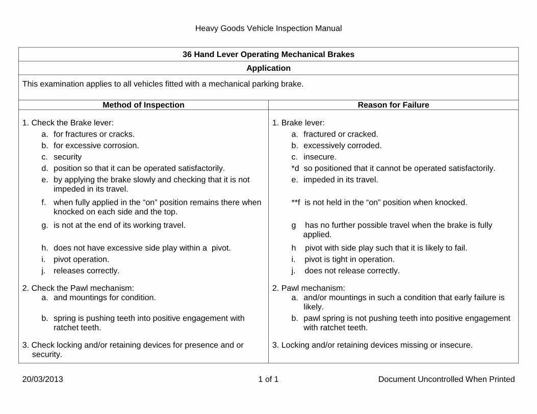
Heavy Goods Vehicle Inspection Manual
20/03/2013 1 of 1 Document Uncontrolled When Printed
36 Hand Lever Operating Mechanical Brakes Application
This examination applies to all vehicles fitted with a mechanical parking brake.
Method of Inspection Reason for Failure
1. Check the Brake lever: a. for fractures or cracks. b. for excessive corrosion. c. security d. position so that it can be operated satisfactorily. e. by applying the brake slowly and checking that it is not
impeded in its travel. f. when fully applied in the “on” position remains there when
knocked on each side and the top. g. is not at the end of its working travel. h. does not have excessive side play within a pivot. i. pivot operation. j. releases correctly.
2. Check the Pawl mechanism: a. and mountings for condition. b. spring is pushing teeth into positive engagement with
ratchet teeth.
3. Check locking and/or retaining devices for presence and or security.
1. Brake lever: a. fractured or cracked. b. excessively corroded. c. insecure. *d so positioned that it cannot be operated satisfactorily. e. impeded in its travel. **f is not held in the “on” position when knocked. g has no further possible travel when the brake is fully
applied. h pivot with side play such that it is likely to fail. i. pivot is tight in operation. j. does not release correctly.
2. Pawl mechanism: a. and/or mountings in such a condition that early failure is
likely. b. pawl spring is not pushing teeth into positive engagement
with ratchet teeth.
3. Locking and/or retaining devices missing or insecure.

Heavy Goods Vehicle Inspection Manual
20/03/2013 1 of 1 Document Uncontrolled When Printed
37 Service Brake Pedal Application
This examination applies to all vehicles. Power operated braking systems where the foot valve is fully open before the pedal is fully depressed do not require any reserve travel.
Method of Inspection Reason for Failure
1. Check Brake pedal:
a. anti -slip provision presence, security and condition. b. condition. c. does not foul other parts of the vehicle. d. has sufficient reserve travel when fully depressed.
2. Check Brake pedal and assembly:
a. is secure. b. Is complete, with no fractures, cracks, or corrosion. c. pivot operation. d. releases correctly.
1. Brake pedal:
a. anti-slip provision missing, loose, incomplete or ineffective. b. has excessive side play.
*c. fouling other parts of the vehicle. d. insufficient reserve travel when fully depressed.
2. Brake pedal or assembly:
a. insecure. *b. incomplete, fractured, cracked, or corroded. c. pivot is tight in operation. d. does not release correctly.

Heavy Goods Vehicle Inspection Manual
01/01/2013 1 of 6 Document Uncontrolled When Printed
38 Service Brake Operation Application
This examination applies to all vehicles and trailers. Vehicles and trailers on which anti-lock brakes are mandatory
Type of Vehicle Date
Motor vehicles with design GVW greater than 16000kg and authorised to tow a semi-trailer or a centre axle drawbar trailer with total design axle weights greater than 10000kg or a drawbar trailer with design GVW greater than 10000kg. (an O4 trailer) See examples 1 and 2 below to determine whether a motor vehicle needs antilock brakes
First used from 1 April 1992 and up to 30 April 2002
Motor vehicle with design GVW greater than 3500kg First used from 1 May 2002
Semi-trailers and centre axle drawbar trailers with a design total axle weight of more than 10000kg Manufactured from 1 October 1991
Semi-trailers and centre axle drawbar trailers with a design total axle weight of more than 10000kg and which do not have a load sensing valve
Manufactured from 1 October 1982 to 30 September 1991
Semi-trailers and centre axle drawbar trailers with a design total axle weight of more than 3500kg Manufactured from 1 May 2002
Full drawbar trailers (turntable type) with a design GVW of more than 10000kg Manufactured from 1 October 1991
Full drawbar trailers (turntable type) with a design GVW of more than 10000kg and which do not have a load sensing valve
Manufactured from 1 October 1982 to 30 September 1991
Full drawbar trailers (turntable type) with a design GVW of more than 3500kg Manufactured from 1 May 2002
Anti lock Brake exempt vehicles A public works vehicle which has a maximum design GVW of 7500kg and which is specifically designed for use and used solely for the purpose of street cleansing.

Heavy Goods Vehicle Inspection Manual
01/01/2013 2 of 6 Document Uncontrolled When Printed
38 Service Brake Operation Application
How to determine if a drawing vehicle first used from 1st April 1992 and before 1 May 2002 needs antilock brakes. Example 1
Semi-Trailer or Rigid and Drawbar Trailer
DGVW 18000kg DGTW greater than 28000 - (DGTW-DGVW>10000) Anti-lock brakes required. Example 2
Semi-Trailer or Rigid and Drawbar Trailer
DGVW 18000kg GTW 27000kg (DGTW-DGVW<10000) Anti-lock brakes may be required if:
1. the drawing hitch is rated at more than 10000kg or 2. the tractor is presented for test with a semi-trailer which has Total Axle Weight greater than 10000kg or 3. the drawing vehicle is presented for test with a trailer which has DGVW greater than 10000kg
The tow hitch should have a manufacturer’s identification plate showing the hitch capacity. For some brake systems a small amount of creep may be due to elasticity in the brake components. For test purposes it will only be possible to check the static part of the warning light sequence. Some systems require movement of the vehicle but this is not part of the test.

Heavy Goods Vehicle Inspection Manual
01/10/2014 3 of 6 Document Uncontrolled When Printed
38 Service Brake Operation Application
If a trailer is submitted for test coupled to a motor vehicle which has no power supply for the trailer anti-lock system the test should be suspended on the grounds that the trailer has not been accompanied by a suitable drawing vehicle. The presenter should be informed of this on form VTG12.
If a trailer does not have a warning light, this is acceptable provided that the drawing vehicle has a trailer warning light fitted in the cab. If neither the tractor nor trailer has a warning light and there is a separate connector for the anti-lock system the test should be suspended as described above. If neither has a warning light and the trailer anti-lock is operated through the stop lamp circuit the trailer should be failed under Reason for Failure 5a.
Vehicles and trailers fitted with ABS are not required to have a LSV. However, if an LSV is fitted and known to be a standard fitment this is a RfF if it is removed or disconnected refer to IM59. There is no requirement to check the colour of Malfunction Indicator system warning lamps.
ABS only vehicles
ABS, ABS/EBS and ABS/EBS/ESC requirements
Vehicles fitted with ABS only must have a mandatory warning malfunction indicator lamp (MIL) that illuminates when the system is energised (ignition or battery master switch on). It can be any colour, though they are usually red, yellow or amber. It must go out after a short period or when the engine is started but can then come back on and remain on until the vehicle speed exceeds approximately 5 kph (3 mph). It is not necessary to move the vehicle to check the speed-activated function provided the lamp does go off momentarily. Trailers fitted with ABS must have either; a warning lamp (usually green and fitted on the trailer headboard), or if this is not present then there must be a trailer ABS warning lamp in the motor vehicle cab of any colour separate from the vehicle warning lamp. If trailer ABS warning lamps are fitted to both vehicle and trailer both systems must work (on some trailers the trailer warning lamp may be extinguished when the ISO7638 cable is fitted).
Other lamps of the same or different colours showing e.g. that trailers are not connected, or are not fitted with ABS may also be fitted to motor vehicles. These are not mandatory and are for information purposes only. If these are illuminated it is not an RfF. It is important to establish that a lit warning lamp is actually showing an ABS defect, and is not an ABS information lamp. The Driver Handbook may be used to establish the function of a lamp.

Heavy Goods Vehicle Inspection Manual
01/10/2013 4 of 6 Document Uncontrolled When Printed
38 Service Brake Operation Application
ABS/EBS equipped vehicles Vehicles fitted with ABS and EBS must have mandatory red and amber/yellow MILs fitted. Drawing vehicles must be fitted with a
The red MIL illuminates if there is a foundation brake fault or the prescribed minimum brake performance cannot be met. The red MIL must illuminate with system initialisation though this may not be clearly evident as in some cases the sequence is extremely fast and may be missed. In this circumstance if modulator cycling can be heard it is acceptable to pass the vehicle. If a red MIL stays lit or is flashing this is a reason for failure.
separate amber/yellow MIL for the trailer, though one red MIL may be shared between tractor and trailer. If separate tractor and trailer Red MILs are fitted they are both required to work.
The amber/yellow lamp illuminates if there is an electronic fault The amber/yellow MILs must illuminate with system initialisation though this may not be clearly evident as in some cases the sequence is extremely fast and may be missed. In this circumstance if modulator cycling can be heard it is acceptable to pass the vehicle. If the MIL stays lit this is a reason for failure. If the MIL illuminates on system initialisation then goes out and then flashes this should be advised. ABS/EBS/ESC equipped vehicles Motor vehicles fitted with ESC must have a separate amber/yellow MIL fitted apart from those used to signal EBS electronic faults. One lamp covers both the motor vehicle and any trailer fitted with ESC towed. The ESC lamp will be illuminated when the system is switched off, when the system is operating or if a fault is present. It is not required to light up on system energisation, but if it does this is acceptable provided it then goes out after a short period or when the engine is started. If the vehicle has a switch to manually disable the ESC function, it must not be possible for the switch to be left in the “off” position and the ESC function must be automatically reinstated every time the system is re-energised (ignition turned on.)
Electronic Stability Control Systems are commonly referred to as ESC, but may also be known as ESP/RSC or some other acronym. The MIL for these systems may take various forms and a vehicle should only be failed when the tester is certain that an illuminated lamp indicates an ESC malfunction. This may require reference to the owner’s handbook if one is available.

Heavy Goods Vehicle Inspection Manual
20/03/2013 5 of 6 Document Uncontrolled When Printed
38 Service Brake Operation Method of Inspection Reason for Failure
1. Air pressure or vacuum systems: With reservoir at maximum pressure or vacuum, fully depress the pedal and note the change in gauge readings to see if they give indications of a leak in the system.
2. Hydraulic systems (other than full power systems), fully depress the pedal and keep it depressed under steady pressure and check: a. that the pedal does not creep down under full pressure. b. there is no sponginess.
3. Brake systems assisted by engine vacuum: Deplete the vacuum, partly depress the pedal, start the engine, and check if the pedal can be felt to dip.
4. Full pressure hydraulic systems: Check that the system pressure is maintained for at least 10 minutes when the brakes are off and the engine is stopped. Loss of pressure will be indicated by the operation of the low pressure warning device (warning light or appearance of semaphore "flag" device).
1. Air pressure or vacuum systems gauge reading drops when pedal depressed indicating a leak in the system.
2. Hydraulic systems (other than full power systems):
a. pedal creeps down when depressed. b. sponginess when pedal depressed.
*3. Pedal does not dip when engine started, indicating lack of assistance for brake systems assisted by engine vacuum.
4. Full pressure hydraulic system pressure is not maintained for 10 minutes when the brakes are off and the engine is stopped.

Heavy Goods Vehicle Inspection Manual
01/07/2013 6 of 6 Document Uncontrolled When Printed
38 Service Brake Operation Method of Inspection Reason for Failure
5. If the vehicle/trailer is fitted with an ABS or ABS/EBS or ESC system, check that required warning lamps: a. are fitted. b. illuminate as required when ignition switched on. c. do not indicate a fault.
6. Vehicles and trailers fitted with ABS or ABS/EBS or ESC check: a. the presence and condition of all visible system
components. b. the condition of all visible system wiring. c. all system components for any inappropriate repair or
modification. d. the condition and operation of any switch fitted to turn the
ESC system on and off.
7. On Vehicles and trailers both fitted with ISO 7638 (ABS/EBS) lead sockets check an ISO 7638 connecting lead is fitted and being used.
8. On a vehicle or trailer on which anti-lock brakes are mandatory check that an ABS system is fitted.
5. Any of the required ABS or ABS/EBS or ESC warning lamps:
a. are missing. b. do not illuminate as required when ignition switched on. c. indicate a fault.
6. Vehicles and trailers fitted with ABS or ABS/EBS or ESC: a. a system component obviously missing or excessively
damaged. b. system wiring excessively damaged. c. a system component inappropriately repaired or modified. d. an ESC system switch insecure or faulty or which does not
allow automatic resetting of the ESC function to “on” at system energisation.
7. On vehicles and trailers both fitted with ISO 7638 (ABS/EBS)
lead sockets an ISO 7638connecting lead not fitted or being used.
8. A system not fitted to a vehicle where it is mandatory.

Heavy Goods Vehicle Inspection Manual
01/01/2013 1 of 1 Document Uncontrolled When Printed
39 Hand Operated Brake Control Valves Application
This examination applies to all hand operated valves on vehicles which operate secondary brakes, trailer brakes, spring brakes and lock actuators. It also applies to trailers fitted with hand operated spring brake valves. Certain air valves are subject to a slight amount of leakage and this is not a reason for failure.
Method of Inspection Reason for Failure 1. Check the Control valve:
a. on a motor vehicle is capable of being operated from the driving position.
b. is secure.
c. condition.
d. is unimpeded in its travel.
e. does not leak.
f. condition of gate or lever locating mechanism. g. functions correctly.
1. Control valve:
a. on a motor vehicle unable to be operated from the driving position.
b. insecure.
c. fractured, cracked, damaged or excessively corroded.
*d impeded in its travel. e leaking.
f excessive wear in the gate or lever locating mechanism.
*g malfunctioning.

Heavy Goods Vehicle Inspection Manual
01/01/2013 1 of 2 Document Uncontrolled When Printed
41 Condition of Chassis Application
This inspection applies to all vehicles and trailers. For integral construction the term chassis should also be taken to apply to the underframe. For vehicles without a chassis those parts of the body must be examined which take the place of the chassis. A missing chassis crossmember is not a reason for failure but it is subject to notifiable alteration procedure which may result in a vehicle being down plated. When assessing corrosion it must only be regarded as a failure if it is sufficiently advanced to obviously impair the strength of a load bearing member. RfF 2 also includes sliding bogies and their locking mechanisms. It does not include the operating mechanism to move the bogie (these are normally air brake chambers) unless detachment is likely when IM74 should be used. Seddon 6 x 2 has a ‘H’ section crossmember fitted forward of the drive axle, there are 2 holes in the bottom flange on each side of the chassis frame and crossmember which were originally for securing the steel spring suspension front spring bracket to the chassis frame. When air suspension is fitted there is no requirement to fit bolts in these 2 holes.

Heavy Goods Vehicle Inspection Manual
01/01/2013 2 of 2 Document Uncontrolled When Printed
41 Condition of Chassis
Method of Inspection Reason for Failure 1.Check all main members, cross members and outriggers which
have load restraining devices attached (e.g. twistlocks) for:
a. fractures or cracks. b. advanced corrosion.
c. deformation.
2. Check frame and/or cross member fastenings for:
a. security of flitch plates and fastenings. b. condition of welding.
3. On integral bodied vehicles and trailers where the body panels
provide an important part of the strength of the vehicle check any Integral body replacement panels:
a. are of a suitable material. b. are adequately secured by an appropriate method.
1. Any main or cross member or outrigger which has a load
restraining device attached:
a. fractured or cracked or b. with advanced corrosion or
c. deformed
so that the control of the vehicle is likely to be affected or the load will become insecure. 2. Frame and/or cross member fastenings:
a. insecure flitch plates and/or fastenings or b. a weld breaking away
so that the control of the vehicle is likely to be affected or the load will become insecure. 3. Integral body replacement panels:
a. of an obviously unsuitable material. b. not adequately secured by an appropriate method.

Heavy Goods Vehicle Inspection Manual
20/03/2013 1 of 1 Document Uncontrolled When Printed
42 Electrical Wiring and Equipment Application
This inspection applies to all vehicles and trailers. If the battery is only held in place by the cables and by a lip on the carrier this cannot be considered to be secure. Where it is not possible to inspect batteries for condition and leaks every effort should be made to inspect the area where the batteries are installed to confirm there are no signs of leakage. When checking the condition and security of the wiring, care needs to be taken when inspecting the high voltage systems of Hybrid Electric Vehicles. These high voltage wires are colour coded orange.
Method of Inspection Reason for Failure
1. Check all visible wiring for: a. condition and security. b. positioning so that it is unlikely to be chafed or damaged
by heat. 2. Check the battery and carrier for:
a. security. b. condition.
3. Check switches controlling obligatory lights for security and function.
4. Check trailer electrical sockets for: a. security. b. damage or deterioration.
5. Check all power train equipment for: a. security. b. risk of fire or injury.
1. Wiring: a. not adequately insulated or secured. b. positioned so that it is chafing or likely to be damaged by
heat. 2. Battery:
a. and/or carrier insecure and likely to become displaced. b. case leaking.
3. Switch controlling an obligatory light insecure or malfunctioning. 4. A trailer electrical socket:
a. insecure. b. damaged or deteriorated to the extent that the connecting
lead could not be securely connected. 5. A power train:
a. insecure. b. presents a risk of fire or injury.

Heavy Goods Vehicle Inspection Manual
01/01/2013 1 of 1 Document Uncontrolled When Printed
43 Engine and Transmission Mountings Application
This inspection applies to all vehicles, including Hybrid Electric Vehicles. Where there is separate power train equipment this should be treated as an engine/transmission. There will only be a failure under this item if a mounting is no longer capable of performing its function of location and support. Serious fractures in clutch or bell housings which affect the security of the engine or gearbox are a reason for failure.
Method of Inspection Reason for Failure
1. Check condition of mountings and subframes and their
installation to the chassis or underframe for:
a. security. b. cracks or fractures.
c. deterioration.
1. Any mounting or subframe:
a. loose. b. cracked or fractured.
c. badly deteriorated.

Heavy Goods Vehicle Inspection Manual
01/01/2013 1 of 1 Document Uncontrolled When Printed
44 Oil Leaks Application
This inspection applies to all vehicles and trailers. Check without operating any equipment other than the engine which may be run at tick-over speed. Very bad oil leaks are a reason for refusing to carry out the test. If the test is suspended for this reason the presenter will be notified of this using form VTG12. Temporary means of preventing leaked oil reaching the ground such as fabricated drip trays consisting of sheet metal supported by wire strands are not acceptable. This does not apply to permanent fittings such as drip trays for feed pipes on tankers. Fabricated repairs to an oil pipe which effectively stop an oil leak are acceptable.
Method of Inspection Reason for Failure
1. Check for leakage of any type of oil other than fuel oil.
*1. Any oil leak from any assembly which can deposit oil at a rate
of a 75mm diameter pool in 5 minutes or a number of leaks which collectively would deposit oil at the same rate.

Heavy Goods Vehicle Inspection Manual
01/01/2013 1 of 2 Document Uncontrolled When Printed
45 Fuel Tanks and System Application
This inspection applies to all fuel tanks which are permanently attached to vehicles and to trailers, including gas fuel tanks and cylinders, bottles and other types of fuel container. Seepage is not a reason for failure. Fabricated and "emergency" fuel caps are acceptable provided that they function correctly. Where possible the tank cap should be opened to check the sealing arrangements. Very bad fuel leaks are a reason for refusing to carry out the test. If the test is suspended for this reason the presenter will be notified of this using form VTG12. If the vehicle is powered by gas and suffers a leak this should be treated in the same manner as a normal fuel leak and VTG12 action taken. The vehicle should be moved to a well ventilated area away from people and buildings. If the leak is of a serious nature evacuate the building and call Health and Safety Branch.
It is not necessary to run the engine but if a leak is present when the engine is running the vehicle should be failed under RfF3a. It is not necessary to run combustion heaters as part of this inspection.

Heavy Goods Vehicle Inspection Manual
01/10/2014 2 of 2 Document Uncontrolled When Printed
45 Fuel Tanks and System
Method of Inspection Reason for Failure 1. Check the fuel tank for security. 2. Check tank straps and supports for:
a. condition and presence. b. security and strength
3. Check Fuel System for :
a. leaks. b. condition of pipes and that they are complete and secure.
c. positioning of pipes so that they are unlikely to be fouled
by moving parts. 4. Check Filler Cap for:
a. presence. b. security:
• by a positive means, or • such that pressure is maintained on the sealing
arrangement.
c. presence and condition of the sealing washer and that the mounting flange/sealing method is effective.
**1. Tank so insecure on its mountings that it is likely to drop
away partially or completely when the vehicle is used. 2. A tank strap or support:
a. broken or missing.
**b so insecure or weakened that the tank is likely to drop away partially or completely when the vehicle is used.
3. Fuel System: *a leaking.
b pipes so damaged (restricted/chafed), insecure or with an inadequate repair such that they are likely to fail and leak which would cause danger to persons on the vehicle or to other road users.
c pipes damaged or so positioned that they are fouled by
moving parts of the vehicle.
4. Filler Cap: **a missing.
**b does not fasten securely: • by a positive means, or • such that pressure is not maintained on the sealing
arrangement.
**c sealing washer torn, deteriorated or missing, or a mounting flange/sealing method defective such that leakage of fuel is possible.

Heavy Goods Vehicle Inspection Manual
01/01/2013 1 of 1 Document Uncontrolled When Printed
46 Exhaust Systems Application
This inspection applies to all vehicles. Where a diesel engined vehicle is failed for exhaust system leaking, the smoke emission test could be affected by the induction of air into the exhaust system. When presented for retest the emission test should be rechecked. Slight leaks are acceptable. Check for the presence of the silencer and assess its effectiveness in reducing, so far as is reasonable, noise caused by the exhaust. An excessively deteriorated exhaust is not a reason for failure providing RfF 1.a and 1.b do not apply.
Method of Inspection Reason for Failure
1. Check the condition of the exhaust pipes and silencers for:
a. security. b. leaks.
c. position, so that fumes are unlikely to enter the driver’s
cab. 2. Check the exhaust silencer for:
a. presence. b. effectiveness.
1. An exhaust system:
a. so insecure that it might fall away partially or completely when the vehicle is in use.
b. leaking.
c. positioned so that fumes are likely to enter the driver’s
cab. 2. An exhaust silencer:
a. missing. b. ineffective.

Heavy Goods Vehicle Inspection Manual
01/01/2013 1 of 6 Document Uncontrolled When Printed
48 Suspension Application
This inspection applies to all vehicles and trailers. Leaf spring systems: • The fail criterion is that the leaves are so misaligned that each leaf is not taking a reasonable proportion of the load. • A leaf spring with a fracture or crack on the curled section which prevents the axle moving in the event of main leaf failure is a
reason for failure. • A "U" bolt should be regarded as loose if there is clear visual evidence that it is not properly fulfilling its function of securing a
spring and before it can do so it needs remedial action. • Surface cracks on laminated semi-elliptical springs are not a RfF. • It is permissible to have a larger road spring on one side of a vehicle than the other.
Spring Pins: • The maximum permissible wear in a pin and/or mounting is 2mm for a 12mm diameter pin and 1/8 of the diameter for larger
assemblies. For a threaded pin it is the diameter of the threaded part which should be taken into account when assessing wear. These criteria should not be used when checking rubber bushes which should be checked for deterioration of the rubber which could result in excessive movement.
• The maximum side play must not exceed 6mm. This does not apply to a threaded pin and mounting assembly or to rubber bushes or to single spring bogie suspensions.
• Where an anchor/shackle pin is secured at one end the maximum amount of movement at the free end should not exceed 1mm for smaller assemblies, increasing to 2mm for larger assemblies.
Slipper brackets: • Rebound pins where fitted as standard should be correctly located. • Worn slipper brackets are a RfF when worn to the extent they could, at the time of the inspection, clearly affect the movement or
correct location of the road spring (or have allowed the spring leaf to damage the chassis). Air/Fluid systems: • When assessing the significance of leaks it should be remembered that certain pneumatic components are subject to some
degree of leakage. Slight seepage producing a thin film of oil on the component is not a Reason for Failure but any sign of dripping is unacceptable.
• Exposure of air bag structural cords is acceptable providing that they are not damaged to such an extent the unit is likely to fail. • An air bag for holding a lift axle in the raised position must be considered against the same criteria as any other suspension air
bag.

Heavy Goods Vehicle Inspection Manual
01/01/2013 2 of 6 Document Uncontrolled When Printed
48 Suspension Application
Insecurity of attachment points can best be assessed when the steering and/or brakes are operated. A fractured and or repaired air bag pedestal if performing satisfactorily and not damaging the air bag is not a RfF. Independent suspension must be jacked to remove the weight from the suspension joints (suspension hanging freely). Trailers fitted with HD shock absorbers are not required to be fitted with check straps. Scania vehicles with air suspension have attachment points for a retaining chain, the omission of the chain is not an RfF. Tag axles with disabled lift facilities are not an RfF, these may also have the lift operation air bag removed. Shock Absorbers/Anti Roll Bars:
• Slight seepage producing a thin film of fluid on a shock absorber is not a reason for failure but any sign of dripping is unacceptable.
• Anti roll bar bushes repaired with resin are acceptable providing the repair is adequate resulting in the removal of the excess wear.
A comprehensive list of vehicles where shock absorbers and/or anti roll bars are standard fitment is available from: Vehicle & Operator Services Agency, Technical and Support Services, Ellipse, Padley Road, Swansea, SA1 8AN. On some unladen vehicles the suspension air bellows on one side may be deflated. This is a natural characteristic that occurs after certain types of operation of the electronically governed suspension system. This ensures the chassis frame remains at a constant height at all times. Before failing a vehicle, two operations should be tried which may re-inflate the bellows:
A. By using the driver control to raise/lower the vehicles suspension before resetting the suspension to the normal ride height. Ensure this operation is only performed under supervision, or
B. placing a load on the vehicle with the load simulator while performing a brake test. If neither operation re-inflates the bellows then the vehicle should fail.

Heavy Goods Vehicle Inspection Manual
20/03/2013 3 of 6 Document Uncontrolled When Printed
48 Suspension Method of Inspection Reason for Failure
1. All suspension types.
Check all suspension components and their attachment points for: a. security. b. attachment.
c. condition.
d. general condition which may affect the control of the vehicle.
e. correct fitment. f. fitment of all bolts and rivets. g. completeness of rubber and bonded bushes.
h. defects which would allow a road wheel to foul another part
of the vehicle.
i. condition of pins, bushes or mountings.
j. condition of ball joint dust covers. k. inappropriate repairs or modifications
1. All suspension types.
A suspension component or its attachment point:
*a insecure. *b disconnected. *c fractured or cracked. *d so damaged, worn, distorted or corroded that it adversely
affects its function. *e incorrectly located or fitted. *f bolt or rivet missing. *g rubber or bonded bush deteriorated. *h defective such that a wheel could foul any other part of the vehicle. *i with wear in a pin, bush or mounting exceeding the
prescribed limit. *j. a ball joint dust cover missing, insecure, excessively
damaged or severely deteriorated to the extent that it would no longer prevent the ingress of dirt etc..
*k. with an inappropriate repair or modification which has
seriously weakened the component.

Heavy Goods Vehicle Inspection Manual
01/01/2013 4 of 6 Document Uncontrolled When Printed
48 Suspension
Method of Inspection Reason for Failure 2. Check Leaf Springs and Fixings for:
a. condition of pins and mountings. b. condition of leaves (repairs by welding are not
acceptable). c. correct alignment of leaves.
d. condition of spring fixing pins.
e. presence of slipper bracket rebound pin.
f. security between a spring and the axle. g. presence of shackles or anchor pins. h. condition of slipper brackets. i. general condition. j. security and presence of a locking device from a shackle
or anchor pin.
2. Leaf Springs and Fixings:
*a. wear in spring pins/bushes or mountings exceeding the prescribed limit.
*b. a fractured or cracked leaf or one repaired by welding. *c spring leaves splayed beyond the prescribed limits or
fouling any other part of the vehicle. *d. movement in a spring fixing pin in excess of the
prescribed limits. *e. slipper bracket rebound pin missing or incorrectly located.
*f. relative movement or displacement between a spring and the axle.
*g a missing shackle or anchor pin. *h. a worn slipper bracket. *i. so corroded, pitted or seriously weakened that it is likely
to fail. *j. an insecure or missing locking device from a shackle or
anchor pin.

Heavy Goods Vehicle Inspection Manual
01/01/2013 5 of 6 Document Uncontrolled When Printed
48 Suspension
Method of Inspection Reason for Failure 3. Check Coil Springs or Torsion Bars for:
a. completeness. b. condition (repairs by welding are not acceptable). c. general condition that it is likely to fail.
d. condition and security of torsion bar fixings, any adjustment assemblies correctly fitted and securely locked.
e. for correct fitment.
4. Air/Fluid Suspension Systems. Check valves, pipes, valve linkage, bellows and displacer/ accumulator unit for:
a. correct positioning, inflation and/or condition b. fouling by other parts or leaking. c. presence of check straps and their condition. d. security. e. pipe security. f. leaking.
3. Coil Spring or Torsion Bar:
*a. incomplete. *b. fractured, cracked or repaired by welding. *c. corroded, pitted, or seriously weakened so it is likely to
fail. *d. torsion bar fixings with excessive free play, insecure, or
an adjustment assembly incorrectly fitted and/or insecurely locked.
*e. incorrectly located or fitted.
4. Air/Fluid Suspension System valves, pipes, valve linkage, bellows and displacer/ accumulator unit:
*a. displaced, deflated, kinked and/or so
damaged/deteriorated that it is likely to fail. *b. fouled by other parts or leaking. *c. with check strap missing or defective. *d. insecure. *e. pipe insecure. *f. leaking.

Heavy Goods Vehicle Inspection Manual
01/01/2013 6 of 6 Document Uncontrolled When Printed
48 Suspension
Method of Inspection Reason for Failure
5. Check Bonded Suspension Units for: a. condition of the bonding between flexible element and
metal so that part of the unit is unlikely to fail. b. condition of unit so that it is capable of carrying out its
proper function. 6. Check Shock Absorbers for:
a. presence.
b. condition and security.
c. leaks. d. condition of the rubber bush or pivot. e. presence and condition of linkage and bracket.
7. Check Anti roll bars for: a. presence. b. security. c. condition.
8. Check Anti roll bar linkages/brackets or bushes for: a. presence. b. condition.
9. Check All suspension types for condition and function.
5. Bonded Suspension Unit: *a with failure of bonding between flexible element and
metal so that part of the unit is likely to fail. *b. unit is so damaged or deteriorated that it is no longer capable of carrying out its proper function.
6. Shock Absorber: *a. missing from a vehicle on which it is a standard
component. *b. with an anchorage fractured, unit insecure or with a
sleeve damaged so that the unit is not functioning correctly.
*c. leaking . *d. with an excessively worn rubber bush or pivot. *e. linkage missing, linkage bracket cracked so that it is
likely to fail, fractured or cracked or excessively worn. 7. Anti roll bar:
*a. missing from a vehicle on which it is a standard component.
*b. insecure. *c. fractured, cracked, severely distorted or so corroded or
worn that its strength is seriously reduced. 8. Anti roll bar linkage/bracket or bush:
*a. missing. *b. fractured or cracked and likely to fail, or excessively worn.
*9. A suspension unit so weak that the body or other part of the
vehicle is fouling the road wheels or is likely to do so if the vehicle is laden.

Heavy Goods Vehicle Inspection Manual
01/10/2013 1 of 2 Document Uncontrolled When Printed
53 Axles, Stub Axles and Wheel Bearings Application
This inspection applies to the steered wheels of all vehicles and trailers. A steered axle is one which has a king pin or ball joints and can be turned to a left and right lock. An axle ceases being steered when it is fixed in the straight ahead position. When assessing excessive wear, play or king pin clearance (lift) account must be taken of any information given below and/or manufacturers’ data. With the wheels on the ground king pin clearance is assessed between the stub axle upper yoke and beam axle using feeler gauges. With the wheels off the ground kin pin clearance may be measured between the stub axle lower yoke and beam axle.
For vehicles fitted with a "Hives" type thrust bearing any clearance greater than 1.6mm would be considered excessive and in the case of any other type of bearing lift greater than 1.0mm. King pin and bushes. Any movement greater than 10mm on a 500mm diameter wheel is considered excessive. For wheels of different diameter the maximum allowable movement should be in proportion to this figure. Wheel bearing free play can be isolated by applying the service brake. Mercedes Sprinter range of vehicles have front suspension ball joints without springs, these joints are allowed up to 3.0 mm of axial play (lift) and 3.0 mm of radial play. Rejection is only justified when play exceeds the manufacturer's limits. On a trailer steered axle where the axle has been welded in the straight ahead position this is not a Reason for failure. If steered axles are permanently locked in the straight ahead position a VTG10 is required. Steered axles manufactured by BPW have a maximum clearance of 12 mm. Renault Mascot vehicles with a design weight of 3.5 to 6.5 tonnes have a maximum king pin clearance of 1.2 mm.

Heavy Goods Vehicle Inspection Manual
01/10/2013 2 of 2 Document Uncontrolled When Printed
53 Axles, Stub Axles and Wheel Bearings Method of Inspection Reason for Failure
1. Check the:
a. clearance between stub axle and axle beam. b. stub axle and axle beam for cracks.
2. Check king pin for:
a. security in axle beam. b. condition of king pin or bush.
c. presence and security of retaining device.
3. Check Swivel joints for:
a. wear. b. security.
c. presence and security of locking device.
4. While a wheel is rocked using wheel play detector plates in the
side to side mode Check Wheel bearings for free play.
1. Stub axle and axle:
*a. excessive clearance between stub axle and axle beam. *b. cracked.
2. King pin:
*a. excessively loose in axle beam. *b. king pin or bush excessively worn. *c. retaining device missing or insecure.
3. Swivel joint:
*a. excessively worn.
*b. insecure. *c. retaining or locking device missing or insecure.
*4. Wheel bearing with excessive free play.

Heavy Goods Vehicle Inspection Manual
01/10/2013 1 of 5 Document Uncontrolled When Printed
54 Steering Application
This inspection applies to all vehicles and to trailers with steered axles. A steered axle is one which has a king pin or ball joints and can be turned to a left and right lock. An axle ceases being steered when it is fixed in the straight ahead position. Power steering must be inspected with the engine running. If vehicles are fitted with additional equipment, belt driven from the engine, where the belt may cause a hazard to the inspector they should be tested without the engine running. Examples are belt driven refrigeration compressors and air conditioning. Exposure of structural cords on power steering hoses is acceptable provided that these cords are not damaged. The hydraulic fluid level check only applies to readily visible reservoirs which can be checked without removing the reservoir cap. Any leakage from a power steering system is a Reason for Failure. For steered wheels on trailers and on any self steered axle, visually check joints and components for wear and condition. With the road wheels on the ground rock the steering and check all steering joints and fixings. Instruct the driver to rotate the steering wheel through its full working range. If a lock stop, which is known to be a standard fitment, is missing this is a Reason for Failure. It should be noted however that in some cases there is provision for extra lock stops which are not a standard item. Where two are fitted only one needs to fulfil the function on each lock. They may be integral with the steering mechanism. If carrying out a steering full lock check with the wheels raised; any steering component, road wheel or tyre fouls any part of the vehicle when the vehicle is raised but does not foul any of these items when the vehicle is on the ground under normal running conditions, this is not a RfF. Vehicles with independent front suspension should be checked with the suspension in the normal running position. Common means of acceptable locking devices are: Anti-rattle washers, split pins, lock wire, spring washers, nyloc nuts, liquid locking compounds and self locking castle type nuts. If vehicles have their self steered axles welded in the straight ahead position please contact T&SS Swansea. If a plain flat washer is used with a spring washer the locking action of the spring washer becomes ineffective.

Heavy Goods Vehicle Inspection Manual
01/01/2013 2 of 5 Document Uncontrolled When Printed
54 Steering Application
Visually check for axial and lateral movement of all ball joints. Where a ball joint is fitted with a spring to take up such movement, the compression of the spring must not be mistaken for excessive wear. If excessive wear is suspected check by using hand pressure.
An increasing number of vehicles are now fitted with different types of ball joint, spring loaded or rubber mounted type each having different wear limits (some vehicle may be fitted with both types of joint). The rubber mounted type has a smaller wear limit than the spring loaded type.
Certain ball joints are designed only to swivel fore and aft and not side to side (front drag link ball joints only, fitted on Volvo FE range and Post 2006 Renault Magnum Dxi, Premium Dxi and Kerax Dxi). In an attempt to swivel the joint you may hear a knocking sound this is normal as this is the device to stop it swivelling. The only wear limits that should be taken into account for the annual test is axial movement. Where lateral movement is evident in the ball joint it must be confirmed that axial movement in excess of 2mm exists before failure is justified. Other manufacturers with conventional ball joints have also stated that axial movement up to 2mm is acceptable.
Rubber mounted type Spring loaded type

Heavy Goods Vehicle Inspection Manual
20/03/2013 3 of 5 Document Uncontrolled When Printed
54 Steering Method of Inspection Reason for Failure
1. Check all types of Power steering for:
a. correct operation. b. presence and completeness.
c. air or fluid leaks.
d. hydraulic fluid level.
e. pump security and any drive system for presence and
condition.
f. condition of pipes and hoses, and for fouling of other parts of the vehicle.
g. condition of ram and/or ram body anchorage, free play at
ram anchorage.
h. free play between ball and valve
i. cables damaged, excessively corroded. j. inappropriate repair or modification.
k. malfunction Indicator lamp does not indicate a fault.
1. Power steering: *a. not working correctly.
b. removed or disconnected when a standard fitment. c. with an air/fluid leak from any part of the system.
d. reservoir is empty or fluid is below minimum level.
e. pump insecure or its drive system missing or defective. f. pipe or hose excessively corroded, damaged, bulging or
fouling other parts of the vehicle. g. with a cracked or damaged ram and/or ram body
anchorage, any excessive free play at ram anchorage. h. with excessive free play between ball and valve to the
extent that separation is likely.
i. with cables damaged, excessively corroded. j. with an inappropriate repair or modification.
k. malfunction indicator lamp indicates a fault.

Heavy Goods Vehicle Inspection Manual
20/03/2013 4 of 5 Document Uncontrolled When Printed
54 Steering Method of Inspection Reason for Failure
2. Check Steering:
a. ball pin shank for security. b. neck of a ball pin, for condition.
c. track rod or drag link end for security.
d. joints for abnormal movement.
e. sector shaft and drop arm has no movement.
f. pivot point condition (e.g. an intermediate drop arm).
g. parts fixed to the chassis for security (e.g. an intermediate
drop arm, pivot housing, steering box, ram arm). h. arm and fixings has no movement between them. i. components for fractures, cracks or damage, wear,
misalignment and deformation. j. retaining or locking device for installation and security. k. lock stops for installation, security and function. l. components have not been modified and or repaired
inappropriately by welding or showing signs of excessive heat being applied.
2. Steering with:
*a. a ball pin shank loose.
b. a sharp or deep groove at the neck of a ball pin. c. a track rod or drag link end insecure.
d. any abnormal movement in a joint.
e. movement between sector shaft and drop arm.
f. excessive wear in a pivot point (e.g. an intermediate drop
arm). g. a part fixed to the chassis insecure (e.g. an intermediate
drop arm, pivot housing, steering box, ram arm). h. movement between a steering arm and its fixings. *i a component fractured or so cracked, damaged,
misaligned, deformed or so worn that it is likely to fail. *j a retaining or locking device ineffective, not fitted or
insecure. k. a steering lock stop missing, insecure or not fulfilling its
function. l. a component inappropriately modified, repaired by welding
and or showing signs of excessive heat being applied.

Heavy Goods Vehicle Inspection Manual
20/03/2013 5 of 5 Document Uncontrolled When Printed
54 Steering Method of Inspection Reason for Failure
2. Check Steering (continued):
m. component, road wheels or tyres are not fouling any part
of the vehicle at its normal ride height.
n. track rod is not excessively deformed.
o. is smooth and free in operation. p. lift and end float of a sector shaft. q. rack for wear. r. rack housing for movement in its bushes. s. rack gaiters are complete, undamaged and not displaced.
t. ball joint dust covers for presence and condition.
u. for leaks.
v. gear casing for fractures.
2. Steering with(continued):
m. any steering component, road wheel or tyre fouling any
part of the vehicle.
n. track rod excessively deformed.
*o roughness or undue stiffness in the operation of the steering.
p. excessive lift or end float of a sector shaft. q. excessive wear in the steering rack. r. excessive movement of rack housing in mounting bushes.
s. a rack gaiter (if rack originally fitted with gaiters) split,
damaged, missing or displaced.
t. a ball joint cover missing, insecure, excessively damaged or severely deteriorated to the extent that it would no longer prevent the ingress of dirt etc.
u. leak of oil. v. gear casing fractured.

Heavy Goods Vehicle Inspection Manual
01/01/2013 1 of 2 Document Uncontrolled When Printed
57 Transmission Application
This inspection applies to all vehicles including Hybrid Electric Vehicles (HEVs) and to trailers with driven axles. Vehicles must be in neutral gear and with any transmission brake released during this inspection. The presenter should be advised if any shaft or carrier locking device is missing or ineffective. Failure for excessive wear of a universal joint is only justified when radial movement indicates that needle roller bearings are missing from one or more cups. Transmission shafts include those shafts that transmit drive for HEVs. Propeller shaft spline wear is not a Reason for Failure. A power take off prop shaft universal joint is not subject to this inspection.

Heavy Goods Vehicle Inspection Manual
01/01/2013 2 of 2 Document Uncontrolled When Printed
57 Transmission Method of Inspection Reason for Failure
1. Check all vehicles for:
a. propshaft flange bolt(s) for security and presence. b. condition of any flange and its security. c. condition of a shaft bearing. d. condition of a bearing housing and its security. e. condition of universal joints. f. condition of flexible couplings. g. condition of shaft(s). h. condition of a bearing housing flexible mounting.
i. transmission shaft(s) fouling another component.
2. Check front wheel drive shafts for:
a. condition and security of constant velocity or universal joints.
b. condition, of the flexible coupling. c. condition presence and security of gaiters protecting the
constant velocity joint.
1. All vehicles with:
a. a loose or missing propshaft flange bolt. b. any flange cracked or loose. c. excessive wear in a shaft bearing. d. a bearing housing insecure, cracked or fractured. e. excessive wear in a universal joint. f. deterioration of a flexible coupling such that failure is
imminent. g. a seriously damaged or cracked shaft. h. deterioration of a bearing housing flexible mounting such
that failure is imminent. i. evidence of a transmission shaft fouling on another
component.
2. Front wheel drive shafts with: a. a constant velocity or universal joint excessively worn or
insecure. b. a flexible coupling severely cracked, softened or breaking
up such that failure is imminent. c. a constant velocity gaiter missing, insecure, excessively
damaged or severely deteriorated to the extent that it would no longer prevent the ingress of dirt etc.

Heavy Goods Vehicle Inspection Manual
01/10/2014 1 of 1 Document Uncontrolled When Printed
58 Additional Braking Devices Application
This inspection applies to vehicles where a device is fitted or required.
Air leaks for operating mechanisms of hydraulic retarders or exhaust brakes should be tested under item 59 and only fail if the leak is affecting the braking system. Any inoperative device will be a reason for failure irrespective of whether it is mandatory or not. If the device has been removed and it is mandatory this will be a reason for failure, if the device is not mandatory the operator should be informed to complete a VTG10 notifiable alteration form. Where an exhaust brake operating cylinder and lever are completely removed, the housing containing the butterfly may be retained with the butterfly fixed in the open position. The check of operation is made by visual assessment to establish the likelihood of correct fitment and function, rather than to see actual operation. Failure is justified only when it is obvious that a device is inoperative i.e. a disconnected linkage. Hybrid Electric Vehicles (HEVs) where the power train equipment acts as a regenerative brake, the unit(s) should be inspected as if it is an additional braking device. This will be marked on the technical record.
Method of Inspection Reason for Failure
1. Check additional braking devices for:a. presence when known to be a mandatory fitment.
b. operation, condition completeness, and security. c. security and condition of wiring.
1. An additional braking device:a. missing when known to be a mandatory item.
b. inoperative, damaged, component missing, or insecure. c. wiring insecure or damaged.

Heavy Goods Vehicle Inspection Manual
01/01/2013 1 of 8 Document Uncontrolled When Printed
59 Brake Systems and Components Application
This inspection applies to all vehicles. Automatic slack adjusters must be fitted to motor vehicles first used from and trailers manufactured from 1 April 1995. A rod or lever reduced by more than one third of its original diameter is considered a failure. A pipe with its wall thickness reduced by more than one third of its original thickness is considered a failure. Cables with less than 10% of the wires fractured are not regarded as a reason for failure unless there is bunching, or likelihood of bunching, where the cable enters an outer cable, guide or sleeve. A hose should be rejected for surface cracking or damage by chafing only if the reinforcement is visible. Repairs to metal air brake pipes by sleeving are acceptable, providing the repair appears to be good and sound. A pipe repaired in-situ by brazing is not considered acceptable. Repairs to hydraulic brake pipes are not acceptable. Compression joints of the type using separate ferrules are not considered suitable for joints on hydraulic pressure lines.
Guidance on sleeved repairs of metal brake pipes (sleeving is not acceptable on plastic brake pipes).
The air pipe between the compressor and the reservoir is to be taken as a brake pipe. Lever slack adjusters; up to a total of 9.5mm radial movement at a radius of 150mm is considered acceptable within the slack adjuster and between the slack adjuster and cam cross shaft. Slack adjusters must have a secure fastening to the cross shaft including a locking device. Slack adjusters with different lever lengths on the same axle are not a reason for failure, but the presenter needs to be informed to complete a VTG10 notifiable alteration form.
Pass Fail
Fail

Heavy Goods Vehicle Inspection Manual
01/01/2013 2 of 8 Document Uncontrolled When Printed
59 Brake Systems and Components Application
Disc Brakes The diagram to the left shows the types of damage which are likely to be found on brake discs and gives guidance on how much damage is acceptable before failing the vehicle. This should be a visual assessment.
A. Interlinked cracks or surface crazing = acceptable B. Cracks running towards hub centre up to max. 75% of the width of the friction surface, and a maximum of 1.5mm wide or deep = acceptable C. Unevenness in the disc surfaces less than 1.5 mm = acceptable D. Cracks running from edge to centre = not acceptable
The above diagram is for reference only. Damp patches around valves or adjacent components are not a Reason for Failure. Only where there is evidence of heavy discharge of oil from the valve at the time of test should there be a failure. To check the condition of brake pipes including the output side of the compressor, valves, hydraulic master & wheel cylinders it will be necessary to ask the driver to pressurise the braking systems. There is no requirement for a specific check on the operation of all valves, however where it is obvious that a valve is malfunctioning during any stage of the test, this is a Reason for Failure. When assessing the significance of leaks, it should be remembered that certain pneumatic components are subject to leakage to some degree.

Heavy Goods Vehicle Inspection Manual
01/01/2013 3 of 8 Document Uncontrolled When Printed
59 Brake Systems and Components Application
Vented master cylinders as fitted in particular to some Bedford vehicles may be subject to some dampness around the vent, due to fluid in the bores of the cylinder used to lubricate the piston seals, this should not be treated as a defect. Quick Release Valves/Spring Brake Systems; On trailers fitted with spring brake systems a controlled discharge of air may occur from the quick release valve when the service brake is applied with the spring brakes in the off position, this is acceptable and should not be treated as a defect. The following vehicle/trailer types require an adapter to be fitted to inspect the trailer secondary brake operation:
• Two line drawing vehicles coupled to three line trailers. • Three line drawing vehicles with no separate secondary control coupled to three line trailers.
The following procedure should be carried out: • Supply a suitable adapter and request the driver to connect the tractor/drawing vehicle service line to the trailer secondary
line and request the driver to operate the brake (If spring brake actuators are fitted to the vehicle/trailer inspect the components of this system with the park brake in the “off” position).
• Instruct the driver to remove the adapter and reconnect the brake lines. Check the reconnection by instructing the driver to apply the footbrake and note the operation.
If the secondary brake (blue line) has been disconnected without approval, this is not a failure. The presenter must be advised to submit a VTG10 Notifiable Alteration. Care should be taken when inspecting BPW axles as the brake calliper may have 6 holes and only 5 bolts fitted. Two line trailers are not fitted with secondary brakes. Some drawing vehicles where the nominated secondary brake is the split service brake do not operate the trailer brakes when the hand park brake control is applied. This is not a reason for failure'. Reservoirs can be repaired by welding the term reservoir includes accumulators and other types of vacuum & pressure vessels.
The hydraulic fluid level check only applies to readily visible reservoirs which can be checked without removing the reservoir cap.

Heavy Goods Vehicle Inspection Manual
01/01/2013 4 of 8 Document Uncontrolled When Printed
59 Brake Systems and Components Application
It is not a requirement for Load Sensing Valves (LSV) to be moved manually to check their operation. In most cases a slight movement can be detected when the service brake is applied which is sufficient evidence that the LSV is operating. Only in the minority of cases where, in the opinion of the tester, the LSV appears seized and it is the type of valve that can be checked easily by hand without the possibility of causing damage should this be carried out. Pre 1995 vehicles which were fitted with automatic brake slack adjusters that have been removed and replaced with manual ones. If the automatic slack adjuster brackets have not been removed and are not being used this is acceptable. If a brake chamber is attached to a chassis cross member and the cross member is fractured and parted at one end this is a reason for failure. The following list gives guidance on when trailers manufactured before October 1 1982 may be required to have a load sensing valve or ABS as a mandatory fitment.
1. Pre 1982 and post 1968 semi or draw bar trailer with three line braking (service yellow line, secondary/auxiliary blue line and emergency red line) LSV and ABS are not required.
2. Pre 1968 trailer with any number of brake lines LSV or ABS are not required. 3. A post 1968 semi-trailer with a gross weight over 3500kg and converted to two line braking (type approved braking system)
LSV or ABS required. 4. A post 1968 draw bar trailer with axle/s weight over 3500kg and converted to two line braking (type approved braking
system) LSV or ABS required. 5. A trailer of any age with two brake lines and with an unladen weight 60% or less of the gross weight and can be
demonstrate by calculations that the brakes comply with the requirements of the braking directive, LSV or ABS are not required.
6. Foreign trailers pre 1982 with two line brakes LSV or ABS may be required. 7. If you are not sure if a trailer is required to have LSV or ABS fitted contact Technical Services Swansea.
Missing or illegible LSV plate only applies to the following; • Trailers first used on or after 29th October 2013. • Trucks first used on or after 29th October 2014.
Some manufacturers use different sizes of brake chambers in addition to the standard sizes that have been used for many years and some manufacturers use common castings. For example a Type 22 can be made from a Type 24 casting. To avoid confusion the manufacturer fits a tag to confirm the chamber size. The first two digits are the service chamber size, if it is a spring brake the second two digits are the parking brake chamber size. This is an acceptable method of identifying chamber sizes.

Heavy Goods Vehicle Inspection Manual
20/03/2013 5 of 8 Document Uncontrolled When Printed
59 Brake Systems and Components Method of Inspection Reason for Failure
1. Check brake rods, clevis joints, linkages, relays, levers, pins,
pivots, slack adjusters or cables for:
a. condition.
b. correct adjustment.
c. a locking device which is effective, secure and present.
d. the condition and completeness of a brake cable.
e. condition of cable guide.
f. the condition fitment, completeness, security, and operation of components of an automatic slack adjuster.
g. mandatory automatic slack adjuster fitted.
h. the travel of a brake fitted with an automatic slack adjuster, compare the travel of the automatic slack adjusters across the same axle, the slack adjuster lever returns fully when the brakes are released.
1. A brake rod, clevis joint, linkage, relay, lever, pin, pivot, slack
adjuster or cable:
*a. seriously weakened by excessive wear, corrosion, damage or reduced in diameter by more than the prescribed limit.
*b. with abnormal movement indicating incorrect adjustment , or excessive radial free play.
*c. with an ineffective, insecure or missing locking device.
*d. a brake cable knotted, or with more wires broken than permitted by the specified standard.
*e. cable guide is defective.
*f. automatic slack adjuster component missing, disconnected, insecure, distorted, fractured or inoperative.
*g mandatory automatic slack adjuster not fitted.
*h. a brake fitted with an automatic slack adjuster exceeding two- thirds of the travel of the brake actuator, or obviously having a different travel from another brake on the same axle, or not returning fully when brakes are released.

Heavy Goods Vehicle Inspection Manual
01/01/2013 6 of 8 Document Uncontrolled When Printed
59 Brake Systems and Components
Method of Inspection Reason for Failure 2. Check brake pipes and flexible hoses for:
a. clearance of moving parts.
b. condition.
c. adequately clipped or otherwise adequately supported.
d. repairs and suitable joint fittings.
e. non-metallic pipe(s) condition. 3. Check brake drums, back plates & shoes, discs, callipers & pads
including friction material for:
a. security and condition. b. brake back plate or calliper security bolt(s) secure and
complete. c. brake lining(s) or pad(s) are secure and not less than
1.5mm thick at any one point. d. no restriction with the movement of a brake component.
2. Brake pipes and flexible hoses:
*a. fouled by moving parts. *b excessively chafed, cracked with reinforcement cords
exposed, excessively corroded, deteriorated, damaged, leaking, bulging, kinked, stretched or twisted.
*c inadequately clipped or otherwise inadequately
supported.
*d. inadequately repaired or with unsuitable joint fittings.
*e non-metallic pipe(s) exposed to excessive heat.
3. Brake drums, back plates & shoes, discs, callipers & pads including friction material with:
*a. a brake back plate, disc or drum in such a condition that it
is seriously weakened or insecure.
*b. a brake back plate or calliper securing bolt loose or missing.
*c. a brake lining or pad insecure or less than 1.5mm thick at any point.
*d. restricted movement of a brake component.

Heavy Goods Vehicle Inspection Manual
20/03/2013 7 of 8 Document Uncontrolled When Printed
59 Brake Systems and Components
Method of Inspection Reason for Failure
4. Check reservoirs for: a. security, condition and leaks. b. damage.
c. the condition of the securing strap.
d. presence. 5. Check air actuators, hydraulic master & wheel cylinders, valves
and servos for: a. operation. b. security. c. condition.
d. presence and security of locking devices.
e. travel of operating mechanism.
f. presence of a cap is fitted to a hydraulic master cylinder reservoir.
g. sufficient brake fluid.
h. fluid level device.
4. Reservoir:
*a. insecure, excessively corroded, or leaking. *b. with dents that reduce the capacity or with angled
dents. *c. with a securing strap fractured, cracked, excessively
corroded or chafing on the reservoir or other mounting. *d. missing where it is known to be a standard fitting.
5. Air actuators, hydraulic master & wheel cylinders, valves and
servos: *a defective in operation. *b insecure. *c. leaking air or fluid, fractured, cracked, excessively
damaged or corroded. *d. with a locking device missing or insecure.
*e. with excessive travel of operating mechanism indicating a need for adjustment.
*f. with a cap missing from a hydraulic master cylinder. *g. fluid below minimum level or level warning device
activated. *h fluid level warning device defective.

Heavy Goods Vehicle Inspection Manual
20/03/2013 8 of 8 Document Uncontrolled When Printed
59 Brake Systems and Components Method of Inspection Reason for Failure
5. Check air actuators, hydraulic master & wheel cylinders, valves
and servos for (continued): i. a discharge of oil. j. presence and condition of a load sensing valve, where
it is known to be a standard fitment. k. condition, movement and adjustment of a load sensing
valve.
l. dust cover presence and condition (only applicable to hydraulic brake actuators).
6. Check the load sensing valve data plate for:
a. presence. b. legibility.
7. Where an air compressor is belt driven, check the drive for: a. fitment of a drive belt, its condition and adjustment.
b. security of the pulley, its condition and presence.
8. Check trailer Secondary Brake for operation.
5. Air actuators, hydraulic master & wheel cylinders, valves and
servos (continued): *i. with a valve with excessive discharge of oil. *j. a load sensing valve removed or disconnected when it is
known to be a standard fitment.
*k. a load sensing valve obviously seized or restricted in its free movement, linkage or brackets cracked, defective or out of adjustment.
*l. hydraulic brake actuator dust cover, missing, insecure, excessively damaged or deteriorated to the extent that it would no longer prevent the ingress of dirt etc.
6. A load sensing data plate:
*a. missing. *b. illegible.
7. Air Compressor Drive: *a. a drive belt missing, badly deteriorated and/ or so loose
that it is likely to slip.
*b. a compressor drive pulley loose, cracked or missing.
*8. Trailer Secondary Brake defective in operation.

Heavy Goods Vehicle Inspection Manual
01/01/2013 1 of 12 Document Uncontrolled When Printed
62 Markers and Reflectors Application
Rear Markings This inspection applies to the vehicles and trailers listed below which must be fitted with rear markers. They are not required with rear conspicuity markings but may be may be incorporated into the conspicuity markings (See pages 6 & 7). The type of marking which is acceptable is shown in the table below. The type numbers refer to diagrams (1 to 13) on the following page. Rear conspicuity marking is an acceptable alternative to marker boards, if fitted it must comply with the conspicuity requirements (see pages 6 & 7).
Motor vehicles with a maximum gross weight exceeding 7500kg (not articulated tractors and vehicles constructed or adapted for transporting two or more boats, vehicles or vehicle bodies).
Trailers with a maximum gross weight exceeding 3500kg (not trailers constructed or adapted for transporting two or more boats, vehicles or vehicle bodies).
Overall length Acceptable type of markings for vehicle first used before 1 April 1996
Acceptable markings for vehicle first used from 1 April 1996
13m or less 1,2,3,6,7,8 or 9 6,7,8 or 9
more than 13m 4,5,10,11,12 or 13 10,11,12 or 13
Overall length of combination Acceptable type of markings for trailers manufactured before 1 October 1995
Acceptable markings for trailers manufactured from 1 October 1995
11m or less 1,2,3,6,7,8 or 9 6,7,8 or 9
more than 11m but not more than 13m Any type shown in the diagrams 6,7,8,9,10,11,12 or 13
more than 13m 4,5,10,11,12 or 13 10,11,12 or 13

01/01/2013 2 of 12 Document Uncontrolled When Printed
62 Markers and Reflectors Application
They must be fitted with the lower edge between 400mm and 1700mm from the ground. A rear marker must not be more than 10% obliterated or obstructed. If the rear marker boards chevrons are fitted the opposite way around than shown below this is not a RfF. When a demountable fork lift is carried on the rear of a vehicle/trailer, the fork lift is not included into the overall length of the vehicle/trailer to establish what the correct type of marking fitted is. This would also apply to refuse vehicles with bin lifting equipment fitted to the rear of the vehicle. Rear markings on a retractable rear under-run device are not a reason for failure if the vehicle is presented towing a trailer and the vehicle rear markings are not visible. Acceptable approval marks for rear marker boards are either BSAU152 (diagrams 1 - 5), ‘E’ or ‘e’ (diagrams 6 - 13).

01/01/2013 3 of 12 Document Uncontrolled When Printed
62 Markers and Reflectors Application
Reflectors This inspection applies to all motor vehicles and trailers but only obligatory reflectors are to be checked.
• Every motor vehicle and trailer requires 2 red reflectors facing to the rear. • Trailers manufactured from 1 October 1990 require two white reflectors facing to the front.
The inspection does not include a check that the reflectors have the appropriate approval mark. Reflective plates or tape are not acceptable as a substitute for a reflector. The check for position should be visual and only vehicles with reflectors and markings obviously out of position should be failed for this reason.
Front Reflectors [trailers only] The maximum height from the ground is 900mm, if this is impractical it can be 1500mm. White front reflectors must be fitted to the front of each section of a combination trailer.
Rear Reflectors The maximum height from the ground is 900mm. There are some exceptions:
• If 900mm is impractical it can be 1500mm. • For vehicles used before 1 April 1986 and trailers manufactured before 1 October 1985 the maximum height is 1525mm.
Trailers must be fitted with triangular (rear) reflectors, these are not acceptable on motor vehicles and must be failed using RfF 1f.
Side reflectors This inspection applies to a motor vehicle.
• first used before 1 April 1986 with an overall length of more than 8m first used from 1 April 1986 with an overall length of more than 6m.
• This inspection applies to trailers with an overall length of more than 5m excluding any drawbar. They must be positioned as shown in one of the two diagrams on the following page. They must be amber in colour unless within 1 m of the rear of the vehicle or trailer when they may be red. If less than 50% of any reflector is visible, this is a reason for failure.

01/01/2013 4 of 12 Document Uncontrolled When Printed
62 Markers and Reflectors Application
Side Reflector Positional Requirements
1500mm max 250mm min

01/07/2013 5 of 12 Document Uncontrolled When Printed
62 Markers and Reflectors Application
Conspicuity Markings This inspection applies to Goods vehicles with a gross weight exceeding 7500kg first used on or after 10 July 2011 and Trailers with a gross weight exceeding 3500kg first used on or after 1 January 2012: Exemptions: • Chassis cabs, incomplete vehicles and articulated tractors for semi-trailers • Vehicles and trailers not exceeding 6 metres overall length (these are exempt the white or yellow side markings ) • Vehicles and trailers not exceeding 2.1 metres overall width (these are exempt the red or yellow rear markings)
Configurations (see pages 7 & 9)
Markings should be continuous but may be broken, staggered or set back. They are considered continuous if gaps are less than 50% of the length of the shortest adjacent element (if this is impractical a maximum gap of 1000mm is acceptable).
Vehicles and trailers may be presented with various markings, the minimum requirement (for annual test) is a line marking intended to indicate the horizontal dimensions of a vehicle by a continuous line.
Due to design characteristics it may not be possible for some vehicles to comply with all of the requirements.
The diagrams on pages 9 to 12 are only possible examples of variations.
Vehicles and trailers which have a chassis designed for demountable bodies should, ideally, be treated as skeletals. However they may be presented for test with a body fitted which has conspicuity markings instead of the chassis. Provided the markings comply with the requirements this is acceptable though the presenter should be advised that the vehicle or trailer would not meet the requirements if used without an appropriately marked body.

01/04/2015 6 of 12 Document Uncontrolled When Printed
62 Markers and Reflectors Application
Rear conspicuity markings must:
• not be fitted within 200mm of a mandatory stop lamp. • be coloured either red or yellow
and • be at least 70% of the vehicle width and extend as close as practicable to the edges of the vehicle or trailer. • position the lowest edge between 250mm and 1500mm from the ground. If 1500mm is not practicable this can be increased
to 2500mm. (See Page 7)

01/04/2015 7 of 12 Document Uncontrolled When Printed
62 Markers and Reflectors Application
Rear Conspicuity Marking Requirements
Height between 250mm & 1500mm (2500mm permitted in exceptional circumstances)
Where both conspicuity and rear markers are fitted, see rear markers application
Distance between mandatory stop lamp and marking must be ≥200mm
Horizontal markings must be at least 70% of the vehicle width and extend as close as practicable to the edges of the vehicle or trailer

01/04/2015 8 of 12 Document Uncontrolled When Printed
62 Markings and Reflectors Application
Side Conspicuity markings must:
• extend to within 600mm of each end of the vehicle/trailer (or for articulated vehicles, the trailer).
• for rigid vehicles be at least 70% of the vehicle length measured from 2.4m from the extreme front of the vehicle . Where side markings on a rigid vehicle meet the 70% requirement of the vehicle length on the body alone the cab must still be marked within 600mm of the front of the vehicle with a minimum marking size of 50 mm high by 50mm wide. Where this requirement is met any gaps between the cab markings and body markings must be disregarded.
• for semi and drawbar trailers be at least 70% of the trailer length.
• be coloured white or yellow. • position the lowest edge between 250mm and 1500mm from the ground. If 1500mm is not practicable this can be increased
to 2500mm. (See Page 9)
Note: As an alternative cab marking from using a 50mm X 50mm conspicuity marking within 600mm of the cab front, the cab may be marked using side reflectors with a minimum spacing of 600mm to within 600mm from the front of the cab.

01/04/2015 9 of 12 Document Uncontrolled When Printed
62 Markings and Reflectors Application
Side Conspicuity Marking Requirements
• Total cumulative length ≥ 70%of vehicle length (measured from 2.4m from the extreme front of the vehicle)
• For trailers total cumulative length will be the full trailer length
• Height between 250mm & 1500mm. (2500mm permitted in exceptional circumstances)
• Markings as close as practical to the ends of vehicle and not more than 600mm
Rigid vehicle cabs must be marked within 600mm of the front end. Tractor units for semi trailers do not need to be marked.
2.4m

01/07/2013 10 of 12 Document Uncontrolled When Printed
62 Markers and Reflectors Application
Car Transporter
Concrete Mixer

01/07/2013 11 of 12 Document Uncontrolled When Printed
62 Markers and Reflectors Application
Skeletal
Skip Wagon
Refuse Wagon
Where both conspicuity and rear markers are fitted, see rear markers application

01/07/2013 12 of 12 Document Uncontrolled When Printed
62 Markers and Reflectors Application
Tanker
Method of Inspection Reason for Failure
1. Check reflectors, conspicuity markings, and/or rear markers are:
a. fitted. b. correctly positioned. c. secure. d. clearly visible. e. facing the appropriate direction. f. of the correct type fitted. g. clean and effective and their function is clear. h. complete. i. the appropriate colour.
1. Reflectors, conspicuity markings and/or rear markers:
a. missing. b. incorrectly positioned. c. insecure. d. not clearly visible. e. not facing to the appropriate direction. f. of the incorrect type fitted. g. so dirty or ineffective that its function is impaired. h. broken, damaged or incomplete to the extent that the
reflecting area is significantly reduced. i. not of the appropriate colour.

Heavy Goods Vehicle Inspection Manual
01/10/2014 1 of 7 Document Uncontrolled When Printed
63 Lamps Application
The inspection of front position lamps, headlamps, rear position lamps and registration plate lamps applies to all the obligatory lamps fitted to vehicles and trailers. Stop lamps The inspection of stop lamps applies to any stop lamp fitted to vehicles and trailers. End outline Marker Lamps The inspection of end outline marker lamps applies to the obligatory marker lamps fitted to:
• vehicles first used from 1 April 1991. • trailers manufactured from 1 October 1990.
and which in both cases are more than 2.1m wide. End outline marker lamps are not required on vehicles designed to carry demountable bodies if the overall width without the body fitted is less than 2.1 m. The front and the rear end out line markers lamps may be combined as for example on an articulated tractor. The rear marker lamps on vehicles such as tippers and tankers and those designed to carry demountable bodies may be fitted at chassis level. It is not acceptable for a position light to be used additionally as a marker lamp, a separate lamp must be fitted. The end outline marker lamps fitted to the rear of a vehicle can also act as the rear most side marker lamp provided it is of the correct colour and position. It is not acceptable for a side marker lamp to operate as an outline marker lamp. Front marker lamps are not required to be fitted to the front section of the rear half of a combination trailer. Rear fog lamps The inspection of rear fog lamps applies to any vehicle or trailer fitted with a rear fog lamp. Rear fog lamps must be fitted to vehicles first used, and trailers manufactured from 1 April 1980. The rear fog lamps are permitted to be reciprocally incorporated with the rear position lamps providing the positional requirements are met (when the fog lamp is switched on the rear position lamps intensity increases to become the fog lamp). Fog lamps are not needed on modern trailers when drawn by old vehicles (see above for dates). Inspection of non-obligatory rear fog lamps is restricted to a check of colour (RfF 1.d) and whether the operation of the brakes affects the fog lamp (RfF 1.g). No more than two rear fog lamps may be fitted. It is not a RfF if the vehicles rear fog lamp does not operate when a trailer is towed. However the electrical connections to the trailer must be disconnected to confirm that the rear fog lamp/s operate when the vehicle is not towing a trailer.

Heavy Goods Vehicle Inspection Manual
01/01/2013 2 of 7 Document Uncontrolled When Printed
63 Lamps Application
Headlamps The plain looking covers fitted to some vehicle headlamps should be treated as a lens. Main beam warning lamps are required on vehicles first used on or after 1 April 1986.
Side marker lamps The inspection of side marker lamps applies to all obligatory side marker lamps fitted to vehicles and trailers. Side marker lamps must be fitted to:
• vehicles with an overall length exceeding 6m first used from 1 April 1991 • trailers with an overall length exceeding 6m manufactured from 1 October 1990 • trailers with an overall length exceeding 9.15m manufactured before 1 October 1990
Two or more marker lamps must be fitted at each side to ensure that the following is complied with:
Maximum distance of the foremost marker lamp from the front of the vehicle or trailer, including any drawbar 4m
Maximum distance of the rearmost marker lamp from the rear of the vehicle or trailer 1m
Maximum distance between the light emitting surfaces of adjacent marker lamps 3m or if this is not practicable 4m
Vehicles first used before 1 April 1996 are exempt from the need to fit side marker lamps if they are fitted with all of the lighting and light signalling devices listed in items 1.5.7 to 1.5.20 of Annex 1 of Community Directive 76/756/EEC as amended. Motor vehicles which comply with these requirements will be fitted with a label showing a dipped headlamp and a percentage dip figure or/and a manual headlamp height adjuster control, readily accessible from the driver’s seat and which operates both lamps simultaneously.
Rear registration plate lamps The clear cover for the bulb is not a lens. The registration plate lamp must be fitted in a position where it can illuminate the registration plate. A lamp fitted in a position where it cannot do this is not a registration plate lamp and this should be dealt with under RfF 1 (a).
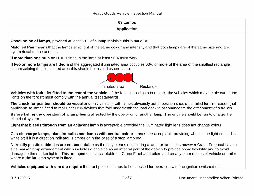
Heavy Goods Vehicle Inspection Manual
01/10/2015 3 of 7 Document Uncontrolled When Printed
63 Lamps Application
Obscuration of lamps, provided at least 50% of a lamp is visible this is not a RfF. Matched Pair means that the lamps emit light of the same colour and intensity and that both lamps are of the same size and are symmetrical to one another. If more than one bulb or LED is fitted in the lamp at least 50% must work. If two or more lamps are fitted and the aggregated illuminated area occupies 60% or more of the area of the smallest rectangle circumscribing the illuminated area this should be treated as one lamp.
Illuminated area Rectangle Vehicles with fork lifts fitted to the rear of the vehicle. If the fork lift has lights to replace the vehicles which may be obscured, the lights on the fork lift must comply with the annual test standards. The check for position should be visual and only vehicles with lamps obviously out of position should be failed for this reason (not applicable to lamps fitted to rear under-run devices that fold underneath the load deck to accommodate the attachment of a trailer). Before failing the operation of a lamp being affected by the operation of another lamp. The engine should be run to charge the electrical system. Light that bleeds through from an adjacent lamp is acceptable provided the illuminated light lens does not change colour. Gas discharge lamps, blue tint bulbs and lamps with neutral colour lenses are acceptable providing when lit the light emitted is white or; if it is a direction indicator is amber or in the case of a stop lamp red. Normally plastic cable ties are not acceptable as the only means of securing a lamp or lamp lens however Crane Fruehauf have a side marker lamp arrangement which includes a cable tie as an integral part of the design to provide some flexibility and to avoid damage to the marker lights. This arrangement is acceptable on Crane Fruehauf trailers and on any other makes of vehicle or trailer where a similar lamp system is fitted. Vehicles equipped with dim dip require the front position lamps to be checked for operation with the ignition switched off.

Heavy Goods Vehicle Inspection Manual
01/01/2013 4 of 7 Document Uncontrolled When Printed
63 Lamps Application
A summary of the main requirements for each type of lamp is shown below.
TYPE DATE OF FIRST USE (MANUFACTURE FOR
TRAILERS)
POSITION COLOUR MAX DISTANCE
FROM SIDE (MM) MAX HEIGHT
(MM) MINIMUM HEIGHT
(MM)
Front Position Lamps
Motor Vehicles From April 1986 400 1500 or if impracticable
2100 - White or yellow if in a
headlamp which shows yellow light Before April 1986 510 2300 -
Trailers From October 1985 150 1500 or if impracticable
2100 - White
Before October 1985 510 2300 -
Front End Outline Marker Lamp
Motor Vehicles From April 1991 400 - The top of the lamp
shall be no lower than the top of the windscreen
White
Trailers From October 1990 400 -
As high as possible with regard to the
lateral position, and the use for which the vehicle is constructed
Dipped Beam Headlamp From 1972 (refer to
Lighting regulations for earlier vehicles)
400 Being a matched
pair 1200 500 White or Yellow
Main Beam Headlamp
From 1931 - - White or Yellow
Rear Position Lamps
Motor Vehicles From April 1986 400 1500 or if impracticable
2100 350
Red Trailers From October 1985
Motor Vehicles Before April 1986 800 2100 -
Trailers Before October 1985

Heavy Goods Vehicle Inspection Manual
01/10/2014 5 of 7 Document Uncontrolled When Printed
63 Lamps Application
A summary of the main requirements for each type of lamp (continued).
Rear End Outline Marker Lamps
Motor Vehicles From April 1991
400 -
As high as possible with regard to the
lateral position, and the use for which the vehicle is constructed
Red Trailers From October 1990
Stop Lamps From 1971 (refer to
Lighting regulations for earlier vehicles)
One on each side with a minimum
separation distance of 400mm
1500 or if impracticable 2100 350 Red
Rear Registration Plate Lamp All vehicles and trailers - - - White
Rear Fog Lamp Motor vehicles and trailers From April 1980
Where one lamp is fitted: On centre line or offside of vehicle.
1200 250 Red
Side Marker Lamps
Motor vehicles 1 April 1991 - 2300 - Amber or red if within 1m of the rear of the
vehicle.
Trailers 1 October 1990 - 2300 -
Amber or red if within 1m of the rear of the trailer or if fitted to a
trailer built before October 1990
exceeding 9.15m in length one side marker
lamp on each side, positioned
longitudinally such that no part of the light emitting surface is forward of, or more than 1530mm to the
rear of, the centre point of the overall length of the trailer. The lamp
may show a white light to the front and a red
light to the rear, or alternatively amber.

Heavy Goods Vehicle Inspection Manual
01/01/2013 6 of 7 Document Uncontrolled When Printed
63 Lamps Method of Inspection Reason for Failure
1. Check lamps for: a. presence and security of an obligatory lamp. b. correct illumination and function. c. presence of the lens, its visibility, security and condition. d. showing a light of the right colour. e. correct position. f. a steady light when lightly tapped by hand. g. not being affected by the operation of any other lamp.
2. Check the fog lamp (in addition to the above):
a. fog lamp has a tell tale light fitted, working and visible to the driver.
b. the number of rear fog lamps fitted. 3. Check the stop lamp (in addition to the above) for a steady red
light when the brakes are applied and goes out when the brakes are released.
1. For all lamps: *a. an obligatory lamp missing or insecure. *b. a lamp dim, due to dirt or internal deterioration, or not
working.
*c. a lens missing, obscured, insecure, or damaged so it is likely to fall apart.
*d. not showing a light of the right colour.
*e. incorrectly positioned. *f. flickers when lightly tapped by hand. *g. is affected by the operation of any other lamp.
2. Fog lamp:
a. tell-tale light not fitted, not working or cannot be seen by the driver.
b. more than two rear fog lamps are fitted.
*3. Stop lamp does not show a steady red light when the brakes are applied, or does not go out when the brakes are released.

Heavy Goods Vehicle Inspection Manual
20/03/2013 7 of 7 Document Uncontrolled When Printed
63 Lamps Method of Inspection Reason for Failure
4. Check a headlamp (in addition to the above) for:
a. forming part of a matched pair. b. being positioned symmetrically in relation to the other
lamp.
c. a lamp of a matched pair showing a light of the same intensity and colour as the other.
d. a main beam headlamp that can be switched off by the operation of one switch which at the same time leaves a pair of dipped beams.
e. a main beam warning light illuminates when main beam is selected and extinguishes when dipped beam is selected.
5. Check the rear registration plate lamp (in addition to the above) does not throw direct light to the rear
4. Headlamp:
a. not forming part of a matched pair. b. not positioned symmetrically in relation to the other lamp.
c. one of a matched pair does not show a light of the same intensity and colour as the other.
d. a main beam headlamp cannot be switched off by operating one switch which at the same time leaves a pair of dipped beams.
e. main beam warning lamp does not illuminate when main beam is selected and extinguish when dipped beam is selected.
5. A rear registration plate lamp throws direct light to the rear.
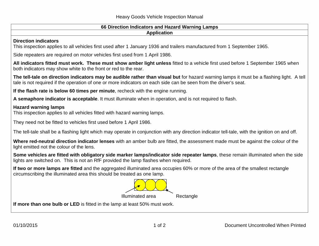
Heavy Goods Vehicle Inspection Manual
01/10/2015 1 of 2 Document Uncontrolled When Printed
66 Direction Indicators and Hazard Warning Lamps Application
Direction indicators This inspection applies to all vehicles first used after 1 January 1936 and trailers manufactured from 1 September 1965.
Side repeaters are required on motor vehicles first used from 1 April 1986. All indicators fitted must work. These must show amber light unless fitted to a vehicle first used before 1 September 1965 when both indicators may show white to the front or red to the rear.
The tell-tale on direction indicators may be audible rather than visual but for hazard warning lamps it must be a flashing light. A tell tale is not required if the operation of one or more indicators on each side can be seen from the driver’s seat.
If the flash rate is below 60 times per minute, recheck with the engine running. A semaphore indicator is acceptable. It must illuminate when in operation, and is not required to flash.
Hazard warning lamps This inspection applies to all vehicles fitted with hazard warning lamps. They need not be fitted to vehicles first used before 1 April 1986. The tell-tale shall be a flashing light which may operate in conjunction with any direction indicator tell-tale, with the ignition on and off. Where red-neutral direction indicator lenses with an amber bulb are fitted, the assessment made must be against the colour of the light emitted not the colour of the lens. Some vehicles are fitted with obligatory side marker lamps/indicator side repeater lamps, these remain illuminated when the side lights are switched on. This is not an RfF provided the lamp flashes when required. If two or more lamps are fitted and the aggregated illuminated area occupies 60% or more of the area of the smallest rectangle circumscribing the illuminated area this should be treated as one lamp.
Illuminated area Rectangle If more than one bulb or LED is fitted in the lamp at least 50% must work.

Heavy Goods Vehicle Inspection Manual
01/07/2013 2 of 2 Document Uncontrolled When Printed
66 Direction Indicators and Hazard Warning Lamps Method of Inspection Reason for Failure
1. Check direction indicators for:
a. presence, operation, operating on the correct side of a vehicle/trailer, their condition and are visible to the front and rear.
b. presence of a side repeater. c. the presence of the lens, its security and condition. d. flashing at between 60 to 120 times a minute.
e. a light of the right colour. f. presence of a tell-tale, its operation and can be
seen/heard by the driver.
g. the rate of flash and illumination is not affected by any other lamp.
h. the operation of a semaphore indicator.
2. Check hazard warning lamps for:
a. operation with the engine stopped and the ignition switched off and on.
b. all the direction indicator lamps operating simultaneously
when switched on by one switch.
c. presence of a tell-tale, its operation and it can be seen by the driver.
1. Direction indicator:
a. missing, inoperative, operating on the wrong side of a vehicle/trailer, dim or not visible either to the front or to the rear.
b. side repeater missing. c. lens missing, insecure or damaged so that it is likely to fall
apart. d. does not flash at between 60 to 120 times a minute. e. does not show a light of the right colour.
f. tell-tale not fitted, is inoperative or cannot be seen/heard
by the driver.
g. rate of flash or illumination is affected by any other lamp.
h. a semaphore indicator sticking. 2. Hazard warning lamp:
a. does not operate with the engine stopped and the ignition switched off and on.
b. all the direction indicator lamps do not operate
simultaneously when switched on by one switch.
c. tell-tale not fitted, is inoperative or cannot be seen by the driver.

Heavy Goods Vehicle Inspection Manual
01/01/2013 1 of 4 Document Uncontrolled When Printed
67 Aim of Headlamps Application
The headlamp aim criterion is applicable to all dipped beam headlamps. Headlamp beam converters fitted to right hand dipping headlamps which effectively mask/deflect the beam are acceptable provided that the pass criterion is met. Some vehicles may be fitted with an "in-cab" headlamp adjustment device. If the vehicle is presented for test unladen, the in cab headlamp adjustment device must be set relative to this condition. In all other cases this may be adjusted to enable both headlamps to meet the criteria, however both headlamps must comply with the requirements with the device set in one position. The headlamp control in the cab is allowed to be used to align the headlamps without failing the vehicle. Most modern vehicles are fitted with European headlamps. Dipped beam headlamps can be identified from the marking on the lamps. There will be a "C" shown above an "E" or "e" mark. Repairs must not be carried out during a test however; minor adjustments to the headlamp aim are acceptable. If the beam pattern is blurred due to condensation and does not show a distinctive cut-off point for the examiner to determine whether the alignment is correct this will be a failure under Reason for Failure 1. Some vehicles with complex headlamp systems (with the dipped beam and main beam having separate pockets) may be encountered. It is essential that the headlamp aim test equipment is aligned exactly on the centre of the dipped beam pocket. At this point it may not be possible to see a clearly defined headlamp pattern, in order to see the full beam pattern, it may be necessary to move the vehicle closer to the test equipment. Once this has been done, the beam pattern should be clearly visible on the aiming screen. When a full pattern can be seen, the normal assessment of headlamp aim should be followed.
The standards to be applied are shown above the beam patterns likely to be encountered on the following pages.

Heavy Goods Vehicle Inspection Manual
01/04/2015 2 of 4 Document Uncontrolled When Printed
67 Aim of Headlamps Method of Inspection Reason for Failure
Align the headlamp aim testing equipment to the vehicle in accordance with the manufacturer’s instructions.
European checked on Dipped Beam 1. In relation to the 0% Horizontal line, the beam horizontal cut-off line is not between the limits listed below.
Headlamp centres up to and including 850mm high Upper limit: All vehicles. 0.5% Lower limit: All vehicles 4.0% Headlamp centres over 850mm high Upper limit: All vehicles. 1.25% Lower limit: All vehicles 4.0% 2. The beam image contains a "Kick up" that is not visible on the
screen 3. White light shows in the zone formed by the 0% vertical and
0.5% horizontal lines

Heavy Goods Vehicle Inspection Manual
01/01/2013 3 of 4 Document Uncontrolled When Printed
67 Aim of Headlamps Method of Inspection Reason for Failure
British American Checked on Dipped Beam
Align the headlamp aim testing equipment to the vehicle in accordance with the manufacturer’s instructions.
4. In relation to the 0% Horizontal line, the upper edge of the “Hot Spot” is not between the limits listed below.
All headlamp heights
Upper limit: All vehicles. 0% Lower limit: All vehicles 4.0%
5. The right hand edge of the “Hot Spot” is to the right of the
vertical 0% line, or more than 2% to the left of it. 6. All - A Headlamp dips to the right. (See note in Applications).

Heavy Goods Vehicle Inspection Manual
01/01/2013 4 of 4 Document Uncontrolled When Printed
67 Aim of Headlamps Method of Inspection Reason for Failure
British American Checked on Main Beam
Align the headlamp aim testing equipment to the vehicle in accordance with the manufacturer’s instructions.
7. In relation to the 0% Horizontal line, the centre of the “Hot Spot” is not between the limits listed below.
Headlamp centres up to and including 850mm high Upper limit: All vehicles. 0% Lower limit: All vehicles. 2.0%
Headlamp centres over 850mm high
Upper limit: All vehicles. 0% Lower limit: All vehicles. 2.75%
8. In any case the centre of the “Hot Spot” is to the right of the
vertical 0% line or more than 2% to the left of it. 9. A Headlamp dips to the right. (See note in Applications).

Heavy Goods Vehicle Inspection Manual
01/01/2013 1 of 7 Document Uncontrolled When Printed
71 Service Brake Performance Application
This inspection applies to all vehicles and trailers. To avoid damage to the vehicle or the equipment, no tyre must be obviously underinflated. In the case of vehicle and trailer combinations, each unit of the combination is considered separately. In this section of the manual, the term "drum" includes "discs". Attention must be paid to Hybrid Electric Vehicles (HEVs). Due to the nature of the control systems some vehicles can not be tested on the Roller Brake Tester and must receive a decelerometer brake test. Some vehicles have a regenerative braking system connected to the service brake system. If the regenerative system cannot be disconnected from the service brake, a decelerometer brake test is required. If the regenerative system can be disconnected and the vehicle control system allows a roller brake test this must be carried out. If you are in any doubt whether a vehicle can be roller brake tested and if the presenter does not know, contact T.S.S. Swansea. Brake testing HEVs, with a regenerative brake system must be appropriately charged (appropriately in this context means the red warning light showing there is a defect is not illuminated). Vehicles that require decelerometer testing are: Mercedes Axor Bluetec Hybrid. Vehicles that can be tested on the brake rollers are: Mitsubishi Canter – Transmission must be in neutral. Smiths Electical – Light vehicles ignition needs to be turned on and neutral selected.
Heavy vehicles, High voltage system needs to be on and neutral selected.

Heavy Goods Vehicle Inspection Manual
01/01/2013 2 of 7 Document Uncontrolled When Printed
71 Service Brake Performance Application
Before failing a vehicle for binding, examiners should be aware that drag at a wheel may be recorded which is not necessarily due to brakes, but may be due to transmission drag, or by the deformation of the tyres on the rollers, which on a fully laden 10,000 kg axle could be as much as 250kg. A recorded bind in excess of 4% of the measured axle weight should be considered a Reason for Failure. Brake effort fluctuation of more than 70% of the higher brake effort recorded at a steady pedal pressure is a Reason for Failure. For ease of calculation if the higher brake effort divided by the lower brake effort is greater than 3.3 this is a Reason for Failure. The highest reading obtained should be recorded when the brake force from any one wheel is fluctuating in a regular manner between two readings, (e.g.1850kg should be recorded where the needle reading was fluctuating between 1750kg and 1850kg). Using the maximum recorded forces for each wheel on an axle, check that the braking effort from any wheel is 70% or more of the effort of the other wheel on the same axle. When wheels lock, this Reason for Failure will not apply if both the wheels lock, or if one wheel locks and the braking effort of the locked wheel is less than that of the other. Little or no brake effort recorded at any road wheel should be considered a Reason for Failure if less than 5% of the measured axle weight is not attained. In the case of a motor vehicle the Brake data cards should be used wherever possible. Locked Wheels If more than half the number of wheels lock, the specified brake effort can be considered to be met. On a motor vehicle where not more than half the wheels lock, where available the allowances contained in any data card information must be taken into account. Wheels on the verge of locking are not acceptable, they must fully lock. Load Simulation To obtain a higher reading for brake effort than is possible with the vehicle as presented, use a load simulator to apply a load whenever practicable, or have the vehicle loaded. Certain three axle tractor units can only be satisfactorily brake tested when presented coupled to a laden semi-trailer. Where this is the case stations must insist that the combination is suitably loaded so that axle weights are higher than 65% of the design axle weight.

Heavy Goods Vehicle Inspection Manual
01/01/2013 3 of 7 Document Uncontrolled When Printed
71 Service Brake Performance Application
Vehicles fitted with Load Sensing valves Where possible the load simulator should be used to apply a load, so that the valve operates. Where it is not possible to apply a load, the driver may be allowed to temporarily disconnect the valve linkage, or otherwise by-pass the valve, immediately before the brake test, to allow the required braking force to be achieved. The driver must ensure that the valve has been restored to its proper working condition before the vehicle leaves the Testing Station. Failure to do so may break the law.
Deceleration Test If the vehicle cannot be roller brake tested, or for any other reason a decelerometer test is required, proceed as MOI.
Double Drive Rear Axle - Interposing Differential Before carrying out a brake test on a vehicle fitted with a double drive rear axle it will be necessary to establish whether an interposing differential is fitted or not. A check can be carried out by using the R.B.T. in the following manner:
• Instruct the driver to release all brakes and ensure the gear lever is in the neutral position. • Start the nearside roller in the forward direction and observe the offside wheel, if this turns in the reverse direction no
interposing differential is fitted and the brake test will need to be carried out as explained in paragraphs # # below. • If the running of one wheel has no effect on the other on the same axle, then the test can be conducted as for a single drive
axle. ## If no interposing differential is fitted carry out the test as follows :
• Place chocks at front and rear of the wheels of the front axle. • Press and hold on N/S forward and O/S reverse button simultaneously, the wheel under test must turn forward and the
opposite wheel on the same axle must turn in the reverse direction. • Carry out the brake test as described above.
Do not run the rollers any longer than necessary to obtain an accurate reading. Release both buttons together:
• Change direction of rollers and carry out test on the O/S wheel brake. • Repeat the above procedure for all brake systems at this axle. • Move the vehicle forward and carry out the same procedure for the second driving axle.
A transmission brake fitted to a vehicle of this type can not be tested on a roller brake tester.

Heavy Goods Vehicle Inspection Manual
01/04/2015 4 of 7 Document Uncontrolled When Printed
71 Service Brake Performance Application
Drop off of brake effort If drop off of brake effort is noted during the roller brake test, first confirm that it is drop off and not simply due to the driver releasing the brake pedal or brake effort fluctuation. If drop off is confirmed it will be appropriate to consider a failure under Inspection Manual item 59. Vehicles with full power hydraulic braking systems If necessary to confirm compliance with Test Item 34 for vehicles with full powered hydraulic braking systems the following additional tests should be made: • Position the vehicle so that each axle in turn is located on the roller brake tester. • With the engine stopped, deplete the brake pressure by repeated application of the service brake pedal until commencement of
operation of the low pressure warning device. • With the roller brake test machine driving the wheels of each axle in turn;
a. apply the service brake slowly and check for first indications of braking effort. Release brake immediately. Re-apply the brake, check for a second time for indication of braking effort, and release immediately.
b. repeat test sequence for each axle in turn. Skeletal vehicles with an empty body fitted should be treated as unladen. For vehicles with Hydrostatic drives if the brake performance is not met on the brake rollers, perform a decelerometer test before making a decision on the pass fail requirements. Prior to roller brake testing any vehicle with hydrostatic drive and a transmission parking brake it may be necessary when the wheels are in the roller set to select the vehicles mode which disengages/bypasses the hydrostatic drive. Engaging this mode will prevent any hydrostatic retardation showing as excessive levels of bind. With some DTP numbers the roller brake tester may request you check for brake effort drop off, you need to establish whether the vehicle has air over hydraulic brakes, if it has do the drop off test, if the system is full air ignore the request for the drop off test. Ensure that the air suspension on tag/pusher axles that may have been jacked up are inflated should there be a problem achieving the brake efficiency for these axles (the inflation should only be done under supervision of station staff). Switching the ignition off on vehicles equipped with EBS is to be taken as the same as vehicles having their LSV disconnected. Tri axle trailers equipped with Knorr Bremse EBS/ABS should be driven to the RBT and not allowed to switch the ignition off while stationary on the brake rollers, if this circumstance occurs the following procedure must be followed:
A. Make sure the ignition is switched off, B. apply the parking brake, C. apply the footbrake, D. switch the ignition on, E. start the engine, F. release the foot brake and parking brake and carry out a full brake test on all axles using the appropriate unladen or laden tri axle trailer criteria.

Heavy Goods Vehicle Inspection Manual
01/01/2013 5 of 7 Document Uncontrolled When Printed
71 Service Brake Performance Application
Vehicles and Trailers with Electronic Braking System (EBS) 1. Testing Vehicles with EBS Braking Systems Vehicles with EBS that have load sensing on the front axle. If the minimum front axle brake figure is not achieved because the load sensing valve is regulated by the load imposed on the rear axle/s, re-test the front axle brakes in the following manner.
a) Build up the air reservoirs and stop the engine. b) Switch the engine off to deactivate the load-sensing valve. c) Carry out the brake performance test.
Switching the ignition off on a vehicle with EBS has the effect of by passing the load-sensing valve. 2. Testing Trailers With WABCO Trailer EBS (Electronic Braking System) How to recognise EBS. • No ABS warning lamp on the headboard. • With the ignition on, definitive solenoid clicks from the trailer on each application of the footbrake should be heard. • Plate with the heading "WABCO Trailer EBS" on the front of the trailer and a pictogram showing an X through LSV and ABS. • ISO 7638 electrical connector fitted in addition to the electrical connector for the lights. • Last digit of the DTp Reference number is an ‘8’. The brake computer has not been programmed to accept an 8 so this must be
replaced with 7 as the last digit. When presented, the tractor unit must be compatible with the trailer and have a warning lamp to indicate that trailer ABS is working (this may be a combined ABS/EBS warning light). If presented with a compatible EBS tractor unit, if the red line is dropped, the brakes may not come on. To apply the brakes disconnect the ISO 7638 electrical connection. Ensure that the handbrake is applied on the tractor unit before disconnecting the red line and that safe working practices are followed.
Irrespective of whether the trailer is laden or unladen, before commencing the brake test, the EBS Processor must be conditioned (not to be used for Knorr bremse ABS/EBS equipped trailers see note on previous page) this is done by:
Brake Testing
a) Putting the first axle of the trailer in the RBT. b) Switch off the engine/ignition and ensure no brake is applied. c) Restart engine. d) Continue the brake test as normal. This procedure only needs to be carried out once. The system will reset when the trailer is
driven at a speed greater than 7 KMH. Failure to do this will stop the Load Sensing Valve working, i.e. a full pressure brake reading on every application.

Heavy Goods Vehicle Inspection Manual
01/01/2013 6 of 7 Document Uncontrolled When Printed
71 Service Brake Performance Application
DGVW = Design Gross Vehicle Weight. DTAW = Design Total Axle(s) Weight.
SERVICE BRAKE EFFICIENCY REQUIREMENTS
Motor Vehicles 2 Axle Rigid vehicle first
used before 1 January 1968 and with no manufacturer’s
plate
Rigid vehicle with more than 2 axles or any articulated tractor first used before 1 January 1968 and
with no manufacturer’s plate
Any other vehicle
Specified Efficiency 45% DGVW 40% DGVW 50% DGVW
Semitrailers and centre axle draw-bar
trailers
Manufactured before 1 January 1968 with GVW
6100 kg or more
Manufactured before 1 January 1968 with GVW less than 6100 kg
Manufactured from 1 January 1968 to
30 September 1982
Manufactured from 1 October 1982
Specified Efficiency 35% DTAW 32% DTAW 40% DTAW 45% DTAW
Full drawbar trailers Manufactured before 1 January 1968
Manufactured from 1 January 1968 to 30 September 1982
Manufactured from 1 October 1982
Specified Efficiency 40% DGVW 50% DGVW 45% DGVW

Heavy Goods Vehicle Inspection Manual
01/10/2015 7 of 7 Document Uncontrolled When Printed
71 Service Brake Performance Method of Inspection Reason for Failure
1. Roller Brake Test Machines Operating With a Computer Controlled Brake Test Follow the sequence of instructions as displayed and prompted on screen. On completion of the test a result sheet is printed indicating the test result.
2. All Roller Brake Test Machines a. check no brake on any wheel is binding. b. apply brake slowly and check for abnormal time lag in
operation of the brake on any wheel. c. on a (vehicle) steered axle with the service brake applied at a
steady pedal pressure, check there is no indication of brake effort fluctuations regularly with each revolution of the road wheel.
The ovality check does not apply to trailers.
d. continue to apply the brake until the road wheel is just at the point of slip relative to the rollers, or until the service brake is fully applied, whichever occurs first. Note the maximum recorded brake effort.
3. Decelerometer test.
Set the decelerometer on the vehicle in accordance with the instrument manufacturer’s instructions. At a speed of approximately 20mph, have the service brake applied, note the reading on the decelerometer and whether the vehicle deviates from a straight line.
1. Roller Brake Test Machines Operating With a Computer Controlled Brake Test
As computer prompt instructions (unless overruled). 2. All Roller Brake Test Machines a. a brake on any wheel binding. b. brake mechanism on any wheel sticking, indicated by an
abnormal time lag before, an increased reading is obtained. c. with service brake applied at a steady pedal pressure, the
indication of brake effort fluctuates regularly with each revolution of the road wheel, on a steered axle, so much that the ovality of any brake drum is obvious. A fluctuation of recorded reading in excess of 70%, between highest and lowest indicated readings is to be considered a Reason for Failure.
d. With the service brake fully applied: *i there is little or no brake effort at any wheel. *ii braking effort from any wheel on an axle is less than
70% of the brake effort from another wheel on the same axle.
*iii the specified brake effort is not met.
*3. Decelerometer test. The braking efficiency recorded by decelerometer is below the specified efficiency for the vehicle under test, or the vehicle deviates appreciably from a straight line.

Heavy Goods Vehicle Inspection Manual
01/10/2015 1 of 2 Document Uncontrolled When Printed
72 Secondary Brake Performance Application
This inspection applies to all motor vehicles where the designated secondary brake operates independently of the service brake. The notes relating to Electrical and Hybrid Electrical Vehicles under Inspection 71 also apply to this inspection particularly where the designated secondary brake is the parking brake, refer to these notes before deciding what type of brake test should be performed. To avoid damage to the vehicle or the equipment, no tyre must be obviously under inflated. There may be occasions where the specified brake effort is met but, if the brake effort from any wheel on an axle is one third or less than the brake effort from another wheel on the same axle, it may be necessary to consider Reason for Failure 1a, 1b or 5a of Inspection 59. The notes relating to Locked Wheels and Load Simulation under Inspection 71 also apply to this inspection.
DGVW = Design Gross Vehicle Weight.
SECONDARY BRAKE EFFICIENCY REQUIREMENTS
Motor Vehicles 2 Axle Rigid vehicle first used before 1 January 1968 and with no manufacturer’s plate
Rigid vehicle with more than 2 axles or any articulated tractor first used before 1 January 1968 and with no manufacturer’s plate
Any other vehicle
Specified Efficiency
20% DGVW
15% DGVW
25% DGVW

Heavy Goods Vehicle Inspection Manual
01/10/2015 2 of 2 Document Uncontrolled When Printed
72 Secondary Brake Performance Method of Inspection Reason for Failure
1. Roller Brake Test Machines Operating With a Computer Controlled Brake Test Follow the sequence of instructions as displayed and prompted on screen. On completion of the test a result sheet is printed indicating the test result.
2. All Roller Brake Test Machines For each road wheel in turn apply the secondary brake until the:
a. road wheel is just at the point of slip relative to the rollers, or
b. the secondary brake is fully applied, whichever occurs first.
Note the maximum braking effort indicated from the brake of each road wheel.
1. Roller Brake Test Machines Operating With a Computer Controlled Brake Test As computer prompt instructions (unless overruled.)
2. All Roller Brake Test Machines With the secondary brake fully applied:
a. there is little or no braking effort at any wheel equipped with a brake operated by the secondary brake system.
*b the specified brake effort is not met.

Heavy Goods Vehicle Inspection Manual
01/01/2013 1 of 3 Document Uncontrolled When Printed
73 Parking Brake Performance Application
This inspection applies to all vehicles and trailers. The notes relating to Electrical and Hybrid Electrical Vehicles under Inspection 71 also apply to this inspection, refer to these notes before deciding what type of brake test should be performed.
To avoid damage to the vehicle or the equipment, no tyre must be obviously under-inflated, and the brake rollers should not be continuously applied.
It is necessary to use an applied brake method of testing as described in the MOI, except for vehicles with transmission parking brakes, or if the R.B.T. is not capable of carrying out an applied test. In these cases it is necessary to use the ALTERNATIVE method as described in the MOI.
There may be occasions where the specified brake effort is met but, if the brake effort from any wheel on an axle is one third or less than the brake effort from another wheel on the same axle, it may be necessary to consider Reason for Failure 1a, 1b or 5a of Inspection 59 depending on the operation controls of the system (e.g. cable, rods, air or hydraulic). The notes relating to Locked Wheels and Load Simulation under Inspection 71 also apply to this inspection.
If a vehicle has had its DGTW reduced, the DTp number may not reflect this new weight. It may be necessary to calculate the park brake performance for the new DGTW at 12% or the DGVW at 16% whichever is the greater.
If a trailer has more than one parking brake fitted, each park brake must meet the minimum standard of efficiency.
Where a trailer has been permanently attached to a towing vehicle, it is still mandatory to have a park brake on the trailer.

Heavy Goods Vehicle Inspection Manual
01/01/2013 2 of 3 Document Uncontrolled When Printed
73 Parking Brake Performance Application
DGVW = Design Gross Vehicle Weight. DGTW = Design Gross Train Weight. *Type Approved - Manufactured from 1 October 1982 and first used from 1 April 1983 and has been issued with a Type Approval Certificate of Conformity, a Ministers Approval Certificate or a Type Approval Certificate issued by an EU member state.
PARKING BRAKE EFFICIENCY REQUIREMENTS
Motor Vehicles Any vehicle first used before 1 January 1968
Any vehicle first used from 1 January 1968 apart from a Type Approved articulated tractor or drawing vehicle
A Type Approved* articulated tractor or drawing vehicle
Specified Efficiency – 16% DGVW 16% DGVW 12% DGTW
Semi-trailers and Draw-bar trailers
Manufactured before 1 January 1968
Any other trailer
Specified Efficiency – 16% DGVW

Heavy Goods Vehicle Inspection Manual
01/01/2013 3 of 3 Document Uncontrolled When Printed
73 Parking Brake Performance Method of Inspection Reason for Failure
1. Roller Brake Test Machines Operating With a Computer Controlled Brake Test Follow the sequence of instructions as displayed and prompted on screen. On completion of the test a result sheet is printed indicating the test result.
2. Applied Brake Test on a Roller Brake Tester Apply the parking brake fully and release any power assistance. The service brake may be used at this stage in setting the park brake. Start each brake machine roller in turn and note the maximum braking effort indicated for each wheel in turn.
3. Alternative method With the roller brake test machine driving each road wheel in turn, apply the parking brake slowly until each road wheel is just at the point of slip relative to the rollers, or until the parking brake is fully applied, whichever occurs first. Note the braking maximum effort indicated from the brake of each road wheel.
Transmission Parking Brakes. If the parking brake is a transmission brake, all wheels on the same axle braked by it must be driven by the roller test machine at the same time.
4. Transmission Parking Brakes Roller Brake Test. With the roller brake machine driving both road wheels together, instruct the driver to apply the transmission brake as slowly as possible, constantly keeping the release button depressed, until any road wheel is just at the point of slip relative to the rollers, then release the brake quickly. Note the braking effort indicated from the brake of each wheel.
1. Roller Brake Test Machines Operating With a Computer Controlled Brake Test
As computer prompt instructions (unless overruled). 2. Applied Brake Test on a Roller Brake Tester With the parking brake fully applied:
a. there is little or no braking effort at any wheel equipped with a brake operated by the parking brake system.
*b. the specified brake effort is not met.
3. Alternative method With the parking brake fully applied:
a. there is little or no braking effort on any wheel equipped with a parking brake, or
*b. the specified brake effort is not met. 4. Transmission Parking Brakes Roller Brake Test. With the transmission parking brake full applied:
a. there is little or no brake effort, or *b. the specified brake effort is not met.

Heavy Goods Vehicle Inspection Manual
01/01/2013 1 of 1 Document Uncontrolled When Printed
74 Other Dangerous Defects Application
This applies to all vehicles and trailers. Whilst this manual attempts to be comprehensive and cover all reasons for failure which could be dangerous it is inevitable that due to changes in design, or other reasons, from time to time dangerous defects may be found which are not described in any of the reasons for failure in the other items in this manual. If a defect of this type is found, which is such that the use of the vehicle on the road would involve a danger of injury to any person, this would justify a failure under this item. In addition it would be appropriate to issue an Immediate Prohibition for a defect of this nature. It is not intended that this item should be used as a matter of routine but only for exceptional cases. If a failure is recorded under this item full details must be shown on the test card and a copy should be sent to Testing and Support Services so that any trends can be noted and amendments made to the manual if necessary.
Method of Inspection Reason for Failure
**1. A defect not described elsewhere in the manual such that the use of the vehicle or trailer on the road would involve a danger of injury to any person.