
HFC-227ea is clean, efficient, environmentally acceptable, and leaves no residue, thus minimizing...
33
Page 1 of 33 V20140828 HFC-227ea Engineered System Design, Installation & Maintenance Manual Foreword This manual provides instructions and information on the Design, Installation and maintenance of the FSL CG 2 HFC-227ea Engineered System, referred to hereinafter as the CG 2 System. Systems shall be designed, installed and maintained in accordance with this manual and the internationally recognised standards: NFPA 2001, Standard on clean agent fire extinguishing systems ISO 14520, Gaseous fire-extinguishing systems. EN 15004-1, Fixed fire fighting system – Gas extinguishing systems Note: Any reference to ISO 14520 shall be read as ISO 14520 or EN 15004. (The part and clause references are correct for ISO 14520) The manual must be read in conjunction with the International Standards because the requirements from the standards are excluded from the text. CG 2 systems must be designed, installed, commissioned and maintained by qualified and competent personnel who have the relevant training and experience. Systems are Total Flooding and suitable for buildings, plant or other structures See ISO 14520-1 1.0 Any questions, queries and suggested improvements should be brought to the attention of FSL. This design manual does NOT include the use of the CG 2 system for local application or explosion suppression systems and marine or aviation use. All are Engineered Total Flooding systems which must be designed using the FSL CG 2 Design calculation program. Pre-engineered systems are NOT covered. FSL strives to continually improve its products and systems and this manual may not reflect the latest products. The pressure vessel containing the fire extinguishing agent is generally referred to as a cylinder or container. This manual generally uses the word container. FSL CG2 227 Technical Manual FINAL
Transcript of HFC-227ea is clean, efficient, environmentally acceptable, and leaves no residue, thus minimizing...

Page 1 of 33 V20140828
HFC-227eaEngineered System Design, Installation & Maintenance Manual
ForewordThis manual provides instructions and information on the Design, Installation and maintenance of the FSLCG2 HFC-227ea Engineered System, referred to hereinafter as the CG2 System.
Systems shall be designed, installed and maintained in accordance with this manual and the internationallyrecognised standards:
NFPA 2001, Standard on clean agent fire extinguishing systemsISO 14520, Gaseous fire-extinguishing systems.EN 15004-1, Fixed fire fighting system – Gas extinguishing systems
Note: Any reference to ISO 14520 shall be read as ISO 14520 or EN 15004. (The part and clause referencesare correct for ISO 14520)
The manual must be read in conjunction with the International Standards because the requirements fromthe standards are excluded from the text.
CG2 systems must be designed, installed, commissioned and maintained by qualified and competentpersonnel who have the relevant training and experience. Systems are Total Flooding and suitable forbuildings, plant or other structures See ISO 14520-1 1.0
Any questions, queries and suggested improvements should be brought to the attention of FSL.
This design manual does NOT include the use of the CG2 system for local application or explosionsuppression systems and marine or aviation use. All are Engineered Total Flooding systems which must bedesigned using the FSL CG2 Design calculation program. Pre-engineered systems are NOT covered.
FSL strives to continually improve its products and systems and this manual may not reflect the latestproducts.
The pressure vessel containing the fire extinguishing agent is generally referred to as a cylinder or container.This manual generally uses the word container.
FSL CG2 227 Technical Manual FINAL
Page 2 of 33 V20140828
Table of ContentsForeword ............................................................................................................................................................... 1Introduction .......................................................................................................................................................... 3Approvals .............................................................................................................................................................. 3Equipment ............................................................................................................................................................. 4
HFC-227ea Physical Properties ....................................................................................................................... 4Safety Considerations ...................................................................................................................................... 5
Equipment Description ......................................................................................................................................... 6Cylinder/Container Assembly.......................................................................................................................... 6Outlet Adaptors (Part no. NF2333050 NF2349050) ...................................................................................... 7Discharge flexible hoses (Part no. NF2333500 NF2349550) ......................................................................... 9Discharge Check Valves and Manifolds (Check Valves NF46000**) ............................................................. 9Outlet Spacer (Part No. NF234980) ................................................................................................................ 9Discharge nozzles (Part no. NF2515** to NF2550**) ................................................................................. 10Discharge Valve Actuation ............................................................................................................................ 10Pilot pressure actuation ................................................................................................................................ 10Slave actuation............................................................................................................................................... 10Pilot Hose ....................................................................................................................................................... 10Signs and Labels ............................................................................................................................................. 11
System design ..................................................................................................................................................... 12System design procedure: ............................................................................................................................. 12Agent Requirement ...................................................................................................................................... 12Number of Containers .................................................................................................................................. 14Container Location ....................................................................................................................................... 15Personnel safety check ................................................................................................................................. 15Nozzle Determination ................................................................................................................................... 15Piping configuration ..................................................................................................................................... 16System hydraulic calculations ...................................................................................................................... 17Venting Considerations ................................................................................................................................ 18Leakage from the protected space .............................................................................................................. 18Control and release of the system ................................................................................................................ 18
Installation........................................................................................................................................................... 19Safety Procedure ........................................................................................................................................... 19Containers/Cylinders and valve connections ............................................................................................... 19Discharge Hoses ............................................................................................................................................. 20Discharge Check Valves and Manifolds ........................................................................................................ 20Discharge Piping ............................................................................................................................................ 22Hangers and Bracing ...................................................................................................................................... 23Discharge Nozzles .......................................................................................................................................... 23Discharge Valve Pressure Gauge, Pressure Switch ...................................................................................... 23Assembly of the discharge valve actuators .................................................................................................. 24Pneumatic Actuator Connection Hoses (Part no. NF271560) ..................................................................... 27Actuation Options .......................................................................................................................................... 27Discharge pressure switch NF280210A ........................................................................................................ 28
Installation Check List .............................................................................................Error! Bookmark not defined.Verification and Test........................................................................................................................................... 28
General ........................................................................................................................................................... 30Piping .............................................................................................................................................................. 30Nozzles ........................................................................................................................................................... 30Electrical ......................................................................................................................................................... 31Integrated Solenoid fitted to the discharge valve. ..................................................................................... 31Separate Solenoid Actuator NF2601* ......................................................................................................... 31
Maintenance ....................................................................................................................................................... 32Temperature/Pressure HFC 227ea .................................................................................................................... 33
Page 3 of 33 V20140828
Introduction
The system provides a Total Flooding fire suppression system in accordance with NFPA 2001 or ISO 14520
HFC-227ea may be used in the protection of the following types of facilities:Data processingProcess control roomsTelecommunications facilitiesHigh value assets
HFC-227ea is NOT suitable for:Certain chemicals or mixtures of chemicals, such as cellulose nitrate and gunpowder, that arecapable of rapid oxidation in the absence of airReactive metals such as lithium, sodium, potassium, magnesium, titanium, zirconium, uranium,and plutoniumMetal hydridesChemicals capable of undergoing automatic thermal decomposition, such as certain organicperoxides or hydrazine
Fire detection and Controls:This manual covers the design and installation of the fire suppression/extinguishing system not the firedetection, actuation, or control requirements. These are important aspects to ensure the correct operationof the extinguishing system and must be completed by skilled and competent personnel to appropriateinternational standards e.g. ISO14520, NFPA2001, BS 5839, BS 7273.
These systems require fast detection and discharge to minimise the fire damage and the extinguishantdecomposition. Do not delay the extinguishant discharge longer than is necessary to evacuate theprotected space. Any delay will allow the fire to increase in size, producing more products of combustionand result in more decomposition products during the extinguishing process.
Approvals
This manual has been approved by the Loss Prevention Certification Board for the Design of FSL’s CG2 CleanAgent Engineered Systems using approved components and equipment. The Approval was obtained againstLPS 1230.
Full details of the Scope, Qualifications/limitations can be found on the BRE Red Book live web site.www.redbooklive.com/
Approved System design concentrations.
ProductName
Risk DesignConcentration**
FSL CG2 Class A (Standard) 7.9%FSL CG2 Class A (Cables) 8.5%FSL CG2 Class B 9.0%
** The design concentrations include a safety factor of 1.3 over the extinguishing concentration.Note: Inerting is excluded from the scope of the LPCB approval
Page 4 of 33 V20140828
Equipment
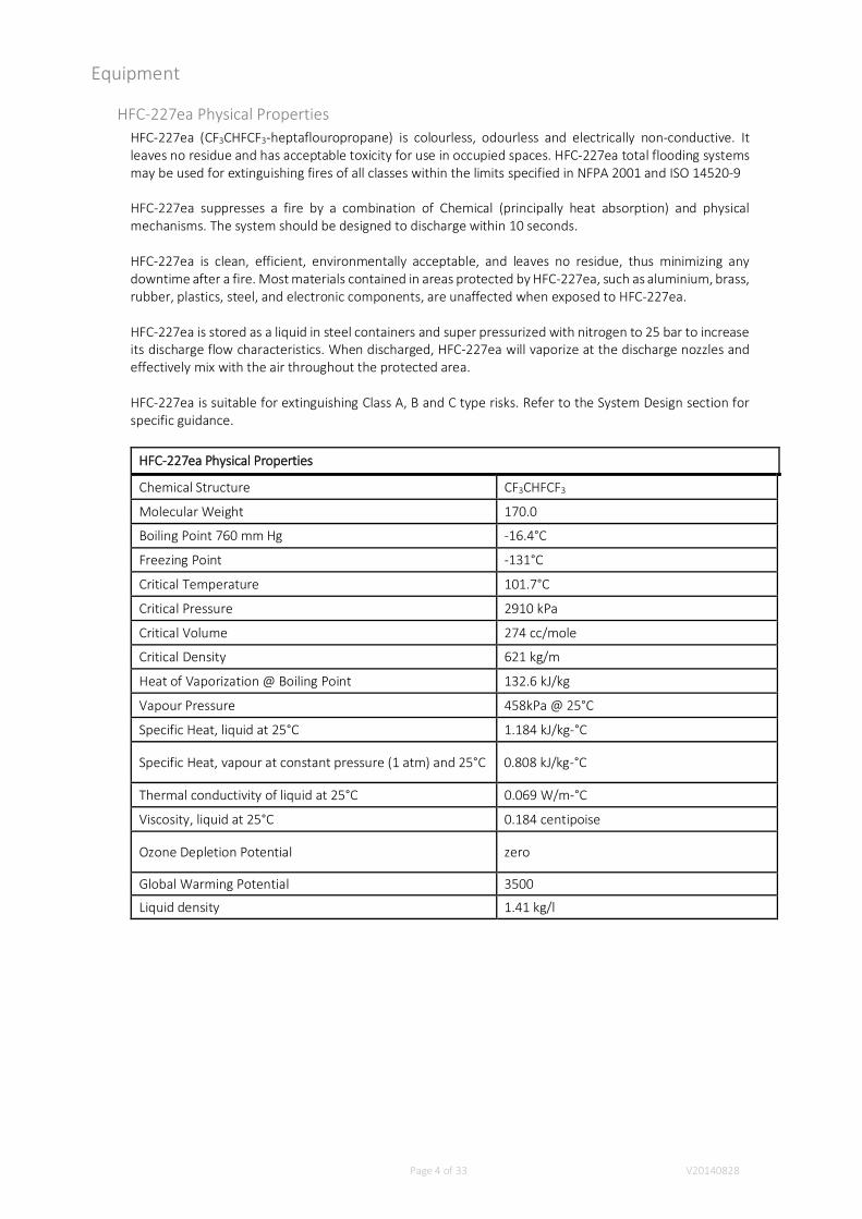
HFC-227ea Physical PropertiesHFC-227ea (CF3CHFCF3-heptaflouropropane) is colourless, odourless and electrically non-conductive. Itleaves no residue and has acceptable toxicity for use in occupied spaces. HFC-227ea total flooding systemsmay be used for extinguishing fires of all classes within the limits specified in NFPA 2001 and ISO 14520-9
HFC-227ea suppresses a fire by a combination of Chemical (principally heat absorption) and physicalmechanisms. The system should be designed to discharge within 10 seconds.
HFC-227ea is clean, efficient, environmentally acceptable, and leaves no residue, thus minimizing anydowntime after a fire. Most materials contained in areas protected by HFC-227ea, such as aluminium, brass,rubber, plastics, steel, and electronic components, are unaffected when exposed to HFC-227ea.
HFC-227ea is stored as a liquid in steel containers and super pressurized with nitrogen to 25 bar to increaseits discharge flow characteristics. When discharged, HFC-227ea will vaporize at the discharge nozzles andeffectively mix with the air throughout the protected area.
HFC-227ea is suitable for extinguishing Class A, B and C type risks. Refer to the System Design section forspecific guidance.
HFC-227ea Physical Properties
Chemical Structure CF3CHFCF3
Molecular Weight 170.0
Boiling Point 760 mm Hg -16.4°C
Freezing Point -131°C
Critical Temperature 101.7°C
Critical Pressure 2910 kPa
Critical Volume 274 cc/mole
Critical Density 621 kg/m
Heat of Vaporization @ Boiling Point 132.6 kJ/kg
Vapour Pressure 458kPa @ 25°C
Specific Heat, liquid at 25°C 1.184 kJ/kg-°C
Specific Heat, vapour at constant pressure (1 atm) and 25°C 0.808 kJ/kg-°C
Thermal conductivity of liquid at 25°C 0.069 W/m-°C
Viscosity, liquid at 25°C 0.184 centipoise
Ozone Depletion Potential zero
Global Warming Potential 3500
Liquid density 1.41 kg/l
Page 5 of 33 V20140828
Safety ConsiderationsHFC-227ea has acceptable toxicity for use in occupied spaces as a total flooding agent. Refer to the NFPA2001 and ISO 14520-9 or National guidelines for specific exposure limitations and discharge controls.
The Material Safety Data Sheet (MSDS) covering HFC-227ea should be read and understood prior to workingwith the agent. Safety items such as personnel training, evacuation plans and fire drills should beconsidered.
Refer to ISO 14520-9 5 for current Toxicity levels. The No observed adverse effect (NOAEL) level is 9% byvolume and the Lowest observed adverse effect level (LOAEL) is 10.5%. For egress times from the protectedspace Annex G of ISO 14520-1 gives guidance.
We advise that all personnel are evacuated from the protected space prior to actuating the system to avoidthem breathing the fires products of combustion. During the extinguishing process some decompositionproducts are produced, the amount of which is proportional to the fire size. Very low concentrations will bean irritant which will be a disincentive to enter the protected space and thus protect the health of personnel.The products of combustion and decomposition products can be acidic and corrosive to the contents of theprotected space and should not be allowed to remain in the protected space. These products must bepromptly and thoroughly ventilated from the protected space prior to allowing re-entry.
The gases may have migrated to neighbouring areas. Ensure that these areas are thoroughly ventilated.
Agent Decomposition ConsiderationAn unchecked fire will produce ‘products of combustion’ and at the seat of the fire only, HFC-227ea willdecompose to extinguish the fire. These decomposition products are hazardous to health and should notbe breathed.
On very hot surfaces (e.g., furnaces and ovens) HFC-227ea could decompose (typically above 600°C). Theeffects of HFC-227ea decomposition on equipment should be considered in hazards with high ambienttemperatures.
Consideration should be given for providing adequate means of venting the protected area after adischarge.
VisibilityThe discharge of HFC-227ea into a space may cause a reduction in visibility due to the moisture in the aircondensing for a brief period. This will in disappear in seconds as the agent warms to the surroundings.
ChillingThe HFC-227ea is stored as a liquid and vaporises at the nozzle. Any direct contact with the issuing agentwill cause rapid cooling and possibly frostbite. Do not mount any delicate equipment adjacent to thedischarge nozzles.
NoiseThe discharge may result in some noise from the nozzle.

Page 6 of 33 V20140828
Agent Decomposition ConsiderationAn unchecked fire will produce ‘products of combustion’ and at the seat of the fire only, HFC-227ea willdecompose to extinguish the fire. These decomposition products are hazardous to health and should notbe breathed.
On very hot surfaces (e.g., furnaces and ovens) HFC-227ea could decompose. The effects of HFC-227eadecomposition on equipment should be considered in hazards with high ambient temperatures.
Consideration should be given for providing adequate means of venting the protected area after adischarge.
HFC-227ea agent storage containersThese are heavy and must be handled with care and the correct handling facilities. To prevent accidentaldischarge or damage to the equipment when not fully restrained (in the installed location) all actuatorsmust be disconnected or removed where possible, all anti-recoil devices must be in place and transportcaps fitted.
Equipment Description
HFC-227ea systems are intended to be used to suppress fires involving equipment or specific hazards. It isvery effective where an inert, electrically non-conductive agent is required, or when clean-up of otheragents presents a problem.
Each HFC-227ea system is specifically designed to accommodate the individual demands of the areas to beprotected. The wide range of configurations of the components provides the flexibility necessary for thiscustom design.
An Engineered system requires that hydraulic flow calculations are undertaken to size the pipe work anddischarge nozzles. Only the FSL program shall be used. Normal system design shall be at 21°C.
Cylinder/Container AssemblyHFC-227ea is stored in specially designed cylinder assemblies. Cylinders are available in various sizes. Allcylinders are super pressurized with dry nitrogen to a pressure of 25 bar at 21°C. Each cylinder is equippedwith an identification nameplate indicating the quantity of HFC-227ea, pressurisation level and fillingstation.
Containers/cylinders shall be constructed to National Standards and be independently certified for use inthe region of use. Note that the 25 bar system will require different container working pressures. Acceptablestandards for use in:
Europe are EN 13322-1 Transportable cylinders – welded, EN 1964-2 transportable cylinders –seamless, Transportable Pressure equipment Directive (TPED 99/36 EC) and the carriage ofdangerous goods by road regulations (ADR).USA is DOT 4BW500India IS7285-2
Each cylinder assembly has a rigid dip/siphon tube and is designed for mounting in a vertical position withthe valve uppermost only.
Cylinder: The steel cylinders/containers are manufactured to the requirements various National Standardsappropriate with their country of use. The fill range shall be 0.4 to 1.12 kg/litre. Note that themaximum fill range should only be used in conjunction with short pipe runs.Do not leave the containers where they can be exposed to rapid changes of temperature from cold tohot because the internal pressure can rise significantly.
Dip Tube: The dip/siphon tube extends from the discharge valve to a closely controlled distance from the baseof the container. (The minimum distance between the flat inlet to the dip tube and the base of thecontainer, taking into account the worst case tolerance of the dip tube and container internal depthshall be 50% of the bore diameter of the dip tube). Maximum gap shall be the dip tube bore. Thisensures a full liquid discharge of agent. Dip tubes are screwed into the valve and retained with athread sealant.
Page 7 of 33 V20140828
1 0 6S W
4 6S W
23
5
72
B
B
49
65
99
,5
G1
/8"
2 , 1 2 5 "-1 6 U N
3 "-1 2 U N
35
92
8 0
8 9
21
/2"-
12
UN
4 2M x 1 , 5
P ilot port
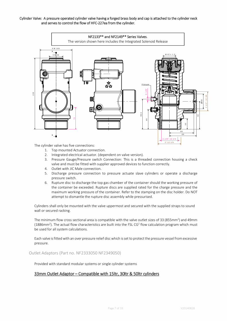
Cylinder Valve: A pressure operated cylinder valve having a forged brass body and cap is attached to the cylinder neckand serves to control the flow of HFC-227ea from the cylinder.
The cylinder valve has five connections:1. Top mounted Actuator connection.2. Integrated electrical actuator. (dependent on valve version).3. Pressure Gauge/Pressure switch Connection: This is a threaded connection housing a check
valve and must be fitted with supplier approved devices to function correctly.4. Outlet with JIC Male connection.5. Discharge pressure connection to pressure actuate slave cylinders or operate a discharge
pressure switch.6. Rupture disc to discharge the top gas chamber of the container should the working pressure of
the container be exceeded. Rupture discs are supplied rated for the charge pressure and themaximum working pressure of the container. Refer to the stamping on the disc holder. Do NOTattempt to dismantle the rupture disc assembly while pressurised.
Cylinders shall only be mounted with the valve uppermost and secured with the supplied straps to soundwall or secured racking.
The minimum flow cross sectional area is compatible with the valve outlet sizes of 33 (855mm2) and 49mm(1886mm2). The actual flow characteristics are built into the FSL CG2 flow calculation program which mustbe used for all system calculations.
Each valve is fitted with an over pressure relief disc which is set to protect the pressure vessel from excessivepressure.
Outlet Adaptors (Part no. NF2333050 NF2349050)
Provided with standard modular systems or single cylinder systems
33mm Outlet Adaptor – Compatible with 15ltr, 30ltr & 50ltr cylinders
NF2133** and NF2149** Series Valves.The version shown here includes the Integrated Solenoid Release

Page 8 of 33 V20140828
Outlet Size = 1 ½” BSPP (Female)
49mm Outlet Adaptor – Compatible with 80ltr, 120ltr, 150ltr & 180ltr cylinders
Outlet Size = 2” BSPP (Female)
(Demonstration picture only)
Page 9 of 33 V20140828
Discharge flexible hoses (Part no. NF2333500 NF2349550)Only the hoses supplied shall be used these have an appropriate pressure and flow rating.
If multiple cylinders are banked together for discharge into a common manifold then:All cylinders must be of the same size and fill and pressurisationAll flexible hoses must be fitted with a Check/Non return valve.
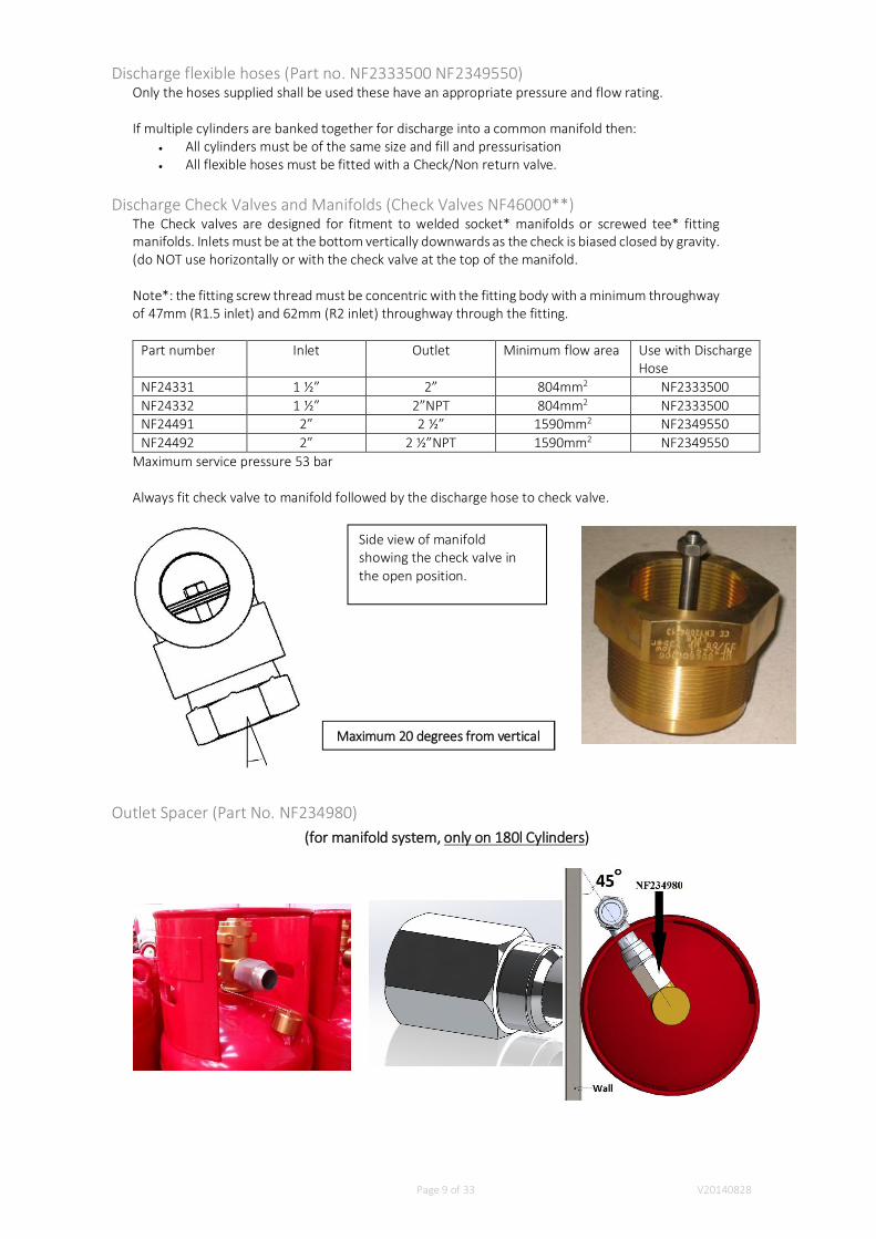
Discharge Check Valves and Manifolds (Check Valves NF46000**)The Check valves are designed for fitment to welded socket* manifolds or screwed tee* fittingmanifolds. Inlets must be at the bottom vertically downwards as the check is biased closed by gravity.(do NOT use horizontally or with the check valve at the top of the manifold.
Note*: the fitting screw thread must be concentric with the fitting body with a minimum throughwayof 47mm (R1.5 inlet) and 62mm (R2 inlet) throughway through the fitting.
Part number Inlet Outlet Minimum flow area Use with DischargeHose
NF24331 1 ½” 2” 804mm2 NF2333500NF24332 1 ½” 2”NPT 804mm2 NF2333500NF24491 2” 2 ½” 1590mm2 NF2349550NF24492 2” 2 ½”NPT 1590mm2 NF2349550
Maximum service pressure 53 bar
Always fit check valve to manifold followed by the discharge hose to check valve.
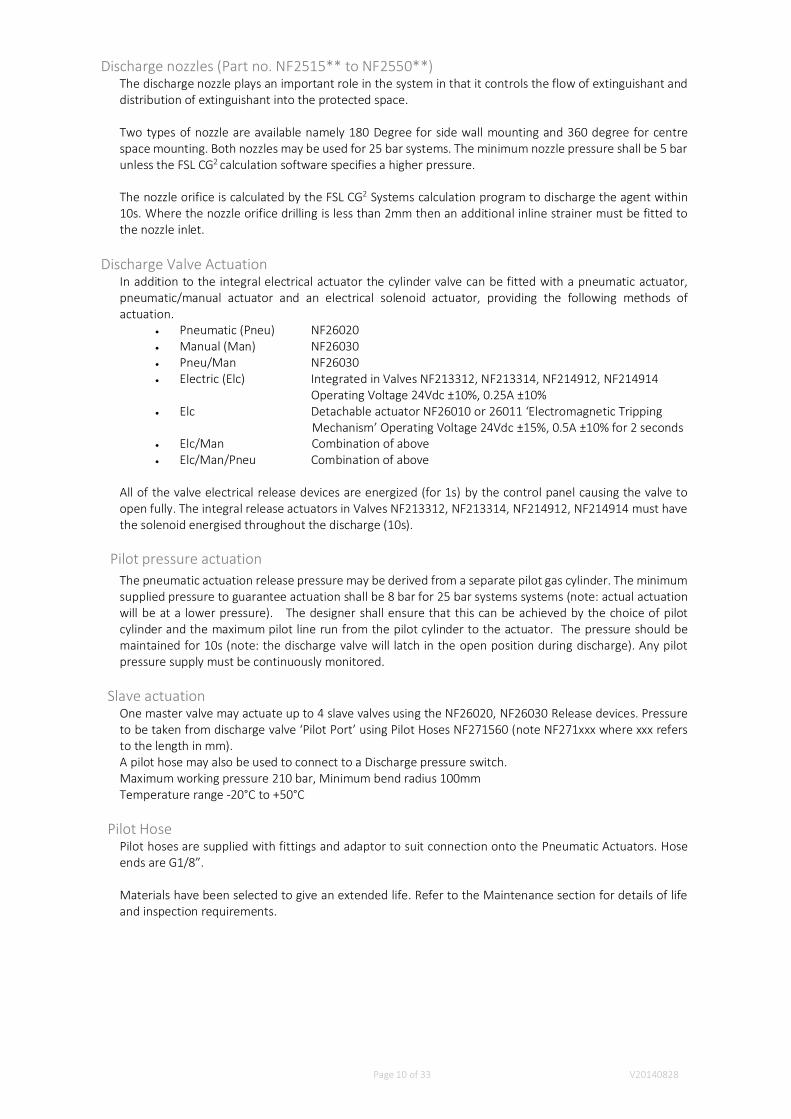
Outlet Spacer (Part No. NF234980)(for manifold system, only on 180l Cylinders)
Maximum 20 degrees from vertical
Side view of manifoldshowing the check valve inthe open position.
Page 10 of 33 V20140828
Discharge nozzles (Part no. NF2515** to NF2550**)The discharge nozzle plays an important role in the system in that it controls the flow of extinguishant anddistribution of extinguishant into the protected space.
Two types of nozzle are available namely 180 Degree for side wall mounting and 360 degree for centrespace mounting. Both nozzles may be used for 25 bar systems. The minimum nozzle pressure shall be 5 barunless the FSL CG2 calculation software specifies a higher pressure.
The nozzle orifice is calculated by the FSL CG2 Systems calculation program to discharge the agent within10s. Where the nozzle orifice drilling is less than 2mm then an additional inline strainer must be fitted tothe nozzle inlet.
Discharge Valve ActuationIn addition to the integral electrical actuator the cylinder valve can be fitted with a pneumatic actuator,pneumatic/manual actuator and an electrical solenoid actuator, providing the following methods ofactuation.
Pneumatic (Pneu) NF26020Manual (Man) NF26030Pneu/Man NF26030Electric (Elc) Integrated in Valves NF213312, NF213314, NF214912, NF214914
Operating Voltage 24Vdc ±10%, 0.25A ±10%Elc Detachable actuator NF26010 or 26011 ‘Electromagnetic Tripping Mechanism’ Operating Voltage 24Vdc ±15%, 0.5A ±10% for 2 secondsElc/Man Combination of aboveElc/Man/Pneu Combination of above
All of the valve electrical release devices are energized (for 1s) by the control panel causing the valve toopen fully. The integral release actuators in Valves NF213312, NF213314, NF214912, NF214914 must havethe solenoid energised throughout the discharge (10s).
Pilot pressure actuationThe pneumatic actuation release pressure may be derived from a separate pilot gas cylinder. The minimumsupplied pressure to guarantee actuation shall be 8 bar for 25 bar systems systems (note: actual actuationwill be at a lower pressure). The designer shall ensure that this can be achieved by the choice of pilotcylinder and the maximum pilot line run from the pilot cylinder to the actuator. The pressure should bemaintained for 10s (note: the discharge valve will latch in the open position during discharge). Any pilotpressure supply must be continuously monitored.
Slave actuationOne master valve may actuate up to 4 slave valves using the NF26020, NF26030 Release devices. Pressureto be taken from discharge valve ‘Pilot Port’ using Pilot Hoses NF271560 (note NF271xxx where xxx refersto the length in mm).A pilot hose may also be used to connect to a Discharge pressure switch.Maximum working pressure 210 bar, Minimum bend radius 100mmTemperature range -20°C to +50°C
Pilot HosePilot hoses are supplied with fittings and adaptor to suit connection onto the Pneumatic Actuators. Hoseends are G1/8”.
Materials have been selected to give an extended life. Refer to the Maintenance section for details of lifeand inspection requirements.

Page 11 of 33 V20140828
Signs and LabelsAll entrances to the protected space shall be identified as entering a space protected by HFC-227ea. Theform of the label shall follow the guidance in NFPA 2001 and ISO 14520-1. This will contain a warning toevacuate the protected space upon the first fire alarm.
Within the protected space the following information shall be displayed:Identity of agentDesign VolumeType of riskNOAEL/LOAEL levelsType of actuation (manual/automatic)
Page 12 of 33 V20140828
System designThe information contained in this section covers the design of engineered systems. The designer must befully conversant with the relevant design codes i.e. NFPA 2001 or ISO 14520-1
The design of the system consists of the selection and proper placement of the following equipment:Container(s)Mounting bracket(s)Nozzle(s)Pipe and fittingsControl panel(s)DetectionOptional accessories
The selection and placement of the alarm and control devices shall conform to relevant InternationalStandards.
System design procedure:
Agent RequirementComplete a risk assessment and survey of the space to confirm:
Sealing integrity (to prevent the loss of agent after discharge). The only way to ensure that thespace is sufficiently sealed to retain the concentration for the minimum hold time is to undertakea room integrity test. In general the protected space must be completely sealed. This manualdoes NOT cover extended discharge and all spaces must be sealed sufficiently to hold theconcentration from the initial discharge.Fire resistance of the enclosureDimensions. Ensure that the difference between the Gross and the Net volume are taken intoconsideration. Follow ISO 14520-1 In general Ceiling and Floor voids should be treated asseparate spaces.Use and occupancyHazards to be protected. Hazards to be protected e.g. Class A, B and C. Refer to ISO 14520-1 7.1and the LPCB listing for guidance on extinguishing concentrations.
Formula for calculating the quantity of agent is given in ISO 14520-9 Table 3 (Specific vapourvolumes against temperature, formula and pre-calculation tables) and the FSL CG2 Calculationprogram which should be run for every system automates this process and provides a record.Always calculate the quantity of agent based on the minimum temperature of the protectedspace.The Table, formula and calculation program takes into account temperature, specific volumeof vapour and altitude (see ISO 14520-1 7.7 for the altitude correction factor).The formula and tables take into account the loss of gas through openings during thedischarge.The maximum discharge time shall be 10s. No pre-calculation tables are given here (see ISO14520-9 Table 3).Should a single agent supply be available to protect more than one risk then the quantityshould be sufficient for the largest risk. Take account of the achieved concentration in thesmallest risk.The calculation program takes into account the friction loss through the pipes, fittings andcomponents and changes in elevation. Al the information is contained within the CG2
Calculation program and this shall be the only method of designing and calculating a dischargepipe work system.
As per ISO 14520-1 7.8 the minimum hold time for the concentration shall be 10 minutes. Thisshould be longer for deep seated fires where more than 10 minutes is require for the ignitionsource to cool. Annex E of ISO 14520-1 gives formulae for calculating the minimum hold timeand refer to the vapour density given in the specific agent data. If the pressure relief vents arenot self-closing these free flow areas must be taken into consideration.Temperature. Temperature range of the hardware is -20°C to + 50°C and -10°C to +100°C for theprotected space.Ventilation. All forced ventilation that is not 100% recycling the protected space air must bestopped prior to discharge.Altitude See ISO 14520-9 7.7 -1,000m to +4,500mEnsure that no other gaseous extinguishing system is installed.
Page 13 of 33 V20140828
The agent will extinguish Class C Fires but consider the build-up of flammable gas which couldproduce an explosion hazard.Inerting should be considered with care because the discharging extinguishant could produce astatic charge and ignite a flammable atmosphere. Refer to ISO 14520-9 7.5.2 for guidance onconcentrations. Generally higher concentrations are required for inerting.Doors should open outwards and be fitted with self-closers to facilitate evacuation in the eventof a fire.Consider the environmental impact of the system selected. Use the system which gives thelowest environmental impact against fire fighting effectiveness, speed of extinguishment, safety,weight and economics.Use the concentrations derived from the approval fire testing stated here in the manual todetermine the quantity of agent. The concentration should be based on the highestconcentration required for the fuel present in the risk area. Note the differences between NFPA2001 or ISO 14520-9 standards on concentration requirements. For highly volatile fuel theinerting concentrations may be necessary. Where the design concentrations for extinguishingand inerting are not given follow the advice given on how to determine these.Ensure that the insurer, fire authority, building control authority and clients representativeagrees to the design parameters.A full discharge test should not be carried out because of the environmental impact of theextinguishing agent. Should there be any doubt about the viability of the system then alternativearrangements should be made.
All of the above information and design parameters together with workings drawing must be submitted tothe client’s representation for acceptance and approval. See ISO 14520-9 7.2
Page 14 of 33 V20140828
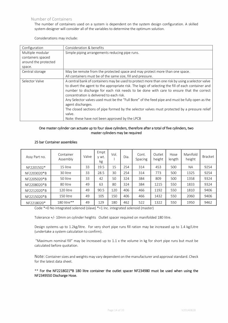
Number of ContainersThe number of containers used on a system is dependent on the system design configuration. A skilledsystem designer will consider all of the variables to determine the optimum solution.
Considerations may include:
Configuration Consideration & benefitsMultiple modularcontainers spacedaround the protectedspace.
Simple piping arrangements reducing pipe runs.
Central storage May be remote from the protected space and may protect more than one space.All containers must be of the same size, fill and pressure.
Selector Valve A central bank of containers may be used to protect more than one risk by using a selector valveto divert the agent to the appropriate risk. The logic of selecting the fill of each container andnumber to discharge for each risk needs to be done with care to ensure that the correctconcentration is delivered to each risk.Any Selector valves used must be the “Full Bore” of the feed pipe and must be fully open as theagent discharges.The closed sections of pipe formed by the selector valves must protected by a pressure reliefvalve.Note: these have not been approved by the LPCB
One master cylinder can actuate up to four slave cylinders, therefore after a total of five cylinders, twomaster cylinders may be required
25 bar Container assemblies
Assy Part no.ContainerAssembly
ValveEmpty wt.
kg
Vol.l Dia.
Cont.Spacing
Outletheight
Hoselength
Manifoldheight
Bracket
NF2201502* 15 litre 33 19.5 15 254 314 453 500 NA 9254
NF2203020*B 30 litre 33 28.5 30 254 314 773 500 1325 9254
NF2205020*B 50 litre 33 42 50 324 384 809 500 1358 9324
NF2208020*B 80 litre 49 63 80 324 384 1215 550 1833 9324
NF2212020*B 120 litre 49 90.5 120 406 466 1192 550 1810 9406
NF2215020*B 150 litre 49 105 150 406 466 1432 550 2060 9406
NF2218020* 180 litre** 49 129 180 462 522 1322 550 1950 9462Code *=0 No integrated solenoid (slave) *=1 Inc. integrated solenoid (master)
Tolerance +/- 10mm on cylinder heights Outlet spacer required on manifolded 180 litre.
Design systems up to 1.2kg/litre. For very short pipe runs fill ration may be increased up to 1.4 kg/Litre(undertake a system calculation to confirm).
“Maximum nominal fill” may be increased up to 1.1 x the volume in kg for short pipe runs but must becalculated before quotation.
Note: Container sizes and weights may vary dependent on the manufacturer and approval standard. Checkfor the latest data sheet.
** For the NF2218021*B 180 litre container the outlet spacer NF234980 must be used when using theNF2349550 Discharge Hose.
Page 15 of 33 V20140828
Container LocationContainer mounting considerations include:
Floor loadingAccess for installation, service and mechanical release of the system.Tampering, obstruction and damage.Environment (hot/cold, dirty, corrosive. Normally containers will be mounted with or adjacentto the protected space). Refer to the storage and use limitations.Distance from the protected space.Mount in a protected environment away from direct sunlight, corrosive atmospheres and awayfrom wind and rain.Protect from exposure to mechanical damage and fire.Temperature to be within -20°C to 50°CThe container storage should be ventilated.Always secure the containers to a wall or frame with the C shaped container straps provided.Only containers with the same fill and pressure may be connected to the same dischargemanifold.
Container can only be mounted vertically with the valve uppermost.
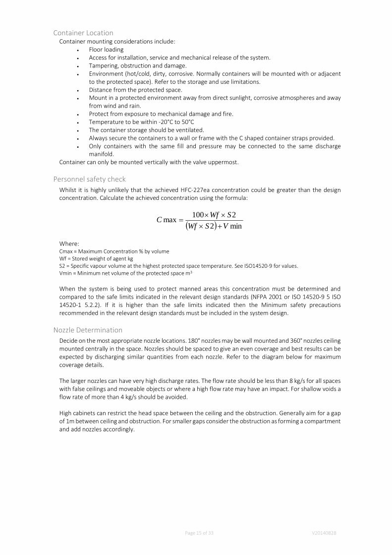
Personnel safety checkWhilst it is highly unlikely that the achieved HFC-227ea concentration could be greater than the designconcentration. Calculate the achieved concentration using the formula:
min22100max
VSWfSWfC
Where:Cmax = Maximum Concentration % by volumeWf = Stored weight of agent kgS2 = Specific vapour volume at the highest protected space temperature. See ISO14520-9 for values.Vmin = Minimum net volume of the protected space m3
When the system is being used to protect manned areas this concentration must be determined andcompared to the safe limits indicated in the relevant design standards (NFPA 2001 or ISO 14520-9 5 ISO14520-1 5.2.2). If it is higher than the safe limits indicated then the Minimum safety precautionsrecommended in the relevant design standards must be included in the system design.
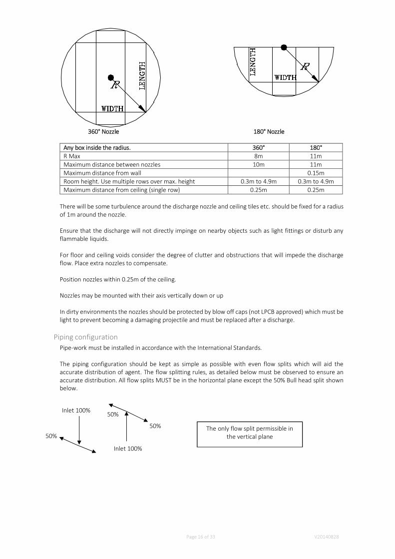
Nozzle DeterminationDecide on the most appropriate nozzle locations. 180° nozzles may be wall mounted and 360° nozzles ceilingmounted centrally in the space. Nozzles should be spaced to give an even coverage and best results can beexpected by discharging similar quantities from each nozzle. Refer to the diagram below for maximumcoverage details.
The larger nozzles can have very high discharge rates. The flow rate should be less than 8 kg/s for all spaceswith false ceilings and moveable objects or where a high flow rate may have an impact. For shallow voids aflow rate of more than 4 kg/s should be avoided.
High cabinets can restrict the head space between the ceiling and the obstruction. Generally aim for a gapof 1m between ceiling and obstruction. For smaller gaps consider the obstruction as forming a compartmentand add nozzles accordingly.
Page 16 of 33 V20140828
360° Nozzle 180° Nozzle
Any box inside the radius. 360° 180°R Max 8m 11mMaximum distance between nozzles 10m 11mMaximum distance from wall 0.15mRoom height. Use multiple rows over max. height 0.3m to 4.9m 0.3m to 4.9mMaximum distance from ceiling (single row) 0.25m 0.25m
There will be some turbulence around the discharge nozzle and ceiling tiles etc. should be fixed for a radiusof 1m around the nozzle.
Ensure that the discharge will not directly impinge on nearby objects such as light fittings or disturb anyflammable liquids.
For floor and ceiling voids consider the degree of clutter and obstructions that will impede the dischargeflow. Place extra nozzles to compensate.
Position nozzles within 0.25m of the ceiling.
Nozzles may be mounted with their axis vertically down or up
In dirty environments the nozzles should be protected by blow off caps (not LPCB approved) which must belight to prevent becoming a damaging projectile and must be replaced after a discharge.
Piping configurationPipe-work must be installed in accordance with the International Standards.
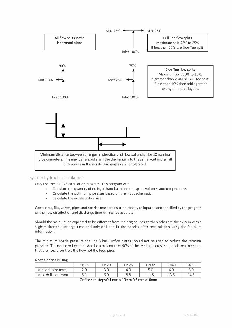
The piping configuration should be kept as simple as possible with even flow splits which will aid theaccurate distribution of agent. The flow splitting rules, as detailed below must be observed to ensure anaccurate distribution. All flow splits MUST be in the horizontal plane except the 50% Bull head split shownbelow.
50%
Inlet 100%
50% The only flow split permissible inthe vertical plane
Inlet 100%
50%
Page 17 of 33 V20140828
System hydraulic calculationsOnly use the FSL CG2 calculation program. This program will:
Calculate the quantity of extinguishant based on the space volumes and temperature.Calculate the optimum pipe sizes based on the input schematic.Calculate the nozzle orifice size.
Containers, fills, valves, pipes and nozzles must be installed exactly as input to and specified by the programor the flow distribution and discharge time will not be accurate.
Should the ‘as built’ be expected to be different from the original design then calculate the system with aslightly shorter discharge time and only drill and fit the nozzles after recalculation using the ‘as built’information.
The minimum nozzle pressure shall be 3 bar. Orifice plates should not be used to reduce the terminalpressure. The nozzle orifice area shall be a maximum of 90% of the feed pipe cross sectional area to ensurethat the nozzle controls the flow not the feed pipe.
Nozzle orifice drillingDN15 DN20 DN25 DN32 DN40 DN50
Min. drill size (mm) 2.0 3.0 4.0 5.0 6.0 8.0Max. drill size (mm) 5.1 6.9 8.8 11.5 13.5 14.5
Orifice size steps 0.1 mm < 10mm 0.5 mm >10mm
Min. 25%Max 75%
90%
Min. 10%
75%
Max 25%
Inlet 100%
Inlet 100% Inlet 100%
All flow splits in thehorizontal plane
Minimum distance between changes in direction and flow splits shall be 10 nominalpipe diameters. This may be relaxed are if the discharge is to the same void and small
differences in the nozzle discharges can be tolerated.
Bull Tee flow splitsMaximum split 75% to 25%
If less than 25% use Side Tee split.
Side Tee flow splitsMaximum split 90% to 10%.
If greater than 25% use Bull Tee split.If less than 10% then add agent or
change the pipe layout.

Page 18 of 33 V20140828
Venting ConsiderationsVenting of an enclosure may be necessary to relieve the under pressure due to the chilling of the air withinthe space and the following over pressure due to the extra volume being added to the space. The FSL CG2
calculation program will calculate the minimum free vent area based on the maximum pressure that theprotected space can withstand. Refer to the buildings structural engineer.
The protected space structure including the windows needs to be of adequate strength to withstand theseunder and over pressures.
The rule of thumb from the BSRIA document is 0.04m2 per 100m3. The actual value necessary can becalculated from the results of a Room integrity test where the actual room leakage and the strength of theprotected space can be taken into account.
*BSRIA, “Fire Extinguishing Systems, A guide to their integration with other building services”.www.bsria.co.uk
Leakage from the protected spaceAfter discharge the HFC-227ea must be retained for a sufficient period of time to allow the cooling of theignition source to prevent re-ignition. Refer to NFPA 2001 & ISO 14520-1 for guidance on the period.
To ensure that the retention time is achieved a room integrity test must be carried out in accordance withthe standards.
Control and release of the systemRefer to ISO 14520-1 6.4 for guidance. Where an automatic system is used then there must also be a manualrelease adjacent to the exit from the protected space.
National requirements must be followed for fire detection and controls. Suitable standards are BS 5839, BS7273, BS 6266
The release and delays permitted are dependent on the type of occupancy see ISO 14520-1 5.2. ForOccupied Spaces rules are given for concentration levels against the use of Time delays, Automatic/manualswitch and Lock-off device. Separate requirements are given for ‘normally unoccupied areas’ and‘unoccupied areas’.
Reference to ISO 14520-1 and BS 5839, 7273, 6266 for:Manual ControlAlarmsHold switchesTime delays

Page 19 of 33 V20140828
Installation
Safety ProcedureTo ensure the safety of personnel carrying out the installation and to prevent any accidental discharge ofthe container contents the steps below must be followed in order,
1. All containers must have;Shipping Cap fitted to the Actuator port of the valveAnti-Recoil cap fitted to valve outletActuators NOT fitted
2. Fix containers to mounting bracket3. Fix discharge pipe work complete with all nozzles and fit flexible hose to pipe work4. When containers are connected to the pipework all open ends of the pipework must be capped. At
least one cap in each network should have a small hole to indicate a discharge and vent the pipework.
5. Fit discharge hose to container6. Test actuators 'off' the container7. Reset actuators and fit to valve once commissioning is complete
Containers/Cylinders and valve connectionsThe HFC-227ea cylinder is pressurized to 25 and must be handled carefully.
The discharge valve is constructed of heavy forged brass, it can be damaged if dropped or mishandled.Discharge of an unsecured and disconnected cylinder could be extremely dangerous and may result in injuryor death, and/or damage to property.
Under normal conditions, the discharge valve cannot be discharged without having the various actuatorsattached. Never connect the actuators or have the solenoid pilot valve wired to the system’s electricalcontrols until the cylinder has been properly secured in the cylinder rack and the discharge connectionfittings connected to the system piping.
The anti-recoil cap should remain in place until removal is necessary to complete the connection of thevalve to the system piping.
Rupture discDO NOTremove.
Discharge pressure switchand pilot pressure portG1/8”
Contents pressuregauge/switch. 2 portsM10 special.
Page 20 of 33 V20140828
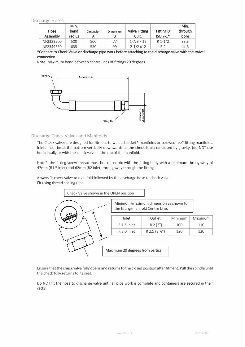
Discharge Hoses
HoseAssembly
Min.bendradius
DimensionA
DimensionB
Valve FittingC JIC
Fitting DISO 7-1*
Min.through
boreNF2333500 500 500 77 1-7/8 x 12 R 1-1/2 33.3NF2349550 635 550 99 2-1/2 x12 R 2 44.5
*Connect to Check Valve or discharge pipe work before attaching to the discharge valve with the swivelconnection.Note: Maximum bend between centre lines of fittings 20 degrees
Discharge Check Valves and ManifoldsThe Check valves are designed for fitment to welded socket* manifolds or screwed tee* fitting manifolds.Inlets must be at the bottom vertically downwards as the check is biased closed by gravity. (do NOT usehorizontally or with the check valve at the top of the manifold.
Note*: the fitting screw thread must be concentric with the fitting body with a minimum throughway of47mm (R1.5 inlet) and 62mm (R2 inlet) throughway through the fitting.
Always fit check valve to manifold followed by the discharge hose to check valve.Fit using thread sealing tape.
Ensure that the check valve fully opens and returns to the closed position after fitment. Pull the spindle untilthe check fully returns to its seat.
Do NOT fit the hose to discharge valve until all pipe work is complete and containers are secured in theirracks.
Inlet Outlet Minimum Maximum
R 1.5 inlet R 2 (2”) 100 110
R 2.0 inlet R 2.5 (2 ½”) 120 130
Maximum 20 degrees from vertical
Minimum/maximum dimension as shown tothe fitting/manifold Centre Line.
Check Valve shown in the OPEN position

Page 21 of 33 V20140828
Manifold arrangement[Note: Manifold size to be determined by VdS flow calculation]
Arrangement for 15ltr, 30ltr & 50ltr cylinders
Arrangement for 80ltr, 120ltr 150 ltr & 180ltr cylinders
Please refer to FSL Container datasheet for spacing lengths
Page 22 of 33 V20140828
Discharge PipingOnly discharge piping as specified in NFPA 2001 or ISO14520-1 shall be used while taking into account thesystem pressure and any potentially closed sections (between selector valves if fitted) and nationalregulations. All closed sections of pipe work shall be protected by a relief valve (Relief valves are not LPCBapproved).
Piping must be non-combustible and be able to withstand the protected pressures during discharge. The 25bar systems will develop different pressures namely 34 and 53bar respectively at 50 degC. Suitablestandards for use in Europe are EN 10241 2000 Pipe fittings and EN 10255 2004 Tubes.
In corrosive environments the pipe work shall be protected. In general all steel pipe work should begalvanised or zinc plated.
Follow the guidance in the international standards and local regulations on protecting the system and pipework from mechanical damage, the effects of fire, earthing (see ISO 14520-1 5.5) and electrical clearance(see ISO 14520-1 5.4), marking of pipe work and the competency of the installer. Do not install pipe workwhere it could be subjected to mechanical damage or the effects of a fire.
All pipe size reductions must be made with reducing fittings, concentric reducers, and reducing couplings.
All pipes must be adequately fixed as dictated by the standards. Particular attention must be paid to thebracing of all piping changes in direction and nozzles.
Manifolds and cylinders shall be firmly fixed to take all of the thrusts during a system discharge.
Screwed pipe and fittings should be clean cut with full length threads. Joints should be made with pipesealing tape or compound ensuring that the first 2 threads are not covered. This will ensure that no tape orcompound enters the pipe work.
Welded joints must permit full flow. Mitre weld fittings are not acceptable.
All pipe work must be free from deformities and ridges that can impede the flow and all burrs and sharpedges must be removed.
Each pipe section shall be cleaned internally after preparation and before assembly by means of swabbing,utilizing a suitable non-flammable cleaner. The pipe network shall be free of particulate matter and oilresidue before installation.
Only install the pipe work as shown on the installation drawing and ensure that all flow splits are horizontaland the distance between changes in direction and flow splits are maintained. (See Design section).
No changes to the pipe work layout are permitted without the authority of the system designer. Anychanges in lengths, pipe diameter and number of fittings will have a significant impact on the flowcalculations.
All pipe sizes, flow rates and pressure drops shall be calculated using the FSL CG2 calculation program. Thistakes into consideration pipe work and fitting friction pressure losses and changes in elevation as well asthe minimum and maximum flow rate to ensure turbulent flow. Refer to the following table for an estimateof these.
Pipe work flow minimum and maximum flow rate
Estimated (mm) Pipe Size Inches Minimum flow rate kg/s Maximum flow rate kg/s10 3/8 0.3 0.915 1/2 0.5 1.520 3/4 1.0 2.625 1.0 1.5 3.832 1.1/4 2.6 5.940 1.1/2 3.8 8.850 2.0 5.9 15.0

Page 23 of 33 V20140828
65 2.1/2 8.8 26.380 3.0 15.0 43.1100 4.0 26.3 57.6150 6.0 57.5 143.8
Hangers and BracingAll system piping, both vertical and horizontal must be suitably supported with hangers. Pipe hangers shall becapable of supporting the pipe under all conditions of operation and service. They shall allow the expansionand contraction of the piping, and prevent excessive stress resulting from transmitted weight being inducedinto the connected equipment. Pipes must be anchored to the building structure such as beams, columns,concrete walls etc., in order to prevent longitudinal or lateral movement or sway. Where practical, riser pipingshall be supported independently of the connected horizontal piping. The piping must not be hung or supportedfrom other piping systems (i.e. water, air pipes, etc.)Generally no section of pipe should be without a hanger or brace. Maximum recommended spacing betweenhangers are given in NFPA 2001 and ISO14520-1
Discharge NozzlesThe discharge nozzles shall be installed as directed by the installation drawing in a manner so that they willnot potentially cause injury to personnel. When discharged from the nozzle, the agent should not directlyimpinge on areas where personnel might be found in the normal work area. The agent shall not impinge onany loose objects on shelves, cabinet tops, or similar surfaces where loose objects could be present andbecome missiles.
Always check that the right nozzle, see stamping on the nozzle, is located in the correct position as directedby the installation drawing. Fitting the incorrect nozzle may impact the performance of the system.
Discharge Valve Pressure Gauge, Pressure SwitchNF284004 pressure gauge 0-60 bar
NF285022 pressure gauge including contact set at 22.5 bar falling.
The pressure gauge, pressure gauge with limit signal generator or pressure switch are connected to thevalve via the M10x1 connection port. There are two ports on either side of the valve which can be used.Any unused port must have the plug fitted.
Only fit Firetrace products to ensure correct safe operation and to prevent leakage.
The gauges and switches can be mounted and removed with the valve pressurised.
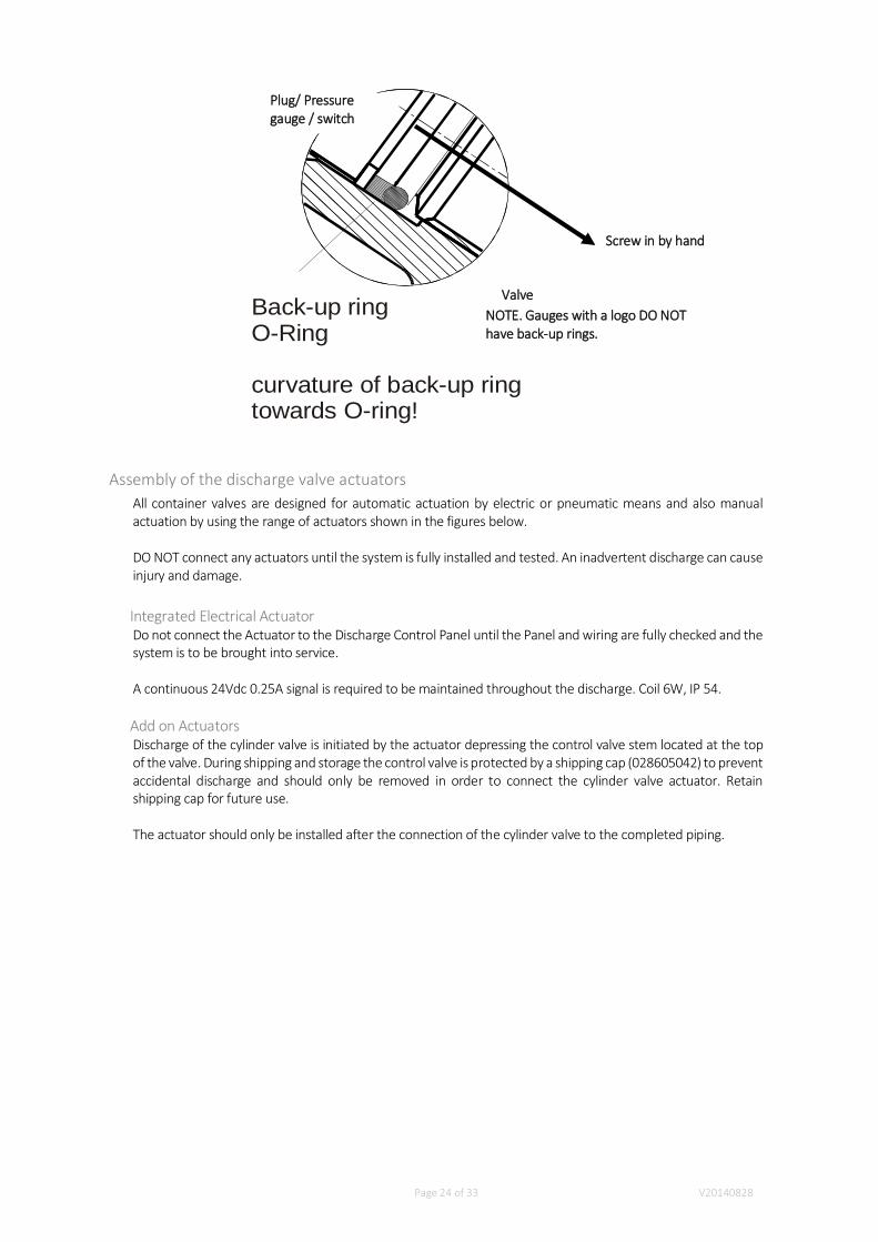
Before screwing in the gauge, make sure that the O-ring seal and back-up ring are not damaged. Ifreplacement is required, note the installation diagram below (O-ring towards the pressure).
Remove the pressure port plug (4mm hexagon key) and screw in by hand the pressure gauge or pressuregauge (do not tighten) and turn back a maximum of one revolution for correct orientation.
Use only original connecting parts designed for these valves.
Page 24 of 33 V20140828
Back-up ringO-Ring
curvature of back-up ringtowards O-ring!
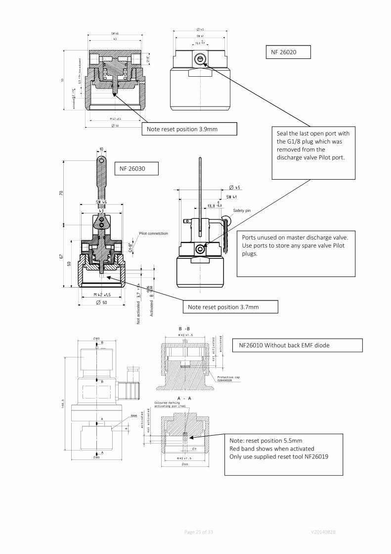
Assembly of the discharge valve actuatorsAll container valves are designed for automatic actuation by electric or pneumatic means and also manualactuation by using the range of actuators shown in the figures below.
DO NOT connect any actuators until the system is fully installed and tested. An inadvertent discharge can causeinjury and damage.
Integrated Electrical ActuatorDo not connect the Actuator to the Discharge Control Panel until the Panel and wiring are fully checked and thesystem is to be brought into service.
A continuous 24Vdc 0.25A signal is required to be maintained throughout the discharge. Coil 6W, IP 54.
Add on ActuatorsDischarge of the cylinder valve is initiated by the actuator depressing the control valve stem located at the topof the valve. During shipping and storage the control valve is protected by a shipping cap (028605042) to preventaccidental discharge and should only be removed in order to connect the cylinder valve actuator. Retainshipping cap for future use.
The actuator should only be installed after the connection of the cylinder valve to the completed piping.
Valve
Plug/ Pressuregauge / switch
NOTE. Gauges with a logo DO NOThave back-up rings.
Screw in by hand
Page 25 of 33 V20140828
activ
ated
Not
activ
ated
Act
ivat
ed
Not
activ
ated
Pilot connetction
Safety pin
146.5
80
60
8
SW46
A - A
B -B
A
A
B
B
42M x1.5
50
4
activated
not
activated
Coloured markingactivating pin (red)
42M x1.5
Protective cap028400028
not
activated
activated
NF 26020
NF 26030
Note reset position 3.9mm
Note reset position 3.7mm
NF26010 Without back EMF diode
Note: reset position 5.5mmRed band shows when activatedOnly use supplied reset tool NF26019
Seal the last open port withthe G1/8 plug which wasremoved from thedischarge valve Pilot port.
Ports unused on master discharge valve.Use ports to store any spare valve Pilotplugs.

Page 26 of 33 V20140828
Important
Before fitting the Actuator to the valve check that.The cylinders are secured and the valves have been connected to the pipe work.The Shipping cap (028605042) is removed. Never leave the valve without the cap or actuatorfitted.Ensure that the Actuator is not activated and is in the reset position see Figures above. Anactivated Actuator would cause an unintentional release while mounting the Actuator onto thevalve.
Connect the Actuators to the valves via the M42x1.5 connecting thread with a torque of 50Nm +0 -15Nm.Ensure that no contamination or foreign objects have entered the bore hole of the control valve.
If any hissing or discharge of gas is noticed during connection of the actuator - STOP AT ONCE and disconnectactuator from the valve.
Page 27 of 33 V20140828
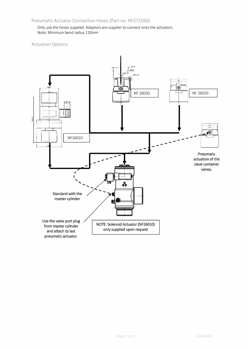
Pneumatic Actuator Connection Hoses (Part no. NF271560)Only use the hoses supplied. Adaptors are supplier to connect onto the actuators.Note: Minimum bend radius 110mm
Actuation Options
Pneumaticactuation of theslave container
valves.
Standard with themaster cylinder
Use the valve port plugfrom master cylinder
and attach to lastpneumatic actuator.
NF 26030 NF 26020
NF26010
NOTE: Solenoid Actuator (NF26010)only supplied upon request
Page 28 of 33 V20140828
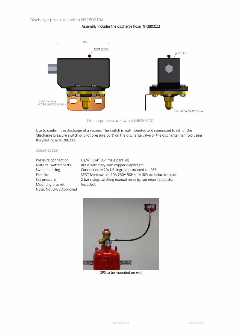
Discharge pressure switch NF280210AAssembly includes the discharge hose (NF280211)
Discharge pressure switch (NF280210)
Use to confirm the discharge of a system. The switch is wall mounted and connected to either the‘discharge pressure switch or pilot pressure port’ on the discharge valve or the discharge manifold usingthe pilot hose NF280211.
Specification
Pressure connection G1/4” (1/4” BSP male parallel)Material wetted parts Brass with beryllium copper diaphragmSwitch housing Connection M20x1.5. Ingress protected to IP65Electrical SPDT Microswitch 10A 250V 50Hz, 1A 30V dc inductive load.Set pressure 2 bar rising. Latching manual reset by top mounted button.Mounting bracket Included.Note: Not LPCB Approved
[DPS to be mounted on wall]

Page 29 of 33 V20140828
6.
1. 7.
2.3.
4.
5.
9. 8.
Glossary: 1. Pneumatic manual actuator 2. Integrated Solenoid 3. Actuation hose 4. Outlet adaptor 5.Cylinder Pressure gauge 6. Discharge pressure switch 7. Pneumatic actuator 8. Cylinder strap 9. Unistrut
(supplied by customer)
Installation Check ListPrior to verification and test the installer should check the following:
ContainersCorrect weightPressureFixed
PipingContinuousBlow throughCorrect sizeFlow splits correctFixed
NozzleCorrect size and orificeCorrect typeOrientation
LabelsContainerManual releaseDoor warningSystem installer/maintenance
Page 30 of 33 V20140828
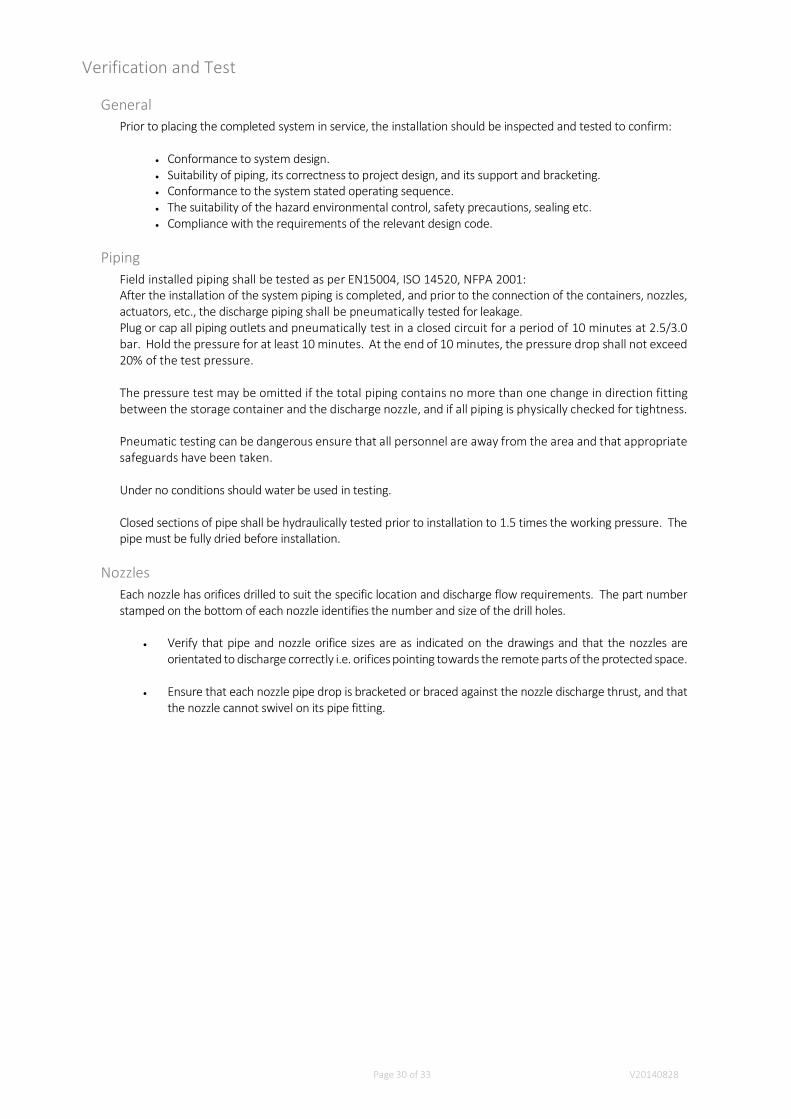
Verification and Test
GeneralPrior to placing the completed system in service, the installation should be inspected and tested to confirm:
Conformance to system design.Suitability of piping, its correctness to project design, and its support and bracketing.Conformance to the system stated operating sequence.The suitability of the hazard environmental control, safety precautions, sealing etc.Compliance with the requirements of the relevant design code.
PipingField installed piping shall be tested as per EN15004, ISO 14520, NFPA 2001:After the installation of the system piping is completed, and prior to the connection of the containers, nozzles,actuators, etc., the discharge piping shall be pneumatically tested for leakage.Plug or cap all piping outlets and pneumatically test in a closed circuit for a period of 10 minutes at 2.5/3.0bar. Hold the pressure for at least 10 minutes. At the end of 10 minutes, the pressure drop shall not exceed20% of the test pressure.
The pressure test may be omitted if the total piping contains no more than one change in direction fittingbetween the storage container and the discharge nozzle, and if all piping is physically checked for tightness.
Pneumatic testing can be dangerous ensure that all personnel are away from the area and that appropriatesafeguards have been taken.
Under no conditions should water be used in testing.
Closed sections of pipe shall be hydraulically tested prior to installation to 1.5 times the working pressure. Thepipe must be fully dried before installation.
NozzlesEach nozzle has orifices drilled to suit the specific location and discharge flow requirements. The part numberstamped on the bottom of each nozzle identifies the number and size of the drill holes.
Verify that pipe and nozzle orifice sizes are as indicated on the drawings and that the nozzles areorientated to discharge correctly i.e. orifices pointing towards the remote parts of the protected space.
Ensure that each nozzle pipe drop is bracketed or braced against the nozzle discharge thrust, and thatthe nozzle cannot swivel on its pipe fitting.
Page 31 of 33 V20140828
ElectricalAll testing of the extinguishing system electrical circuits shall be carried out in accordance with the fire fightingsystem control panel manual.
All testing is to be performed with the actuator disconnected from the valve.
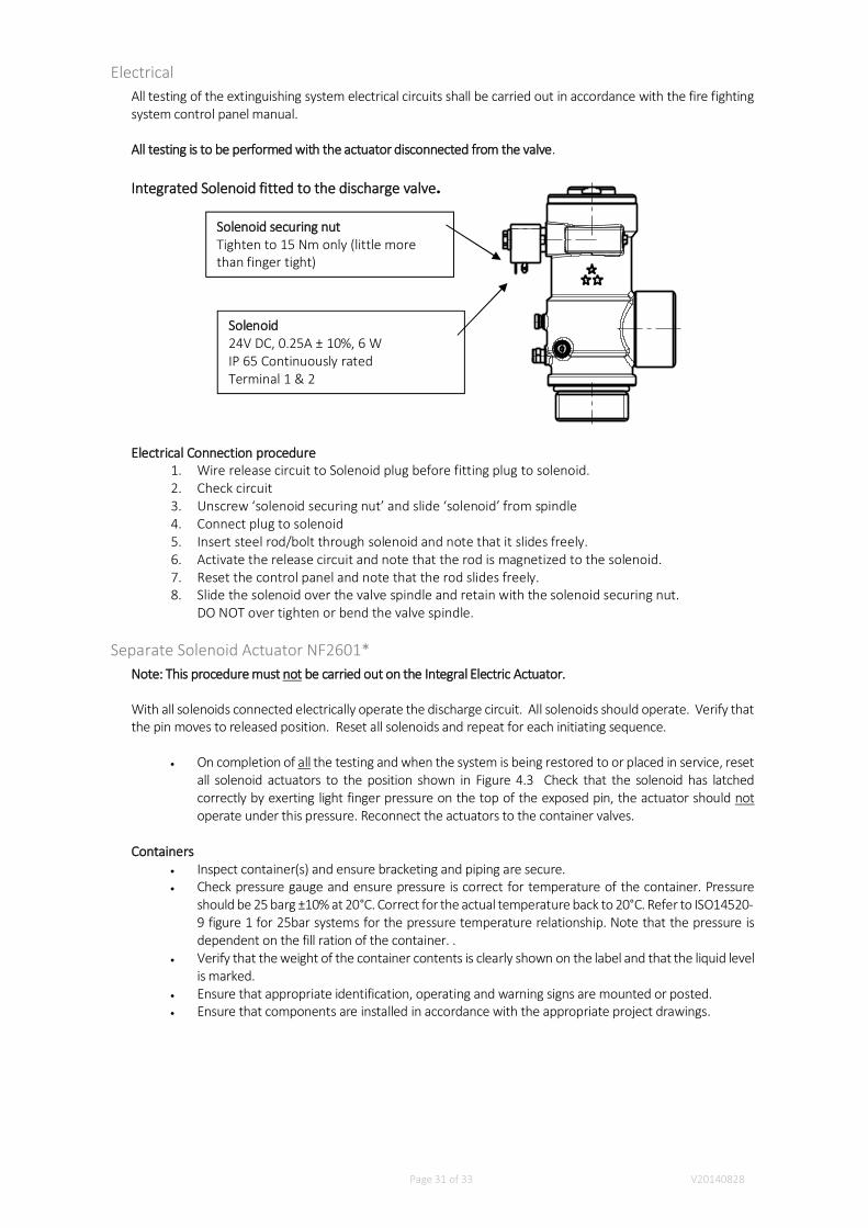
Integrated Solenoid fitted to the discharge valve.
Electrical Connection procedure1. Wire release circuit to Solenoid plug before fitting plug to solenoid.2. Check circuit3. Unscrew ‘solenoid securing nut’ and slide ‘solenoid’ from spindle4. Connect plug to solenoid5. Insert steel rod/bolt through solenoid and note that it slides freely.6. Activate the release circuit and note that the rod is magnetized to the solenoid.7. Reset the control panel and note that the rod slides freely.8. Slide the solenoid over the valve spindle and retain with the solenoid securing nut.
DO NOT over tighten or bend the valve spindle.
Separate Solenoid Actuator NF2601*Note: This procedure must not be carried out on the Integral Electric Actuator.
With all solenoids connected electrically operate the discharge circuit. All solenoids should operate. Verify thatthe pin moves to released position. Reset all solenoids and repeat for each initiating sequence.
On completion of all the testing and when the system is being restored to or placed in service, resetall solenoid actuators to the position shown in Figure 4.3 Check that the solenoid has latchedcorrectly by exerting light finger pressure on the top of the exposed pin, the actuator should notoperate under this pressure. Reconnect the actuators to the container valves.
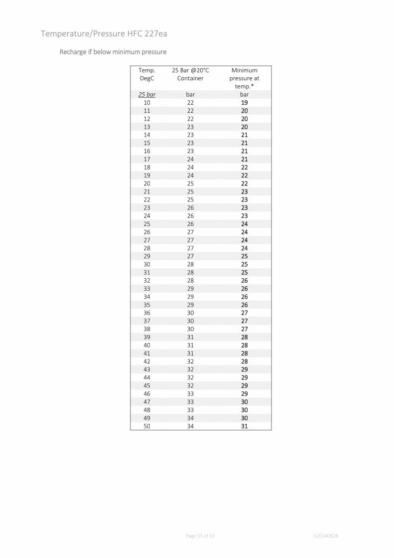
ContainersInspect container(s) and ensure bracketing and piping are secure.Check pressure gauge and ensure pressure is correct for temperature of the container. Pressureshould be 25 barg ±10% at 20°C. Correct for the actual temperature back to 20°C. Refer to ISO14520-9 figure 1 for 25bar systems for the pressure temperature relationship. Note that the pressure isdependent on the fill ration of the container. .Verify that the weight of the container contents is clearly shown on the label and that the liquid levelis marked.Ensure that appropriate identification, operating and warning signs are mounted or posted.Ensure that components are installed in accordance with the appropriate project drawings.
Solenoid securing nutTighten to 15 Nm only (little morethan finger tight)
Solenoid24V DC, 0.25A ± 10%, 6 WIP 65 Continuously ratedTerminal 1 & 2
Page 32 of 33 V20140828
Maintenance
The system shall be regularly inspected to ensure that it is fully operational. The interval betweeninspections and the scope are covered in NFPA 2001 and ISO 14520-1.
Before attempting any maintenance inform the system owners that the maintenance is about to becarried out to ensure that they have made other arrangements for the protection of the protected spaceduring the period that the system will NOT be available.
Isolate the discharge circuit electrically at the control panel and for added safety remove the electricalconnection to all solenoid actuators. Remove all actuators from the discharge valves.
The inspection shall include:The protected space to ensure that there have NOT been any changes affecting the design ordischarge retention.Damage to any equipment or pipe workThe Alarm and Control system should also be inspected at the same time. Pay particularattention to the interface between the suppression system and the control system.Auxiliary equipment such as pressure switches, door closures, dampers, air handling shutdownmust be checked for correct operation.Agent containers. These shall be check weighed or the contents checked with a liquid leveldevice as well as the cylinder pressure. This needs to be compensated for temperature and theagent fill ratio. Guidance is given in NFPA 2001 and ISO 14520-1. Should the Contents or Pressureshow a loss trend or more than 5% by weight or 10% by pressure then these must be withdrawnfrom service and recharged.Pilot and Discharge hoses are to be checked every 12 months for any signs of deterioration eitherin the metal fittings or hose. Hoses will deteriorate when subjected to continuous hightemperatures, excessive bending or high Ultra Violate Light levels. The hoses should be replacedevery 10 years or sooner if there any signs of deterioration.Check Valves are to be checked externally every 12 months for any signs of deterioration. Theinternal seals should be replaced every 10 years.
Recharge after dischargeDisconnect and remove all of the actuators and cylinder pressure switches.Fit anti recoil caps to all valves prior to removing them from their racking.Only skilled and trained operatives shall recharge the cylinders while following the valvemaintenance and recharge procedures.Before returning to service all cylinders should be conditioned for at least 24 hours for theNitrogen to be absorbed and the temperature stabilised. Check for leaks at all joints, check weighthe cylinder (note the extra weight of the Nitrogen) and cylinder pressure.Enter the details on the fill label.Return to service.
Page 33 of 33 V20140828
Temperature/Pressure HFC 227ea
Recharge if below minimum pressure
Temp.DegC
25 Bar @20°CContainer
Minimumpressure at
temp.*25 bar bar bar
10 22 1911 22 2012 22 2013 23 2014 23 2115 23 2116 23 2117 24 2118 24 2219 24 2220 25 2221 25 2322 25 2323 26 2324 26 2325 26 2426 27 2427 27 2428 27 2429 27 2530 28 2531 28 2532 28 2633 29 2634 29 2635 29 2636 30 2737 30 2738 30 2739 31 2840 31 2841 31 2842 32 2843 32 2944 32 2945 32 2946 33 2947 33 3048 33 3049 34 3050 34 31