HFC 227 ea - aguilera.esaguilera.es/documentacion/Extinción HFC 227ea/Manuales/hfc227ea... · HFC...
40
HFC 227 ea AEX Engineered Fire Suppression Systems Design, Installation, Operation and Maintenance Manual V1.0 April 2012
Transcript of HFC 227 ea - aguilera.esaguilera.es/documentacion/Extinción HFC 227ea/Manuales/hfc227ea... · HFC...

HFC 227 ea
AEX Engineered Fire Suppression Systems
Design, Installation, Operation and Maintenance Manual
V1.0 April 2012

2

AEX-MAN-200-0.0 V1.0 AGUILERA EXTINCION
3
INDEX 1 GENERAL INFORMATION .........................................................................................................................................7
1.1 INTRODUCTION.................................................................................................................................................7 1.2 SYSTEM DESCRIPTION ...................................................................................................................................7
1.2.1 General .......................................................................................................................................................7 1.2.2 Extinguishing Agent ...................................................................................................................................8 1.2.3 Exposure Limitations................................................................................................................................10 1.2.4 Toxicity ......................................................................................................................................................10 1.2.5 Noise .........................................................................................................................................................10 1.2.6 Turbulence................................................................................................................................................10 1.2.7 Chilling ......................................................................................................................................................10 1.2.8 Visibility .....................................................................................................................................................10 1.2.9 Pressure....................................................................................................................................................11
2 OPERATION...............................................................................................................................................................12 3 COMPONENTS..........................................................................................................................................................13
3.1 FUNCTIONAL DESCRIPTION.........................................................................................................................13 3.2 COMPONENT DESCRIPTION ........................................................................................................................14
3.2.1 Cylinder / Valve Assembly.......................................................................................................................14 3.2.2 Control Head.............................................................................................................................................16 3.2.3 Pressure Gauge. ......................................................................................................................................17 3.2.4 Actuation Hose. ........................................................................................................................................18 3.2.5 Discharge Hose........................................................................................................................................18 3.2.6 Tees, Elbows and Adapters.....................................................................................................................19 3.2.7 Check Valve..............................................................................................................................................20 3.2.8 Manifold.....................................................................................................................................................20 3.2.9 Discharge Indicator ..................................................................................................................................21 3.2.10 Discharge Nozzle .....................................................................................................................................21
4 SYSTEM DESIGN......................................................................................................................................................24 4.1 DETERMINE HAZARD TYPE ..........................................................................................................................24 4.2 DETERMINE CONCENTRATION PERCENTAGE.........................................................................................24
4.2.1 Class A Hazards.......................................................................................................................................24 4.2.2 Class B Flammable Liquids.....................................................................................................................24
4.3 SAFETY RECOMMENDATIONS.....................................................................................................................25 4.3.1 Normally Unoccupied Areas....................................................................................................................25 4.3.2 Unoccupiable Areas.................................................................................................................................25 4.3.3 General Rules – Occupiable Areas.........................................................................................................26
4.4 DETERMINE AGENT QUANTITY....................................................................................................................26 4.4.1 Determine the Hazard Volume................................................................................................................26 4.4.2 Calculate Agent Required........................................................................................................................27 4.4.3 Altitude Correction Factors ......................................................................................................................28 4.4.4 Determine Actual Concentration at Maximum Temperature.................................................................29 4.4.5 Leakage ....................................................................................................................................................30
4.5 CONTAINER SELECTION ...............................................................................................................................31 4.5.1 Container Size and Fill Range.................................................................................................................31 4.5.2 Container Location(s)...............................................................................................................................31 4.5.3 Storage Temperature Limitations............................................................................................................32
4.6 NOZZLE SELECTION.......................................................................................................................................32 4.7 TEE ORIENTATION ..........................................................................................................................................33
5 INSTALLATION ..........................................................................................................................................................34 5.1 SYSTEM INSTALLATION ................................................................................................................................34 5.2 AGENT STORAGE CONTAINERS..................................................................................................................34 5.3 CONTAINER MOUNTING ................................................................................................................................34 5.4 FINAL SYSTEM CHECKOUT ..........................................................................................................................34 5.5 HAZARD AREA CHECK...................................................................................................................................35

AEX-MAN-200-0.0 V1.0 Mar 2012
4
5.5.1 Area Configuration ...................................................................................................................................35 5.5.2 Area Leakage ...........................................................................................................................................35 5.5.3 Enclosure Integrity Door Fant Testing ....................................................................................................35
6 SYSTEM MAINTENANCE.........................................................................................................................................36 6.1 SYSTEM MAINTENANCE................................................................................................................................36 6.2 DISCHARGE PIPING........................................................................................................................................36 6.3 DISCHARGE NOZZLES...................................................................................................................................36 6.4 AGENT STORAGE CONTAINERS..................................................................................................................36
6.4.1 Valve Reconditioning ...............................................................................................................................37 6.5 REMOTE PNEUMATIC ACTUATION..............................................................................................................38 6.6 CONTAINER TEST AND INSPECTION..........................................................................................................38
AEX-MAN-200-0.0 V1.0 Mar 2012
5
FOREWORD: This manual is written for those who are installing an AEX Engineered Fire Suppression Systems using HFC 227 ea as extinguishing agent. Aguilera Extinción assumes no responsibility for the application of any systems other than those addressed in this manual. The technical data contained herein is limited strictly for information purposes only. Aguilera Extinción believes this data to be accurate, but it is published and presented without any guarantee or warranty whatsoever. AEX Engineered Fire Suppression Systems are to be designed, installed, inspected, maintained, tested and recharged by qualified, trained personnel in accordance with the following:
Standard of the national Fire Protection Association no.2001, titled Clean Agent Fire Extinguishing Systems. European Standard EN 15004-1, titled Gas Extinguishing Systems, Design, Installation and Maintenance.
For any questions regarding the information presented in this manual, please refer to: Aguilera Extincion S.L . Av. Alfonso Peña Boeuf 6 PI Fin de Semana, 28022, Madrid. Phone: +34 91 3121656 Fax: +34 91 3295820 E-mail: extinció[email protected]

AEX-MAN-200-0.0 V1.0 Mar 2012
6
SAFETY SUMMARY HFC 227 ea fire suppression systems use pressurized equipment; therefore personnel responsible for fire suppression systems must be aware of the risk associated with the improper handling, installation or maintenance of this equipment. All service personnel must be thoroughly trained in the proper handling, installation and service of HFC227 ea equipment and follow the instructions used in this manual. Warnings and cautions are provided within this manual at appropriate locations. These warnings and cautions are to be followed at all times. Failure to do so may result in serious injury to personnel. In addition, Material Safety Data Sheet for HFC 227 ea and nitrogen are provided. Personnel must be familiar with the information contained on these data sheets. WARNING
Pressurized (charged) cylinders are extremely hazardous and if not handled properly are capable of violent discharge which may cause serious body injuries, death and property damage. Read, Understand and always follow the operation and maintenance manuals, owners manuals, service manuals that are provided with the individual systems.

AEX-MAN-200-0.0 V1.0 Mar 2012
7
1 GENERAL INFORMATION 1.1 INTRODUCTION Aguilera HFC 227 ea AEX Engineered Fire Suppression Systems are designed according to the European Standard EN 15004-1, titled Gas Extinguishing Systems, Design, Installation and Maintenance. These systems are designed for total flooding. In any situation not covered by this manual, the application and installation of the system must meet the requirement of the standard as stated. In any case, all installations must meet the requirements of the local Authority Having Jurisdiction (AHJ). The complexity of two-phase flow does not allow for any simple method of manual gas HFC 227 ea calculation. Therefore, the flow calculations and design criteria described in this manual have been incorporated into a computer software program. The calculations are based on conserving mass, energy and momentum in the pipe network. The routine calculates the flow in quasi-steady state steps from the initiation of the discharge to the final gas blowdown. 1.2 SYSTEM DESCRIPTION 1.2.1 General AEX Engineered Fire Suppression Systems are used to suppress fires in specific hazards or equipment located where an electrically non-conductive agent is required, when agent clean up becomes a problem, where extinguishing capability with low weight is a factor and where the hazard is normally occupied by personnel. AEX Engineered Fire Suppression Systems are designed to protect the following type of class fires:
Class A surface type fires. Class B flammable liquids. Class C energized electrical equipment.
AEX Engineered Fire Suppression Systems are provided to protect the following type of specific hazards:
Telecommunications devices. Process control rooms. Data processing devices. High value facilities (medical, industrial….). Libraries, museums, art galleries. Anechoic chambers. Flammable liquid storage areas.
For other hazards beyond the above, the designer must consult with Aguilera Extincion and the Standards NFPA 2001 and EN-15004-1. According to these Standards, HFC 227 ea shall not be used on fires involving the following materials, unless they have been tested to the satisfaction of the Authority Having Jurisdiction (AHJ).
Certain chemicals or mixtures of chemicals, such as cellulose nitrate and gunpowder, that are capable of rapid oxidation in the absence of air. Reactive metals such as lithium, sodium, potassium, magnesium, titanium, zirconium, uranium and plutonium. Metal hydrides. Chemicals capable of undergoing autothermal decomposition, such as certain organic peroxides and hydrazine.

AEX-MAN-200-0.0 V1.0 Mar 2012
8
AEX Engineered Fire Suppression Systems are provided to protect the following has a operation temperature range for all its components of 32ºF to 130 ºF (0 ºC to 54 ºC). The program is designed for a temperature of 70 ºF (21 ºC). Therefore, the container operating and storage temperature must be in the range of 60 ºF to 80 ºF (16 ºC to 27 ºC) for a single unbalanced system protecting two or more separate hazards. If the container temperature is outside this range, an insufficient quantity of extinguishing agent may be discharged from one or more discharge nozzles. 1.2.2 Extinguishing Agent HFC 227 ea (1,1,1,2,3,3,3 – heptafluoropropane) is a compound of carbon, fluorine and hydrogen (CF3CHFCF3). It is colorless, odorless and electrically non-conductive. It suppresses fire by a combination of chemical and physical mechanism with a minimal effect on the available oxygen. This allow people to breathe and see, permitting them to leave the fire are safely. HFC-227ea’s mechanism of extinguishing fires is considered active. Its primary action is through physically cooling the fire at the molecular level. HFC-227ea belongs to the same class of agents used in the refrigeration industry; therefore, it is an efficient heat transfer agent. HFC-227ea removes the thermal energy from the fire to the extent where the combustion reaction cannot sustain itself. HFC 227 ea is acceptable for use in occupied spaces when used in accordance with the United States Environmental Protection Agency (EPA) Significant New Alternatives Policy (SNAP) program rules. Although HFC 227 ea is considered non toxic for humans in the concentrations required for extinguishing most fires, certain safety considerations should be observed when the agent is applied and handled. The agent discharge may create a hazard to people from the decomposition agent and products, when the agent is exposed to fire or other hot surfaces. The exposure to the agent is generally of less concern than the exposure to the decomposition products. Unnecessary exposure to the agent or its decomposition products should be avoided. For safety considerations, refer to Material Safety Data Sheet. The storage of the agent is in steel containers at 610 PSIG at 70 ºF (42 bar at 21 ºC) as a liquid with dry nitrogen added to improve the discharge flow and characteristics.
AEX-MAN-200-0.0 V1.0 Mar 2012
9
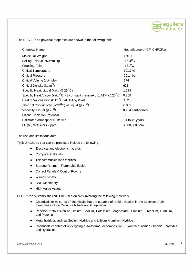
The HFC 227 ea physical properties are shown in the following table:
Chemical Name Heptafluoropro (CF3CHFCF3)
Molecular Weight 170.03 Boiling Point @ 760mm Hg -16.4oC Freezing Point -131oC Critical Temperature 101.7oC Critical Pressure 29.1 bar Critical Volume (cc/mole) 274 Critical Density (kg/m3) 621 Specific Heat, Liquid (kj/kg @ 25oC) 1.184 Specific Heat, Vapor (kj/kgoC) @ constant pressure of 1 ATM @ 25oC 0.808 Heat of Vaporization (kj/kgoC) at Boiling Point 132.6 Thermal Conductivity (W/moC) of Liquid @ 25oC 0.069 Viscosity, Liquid @ 25oC 0.184 centipoises Ozone Depletion Potential 0 Estimated Atmospheric Lifetime 31 to 42 years LC50 (Rats; 4 hrs – ppm) >800,000 ppm
The use and limitations are: Typical hazards that can be protected include the following:
Electrical and electronic hazards
Computer Cabinets
Telecommunications facilities
Storage Rooms – Flammable liquids
Control Panels & Control Rooms
Wiring Closets
CNC Machinery
High Value Assets HFC-227ea systems shall NOT be used on fires involving the following materials.
Chemicals or mixtures of chemicals that are capable of rapid oxidation in the absence of air. Examples include Cellulose Nitrate and Gunpowder.
Reactive metals such as Lithium, Sodium, Potassium, Magnesium, Titanium, Zirconium, Uranium, and Plutonium
Metal hydrides such as Sodium Hydride and Lithium Aluminum Hydride
Chemicals capable of undergoing auto-thermal decomposition. Examples include Organic Peroxides and Hydrazine.
AEX-MAN-200-0.0 V1.0 Mar 2012
10
1.2.3 Exposure Limitations Although HFC-227ea is considered to be non-toxic, limitations to exposure may exist. Consult EN 15004-5, ISO 14520, NFPA Standard 2001, or the appropriate national standard to determine if such limitations exist. The following definitions are commonly used to describe exposure limitations.
NOAEL – No Observed Adverse Effect Level. This is the highest concentration at which no adverse toxicological or physiological effect has been observed. For HFC-227ea Systems, the NOAEL concentration is 9% by volume.
LOAEL – Lowest Observable Adverse Effect Level. This is the lowest concentration at which an adverse toxicological or physiological effect has been observed. For HFC-227ea Systems, the LOAEL concentration is 10.5% by volume.
WARNING: The discharge of HFC-227ea Systems to extinguish a fire can result in potential hazards to personnel. These may include the natural form of the agent, or the products of combustion, that result from exposure of the agent to the fire or hot surfaces. Unnecessary exposure of personnel to the natural agent or the products of decomposition from a fire should be avoided. The requirement for pre-discharge alarms and time delays is intended to prevent unnecessary exposure to humans where their presence is not critical to the operation of the area. Suitable safeguards shall be provided to ensure prompt evacuation of [and prevent entry into] all protected areas after discharge. 1.2.4 Toxicity With a database in excess of seventy toxicity tests, HFC-227ea has been extensively tested and approved by institutions and agencies around the world. The LC50 toxicity rating for HFC-227ea is greater than 800,000ppm. When you consider that most HFC-227ea systems are designed for concentrations providing 105,000ppm or less, it is evident that HFC-227ea is safe to use. HFC-227ea will decompose to form halogen acids when exposed to extremely high temperatures. The formation of these acids is minimized by proper system design and installation of the piping system to deliver the agent quickly. The generation of by-products from the HFC-227ea discharge will be minimal when properly applied. 1.2.5 Noise The high-pressure discharge from the nozzle(s) of a system can cause noise that is loud enough to be startling, but ordinarily insufficient to cause traumatic injury. 1.2.6 Turbulence The high velocity discharge from the nozzle(s) can be sufficient enough to dislodge substantial objects located directly in the discharge path. Enough general turbulence may be created within the enclosure to move unsecured paper and light objects. 1.2.7 Chilling Direct contact with the vaporizing agent being discharged from the nozzle(s) will have a chilling effect on objects and can cause frostbite burns to the skin. The liquid phase vaporizes rapidly when mixed with air, thus limiting the hazard to the immediate vicinity of the discharge nozzle. 1.2.8 Visibility Although HFC-227ea is odorless, discharging the agent into a humid atmosphere may cause a reduction in visibility for a brief period of time due to condensation of water vapor normally present in the room atmosphere.
AEX-MAN-200-0.0 V1.0 Mar 2012
11
1.2.9 Pressure The normal operating pressure of AEX Engineered Fire Suppression Systems is 42 bar @ 21oC. This is accomplished by adding a charge of nitrogen to the HFC-227ea after filling the container. Since these are pressurized vessels, care must be observed when handling, filling, and transporting storage containers. Refer to the appropriate transportation requirements for the area in which the system is being installed for guidance regarding marking, transportation methods, etc.

AEX-MAN-200-0.0 V1.0 Mar 2012
12
2 OPERATION The HFC 227 ea is held in the cylinder compressed by a discharge valve. When the valve is actuated by a control head, the valve closing device is displaced and the compressed liquid escapes through the discharge port of the valve and is directed through the distribution pipe to the nozzles. The nozzles will provide the proper flow rate and distribution of HFC 227 ea. The following operating procedures are considered in a stand-by systems status:
Automatic Operation, where the system is operated automatically by means of a detection and control system. Everyone must evacuate the hazard are promptly upon hearing the pre-discharge alarm. Make sure no one enters the hazard area and call the fire department immediately.
Local Manual Operation, although is not part of normal system actuation and should only be used in an emergency as a last resort. The following steps are to be taken:
1. To locate the proper cylinder for the hazard to be protected. In case of several cylinders and hazards, appropriate signal must be used.
2. To remove the safety pull pin from the cylinder control head. 3. To operate the manual lever, following the instructions on the lever or control head nameplate. 4. To leave the hazard immediately. 5. To allow no one to enter the hazard area and call the fire department immediately.
In case of post-fire operation, the maintenance must be performed by qualified personnel. For cylinder recharge, return all cylinders to an Aguilera official distributor or other qualified refill agency. Both operations must be performed according to the procedures outlined in chapter 5 (Maintenance).
AEX-MAN-200-0.0 V1.0 Mar 2012
13
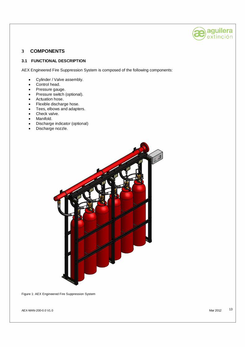
3 COMPONENTS 3.1 FUNCTIONAL DESCRIPTION
AEX Engineered Fire Suppression System is composed of the following components:
Cylinder / Valve assembly. Control head. Pressure gauge. Pressure switch (optional). Actuation hose. Flexible discharge hose. Tees, elbows and adapters. Check valve. Manifold. Discharge indicator (optional) Discharge nozzle.
Figure 1: AEX Engineered Fire Suppression System
AEX-MAN-200-0.0 V1.0 Mar 2012
14
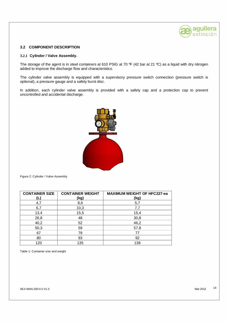
3.2 COMPONENT DESCRIPTION 3.2.1 Cylinder / Valve Assembly. The storage of the agent is in steel containers at 610 PSIG at 70 ºF (42 bar at 21 ºC) as a liquid with dry nitrogen added to improve the discharge flow and characteristics. The cylinder valve assembly is equipped with a supervisory pressure switch connection (pressure switch is optional), a pressure gauge and a safety burst disc. In addition, each cylinder valve assembly is provided with a safety cap and a protection cap to prevent uncontrolled and accidental discharge.
Figure 2: Cylinder / Valve Assembly
CONTAINER SIZE (L)
CONTAINER WEIGHT (kg)
MAXIMUM WEIGHT OF HFC227-ea (kg)
4,7 8,6 5,7 6,7 10,3 7,7 13,4 15,5 15,4 26,8 48 30,8 40,2 52 46,2 50,3 59 57,8 67 79 77 80 93 92
120 135 138 Table 1: Container size and weight

AEX-MAN-200-0.0 V1.0 Mar 2012
15
Figure 3: Pilot valve assembly
Figure 4: Slave valve assembly

AEX-MAN-200-0.0 V1.0 Mar 2012
16
3.2.2 Control Head. 3.2.2.1 Electric operated control head. The electric control head provides the electric actuation of the cylinder valve. It is operated electrically from a detection and control system or a remote manual station.
Figure 5: Electric operated control head (solenoid) Solenoid Data Sheet Coil KT10 (10W) Serie VE 131 – VE 161 24V DC 100% ED IP 65 3.2.2.2 Lever operated control head. The lever control head allows the manual operation of the cylinder valve. It is equipped with an operating lever, secured in the closed position by a safety pull pin. When removing the safety pin, the lever can easily be moved to the open position, thereby activating the cylinder valve on which it is installed
Figure 6: Lever operated control head

AEX-MAN-200-0.0 V1.0 Mar 2012
17
3.2.2.3 Pressure operated control head. The pressure operated control head allows the pressure operation of the cylinder valve through the pilot pressure. It is used in multiple cylinder systems. Pilot pressure is directed to a pressure operated control head on each cylinder valve using a flexible actuation hose.
Figure 7: Pressure operated control head 3.2.3 Pressure Gauge. It is a pressure indicator provided to indicate the pressure in the agent storage container.
Figure 8: Pressure gauge

AEX-MAN-200-0.0 V1.0 Mar 2012
18
3.2.4 Actuation Hose. The flexible actuation hose is used in multiple cylinder systems to direct the pilot pressure to a pressure operated control head on each cylinder valve.
Figure 9: Actuation hose (pilot line)
CODE HOSE SIZE CONNECTION SIZE LENGTH (mm) LD18 400
LD18-500 500 LD18BP 700
LD18BPP
3/16" BSP GAS 1/8"
2000 Table 2: Actuation hose (pilot line) 3.2.5 Discharge Hose. The HFC 227 ea is routed from the storage cylinders to the discharge piping by a flexible rubbered cover hose with wire braided reinformcements. The hose is connected to the discharge outlet of the cylinder valve and ends at the system piping or discharge manifold.
Figure 10: Discharge hose
CODE HOSE SIZE CONNECTION SIZE LENGTH (mm) L34 3/4" BSP GAS 3/4" 535
L114N 1 1/4" BSP GAS 1 1/4" 600 L112N 1 1/2" BSP GAS 1 1/2" 690
Table 3: Discharge hose

AEX-MAN-200-0.0 V1.0 Mar 2012
19
3.2.6 Tees, Elbows and Adapters. Tees, elbows and adapters connect actuation hoses to pressure operated control heads in multiple cylinder system installations.
Figure 11: Elbow, tee, adapters (pilot line)
Figure 12: Vent valve (pilot line)
Figure 13: General assembly of the pilot line

AEX-MAN-200-0.0 V1.0 Mar 2012
20
3.2.7 Check Valve Check Valves are required for all HFC-227ea Containers connected in a manifold arrangement. NFPA 2001, Section 2-1.3.5 requires all containers connected to a manifold have an automatic, mechanical, means of preventing agent loss from an open leg of a manifold if the system is activated while a container is removed for maintenance. Therefore, the Check Valves are required for each container in a manifold arrangement.
Figure 14: Check valve
CODE CONNECTION SIZE AEX/VAR12 1/2" AEX/VAR114 1 1/4" AEX/VAR112 1 1/2" Table 4: Check valve 3.2.8 Manifold The connection manifold is optional. The construction of the manifold is according to the design calculations. The material used is :
- Pipe ASTM A106 grade B. - Welded and threaded accessory ANSI B.16.11.
Figure 15: Manifold (standard)

AEX-MAN-200-0.0 V1.0 Mar 2012
21
3.2.9 Discharge Indicator It is a component, normally mounted on the discharge manifold (our standard manifold has the adapter mounted on it) although it could be mounted on any part of the distribution pipe.
It has internally a mechanical device which is moved by the gas pressure when a discharge is activated and then it is activating an electrical connection which send an electric signal to the control panel. Once is activated the reset of the device is only manually.
Figure 16: Discharge indicator 3.2.10 Discharge Nozzle There are three types of discharge nozzles.
The radial type (360 º). With 7 different sizes (1/4” ; 3/8” ; ½” ; ¾” ; 1” ; 1 ¼” ; 1 ½”). The coverage is 9 x 9 (m)
Figure 17: Radial type nozzle (360º)
AEX-MAN-200-0.0 V1.0 Mar 2012
22
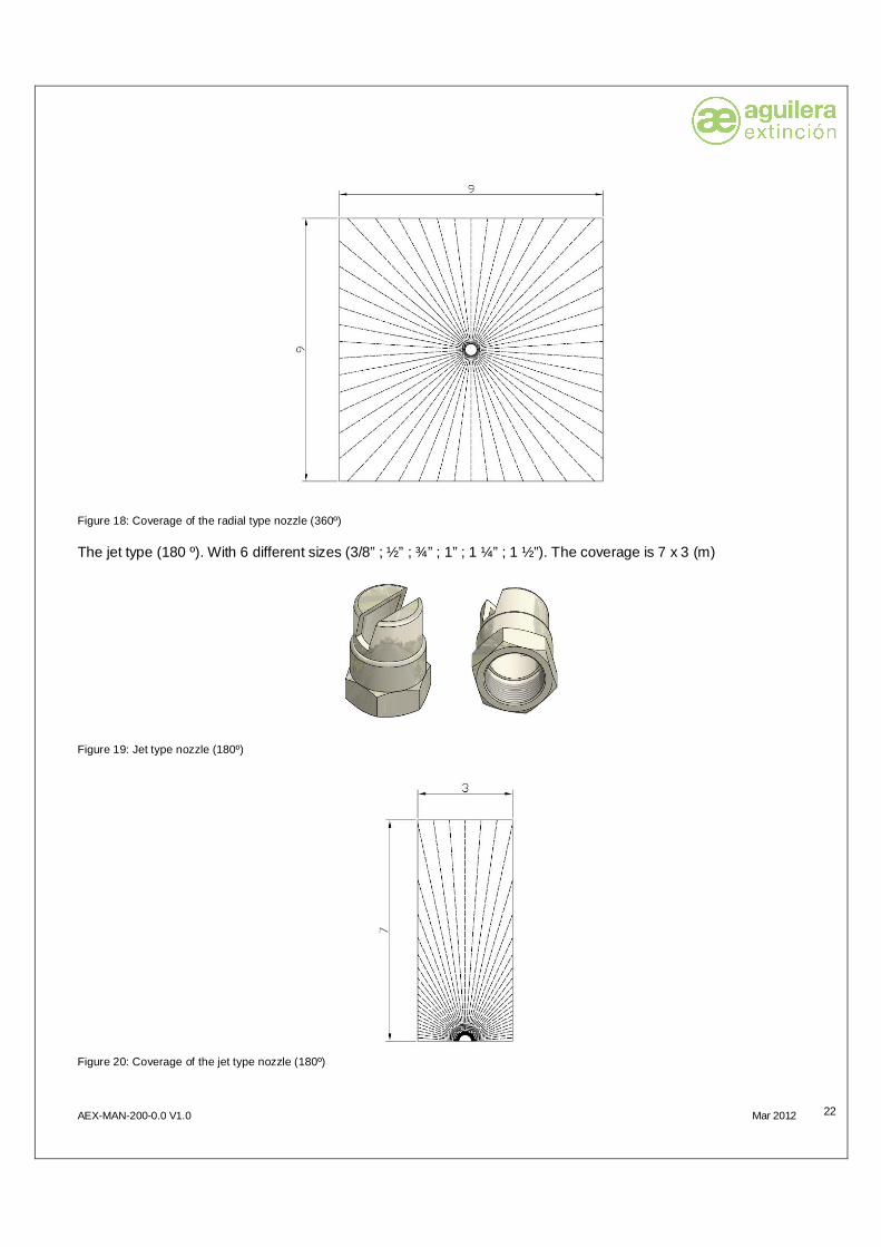
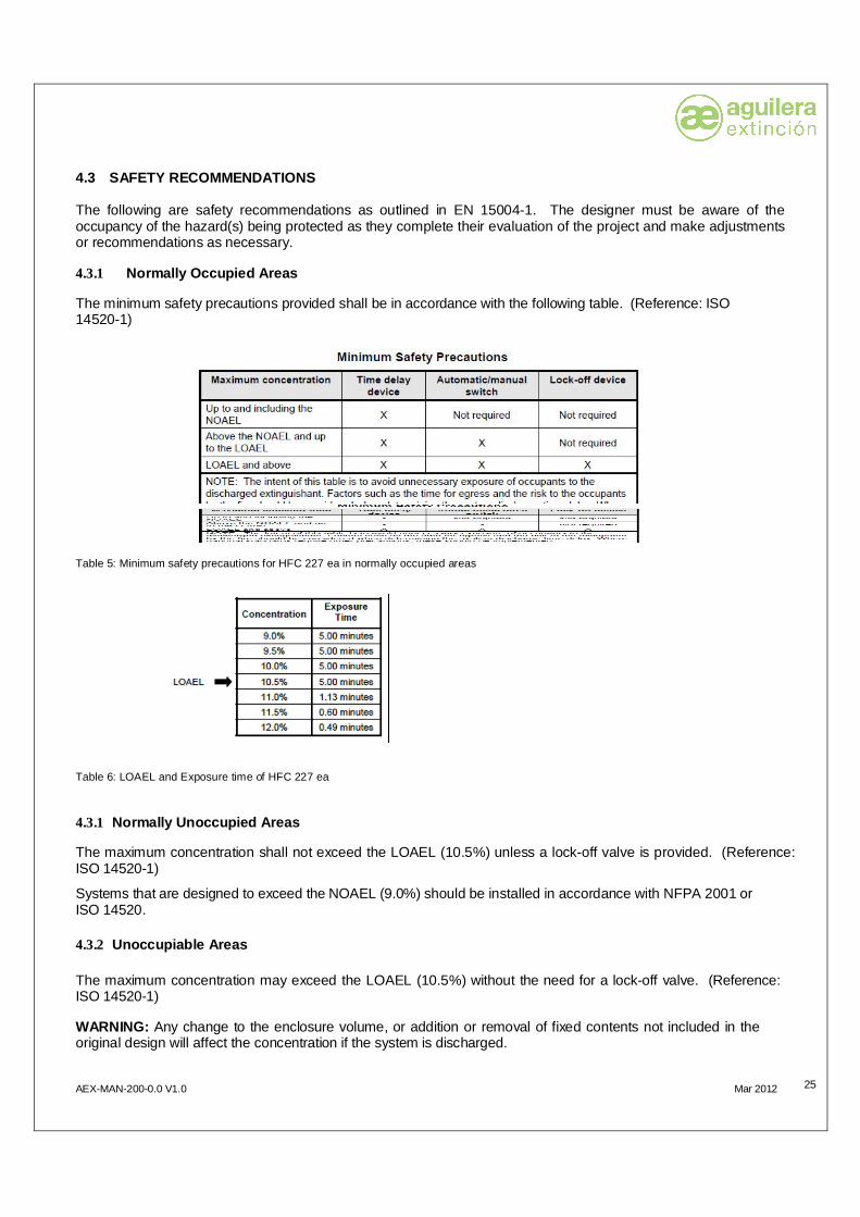
Figure 18: Coverage of the radial type nozzle (360º) The jet type (180 º). With 6 different sizes (3/8” ; ½” ; ¾” ; 1” ; 1 ¼” ; 1 ½”). The coverage is 7 x 3 (m)
Figure 19: Jet type nozzle (180º)
Figure 20: Coverage of the jet type nozzle (180º)

AEX-MAN-200-0.0 V1.0 Mar 2012
23
The window type (90 º). With 6 different sizes (3/8” ; ½” ; ¾” ; 1” ; 1 ¼” ; 1 ½”). The coverage is 5 x 5
Figure 21: Window type nozzle (90º)
Figure 22: Coverage of the window type nozzle (90º)

AEX-MAN-200-0.0 V1.0 Mar 2012
24
4 SYSTEM DESIGN This section of the manual details the steps necessary to design a AEX Engineered Fire Suppression System. The first part of this chapter will guide the user through the process of analyzing the requirements of the hazard(s) to be protected and determining the amount of agent needed. The balance of the chapter addresses the specific hardware and system design requirements for AEX Engineered Fire Suppression Systems.
The design criteria outlined in this chapter are based upon the requirements of EN 15004-1. If the system is being installed in an area governed by another standard such as NFPA Standard 2001, certain design requirements (e.g. concentration, exposure time, etc.) may differ from this document.
The design of the system and its associated piping network MUST follow the limitations outlined in this section. If the specified limitations are not maintained, the system may not supply the required quantity of extinguishing agent. 4.1 DETERMINE HAZARD TYPE The Hazard Type generally falls into one of the three following categories, and sometimes a combination thereof. The designer must be aware of the Hazard Type to determine the correct design concentration, agent quantity, etc. The three Hazard Types are: Class “A” (wood, paper, cloth – anything that leaves an ash residue after combustion) Class “B” (flammable liquids) Class “C” (electrical) 4.2 DETERMINE CONCENTRATION PERCENTAGE The following is a guideline to be used in determining the proper agent concentration percentage for the hazard(s) being protected. For combinations of fuels (hazard types) the design value for the fuel requiring the greatest concentration MUST be used. 4.2.1 Class A Hazards Systems protecting hazards containing Class A flammable materials can generally be designed for a 7.9% concentration. 4.2.2 Class B Flammable Liquids Systems protecting hazards containing Class B Flammable Liquids MUST be designed for the highest concentration required of the specific fuels listed. Therefore, the designer must perform an audit of the hazard space to identify the flammable liquids involved and their associated design concentrations. The fuel that requires the highest concentration shall be the one that determines the design concentration for the hazard.
AEX-MAN-200-0.0 V1.0 Mar 2012
25
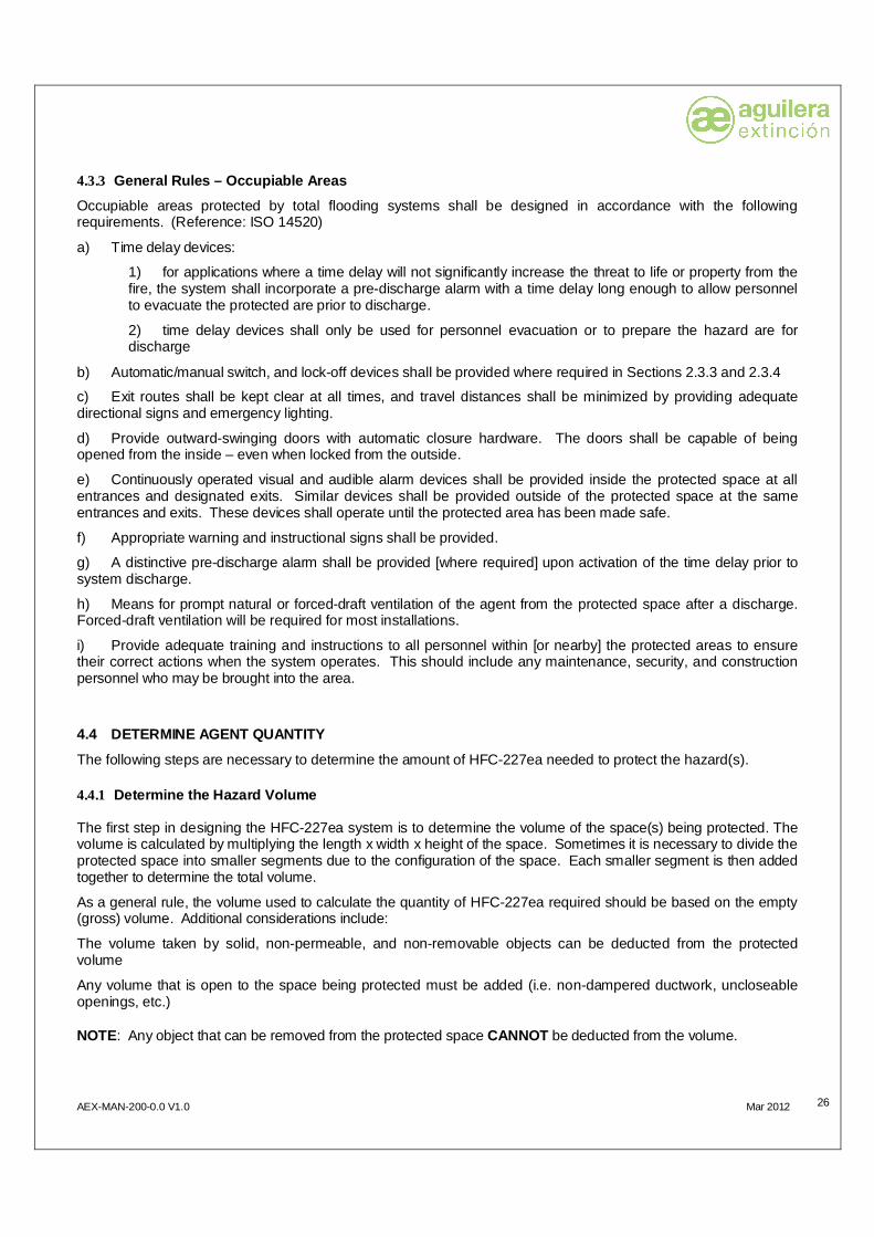
4.3 SAFETY RECOMMENDATIONS The following are safety recommendations as outlined in EN 15004-1. The designer must be aware of the occupancy of the hazard(s) being protected as they complete their evaluation of the project and make adjustments or recommendations as necessary. 4.3.1 Normally Occupied Areas The minimum safety precautions provided shall be in accordance with the following table. (Reference: ISO 14520-1)
Table 5: Minimum safety precautions for HFC 227 ea in normally occupied areas
Table 6: LOAEL and Exposure time of HFC 227 ea
4.3.1 Normally Unoccupied Areas The maximum concentration shall not exceed the LOAEL (10.5%) unless a lock-off valve is provided. (Reference: ISO 14520-1) Systems that are designed to exceed the NOAEL (9.0%) should be installed in accordance with NFPA 2001 or ISO 14520. 4.3.2 Unoccupiable Areas The maximum concentration may exceed the LOAEL (10.5%) without the need for a lock-off valve. (Reference: ISO 14520-1) WARNING: Any change to the enclosure volume, or addition or removal of fixed contents not included in the original design will affect the concentration if the system is discharged.
AEX-MAN-200-0.0 V1.0 Mar 2012
26
4.3.3 General Rules – Occupiable Areas
Occupiable areas protected by total flooding systems shall be designed in accordance with the following requirements. (Reference: ISO 14520) a) Time delay devices:
1) for applications where a time delay will not significantly increase the threat to life or property from the fire, the system shall incorporate a pre-discharge alarm with a time delay long enough to allow personnel to evacuate the protected are prior to discharge.
2) time delay devices shall only be used for personnel evacuation or to prepare the hazard are for discharge
b) Automatic/manual switch, and lock-off devices shall be provided where required in Sections 2.3.3 and 2.3.4
c) Exit routes shall be kept clear at all times, and travel distances shall be minimized by providing adequate directional signs and emergency lighting.
d) Provide outward-swinging doors with automatic closure hardware. The doors shall be capable of being opened from the inside – even when locked from the outside.
e) Continuously operated visual and audible alarm devices shall be provided inside the protected space at all entrances and designated exits. Similar devices shall be provided outside of the protected space at the same entrances and exits. These devices shall operate until the protected area has been made safe. f) Appropriate warning and instructional signs shall be provided.
g) A distinctive pre-discharge alarm shall be provided [where required] upon activation of the time delay prior to system discharge.
h) Means for prompt natural or forced-draft ventilation of the agent from the protected space after a discharge. Forced-draft ventilation will be required for most installations.
i) Provide adequate training and instructions to all personnel within [or nearby] the protected areas to ensure their correct actions when the system operates. This should include any maintenance, security, and construction personnel who may be brought into the area. 4.4 DETERMINE AGENT QUANTITY The following steps are necessary to determine the amount of HFC-227ea needed to protect the hazard(s). 4.4.1 Determine the Hazard Volume The first step in designing the HFC-227ea system is to determine the volume of the space(s) being protected. The volume is calculated by multiplying the length x width x height of the space. Sometimes it is necessary to divide the protected space into smaller segments due to the configuration of the space. Each smaller segment is then added together to determine the total volume.
As a general rule, the volume used to calculate the quantity of HFC-227ea required should be based on the empty (gross) volume. Additional considerations include:
The volume taken by solid, non-permeable, and non-removable objects can be deducted from the protected volume
Any volume that is open to the space being protected must be added (i.e. non-dampered ductwork, uncloseable openings, etc.) NOTE: Any object that can be removed from the protected space CANNOT be deducted from the volume.

AEX-MAN-200-0.0 V1.0 Mar 2012
27
4.4.2 Calculate Agent Required The next step in designing the HFC-227ea system is to determine the base quantity of agent required to provide the desired concentration within the hazard(s) being protected. This calculation must be based upon two important criteria: the lowest expected ambient temperature, and the design concentration as discussed in Sections 2.2.1, 2.2.2, and 2.2.3. To determine the agent quantity needed to produce the design concentration level, the Hazard Volume is multiplied by the factors as determined in the formula below. (Reference: ISO 14520)
V C M = -- (-----------) S 100 – C
Where: M = Agent Weight in kg
V = Hazard Volume / m3
C = Design Concentration, % by volume
S = Specific Vapor in m3/kg
S = k1 + k2 (t)
Where: k1 = 0,1269 k2 = 0,000513 t = temperature (o C)
NOTE: The equation to calculate S is an approximation. In ISO 14520-9 should be used to calculate the amount of
agent required for a specific volume. NOTE: As an alternative, the table on the next page has been compiled to make it an easier process for the
system designer. The information provided is derived from the formulas shown above.

AEX-MAN-200-0.0 V1.0 Mar 2012
28
(Reference: ISO 14520-9)
Table 7: Weight requirements (kg/m3) for HFC 227 ea 4.4.3 Altitude Correction Factors The design quantity of HFC-227ea shall be adjusted to compensate for ambient pressures that vary more than eleven percent [equivalent to approximately 1000m of elevation change] from standard sea level pressures [1,013 bar absolute].
The amount of agent required must be adjusted using the correction factors shown below to compensate for these effects. (Reference: ISO 14520)

AEX-MAN-200-0.0 V1.0 Mar 2012
29
The extinguishant quantity is determined by multiplying the quantity determined in 2.4.2 by the ratio of the average ambient enclosure pressure to the standard sea level pressure.
Table 8: Altitude correction factor for HFC 227 ea
4.4.4 Determine Actual Concentration at Maximum Temperature The next step is to determine the expected concentration level at the maximum temperature for the hazard(s). This is a necessary step when designing systems for occupied spaces to properly evaluate the system requirements discussed in Section 2.3. The expected concentration can be determined by applying the following formula. C = (100 x W x S) / (V + V x S)
Where: W = Agent Weight in lbs. (kg) M = Agent Weight in kg
V = Hazard Volume m3 C = Design Concentration, % by volume
S = Specific Vapor in m3/kg
S = k1 + k2 (t)
Where: k1 = 0,1269 k2 = 0,000513 t = temperature (ºC)

AEX-MAN-200-0.0 V1.0 Mar 2012
30
4.4.5 Leakage The physical characteristics of the protected space(s) must be taken into consideration when designing an HFC-227ea system. The area of uncloseable openings must be kept to a minimum to prevent loss of agent into adjacent areas – thus reducing the effectiveness of the system to extinguish a fire. Simply adding more agent is neither practical, nor effective. Therefore, all openings must be sealed or equipped with automatic closures. Forced-air ventilating systems shall be shut down or closed automatically where their continued operation would adversely affect the ability of the system to extinguish a fire. Completely self-contained recirculating ventilation systems are not required to be shutdown, but recommended. Dampers should be of the “low smoke” or 100% closing type to ensure an adequate seal and prevent leakage. Where the ventilation system is not shutdown or dampered, the volume of the associated ductwork and ventilation unit(s) shall be considered as part of the total hazard volume when determining the amount of agent needed. All enclosures must be sealed in order to achieve and maintain the desired concentration for a period of time that is sufficient for emergency personnel to respond. Under normal circumstances, the agent will extinguish the fire rapidly, thereby limiting the potential for fire damage and the creation of dangerous products of decomposition. Therefore, it is critical that the protected space is constructed to prevent any leakage from the protected space(s). The general guidelines for controlling leakage from the hazard are as follows:
Doors – All doors entering and/or exiting from the perimeter of the protected space(s) should have drop seals on the bottom, weather-stripping around the jams, latching mechanisms and door closure hardware. In addition, double doors should have a weather-stripped astragal to prevent leakage between the doors, and a coordinator to assure the proper sequence of closure. Doors that cannot be kept normally closed shall be equipped with door closure hardware and magnetic door holders that will release the door(s) upon a system alarm.
Ductwork – All ductwork leading into, or out of, the protected space(s) should be isolated with sealed, “low smoke” dampers. Dampers should be spring-loaded or motor-operated to provide 100% air shutoff upon activation.
Air Handling/Ventilation – It is recommended that all air handling/ventilation units be shutdown upon alarm to prevent leakage into other areas. If the air handling unit(s) cannot be shutdown, the volume of the associated ductwork must be added to the total volume of the protected space, and agent must be added to compensate for the additional volume.
Penetrations – All holes, cracks, gaps or penetrations of the perimeter walls defining the hazard area(s) must be sealed. Less obvious areas of leakage include wire trays, pipe chases, and floor drains. Make certain that floor drains have traps filled with a non-evaporating product to prevent leakage.
Walls – All perimeter walls that define the hazard area(s) should extend slab-to-slab, and each should be sealed top and bottom on the interior side. Where walls do not extend slab-to-slab, bulkheads will have to be installed to achieve the desired sealing characteristics.
Block Walls – Porous block walls must be sealed or the HFC-227ea agent will leak through.
A room integrity fan pressurization test is an accepted means of determining how long the protected space will hold the agent (concentration) after a discharge. In conjunction with testing the integrity of the room, the test has a program that predicts the performance of the HFC-227ea system so that the Authority Having Jurisdiction can determine if the system has been designed and installed properly.
The room integrity fan pressurization test must be performed in accordance with the manufacturer’s requirements, and ISO 14520-1, annex E.

AEX-MAN-200-0.0 V1.0 Mar 2012
31
4.5 CONTAINER SELECTION Generally, the selection of containers is determined by the amount of HFC-227ea required vs. the approved fill ranges for the various container sizes. However, additional factors such as the System Design Concept, container storage location, and flow calculation limitations may have an impact on this decision as well. 4.5.1 Container Size and Fill Range All containers must be filled within the allowable fill range mandated by EEC or EN1964, depending on the container type being used.
CONTAINER SIZE (L)
CONTAINER WEIGHT (kg)
MAXIMUM WEIGHT OF HFC227-ea (kg)
4,7 8,6 5,7 6,7 10,3 7,7 13,4 15,5 15,4 26,8 48 30,8 40,2 52 46,2 50,3 59 57,8 67 79 77 80 93 92
120 135 138
Table 9: Container size and weight 4.5.2 Container Location(s) The type and location of the storage container is based on several considerations. 1 Agent Quantity – The agent storage container(s) selected must have the capacity to store the total quantity
of agent required for the system.
2 System Type – An area might be protected by several smaller containers with independent nozzles, or it might be protected by a large capacity container that is discharged through a piping network of 2, 4, or more nozzles.
3 Extent of Piping – In systems having an unusually large piping system, the pressure drop may be too great for the location or configuration selected. In some cases, it may be necessary to relocate the container(s) closer to the hazard area(s) being protected. It may also be necessary to sub- divide the piping network into smaller configurations with separate containers.
4 Container Type – Consideration should be given to the container type required for the installation.
5 Serviceability – In general, the larger the container, the more difficult it will be to remove it from the system for maintenance and service. However, smaller containers that are located in a sub-floor space, under a computer bank, or above the ceiling over the same computer bank can be difficult as well.
6 Floor Loading – This factor must be considered when selecting a container location. Excessive floor loading may require relocating the container(s) to a more suitable location.
7 Proximity – HFC-227ea Containers should be located as close as possible to, or within the hazard that they protect.
8 Environmental Effects – DO NOT locate containers where they would be subject to physical damage, exposure to corrosive chemicals, or harsh weather conditions

AEX-MAN-200-0.0 V1.0 Mar 2012
32
4.5.3 Storage Temperature Limitations AEX Engineered Fire Suppression Systems are approved for a service temperature range of -20oC to 50oC. 4.6 NOZZLE SELECTION Nozzle(s) are determined using the following factors: amount of HFC-227ea required (flow rate) vs. the flow rate capabilities of the nozzle(s), area coverage, nozzle placement, discharge path obstructions, etc. all of these factors will have an impact on this decision. Pendant nozzles may be used in all enclosures where overhead ceiling nozzles are preferred or the dimensions restrict the use of an In-Cabinet nozzle.
Nozzle Area Coverage must also be considered when designing a FIRERASER System. Each nozzle type (180o or 360o) has been UL listed and FM approved for the maximum area coverage limitations listed below. The maximum area coverage is expressed as a radius (“R”) of coverage along the discharge axis for both nozzle types.
Nozzles can be located a maximum of 0.3m below the ceiling. Additionally, 180o Nozzles can be placed a maximum of 0.3m away from the sidewall. Walls, partitions, dense equipment racks, and tall equipment can make area coverage obstructions for nozzle discharges. For this reason, the discharge “path” of the nozzles must also be taken into account when determining the quantity of nozzles required.
Anytime solid obstructions extend to where they could interfere with the “line-of-sight” discharge path from the nozzle, they should be treated as separate areas. All nozzles should be located in a manner that will provide a clear discharge path that reaches all of the outer extremes for the protected space.
Note: See 3.2.10 for nozzle coverage

AEX-MAN-200-0.0 V1.0 Mar 2012
33
4.7 TEE ORIENTATION AEX Engineered Fire Suppression Systems has been tested to define the limitations necessary to accurately predict how the system will perform when discharged. The Tee orientation is an important characteristic in maintaining consistency of flow split percentages. Therefore, a simple rule MUST be observed concerning tee orientation: EVERY OUTLET of every tee MUST be orientated in the horizontal plane.
Figure 23: Tee orientation

AEX-MAN-200-0.0 V1.0 Mar 2012
34
5 INSTALLATION 5.1 SYSTEM INSTALLATION The system installation must comply with the requirements of this manual; NFPA 2001, latest edition; all applicable local codes, regulations, and standards and the authority having jurisdiction (AHJ). 5.2 AGENT STORAGE CONTAINERS The following sections provide pictorial clarification and procedures for the correct installation and mounting positions of AEX Engineered Fire Suppression Systems containers and associated hardware. Make certain that each container has been installed in the correct location. Each container should have a nameplate with an identifying part number. Check the container part number against those listed on the system plans to verify their locations. Containers should be located in clean, dry, and relatively vibration-free areas. Avoid aisle ways and other high traffic areas where physical damage or tampering is more likely. Containers should never be mounted where the container could potentially be splashed with, or submerged in, any liquid. Container brackets must be mounted securely to solid load-bearing surfaces that will support the container load. Some installations may require additional mounting support not supplied by Fike. 5.3 CONTAINER MOUNTING All containers are supplied with mounting brackets that must be secured to a solid, load-bearing surface using the appropriate number of fasteners. These containers can be floor or wall mounted in the vertical (valve up) or horizontal position. NOTE: Horizontally mounted container must be oriented with Actuation Port facing up. CAUTION: These containers have siphon tubes. DO NOT mount the containers in the inverted (valve down) position. Failure to comply with this requirement will result in an incomplete discharge. 5.4 FINAL SYSTEM CHECKOUT The checkout procedures outlined in this section are intended to represent the minimum requirements AEX Engineered Fire Suppression Systems. These procedures do not preclude those required by ISO 14520, and/or the authority having jurisdiction.
The detection & control portion of the system should be thoroughly checked out according to the manufacturer's recommendations and the authority having jurisdiction (AHJ).

AEX-MAN-200-0.0 V1.0 Mar 2012
35
5.5 HAZARD AREA CHECK A good review of the hazard area is just as important as the proper operation of system components. Certain aspects about the hazard may have changed or been overlooked; this could affect overall system performance. The following points should be thoroughly checked. 5.5.1 Area Configuration The area dimensions should be checked against those shown on the system plan(s). If the area volume has changed, the required agent weight should be recalculated and compared with the agent weight supplied. The area should also be checked for walls or movable partitions that have been added or changed. If walls or partitions have been added, check to see that all areas within the hazard still receive adequate nozzle coverage and agent distribution. 5.5.2 Area Leakage The hazard area should be checked for openings which could allow agent leakage after system discharge. Openings such as cable and duct penetrations into the area should be permanently sealed. Other sources of leakage should be checked for and sealed, especially in subfloor areas, where potential leak points are easily overlooked. Door(s) entering the hazard area(s) should be checked for tightness. Door seals and door sweeps should be installed to minimize leakage. Joints where walls contact floors, or other walls, should be sealed as these are potential leak points most often overlooked. Wall switch and receptacle boxes should be sealed. Sub-floor drains must have “P”- traps and be sealed with a non-evaporating liquid, such as anti-freeze or mineral oil. All penetrations between floors must be sealed. 5.5.3 Enclosure Integrity Door Fant Testing Door fan testing provides a method to evaluate room enclosure leakage and determine the system’s ability to establish and maintain the design concentration after discharge. The calculation method provided makes it possible to predict the time it will take for a descending interface to fall to a given height or, for the continually mixed cases, the time for the concentration to fall to a given percentage concentration.
Enclosure integrity testing is not intended to verify other aspects of Clean Agent system reliability; e.g., hardware operability, agent mixing, hydraulic calculations, and piping integrity.
This procedure is limited to door fan technology. Discharge testing is generally not recommended; but may be required by the authority having jurisdiction.
The door fan testing procedure should not be considered to be an exact model of a discharge test. The complexity of this procedure should not obscure the fact that most failures to hold concentration are due to the leaks in the lower surfaces of the enclosure, but the door fan does not differentiate between upper and lower leaks. The door fan provides a worst-case leakage estimate that is very useful for enclosures with complex hidden leaks, but will generally require more sealing than is necessary to pass a discharge test. (Refer to NFPA 2001, Appendix C; or ISO 14520, Annex E)

AEX-MAN-200-0.0 V1.0 Mar 2012
36
6 SYSTEM MAINTENANCE 6.1 SYSTEM MAINTENANCE The following maintenance procedures and intervals indicated are meant to represent the minimum requirements for AEX Engineered Fire Suppression Systems. These procedures do not preclude those required by ISO 14520, and/or the authority having jurisdiction. More frequent service intervals may be necessary if systems are installed in more severe service applications. This section does not cover maintenance and service procedures for the electrical and control portions of the system. Consult the appropriate product manuals for those products. 6.2 DISCHARGE PIPING Every Six Months: Check the system discharge piping for corrosion and damage. Check all piping supports to make sure they are tight and all piping is securely supported. Every Year: Same as six month inspection. The piping should also be blown out with compressed air or nitrogen to check for obstructions. 6.3 DISCHARGE NOZZLES Every Six Months: Check to see that nozzle orifices are clear and unobstructed, and verify that the orifices are not showing signs of corrosion.
Make sure the nozzles are aimed or positioned correctly. Verify that the correct nozzle part number is installed at the proper location in accordance with the system plans. 6.4 AGENT STORAGE CONTAINERS
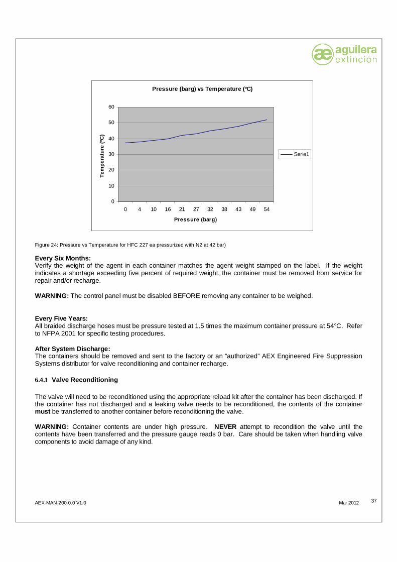
Every Three Months: Check the pressure gauge on each container. The nominal pressure should be approximately 25 bar at 21°C; however, the pressure will vary with temperature. In the range of 10oC to 32oC the difference is approximately 0.2 bar per degree. If the pressure loss indicated exceeds ten percent of the nominal pressure, check the container for leaks and repair as necessary. Temperature (ºC) Pressure (barg)
0 37 4 38
10 39 16 40 21 42 27 43 32 45 38 46 43 48 49 50 54 52
Table 10: Pressure vs Temperature for HFC 227 ea (pressurized with N2 at 42 bar)
AEX-MAN-200-0.0 V1.0 Mar 2012
37
Pressure (barg) vs Temperature (ºC)
0
10
20
30
40
50
60
0 4 10 16 21 27 32 38 43 49 54
Pressure (barg)
Tem
pera
ture
(ºC
)
Serie1
Figure 24: Pressure vs Temperature for HFC 227 ea pressurized with N2 at 42 bar) Every Six Months: Verify the weight of the agent in each container matches the agent weight stamped on the label. If the weight indicates a shortage exceeding five percent of required weight, the container must be removed from service for repair and/or recharge. WARNING: The control panel must be disabled BEFORE removing any container to be weighed. Every Five Years: All braided discharge hoses must be pressure tested at 1.5 times the maximum container pressure at 54°C. Refer to NFPA 2001 for specific testing procedures. After System Discharge: The containers should be removed and sent to the factory or an “authorized” AEX Engineered Fire Suppression Systems distributor for valve reconditioning and container recharge. 6.4.1 Valve Reconditioning The valve will need to be reconditioned using the appropriate reload kit after the container has been discharged. If the container has not discharged and a leaking valve needs to be reconditioned, the contents of the container must be transferred to another container before reconditioning the valve. WARNING: Container contents are under high pressure. NEVER attempt to recondition the valve until the contents have been transferred and the pressure gauge reads 0 bar. Care should be taken when handling valve components to avoid damage of any kind.
AEX-MAN-200-0.0 V1.0 Mar 2012
38
6.5 REMOTE PNEUMATIC ACTUATION Systems that utilize a remote nitrogen actuator for system release must adhere to the following maintenance 6.6 CONTAINER TEST AND INSPECTION Containers shall be subjected to periodical tests as required by the relevant national standard. This may or may not include hydrostatic pressure testing after a system discharge – or for systems


SU PUNTO DE ASISTENCIA Y SUMINISTRO MAS PRÓXIMO
SEDE CENTRAL C/ Julián Camarillo, 26 – 2ª Planta – 28037 Madrid – Tel: 91 754 55 11 – Fax: 91 754 50 98
FACTORÍA DE TRATAMIENTO DE GASES
Av. Alfonso Peña Boeuf, 6. Pol. Ind. Fin de Semana – 28022 Madrid – Tel: 91 754 55 11 – Fax: 91 329 58 20
DELEGACIÓN NORDESTE C/ Rafael de Casanovas, 7 y 9.- Sant Adrià de Besòs – 08930 Barcelona
Tel: 93 381 08 04 – Fax: 93 381 07 58
DELEGACIÓN LEVANTE Avda. Mediterránea 46 – San Juan de Enova – 46669 Valencia
Tel: 628 92 70 56 – Fax: 91 754 50 98
DELEGACIÓN NOROESTE C/ José Luis Bugallal Marchesi, 9– 15008 A Coruña – Tel: 98 114 02 42 – Fax: 98 114 24 62
DELEGACIÓN SUR
C/ Industria, 5 –Edificio Metropol 3, 3ª Planta, Mod.17. P.I.S.A.- 41927 Mairena del Aljarafe, Sevilla Tel: 95 465 65 88 – Fax: 95 465 71 71
DELEGACIÓN CANARIAS
C/ Sao Paulo, 17. Pol. Ind. El Sebadal – 35008 Las Palmas de Gran Canarias – Tel: 928 24 45 80 – Fax: 928 24 65 72
www.aguilera.es e-mail: [email protected]