HFC-152a SECONDARY LOOP VEHICLE A/C SYSTEMS has a 100-year IPCC Second Assessment Report GWP of 140...
40
Report of the 14–15 August 2007 U.S. EPA Workshop on HFC-152a SECONDARY LOOP VEHICLE A/C SYSTEMS OCTOBER 30, 2007
Transcript of HFC-152a SECONDARY LOOP VEHICLE A/C SYSTEMS has a 100-year IPCC Second Assessment Report GWP of 140...
Report of the 14–15 August 2007 U.S. EPA Workshop on
HFC-152a SECONDARY LOOP
VEHICLE A/C SYSTEMS
OCTOBER 30, 2007

Dr. Alberto Ayala, California Air Resources Board;
Dr. Stephen O. Andersen, Director of Strategic Climate Projects, US EPA Climate Protection Partnerships
Division;
Ward Atkinson, Chair, Interior Climate Control Committee, Society of Automotive Engineers, and
President, Sun Test Engineering;
James Baker, Senior Staff Research Scientist, Delphi Corporation;
Lisa Bendixen, Vice President, ICF International;
Dr. Neal Blackwell, Senior Project Engineer, US Army;
David D. Doniger, Climate Center Policy Director, Natural Resources Defense Council;
Dave Godwin, Environmental Engineer, Stratospheric Protection Division, US EPA;
Gary Hansen, Vice President, Red Dot;
Elvis Hoffpauir, President, Mobile Air Conditioning Society Worldwide;
Paul Hughes, Low Emission Vehicle Manager, California Air Resources Board;
Dr. Carloandrea Malvicino, Head, Thermal Systems Department, Centro Ricerche Fiat;
Nha Nguyen, International Policy and Harmonization, US National Highway Traffic Safety Administration;
Sally Rand, Director High GWP Voluntary Industry Partnerships, Climate Change Division, US EPA;
Alberto N. Reginaldo, MAC Principal Engineer, Toyota Technical Center;
John Rugh, Senior Engineer, MAC Fuel Use Reduction Task, US National Renewable Energy
Laboratory;
Fred Sciance, Manager of Global Climate Issues, General Motors;
Leland Shields, Member, SAE Fire Safety Committee and President, Leland E. Shields, Inc.;
Scott Stone, Senior Attorney, Institute for Government and Sustainable Development; and
Kristen Taddonio, Manager, Strategic Climate Projects, US EPA; and
Mark Zima, Engineering Manager, Delphi Corporation.
Peer reviewed by Hagen Deyhle (Porsche), Thomas Drees (Volkswagen), Hans Fernqvist (Volvo),
Reynaldo Forte (EPA), William Hill (General Motors), James Jetter (EPA), Stephen Lepper (Ford), Jean
Lupinacci (EPA), John Meyer (Visteon), Roberto Monforte (Fiat), Erhard Moser (BMW), Wolfgang Rilling
(DaimlerChrysler), Paul Risch (Audi), and Helen Tope (Energy International Australia).

Table of Contents
1. Executive Summary ................................................................................................................................... 1
1.1. Key Findings—Health and Safety, Climate, and Air Quality Benefits .............................................. 3
1.2. Key Findings—Flammability Risk ....................................................................................................... 4
1.3. Key Findings—Public and Private Safety Regulations and Standards ............................................ 5
1.4. Key Findings—Service......................................................................................................................... 5
2. Annotated Review of HFC-152a Commercialization ............................................................................ 5
3. Climate and Air Quality Benefits of HFC-152a MACs .......................................................................... 6
3.1. Energy Efficiency Is Key to Good LCCP ............................................................................................ 7
3.2. HFC-152a Is an Efficient, Low-GWP Option ...................................................................................... 7
3.3. Comparing the Climate Impacts of Alternative MAC Systems With Green-MAC-LCCP©.............. 8
3.3.1. How LCCP Is Calculated for MACs ........................................................................................... 8
3.3.2. How to Use the Model ................................................................................................................ 9
3.3.3. Preliminary Results ..................................................................................................................... 9
4. Flammability Risk of HFC-152a.............................................................................................................. 10
5. Mitigation Strategy to Reduce Flammability Risk .............................................................................. 11
5.1. Mitigation Adequacy........................................................................................................................... 11
5.1.1. Fault Tree Findings From HFC-152a Risk Assessments....................................................... 11
5.2. Safety-Mitigated Secondary Loop HFC-152a Systems Relative to Other Vehicle-Related Risks .......................................................................................... 14
5.2.1. Compared to Vehicle Fuel Flammability Risks ....................................................................... 14
5.3. Importance of SAE Standards to A/C Safety ................................................................................... 15
6. Safety and Training Measures for MAC Service ................................................................................. 16
6.1. Unique Fittings and Labels, and Service Equipment and Tools ..................................................... 16
6.2. Service Technician Safety Precautions ............................................................................................ 17
7. Model State Legislation to Safely Allow HFC-152a Systems............................................................ 17
8. Appendices................................................................................................................................................ 21
8.1. SAE New and Revised HFC-152a Documents................................................................................ 21
8.1.1. Design Requirements ............................................................................................................... 21
8.1.2. Service Sector ........................................................................................................................... 21
8.2. HFC-152a Chemical and Physical Properties.................................................................................. 22
8.3. HFC-152a Flammability Properties................................................................................................... 24
8.4. Flammable Refrigerant Fault Tree Analysis ..................................................................................... 25
8.5. Annotated CalTech Glossary on Explosion Dynamics .................................................................... 30


1
1. Executive Summary
The Challenge and Approach, Tiger Team Members, Consensus Process, Critical Technical Background.
All passenger vehicles and light trucks manufactured with air conditioning (A/C) worldwide currently use refrigerant hydrofluorocarbon 134a (HFC-134a) in direct expansion systems.
European Union (EU) regulations require air-conditioned vehicles sold in EU countries to use refrigerants with global warming potentials (GWP) less than 150 beginning in 2011 for new type vehicles and in all vehicles by 2017. GWP is an index comparing the climate impact of an emission of a greenhouse gas relative to that of emitting the same mass of carbon dioxide (CO2).
1 The calculated GWP of any particular substance depends on the changing condition of the atmosphere, evolving carbon sinks, and updated laboratory measurements. Because the GWP values can change over time, policymakers specify the values from a particular referenced report for purposes of regulations. For the U.S. greenhouse gas inventory, the United Nations Framework Convention on Climate Change, and the Kyoto Protocol, the GWP is fixed permanently at the value in the Intergovernmental Panel on Climate Chance (IPCC) Second Assessment Report (1996).2
The predominant refrigerant in today’s A/C systems, HFC-134a, has a 100-year IPCC Second Assessment Report GWP of 1300 and is therefore being phased out under the EU legislation described above. HFC-152a has a 100-year IPCC Second Assessment Report GWP of 140 and is therefore allowed by the EU regulations. Environmental authorities in California and 12 other states are considering similar regulations that may soon control or prohibit HFC-134a. The EU regulation does not take into account indirect emissions of greenhouse gases from fuel consumption required to power and transport the additional weight of A/C systems.
Vehicle manufacturers prefer a single global refrigerant that satisfies regulatory authorities in all global markets.
Systems satisfying the EU regulation using CO2 (CO2 – R-744), and HFC-152a (HFC-152a – R-152a) have been engineered and tested, and component and systems suppliers have announced their commercial availability. BMW and other German vehicle manufacturers have announced that they plan to offer CO2 systems in the EU. Hydrocarbons (HCs, e.g. propane – R-290) refrigerants are commercially available and widely used outside North America in small refrigerators, refrigerated display cases, and in other applications, and would technically satisfy the EU regulation. However, no automotive supplier recommends or offers HC systems for vehicles. In addition, the industry is reviewing other recently announced synthetic-blend refrigerants (typically with at least one HFC ingredient) that would meet the GWP 150 limit.
“Direct expansion” or “primary loop” A/C systems place the condenser in a location of high air flow directly behind the vehicle front grill inlet to reject heat and place the refrigerant-to-air in the air distribution system. The evaporator is inside the passenger or engine compartment providing cool air to the passengers (see figure 1). Breach of components in the dash would discharge refrigerant directly into the passenger compartment. Breach of under-hood components would discharge refrigerant to the engine compartment. The average charge size of refrigerant for a

2
direct expansion A/C system is as little as 500 grams, with a typical charge of 650 to 800 grams for single evaporator systems. A portion of refrigerant charge may remain in a breached system dissolved in the approximately 100–150 grams of lubricant (typically a polyaklylene glycol (PAG) oil) and coating components.
Secondary loop A/C systems locate a refrigerant-to-liquid evaporator (called a chiller) in the engine compartment, rather than an evaporator in the air distribution system. The refrigerant chills coolant (likely an antifreeze/water mix) that is circulated by an electric pump to a heat exchanger that cools the air in the passenger compartment (see figure 2). The secondary loop A/C system prevents the refrigerant from entering the air distribution system and the passenger compartment in the event of a leak or collision.
Figure 1: Direct expansion A/C system Figure 2: Secondary loop A/C system
The length of the refrigerant plumbing (tubing/hose) may be shortened depending on the chiller location, which, together with the properties of R-152a, significantly reduces the system refrigerant charge. Because all components containing refrigerant are located in the engine compartment, air flow around and under the engine dissipates any refrigerant leaks without significant infiltration into the passenger compartment. The average charge size of refrigerant for a secondary loop A/C system can be about half that of a direct expansion A/C system—about 250 or 400 grams for vehicles that would otherwise use a 500 or 600 gram direct expansion system, respectively.
Except for the chiller (replacing the conventional evaporator in the direct expansion A/C system), the refrigerant circuit of the secondary loop system utilizes components similar to HFC-134a systems. HFC-152a systems have operating system parameters, such as pressures, comparable to HFC-134a systems.
Use of the chilled water/antifreeze mix in secondary loop systems also eliminates the necessity of large refrigerant charges for vehicles currently having two or more refrigerant evaporators (SUVs, passenger vans, high-end passenger vehicles, limousines, and advanced hybrid vehicles requiring battery and inverter cooling).

3
The U.S. Environmental Protection Agency (EPA) has proposed that HFC-152a refrigerant be listed under the Significant New Alternatives Policy (SNAP) Program as acceptable for new vehicle A/C systems, as long as systems are designed to avoid, in the event of a collision or equipment failure, concentrations in the passenger cabin free space above the 3.7% lower flammable limit (LFL) for more than 15 seconds. EPA also has proposed to list R-744 (CO2) systems as acceptable under SNAP with proper safety features to avoid unsafe CO2 concentrations in the passenger cabin.
1.1 Key Findings—Health and Safety, Climate, and Air Quality Benefits
HFC-152a has comparable toxicity to the current refrigerant, HFC-134a. Both have a 1,000 parts per million (ppm) Acceptable Exposure Limit (AEL) and Workplace Environmental Exposure Limit (WEEL) and no Short Term Exposure Limits (STEL). Neither has a toxicity concern at the concentrations that can be experienced in the event of a full discharge into the passenger compartment.
Toxicological Test HFC-134a HFC-152a
Acute (LC50) (ppm) >500,000 383,000
Cardiac sensitivity – no effect level (ppm)
50,000 50,000
Worker exposure limit (ppm)
1,000 1,000
28-day NOAEC (ppm) 50,000 100,000 (14-day)
90-day NOAEC 50,000 25,000 (2-year)
Developmental toxicity Effect threshold 40,000 Negative
Genotoxicity Negative Negative
(Ames test only)
Aquatic toxicity (mg/L) 450 No data
HFC-152a has a 100-year IPCC Second Assessment Report GWP of 140 and an atmospheric lifetime of 1.45 years, whereas HFC-134a has a 100-year IPCC Second Assessment Report GWP of 1,300 and an atmospheric lifetime of 14.6 years (IPCC, 1995).
Life-Cycle Climate Performance (LCCP) is the integrated estimate of total greenhouse gas emissions resulting from direct refrigerant emissions and indirect fuel use. A computerized LCCP model has been developed by a partnership headed by General Motors and including

4
EPA, the Japan Automobile Manufacturers’ Association (JAMA), the U.S. Department of Energy’s (DoE) National Renewable Energy Laboratory (NREL), and other partners.
NREL has calculated a potential 21% reduction in A/C fuel use for an HFC-152a secondary loop system on an Opel Astra that incorporates capacity control to take full advantage of the higher thermal ballast available in secondary loop systems. An added benefit of a secondary loop system is that it enables controls that exploit vehicle inertia to cool the secondary loop fluid and components during deceleration or when the engine is operating at high energy efficiency (and lowest tailpipe emissions). In addition, the secondary loop allows extended idle stop operation in hot weather by drawing on the thermal ballast of that cooled secondary fluid and components. Idle stop requires additional components beyond those of the secondary loop A/C system. These secondary loop HFC-152a systems would increase the fuel efficiency of all vehicles, with the greatest percentile gains by the most efficient vehicles and the least percentile gains by the least efficient vehicles, where A/C fuel use is a smaller part of total fuel consumption.
NREL and EPA estimate that secondary loop HFC-152a systems with capacity control and extended idle stop vehicle operation can save up to 2.6 billion gallons of fuel per year for the United States alone if implemented in every vehicle, eliminating 23.2 million metric tons (MMT) CO2 equivalent (CO2eq) per year in greenhouse gases.
At $3.00/gallon, average fuel savings of 11.4 gallons/year/vehicle, and $100 to $150 savings from one less system recharge during the useful life of the vehicle as a result of longer refrigerant containment prior to service, the added cost of secondary loop HFC-152a systems in new vehicles can be rapidly paid back in hot climates. Addition of a fluid pump and cooler may add to warranty costs.
HFC-152a is a low-cost chemical that no longer has manufacturing patent restrictions and is used in hundreds of household products today, including Dust-off® pressurized blowers, hairspray, deodorant, and other consumer products.
1.2 Key Findings—Flammability Risk
While some tests have shown that HFC-152a has limited flammability and is difficult to ignite when released into engine compartments, it still requires risk mitigation such as a secondary loop or active detection and safe discharge if used as a refrigerant in vehicle A/C systems. HFC-152a therefore is not suitable for use in vehicles not designed for flammable refrigerants. Current CFC-12 or HFC-134a direct expansion systems cannot be safely retrofitted for flammable refrigerants. In Europe the updated EN 378 standard developed for stationary A/C systems currently bans refrigerants considered flammable in direct expansion systems but allows them in building systems with secondary loops.
Direct expansion HFC-152a systems with refrigerant-containing components within the passenger compartment would require active safety systems that can detect and respond with high reliability to any leakage of refrigerant into the passenger compartment and require additional safety mitigation for risk of leakage into the engine compartment from collision damage or component failure.
Secondary loop HFC-152a systems eliminate the risk of refrigerant leakage to the passenger compartment and explicitly satisfy the EPA-proposed criteria that refrigerant concentrations in the passenger cabin free space not exceed 3.7% for more than 15 seconds.

5
HFC-152a systems would contribute little to overall vehicle fire risk if components containing HFC-152a are located within the engine compartment and are designed to avoid conditions where flammable mixtures can develop adjacent to potential sources of ignition.
Properly designed HFC-152a secondary loop systems would include incremental flammability risk similar to commonly accepted automotive design choices affecting fuel choice and the quantities, containment, and location of under-hood flammable materials. These risks are manageable and reducible by modest design changes.
1.3 Key Findings—Public and Private Safety Regulations and Standards
Mobile A/C systems are federally regulated by EPA and the U.S. Department of Transportation (DoT), and are subject to Society of Automotive Engineers (SAE) standards. EPA and several states cite SAE-recommended practices and standards in regulations designed to ensure refrigerant safety and environmental performance.
The Mobile Air Conditioning Society (MACS) Worldwide is developing new training programs for servicing HFC-152a mobile A/C systems that will be based on new SAE standards, including a proposed standard that would require certification to work on HFC-152a systems.
International cooperation of authorities from governments, companies, and nongovernmental organizations (NGOs) on introduction of HFC-152a and other systems can help ensure uniformity and acceptability in fire risk mitigation and efficiency in expenditure of resources for design, development, testing, service training, and refrigerant supply. Cooperation can also promote the choice of system designs and refrigerants that provide superior life-cycle climate performance.
Development of new SAE standards is underway to document proper design of refrigerant systems, service equipment, and service procedures for handling of R-152a, and to ensure continued refrigerant safety and performance. The standards will be developed in the coming months and should be referenced by new government regulations.
1.4 Key Findings—Service
Member surveys by MACS indicate that flammable substances are already routinely handled in servicing shops, and that HFC-152a would not be considered a significant addition to normal operating risks that are inherently a part of any automotive service job, as long as service personnel are aware that a flammable refrigerant is in use. The design of commercially manufactured HFC-152a systems will include development of service equipment and procedures to minimize flammability risk.
2. Annotated Review of HFC-152a Commercialization
Late 1980s: EPA investigated flammable refrigerants—including HCs, HFC-152a, and dimethylether (DME).
Early 1990s: DoE investigated flammable refrigerants and published the definitive study by A.D. Little.
2002: SAE’s Alternate Refrigerants Cooperative Research Program (ARCRP) evaluated a direct expansion system using HC refrigerant (R290).

6
2003 Secondary loop systems with HFC-152a were demonstrated at the SAE Phoenix Alternate Refrigerant Symposium.
2004: HFC-152a studies were conducted during the SAE Alternate Refrigerants Cooperative Research Program. Also, Red Dot Corporation developed and demonstrated a roof top R-152a system. Field trials are underway in Australia in cooperation with EPA, the Australia Commonwealth EPA, the Victoria EPA, the Australia Coal Council and other trade, environmental, and industry advisers.
2007: Secondary loop systems with HFC-152a were demonstrated at the SAE Phoenix Alternate Refrigerant Symposium and the Second European Workshop on Mobile Air Conditioning (Orbassano, Italy).
3. Climate and Air Quality Benefits of HFC-152a MACs
LCCP is the integrated estimate of total greenhouse gas emissions attributable to a particular technology over its lifetime. Worldwide, it is considered the most comprehensive way to calculate climate impacts. For mobile A/C (MAC) systems, LCCP is the sum of direct refrigerant emissions and indirect emissions that result from the energy consumption due to MAC manufacturing, A/C operation, and end-of-life processing. The many direct and indirect factors that contribute to MAC greenhouse gas emissions are listed in box 1 and are illustrated by the figure below.
Figure 3: Life-Cycle Greenhouse Gas Emissions From MAC systems. Credit: Stella Papasavva, General Motors
C
O 2 C
O 2 C
O 2
Transportati
on Min
e
C
O 2 C
O 2
Refrigerant MANUFACTURING
Transportation Indirect Emissions
End use of chemicals
Direct Emissions
CO2
HFC
Atmospheric degradation products +
Recycling
HCOF COF 2 COFCl
CO2
Breakdown
CO2
TFA HF
C
Refrigerant USE
Refrigerant End-of-Life
Raw Materials
HF
C
HF
C

7
3.1 Energy Efficiency Is Key to Good LCCP
Energy efficiency is critical to good life-cycle climate performance—an alternative MAC system should have low indirect emissions from fuel use and low direct refrigerant emissions. A switch to an alternative refrigerant would be counterproductive if it resulted in an increase in tailpipe greenhouse gas emissions greater than the reduction in greenhouse gas refrigerants. It is especially important that the alternative refrigerant selected worldwide be energy efficient because throughout the world, A/C energy use is currently unregulated. Energy efficiency is not part of fuel efficiency standards and is not yet fully accounted on fuel mileage labeling.
A/C is responsible for more than 5% of all motor fuel consumption each year in the United States and for up to 30% of fuel consumed each year in the hottest, most humid climates.3 For example, MAC fuel use in India is estimated at up to 19.4% of total passenger vehicle consumption.4 In the United States, A/C fuel use makes up the majority of greenhouse gas emissions that result from MAC systems. In the United States alone, vehicle air conditioners consume 7 billion gallons of gasoline every year, equivalent to over 61 MMT of CO2.
5 (By comparison, HFC-134a refrigerant MAC emissions in the United States are equivalent to approximately 53 MMT of CO2.
6) The impact of vehicle A/C will increase significantly in the future because it is quickly becoming a standard feature on vehicles sold throughout the world. A/C is already standard in developed countries, and it is quickly becoming standard in Brazil, China, India, and all other developing countries with high growth in motor vehicle ownership.
Box 1: Direct and indirect MACA/C greenhouse gas emissions.
Direct Emissions result from the direct leaks of the refrigerant into the atmosphere and are an aggregate of the following leakage categories:
Regular emissions, which refer to the refrigerant leaks or permeation from the A/C system during operation.
Irregular emissions due to accidents, stone hits, product defects, etc.
Service emissions from garages during maintenance and repair. These items are newly estimated based on the recently completed SAE Improved Mobile Air Conditioning (SAE I-MAC) Study. The results are still somewhat dependent on the skills and practices of the service technicians.
End-of-life (EOL) emissions from recovery of refrigerant at the vehicle’s EOL.
Leakage during refrigerant production and transportation.
Atmospheric reaction products associated with atmospheric breakdown of the refrigerants.
Indirect Emissions result from energy consumption due to MAC manufacturing, operation, and EOL, and is an aggregate of the following CO2 emissions categories:
Manufacturing and EOL recycling processes of various alternative refrigerants.
Manufacturing and EOL recovery processes of each component of the A/C system.
Fuel use emissions associated with A/C operation (such as those associated with operation of the compressor and engine cooling fan) during the lifetime of the vehicle.
Emissions associated with additional fuel consumption due to the A/C mass transportation onboard the vehicle throughout the lifetime of the vehicle.

8
3.2 HFC-152a Is an Efficient, Low-GWP Option
HFC-152a secondary loop A/C systems offer attractive fuel economy benefits in addition to large reductions in direct refrigerant emissions. NREL has calculated a potential 21% reduction in A/C fuel use for an HFC-152a secondary loop system that incorporates capacity control to take full advantage of the higher thermal ballast available in secondary loop systems.7 An added benefit of a secondary loop system is that it enables controls that exploit vehicle inertia and allow extended idle stop operation in hot weather. Idle stop requires additional components beyond those of the secondary loop A/C system.
NREL and EPA estimate that secondary loop HFC-152a systems with capacity control and extended idle stop vehicle operation can save up to 2.6 billion gallons of fuel per year for the United States alone when implemented in every vehicle, eliminating 23.2 MMT CO2eq/year in greenhouse gas emissions. At $3.00/gallon, average fuel savings of 11.4 gallons/year/vehicle, and $150 savings from longer refrigerant containment prior to service, the added cost of secondary loop HFC-152a systems in new vehicles can be rapidly paid back in hot climates.
3.3 Comparing the Climate Impacts of Alternative MAC Systems With Green-MAC-LCCP©
Past efforts to compare alternative MAC systems have been thwarted by the lack of a single, globally accepted method to calculate MAC greenhouse gas emissions. Different researchers used different assumptions and methodologies, resulting in wide variation in calculations. To enable an “apples-to-apples” comparison, General Motors, JAMA, SAE, and EPA teamed up to develop a common methodology to calculate the life-cycle climate performance of MACs with different refrigerants. The effort was successful: The Global Refrigerants Energy & Environmental Mobile Air Conditioning Lifecycle Climate Change Performance (GREEN-MAC-LCCP)© model is now available from the partnership and is online (www.epa.gov/cppd/mac) in cooperation with the United Nations Environment Programme Division of Technology, Industry, and Economics (DTIE). This tool lets stakeholders compare choices in a transparent manner. It is globally peer reviewed and globally accepted, and is now the gold standard in LCCP credibility.
3.3.1. How LCCP Is Calculated for MACs
LCCP provides a holistic approach in estimating all greenhouse gas contributions emitted during the lifetime of any MAC system, regardless of refrigerant. The direct and indirect components of the model are explained as follows:
Direct Emissions result from the direct leaks of the refrigerant into the atmosphere and are evaluated based on the GWP of each chemical and its mass emitted into the atmosphere. The direct emissions are expressed in terms of CO2eq emissions and calculated based on the GWP of the refrigerant (see box 1 above for an elaboration).
Indirect Emissions result from the energy consumption due to MAC manufacturing, operation, and EOL, and is reported in terms of CO2eq emissions, considering the carbon content of the fuel utilized in each process and during vehicle operation (see box 1 above).

9
3.3.2. How to Use the Model
GREEN-MAC-LCCP© consists of many interlinked spreadsheets of data required to run the model. Most of the input data are fixed based on the harmonization process. This prevents tampering with the model and makes sure that comparisons are genuine. Only a small amount of input data is required to run the model. For each global alternative refrigerant, the following information is required:
Component mass
Refrigerant mass and GWP values
Leakage rates
Coefficient of Performance (COP) and Qe data obtained from bench or vehicle tests
The model output provides the LCCP (in terms of CO2eq emissions) of any global alternative refrigerant.
3.3.3. Preliminary Results
The GREEN-MAC-LCCP© model has been used to calculate the LCCP of direct-expansion systems with R-134a, improved R-134a, R-152a, R-744, and R-744 “with Orifice.”8 Results are presented in the graph on the next page. COP and Qe data for an optimized secondary loop HFC-152a system were not available at the time the model was run. The Mobile Air Conditioning Climate Protection Partnership is currently obtaining the information necessary to run the GREEN-MAC-LCCP© model on secondary loop HFC-152a MACs in order to compare them with other global alternatives.
LCCP CO2-Equivalent Emissions during Vehicle's Lifetime
0
5,000
10,000
15,000
20,000
25,000
Ph
oe
nix
Ho
usto
n
Bo
sto
n
Mia
mi
Fra
nkfu
rt
Ath
en
s
To
kyo
Ka
go
sh
ima
Sapporo
Bangalo
re
Bo
mb
ay
New
Delh
i
Syd
ne
y
Be
ijin
g
Sh
an
gh
ai
CO
2-E
qu
ivale
nt
Em
issio
ns (
kg
)
R-134a R-152a R-744 R-744_OTB R-134a-I-MAC

10
4. Flammability Risk of HFC-152a
Vehicle fires are a small proportion of the total of vehicle fatal injuries and property damage (see table 1). One-tenth of one percent (0.1%) of crashes result in fire, 9 and most of the 4% of fatalities in vehicles with fires are due to crash-related trauma.10 In addition, it can be estimated that approximately 0.1% of registered vehicles are subject to fire in a given year, the vast majority of which are noncollision fires.11 Still, fires are perceived to be disturbing in a manner that affords them greater vehicle safety attention than their numbers would suggest.
For further context, it should be understood that the vast majority of vehicle fire-related injuries and fatalities occur in crashes, and because fires are usually slow events (relative to the time it takes to exit a vehicle), fatalities occur primarily in cases of incapacitation and entrapment. Losses due to property damage are of greater concern in the heavy vehicle industry, where the vehicles themselves are more costly. These vehicles more commonly have manufacturer options for fire detection and suppression systems.
Table 1: US Vehicle Fire Statistics12
Condition Number Scale
Fatality and Fire (2004) 1,077 3.8% of Fatals
Crash and Fire (2004) 10,739 0.1% of Crashes
Fires (~98% noncrash, 2001)
257,000 $1.064 Billion
As a result of the concerns about vehicle fires, research, design, standards, and regulation continue to foster improvements in vehicle fire safety. In recent years, the US National Highway Traffic Safety Administration (NHTSA) has increased the stringency of FMVSS 301, regulating leakage of gasoline and diesel fuel in collisions. NHTSA is also evaluating improvements to FMVSS 302 (regulating the flammability of vehicle interior components). In addition, the National Fire Protection Association is considering a proposal for a standard designed to increase the time for fire propagation to the vehicle interior. Each of these (changes and proposals) can be taken as representative of the nature of public concern and the direction of intended improvements.
At the same time, with fires a small percentage of the vehicle safety problem, there is cause for moderation as well. Improvements in vehicle fire safety may be advanced, for example, by increasing the use of fire-retardant materials which in themselves may have health risks worthy of deliberation. It is therefore prudent and necessary to consider tradeoffs inherent in designs for fire safety with other health and safety factors.13 It is in this context that consideration of HFC-152a must be considered: While HFC-152a may have an additional non-zero risk of fire

11
(as compared to the overall existing non-zero risk), it s use may also provide benefits that far outweigh those risks.
Fire safety research related to HFC-152a usage in MACs with secondary loop systems has been initiated, and some studies have been published. Additional studies have been conducted by manufacturers and are considered proprietary at this time. At least one laboratory study of the HFC-152a flammability properties concluded that it had potential for explosivity14; a full-scale vehicle test showed at least moderate flammability and explosivity.15 The potential flammability of the material warrants careful consideration as to its impact on such important fire-safety issues as increase in under-hood fuel load; propagation time to the interior; explosivity in crashes, enclosed areas, and during service operations; safety of fire service personnel when fighting vehicle fires; and specific risks in aging vehicles. But the precise flammability characteristics of the material are not in and of themselves the critical factor for vehicle safety; rather, vehicle safety is achieved through the process of risk assessment, mitigation, design, and standard setting. The EU/EPA project to remove barriers to the use of all refrigerants satisfying the GWP 150 EC regulation advocates SAE design, emissions, and service standards to achieve these objectives.
While hydrogen is an undoubtedly explosive gas, its energy and environmental benefits are so great that enormous research, design, and standard-setting efforts are being expended on its development in automotive applications.16 Just as in hydrogen fuel development, the safe development of HFC-152a for MAC can be fostered through appropriate identification of risks; testing of designs, components, material properties, and full-scale vehicles; mitigation of identified risks; and setting appropriate standards (See Appendix VIII-A – SAE New and Revised HFC-152a Documents).
5. Mitigation Strategy to Reduce Flammability Risk
5.1. Mitigation Adequacy 5.1.1. Fault Tree Findings From HFC-152a Risk Assessments
EPA and DoE risk assessments conducted in 1991 and 2006 found that the risks of HFC-152a in direct expansion MAC systems were small and could be mitigated with various engineering strategies. The secondary loop A/C system was recommended as one of the most reliable and comprehensive engineering strategies. Consequently, the risk for a direct expansion system are not what would be expected for a secondary loop HFC-152a A/C system, which carries significantly lower risk.
a) EPA Risk Assessment (2006)
An EPA risk assessment published in 2006 examined the passenger compartment risks of primary loop direct expansion HFC-152a systems. The fault tree analysis focused on passenger and service technician safety. The conclusion of the EPA risk assessment was that there would be up to “50 potential events with ignition in the passenger compartment each year if the entire fleet of passenger vehicles were to use HFC-152a” in direct expansion systems with comparable charge size and there was no mitigation for safety.17 The analysis predicted that HFC-152a ignition in the passenger compartment would not necessarily lead to injury in all
12
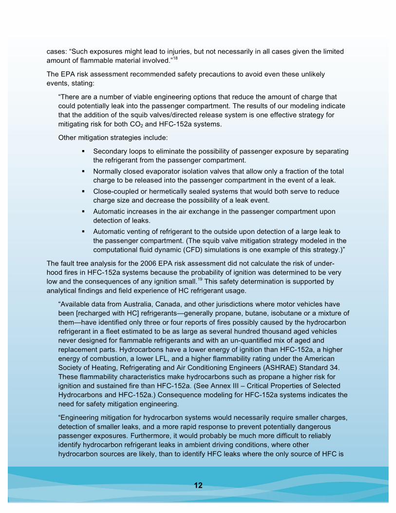
cases: “Such exposures might lead to injuries, but not necessarily in all cases given the limited amount of flammable material involved.”18
The EPA risk assessment recommended safety precautions to avoid even these unlikely events, stating:
“There are a number of viable engineering options that reduce the amount of charge that could potentially leak into the passenger compartment. The results of our modeling indicate that the addition of the squib valves/directed release system is one effective strategy for mitigating risk for both CO2 and HFC-152a systems.
Other mitigation strategies include:
Secondary loops to eliminate the possibility of passenger exposure by separating the refrigerant from the passenger compartment.
Normally closed evaporator isolation valves that allow only a fraction of the total charge to be released into the passenger compartment in the event of a leak.
Close-coupled or hermetically sealed systems that would both serve to reduce charge size and decrease the possibility of a leak event.
Automatic increases in the air exchange in the passenger compartment upon detection of leaks.
Automatic venting of refrigerant to the outside upon detection of a large leak to the passenger compartment. (The squib valve mitigation strategy modeled in the computational fluid dynamic (CFD) simulations is one example of this strategy.)”
The fault tree analysis for the 2006 EPA risk assessment did not calculate the risk of under-hood fires in HFC-152a systems because the probability of ignition was determined to be very low and the consequences of any ignition small.19 This safety determination is supported by analytical findings and field experience of HC refrigerant usage.
“Available data from Australia, Canada, and other jurisdictions where motor vehicles have been [recharged with HC] refrigerants—generally propane, butane, isobutane or a mixture of them—have identified only three or four reports of fires possibly caused by the hydrocarbon refrigerant in a fleet estimated to be as large as several hundred thousand aged vehicles never designed for flammable refrigerants and with an un-quantified mix of aged and replacement parts. Hydrocarbons have a lower energy of ignition than HFC-152a, a higher energy of combustion, a lower LFL, and a higher flammability rating under the American Society of Heating, Refrigerating and Air Conditioning Engineers (ASHRAE) Standard 34. These flammability characteristics make hydrocarbons such as propane a higher risk for ignition and sustained fire than HFC-152a. (See Annex III – Critical Properties of Selected Hydrocarbons and HFC-152a.) Consequence modeling for HFC-152a systems indicates the need for safety mitigation engineering.
“Engineering mitigation for hydrocarbon systems would necessarily require smaller charges, detection of smaller leaks, and a more rapid response to prevent potentially dangerous passenger exposures. Furthermore, it would probably be much more difficult to reliably identify hydrocarbon refrigerant leaks in ambient driving conditions, where other hydrocarbon sources are likely, than to identify HFC leaks where the only source of HFC is

13
the air conditioning system. EPA has not identified a mitigation strategy that would allow for the safe use of hydrocarbon refrigerants, and so far, hydrocarbon mobile air conditioning advocates have not presented technical evidence that hydrocarbons can be safely applied in motor vehicles.
“EPA conducted a global search of available data, including insurance and public media reports, and did not find any significant reports of fire or ignition from hydrocarbon refrigerants in MAC systems. The low number of fire events is further supported by the absence of known claims paid by refrigerant manufacturers or insurers and the lack of additional insurance premiums for HC use. In addition, as discussed above, HFC-152a has a higher flammability limit than hydrocarbons which provides an extra margin of safety.”
b) Department of Energy (DoE Risk Assessment (1991)
A comprehensive DoE (Office of Transportation Technology) risk assessment conducted in 1991 examined the risks of HFC-152a and two other flammable refrigerants (propane and cyclopropane) in primary loop systems. The fault tree analysis conducted in this study looked at under-hood fire risks along with passenger exposures. It contained event trees for the occupant compartment and engine compartment (see DoE risk assessment). The conclusions of the DoE risk assessment is:
Conclusions “The overall objective of this project was to develop a preliminary evaluation of the potential benefits of using a non-inert refrigerant in automobile air conditioning systems and to assess the increased safety risks associated with this class of working fluids. Three non-inert refrigerants were identified that are readily applicable to normal automobile practice -- 2 near drop-ins, HFC-152a and HC-270 (cyclopropane), and one with higher operating pressures, HC-290 (propane) -- and offer potentially significant environmental and energy efficiency benefits, at little or no additional costs. Flammability is the only hazardous characteristic that was identified for any of these three substances. Preliminary risk analyses indicate that the fire risk associated with these fluids in automobile air conditioning systems is modest, and reducible by modest design changes, in comparison to the general levels of fire, property damage, and injury risk associated with motor vehicle transportation. Overall, the potential benefits are significant relative to the risks, which are manageable, given focused efforts to address the issues raised by the work in this initial phase of the project.”
Potential Benefits “Increased gas mileage, compared to HFC-134a ranging between ½ MPG increase for HFC-152a and propane to 1 MPG increase for cyclopropane, for a typical compact car whose fuel consumption is 27.5 miles per gallon. For such a vehicle driven 15,000 miles per year, with the air conditioning operating one half of the time, a 1 MPG increase in fuel mileage while the air conditioner operates results in an annual saving of approximately 10 gallons of gasoline, reducing annual vehicle operating costs by (US) $12 - $15 (at 1993 gas prices).” At 2007 gas prices the savings are US $25 - $30.
“Non-inert candidates HFC-152a, HC-290, HC-270 have less global warming impact than HFC-134a – approximately equivalent to the reduced carbon dioxide emissions associated

14
with a 1 to 4 MPG higher vehicle fuel efficiency level, depending on the level of refrigerant emissions. All three candidates have zero ozone depletion potential, as does HFC-134a.”
Fire Risk “Based on the results to date the safety of the vehicle occupant with HFC-152a, HC-270, HC-290 in conventionally designed systems will probably be acceptable, subject to further verification by additional field data collection and tests. The estimated injury risk level is .35 injuries per year per million automobiles in service. Among the bases of this estimate is a field survey of evaporator condition in cars that were severely damage by right side “A” pillar impacts. In view of the small size of the data sample (a total of nine such collision damaged cars were examined), a finite rupture probability (5%) was assumed for impacts of this severity level, despite the complete absence of either leakage or physical damage to these evaporators. A larger sampling needs to be taken to provide a solid quantitative basis for estimating the evaporator rupture probability.
“Based on results to date, frontal collisions frequently (in about 1/3 of severe frontal collisions) result in a significant refrigerant leak in conventional system. The range of estimated occurrence of refrigerant ignitions and secondary engine compartment fires is high enough to be of concern, but there is considerable uncertainty about the occurrence of ignition sources.
“The modest set of design modifications to conventional automobile air conditioning systems described in Section 5-1 should result in a reduction of collision and non-inert refrigerant related fires to less than one engine compartment fire per year per million vehicles. This is less than one percent of the number associated with collision fires, and a negligible fraction of total vehicle fires (currently, about one in 20 vehicle fires are caused by collision damage, the remainder being caused by mechanical malfunctions, arson, etc.).
“The estimated rate of fire and injury is so low compared to the existing levels of vehicle fires, vehicle collisions, and resulting injuries and fatalities, that the effect on experience based automobile insurance premiums can be expected to be negligible.
“The risk assessment is based on extensive published data on motor vehicle collision frequency and distribution and frequency of collision damage extent. However, essentially no published data were found relating collision damage location and extent to air conditioning system rupture. Limited data relating these two were developed in this project, consistent with project resources, but more extensive data is needed to improve the statistical significance.”
5.2. Safety-Mitigated Secondary Loop HFC-152a Systems Relative to Other Vehicle-Related Risks
5.2.1. Compared to Vehicle Fuel Flammability Risks
NHTSA’s FMVSS 301 requires manufacturers of passenger vehicles, light trucks, and school buses to mitigate fire risk by strengthening and protecting a vehicle’s fuel system so that, in a crash event, the chances of fuel leakage, and consequently the chances of fire and occupant injury, will be reduced.20

15
FMVSS 301 sets three separate limits on fuel spillage from crash-tested vehicles.
1) It requires that no more than 28 grams (1 ounce) by weight of fuel be spilled during the time period beginning with the start of the impact and ending with the cessation of vehicle motion;
2) It requires that no more than a total of 142 grams (5 ounces) by weight of fuel be spilled during the 5-minute time period beginning with cessation of vehicle motion; and
3) It requires that no more than 28 grams (1 ounce) by weight of fuel be spilled during any 1-minute interval in the 25 minute period beginning with the end of the 5-minute period.
The test procedure prescribes standardized test methods for estimating spillage.
In addition, there is a “rollover” fuel spillage test that requires there be no more than 142 grams (5 ounces) of fuel leakage for the first 5 minutes of testing at each successive 90-degree increment when a vehicle is rotated along its longitudinal axis. Fuel spillage for the remaining test is required not to exceed 28 grams (1 ounce) during any one-minute interval. Because HFC-152a is a pressurized gas, rotating a vehicle has no impact on discharge rate.
Liquid automotive fuel spills often dissipate far slower than gaseous spills. Although liquid fuel spills can have different hazards than an equivalent discharge of a pressurized flammable gas, useful comparisons can be made.
The 170 grams of gasoline allowed to be spilled during the time period beginning with the start of the impact and ending 5 minutes after the cessation of vehicle motion is equivalent to approximately 420 grams of HFC-152a in terms of theoretical heat of combustion (43 MJ/kg for gasoline and 17.4 MJ/kg for HFC-152a).21
The heat of combustion of a 350 gram refrigerant charge of HFC-152a is equal to the heat of combustion of 28 grams of gasoline that is allowed to be leaked between the time of collision and the vehicle coming to rest, and is about 20% of the allowed 142 gram leakage in the first five minutes after the vehicle comes to rest.
A leakage of HFC-152a is less hazardous than the leakage of gasoline with equivalent heat content in HFC-152a systems designed to prevent the accumulation of flammable gaseous mixtures and promote safe dispersion of the gaseous material.
5.3. Importance of SAE Standards to A/C Safety
SAE is completing a full set of standards for HFC-152a and CO2 to ensure vehicle life-cycle safety of systems designed to satisfy the EC regulation prescribing refrigerants with GWP less than 150. However, there are no SAE standards under development at this time for the recently proposed low-GWP global alternative refrigerants (GARs). It will be important to implement design standards such as J-639 and safety standards such as J-2773 and J-2772 for HFC-152a, CO2, or other candidate refrigerants. Designers of HFC-134a systems will want to locate components in well-ventilated spaces where any leaks can quickly disperse. Designers of CO2 systems will want to locate components such that leaks of hot, vaporized lubricant cannot be electrically or thermally ignited. And for both systems it will be desirable to implement new regulations requiring that legitimate replacement parts satisfy SAE and original equipment manufacturer (OEM) safety standards, and that no counterfeit parts enter the market.

16
6. Safety and Training Measures for MAC Service
The automotive service sector has more than a decade of experience dealing with a multiple-refrigerant environment, beginning with the transition from chlorofluorocarbon 12 (CFC-12) to HFC-134a in the early 1990s.
6.1. Unique Fittings and Labels, and Service Equipment and Tools
Unique service equipment and tools must be designed for each refrigerant. Service practices and procedures, system diagnosis, and repair might have to be modified and adjusted based on the individual characteristics of each refrigerant.
Ensuring safe, efficient, effective service of mobile A/C systems with alternative refrigerants begins with the global SAE standards that address the following critical areas: (1) unique fittings and labels to help prevent mixing of different refrigerants; (2) refrigerant identification equipment; (3) leak detection equipment; and (4) recovery, recycling, and charging equipment. Several new SAE Standards are designed specifically for HFC-152a (see Appendix A – SAE New and Revised HFC-152a Documents).
Industry standards and government regulations require the use of unique service fittings and labels for each refrigerant. However, fittings can be defeated with adapters, labels might never be installed, and even properly affixed labels can fall off or become illegible. For these reasons, the use of a refrigerant identification device is critical to prevent the spread of contaminated refrigerant to other vehicles. MAC systems might contain CFC-12, HFC-134a, any of a number of hydrochlorofluorocarbons (HCFCs), and/or HFC-containing blends, HCs, or a mixture of all of the above.
Mixtures of refrigerants must be identified to prevent further spread of the contaminated refrigerant, potentially damaging other vehicle A/C systems through use of recovered and recycled refrigerant. Refrigerant recovery and recycling equipment is designed to recycle only one refrigerant for reuse. Recycling equipment will not effectively segregate mixtures of refrigerants into their chemical components.
The use of the identifier is also important to warn a technician that a hydrocarbon has been introduced into the A/C system. Certain types of electronic leak detection devices (heated diode or corona discharge), as well as motors, switches, and controls on recovery and recycling machines, could serve as ignition sources in the presence of HC refrigerants. Equipment has been designed to safely recover mixtures containing HCs.
As with CFC-12 and HFC-134a, a technician must know which alternate refrigerant is being handled, be trained to handle it safely, and be equipped with the proper tools, often unique to a single refrigerant.
It should be understood that the refrigerant circuit is only one facet of mobile A/C service and repair. Systems are becoming more and more complex, with electronic controls and computers that are integrated with other vehicle systems.

17
6.2. Service Technician Safety Precautions
General automotive maintenance, service, and repair present a host of potential hazards that must be addressed to protect the safety and health of the 680,000 technicians who maintain the 244 million passenger vehicles and light trucks on U.S. roads today.
It is standard procedure to use lifts and jacks to hold vehicles weighing thousands of pounds in the air while a technician works below the suspended vehicle.
Hazards also abound under the hood, including exposed belts, pulleys, and fan blades (fans may start with ignition off). In addition to these sources of physical trauma, the under-hood landscape includes numerous potential sources for burns or shocks.
Another hazard is addressed by Tom Revnyak of Airbag Logic: The safety of technicians can be seriously jeopardized if an airbag deploys unexpectedly during vehicle service. Today’s vehicles are equipped with “smart” and dual-stage airbags. Technicians must become familiar with the hazards posed by accidental deployment, and the necessary precautions to prevent them. Airbags are located in many areas in today’s vehicle interiors, such as driver, passenger, knee, side-impact door or seat, and curtain types. Technicians must understand the complexities involved with each system to ensure maximum safety.
A large variety of power tools, with their inherent dangers, are in use in all automotive service shops.
Each shop uses a wide variety of solvents, cleaners, and paints that present safety issues that must be addressed.
Automobile exhaust, gasoline, and chemical fumes may be present in service bays, so air quality must be addressed. Proper ventilation rates and appropriate sensors are required to ensure safety in the service environments.
MACS conducted a survey that indicated that most mobile A/C shops use flammable gases in their operations. Acetylene was in use in 82% of the shops, propane in 18%. Open flame operations were conducted in many of the shops, including brazing (47%), cutting (29%), soldering (14%), and welding (65%).
The MAC service sector is currently dealing effectively with multiple refrigerants. Given the proper information, training, and tools, this sector will successfully service and repair any MAC refrigerant system chosen by the vehicle manufacturers.
7. Model State Legislation to Safely Allow HFC-152a Systems
The following model language is proposed by the Mobile Air Conditioning Climate Protection Partnership to safely allow HFC-152a vehicle A/C equipment.
“Mechanical vapor compression refrigeration equipment which is used to cool the occupied compartment(s) of any on- or off-road motor vehicle shall be manufactured, installed and maintained with due regard for the safety of the occupants of the vehicle and the public in accordance with Society of Automotive Engineers Standard J-639, Safety Standards for Motor Vehicle Refrigerant Vapor Compression Systems, and other SAE safety standards now under
18
development, and shall only contain refrigerant listed as acceptable by the U.S. Environmental Protection Agency Significant New Alternatives Policy (SNAP) Program.”
Case Studies of Alternative Text Three states have revised their laws to allow use of HFC-152a while still protecting the public against hazardous refrigerants:
Montana regulations state: “Aair-conditioning equipment may contain only refrigerant that has been included in the list published by the United States Environmental Protection Agency as a safe alternative motor vehicle air-conditioning substitute for chlorofluorocarbon-12 pursuant to 42 U.S.C. 7671k(c).”
Montana Code Annotated
61-9-426. Air-conditioning equipment.
1. Air-conditioning equipment must be maintained with due regard for the safety of the occupants of the vehicle, service technicians, and the public.
2. Air-conditioning equipment may contain only refrigerant that has been included in the list published by the United States Environmental Protection Agency as a safe alternative motor vehicle air-conditioning substitute for chlorofluorocarbon-12 pursuant to 42 U.S.C. 7671k(c).
3. A person may not equip or maintain a motor vehicle or special mobile equipment with air-conditioning equipment or refrigerants that do not comply with the requirements of this section.
4. As used in 61-9-427 and this section, “air-conditioning equipment” means mechanical, belt-driven, vapor compression refrigerant equipment that is used to cool the driver’s compartment or passenger compartment of a motor vehicle or special mobile equipment.
19
Wisconsin regulations provide that “flammable refrigerant” means a “substance containing butane, propane, mixtures of butane and propane, or other gaseous hydrocarbons when used or intended for use as refrigerants in motor vehicles.” Flammable refrigerants are banned in vehicles “whose mobile air conditioners were not designed and manufactured to use flammable refrigerants.”
Wisconsin statute and regulations
Statute: RCW 46.37.470
Air-conditioning equipment.
1. The term “air-conditioning equipment” as used or referred to in this section shall mean mechanical vapor compression refrigeration equipment which is used to cool the driver’s or passenger compartment of any motor vehicle.
2. Such equipment shall be manufactured, installed and maintained with due regard for the safety of the occupants of the vehicle and the public and shall not contain any refrigerant which is toxic to persons or which is flammable (as defined by the following regulation to allow HFC-152a, but not hydrocarbons).
Regulation ATCP 139.04 Banned hazardous substances.
The following articles possess such a degree or nature of hazard that adequate cautionary labeling cannot be written for them, and as the public health and safety can only be protected by keeping such articles out of the channels of trade or commerce, they are banned and prohibited from sale in this state:
11. Flammable substances containing butane, propane, mixtures of butane and propane, or other gaseous hydrocarbons when used or intended for use as refrigerants in motor vehicles whose mobile air conditioners (defined under s. 100.45 (1) (b), Stats.) were not designed and manufactured to use flammable refrigerants.

20
Arizona regulations provide a combined approach. As in Montana, the regulations provide that refrigerants approved by EPA are acceptable. As in Wisconsin, the regulations provide that flammable refrigerants must be used in A/C systems designed for their safe use. In addition, the regulations provide a set of suggested standards that can be used to comply with the requirement.
Arizona Revised Statutes [emphasis added]
41-2169. Substitute refrigerants; approval by administrator
A person shall not use, sell or offer to sell a product intended for use as a refrigerant for any motor vehicle, residential, commercial or industrial air conditioning system, refrigerator or other cooling or heating device unless it has been approved for use by the administrator of the United States Environmental Protection Agency or it meets the non-flammability designation or design standard for flammable refrigerants of one (or more) of the following standards relating to flammability:
1) SAE J639.
2) SAE J1657.
3) ASHRAE standard 34-1992.
4) UL2182.
5) ASTM E681-85.

21
8. Appendices
8.1. SAE New and Revised HFC-152a Documents
SAE supports introduction of alternate refrigerant HFC-152a with the following new or revised SAE documents addressing the design and service requirements.
8.1.1. Design Requirements
Revisions for secondary loop (additions to J639) The coolant shall be comparable in toxicity and flammability to vehicle antifreeze The coolant specification shall be: xxxxx
The coolant color shall be: xxx The recommended coolant mixture shall be xx % ingredient 1 and yy
% distilled water The coolant fill identification
The coolant reservoir shall have a cap that incorporates A snowflake design molded in cap To prevent any coolant contamination from the refrigerant loop,
the cap shall have a venting device that will release any vapor pressure above XXXX in the coolant system
The label required for J639 shall also include the coolant type and recommended mixture ratio
HFC-152a refrigerant purity and container requirements (new J Doc.) 30-pound containers shall have the male version of the HFC-152a low side quick
couple service fitting
Coupled flexible refrigerant hose assemblies Modification of J2064 or new document
Design criteria for coolant system fittings and connections
8.1.2. Service Sector
Technician training/certification This document shall address:
Technician service procedures patterned after SAE J2211 – Recommended Service Procedure for the Containment of HFC-134a This document covers the technician refrigerant recovery/
recycling procedures when servicing HFC-134a mobile A/C systems and identification of excess noncondensable gases (NCGs).
Possible certification program requirements for a service technician to handle flammable substances
Recovery/recycling equipment New document with guidelines for refrigerant removal and charging developed
from J2788 This document shall address:

22
Service equipment that recovers/recycles HFC-152a and addresses the equipment certification to handle a flammable refrigerant Prototype equipment has been developed and commercial
equipment is currently under development “Standard of Purity for Recycled HFC-152a for use in Mobile Air Conditioning
Systems” “Retest of Refrigerant Cylinder” – refrigerant containers used with recovery and
recovery/recycle equipment must be inspected every 5 years to assure their safety
Equipment service hose and fittings New document(s) patterned after J2196 and 2197
Leak detection tools Trace dye requirements
Potential revision of J2297, 2798, and J2299 or new document(s) Electronic detection
Potential revision of J2791 or new document
Technician use of leak detection equipment Revision of J1628 addressing technician procedures to identify HFC-152a
leakage using electronic leak detectors Revision of J2298
Review of SAE J1771 – Criteria for Refrigerant Identification Equipment for Use With Mobile Air Conditioning Systems for Use With HFC-152a Refrigerant
8.2. HFC-152a Chemical and Physical Properties22
IUPAC Name: 1,1-difluoroethane
CAS Number: 75-37-6
Chemical Formula: CH3CHF2
Molecular Weight: 66.05 g/mole
Boiling Point: –24.0o C
Critical Temperature: 113.3o C
Critical Pressure: 4.52 MPa
Lower Flammability Limit: 4.8 vol%
Upper Flammability Limit: 17.4 vol%
Heat of Combustion: 17.4 MJ/kg
ASHRAE Safety Group: A2
Atmospheric Lifetime: 1.4 years
Ozone Depletion Potential: 0
GWP (IPCC 2nd Assessment): 140
Volatile Organic Compound: No
23
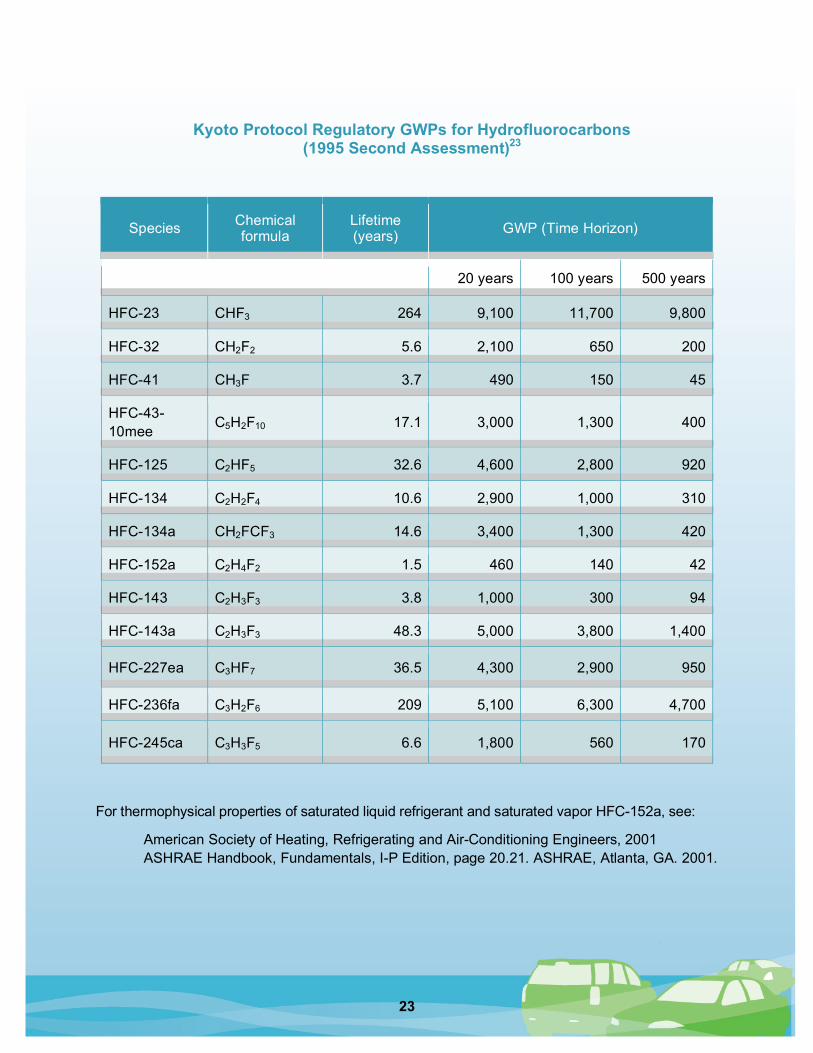
Kyoto Protocol Regulatory GWPs for Hydrofluorocarbons
(1995 Second Assessment)23
Species Chemical formula
Lifetime (years) GWP (Time Horizon)
20 years 100 years 500 years
HFC-23 CHF3 264 9,100 11,700 9,800
HFC-32 CH2F2 5.6 2,100 650 200
HFC-41 CH3F 3.7 490 150 45
HFC-43-10mee
C5H2F10 17.1 3,000 1,300 400
HFC-125 C2HF5 32.6 4,600 2,800 920
HFC-134 C2H2F4 10.6 2,900 1,000 310
HFC-134a CH2FCF3 14.6 3,400 1,300 420
HFC-152a C2H4F2 1.5 460 140 42
HFC-143 C2H3F3 3.8 1,000 300 94
HFC-143a C2H3F3 48.3 5,000 3,800 1,400
HFC-227ea C3HF7 36.5 4,300 2,900 950
HFC-236fa C3H2F6 209 5,100 6,300 4,700
HFC-245ca C3H3F5 6.6 1,800 560 170
For thermophysical properties of saturated liquid refrigerant and saturated vapor HFC-152a, see:
American Society of Heating, Refrigerating and Air-Conditioning Engineers, 2001 ASHRAE Handbook, Fundamentals, I-P Edition, page 20.21. ASHRAE, Atlanta, GA. 2001.

24
8.3. HFC-152a Flammability Properties
Flammability Limits: LFL = 4.2%; upper flammable limit (UFL) = 17.8%24 Tested according to ASTM E681-01
“Standard Test Method for Concentration Limits of Flammability of Chemicals” (15,000V ignition source with electrodes at 6.3 mm)
Minimum Ignition Energy (MIE) ~= 0.35 mJ at 11% concentration in air25 Tested according to ASTM E582-88
“Standard Test Method for Minimum Ignition Energy and Quenching Distance in Gaseous Mixtures” (high voltage capacitive discharge with electrode gap of 2.0–2.3 mm).
Electrical ignition of combustion at 530mJ and above arcing in relays Tested with 20-liter stainless steel vessel Relays without covers or with holes and slots in covers Wire disconnections under load No electrical ignition from components due to current commutation HVAC blower, alternator, and starter stalled for 5 minutes
Ignition of HFC-152a refrigerant/oil mixture sprays in 4 to 59 seconds Tested according to ASTM D 3065-72
“Standard Test Method for Flammability of Aerosol Products, Part Three: Closed Drum Test,” (55 gallon drum on its side) 95% R-152a liquid with 5% PAG 99% R-152a liquid with 1% PAG 99% R-152a vapor with 1% PAG
Ignition of HFC-152a refrigerant/oil mix on hot surface at 500° C No ignition of HFC-152a refrigerant alone (up to 850° C) Sprayed onto 0.5-inch thick, 8.0 inch x 8.0 inch heated vertical steel plate
Steady state gas-phase flame extension at up to 0.07 grams/second With nozzle diameters = 0.043 and 0.072 for HFC-152a
95% to 100% liquid R-152a with corresponding PAG 75% to 100% vapor R-152a with corresponding PAG 75% vapor & 95% liquid R-134a with corresponding PAG
Limited range stable liquid-phase jet flame at 0.3 to 1.5 grams/second With nozzle diameters = 0.043 and 0.072 for HFC-152a
95% to 100% liquid R-152a with corresponding PAG 75% to 100% vapor R-152a with corresponding PAG 75% vapor & 95% liquid R-134a with corresponding PAG
No significant flame impingement on materials No ignition of coolant overflow container at 100° C after 10 seconds jet flame If ignited, plastic overflow container will burn when empty
95% to 99% R-152a vapor with corresponding PAG 95% to 99% R-152a liquid with corresponding PAG
25
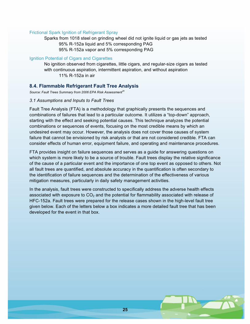
Frictional Spark Ignition of Refrigerant Spray Sparks from 1018 steel on grinding wheel did not ignite liquid or gas jets as tested
95% R-152a liquid and 5% corresponding PAG 95% R-152a vapor and 5% corresponding PAG
Ignition Potential of Cigars and Cigarettes No ignition observed from cigarettes, little cigars, and regular-size cigars as tested with continuous aspiration, intermittent aspiration, and without aspiration 11% R-152a in air
8.4. Flammable Refrigerant Fault Tree Analysis Source: Fault Trees Summary from 2006 EPA Risk Assessment26
3.1 Assumptions and Inputs to Fault Trees
Fault Tree Analysis (FTA) is a methodology that graphically presents the sequences and combinations of failures that lead to a particular outcome. It utilizes a “top-down” approach, starting with the effect and seeking potential causes. This technique analyzes the potential combinations or sequences of events, focusing on the most credible means by which an undesired event may occur. However, the analysis does not cover those causes of system failure that cannot be envisioned by risk analysts or that are not considered credible. FTA can consider effects of human error, equipment failure, and operating and maintenance procedures.
FTA provides insight on failure sequences and serves as a guide for answering questions on which system is more likely to be a source of trouble. Fault trees display the relative significance of the cause of a particular event and the importance of one top event as opposed to others. Not all fault trees are quantified, and absolute accuracy in the quantification is often secondary to the identification of failure sequences and the determination of the effectiveness of various mitigation measures, particularly in daily safety management activities.
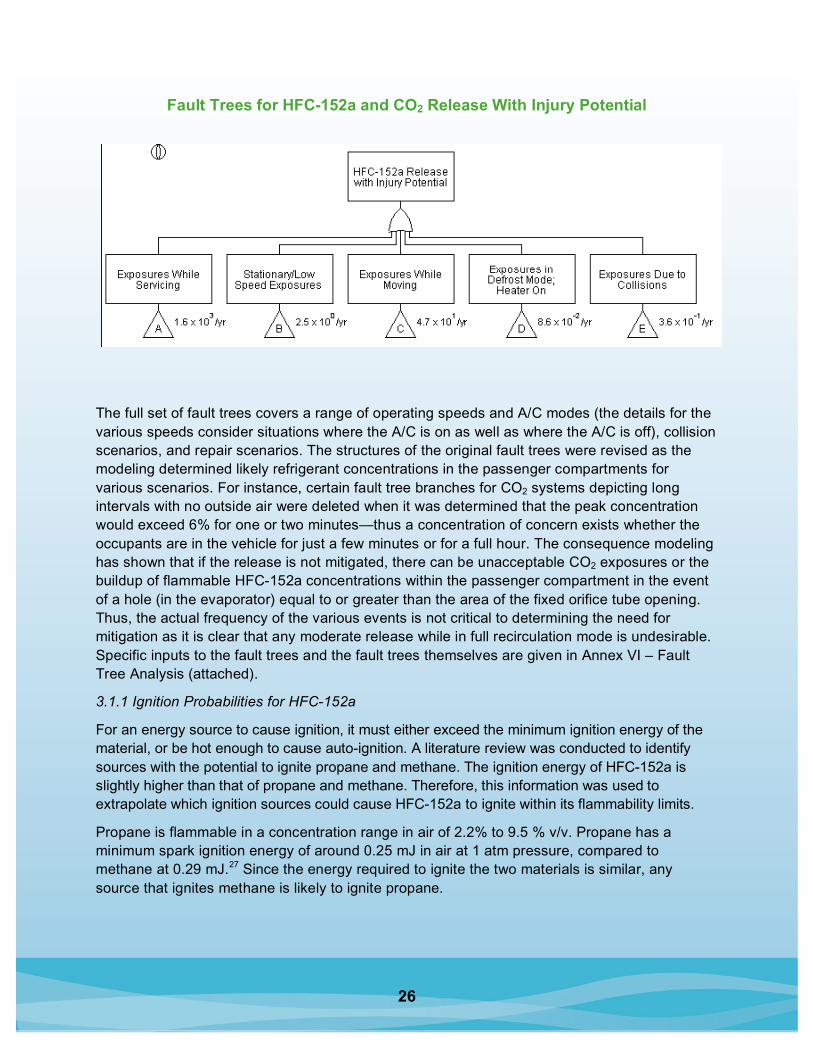
In the analysis, fault trees were constructed to specifically address the adverse health effects associated with exposure to CO2 and the potential for flammability associated with release of HFC-152a. Fault trees were prepared for the release cases shown in the high-level fault tree given below. Each of the letters below a box indicates a more detailed fault tree that has been developed for the event in that box.
26
Fault Trees for HFC-152a and CO2 Release With Injury Potential
The full set of fault trees covers a range of operating speeds and A/C modes (the details for the various speeds consider situations where the A/C is on as well as where the A/C is off), collision scenarios, and repair scenarios. The structures of the original fault trees were revised as the modeling determined likely refrigerant concentrations in the passenger compartments for various scenarios. For instance, certain fault tree branches for CO2 systems depicting long intervals with no outside air were deleted when it was determined that the peak concentration would exceed 6% for one or two minutes—thus a concentration of concern exists whether the occupants are in the vehicle for just a few minutes or for a full hour. The consequence modeling has shown that if the release is not mitigated, there can be unacceptable CO2 exposures or the buildup of flammable HFC-152a concentrations within the passenger compartment in the event of a hole (in the evaporator) equal to or greater than the area of the fixed orifice tube opening. Thus, the actual frequency of the various events is not critical to determining the need for mitigation as it is clear that any moderate release while in full recirculation mode is undesirable. Specific inputs to the fault trees and the fault trees themselves are given in Annex VI – Fault Tree Analysis (attached).
3.1.1 Ignition Probabilities for HFC-152a
For an energy source to cause ignition, it must either exceed the minimum ignition energy of the material, or be hot enough to cause auto-ignition. A literature review was conducted to identify sources with the potential to ignite propane and methane. The ignition energy of HFC-152a is slightly higher than that of propane and methane. Therefore, this information was used to extrapolate which ignition sources could cause HFC-152a to ignite within its flammability limits.
Propane is flammable in a concentration range in air of 2.2% to 9.5 % v/v. Propane has a minimum spark ignition energy of around 0.25 mJ in air at 1 atm pressure, compared to methane at 0.29 mJ.27 Since the energy required to ignite the two materials is similar, any source that ignites methane is likely to ignite propane.

27
Ignition sources can be categorized into four main types, including electrical, open flames, hot surfaces, and friction. Table 5 summarizes the main sources known to ignite propane, identified during the literature review.
Potential Ignition Sources
Type of Ignition Source Sources With Potential to Ignite
Electrical Arc, electrostatic spark, high-load electrical switching, damaged electrical components
Open Flame Match/lighter, gas pilot, fuel heater, open fire
Hot Surface Heater element
Miscellaneous Frictional spark
More detailed information on each type of ignition source is shown below.
A study by the Arthur D. Little Company for the Gas Research Institute investigated ignition by electrical circuits in a stoichiometric mixture of methane/air.28 While ignition did not occur for a typical electric wall clock, vehicle radio, CB, or a 25-watt incandescent lamp, ignition did occur for 100-watt incandescent lamps, traffic lights, toasters, space heaters, clothes dryers, and arc welding.
The same study also discussed ignition by automotive electrical components in a 7% methane in air environment. This testing concluded that ignition is not caused by any normal operation of the electrical system (i.e., by the alternator, starter relay, distributor, and spark plug in housing). Ignition only occurred when either a loosened starter wire or a broken ignition wire was used.
Ignition of propane mixtures by electrostatic sparks from human bodies was reported in a number of sources. Common movements such as walking across a carpet, getting out of a vehicle, or removing a garment can generate and induce enough charge on the body for any subsequent discharge to have sufficient energy to ignite flammable gases and vapors. The charging characteristics of clothing, shoes, rugs, and carpet play a critical role in determining the likelihood of producing a spark that could ignite flammable vapors and gases. However, another source tested ignition of a stoichiometric mixture of natural gas and air by a spark generated from a human body.29 The lowest voltage at which ignition was obtained was 6.0 kV with a corresponding energy of 1.7 mJ. This is 4.3 times the minimum ignition energy of natural gas which is 0.39 mJ. This suggests that when sparks are the potential ignition source, more energy is required than for some other ignition sources.

28
Ignition by cigarettes is not considered a credible event based on ignition testing with 7% methane in air. Three brands were tested to cover a wide range of chemical tobacco treatment and curing which could affect the burning rate and local temperatures. Both a puffing and a nonpuffing cigarette did not cause ignition. However, the match or lighter used to light the cigarette could cause ignition.30 One reference31 discusses ignition of propane by heated surfaces and also by frictional impact between tungsten carbide-tipped steel and sandstone. A coal-cutting pick striking sandstone also ignited propane-air mixture when the temperature on impact exceeded 1400o C. These hot surfaces are not found inside the passenger compartment and therefore were not included as ignition sources in the fault trees.
Underwriters Laboratories found that there was a very low probability of ignition from a leaked hydrocarbon refrigerant from household appliances. There are few readily available ignition sources that would occur at the same time as a leak in the space where the fuel/air mixture is between the LFL and the UFL.
Considering all of the above, the fault trees only consider open flames (matches, butane lighters) as potential ignition sources in the vehicle passenger compartment. Static electric sparks were not considered credible ignition sources both because research shows that the minimum spark energy generated from a human body was four times higher than the minimum ignition energy of methane. Further, a seated passenger is highly unlikely to generate a spark since we would not expect a buildup of charge while the occupant is sitting in the vehicle.
It should also be noted that these past results also support the decision to limit the risk analysis to leaks within the passenger compartment. In the future it is possible that other credible sources of ignition, such as electric heating elements, could be added to the passenger compartment. The fault tree does not consider any new ignition sources that are not currently in standard vehicle designs.
3.2 FTA Results
The detailed fault trees are presented in Annex VI – Fault Tree Analysis, along with descriptions of their quantification. The overall results for the different scenarios are shown below. The fault trees for each refrigerant (HFC-152a and CO2) both assume that the full fleet of US passenger vehicles is using that refrigerant.
Since HFC-152a scenarios require ignition to have the hazardous exposure occur, the frequencies are lower than for the corresponding CO2 scenarios. However, the occurrence of a CO2 exposure will not always result in adverse consequences. Such consequences will depend on the health of the individual, the exact air flow patterns in the specific vehicle, whether a window is opened or outside air is introduced through the ventilation system, etc. The CFD modeling for CO2 predicted only very short duration exposures to high concentrations.
Furthermore, all predicted frequencies are considered to be conservative (upper range estimates of worst-case scenarios).

29
Projected Unmitigated Leak Scenario Occurrence Frequencies for HFC-152a Systems32
Scenario
Frequency of Exposure to Large Leak With Ignition Source Present
Technician Exposures While Servicing 1,600/yr
Passenger Compartment Exposures 50/yr
Stationary/Low-speed Exposures 2.5/yr
Exposures While Moving 50/yr
Exposures While in Defrost Mode, Heater on 0.09/yr
Exposures Due to Collision 0.4/yr
The fault tree analysis identified a number of credible pathways resulting in undesirable risk from refrigerant released due to equipment failure or collision. Routine or collision failures of the evaporator are not likely, but the risk of this occurring becomes significant when applied across the full fleet of passenger vehicles.
Therefore, mitigation strategies to limit or eliminate the amount of charge that can leak into the passenger compartment are necessary. In addition, the total risk resulting from a leak into the passenger compartment is dominated by the risk that a driver is startled by a sound from the refrigerant release. It was estimated that 50% of drivers were startled and that 10% of these drivers lost control and had an accident. This scenario accounts for more than 90% of the “exposures” in the HFC-152a systems and for about 40% in the CO2 systems. Because there is no information on whether these systems are likely to rupture with a large and potentially startling noise, conservative estimates were selected. It is likely that the actual occurrence of these events would be much lower than calculated. The chance of an undesired exposure while servicing vehicles containing these refrigerants depends not only on the number of vehicles a given service technician or shop handles, but also on their experience and training.
However, with proper mitigation (see the 2006 EPA Risk Assessment’s Annex V – Critical Findings of MACS Meeting on August 28, 2003 for suggestions), the frequency of these exposures can be reduced dramatically. The estimated exposures are distributed across several hundred thousand technicians. Interestingly, the chance of exposures for technicians does not vary considerably by refrigerant.
30
8.5. Annotated CalTech Glossary on Explosion Dynamics
California Institute of Technology, Explosion Dynamics Laboratory (Sponsored by Sandia National Laboratory and the DoE (SC))
Some of the language used to describe explosions is very precise and scientific; other terms, including the very nature of an explosion itself, are quite ambiguous. The following list of terms is not intended to be exhaustive but simply to provide an explanation for some of the most commonly used concepts.
Autoignition temperature (AIT) The temperature that a fixed volume of fuel-oxidizer mixture must be heated to before an explosion will take place without an external ignition source, i.e., spark or flame.
Burning speed The speed with which a smooth (laminar) flame advances into a stationary mixture of reactants. Burning speeds in hydrocarbon fuels mixed with air are typically less than 0.5 meters/second (m/s). The burning speed is a function of the concentration of the fuel, temperature, and pressure of the mixture.
Explosion There is no fixed definition of an explosion. Events that are described as explosions include a rupturing water boiler, a flash of light created by an electrical short circuit, detonation of a high explosive, deflagration of a tank containing an explosive fuel-air mixture, or the shock wave, fireball, and debris cloud produced by a thermonuclear detonation.
Explosion limits Explosion limits usually refer to the range of pressure and temperature for which an explosive reaction at a fixed composition mixture is possible. The reaction is usually initiated by autocatalytic (sometimes called self-heating) reaction at those conditions, without any external ignition source.
Expansion ratio Ratio of burned gas volume to initial volume for a low-speed (constant pressure) flame. Expansion is responsible for flame-induced flow.
Fire This is a flame that is produced over a stationary fuel source such as a liquid hydrocarbon pool or solid such as wood.
Flame This is a thin zone of combustion in which diffusion plays a dominant role. Flames in HC fuels and air are less than 0.1 mm thick for stoichiometric mixtures.
Flame acceleration Rapid increase in flame speed due to generation of large and small eddies—turbulence—as flow ahead of flame passes over objects or through orifices.
Flame speed The speed with which a flame, possibly turbulent, appears to move relative to a stationary observer. The flame speed can be much larger than the burning velocity due to expansion of the combustion products, instability, and turbulent deformation of the flame.
Flame Stretch Measure of the rate at which the area of a propagating flame surface is changing due to curvature of flame surface and strain (gradients in velocity) in flow ahead of the flame. Units of reciprocal time.

31
Flame Thickness Characteristic width of flame. One simple estimate is based on the ratio of the thermal diffusivity to the fame speed.
Flammability limits A fuel-air mixture is flammable when combustion can be started by an ignition source. The main factor is the proportions or composition of the fuel-air mixture. A mixture that has less than a critical amount of fuel, known as the Lean or Lower Flammability Limit (LFL), or greater than a critical amount of fuel, known as the rich or Upper Flammability Limit (UFL), will not be flammable.
Flash point This is the minimum temperature at which the vapor above a liquid fuel will first support a combustion transient or "flash". The legal description of flammable is used for all liquids with a flash point less than 100 deg C, and the term combustible is used for liquids with a flash point in excess of 100 deg C.
Fuel-air mass ratio This is the ratio of the mass of fuel to the mass of air in the reactants. The fuel-air ratio is a method of measuring the composition of a potentially flammable mixture.
Heat of combustion The ideal amount of energy that can be released by burning a unit amount of fuel. This is between 45 and 50 MJ/kg for kerosenes.
Minimum Ignition Energy This is the lowest possible energy that will result in the ignition of a flammable mixture by an electrical discharge. The minimum ignition energy depends on the composition of the mixture and can be as low as 200 microJoules for many common HC fuels.
Overpressure The pressure in excess of the ambient value that is created by the explosion process. The peak overpressure associated with deflagrations inside closed vessels can be as high as 10 times the initial pressure.
Partial pressure The pressure created by one component of a gas mixture. The partial pressure of fuel vapor in a well-mixed ullage over a liquid fuel layer is equal to the vapor pressure of the liquid under those conditions.
Pool Fire The flame over a puddle or pool of liquid fuel. The heat released by the combustion of the vapor fuel supplies the energy to vaporize the liquid.
Quenching The cessation of combustion due to either heat transfer and mass transfer to the surface or aerodynamic effects such as strain fields and rapid mixing.
Stoichiometric ratio The proportions of fuel and oxidizer that will result in optimal combustion are known as a stoichiometric ratio. The optimal ratio is determined by finding the amount of air that will result in the products of the combustion reaction containing only water and CO2 with no left over oxygen.
HFC-152a Technical Literature Database (CD) A CD of HFC-152a Technical Literature is available from EPA upon request. To request a CD, send your name and address to Kristen Taddonio by e-mail at [email protected], or call 202-343-9234.
32
1 GWPs are determined as the ratio of the time-integrated radiative forcing arising from a pulse
emission of 1 kilogram (kg) of a substance relative to that of 1 kg of CO, over a fixed time horizon
(typically selected by policymakers as 100 years).
2 See: FCCC/SBSTA/2004/8, http://unfcc.int/resources/docs/2004/sbsta/08.pdf.
3 Andersen, Hovland, and Rugh (2004). Significant Fuel Savings and Emission Reductions by
Improving Vehicle Air Conditioning. NREL, Boulder, CO.
4 Chaney, L.; Thundiyil, K.; Chidambaram, S.; Abbi, Y.P.; Andersen, S. “Fuel Savings and Emission
Reductions From Next-Generation Mobile Air Conditioning Technology in India.” Eighth Vehicle
Thermal Management Systems Conference Proceedings; May 20–24, 2007. Paper No.
C640/085/2007.
5 EPA. Retrieved August 30, 2007, from http://www.epa.gov/cppd/mac/; conversion of 7 billion gallons
of gasoline into CO2-eq done at http://www.usctcgateway.net/tool/.
6 EPA (April 15, 2007). Inventory of U.S. Greenhouse Gas Emissions and Sinks: 1990–2005.
Washington, DC. Pages 2–28 and 2–29.
7 Capacity controls for direct expansion systems can capture some of these fuel saving benefits.
8 The orifice is a fixed expansion device. It is typically simpler and cheaper than a thermostatic
expansion valve or other devices able to regulate the expansion pressure drop depending on the loop
working conditions. Normally the orifice is selected to guarantee the best performance in a specific
working point (e.g. severe summer conditions), with the consequence that the system is likely less
efficient at other operating conditions (e.g. mild temperature conditions).
9 Ray, R., Ahrens, M., “Vehicle Fire Data: Different Sources, Different Goals, Different Conclusions?”
SAE 2007-01-0877.
10 Ibid and Davies, B. T., Griffin, L. I., “A Clinical Evaluation of the Death Investigations for 206
Decedents Who Died in Passenger Vehicles That Experienced Post-Crash Fires,” NHTSA docket
number 98-3588-170, 2002.
11 Shields, L., Scheibe, R., Thomas, T., “Vehicle Design for Fire Safety and Evaluation of Design Trade-
offs,” SAE 2007-01-0879.
12 Ray, R., Ahrens, M., “Vehicle Fire Data: Different Sources, Different Goals, Different Conclusions?”
SAE 2007-01-0877.
13 Shields, L., Scheibe, R., Thomas, T., “Vehicle Design for Fire Safety and Evaluation of Design Trade-
offs,” SAE 2007-01-0879.
14 Heckenberger, T., “Flammability Properties of R152a versus Hydrocarbons,” SAE 2005-01-2042.
15 Korb, T., Colwell, J., “R152a Refrigerant Concentration and Ignition Tests in Full-Scale Vehicle
Passenger Cabins,” Prepared for SAE, February 2007.
16 Scheffler, G., DeVaal, J., Kissel, G., Schneider, J., Veenstra, M., Chang, T., Warner, N., Chernicoff,
W., “Developing Safety Standards for FCVs and Hydrogen Vehicles,” SAE 2007-01-0436.

33
17 Blackwell, N., Bendixen, L. and Birgfeld, E. (September 2006) Risk Analysis for Alternative
Refrigerant in Motor Vehicle Air Conditioning. EPA, Washington, DC, p. 35.
18 Ibid.
19 Blackwell, N., Bendixen, L., and Birgfeld, E. (September 2006) Risk Analysis for Alternative
Refrigerant in Motor Vehicle Air Conditioning. EPA, Washington, DC, p. 63.
20 This standard applies to vehicles with gross vehicle weight ratings (GVWR) of 4,536 kg (10,000
pounds) or less and includes frontal, rear, and side impact tests. In the frontal impact test, the test
vehicle is driven forward into a fixed barrier at 48 km/h (30 mph). In the rear impact test, a 1,814 kg
(4,000 pound) barrier moving at 48 km/h (30 mph) is guided into the full width of the rear of a
stationary test vehicle. In the side impact test, a 1,814 kg (4,000 pound) barrier moving at 32 km/h (20
mph) is guided into the side of a stationary test vehicle.
21 Some authorities list the actual heat of combustion of R-152a as 6.3 MJ/kg, versus the theoretical
17.4. At 6.3 MJ/kg., the fire risk of a full discharge of 350 grams of HFC-152a would be one-third of
the allowed gasoline spill prior to the vehicle coming to rest, and less than 10% of the allowed
gasoline spill in the first five minutes after collision.
22 Calm, J.M., and Hourahan, G.C., “Refrigerant Data Update,” Heating/Piping/Air Conditioning
Engineering, 79 (1), 50–64, January 2007, with the exception that the GWP is the IPCC 2nd
Assessment 100-year value.
23 Climate Change 1995, The Science of Climate Change: Summary for Policymakers, and Technical
Summary of the Inter-Governmental Panel on Climate Change Working Group I Report, p. 22,
Cambridge University Press.
24 Determination of Refrigerant Lower Flammability Limits in Compliance with Proposed Addendum p to
Standard 34, David P. Wilson and Robert G. Richard, ASHRAE Transactions 2002, Volume 108, Part
2, p.746–747.
25 International Symposium of Hazards, Prevention and Mitigation of Industrial Explosions, Christian
Michelsen Research AS, Bergen, Norway, 26–28 June 1996.
26 The complete fault tree summary is available in Blackwell, N., Bendixen, L., and Birgfeld, E.
(September 2006) Risk Analysis for Alternative Refrigerant in Motor Vehicle Air Conditioning. EPA,
Washington DC.
27 The Investigation and Control of Gas Explosions in Buildings and Heating Plant, R.J. Harris, ISBN 0-
419-13220-1, 1983.
28 Ignition sources of LNG [liquefied natural gas] vapor clouds, Arthur D. Little for Gas Research
Institute (GRI-80/0108), January 1982.
29 The ignition of natural gas by spark discharges from the body, Wilson, P., The Institute of Physics
Conference Series, No. 66, pp. 21–27, 1983.
30 Ignition sources of LNG vapor clouds, Arthur D. Little for Gas Research Institute (GRI-80/0108),
January 1982.

34
31 Further Studies of the Ignition of Gases by Transiently Heated Surfaces, D.P. Cutter, Combustion and
Flame 33, pp. 85–91, 1978.
32 These values are consistent with unpublished fault tree estimates values being used by US and
European vehicle manufacturers in evaluating new low-GWP substance blends proposed as GARs.