Heat Exchanger Replacement For a Shorter Heat Exchanger … · 2019-12-03 · Replacement Procedure...
8
SAFETY WARNING Only qualified personnel should install and service the equipment. The installation, starting up, and servicing of heating, ventilating, and air-conditioning equipment can be hazardous and requires specific knowledge and training. Improperly installed, adjusted or altered equipment by an unqualified person could result in death or serious injury. When working on the equipment, observe all precautions in the literature and on the tags, stickers, and labels that are attached to the equipment. Heat Exchanger Replacement For a Shorter Heat Exchanger Replacement Installation Instructions PART-SVN114A-EN December 2015 Models Y*C072A**(L/X) YSC072E**(M/Y) YSC(090/092)A**(L/X) YSC072E**(L/X) Y*C072A**(H/Z) YSC(090/092)A**(M/Y) Y*C072A**(M/Y) YSC072E**(H/Z) YSC(090/092)A**(H/Z)
Transcript of Heat Exchanger Replacement For a Shorter Heat Exchanger … · 2019-12-03 · Replacement Procedure...

SAFETY WARNINGOnly qualified personnel should install and service the equipment. The installation, starting up, and servicing of heating, ventilating, and air-conditioning equipment can be hazardous and requires specific knowledge and training. Improperly installed, adjusted or altered equipment by an unqualified person could result in death or serious injury. When working on the equipment, observe all precautions in the literature and on the tags, stickers, and labels that are attached to the equipment.
Heat Exchanger Replacement
For a Shorter Heat Exchanger Replacement
Installation
Instructions
PART-SVN114A-ENDecember 2015
Models Y*C072A**(L/X) YSC072E**(M/Y) YSC(090/092)A**(L/X)YSC072E**(L/X) Y*C072A**(H/Z) YSC(090/092)A**(M/Y)Y*C072A**(M/Y) YSC072E**(H/Z) YSC(090/092)A**(H/Z)

Introduction
Read this manual thoroughly before operating or servicing this unit.
Warnings, Cautions, and Notices
Safety advisories appear throughout this manual as required. Your personal safety and the proper operation of this machine depend upon the strict observance of these precautions.
Important Environmental Concerns
Scientific research has shown that certain man-made chemicals can affect the earth’s naturally occurring stratospheric ozone layer when released to the atmosphere. In particular, several of the identified chemicals that may affect the ozone layer are refrigerants that contain Chlorine, Fluorine and Carbon (CFCs) and those containing Hydrogen, Chlorine, Fluorine and Carbon (HCFCs). Not all refrigerants containing these compounds have the same potential impact to the environment. Trane advocates the responsible handling of all refrigerants-including industry replacements for CFCs such as HCFCs and HFCs.
Important Responsible Refrigerant Practices
Trane believes that responsible refrigerant practices are important to the environment, our customers, and the air conditioning industry. All technicians who handle refrigerants must be certified. The Federal Clean Air Act (Section 608) sets forth the requirements for handling, reclaiming, recovering and recycling of certain refrigerants and the equipment that is used in these service procedures. In addition, some states or municipalities may have additional requirements that must also be adhered to for responsible management of refrigerants. Know the applicable laws and follow them.
The three types of advisories are defined as follows:
WARNINGIndicates a potentially hazardous situation which, if not avoided, could result in death or serious injury.
CAUTIONsIndicates a potentially hazardous situation which, if not avoided, could result in minor or moderate injury. It could also be used to alert against unsafe practices.
NOTICE: Indicates a situation that could result in equipment or property-damage only accidents.
WARNING
Proper Field Wiring and Grounding Required!
Failure to follow code could result in death or serious injury. All field wiring MUST be performed by qualified personnel. Improperly installed and grounded field wiring poses FIRE and ELECTROCUTION hazards. To avoid these hazards, you MUST follow requirements for field wiring installation and grounding as described in NEC and your local/state electrical codes.
WARNING
Personal Protective Equipment (PPE) Required!
Installing/servicing this unit could result in exposure to electrical, mechanical and chemical hazards.
• Before installing/servicing this unit, technicians
MUST put on all PPE required for the work being
undertaken (Examples; cut resistant gloves/sleeves,
butyl gloves, safety glasses, hard hat/bump cap, fall
protection, electrical PPE and arc flash clothing).
ALWAYS refer to appropriate Material Safety Data
Sheets (MSDS)/Safety Data Sheets (SDS) and OSHA
guidelines for proper PPE.
• When working with or around hazardous chemicals,
ALWAYS refer to the appropriate MSDS/SDS and
OSHA/GHS (Global Harmonized System of
Classification and Labelling of Chemicals) guidelines
for information on allowable personal exposure
levels, proper respiratory protection and handling
instructions.
• If there is a risk of energized electrical contact, arc, or
flash, technicians MUST put on all PPE in accordance
with OSHA, NFPA 70E, or other country-specific
requirements for arc flash protection, PRIOR to
servicing the unit. NEVER PERFORM ANY
SWITCHING, DISCONNECTING, OR VOLTAGE
TESTING WITHOUT PROPER ELECTRICAL PPE AND
ARC FLASH CLOTHING. ENSURE ELECTRICAL
METERS AND EQUIPMENT ARE PROPERLY RATED
FOR INTENDED VOLTAGE.
Failure to follow instructions could result in death or serious injury.
© 2015 Trane All rights reserved PART-SVN114A-EN

Introduction
Copyright
This document and the information in it are the property of Trane, and may not be used or reproduced in whole or in part without written permission. Trane reserves the right to revise this publication at any time, and to make changes to its content without obligation to notify any person of such revision or change.
Trademarks
All trademarks referenced in this document are the trademarks of their respective owners.
Revision History
PART-SVN114A-EN (15 Dec 2015)
• First version of this literature
WARNING
Hazardous Voltage and Gas!
Failure to turn off gas or disconnect power before servicing could result in an explosion or electrocution which could result in death or serious injury. Turn off the gas supply and disconnect all electric power, including remote disconnects, before servicing the unit. Follow proper lockout/tagout procedures to ensure the power can not be inadvertently energized.
PART-SVN114A-EN 3
General Information
Model Number Description
All products are identified by a multiple-character model number that precisely identifies a particular type of unit. Its use will enable the owner/operator, installing contractors, and service engineers to define the operation, specific components, and other options for any specific unit.
When ordering replacement parts or requesting service, be sure to refer to the specific model number and serial number printed on the unit nameplate.
Tools Required
• 5/16 in. Driver
• 5/16 in. Long Driver (12–15 in.)
• 5/16 in. Ratchet
• 9/16 in. Wrench
• 1/2 in. Socket
• Ratchet Extension
• Tube of RTV—Max temperature rating of 500°F (field supplied)
• Screw (used to secure air baffle)—#10-16; 0.5 in. long (field supplied)
• Drill
• 5/16 in. Drill bit
• 1/8 in. Drill bit
4 PART-SVN114A-EN

Replacement Procedure
1. Shut off all electrical power to unit.
2. Shut off and disconnect gas service to unit.
3. Disconnect any piping from unit condensate drain.
4. Remove all access panels, front center posts, and rear duct cover. If the unit is configured for horizontal supply, remove the connecting ductwork.
5. Remove condensate drain pan.
6. Clip any wire ties that secure wires to one another in the gas heat compartment. Be careful not to damage any wiring when doing this.
7. Disconnect wires from the various components in the gas heat compartment (TCO1, Pressure Switch, Gas Valve, etc.).
8. Route wires out of gas heat compartment through plastic grommet on the right side of the compartment. Be sure NOT to discard the foam insulation that is used to plug this hole.
9. Remove smaller plastic grommet on the right side of the gas heat compartment. This is the opening where the high voltage spark ignition wire is routed through. Remove this wire as well.
10. Disconnect the orange pressure switch hose from the pressure switch.
11. Remove the gas valve and burner assembly by removing the four screws shown in Figure 1.
12. Remove TCO1 limit and turbulators shown in Figure 2.
13. Remove the inducer motor shown in Figure 2. If the gasket behind the part is damaged, replace with the new gasket provided in the kit.
14. Remove the air orifice. Please note that when installing the new heat exchanger, this air orifice plate may need to be changed out, depending on the unit (refer to Table 1, p. 7).
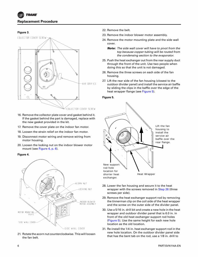
15. Remove the screws shown in Figure 3 to take out the collector cover. Note that these screws are longer than the other screws in the unit. Set these aside and do not mix them in with other screws.
WARNING
Hazardous Voltage and Gas!
Failure to turn off gas or disconnect power before servicing could result in an explosion or electrocution which could result in death or serious injury. Turn off the gas supply and disconnect all electric power, including remote disconnects, before servicing the unit. Follow proper lockout/tagout procedures to ensure the power can not be inadvertently energized.
WARNING
Hazardous Gases and Flammable Vapors!
Failure to observe following instructions could result in death or serious injury. Exposure to hazardous gases from fuel substances have been shown to cause cancer, birth defects or other reproductive harm. Improper installation, adjustment, alteration, service or use of this product could cause flammable mixtures or lead to excessive carbon monoxide. To avoid hazardous gases and flammable vapors follow proper installation and set up of this product and all warnings as provided in this manual.
Figure 1.
Figure 2.
PART-SVN114A-EN 5
Replacement Procedure
16. Remove the collector plate cover and gasket behind it. If the gasket behind the part is damaged, replace with the new gasket provided in the kit.
17. Remove the cover plate on the indoor fan motor.
18. Loosen the strain relief on the indoor fan motor.
19. Disconnect motor wiring and remove wiring from motor housing.
20. Loosen the locking nut on the indoor blower motor mount (see Figure 4, p. 6).
21. Rotate the acorn nut counterclockwise. This will loosen the fan belt.
22. Remove the belt.
23. Remove the indoor blower motor assembly.
24. Remove the motor mounting plate and the side wall cover.
Note: The side wall cover will have to pivot from the top because copper tubing will be routed from the condensing section to the evaporator.
25. Push the heat exchanger out from the rear supply duct through the front of the unit. Use two people when doing this so that the unit is not damaged.
26. Remove the three screws on each side of the fan housing.
27. Lift the rear side of the fan housing (closest to the outdoor divider panel) and install the service air baffle by sliding the clips in the baffle over the edge of the heat wrapper flange (see Figure 5).
28. Lower the fan housing and secure it to the heat wrapper with the screws removed in Step 26 (three screws per side).
29. Remove the heat exchanger support rod by removing the tinnerman clip on the coil side of the heat wrapper and the screw on the outer side of the divider panel.
30. Use a 5/16 in. drill bit and create a new hole in the heat wrapper and outdoor divider panel that is 6.0 in. in front of the old heat exchanger support rod holes (Figure 5). Use the same height for each new hole location as the old location.
31. Re-install the 1/4 in. heat exchanger support rod in the new hole location. On the outdoor divider panel side that has the bent tab on the rod, use a 1/8 in. drill to
Figure 3.
Figure 4.
Figure 5.
Lift the fan housing to install the service air baffle over the rear flange.
New support rod hole location for shorter heat exchanger.
6 in.
Heat Wrapper
6 PART-SVN114A-EN

Replacement Procedure
create a hole to secure the rod to the divider with the previously removed #10-16 x 1/2 in. sheet metal screw.
32. Install the new heat exchanger. Feed heat exchanger through the front of the unit. Use two people in this process to ensure that the unit and heat exchanger are not damaged. The second person should be helping to align the heat exchanger from the rear duct opening of
the unit. Make sure that the heat exchanger catches the support rod between the bottom primary tube and the tube directly above it.
Note: The supplied heat exchanger may be different than what was removed. Reference Table 1 to determine the parts required to install the replacement heat exchanger.
33. Seal the heat exchanger with a bead of high temperature silicon (field provided; see Figure 6). If the unit is a YSC(090/092)A**(H/Z) unit, install the turbulators provided in the kit.
34. Reassemble the unit. Retrace Step 24 through Step 1.
35. Verify the alignment of the indoor blower fan belt.
Table 1. Parts to install in the replacement heat exchanger
Model NumberSize of Old Heat Exchanger
Size of New Heat Exchanger
Turbulators Installed in Replacement?
New TCO1 Limit Installed in Replacement?
New Air Orifice Installed in Replacement?
Y*C072A**(L/X)YSC072E**(L/X)
2 x 2 longer tubes 2 x 3 shorter tubes No Yes; X13100424070 No
Y*C072A**(M/Y)YSC072E**(M/Y)
3 x 3 longer tubes 3 x 4 shorter tubes No Yes; X13100424010 Yes; 436646150310
Y*C072A**(H/Z)YSC072E**(H/Z)
3 x 4 longer tubes 3 x 5 shorter tubes No Yes; X13100424110 for downflow; X13100424010 for horizontal Yes; 436646150210
YSC(090/092)A**(L/X) 3 x 3 longer tubes 3 x 4 shorter tubes No Yes; X13100424010 Yes; 436646150310
YSC(090/092)A**(M/Y) 3 x 4 longer tubes 3 x 5 shorter tubes No Yes; X13100424070 Yes; 436646150210
YSC(090/092)A**(H/Z) 4 x 5 longer tubes 4 x 5 longer tubes Yes Yes; X13100424020 for downflow; X13100424050 for horizontal No
Figure 6.
PART-SVN114A-EN 7
Trane optimizes the performance of homes and buildings around the world. A business of Ingersoll Rand, the leader increating and sustaining safe, comfortable and energy efficient environments, Trane offers a broad portfolio of advancedcontrols and HVAC systems, comprehensive building services, and parts. For more information, visit www.Trane.com.
Trane has a policy of continuous product and product data improvement and reserves the right to change design and specifications without notice.
We are committed to using environmentally
conscious print practices that reduce waste.
© 2015 Trane All rights reserved
PART-SVN114A-EN 15 Dec 2015
New