NR98, NC199 and N-0751M Series Heat Exchanger...
16
NR98, NC199 and N-0751M Series Heat Exchanger Replacement Models Include: N-0751M, N-0751M-OD, N-0751M-DV, N-0751M-DVC NR98-SV, NR98-OD, NR98-DVC NC199-OD, NC199-DVC This instructional manual is only intended for use by a qualified service professional or authorized Noritz Service Representative. Any unauthorized use of this manual may result in voiding the warranty. Please contact Noritz Technical Support (866-766-7489) for additional support. Noritz America Corporation 11160 Grace Avenue, Fountain Valley, CA 92708 Phone 866-766-7489 Fax 714-241-1196 Page 1
Transcript of NR98, NC199 and N-0751M Series Heat Exchanger...

NR98, NC199 and N-0751M Series Heat Exchanger Replacement
Models Include: N-0751M, N-0751M-OD, N-0751M-DV, N-0751M-DVC
NR98-SV, NR98-OD, NR98-DVC
NC199-OD, NC199-DVC
This instructional manual is only intended for use by a qualified service professional or authorized Noritz Service Representative. Any unauthorized use of this manual may result in voiding the warranty.
Please contact Noritz Technical Support (866-766-7489) for additional support.
Noritz America Corporation
11160 Grace Avenue, Fountain Valley, CA 92708
Phone 866-766-7489 Fax 714-241-1196
Page 1

NR98 Series, NC199 Series & N-0751M Series Heat Exchanger Replacement Procedure
Procedure Diagram 1. Remove front cover
(1) Remove 4 screws (2) Disconnect electrical power to unit (3) Turn off gas and water (4) Remove filter and drain unit
completely
2. Remove the Remote Control (ONLY DVC UNIT) (1) Remove screw from the bottom of the
metal plate that the controller is mounted to
(2) Let the remote control hang outside the unit or disconnect the wire and set aside
3. Remove GFCI and circuit board
(1) Remove two screws that hold the GFCI
Plate, one screw will have a ground wire attached), Let GFCI hang outside of the unit
(2) Remove the ground wire that is to the left of the circuit board
(3) Remove the circuit board; there are two screws, one on top and bottom of the circuit board
(4) Pull out circuit board and let hang outside of the unit
Page 2

Procedure Diagram 4. Remove gas valve assembly
(1) Locate “C” Clamp on the bottom right
hand corner of the unit that attaches the gas connection to the manifold plate and remove.
(2) Locate inlet gas pipe to manifold and push up. Then locate the large wiring connection, that attaches the wires from the manifold plate to the wiring harness, and disconnect the plug.
(3) Next locate the 4 big silver screws holding the manifold plate to the burner, there will be two on the right and left side of the manifold plate. Remove those 4 screws and the manifold plate and pipe can be removed and set aside.
NOTE: DVC Units will also have a rubber hose attached to the manifold plate. Disconnect that rubber hose.
Page 3
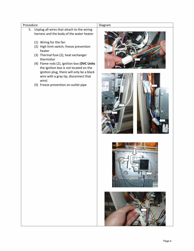
Procedure Diagram 5. Unplug all wires that attach to the wiring
harness and the body of the water heater (1) Wiring for the fan (2) High limit switch, freeze prevention
heater (3) Thermal fuse (2), heat exchanger
thermistor (4) Flame rods (2), ignition box (DVC Units
the ignition box is not located on the ignition plug, there will only be a black wire with a gray tip, disconnect that wire)
(5) Freeze prevention on outlet pipe
Page 4
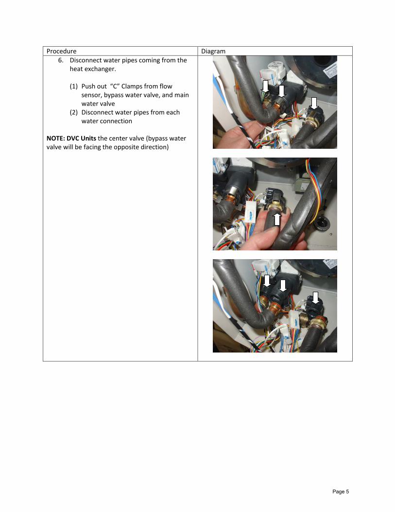
Procedure Diagram 6. Disconnect water pipes coming from the
heat exchanger. (1) Push out “C” Clamps from flow
sensor, bypass water valve, and main water valve
(2) Disconnect water pipes from each water connection
NOTE: DVC Units the center valve (bypass water valve will be facing the opposite direction)
Page 5

Procedure Diagram 7. Remove heat exchanger from case
(1) Remove the 6, 4 or 2 case cover
screws depending on unit (OD Units this step will be skipped)
(2) Loosen wire anchors from each side of case
SV Unit
DV Unit
DVC Unit
Page 6

Procedure Diagram
(3) Remove the 2 set screws on the bottom of the burner
(4) Remove the upper left and right set screws near the top of the case (support bottom of assembly)
(5) The exhaust box, heat exchanger, burner and fan will come out of the case in one section
SV Unit
DV Unit
DVC Unit
OD Unit
Page 7
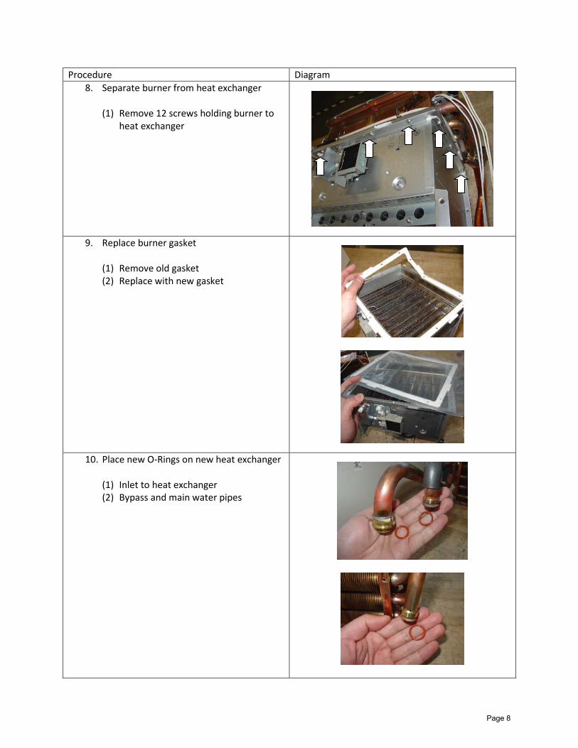
Procedure Diagram 8. Separate burner from heat exchanger
(1) Remove 12 screws holding burner to
heat exchanger
9. Replace burner gasket (1) Remove old gasket (2) Replace with new gasket
10. Place new O-Rings on new heat exchanger (1) Inlet to heat exchanger (2) Bypass and main water pipes
Page 8

Procedure Diagram 11. Remove heat exchanger components
from old heat exchanger and put on new heat exchanger (1) Outlet freeze prevention heater (2) Inlet heat exchanger pipe (3) High limit switch (4) Heat exchanger thermistor
Page 9
Procedure Diagram
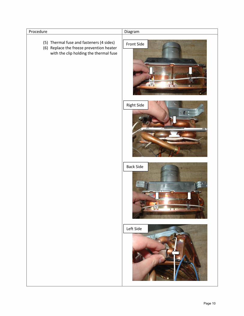
(5) Thermal fuse and fasteners (4 sides) (6) Replace the freeze prevention heater
with the clip holding the thermal fuse
Front Side
Right Side
Back Side
Left Side
Page 10
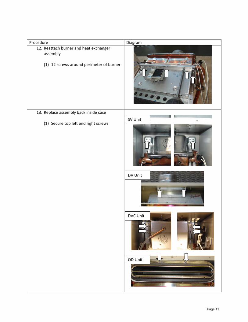
Procedure Diagram 12. Reattach burner and heat exchanger
assembly (1) 12 screws around perimeter of burner
13. Replace assembly back inside case (1) Secure top left and right screws
SV Unit
DV Unit
DVC Unit
OD Unit
Page 11
Procedure Diagram
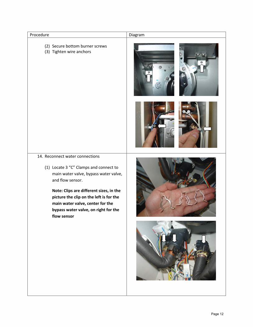
(2) Secure bottom burner screws (3) Tighten wire anchors
14. Reconnect water connections (1) Locate 3 “C” Clamps and connect to
main water valve, bypass water valve, and flow sensor.
Note: Clips are different sizes, in the picture the clip on the left is for the main water valve, center for the bypass water valve, on right for the flow sensor
Page 12

Procedure Diagram 15. Replace gas valve assembly
(1) Secure gas valve assembly to burner
with 4 silver screws (2) Secure manifold pipe to gas inlet
fitting with “C” Clamp. (3) Reconnect large wiring connection,
that attaches the wires from the manifold plate to the wiring harness
(4) DVC UNIT ONLY: Reconnect the rubber tube to the manifold plate
Page 13

Procedure Diagram 16. Replace circuit board and GFCI
(1) Slide circuit back into original position (2) Secure top of circuit board screw (3) Secure bottom of circuit board screw
and ground wire to the left (4) Secure GFCI plate to case with 2
screws (ground wire on right side) (5) DVC UNITS ONLY: Secure the remote
controller back into the unit and reconnect the wire if you removed it
Page 14

Procedure Diagram 17. Reconnect all wires that attach to the
wiring harness and the body of the water heater (1) Wiring for the fan (2) High limit switch, freeze prevention
heater (3) Thermal fuse (2), heat exchanger
thermistor (4) Flame rods (2), ignition box (DVC Units
the ignition box is not located on the ignition plug, there will only be a black wire with a gray tip, reconnect that wire)
(5) Freeze prevention on outlet pipe
Page 15

Procedure Diagram 18. Replace case top covers
OD Units this step is skipped SV Units
(1) Place larger top cover first, then gasket, then smaller cover over flue
(2) Secure top covers with 6 screws
DV Units (1) Place the gasket on first, then
the case cover (2) Secure top cover with 4 screws
DVC Units
(1) Place the 2 tabs in case cover into openings in the top of the case
(2) Secure top cover with 2 screws
19. Replace Front Cover (1) Replace water inlet filter (2) Turn on cold water shut off
valve slowly (check for leaks around “C” Clamps)
(3) If you get leaks shut off water and re-secure “C” Clamps
(4) Turn on gas (check “C” Clamp for leaks)
(5) Secure front cover with 4 screws
(6) Replace water inlet filter (7) Return electrical power to the
unit
SV Unit
DV Unit
DVC Unit
Page 16