
HE SERIES ERV - RenewAire
32
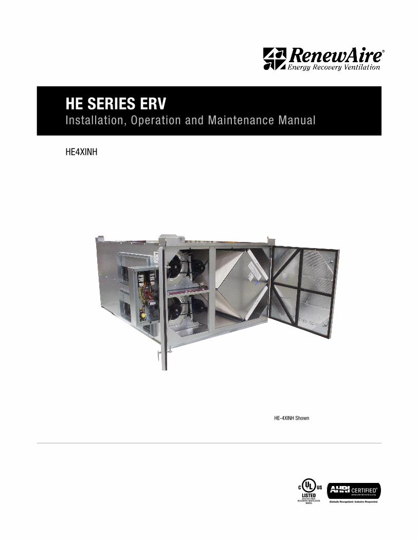
HE4XINH HE SERIES ERV Installation, Operation and Maintenance Manual HE-4XINH Shown
Transcript of HE SERIES ERV - RenewAire
HE4XINH
HE SERIES ERVInstallation, Operation and Maintenance Manual
HE-4XINH Shown
1.800.627.44992
HE-Series IndoorERV
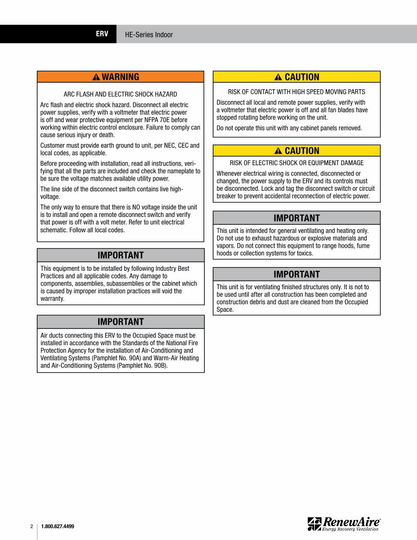
WARNING
ARC FLASH AND ELECTRIC SHOCK HAZARD
Arc flash and electric shock hazard. Disconnect all electric power supplies, verify with a voltmeter that electric power is off and wear protective equipment per NFPA 70E before working within electric control enclosure. Failure to comply can cause serious injury or death.
Customer must provide earth ground to unit, per NEC, CEC and local codes, as applicable.
Before proceeding with installation, read all instructions, veri-fying that all the parts are included and check the nameplate to be sure the voltage matches available utility power.
The line side of the disconnect switch contains live high- voltage.
The only way to ensure that there is NO voltage inside the unit is to install and open a remote disconnect switch and verify that power is off with a volt meter. Refer to unit electrical schematic. Follow all local codes.
RISK OF ELECTRIC SHOCK OR EQUIPMENT DAMAGE
Whenever electrical wiring is connected, disconnected or changed, the power supply to the ERV and its controls must be disconnected. Lock and tag the disconnect switch or circuit breaker to prevent accidental reconnection of electric power.
RISK OF CONTACT WITH HIGH SPEED MOVING PARTS
Disconnect all local and remote power supplies, verify with a voltmeter that electric power is off and all fan blades have stopped rotating before working on the unit.
Do not operate this unit with any cabinet panels removed.
This unit is intended for general ventilating and heating only. Do not use to exhaust hazardous or explosive materials and vapors. Do not connect this equipment to range hoods, fume hoods or collection systems for toxics.
This equipment is to be installed by following Industry Best Practices and all applicable codes. Any damage to components, assemblies, subassemblies or the cabinet which is caused by improper installation practices will void the warranty.
Air ducts connecting this ERV to the Occupied Space must be installed in accordance with the Standards of the National Fire Protection Agency for the installation of Air-Conditioning and Ventilating Systems (Pamphlet No. 90A) and Warm-Air Heating and Air-Conditioning Systems (Pamphlet No. 90B).
This unit is for ventilating finished structures only. It is not to be used until after all construction has been completed and construction debris and dust are cleaned from the Occupied Space.
CAUTION
CAUTION
IMPORTANT
IMPORTANT
IMPORTANT
IMPORTANT
31.800.627.4499
HE-Series Indoor ERV
Serial Number:
SO#:
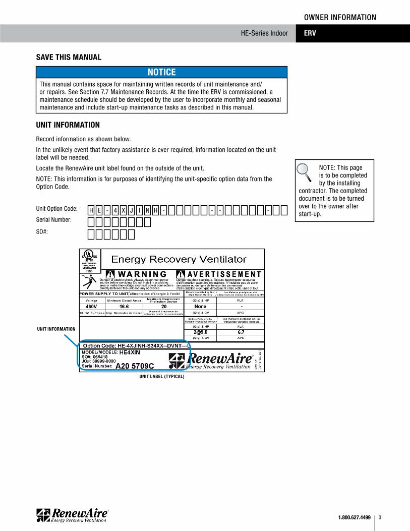
Unit Option Code:
UNIT LABEL (TYPICAL)
UNIT INFORMATION
H X- IE -J -4 N --
SAVE THIS MANUAL
This manual contains space for maintaining written records of unit maintenance and/or repairs. See Section 7.7 Maintenance Records. At the time the ERV is commissioned, a maintenance schedule should be developed by the user to incorporate monthly and seasonal maintenance and include start-up maintenance tasks as described in this manual.
NOTICE
UNIT INFORMATION
Record information as shown below.
In the unlikely event that factory assistance is ever required, information located on the unit label will be needed.
Locate the RenewAire unit label found on the outside of the unit.
NOTE: This information is for purposes of identifying the unit-specific option data from the Option Code.
NOTE: This page is to be completed by the installing
contractor. The completed document is to be turned over to the owner after start-up.
OWNER INFORMATION
H
1.800.627.44994
RENEWAIRE.COM 1.800.627.4499 94
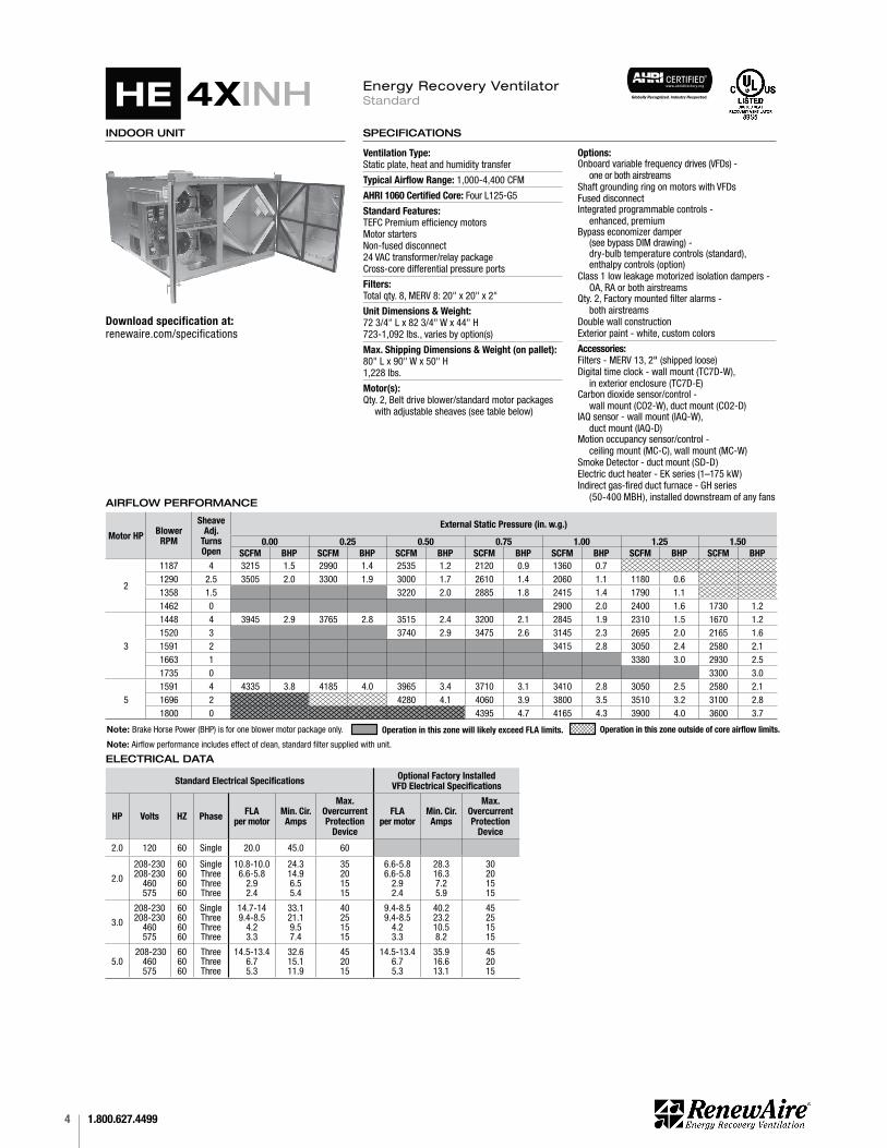
SPECIFICATIONS & DIMENSIONS
Specifi cations may be subject to change without notice.
INDOOR UNIT
Ventilation Type: Static plate, heat and humidity transfer
Typical Airfl ow Range: 1,000-4,400 CFM
AHRI 1060 Certifi ed Core: Four L125-G5
Standard Features:TEFC Premium effi ciency motors Motor startersNon-fused disconnect24 VAC transformer/relay packageCross-core differential pressure ports
Filters: Total qty. 8, MERV 8: 20" x 20" x 2"
Unit Dimensions & Weight:72 3/4" L x 82 3/4" W x 44" H723-1,092 lbs., varies by option(s)
Max. Shipping Dimensions & Weight (on pallet): 80" L x 90" W x 50" H1,228 lbs.
Motor(s): Qty. 2, Belt drive blower/standard motor packages
with adjustable sheaves (see table below)
Options: Onboard variable frequency drives (VFDs) - one or both airstreamsShaft grounding ring on motors with VFDsFused disconnectIntegrated programmable controls - enhanced, premium Bypass economizer damper (see bypass DIM drawing) -
dry-bulb temperature controls (standard),enthalpy controls (option)
Class 1 low leakage motorized isolation dampers - OA, RA or both airstreams
Qty. 2, Factory mounted fi lter alarms - both airstreams Double wall constructionExterior paint - white, custom colors
Accessories:Filters - MERV 13, 2" (shipped loose)Digital time clock - wall mount (TC7D-W),
in exterior enclosure (TC7D-E)Carbon dioxide sensor/control - wall mount (CO2-W), duct mount (CO2-D) IAQ sensor - wall mount (IAQ-W), duct mount (IAQ-D)Motion occupancy sensor/control - ceiling mount (MC-C), wall mount (MC-W)Smoke Detector - duct mount (SD-D)Electric duct heater - EK series (1–175 kW)Indirect gas-fi red duct furnace - GH series
(50-400 MBH), installed downstream of any fans
SPECIFICATIONS
ELECTRICAL DATA
Standard Electrical Specifi cations Optional Factory Installed VFD Electrical Specifi cations
HP Volts HZ Phase FLAper motor
Min. Cir. Amps
Max. Overcurrent Protection
Device
FLAper motor
Min. Cir. Amps
Max. Overcurrent Protection
Device
2.0 120 60 Single 20.0 45.0 60
2.0
208-230208-230
460575
60606060
SingleThreeThreeThree
10.8-10.06.6-5.8
2.92.4
24.314.96.55.4
35201515
6.6-5.86.6-5.8
2.92.4
28.316.37.25.9
30201515
3.0
208-230208-230
460575
60606060
SingleThreeThreeThree
14.7-149.4-8.5
4.23.3
33.121.19.57.4
40251515
9.4-8.59.4-8.5
4.23.3
40.223.210.58.2
45251515
5.0 208-230
460575
606060
ThreeThreeThree
14.5-13.46.75.3
32.615.111.9
452015
14.5-13.46.75.3
35.916.613.1
452015
AIRFLOW PERFORMANCE
Motor HP Blower RPM
Sheave Adj.
Turns Open
External Static Pressure (in. w.g.)
0.00 0.25 0.50 0.75 1.00 1.25 1.50SCFM BHP SCFM BHP SCFM BHP SCFM BHP SCFM BHP SCFM BHP SCFM BHP
2
1187 4 3215 1.5 2990 1.4 2535 1.2 2120 0.9 1360 0.71290 2.5 3505 2.0 3300 1.9 3000 1.7 2610 1.4 2060 1.1 1180 0.61358 1.5 3220 2.0 2885 1.8 2415 1.4 1790 1.11462 0 2900 2.0 2400 1.6 1730 1.2
3
1448 4 3945 2.9 3765 2.8 3515 2.4 3200 2.1 2845 1.9 2310 1.5 1670 1.21520 3 3740 2.9 3475 2.6 3145 2.3 2695 2.0 2165 1.61591 2 3415 2.8 3050 2.4 2580 2.11663 1 3380 3.0 2930 2.51735 0 3300 3.0
51591 4 4335 3.8 4185 4.0 3965 3.4 3710 3.1 3410 2.8 3050 2.5 2580 2.11696 2 4280 4.1 4060 3.9 3800 3.5 3510 3.2 3100 2.81800 0 4395 4.7 4165 4.3 3900 4.0 3600 3.7
Note: Brake Horse Power (BHP) is for one blower motor package only. Operation in this zone will likely exceed FLA limits. Operation in this zone outside of core airfl ow limits.
Note: Airfl ow performance includes effect of clean, standard fi lter supplied with unit.
HE 4XINHHE
Download specification at:renewaire.com/specifications
Energy Recovery VentilatorStandard & Bypass Economizer OptionEnergy Recovery VentilatorStandard

51.800.627.4499
FOR THE MOST COMPLETE AND CURRENT INFORMATION VISIT RENEWAIRE.COM 95
HE-S
ERIE
S
37
3/8"
Typ
.
4 1/2" 21 3/8"
41"Case
79
3/4"
C
L76
" Wiri
ng
RA
34" X
12"
Duc
t Rec
eivi
ngFl
ange
Typ
.
OA
EA FA
10
1/4"
56
7/8"
4 1/
4"
Duc
t Fla
nge
Typ.
5" D
ampe
r Fr
ames
Typ
.
55
7/8"
Lift
ing
Lugs
CL
2 5/
8" C
ontro
l In
C
L5
3/4"
Pow
er In
Pres
sure
Ports
(4) T
yp.
Disc
onne
ctSw
itch
E-Bo
x 1
9 1/
4" T
yp.
6"
24 3/4"
3 3/4" 44"Overall
OA
Inle
t42
" X 1
4"D
uct R
ecei
ving
Fl
ange
RA In
let
42" X
14"
Duc
t Rec
eivi
ng
Flan
ge
RA D
ampe
rLo
catio
n(O
ptio
nal)
OA
Dam
per
Loca
tion
(Opt
iona
l)
57
3/8"
Cas
e
72
3/4"
Ove
rall
82" Case
82 3/4" Overall
67 3
/8" M
inim
umSe
rvic
e A
rea
38 7/8" MinimumService Area
TOP
VIE
W
Doo
rSw
ing
1 1/8
" Typ.
2 1/8
"
Typ.
RIG
HT V
IEW
FRO
NT
VIE
WLE
FT V
IEW
(2)
7/8"
Hol
esfo
r wiri
ng in
botto
m o
f E-B
ox
Doo
rSw
ing
Mod
el: H
E4XI
NH
Dra
win
g Ty
pe: U
nit D
imen
sion
Ver
sion:
MA
Y18
ABB
REVI
ATIO
NS
EA: E
xhau
st A
ir to
out
side
OA
: Out
side
Air
inta
keRA
: Roo
m A
ir to
be
exha
uste
dFA
: Fre
sh A
ir to
insid
e
INST
ALL
ATIO
N O
RIEN
TATIO
NUn
it m
ust b
e in
stal
led
in o
rient
atio
nsh
own.
NO
TE1.
UN
LESS
OTH
ERW
ISE
SPEC
IFIE
D,
DIM
ENSI
ON
S A
RE R
OUN
DED
TO
THE
N
EARE
ST E
IGHT
H O
F A
N IN
CH.
2. S
PEC
IFIC
ATIO
NS
MA
Y BE
SUB
JEC
T TO
CHA
NG
E W
ITHO
UT N
OTIC
E.
3. M
IN. D
UCT
CLE
ARA
NC
EFR
OM
DA
MPE
R BL
AD
ES W
HEN
FUL
LYO
PEN
ED T
O B
E 2"
. SM
AC
NA
RUL
ES
APP
LY.
HE4X
INH
E
ne
rgy R
ec
ove
ry V
en
tila
tor
Sta
nd
ard
AIR
FLO
W C
ON
FIG
UR
ATIO
NAv
aila
ble
as s
how
n in
dim
ensi
on d
raw
ing.
UN
IT M
OU
NTIN
G &
AP
PLIC
ATIO
NM
ust b
e m
ount
ed a
s sh
own.
RA/
EA a
irstre
am c
an
be s
witc
hed
with
OA/
FA a
irstre
am u
nles
s ce
rtain
op
tions
are
sel
ecte
d.
1.800.627.44996
HE-Series IndoorERV
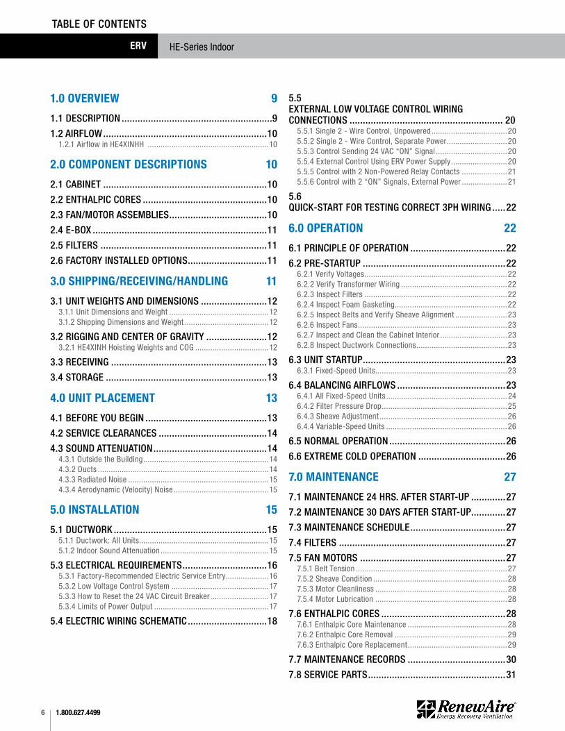
1.0 OVERVIEW 9
1.1 DESCRIPTION .........................................................9
1.2 AIRFLOW ..............................................................101.2.1 Airflow in HE4XINHH ........................................................10
2.0 COMPONENT DESCRIPTIONS 10
2.1 CABINET ..............................................................10
2.2 ENTHALPIC CORES ...............................................10
2.3 FAN/MOTOR ASSEMBLIES .....................................10
2.4 E-BOX ..................................................................11
2.5 FILTERS ...............................................................11
2.6 FACTORY INSTALLED OPTIONS ..............................11
3.0 SHIPPING/RECEIVING/HANDLING 11
3.1 UNIT WEIGHTS AND DIMENSIONS .........................123.1.1 Unit Dimensions and Weight ..............................................123.1.2 Shipping Dimensions and Weight .......................................12
3.2 RIGGING AND CENTER OF GRAVITY .......................123.2.1 HE4XINH Hoisting Weights and COG ..................................12
3.3 RECEIVING ...........................................................13
3.4 STORAGE .............................................................13
4.0 UNIT PLACEMENT 13
4.1 BEFORE YOU BEGIN ..............................................13
4.2 SERVICE CLEARANCES .........................................14
4.3 SOUND ATTENUATION ...........................................144.3.1 Outside the Building ..........................................................144.3.2 Ducts ...............................................................................144.3.3 Radiated Noise .................................................................154.3.4 Aerodynamic (Velocity) Noise ............................................15
5.0 INSTALLATION 15
5.1 DUCTWORK ..........................................................155.1.1 Ductwork: All Units............................................................155.1.2 Indoor Sound Attenuation ..................................................15
5.3 ELECTRICAL REQUIREMENTS ................................165.3.1 Factory-Recommended Electric Service Entry....................165.3.2 Low Voltage Control System .............................................175.3.3 How to Reset the 24 VAC Circuit Breaker ...........................175.3.4 Limits of Power Output .....................................................17
5.4 ELECTRIC WIRING SCHEMATIC ..............................18
5.5 EXTERNAL LOW VOLTAGE CONTROL WIRING CONNECTIONS .......................................................... 20
5.5.1 Single 2 - Wire Control, Unpowered ...................................205.5.2 Single 2 - Wire Control, Separate Power ............................205.5.3 Control Sending 24 VAC “ON” Signal .................................205.5.4 External Control Using ERV Power Supply ..........................205.5.5 Control with 2 Non-Powered Relay Contacts ..................... 215.5.6 Control with 2 “ON” Signals, External Power ..................... 21
5.6 QUICK-START FOR TESTING CORRECT 3PH WIRING .....22
6.0 OPERATION 22
6.1 PRINCIPLE OF OPERATION ....................................22
6.2 PRE-STARTUP ......................................................226.2.1 Verify Voltages ..................................................................226.2.2 Verify Transformer Wiring .................................................226.2.3 Inspect Filters ..................................................................226.2.4 Inspect Foam Gasketing ....................................................226.2.5 Inspect Belts and Verify Sheave Alignment ........................236.2.6 Inspect Fans .....................................................................236.2.7 Inspect and Clean the Cabinet Interior ...............................236.2.8 Inspect Ductwork Connections ..........................................23
6.3 UNIT STARTUP ......................................................236.3.1 Fixed-Speed Units .............................................................23
6.4 BALANCING AIRFLOWS .........................................236.4.1 All Fixed-Speed Units ........................................................ 246.4.2 Filter Pressure Drop ..........................................................256.4.3 Sheave Adjustment ...........................................................266.4.4 Variable-Speed Units ........................................................26
6.5 NORMAL OPERATION ............................................26
6.6 EXTREME COLD OPERATION .................................26
7.0 MAINTENANCE 27
7.1 MAINTENANCE 24 HRS. AFTER START-UP .............27
7.2 MAINTENANCE 30 DAYS AFTER START-UP .............27
7.3 MAINTENANCE SCHEDULE ....................................27
7.4 FILTERS ...............................................................27
7.5 FAN MOTORS .......................................................277.5.1 Belt Tension ......................................................................277.5.2 Sheave Condition ..............................................................287.5.3 Motor Cleanliness .............................................................287.5.4 Motor Lubrication .............................................................28
7.6 ENTHALPIC CORES ...............................................287.6.1 Enthalpic Core Maintenance ..............................................287.6.2 Enthalpic Core Removal ....................................................297.6.3 Enthalpic Core Replacement ..............................................29
7.7 MAINTENANCE RECORDS .....................................30
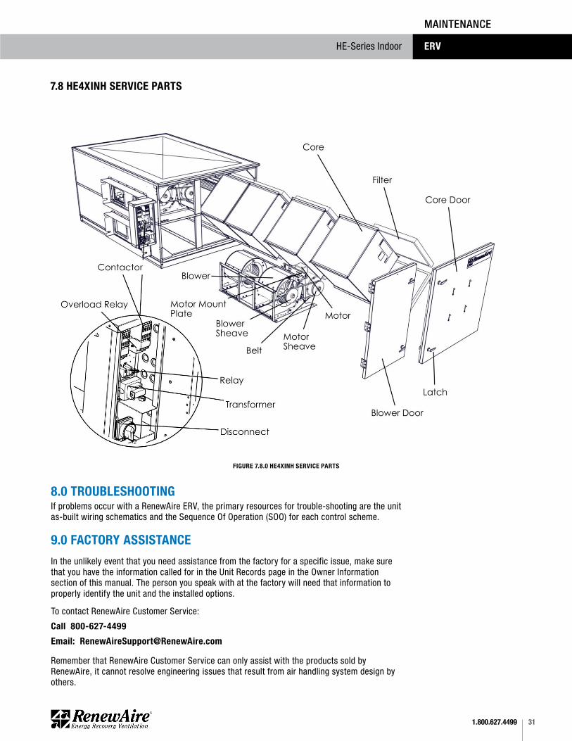
7.8 SERVICE PARTS ....................................................31
TABLE OF CONTENTS
71.800.627.4499
HE-Series Indoor ERV
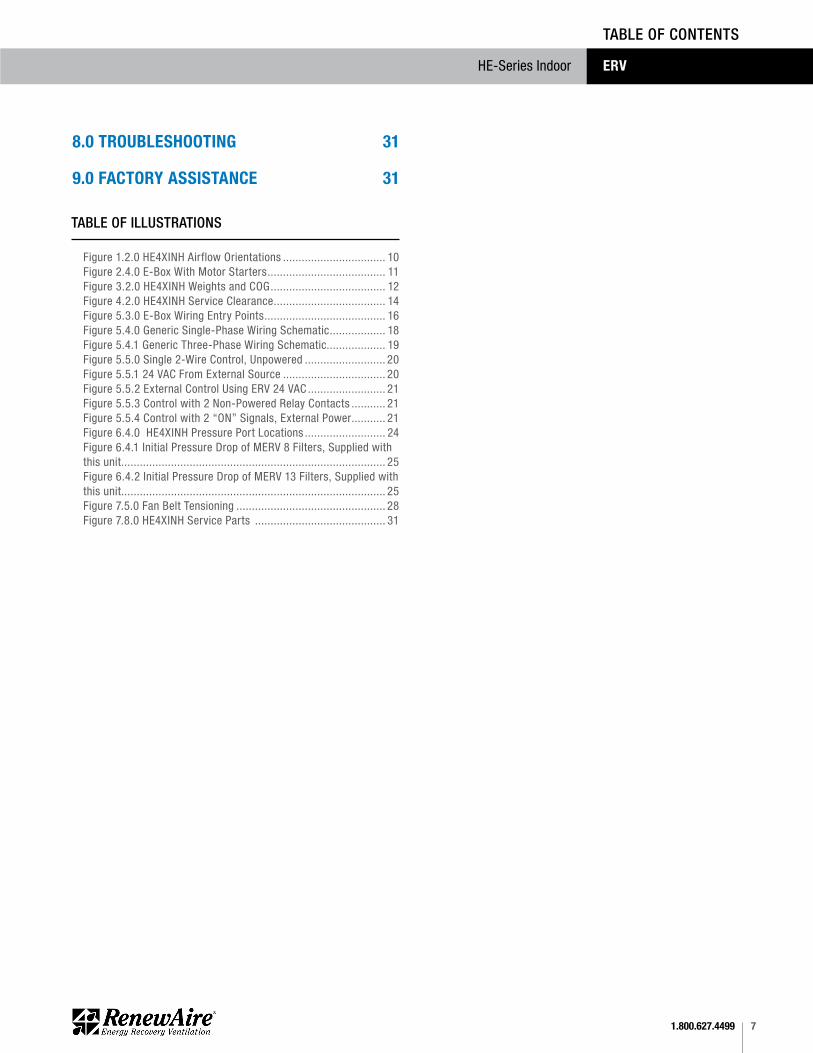
Figure 1.2.0 HE4XINH Airflow Orientations ................................. 10Figure 2.4.0 E-Box With Motor Starters ...................................... 11Figure 3.2.0 HE4XINH Weights and COG ..................................... 12Figure 4.2.0 HE4XINH Service Clearance .................................... 14Figure 5.3.0 E-Box Wiring Entry Points ....................................... 16Figure 5.4.0 Generic Single-Phase Wiring Schematic .................. 18Figure 5.4.1 Generic Three-Phase Wiring Schematic................... 19 Figure 5.5.0 Single 2-Wire Control, Unpowered .......................... 20Figure 5.5.1 24 VAC From External Source ................................. 20Figure 5.5.2 External Control Using ERV 24 VAC ......................... 21Figure 5.5.3 Control with 2 Non-Powered Relay Contacts ........... 21Figure 5.5.4 Control with 2 “ON” Signals, External Power ........... 21Figure 6.4.0 HE4XINH Pressure Port Locations .......................... 24Figure 6.4.1 Initial Pressure Drop of MERV 8 Filters, Supplied with this unit..................................................................................... 25Figure 6.4.2 Initial Pressure Drop of MERV 13 Filters, Supplied with this unit..................................................................................... 25Figure 7.5.0 Fan Belt Tensioning ................................................ 28Figure 7.8.0 HE4XINH Service Parts .......................................... 31
TABLE OF CONTENTS
TABLE OF ILLUSTRATIONS
8.0 TROUBLESHOOTING 31
9.0 FACTORY ASSISTANCE 31
1.800.627.44998
HE-Series IndoorERV
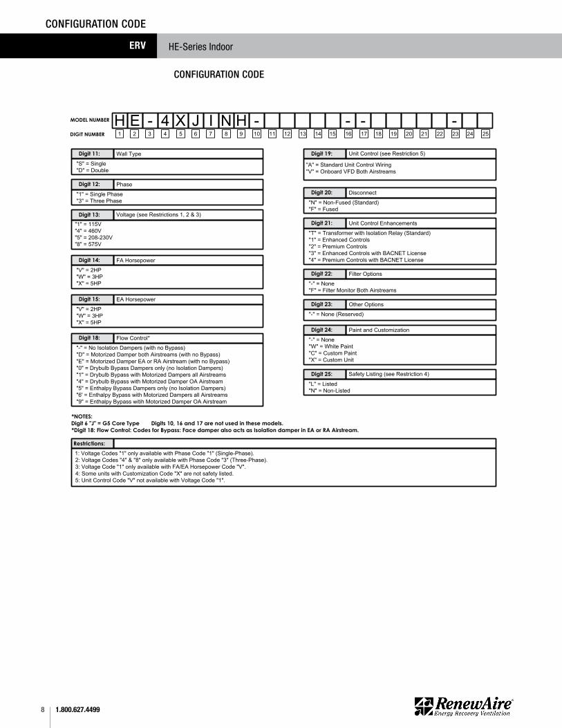
CONFIGURATION CODE
MODEL NUMBER
1 2 3 4 5 6 7 8 9 10 11 12 13 14 15 16 17 18 19 20 21 22 23 24 25
J - - -DIGIT NUMBER
Wall Type Digit 11:
"S" = Single"D" = Double
Phase Digit 12:
"1" = Single Phase"3" = Three Phase
Digit 13:"1" = 115V"4" = 460V"5" = 208-230V"8" = 575V
FA Horsepower Digit 14:"V" = 2HP"W" = 3HP "X" = 5HP
Flow Control* Digit 18: "-" = No Isolation Dampers (with no Bypass)"D" = Motorized Damper both Airstreams (with no Bypass)"E" = Motorized Damper EA or RA Airstream (with no Bypass)"0" = Drybulb Bypass Dampers only (no Isolation Dampers)"1" = Drybulb Bypass with Motorized Dampers all Airstreams"4" = Drybulb Bypass with Motorized Damper OA Airstream"5" = Enthalpy Bypass Dampers only (no Isolation Dampers)"6' = Enthalpy Bypass with Motorized Dampers all Airstreams"9" = Enthalpy Bypass witih Motorized Damper OA Airstream
*NOTES: Digit 6 "J" = G5 Core Type Digits 10, 16 and 17 are not used in these models.*Digit 18: Flow Control: Codes for Bypass: Face damper also acts as Isolation damper in EA or RA Airstream.
Restrictions:1: Voltage Codes "1" only available with Phase Code "1" (Single-Phase).2: Voltage Codes "4" & "8" only available with Phase Code "3" (Three-Phase).3: Voltage Code "1" only available with FA/EA Horsepower Code "V".4: Some units with Customization Code "X" are not safety listed. 5: Unit Control Code "V" not available with Voltage Code "1".
Digit 19:
"A" = Standard Unit Control Wiring"V" = Onboard VFD Both Airstreams
Disconnect Digit 20:
"N" = Non-Fused (Standard)"F" = Fused
Unit Control Enhancements Digit 21:
"T" = Transformer with Isolation Relay (Standard)"1" = Enhanced Controls"2" = Premium Controls"3" = Enhanced Controls with BACNET License"4" = Premium Controls with BACNET License
Filter Options Digit 22:"-" = None"F" = Filter Monitor Both Airstreams
Other Options Digit 23:"-" = None (Reserved)
Paint and Customization Digit 24:"-" = None"W" = White Paint"C" = Custom Paint"X" = Custom Unit
Digit 25:"L" = Listed"N" = Non-Listed
-H E - 4 X I N H
EA Horsepower Digit 15:"V" = 2HP"W" = 3HP "X" = 5HP
Voltage (see Restrictions 1, 2 & 3)
Unit Control (see Restriction 5)
Safety Listing (see Restriction 4)
HE4XINH MODELPRODUCT CODE CHART
CONFIGURATION CODE
91.800.627.4499
HE-Series Indoor ERV
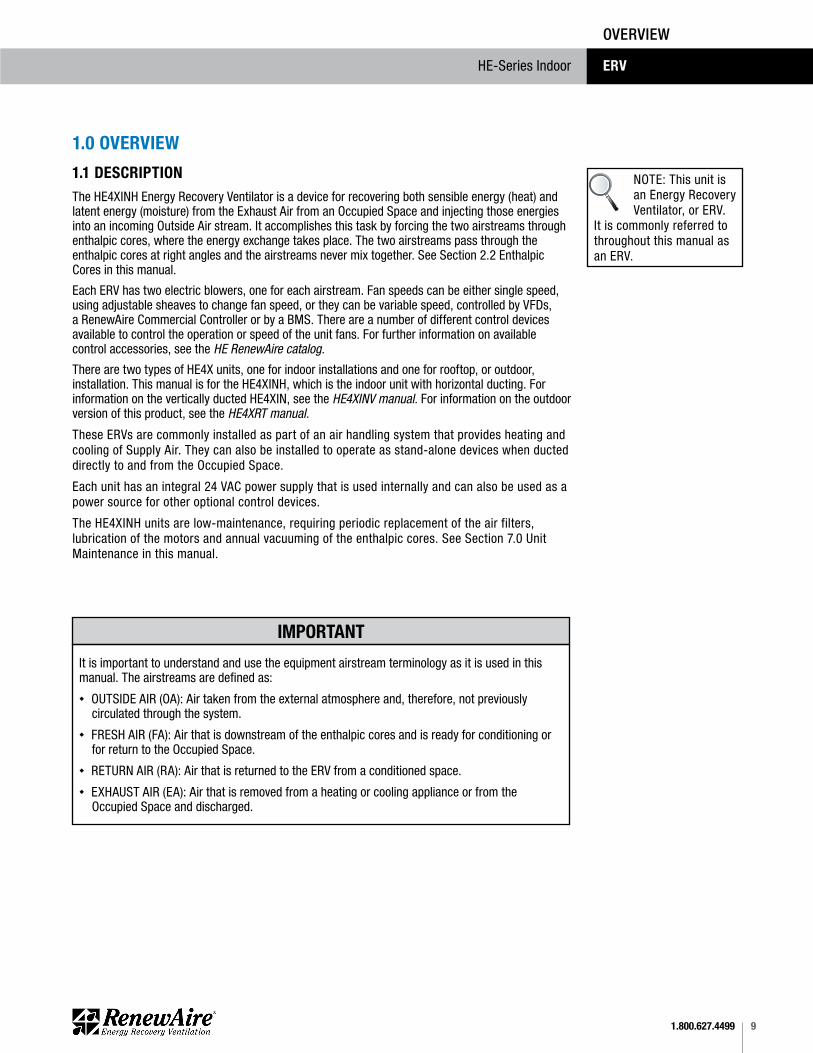
1.0 OVERVIEW
The HE4XINH Energy Recovery Ventilator is a device for recovering both sensible energy (heat) and latent energy (moisture) from the Exhaust Air from an Occupied Space and injecting those energies into an incoming Outside Air stream. It accomplishes this task by forcing the two airstreams through enthalpic cores, where the energy exchange takes place. The two airstreams pass through the enthalpic cores at right angles and the airstreams never mix together. See Section 2.2 Enthalpic Cores in this manual.
Each ERV has two electric blowers, one for each airstream. Fan speeds can be either single speed, using adjustable sheaves to change fan speed, or they can be variable speed, controlled by VFDs, a RenewAire Commercial Controller or by a BMS. There are a number of different control devices available to control the operation or speed of the unit fans. For further information on available control accessories, see the HE RenewAire catalog.
There are two types of HE4X units, one for indoor installations and one for rooftop, or outdoor, installation. This manual is for the HE4XINH, which is the indoor unit with horizontal ducting. For information on the vertically ducted HE4XIN, see the HE4XINV manual. For information on the outdoor version of this product, see the HE4XRT manual.
These ERVs are commonly installed as part of an air handling system that provides heating and cooling of Supply Air. They can also be installed to operate as stand-alone devices when ducted directly to and from the Occupied Space.
Each unit has an integral 24 VAC power supply that is used internally and can also be used as a power source for other optional control devices.
The HE4XINH units are low-maintenance, requiring periodic replacement of the air filters, lubrication of the motors and annual vacuuming of the enthalpic cores. See Section 7.0 Unit Maintenance in this manual.
1.1 DESCRIPTION
IMPORTANT
It is important to understand and use the equipment airstream terminology as it is used in this manual. The airstreams are defined as:u OUTSIDE AIR (OA): Air taken from the external atmosphere and, therefore, not previously circulated through the system. u FRESH AIR (FA): Air that is downstream of the enthalpic cores and is ready for conditioning or for return to the Occupied Space. u RETURN AIR (RA): Air that is returned to the ERV from a conditioned space. u EXHAUST AIR (EA): Air that is removed from a heating or cooling appliance or from the Occupied Space and discharged.
OVERVIEW
NOTE: This unit is an Energy Recovery Ventilator, or ERV.
It is commonly referred to throughout this manual as an ERV.
1.800.627.449910
HE-Series IndoorERV
OVERVIEW
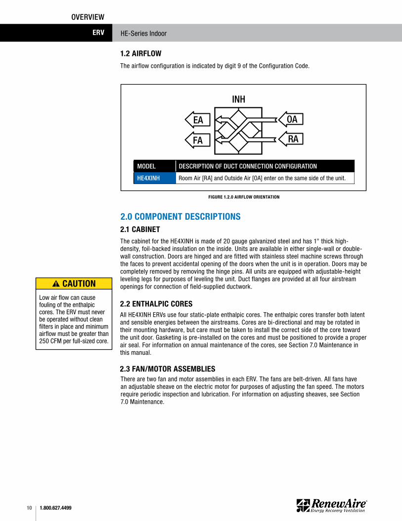
MODEL DESCRIPTION OF DUCT CONNECTION CONFIGURATION
HE4XINH Room Air [RA] and Outside Air [OA] enter on the same side of the unit.
FA
OA
RA
EA
HEIN except 6x 8x, LE_IN
INH
FIGURE 1.2.0 AIRFLOW ORIENTATION
2.0 COMPONENT DESCRIPTIONS
2.2 ENTHALPIC CORES
2.1 CABINET
All HE4XINH ERVs use four static-plate enthalpic cores. The enthalpic cores transfer both latent and sensible energies between the airstreams. Cores are bi-directional and may be rotated in their mounting hardware, but care must be taken to install the correct side of the core toward the unit door. Gasketing is pre-installed on the cores and must be positioned to provide a proper air seal. For information on annual maintenance of the cores, see Section 7.0 Maintenance in this manual.
The cabinet for the HE4XINH is made of 20 gauge galvanized steel and has 1" thick high-density, foil-backed insulation on the inside. Units are available in either single-wall or double-wall construction. Doors are hinged and are fitted with stainless steel machine screws through the faces to prevent accidental opening of the doors when the unit is in operation. Doors may be completely removed by removing the hinge pins. All units are equipped with adjustable-height leveling legs for purposes of leveling the unit. Duct flanges are provided at all four airstream openings for connection of field-supplied ductwork.
2.3 FAN/MOTOR ASSEMBLIESThere are two fan and motor assemblies in each ERV. The fans are belt-driven. All fans have an adjustable sheave on the electric motor for purposes of adjusting the fan speed. The motors require periodic inspection and lubrication. For information on adjusting sheaves, see Section 7.0 Maintenance.
Low air flow can cause fouling of the enthalpic cores. The ERV must never be operated without clean filters in place and minimum airflow must be greater than 250 CFM per full-sized core.
CAUTION
The airflow configuration is indicated by digit 9 of the Configuration Code.
1.2 AIRFLOW
111.800.627.4499
HE-Series Indoor ERV
2.4 E-BOXEvery HE4XINH is equipped with what is known as an “E-Box.” High-voltage supply wiring and low-voltage control wiring is all terminated here. When VFDs are installed in the unit, the VFD keypads are installed here. If optional integrated programmable controls are installed, an additional 24 VAC transformer is installed here to power both the controller and its dedicated sensors.
FIGURE 2.4.0 E-BOX WITH MOTOR STARTERS
NOTE: Every ERV has an attached electrical connec-tion box, known as
the E-Box. It is attached to the outside of the ERV and all electrical connections are made there. There is a high-voltage side and a low-voltage side. See Figure 2.4.0.
COMPONENTS
2.5 FILTERSAll HE4XINH units come equipped with eight each MERV 8 20" X 20" X 2" thick pleated paper filters. MERV 13 filters can be ordered as an accessory and are shipped loose.
2.6 FACTORY INSTALLED OPTIONSAll HE4XINH units can be ordered with factory installed options. See Unit Configuration Code on page 8.
Options will have supplemental manuals shipped with the unit.
For Isolation Dampers, see Isolation Dampers Supplemental Manual.
For Commercial Controls, see Commercial Controls Supplemental Manual.
For Filter Alarm, see Filter Alarm Supplemental Manual.
For Economizer/Bypass, see Bypass Economizer Supplemental Manual.
For Isolation Dampers, see Isolation Dampers Supplemental Manual.
For Variable Frequency Drive, see VFD Supplemental Manual.
3.0 SHIPPING/RECEIVING/HANDLINGHE4XINH units are palletized at the factory and then shipped by common carrier. Upon receipt by the installer, the shipment should be inspected for shipping damage, prior to unloading. Any discovered shipping damage should be immediately reported to the RenewAire sales rep and the damage must be recorded on the Bill Of Lading, prior to signing for acceptance of the shipment. The unit can be handled with a fork lift or a crane. Prior to moving the unit, verify that all latches and securing bolts on the cabinet doors are tightly fastened.
www.renewaire.com (800) 627- 4499 [email protected]
GROUND BUS
DISCONNECT SWITCH
POWER SUPPLY WIRING CONNECTED HERE ON TOP OF DISCONNECT SWITCH
OPTIONAL UNIT FUSING
www.renewaire.com (800) 627- 4499 [email protected]
24 VAC STEP-DOWN TRANSFORMER (WITH BUILT-IN CIRCUIT BREAKER)
LOW-VOLTAGE TERMINAL STRIP (ALL CONTROL WIRING IS CONNECTED HERE)
1.800.627.449912
HE-Series IndoorERV
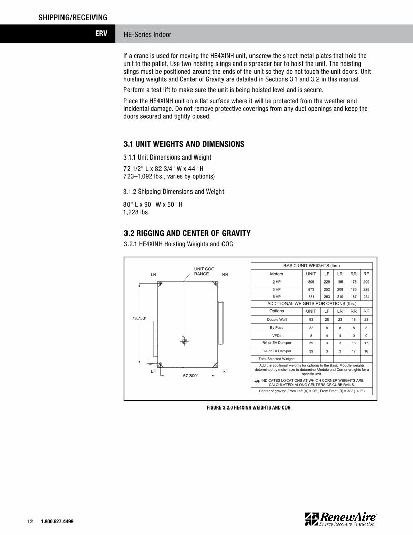
If a crane is used for moving the HE4XINH unit, unscrew the sheet metal plates that hold the unit to the pallet. Use two hoisting slings and a spreader bar to hoist the unit. The hoisting slings must be positioned around the ends of the unit so they do not touch the unit doors. Unit hoisting weights and Center of Gravity are detailed in Sections 3.1 and 3.2 in this manual.
Perform a test lift to make sure the unit is being hoisted level and is secure.
Place the HE4XINH unit on a flat surface where it will be protected from the weather and incidental damage. Do not remove protective coverings from any duct openings and keep the doors secured and tightly closed.
3.1 UNIT WEIGHTS AND DIMENSIONS
3.1.1 Unit Dimensions and Weight
72 1/2" L x 82 3/4" W x 44" H 723–1,092 lbs., varies by option(s)
80" L x 90" W x 50" H 1,228 lbs.
3.1.2 Shipping Dimensions and Weight
SHIPPING/RECEIVING
3.2.1 HE4XINH Hoisting Weights and COG
4/19/07 MFSPECIFICATIONS SUBJECT
TO CHANGE WITHOUT NOTICE.
RenewAire LLC
Scale: 1" = 24"
Do not scale drawing
HE4XH_CORNER_WEIGHTS_APR20.dwg
HE4XINH Corner Weights
LR RR
LF RF
BASIC UNIT WEIGHTS (lbs.)
Motors UNIT LF LR RR RF
2 HP 809 229 195 176 209
3 HP 873 252 208 185 228
5 HP 881 253 210 187 231
ADDITIONAL WEIGHTS FOR OPTIONS (lbs.)
Options UNIT LF LR RR RF
Double Wall 93 28 23 18 23
By-Pass 32 8 8 8 8
VFDs 8 4 4 0 0
RA or EA Damper 39 3 3 16 17
OA or FA Damper 39 3 3 17 16
Total Selected Weights
Add the additional weights for options to the Basic Module weights
determined by motor size to determine Module and Corner weights for a
specific unit.
INDICATES LOCATIONS AT WHICH CORNER WEIGHTS ARE
CALCULATED: ALONG CENTERS OF CURB RAILS.
Center of gravity: From Left (A) = 26", From Front (B) = 33" (+/- 2")
MAY18 MHK
1/3/19 MHZ
APR20 KMC
UNIT COG
RANGE
78.750"
57.300"
FIGURE 3.2.0 HE4XINH WEIGHTS AND COG
3.2 RIGGING AND CENTER OF GRAVITY

131.800.627.4499
HE-Series Indoor ERV
3.3 RECEIVINGUpon receipt of the HE4XINH, inspect the unit for obvious external damage. If damage is observed, take digital pictures and report the damage to your RenewAire rep. Note the damage on the carrier’s Bill of Lading. Depending on expected transport and storage conditions, the unit may have only the duct openings covered, it may be stretch-wrapped or it may be crated. Do not unwrap the unit at this time. The unit will normally be moved to its final location while still wrapped and attached to its pallet.
The preferred method of hoisting the HE4XINH from the carrier truck is by using a construction forklift.
Once the unit is unwrapped, prevent dirt and debris from entering the cabinet by covering any duct openings that do not have attached dampers. Keep the duct openings covered until it’s time to connect ductwork.
SHIPPING/RECEIVING
3.4 HANDLING AND STORAGEUnits that must be stored prior to installation should be left on their pallets and protected from weather and physical damage. Units must be placed on a level surface to prevent wracking of the pallet and the HE4XINH. All access doors must be secured with all available hardware (door latches and securing bolts) and all openings into the cabinet must be sealed to prevent entry of dust, dirt and debris.
4.0 UNIT PLACEMENT4.1 BEFORE YOU BEGINUnits that must be stored prior to installation should be left on their pallets and protected from weather and physical damage. Units must be placed on a level surface to prevent wracking of the pallet and the HE4XINH. All access doors must be secured with all available hardware (door latches and securing bolts) and all openings into the cabinet must be sealed to prevent entry of dust, dirt and debris.
The HE4XINH is designed for installation in a sheltered location, out of the weather. The preferred mounting location is to place the unit on a concrete floor.
1.800.627.449914
HE-Series IndoorERV
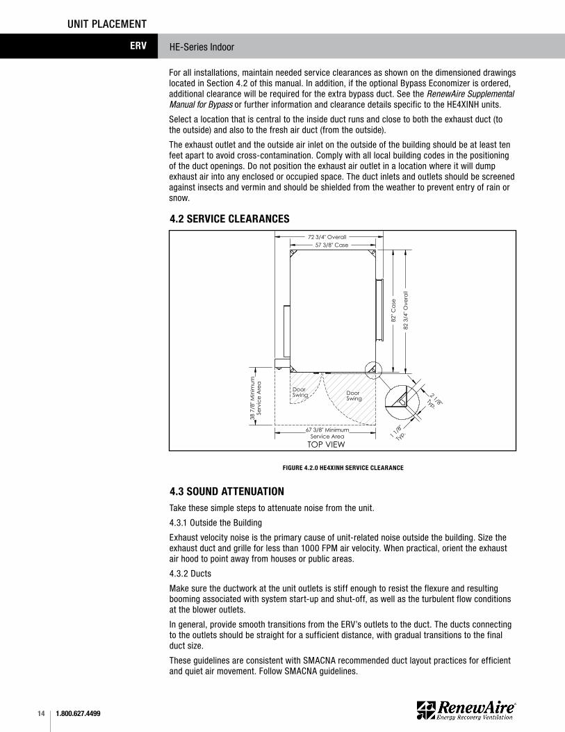
For all installations, maintain needed service clearances as shown on the dimensioned drawings located in Section 4.2 of this manual. In addition, if the optional Bypass Economizer is ordered, additional clearance will be required for the extra bypass duct. See the RenewAire Supplemental Manual for Bypass or further information and clearance details specific to the HE4XINH units.
Select a location that is central to the inside duct runs and close to both the exhaust duct (to the outside) and also to the fresh air duct (from the outside).
The exhaust outlet and the outside air inlet on the outside of the building should be at least ten feet apart to avoid cross-contamination. Comply with all local building codes in the positioning of the duct openings. Do not position the exhaust air outlet in a location where it will dump exhaust air into any enclosed or occupied space. The duct inlets and outlets should be screened against insects and vermin and should be shielded from the weather to prevent entry of rain or snow.
UNIT PLACEMENT
4.2 SERVICE CLEARANCES
37 3/8" Typ.
4 1
/2"
21
3/8"
41"
Cas
e
79 3/4" CL 76" Wiring
RA
34" X 12"Duct ReceivingFlange Typ.
OAEA
FA
10 1/4"
56 7/8"
4 1/4" Duct Flange
Typ.
5" Damper Frames Typ.
55 7/8" Lifting Lugs
CL 2 5/8" Control In CL 5 3/4" Power In
PressurePorts (4) Typ.
DisconnectSwitch
E-Box 19 1/4" Typ.
6"
24
3/4"
3 3
/4"
44"
Ove
rall
OA Inlet42" X 14"Duct Receiving Flange
RA Inlet42" X 14"
Duct Receiving Flange
RA DamperLocation(Optional)
OA DamperLocation(Optional)
57 3/8" Case 72 3/4" Overall
82"
Cas
e
82
3/4"
Ove
rall
67 3/8" MinimumService Area
38 7
/8" M
inim
umSe
rvic
e A
rea
TOP VIEW
DoorSwing
1 1/8
"
Typ.
2 1/8"Typ.
RIGHT VIEWFRONT VIEWLEFT VIEW
(2) 7/8" Holesfor wiring inbottom of E-Box
DoorSwing
Model: HE4XINHDrawing Type: Unit DimensionVersion: MAY18
ABBREVIATIONSEA: Exhaust Air to outsideOA: Outside Air intakeRA: Room Air to be exhaustedFA: Fresh Air to inside
INSTALLATION ORIENTATIONUnit must be installed in orientationshown.
NOTE1. UNLESS OTHERWISE SPECIFIED,DIMENSIONS ARE ROUNDED TO THE NEAREST EIGHTH OF AN INCH.
2. SPECIFICATIONS MAY BE SUBJECT TO CHANGE WITHOUT NOTICE.
3. MIN. DUCT CLEARANCEFROM DAMPER BLADES WHEN FULLYOPENED TO BE 2". SMACNA RULES APPLY.
FIGURE 4.2.0 HE4XINH SERVICE CLEARANCE
4.3 SOUND ATTENUATION Take these simple steps to attenuate noise from the unit.
4.3.1 Outside the Building
Exhaust velocity noise is the primary cause of unit-related noise outside the building. Size the exhaust duct and grille for less than 1000 FPM air velocity. When practical, orient the exhaust air hood to point away from houses or public areas.
4.3.2 Ducts
Make sure the ductwork at the unit outlets is stiff enough to resist the flexure and resulting booming associated with system start-up and shut-off, as well as the turbulent flow conditions at the blower outlets.
In general, provide smooth transitions from the ERV’s outlets to the duct. The ducts connecting to the outlets should be straight for a sufficient distance, with gradual transitions to the final duct size.
These guidelines are consistent with SMACNA recommended duct layout practices for efficient and quiet air movement. Follow SMACNA guidelines.
151.800.627.4499
HE-Series Indoor ERV
INSTALLATION
5.0 INSTALLATION
5.2 FLOOR INSTALLATIONMost units are installed in a location specified by others. In general, it’s preferable to install the unit on a flat, reasonably level surface, such as a concrete floor.
4.3.3 Radiated Noise
The HE4XINH is insulated with high-density fiberglass. This provides significant attenuation of radiated sound.
The outlet ducts can be significant sources of radiated sound as well. The FA and EA ducts (outlet ducts) should be insulated for sound control. This insulation should start at the unit. At a minimum the first ten feet of duct should be insulated. All parts of the FA and EA ducts located in the mechanical space should be insulated for sound control, both to minimize sound radiation out of these ducts and also to control sound radiation into the ducts. 4.3.4 Aerodynamic (Velocity) Noise
When sound attenuation is a design concern, the primary consideration is velocity noise at the unit’s Fresh Air blower outlet. The average velocity at the Fresh Air blower outlet is 2984 FPM when the unit is operating at 3000 CFM.
5.1 DUCTWORK5.1.1 Ducts to the Outside
The exhaust outlet and fresh air inlet on the outside of the building should be at least 10' apart to avoid cross-contamination. The exhaust outlet should not dump air into an enclosed space or any other structure. The inlets and outlets should be screened against insects and vermin and shielded from the weather to prevent the entry of rain or snow.
Ducts connecting the HE4XINH to the outside must be insulated, with sealed vapor barrier on both inside and outside of the insulation. Insulate both the Outside Air (OA) and Exhaust Air (EA) ducts. 5.1.2 Inside Ductwork System
Ensure Good Ductwork Design
Ductwork should be designed to allow the unit to provide the required airflow and reduce pressure drop for efficient, quiet operation. If the inside ducts run through unconditioned spaces they must be insulated with a sealed vapor barrier on both inside and outside of insulation.
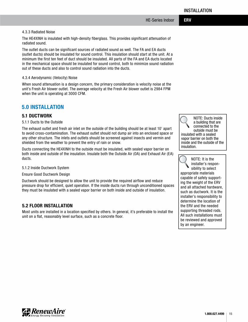
NOTE: Ducts inside a building that are connected to the outside must be
insulated with a sealed vapor barrier on both the inside and the outside of the insulation.
NOTE: It is the installer’s respon-sibility to select
appropriate materials capable of safely support-ing the weight of the ERV and all attached hardware, such as ductwork. It is the installer’s responsibility to determine the location of the ERV and the needed supporting threaded rods. All such installations must be reviewed and approved by an engineer.
1.800.627.449916
HE-Series IndoorERV
INSTALLATION
5.3 ELECTRICAL REQUIREMENTS
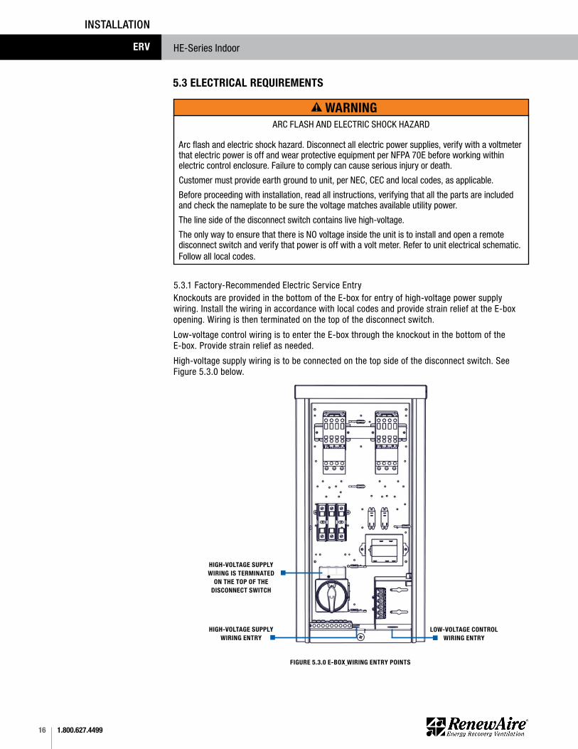
5.3.1 Factory-Recommended Electric Service EntryKnockouts are provided in the bottom of the E-box for entry of high-voltage power supply wiring. Install the wiring in accordance with local codes and provide strain relief at the E-box opening. Wiring is then terminated on the top of the disconnect switch.
Low-voltage control wiring is to enter the E-box through the knockout in the bottom of the E-box. Provide strain relief as needed.
High-voltage supply wiring is to be connected on the top side of the disconnect switch. See Figure 5.3.0 below.
ARC FLASH AND ELECTRIC SHOCK HAZARD
Arc flash and electric shock hazard. Disconnect all electric power supplies, verify with a voltmeter that electric power is off and wear protective equipment per NFPA 70E before working within electric control enclosure. Failure to comply can cause serious injury or death.
Customer must provide earth ground to unit, per NEC, CEC and local codes, as applicable.
Before proceeding with installation, read all instructions, verifying that all the parts are included and check the nameplate to be sure the voltage matches available utility power.
The line side of the disconnect switch contains live high-voltage.
The only way to ensure that there is NO voltage inside the unit is to install and open a remote disconnect switch and verify that power is off with a volt meter. Refer to unit electrical schematic.Follow all local codes.
FIGURE 5.3.0 E-BOX WIRING ENTRY POINTS
WARNING
www.renewaire.com (800) 627- 4499 [email protected]
HIGH-VOLTAGE SUPPLY WIRING ENTRY
HIGH-VOLTAGE SUPPLY WIRING IS TERMINATED
ON THE TOP OF THE DISCONNECT SWITCH
LOW-VOLTAGE CONTROL WIRING ENTRY
171.800.627.4499
HE-Series Indoor ERV
INSTALLATION
If primary-side voltage is 230 VAC, move black primary-side lead from transformer’s “208 V” terminal to the transform-er’s terminal marked “240 V” (“230 V” in some units). Do not move the black primary-side lead that is connected to the trans-former’s “COM” terminal.
NOTICE5.3.2 Low Voltage Control System
This ERV is provided with a Class II 24 VAC power supply system that operates the unit’s contactor(s) for HE4XINH. The ERV’s 24 VAC Power Supply can also be used to power the externally-installed controls system: up to 8VA of power is available.
The unit’s power supply system includes isolation relay(s) so you can use external controls whose contact ratings are as low as 50 mA (1.2 VA). Also, it is possible to operate the isolation relays with 24 VAC power from an external source (with proper wiring connections).
A built-in circuit-breaker prevents damage to the transformer and other low-voltage components in the event of a short-circuit or overload. In extreme cases, the transformer itself is designed to fail safely.
Specifications: u Nominal Output Voltage under load: 24 VACu Typical Output Voltage at no load: 29–31 Vu Minimum contact rating for connected control device: 50 mA (1.2 VA)u Circuit Breaker Trip Point: 3 A
5.3.3 How to Reset the 24 VAC Circuit Breaker
If the transformer is subjected to an excessive load or a short circuit, the circuit breaker will trip to prevent the failure of the transformer. When it trips the circuit breaker’s button pops up. Shut off the primary-side power to the unit, and remove the excessive load or the short. The circuit breaker can be reset about fifteen seconds after it trips by pressing in the button.
Wire Gauge #22 #20 #18 #16 #14 #12
Circuit Length 100' 150' 250' 400' 700' 1000'
“Circuit Length” is distance from ERV to Control Device. Observe these limits to wire length and gauge in order to ensure reliable operation of the control system.
5.3.4 Limits of Power Output
If limits on wire gauge and length are observed, you may connect control devices that draw up to 8 VA to the blue and red wires. More than one device can be connected as long as total steady-state load does not exceed 8 VA.
Be careful if the external control system provides 24 VAC power at its control output: make sure blue and red leads are sep-arately capped and not connected to any other wires.
CAUTION
1. Connect only to components intended for use with 24 VAC power.
2. Do not undersize the low-voltage wires connected to this device. Observe the wire length and gauge limits indicated in this manual.
3. Do not overload this unit’s 24 VAC power supply system. Confirm that the power require-ments of devices you connect to this power supply system do not exceed 8 VA in total.
4. If an external source of 24 VAC power is used to control the unit, consult the wiring schematics and connect the external power only to the specified terminals in order to avoid damaging the unit or external controls. Connect only CLASS II power to the control terminals of this unit.
5. Unit is not equipped to receive analog signals (such as 1–10 vdc or 4–20 mA).
CAUTION

1.800.627.449918
HE-Series IndoorERV
5.4 WIRING SCHEMATICS
CH
AN
GES
NAM
EREV.
DATE
Desc
ription
Fam
ily
Config
No D
am
persRenew
Aire
1
AB
CD
E
New
011/1
3/2
017
aust
ine
15/1
8/2
018
aust
ine
Update
d w
ire c
olo
rs
28/9
/2018
aust
ine
Added W
ire C
olo
r La
bels
HE-2
_H
E-4
XJx
xx-x
11,1
5xx
--xA
xTx-
xx
2 3 4 5 6 7 8 9
10
11
12
13
HE-2
_H
E-4
XJx
xx-x
11,1
5xx
---A
xTx-
xx_002
1 2 3 4 5
Conta
ctor
Overload
24 V
AC
A1
A2
95
96
1L1
3L2
5L3
2T1
4T2
6T3
Exhaust
Conta
ctor
Overload
24 V
AC
A1
A2
95
96
1L1
3L2
5L3
2T1
4T2
6T3
Supply
M Supply
Fan
Exh
aust
Fan
GN
DL3
L2L1In
put
Pow
er
115 V
AC, 1 P
hase
208-2
30 V
AC, 1 P
hase
Tra
nsf
orm
er
CO
M24V
F1
Rela
y
24 V
AC
13
14
812
4Exhaust
Rela
y
24 V
AC
13
14
812
4Supply
RD
RD
BU
BU
BK
BK
RD
RD RD
RD
RD
RD
RD
BU
BU
BU
BU
YL
RD
RD
YL
YL
FIGURE 5.4.0 GENERIC SINGLE-PHASE WIRING SCHEMATIC
191.800.627.4499
HE-Series Indoor ERV
CH
AN
GES
NAM
EREV.
DATE
Desc
ription
Fam
ily
Config
No D
am
persRenew
Aire
1
AB
CD
E
New
03/1
9/2
018
aust
ine
16/1
5/2
018
aust
ine
Update
d W
ire C
olo
rs
212/1
8/2
018
aust
ine
Added W
ire C
olo
r La
bels
HE-2
_H
E-8
XJx
xx-x
34,3
5xx
--xA
xTx-
xx
2 3 4 5 6 7 8 9
10
11
12
13
HE-2
_H
E-8
XJx
xx-x
34,3
5xx
---A
xTx-
xx_002
Conta
ctor
Overload
24 V
AC
A1
A2
95
96
1L1
3L2
5L3
2T1
4T2
6T3
Exhaust
Conta
ctor
Overload
24 V
AC
A1
A2
95
96
1L1
3L2
5L3
2T1
4T2
6T3
Supply
M
Supply
Fan
M
Exh
aust
Fan
GN
DL3
L2L1
Tra
nsf
orm
er
CO
M24V
F1
Input
Pow
er
208-2
30 V
AC, 3 P
hase
460 V
AC, 3 P
hase
1 2 3 4 5
Rela
y
24 V
AC
13
14
812
4Supply
Tra
nsf
orm
er
CO
M24V
Rela
y
24 V
AC
13
14
812
4Exhaust
Conta
ctor
Overload
24 V
AC
A1
A2
95
96
1L1
3L2
5L3
2T1
4T2
6T3
Supply
RD
BU
RD
BU
YL
YL
RD
YL
BU
RD
YL
BU
RD
BU
BK
BK
YL
YL
YL
YL
BU
RD
RD
RD
RD
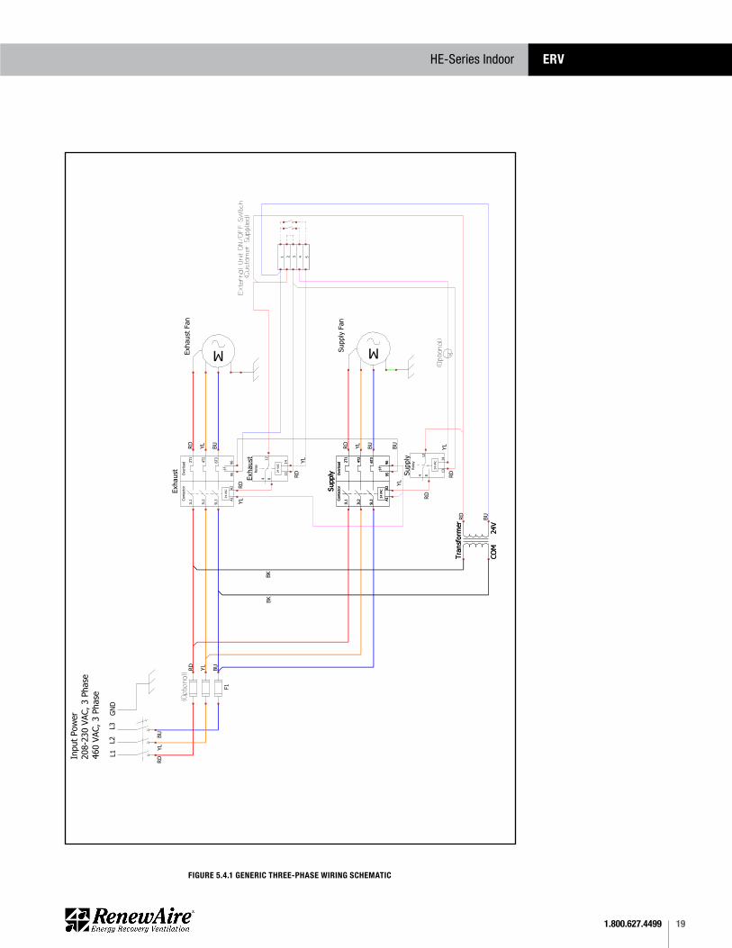
FIGURE 5.4.1 GENERIC THREE-PHASE WIRING SCHEMATIC
1.800.627.449920
HE-Series IndoorERV
INSTALLATION
5.5 EXTERNAL CONTROL CONNECTIONS
FIGURE 5.5.0 SINGLE 2-WIRE CONTROL, UNPOWERED
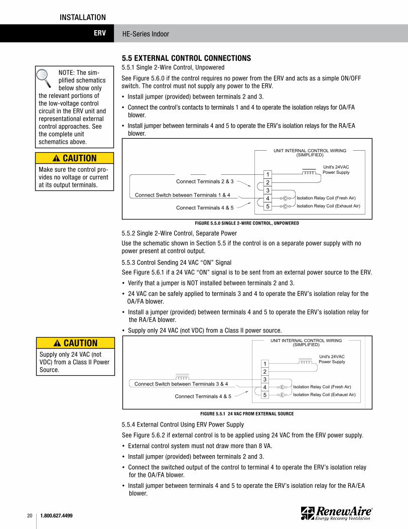
See Figure 5.6.0 if the control requires no power from the ERV and acts as a simple ON/OFF switch. The control must not supply any power to the ERV. u Install jumper (provided) between terminals 2 and 3. u Connect the control’s contacts to terminals 1 and 4 to operate the isolation relays for OA/FA blower.u Install jumper between terminals 4 and 5 to operate the ERV’s isolation relays for the RA/EA blower.
Connect Terminals 2 & 3
Connect Switch between Terminals 1 & 4
UNIT INTERNAL CONTROL WIRING(SIMPLIFIED)
A SWITCH OR NON-POWERED
CONTROL USING UNIT'S 24VAC POWER
SUPPLY
1
2
3
4
5
Unit's 24VAC
Power Supply
C Isolation Relay Coil (Fresh Air)
C Isolation Relay Coil (Exhaust Air)Connect Terminals 4 & 5
Image A from Filename: Control Connections HE2XRT and larger
JUL14.dwg
Friedlander
5/5/2011
Use the schematic shown in Section 5.5 if the control is on a separate power supply with no power present at control output.
See Figure 5.6.1 if a 24 VAC “ON” signal is to be sent from an external power source to the ERV. u Verify that a jumper is NOT installed between terminals 2 and 3. u 24 VAC can be safely applied to terminals 3 and 4 to operate the ERV’s isolation relay for the OA/FA blower. u Install a jumper (provided) between terminals 4 and 5 to operate the ERV’s isolation relay for the RA/EA blower.u Supply only 24 VAC (not VDC) from a Class II power source.
UNIT INTERNAL CONTROL WIRING(SIMPLIFIED)
24VAC FROM AN EXTERNAL SOURCE
1
2
3
4
5
Unit's 24VAC
Power Supply
C Isolation Relay Coil (Fresh Air)
C Isolation Relay Coil (Exhaust Air)
Connect Switch between Terminals 3 & 4
Connect Terminals 4 & 5
Image C from Filename: Control Connections HE2XRT and larger
JUL14.dwg
Friedlander
5/5/2011
FIGURE 5.5.1 24 VAC FROM EXTERNAL SOURCE
5.5.1 Single 2-Wire Control, Unpowered
5.5.2 Single 2-Wire Control, Separate Power
5.5.3 Control Sending 24 VAC “ON” Signal
See Figure 5.6.2 if external control is to be applied using 24 VAC from the ERV power supply.u External control system must not draw more than 8 VA.u Install jumper (provided) between terminals 2 and 3.u Connect the switched output of the control to terminal 4 to operate the ERV’s isolation relay for the OA/FA blower. u Install jumper between terminals 4 and 5 to operate the ERV’s isolation relay for the RA/EA blower.
5.5.4 External Control Using ERV Power Supply
NOTE: The sim-plified schematics below show only
the relevant portions of the low-voltage control circuit in the ERV unit and representational external control approaches. See the complete unit schematics above.
Make sure the control pro-vides no voltage or current at its output terminals.
CAUTION
Supply only 24 VAC (not VDC) from a Class II Power Source.
CAUTION

211.800.627.4499
HE-Series Indoor ERV
INSTALLATION
FIGURE 5.5.2 EXTERNAL CONTROL USING ERV 24 VAC
Unit's 24VAC
Power Supply
UNIT INTERNAL CONTROL WIRING(SIMPLIFIED)
AN EXTERNAL CONTROL USING UNIT'S
24VAC POWER SUPPLY
1
2
3
4
5
MPU
24VAC Available at Terminals 1 & 2
C Isolation Relay Coil (Fresh Air)
C Isolation Relay Coil (Exhaust Air)Connect Terminals 4 & 5
Connect Terminals 2 & 3
Image E from Filename: Control Connections HE2XRT and larger
JUL14.dwg
Friedlander
5/5/2011See Figure 5.6.3 if the external control system provides no voltage or current at its output contacts.u Install jumper between terminals 2 and 3.u Connect one side of each of the output contacts to terminal 1.u Connect the other side of the output contact to terminal 4 in order to control the FA blower.u Connect the other side of the output contact to terminal 5 in order to control the EA blower.
FIGURE 5.5.3 CONTROL WITH 2 NON-POWERED RELAY CONTACTS
Connect Terminals 2 & 3
UNIT INTERNAL CONTROL WIRING
C Isolation Relay Coil (Fresh Air)
(SIMPLIFIED)
A SWITCH OR NON-POWERED
CONTROL USING UNIT'S 24VAC POWER
SUPPLY
1
2
3
4
5
Unit's 24VAC
Power Supply
C Isolation Relay Coil (Exhaust Air)
Image B from Filename: Control Connections HE2XRT and larger
JUL14.dwg
Friedlander
5/5/2011
See Figure 5.6.4 if the controller is sending two 24 VAC “ON” signals from an external power source.u Verify there is NO jumper between terminals 2 and 3. u Apply one 24 VAC signal to terminals 3 and 4 to operate the isolation relay for the FA blower.u Apply the second 24 VAC signal to terminals 3 and 5 to operate the isolation relay for the EA blower.u Verify that the polarity of each wire connected to terminal 3 is the same.
UNIT INTERNAL CONTROL WIRING
C Isolation Relay Coil (Fresh Air)
(SIMPLIFIED)
TWO EXTERNAL RELAY CONTACTS
SUPPLYING 24VAC FROM AN
EXTERNAL SOURCE
1
2
3
4
5
Unit's 24VAC
Power Supply
C Isolation Relay Coil (Exhaust Air)
Image D from Filename: Control Connections HE2XRT and larger
JUL14.dwg
Friedlander
5/5/2011
FIGURE 5.5.4 CONTROL WITH 2 “ON” SIGNALS, EXTERNAL POWER
5.5.5 Control with 2 Non-Powered Relay Contacts
5.5.6 Control with 2 “ON” Signals, External Power
External control system should not draw more than 8 VA.
CAUTION
Supply only 24 VAC (not VDC) from a Class II Power Source.
CAUTION
1.800.627.449922
HE-Series IndoorERV
INSTALLATION
5.6 QUICK-START FOR TESTING CORRECT 3PH WIRINGAll units that run on 3 phase power should be test-run immediately after high voltage wiring connections are made. This will verify that the three phases are properly connected, that the dampers will open and close properly and the fans are working properly.
For purposes of testing correct phase connections, the internal 24 VAC power supply will be used to power-up the fans and all external control devices will be disabled, when applicable.
6.0 UNIT OPERATION
6.2 PRE-STARTUP6.2.1 Verify Voltages
6.2.2 Verify Transformer Wiring
6.2.3 Inspect Filters
Using a voltmeter, test the input voltages as supplied to the disconnect switch. Refer to Digit 13 of the unit Configuration Code to find the rated voltage. The supplied voltage must be within +/- 10% of the rated voltage.
Units with 230 VAC power source are shipped with the transformer wired for 208 VAC. If the unit is receiving 230 VAC, make sure the black primary-side wire on the transformer’s 208 V terminal has been moved to the 230 V terminal.
Filters must be installed prior to fan start-up. Filters must be clean and butted tightly against each other, allowing no air circulation around them.
6.1 PRINCIPLE OF OPERATIONThe HE4XINH has one basic purpose: to exhaust air from a structure and bring in fresh air from outside, while transferring heating or cooling energy from the exhaust air to the fresh air.
The HE4XINH is a very simple device, and will accomplish this purpose as long as the blower is able to move air through the enthalpic core.
6.2.4 Inspect Foam Gasketing
Inspect the gasketing to make sure there are no gaps allowing air movement around the cores or filters.
NOTE: Any chang-es to unit low-volt-age wiring should be made with the
disconnect switch in the OFF position.
NOTE: When in-stalling temporary jumpers on the low-voltage termi-
nal strip, use 18 gauge or larger wire.
6.2.5 Inspect Belts and Verify Sheave Alignment
6.2.6 Inspect FansPrior to start-up, the fans should be rotated by hand to make sure that the impeller is not rubbing anywhere and that they turn freely.
Prior to shipment from the factory, sheaves are carefully aligned and belts are tensioned. Inspect the motor mount to verify that it did not shift during shipment of the unit. Verify that belts are still properly tensioned and that they track correctly in the sheaves.
6.2.7 Inspect and Clean the Cabinet Interior
6.2.8 Inspect Ductwork Connections
During the construction and installation phases of a project, dust, dirt and debris will often accumulate inside a unit. Thoroughly clean the inside of the unit by vacuuming and/or wiping metal surfaces with a damp rag.
Ducts attached to the ERV must be firmly attached, sealed and supported in accordance with installation instructions and SMACNA guidelines.
231.800.627.4499
HE-Series Indoor ERV
OPERATION
It is important to balance the airflows after the unit is operational and all ductwork has been installed. Balancing the airflows is typically required by state and/or local codes, and is often specified by the HVAC design engineer.
Optimum efficiency of the enthalpic cores is achieved when the airstreams are properly balanced.
6.4 BALANCING AIRFLOWS
6.3 UNIT STARTUP6.3.1 Fixed-Speed Units
Most fixed-speed units do not have any external controlling signals and only require turning on the disconnect switch, located on the E-Box. When the disconnect switch is turned ON, any dampers will first move into their correct operating positions and then power is suppled to the motor contactors, causing the fans to run.
Some fixed-speed units are wired to receive an actuating signal from an external source. If there is an external actuating signal source, verify the type of signal and that it is wired according to the low-voltage wiring diagrams found in Section 5.6 of this manual. Turn on the disconnect switch and then turn ON the actuating device. After any dampers have moved into their correct positions, power is then applied to the motor contactors and the fans will begin running.
During the construction and installation phases of a project, dust, dirt and debris will often accumulate inside a unit. Thoroughly clean the inside of the unit by vacuuming and/or wiping metal surfaces with a damp rag.
All HVAC installations are governed by local and state building codes, some of which include specific requirements for balancing of airflows. In addition, the HVAC design engineer typically includes a specification for balancing of airflows. If there is a conflict between the specification sources, consult the HVAC design engineer.
A frequent requirement is for the airstreams to be perfectly balanced between Fresh Air supply and Exhaust Air discharge. In practice, it is generally preferable to leave a slight imbalance in the airflows, with the Exhaust Air set for slightly less than Fresh Air intake, producing a slight positive pressure within the Occupied Space. The reason for doing this is to reduce air infiltration, which is untempered air. Having an imbalance in the airstreams results in slightly lower efficiency in the energy transfer in the enthalpic cores, but it is made up for by the reduction in air infiltration. Whenever airstreams are adjusted for an imbalance, the imbalance should be no more than 5%. Each job site is different and equipment requirements will vary. Example: there may be a water heater that is not ducted to the outside and therefore consumes and discharges large amounts of building air.
The process of balancing airflows is accomplished after all ductwork has been installed and examined for compliance to SMACNA guidelines. Improperly designed and installed ductwork will cause turbulence in the airstreams and restrictions in airflow, all of which will lower the operating efficiency of the HVAC system.
All airflow adjustments are dependent on taking accurate measurements of actual airflow by means of a manometer in the test ports on the unit. For some units, digital controls may have been installed that incorporate airflow sensors and it will not be necessary to take manometer readings. For further information on using the information from an integrated commercial controller, see the manual provided with the controller.
NOTE: ERV airflows are to be balanced after all ductwork is installed. Balanc-
ing of airflows is typically required by local or state building codes or by the HVAC design engineer.
IMPORTANT
1.800.627.449924
HE-Series IndoorERV
OPERATION
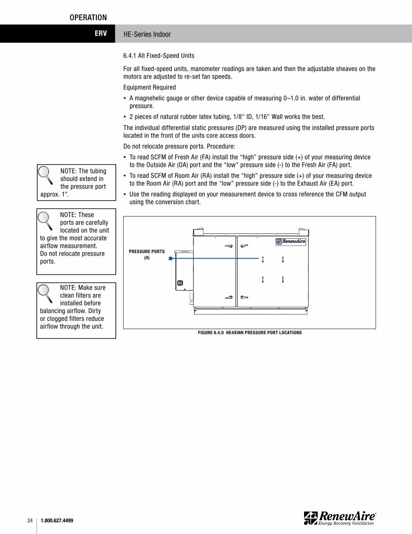
6.4.1 All Fixed-Speed Units
For all fixed-speed units, manometer readings are taken and then the adjustable sheaves on the motors are adjusted to re-set fan speeds.
Equipment Requiredu A magnehelic gauge or other device capable of measuring 0–1.0 in. water of differential
pressure.u 2 pieces of natural rubber latex tubing, 1/8" ID, 1/16" Wall works the best.
The individual differential static pressures (DP) are measured using the installed pressure ports located in the front of the units core access doors.
Do not relocate pressure ports. Procedure: u To read SCFM of Fresh Air (FA) install the “high” pressure side (+) of your measuring device
to the Outside Air (OA) port and the “low” pressure side (-) to the Fresh Air (FA) port.u To read SCFM of Room Air (RA) install the “high” pressure side (+) of your measuring device
to the Room Air (RA) port and the “low” pressure side (-) to the Exhaust Air (EA) port.u Use the reading displayed on your measurement device to cross reference the CFM output
using the conversion chart.
www.renewaire.com (800) 627- 4499 [email protected]
FIGURE 6.4.0 HE4XINH PRESSURE PORT LOCATIONS
PRESSURE PORTS (4)
NOTE: The tubing should extend in the pressure port
approx. 1".
NOTE: Make sure clean filters are installed before
balancing airflow. Dirty or clogged filters reduce airflow through the unit.
NOTE: These ports are carefully located on the unit
to give the most accurate airflow measurement. Do not relocate pressure ports.
251.800.627.4499
HE-Series Indoor ERV
OPERATION
DIFFERENTIAL STATIC ACROSS CORE DSP VS. CFM
HE4X
INH DP (H2O) DSP 0.20 0.30 0.40 0.50 0.60 0.70 0.80
Fresh Air (FA) CFM 1070 1600 2130 2670 3200 3740 4270
Room Air (RA) CFM 1140 1710 2280 2850 3420 3990 4560
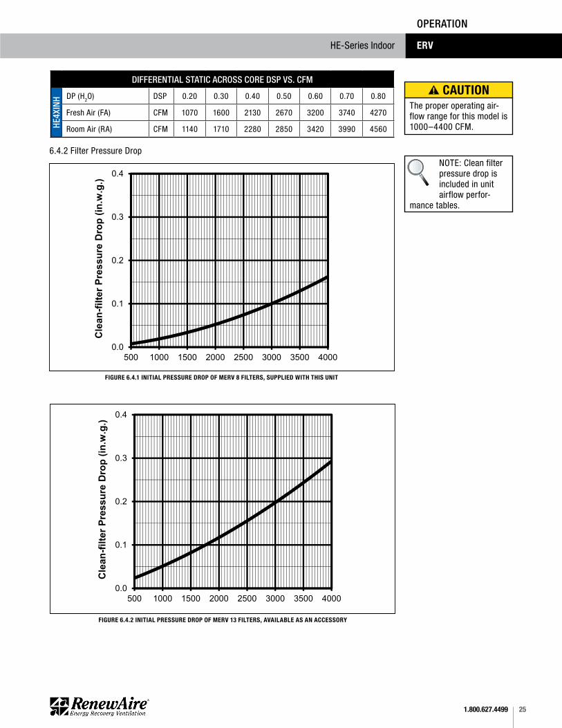
6.4.2 Filter Pressure Drop
FIGURE 6.4.1 INITIAL PRESSURE DROP OF MERV 8 FILTERS, SUPPLIED WITH THIS UNIT
Pleated_Filter_PD_APR16 (4)20x20x2 MERV 13 (IOM)
0.0
0.1
0.2
0.3
0.4
500 1000 1500 2000 2500 3000 3500 4000
Cle
an-fi
lter P
ress
ure
Dro
p (in
.w.g
.)
Unit Airflow (CFM)
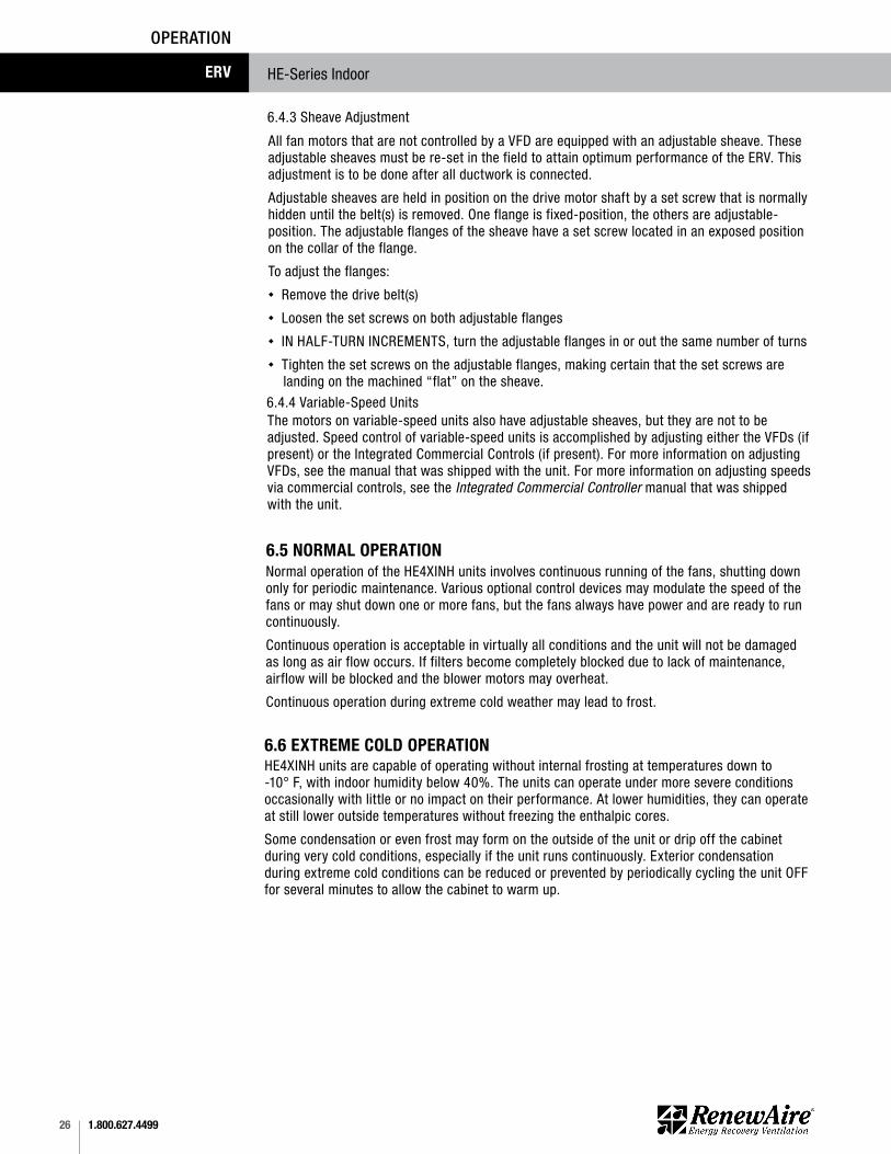
Initial Pressure Drop of MERV 13 Filters (available option)
FIGURE 6.4.2 INITIAL PRESSURE DROP OF MERV 13 FILTERS, AVAILABLE AS AN ACCESSORY
Pleated_Filter_PD_APR16 (4)20x20x2 MERV 8 (IOM)
0.0
0.1
0.2
0.3
0.4
500 1000 1500 2000 2500 3000 3500 4000
Cle
an-fi
lter P
ress
ure
Dro
p (in
.w.g
.)
Unit Airflow (CFM)
Initial Pressure Drop of MERV 8 Filters supplied with this unit NOTE: Clean filter
pressure drop is included in unit airflow perfor-
mance tables.
The proper operating air-flow range for this model is 1000–4400 CFM.
CAUTION
1.800.627.449926
HE-Series IndoorERV
OPERATION
6.5 NORMAL OPERATIONNormal operation of the HE4XINH units involves continuous running of the fans, shutting down only for periodic maintenance. Various optional control devices may modulate the speed of the fans or may shut down one or more fans, but the fans always have power and are ready to run continuously.
Continuous operation is acceptable in virtually all conditions and the unit will not be damaged as long as air flow occurs. If filters become completely blocked due to lack of maintenance, airflow will be blocked and the blower motors may overheat.
Continuous operation during extreme cold weather may lead to frost.
6.4.4 Variable-Speed UnitsThe motors on variable-speed units also have adjustable sheaves, but they are not to be adjusted. Speed control of variable-speed units is accomplished by adjusting either the VFDs (if present) or the Integrated Commercial Controls (if present). For more information on adjusting VFDs, see the manual that was shipped with the unit. For more information on adjusting speeds via commercial controls, see the Integrated Commercial Controller manual that was shipped with the unit.
6.4.3 Sheave Adjustment
All fan motors that are not controlled by a VFD are equipped with an adjustable sheave. These adjustable sheaves must be re-set in the field to attain optimum performance of the ERV. This adjustment is to be done after all ductwork is connected.
Adjustable sheaves are held in position on the drive motor shaft by a set screw that is normally hidden until the belt(s) is removed. One flange is fixed-position, the others are adjustable-position. The adjustable flanges of the sheave have a set screw located in an exposed position on the collar of the flange.
To adjust the flanges:u Remove the drive belt(s)u Loosen the set screws on both adjustable flangesu IN HALF-TURN INCREMENTS, turn the adjustable flanges in or out the same number of turnsu Tighten the set screws on the adjustable flanges, making certain that the set screws are landing on the machined “flat” on the sheave.
6.6 EXTREME COLD OPERATIONHE4XINH units are capable of operating without internal frosting at temperatures down to -10° F, with indoor humidity below 40%. The units can operate under more severe conditions occasionally with little or no impact on their performance. At lower humidities, they can operate at still lower outside temperatures without freezing the enthalpic cores.
Some condensation or even frost may form on the outside of the unit or drip off the cabinet during very cold conditions, especially if the unit runs continuously. Exterior condensation during extreme cold conditions can be reduced or prevented by periodically cycling the unit OFF for several minutes to allow the cabinet to warm up.

271.800.627.4499
HE-Series Indoor ERV
OPERATION
7.0 UNIT MAINTENANCE
7.1 MAINTENANCE 24 HRS. AFTER START-UP
RenewAire ERVs are built to operate with minimal maintenance. After unit commissioning, the primary areas of attention are the air filters, periodic lubrication of the fan motors and annual vacuuming of the enthalpic cores.
24 hours after unit start-up:u Readjust the tension on the motor drive belts.u In new installations, check the air filters since they will often collect dust, dirt and debris at the time of start-up.
7.2 MAINTENANCE 30 DAYS AFTER START-UPAfter 30 days of operation:u Tighten all electrical connections, paying special attention to VFD wiring (if present).u Readjust the tension on motor drive belts.u Check the air filters as part of the normal monthly maintenance.
7.3 MAINTENANCE SCHEDULEExperience on the part of the service person is the most important issue in establishing a maintenance schedule. There will be times of the year when frequent inspection of the filters will be required, such as spring and summer when there may be pollen, dust, dirt or debris from budding trees and bushes that can clog the filters. Also see Section 7.7 Maintenance Records in this manual.
7.4 FILTERSInspection and replacement of air filters is the most frequent maintenance issue. For units that do not have filter air pressure differential sensors, filters must be visually inspected monthly, as a minimum. If a filter looks discolored or dirty, REPLACE IT! When installing new filters, DO NOT USE filter sprays. Residue from the filter spray could migrate to the enthalpic core media and damage the cores.
For units that have filter air pressure differential sensors, a dirty filter alarm will occur on the connected alarm or control device.
Filter cleanliness and replacement is the most important and frequent maintenance issue. Dirty filters will cause an immediate reduction in operating efficiency of the ERV. Normally, filters should be inspected and changed when they are dirty. Paper filters are not to be cleaned, they are to be replaced. In general, if a filter looks dirty, replace it. The best indication of dirty filters is to check the pressure drop across the filter banks with an optional filter monitor. If it is not possible to check the pressure drop, the rule of thumb would be to change the filters every two months.
7.5 FAN MOTORSThe most important issues in motor maintenance are:u Belt condition and belt tensionu Sheave conditionu Motor cleanlinessu Motor lubrication 7.5.1 Belt TensionPremature or frequent belt failures can be caused by improper belt tension (either too loose or too tight) or misaligned sheaves. Abnormally high belt tension or drive misalignment will cause excessive bearing loads and may result in failure of the fan and/or motor bearings. Conversely, loose belts will cause squealing on start-up, excessive belt flutter, slippage and overheated sheaves. Both loose and tight belts can cause fan vibration.
Danger of injury if unit starts unexpectedly. Switch power off at service disconnect. Lock-out/tag-out the disconnect.
WARNING
Danger of Electrical Shock when servicing an installed unit.
ALWAYS DISCONNECT POWER SOURCE BEFORE SERVICING! More than one disconnect switch may be required.
Proper Wiring Size Selec-tion and Wiring Installation are the Responsibility of the Electrical Contractor.
WARNING
1.800.627.449928
HE-Series IndoorERV
MAINTENANCE
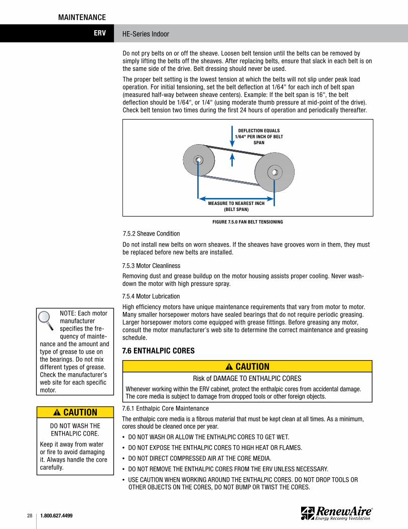
7.5.2 Sheave Condition
Do not pry belts on or off the sheave. Loosen belt tension until the belts can be removed by simply lifting the belts off the sheaves. After replacing belts, ensure that slack in each belt is on the same side of the drive. Belt dressing should never be used.
The proper belt setting is the lowest tension at which the belts will not slip under peak load operation. For initial tensioning, set the belt deflection at 1/64" for each inch of belt span (measured half-way between sheave centers). Example: If the belt span is 16", the belt deflection should be 1/64", or 1/4" (using moderate thumb pressure at mid-point of the drive). Check belt tension two times during the first 24 hours of operation and periodically thereafter.
Do not install new belts on worn sheaves. If the sheaves have grooves worn in them, they must be replaced before new belts are installed.
7.5.3 Motor Cleanliness
7.5.4 Motor Lubrication
Removing dust and grease buildup on the motor housing assists proper cooling. Never wash-down the motor with high pressure spray.
High efficiency motors have unique maintenance requirements that vary from motor to motor. Many smaller horsepower motors have sealed bearings that do not require periodic greasing. Larger horsepower motors come equipped with grease fittings. Before greasing any motor, consult the motor manufacturer’s web site to determine the correct maintenance and greasing schedule.
www.renewaire.com (800) 627- 4499 [email protected]
FIGURE 7.5.0 FAN BELT TENSIONING
DEFLECTION EQUALS 1/64" PER INCH OF BELT
SPAN
MEASURE TO NEAREST INCH (BELT SPAN)
7.6 ENTHALPIC CORES
7.6.1 Enthalpic Core Maintenance
The enthalpic core media is a fibrous material that must be kept clean at all times. As a minimum, cores should be cleaned once per year. u DO NOT WASH OR ALLOW THE ENTHALPIC CORES TO GET WET.u DO NOT EXPOSE THE ENTHALPIC CORES TO HIGH HEAT OR FLAMES.u DO NOT DIRECT COMPRESSED AIR AT THE CORE MEDIA.u DO NOT REMOVE THE ENTHALPIC CORES FROM THE ERV UNLESS NECESSARY.u USE CAUTION WHEN WORKING AROUND THE ENTHALPIC CORES. DO NOT DROP TOOLS OR OTHER OBJECTS ON THE CORES, DO NOT BUMP OR TWIST THE CORES.
Risk of DAMAGE TO ENTHALPIC CORES Whenever working within the ERV cabinet, protect the enthalpic cores from accidental damage. The core media is subject to damage from dropped tools or other foreign objects.
NOTE: Each motor manufacturer specifies the fre-quency of mainte-
nance and the amount and type of grease to use on the bearings. Do not mix different types of grease. Check the manufacturer’s web site for each specific motor.
CAUTION
DO NOT WASH THE ENTHALPIC CORE.
Keep it away from water or fire to avoid damaging it. Always handle the core carefully.
CAUTION

291.800.627.4499
HE-Series Indoor ERV
MAINTENANCE
7.6.2 Enthalpic Core Removal
Before removing enthalpic cores, switch the main disconnect to OFF. Open the door to the Energy Recovery Module and simply pull each core straight out of its guides.
7.6.3 Enthalpic Core ReplacementCores have foam gasketing on one end of each core. The core should be reinstalled so that the foam gasketing is toward the back of the ERV and the core label is facing toward the front.
To access enthalpic cores for cleaning, remove the air filters.
To clean enthalpic cores, all exposed surfaces must be vacuumed with an attachment having long, soft bristles. The greatest buildup of dirt and dust will normally be on the leading 1–2 inches of the inlet side (closest to the air filters).
When cores are removed from the ERV, they should be immediately
protected from accidental damage, water, high heat or flames.
1.800.627.449930
HE-Series IndoorERV
MAINTENANCE
7.7 MAINTENANCE RECORDS
MAINTENANCE LOG
ENTER DATES OF SERVICE
OA FILTER CHANGE
RA FILTER CHANGE
INSPECTION/ CLEANING
CLEAN CORE
CLEAN BLOWERS INITIALS
311.800.627.4499
HE-Series Indoor ERV
MAINTENANCE
7.8 HE4XINH SERVICE PARTS
www.renewaire.com (800) 627- 4499 [email protected] 7.8.0 HE4XINH SERVICE PARTS
8.0 TROUBLESHOOTINGIf problems occur with a RenewAire ERV, the primary resources for trouble-shooting are the unit as-built wiring schematics and the Sequence Of Operation (SOO) for each control scheme.
In the unlikely event that you need assistance from the factory for a specific issue, make sure that you have the information called for in the Unit Records page in the Owner Information section of this manual. The person you speak with at the factory will need that information to properly identify the unit and the installed options.
To contact RenewAire Customer Service:
Call 800-627-4499
Email: [email protected]
Remember that RenewAire Customer Service can only assist with the products sold by RenewAire, it cannot resolve engineering issues that result from air handling system design by others.
9.0 FACTORY ASSISTANCE
About RenewAireFor over 30 years, RenewAire has been a pioneer in enhancing indoor air quality (IAQ) in commercial and residential buildings of every size.This is achieved while maximizing sustainability through our fifth-generation, static-plate, enthalpic-core Energy Recovery Ventilators (ERVs) that optimize energy efficiency, lower capital costs via load reduction and decrease operational expenses by minimizing equipment needs, resulting in significant energy savings. Our ERVs are competitively priced, simple to install, easy to use and maintain and have a quick payback. They also enjoy the industry’s best warranty with the lowest claims due to long-term reliability derived from innovative design practices, expert workmanship and Quick Response Manufacturing (QRM).
As the pioneer of static-plate core technology in North America, RenewAire is the largest ERV producer in the USA. We’re committed to sustainable manufacturing and lessening our environmental footprint, and to that end our Waunakee, WI plant is 100% powered by wind turbines. The facility is also one of the few buildings worldwide to be LEED and Green Globes certified, as well as having achieved ENERGY STAR Building status. In 2010, RenewAire joined the Soler & Palau (S&P) Ventilation Group in order to provide direct access to the latest in energy-efficient air-moving technologies. For more information, visit: renewaire.com
Member of the S&P Group Family of Brands
2020 © RenewAire LLC134739_007_APR20