HE1XINH HE1XINV - RenewAire
32
HE1XINH HE1XINV HE SERIES ERV Installation, Operation and Maintenance Manual Model: HE1XINV shown Model: HE1XINH shown
Transcript of HE1XINH HE1XINV - RenewAire

HE1XINH HE1XINV
HE SERIES ERVInstallation, Operation and Maintenance Manual
Model: HE1XINV shownModel: HE1XINH shown
1.800.627.44992
HE-Series IndoorERV
Three phase motors are NOT suitable for use with solid state speed control.
Single phase EC motors are NOT suitable for use with solid state speed control. They already have speed control built into the motor electronics.
WARNINGMoteurs de trois phase ne convient pas pour utilisation avec regulateur de vitesse electronique.
Moteurs d’une phase de l’EC ne conviennent pas pour une utilisation avec regulateur de vitesse electronique. Ils ont déjà le contrôle de vitesse intégré dans le moteur électro-nique.
AVERTISSEMENT
RISK OF INJURY OR DAMAGE
Motor may have a manual reset thermal protector. Dis-connect power before servicing or resetting motor thermal protector. Use caution, motor may be hot. Allow the motor to cool before resetting the thermal protector.
If the motor thermal protector tripped, correct the issue that caused the motor to overheat (e.g. over motor rated amper-age or locked rotor).
If the motor has a manual reset thermal protector, the red thermal protector reset button is located on the motor body, on or near the lead end of the motor. If the button does not reset, the motor may still be too hot. Allow the motor to fully cool to reset the thermal protector, you should feel or hear a click when the thermal protector resets while pushing the reset button.
WARNINGARC FLASH AND ELECTRIC SHOCK HAZARD
Arc flash and electric shock hazard. Disconnect all electric power supplies, verify with a voltmeter that electric power is off and wear protective equipment per NFPA 70E before working within electric control enclosure. Failure to comply can cause serious injury or death.
Customer must provide earth ground to unit, per NEC, CEC and local codes, as applicable.
Before proceeding with installation, read all instructions, verifying that all the parts are included and check the nameplate to be sure the voltage matches available utility power.
The line side of the disconnect switch contains live high-voltage.
The only way to ensure that there is NO voltage inside the unit is to install and open a remote disconnect switch and verify that power is off with a volt meter. Refer to unit electrical schematic.Follow all local codes.
WARNING
RISK OF ELECTRIC SHOCK OR EQUIPMENT DAMAGE
Whenever electrical wiring is connected, disconnected or changed, the power supply to the ERV and its controls must be disconnected. Lock and tag the disconnect switch or circuit breaker to prevent accidental reconnection of electric power.
CAUTIONRISK OF CONTACT WITH HIGH SPEED MOVING PARTS
Disconnect all local and remote power supplies, verify with a voltmeter that electric power is off and all fan blades have stopped rotating before working on the unit.
Do not operate this unit with any cabinet panels removed.
CAUTION
This equipment is to be installed by following industry best practices and all applicable codes. Any damage to compo-nents, assemblies, subassemblies or the cabinet which is caused by improper installation practices will void the warranty.
IMPORTANT
This unit is for ventilating finished structures only. It is not to be used until after all construction has been completed and construction debris and dust are cleaned from the Occupied Space.
IMPORTANT
This unit is intended for general ventilating and heating only. Do not use to exhaust hazardous or explosive materials and vapors. Do not connect this equipment to range hoods, fume hoods or collection systems for toxics.
IMPORTANT

31.800.627.4499
HE-Series Indoor ERV
OWNER INFORMATION
SAVE THIS MANUAL
UNIT INFORMATIONRecord information as shown below.
In the unlikely event that factory assistance is ever required, information located on the unit label will be needed.
Locate the RenewAire unit label found on the outside of the unit.
NOTE: This information is for purposes of identifying the unit-specific option data from the Option Code.
UNIT INFORMATION
UNIT LABEL (TYPICAL)
H -X- IE -J1 N -
Option Code:
Serial Number:
SO #:
NOTE: This page is to be completed by the installing
contractor. The completed document is to be turned over to the owner after start-up.
This manual contains space for maintaining written records of unit maintenance and/or repairs. See Section 7.7 Maintenance Records. At the time the ERV is commissioned, a maintenance schedule should be developed by the user to incorporate monthly and seasonal maintenance and include start-up maintenance tasks as described in this manual.
NOTICE
1.800.627.44994
RENEWAIRE.COM 1.800.627.4499 14
SPECIFICATIONS & DIMENSIONS
Specifi cations may be subject to change without notice.
INDOOR UNIT SPECIFICATIONS
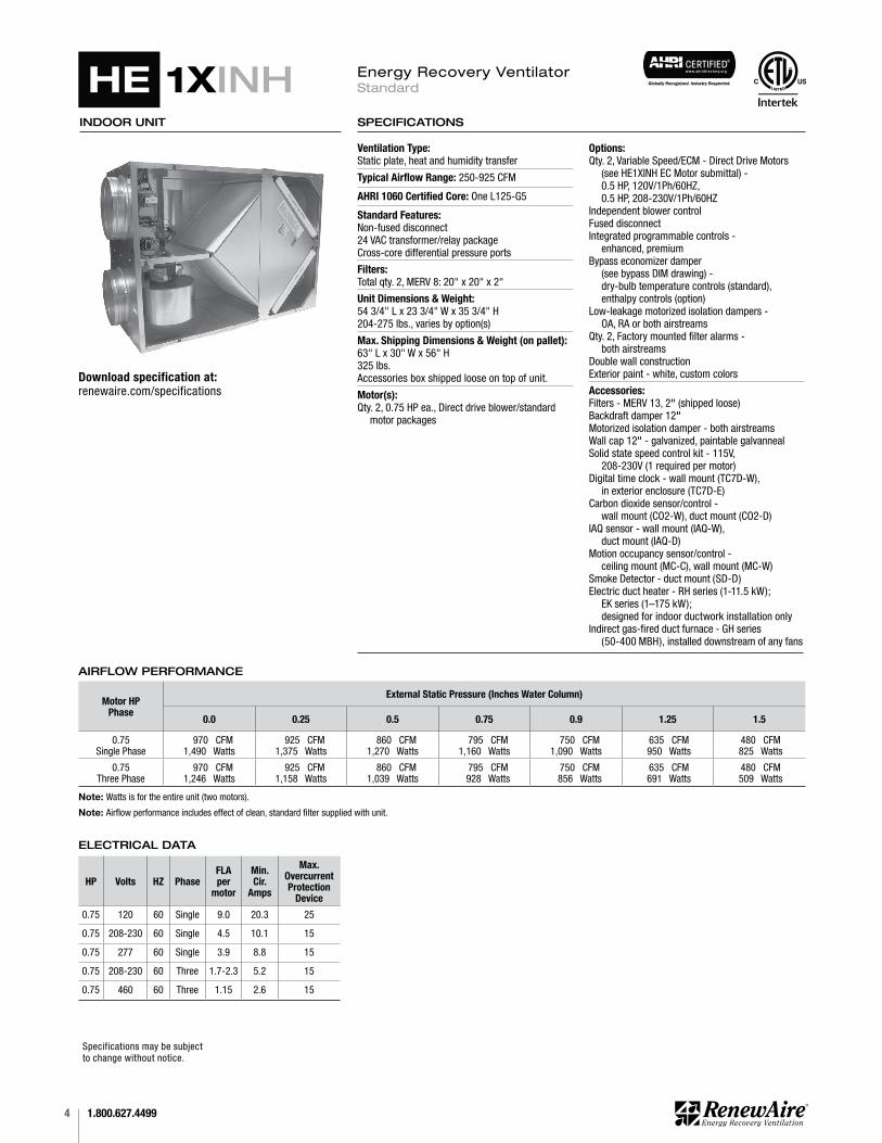
Ventilation Type: Static plate, heat and humidity transfer
Typical Airfl ow Range: 250-925 CFM
AHRI 1060 Certifi ed Core: One L125-G5
Standard Features:Non-fused disconnect24 VAC transformer/relay packageCross-core differential pressure ports
Filters: Total qty. 2, MERV 8: 20" x 20" x 2"
Unit Dimensions & Weight:54 3/4" L x 23 3/4" W x 35 3/4" H204-275 lbs., varies by option(s)
Max. Shipping Dimensions & Weight (on pallet): 63" L x 30" W x 56" H325 lbs. Accessories box shipped loose on top of unit.
Motor(s): Qty. 2, 0.75 HP ea., Direct drive blower/standard
motor packages
Options: Qty. 2, Variable Speed/ECM - Direct Drive Motors (see HE1XINH EC Motor submittal) -
0.5 HP, 120V/1Ph/60HZ, 0.5 HP, 208-230V/1Ph/60HZ
Independent blower controlFused disconnectIntegrated programmable controls - enhanced, premiumBypass economizer damper (see bypass DIM drawing) -
dry-bulb temperature controls (standard),enthalpy controls (option)
Low-leakage motorized isolation dampers - OA, RA or both airstreams
Qty. 2, Factory mounted fi lter alarms - both airstreamsDouble wall constructionExterior paint - white, custom colors
Accessories: Filters - MERV 13, 2" (shipped loose)Backdraft damper 12"Motorized isolation damper - both airstreamsWall cap 12" - galvanized, paintable galvanneal Solid state speed control kit - 115V,
208-230V (1 required per motor)Digital time clock - wall mount (TC7D-W),
in exterior enclosure (TC7D-E)Carbon dioxide sensor/control - wall mount (CO2-W), duct mount (CO2-D) IAQ sensor - wall mount (IAQ-W), duct mount (IAQ-D)Motion occupancy sensor/control - ceiling mount (MC-C), wall mount (MC-W)Smoke Detector - duct mount (SD-D) Electric duct heater - RH series (1-11.5 kW); EK series (1–175 kW); designed for indoor ductwork installation onlyIndirect gas-fi red duct furnace - GH series
(50-400 MBH), installed downstream of any fans
HP Volts HZ PhaseFLAper
motor
Min. Cir.
Amps
Max. Overcurrent Protection
Device
0.75 120 60 Single 9.0 20.3 25
0.75 208-230 60 Single 4.5 10.1 15
0.75 277 60 Single 3.9 8.8 15
0.75 208-230 60 Three 1.7-2.3 5.2 15
0.75 460 60 Three 1.15 2.6 15
ELECTRICAL DATA
AIRFLOW PERFORMANCE
Motor HPPhase
External Static Pressure (Inches Water Column)
0.0 0.25 0.5 0.75 0.9 1.25 1.5
0.75Single Phase
970 CFM1,490 Watts
925 CFM1,375 Watts
860 CFM1,270 Watts
795 CFM1,160 Watts
750 CFM1,090 Watts
635 CFM 950 Watts
480 CFM 825 Watts
0.75Three Phase
970 CFM1,246 Watts
925 CFM1,158 Watts
860 CFM1,039 Watts
795 CFM 928 Watts
750 CFM 856 Watts
635 CFM 691 Watts
480 CFM 509 Watts
Note: Airfl ow performance includes effect of clean, standard fi lter supplied with unit.
Note: Watts is for the entire unit (two motors).
1XINHHE
Download specification at:renewaire.com/specifications
Energy Recovery VentilatorStandard & Bypass Economizer OptionEnergy Recovery VentilatorStandard
Specifications may be subject to change without notice.

51.800.627.4499
FOR THE MOST COMPLETE AND CURRENT INFORMATION VISIT RENEWAIRE.COM 15
HE-S
ERIE
S
34
7/8"
Cas
e
3/4
"-1 7
/8" T
yp.
2 7
/8" T
yp.
49 1
/8"
Cas
e
RAOA
EA FA
Pres
sure
Ports
(4) T
yp.
Leve
ling
Feet
(4)
Doo
r-int
erlo
cked
Disc
onne
ct S
witc
h
35 5/8" Overall
27 1/2" 10
3/8"
10
3/8"
12"
Typ.
21
3/4"
Cas
e
54 3/4" Overall
20 1
/8" M
inim
umSe
rvic
e A
rea
(Doo
rs c
an b
eRe
mov
ed fr
om H
inge
s.)
49" MinimumService Area
(Doors can beRemoved from Hinges.)
29"
Alte
rnat
ePo
wer
Wiri
ngIn
let
7/8"
Alte
rnat
eC
ontro
l Wiri
ngIn
let
7/8"
23 3
/4"
Ove
rall
12"
Typ.
12
7/8"
8 5
/8"
27 5/8"
8 7/8" Typ.
Con
trol W
iring
Inle
t 7/
8"
Pow
er W
iring
Inle
t 7/
8"
OA
Isol
atio
nD
ampe
rW
iring
Con
n.
RA Is
olat
ion
Dam
per
Wiri
ng C
onn.
12"
TYP.
9" TYP.
6" TYP.
ISO
MET
RIC
VIE
W
LEFT
VIE
WFR
ON
T V
IEW
RI
GHT
VIE
W
TOP
VIE
W
Doo
rSw
ing
Doo
rSw
ing
(OA
/RA
) DA
MPE
R O
PTIO
N (Q
TY.2
)(S
HIPP
ED L
OO
SE)
SCA
LE 1
:16
FRO
NT
VIE
WRI
GHT
VIE
W
Mod
el: H
E1XI
NH
Dra
win
g Ty
pe: U
nit D
imen
sion
Ver
sion:
MA
Y18
ABB
REVI
ATIO
NS
EA: E
xhau
st A
ir to
Out
side
OA
: Out
side
Air
Inta
keRA
: Roo
m A
ir to
be
Exha
uste
dFA
: Fre
sh A
ir to
Insid
e
INST
ALL
ATIO
N O
RIEN
TATIO
NUn
it m
ay b
e in
stal
led
in a
ny
orie
ntat
ion.
NO
TE1.
UN
LESS
OTH
ERW
ISE
SPEC
IFIE
D,
DIM
ENSI
ON
S A
RE R
OUN
DED
TO
THE
N
EARE
ST E
IGHT
H O
F A
N IN
CH.
2. S
PEC
IFIC
ATIO
NS
MA
Y BE
SUB
JEC
T TO
CHA
NG
E W
ITHO
UT N
OTIC
E.
3.D
AM
PERS
SHI
PPED
LO
OSE
, FIE
LDIN
STA
LLA
TION
REQ
UIRE
D.
HE1X
INH
E
ne
rgy R
ec
ove
ry V
en
tila
tor
Sta
nd
ard
or
EC
Mo
tor
Op
tio
n
AIR
FLO
W C
ON
FIG
UR
ATIO
NAv
aila
ble
as s
how
n in
dim
ensi
on d
raw
ing.
UN
IT M
OU
NTIN
G &
AP
PLIC
ATIO
NCa
n be
mou
nted
in a
ny o
rient
atio
n. R
A/EA
airs
tream
ca
n be
sw
itche
d w
ith O
A/FA
airs
tream
unl
ess
certa
in o
ptio
ns a
re s
elec
ted.
HE1X
INH
E
ne
rgy R
ec
ove
ry V
en
tila
tor
Sta
nd
ard
Specifications may be subject to change without notice.

1.800.627.44996
RENEWAIRE.COM 1.800.627.4499 22
SPECIFICATIONS & DIMENSIONS
Specifi cations may be subject to change without notice.
INDOOR UNIT SPECIFICATIONS
Ventilation Type: Static plate, heat and humidity transfer
Typical Airfl ow Range: 250-925 CFM
AHRI 1060 Certifi ed Core: One L125-G5
Standard Features:Non-fused disconnect24 VAC transformer/relay packageCross-core differential pressure ports
Filters: Total qty. 2, MERV 8: 20" x 20" x 2"
Unit Dimensions & Weight:40 1/2" L x 23 3/4" W x 50 3/4" H201-272 lbs., varies by option(s)
Max. Shipping Dimensions & Weight (on pallet): 30" L x 42" W x 71" H325 lbs. Accessories box shipped loose on top of unit.
Motor(s): Qty. 2, 0.75 HP ea., Direct drive blower/standard
motor packages
Options: Qty. 2, Variable Speed/ECM - Direct Drive Motors (see HE1XINV EC Motor submittal) -
0.5 HP 120V/1Ph/60HZ,0.5 HP 208-230V/1Ph/60HZ
Independent blower control Fused disconnectIntegrated programmable controls - enhanced, premiumBypass economizer damper (see bypass DIM drawing) -
dry-bulb temperature controls (standard),enthalpy controls (option)
Low-leakage motorized isolation dampers - OA, RA or both airstreamsQty. 2, Factory mounted fi lter alarms - both airstreams Double wall constructionExterior paint - white, custom colors
Accessories: Filters - MERV 13, 2" (shipped loose)Backdraft damper 12" Motorized isolation damper - both airstreamsWall cap 12" - galvanized, paintable galvanneal Solid state speed control kit - 115V,
208-230V (1 required per motor)Digital time clock - wall mount (TC7D-W),
in exterior enclosure (TC7D-E)Carbon dioxide sensor/control - wall mount (CO2-W), duct mount (CO2-D) IAQ sensor - wall mount (IAQ-W), duct mount (IAQ-D)Motion occupancy sensor/control - ceiling mount (MC-C), wall mount (MC-W)Smoke Detector - duct mount (SD-D)Electric duct heater - RH series (1-11.5 kW); EK series (1–175 kW); designed for indoor ductwork installation onlyIndirect gas-fi red duct furnace - GH series
(50-400 MBH), installed downstream of any fans
HP Volts HZ PhaseFLAper
motor
Min. Cir.
Amps
Max. Overcurrent Protection
Device
0.75 120 60 Single 9.0 20.3 25
0.75 208-230 60 Single 4.5 10.1 15
0.75 277 60 Single 3.9 8.8 15
0.75 208-230 60 Three 1.7-2.3 5.2 15
0.75 460 60 Three 1.15 2.6 15
ELECTRICAL DATA
AIRFLOW PERFORMANCE
Motor HPPhase
External Static Pressure (Inches Water Column)
0.0 0.25 0.5 0.75 0.9 1.25 1.5
0.75Single Phase
970 CFM1,490 Watts
925 CFM1,375 Watts
860 CFM1,270 Watts
795 CFM1,160 Watts
750 CFM1,090 Watts
635 CFM 950 Watts
480 CFM 825 Watts
0.75Three Phase
970 CFM1,246 Watts
925 CFM1,158 Watts
860 CFM1,039 Watts
795 CFM 928 Watts
750 CFM 856 Watts
635 CFM 691 Watts
480 CFM 509 Watts
Note: Watts is for the entire unit (2 motors).Note: Airfl ow performance includes effect of clean, standard fi lter supplied with unit.
1XINVHE
Download specification at:renewaire.com/specifications
Energy Recovery VentilatorStandard & Bypass Economizer OptionEnergy Recovery VentilatorStandard
Specifications may be subject to change without notice.

71.800.627.4499
FOR THE MOST COMPLETE AND CURRENT INFORMATION VISIT RENEWAIRE.COM 23
HE-S
ERIE
S
49 1/8" Case 3
4 7/
8" C
ase
2
7/8
" Typ
.
17 3/4"
3/4
" - 1
7/8
" Typ
.
Pres
sure
Ports
(4) T
yp.
Doo
r-Int
erlo
cked
Disc
onne
ct S
witc
h
FRO
NT
VIE
W
Leve
ling
Feet
(4)
21 3
/4"
Cas
e
8 5
/8"
20 1
/8" M
inim
umSe
rvic
e A
rea
(Doo
rs c
an b
eRe
mov
ed fr
omHi
nges
.)
49" MinimumService Area(Doors can beRemoved from Hinges.)
29"
RIG
HT V
IEW
EA
OA
Isol
atio
nD
ampe
rW
iring
Con
n.
12
" Typ
. 1
0 3/
8" T
yp.
50 3/4" Overall 16 1/4"
Typ.
12
7/8"
40 3/4" Typ.
49 7/8" Typ.
Pow
er a
ndC
ontro
l Wiri
ngIn
lets
7/
8" LEFT
VIE
W
FA
RARA
Isol
atio
n D
ampe
rW
iring
Con
n.
23 3
/4"
Ove
rall
40 3/8" Overall
TOP
VIE
W
12"
TYP.
9" TYP.
6" TYP.
ISO
MET
RIC
VIE
W
Doo
rSw
ing
Doo
rSw
ing
OA
FRO
NT
VIE
WRI
GHT
VIE
W(O
A/R
A) D
AM
PER
OPT
ION
(QTY
. 2)
(SHI
PPED
LO
OSE
)SC
ALE
1:1
6
Mod
el: H
E1XI
NV
Dra
win
g Ty
pe: U
nit D
imen
sion
Ver
sion:
MA
Y18
ABB
REVI
ATIO
NS
EA: E
xhau
st A
ir to
Out
side
OA
: Out
side
Air
Inta
keRA
: Roo
m A
ir to
be
Exha
uste
dFA
: Fre
sh A
ir to
Insid
e
INST
ALL
ATIO
N O
RIEN
TATIO
NUn
it m
ay b
e in
stal
led
in a
ny
orie
ntat
ion.
NO
TE1.
UN
LESS
OTH
ERW
ISE
SPEC
IFIE
D,
DIM
ENSI
ON
S A
RE R
OUN
DED
TO
THE
N
EARE
ST E
IGHT
H O
F A
N IN
CH.
2. S
PEC
IFIC
ATIO
NS
MA
Y BE
SUB
JEC
T TO
CHA
NG
E W
ITHO
UT N
OTIC
E.
3. D
AM
PERS
SHI
PPED
LO
OSE
, FIE
LD
INST
ALL
ATIO
N R
EQUI
RED
AIR
FLO
W C
ON
FIG
UR
ATIO
NAv
aila
ble
as s
how
n in
dim
ensi
on d
raw
ing.
UN
IT M
OU
NTIN
G &
AP
PLIC
ATIO
NCa
n be
mou
nted
in a
ny o
rient
atio
n. R
A/EA
airs
tream
ca
n be
sw
itche
d w
ith O
A/FA
airs
tream
unl
ess
certa
in o
ptio
ns a
re s
elec
ted.
HE1X
INV
E
ne
rgy R
ec
ove
ry V
en
tila
tor
Sta
nd
ard
or
EC
Mo
tor
Op
tio
nHE1X
INV
E
ne
rgy R
ec
ove
ry V
en
tila
tor
Sta
nd
ard
Specifications may be subject to change without notice.

1.800.627.44998
HE-Series IndoorERV
5.5 WIRING SCHEMATICS............................................20
5.6 EXTERNAL CONTROL CONNECTIONS .....................225.6.1 Single 2-Wire Control, Unpowered .....................................225.6.2 Control Sending 24 VAC “On” Signal .................................225.6.3 Control Operating on Unit’s 24 VAC Power Supply ..............225.6.4 Control System with two Non-Powered Relay Contacts ......235.6.5 Control System Sending two 24 VAC “On” Signals (from an external power source) ................................................235.6.6 Control System Operating Isolation Dampers with End Switches .....................................................................23
5.7 QUICK START FOR TESTING CORRECT 3PH WIRING 23
6.0 OPERATION 24
6.1 PRINCIPLE OF OPERATION ....................................24
6.2 PRE-START-UP .....................................................246.2.1 Verify Voltages .................................................................. 246.2.2 Verify Transformer Wiring ................................................. 246.2.3 Inspect Filters .................................................................. 246.2.4 Inspect Foam Gasketing .................................................... 246.2.5 Inspect Fans ..................................................................... 246.2.6 Inspect and Clean the Cabinet Interior ............................... 246.2.7 Inspect Ductwork Connections .......................................... 24
6.3 UNIT START-UP ....................................................246.3.1 Fixed-Speed Units ............................................................. 24
6.4 BALANCING AIRFLOW ...........................................256.4.1 Filter Pressure Drop ..........................................................26
6.5 NORMAL OPERATION ............................................26
6.6 EXTREME COLD OPERATION .................................27
7.0 MAINTENANCE 27
7.1 MAINTENANCE 24 HRS. AFTER START-UP .............27
7.2 MAINTENANCE 30 DAYS AFTER START-UP .............27
7.3 MAINTENANCE SCHEDULE ....................................27
7.4 FILTERS ...............................................................27
7.5 FAN MOTORS .......................................................27
7.6 ENTHALPIC CORE .................................................287.6.1 Enthalpic Core Maintenance ..............................................287.6.2 Enthalpic Core Removal ....................................................287.6.3 Enthalpic Core Rempacement ............................................28
7.7 MAINTENANCE RECORDS .....................................29
7.8 SERVICE PARTS ....................................................30
8.0 TROUBLESHOOTING 31
9.0 FACTORY ASSISTANCE 31
TABLE OF CONTENTS
1.0 OVERVIEW 12
1.1 DESCRIPTION .......................................................12
1.2 AIRFLOW ..............................................................12
2.0 COMPONENT DESCRIPTIONS 12
2.1 CABINET ..............................................................12
2.2 ENTHALPIC CORES ...............................................13
2.3 FAN/MOTOR ASSEMBLIES .....................................13
2.4 E-BOX ..................................................................13
2.5 FILTERS ...............................................................13
2.6 FACTORY INSTALLED OPTIONS ..............................13
3.0 SHIPPING/RECEIVING/HANDLING 14
3.1 UNIT WEIGHTS AND DIMENSIONS .........................143.1.1 Unit Dimensions and Weight .............................................. 143.1.2 Maximum Shipping Dimensions and Weight ....................... 14
3.2 RIGGING AND CENTER OF GRAVITY .......................143.2.1 HE1XIN Hoisting Weights and COG ..................................... 14
3.3 RECIEVING ...........................................................15
3.4 STORAGE .............................................................15
4.0 UNIT PLACEMENT 16
4.1 BEFORE YOU BEGIN ..............................................16
4.2 SERVICE CLEARANCES .........................................16
4.3 SOUND ATTENUATION ...........................................164.3.1 Outside the Building .......................................................... 164.3.2 Ducts ............................................................................... 164.3.3 Radiated Noise ................................................................. 174.3.4 Aerodynamic (Velocity) Noise ............................................ 17
5.0 INSTALLATION 17
5.1 DUCTWORK ..........................................................175.1.1 Ducts to the Outside .......................................................... 175.1.2 Inside Ductwork System .................................................... 17
5.2 FLOOR INSTALLATION ...........................................17
5.3 SUSPENDED MOUNT ............................................18
5.4 ELECTRICAL REQUIREMENTS ................................185.4.1 Electronically Commutated Motors .................................... 185.4.2 Low Voltage Control System ............................................. 185.4.3 How to Reset the 24 VAC Circuit Breaker ........................... 195.4.4 Limits of Power Output ..................................................... 19
91.800.627.4499
HE-Series Indoor ERV
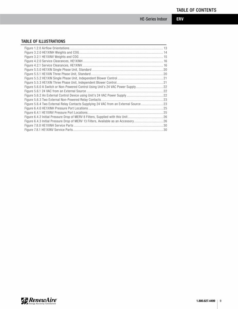
Figure 1.2.0 Airflow Orientations ....................................................................................................... 13Figure 3.2.0 HE1XINH Weights and COG ............................................................................................ 14Figure 3.2.1 HE1XINV Weights and COG ............................................................................................ 15Figure 4.2.0 Service Clearances, HE1XINH ........................................................................................ 16Figure 4.2.1 Service Clearances, HE1XINV ......................................................................................... 16Figure 5.5.0 HE1XIN Single Phase Unit, Standard .............................................................................. 20Figure 5.5.1 HE1XIN Three Phase Unit, Standard ............................................................................... 20Figure 5.5.2 HE1XIN Single Phase Unit, Independent Blower Control .................................................. 21Figure 5.5.3 HE1XIN Three Phase Unit, Independent Blower Control ................................................... 21Figure 5.6.0 A Switch or Non-Powered Control Using Unit’s 24 VAC Power Supply .............................. 22Figure 5.6.1 24 VAC from an External Source .................................................................................... 22Figure 5.6.2 An External Control Device using Unit’s 24 VAC Power Supply ........................................ 22Figure 5.6.3 Two External Non-Powered Relay Contacts .................................................................... 23Figure 5.6.4 Two External Relay Contacts Supplying 24 VAC from an External Source ........................ 23Figure 6.4.0 HE1XINH Pressure Port Locations .................................................................................. 25Figure 6.4.1 HE1XINV Pressure Port Locations ................................................................................... 25Figure 6.4.2 Initial Pressure Drop of MERV 8 Filters, Supplied with this Unit ....................................... 26Figure 6.4.3 Initial Pressure Drop of MERV 13 Filters, Available as an Accessory ................................ 26Figure 7.8.0 HE1XINH Service Parts .................................................................................................. 30Figure 7.8.1 HE1XINV Service Parts ................................................................................................... 30
TABLE OF CONTENTS
TABLE OF ILLUSTRATIONS

1.800.627.449910
HE-Series IndoorERV
MODEL NUMBER
"V", "H"
1 2 3 4 5 6 7 8 9 10 11 12 13 14 15 16 17 18 19 20 21 22 23 24 25
J - - -DIGIT NUMBER
Orientation Digit 9:
Wall Type Digit 11:
"S" = Single"D" = Double
Phase Digit 12:
"1" = Single Phase"3" = Three Phase
Digit 13:"1" = 115V"4" = 460V"5" = 208-230V"9" = 277V
Digit 14:
"H" = 0.75 HP Standard Direct-Drive Motors "E" = EC Direct Drive Motors
Digit 15:
"H" = 0.75 HP Standard Direct-Drive Motors "E" = EC Direct Drive Motors
Flow Control* Digit 18:
"-" = No Isolation Dampers (with no Bypass)"D" = Motorized Damper both Airstreams (with no Bypass)"E" = Motorized Damper EA or RA Airstream (with no Bypass)"F" = Motorized Damper FA or OA Airstream (with no Bypass)"0" = Drybulb Bypass Dampers only (no Isolation Dampers)"1" = Drybulb Bypass with Motorized Dampers all Airstreams"4" = Drybulb Bypass with Motorized Damper OA Airstream"5" = Enthalpy Bypass Dampers only (no Isolation Dampers)"6' = Enthalpy Bypass with Motorized Dampers all Airstreams"9" = Enthalpy Bypass witih Motorized Damper OA Airstream
*NOTES: Digit 6 "J" = G5 Core Type Digits 10, 16 and 17 are not used in these models.*Digit 18: Flow Control: Codes for Bypass: Face damper also acts as Isolation damper in EA or RA Airstream.
Restrictions:1: Voltage Codes "1" & "9" only available with Phase Code "1" (Single-Phase).2: Voltage Codes "4" & "8" only available with Phase Code "3" (Three-Phase).3: Motor Codes "EE" (EC Motors) only available with Phase Code "1" (Single Phase)4: Unit Control Code "G" (Terminal Strip) only available with Motor Codes "EE" (EC Motors). 5: Some units with Customization Code "X" are not safety listed. 6: Unit Control "A" not available with Unit Control Enhancements Codes "1", "2", "3" & "4".7: Voltage Code "9" not available with FA/EA Horsepower Codes "EE".
Digit 19:
"A" = Standard Unit Control Wiring"D" = Independent Blower Control "G" = Terminal Strip for EC Motors
Disconnect Digit 20:
"N" = Non-Fused (STANDARD)"F" = Fused
Digit 21:
"T" = Transformer with Isolation Relay (STANDARD)"1" = Enhanced Controls"2" = Premium Controls"3" = Enhanced Controls with BACNET License"4" = Premium Controls with BACNET License
Filter Options Digit 22:"-" = None"F" = Filter Monitor Both Airstreams
Other Options Digit 23:
"-" = None (Reserved)
Paint and Customization Digit 24:"-" = None"W" = White Paint"C" = Custom Paint"X" = Custom Unit
Digit 25:"L" = Listed"N" = Non-Listed
-X1-EH I N
Voltage (see Restriction 1 & 2)
FA Horsepower (see Restriction 3 & 7)
EA Horsepower (see Restriction 3 & 7)
Unit Control (see Restriction 4)
Safety Listing (see Restriction 5)
Unit Control Enhancements (see Restriction 6)
HE1XIN MODELPRODUCT CODE CHART
CONFIGURATION CODE
CONFIGURATION CODE
111.800.627.4499
HE-Series Indoor ERV
THIS PAGE IS INTENTIONALLY LEFT BLANK.
THIS PAGE IS INTENTIONALLY LEFT BLANK

1.800.627.449912
HE-Series IndoorERV
1.0 OVERVIEW
OVERVIEW
1.1 DESCRIPTIONThe HE1XIN Energy Recovery Ventilator is a device for recovering both sensible energy (heat) and latent energy (moisture) from the Exhaust Air from an Occupied Space and injecting those energies into an incoming Outside Air stream. It accomplishes this task by forcing the two airstreams through enthalpic cores, where the energy exchange takes place. The two airstreams pass through the enthalpic cores at right angles and the airstreams never mix together. See Section 2.2 Enthalpic Cores in this manual.
Each ERV has two electric blowers, one for each airstream. Fan speeds can be either single speed, or they can have electronically commutated motors. There are a number of different control devices available to control the operation or speed of the unit fans. For further information on available control accessories, see the HE RenewAire catalog.
There are two types of HE1X units, one for indoor installations and one for rooftop, or outdoor, installation. This manual is for the HE1XIN, which is the indoor unit. For information on the outdoor version of this product, see the HE1XRT Installation and Operation Manual.
These ERVs are commonly installed as part of an air handling system that provides heating and cooling of Supply Air. They can also be installed to operate as stand-alone devices when ducted directly to and from the Occupied Space.
Each HE1XIN unit is available in either a horizontal or a vertical model. The difference between the two models is in the airflow/ducting configuration. Horizontally ducted units are identified by the model name HE1XINH and vertically ducted units are identified as model HE1XINV.
Each unit has an integral 24 VAC power supply that is used internally and can also be used as a power source for other optional control devices.
The HE1XIN units are low-maintenance, requiring periodic replacement of the air filters, and annual vacuuming of the enthalpic cores. See Section 7.0 Unit Maintenance in this manual.
1.2 AIRFLOW
IMPORTANTIt is important to understand and use the equipment airstream terminology as it is used in this manual. The airstreams are defined as:u OUTSIDE AIR (OA): Air taken from the external atmosphere and, therefore, not previously
circulated through the system. u FRESH AIR (FA): Air that is downstream of the enthalpic cores and is ready for conditioning or
for return to the Occupied Space. u RETURN AIR (RA): Air that is returned to the ERV from a conditioned space. u EXHAUST AIR (EA): Air that is removed from a heating or cooling appliance or from the Occu-
pied Space and discharged.
There are two different airflow options for the HE1XIN. They are:u HE1XINHu HE1XINV
The airflow configuration is indicated by digit 9 of the Configuration Code.
NOTE: This unit is an Energy Recovery Ventilator, or ERV.
It is commonly referred to throughout this manual as an ERV.
131.800.627.4499
HE-Series Indoor ERV
COMPONENT DESCRIPTIONS
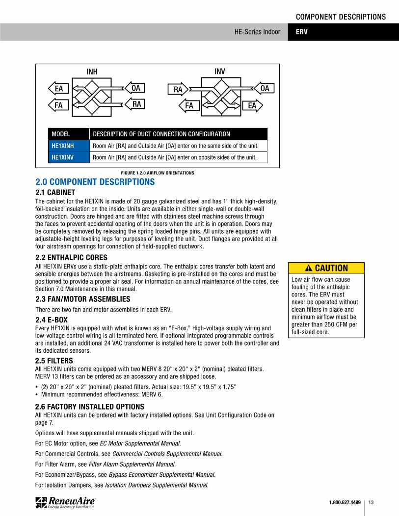
MODEL DESCRIPTION OF DUCT CONNECTION CONFIGURATION
HE1XINH Room Air [RA] and Outside Air [OA] enter on the same side of the unit.
HE1XINV Room Air [RA] and Outside Air [OA] enter on oposite sides of the unit.
FA
OA
RA
EA
HEIN except 6x 8x, LE_IN
INH
FA
OA
EA
RA
HEIN except 6x 8x, LEIN
INV
FIGURE 1.2.0 AIRFLOW ORIENTATIONS
2.0 COMPONENT DESCRIPTIONS2.1 CABINETThe cabinet for the HE1XIN is made of 20 gauge galvanized steel and has 1" thick high-density, foil-backed insulation on the inside. Units are available in either single-wall or double-wall construction. Doors are hinged and are fitted with stainless steel machine screws through the faces to prevent accidental opening of the doors when the unit is in operation. Doors may be completely removed by releasing the spring loaded hinge pins. All units are equipped with adjustable-height leveling legs for purposes of leveling the unit. Duct flanges are provided at all four airstream openings for connection of field-supplied ductwork.
2.2 ENTHALPIC CORESAll HE1XIN ERVs use a static-plate enthalpic core. The enthalpic cores transfer both latent and sensible energies between the airstreams. Gasketing is pre-installed on the cores and must be positioned to provide a proper air seal. For information on annual maintenance of the cores, see Section 7.0 Maintenance in this manual.
2.3 FAN/MOTOR ASSEMBLIES
2.4 E-BOXEvery HE1XIN is equipped with what is known as an “E-Box.” High-voltage supply wiring and low-voltage control wiring is all terminated here. If optional integrated programmable controls are installed, an additional 24 VAC transformer is installed here to power both the controller and its dedicated sensors.
2.5 FILTERSAll HE1XIN units come equipped with two MERV 8 20" x 20" x 2" (nominal) pleated filters. MERV 13 filters can be ordered as an accessory and are shipped loose.u (2) 20" x 20" x 2" (nominal) pleated filters. Actual size: 19.5" x 19.5" x 1.75" u Minimum recommended effectiveness: MERV 6.
2.6 FACTORY INSTALLED OPTIONSAll HE1XIN units can be ordered with factory installed options. See Unit Configuration Code on page 7.
Options will have supplemental manuals shipped with the unit.
For EC Motor option, see EC Motor Supplemental Manual.
For Commercial Controls, see Commercial Controls Supplemental Manual.
For Filter Alarm, see Filter Alarm Supplemental Manual.
For Economizer/Bypass, see Bypass Economizer Supplemental Manual.
For Isolation Dampers, see Isolation Dampers Supplemental Manual.
There are two fan and motor assemblies in each ERV.
Low air flow can cause fouling of the enthalpic cores. The ERV must never be operated without clean filters in place and minimum airflow must be greater than 250 CFM per full-sized core.
CAUTION

1.800.627.449914
HE-Series IndoorERV
3.0 SHIPPING/RECEIVING/HANDLINGHE1XIN units are palletized at the factory and then shipped by common carrier. Upon receipt by the installer, the shipment should be inspected for shipping damage, prior to unloading. Any discovered shipping damage should be immediately reported to the RenewAire sales rep and the damage must be recorded on the Bill Of Lading, prior to signing for acceptance of the shipment. The unit can be handled with a fork lift or a crane. Prior to moving the unit, verify that all latches and securing bolts on the cabinet doors are tightly fastened.
If a crane is used for moving the HE1XIN unit, unscrew the sheet metal plates that hold the adjustable legs to the pallet. Use two hoisting slings and a spreader bar to hoist the unit. The hoisting slings must be positioned around the ends of the unit so they do not touch the unit doors. Unit hoisting weights and Center of Gravity are detailed in Sections 3.1 and 3.2 in this manual.
Perform a test lift to make sure the unit is being hoisted level and is secure.
Place the HE1XIN unit on a flat surface where it will be protected from the weather and incidental damage. Do not remove protective coverings from any duct openings and keep the doors secured and tightly closed.
SHIPPING/RECEIVING
3.1 UNIT WEIGHTS AND DIMENSIONS3.1.1 Unit Dimensions and Weight:
HE1XINH: 54 3/4" L x 23 3/4" W x 35 5/8" H 204-275 lbs., varies by option(s)
HE1XINV: 40 3/8" L x 23 3/4" W x 50 3/4" H 201-272 lbs., varies by option(s) 3.1.2 Maximum Shipping Dimensions and Weight:
HE1XINH: 63" L x 30" W x 56" H 325 lbs.
HE1XINV: 30" L x 42" W x 71" H 325 lbs.
3.2 RIGGING AND CENTER OF GRAVITY3.2.1 HE1XIN Hoisting Weights and COG
There are pairs of rigging holes at each lower corner of the unit. Use slings or shackles at all four corners. Spreader bars are recommended in order to avoid damage to the unit.
HE1XINH Corner Weights
HE1XINH_CORNER_WEIGHTS_MAR20.dwg
Scale: 1" = 24"Do not scale drawing
RenewAire LLC
SPECIFICATIONS SUBJECT TO CHANGE WITHOUT NOTICE.
4/19/07 MF
JUN 18 MHK
BASIC UNIT WEIGHTS (lbs.)
Motors UNIT LF LR RR RF
.75 HP 1-PHASE 218 58 63 51 46
.75 HP 3-PHASE 229 61 66 56 48
ADDITIONAL WEIGHTS FOR OPTIONS (lbs.)
Options UNIT LF LR RR RF
Double Wall 65 15 15 19 16
By-Pass 1 0.5 0.5 0.0 0.0
RA or EA Damper 11 1 1 4.5 4.5
OA or FA Damper 11 2 3 2 3
Total Selected Weights
INDICATES LOCATIONS AT WHICH CORNER WEIGHTS ARE CALCULATED: LEGS.INDICATES LOCATIONS AT WHICH CORNER
WEIGHTS ARE CALCULATED: LEGS.
Center of gravity: From Left A = 18", From Front B = 12" (+/- 2")
47.95"
18.57"
LF RF
LR RR
UNIT COGRANGE
AB
MAR20 KMC
FIGURE 3.2.0 HE1XINH WEIGHTS AND COG
151.800.627.4499
HE-Series Indoor ERV
SHIPPING/RECEIVING
HE-1XINV Corner Weights
HE1XINV_CORNER_WEIGHTS_MAR20.dwg
Scale: 1" = 24"Do not scale drawing
RenewAire LLC
SPECIFICATIONS SUBJECT TO CHANGE WITHOUT NOTICE.
6/16/06 MF
33.88"
16.57"
JUN18 MHK
MAR20 KMC
LF RF
LR RR
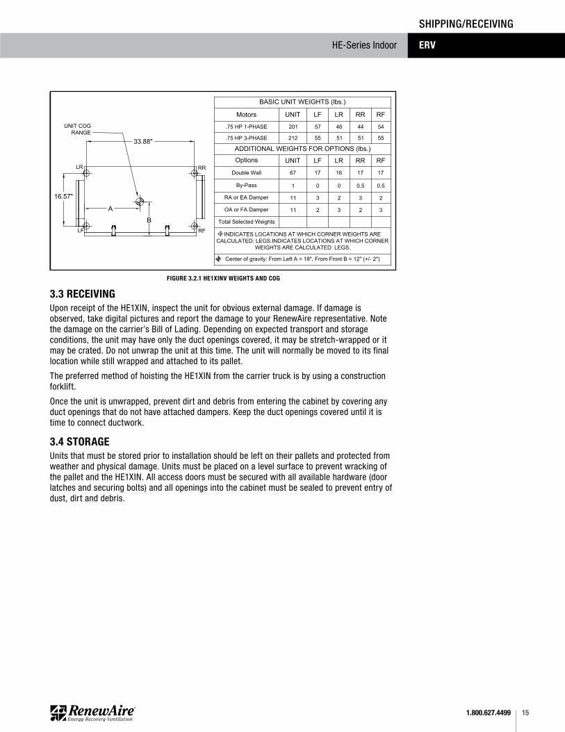
BASIC UNIT WEIGHTS (lbs.)
Motors UNIT LF LR RR RF
.75 HP 1-PHASE 201 57 46 44 54
.75 HP 3-PHASE 212 55 51 51 55
ADDITIONAL WEIGHTS FOR OPTIONS (lbs.)
Options UNIT LF LR RR RF
Double Wall 67 17 16 17 17
By-Pass 1 0 0 0.5 0.5
RA or EA Damper 11 3 2 3 2
OA or FA Damper 11 2 3 2 3
Total Selected Weights
INDICATES LOCATIONS AT WHICH CORNER WEIGHTS ARE CALCULATED: LEGS.INDICATES LOCATIONS AT WHICH CORNER
WEIGHTS ARE CALCULATED: LEGS.
Center of gravity: From Left A = 18", From Front B = 12" (+/- 2")
UNIT COGRANGE
AB
FIGURE 3.2.1 HE1XINV WEIGHTS AND COG
3.4 STORAGEUnits that must be stored prior to installation should be left on their pallets and protected from weather and physical damage. Units must be placed on a level surface to prevent wracking of the pallet and the HE1XIN. All access doors must be secured with all available hardware (door latches and securing bolts) and all openings into the cabinet must be sealed to prevent entry of dust, dirt and debris.
3.3 RECEIVINGUpon receipt of the HE1XIN, inspect the unit for obvious external damage. If damage is observed, take digital pictures and report the damage to your RenewAire representative. Note the damage on the carrier’s Bill of Lading. Depending on expected transport and storage conditions, the unit may have only the duct openings covered, it may be stretch-wrapped or it may be crated. Do not unwrap the unit at this time. The unit will normally be moved to its final location while still wrapped and attached to its pallet.
The preferred method of hoisting the HE1XIN from the carrier truck is by using a construction forklift.
Once the unit is unwrapped, prevent dirt and debris from entering the cabinet by covering any duct openings that do not have attached dampers. Keep the duct openings covered until it is time to connect ductwork.

1.800.627.449916
HE-Series IndoorERV
UNIT PLACEMENT
4.0 UNIT PLACEMENT4.1 BEFORE YOU BEGINThe HE1XIN is designed for installation in a sheltered location, out of the weather. The preferred mounting location is to place the unit on a concrete floor, although it can also be suspended from a ceiling or other structural support. See Section 5.3, Suspended Mount, in this manual.
For all installations, maintain needed service clearances as shown on the dimensioned drawings located in Section 4.2 of this manual. In addition, if the optional Bypass Economizer is ordered, additional clearance will be required for the extra bypass duct. See the RenewAire Supplemental Manual for ByPass or further information and clearance details specific to the HE1XIN units.
For all floor-mount installations, the unit should be set on its factory-provided adjustable legs and leveled. Select a location that is central to the inside duct runs and close to both the exhaust duct (to the outside) and also to the fresh air duct (from the outside).
The exhaust outlet and the outside air inlet on the outside of the building should be at least 10' apart to avoid cross-contamination. Comply with all local building codes in the positioning of the duct openings. Do not position the exhaust air outlet in a location where it will dump exhaust air into any enclosed or occupied space. The duct inlets and outlets should be screened against insects and vermin and should be shielded from the weather to prevent entry of rain or snow.
4.2 SERVICE CLEARANCES
FIGURE 4.2.0 SERVICE CLEARANCES, HE1XINH
34 7/8" Case
3/4"-1 7/8" Typ.
2 7/8" Typ.
49 1/8"Case
RA
OAEA
FA
PressurePorts (4) Typ.
LevelingFeet (4)
Door-interlockedDisconnect Switch
35
5/8"
Ove
rall
27
1/2"
10 3/8"
10 3/8"
12"Typ.
21 3/4" Case
54
3/4"
Ove
rall
20 1/8" MinimumService Area
(Doors can beRemoved from Hinges.)
49" M
inim
umSe
rvic
e A
rea
(Doo
rs c
an b
eRe
mov
ed fr
om H
inge
s.) 29"
AlternatePower WiringInlet 7/8"
AlternateControl WiringInlet 7/8"
23 3/4"Overall
12"Typ.
12 7/8"
8 5/8"
27
5/8"
8 7
/8" T
yp.
Control WiringInlet 7/8"
Power WiringInlet 7/8"
OA IsolationDamperWiring Conn.
RA IsolationDamperWiring Conn.
12"TYP. 9"
TYP.
6"TYP.
ISOMETRIC VIEW
LEFT VIEW FRONT VIEW RIGHT VIEW
TOP VIEW
DoorSwing
DoorSwing
(OA/RA) DAMPER OPTION (QTY.2)(SHIPPED LOOSE)
SCALE 1:16
FRONT VIEW RIGHT VIEW
Model: HE1XINHDrawing Type: Unit DimensionVersion: MAY18
ABBREVIATIONSEA: Exhaust Air to OutsideOA: Outside Air IntakeRA: Room Air to be ExhaustedFA: Fresh Air to Inside
INSTALLATION ORIENTATIONUnit may be installed in any orientation.
NOTE1. UNLESS OTHERWISE SPECIFIED,DIMENSIONS ARE ROUNDED TO THE NEAREST EIGHTH OF AN INCH.
2. SPECIFICATIONS MAY BE SUBJECT TO CHANGE WITHOUT NOTICE.
3.DAMPERS SHIPPED LOOSE, FIELDINSTALLATION REQUIRED.
49
1/8"
Cas
e
34 7/8" Case 2 7/8" Typ.
17
3/4"
3/4" - 1 7/8" Typ.
PressurePorts (4) Typ.
Door-InterlockedDisconnect Switch
FRONT VIEW
LevelingFeet (4)
21 3/4"Case
8 5/8"
20 1/8" MinimumService Area
(Doors can beRemoved from
Hinges.)49
" Min
imum
Serv
ice
Are
a(D
oors
can
be
Rem
oved
from
Hin
ges.)
29"
RIGHT VIEW
EA
OA IsolationDamperWiring Conn.
12" Typ. 10 3/8" Typ.
50
3/4"
Ove
rall
16 1
/4"
Typ.
12 7/8"
40
3/4"
Typ
.
49
7/8"
Typ
.
Power andControl Wiring
Inlets 7/8"
LEFT VIEW
FA
RARA Isolation DamperWiring Conn.
23 3/4"Overall
40
3/8"
Ove
rall
TOP VIEW
12"TYP.
9"TYP.
6"TYP.
ISOMETRIC VIEW
DoorSwing
DoorSwing
OA
FRONT VIEW RIGHT VIEW(OA/RA) DAMPER OPTION (QTY. 2)
(SHIPPED LOOSE)SCALE 1:16
Model: HE1XINVDrawing Type: Unit DimensionVersion: MAY18
ABBREVIATIONSEA: Exhaust Air to OutsideOA: Outside Air IntakeRA: Room Air to be ExhaustedFA: Fresh Air to Inside
INSTALLATION ORIENTATIONUnit may be installed in any orientation.
NOTE1. UNLESS OTHERWISE SPECIFIED,DIMENSIONS ARE ROUNDED TO THE NEAREST EIGHTH OF AN INCH.
2. SPECIFICATIONS MAY BE SUBJECT TO CHANGE WITHOUT NOTICE.
3. DAMPERS SHIPPED LOOSE, FIELD INSTALLATION REQUIRED
FIGURE 4.2.1 SERVICE CLEARANCES, HE1XINV
4.3 SOUND ATTENUATIONTake these simple steps to attenuate noise from the unit. 4.3.1 Outside the Building
Exhaust velocity noise is the primary cause of unit-related noise outside the building. Size the exhaust duct and grille for less than 1000 feet per minute (FPM) air velocity. When practical, orient the exhaust air hood to point away from houses or public areas. 4.3.2 Ducts
Make sure the ductwork at the unit outlets is stiff enough to resist the flexure and resulting booming associated with system start-up and shut-off, as well as the turbulent flow conditions at the blower outlets.

171.800.627.4499
HE-Series Indoor ERV
INSTALLATION
In general, provide smooth transitions from the ERV’s outlets to the duct. The ducts connecting to the outlets should be straight for a sufficient distance, with gradual transitions to the final duct size.
These guidelines are consistent with SMACNA recommended duct layout practices for efficient and quiet air movement. Follow SMACNA guidelines. 4.3.3 Radiated Noise
The HE1XIN is insulated with high-density fiberglass. This provides significant attenuation of radiated sound.
The outlet ducts can be significant sources of radiated sound as well. The FA and EA ducts (outlet ducts) should be insulated for sound control. This insulation should start at the unit. At a minimum the first 10' of duct should be insulated. All parts of the FA and EA ducts located in the mechanical space should be insulated for sound control, both to minimize sound radiation out of these ducts and also to control sound radiation into the ducts. 4.3.4 Aerodynamic (Velocity) Noise
When sound attenuation is a design concern, the primary consideration is velocity noise at the unit’s Fresh Air blower outlet.The average velocity at the blower outlets is 2482 FPM when the unit is operating at 750 CFM.
5.0 INSTALLATION5.1 DUCTWORK5.1.1 Ducts to the Outside
The exhaust outlet and fresh air inlet on the outside of the building should be at least 10' apart to avoid cross-contamination. The exhaust outlet should not dump air into an enclosed space or any other structure. The inlets and outlets should be screened against insects and vermin and shielded from the weather to prevent the entry of rain or snow.
Ducts connecting the HE1XIN to the outside must be insulated, with sealed vapor barrier on both inside and outside of the insulation. Insulate both the Outside Air (OA) and Exhaust Air (EA) ducts. 5.1.2 Inside Ductwork System
Ensure Good Ductwork Design Ductwork should be designed to allow the unit to provide the required airflow and reduce pressure drop for efficient, quiet operation. If the inside ducts run through unconditioned spaces they must be insulated with a sealed vapor barrier on both inside and outside of insulation.
Use Non-motorized Dampers to Set and Balance Air. In most applications, the airflow rate for both the Fresh Air and the Exhaust Air should be roughly equal (or “balanced”) for best performance of the HE1X Unit. See unit specification sheet for CFM/ESP curves.
5.2 FLOOR INSTALLATIONMost units are installed in a location specified by others. In general, it’s preferable to install the unit on a flat, reasonably level surface, such as a concrete floor. The factory-installed leveling legs are to be used to level the unit before connecting ductwork. When positioning the unit, it is not to be slid on its adjustable legs because they can be bent.
NOTE: Ducts inside a building that are connected to the outside must be
insulated with a sealed vapor barrier on both the inside and the outside of the insulation.
NOTE: To prevent the entry of rain through the outside
air inlet duct, observe the following: 1. Velocity at face of inlet
hood should not exceed 500 FPM.
2. Inlet duct must be at least 12" inside diameter.
3. Centerline length along duct from weather hood to unit inlet must be at least 48".
4. Inlet duct must pitch downward to the out-side; centerline of inlet hood must be at least 18" below the centerline of the unit inlet.
5. Outlet duct must pitch downward to the outside with a slope of at least ¼" to the foot.

1.800.627.449918
HE-Series IndoorERV
INSTALLATION
The HE1XIN weighs 210 lbs. It is the installer’s responsibility to make sure that the screws or bolts used for securing the units are properly selected for the loads and substrates involved.
CAUTION
NOTE: That leveling legs supplied with HE1XIN can be
removed and replaced with 3/8-16" bolts to secure unit to mounting brackets, if desired.
NOTE: Standard HE1XIN with single phase original
equipment motors are suitable for use with solid state speed control.
NOTE: Le HE1X-IN avec moteurs d’équipement
d’origine monophasés sont adaptés pour une utilisa-tion avec regulateur de vitesse electronique.
5.4 ELECTRICAL REQUIREMENTS5.4.1 Electronically Commutated Motors
These ERVs may be ordered with factory-installed features including Electronically Commutated (EC) Motors. Consult the EC Motor Supplemental Manual for more information.
Electrical Options are identified on the Unit Label located near electrical box on the outside of the unit. Find the complete Unit Model Number in the lower left corner of the Unit Label. Use the configuration chart to determine motor power and voltage installed in your HE1XIN.
Use conduit, strain reliefs, etc. as required by code to secure the field wiring. Electrical knockouts are provided for alternate line voltage and voltage control locations for field wiring to the internal electrical box. If the alternate sites are desired for field wiring then carefully remove the knockout plugs and foam insulating plugs from the alternate sites and install them in the open knockout locations. 5.4.2 Low Voltage Control System
This ERV is provided with a Class II 24 VAC power supply system that operates the unit’s contactor(s) for HE1XIN. The ERV’s 24 VAC Power Supply can also be used to power the externally-installed controls system: up to 8 VA of power is available.
The unit’s power supply system includes isolation relay(s) so you can use external controls whose contact ratings are as low as 50 mA (1.2 VA). Also, it is possible to operate the isolation relays with 24 VAC power from an external source (with proper wiring connections).
A built-in circuit-breaker prevents damage to the transformer and other low-voltage components in the event of a short-circuit or overload. In extreme cases, the transformer itself is designed to fail safely.
Specifications:u Nominal Output Voltage under load: 24 VACu Typical Output Voltage at no load: 29–31 Vu Minimum contact rating for connected control device: 50 mA (1.2 VA)u Circuit Breaker Trip Point: 3 A
Before bringing power to the unit check unit nameplate to confirm it matches the voltage and phase of the power you are supplying. Remember that your field connections need to be accessible for inspection.
CAUTION
5.3 SUSPENDED MOUNTHE1XIN units can also be suspended from a ceiling or other structural member. The preferred method of support is to remove the four adjustable legs and bolt heavy-gauge Unistrut or other structural channels to the underside of the unit, using the 3/8-16" threaded holes where the adjustable legs were located. Install 3/8-16" bolts through the channels, into the bottom of the unit. Support the channels from threaded rods, located in an appropriate location that maintains required service clearances

191.800.627.4499
HE-Series Indoor ERV
INSTALLATION
1. Connect only to components intended for use with 24 VAC power.
2. Do not undersize the low-voltage wires connected to this device. Observe the wire length and gauge limits indicated in this manual.
3. Do not overload this unit’s 24 VAC power supply system. Confirm that the power require-ments of devices you connect to this power supply system do not exceed 8 VA in total.
4. If an external source of 24 VAC power is used to control the unit, consult the wiring schematics and connect the external power only to the specified terminals in order to avoid damaging the unit or external controls. Connect only CLASS II power to the control terminals of this unit.
5. Unit is not equipped to receive analog signals (such as 1–10 vdc or 4–20 mA).
CAUTION
5.4.3 How to Reset the 24 VAC Circuit Breaker
If the transformer is subjected to an excessive load or a short circuit, the circuit breaker will trip to prevent the failure of the transformer. When it trips the circuit breaker’s button pops up. Shut off the primary-side power to the unit, and remove the excessive load or the short. The circuit breaker can be reset about fifteen seconds after it trips by pressing in the button. 5.4.4 Limits of Power Output
If limits on wire gauge and length are observed, you may connect control devices that draw up to 8 VA to the blue and red wires. More than one device can be connected as long as total steady-state load does not exceed 8 VA.
If primary-side voltage is 230 VAC, move black primary-side lead from transformer’s “208 V” terminal to the transform-er’s terminal marked “240 V” (“230 V” in some units). Do not move the black primary-side lead that is connected to the trans-former’s “COM” terminal.
NOTICE
Be careful if the external control system provides 24 VAC power at its control output: make sure blue and red leads are separately capped and not connected to any other wires.
CAUTION
Wire Gauge #22 #20 #18 #16 #14 #12
Circuit Length 100' 150' 250' 400' 700' 1000'
“Circuit Length” is distance from ERV to Control Device.
Observe these limits to wire length and gauge in order to ensure reliable operation of the control system.

1.800.627.449920
HE-Series IndoorERV
INSTALLATION
CHANGESNAMEREV. DATE
Description
Family
Config
No Dampers
RenewAire
1
A B C D E
New0 11/7/2017 austine
1 5/30/2018 austine Updated Wire Colors
2 8/10/2018 austine Added Wire Color Labels
3 3/14/2019 austine Updated Wire Damper Colors
4 9/4/2019 austine Updated Field Wire Colors
HE-1XJINx-x11,15,19xx--xAxTx-xx
2
3
4
5
6
7
8
9
10
11
12
13
HE-1XJINx-x11,15,19xx---AxTx-xx_004
Input Power115 VAC, 1 Phase208-230 VAC, 1 Phase277 VAC, 1 Phase
277 VAC
F1
Contactor
24 VAC
A1 A2
1L1
3L2
2T1
4T2
Transformer
COM 24V
Exhaust Fan
M
Supply Fan
Contactor
24 VAC
A1 A2
1L1
3L2
2T1
4T2
M
M1
208 VAC
115 VAC
Relay
24 VAC
13 14
812
4
RD BU
BK BK
BU
RD
RD
BK
BU OR
YE YE
RD
BU
FIGURE 5.5.0 HE1XIN SINGLE PHASE UNIT, STANDARD
FIGURE 5.5.1 HE1XIN THREE PHASE UNIT, STANDARD
5.5 WIRING SCHEMATICS
CHANGESNAMEREV. DATE
Description
Family
Config
No Dampers
RenewAire
1
A B C D E
New0 11/8/2017 austine
1 5/30/2018 austine Updated Wire Colors
2 8/14/2018 austine Added Wire Color Labels
3 3/14/2019 austine Updated Damper Wire Colors
4 9/4/2019 austine Updated Field Wiring Colors
HE-1XJINx-x34,35xx--xAxTx-xx
2
3
4
5
6
7
8
9
10
11
12
13
HE-1XJINx-x34,35xx---AxTx-xx_004
Input Power208-230 VAC, 3 Phase460 VAC, 3 Phase
F1
Contactor
24 VAC
A1 A2
1L1
3L2
5L3
2T1
4T2
6T3
Transformer
COM 24V
Exhaust Fan
M
Supply Fan
L1 L2 L3 GND
Relay
24 VAC
13 14
812
4
RD YLRD
YL
BU
BURD
YL
BU
BU OR
BK BK
RD
BU
YL
YL

211.800.627.4499
HE-Series Indoor ERV
INSTALLATION
CHANGESNAMEREV. DATE
Description
Family
Config
No Dampers
RenewAire
1
A B C D E
Updated Wire Colors1 5/30/2018 austine
2 8/10/2018 austine Added Wire Color Labels
3 3/14/2019 austine Updated Damper Wire Colors
4 5/15/2019 austine Updated Wago Placement
5 9/4/2019 austine Updated Field Wiring Colors
HE-1XJINx-x11,15,19xx--xDxTx-xx
2
3
4
5
6
7
8
9
10
11
12
13
HE-1XJINx-x11,15,19xx---DxTx-xx_005
M1
277 VAC
Contactor
24 VAC
A1 A2
1L1
3L2
2T1
4T2
M
Supply Fan
Exhaust Fan
Input Power115 VAC, 1 Phase208-230 VAC, 1 Phase277 VAC, 1 Phase
Transformer
COM 24V
Contactor
24 VAC
A1 A2
1L1
3L2
2T1
4T2
Exhaust
F1
Contactor
24 VAC
A1 A2
1L1
3L2
2T1
4T2
Supply
115 VAC
Relay
24 VAC
13 14
812
4
SupplyRelay
24 VAC
13 14
812
4
Exhaust
RD BURD
BU
BK BK
RD
BK
RD
BK
BU OR
OR
RD
BU
BU
YL
YL
FIGURE 5.5.2 HE1XIN SINGLE PHASE UNIT, INDEPENDENT BLOWER CONTROL
CHANGESNAMEREV. DATE
Description
Family
Config
No Dampers
RenewAire
1
A B C D E
Updated Wire Colors1 5/30/2018 austine
2 8/10/2018 austine Added Wire Color Labels
3 3/14/2019 austine Updated Damper Wire Colors
4 5/15/2019 austine Updated Wago Placement
5 9/4/2019 austine Updated Field Wiring Colors
HE-1XJINx-x34,35xx--xDxTx-xx
2
3
4
5
6
7
8
9
10
11
12
13
HE-1XJINx-x34,35xx---DxTx-xx_005
M
Supply Fan
Exhaust Fan
GNDL3L2L1
Input Power208-230 VAC, 3 Phase460 VAC, 3 Phase
Transformer
COM 24V
Contactor
24 VAC
A1 A2
1L1
3L2
5L3
2T1
4T2
6T3
Exhaust
F1
Contactor
24 VAC
A1 A2
1L1
3L2
5L3
2T1
4T2
6T3
Supply
Relay
24 VAC
13 14
812
4
SupplyRelay
24 VAC
13 14
812
4
Exhaust
RD YL BURD
YL
BU
RD
YL
BU
RD
YL
BU
RD
BU
OR
ORBU
BKBK
YL
YL
BU
FIGURE 5.5.3 HE1XIN THREE PHASE UNIT, INDEPENDENT BLOWER CONTROL

1.800.627.449922
HE-Series IndoorERV
5.6 EXTERNAL CONTROL CONNECTIONS5.6.1 Single 2-Wire Control, Unpowered
Use the schematic shown in Figure 5.6.0; if the control requires no power to operate and acts like a simple on/off switch. The control must not supply any power to the ERV unit. u Connect the blue lead to one yellow lead. u Connect the control’s contacts to the red lead and the remaining yellow lead.
Control on separate Power Supply, no power present at Control Output: u Wire as shown for the Single 2-wire control.
NOTE: The sim-plified schematics below show only
the relevant portions of the low-voltage control circuit in the ERV unit and representational external control approaches. See the complete unit schematics above.
Make sure the control pro-vides no voltage or current at its output terminals.
CAUTION
FIGURE 5.6.0 A SWITCH OR NON-POWERED CONTROL USING UNIT’S 24 VAC POWER SUPPLY
Unit 24VAC
Power Supply
Connect Blue & First Yellow Leads
Connect Switch between Red &
Second Yellow Leads
UNIT INTERNAL CONTROL WIRING
CIsolation
Relay Coil
(SIMPLIFIED)
A SWITCH OR NON-POWERED
CONTROL USING UNIT'S 24VAC POWER
SUPPLY
Image 1 from filename Control Connections EV450-HE1XIN_DEC14
KMC 12/11/14
BLUE
YEL
YEL
RED
Supply only 24 VAC (not VDC) from a Class II Power Source.
CAUTION
5.6.2 Control Sending 24 VAC “ON” Signal
Use the schematic shown in Figure 5.6.1 if a 24 VAC “ON” signal is to be sent from an external power source to the ERV.u Make sure the blue and red leads are separately capped and not connected to any other
wires.
Now you safely can apply 24 VAC to the two yellow leads to operate the ERV’s isolation relay.
FIGURE 5.6.1 24 VAC FROM AN EXTERNAL SOURCE
Unit 24VAC
Power Supply
Cap Blue and Red Leads when using
24VAC from external source.
C
UNIT INTERNAL CONTROL WIRING(SIMPLIFIED)
24VAC FROM AN EXTERNAL SOURCE
Isolation
Relay Coil
Image 3 from filename Control Connections EV450-HE1XIN_DEC14
KMC 12/11/14
RED
YEL
YEL
BLUE
External control system should not draw more than 8 VA.
CAUTION
5.6.3 Control Operating on Unit’s 24 VAC Power Supply
Use the schematic shown in Figure 5.6.2 if controls are operating on unit’s 24 VAC power supply.u 24 VAC power is available at the blue and red leads. u Connect one of the yellow leads to the blue lead. u Connect the switched output of the Control to the red lead to operate the ERV’s isolation
relay.
FIGURE 5.6.2 AN EXTERNAL CONTROL DEVICE USING UNIT’S 24 VAC POWER SUPPLY
Connect Blue & First Yellow Leads
Connect Control's N.O. Output to 2nd Yellow Lead
External Control is
powered by 24VAC
available between the Red
and Blue leads.
8VA Maximum Load.
Unit 24VAC
Power SupplyC
UNIT INTERNAL CONTROL WIRING(SIMPLIFIED)
AN EXTERNAL CONTROL DEVICE USING
UNIT'S 24VAC POWER SUPPLY
Isolation
Relay Coil
MP
U
Image 2 from filename Control Connections EV450-HE1XIN_DEC14
KMC 12/11/14
BLUE
YEL
YEL
RED
INSTALLATION

231.800.627.4499
HE-Series Indoor ERV
INSTALLATION
5.6.5 Control System Sending two 24 VAC “On” Signals (from an external power source)
Use Figure 5.6.4 only if the ERVs has Independent Blower Control: u Make sure the blue and red leads are separately capped and not connected to any other
wires.
Now you safely can apply one of the 24 VAC signals to the one of the yellow leads (marked “FA Blower” and “EA Blower”) and the blue lead to operate one of the ERV’s isolation relay. u Supply the second 24 VAC signal to the other yellow lead and again to the blue lead (make
sure the polarity of each wire connected to the blue lead is the same).
FIGURE 5.6.4 TWO EXTERNAL RELAY CONTACTS SUPPLYING 24 VAC FROM AN EXTERNAL SOURCE
RED
Isolation Relay Coils
(FA Blower)
(EA Blower)
BLUE
YEL
BLUE
UNIT INTERNAL WIRING
YEL
1st Blue Lead Capped
Unit 24VAC
Power Supply
C
C
TWO EXTERNAL RELAY CONTACTS
SUPPLYING 24VAC FROM AN
EXTERNAL SOURCE
Red Lead Capped
Image 5 from filename Control Connections EV450-HE1XIN_DEC14
KMC 12/11/14
Supply only 24 VAC (not VDC) from a Class II Power Source.
CAUTION
5.6.6 Control System Operating Isolation Dampers with End Switches
Use Isolation Dampers with electrically separate end switches. The end switches are used to separately control the ERV unit’s Isolation Relays. Also, specify the ERV with Independent Blower Control. This ensures that each damper is open before the respective blower starts up.
5.6.4 Control System with two Non-Powered Relay Contacts:
ERVs with Independent Blower Control Only:
Use Figure 5.6.3 if the external control system provides no voltage or current at its output contacts. u Connect the two blue leads together. u Connect the red lead to one side of each of the output contacts. u Connect the other side of the output contacts to the appropriate yellow leads (marked “FA
Blower” and “EA Blower”).
FIGURE 5.6.3 TWO EXTERNAL NON-POWERED RELAY CONTACTS
RED
Isolation Relay Coils
(FA Blower)
(EA Blower)
BLUE
YEL
BLUE
UNIT INTERNAL WIRING
YEL
Non-Powered Relay Contacts Connected
between Red Lead and Yellow Leads
Connect 1st & 2nd Blue Leads
Unit 24VAC
Power Supply
C
C
TWO EXTERNAL NON-POWERED RELAY
CONTACTS
Image 4 from filename Control Connections EV450-HE1XIN_DEC14
KMC 12/11/14
5.7 QUICK-START FOR TESTING CORRECT 3PH WIRINGAll units that run on 3 phase power should be test-run immediately after high voltage wiring connections are made. This will verify that the three phases are properly connected, that the dampers will open and close properly and the fans are working properly.
For purposes of testing correct phase connections, the internal 24 VAC power supply will be used to power-up the fans and all external control devices will be disabled, when applicable.
NOTE: Any changes to unit low-voltage wiring should be
made with the disconnect switch in the OFF position.
NOTE: Because the ERV’s contactors will only be operat-
ing once the Dampers are open, the power draw of the Damper Actuators is al-lowed to be as much as 35 VA while opening (including power draw of the external control system, if any). However the power draw of the fully-opened (stalled) Actuators (and external control system if any) must be less than 8 VA.

1.800.627.449924
HE-Series IndoorERV
OPERATION
6.0 OPERATION6.1 PRINCIPLE OF OPERATION
The HE1XIN has one basic purpose: to exhaust air from a structure and bring in fresh air from outside, while transferring heating or cooling energy from the exhaust air to the fresh air.
The HE1XIN is a very simple device, and will accomplish this purpose as long as the blower is able to move air through the enthalpic core.
6.2 PRE-START-UP
6.2.1 Verify Voltages
Using a voltmeter, test the input voltages as supplied to the disconnect switch. Refer to Digit 13 of the unit Configuration Code to find the rated voltage. The supplied voltage must be within +/- 10% of the rated voltage. 6.2.2 Verify Transformer Wiring
Units with 230 VAC power source are shipped with the transformer wired for 208 VAC. If the unit is receiving 230 VAC, make sure the black primary-side wire on the transformer’s 208 V terminal has been moved to the 230 V terminal. 6.2.3 Inspect Filters
Clean filters must be installed prior to fan start-up. 6.2.4 Inspect Foam Gasketing
Inspect the gasketing to make sure there are no gaps allowing air movement around the cores or filters. 6.2.5 Inspect Fans
Prior to start-up, the fans should be rotated by hand to make sure that the impeller is not rubbing anywhere and that they turn freely. 6.2.6 Inspect and Clean the Cabinet Interior
During the construction and installation phases of a project, dust, dirt and debris will often accumulate inside a unit. Thoroughly clean the inside of the unit by vacuuming and/or wiping metal surfaces with a damp rag. 6.2.7 Inspect Ductwork Connections
Ducts attached to the ERV must be firmly attached, sealed and supported in accordance with installation instructions and SMACNA guidelines.
6.3 UNIT START-UP
6.3.1 Fixed-Speed Units
Most fixed-speed units do not have any external controlling signals and only require turning on the disconnect switch, located on the door. When the disconnect switch is turned ON, any dampers will first move into their correct operating positions and then power is suppled to the motor contactors, causing the fans to run.
Some fixed-speed units are wired to receive an actuating signal from an external source. If there is an external actuating signal source, verify the type of signal and that it is wired according to the low-voltage wiring diagrams found in Section 5.6 of this manual. Turn on the disconnect switch and then turn ON the actuating device. After any dampers have moved into their correct positions, power is then applied to the motor contactors and the fans will begin running.

251.800.627.4499
HE-Series Indoor ERV
OPERATION
NOTE: The tubing should extend in the pressure port
approx. 1".
6.4 BALANCING AIRFLOWEquipment Required:u A magnehelic gauge or other device capable of measuring 0–1.0 in. water of differential
pressure.u 2 pieces of natural rubber latex tubing, 1/8" ID, 1/16" Wall works the best.
The individual differential static pressures (DP) are measured using the installed pressure ports located in the front of the units core access doors.
Do not relocate pressure ports.
Procedure: u To read SCFM of Fresh Air (FA) install the “high” pressure side (+) of your measuring device
to the Outside Air (OA) port and the “low” pressure side (-) to the Fresh Air (FA) port.u To read SCFM of Room Air (RA) install the “high” pressure side (+) of your measuring device
to the Room Air (RA) port and the “low” pressure side (-) to the Exhaust Air (EA) port.u Use the reading displayed on your measurement device to cross reference the CFM output
using the conversion chart.NOTE: These ports are carefully located on the unit
to give the most accurate airflow measurement. Do not relocate pressure ports.
DIFFERENTIAL STATIC ACROSS CORE DSP VS. CFM
HE1X
INV DP (H2O) DSP 0.2 0.3 0.4 0.5 0.6 0.7 0.8 0.9 1.0 1.1
Fresh Air (FA) CFM 280 380 470 570 670 770 860 960 1060 1160
Room Air (RA) CFM 220 320 430 530 630 730 840 940 1040 1140
HE1X
INH DP (H2O) DSP 0.2 0.3 0.4 0.5 0.6 0.7 0.8 0.9 1.0 1.1
Fresh Air (FA) CFM 260 360 470 570 670 770 870 970 1070 1180
Room Air (RA) CFM 240 340 440 540 640 740 840 940 1040 1140
www.renewaire.com (800) 627- 4499 [email protected]
It is important to balance the airflows after the unit is operational and all ductwork has been installed. Balancing the airflows is typically required by state and/or local codes, and is often specified by the HVAC design engineer.
Optimum efficiency of the enthalpic cores is achieved when the airstreams are properly balanced.
IMPORTANT
NOTE: Make sure clean filters are installed before
balancing airflow. Dirty or clogged filters reduce airflow through the unit.
PRESSURE PORTS (4)
FIGURE 6.4.0 HE1XINH PRESSURE PORT LOCATIONS FIGURE 6.4.1 HE1XINV PRESSURE PORT LOCATIONSwww.renewaire.com (800) 627- 4499 [email protected]
PRESSURE PORTS (4)
NOTE: ERV airflows are to be balanced after all ductwork is
installed. Balancing of air-flows is typically required by local or state building codes or by the HVAC design engineer.

1.800.627.449926
HE-Series IndoorERV
OPERATION
Pleated_Filter_PD_APR16 20x20x2 MERV 8 (IOM)
0.0
0.1
0.2
0.3
0.4
250 500 750 1000C
lean
-filte
r Pre
ssur
e D
rop
(in.w
.g.)
Unit Airflow (CFM)
Initial Pressure Drop of MERV 8 Filters supplied with this unit
FIGURE 6.4.2 INITIAL PRESSURE DROP OF MERV 8 FILTERS, SUPPLIED WITH THIS UNIT
Pleated_Filter_PD_APR16 20x20x2 MERV 13 (IOM)
0.0
0.1
0.2
0.3
0.4
250 500 750 1000
Cle
an-fi
lter P
ress
ure
Dro
p (in
.w.g
.)
Unit Airflow (CFM)
Initial Pressure Drop of MERV 13 Filters (available option)
FIGURE 6.4.3 INITIAL PRESSURE DROP OF MERV 13 FILTERS, AVAILABLE AS AN ACCESSORY
NOTE: Clean filter pressure drop is included in unit air-
flow performance tables.
6.4.1 Filter Pressure Drop
6.5 NORMAL OPERATIONA wide variety of control schemes may be selected by the engineer, installer, or owner to meet the ventilation needs of the facility. These may include timer clocks, occupancy sensors, dehumidistats (for cool-weather operation), carbon dioxide sensors, and others. DDC systems may also control the unit. Most control schemes will operate the unit only when needed.
Continuous operation is acceptable in virtually all conditions. Unit will not be damaged by continuous operation as long as air flow occurs. Blower motors may overheat if filters become completely blocked due to lack of maintenance. Motors are thermally protected. With continuous operation, some external frosting may occur in very cold weather (see Section 6.6).

271.800.627.4499
HE-Series Indoor ERV
MAINTENANCE
7.0 MAINTENANCERenewAire ERVs are built to operate with minimal maintenance. After unit commissioning, the primary areas of attention are the air filters and annual vacuuming of the enthalpic cores.
7.1 MAINTENANCE 24 HRS. AFTER START-UP24 hours after unit start-up:u In new installations, check the air filters since they will often collect dust, dirt and debris at
time of start-up.
7.2 MAINTENANCE 30 DAYS AFTER START-UPAfter 30 days of operation:u Tighten all electrical connections.u Check the air filters as part of the normal monthly maintenance.
7.3 MAINTENANCE SCHEDULEExperience on the part of the service person is the most important issue in establishing a maintenance schedule. There will be times of the year when frequent inspection of the filters will be required, such as spring and summer when there may be pollen, dust, dirt or debris from budding trees and bushes that can clog the filters. Also see Section 7.7 Maintenance Records in this manual.
7.4 FILTERS
7.5 FAN MOTORSThe motor needs no lubrication. If necessary vacuum clean the blower wheels at the same time you clean the face of the enthalpic core (annually).
6.6 EXTREME COLD OPERATIONHE1XIN units are capable of operating without internal frosting at temperatures down to -10°F, with indoor humidity below 40%. The units can operate under more severe conditions occasionally with little or no impact on their performance. At lower humidities, they can operate at still lower outside temperatures without freezing the enthalpic cores.
Some condensation or even frost may form on the outside of the unit or drip off the cabinet during very cold conditions, especially if the unit runs continuously. Exterior condensation during extreme cold conditions can be reduced or prevented by periodically cycling the unit OFF for several minutes to allow the cabinet to warm up.
Inspection and replacement of air filters is the most frequent maintenance issue. For units that do not have filter air pressure differential sensors, filters must be visually inspected monthly, as a minimum. If a filter looks discolored or dirty, REPLACE IT! When installing new filters, DO NOT USE filter sprays. Residue from the filter spray could migrate to the enthalpic core media and damage the cores.
For units that have filter air pressure differential sensors, a dirty filter alarm will occur on the connected alarm or control device.
Filter cleanliness and replacement is the most important and frequent maintenance issue. Dirty filters will cause an immediate reduction in operating efficiency of the ERV. Normally, filters should be inspected and changed when they are dirty. Paper filters are not to be cleaned, they are to be replaced.
In general, if a filter looks dirty, replace it. The best indication of dirty filters is to check the pressure drop across the filter banks with an optional filter monitor. If it is not possible to check the pressure drop, the rule of thumb would be to change the filters every two months.
Danger of injury if unit starts unexpectedly. Switch power off at service disconnect. Lock-out/tag-out the disconnect.
WARNING
Danger of Electrical Shock when servicing an installed unit.
ALWAYS DISCONNECT POWER SOURCE BEFORE SERVICING! More than one disconnect switch may be required.
Proper Wiring Size Selec-tion and Wiring Installation are the Responsibility of the Electrical Contractor.
WARNING

1.800.627.449928
HE-Series IndoorERV
MAINTENANCE
Do not allow the filter access door to drop when unlatched. Injury to personnel or damage to unit may occur.
Keep fingers away from between the filter access door and the blower access panel when unlatching and opening the filter access door. Potential PINCH POINT.
WARNING
7.6 ENTHALPIC CORE
RISK OF INJURY OR DAMAGE
Motor may have a manual reset thermal protector. Disconnect power before servicing or resetting motor thermal protector. Use caution, motor may be hot. Allow the motor to cool before resetting the thermal protector.
If the motor thermal protector tripped, correct the issue that caused the motor to overheat (e.g. over motor rated amperage or locked rotor).
If the motor has a manual reset thermal protector, the red thermal protector reset button is located on the motor body, on or near the lead end of the motor. If the button does not reset, the motor may still be too hot. Allow the motor to fully cool to reset the thermal protector, you should feel or hear a click when the thermal protector resets while pushing the reset button.
WARNING
7.6.1 Enthalpic Core Maintenance
The enthalpic core media is a fibrous material that must be kept clean at all times. As a minimum, cores should be cleaned once per year.u DO NOT WASH OR ALLOW THE ENTHALPIC CORES TO GET WET.u DO NOT EXPOSE THE ENTHALPIC CORES TO HIGH HEAT OR FLAMES.u DO NOT DIRECT COMPRESSED AIR AT THE CORE MEDIA.u DO NOT REMOVE THE ENTHALPIC CORES FROM THE ERV UNLESS NECESSARY.u USE CAUTION WHEN WORKING AROUND THE ENTHALPIC CORES. DO NOT DROP TOOLS OR
OTHER OBJECTS ON THE CORES, DO NOT BUMP OR TWIST THE CORES.
To access enthalpic cores for cleaning, remove the air filters.
To clean enthalpic cores, all exposed surfaces must be vacuumed with an attachment having long, soft bristles. The greatest buildup of dirt and dust will normally be on the leading 1–2 inches of the inlet side (closest to the air filters). 7.6.2 Enthalpic Core Removal
Before removing enthalpic cores, switch the main disconnect to OFF. Open the door to the Energy Recovery Module and simply pull the core straight out of its guides. 7.6.3 Enthalpic Core Replacement
Cores have foam gasketing on one end of each core. The core should be reinstalled so that the foam gasketing is toward the back of the ERV and the core label is facing toward the front.
RISK OF DAMAGE TO ENTHALPIC CORES
Whenever working within the ERV cabinet, protect the enthalpic cores from accidental damage. The core media is subject to damage from dropped tools or other foreign objects
CAUTION
DO NOT WASH THE ENTHALPIC CORE.
Keep it away from water or fire to avoid damaging it. Always handle the core carefully.
CAUTION
When cores are removed from the ERV, they should be immediately
protected from accidental damage, water, high heat or flames.

291.800.627.4499
HE-Series Indoor ERV
MAINTENANCE
7.7 MAINTENANCE RECORDS
MAINTENANCE LOG
ENTER DATES OF SERVICE
OA FILTER CHANGE
RA FILTER CHANGE
INSPECTION/ CLEANING
CLEAN CORE
CLEAN BLOWERS INITIALS
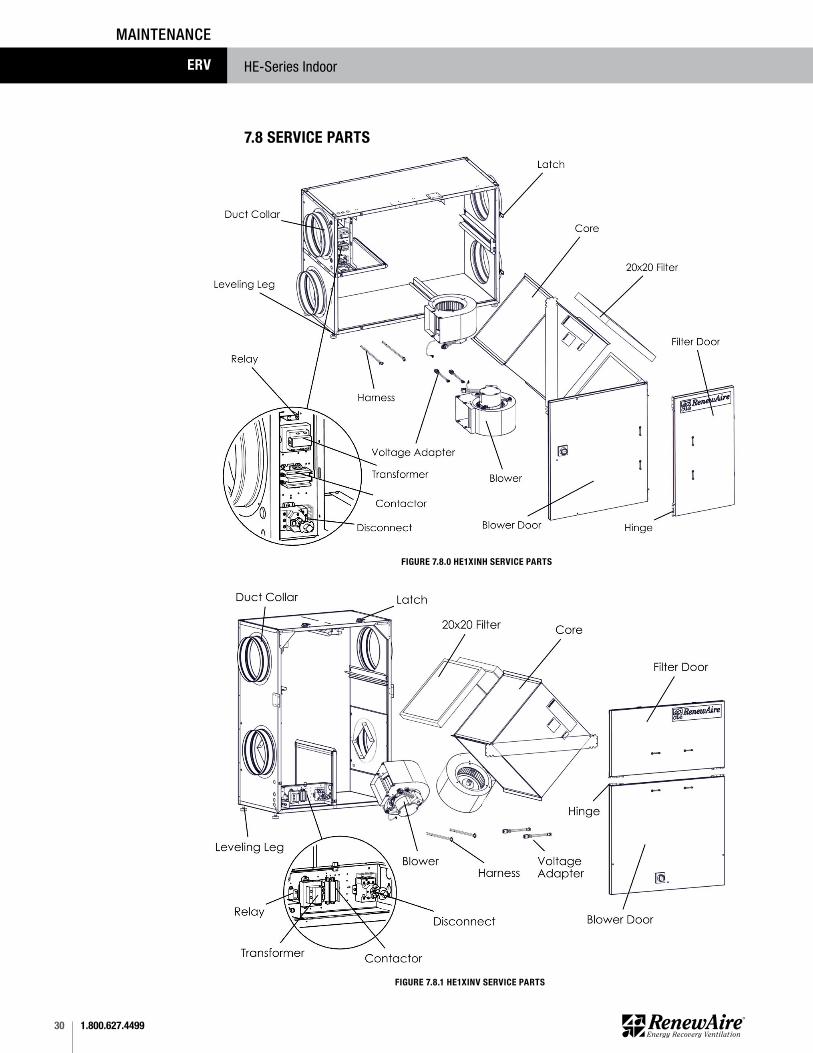
1.800.627.449930
HE-Series IndoorERV
MAINTENANCE
7.8 SERVICE PARTS
FIGURE 7.8.0 HE1XINH SERVICE PARTS
www.renewaire.com (800) 627- 4499 [email protected]
FIGURE 7.8.1 HE1XINV SERVICE PARTS
www.renewaire.com (800) 627- 4499 [email protected]

311.800.627.4499
HE-Series Indoor ERV
FACTORY ASSISTANCE
8.0 TROUBLESHOOTING
In the unlikely event that you need assistance from the factory for a specific issue, make sure that you have the information called for in the Unit Information page in the front of this manual. The person you speak with at the factory will need that information to properly identify the unit.
To contact RenewAire Customer Service:
Call 800-627-4499
Email: [email protected]
9.0 FACTORY ASSISTANCE
If problems occur with a RenewAire ERV, the primary resources for troubleshooting are the unit as-built wiring schematics and the Sequence Of Operation (SOO) for each control scheme.
About RenewAireFor over 30 years, RenewAire has been a pioneer in enhancing indoor air quality (IAQ) in commercial and residential buildings of every size.This is achieved while maximizing sustainability through our fifth-generation, static-plate, enthalpic-core Energy Recovery Ventilators (ERVs) that optimize energy efficiency, lower capital costs via load reduction and decrease operational expenses by minimizing equipment needs, resulting in significant energy savings. Our ERVs are competitively priced, simple to install, easy to use and maintain and have a quick payback. They also enjoy the industry’s best warranty with the lowest claims due to long-term reliability derived from innovative design practices, expert workmanship and Quick Response Manufacturing (QRM).
As the pioneer of static-plate core technology in North America, RenewAire is the largest ERV producer in the USA. We’re committed to sustainable manufacturing and lessening our environmental footprint, and to that end our Waunakee, WI plant is 100% powered by wind turbines. The facility is also one of the few buildings worldwide to be LEED and Green Globes certified, as well as having achieved ENERGY STAR Building status. In 2010, RenewAire joined the Soler & Palau (S&P) Ventilation Group in order to provide direct access to the latest in energy-efficient air-moving technologies. For more information, visit: renewaire.com
Member of the S&P Group Family of Brands
2020 © RenewAire LLC105599_011_MAY20
201 Raemisch Road | Waunakee, WI | 53597 | 800.627.4499 | RenewAire.com