HD View User Guide - ftp.blackbox.comftp.blackbox.com/manuals/A/AC3000A-AC3016A.pdf · Todas las...
42
The HD View JULY 2007 AC3000A AC3008A AC3016A AC3003A AC3004A AC3001A AC3002A Order toll-free in the U.S. 24 hours, 7 A.M. Monday to midnight Friday: 877-877-BBOX FREE technical support, 24 hours a day, 7 days a week: Call 724-746-5500 or fax 724-746-0746 Mail order: Black Box Corporation, 1000 Park Drive, Lawrence, PA 15055-1018 Web site: www.blackbox.com • E-mail: [email protected] CUSTOMER SUPPORT INFORMATION
-
Upload
duongnguyet -
Category
Documents
-
view
214 -
download
0
Transcript of HD View User Guide - ftp.blackbox.comftp.blackbox.com/manuals/A/AC3000A-AC3016A.pdf · Todas las...

The HD View
JULY 2007 AC3000A AC3008A AC3016A AC3003A AC3004A AC3001A AC3002A
Order toll-free in the U.S. 24 hours, 7 A.M. Monday to midnight Friday: 877-877-BBOX FREE technical support, 24 hours a day, 7 days a week: Call 724-746-5500 or fax 724-746-0746 Mail order: Black Box Corporation, 1000 Park Drive, Lawrence, PA 15055-1018 Web site: www.blackbox.com • E-mail: [email protected]
CUSTOMER SUPPORT
INFORMATION


FCC STATEMENT
1
FEDERAL COMMUNICATIONS COMMISSION AND
CANADIAN DEPARTMENT OF COMMUNICATIONS RADIO FREQUENCY INTERFERENCE STATEMENTS
This equipment generates, uses, and can radiate radio frequency energy and if not installed and used properly, that is, in strict accordance with the manufacturer’s instructions, may cause interference to radio communication. It has been tested and found to comply with the limits for a Class A computing device in accordance with the specifications in Subpart B of Part 15 of FCC rules, which are designed to provide reasonable protection against such interference when the equipment is operated in a commercial environment. Operation of this equipment in a residential area is likely to cause interference, in which case the user at his own expense will be required to take whatever measures may be necessary to correct the interference.
Changes or modifications not expressly approved by the party responsible for compliance could void the user’s authority to operate the equipment.
This digital apparatus does not exceed the Class A limits for radio noise emission from digital apparatus set out in the Radio Interference Regulation of the Canadian Department of Communications.
Le présent appareil numérique n’émet pas de bruits radioélectriques dépassant les limites applicables aux appareils numériques de la classe A prescrites dans le Règlement sur le brouillage radioélectrique publié par le ministère des Communications du Canada.

2
HD VIEW
2
Normas Oficiales Mexicanas (NOM) Electrical Safety Statement
INSTRUCCIONES DE SEGURIDAD
1. Todas las instrucciones de seguridad y operación deberán ser leídas antes
de que el aparato eléctrico sea operado.
2. Las instrucciones de seguridad y operación deberán ser guardadas para referencia futura.
3. Todas las advertencias en el aparato eléctrico y en sus instrucciones de operación deben ser respetadas.
4. Todas las instrucciones de operación y uso deben ser seguidas.
5. El aparato eléctrico no deberá ser usado cerca del agua—por ejemplo, cerca de la tina de baño, lavabo, sótano mojado o cerca de una alberca, etc.
6. El aparato eléctrico debe ser usado únicamente con carritos o pedestales que sean recomendados por el fabricante.
7. El aparato eléctrico debe ser montado a la pared o al techo sólo como sea recomendado por el fabricante.
8. Servicio—El usuario no debe intentar dar servicio al equipo eléctrico más allá a lo descrito en las instrucciones de operación. Todo otro servicio deberá ser referido a personal de servicio calificado.
9. El aparato eléctrico debe ser situado de tal manera que su posición no interfiera su uso. La colocación del aparato eléctrico sobre una cama, sofá, alfombra o superficie similar puede bloquea la ventilación, no se debe colocar en libreros o gabinetes que impidan el flujo de aire por los orificios de ventilación.
10. El equipo eléctrico deber ser situado fuera del alcance de fuentes de calor como radiadores, registros de calor, estufas u otros aparatos (incluyendo amplificadores) que producen calor.

NOM STATEMENT
3
11. El aparato eléctrico deberá ser connectado a una fuente de poder sólo del tipo descrito en el instructivo de operación, o como se indique en el aparato.
12. Precaución debe ser tomada de tal manera que la tierra fisica y la polarización del equipo no sea eliminada.
13. Los cables de la fuente de poder deben ser guiados de tal manera que no sean pisados ni pellizcados por objetos colocados sobre o contra ellos, poniendo particular atención a los contactos y receptáculos donde salen del aparato.
14. El equipo eléctrico debe ser limpiado únicamente de acuerdo a las recomendaciones del fabricante.
15. En caso de existir, una antena externa deberá ser localizada lejos de las lineas de energia.
16. El cable de corriente deberá ser desconectado del cuando el equipo no sea usado por un largo periodo de tiempo.
17. Cuidado debe ser tomado de tal manera que objectos liquidos no sean derramados sobre la cubierta u orificios de ventilación.
18. Servicio por personal calificado deberá ser provisto cuando:
A: El cable de poder o el contacto ha sido dañado; u
B: Objectos han caído o líquido ha sido derramado dentro del aparato; o
C: El aparato ha sido expuesto a la lluvia; o
D: El aparato parece no operar normalmente o muestra un cambio en su desempeño; o
E: El aparato ha sido tirado o su cubierta ha sido dañada.

4
HD VIEW
4

CONTENTS
5
Contents 1. Specifications................................................................................. 7 2. Introduction ................................................................................... 9
2.1 Features ..................................................................................... 9 3. HD View components .................................................................. 10
3.1 HD View Transmitter .............................................................. 10 3.2 HD View Receivers.................................................................. 11 3.3 HD View Line Splitters............................................................ 12 3.4 LEDs ....................................................................................... 13 3.5 HD View Video Tuner ............................................................. 13
4. HD View applications .................................................................. 14 5. Installing the system .................................................................... 16
5.1 Pre-installation guidelines........................................................ 16 5.2 The HD View cables ................................................................ 16 5.3 Connecting the cables .............................................................. 16
5.3.1 Connecting to the power supply ......................................... 18 6. Adjusting the picture quality ........................................................ 19
6.1 Downloading a video table....................................................... 20 6.2 Saving and exiting ................................................................... 20
7. HD View system management...................................................... 21 7.1 Installing the Service utility ..................................................... 21 7.2 Connecting the Serial Download cable ..................................... 22 7.3 Using the Service Utility .......................................................... 22
7.3.1 Com port ........................................................................... 23 7.3.2 Topology............................................................................ 23 7.3.3 Auto-detect ........................................................................ 24 7.3.4 Check ................................................................................ 25 7.3.5 Manual .............................................................................. 25 7.3.6 Naming a port.................................................................... 26 7.3.7 Saving a topology .............................................................. 26 7.3.8 Saving a Group.................................................................. 27 7.3.9 Deleting a Group ............................................................... 28
7.4 Controlling the system ............................................................. 28

6
HD VIEW
6
7.4.1 Selecting the ports to command ......................................... 29 7.4.2 Sending commands............................................................ 29
7.5 Tuning Receivers - LR (or Line Splitters) via the Service Utility...................................................................................................... 30 7.6 Remote Tuning ........................................................................ 33 7.7 Service..................................................................................... 36
7.7.1 Firmware ........................................................................... 37 7.7.2 Display Data Channel (DDC) hotkey ................................. 37 7.7.3 Service............................................................................... 38 7.7.4 Transmitter’s Local Serial port .......................................... 38 7.7.5 Security ............................................................................. 38

CHAPTER 1: Specifications
7
1. Specif ications
Resolution
HDTV up to 1080p. Up to 1920x1440 @ 60Hz.
Depending on the cable length and quality
Input/Output video signals Analog signal red, green, blue 0.7v, p-p 75 Ohm
Sync TTL compatible
Horizontal/Vertical sync polarity Positive/Negative
System cable CATx(5/5e/6/7) UTP/ FTP 2x4x24 AWG solid wire cable
Maximum distance 300m / 1,000ft
Skew compensation Up to 63 nsec
DDC Complies with VESA DDC 2 specifications
RS232 connection Full serial = RXD, TXD, DTR, DSR, RTS, CTS
Serial baud rate Up to 57,600 bps
Audio
Stereo Frequency response: 20 Hz to 20 kHz, +/-1 dB. Signal-to-Noise Ratio (SNR): 80 dBA. Total Harmonic Distortion and Noise (THD+N): 0.017%. Stereo crosstalk: -70 dB. Input impedance: 10k Ohms. Line level output; supports multimedia speakers. Maximum I/O levels: 3.1Vp-p (line level).
Serial Transmitter / Transmitter – DCE Receivers - DTE
Operating temperature 5°C to 40°C / 41°F to 104°F
Storage temperature -40°C to 70°C / -40°F to 158°F

8
HD VIEW
8
HD View Transmitter (1, 8, 16 ports) HD View Line Splitter/Line
Splitter - LR Cables & Connectors
VGA In - HDD15M VGA Local - HDD15F Stereo audio In/Out – Jack PL 3.5mm Serial In- DB9F Serial Local- DB9M System Out - 8/16 RJ45 Control – RJ11 Power LED – Green (front panel)
System In - RJ45 System Out - RJ45 Control – RJ11 Power LED – Green (front panel)
Dimensions 292.5x 153.6x41.5mm 138x153.7x41.5mm Power External Adaptor
5VDC 2.5A External Adaptor 5VDC 2.5A
HD View Receiver/Receiver - LR Video Video Tuner Cables & Connectors
System In - RJ45 Screen - HDD15F Audio Out – 3 Jack L,R, L&R Serial Out- DB9M Tuning- potentiometer / RJ11 Power LED – Green (on RJ45)
To Receiver- RJ11 3 button tuning
Dimensions 147x145x26mm (including mounting)
93.7x62.1x28mm
Power External Adaptor 5VDC 1A
Powered from the Receiver

9
CHAPTER 2: Introduction
2. Introduction The HD View system from Black Box is an out-of-band solution for the last step in a digital signage network. HD View combines video, stereo/audio and serial functions for distributing real-time multimedia content from player to multiple screens up to 300m/1,000ft away.
The HD View system distributes Video, Audio and Serial control data from a single content source to up to 128 remote monitors over CAT 5/5e/6/7 UTP media.
With the HD View an administrator can remotely turn the distributed screens on and off, and monitor them either separately or as a unified group. The system also supports Display Data Channel (DDC) signaling, enabling optimal player-screen configuration for better visual experience.
Depending on the cable length the HD View broadcasts the video up to resolutions of 1080p HDTV or 1920x1440 @ 60Hz.
HD View comes with full RS-232 point-to-point, real-time serial communication (including TX, RX, CTS, and RTS) for the extension of serial devices and player to screen command and information transfer. All handshake lines are supported for maximum compatibility with any serial device.
2.1 Features • HD support
• High quality stereo-audio
• 1 to 1, 1 to many serial control
• All speeds up to 57,600
• Distribution over CATx (5/5e/6/7) cable.
Note! No skew cables are not suitable
• Multiple mounting options

10 10
HD VIEW
3. HD View components The HD View system consists of the following components:
• A Transmitter or Transmitter + cables + power supply
• Receivers / Receivers - LR + power supply
• (Optional) Line Splitters / Line Splitters - LR+ Tuning cable+ power supply.
• (Optional) Video Tuner + cable
• CD containing Video Service Utility
3.1 HD View Transmitter The HD View Transmitter comes in the following models:
• HD View Transmitter – p/n AC3000A
• HD View Transmitter 8 port - p/n AC3008A
• HD View Transmitter 16 port - p/n AC3016A
The figure below illustrates the Transmitter 8 port model. The ports are the same for the Transmitter 1 port and 16 port models, except for the number of System ports. The Transmitter has 1 System port and the Transmitter 16 port model has 16 System ports.
1 2 3 4 5 6 7 8
5VDC
CONTROL VIDEO IN
VIDEO OUT LOCAL
SERIAL
AUDIO OUT
AUDIO IN
Systemcables
Audiocable
Powerconnector
Speakers
Videocable
Monitor
Serialcable
LocalSerial
Serial Downloadcable
Figure 1 Transmitter Unit - 8 port

11
CHAPTER 3: HD View components
3.2 HD View Receivers The HD View Receivers come in the following models:
• HD View Receiver - p/n AC3003A. Can be up to 110m/360ft from the Transmitter
• HD View Receiver - LR - p/n AC3004A. Can be up to 300m/1,000ft from the Transmitter
The figures below illustrates the Receiver and Receiver - LR ports
VIDEOSERIAL
L L&R R
To Serial device/connection
To speakers
To screen
}
Figure 2 Receiver and Receiver - LR – side 1
5VDC SYSTEM TUNING
Systemcable
Power connector
Tuningadjuster
Figure 3 Receiver – side 2
5VDC SYSTEM TUNING
Systemcable
Serial Downloadcable
Power connector Figure 4 Receiver - LR – side 2

12 12
HD VIEW
3.3 HD View Line Splitters Add Line Splitters / Line Splitters - LR to use for clusters or to increase the number of Receivers in the system up to 128 – When using the Transmitter 16 port.
The Line Splitters come in the following models:
• Line Splitter - p/n AC3001A. Receivers can be up to 110m/360ft from Transmitter
• Line Splitter - LR - p/n AC3002A. Receivers can be up to 300m/1,000ft from Transmitter)
The figure below illustrates the Line Splitter / Line Splitter - LR ports.
SYSTEM IN5VDC
SYSTEM OUT
Powerconnector
Systemcables to Receivers
TUNING
Serial Downloadcable
System cableto Broadcaster Figure 5 Line Splitter

13
CHAPTER 3: HD View components
3.4 LEDs The table below explains the functions of all the LEDs of the units in the system.
Unit LED Function
Transmitter Front panel - Green Power indicator
Receiver / Receiver - LR
Rear panel - RJ45 System port. Green / Yellow
Green - Power indicator
Yellow solid – unit is connected to the system.
Yellow blinking – Bi-directional RS232 communication (only possible with one Receiver / Receiver - LR at a time).
Line Splitter / Line Splitter - LR
Rear panel - RJ45 System port. Green / Yellow
Green - Power indicator
Yellow blinking – unit is connected to the system
3.5 HD View Video Tuner The optional Video Tuner p/n AC3006A is used to manually tune Receivers - LR / Line Splitters or to download preset tuning parameters. The figure below illustrates the Video Tuner.
Figure 6 Video Tuner

14 14
HD VIEW
4. HD View applications The figures below illustrate the versatility of the HD View system.
Figure 7 shows a basic installation with a Receiver and Receiver - LR. Receivers can be up to 110m/360ft away from the Transmitter. Receiver - LR can be up to 300m/1,000ft away from the Transmitter.
Player
Transmitter
Receiver - LR
Receiver110m/360ft
300m/1,000ft
Figure 7 HD View basic installation
Figure 8 shows a Line Splitter with connected Receivers up to 110m from the Transmitter.
Receivers
Line Splitter100m/330ft
10m/33ft
Player
Transmitter
Figure 8 Short cluster
Figure 9 shows a Line Splitter - LR with connected Receivers up to 300m from the Transmitter.
Line Splitter - LR
280m/920ft20m/66ft
Player
Transmitter
Receivers
Figure 9 Long cluster
Receiver
Line Splitter
100m/330ft 10m/33ft
Player
Transmitter Receiver - LR
200m/660ft

15
CHAPTER 4: HD View applications
Figure 10 and Figure 11 show different mixed installations with different combinations of Line Splitter and Line Splitter - LR and Receiver and Receiver - LR.
Receiver
Line Splitter
100m/330ft 10m/33ft
Player
Transmitter Receiver - LR
200m/660ft
Figure 10 Mixed installation 1
Receiver
10m/33ft
Player
Transmitter/BroadcasterReceiverLong
200m/660ft
Line SplitterLong
100m/330ft
Figure 11 Mixed installation 2

16 16
HD VIEW
5. Installing the system 5.1 Pre-installation guidelines
Place cables away from fluorescent lights, air conditioners, and machines that are likely to generate electrical noise.
5.2 The HD View cables The HD View cables are illustrated below.
Video cable
Stereo Audio cable
Serial Extender cable
Serial Download cable
Figure 12 Cables
5.3 Connecting the cables Connect the cables as illustrated in Figure 13 below.
Transmitter connections
1. Connect the Video cable to the Transmitter Video In port and the Computer’s Video card.
2. Connect the Serial Extender cable to the Transmitter Serial port and the Computer’s Serial port.
3. Connect the Stereo Audio cable to the Transmitter Audio in port and the Computer’s Mic port.
4. To use the Video Service Utility, connect the Serial Download cable to the Transmitter Control port and the Computer’s Serial port.

17
CHAPTER 5: Installing the system
5. (Optional) Connect a monitor to the Transmitter Video Out port.
6. (Optional) Connect speakers to the Transmitter Audio Out port.
Receiver /Receiver - LR connections
1. Connect the screen to the Video port.
2. Connect the audio/speakers to the Audio port/s. Where the audio/speakers have one connector, connect it to the L&R port. Where the audio/speakers have two connectors connect them to the L port and the R port.
3. Where relevant connect the Serial connection to the Serial port
Connecting CATx cables
Connect the CATx cables between the System ports of the Transmitter and Receivers/Receivers - LR.
Where there are Line Splitters/ Line Splitters - LR:
1. Connect the CATx cables between the System ports of the Transmitter and the System In ports of the Line Splitters/ Line Splitters - LR.
2. Connect the CATx cables between the System Out ports of the Line Splitters/ Line Splitters - LR and the System ports of the Receivers/Receivers - LR.

18 18
HD VIEW
HD ViewTransmitter
CATx cable toReceiver unit
Playercomputer
CATx cables toReceivers orLine Splitters
To Audio Out
To Mic. port
Stereo Audio cable
To Serial port
ToSerialport
1 2 3 4 5 6 7 8
5VDC
CONTROL VIDEO IN
VIDEO OUT LOCAL
SERIAL
AUDIO OUT
AUDIO IN
To Audio In
VIDEOSERIAL
L L&R R
5VDC SYSTEM TUNINGReceiver side 1
Receiver side 2
Video cable
Serial Extender cable
To Serial portSerial Download cable
SYSTEM IN5VDC
SYSTEM OUT
TUNING
CATx cables toReceivers
ScreenSpeakers /Audio
Serial port /device
Line Splitter
Figure 13 Connection diagram
5.3.1 Connecting to the power supply
Connect the Transmitter and Line Splitter units to the power supply with 5 VDC, 2.5A from the external power adapters provided. The Receivers come with 5VDC 1A external power adapters.
Ensure correct polarity (Center negative) and voltage.
Once the system is connected the HD View system broadcasts to all remote monitors/speakers.
Note! You can use the Service Utility provided to broadcast content to specific monitors or groups of monitors, see HD View system management on page 21 below.

19
CHAPTER 6: Adjusting the picture quality
6. Adjusting the picture quality
When the broadcasted picture needs adjusting:
For the Receiver turn the Tuning adjuster – see Figure 3, using a small screwdriver.
The Receiver - LR / Line Splitters can be tuned either via the Service Utility, as explained on page 30, or by using the optional Video Tuner as follows:
1. Connect the Video Tuner to the Tuning port of the Receiver – LR / Line Splitter, using the supplied cable. Once connected, Black Box HD View appears in the LCD.
2. Press the Menu key to repeatedly scroll between the following functions:
• Preset tables
• Red
• Green
• Blue
• Luminance (Lum)
• Equalization (Equ)
• Save / ESC
3. Select the desired function and adjust it using the up and down arrow keys.
4. Once the adjustment is satisfactory, press the Menu key to scroll to next function.

20 20
HD VIEW
6.1 Downloading a video table To download a video table:
1. Scroll to Preset tables
2. Use the arrow keys to browse through all the predefined tables.
3. When you reach the desired table, press the Menu key. MNU=SAVE appears in the LCD and the table downloads. During downloading the LCD message blinks.
4. After downloading one table, a different table can be selected and downloaded.
6.2 Saving and exiting To save all settings in the Receiver - LR or Line Splitter unit:
1. Scroll to Save / ESC
2. Press the up arrow to save all changes and exit or press the down arrow to disregard all changes and exit.

21
CHAPTER 7: HD View system management
7. HD View system management
The HD View system comes with a Service utility to configure and control the system. Use the Service utility to:
• Define up to 16 Groups of monitors – (a specific monitor may belong to several Groups).
• Broadcast/disconnect video and/or audio and/or serial data to each monitor or to Groups of monitors.
• View system topology and switching status of each monitor.
• Remotely tune a monitor.
• Remotely upgrade each system component firmware/software or FPGA
• Configure DDC settings
• Return to the factory default settings
7.1 Installing the Service utility The Service utility is located on the supplied CD and on our ftp Site ftp://ftp.blackbox.com in the Communication folder in a sub-folder named, “HD View Service Utility”.
Install the Service utility on a computer with the following system requirements:
• Intel® Pentium® II or equivalent processor
• Windows XP Professional, Home Edition, or Tablet PC Edition with Service Pack 2; Microsoft® Windows® 2000 with Service Pack 4; Windows 2003 Server; or Windows Vista™
• 128MB of RAM
• 10MB of available hard-disk space

22 22
HD VIEW
For full functionality of the Service utility the HD View system (Transmitter, Line Splitters and Receivers) must be connected and switched on. You can however configure the system topology manually even when the system is not operational.
7.2 Connecting the Serial Download cable Connect the Serial Download cable to the Control port of the Transmitter and a Serial port of the computer which has the Service Utility installed.
1 2 3 4 5 6 7 8
5VDC
CONTROL VIDEO IN
VIDEO OUT LOCAL
SERIAL
AUDIO OUT
AUDIO IN
SerialDownloadcable
To computer’sSerial port
Figure 14 Connecting the Serial Download cable
7.3 Using the Service Utility To open the Service Utility, choose Start/Programs/HD View Service Utility/ HD View Service Utility. The Control window appears, see Figure 15.
Figure 15 Control window

23
CHAPTER 7: HD View system management
7.3.1 Com port
Choose Tools/Options. The Preferences window appears see Figure 16. In the Com port field select the Com port to which the Serial Download cable is connected to.
Figure 16 Preferences window
7.3.2 Topology
To utilize the Service Utility functions you must configure the system topology. To configure the system topology, click the Topology tab or select View/ Topology. The following appears.
Title line(Indicates if theUtility is onlineor offline)
Figure 17 Topology tab
You can detect the topology automatically or configure it manually.

24 24
HD VIEW
7.3.3 Auto-detect
Note! Auto-detection only works if the Service Utility is online. Check the Title line of the Service Utility window, see Figure 17. When offline, connect to the system by choosing File/Connect.
To auto-detect the topology, click and when prompted click Yes.
A detected topology appears on the left showing all connected HD View units, as in the following figure.
Figure 18 Auto-detected topology
Note! You can detect the current topology at any time by pressing . This fully updates all connected and disconnected ports.
Note! Auto-detect, deletes all names given to particular ports. Naming ports is explained on page 26.
Tip! Hold the mouse over any of the rows in the menu tree or over any button. A callout appears with information about the device or button function.

25
CHAPTER 7: HD View system management
7.3.4 Check
When units have been connected or disconnected since last detecting the topology you can check for any changes to the topology.
To do so:
1. Click . Any new units detected appear as an connected but undefined . You must still define the unit.
2. To define the units connected to the ports, click the checkbox of a port or a number of ports that have the same device connected.
3. Click . A drop-down menu appears.
4. Select the device type.
Note! When the device is a Line Splitter, repeat the process of defining the connected devices for each port of the Line Splitter.
Note! Check does not update the topology, it detects any new connections and units that are
disconnected appear with a yellow exclamation mark .
Update
To add new devices to the present topology click . The new devices appear. Units that are disconnected appear with a yellow exclamation mark .
7.3.5 Manual
You can display the topology manually whether the system is online or offline.
To display the topology manually:
1. Click . A drop-down menu appears.
2. Select the connected Transmitter. The selected topology appears on the left, see Figure 19. If the Service Utility is online you can

26 26
HD VIEW
see which ports have devices connected. In Figure 19 a device is connected to port 4.
Figure 19 Manually displayed topology
3. To define the units connected to the ports, click the checkbox of a port or a number of ports that have the same device connected.
4. Click . A drop-down menu appears.
5. Select the device type.
Note! When the device is a Line Splitter, repeat the process of defining the connected devices
for each port of the Line Splitter.
7.3.6 Naming a port
To give a port an identifying name:
1. Check the port number (ensure that no other ports are checked). In the manual section, Set device name: appears.
2. Type a new name for the port - You can give ports identical names. This name appears immediately on the left.
7.3.7 Saving a topology
To save a topology choose File/Save or Save as. Save the topology.

27
CHAPTER 7: HD View system management
To restore the topology choose File/Restore. Find the saved topology and click Open. The stored topology appears.
Note! The most recent saved topologies appear in the File menu.
7.3.8 Saving a Group
You can save a Group to include particular ports. Once defined, you can send instructions to the defined Group without needing to choose the individual ports.
To save a Group:
1. Select the ports you want to include in the Group.
2. Click . The Enter name box appears.
3. Type a name for the group and click OK. The Group appears on the left.
Groups appearhere
Figure 20 Saving a Group
To see the selected ports of a Group, hold the mouse over the Group name or folder or check box, a callout appears showing the selected ports.

28 28
HD VIEW
7.3.9 Deleting a Group
To delete a Group:
Select the Group and click .
7.4 Controlling the system To control the system:
Click the Control tab or choose View/Control, the Control window appears, see Figure 21.
Connecteddevicesappear here
Control icons
Topology
Figure 21 Control window
The table below explains the functions of the Control icons:
Icon Function
Video broadcasting to remote unit
Audio broadcasting to remote unit
Serial command to remote unit
Bi-directional Serial command

29
CHAPTER 7: HD View system management
7.4.1 Selecting the ports to command
You can select the ports to command in any of the following ways.
From the topology on the left hand side:
Tick the individual checkboxes of the units you want to send a command. Or tick the desired Group – all commands will then be sent to all units in the Group.
From the icons on the right hand side:
Click an icon to select it. To select more than one icon, hold down Shift or Ctrl and select the desired icons.
Selecting all
To select all:
Choose Edit/Select All.
7.4.2 Sending commands
Once the desired units are selected send the desired command by pressing the appropriate Control icon. By default all signals (video, audio, Serial) are broadcast.
Sending/blocking video
Click to toggle between sending and blocking video. When
receiving video the device icons appear like this: .
When not receiving video the device icons appear like this: .
Sending/blocking Audio
Click to toggle between sending and blocking audio. When
receiving audio the device icons appear with a speaker like this: .

30 30
HD VIEW
Sending/blocking a Serial command
Click to toggle between sending and blocking a Serial command. When sending a Serial command the device icons appear with an arrow
like this: .
Sending/blocking a bi-directional Serial command
When sending a Serial command, you can send a bi-directional Serial command to a single Receiver / Receiver - LR.
Click to send the bi-directional Serial command. The device icon
appears with a double arrow like this: . Click again to block the bi-directional Serial command. You can then send the bi-directional Serial command to a different Receiver / Receiver - LR.
7.5 Tuning Receivers - LR (or Line Splitters) via the Service Utility
You can tune the Receivers - LR / Line Splitters with the Service Utility from the Transmitter position or from the Receiver - LR / Line Splitter itself. The advantage of tuning from the Receiver - LR, is that you can see the tuning on the screen as you perform it. From the Line Splitter position you can be closer to the screen than from the Transmitter position.
To tune from the Transmitter position:
Connect the Serial Download cable to the Control port of the Transmitter and the Serial port of a computer which has the Service Utility installed.
To tune from the Receiver - LR or Line Splitter position:
Connect the Serial Download cable to the Receiver - LR or Line Splitter Tuning port and the Serial port of a computer containing the Service Utility. See the figure below.

31
CHAPTER 7: HD View system management
5VDC SYSTEM TUNING
Serial Download cable
ToTransmitter
To computer’sSerial port
Figure 22 Connecting the Serial Download cable to the Receiver - LR
1. Open the test card located on our ftp Site ftp://ftp.blackbox.com in the Communication folder in a sub-folder named, “HD View Test Card”. Or open the Service Utility and choose Tools/Options, the Preferences window appears, see Figure 16 above. Check Show Skew Picture. When you click the Tuning tab the test card appears in the background. See Figure 23. This image will help you get the best screen image. It can also help to correct skew.
Figure 23 Test card
2. Click the Tuning tab or select View/Tuning. The Tuning window appears, see Figure 24.

32 32
HD VIEW
Figure 24 Tuning window
3. The Drop-down menu contains preset tuning configurations for distances of between 1m and 300m.
Note! These presets were made using a test cable which may not be an exact match for the cable that you are using. Choose the preset distance that is closest to the actual distance in meters between the Player and remote screen.
4. For fine tuning use the sliding bars to adjust the image. The bars are as follows.
Luminance – image brightness
Equalization – image sharpness
Red, Green, Blue
Red, Green and Blue are for red, green and blue delay. When transmitting video over CATx cables a horizontal misalignment (skew) between the red, green and blue components inevitably occurs. This is because the different length of each pair causes the signals to reach the monitor at different times.
To see which signal is slower or faster look at the test card and see which of the colors are not aligned. For example in Figure 25, red is the slowest color. You would therefore delay green and blue until they align with red.

33
CHAPTER 7: HD View system management
Faster
Slower
Red
Green
Blue
Figure 25 RGB signals
5. Once you have a satisfactory image, press Store to keep the present tuning configuration.
6. Click Save Preset to save the tuning configuration for future use. The Enter Name box appears.
7. Type a name for the preset and click OK. The tuning configuration now appears in the drop-down menu.
Delete preset - to delete a tuning configuration from the drop-down menu, click Delete preset.
Restore – If after changing values you change your mind, you can restore the values to how they were the last time the Store button was pressed by pressing Restore.
7.6 Remote Tuning You can tune the Receiver - LR and Line Splitters from any laptop or other mobile device via a web browser. Through the browser you access the player running the Service utility via the local network. This enables you to tune the screen when standing in front of it without the need to be physically connected to the Receiver - LR / Line Splitter. The Service Utility must be installed on the players but is not needed on the remote tuning device. Figure 26 illustrates the basic concept.

34 34
HD VIEW
Remote tuner at thescreen
Receivers
Line Splitter
Service Utilityinstalled here
Player - IP: 192.168.111.132
LAN
http://192.168.111.132
Transmitter
Figure 26 Remote tuning
At the player the setup is done as follows:
1. Connect the Serial Download cable to the Transmitter and player.
2. Open the Service Utility and choose Tools/Options, the Preferences window appears, see Figure 16 above.
3. Select the Enable Remote Control checkbox, the software starts a small web server in the background allowing other computers on the network to access it. The Check Remote Control button un-grays. Click the button to display a local browser to indicate that the remote option is enabled and functioning.
4. To verify the IP address of the player, click Start/Run, type “CMD” press Enter, type “IPConfig” press Enter. The IP address appears.
The tuning at the remote laptop/device is done as follows:
1. Open a browser and type the IP address of the player. For example in Figure 26 the remote tuner accesses the tuning facility by typing the IP address http://192.168.111.132.
2. Press Enter. A list of all Receivers - LR and Line Splitters connected to the player appears, see Figure 27.

35
CHAPTER 7: HD View system management
Figure 27 Select device web page
3. Select a unit and press Submit. The tuning page appears, see Figure 28.
Figure 28 Remote tuning web page
4. Adjust the setting until you have a satisfactory picture. Press Submit to activate the new values. Press Store to save the new values. Restore – If after changing values you change your mind, you can restore the values to how they were the last time the Store button was pressed by pressing Restore.
5. Press reset to return to the default values.
36 36
HD VIEW
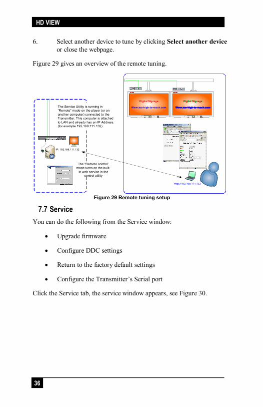
6. Select another device to tune by clicking Select another device or close the webpage.
Figure 29 gives an overview of the remote tuning.
The Service Utility is running in“Remote” mode on the player (or onanother computer) connected to theTransmitter. This computer is attachedto LAN and already has an IP Address.(for example 192.168.111.132)
SDTFT450
The “Remote control”mode turns on the built-
in web service in thecontrol utility
IP: 192.168.111.132
Http://192.168.111.132
Digital Signage
Www.too-high-to-reach.com
Digital Signage
Www.too-high-to-reach.com
Digital Signage
Www.too-high-to-reach.com
Digital Signage
Www.too-high-to-reach.com
Figure 29 Remote tuning setup
7.7 Service You can do the following from the Service window:
• Upgrade firmware
• Configure DDC settings
• Return to the factory default settings
• Configure the Transmitter’s Serial port
Click the Service tab, the service window appears, see Figure 30.

37
CHAPTER 7: HD View system management
Figure 30 Service window
7.7.1 Firmware
Upgrade firmware to improve functionality and fix bugs. Firmware updates can be found on our ftp Site ftp://ftp.blackbox.com in the Communication folder in a sub-folder named, “HD View firmware”.
1. Save the firmware update on your hard drive.
2. Select the unit you want to upgrade, Transmitter etc.
3. Click the Query button, a list of the firmware versions you can update appears: Hardware, firmware, loader or FPGA. When you click one of them, the current version appears.
4. Click Update. The Open box appears.
5. Find the firmware update and upload it.
7.7.2 Display Data Channel (DDC) hotkey
Display Data Channel (DDC) is a VESA standard for exchanging information between a monitor and a video adapter.
Update the DDC during the initial installation of the system, this will enable emulation of the DDC information to the computer when it boots the next time.

38 38
HD VIEW
To update the DDC:
1. Select a Receiver and press Get DDC to read the DDC from the monitor attached to it and save it to file.
2. Select the Transmitter and press Set DDC to read from the saved file and upload it to the Transmitter.
Note! Update the DDC information if you add or replace a monitor with a different resolution / refresh rate.
Get stored DDC button – Press to get the DDC stored in the Transmitter flash memory and save it as a file on the computer’s hard disk. This DDC data will be read by the player connected to the Transmitter.
7.7.3 Service
To restore factory defaults press Restore to factory settings.
Note! All configuration and tuning adjustments will be lost.
7.7.4 Transmitter’s Local Serial port
This is for Serial control of the local monitor. There are 2 options.
• Enable - Connects the system serial data to the local monitor- downstream only.
• Bi directional - Enables serial bi-directional connections with the local monitor – like any remote monitor in the system.
7.7.5 Security
Choose Tools/Options. In the Preferences window click Security. The Security screen appears.

39
CHAPTER 7: HD View system management
Figure 31 Security window
Here you can set up a password to require password access to the service Utility.

40 40
HD VIEW
© Copyright 2007. Black Box Corporation. All rights reserved.
1000 Park Drive Lawrence, PA 15055-1018 724-746-5500 Fax 724-746-0746