HD 800 - 1000
142
UN21-0456BO HD 800 - 1000 ORTECO S.r.l. Via 2 Giugno, 19 40011 Anzola Emilia (Bo) - Italia Tel. +39 051 731051 Fax +39 051 731925 mail: [email protected] www.orteco.com PILE DRIVER ON CRAWLER USE AND MAINTENANCE MANUAL Manual code: 170310 Language: english Edition: 01/2017 IV th Series Translations of the original instructions in italian language Serial number
Transcript of HD 800 - 1000

UN21-0456BO
HD 800 - 1000
ORTECO S.r.l. Via 2 Giugno, 19
40011 Anzola Emilia (Bo) - ItaliaTel. +39 051 731051Fax +39 051 731925
mail: [email protected]
PILE DRIVER ON CRAWLER
USE AND MAINTENANCE MANUAL
Manual code: 170310
Language: english
Edition: 01/2017
IVth Series
Translations of the original instructions in italian language
Serial number

SUMMARY
1 GENERAL INFORMATION ..........................................................................................................................12 TECHNICAL INFORMATION .....................................................................................................................53 SAFETY INFORMATION .......................................................................................................................... 184 HANDLING AND TRANSPORTATION ................................................................................................. 215 ADJUSTMENT INFORMATION .............................................................................................................. 266 INFORMATION FOR USE ........................................................................................................................ 317 MAINTENANCE INFORMATION ........................................................................................................... 768 BREAKDOWN INFORMATION ............................................................................................................... 859 INFORMATION CONCERNING REPLACEMENTS ............................................................................. 86A ENCLOSURES ............................................................................................................................................. 91
ANALYTICAL INDEX
AAccessories ....................................................................................................................................................... 16Adjusting of “PROXIMITY device” that stops the hammer’s down stroke .................................. 27Adjusting the “laser device” that stops the hammer’s down stroke ............................................. 29Adjusting track tension ................................................................................................................................ 26Advice for handling and transportation ................................................................................................ 21Aim of the manual ............................................................................................................................................1Analytical index .................................................................................................................................................IIIAnnexed documentation ...............................................................................................................................3Assembly of pile driver on the crawler ................................................................................................... 25Automatic verticality system - instructions for use .......................................................................... 65
BBlade raiser - instructions for assembly, use, and maintenance .................................................... 59
CChecking and cleaning the supplementary air filter ......................................................................... 79Cleaning and lubrication of hammer lifting chain ............................................................................. 83Controls to run the machine ...................................................................................................................... 33Core borer - instructions for assembly, use, and maintenance ...................................................... 45
DDashboard controls (base version) .......................................................................................................... 32Declaration of conformity ........................................................................................................................... 12Description of the controls ........................................................................................................................ 31Disclaimer notice ...............................................................................................................................................3Drilling machine - instructions for assembly, use, and maintenance .......................................... 48Drill - instructions for assembly, use, and maintenance ................................................................... 54
EElectric generator - use and maintenance procedures..................................................................... 58Emergency stop .............................................................................................................................................. 75Engine identification ........................................................................................................................................3Environmental operating limits ................................................................................................................ 11Environmental protection precautions .................................................................................................. 20
FFire-prevention and first aid measures ................................................................................................... 20
GGas emissions .................................................................................................................................................. 11General description ..........................................................................................................................................5General safety warnings .............................................................................................................................. 18Glossary of terms ...............................................................................................................................................4
Gripper for metal pile extraction - instructions for assembly, use, and maintenance .......... 43
HHandling and transport safety precautions .......................................................................................... 19Hose check ........................................................................................................................................................ 81Hydraulic oil level check .............................................................................................................................. 82
IInformation and safety signs .........................................................................................................................8Intended uses .....................................................................................................................................................6
LLifting the machine ....................................................................................................................................... 22Lifting the pile driver ..................................................................................................................................... 23Lifting the truck............................................................................................................................................... 22Lighting - instructions for working at night or in poor visibility conditions ............................. 73Long out-of-use periods .............................................................................................................................. 74Lubricant comparison table ....................................................................................................................... 84Lubrication diagram ...................................................................................................................................... 78
MMachine cleaning ........................................................................................................................................... 83Magnets - instructions for assembly, use, and maintenance ......................................................... 69Main parts ............................................................................................................................................................5Maintenance register ..................................................................................................................................127Manufacturer and machine identification details .................................................................................2
NNut and bolt check ........................................................................................................................................ 79Nuts and bolts tightening torques chart ............................................................................................... 84
OOperational stop ............................................................................................................................................. 75Operation controls ......................................................................................................................................... 34Operator training ...............................................................................................................................................6Overall dimensions ........................................................................................................................................ 10
PPile driving procedure .................................................................................................................................. 40Pointed bit - instructions for assembly, use, and maintenance ..................................................... 62Procedure for getting on and off the transport means .................................................................... 23Procedure for use of the macro tilt .......................................................................................................... 42
RRe-commissioning ......................................................................................................................................... 74Refuelling .......................................................................................................................................................... 74Replacing hosing ............................................................................................................................................ 88Replacing supplementary air filter cartridges ..................................................................................... 87Replacing the chain ....................................................................................................................................... 89Replacing the delivery line filter cartridge (high pressure) ............................................................. 87Replacing the discharge filter cartridge (low pressure) ................................................................... 86Replacing the stroke plate .......................................................................................................................... 89Replacing the track reduction gear oil ................................................................................................... 88Residual risks .......................................................................................................................................................6
SSafety advice concerning use .................................................................................................................... 31Safety advice for maintenance .................................................................................................................. 76Safety advice for the adjustments ............................................................................................................ 26Safety advice in case of faults .................................................................................................................... 85Safety advice in case of replacements .................................................................................................... 86Safety devices ....................................................................................................................................................7Safety instructions for adjustment and maintenance ...................................................................... 19

Scrapping the machine ................................................................................................................................ 90Shifting on slopes procedure ..................................................................................................................... 39Shifting procedure ......................................................................................................................................... 38Sound emissions ............................................................................................................................................. 10Starting the engine ........................................................................................................................................ 36Starting the engine with the auxiliary battery .................................................................................... 37Summary .............................................................................................................................................................IIISupplements .................................................................................................................................................... 17System for adjusting/reducing the hammer drill frequency - instructions for use ................ 67System for measuring the distance between the piles - instructions for assembly, use, and maintenance ........................................................................................................................................... 71
TTechnical assistance procedure....................................................................................................................3Technical characteristics .................................................................................................................................9Track gearmotor oil level check ................................................................................................................ 81Track tension check ....................................................................................................................................... 82Transportation procedure ........................................................................................................................... 21
UUnauthorised uses ............................................................................................................................................6Use and operation safety precautions .................................................................................................... 18Use in cold environmental conditions .................................................................................................... 35
VVersions .............................................................................................................................................................. 13
WWarranty ...............................................................................................................................................................3


English language 1 Use and maintenance
GENERAL INFORMATION 1
Aim of the manual
This manual, which is an integral part of the machine, has been prepared by the manufac-turer to provide the operator with the necessary information and criteria for the use and maintenance of the machine.
The original instructions are provided by the manufacturer in English. To meet legal or sales requirements, the manufacturer may provide the instructions in other languages.
Certain illustrations in the manual show the machine with the safety devices and/or guards removed only in order to make it easier to understand the operations to be performed. The machine must never be used without the safety devices or guards �tted.
The pictures may di�er from the actual machine con�guration, but this does not a�ect the instructions.
The manufacturer reserves the right to make changes to the manual without prior notice, with the exception of changes concerning the level of safety.
The manual must be kept, for future reference, until the machine is scrapped.
If the machine is sold, the seller is required to pass on the manual to the new owner.
In the case of discordant information between the machine manual and the attached man-uals, the machine manual must be considered valid.
The symbols shown in this manual are designed to highlight the operations involving a certain level of risk in safety terms or important information.
DANGER
This indicates information or procedures which, if not strictly followed, cause death or serious personal injury.
WARNING
This shows information or procedures which, if not followed, may cause death or seri-ous personal injury.
CAUTION
This shows information or procedures which, if not followed, may cause slight per-sonal injury.
NOTICE
This shows information or procedures which are important to follow in order to pre-vent malfunctions or physical damage.
UN21-0512AP
AN
BC
DE
FG
HL
M
X
Y
W
Z
R
English language 2 Use and maintenance
GENERAL INFORMATION 1Manufacturer and machine identi�cation details
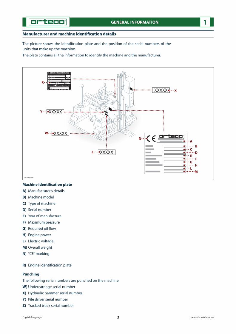
The picture shows the identi�cation plate and the position of the serial numbers of the units that make up the machine.
The plate contains all the information to identify the machine and the manufacturer.
Machine identi�cation plate
A) Manufacturer’s details
B) Machine model
C) Type of machine
D) Serial number
E) Year of manufacture
F) Maximum pressure
G) Required oil �ow
H) Engine power
L) Electric voltage
M) Overall weight
N) “CE” marking
R) Engine identi�cation plate
Punching
The following serial numbers are punched on the machine.
W) Undercarriage serial number
X) Hydraulic hammer serial number
Y) Pile driver serial number
Z) Tracked truck serial number

UN21-0513AP
English language 3 Use and maintenance
GENERAL INFORMATION 1
Engine identi�cation
Engine identi�cation data is shown on the identi�cation plate applied to the engine.
For the meaning of the data contained on the plate see the engine manufacturer’s use and maintenance manual.
Technical assistance procedure
For technical assistance (machine malfunction, failure, etc.) contact the nearest technical assistance service or the manufacturer.When requesting technical assistance, the data shown on the machine’s identi�cation plate, the work hours shown on the hour meter and the type of failure must be reported.
For motor technical assistance (engine malfunction, failure, etc.) contact the nearest techni-cal assistance service of the engine manufacturer (see enclosed manual).
Disclaimer notice
The manufacturer cannot be held responsible for the following:- use of the machine by untrained and/or unauthorised personnel;- improper use of the machine;- failure to carry out maintenance;- unauthorised modi�cations or repairs;- use of non-original spare parts or parts not designed speci�cally for the model con-
cerned.
Warranty
The warranty clauses are speci�ed in the sales contract valid at the time of purchase of the machine.
Annexed documentation
The following documentation is supplied to the Customer together with the use and main-tenance manual.- “CE” declaration of conformity of the machine - Engine maintenance booklet- Safety data sheets for fuel and lubricants.

English language 4 Use and maintenance
GENERAL INFORMATION 1
Glossary of terms
Version: type of machine that features technical and performance di�erences with respect to the standard model.
Accessory: unit that increases the machine’s functionality for speci�c operations.The accessory must be requested by the customer when placing the order.
Supplement: component or unit that completes the machine, which is not included in the standard model.The supplement must requested by the customer when placing the order.
Routine maintenance: the set of interventions needed to guarantee the machine a long working life, in good working order, and to ensure safety requirements are always met.
Special maintenance: set of operations that are carried out in case of a sudden failure to restore the initial operating conditions.
Operator: trained person who has been authorised by the respective manager.It is the operator's duty to ensure the operational tasks and daily routine maintenance out-lined in this manual are carried out safely.
Maintenance engineer: trained person who has been authorised by the respective man-ager.It is the maintenance engineer's duty to ensure the routine maintenance work on the ma-chine requiring speci�c technical skills is carried out safely.The procedures to follow for such work are described in this manual.
Specialist technician: person appointed and authorised by the manufacturer or by the agent thereof.It is the specialist technician's duty to ensure work is carried out safely in terms of routine and special maintenance work on the machine requiring speci�c technical skills or particu-lar abilities.The procedures to follow for such work are described in speci�c instructions.
UN21-0514AP
A C
B
H
D
G
F
L
E
MM
English language 5 Use and maintenance
TECHNICAL INFORMATION 2
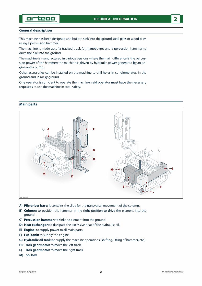
General description
This machine has been designed and built to sink into the ground steel piles or wood piles using a percussion hammer.
The machine is made up of a tracked truck for manoeuvres and a percussion hammer to drive the pile into the ground.
The machine is manufactured in various versions where the main di�erence is the percus-sion power of the hammer; the machine is driven by hydraulic power generated by an en-gine and a pump.
Other accessories can be installed on the machine to drill holes in conglomerates, in the ground and in rocky ground.
One operator is su�cient to operate the machine; said operator must have the necessary requisites to use the machine in total safety.
Main parts
A) Pile driver base: it contains the slide for the transversal movement of the column.B) Column: to position the hammer in the right position to drive the element into the
ground.C) Percussion hammer: to sink the element into the ground.D) Heat exchanger: to dissipate the excessive heat of the hydraulic oil.E) Engine: to supply power to all main parts.F) Fuel tank: to supply the engine.G) Hydraulic oil tank: to supply the machine operations (shifting, lifting of hammer, etc.).H) Track gearmotor: to move the left track.L) Track gearmotor: to move the right track.M) Tool box

English language 6 Use and maintenance
TECHNICAL INFORMATION 2Intended uses
This machine has been designed and built to sink metal piles for guard-rails, wood piles and metal piles for photovoltaic systems.Using special accessories approved by the manufacturer, it is possible to extract piles, make holes and drill (see “Accessories”).Any other use is considered improper and is therefore forbidden.
Unauthorised uses
The machine must be used in conformity with its technical characteristics; it is forbidden to make modi�cations or use the machine for improper uses.It is prohibited to use of the machine in potentially explosive atmospheres.It is prohibited to use the machine with equipment not approved by the manufacturer.It is prohibited to use the machine to transport people.It is prohibited to use the machine to lift people with the percussion hammer.It is prohibited to use the machine to drive piles, make holes on manufactured goods or drill the ground when the column is not perfectly vertical.It is prohibited to drive the machine on the roads as it is not approved for road use.It is prohibited to use the installed pile extraction clamp, corer and drill to drive piles.It is prohibited to extract metal piles from concrete.It is prohibited to activate the track movement or correct the position or tilt of the vertical column during pile driving or extraction operations, when making holes on elements or drilling the ground.
Operator training
The operator has the task of carrying out all the operations related to the use of the ma-chine and ordinary maintenance operations in total safety.Personnel authorised by the manufacturer must train the operator to transfer the knowl-edge necessary to carry out the activity independently and without risks.
Residual risks
WARNING
Even if the safety regulations and information contained in this manual are respected there are residual risks during the use of the machine; the main ones are described below.
- Risk of crushing of lower limbs in tracks.
- Risk of crushing of upper limbs between the stroke plate and the pile to be driven.
- Thermal danger in case of contact with hot parts.
- Fuel leaking from the tank during machine use or during refuelling may lead to a �re risk.
- Risk of high-pressure spurts of �uid. A pipe or hose breaking or high-pressure oil leak-age may lead to injuries and skin infections.
- Risk of being run over. Due to the insu�cient visibility when the machine is reversed in tight spaces with poor lighting there is the risk that objects, animals and people may be run over.
- Risk of impact. The accidental and sudden lowering of the percussion hammer may seri-ously injure the operator.

UN21-0515AP
F
B
G
H
AD
D
E 1 2
C
English language 7 Use and maintenance
TECHNICAL INFORMATION 2
A) Emergency stop button: to stop the machine in the case of impending risk.B) Lock valves: these are used to block the movement (extension/retraction) of the jack in
case of rupture of a pipe or drop in pressure. These valves are installed on the jacks (1) and (2).
C) Maximum pressure valve: this limits maximum operating pressure to prevent over-loading of the hydraulic system.
The valve installed on each hydraulic distributor is set and sealed by the manufacturer during testing and must not be altered.
D) Safety guards: these protect the operator from accidental contact with moving tracks.E) Rotating light: this signals the start up of the machine and is automatically activated in
the ignition phase.F) Safety lock pin: this protects the operator from the accidental and sudden lowering of
the percussion hammer.G) Rotating light (optional): signals the machine's reverse shift motion.H) Buzzer (optional): signals with an intermittent sound the machine's reverse shift mo-
tion.
Safety devices
WARNING
On no account must you tamper with or by-pass the safety devices.Keep all safety devices in good working order through regular maintenance.
The illustration shows the position of the safety devices on the machine.

UN21-0516AP
maxOIL
0000 036 144
LW A
LW A
4
6
16
7
7
95
3
10
23 HP
LP24
18
9
8
1
217
9
8
8
9
2
9
9
2
15
2215
3
5 4
616
12
20
81
11
19
7
9
17
EM
ERGENZA
EM
ERGENZA
maxOIL
24
26
8 1
27
25
14
English language 8 Use and maintenance
TECHNICAL INFORMATION 2
Information and safety signs
WARNING
Always respect the safety instructions on the plates.Check that the plates are always in place and legible; if they are not, replace them with new ones, maintaining the original location on the machine.
The illustrations show the position of the safety and information signs on the machine. The meaning of each sign is described below.
1) Risk of crushing of lower limbs in tracks.
2) Risk of limbs being crushed by the machine’s moving parts.
3) Ear defenders must be worn to protect the user's hearing from loud noises.
4) Safety helmets must be worn.
5) Personal protection equipment requirement: this sign shows the operator is required to wear gloves.
6) Carefully read the instruction manual before operating the machine.

English language 9 Use and maintenance
TECHNICAL INFORMATION 27) Attachment points of lifting hooks.8) Operators and site assistants must keep a safe distance from the machine.9) Greasing points.10) Type of oil used for the hydraulic system.11) Type of engine fuel.12) Before starting the engine check that the emergency button is not pressed down.14) This shows the sound pressure at the operator's work station.15) This shows the machine's acoustic power level.16) General hazard.17) This shows the direction of movement and the relevant manoeuvres of the shifting
control levers.18) This shows the direction of movement of the accelerator lever to increase or decrease
the number of revolutions of the engine.19) This speci�es the type of engine oil used.20) This shows the fuel supply open/close turn valve.21) This shows the battery cut-o� device.22) This shows the direction of movement and the relevant manoeuvres of the pile driver
control levers.23) This shows the connection of the high pressure delivery hose.24) This shows the connection of the low pressure draining hose.25) This shows the maintenance instructions (see "General maintenance instructions" de-
scribed in the instruction manual provided with the engine).26) This shows the emergency stop button.27) This shows damage to the engine caused by insu�cient cooling. Always start the engine with all the casings in place.
Technical characteristics
Machine model HD 800 HD 1000Engine brand HATZEngine model 3L41CEngine power kW 32,5Engine speed rpm 2600Hammer drill power J 830 1060Stroke frequency strokes / minute 620 ÷ 1500 570 ÷ 1180Working pressure MPa 18Required oil �ow l/min 95 110Hydraulic oil tank capacity l 160Fuel tank capacity l 60Electrical system voltage VDC 12Maximum longitudinal slope ° 8Maximum transversal slope ° 8Maximum wading depth mm 357Maximum speed km/h 2,93 ÷ 5,52 3,39 ÷ 6,39Maximum towable load kg 1350Stroke plate weight kg 25 35Crawler weight (without accessories) kg 2525Pile-driver weight (without accessories) kg 1375 1525Overall weight of machine (tracked truck and pile driver) (without accessories)
kg 3900 4050

UN21-0517AP
N
A
MP P
B
C
G (*
)H
(*)
F(*)
Q
L2L1
D(*)E(*)
English language 10 Use and maintenance
TECHNICAL INFORMATION 2
Overall dimensions
The illustration shows the general dimensions of the machine when operating and when resting.
(*) Dimensions of the machine without accessories or supplements. The dimension (G) cor-responds to the maximum length of the pile to be driven into the ground.
Sound emissions
The sound level, measured in operating condition when driving metal piles, is shown in the table.The measurement has been carried out in compliance with the ISO 6395:1988, EN ISO 3744:1997, UNI EN ISO 11201:2010 standards using a ONO SOKKI phonometer model LA 4350.
ModelA B C D E F * G * H * L1 L2 M N P Q
(mm) (°)
HD 8002370 3355 1930 2570 3570 320 2830
4155125 45
28002125 8 10
HD 1000 4265 2850
HD 800 HD 1000
Weighted acoustic power level (A) guaranteed (LwAG) dBA 126 126
Weighted acoustic power level (A) at the operator's workstation (LpAG) dBA 107 109

English language 11 Use and maintenance
TECHNICAL INFORMATION 2
The operator and nearby people must wear personal protective equipment (ear de-fenders, ear plugs, etc.) to reduce the noise level received or eventually work shifts that foresee interruptions must be programmed to reduce the exposure to noise.
Gas emissions
During operation and/or when standing still, the machine emits the toxic gases listed be-low.- Carbon monoxide generated by the exhaust of the engine.- Hydrogen generated by the engine ignition battery.- In�ammable and explosive fumes produced by the engine fuel.
Environmental operating limits
The machine works correctly at a temperature between -20 and +40 °C, with 80% maxi-mum relative humidity.

English language 12 Use and maintenance
TECHNICAL INFORMATION 2
A) General descriptionB) FunctionC) Model / trade nameD) Type / trade nameE) Serial numberF) Year of manufactureG) Hammer impact energyH) Name of the legal person authorised to compile the technical �leL) Technical �le storage areaM) Date of declarationN) Place of issue of the declarationP) Signature of the person authorised to write the conformity declaration
Declaration of conformity
The picture shows a copy of the “EC” declaration of conformity; the original is issued by the manufacturer together with this manual.
UN21-0519AP_GB
M
N
D E C L A R A T I O N O F C O N F O R M I T Y ( A n n e x I I A t o D i r e c t i v e 2 006/ 42 / C E )
The Manufacturer
Orteco S.r.l.
Via 2 Giugno, 19 - 40011 Anzola dell’Emilia (BO) – Italia Tel. +39 051731051 - Fax +39 051731925
of the Machine:
DESCRIPTION FUNCTION
MODEL / COMMERCIAL NAME TYPE / COMMERCIAL NAME
SERIAL NUMBER YEAR OF MANUFACTURE
IMPACT ENERGY
declares, under its own responsibility, that the aforesaid machine complies with the provisions of the following directives and subsequent amendments thereto:
2 006/ 42 / C E M a c h i n e r y D i r e c t i v e 2 014/ 30/ U E E l e c t r o m a g n e t i c C o m p a t i b i l i t y D i r e c t i v e D . L g s . 2 62 / 2 002 2 000/ 14/ C E
N o i s e D i r e c t i v e , D e f i n i t i o n 42 , A n n e x I , A n n e x V p r o c e d u r e M e a s u r e d s o u n d p o w e r l e v e l : d B ( A ) G u a r a n t e e d s o u n d p o w e r l e v e l : d B ( A )
Standards applied: U N I E N I S O 12 100: 2 010
declares, furthermore, that the following party (based within the European Union) is authorised to prepare the technical documentation file:
First name and surname
Address
Date Place Signature
Legal Representative)
P
LH
A
C
E
G
B
D
F

UN21-0520AP
A B C D
UN21-0521AP
A
2440
4765
E
English language 13 Use and maintenance
TECHNICAL INFORMATION 2
Versions
A) Additional extension skid: this is used to drive in piles or to use accessories at a dis-tance from the side of the tracked crawler which is further than possible with the stand-ard machine.
B) 4.5 m sliding vertical column: this is used to drive in piles or to use accessories which are longer than the standard machine (up to 4500 mm).
C) Oversize �xed vertical column: this is used to drive in piles or to use accessories which are longer than the standard machine.
The manufacturer o�ers four di�erent lengths: 3000 mm, 3500 mm, 3800 mm, and 4000 mm.
D) Macro tilt: this is used to drive in piles or to use accessories in perfectly vertical manner when the ground is sloping and the standard machine cannot o�set the slope with hydraulic manoeuvres.
Horizontal additional extension skid
The machine is equipped with a counter-weight (A) to prevent transverse overtur-ning.
Do not use the machine without the counterweight.
On sloping ground, do not exceed the maximum longitudinal and transverse slope limits stated in the "Speci�cations".
The skid is extended using lever (E) (see "Operating Controls").
Carry out scheduled maintenance as sta-ted by the manufacturer (see "Scheduled maintenance charts").
The chart shows the increase in weight.
Description Weight (kg)
Additional extension skid 170Counterweight 142
UN21-0522AP
E
410
(*) 45
10 (*
)(**)
5835
(HD
800)
- 59
45 (H
D 1
000)
(*)
H
D
UN21-0523AP
A(*
)
B(*)
(**)
C(*)
E
D
English language 14 Use and maintenance
TECHNICAL INFORMATION 2
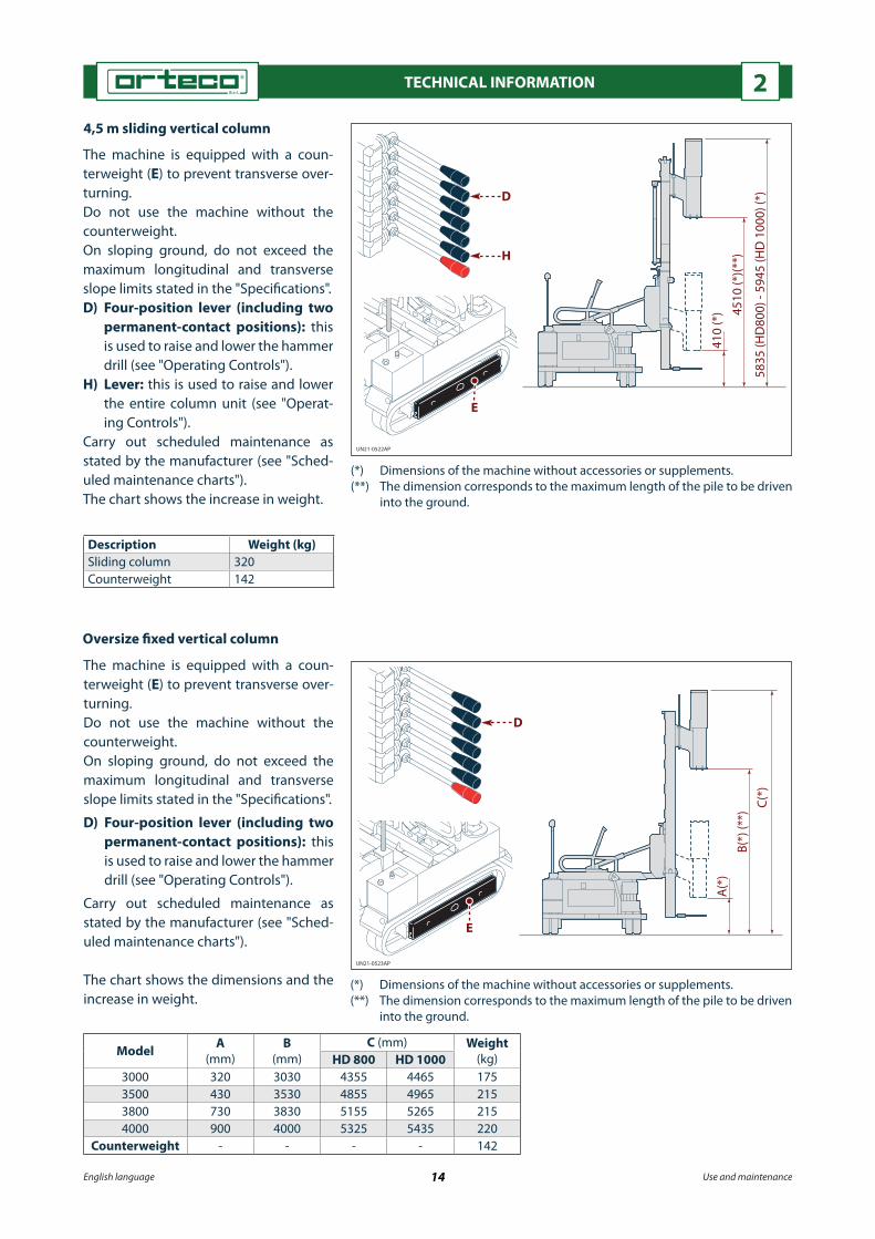
4,5 m sliding vertical column
The machine is equipped with a coun-terweight (E) to prevent transverse over-turning.Do not use the machine without the counterweight.On sloping ground, do not exceed the maximum longitudinal and transverse slope limits stated in the "Speci�cations".D) Four-position lever (including two
permanent-contact positions): this is used to raise and lower the hammer drill (see "Operating Controls").
H) Lever: this is used to raise and lower the entire column unit (see "Operat-ing Controls").
Carry out scheduled maintenance as stated by the manufacturer (see "Sched-uled maintenance charts").The chart shows the increase in weight.
(*) Dimensions of the machine without accessories or supplements.(**) The dimension corresponds to the maximum length of the pile to be driven
into the ground.
Description Weight (kg)Sliding column 320Counterweight 142
Oversize �xed vertical column
The machine is equipped with a coun-terweight (E) to prevent transverse over-turning.Do not use the machine without the counterweight.On sloping ground, do not exceed the maximum longitudinal and transverse slope limits stated in the "Speci�cations".
D) Four-position lever (including two permanent-contact positions): this is used to raise and lower the hammer drill (see "Operating Controls").
Carry out scheduled maintenance as stated by the manufacturer (see "Sched-uled maintenance charts").
The chart shows the dimensions and the increase in weight.
(*) Dimensions of the machine without accessories or supplements.(**) The dimension corresponds to the maximum length of the pile to be driven
into the ground.
Model A (mm)
B (mm)
C (mm) Weight (kg)HD 800 HD 1000
3000 320 3030 4355 4465 1753500 430 3530 4855 4965 2153800 730 3830 5155 5265 2154000 900 4000 5325 5435 220
Counterweight - - - - 142

UN21-0524AP
10°
5°
0°
English language 15 Use and maintenance
TECHNICAL INFORMATION 2
Macro tilt
The pile driver is tilted via a manually operated cylinder (see "Procedure for use of the macro tilt").
The chart shows the increase in weight.
Description Weight (kg)
Macro tilt 35

UN21-0525AP
B
E
C
D
F
A
English language 16 Use and maintenance
TECHNICAL INFORMATION 2Accessories
A) Clamp: used to extract piles from the ground (piles for guard-rails, piles for photovoltaic systems, etc). For assembly, use and maintenance of the clamp, see "Metal pile extrac-tion procedure".
B) Corer: to make circular holes with a diamond cup-shaped tool in hard and compact areas (road surfaces in cement, asphalt, etc.).
For assembly, use and maintenance of the core borer, see "Core boring procedure".C) Boring device: to make circular holes on hard and compact surfaces (cement, rock) us-
ing a tool with a combined rotation and percussion action. For assembly, use and maintenance of the drilling machine, see "Drilling procedure with
the drilling machine".D) Drill: to drill holes in ground containing a small quantity of rock fragments (gravel,
crushed stone, etc.). For assembly, use and maintenance of the drill, see "Drilling procedure with the drill".E) Electrical power generator: this is activated by the machine’s hydraulic system and
supplies electricity to the electric tools (drill, screwdriver, etc.). For use and maintenance of the electric generator, see "Activating the electric genera-
tor."F) Blade raiser: this is used to position the segments of guardrail (already bolted and laid
on the ground) against the pile. For assembly, use and maintenance of the blade raiser, see "Guardrail lifting proce-
dure".
Pos. Weight (kg)
A 49
B 38
C 90 (RP 200)148 (RP 500)
D 52 (T2)104 (T3)
E 40
F 320

UN21-0526AP
OFF
F
D
E
LB
C
G
A
H
English language 17 Use and maintenance
TECHNICAL INFORMATION 2
Supplements
A) Supplementary air �lter: to �lter the air taken in by the motor in particularly dusty work conditions.
B) “Laser” device: to automatically stop the driving of a pile or the execution of a hole at the required depth.
For its use see “Adjusting the ‘laser device’ that stops the hammer’s down stroke”.C) Column verticality automatic device: to automatically place the column in vertical
position, independently from the gradient of the ground.D) Compressed air circuit: to supply to the boring device the air necessary for the percus-
sion action and to clean the hole.E) Lights: to illuminate the work area in case of low visibility or at night (see “Working at
night or with low visibility”).F) Tow hook: to tow equipment on wheels (compressor, trolley, etc.). The maximum load
that can be towed is shown on the plate on the tow hook.G) Radio control: this is used to remotely control the machine using radio waves.H) System for measuring the distance between the piles: this signals the previously calcu-
lated driving distance between the last pile driven in and the following one.L) Magnet: this is used to lift particularly large ferromagnetic piles into the driving posi-
tion.

English language 18 Use and maintenance
SAFETY INFORMATION 3General safety warnings
Failure to comply with some simple safety and prudence rules is the cause of most accidents and injuries at work.In most cases, accidents can be avoided by foreseeing the possible causes and conse-quently acting with the necessary care and caution.Every worker in�uences, with his /her behaviour, the risks related to the activity to be carried out, therefore a careful and prudent worker is the best guarantee against accidents.Before using the machine, the operator and other workers must carefully read and understand the instructions contained in the manual supplied and those directly ap-plied to the machine.It is important to pay attention to the meaning of the symbols on the labels applied; their shape and colour are very important for safety purposes. All labels must be leg-ible and the information they contain must be respected.When the machine is in use, the operator and the people directly involved in the oper-ations must wear accident prevention equipment; for this purpose contact the safety manager.On no account must you tamper with, eliminate or by-pass the safety devices as this could seriously put at risk the health of people.Never start or use the machine in poorly ventilated areas. If necessary, adopt all nec-essary precautions to prevent build-ups of machine exhaust gas.
Use and operation safety precautions
The operator must know well the performance and weight of the machine in relation to the type of ground (�at, compact, rough, sloping) in order to always maintain a safe distance when working near open excavations, slopes , verges and overhanging rocks.Use the machine only if you are in good physical and mental condition.Check that the routs at the site are suitable and that the work areas are suitable for the passage and stability of the machine. Ask for the the expert operators’ assistance for operations in tight spaces and with poor visibility.In the case of operations near particularly high mounds of land make sure that the excavation walls are correctly buttressed to avoid landslides caused by the vibrations transferred from the machine to the ground.At the end of the shift or day do not park the machine inside banks or waterways.Mark-o� the work area with appropriate signs and forbid access to anyone not in-volved in the operations. The operator must make sure said prohibition is respected even by suspending work.Do not use the hammer to lift people, pull or lift loads.Do not use the machine during storms.Make sure there are no buried pipelines or cables which could interfere with the pile driving operation (gas or water pipes, electric cables).
English language 19 Use and maintenance
SAFETY INFORMATION 3Keep a safe distance from the lines of public utilities. In case of work near buried pipe-lines or cables (gas or water pipes, electric cables) contact the provider requesting assistance to search for the lines and eventually disable them.
Do not �ll the fuel tank when smoking, when the engine is on or hot or near naked �ames.
Handling and transport safety precautions
Lifting and handling operations must be carried out following the information on the machine and in the manufacturer's use manual.
Loading, unloading, handling and lifting operations must be carried out by quali�ed and authorised personnel that has received speci�c training.
Before transferring the machine check that the machine and its components are an-chored to the means of transport to avoid uncontrolled movements and check that the pro�le is within the foreseen overall dimensions. If necessary apply the necessary markings.
Safety instructions for adjustment and maintenance
Maintenance is of primary importance for the e�ciency and reliability of the machine and is one of the most important safety elements.
Maintenance schedule operations must be carried out at the set intervals and in the manner foreseen by the manufacturer.
For maintenance operations that require special equipment and/or specialised knowl-edge contact the authorised assistance centres.
Before carrying out any maintenance or adjustment operation lower the hammer to the ground, switch o� the engine and remove the ignition key.
Servicing of hydraulic components must be carried out only with the system depres-surised.
When searching for oil leaks from hydraulic components, all the necessary measures must be taken to avoid injuries (perforations) caused by the pressurised oil.
Worn parts must be replaced with original spare parts.
Before working on the engine or near it, make sure it is cold.
Dispose of polluting material in compliance with the regulations in force in the coun-try of use; do not �y tip it.
Keep the engine, battery, fuel tank and hydraulic oil tank areas clean to avoid the risk of �re caused by the build-up of residues.
Before any adjustment operation activate all safety devices foreseen and assess whether personnel working nearby must be informed of the operation.
At the end of the operations, before starting the machine, check that there are no tools, cloths or other material near the moving parts or in risk areas.

English language 20 Use and maintenance
SAFETY INFORMATION 3
Environmental protection precautions
Improper disposal of waste can cause environmental and ecological damage.
Potentially polluting waste installed on the machine (fuel, oil, coolant, �lters and bat-teries) must be separated and disposed of in di�erent ways, according to the di�erent composition of the products, in compliance with the laws in force.
Keep the exhaust gases within the minimum values in order to limit the emissions into the atmosphere.
Correctly dispose of waste from electrical and electronic equipment because it may contain substances that are potentially harmful to the environment and to people’s health.
Fire-prevention and �rst aid measures
First aid measures
In the event of an accident, provide medical assistance as envisaged by legislation and standards in force in the country where the machine is in use.
In the event of contact with fuel or hydraulic oil, refer to the “Safety and environmen-tal data sheets for hydraulic oil” or the “Safety and environmental data sheets for fuel”.
Fire prevention measures
In the event of an accident, follow the procedures envisaged by legislation or stand-ards in force in the country where the machine is in use.
Operators must take all precautionary measures to prevent �res occurring and to limit the consequences in the event a �re does occur.
Do not smoke or use open �ames during refuelling and clean up any fuel and hydrau-lic �uid leaks on the pile driver immediately.

English language 21 Use and maintenance
HANDLING AND TRANSPORTATION 4
Advice for handling and transportation
Before starting any operation, the work area must be organised to safely carry out lifting and handling operations.
During lifting and handling operations anyone not involved must keep a safe dis-tance.
Hooks and ropes in good condition suitable for the load to be lifted must be used for lifting operations.
Transportation by rail, sea or air must be carried out in compliance with the regula-tions and laws in force.
Transport on public roads must comply with the local laws in force.
If necessary, when loading and unloading from the truck use ramps which are in good condition and o�er the appropriate load-bearing capacity.
Transportation procedure
The machine, depending also on the destination, can be delivered using di�erent transport means (road, rail, sea and air).
The machine is delivered completely assembled or divided in two parts (tracked truck and pile driver) to make it easier to transport, with the disassembled components in a wooden crate. The parcels can be loaded onto a means of transport directly or in suitable containers if shipped by sea or air or to far-o� destinations.
The manufacturer has foreseen anchorage points to guarantee stability of the assembled or split machine on the transport means.

UN21-0464BO
min
. 400
0 m
m
A
UN21-0465BO
A
English language 22 Use and maintenance
HANDLING AND TRANSPORTATION 4
Lifting the machine
WARNING
The assembled machine must only be lifted when the pile driver is in resting position using suitable equipment (lifting beam) to avoid damaging it.Hooks and ropes in good condition suitable for the load to be lifted must be used for lifting operations.
Proceed as outlined below.1) Check the weight of the machine to be lifted in the “Technical speci�cations” chapter to
make sure the lifting means is suitable.2) Fix the lifting ropes to the eyebolts marked (A) indicated by a special sign.
The illustration shows the harnessing points and lifting procedure.
Lifting the truck
Proceed as outlined below.1) Check the weight of the truck to be lifted in the “Technical information” chapter to make
sure the lifting means is suitable.2) Fix the lifting ropes to the eyebolts marked (A) indicated by a special sign.
The illustration shows the harnessing points and lifting procedure.
UN21-0466BO
A
A
A
B
English language 23 Use and maintenance
HANDLING AND TRANSPORTATION 4
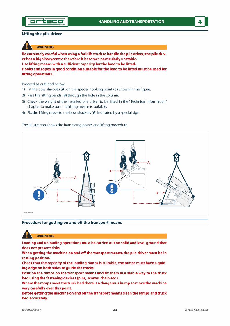
Lifting the pile driver
WARNING
Be extremely careful when using a forklift truck to handle the pile driver; the pile driv-er has a high barycentre therefore it becomes particularly unstable.Use lifting means with a su�cient capacity for the load to be lifted.Hooks and ropes in good condition suitable for the load to be lifted must be used for lifting operations.
Proceed as outlined below.1) Fit the bow shackles (A) on the special hooking points as shown in the �gure.
2) Pass the lifting bands (B) through the hole in the column.
3) Check the weight of the installed pile driver to be lifted in the “Technical information” chapter to make sure the lifting means is suitable.
4) Fix the lifting ropes to the bow shackles (A) indicated by a special sign.
The illustration shows the harnessing points and lifting procedure.
Procedure for getting on and o� the transport means
WARNING
Loading and unloading operations must be carried out on solid and level ground that does not present risks.When getting the machine on and o� the transport means, the pile driver must be in resting position.Check that the capacity of the loading ramps is suitable; the ramps must have a guid-ing edge on both sides to guide the tracks.Position the ramps on the transport means and �x them in a stable way to the truck bed using the fastening devices (pins, screws, chain etc.).Where the ramps meet the truck bed there is a dangerous bump so move the machine very carefully over this point.Before getting the machine on and o� the transport means clean the ramps and truck bed accurately.

UN21-0467BO
A AMax 14° (25%)
D D
B C
E
English language 24 Use and maintenance
HANDLING AND TRANSPORTATION 4
Pull the parking brake of the transport means and position the chocks (A) against the wheels.Move on and o� the transport means with the controls facing the truck bed as shown in the �gure to reduce to a minimum the risk of accidents should the machine tip over.
To get the machine on proceed as outlined below.
1) Unscrew the wing screw (B) and remove the rotary lamp to avoid damaging it during transport.
Use the cap (C) to prevent the rotary lamp support from getting dirty.
2) Start the machine (see “Starting the engine”).
3) Position the machine centrally to the ramps and if necessary adjust the width of the ramps so that the machine weight is evenly distributed.
4) Move up onto the transport means with minimum forward speed.
5) Switch o� the engine and remove the ignition key.
6) Place the chocks (D) against the tracks.7) Anchor the machine to the transport means by passing chains or ropes through the lift-
ing eyebolts (E), indicated by the special sign.

UN21-0468BO
A AMax 14° (25%)
D D
B C
E
English language 25 Use and maintenance
HANDLING AND TRANSPORTATION 4
To get the machine o� proceed as outlined below.1) Remove the ropes that anchor the machine to the transport means from the eyebolts
(E), indicated by the special sign.2) Remove the chocks (D) from the tracks.3) Start the machine (see “Starting the engine”).4) Position the machine centrally to the ramps and if necessary adjust the width of the
ramps so that the machine weight is evenly distributed.5) Move o� the transport means at minimum forward speed.
6) Remove cap (C) from the rotary lamp support.
7) Mount the rotary lamp on the support and tighten the wing screw (B) to lock it in place.
Assembly of pile driver on the crawler
The machine delivered in di�erent parts (crawler and pile driver), must be assembled by duly trained personnel in an authorised service centre.
The authorised service centre has all the information about the safety warnings and the procedures to follow in order to ensure safe and proper assembly.
Do not carry out any of the activities required if the assembly information is missing and you are not suitably trained to perform them properly and safely.
The sta� member must be authorised to perform the required activities.
UN21-0469BO
10 - 15 mm
A B C D
English language 26 Use and maintenance
ADJUSTMENT INFORMATION 5
Safety advice for the adjustments
To protect the people involved, the adjustment operations must be carried out with all safety devices activated and unauthorised people must not be allowed to access the area of operation which must be appropriately marked.
Prima di riavviare la macchina controllare che non siano rimasti attrezzi, stracci o al-Before starting the machine, check that there are no tools, cloths or other material near the moving parts or in risk areas.
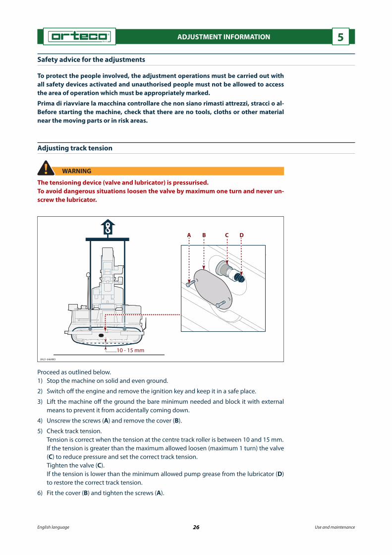
Adjusting track tension
WARNING
The tensioning device (valve and lubricator) is pressurised.To avoid dangerous situations loosen the valve by maximum one turn and never un-screw the lubricator.
Proceed as outlined below.1) Stop the machine on solid and even ground.
2) Switch o� the engine and remove the ignition key and keep it in a safe place.
3) Lift the machine o� the ground the bare minimum needed and block it with external means to prevent it from accidentally coming down.
4) Unscrew the screws (A) and remove the cover (B).
5) Check track tension. Tension is correct when the tension at the centre track roller is between 10 and 15 mm. If the tension is greater than the maximum allowed loosen (maximum 1 turn) the valve
(C) to reduce pressure and set the correct track tension. Tighten the valve (C). If the tension is lower than the minimum allowed pump grease from the lubricator (D)
to restore the correct track tension.
6) Fit the cover (B) and tighten the screws (A).

UN21-0527AP
OFFA
A
B
C
1
D
E0 E
F
F1
English language 27 Use and maintenance
ADJUSTMENT INFORMATION 5
Adjusting of “PROXIMITY device” that stops the hammer’s down stroke
The “PROXIMITY device” that stops automatically the hammer’s down stroke is used to drive piles into the ground or make holes in the ground at the same depth dependending on the type of ground.
Adjusting the pile driving depth
Proceed as outlined below.1) Rotate the selector switch (D) to “OFF” position.
2) Drive a pile into the ground at the required depth (see “Pile driving procedure”).
3) Stop the percussion and rest the hammer on the pile head.
4) Loosen the screws (A).
5) Adjust the device (B) at the centre line of the proximity sensor (C) as shown in the �g-ure.
6) Tighten the screws (A).
7) Turn the selector (D) to the “PROXIMITY” position (1) to activate the device.
8) Drive another pile into the ground until the stop device automatically interrupts the pile driving operation.
9) Move lever (E) to "E0" position.
10) Move the lever (F) to position "F1" to lift the hammer from the pile and measure its height.
11) Check the correct pile driving depth. If the driving depth is not correct repeat the adjustment to correct the error.- Turn the selector (D) to the “OFF” position to deactivate the device.

UN21-0527AP
OFFA
A
B
C
1
D
E0 E
F
F1
English language 28 Use and maintenance
ADJUSTMENT INFORMATION 5
Adjusting the hole depth
(For holes made with the boring device and drill)
Proceed as outlined below.1) Rotate the selector switch (D) to “OFF” position.
2) Make the hole at the depth required (see the “Procedure to make holes using the bor-ing device” or the “Procedure to make holes using the drill”).
3) Move the lever (E) to position "E0" to stop the tool rotation. Keep the tool in contact with the ground.
4) Loosen the screws (A).
5) Adjust the device (B) at the centre line of the proximity sensor (C) as shown in the �g-ure.
6) Tighten the screws (A).
7) Turn the selector (D) to the “PROXIMITY” position (1) to activate the device.
8) Make another hole until the stop device automatically interrupts the progress of the tool.
9) Move the lever (E) to position "E0" to stop the tool rotation.
10) Move the lever (F) to position "F1" to remove the tool from the hole.
11) Check the correct depth of the hole. If the depth of the hole is not correct repeat the adjustment to correct the error.- Turn the selector (D) to the “OFF” position to deactivate the device.

UN21-0528AP
G2
OFF
C
B
1
F
GA
F0
DE
D
English language 29 Use and maintenance
ADJUSTMENT INFORMATION 5
Adjusting the “laser device” that stops the hammer’s down stroke
The “laser device” is used to drive piles into the ground or make holes in the ground at the same depth compared to a �xed reference (emitter) and automatically stops the descent of the percussion hammer when the preset depth is reached (pile driving or hole depth), independently from the type of ground.
The same pile driving and hole depth is obtained by using a laser emitter that acts as �xed reference point and a receiver �tted on the pile driver.
Adjusting the pile driving depth
Proceed as outlined below.1) Rotate the selector switch (A) to “OFF” position.2) Drive the pile into the ground at the required depth.3) Stop the percussion and rest the hammer on the pile head.4) Activate the emitter of the “laser device”.5) Turn the selector (A) to the “laser” position (1) to activate the device.6) Position the laser emitter (B) at a distance of at least 100 - 150 m from the pile-driver.7) Adjust the laser emitter (B) at a height from the ground similar to that of the receiver
and is such a way that there are no obstacles between the emitter and the receiver (C).
8) Loosen the locking levers (D).9) Slide the receiver (C) along the pipe to intercept the laser ray until the green lights (E)
light up.10) Tighten the levers (D) to lock the receiver in the required position.11) Drive another pile into the ground until the “laser device” automatically interrupts the
pile driving operation.12) Move lever (F) to "F0" position.13) Move the lever (G) to position "G2" to lift the percussion hammer.14) Check the correct pile driving depth. If the driving depth is not correct repeat the adjustment to correct the error.- Turn the selector (A) to the “OFF” position to deactivate the device.

UN21-0528AP
G2
OFF
C
B
1
F
GA
F0
DE
D
English language 30 Use and maintenance
ADJUSTMENT INFORMATION 5
Adjusting the hole depth
(For holes made with the boring device and drill)
Proceed as outlined below.1) Rotate the selector switch (A) to “OFF” position.2) Make the hole at the depth required (see the “Procedure to make holes using the bor-
ing device” or the “Procedure to make holes using the drill”).3) Move the lever (F) to position "F0" to stop the tool rotation. Keep the tool in contact with the bottom of the hole.4) Activate the emitter of the “laser device”.5) Turn the selector (A) to the “laser” position (1) to activate the device.6) Position the laser emitter (B) at a maximum distance of 100 - 150 m from the pile-
driver.7) Adjust the laser emitter (B) at a height from the ground similar to that of the receiver
and is such a way that there are no obstacles between the emitter and the receiver (C).
8) Loosen the locking levers (D).9) Slide the receiver (C) along the pipe to intercept the laser ray until the green lights (E)
light up.10) Tighten the levers (D) to lock the receiver in the required position.11) Make another hole until the “laser device” automatically interrupts the progress of the
tool.12) Move the lever (F) to position "F0" to stop the tool rotation.13) Move the lever (G) to position (G2) to remove the tool from the hole.14) Check the correct depth of the hole. If the depth of the hole is not correct repeat the adjustment to correct the error.- Turn the selector (A) to the “OFF” position to deactivate the device.

English language 31 Use and maintenance
INFORMATION FOR USE 6
Safety advice concerning use
Do not allow unauthorised persons to work on the machine.
The operator must be appropriately trained and informed on the use of the machine; upon �rst use of the machine, the operator must perform a range of practice manoeu-vres to acquire familiarity with the controls and main functions.
Machines in the additional extension version must be equipped with a counter-weight.
Always check the work area for any risks.
Take particular care when working on sloping ground, bumpy areas, slopes and high mounds of land, gorges, ditches, �lled excavations and ridges, rough ground, wet or muddy ground.
On sloping ground, move and operate the machine only within the limits foreseen by the manufacturer (see “Technical characteristics”).
Keep away from the digging area and do not drive near the edges unless they have been tested for stability.
Before use check the e�ciency of the controls, braking and parking devices, rotary lamp and buzzer.
Do not stop or pass under the percussion hammer.
On public roads the work area must be adequately marked with signs.
Description of the controls
NOTICE
The machine may be equipped with proportional control distributors (either me-chanical or electric).
For identi�cation purposes, the controls have been divided as described below.- Dashboard controls (base version).- Controls to run the machine.- Operation controls.

UN21-0473BO
US
A
D E F G H LM
P
BN QC1 C2 C
T
R
English language 32 Use and maintenance
INFORMATION FOR USE 6Dashboard controls (base version)
The controls of any accessory installed on the machine are described in the use procedures of each single accessory.
A) Disconnecting switch to isolate the batteries: to disconnect and connect the battery to the electrical system.
B) Ignition switch: to switch on the engine.
C) Multifunction signalling instrument: this shows the engine rpm (C1) and the number of hours of operation (C2).
D) Signal light (red): this indicates the state of operation of the alternator; when the light is on, it means the alternator is not charging the battery.
E) Signal light (red): this shows there is insu�cient engine oil pressure.
F) Signal light (red): this shows that the engine air �lter is clogged.
G) Signal light (red): this shows the engine is overheating.
H) Signal light (orange): low fuel warning light.
L) Signal light (red): this shows that the delivery �lter of the hydraulic system is clogged.
M) Area without control device.
N) Buzzer.
1) This warns the operator, with a continuous signal, that the oil pressure is low. The motor stops automatically and lights (D) and (E) come on.
2) This warns the operator, with a continuous signal, that the emergency button has been activated. The motor stops automatically and lights (D) and (E) come on.
3) This warns the operator, with an intermittent signal, that the engine is overheating. Sig-nal light (G) comes on. Switch o� the engine immediately and remove the cause of the overheating.
P) Area without control device.

UN21-0474BO
0
2
1
II
II
I
B
A
Dx
I
Sx
English language 33 Use and maintenance
INFORMATION FOR USE 6Q) Area without control device.
R) Accelerator lever: to change the engine rpm.
S) Emergency stop button: to stop the machine in the case of impending risk.
T) Signal light (orange): this shows that the pre-heating glow plugs have been activated (for diesel engines).
U) Valve: this is used to open and close the �ow of fuel from the tank to the engine.
Controls to run the machine
A) Lever: to activate the left track (Sx). Move the lever to position (1) to move the track in direction (I). Move the lever to position (2) to move the track in direction (II). When the lever is released, it returns to neutral position (0). When the lever is in neutral position, the movements of the left track are disabled.
B) Lever: to activate the right track (Dx). Move the lever to position (1) to move the track in direction (I). Move the lever to position (2) to move the track in direction (II). When the lever is released, it returns to neutral position (0). When the lever is in neutral position, the movements of the right track are disabled.

UN21-0529AP
01
2
D3
D2
D1
D0
L0
L2
L1
LHGFE
CD
A
B
English language 34 Use and maintenance
INFORMATION FOR USE 6
C) Lever: to tilt the column lengthways in relation to the machine.- Position (1): this activates column tilt to the left.- Position (2): this activates column tilt to the right.- When the lever is released, it returns to neutral position (0).- Neutral position (0): this deactivates column tilting.
D) Four-position lever (two stable “D0" - "D3”): to lift and lower the percussion ham-mer.
- Position “D1”: to activate the rapid lowering of the percussion hammer.- Position “D3”: to activate the slow (�oating) lowering of the percussion hammer.- Position “D2”: to activate the lifting of the percussion hammer.- Neutral position “D0”: this deactivates the up and down movements of the percussion
hammer.
NOTICE
If equipped with an electric module, the proportional distributor has no permanent contact position (D3) when actuated manually, which means the operator will have to hold the lever in position during work.
E) Lever: to shift the column transversally.- Position (1): this activates column retraction. - Position (2): this activates column extension.- When the lever is released, it returns to neutral position (0).- Neutral position (0): this disables transverse column shifting.
F) Lever: to tilt the column transversally.- Position (1): this activates column tilt to the left.- Position (2): this activates column tilt to the right.- When the lever is released, it returns to neutral position (0).- Neutral position (0): this disables transverse column tilting.
Operation controls
A) Pressure gauge: this shows the pressure of the pile driver’s hydraulic circuit.
B) Switch: to switch the hydraulic power supply to the hammer or accessory.

English language 35 Use and maintenance
INFORMATION FOR USE 6G) Lever: to shift the column lengthways.- Position (1): this activates column shifting to the left.- Position (2): this activates column shifting to the right.- When the lever is released, it returns to neutral position (0).- Neutral position (0): this disables longitudinal column travel.
H) Lever: to activate the outrigger jack.- Position (1): this activates cylinder extension onto the ground.- Position (2): this activates cylinder retraction from the ground.- When the lever is released, it returns to neutral position (0).- Neutral position (0): this deactivates outrigger cylinder movements.
NOTICE
In the version with the 4,5 m sliding vertical column, the lever controls the vertical movement of the entire column.
L) Lever with two stable positions (red - “L0” - “L1”): to activate and disable the percus-sion hammer.
The lever is also used to activate certain accessories such as the corer, boring device, drill, etc. (see the procedure for the use of the accessory installed on the machine).
- Position “L1”: to activate the percussion hammer.- Position “L0”: to stop the percussion hammer.- Position “L2”: if featured, it activates the opposite rotation of certain accessories.
NOTICE
The manually operated proportional distributor is equipped with a clutched lever. This lever remains in the position in which it was left by the operator. If equipped with an electric module, the proportional distributor has no permanent contact position (D3) when actuated manually, which means the operator will have to hold the lever in position during work.
Use in cold environmental conditions
At temperatures below 0 °C, the procedure described below must be implemented.
- Only use hydraulic oil and lubricants suitable for the working temperature.
- Check battery e�ciency.
- Activate the controls of the hydraulic jacks to heat the oil to a temperature of 22 - 25 °C.
- Activate the percussion at a minimum stroke frequency for at least 5 minutes to heat the percussion hammer.

UN21-0476BO
T
D E L Q
BCB1B2
S
AR
English language 36 Use and maintenance
INFORMATION FOR USE 6
Starting the engine
NOTICE
The electric starting motor must not be used continuously for more than 10 seconds.When trying to start the machine wait one minute between each attempt to allow the electric motor to cool.At each start-up check that the buzzer (Q) is in good working order (continuous sound signal).
To start the machine at temperatures below 0 °C proceed as described.
1) Check that the emergency stop button (S) is o�.2) Turn the battery isolation switch (A) to activate the dashboard and the electrical sys-
tem.3) Check that the fuel valve (T) is open. 4) Position the accelerator lever (R) about half way.5) Turn the ignition key (B) by one click (position “I”).6) The signal lights (D and E) switch on and the buzzer (Q) sounds.7) Turn the ignition key (B) one more click to position "B1" to start the engine.8) When the motor is on, the signal lights (D and E) switch o� and the buzzer (Q) stops.
To start the machine at temperatures above 0 °C proceed as described.
1) Check that the emergency stop button (S) is o�.2) Turn the battery isolation switch (A) to activate the dashboard and the electrical sys-
tem.3) Position the accelerator lever (R) about half way.4) At temperatures below zero if the glow plugs supplement is featured turn the key to-
wards the symbol "B2"; at the same time signal light (L) comes on.

UN21-0477BO
1
3
2
4
English language 37 Use and maintenance
INFORMATION FOR USE 6
Keep the key in that position for the heating time necessary (usually 1 minute). Release the key; the signal light will switch o�.
5) Turn the ignition key (B) by one click (position “I”).
6) The signal lights (D and E) switch on and the buzzer (Q) sounds.
7) Turn the ignition key (B) one more click to position "B1" to start the engine.
8) When the motor is on, the signal lights (D and E) switch o� and the buzzer (Q) stops.
Starting the engine with the auxiliary battery
NOTICE
Do not cause sparks or use naked �ames near the batteries.Avoid direct contact with the battery liquid.Use cables with an adequate section and isolated terminals.
If the battery is �at, the engine can be started with another battery (auxiliary) with a nomi-nal voltage and capacity identical to the �at battery.
Proceed as outlined below.
1) Connect the cables in the order shown in the �gure.
2) Start the machine (see “Starting the engine”).
3) Disconnect the cables in reverse order.

UN21-0478BO
II
III
IV
I
VI
V
E
0
2
1
C
A
B
English language 38 Use and maintenance
INFORMATION FOR USE 6
Shifting procedure
WARNING Machines in the additional extension version must be equipped with a counter-weight. The operator must control the machine from the ground.Turn (both forwards and backwards) gradually to reduce the wear of the tracks.The controls must be operated gently and smoothly to avoid sudden movements of the machine which could injure the operator or people nearby.Unauthorised persons are prohibited from standing or moving in the work area.
For short journeys (between a driven pile and the next one to be driven) keep the pile-driver in working position and control the machine from the position (E) foreseen for the operator.
For transfers at the work site put the pile-driver in resting position (C) and control the ma-chine from the position (E) foreseen for the operator.
Proceed as outlined below.1) Start the engine (see “Starting the engine”).2) Move levers (A) and (B) at the same time towards the position (1) to move the machine
forwards in the direction (I).3) Move levers (A) and (B) at the same time towards the position (2) to move the machine
forwards in the direction (II).4) Move the lever (A) further than the lever (B) towards the position (1) to gradually turn in
the direction (IV).5) Move the lever (A) further than the lever (B) towards the position (2) to gradually turn in
the direction (VI).6) Move the lever (B) further than the lever (A) towards the position (1) to gradually turn in
the direction (III).7) Move the lever (B) further than the lever (A) towards the position (2) to gradually turn in
the direction (V).

UN21-0479BO
II
III
IV
I
VI
V
E
C
DA
B
0
2
1
English language 39 Use and maintenance
INFORMATION FOR USE 6
E) Control position foreseen for the operator
Shifting on slopes procedure
WARNING
Travel only on slopes within the maximum slope limits foreseen by the manufacturer (see “Technical characteristics”).On sloping ground keep the percussion hammer completely lowered to increase ma-chine stability.In the case of long stretches on sloping ground keep the pile driver in resting position (C) to increase machine stability. Avoid moving transversally to the slope; move verti-cally (up-down and vice versa).The gradient that can be tackled depends on various factors: the type of ground (soft, slippery, wet or markedly uneven), the speed and visibility.When working on sloping ground the operator’s experience and good sense prevail over any rule.
Proceed as outlined below.1) Start the engine (see “Starting the engine”).
WARNING
On sloping ground travel at minimum speed to prevent the risk of the machine over-turning.
2) Move levers (A) and (B) at the same time towards the position (1) to move the machine forwards in the direction (I).
3) Move levers (A) and (B) at the same time towards the position (2) to move the machine forwards in the direction (II).
4) Move the lever (A) further than the lever (B) towards the position (1) to gradually turn in the direction (IV).
5) Move the lever (A) further than the lever (B) towards the position (2) to gradually turn in the direction (VI).
6) Move the lever (B) further than the lever (A) towards the position (1) to gradually turn in the direction (III).
7) Move the lever (B) further than the lever (A) towards the position (2) to gradually turn in the direction (V).

UN21-0530AP
R0
B3 PB
AU
W
R
E
C
D
G
N
T
M
Q F
L
H
S
X
Y
English language 40 Use and maintenance
INFORMATION FOR USE 6
Y) Control position foreseen for the operator
Pile driving procedure
WARNING
Only drive the pile into sloping ground within the limits foreseen by the manufac-turer.On sloping ground position the machine with the pile driver as close as possible to the truck to reduce the risk of tipping over.
The operator must be positioned as shown in the �gure.When driving the pile into the ground the percussion hammer must be manually placed in a perfectly vertical position (see "Operation controls”) or automatically (see “Using the verticality system”).To manually place the column in a perfectly vertical position use the level gauge (Q).Check the need to replace, according to the type of pile to be driven, the stroke plate (H) and the matrix (T) (see “Replacing the stroke plate”).
Proceed as outlined below.1) Move the lever (A) to lift the column vertically compared to the ground.2) Move the lever (B) to lift the percussion hammer.3) Tighten the safety lock pin (S) and slowly rest the hammer on the pin.4) Remove the peg (C) and the pin (D).
English language 41 Use and maintenance
INFORMATION FOR USE 65) Support the guide (F), release it from the pin (G) and rotate it downwards.6) Slide in the pin (D) and the peg (C).7) Lock the guide with the bolts (E).8) Fit the guide plate (L) and lock it with the pins (M) and the safety split pins (N).9) Install the matrix (T) on the guide plate (L).10) Lift the hammer slightly and unscrew the safety lock pin (S).11) Move the levers (X) to shift the machine to the pile extraction point.12) Move the lever (P) and the lever (A) to position the column vertically. Check the verticality using the level gauge (Q).13) Move the lever (U) and the lever (W) to position the percussion hammer right on the
driving point. To make it easier, the centre of the matrix can be used as reference (T).14) Insert the pile between the stroke plate (H) and matrix (T).
WARNING
Take care when the hammer is lowered because there is the risk of crushing hands between the pile head and the stroke plate.Remain at the side of the percussion hammer to avoid being hit if the percussion ham-mer comes down suddenly.
15) Move the lever (B) to lower the hammer onto the pile until the head of the pile is inside the grooved pro�le of the stroke plate and then move it to the �oating position “B3”.
NOTICE
Make sure that the automatic verticality system is disabled before activating the per-cussion hammer, to avoid damaging the device.
16) Move the lever (R) to activate the percussion hammer.
NOTICE
When working on extremely hard ground, it is important not to use a pneumatic drill for more than 30 seconds at a time. After this limit, stop for at least 15 seconds before resuming drilling.If the pile does not go into the ground, do not attempt to force it; there is probably an obstruction preventing it from being driven in fully.
NOTICE
To automatically stop the pile driving operation at the required depth see the “Ad-justing of PROXIMITY device that stops the hammer’s down stroke” section.If the machine is �tted with the laser device see the “Adjusting the laser device that stops the hammer’s down stroke” section.
17) Once the required depth has been reached move the lever (R) to position "R0" to stop the percussion or activate the automatic stop devices (Proximity and laser).
18) Move the lever (B) to lift the percussion hammer.19) Move the machine to the point where the next pile is to be driven in.
WARNING
The operator and other workers must remain at a safe distance from the pile during the manoeuvres to release it, in order to avoid getting knocked over if the pile sud-denly comes unhooked.
If the pile gets blocked in the stroke plate proceed as described.1) Move the levers (P, U, A, W) and make small movements to unblock the pile from the
stroke plate.2) When the pile is free from the stroke plate, move the lever (B) to lift the percussion
hammer.

UN21-0531AP
AB
C
D G
F
H
E
L
English language 42 Use and maintenance
INFORMATION FOR USE 6
Procedure for use of the macro tilt
Proceed as outlined below.1) Position the jack (E) on the support base as shown in the �gure.
2) Position the jack shaft in the support seat (G) and apply light pressure.
3) Remove the peg (C) and the pin (D).
4) Remove the peg (A) and the pin (B).
5) Move lever (F) to tilt the pile-driver base to align the holes corresponding to the neces-sary tilt to drive the pile.
6) Slide in the pins (B and D) in the holes and the pegs (A and C) to lock the base in the required position.
7) Insert the lever (F) in the pin (H).
8) Turn the lever (F) to lower the jack shaft.
9) Remove the jack (E).
To tilt the base in the opposite direction repeat the same operations on the other side of the base.
On steeply sloping ground tilt the pile-driver to place the column in vertical position.To place the column in a vertical position use the level gauge (L).
The pile-driver can be longitudinally tilted from the right or left side.

UN21-0532AP
Q1
Q
H
F
G
NT
U
N2
M
L
S
Q0
W Y
A
BP
C
R
E
D V
English language 43 Use and maintenance
INFORMATION FOR USE 6
Y) Control position foreseen for the operator
Gripper for metal pile extraction - instructions for assembly, use, and maintenance
The extraction gripper is designed to extract metal piles from soil and from bituminous concrete. To extract metal piles the extraction clamp must be �tted on the hammer.Remove the pile-guide if present.In the assembly phase, the operator must stand at the side of the percussion hammer (see �gure).
WARNING
Fit the clamp with the machine parked on �at and stable ground, the engine o� and the percussion hammer at minimum distance from the ground. Do not use the grip-per if it is damaged or there is a malfunction in the grip lock system.
Fitting the pile extraction clamp
To �t the pile extraction clamp proceed as outlined below.1) Position the bracket (A) as shown in the �gure.2) Insert pin (B).3) Insert the safety lock pins (C).4) Position the gripper (D) in the bracket (R) using the shackle (A). Together with the
accessory, the manufacturer provides a series of shackles to allow the gripper to be positioned in di�erent directions.
5) Tighten the lock pin (E).

English language 44 Use and maintenance
INFORMATION FOR USE 6
NOTICE
Before extracting piles, check the area where the bracket (C) comes into contact with the stop plate (V). This contact must be made between smooth, �at surfaces.If the stop plate features machining for centring the piles, it may be damaged or bro-ken during extraction work. To avoid damage to the stop plate, a smooth plate (with no machining) must be used.
To extract the pile proceed as outlined below.1) Start the machine (see “Starting the engine”).2) Move the levers (W) to shift the machine to the pile driving point.3) Place the column in a perfectly vertical position.- To manually position the column in vertical position use the levers (F) and (G).- Check the verticality using the level gauge (S).- To automatically place the column in vertical position see “Using the verticality sys-
tem”.- Move the lever (T) and the lever (U) to position the percussion hammer right on the
driving point.4) Move the lever (H) and lower the jack (L) to the ground to counter the force applied for
the extraction.
WARNING
On loose ground place a plate (M) of a suitable size between the ground and the foot of the outrigger to increase the resting surface area. The outrigger foot must rest on the ground applying a light pressure but not lifting the machine.
5) Move the lever (N) to lower the percussion hammer until the clamp is positioned on the end of the hammer.
6) Lock the grip of the clamp on the pile using the lever (P).7) Move the lever (N) (position “N2”) to slowly lift the percussion hammer until the clamp
is tensioned.8) When the clamp is tensioned move the lever (Q) to position "Q1" and then move the
lever (N) to position “N2”.
NOTICE
When extracting old piles or �les driven into extremely hard ground, it is important not to use a pneumatic drill for more than 30 seconds at a time. After this limit, stop for at least 15 seconds before resuming drilling. If the pile shows no sign of coming out of the ground, do not carry on trying to extract it.
9) Move the lever (Q) to position "Q0" to stop the percussion when the pile has been ex-tracted from the ground and move the lever (N) to stop the lifting of the percussion hammer.
10) Tilt the pile and move lever (N) to activate the lowering of the hammer until the pile is on the ground.
11) Move the lever (P) to open the jaws of the clamp and remove the pile.12) Move the lever (H) to lift the jack (L) from the ground.o.13) Remove the clamp at the end of the pile extraction work.
Removing the pile extraction clampTo remove the pile extraction clamp carry out the �tting operations described above in reverse order.
Pile extraction clamp maintenanceWhen cleaning the gripper, use non-�ammable, non-toxic detergents authorised by legisla-tion in force and available in the shops.Dry the gripper with high-pressure air.Limit the pressure to 1,9 bar and wear safety glasses for eye protection. Grease the gripper pins and joints.Grease type: use PAKELO BEARING EP2 or equivalent.

UN21-0482BO
Y
L
N
Q
English language 45 Use and maintenance
INFORMATION FOR USE 6
Y) Control position foreseen for the operator
Core borer - instructions for assembly, use, and maintenance
Use the corer �tted on the pile driver to make holes in bituminous conglomerates, concrete and reinforced concrete.
The corer tool must be cooled with water.
WARNING
Fit the corer with the machine parked on �at and stable ground, the engine o� and the percussion hammer at minimum distance from the ground.Arrange appropriate safety measures and use suitable equipment to avoid accidents that could injure the people in charge of the operation and people nearby.
Fitting the corer
To �t the corer proceed as outlined below.1) Lower the hammer to the limit to make the �tting operations easier.
2) Lift the corer and position it against the percussion hammer.
3) Lock the corer to the percussion hammer with all the screws (L) supplied.
4) Tighten the screws to the prescribed torque (see “Nuts and bolts tightening torques chart”).
5) Connect the hydraulic pipes of the corer to the quick couplings (N).
6) Connect the water supply pipe to the water tap (Q).
7) Lift the percussion hammer.

UN21-0533AP
F1
F0
G
S
Y
B
B
E
F
D
C
HA
M
Q
N
English language 46 Use and maintenance
INFORMATION FOR USE 6
Y) Control position foreseen for the operator
Using the corer
Technical characteristicsMaximum operating temperature °C 40Minimum operating temperature °C 0
Minimum output speed rpm 530
Maximum output speed rpm 1000
Maximum bore diameter mm 500
Minimum bore diameter mm 16
High hardness (plastic welded
parts and steatites)
High hardness (granite, quartz,
porphyry)
Medium hardness, low abrasion
resistance (travertine and
limestone)
High abrasion resistance
(reconstructed stone, medium
hardness stoneware,
marble)
Very high abrasion resistance (refractory
materials, soft stoneware,
asphalt)
Tool rotation speed (rpm)
Tool diameter (mm)
Tool diameter (mm)
Tool diameter (mm)
Tool diameter (mm)
Tool diameter (mm)
1000 16-22 17-45 55-103 112-160 150-200
900 18-25 19-50 60-115 125-117 170-220
750 21-31 22-60 75-135 150-210 200-265
650 25-36 26-70 85-155 170-245 230-300
600 29-38 28-75 90-170 185-265 250-300
550 30-43 30-80 100-1852 285-290 275-300
500 33-47 33-90 110-205 225-300 -------Tool travel speed
(cm/min) 1-2 3-4 5-10 6-8 8-10

English language 47 Use and maintenance
INFORMATION FOR USE 6
To use the corer proceed as outlined below.
WARNING
Do not lift or lower the percussion hammer when the corer is �tted to avoid accidents or damage to the corer. During use, the operator must stand at the side of the percus-sion hammer (see �gure).
NOTICE
To prevent tool breakage and damage to the core borer, do not change the rotation speed during core boring.
1) Rotate the lever (E) to by-pass the percussion hydraulic supply from the hammer to the corer. All machine movements are enabled except for the percussion.
2) Move the lever (A) to lower the tool (B) near the surface to be drilled.
3) Place the column in a perfectly vertical position.- To manually position the column in vertical position use the levers (H) and (M).- Check the verticality using the level gauge (S).- To automatically place the column in vertical position see “Using the verticality sys-
tem”.4) Move levers (C) and (D) to slightly change the position of the tool.
5) Set lever (F) in position "F1" to switch on the hydraulic power to the accessory.
6) Open the turn valve (Q) to cool the tool.
7) Move the lever (L) to activate the tool.
8 ) Use lever (N) to adjust the tool rotation speed.
9) Move the lever (G) to manually move the tool forward.
NOTICE
Start core boring with care as the centring of the tool depends on this stage.
Removing the corerTo remove the corer carry out the �tting operations described above in reverse order.
Corer maintenanceCarry out scheduled maintenance as stated by the manufacturer (see "Scheduled mainte-nance charts").Wash the core borer to prevent the processing sludge drying.Lubricate the threads on the chuck, the rack, and the threads on the tool extensions.Grease type: use PAKELO BEARING EP2 or equivalent.Spray a rust inhibitor into the tool cooling water pipeline.

UN21-0484BO
D
A
E
W
B
C
G
H
F
M N
L
Y
English language 48 Use and maintenance
INFORMATION FOR USE 6
Y) Control position foreseen for the operator
Drilling machine - instructions for assembly, use, and maintenance
Use the boring device �tted on the pile driver to make holes in rocks and unreinforced concrete.
The boring device requires compressed air for the percussion of the tool and to remove the dust from the hole.
The air must be lubricated to avoid damage to the boring head.
WARNING
Fit the boring device with the machine parked on �at and stable ground, the engine o� and the percussion hammer at minimum distance from the ground.Arrange appropriate safety measures and use suitable equipment to avoid accidents that could injure the people in charge of the operation and people nearby.
Fitting the boring device
To �t the boring device proceed as outlined below.1) Unlock the guide (N) from the pin (A) and rotate it in vertical position.2) Lock the guide with the pins (L) and the safety lock pins (M).3) Lift the boring device and �t the slides (D) inside the column.4) Insert the pin (E) and the safety split pin (W) to lock the boring device to the percussion
hammer support. Fit the pin below the element (F).5) Fit the �tting (B).6) Fit the extension or extensions (C).7) Fit the down-the-hole hammer (G) coupled to the tool (H).

UN21-0534AP
R
Q
Q
N
L M
A
Z
E
Y
RP 500
RP 200
English language 49 Use and maintenance
INFORMATION FOR USE 6
Y) Control position foreseen for the operator
8) Start the machine (see “Starting the engine”).
9) Move the lever (R) to lift the percussion hammer and the boring device.
10) Tighten the safety lock pin (E) to avoid the accidental fall of the percussion hammer and prevent injuring the people involved in the operations.
11) Fit the pile guide (Z).
12) Lift the hammer slightly and unscrew the safety lock pin (E).
13) Move the lever (R) to lower the boring device to the ground.
14) Stop the machine (see “Operational stop”).
15) Fit the half bushings (L) onto the pile guide and tighten the screws (M).
16) Connect the hydraulic pipes to the quick couplings (N).
17) Connect the air supply pipe from the compressor to the coupling (Q) to supply the tool percussion and to remove the dust from the hole.
If the machine is �tted with an on board compressed air circuit, connect the compres-sor supply pipe to the coupling (A).

UN21-0535AP
R3
R1
V
T
SB
AR
U
V0
V2
V1
H
C
Y
D
English language 50 Use and maintenance
INFORMATION FOR USE 6
Y) Control position foreseen for the operator
Using the boring device
To use the boring device proceed as outlined below. 1) Rotate the lever (U) to by-pass the percussion hydraulic supply from the hammer to
the boring device. All machine movements are enabled except for the percussion.
2) Move the lever (R) to lower the tool (H) near the surface to be drilled.
3) Place the column in a perfectly vertical position.- To manually position the column in vertical position use the levers (A) and (B).- Check the verticality using the level gauge (C).- To automatically place the column in vertical position see “Using the verticality sys-
tem”.
4) Move levers (S) and (T) to slightly change the position of the tool.
5) Switch on the supply of compressed air to the boring device.
6) Use the knob of the compressed air lubrication device to adjust the amount of oil.
NOTICE
To prevent tool breakage and damage to the drilling machine, do not change the ro-tation speed during drilling.
7) Use lever (D) to alter tool rotation.
8) Move the lever (V) to position "V1" to rotate the tool.
9) Move lever (R) (to “R3” �oating position) to manually activate the tool forward.

UN21-0133DH
A B
English language 51 Use and maintenance
INFORMATION FOR USE 6
Counter-rotation of the tool- If the counter-rotation tool is foreseen, move the lever to position "V2" to activate the
rotation in the opposite direction to the hole making direction. Counter-rotation is mainly used to unblock the tool from the hole.
- After having unblocked the tool, move lever (V) to the disabled position "V0" to stop the counter-rotation.
- Move the lever (R) to position "R1" to remove the tool from the hole.
NOTICE
To automatically stop the tool at the required depth, see the “Adjusting of ‘PROXIM-ITY device’ that stops the hammer’s down stroke” section.If the machine is �tted with the laser device see the “Adjusting the laser device that stops the hammer’s down stroke” section.
10) Once the required depth has been reached move the lever (V) to the disabled position "V0" to manually stop tool rotation or activate the automatic stop devices (proximity or laser).
11) Deactivate the compressed air.
12) Move the lever (R) to position "R1" to remove the tool from the hole.
Alternative perforation and pile driving procedure
The boring device can remain �tted also during the pile driving phase.A) Correct work con�guration.B) This con�guration is not allowed as the pile driving vi-
brations would damage the boring head.

UN21-0138EH
E
W
UN21-0537AP
B
C
A
English language 52 Use and maintenance
INFORMATION FOR USE 6
NOTICE
To operate in con�guration “A” the pin (E) and the split pin (W) must be removed.
Refuelling of air lubricating oil The oil used the �rst time is of the ISO VG32 type for pneumatic tools, suitable for winter temperatures.
In the summer period use oil for pneumatic tools of the ISO VG100 type.
Removing the boring deviceTo remove the boring device carry out the �tting operations described above in reverse order.
Maintenance for drilling machine hydraulic head The hydraulic head is normally supplied pre-greased and complete with the required lubri-cant inside the gearbox.Upon �rst use, it is compulsory to check that the head is fully greased and �lled with lubri-cant.Carry out scheduled maintenance as stated by the manufacturer (see "Scheduled mainte-nance charts").
Down-The-Hole Hammer (DTHH)
Air consumption at 10,5 bar m3/min
3” 3,4
4” 5,5
5” 8
6” 11,4
Shaft clearance adjustment (RP500)
Proceed as outlined below.1) Loosen the screw (A).2) Turn the ring nut (B) to compress the springs (C) until
there is no clearance.3) Tighten the screw (A).

UN21-0536AP
UN21-0538AP
A
UN21-0539AP
A
B
English language 53 Use and maintenance
INFORMATION FOR USE 6
Head lubrication (RP200)
Proceed as outlined below.1) Before carrying out any lubrication work, clean the
greasing nozzle, to prevent pollution of the lubri-cant.
2) Lubricate via greasing nozzle. Grease type: use PA-KELO BEARING EP2 or equivalent.
Checking the gear unit oil level (RP500)
Proceed as outlined below.1) Stop the machine on �at, solid ground.
2) Place the column in a perfectly vertical position.
3) Unscrew cap (A).
4) Check that the oil level is at approximately 2/3 of the gear box.
If topping up is required, use PAKELO GEAR OIL EP/E GL-5 SAE 80W90 or an equivalent product.
5) Screw on the cap (A).
Replacing the gear unit oil (RP500)
Proceed as outlined below.1) Remove the accessory from the machine.
2) Unscrew cap (A).
3) Unscrew cap (B).
4) Drain out the oil completely.
5) Screw on the cap (B).
6) Add oil via �ller neck (A) until it is at approximately 2/3 of the gear box (approximately 2 litres).
7) Use PAKELO GEAR OIL EP/E GL-5 SAE 80W90 or an equivalent product.
8) Screw on the cap (A).
9) Re�t the accessory on the machine.

UN21-0540AP
F
D
E
B
Y
A
H
C
G
G
English language 54 Use and maintenance
INFORMATION FOR USE 6
Y) Control position foreseen for the operator
Drill - instructions for assembly, use, and maintenance
Holes in the ground, even with modest amounts of small sized solid elements (gravel, crushed stone, etc.) are made with the drill �tted on the pile-driver.
The drill can be installed either in front or behind the percussion hammer.
WARNING
Fit the drill with the machine parked on �at and stable ground, the engine o� and the percussion hammer at the necessary distance from the ground to �t the tool.Arrange appropriate safety measures and use suitable equipment to avoid accidents that could injure the people in charge of the operation and people nearby.
Rear �tting of the drill
For rear �tting proceed as outlined below.1) Remove the peg (A) and the pin (B).
2) Fit the head (C) of the drill on the percussion hammer.
3) Insert the pin (B) and the lock pin (A).
4) Lift the percussion hammer the bare minimum to �t the tool (D).
5) Fit the tool (D).
6) Position the washers (G).
7) Insert the screw (E).
8) Tighten the nut (F).
9) Connect the hydraulic pipes to the quick couplings (H).

UN21-0541AP
F
G
B
M
A
E
H
D
Y
C
L
L
English language 55 Use and maintenance
INFORMATION FOR USE 6
Y) Control position foreseen for the operator
Front �tting of the drill
For front �tting proceed as outlined below.1) Fit the support (A) and tighten the screws (B) to �x it to the percussion hammer.
2) Fit the head (C) of the drill on the support (A).
3) Insert the pin (D) and the lock pin (E).
4) Lift the percussion hammer the bare minimum to �t the tool (G).
5) Fit the tool (G).
6) Position the washers (L).
7) Insert the screw (F).
8) Tighten the nut (M).
9) Connect the hydraulic pipes to the quick couplings (H).

UN21-0542AP
A
D
BF
GH
E
L
Y
C
B1
B0B2
D0
D2
D1
English language 56 Use and maintenance
INFORMATION FOR USE 6
Y) Control position foreseen for the operator
Using the drill
To use the drill proceed as outlined below.1) Rotate the lever (A) to by-pass the percussion hydraulic supply from the hammer to
the drill. All machine movements are enabled except for the percussion.2) Move the levers (E) and (G) to place the column in vertical position. To place the column in a vertical position use the level gauge (L).3) Move levers (F) and (H) to slightly change the position of the tool.4) Move the lever (B) to lower the tool (C) until the drill’s centering point sinks into the
ground.5) Move the lever (D) to position "D1" to rotate the tool.6) Move the lever (B) to position “B2” to activate the tool forward.7) Once the required depth has been reached move the lever (D) to position "D0" to man-
ually stop tool rotation or activate the automatic stop devices (proximity or laser).8) Move the lever (B) to position “B1” to remove the tool from the hole.
Counter-rotation of the tool- If the counter-rotation tool is foreseen, move the lever to position "D2" to activate the
rotation in the opposite direction to the hole making direction. Counter-rotation is mainly used to unblock the tool from the hole.- After having unblocked the tool, move lever (D) to the disabled position "D0" to stop the
counter-rotation.- Move the lever (B) to position “B1” to remove the tool from the hole.
Removing the drillTo remove the drill carry out the �tting operations described above in reverse order.
Drill maintenanceCleaning, inspection, and maintenance activities must be performed with the drill removed from the machine.Carry out scheduled maintenance as stated by the manufacturer (see "Scheduled mainte-nance charts").

UN21-0543AP
C
A
B
English language 57 Use and maintenance
INFORMATION FOR USE 6
Tooth replacement
Proceed as outlined below.1) Remove the pin (A).
2) Remove the part (B).
3) Remove the damaged tooth (C).
4) Fit the new tooth.
5) Position the element (B).
6) Insert the plug (A).
Drill cleaning
When cleaning the drill, use non-�ammable, non-toxic detergents authorised by legislation in force and available in the shops.
Drill lubrication
Check the lubricant level in the head visually via the level gauge.
If topping up is required, use PAKELO GEAR OIL EP/E GL-5 SAE 80W90 or an equivalent product.
Replacing the gear unit oil
Change the oil when the gearbox is warm.
When cleaning the internal parts of the gear unit, use non-�ammable, non-toxic detergents authorised by legislation in force and available in the shops.
Use PAKELO GEAR OIL EP/E GL-5 SAE 80W90 or an equivalent product.
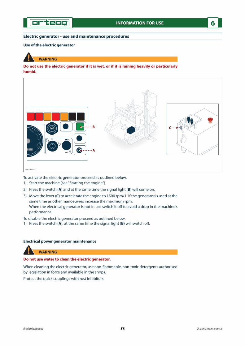
UN21-0507CO
CB
A
English language 58 Use and maintenance
INFORMATION FOR USE 6
To activate the electric generator proceed as outlined below.1) Start the machine (see “Starting the engine”).
2) Press the switch (A) and at the same time the signal light (B) will come on.
3) Move the lever (C) to accelerate the engine to 1500 rpm/1’. If the generator is used at the same time as other manoeuvres increase the maximum rpm.
When the electrical generator is not in use switch it o� to avoid a drop in the machine’s performance.
To disable the electric generator proceed as outlined below.1) Press the switch (A): at the same time the signal light (B) will switch o�.
Electric generator - use and maintenance procedures
WARNING
Do not use the electric generator if it is wet, or if it is raining heavily or particularly humid.
Electrical power generator maintenance
WARNING
Do not use water to clean the electric generator.
When cleaning the electric generator, use non-�ammable, non-toxic detergents authorised by legislation in force and available in the shops.
Protect the quick couplings with rust inhibitors.
Use of the electric generator

UN21-0544AP
PQ
BDC
ED
B
A
F
NP
M
S
R
T
LHH
G
English language 59 Use and maintenance
INFORMATION FOR USE 6
Blade raiser - instructions for assembly, use, and maintenance
This accessory is used to lift up the segments of guardrail (already bolted and laid on the ground).Using the machine's travel motion, the accessory raises the guardrail, positions it in the point of installation and provides the exact location where the pile needs to be driven in.The blade raiser can be supplied to the customer already �tted on the machine or shipped separately, partially disassembled and protected by appropriate packaging.
Blade raiser assembly
WARNING
Use lifting means with a su�cient capacity for the load to be lifted.Hooks and ropes in good condition suitable for the load to be lifted must be used for lifting operations.
Proceed as outlined below.1) Strap up and lift the separate units (A - F - M) comprising the accessory properly. 2) If necessary, �t the shims (T) supplied with the accessory in order to reduce the clear-
ance between the frame (A) and the supports (B).3) Slide the frame (A) into the supports (B) welded to the crawler. 4) Insert the screws (C) and the washers (D).5) Tighten the nuts (E).6) Position the arm (F).7) Insert the screws (G) and the washers (H).8) Tighten the nuts (L).9) Position the head (M).10) Insert the screws (N) and the washers (P).11) Tighten the nuts (Q).12) Connect the hydraulic pipes to the quick couplings (R - S).

UN21-0545AP
H
D
E B
AA
C1
UN21-0546AP
D
E
F
AA
English language 60 Use and maintenance
INFORMATION FOR USE 6
Blade raiser removal
Proceed as outlined below.1) Disconnect the �ttings (R - S).
2) Separate and remove the individual units working in reverse order to the procedure described for the assembly.
Adapting the accessory to the size of the guardrail
The accessory is usually supplied in the con�guration (1) illustrated in the �gure.Check that the height of guardrail (H) is compatible with the height of the guide.Should it be necessary to install a lower guardrail, perform the procedure de-scribed.Proceed as outlined below.1) Remove the safety lock pins (A).2) Slide out the pins (B).3) Remove the rollers (C).4) Undo the screws (D).5) Remove the bracket (E).
6) Position the bracket (E) aligned with the lower holes.
7) Tighten the screws (D).8) Insert the appropriate pins (F) provid-
ed with the accessory.9) Insert the safety lock pins (A).

UN21-0547AP
0
2
1
C
B
D
A
UN21-0548AP
A
B
English language 61 Use and maintenance
INFORMATION FOR USE 6
Use of the blade raiser
A) Lever: this is used to activate the ex-tension and retraction of the head on the blade raiser.
- Use the lever (1) to extend the head and bring the guardrail near the pile.
- Set the lever in position (2) to retract the head and move the guardrail away from the pile.
Proceed as outlined below.1) Position the machine in the spot
where work needs to begin.2) Bolt the guardrail segments together
and lay them on the ground.3) Insert the end of the �rst segment
into the guide.4) Use the lever (A) to position the
guardrail in the fastening position en-visaged in the design.
5) Check that the surface of the guard-rail is fully in contact with the mount-ing surface of the pile.
If the guardrail is not perfectly in con-tact, proceed as described below.
- Loosen the nut (B).- Adjust the tie rod (C). - Tighten the nut (B).6) Check that the holes in the guard rail are aligned with the holes in the pole. If the holes are not aligned, turn the �ywheel (D) to move the guide vertically.7) Bolt the barrier onto the �rst pile before moving on to the next one.8) Move forwards with the machine until you reach the position where the next pile needs
to be driven in.
Adjusting the clearance of the extendable arm
Carry out the operations described.1) Use the adjustment screw to reduce
the clearance between the �xed arm (A) and the telescopic arm (B) to a minimum.

UN21-0549AP
English language 62 Use and maintenance
INFORMATION FOR USE 6
Maintenance of the blade raiser
Carry out scheduled maintenance as stated by the manufacturer (see "Sched-uled maintenance charts").Carry out the operations described.1) Check the tightness of the main nuts
and bolts (see section on scheduled maintenance).
2) Clean and lubricate the surface of the side of the extendable arm.
Grease type: use PAKELO BEARING EP2 or equivalent.
3) Grease the components with the spe-cial greasing nozzles.
Grease type: use PAKELO BEARING EP2 or equivalent.
Pointed bit - instructions for assembly, use, and maintenance
This kind of tool can be used to drill holes in the ground (even in ground containing some solid materials with small particle sizes, such as gravel, crushed stone, etc.).
The tool makes the hole in the ground into which the pile will be �tted, without producing any spoil.
Fitting the tool
WARNING
Fit the tool with the machine parked on �at, �rm ground, with the engine stopped and the hammer drill far enough o� the ground to facilitate assembly.Arrange appropriate safety measures and use suitable equipment to avoid accidents that could injure the people in charge of the operation and people nearby.
Carry out the operations described.1) Move the lever (D) and rest the percussion hammer on a surface su�ciently strong to
bear the weight of the hammer.
2) Unscrew the nuts (A).
3) Remove the screws (B).
4) Gently move the lever (D) and carefully lift the percussion hammer. The components (E - F) and the unit (H) will remain on the support surface.

UN21-0550AP
P
B
A
CG
H
B
D
A
B
E
F
G
E
L
F
A
R
Q
S
T
English language 63 Use and maintenance
INFORMATION FOR USE 6
5) Unscrew the unit (H) and the components (E -F).6) Remove the components (G) from the component (C). 7) Position the components (G) on the new component (L).8) Position the stop plate (E). 9) Position the component (F).
CAUTION
Pay particular attention to the component (F) which could fall and injure the opera-tor.
10) Gently move the lever (D) and carefully lower the percussion hammer.11) Insert the screws (B).12) Tighten the nuts (A).13) Move the lever (D) to lift the percussion hammer.14) Position the tool (P) below the hammer drill.15) Use the lever (D) to lower the hammer drill and insert the tool into its seat.16) Position the washer (R). 17) Insert pin (Q).18) Position the washer (S). 19) Insert the lock pin (T).

UN21-0551AP
R0
B3
R
Y
C
B
English language 64 Use and maintenance
INFORMATION FOR USE 6
Procedure for drilling holes
WARNING
Holes may be drilled in sloping ground, subject to the limits set by the manufacturer.On sloping ground position the machine with the pile driver as close as possible to the truck to reduce the risk of tipping over.
Carry out the operations described.
1) Drive the machine to the area where the hole is needed (see section on travel mode).
When drilling a hole, it is important to position the hammer drill perfectly verti-cal either manually (see "Operating con-trols"), or automatically (see "Procedure for use of the verticality system").
To manually place the column in a per-fectly vertical position use the level gauge (C).
The operator must be positioned as shown in the �gure.
2) Place the column in a perfectly verti-cal position.
3) Using the lever (B), lower the tool un-til it is touching the ground.
4) Set the lever (B) in the �oating posi-tion "B3".
NOTICE
Make sure that the automatic vertical-ity system is disabled before activat-ing the percussion hammer, to avoid damaging the device.
5) Move the lever (R) to activate the percussion hammer.
NOTICE
When working on extremely hard ground, it is important not to use a pneumatic drill for more than 30 seconds at a time.After this limit, stop for at least 15 seconds before resuming drilling.If the tool does not go into the ground, do not attempt to force it; there is probably an obstruction preventing it from being driven in fully.
NOTICE
To automatically stop the tool at the required depth, see "Adjusting the PROXIMITY device for stopping the hammer downstroke".If the machine is �tted with the laser device see the “Adjusting the laser device that stops the hammer’s down stroke” section.
Y) Control position foreseen for the operator

UN21-0552AP
UN21-0490BO
B
A
2
1 C
English language 65 Use and maintenance
INFORMATION FOR USE 6
6) Once the required depth has been reached move the lever (R) to position "R0" to stop the percussion or activate the automatic stop devices (Proximity and laser).
7) Use the lever (B) to lift the hammer drill and remove the tool from the hole.
8) Drive the machine to the area where the hole is needed (see section on travel mode).
Removing the tool
To remove the tool, carry out the steps in reverse order to the procedure described for the assembly.
Tool maintenance
Carry out scheduled maintenance as stated by the man-ufacturer (see "Scheduled maintenance charts").Proceed as outlined below.1) Before carrying out any lubrication work, clean the
greasing nozzle, to prevent pollution of the lubri-cant.
2) Lubricate via greasing nozzle. Grease type: use PAKELO BEARING EP2 or equivalent.
Automatic verticality system - instructions for use
General description
The verticality system is used to automatically place the column in vertical position.The main components of the verticality system are shown in the �gure.

UN21-0490BO
B
A
2
1 C
UN21-0491BO
XY
A B C
D
E
English language 66 Use and maintenance
INFORMATION FOR USE 6
A) Control panel: to manage the column automatic verticality system.
B) Electronic control unit: to check the vertical position of the column by means of soft-ware incorporated in the component.
The software can be updated or reinstalled via personal computer connected to the can/usb gateway (1) connector or via the internet (remote assistance).
The 10A fuse (2) protects the electronic control unit against overcurrents.
C) Angular sensor: the sensor detects the incorrect position of the column and sends the signal to the electronic control unit, which switches on the red signal lights and the green signal light.
Controls and signals/gauges
A) Key switch: to activate the automatic verticality sys-tem functions.
B) Red signal light. - Signal light o�: this indicates the correct vertical
position of the column in relation to the axis (X). - Signal light on: this indicates the incorrect vertical
position of the column in relation to the axis (X). - Flashing signal light: this indicates that the auto-
matic verticality system is out of range due to the excessive inclination of the column compared to the axis (X).
C) Red signal light. - Signal light o�: this indicates the correct vertical
position of the column in relation to the axis (Y). - Signal light on: this indicates the incorrect vertical
position of the column in relation to the axis (Y). - Flashing signal light: this indicates that the auto-
matic verticality system is out of range due to the excessive inclination of the column compared to the axis (Y).
D) Illuminated momentary pushbutton (green light). - Pushbutton on: this shows that the system is ready to activate the vertical positioning
of the column. One or both signal lights (B) and (C) are on. - Pushbutton o�: the column is in perfectly vertical position. The system goes auto-
matically into stand-by. E) Momentary pushbutton: this is used to reset the column verticality system.

UN21-0492BO
XY
B C
D
A
UN21-0554AP
L3
B
AC
D
E
LF
H
G
English language 67 Use and maintenance
INFORMATION FOR USE 6Automatic verticality system operating mode
Carry out the operations described.1) Position the column near the pile to be driven into
the ground (see “Pile driving procedure”).2) Turn the key of the switch (A) to position “I”. One or both the signal lights (B) and (C) may switch
on and the illuminated pushbutton (D) will light up.3) Press pushbutton (D) to activate the vertical position-
ing of the column in relation to axis (X) and axis (Y). Signal lights (B) and (C) and pushbutton (D) switch o�
when the column is perfectly vertical. At the end of each cycle, the system goes automatically into stand-by.
4) Turn the key of the switch (A) to position “0” to dis-able the automatic verticality device.
NOTICE
Do not activate the automatic verticality device while the pile is being driven into the ground, to avoid dam-aging the device.
System for adjusting/reducing the hammer drill frequency - instructions for use
The device, which is ideal for driving piles into soft ground, reduces the stroke frequency during the �nal driving stage.
The reduction of the stroke frequency allows greater pile driving accuracy.
The driving depth at which the stroke frequency may be reduced is determined by the distance between sensors (F - G).
Usually, the distance between the two sensors is speci�ed when the customer places the order.

UN21-0554AP
L3
B
AC
D
E
LF
H
G
English language 68 Use and maintenance
INFORMATION FOR USE 6
A) Two-position permanent-contact switch: this is used to activate and deactivate the hammer drill strokes and the stroke frequency reduction device for the said hammer drill hammer.
B) Signal light (green light): this signals the activation and deactivation of the switch (A).
C) Knob: this is used to gradually reduce the hammer drill stroke frequency.
D) Key-operated switch: this is used to activate the features of the system for adjusting/reducing the hammer drill frequency.
Proceed as outlined below.1) Turn the key of the switch (D) to position “I”.
2) Use the lever (L) to lower the hammer drill onto the pile until the head of the pile is �tted inside the grooved pro�le of the stop plate and then set it in the �oating position “L3”.
3) Use switch (A) to start the hammer drill working and activate the system. The indicator lamp (B) lights up.
4) Use the knob (C) to reduce the hammer drill stroke frequency. When the device (H) activates the sensor (G) during the downward stroke of the ham-
mer drill, this starts to reduce the preset frequency. When the device (H) activates the sensor (F), the pile driving stops.
5) Use switch (A) to stop the hammer drill working and deactivate the system. The signal light (B) will switch o�.
6) Move the lever (L) to lift the percussion hammer.
7) Move the machine to the point where the next pile is to be driven in.

UN21-0555AP
A
B
C
D E F
G
L
H
UN21-0556AP
1000 mm
Q N
P M
R
English language 69 Use and maintenance
INFORMATION FOR USE 6
Fitting the magnet
Proceed as outlined below.1) Position the pile guide (A).2) Insert the pins (B).3) Insert the safety lock pins (C).4) Position the plate (D).5) Position the washers (E).6) Tighten the screw (F).7) Position the shackle (G).8) Tighten the lock pin (H).9) Connect the electrical cable (L).
Controls and signals/gauges
M) Two-position permanent-contact switch: this is used to activate and deactivate the magnet.
N) Signal light (green): this shows that the magnet is switched on.
P) Signal light (orange): this shows that the magnet is about to switch o� (within 5 seconds).
Q) Audio warning device: this audio signal means that the magnet will switch o� within 5 seconds.
Use of the magnet
Proceed as outlined below.1) Clean the magnet grip surface and the pile contact surface.
2) Position the magnet in the centre of the pile at the distance from the head shown in the �gure.
3) Run the safety cable (R) around the pile.
4) Use the switch (M) to activate the magnet. The indicator lamp (N) lights up.
Magnets - instructions for assembly, use, and maintenance
The magnet is used to lift particularly large ferromagnetic piles into the driving position.

UN21-0557AP
S
RU
Q N
P M
T
A
English language 70 Use and maintenance
INFORMATION FOR USE 6
5) Use the lever (S) to lift the pile.
NOTICE
Use a lever (T) to manoeuvre around the pile guide plate (U).
6) Once the vertical position is reached, place the pile inside the guide (A) manually and insert it into the stop plate.
7) Drive the pile down to the required depth (see "Pile driving procedure").
8) Use the switch (M) to deactivate the magnet.
At the same time, the signal light (N) switches o�, the signal light (P) comes on, and the audio signal sounds (Q).
After 5 seconds, the signal lights (N - P) switch o�, the audio signal stops sounding, and the magnet is no long-er attracted to the pile.
9) Release the pile from the safety line (R).
Removing the magnet
To remove the magnet, carry out the steps in reverse order to the procedure described for the assembly.
Magnet maintenance
When cleaning the magnet, use non-�ammable, non-toxic detergents authorised by legis-lation in force and available in the shops.

UN21-0559AP
R
G
F
D
E
H
N
N
P
Q
L
UN21-0558AP
D
B
A
C
English language 71 Use and maintenance
INFORMATION FOR USE 6
Assembling the system for measuring the distance between the piles
Fit the system based on the direction in which the ma-chine drives.The �gure shows the system �tted based on the machine travel direction (D).If the travel direction is the opposite to that shown in the �gure, �t the system in the same way on the opposite side of the column.Carry out the operations described.1) Insert the pin (A) into the bushing (B). 2) Connect the connector (C).
Use of the system for measuring the distance between the piles
Adjust the system according to the distance (L) between the piles to be driven in.
The maximum distance (L) allowed is 4000 mm.
Carry out the operations described.1) Drive the �rst pile into the ground (see "Pile driving procedure").2) Move the machine to the point where the next pile is to be driven in.
System for measuring the distance between the piles - instructions for as-sembly, use, and maintenance
The system for measuring the distance between the piles is used when driving in piles (made of either metal or another material) to keep the same distance between the piles.

UN21-0559AP
R
G
F
D
E
H
N
N
P
Q
L
English language 72 Use and maintenance
INFORMATION FOR USE 6
3) Using a tape measure, check the distance between the two piles.
4) If necessary, use the levers (F - G) to position the hammer drill and the pile exactly in the spot where the second pile will be positioned.
5) Drive the second pile into the ground (see "Pile driving procedure").
6) Do not move the machine away from the pile driving position.
7) Loosen the screw (D).
8) Move the photocell (E) to the spot where the signal light (R) comes on.
9) Tighten the screw (D).
If the movement of the photocell alone is not enough, proceed as described below.10) Unscrew the nut (P).
11) Remove the screws (H).
12) Remove the washers (N).
13) Slide out the tubular bar (Q) until the holes for fastening the tubular bar in the open con�guration are aligned.
14) Position the washers (N).
15) Insert the screw (H).
16) Tighten the nut (P).
17) Loosen the screw (D).
18) Move the photocell (E) to the spot where the signal light (R) comes on.
19) Tighten the screw (D).
20) Drive the machine to the point at which the next pile will be driven in.
21) When the signal light (R) switches on, it means the position for the next pile has been reached.

UN21-0494BO
AON
OFF
English language 73 Use and maintenance
INFORMATION FOR USE 6
Removal of the system for measuring the distance between the piles
To remove the system for measuring the distance between the piles, carry out the steps in reverse order to the procedure described for the assembly.
Maintenance of the system for measuring the distance between the piles
Carry out scheduled maintenance as stated by the manufacturer (see "Scheduled mainte-nance charts").
When cleaning the system for measuring the distance between the piles, use non-�amma-ble, non-toxic detergents authorised by legislation in force and available in the shops.
Lighting - instructions for working at night or in poor visibility conditions
Working at night or in low visibility conditions increases the risks that derive from the use of the machine.
In case of work at night or in low visibility conditions use the switch (A) to switch on the lights to illuminate the work area.
The position of the lights is shown in the �gure.
English language 74 Use and maintenance
INFORMATION FOR USE 6
Refuelling
WARNING
Do not �ll the fuel tank completely when the machine is exposed to the sun as the fuel may spill out and catch �re.
NOTICE
The fuel must comply with the speci�cations provided by the manufacturer of the engine (see the engine manufacturer’s user manual).
For the good working order of the engine, the fuel must be free from suspended impurities; therefore it must decant for a suitable amount of time.
It is advisable to refuel before the tank is completely empty to stop the injection pump from sucking in air. In this case, �ll the fuel tank and, with the engine o� and cool, bleed the fuel circuit (see the use and maintenance manual provided by the engine manufacturer).
The supply gun must always be in contact with the tank opening until refuelling is com-plete to avoid the risk of electrostatic sparks between the supply gun and the tank opening which could lead to the fuel catching �re or the tank exploding.
Long out-of-use periods
When the machine is not going to be used for long periods of time proceed as follows.1) Wash the machine completely.
2) Grease the machine (see “Lubrication diagram”).
3) Fix any oil leaks (hydraulic and engine circuits).
4) Repair damaged or worn mechanical parts (tracks, etc.).
5) Protect the unpainted parts with antioxidant products.
6) Empty the fuel tank completely.
7) Turn the battery cut-o� switch to open the circuit and remove the battery.
8) Park the machine in a sheltered place, where it can only be accessed by authorised per-sonnel.
- If the engine is not going to be used for a long period of time see the engine manu-facturer’s manual.
Re-commissioning
Before starting up the machine after a long period out-of-use proceed as follows.1) Check the pressure of the accumulator of the percussion hammer.2) Check the condition of the battery.3) Re�t the battery and turn the cut-o� switch to close the circuit.4) Remove the antioxidant from the unpainted parts.5) Check that the main �xing nuts and bolts are tight.6) Check all oil levels.7) Fill the fuel tank.8) Start the engine at minimum for the time necessary to heat the engine.9) Check the e�ciency of the safety devices.- To start up the engine again see the engine manufacturer’s manual.

UN21-0039DL
A
UN21-0493BO
D
A
B
E
T
C
English language 75 Use and maintenance
INFORMATION FOR USE 6
Operational stop
Proceed as outlined below.1) Remove any accessories from the machine.
2) Close the machine in the resting position (A).
3) Park the machine on solid and even ground.
4) Use the accelerator lever (B) to reduce to a minimum the rpm.
5) Turn the ignition key (C) to position (0) to switch o� the engine.
6) Remove the ignition key (C) from the dashboard and keep it in a safe place.
7) Close the dashboard guard (E) and assess the need to padlock it to avoid tampering of the controls and prevent unauthorised use of the machine.
8) Turn the battery cut-o� switch (D) to open the circuit and isolate the battery.
9) Close the valve (T).
10) If necessary signal the presence of the parked machine.
Emergency stop
Press the emergency button (A), only in the case of im-minent danger, to immediately stop all machine move-ments.Eliminate the cause of the emergency stop before re-starting the machine (see “Starting the engine”).

English language 76 Use and maintenance
MAINTENANCE INFORMATION 7Safety advice for maintenance
To protect the people involved, maintenance operations must be carried out with all safety devices activated and unauthorised people must not be allowed to access the area of operation which must be appropriately marked.Before starting the machine, check that there are no tools, cloths or other material near the moving parts or in risk areas.In the case of maintenance operations which cannot be performed from the �oor sur-face, a suitable ladder in compliance with the safety at work regulations in force must be used.Carry out the maintenance operations envisaged by the machine’s manufacturer to ensure the machine remains safe and in good working order (see and �ll out the “Maintenance register”).All maintenance operations not provided for in this chapter must be carried out by authorised and quali�ed maintenance personnel.Perform the scheduled maintenance activities required for the engine (see the "En-gine instruction manual" provided with this manual).
(1) At this use rate, the oil is changed only the �rst time.(2) To be checked more often in case of intensive use of the machine.
Scheduled maintenance chart (operator)
Interval Component Type of work Reference
Every 4 hours of work
Stroke plate
Hammer point
Nuts and bolts
Accessories and supplements
Drilling machine
Greasing
Greasing
Inspection
Nut and bolt tightness check
Greasing
See “Lubrication diagram”
See “Lubrication diagram”
See “Nuts and bolts check”
At the end of the work
Core borer
Core borer water pipeline
Drill
Accessories and supplements
Cleaning
Rust inhibitor
Cleaning
Cleaning
Condition inspection
See “Core borer maintenance”
See “Core borer maintenance”
See “Drill maintenance”
Scheduled maintenance chart (maintenance engineer)
Interval Component Type of work Reference
Every 100 hours of work
Track reduction gear
Percussion hammer lifting chain
Slide
Inside of the column
Drill
Core borer
Drilling machine (RP500)
Oil level checkOil change (1)
Cleaning and lubrication (2)
Check
Lubrication
Lubrication
Oil change (1)
Greasing
Checking the gear unit oil level
Spring adjustment
See “Track gearmotor oil level check”See “Replacing the track reduction gear oil”See “Cleaning and lubrication of hammer lifting chain”
See “Replacing the chain”
See “Lubrication diagram”
See “Lubrication diagram”
See “Drill maintenance”
See “Core borer maintenance”
See “Drilling machine maintenance”
See “Drilling machine maintenance”

English language 77 Use and maintenance
MAINTENANCE INFORMATION 7
Scheduled maintenance chart (maintenance engineer)
Interval Component Type of work Reference
Every 250 hours of work
Tracks Tension check See “Track tension check”
Every 500 hours of work
Hydraulic oil tank
Pile extraction gripper
Blade raiser
Oil level check
CleaningGreasing
Greasing
See “Hydraulic oil level check”
Every 1000 hours of work
Tracks gearmotor
Hydraulic oil delivery line �lter
Hydraulic oil discharge �lter
Hydraulic oil delivery line �lter
Drill
Drilling machine
Oil change
Check the �lter cartridge cloggingReplacing the �lter cartridge
Replacing the �lter cartridge
Replacing the gear unit oil.
Replacing the gear unit oil
See “Replacing the track reduction gear oil”
See “Replacing the discharge �lter cartridge (low pressure)”
See “Replacing the delivery line �lter cartridge (high pressure)”
See “Drill maintenance”
See “Drilling machine maintenance”
Scheduled maintenance chart (specialist technician)
Interval Component Type of work Reference
Every 250 hours of work
Hammer drill accumulator diaphragm
Tie-rods and bolts
Condition check
Condition and tightness inspection
Carry out check at an authorised service centre
Every 1000 hours of work Percussion hammer lifting chain Replacement See “Replacing the chain”
Every 2000 hours of work Hydraulic oil tank Oil change Contact an authorised service centre

UN21-0495BO
4 h 4 h 4 h 100 h 4 h 200 h
500 h
English language 78 Use and maintenance
MAINTENANCE INFORMATION 7
PAKELO HAMMER GREASE PLUS NLGI 2
PAKELO BEARING EP2
PAKELO BEARING EP2
Oil for chains PAKELO HYDRAULIC EP ISO 46
PAKELO GEAR OIL EP/EGL-5 SAE 80W/90
Lubrication diagram
Lubricate the parts as shown in the illustration.Before lubricating, clean the components concerned and the greasing nipples to prevent contamination of the lubricant.
The lubricants indicated are factory �ll lubricants.For equivalent lubricants see the “Lubricant comparison table”.

UN21-0496BO
A
B
UN21-0497BO
D
E
C
English language 79 Use and maintenance
MAINTENANCE INFORMATION 7
Nut and bolt check
Check that the main �xing nuts and bolts are tight.If the bolts are loose tighten them to the prescribed torque (see the “Nuts and bolts tighten-ing torques chart”).
Checking and cleaning the supplementary air �lter
NOTICE
Never carry out maintenance operations on the air �lter with the engine on to pre-vent dirt and debris suspended in the air from seriously damaging the engine.In certain operating conditions (dust, dirt and debris), the air �lter may need to be checked and cleaned more frequently.
Use the valve (A) to release the dust contained in the �l-ter.Check the clog signal (B) every day.When the signal is in the red area, it means the �lter is clogged and must be cleaned or replaced (see “Replac-ing supplementary air �lter cartridges”).
For checking and cleaning operations proceed as out-lined below.
- Pre-�lter1) Unscrew the wing nut (C).2) Remove the cover (D).3) Remove any dirt or debris from the pre-�lter (E).4) Re�t the cover (D).5) Tighten the wing bolt (C).

UN21-0180EI
F
HG
L
UN21-0181EI
N
M
English language 80 Use and maintenance
MAINTENANCE INFORMATION 7
- Primary �lter
6) Unscrew the wing nut (F).
7) Remove the cover (G).
8) Unscrew the wing nut (H).
9) Slide out the primary �lter (L).
If the �lter is clogged do not beat it to remove the dust.
Do not wash the �lter.
Use low pressure compressed air to remove the dust from the �lter.
Direct the �ow of air vertically along the folds of the �l-tering material, from the inside outwards.
Be careful not to damage the folds of the �ltering ele-ment.
The primary �lter can be cleaned up to six times (if cleaned and checked correctly), then it must be replaced.
If the �lter is damaged (torn �ltering material, damaged seals) it must be replaced.
- Secondary �lter
10) Unscrew the wing nut (M).
11) Slide out the secondary �lter (N).
Check the clogging level of the �lter and if neces-sary replace it.
After having checked and cleaned the �lters (to assess the need to replace them) �t the �lters following the removal sequence in reverse order.
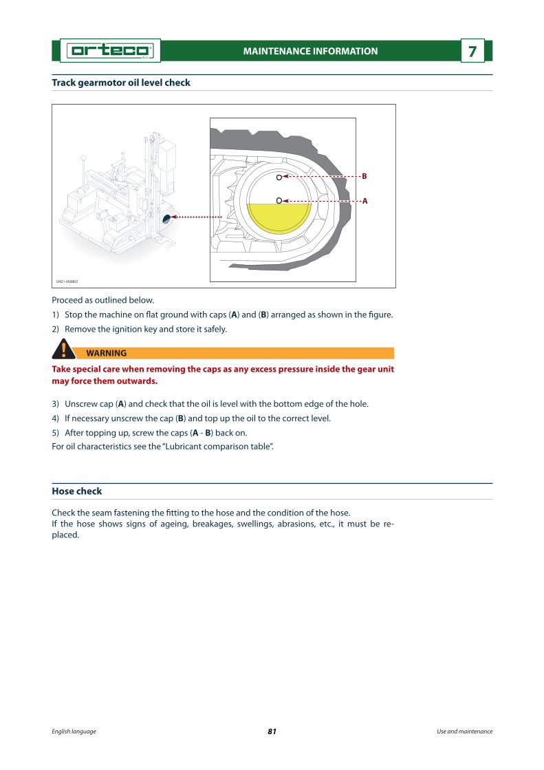
UN21-0508EO
B
A
English language 81 Use and maintenance
MAINTENANCE INFORMATION 7
Track gearmotor oil level check
Proceed as outlined below.
1) Stop the machine on �at ground with caps (A) and (B) arranged as shown in the �gure.
2) Remove the ignition key and store it safely.
WARNING
Take special care when removing the caps as any excess pressure inside the gear unit may force them outwards.
3) Unscrew cap (A) and check that the oil is level with the bottom edge of the hole.
4) If necessary unscrew the cap (B) and top up the oil to the correct level.
5) After topping up, screw the caps (A - B) back on.For oil characteristics see the “Lubricant comparison table”.
Hose check
Check the seam fastening the �tting to the hose and the condition of the hose.If the hose shows signs of ageing, breakages, swellings, abrasions, etc., it must be re-placed.

UN21-0499BO
10 - 15 mm
UN21-0500BO
max
minC
A
B
English language 82 Use and maintenance
MAINTENANCE INFORMATION 7
Track tension check
Proceed as outlined below.
1) Stop the machine on solid and even ground.
2) Switch o� the engine and remove the ignition key and keep it in a safe place.
3) Lift the tracks o� the ground.
4) Lock the machine lifted from the ground using ap-propriate external means (stands, etc.).
5) Check track tension.
Tension is correct when the tension at the centre track roller is between 10 and 15 mm.
6) If necessary adjust the track to the correct tension (see “Adjusting track tension”).
Hydraulic oil level check
Proceed as outlined below.
CAUTION
Slowly unscrew the cap and discharge the pressure inside the tank to prevent the danger of burning caused by the expulsion of hot liquid.
1) Stop the machine on solid and even ground and the pile driver in resting position with all jacks retracted.
2) The oil gauge level (A) must be between min. and max.3) If necessary unscrew the pressurised �lling cap (B) and top up the oil to the correct
level.4) Once topped up screw the cap (B) back on.For oil characteristics see the “Lubricant comparison table”.Level gauge (A) includes a thermometer (C) that shows the oil temperature inside the tank.

English language 83 Use and maintenance
MAINTENANCE INFORMATION 7
Cleaning and lubrication of hammer lifting chain
WARNING
The percussion hammer lifting chain is a fundamental safety device therefore it must be maintained e�cient through regular maintenance.
The lifting chain wears quickly if it is not regularly lubricated.The lubrication frequency shown in the maintenance schedule chart refers to normal use.If the chain is exposed to greater stress (dust, temperature, or intensive use) the chain must be lubricated more often.If the chain is damaged, worn, corroded, etc., it must be replaced immediately (see “Replac-ing the chain”).
Proceed as outlined below.
1) Stop the machine on solid and even ground.
2) Switch o� the engine and remove the ignition key and keep it in a safe place.
3) Clean the chain with diesel oil or petrol or a para�n-derived product.
4) Lubricate with spray lubricant for chains following the indications.
During this operation the chain must not be tensioned.
NOTICE
To avoid damaging the chain, do not clean it with steam jets and corrosive deter-gents.
Machine cleaning
Clean the jack rods to avoid dirt build-up.
Wash the machine with a high-pressure water jet using legally approved non-toxic and non �ammable detergents.
NOTICE
Do not spray the water on the electrical parts, as this could damage them.

English language 84 Use and maintenance
MAINTENANCE INFORMATION 7
Note: friction coe�cient (0,125)
Thread diameterTightening torque (Nm)
Resistance class 8.8 Resistance class 10.9 Resistance class 12.9
M6 9.5 13.0 16.0
M8 23.0 32.0 39.0
M10 46.0 64.0 77.0
M12 80.0 110.0 135.0
M14 125.0 180.0 215.0
M16 195.0 275.0 330.0
M18 270.0 390.0 455.0
M20 385.0 540.0 650.0
M22 510.0 720.0 670.0
M24 660.0 930.0 1100.0
M27 980.0 1400.0 1650.0
M30 1350.0 1850.0 2250.0
Hydraulic oil - suitable for room temperature of -20 to +40 °C
Brand PAKELO IP AGIP MOBIL SHELL
Type HYDRAULIC EP ISO 46
HYDRUS OILHI 46 ENI-ARNICA 46 DTE 10 EXCELL SHELL
TELLUS S2 V 46
Grease
Brand PAKELO IP AGIP MOBIL SHELL
Type BEARIN EP2 ATHESIA PGX 2 ENI - GREASE MU EP 2 MOBILUX EP 2 ALVANIA
GREASE EP
Molybdenum disulphide grease (speci�cally for the point and stroke plate)
Brand PAKELO IP AGIP MOBIL SHELL
TypeHAMMER GREASE
PLUS NLGI 2 BIMOL LTM ENI - GREASE SM 2 MOBILGREASE SPECIAL SHELL RETINAX HDX
Engine oil - standard climates Brand PAKELO IP AGIP MOBIL SHELL
TypeGOLDEN DIESEL
HP/A SAE 15W/40TARUS TURBOEXTRA 15W/40
I SIGMA PERFORMACE E7
DELVAC MX 15W/40
RIMULA R 4 X 15W/40
Track gearmotor oilBrand PAKELO IP AGIP MOBIL SHELL
Type GEAR OIL EP/E GL-5 SAE 80W/90
PONTIAX 80W/90 EP GL-5 BLASIA GEAR
A 80W/90 SPIRAX A 80W/90
Lubricant comparison table
Nuts and bolts tightening torques chart
Engine oil - cold climates Brand PAKELO IP AGIP MOBIL SHELL
TypeGOLDENSTAR LA
77 - 51 SAE 5W/30TARUS TURBO
SYNTETIC 5W/30 I SIGMA
TOP 5W/30DELVAC
1 LE EW/30 RIMULA R 6 ME

English language 85 Use and maintenance
BREAKDOWN INFORMATION 8
Fault Likely cause Solution Reference
Hammer percussion is not regular
Cold oil Repeat machine movements several times to heat the oil
Weak hammer percussionFlat accumulator
RechargeContact an authorised service centre
(*)
Damaged accumulator Replace the membrane
Percussion gets blocked
Excessive oil counter pressure in return pipe
Restore the correct counter pressure
Contact an authorised service centre
Excessive oil deliveryRestore the correct oil delivery
Loose nuts of the percussion hammer’s tie rod
Tighten the nuts
Faulty hydraulic system Restore the hydraulic system
The engine switches o� immediately after start-up
The emergency button has been accidentally pressed
Deactivate the emergency button
The electrical system of the emergency button in faulty
Repair the faultContact an authorised service centre
Locking machine movements
Maximum pressure valves of the distributors clogged with dirt
Clean the valves Contact an authorised service centre
The accessory does not switch on
The hydraulic supply by-pass valve lever is in the hammer activation position
Turn the valve lever to the correct position
The accessory does not work correctly
See the instruction manual of the accessory’s manufacturer
The machine does not have the original operating speed and percussion power
Damaged pump Replace the pump
Contact an authorised service centre
Damaged PTO Replace the PTO
Main pressure valve not calibrated correctly
Set correct calibration
(*) If the accumulator has worked for a prolonged period at a pressure below 20 bar, replace the membrane
Safety advice in case of faults
Repairs that require speci�c technical competence or special skills must be carried out only by an authorised service centre.

UN21-0501BO
C
B
D
F
E
G
A
English language 86 Use and maintenance
INFORMATION CONCERNING REPLACEMENTS 9
Safety advice in case of replacements
To protect the people involved, the replacement of parts must be carried out with the machine cut-o� from any power source and unauthorised people must not be al-lowed to access the area of operation which must be appropriately marked.
Replace worn components with original spare parts.
The manufacturer shall not be liable for any damage to objects or persons caused by the use of non-original parts and spare parts.
Before starting the machine, check that there are no tools, cloths or other material near the moving parts or in risk areas.
Components and waste material must be disposed of in compliance with the law in force concerning waste collection, sorting and disposal.
Replacing the discharge �lter cartridge (low pressure)
CAUTION
The �lter cartridge must be replaced with the hydraulic system depressurised.
Replace the �lter cartridge when the needle of the clog indicator (A) is in the red area or in any case at the intervals shown in the “Scheduled maintenance chart”.
Proceed as outlined below.
1) Clean the �lter's outer surfaces accurately.
2) Unscrew the screws (B) and remove the cover (C).
3) Remove the spring (D) and the �lter cartridge (E).
4) Remove the gaskets (F) and (G) and replace them if damaged.
5) Fit the new �lter cartridge, the gaskets (F) and (G), the spring (D) and the cover (C).6) Tighten the screws (B).

UN21-0502BO
L
AC
B
UN21-0187EI
F
HG N
M
L
English language 87 Use and maintenance
INFORMATION CONCERNING REPLACEMENTS 9
Replacing the delivery line �lter cartridge (high pressure)
CAUTION
The �lter cartridge must be replaced with the hydraulic system depressurised.
Replace the �lter cartridge when the signal (L) lights up and remains constantly switched on for a few minutes.
Proceed as outlined below.
1) Position a container of adequate capacity under the �lter to collect the oil.
2) Clean the �lter's outer surfaces accurately.
3) Unscrew the �lter unit (B).
4) Slide out the worn or clogged �lter cartridge (A).
5) Accurately clean the inside of the �lter unit (B).
6) Slide the new �lter cartridge into the �lter unit.
7) Check the state of the seal (C) and if damaged replace it.
8) Tighten the �lter unit (B).
Replacing supplementary air �lter cartridges
NOTICE
Never replace air �lter cartridges with the engine on to prevent dirt and debris sus-pended in the air from seriously damaging the engine.

UN21-0508EO
A
B
English language 88 Use and maintenance
INFORMATION CONCERNING REPLACEMENTS 9Proceed as outlined below.
1) Unscrew the wing nut (F).
2) Remove the cover (G).
3) Unscrew the wing nut (H).
4) Slide out the primary �lter (L).
5) Unscrew the wing nut (M).
6) Slide out the secondary �lter (N).
Fit the new �lter cartridges following the removal sequence in reverse order.
Replacing hosing
CAUTION
The hosing must be replaced with the hydraulic system depressurised.
To depressurise the system stop the engine and move the shift control levers in both direc-tions.
Unscrew the hosing �ttings and collect the oil in a suitable container.
Replace hosing and tighten the �ttings.
Replacing the track reduction gear oil
3) Unscrew the caps (A - B) and allow the oil to run into a su�ciently sized container.
4) Wait a few minutes, until all the oil has drained out.
5) Re�ll the oil as shown (see “Oil level check for track gear units”).
6) Screw on the caps (A - B).
For oil characteristics see the “Lubricant comparison table”.
NOTICE
Never dump the oil.It must be disposed of in compliance with applicable laws.
Proceed as outlined below.1) Stop the machine on �at ground with
caps (A) and (B) arranged as shown in the �gure.
2) Remove the ignition key and store it safely.
WARNING
Take special care when removing the caps as any excess pressure inside the gear unit may force them outwards.

UN21-0560AP
B
A
G
C
E
F
H
B
A
D
English language 89 Use and maintenance
INFORMATION CONCERNING REPLACEMENTS 9
Replacing the chain
WARNING
The percussion hammer lifting chain is a fundamental safety device therefore it must always be intact otherwise it must be replaced.
Check the percussion hammer lifting chain very carefully.
If the chain is damaged, worn, corroded, etc., it must be replaced immediately.
When replacing the chain replace the connection link and the �xing pins that connect the chain to the anchorage blocks.
The chain must be in any case replaced after 1000 hours of work.
The chain must be replaced by an authorised service centre.
Replacing the stroke plate
The oversized stroke plate (weight over 25 kg) must be replaced by two people using suit-able lifting and support means.
1) Remove the guide plate (H) from the machine.
2) Move the lever (D) and rest the percussion hammer on a surface su�ciently strong to bear the weight of the hammer.
3) Unscrew the nuts (A) and remove the screws (B).

English language 90 Use and maintenance
INFORMATION CONCERNING REPLACEMENTS 9
4) Gently move the lever (D) and carefully lift the percussion hammer. The components (C, E, F) will remain on the resting surface.
CAUTION
Pay particular attention to the component (F) which could fall and injure the opera-tor.
5) Accurately clean the surfaces of the components removed.
6) Position the component (C), the new stroke plate (E) and the component (F) on the resting surface.
7) Grease the components (E) and (F).
8) Gently move the lever (D) and carefully lower the percussion hammer.
9) Fit the screws (B) and tighten the nuts (A).
10) Fit the guide plate (H).
11) Replace the matrix (G) with the stroke plate.
Scrapping the machine
Scrapping operations must be handled by specialised personnel with suitable skills for the job.
The components removed must be sorted according to the type of materials they con-tain and in compliance with the laws in force concerning “waste collection, sorting and disposal”.
With reference to WEEE directives (Waste from Electrical and Electronic Equipment), the electric and electronic parts, marked with the relative symbol, must be disposed of via spe-ci�c authorised collection centres.

English language 91 Use and maintenance
ENCLOSURES A
Material Safety Data Sheet
Preparation and company identification1 - Identification of the preparation 0036 PAKELO HYDRAULIC EP ISO 46Preparation use Hydraulic oil.Company PAKELO MOTOR OIL srl
Via Fontanelle - 37047 S. Bonifacio (Verona) -Italy-(Tel.+39 045-6101643)
Emergency telephone +39 045 6101643 (Mon - Fri 8 - 12 / 14 - 18)Urgently seek medical assistance. Transport to hospital or medical centre with MSDS.If ingestion occurs contact Poisons Information Centre.
Business references mail: [email protected]
Hazards identification2 - *
Hazards The substance is not regarded as hazardous according to the Directive1272/2008/EEC.
Label Elements
Main risks tohealth/environment
No particular risks in normal working conditions. We recommend, however, to keepnormal personal hygiene and to avoid frequent and prolonged contact. Use accordingto good working practice avoiding to disperse the product in the environment.
Other hazards This product does not contain any PBT or vPvB substances.
Composition / Information on ingredients3 - *
Ingredients composition
No. 1272/2008/CE93.25lubricating oils (petroleum), C24-50, solvent-extd., dewaxed, hydrogenated
No. EU: 309-877-7 No. CAS: 101316-72-7<= % 01-2119489969-06-XXXX
0.252,6-Di-tert-butylphenolNo. EU: 204-884-0 Skin Irrit. 2; H315
Aquatic Acute 1; H400Aquatic Chronic 1; H410
<= % 01-2119490822-33
Please refer to section 16 for more information about R phrases referred to.
The content of DMSO extract, determined with the IP 346/92 method is lower than3% in weight.
Components information
Paraffinic solvent highly refined base stocks blended with additive packages.Chemical composition
Page of1 4Revision n° 3 12/05/2015Copyright Pakelo Motor Oil ®2003. All rights reserved.
Certificate n. 1501/98/S
0036 PAKELO HYDRAULIC EP ISO 46/R

English language 92 Use and maintenance
ENCLOSURES A
Material Safety Data SheetFirst aid measures4 -
In case of exposure to high concentration of vapours or fogs move the person fromcontaminated area to well ventilated place. Seek medical assistance if necessary. Ifyou suspect inhalation, urgently go to hospital.
Inhalation
Remove contaminated clothes and wash with plenty of water. If irritation persist, getmedical attention. General advice: any substance, in case of accidents involvingpressurised pipes, may be accidentaly injected in subcutaneous tissues, even withoutexternal injuries. In this case, person must be urgently taken to the hospital formedical treatment.
Contact with the skin
Immediately flush eyes with plenty of water for a few minutes while keeping eyelidsopen. Get medical attention.
Contact with the eyes
Do not induce vomit to avoid aspiration through the respiratory tract. Get medicalattention.
Ingestion
Fire-fighting measures5 - Extinguish flames with foam, dry chemicals, CO2.Fire-fighting equipmentDo not use direct water jets. Use water jets just to cool down surfaces exposed tofire.
Inappropriate extinguishers
Avoid breathing combustion fumes that, in case of fire, can form carbon monoxide,carbon dioxide, oxid of sulphur, phosphorus, zinc and unburnt hydrocarboncompounds and other derivates potentially dangerous.
Specific dangers in case ofexposition to the chemicals,its combustion products orgases
Wear protective overalls with self-breathing equipment.Specific protective equipmentfor fire-fighting personnel
Accidental release measures6 - Wear gloves, protecting clothes and glasses. In case of indoors significant spill avoidto breathe vapours by ventilating the area or by wearing breath protecting equipment.Remove possible ignition sources.
Person - related safetyprecautions
The product contains substances harmful to the aquatic environment. Avoid todisperse the product into sewers or into waterways. Otherwise inform localauthorities.
Environmental precautions
In case of significant spillage, stem and transfer product to suitable containers.Spillage on ground: stem spilled product with soil or sand, clean up spilled productand dispose according to local regulations. Spillage in water: stem immediately thespillage. Mechanically remove spilled product from the surface.
Decontamination procedures
Handling and storage7 - Avoid direct contacts with the product. Avoid breathing aerosol or product mistguaranteeing a suitable ventilation in working areas. Do not smoke and avoid anycontact with ignition sources. Keep containers closed when not used.
Handling
Keep the product in original containers. Storage in a fresh place, away from heatingsources and direct sun exposition. Avoid to accumulate electrostatic charge. Keepclosed and covered the containers to avoid infiltrations of rain. Maintain suitableventilation of the work place.
Storage
The containers contain product residues. Dispose the containers in safe ecologicalway according to the local regulations.
Empty containers
Page of2 4Revision n° 3 12/05/2015Copyright Pakelo Motor Oil ®2003. All rights reserved.
Certificate n. 1501/98/S
0036 PAKELO HYDRAULIC EP ISO 46/R

English language 93 Use and maintenance
ENCLOSURES A
Material Safety Data Sheet
Exposure controls / personal protection8 -
Exposure borderline values
TLV - TWA (1)ppm mg/m 3
TLV - STEL (2)ppm mg/m
3
lubricating oils (petroleum),C24-50, solvent-extd. ,dewaxed, hydrogenated
5 10
(2) Short exposure limits(1) Long exposure limits
Avoid the formation of hazes or aerosol and use engineering controls, ventilation orlocalized aspiration if necessary.
Exposure control
Not necessary under normal working conditions. Keep oil hazes within the TLV-TWAlimit of 5 mg/m3. (A.C.G.I.H. 2000). Use masks with filters for organic vapours incase of exposure superior to the fixed limits.
Breathing equipment
Wear gloves and protective overalls; change immediately contaminated clothes andwash them thoroughly before use. We recommend to keep normal personal hygieneand of working clothes. Wear gloves only after having thoroughly washed your hands.
Hands and skin protection
Wear safety protective glasses where it is possible to be in contact with the product.Eyes protection
Physical and chemical properties9 - LiquidPhysical status :Straw yellowColour :TypicalOdour :Not applicablepH :InsolubleWater Solubility :0,880Density at 15°Ckg/l :46Kinematic Viscosity at 40°CcSt :210Flash Point (C.O.C.)°C :-35Pour Point°C :
Stability and reactivity10 - Avoid contacts with strong acid, strong bases and oxidation agents. Avoid extremeheat and high energy sources of ignition.
Reactivity and materials toavoid
Stable product in normal applications.Stability
11 - Toxicological informationExposure to oil vapour that exceeds Professional Inhalation Limits can causerespiratory system irritations.
Chronic toxicity
LD50 skin (rabbit) > 2000 mg/kg (estimated). Frequent and continuous contactscould degrease skin and cause dermatitis.
Skin contact
It can cause light irritation.Eyes contactLD50 (rats): > 2000 mg/kg (estimated). The product if ingested can irritate thedigestive apparatus and induce vomiting, cause nausea and diarrhea.
Oral toxicity
Long term exposure to the product mist can cause irritation to the respiratory system.Inhalation
Page of3 4Revision n° 3 12/05/2015Copyright Pakelo Motor Oil ®2003. All rights reserved.
Certificate n. 1501/98/S
0036 PAKELO HYDRAULIC EP ISO 46/R

English language 94 Use and maintenance
ENCLOSURES A
Material Safety Data SheetEcological information12 -
The product keeps afloat.MobilityNot determined.DegradabilityNot determined.AccumulationIn compliance with EEC Regulations the product is not regarded as hazardous to theenvironment.
Ecotoxicity
LC50 acute for freshwater fish: 100 - 1000 mg/L. EC50 acute for freshwaterinvertebrates: 100 - 1000 mg/L. Chronic effects expected at 100 - 1000 mg/L basedon component data. EC50 acute for algae: 1000 - 10000 mg/L.
Ecotoxicity Test
Disposal considerations13 - Do not dispel the environment. Comply with the current laws.General informationAvoid to disperse the product on ground, into sewers and surface waters. Dischargethe exhausted products and the containers through the authorized industries incompliance with the state and local regulations for disposal of this type of waste.
Disposal
Transport information14 -
Not hazardous for the transport.PAKELO HYDRAULIC EP ISO 46Transport name
Regulatory information15 - *This Safety Data Sheet complies with the Regulation n.453/2010.
Regulation (CE) n.1907/2006 (REACH); Regulation (CE) n.1272/2008 (GHS/CLP); IATP n.790/2009; II ATP n.86/2011; III ATP n.618/2012; IV ATP n.487/2013.
Refer also to local laws.
Reference Laws
Other information16 - *Relevant H phrases
H315 Causes skin irritation.H400 Very toxic to aquatic life.H410 Very toxic to aquatic life with long lasting effects.H412 Harmful to aquatic life with long lasting effects.The information presented in this Material Safety Sheet is based on data believed tobe accurate as of the date this Material Safety Data Sheet was prepared. Thepurpose of this data sheet is to inform and assume a correct technological use of theproduct. PAKELO MOTOR OIL does not take any responsibility resulting from anydamage or injury resulting from abnormal use.
Warning
Page of4 4Revision n° 3 12/05/2015Copyright Pakelo Motor Oil ®2003. All rights reserved.
Certificate n. 1501/98/S
0036 PAKELO HYDRAULIC EP ISO 46/R

English language 95 Use and maintenance
ENCLOSURES A

English language 96 Use and maintenance
ENCLOSURES A
Material Safety Data Sheet
Preparation and company identification1 - *Identification of the preparation 0088 PAKELO BEARING EP 2Preparation use Lubricating grease.Company PAKELO MOTOR OIL srl
Via Fontanelle - 37047 S. Bonifacio (Verona) -Italy-(Tel.+39 045-6101643)
Emergency telephone +39 045 6101643 (Mon - Fri 8 - 12 / 14 - 18)Urgently seek medical assistance. Transport to hospital or medical centre with MSDS.If ingestion occurs contact Poisons Information Centre.
Business references mail: [email protected]
Hazards identification2 - *
Hazards The substance is not regarded as hazardous according to the Directive1272/2008/EEC.
Label Elements
Main risks tohealth/environment
No particular risks in normal working conditions. We recommend, however, to keepnormal personal hygiene and to avoid frequent and prolonged contact. Use accordingto good working practice avoiding to disperse the product in the environment.
Other hazards This product does not contain any PBT or vPvB substances.
Composition / Information on ingredients3 - *
Ingredients composition
No. 1272/2008/CE90.00Lubricating oils,(petroleum), C24-50,solvent-extd., dewaxed,hydrogenated
No. EU: 309-877-7 No. CAS: 101316-72-7 Asp. Tox. 1; H304<= % 01-2119489969-06
90.00Lubricating oils (petroleum), C>25No. EU: 309-874-0 No. CAS: 101316-69-2
<= % 01-2119486987-11
1.50Zinc alkyl dithiophosphateNo. EU: 272-028-3 No. CAS: 68649-42-3 Skin Irrit. 2; H315
Aquatic Chronic 2; H411Eye Dam. 1; H318
<= %
Please refer to section 16 for more information about H phrases.
The content of DMSO extract, determined with the IP 346/92 method is lower than3% in weight.
Components information
Solvent refined mineral oil with lithium soap and additives.Chemical composition
First aid measures4 - If exposed to high concentration of vapours and fogs move the person fromcontaminated area to well ventilated place. Seek medical assistance.
Inhalation
Remove contaminated clothes and wash with soap and plenty of water. If irritationpersist, get medical attention.
Contact with the skin
Immediately flush eyes with plenty of water for a few minutes while keeping eyelidsopen. Get medical attention.
Contact with the eyes
Do not induce vomit to avoid aspiration through the respiratory tract. Get medicalattention.
Ingestion
Page of1 4Revision n° 4 16/05/2015Copyright Pakelo Motor Oil ®2003. All rights reserved.
Certificate n. 1501/98/S
0088 PAKELO BEARING EP 2/R

English language 97 Use and maintenance
ENCLOSURES A
Material Safety Data SheetFire-fighting measures5 -
Extinguish flames with foam, dry chemicals, CO2.Fire-fighting equipmentDo not use direct water jets. Use water jets just to cool down surfaces exposed tofire.
Inappropriate extinguishers
Avoid breathing combustion fumes that, in case of fire, can form carbon monoxide,carbon dioxide, oxid of sulphur, phosphorus and unburnt hydrocarbon compoundsand other derivates potentially dangerous.
Specific dangers in case ofexposition to the chemicals,its combustion products orgases
Wear protective overalls with self-breathing equipment.Specific protective equipmentfor fire-fighting personnel
Accidental release measures6 - Wear gloves, protecting clothes and glasses. In case of indoors significant spill avoidto breathe vapours by ventilating the area or by wearing breath protecting equipment.Remove possible ignition sources.
Person - related safetyprecautions
Avoid to disperse the product in ground, into sewers and into surface waters. Ifnecessary inform local authorities.
Environmental precautions
In case of significant spillage, stem and transfer product to suitable containers.Spillage on ground: stem spilled product with soil or sand, clean up spilled productand dispose according to local regulations. Spillage in water: stem immediately thespillage. Mechanically remove spilled product from the surface.
Decontamination procedures
Handling and storage7 - Avoid direct contacts with the product. Avoid breathing aerosol or product mistguaranteeing a suitable ventilation in working areas. Do not smoke and avoid anycontact with ignition sources. Keep containers closed when not used.
Handling
Keep the product in original containers. Storage in a fresh place, away from heatingsources and direct sun exposition (temperature from -5°C to +40°C). Avoid toaccumulate electrostatic charge. Do not storage in open containers without labels.Maintain suitable ventilation.
Storage
The containers contain product residues. Dispose the containers in safe ecologicalway according to the local regulations.
Empty containers
Exposure controls / personal protection8 -
Exposure borderline values
TLV - TWA (1)ppm mg/m 3
TLV - STEL (2)ppm mg/m
3
L u b r i c a t i n go i l s , ( p e t r o l e u m ) ,C24-50 ,so lven t -ex td . ,dewaxed,hydrogenated
5 10
L u b r i c a t i n g o i l s(petroleum), C>25
5 10
(2) Short exposure limits(1) Long exposure limits
Page of2 4Revision n° 4 16/05/2015Copyright Pakelo Motor Oil ®2003. All rights reserved.
Certificate n. 1501/98/S
0088 PAKELO BEARING EP 2/R

English language 98 Use and maintenance
ENCLOSURES A
Material Safety Data SheetAvoid the formation of hazes or aerosol and use engineering controls, ventilation orlocalized aspiration if necessary.
Exposure control
Not necessary under normal working conditions. Keep oil hazes within the TLV-TWAlimit of 5 mg/m3. (A.C.G.I.H. 2000). Use masks with filters for organic vapours incase of exposure superior to the fixed limits.
Breathing equipment
Wear gloves and protective overalls; change immediately contaminated clothes andwash them thoroughly before use. We recommend to keep normal personal hygieneand of working clothes. Wear gloves only after having thoroughly washed your hands.
Hands and skin protection
Wear safety protective glasses where it is possible to be in contact with the product.Eyes protection
Physical and chemical properties9 - Semi-solid homogeneousPhysical status- :BrownColour- :TypicalOdour- :Not applicablepH :InsolubleWater Solubility- :>200Base Oil Flash Point (C.O.C.)°C :280Worked Penetration 60 strokes at 25°C0,1 mm :200Dropping Point°C :
Stability and reactivity10 - Avoid contacts with strong acid, strong bases and oxidation agents. Avoid extremeheat and high energy sources of ignition.
Reactivity and materials toavoid
Stable product in normal applications.Stability
11 - Toxicological informationExposure to oil vapour that exceeds Professional Inhalation Limits can causerespiratory system irritations.
Chronic toxicity
LD50 skin (rabbit) > 2000 mg/kg (estimated). Frequent and continuous contactscould degrease skin and cause dermatitis.
Skin contact
It can cause light irritation.Eyes contactLD50 (rats): > 2000 mg/kg (estimated). The product if ingested can irritate thedigestive apparatus and induce vomiting, cause nausea and diarrhea.
Oral toxicity
Long term exposure to the product mist can cause irritation to the respiratory system.Inhalation
Ecological information12 - The product keeps afloat.MobilityNot determined.DegradabilityNot determined.AccumulationIn compliance with EEC Regulations the product is not regarded as hazardous to theenvironment.
Ecotoxicity
Disposal considerations13 - Do not dispel the environment. Comply with the current laws.General informationAvoid to disperse the product on ground, into sewers and surface waters. Dischargethe exhausted products and the containers through the authorized industries incompliance with the state and local regulations for disposal of this type of waste.
Disposal
Transport information14 -
Not hazardous for the transport.
Page of3 4Revision n° 4 16/05/2015Copyright Pakelo Motor Oil ®2003. All rights reserved.
Certificate n. 1501/98/S
0088 PAKELO BEARING EP 2/R
English language 99 Use and maintenance
ENCLOSURES A
Material Safety Data SheetPAKELO BEARING EP 2Transport name
Regulatory information15 - *This Safety Data Sheet complies with the Regulation n.453/2010.
Regulation (CE) n.1907/2006 (REACH); Regulation (CE) n.1272/2008 (GHS/CLP); IATP n.790/2009; II ATP n.86/2011; III ATP n.618/2012; IV ATP n.487/2013.
Refer also to local laws.
Reference Laws
Other information16 - *Relevant H phrases
H304 May be fatal if swallowed and enters airways.H315 Causes skin irritation.H318 Causes serious eye damage.H319 Causes serious eye irritation.H411 Toxic to aquatic life with long lasting effects.The information presented in this Material Safety Sheet is based on data believed tobe accurate as of the date this Material Safety Data Sheet was prepared. Thepurpose of this data sheet is to inform and assume a correct technological use of theproduct. PAKELO MOTOR OIL does not take any responsibility resulting from anydamage or injury resulting from abnormal use.
Warning
Page of4 4Revision n° 4 16/05/2015Copyright Pakelo Motor Oil ®2003. All rights reserved.
Certificate n. 1501/98/S
0088 PAKELO BEARING EP 2/R

English language 100 Use and maintenance
ENCLOSURES A
Material Safety Data Sheet
Preparation and company identification1 - Identification of the preparation 0282 PAKELO GOLDEN DIESEL HP/A SAE 15W/40Preparation use Engine oil.Company PAKELO MOTOR OIL srl
Via Fontanelle - 37047 S. Bonifacio (Verona) -Italy-(Tel.+39 045-6101643)
Emergency telephone +39 045 6101643 (Mon - Fri 8 - 12 / 14 - 18)Urgently seek medical assistance. Transport to hospital or medical centre with MSDS.If ingestion occurs contact Poisons Information Centre.
Business references mail: [email protected]
Hazards identification2 - *No particular risks in normal working conditions. We recommend, however, to keepnormal personal hygiene and to avoid frequent and prolonged contact. Use accordingto good working practice avoiding to disperse the product in the environment.
Main risks tohealth/environment
The substance is not regarded as hazardous according to the Directive1272/2008/EEC.
Hazards
This product does not contain any PBT or vPvB substances.Other hazards
Composition / Information on ingredients3 - *
Ingredients composition
No. 1272/2008/CE78.59lubricating oils (petroleum), C24-50, solvent-extd., dewaxed, hydrogenated
No. EU: 309-877-7 No. CAS: 101316-72-7< % 01-2119489969-06-XXXX
1.19Phosphorodithioic acid,mixed O,O-bis(1,3-dimethylbutyl and iso-Pr)esters,zinc
Eye Dam. 1; H318Aquatic Chronic 2; H411
Skin Irrit. 2; H315
No. EU: 283-392-8 No. CAS: 84605-29-8< % 01-2119493626-26
0.55Benzene sulfonic acid, mono-C16-24-alkyl derivates, calcium salts
Skin Sens. 1; H317No. EU: 274-263-7 No. CAS: 70024-69-0< % 01-2119492616-28
0.1Dodecylphenol, mixed isomers (brenched)
Aquatic Acute 1; H400Aquatic Chronic 1; H410
Eye Irrit. 2; H319Repr. 2; H361fdSkin Irrit. 2; H315
No. EU: 310-154-3< % 01-2119513207-49
Please refer to section 16 for more information about R phrases referred to.
The content of DMSO extract, determined with the IP 346/92 method is lower than3% in weight.
Components information
Paraffinic solvent highly refined base stocks blended with additive packages.Chemical composition
Page of1 4Revision n° 4 29/04/2015Copyright Pakelo Motor Oil ®2003. All rights reserved.
Certificate n. 1501/98/S
0282 PAKELO GOLDEN DIESEL HP/A SAE 15W/40/R

English language 101 Use and maintenance
ENCLOSURES A
Material Safety Data SheetFirst aid measures4 -
In case of exposure to high concentration of vapours or fogs move the person fromcontaminated area to well ventilated place. Seek medical assistance if necessary. Ifyou suspect inhalation, urgently go to hospital.
Inhalation
Remove contaminated clothes and wash with soap and plenty of water. If irritationpersist, get medical attention.
Contact with the skin
Immediately flush eyes with plenty of water for a few minutes while keeping eyelidsopen. Get medical attention.
Contact with the eyes
Do not induce vomit to avoid aspiration through the respiratory tract. Get medicalattention.
Ingestion
Fire-fighting measures5 - Extinguish flames with foam, dry chemicals, CO2.Fire-fighting equipmentDo not use direct water jets. Use water jets just to cool down surfaces exposed tofire.
Inappropriate extinguishers
Avoid breathing combustion fumes that, in case of fire, can form carbon monoxide,carbon dioxide, oxid of sulphur, phosphorus, zinc and unburnt hydrocarboncompounds and other derivates potentially dangerous.
Specific dangers in case ofexposition to the chemicals,its combustion products orgases
Wear protective overalls with self-breathing equipment.Specific protective equipmentfor fire-fighting personnel
Accidental release measures6 - Wear gloves, protecting clothes and glasses. In case of indoors significant spill avoidto breathe vapours by ventilating the area or by wearing breath protecting equipment.Remove possible ignition sources.
Person - related safetyprecautions
Avoid to disperse the product in ground, into sewers and into surface waters. Ifnecessary inform local authorities.
Environmental precautions
In case of significant spillage, stem and transfer product to suitable containers.Spillage on ground: stem spilled product with soil or sand, clean up spilled productand dispose according to local regulations. Spillage in water: stem immediately thespillage. Mechanically remove spilled product from the surface.
Decontamination procedures
Handling and storage7 - Avoid direct contacts with the product. Avoid breathing aerosol or product mistguaranteeing a suitable ventilation in working areas. Do not smoke and avoid anycontact with ignition sources. Keep containers closed when not used.
Handling
Keep the product in original containers. Storage in a fresh place, away from heatingsources and direct sun exposition. Avoid to accumulate electrostatic charge. Keepclosed and covered the containers to avoid infiltrations of rain. Maintain suitableventilation of the work place.
Storage
The containers contain product residues. Dispose the containers in safe ecologicalway according to the local regulations.
Empty containers
Page of2 4Revision n° 4 29/04/2015Copyright Pakelo Motor Oil ®2003. All rights reserved.
Certificate n. 1501/98/S
0282 PAKELO GOLDEN DIESEL HP/A SAE 15W/40/R

English language 102 Use and maintenance
ENCLOSURES A
Material Safety Data Sheet
Exposure controls / personal protection8 -
Exposure borderline values
TLV - TWA (1)ppm mg/m 3
TLV - STEL (2)ppm mg/m
3
lubricating oils (petroleum),C24-50, solvent-extd. ,dewaxed, hydrogenated
5 10
(2) Short exposure limits(1) Long exposure limits
Avoid the formation of hazes or aerosol and use engineering controls, ventilation orlocalized aspiration if necessary.
Exposure control
Not necessary under normal working conditions. Keep oil hazes within the TLV-TWAlimit of 5 mg/m3. (A.C.G.I.H. 2000). Use masks with filters for organic vapours incase of exposure superior to the fixed limits.
Breathing equipment
Wear gloves and protective overalls; change immediately contaminated clothes andwash them thoroughly before use. We recommend to keep normal personal hygieneand of working clothes. Wear gloves only after having thoroughly washed your hands.
Hands and skin protection
Wear safety protective glasses where it is possible to be in contact with the product.Eyes protection
Physical and chemical properties9 - LiquidPhysical status :AmberColour :TypicalOdour :Not applicablepH :InsolubleWater Solubility :0,886Density at 15°Ckg/l :105,8Kinematic Viscosity at 40°CcSt :215Flash Point (C.O.C.)°C :-34Pour Point°C :
Stability and reactivity10 - Avoid contacts with strong acid, strong bases and oxidation agents. Avoid extremeheat and high energy sources of ignition.
Reactivity and materials toavoid
Stable product in normal applications.Stability
11 - Toxicological informationExposure to oil vapour that exceeds Professional Inhalation Limits can causerespiratory system irritations.
Chronic toxicity
LD50 skin (rabbit) > 2000 mg/kg (estimated). Frequent and continuous contactscould degrease skin and cause dermatitis.
Skin contact
It can cause light irritation.Eyes contactLD50 (rats): > 2000 mg/kg (estimated). The product if ingested can irritate thedigestive apparatus and induce vomiting, cause nausea and diarrhea.
Oral toxicity
Long term exposure to the product mist can cause irritation to the respiratory system.Inhalation
Page of3 4Revision n° 4 29/04/2015Copyright Pakelo Motor Oil ®2003. All rights reserved.
Certificate n. 1501/98/S
0282 PAKELO GOLDEN DIESEL HP/A SAE 15W/40/R

English language 103 Use and maintenance
ENCLOSURES A
Material Safety Data SheetEcological information12 -
The product keeps afloat.MobilityNot determined.DegradabilityNot determined.AccumulationIn compliance with EEC Regulations the product is not regarded as hazardous to theenvironment.
Ecotoxicity
Disposal considerations13 - Do not dispel the environment. Comply with the current laws.General informationAvoid to disperse the product on ground, into sewers and surface waters. Dischargethe exhausted products and the containers through the authorized industries incompliance with the state and local regulations for disposal of this type of waste.
Disposal
Transport information14 -
Not hazardous for the transport.PAKELO GOLDEN DIESEL HP/A SAE 15W/40Transport name
Regulatory information15 - *This Safety Data Sheet complies with the Regulation n.453/2010.
Regulation (CE) n.1907/2006 (REACH); Regulation (CE) n.1272/2008 (GHS/CLP); IATP n.790/2009; II ATP n.86/2011; III ATP n.618/2012; IV ATP n.487/2013.
Refer also to local laws.
Reference Laws
Other information16 - *Relevant R and H phrases
H315 Causes skin irritation.H317 May cause an allergic skin reaction.H318 Causes serious eye damage.H319 Causes serious eye irritation.H361f Suspected of damaging fertility.Suspected of damaging the unborn child.H400 Very toxic to aquatic life.H410 Very toxic to aquatic life with long lasting effects.H411 Toxic to aquatic life with long lasting effects.The information presented in this Material Safety Sheet is based on data believed tobe accurate as of the date this Material Safety Data Sheet was prepared. Thepurpose of this data sheet is to inform and assume a correct technological use of theproduct. PAKELO MOTOR OIL does not take any responsibility resulting from anydamage or injury resulting from abnormal use.
Warning
Page of4 4Revision n° 4 29/04/2015Copyright Pakelo Motor Oil ®2003. All rights reserved.
Certificate n. 1501/98/S
0282 PAKELO GOLDEN DIESEL HP/A SAE 15W/40/R

English language 104 Use and maintenance
ENCLOSURES A
Material Safety Data Sheet
Preparation and company identification1 - *Identification of the preparation 4026 PAKELO GEAR OIL EP/E GL-5 SAE 80W/90Preparation use Lubricant for transmissions and differentials.Company PAKELO MOTOR OIL srl
Via Fontanelle - 37047 S. Bonifacio (Verona) -Italy-(Tel.+39 045-6101643)
Emergency telephone +39 045 6101643 (Mon - Fri 8 - 12 / 14 - 18)Urgently seek medical assistance. Transport to hospital or medical centre with MSDS.If ingestion occurs contact Poisons Information Centre.
Business references mail: [email protected]
Hazards identification2 - *
Hazards The substance is not regarded as hazardous according to the Directive1272/2008/EEC.
Label Elements
Contain Polysulfides, di-tert-Bu: Can Cause allergic reactionReaction products of bis(4-methylpentan-2-yl)dithiophosphoricacid with phosphorus oxide, propylene oxide and amines,C12-14 alkyl (branched): Can Cause allergic reaction
Main risks tohealth/environment
No particular risks in normal working conditions. We recommend, however, to keepnormal personal hygiene and to avoid frequent and prolonged contact. Use accordingto good working practice avoiding to disperse the product in the environment.
Other hazards This product does not contain any PBT or vPvB substances.
Page of1 5Revision n° 3 05/05/2015Copyright Pakelo Motor Oil ®2003. All rights reserved.
Certificate n. 1501/98/S
4026 PAKELO GEAR OIL EP/E GL-5 SAE 80W/90/R
English language 105 Use and maintenance
ENCLOSURES A
Material Safety Data SheetComposition / Information on ingredients3 - *
Ingredients composition
No. 1272/2008/CE56.00Residual oil (crude oil) refine with solvent
No. EU: 265-101-6 No. CAS: 64742-01-4<= % 01-2119488707-21
37.50lubricating oils (petroleum), C24-50, solvent-extd., dewaxed, hydrogenatedNo. EU: 309-877-7 No. CAS: 101316-72-7
<= % 01-2119489969-06-XXXX
3.00Polysulfides, di-tert-BuNo. EU: Polimero Aquatic Chronic 4; H413
Skin Sens. 1; H317
<= %
1.00Reaction products of bis(4-methylpentan-2-yl)dithiophosphoric acid with phosphorus oxide, propylene oxide and amines, C12-14 alkyl (branched)
No. EU: 931-384-6Acute Tox. 4; H302
Aquatic Chronic 2; H411Eye Dam. 1; H318
Skin Sens. 1; H317
<= % 01-2119493620-38
0.50Reaction product of 1,3,4-thiadiazolidine-2,5-dithione, formaldehyde and phenol, heptyl derivs
No. EU: 939-460-0Skin Irrit. 2; H315
Skin Sens. 1; H317Aquatic Chronic 3; H412
Eye Dam. 1; H318Flam. Liq. 3; H226
<= %
0.50OleilamineNo. EU: 204-015-5 Acute Tox. 4; H302
Aquatic Acute 1; H400Eye Dam. 1; H318
Skin Corr. 1C; H314Skin Sens. 1; H317
<= %
Please refer to section 16 for more information about R phrases referred to.
The content of DMSO extract, determined with the IP 346/92 method is lower than3% in weight.
Components information
Paraffinic solvent highly refined base stocks blended with additive packages.Chemical composition
First aid measures4 - In case of exposure to high concentration of oil mist, move into fresh air. Seekmedical attention if necessary. If you suspect that there has been inhalation, urgentlygo to hospital with the patient.
Inhalation
Remove contaminated clothing. Wash thoroughly with water and then with soap andwater. If symptoms persist, seek medical attention.
Contact with the skin
Immediately flush eyes with large amounts of water and keep eyelids open for a fewminutes. Get prompt medical attention.
Contact with the eyes
Do not induce vomit to avoid sucking through the respiratory tract. Seek medicalhelp.
Ingestion
Fire-fighting measures5 - Extinguish flames with foam, dry chemicals, CO2.Fire-fighting equipmentDo not use direct water jets. Use water jets just to cool down surfaces exposed tofire.
Inappropriate extinguishers
Avoid breathing combustion fumes that, in case of fire, can form carbon monoxidefuel gases, carbon dioxide, sulphur, phosphorus, nitrogen and unburnt hydrocarboncompounds and other derivates potentially dangerous.
Specific dangers in case ofexposition to the chemicals,its combustion products orgases
Wear protective overalls with self-breathing equipment.Specific protective equipmentfor fire-fighting personnel
Page of2 5Revision n° 3 05/05/2015Copyright Pakelo Motor Oil ®2003. All rights reserved.
Certificate n. 1501/98/S
4026 PAKELO GEAR OIL EP/E GL-5 SAE 80W/90/R

English language 106 Use and maintenance
ENCLOSURES A
Material Safety Data SheetAccidental release measures6 -
Wear gloves and protective glasses. In case of spillage of considerable quantitiesinto bordering place, avoid to breathe exhalations; air the environment or wearprotective breathing apparatus. Remove any possible ignition sources.
Person - related safetyprecautions
The product contains substances harmful to the aquatic environment. Avoid to drainthe product into sewers or into waterways otherwise inform the relevant localauthorities.
Environmental precautions
In case of significant amount of spilled product, control and transfer the product insuitable containers. Spillage on ground: Control spilled product with earth or sand.Clean up spilled product and dispose according to local regulations. Spillage in water:Border immediately the spillage. Remove spilled product from the surface withmechanical equipment.
Decontamination procedures
Handling and storage7 - Avoid direct contacts with the product. Do not breathe aerosol or product mistguaranteeing a suitable ventilation in working areas. Do not smoke and avoid anycontact with ignition sources. Keep containers closed when not used.
Handling
Keep the product in originals containers. Storage in a fresh place, away from heatingsources and direct sun exposition. Avoid to accumulate electrostatic charge. Keepclosed and covered the containers to avoid infiltrations of rain. Maintain suitableventilation of the work place.
Storage
The containers contain product residues. Dispose the containers in safe ecologicalway according to the local regulations.
Empty containers
Exposure controls / personal protection8 -
Exposure borderline values
TLV - TWA (1)ppm mg/m 3
TLV - STEL (2)ppm mg/m
3
Residual oi l (crude oi l)refine with solvent
5 10
lubricating oils (petroleum),C24-50, solvent-extd. ,dewaxed, hydrogenated
5 10
(2) Short exposure limits(1) Long exposure limits
Avoid the formation of hazes or aerosol and use engineering controls, ventilation orlocalized aspiration if necessary.
Exposure control
Not necessary under normal working conditions. Keep oil hazes within the TLV-TWAlimit of 5 mg/m3. (A.C.G.I.H. 2000). Use masks with filters for organic vapours incase of exposure superior to the fixed limits.
Breathing equipment
Wear gloves and protective overalls; change immediately contaminated clothes andwash them thoroughly before use. We recommend to keep normal personal hygieneand of working clothes. Wear gloves only after having thoroughly washed your hands.
Hands and skin protection
Wear safety protective glasses where it is possible to be in contact with the product.Eyes protection
Page of3 5Revision n° 3 05/05/2015Copyright Pakelo Motor Oil ®2003. All rights reserved.
Certificate n. 1501/98/S
4026 PAKELO GEAR OIL EP/E GL-5 SAE 80W/90/R

English language 107 Use and maintenance
ENCLOSURES A
Material Safety Data SheetPhysical and chemical properties9 -
LiquidPhysical status :Dark amberColour :TypicalOdour :Not applicablepH :InsolubleWater Solubility :0,899Density at 15°Ckg/l :131Kinematic Viscosity at 40°CcSt :>200Flash Point (C.O.C.) :-28Pour Point :
Stability and reactivity10 - Avoid contacts with strong acid, strong bases and oxidation agents. Avoid extremeheat and high energy sources of ignition.
Reactivity
Stable product in normal applications.Stability
11 - Toxicological informationExposure to oil vapour that exceeds Professional Inhalation Limits can causerespiratory system irritations.
Chronic toxicity
LD50 skin (rabbit) estimated > 2000 mg/kg. Frequent and continuous contacts coulddegrease and irritate skin and cause dermatitis. The product may cause sensitizationby skin contact.
Skin contact
It can cause light irritation.Eyes contactLD50 (rats): > 2000 mg/kg (estimated). The product if ingested can irritate thedigestive apparatus and induce vomiting, cause nausea and diarrhea.
Oral toxicity
Long term exposure to the product mist can cause irritation to the respiratory system.Inhalation
Ecological information12 - The product keeps afloat.MobilityNot determined.DegradabilityNot determined.AccumulationIn compliance with EEC Regulations the product is not regarded as hazardous to theenvironment.
Ecotoxicity
LC50 acute for freshwater fish: 20 - 200 mg/L. LC50 acute for freshwaterinvertebrates: 20 - 200 mg/L. EC50 acute for algae: 20 - 200 mg/L. LC50 acute forsaltwater fish: 20 - 200 mg/L. LC50 acute for saltwater invertebrates: 20 - 200 mg/L.
Ecotoxicity Test
Disposal considerations13 - *Do not dispel the environment. Comply with the current laws.General informationAvoid to disperse the product on ground, into sewers and surface waters. Dischargethe exhausted products and the containers through the authorized industries incompliance with the state and local regulations for disposal of this type of waste.
Disposal
Transport information14 -
Not hazardous for the transport.PAKELO GEAR OIL EP/E GL-5 SAE 80W/90Transport name
Regulatory information15 - *This Safety Data Sheet complies with the Regulation n.453/2010.Reference Laws
Page of4 5Revision n° 3 05/05/2015Copyright Pakelo Motor Oil ®2003. All rights reserved.
Certificate n. 1501/98/S
4026 PAKELO GEAR OIL EP/E GL-5 SAE 80W/90/R

English language 108 Use and maintenance
ENCLOSURES A
Material Safety Data SheetRegulation (CE) n.1907/2006 (REACH); Regulation (CE) n.1272/2008 (GHS/CLP); IATP n.790/2009; II ATP n.86/2011; III ATP n.618/2012; IV ATP n.487/2013.
Refer also to local laws.
Other information16 - *Relevant H phrases
H226 Flammable liquid and vapour.H302 Harmful if swallowed.H314 Causes severe skin burns and eye damage.H315 Causes skin irritation.H317 May cause an allergic skin reaction.H318 Causes serious eye damage.H319 Causes serious eye irritation.H400 Very toxic to aquatic life.H411 Toxic to aquatic life with long lasting effects.H412 Harmful to aquatic life with long lasting effects.H413 May cause long lasting harmful effects to aquatic life.The information presented in this Material Safety Sheet is based on data believed tobe accurate as of the date this Material Safety Data Sheet was prepared. Thepurpose of this data sheet is to inform and assume a correct technological use of theproduct. PAKELO MOTOR OIL does not take any responsibility resulting from anydamage or injury resulting from abnormal use.
Warning
Page of5 5Revision n° 3 05/05/2015Copyright Pakelo Motor Oil ®2003. All rights reserved.
Certificate n. 1501/98/S
4026 PAKELO GEAR OIL EP/E GL-5 SAE 80W/90/R
English language 109 Use and maintenance
ENCLOSURES A
Material Safety Data Sheet
Preparation and company identification1 - *Identification of the preparation 4292 PAKELO GOLDENSTAR LA 77-51 SAE 5W/30Preparation use Engine oil.Company PAKELO MOTOR OIL srl
Via Fontanelle - 37047 S. Bonifacio (Verona) -Italy-(Tel.+39 045-6101643)
Emergency telephone +39 045 6101643 (Mon - Fri 8 - 12 / 14 - 18)Urgently seek medical assistance. Transport to hospital or medical centre with MSDS.If ingestion occurs contact Poisons Information Centre.
Business references mail: [email protected]
Hazards identification2 - *No particular risks in normal working conditions. We recommend, however, to keepnormal personal hygiene and to avoid frequent and prolonged contact. Use accordingto good working practice avoiding to disperse the product in the environment.
Main risks tohealth/environment
The substance is not regarded as hazardous according to the Directive1272/2008/EEC.
Hazards
This product does not contain any PBT or vPvB substances.Other hazards
Composition / Information on ingredients3 - *
Ingredients composition
No. 1272/2008/CE53.5Distillates (petroleum), heavy paraffinic, hydrotreated
Asp. Tox. 1; H304No. EU: 265-157-1 No. CAS: 64742-54-7< %
1.073-(3,5-di-tert-butyl-4-hydroxyphenyl)propanoate, C7-9 alkyl esters mixed
Aquatic Chronic 4; H413No. EU: 406-040-9 No. CAS: 125643-61-0< % 01-0000015551-76
1.07Reaction products of Benzeneamine,N-phenyl- white nonene
Aquatic Chronic 4; H413No. EU: 253-249-4< % 05-2114603735-51
1.07zinc bis[O-(6-methylheptyl)] bis[O-(sec-butyl)] bis(dithiophosphate)
Aquatic Chronic 2; H411Eye Dam. 1; H318Skin Irrit. 2; H315
No. EU: 298-577-9< % 01-2119543726-33
Please refer to section 16 for more information about R phrases referred to.
The content of DMSO extract, determined with the IP 346/92 method is lower than3% in weight.
Components information
Synthetic base oil with additives.Chemical composition
First aid measures4 - In case of exposure to high concentration of vapours or fogs move the person fromcontaminated area to well ventilated place. Seek medical assistance if necessary. Ifyou suspect inhalation, urgently go to hospital.
Inhalation
Remove contaminated clothes and wash with soap and plenty of water. If irritationpersist, get medical attention.
Contact with the skin
Immediately flush eyes with plenty of water for a few minutes while keeping eyelidsopen. Get medical attention.
Contact with the eyes
Do not induce vomit to avoid aspiration through the respiratory tract. Get medicalattention.
Ingestion
Page of1 4Revision n° 2 29/04/2015Copyright Pakelo Motor Oil ®2003. All rights reserved.
Certificate n. 1501/98/S
4292 PAKELO GOLDENSTAR LA 77-51 SAE 5W/30/R

English language 110 Use and maintenance
ENCLOSURES A
Material Safety Data SheetFire-fighting measures5 -
Extinguish flames with foam, dry chemicals, CO2.Fire-fighting equipmentDo not use direct water jets. Use water jets just to cool down surfaces exposed tofire.
Inappropriate extinguishers
Avoid breathing combustion fumes that, in case of fire, can form carbon monoxide,carbon dioxide, oxid of sulphur, phosphorus and unburnt hydrocarbon compoundsand other derivates potentially dangerous.
Specific dangers in case ofexposition to the chemicals,its combustion products orgases
Wear protective overalls with self-breathing equipment.Specific protective equipmentfor fire-fighting personnel
Accidental release measures6 - Wear gloves, protecting clothes and glasses. In case of indoors significant spill avoidto breathe vapours by ventilating the area or by wearing breath protecting equipment.Remove possible ignition sources.
Person - related safetyprecautions
The product contains substances harmful to the aquatic environment. Avoid todisperse the product into sewers or into waterways. Otherwise inform localauthorities.
Environmental precautions
In case of significant spillage, stem and transfer product to suitable containers.Spillage on ground: stem spilled product with soil or sand, clean up spilled productand dispose according to local regulations. Spillage in water: stem immediately thespillage. Mechanically remove spilled product from the surface.
Decontamination procedures
Handling and storage7 - Avoid direct contacts with the product. Do not breathe aerosol or product mistguaranteeing a suitable ventilation in working areas. Do not smoke and avoid anycontact with ignition sources. Keep containers closed when not used.
Handling
Keep the product in original containers. Storage in a fresh place, away from heatingsources and direct sun exposition. Avoid to accumulate electrostatic charge. Keepclosed and covered the containers to avoid infiltrations of rain. Maintain suitableventilation of the work place.
Storage
The containers contain product residues. Dispose the containers in safe ecologicalway according to the local regulations.
Empty containers
Exposure controls / personal protection8 - *
Exposure borderline values
TLV - TWA (1)ppm mg/m 3
TLV - STEL (2)ppm mg/m
3
Disti l lates (petroleum),h e a v y p a r a f f i n i c ,hydrotreated
5 10
(2) Short exposure limits(1) Long exposure limits
Page of2 4Revision n° 2 29/04/2015Copyright Pakelo Motor Oil ®2003. All rights reserved.
Certificate n. 1501/98/S
4292 PAKELO GOLDENSTAR LA 77-51 SAE 5W/30/R

English language 111 Use and maintenance
ENCLOSURES A
Material Safety Data SheetAvoid the formation of hazes or aerosol and use engineering controls, ventilation orlocalized aspiration if necessary.
Exposure control
Not necessary under normal working conditions. Keep oil hazes within the TLV-TWAlimit of 5 mg/m3. (A.C.G.I.H. 2000). Use masks with filters for organic vapours incase of exposure superior to the fixed limits.
Breathing equipment
Wear gloves and protective overalls; change immediately contaminated clothes andwash them thoroughly before use. We recommend to keep normal personal hygieneand of working clothes. Wear gloves only after having thoroughly washed your hands.
Hands and skin protection
Wear safety protective glasses where it is possible to be in contact with the product.Eyes protection
Physical and chemical properties9 - LiquidPhysical status :AmberColour :TypicalOdour :Not applicablepH :InsolubleWater Solubility :0,860Density at 15°Ckg/l :70Kinematic Viscosity at 40°CcSt :200Flash Point (C.O.C.)°C :
Stability and reactivity10 - Avoid contacts with strong acid, strong bases and oxidation agents. Avoid extremeheat and high energy sources of ignition.
Reactivity and materials toavoid
Stable product in normal applications.Stability
11 - Toxicological informationExposure to oil vapour that exceeds Professional Inhalation Limits can causerespiratory system irritations.
Chronic toxicity
LD50 skin (rabbit) > 2000 mg/kg (estimated). Frequent and continuous contactscould degrease skin and cause dermatitis.
Skin contact
It can cause light irritation.Eyes contactLD50 (rats): > 2000 mg/kg (estimated). The product if ingested can irritate thedigestive apparatus and induce vomiting, cause nausea and diarrhea.
Oral toxicity
Long term exposure to the product mist can cause irritation to the respiratory system.Inhalation
Ecological information12 - The product keeps afloat.MobilityNot determined.DegradabilityNot determined.AccumulationIn compliance with EEC Regulations the product is not regarded as hazardous to theenvironment.
Ecotoxicity
Disposal considerations13 - Do not dispel the environment. Comply with the current laws.General informationAvoid to disperse the product on ground, into sewers and surface waters. Dischargethe exhausted products and the containers through the authorized industries incompliance with the state and local regulations for disposal of this type of waste.
Disposal
Transport information14 -
Not hazardous for the transport.
Page of3 4Revision n° 2 29/04/2015Copyright Pakelo Motor Oil ®2003. All rights reserved.
Certificate n. 1501/98/S
4292 PAKELO GOLDENSTAR LA 77-51 SAE 5W/30/R

English language 112 Use and maintenance
ENCLOSURES A
Material Safety Data SheetPAKELO GOLDENSTAR LA 77-51 SAE 5W/30Transport name
Regulatory information15 - *This Safety Data Sheet complies with the Regulation n.453/2010.
Regulation (CE) n.1907/2006 (REACH); Regulation (CE) n.1272/2008 (GHS/CLP); IATP n.790/2009; II ATP n.86/2011; III ATP n.618/2012; IV ATP n.487/2013.
Refer also to local laws.
Reference Laws
Other information16 - *Relevant R and H phrases
H304 May be fatal if swallowed and enters airways.H315 Causes skin irritation.H318 Causes serious eye damage.H319 Causes serious eye irritation.H411 Toxic to aquatic life with long lasting effects.H413 May cause long lasting harmful effects to aquatic life.The information presented in this Material Safety Sheet is based on data believed tobe accurate as of the date this Material Safety Data Sheet was prepared. Thepurpose of this data sheet is to inform and assume a correct technological use of theproduct. PAKELO MOTOR OIL does not take any responsibility resulting from anydamage or injury resulting from abnormal use.
Warning
Page of4 4Revision n° 2 29/04/2015Copyright Pakelo Motor Oil ®2003. All rights reserved.
Certificate n. 1501/98/S
4292 PAKELO GOLDENSTAR LA 77-51 SAE 5W/30/R
English language 113 Use and maintenance
ENCLOSURES A
Material Safety Data Sheet
Preparation and company identification1 - *Identification of the preparation4226 PAKELO HAMMER GREASE PLUS Preparation use Lubricating grease.Company PAKELO MOTOR OIL srl
Via Fontanelle - 37047 S. Bonifacio (Verona) -Italy-(Tel.+39 045-6101643)
Emergency telephone +39 045 6101643 (Mon - Fri 8 - 12 / 14 - 18)Urgently seek medical assistance. Transport to hospital or medical centre with MSDS.If ingestion occurs contact Poisons Information Centre.
Business references mail: [email protected]
Hazards identification2 - *
Hazards The substance is not regarded as hazardous according to the Directive1272/2008/EEC.
Label Elements
Main risks tohealth/environment
No particular risks in normal working conditions. We recommend, however, to keepnormal personal hygiene and to avoid frequent and prolonged contact. Useaccording to good working practice avoiding to disperse the product in theenvironment.
Other hazards This product does not contain any PBT or vPvB substances.
Composition / Information on ingredients3 - *
Ingredients composition
No. 1272/2008/CE40.00Residual oil (crude oil) refine with solvent
No. EU: 265-101-6 No. CAS: 64742-01-4<= % 01-2119488707-21
30.00Distillate (petroleum) hydrotreated heavy naphthenicNo. EU: 265-155-0 No. CAS: 64742-52-5
<= % 01-21194671-71-xxxx
1.80Phosphorodithioic acid, mixed O,O-bis(2-ethylhexyl and iso-Bu and iso-Pr) esters, zinc salts
No. EU: 288-917-4 No. CAS: 85940-28-9 Aquatic Chronic 2; H411Eye Irrit. 2; H319Skin Irrit. 2; H315
<= %
Please refer to section 16 for more information about H phrases.
The content of DMSO extract, determined with the IP 346/92 method is lower than3% in weight.
Components information
Mineral oil highly refined thickened with aluminium complex soap, additives,graphite, copper, molybdenum and titanium.
Chemical composition
Page of1 4Revision n° 2 26/05/2015Copyright Pakelo Motor Oil ®2003. All rights reserved.
Certificate n. 1501/98/S
4226 PAKELO HAMMER GREASE PLUS/R

English language 114 Use and maintenance
ENCLOSURES A
Material Safety Data SheetFirst aid measures4 -
In case of exposure to high concentration of vapours or mist, move into fresh air.Seek medical attention if necessary. If you suspect that there has been inhalation,urgently go to hospital with the patient.
Inhalation
Undress the person who has come in contact with the chemical. Cleanse the skinwith water and soap. Warning: in case of accidents involving pressurised pipes, anychemical may be accidentaly injected in subcutaneous tissues, even without anyexternal injury. In this case the person must be taken to the hospital for medicaltreatment.
Contact with the skin
Immediately flush eyes with large amounts of water and keep eyelids open for a fewminutes. Get prompt medical attention.
Contact with the eyes
Do not induce vomit to avoid sucking through the respiratory tract. Seek medicalhelp.
Ingestion
Fire-fighting measures5 - Use class B fire extinguishers: carbon dioxide, dry chemical powder, fire foam, spraywater, sand, earth. Contaminated firefighting water must be disposed of inaccordance with official regulations.
Fire-fighting equipment
Do not use direct water jets. Use water jets just to cool down surfaces exposed tofire.
Inappropriate extinguishers
Avoid breathing combustion fumes that, in case of fire, can form carbon monoxidefuel gases, carbon dioxide and unburnt hydrocarbon fumes.
Specific dangers in case ofexposition to the chemicals,its combustion products orgases
Wear protective overalls with self-breathing equipment.Specific protective equipmentfor fire-fighting personnel
Accidental release measures6 - Wear gloves and protective glasses. In case of spillage of considerable quantitiesinto bordering place, avoid to breathe exhalations; air the environment or wearprotective breathing apparatus. Remove any possible ignition sources.
Person - related safetyprecautions
The product contains substances harmful to the aquatic environment. Avoid to drainthe product into sewers or into waterways otherwise inform the relevant localauthorities.
Environmental precautions
In case of significant amount of spilled product, control and transfer the product insuitable containers. Spillage on ground: Control spilled product with earth or sand.Clean up spilled product and dispose according to local regulations. Spillage inwater: Border immediately the spillage. Remove spilled product from the surface withmechanical equipment.
Decontamination procedures
Handling and storage7 - Avoid direct contacts with the product. Do not breathe aerosol or product vapoursguaranteeing a suitable ventilation in working areas.
Handling
Keep the product in original containers. Storage in a fresh place, away from heatingsources, direct sun exposition and temperatures over 50°C. Avoid to accumulateelectrostatic charge. Keep closed and covered the containers to avoid infiltrations ofrain. Maintain suitable ventilation of the work place.
Storage
The containers contain product residues. Dispose the containers in safe ecologicalway according to the local regulations.
Empty containers
Page of2 4Revision n° 2 26/05/2015Copyright Pakelo Motor Oil ®2003. All rights reserved.
Certificate n. 1501/98/S
4226 PAKELO HAMMER GREASE PLUS/R

English language 115 Use and maintenance
ENCLOSURES A
Material Safety Data Sheet
Exposure controls / personal protection8 - *
Exposure borderline values
TLV - TWA (1)ppm mg/m 3
TLV - STEL (2)ppm mg/m 3
Residual oil (crude oil)refine with solvent
5 10
Distillate (petroleum)hydrotreated heavynaphthenic
5 10
(2) Short exposure limits(1) Long exposure limits
Avoid the formation of hazes or aerosol and use engineering controls, ventilation orlocalized aspiration if necessary.
Exposure control
Not necessary under normal working conditions. Keep oil hazes within the TLV-TWAlimit of 5 mg/m3. (A.C.G.I.H. 2000). Use masks with filters for organic vapours incase of exposure superior to the fixed limits.
Breathing equipment
Wear gloves and protective overalls; change immediately contaminated clothes andwash them thoroughly before use. We recommend to keep normal personal hygieneand of working clothes. Wear gloves only after having thoroughly washed yourhands.
Hands and skin protection
Wear safety protective glasses where it is possible to be in contact with the product.Eyes protection
Physical and chemical properties9 - Semi-solid homogeneousPhysical status :CopperyColour :Not applicablepH :InsolubleWater Solubility :0,950Density at 15°Ckg/l :>220Flash Point (C.O.C.)°C :2NLGI grade :>260Dropping Point°C :
Stability and reactivity10 - Avoid contacts with strong acid, strong bases and oxidation agents. Avoid extremeheat and high energy sources of ignition.
Reactivity and materials toavoid
Stable product in normal applications.Stability
11 - Toxicological information Exposure to oil vapour that exceeds Professional Inhalation Limits can causerespiratory system irritations.
Chronic toxicity
LD50 skin (rabbit) > 2000 mg/kg (estimated). Frequent and continuous contactscould degrease skin and cause dermatitis.
Skin contact
It can cause light irritation.Eyes contactLD50 (rats): > 2000 mg/kg (estimated). The product if ingested can irritate thedigestive apparatus and induce vomiting, cause nausea and diarrhea.
Oral toxicity
Long term exposure to the product mist can cause irritation to the respiratory system.Inhalation
Page of3 4Revision n° 2 26/05/2015Copyright Pakelo Motor Oil ®2003. All rights reserved.
Certificate n. 1501/98/S
4226 PAKELO HAMMER GREASE PLUS/R
English language 116 Use and maintenance
ENCLOSURES A
Material Safety Data SheetEcological information12 -
The product keeps afloat.MobilityNot determined.DegradabilityNot determined.AccumulationIn compliance with EEC Regulations the product is not regarded as hazardous to theenvironment.
Ecotoxicity
Disposal considerations13 - Do not dispel the environment. Comply with the current laws.General informationAvoid to disperse the product on ground, into sewers and surface waters. Dischargethe exhausted products and the containers through the authorized industries incompliance with the state and local regulations for disposal of this type of waste.
Disposal
Transport information14 -
Not hazardous for the transport.PAKELO HAMMER GREASE PLUS Transport name
Regulatory information15 - *This Safety Data Sheet complies with the Regulation n.453/2010.
Regulation (CE) n.1907/2006 (REACH); Regulation (CE) n.1272/2008 (GHS/CLP); IATP n.790/2009; II ATP n.86/2011; III ATP n.618/2012; IV ATP n.487/2013.
Refer also to local laws.
Reference Laws
Other information16 - *Relevant H phrases
H315 Causes skin irritation.H319 Causes serious eye irritation.H411 Toxic to aquatic life with long lasting effects.The information presented in this Material Safety Sheet is based on data believed tobe accurate as of the date this Material Safety Data Sheet was prepared. Thepurpose of this data sheet is to inform and assume a correct technological use of theproduct. PAKELO MOTOR OIL does not take any responsibility resulting from anydamage or injury resulting from abnormal use.
Warning
Page of4 4Revision n° 2 26/05/2015Copyright Pakelo Motor Oil ®2003. All rights reserved.
Certificate n. 1501/98/S
4226 PAKELO HAMMER GREASE PLUS/R

English language 117 Use and maintenance
ENCLOSURES A

English language 118 Use and maintenance
ENCLOSURES A

English language 119 Use and maintenance
ENCLOSURES A

English language 120 Use and maintenance
ENCLOSURES A

English language 121 Use and maintenance
ENCLOSURES A

English language 122 Use and maintenance
ENCLOSURES A
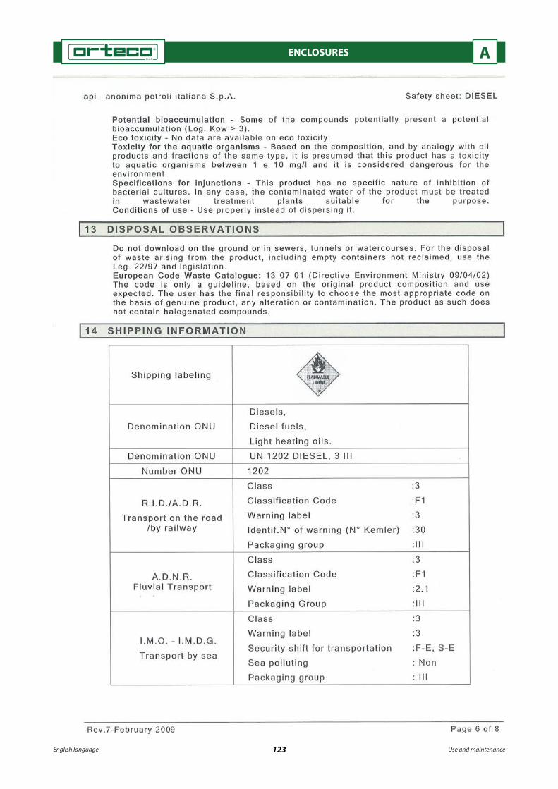
English language 123 Use and maintenance
ENCLOSURES A

English language 124 Use and maintenance
ENCLOSURES A
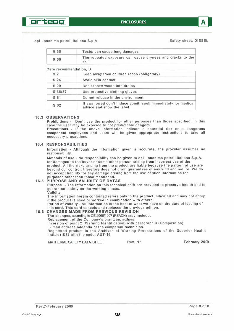
English language 125 Use and maintenance
ENCLOSURES A

English language 126 Use and maintenance
ENCLOSURES A

English language 127 Use and maintenance
ENCLOSURES A
Maintenance sheets after 100 hours of work Date of operation
______/_______/_____
Description of operation
Stamp of the authorised service centre
Signature of the technician
Maintenance sheets after 200 hours of work Date of operation
______/_______/_____
Description of operation
Stamp of the authorised service centre
Signature of the technician
Maintenance sheets after 250 hours of work Date of operation
______/_______/_____
Description of operation
Stamp of the authorised service centre
Signature of the technician
Maintenance register
This register is made up of di�erent maintenance operation sheets; �ll out the sheets after each periodic ordinary and extraordinary maintenance carried out on the machine.
When the sheets have �nished, photocopy one or more pages of the register and keep them together with this manual, to record future maintenance operations.
During maintenance phases carefully follow the safety instructions described herein and the regulations on accident prevention at work.

English language 128 Use and maintenance
ENCLOSURES A
Maintenance sheets after 300 hours of work Date of operation
______/_______/_____
Description of operation
Stamp of the authorised service centre
Signature of the technician
Maintenance sheets after 400 hours of work Date of operation
______/_______/_____
Description of operation
Stamp of the authorised service centre
Signature of the technician
Maintenance sheets after 500 hours of work Date of operation
______/_______/_____
Description of operation
Stamp of the authorised service centre
Signature of the technician
Maintenance sheets after 600 hours of work Date of operation
______/_______/_____
Description of operation
Stamp of the authorised service centre
Signature of the technician

English language 129 Use and maintenance
ENCLOSURES A
Maintenance sheets after 700 hours of work Date of operation
______/_______/_____
Description of operation
Stamp of the authorised service centre
Signature of the technician
Maintenance sheets after 750 hours of work Date of operation
______/_______/_____
Description of operation
Stamp of the authorised service centre
Signature of the technician
Maintenance sheets after 800 hours of work Date of operation
______/_______/_____
Description of operation
Stamp of the authorised service centre
Signature of the technician
Maintenance sheets after 900 hours of work Date of operation
______/_______/_____
Description of operation
Stamp of the authorised service centre
Signature of the technician

English language 130 Use and maintenance
ENCLOSURES A
Maintenance sheets after 1000 hours of work Date of operation
______/_______/_____
Description of operation
Stamp of the authorised service centre
Signature of the technician
Maintenance sheets after 1100 hours of work Date of operation
______/_______/_____
Description of operation
Stamp of the authorised service centre
Signature of the technician
Maintenance sheets after 1200 hours of work Date of operation
______/_______/_____
Description of operation
Stamp of the authorised service centre
Signature of the technician
Maintenance sheets after 1250 hours of work Date of operation
______/_______/_____
Description of operation
Stamp of the authorised service centre
Signature of the technician
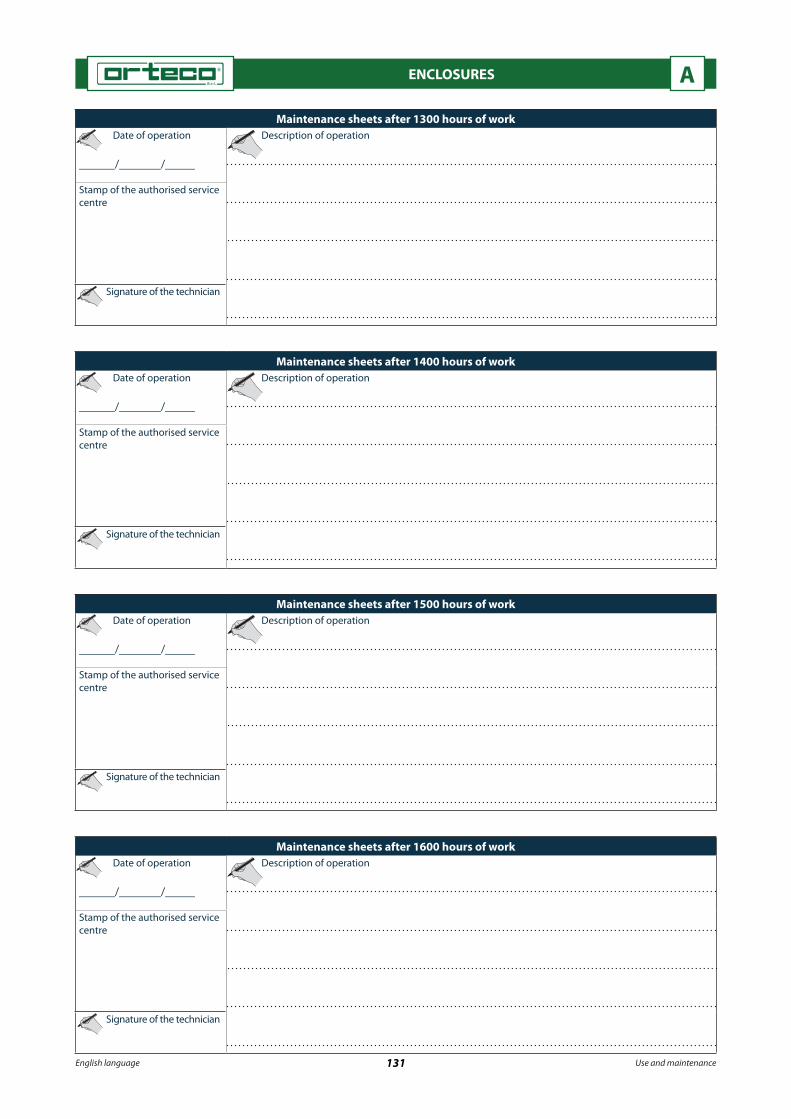
English language 131 Use and maintenance
ENCLOSURES A
Maintenance sheets after 1300 hours of work Date of operation
______/_______/_____
Description of operation
Stamp of the authorised service centre
Signature of the technician
Maintenance sheets after 1400 hours of work Date of operation
______/_______/_____
Description of operation
Stamp of the authorised service centre
Signature of the technician
Maintenance sheets after 1500 hours of work Date of operation
______/_______/_____
Description of operation
Stamp of the authorised service centre
Signature of the technician
Maintenance sheets after 1600 hours of work Date of operation
______/_______/_____
Description of operation
Stamp of the authorised service centre
Signature of the technician

English language 132 Use and maintenance
ENCLOSURES A
Maintenance sheets after 1700 hours of work Date of operation
______/_______/_____
Descrizione intervento
Stamp of the authorised service centre
Signature of the technician
Maintenance sheets after 1750 hours of work Date of operation
______/_______/_____
Descrizione intervento
Stamp of the authorised service centre
Signature of the technician
Maintenance sheets after 1800 hours of work Date of operation
______/_______/_____
Description of operation
Stamp of the authorised service centre
Signature of the technician
Maintenance sheets after 1900 hours of work Date of operation
______/_______/_____
Description of operation
Stamp of the authorised service centre
Signature of the technician

English language 133 Use and maintenance
ENCLOSURES A
Maintenance sheets after 2000 hours of work Date of operation
______/_______/_____
Description of operation
Stamp of the authorised service centre
Signature of the technician