HD 7700 Setup & Operator Manual - Morgana · HD 7700 Setup & Operator Manual Issue 1 December, 01...
31
HD 7700 Setup & Operator Manual Issue 1 December, 01 Performance Design Inc. The Heavy Duty Ultima (HD 7700) electric punch has been designed to punch most any job that may pass through your bindery or office. No matter what type of binding you need to carry out, the HD 7700 can punch the job. It will punch from 25 to 55 sheets on the 11” edge of 20lb bond (80gsm) copy paper with our extra capacity dies or 25-40 sheets with standard dies (The number of sheets depends upon die pattern used). The maximum punching length is a 14” (356 mm) format. Any sheet smaller can be punched for the minimum size. The HD 7700 utilizes quick-change die handles for quick die installations and removal. Extra capacity dies come with the HD 7700 when purchased. HD 7700 Issue 1 Page 1
Transcript of HD 7700 Setup & Operator Manual - Morgana · HD 7700 Setup & Operator Manual Issue 1 December, 01...

HD 7700 Setup & Operator Manual
Issue 1 December, 01 Performance Design Inc.
The Heavy Duty Ultima (HD 7700) electric punch has been designed to punch most any job that may pass through your bindery or office. No matter what type of binding you need to carry out, the HD 7700 can punch the job. It will punch from 25 to 55 sheets on the 11” edge of 20lb bond (80gsm) copy paper with our extra capacity dies or 25-40 sheets with standard dies (The number of sheets depends upon die pattern used). The maximum punching length is a 14” (356 mm) format. Any sheet smaller can be punched for the minimum size. The HD 7700 utilizes quick-change die handles for quick die installations and removal. Extra capacity dies come with the HD 7700 when purchased.
HD 7700 Issue 1 Page 1

Table of Contents
HD 7700 PUNCH Topic: Page Number: 1) Important safety notice 4 2) Placing your machine in the proper location 4 3) Providing power to the machine 4 4) Die installation 5
♦ HD 7700 5 ♦ Extra Capacity Die 5 ♦ Comb Die 5 ♦ Removing punch pins 6 ♦ Die maintenance 7
5) Setting the “Accu-Set” paper stop 7 6) Punching Paper 8
♦ Palm Switch 8 7) Removing paper waste 9 8) Paper Jam 10
Optional Combo Binding Station & Modules
9) Combo Binding Station OD 3500 15 10) Attaching OD 4300 coil Inserter 17 Setup Instructions a) Determine the correct coil size 18 b) Determine the correct size mandrel 18 c) Installing the mandrel on the machine 18 d) Adjusting the mandrel bracket 19 e) Adjusting the paper stop 19 f) Adjusting the front table / lexan guide 19 g) Forward / off / reverse switch 20 h) Inserting a coil 21 i) Drive wheel stop screw 21 j) Cutting a coil 22 11) Attaching OD 4200 Wire Closer 25 Setup Instructions a) Determine the correct wire size 26 b) Inserting the wire into the book 26 c) Setting the closing bar height 27 d) Closing the book 27
HD 7700 Issue 1 Page 2

Topic: Page Number: 12) Attaching OD 4400 Comb Opener 29 Setup Instructions a) Determine the correct comb size 30 b) Placing the comb onto the rake 30 c) Setting the comb opener stop 30 d) Placing the book onto the comb 31 e) Margin settings 31 Setup Illustrations Diagram 1 Punch (Setup) 4 Diagram 2 Punch (Die Installation) 5 Diagram 3 Punch (Pin Removal) 6 Diagram 4 Punch (Paper Guide) 7 Diagram 5 Punch (Punching Paper) 8 Diagram 6 Punch (Chip Drawer) 9 Diagram 7 Punch (Paper Jam) 10 Diagram 8 Combo binding station 15 Diagram 9 Coil inserter 17 Diagram 10a Coil inserter 19 Diagram 10b Coil inserter 20 Diagram 10c Coil inserter 20 Diagram 10d Coil inserter 21 Diagram 10e Coil inserter 22 Diagram 10f Coil inserter 23 Diagram 11 Wire closer 25 Diagram 12a Wire closer 26 Diagram 12b Wire closer 27 Diagram 12c Wire closer 28 Diagram 12d Wire closer 28 Diagram 13 Comb Opener 29 Diagram 14 Comb Opener 31 Troubleshooting HD 7700 13 Troubleshooting Coil Inserter Module 23 Electrical schematic HD 7700 14 Electrical schematic Coil Inserter Module 24 Die list 11 & 12
HD 7700 Issue 1 Page 3
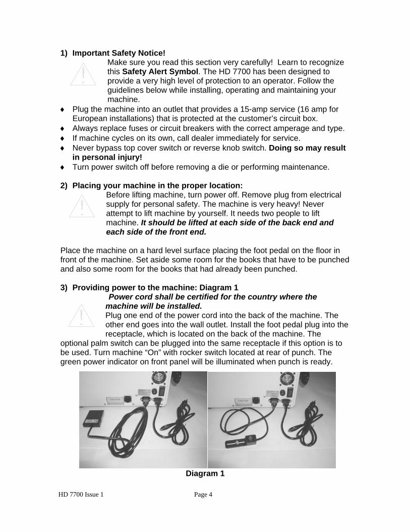
1) Important Safety Notice!
Make sure you read this section very carefully! Learn to recognize this Safety Alert Symbol. The HD 7700 has been designed to provide a very high level of protection to an operator. Follow the guidelines below while installing, operating and maintaining your machine.
♦ Plug the machine into an outlet that provides a 15-amp service (16 amp for European installations) that is protected at the customer’s circuit box.
♦ Always replace fuses or circuit breakers with the correct amperage and type. ♦ If machine cycles on its own, call dealer immediately for service. ♦ Never bypass top cover switch or reverse knob switch. Doing so may result
in personal injury! ♦ Turn power switch off before removing a die or performing maintenance. 2) Placing your machine in the proper location:
Before lifting machine, turn power off. Remove plug from electrical supply for personal safety. The machine is very heavy! Never attempt to lift machine by yourself. It needs two people to lift machine. It should be lifted at each side of the back end and each side of the front end.
Place the machine on a hard level surface placing the foot pedal on the floor in front of the machine. Set aside some room for the books that have to be punched and also some room for the books that had already been punched. 3) Providing power to the machine: Diagram 1
Power cord shall be certified for the country where the machine will be installed. Plug one end of the power cord into the back of the machine. The other end goes into the wall outlet. Install the foot pedal plug into the receptacle, which is located on the back of the machine. The
optional palm switch can be plugged into the same receptacle if this option is to be used. Turn machine “On” with rocker switch located at rear of punch. The green power indicator on front panel will be illuminated when punch is ready.
Diagram 1
HD 7700 Issue 1 Page 4

4) Die installation:
♦ HD 7700 Diagram 2 Make sure the machine is turned off before installing die. Install the die (1) by sliding it into the opening of the machine located on the right-hand side of the machine. Make sure the punch pin retainer assembly (2) slides into the slot of the pusher bar. Push up on both quick-change die handles (3) and lock the die in position. Make sure there is no paper dust in the machine die slot before installing the die. Machine will not operate unless quick-change die handles are in the locked position. Red die clamp indicator will go off, when handles are in the up, locked position.
♦ Extra Capacity Die Extra capacity dies are exactly the same as standard dies with one exception. The opening in the die will accept more paper. These dies are used for high production jobs and can punch from 25 to 55 sheets on the 11” edge of 20 lb. (80gsm) bond copy paper (The number of sheets depends upon die pattern used). Extra capacity dies come with the HD 7700 when purchased.
♦ Comb Die Comb dies are slightly different from the rest of the dies because they have an adjustable backstop. To change the position of the hole placement (margin) to the back edge of the sheet, first install the die into the HD 7700 and secure the die in place. There are four placement positions. Choose the position best suited for your job. Pull or push on the black handle, which is part of the die. Push the handle toward the left for the larger combs and pull it out to the right for smaller combs. The exact position will be left up to the operator’s preference.
Diagram 2 1
2
3
HD 7700 Issue 1 Page 5

♦ Removing Punch Pins: Make sure the machine is turned off before removing the die. To remove a punch pin Diagram 3 from the die, disengage both quick change die handles and slide the die to the right until the die is completely removed from punch.
Step 1. Remove top pin retainer by pushing down first, and then pulling away from bottom pin retainer to expose punch pins.
Step 2. Remove desired punch pin.
Step 3. Place edge of top pin retainer along punch pins and press down while pulling pin retainer back to original position.
Step 4. Install die into machine as described in previous section.
HD 7700 Issue 1 Page 6

♦ Die maintenance: The die will have to be removed before maintenance can be performed. Using the oil provided with the machine, squeeze the plastic bottle over the oil slot that runs the entire length of the die. Too much oil can run onto the paper being punched. After oiling, always punch scrap paper to remove excess oil! 5) Setting the Accu-Set paper stop: Diagram 4 The Accu-Set paper stop should be adjusted so the pointer of the stop lines up with the format and type of die being used. There are two ways to set this stop. The first is a course adjustment to bring the pointer close to the desired setting and the second is a fine micro setting adjustment for exact registration. To set the course adjustment, lift up on the pointer assembly and place the pointer of the assembly close to the format and type hole pattern to be punched. After the pointer is close to the desired setting, turn the fine adjustment knob located on the left side of machine to bring the pointer to the exact setting. Some fine adjustment may be necessary after the first sheet is punched.
Diagram 4
HD 7700 Issue 1 Page 7

6) Punching Paper: Diagram 5 Position the paper that has to be punched either to the left, right or on top of the machine. This is up to the individual operator. Remove some sheets (When punching acetate and heavier stock, punch less sheets) from the pile and slide it down vertically into the opening of the die. When the paper is fully down, slide it to the left so it comes in contact with the paper stop. Make sure all the edges of the sheets are flush by tapping the top and the right hand side of the sheets before pressing the foot pedal or pressing the palm switch. After punching the sheets, place the paper on the punched pile making sure the sheets remain in exact order.
Diagram 5
Use the side of your right hand to activate punch when palm switch is installed.
Diagram 5a
HD 7700 Issue 1 Page 8

7) Removing paper waste: Diagram 6 The paper waste is removed by pulling the paper waste drawer up and toward you. The drawer is located conveniently in the front of the punch. This drawer should be checked frequently. Look through the clear cover while punching and empty prior to filling up and spilling into machine.
Diagram 6
When installing chip drawer back into machine, line up the locating pin on drawer with slot on machine.
Diagram 6a
HD 7700 Issue 1 Page 9

8) Paper Jam: Diagram 7 The HD 7700 uses a circuit board for controlling its cycle and has the ability to automatically reverse the punch pins to their starting position if too much acetate or paper was inserted. There are times when punching too much acetate, the punch pins may not reverse all the way out. Use the procedure described below for manually reversing the machine.
When a paper jam occurs, the circuit breaker or fuse protecting the motor may have to be reset or replaced. This is normal and allows maximum protection for the punch motor.
♦ Locate the reverse knob on the left side of machine. ♦ If the punch stalled before pins were completely through the paper, turn
the reverse knob counterclockwise to reverse punch pins out of paper. ♦ If the punch stalled with the pins all the way through the paper and on its
return stroke, turn the reverse knob clockwise to continue the punch pins to there starting position.
♦ Press the foot pedal or palm switch to see if the machine operates. If yes, continue punching the job. If the machine does not function, see replacing the fuses or resetting circuit breaker in the troubleshooting section of this manual.
Diagram 7
HD 7700 Issue 1 Page 10

5mm
(5mm)
Die list: This is a list of the most common dies manufactured by Performance Design. Special dies are available. Ask your dealer for more information. Drawings are to scale.
HD 7700 Issue 1 Page 11

H 2
D 7700 Issue 1 Page 1
.125, .163, .201, .239
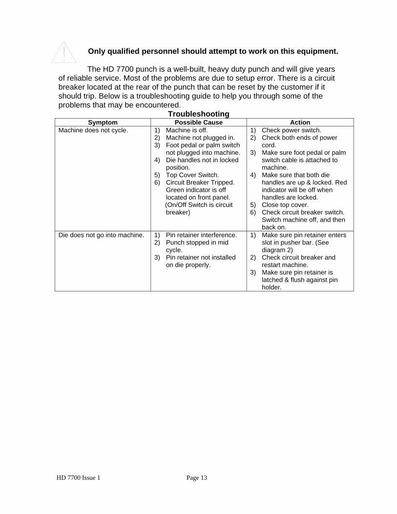
Only qualified personnel should attempt to work on this equipment.
The HD 7700 punch is a well-built, heavy duty punch and will give years
of reliable service. Most of the problems are due to setup error. There is a circuit breaker located at the rear of the punch that can be reset by the customer if it should trip. Below is a troubleshooting guide to help you through some of the problems that may be encountered.
Troubleshooting Symptom Possible Cause Action
Machine does not cycle. 1) Machine is off. 2) Machine not plugged in. 3) Foot pedal or palm switch
not plugged into machine. 4) Die handles not in locked
position. 5) Top Cover Switch. 6) Circuit Breaker Tripped.
Green indicator is off located on front panel.
(On/Off Switch is circuit breaker)
1) Check power switch. 2) Check both ends of power
cord. 3) Make sure foot pedal or palm
switch cable is attached to machine.
4) Make sure that both die handles are up & locked. Red indicator will be off when handles are locked.
5) Close top cover. 6) Check circuit breaker switch.
Switch machine off, and then back on.
Die does not go into machine. 1) Pin retainer interference. 2) Punch stopped in mid
cycle. 3) Pin retainer not installed
on die properly.
1) Make sure pin retainer enters slot in pusher bar. (See diagram 2)
2) Check circuit breaker and restart machine.
3) Make sure pin retainer is latched & flush against pin holder.
HD 7700 Issue 1 Page 13

HD 7700 Electrical Schematic (115 volt AC)
Electrical Shock Hazard
HD 7700 Issue 1 Page 14

9) OD 3500 Combo binding station: Diagram 8 The combo binding station is a base unit that supports three different binding modules. Each module attaches in a matter of minutes. The attachment procedure will be located in the module instructional section of this manual or in the separate manual for the module.
Diagram 8 OD 4300 Coil Inserter The Plastic Spiral inserter will bind books up to 1-1/8” (28.6mm) thick using coil diameter up to 1-1/4” (30mm). The unit attaches to the right side of the Combo binding station using two wing nuts for easy installation.
HD 7700 Issue 1 Page 15

OD 4200 Wire closer The wire closer is capable of binding books up to 1-1/8” (28.6mm) thick. It uses wire sizes from 3/16” to 1-1/4”. It has an adjustable closing bar for the different size wires. Each end can be adjusted independently to obtain a perfect close. The unit attaches to the rear of the Combo binding station using four knobs.
OD 4400 Comb opener The comb opener will bind books up to 2” (51mm) thick. The opener has an adjustable ring opener control for exact book placement. The unit attaches to the rear of the combo binding station using four knobs.
Modules can be purchased separately at any time to be used in conjunction with the OD 3500 combo binding station. Each unit can be installed in five minutes. The coil inserter can be attached and kept on the Combo binding station permanently. If the Wire closer module is installed on the Combo binding station and the Comb opener module is required; the wire closer will have to be removed so that the comb opener can be installed. The opposite is also true. It only takes a few minutes to detach a module and install another.
HD 7700 Issue 1 Page 16

OD 4300 Coil Inserter
10) Installation Instructions: Diagram 9 Procedure to attach the coil inserter onto the combo binding station. Keep all clothing and jewelry away from rotating drive wheel. Power cord shall be certified for the country where the machine will be installed!
♦ Tip the combo binding station on its left side. ♦ Align the two threaded studs (1) that protrude from the coil inserter option
into the two holes located on the right side of the combo binding station. ♦ Use the two wings nuts provided with the coil inserter to attach the unit. Hand
tighten the two wing nuts. ♦ Attach the paper stop bracket (2) to the right side of the combo binding
station using the two black thumb knobs (3) provided. ♦ Attach the paper stop (4) to the paper stop bracket by sliding the square nut
into the slot of the paper stop bracket. This can be positioned and tightened by the knob (5) at a later time when setting the guides to the paper.
♦ Use two black thumb knobs (6) to attach the book table / lexan coil guide to the combo binding station. (The book table / lexan guide has been removed to view the diagram, see diagram 10b to view the book table / lexan guide in position)
♦ Plug one end of the power cord into the back of the coil inserter option and the other end into the wall outlet.
Diagram 9
1
6
45
2 3
HD 7700 Issue 1 Page 17

Setup Instructions: Diagram 10a, 10b, 10c, 10d & 10e a) Determine the correct coil size.
Use a coil that is at least 3/32” (2.5mm) larger than the book thickness for coil sizes up to 3/4” (20mm). After 3/4”, use a coil size of at least 1/8” over the book size. The larger the coil compared to the book, inserting will become much easier.
b) Determine the correct size mandrel.
There are a total of nine mandrels, which are used for coil sizes 3/16” (5mm) up to 1-1/4” (30mm). Use the table below, to choose the correct mandrel size to coil size. Mandrel size Inch Coil size___ mm______ 3/16” 3-16” to 1/4” (5mm-6mm) 1/4” 5/16” (7mm-8mm) 5/16” 3/8” (9mm-10mm) 3/8” 7/16” to 1/2” (11mm-12mm) 1/2” 9/16” (13mm-16mm) 5/8” 3/4” (17mm-19mm) 3/4” 7/8” (20mm-23mm) 7/8” 1” (24mm-27mm) 1” 1-1/8” to 1-1/4” (28mm-30mm)
c) Installing the mandrel on the machine.
Keep all clothing and jewelry away from drive wheel during coil insertion!
♦ Place the mandrel (1) into the mandrel holder bracket (2) making sure the beveled edge of the mandrel is facing the right side of the machine. Both guide pins located on the mandrel need to line up with both slots on the mandrel bracket. Use the black knob (3) to tighten the mandrel in place.
♦ Adjust the height of the mandrel so the center of the mandrel is the same height as the center of the book.
HD 7700 Issue 1 Page 18

d) Adjusting the mandrel bracket.
♦ The mandrel assembly-adjustment knob (4) is located on the right side of the coil inserter. Move the mandrel bracket assembly toward the drive wheel for small mandrels and away from the drive wheel for the larger mandrels.
1
3 2 45
6
Diagram 10a
♦ The mandrel holder bracket-adjustment knob (5) can be adjusted to the left or the right so the leading edge of the coil lines up with the first hole of the book.
e) Adjusting the paper stop. Place the book on top of the combo binding station with the right side of the book against the paper stop bracket. Adjust the paper stop (6) so the holes of the book hang over the edge of the combo binding station. The holes should hang over the edge just enough for the coil to clear the edge of the combo binding station. Tighten the knob located on the paper stop bracket. It may be necessary to fine-tune this after a few books are bound for exact placement.
f) Adjusting the front table / lexan guide.
The front table/ lexan guide (7, 7a & 7b) has two purposes. When the lexan is rotated on top of the coil (7a), it helps assist the coil into the book. Use the lexan guide with all book sizes (thickness) until you notice a problem with the coil slipping on the drive wheel or entering the holes in the book. When the lexan guide (plastic) is in the open position, rotated
HD 7700 Issue 1 Page 19

away from the machine, it acts as a support table (7b) for larger books. For books over 9/16”, it may be necessary at times to split the book in half using the table to support one half of the book, then finish the inserting of the coil. This method improves productivity.
Diagram 10b
7a7b
g) Forward / off / reverse switch.
The forward / off / reverse (8) switch has three positions. The center position of this switch is the off position and should be placed in this position when not using the machine. Press the left side (forward) of the switch and the coil will rotate into the book. Press the right side (reverse) of the switch and the coil will exit the book. The reverse feature allows the coil to be removed from the book. Sometimes this will be necessary when the leading edge of the coil misses a hole of a single sheet.
7
8
Diagram 10c
HD 7700 Issue 1 Page 20

h) Inserting a coil.
Place the coil on the mandrel by sliding the open end of the coil onto the beveled end of the mandrel. Turn the coil so it threads onto the mandrel post (9) and is in front of the drive wheel by one coil. Make sure the forward / reverse switch is in the forward position. Pull the motor handle (10) down to start the motor and engage the drive wheel (11) to the coil. Rotate the coil so it comes close to the edge of the book, but not past the book. With your right hand, hold the leading edge of the coil and thread it though the first two holes of the book. This helps align the holes of the book. Rotate the lexan guide on top of the coil. Pull the handle down gently at first making sure the coil is rotating into the book without missing holes in the sheets or covers. Continue until the coil is past the left side of the book by about one or two coils.
Diagram 10d
9
10
12 11
i) Drive wheel stop screw.
The drive wheel stop screw (12) will prevent the wheel from pressing to hard on the mandrel. It is very important not to have too much pressure on the mandrel when inserting the larger coils. If the leading edge of the coil stops on a misaligned sheet, the coil wants to tie itself into a knot between the book and the end of the mandrel. Setting the stop screw will prevent this from happening most of the time. To set the stop screw, turn it clockwise to push the wheel away from the mandrel. Load the coil onto the mandrel and turn the stop screw counter clockwise while holding down on
HD 7700 Issue 1 Page 21
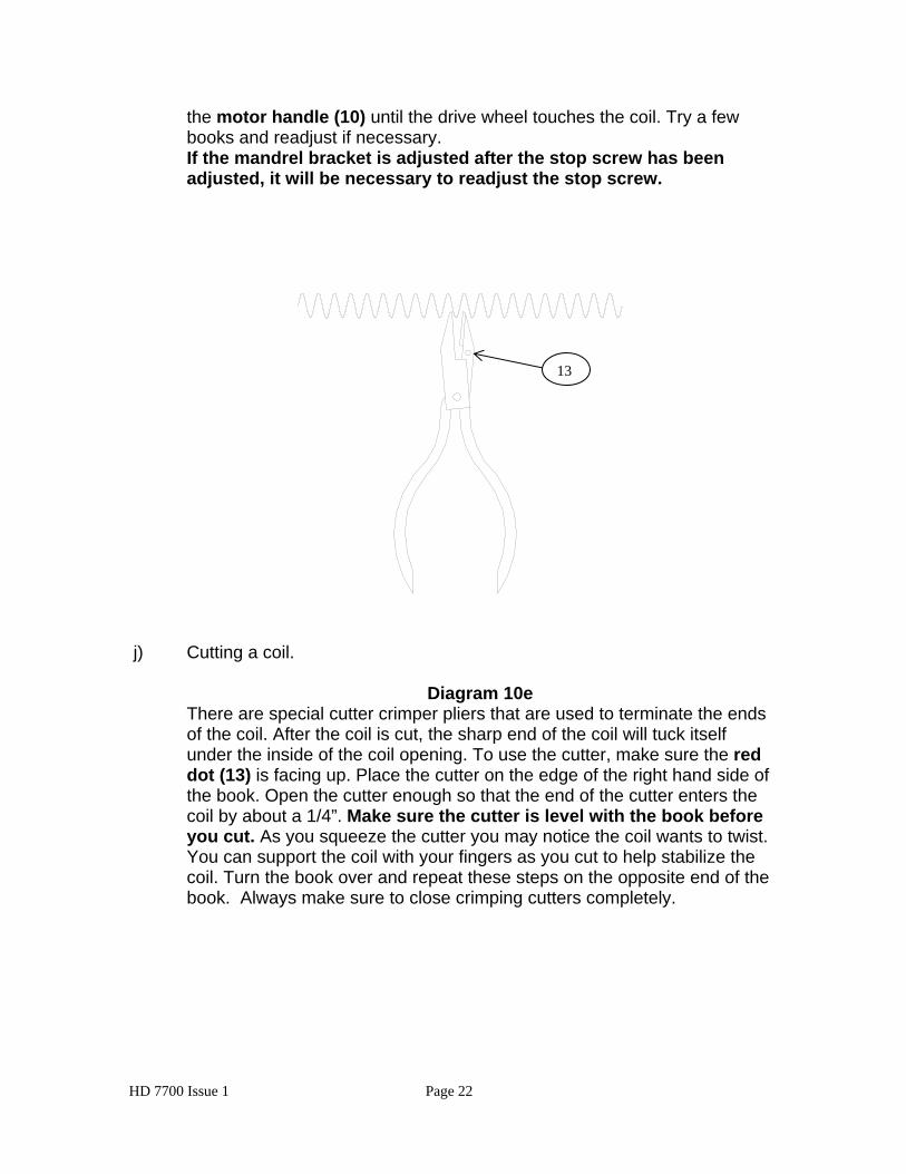
the motor handle (10) until the drive wheel touches the coil. Try a few books and readjust if necessary. If the mandrel bracket is adjusted after the stop screw has been adjusted, it will be necessary to readjust the stop screw.
13
j) Cutting a coil.
Diagram 10e There are special cutter crimper pliers that are used to terminate the ends of the coil. After the coil is cut, the sharp end of the coil will tuck itself under the inside of the coil opening. To use the cutter, make sure the red dot (13) is facing up. Place the cutter on the edge of the right hand side of the book. Open the cutter enough so that the end of the cutter enters the coil by about a 1/4”. Make sure the cutter is level with the book before you cut. As you squeeze the cutter you may notice the coil wants to twist. You can support the coil with your fingers as you cut to help stabilize the coil. Turn the book over and repeat these steps on the opposite end of the book. Always make sure to close crimping cutters completely.
HD 7700 Issue 1 Page 22

Diagram 10f
Only qualified personnel should attempt to work on this equipment. Most of the problems you may encounter are due to setup errors. There is one fuse located at the rear of the OD 4300 inserter that can be replaced by the customer. Below is a troubleshooting guide to help you
through most of the problems that may be encountered.
Troubleshooting Symptom Possible Cause Action
Drive wheel does not rotate. (There is a thermal overload built inside of the motor. Wait several minutes before checking the fuse)
1) Machine is off. (Switch is in center position)
2) Machine not plugged in. 3) Blown Fuse.
1) Place switch in either Forward or Reverse position.
2) Check both ends of power cord.
3) Check Fuse 1. (5amp) Coil tightens on the mandrel when inserting.
1) Mandrel is too small for coil.
1) Select proper size mandrel. (See page 18)
Coil stops before it is completely through the book.
1) The holes in the book are misaligned.
2) The coil is beyond drive wheel.
1) This is normal. Try moving the book around so the coil rotates in the holes.
2) Coil length may need to be longer for that particular book. Note: Larger coils can wind themselves open so the length is actually less.
HD 7700 Issue 1 Page 23

Coil Inserter Module Electrical Schematic (115 volt AC)
Electrical Shock Hazard
NOTE: The motor is protected by a thermal overload located in the motor. It will reset automatically after the motor cools. This product has earned the UL Listing Mark and the UL Listing Mark for Canada. E179574
The OD 4300 has been tested with a duty cycle of 4 seconds on, 15 seconds off with a rest period of 2 minutes after 30 seconds of run time.
HD 7700 Issue 1 Page 24
OD 4200 Wire Closer
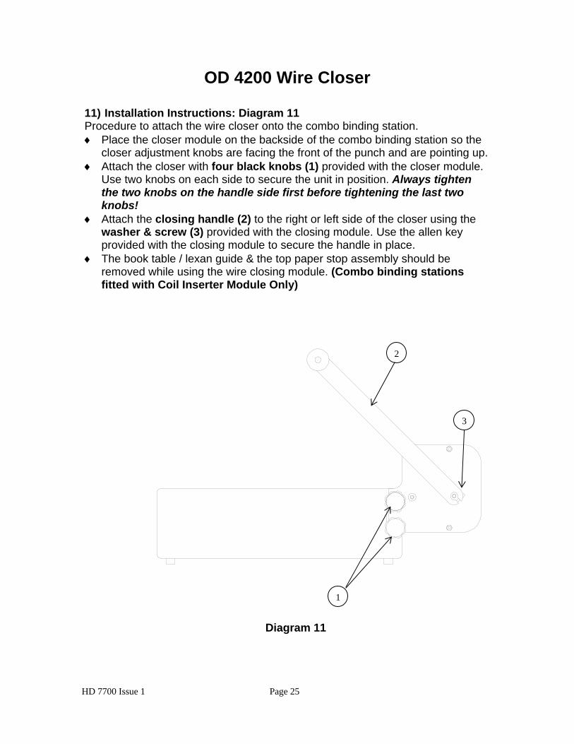
11) Installation Instructions: Diagram 11 Procedure to attach the wire closer onto the combo binding station. ♦ Place the closer module on the backside of the combo binding station so the
closer adjustment knobs are facing the front of the punch and are pointing up. ♦ Attach the closer with four black knobs (1) provided with the closer module.
Use two knobs on each side to secure the unit in position. Always tighten the two knobs on the handle side first before tightening the last two knobs!
♦ Attach the closing handle (2) to the right or left side of the closer using the washer & screw (3) provided with the closing module. Use the allen key provided with the closing module to secure the handle in place.
♦ The book table / lexan guide & the top paper stop assembly should be removed while using the wire closing module. (Combo binding stations fitted with Coil Inserter Module Only)
Diagram 11
3
1
2
HD 7700 Issue 1 Page 25
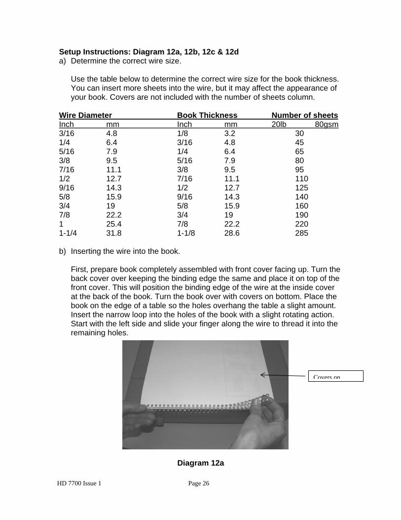
Setup Instructions: Diagram 12a, 12b, 12c & 12d a) Determine the correct wire size.
Use the table below to determine the correct wire size for the book thickness. You can insert more sheets into the wire, but it may affect the appearance of your book. Covers are not included with the number of sheets column.
Wire Diameter Book Thickness Number of sheets Inch mm Inch mm 20lb 80gsm 3/16 4.8 1/8 3.2 30 1/4 6.4 3/16 4.8 45 5/16 7.9 1/4 6.4 65 3/8 9.5 5/16 7.9 80 7/16 11.1 3/8 9.5 95 1/2 12.7 7/16 11.1 110 9/16 14.3 1/2 12.7 125 5/8 15.9 9/16 14.3 140 3/4 19 5/8 15.9 160 7/8 22.2 3/4 19 190 1 25.4 7/8 22.2 220 1-1/4 31.8 1-1/8 28.6 285 b) Inserting the wire into the book.
First, prepare book completely assembled with front cover facing up. Turn the back cover over keeping the binding edge the same and place it on top of the front cover. This will position the binding edge of the wire at the inside cover at the back of the book. Turn the book over with covers on bottom. Place the book on the edge of a table so the holes overhang the table a slight amount. Insert the narrow loop into the holes of the book with a slight rotating action. Start with the left side and slide your finger along the wire to thread it into the remaining holes.
Covers on
Diagram 12a
HD 7700 Issue 1 Page 26

c) Setting the closing bar height.
The closing bar is adjustable on each end allowing the operator to achieve a perfect close at each end of the book. Pull the handle on the closer all the way down and adjust both knobs (3) so the top edge (4) of the closing bar lines up with the line (5) next to the wire size you want to close.
Diagram 12b
3
5 4
d) Closing the book.
With the handle in the full upright position place the book so the open end of the wire is firmly pressed against the back plate (6) inside the closing machine (see diagram 12c on page 28). The narrow loop (7) should be on the top of the book while pushing the book against the back plate. Hold the book as you pull the handle (8) down. Inspect the close and readjust the wire if necessary. When the wire is closed properly, the narrow loop overlaps the wide loop by about 1/32” to 1/16” along the entire length of the book. An indication that the wire is not closed tight enough is when the covers or sheets fall out of the book.
HD 7700 Issue 1 Page 27
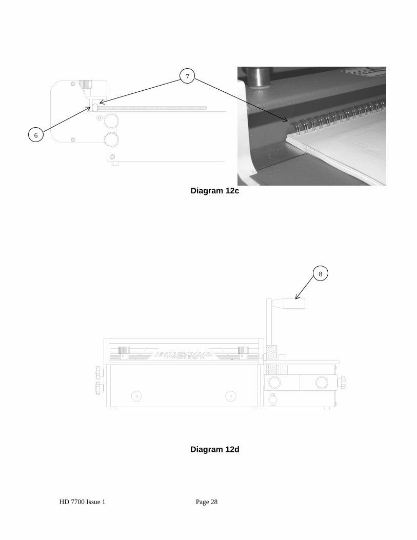
Diagram 12c
Diagram 12d
7
6
8
HD 7700 Issue 1 Page 28

OD 4400 Comb Opener
12) Installation Instructions: Diagram 13 Procedure for attaching the comb opener onto the combo binding station. ♦ Place the comb opener module on the backside of the combo binding station
so the narrow section of the comb opener is facing the front of the combo binding station.
♦ Attach the comb opener with four black knobs (1) provided with the comb opener module. Use two knobs on each side to secure the unit in position. Always tighten the two knobs on the handle side first before tightening the last two knobs!
♦ Attach the comb opener handle (2) to the left or right side of the comb opener using the washer & screw provided with the comb opener module. Use a wrench to secure handle in place.
2
3
4
1
Diagram 13
HD 7700 Issue 1 Page 29
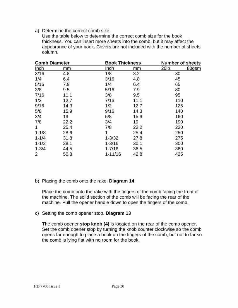
a) Determine the correct comb size.
Use the table below to determine the correct comb size for the book thickness. You can insert more sheets into the comb, but it may affect the appearance of your book. Covers are not included with the number of sheets column.
Comb Diameter Book Thickness Number of sheets Inch mm Inch mm 20lb 80gsm 3/16 4.8 1/8 3.2 30 1/4 6.4 3/16 4.8 45 5/16 7.9 1/4 6.4 65 3/8 9.5 5/16 7.9 80 7/16 11.1 3/8 9.5 95 1/2 12.7 7/16 11.1 110 9/16 14.3 1/2 12.7 125 5/8 15.9 9/16 14.3 140 3/4 19 5/8 15.9 160 7/8 22.2 3/4 19 190 1 25.4 7/8 22.2 220 1-1/8 28.6 1 25.4 250 1-1/4 31.8 1-3/32 27.8 275 1-1/2 38.1 1-3/16 30.1 300 1-3/4 44.5 1-7/16 36.5 360 2 50.8 1-11/16 42.8 425 b) Placing the comb onto the rake. Diagram 14
Place the comb onto the rake with the fingers of the comb facing the front of the machine. The solid section of the comb will be facing the rear of the machine. Pull the opener handle down to open the fingers of the comb.
c) Setting the comb opener stop. Diagram 13
The comb opener stop knob (4) is located on the rear of the comb opener. Set the comb opener stop by turning the knob counter clockwise so the comb opens far enough to place a book on the fingers of the comb, but not to far so the comb is lying flat with no room for the book.
HD 7700 Issue 1 Page 30

COMB OPENEDCOMB ON RAKE BOOK ON COMB
Diagram 14
d) Placing the book onto the comb. Diagram 14
Place the holes of the book on the fingers of the comb. A slight rotating of the book will help guide the holes onto the comb. Return the opener handle to close the comb into the book. The binding process is now complete.
e) Margin setting.
The comb die has an adjustable backstop that allows the hole to edge margin on the paper to vary. Below are the recommended positions for the various size combs. The exact position can be left up to the operator.
1st position is handle pushed all the way to the left.
1ST position Comb sizes 1/4” through 5/16” 2nd position Comb sizes 3/8” through 1/2” 3rd position Comb sizes 9/16” through 3/4” 4th position Comb sizes 7/8” through 2”
Comb dies are the only kind to have an adjustable backstop. To change the position of the hole placement (margin) to the back edge of the sheet, first install the die into the HD 7700 and secure in place. There are four placement positions. Choose the position best suited for your job. Pull or push on the black handle, which is part of the die. Push the handle toward the left for the smaller combs and pull it out to the right for larger combs. The exact position will be left up to the operator’s preference.
HD 7700 Issue 1 Page 31