
HARDWOOD COLLECTION PRICE & SPECIFICATION GUIDE
187
MARCH 2020 HARDWOOD COLLECTION PRICE & SPECIFICATION GUIDE
Transcript of HARDWOOD COLLECTION PRICE & SPECIFICATION GUIDE

MARCH 2020
HARDWOOD COLLECTIONPRICE & SPECIFICATION GUIDE

Index by Description . . . . . . . . . . . . . . . . . . . . . . . . . . . . . . . . . . . . . . .A-CCharacteristics . . . . . . . . . . . . . . . . . . . . . . . . . . . . . . . . . . . . . . . . . . .1Door Styles . . . . . . . . . . . . . . . . . . . . . . . . . . . . . . . . . . . . . . . . . . . . .2-7Finish Availability . . . . . . . . . . . . . . . . . . . . . . . . . . . . . . . . . . . . . . . . .8Premium Color Palette . . . . . . . . . . . . . . . . . . . . . . . . . . . . . . . . . . . . . .812-Step Finishing Process . . . . . . . . . . . . . . . . . . . . . . . . . . . . . . . . . . . .9Humidification/Cabinet Care and Cleaning . . . . . . . . . . . . . . . . . . . . . . . . . .9Construction Features . . . . . . . . . . . . . . . . . . . . . . . . . . . . . . . . . . . . . . .10Modification/Upgrade Compatibility Chart . . . . . . . . . . . . . . . . . . . . . . . . . .11Construction Upgrades . . . . . . . . . . . . . . . . . . . . . . . . . . . . . . . . . . . . . .12Drawer Front Upgrades . . . . . . . . . . . . . . . . . . . . . . . . . . . . . . . . . . . . . .13Non Smart Stop Options . . . . . . . . . . . . . . . . . . . . . . . . . . . . . . . . . . . . .14Custom Modifications . . . . . . . . . . . . . . . . . . . . . . . . . . . . . . . . . . . . . . .15-23Specialty Doors . . . . . . . . . . . . . . . . . . . . . . . . . . . . . . . . . . . . . . . . . .24-25Decorative Glass Inserts . . . . . . . . . . . . . . . . . . . . . . . . . . . . . . . . . . . . .26-27Cabinet Dimensions . . . . . . . . . . . . . . . . . . . . . . . . . . . . . . . . . . . . . . . .28-36Policies & Installer Notes . . . . . . . . . . . . . . . . . . . . . . . . . . . . . . . . . . . . .37Design Checklist . . . . . . . . . . . . . . . . . . . . . . . . . . . . . . . . . . . . . . . . . .38NKBA Guidelines . . . . . . . . . . . . . . . . . . . . . . . . . . . . . . . . . . . . . . . . . .39-40Smart Solutions™ Reference Chart . . . . . . . . . . . . . . . . . . . . . . . . . . . . . . .41Wall Cabinets . . . . . . . . . . . . . . . . . . . . . . . . . . . . . . . . . . . . . . . . . . .42-79Base Cabinets . . . . . . . . . . . . . . . . . . . . . . . . . . . . . . . . . . . . . . . . . . .80-102Universal Access Cabinets . . . . . . . . . . . . . . . . . . . . . . . . . . . . . . . . . . . .103-105Tall Cabinets . . . . . . . . . . . . . . . . . . . . . . . . . . . . . . . . . . . . . . . . . . . .106-125Office & Furniture Cabinets . . . . . . . . . . . . . . . . . . . . . . . . . . . . . . . . . . .126-131Vanity Cabinets . . . . . . . . . . . . . . . . . . . . . . . . . . . . . . . . . . . . . . . . . .132-144Fillers . . . . . . . . . . . . . . . . . . . . . . . . . . . . . . . . . . . . . . . . . . . . . . . .145-147Panels & Skins . . . . . . . . . . . . . . . . . . . . . . . . . . . . . . . . . . . . . . . . . .147-151Moulding . . . . . . . . . . . . . . . . . . . . . . . . . . . . . . . . . . . . . . . . . . . . . .152-155Valances . . . . . . . . . . . . . . . . . . . . . . . . . . . . . . . . . . . . . . . . . . . . . .156Embellishments . . . . . . . . . . . . . . . . . . . . . . . . . . . . . . . . . . . . . . . . . .156-159Lighting . . . . . . . . . . . . . . . . . . . . . . . . . . . . . . . . . . . . . . . . . . . . . . .159Shelves . . . . . . . . . . . . . . . . . . . . . . . . . . . . . . . . . . . . . . . . . . . . . . .160-161Decorative Hardware . . . . . . . . . . . . . . . . . . . . . . . . . . . . . . . . . . . . . . .162-166Accessories . . . . . . . . . . . . . . . . . . . . . . . . . . . . . . . . . . . . . . . . . . . . .167-169Roll Tray Kits . . . . . . . . . . . . . . . . . . . . . . . . . . . . . . . . . . . . . . . . . . . .170Guide Kits and Parts . . . . . . . . . . . . . . . . . . . . . . . . . . . . . . . . . . . . . . .170-171Stain, Paint, & Touch-up Tools . . . . . . . . . . . . . . . . . . . . . . . . . . . . . . . . . .171Hinges . . . . . . . . . . . . . . . . . . . . . . . . . . . . . . . . . . . . . . . . . . . . . . .171Doors, Drawer Fronts, and Drawers . . . . . . . . . . . . . . . . . . . . . . . . . . . . . . .172Parts . . . . . . . . . . . . . . . . . . . . . . . . . . . . . . . . . . . . . . . . . . . . . . . .172Stack Moulding Kits . . . . . . . . . . . . . . . . . . . . . . . . . . . . . . . . . . . . . . . .173-175Painted Hardwood Finish Agreement . . . . . . . . . . . . . . . . . . . . . . . . . . . . . .176Index by Code . . . . . . . . . . . . . . . . . . . . . . . . . . . . . . . . . . . . . . . . . . .177
TABLE OF CONTENTS
TABL
EOF
CONT
ENTS
Effective March 2020
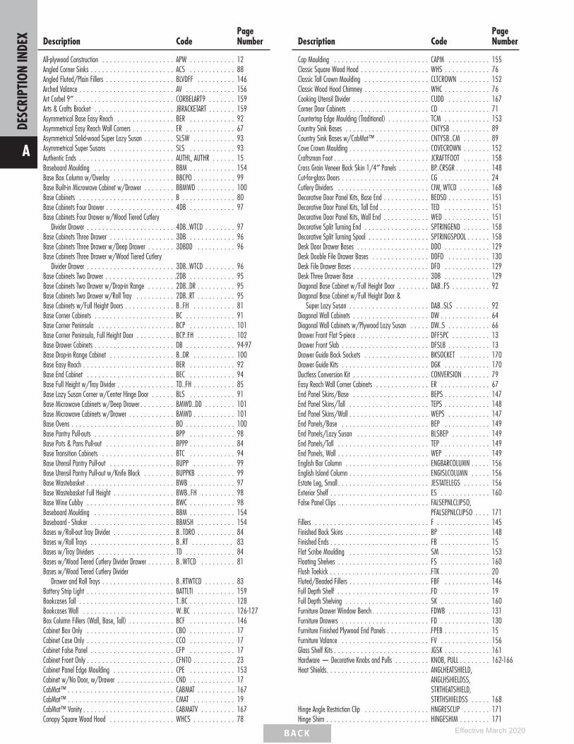
Description CodePageNumber
All-plywood Construction . . . . . . . . . . . . . . . . . . . APW . . . . . . . . . . . . 12Angled Corner Sinks . . . . . . . . . . . . . . . . . . . . . . ACS . . . . . . . . . . . . 88Angled Fluted/Plain Fillers . . . . . . . . . . . . . . . . . . BLVDFF . . . . . . . . . . 146Arched Valance . . . . . . . . . . . . . . . . . . . . . . . . . AV . . . . . . . . . . . . . 156Art Corbel 9″ . . . . . . . . . . . . . . . . . . . . . . . . . . CORBELART9 . . . . . . . 159Arts & Crafts Bracket . . . . . . . . . . . . . . . . . . . . . JBRACKETART . . . . . . . 159Asymmetrical Base Easy Reach . . . . . . . . . . . . . . . BER . . . . . . . . . . . . 92Asymmetrical Easy Reach Wall Corners . . . . . . . . . . . ER . . . . . . . . . . . . . 67Asymmetrical Solid-wood Super Lazy Susan . . . . . . . . SLSW . . . . . . . . . . . 93Asymmetrical Super Susans . . . . . . . . . . . . . . . . . SLS . . . . . . . . . . . . 93Authentic Ends . . . . . . . . . . . . . . . . . . . . . . . . . AUTHL, AUTHR . . . . . . 15Baseboard Moulding . . . . . . . . . . . . . . . . . . . . . BBM . . . . . . . . . . . . 154Base Box Column w/Overlay . . . . . . . . . . . . . . . . BBCPO . . . . . . . . . . . 99Base Built-in Microwave Cabinet w/Drawer . . . . . . . . BBMWD . . . . . . . . . . 100Base Cabinets . . . . . . . . . . . . . . . . . . . . . . . . . B . . . . . . . . . . . . . . 80Base Cabinets Four Drawer . . . . . . . . . . . . . . . . . . 4DB . . . . . . . . . . . . 97Base Cabinets Four Drawer w/Wood Tiered Cutlery
Divider Drawer . . . . . . . . . . . . . . . . . . . . . . . 4DB..WTCD . . . . . . . . 97Base Cabinets Three Drawer . . . . . . . . . . . . . . . . . 3DB . . . . . . . . . . . . 96Base Cabinets Three Drawer w/Deep Drawer . . . . . . . 3DBDD . . . . . . . . . . 96Base Cabinets Three Drawer w/Wood Tiered Cutlery
Divider Drawer . . . . . . . . . . . . . . . . . . . . . . . 3DB..WTCD . . . . . . . . 96Base Cabinets Two Drawer . . . . . . . . . . . . . . . . . . .2DB . . . . . . . . . . . . 95Base Cabinets Two Drawer w/Drop-in Range . . . . . . . 2DB..DR . . . . . . . . . . 95Base Cabinets Two Drawer w/Roll Tray . . . . . . . . . . 2DB..RT . . . . . . . . . . 95Base Cabinets w/Full Height Doors . . . . . . . . . . . . . B..FH . . . . . . . . . . . 81Base Corner Cabinets . . . . . . . . . . . . . . . . . . . . . BC . . . . . . . . . . . . . 91Base Corner Peninsula . . . . . . . . . . . . . . . . . . . . BCP . . . . . . . . . . . . 101Base Corner Peninsula, Full Height Door . . . . . . . . . . BCP..FH . . . . . . . . . . 102Base Drawer Cabinets . . . . . . . . . . . . . . . . . . . . . DB . . . . . . . . . . . . . 94-97Base Drop-in Range Cabinet . . . . . . . . . . . . . . . . . B..DR . . . . . . . . . . . 100Base Easy Reach . . . . . . . . . . . . . . . . . . . . . . . . BER . . . . . . . . . . . . 92Base End Cabinet . . . . . . . . . . . . . . . . . . . . . . . BEC . . . . . . . . . . . . 94Base Full Height w/Tray Divider . . . . . . . . . . . . . . . TD..FH . . . . . . . . . . . 85Base Lazy Susan Corner w/Center Hinge Door . . . . . . BLS . . . . . . . . . . . . 91Base Microwave Cabinets w/Deep Drawer . . . . . . . . . BMWD..DD . . . . . . . . 101Base Microwave Cabinets w/Drawer . . . . . . . . . . . . BMWD . . . . . . . . . . . 101Base Ovens . . . . . . . . . . . . . . . . . . . . . . . . . . . BO . . . . . . . . . . . . . 100Base Pantry Pull-outs . . . . . . . . . . . . . . . . . . . . . BPP . . . . . . . . . . . . 98Base Pots & Pans Pull-out . . . . . . . . . . . . . . . . . . BPPP . . . . . . . . . . . . 84Base Transition Cabinets . . . . . . . . . . . . . . . . . . . BTC . . . . . . . . . . . . 94Base Utensil Pantry Pull-out . . . . . . . . . . . . . . . . . BUPP . . . . . . . . . . . 99Base Utensil Pantry Pull-out w/Knife Block . . . . . . . . BUPPKB . . . . . . . . . . 99Base Wastebasket . . . . . . . . . . . . . . . . . . . . . . . BWB . . . . . . . . . . . . 97Base Wastebasket Full Height . . . . . . . . . . . . . . . . BWB..FH . . . . . . . . . 98Base Wine Cubby . . . . . . . . . . . . . . . . . . . . . . . BWC . . . . . . . . . . . . 98Baseboard Moulding . . . . . . . . . . . . . . . . . . . . . BBM . . . . . . . . . . . . 154Baseboard - Shaker . . . . . . . . . . . . . . . . . . . . . . BBMSH . . . . . . . . . . 154Bases w/Roll-out Tray Divider . . . . . . . . . . . . . . . . B..TDRO . . . . . . . . . . 84Bases w/Roll Trays . . . . . . . . . . . . . . . . . . . . . . B..RT . . . . . . . . . . . 83Bases w/Tray Dividers . . . . . . . . . . . . . . . . . . . . TD . . . . . . . . . . . . . 84Bases w/Wood Tiered Cutlery Divider Drawer . . . . . . . B..WTCD . . . . . . . . . 81Bases w/Wood Tiered Cutlery Divider
Drawer and Roll Trays . . . . . . . . . . . . . . . . . . . B..RTWTCD . . . . . . . . 83Battery Strip Light . . . . . . . . . . . . . . . . . . . . . . . BATTLTI . . . . . . . . . . 159Bookcases Tall . . . . . . . . . . . . . . . . . . . . . . . . . T..BC . . . . . . . . . . . . 128Bookcases Wall . . . . . . . . . . . . . . . . . . . . . . . . W..BC . . . . . . . . . . . 126-127Box Column Fillers (Wall, Base, Tall) . . . . . . . . . . . . BCF . . . . . . . . . . . . 146Cabinet Box Only . . . . . . . . . . . . . . . . . . . . . . . CBO . . . . . . . . . . . . 17Cabinet Case Only . . . . . . . . . . . . . . . . . . . . . . . CCO . . . . . . . . . . . . 17Cabinet False Panel . . . . . . . . . . . . . . . . . . . . . . CFP . . . . . . . . . . . . 17Cabinet Front Only . . . . . . . . . . . . . . . . . . . . . . . CFNTO . . . . . . . . . . . 23Cabinet Panel Edge Moulding . . . . . . . . . . . . . . . . CPE . . . . . . . . . . . . 153Cabinet w/No Door, w/Drawer . . . . . . . . . . . . . . . CND . . . . . . . . . . . . 17CabMat™ . . . . . . . . . . . . . . . . . . . . . . . . . . . . CABMAT . . . . . . . . . . 167CabMat™ . . . . . . . . . . . . . . . . . . . . . . . . . . . . CMAT . . . . . . . . . . . 19CabMat™ Vanity . . . . . . . . . . . . . . . . . . . . . . . . CABMATV . . . . . . . . . 167Canopy Square Wood Hood . . . . . . . . . . . . . . . . . WHCS . . . . . . . . . . . 78
Description CodePageNumber
Cap Moulding . . . . . . . . . . . . . . . . . . . . . . . . . CAPM . . . . . . . . . . . 155Classic Square Wood Hood . . . . . . . . . . . . . . . . . . WHS . . . . . . . . . . . . 76Classic Tall Crown Moulding . . . . . . . . . . . . . . . . . CLTCROWN . . . . . . . . 152Classic Wood Hood Chimney . . . . . . . . . . . . . . . . . WHC . . . . . . . . . . . . 76Cooking Utensil Divider . . . . . . . . . . . . . . . . . . . . CUDD . . . . . . . . . . . 167Corner Door Cabinets . . . . . . . . . . . . . . . . . . . . . CD . . . . . . . . . . . . . 71Countertop Edge Moulding (Traditional) . . . . . . . . . . . TCM . . . . . . . . . . . . 153Country Sink Bases . . . . . . . . . . . . . . . . . . . . . . CNTYSB . . . . . . . . . . 89Country Sink Bases w/CabMat™ . . . . . . . . . . . . . . CNTYSB..CM . . . . . . . 89Cove Crown Moulding . . . . . . . . . . . . . . . . . . . . . COVECROWN . . . . . . . 152Craftsman Foot . . . . . . . . . . . . . . . . . . . . . . . . . JCRAFTFOOT . . . . . . . 158Cross Grain Veneer Back Skin 1/4″ Panels . . . . . . . . BP..CRSGR . . . . . . . . . 148Cut-for-glass Doors . . . . . . . . . . . . . . . . . . . . . . . CG . . . . . . . . . . . . . 24Cutlery Dividers . . . . . . . . . . . . . . . . . . . . . . . . CIW, WTCD . . . . . . . . 168Decorative Door Panel Kits, Base End . . . . . . . . . . . . BEDSD . . . . . . . . . . . 151Decorative Door Panel Kits, Tall End . . . . . . . . . . . . . TED . . . . . . . . . . . . 151Decorative Door Panel Kits, Wall End . . . . . . . . . . . . WED . . . . . . . . . . . . 151Decorative Split Turning End . . . . . . . . . . . . . . . . . SPTRINGEND . . . . . . . 158Decorative Split Turning Spool . . . . . . . . . . . . . . . . SPTRINGSPOOL . . . . . . 158Desk Door Drawer Bases . . . . . . . . . . . . . . . . . . . DDO . . . . . . . . . . . . 129Desk Double File Drawer Bases . . . . . . . . . . . . . . . DDFD . . . . . . . . . . . 130Desk File Drawer Bases . . . . . . . . . . . . . . . . . . . . DFD . . . . . . . . . . . . 129Desk Three Drawer Base . . . . . . . . . . . . . . . . . . . 3DB . . . . . . . . . . . . 129Diagonal Base Cabinet w/Full Height Door . . . . . . . . DAB..FS . . . . . . . . . . 92Diagonal Base Cabinet w/Full Height Door &
Super Lazy Susan . . . . . . . . . . . . . . . . . . . . . DAB..SLS . . . . . . . . . 92Diagonal Wall Cabinets . . . . . . . . . . . . . . . . . . . . DW . . . . . . . . . . . . . 64Diagonal Wall Cabinets w/Plywood Lazy Susan . . . . . DW..S . . . . . . . . . . . 66Drawer Front Flat 5-piece . . . . . . . . . . . . . . . . . . . DFF5PC . . . . . . . . . . 13Drawer Front Slab . . . . . . . . . . . . . . . . . . . . . . . DFSLB . . . . . . . . . . . 13Drawer Guide Back Sockets . . . . . . . . . . . . . . . . . BKSOCKET . . . . . . . . 170Drawer Guide Kits . . . . . . . . . . . . . . . . . . . . . . . DGK . . . . . . . . . . . . 170Ductless Conversion Kit . . . . . . . . . . . . . . . . . . . . CONVERSION . . . . . . . 79Easy Reach Wall Corner Cabinets . . . . . . . . . . . . . . ER . . . . . . . . . . . . . 67End Panel Skins/Base . . . . . . . . . . . . . . . . . . . . BEPS . . . . . . . . . . . . 147End Panel Skins/Tall . . . . . . . . . . . . . . . . . . . . . TEPS . . . . . . . . . . . . 148End Panel Skins/Wall . . . . . . . . . . . . . . . . . . . . . WEPS . . . . . . . . . . . 147End Panels/Base . . . . . . . . . . . . . . . . . . . . . . . BEP . . . . . . . . . . . . 149End Panels/Lazy Susan . . . . . . . . . . . . . . . . . . . BLSBEP . . . . . . . . . . 149End Panels/Tall . . . . . . . . . . . . . . . . . . . . . . . . TEP . . . . . . . . . . . . . 149End Panels, Wall . . . . . . . . . . . . . . . . . . . . . . . . WEP . . . . . . . . . . . . 149English Bar Column . . . . . . . . . . . . . . . . . . . . . . ENGBARCOLUMN . . . . . 156English Island Column . . . . . . . . . . . . . . . . . . . . . ENGISLCOLUMN . . . . . 156Estate Leg, Small . . . . . . . . . . . . . . . . . . . . . . . . JESTATELEGS . . . . . . . 156Exterior Shelf . . . . . . . . . . . . . . . . . . . . . . . . . . ES . . . . . . . . . . . . . 160False Panel Clips . . . . . . . . . . . . . . . . . . . . . . . . FALSEPNLCLIP5O,
PFALSEPNLCLIP5O . . . . 171Fillers . . . . . . . . . . . . . . . . . . . . . . . . . . . . . . F . . . . . . . . . . . . . . 145Finished Back Skins . . . . . . . . . . . . . . . . . . . . . . BP . . . . . . . . . . . . . 148Finished Ends . . . . . . . . . . . . . . . . . . . . . . . . . . FB . . . . . . . . . . . . . 15Flat Scribe Moulding . . . . . . . . . . . . . . . . . . . . . SM . . . . . . . . . . . . . 153Floating Shelves . . . . . . . . . . . . . . . . . . . . . . . . FS . . . . . . . . . . . . . 160Flush Toekick . . . . . . . . . . . . . . . . . . . . . . . . . . .FTK . . . . . . . . . . . . . 20Fluted/Beaded Fillers . . . . . . . . . . . . . . . . . . . . . FBF . . . . . . . . . . . . 146Full Depth Shelf . . . . . . . . . . . . . . . . . . . . . . . . .FD . . . . . . . . . . . . . 19Full Depth Shelving . . . . . . . . . . . . . . . . . . . . . . SK . . . . . . . . . . . . . 160Furniture Drawer Window Bench . . . . . . . . . . . . . . . FDWB . . . . . . . . . . . 131Furniture Drawers . . . . . . . . . . . . . . . . . . . . . . . FD . . . . . . . . . . . . . 130Furniture Finished Plywood End Panels . . . . . . . . . . . .FPEB . . . . . . . . . . . . 15Furniture Valance . . . . . . . . . . . . . . . . . . . . . . . FV . . . . . . . . . . . . . 156Glass Shelf Kits . . . . . . . . . . . . . . . . . . . . . . . . . JGSK . . . . . . . . . . . . 161Hardware — Decorative Knobs and Pulls . . . . . . . . . KNOB, PULL . . . . . . . . 162-166Heat Shields. . . . . . . . . . . . . . . . . . . . . . . . . . . ANGLHEATSHIELD,
ANGLHSHIELDSS,STRTHEATSHIELD,STRTHSHIELDSS . . . . . 168
Hinge Angle Restriction Clip . . . . . . . . . . . . . . . . . HNGRESCLIP . . . . . . . 171Hinge Shim . . . . . . . . . . . . . . . . . . . . . . . . . . . HINGESHIM . . . . . . . . 171
DESC
RIPT
ION
INDE
X
A
Effective March 2020
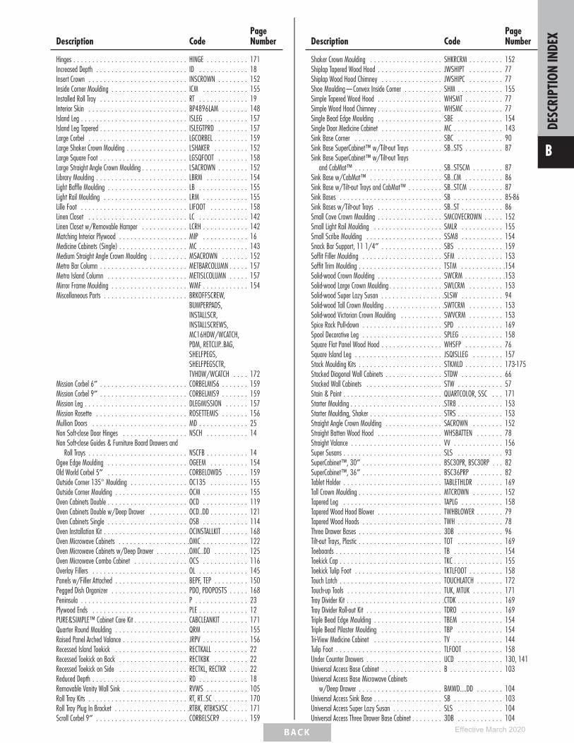
Description CodePageNumber
Hinges . . . . . . . . . . . . . . . . . . . . . . . . . . . . . . HINGE . . . . . . . . . . . 171Increased Depth . . . . . . . . . . . . . . . . . . . . . . . . ID . . . . . . . . . . . . . 18Insert Crown . . . . . . . . . . . . . . . . . . . . . . . . . . INSCROWN . . . . . . . . 152Inside Corner Moulding . . . . . . . . . . . . . . . . . . . . ICM . . . . . . . . . . . . 155Installed Roll Tray . . . . . . . . . . . . . . . . . . . . . . . RT . . . . . . . . . . . . . 19Interior Skin . . . . . . . . . . . . . . . . . . . . . . . . . . BP4896LAM . . . . . . . 148Island Leg . . . . . . . . . . . . . . . . . . . . . . . . . . . . ISLEG . . . . . . . . . . . 157Island Leg Tapered . . . . . . . . . . . . . . . . . . . . . . . ISLEGTPRD . . . . . . . . 157Large Corbel . . . . . . . . . . . . . . . . . . . . . . . . . . LGCORBEL . . . . . . . . . 159Large Shaker Crown Moulding . . . . . . . . . . . . . . . . LSHAKER . . . . . . . . . 152Large Square Foot . . . . . . . . . . . . . . . . . . . . . . . LGSQFOOT . . . . . . . . 158Large Straight Angle Crown Moulding . . . . . . . . . . . . LSACROWN . . . . . . . . 152Library Moulding . . . . . . . . . . . . . . . . . . . . . . . . LBRM . . . . . . . . . . . 154Light Baffle Moulding . . . . . . . . . . . . . . . . . . . . . LB . . . . . . . . . . . . . 155Light Rail Moulding . . . . . . . . . . . . . . . . . . . . . . LRM . . . . . . . . . . . . 155Lille Foot . . . . . . . . . . . . . . . . . . . . . . . . . . . . LIFOOT . . . . . . . . . . 158Linen Closet . . . . . . . . . . . . . . . . . . . . . . . . . . LC . . . . . . . . . . . . . 142Linen Closet w/Removable Hamper . . . . . . . . . . . . LCRH . . . . . . . . . . . . 142Matching Interior Plywood . . . . . . . . . . . . . . . . . . MIP . . . . . . . . . . . . 16Medicine Cabinets (Single) . . . . . . . . . . . . . . . . . . MC . . . . . . . . . . . . . 143Medium Straight Angle Crown Moulding . . . . . . . . . . MSACROWN . . . . . . . 152Metro Bar Column . . . . . . . . . . . . . . . . . . . . . . . METBARCOLUMN . . . . . 157Metro Island Column . . . . . . . . . . . . . . . . . . . . . METISLCOLUMN . . . . . 157Mirror Frame Moulding . . . . . . . . . . . . . . . . . . . . WMF . . . . . . . . . . . . 154Miscellaneous Parts . . . . . . . . . . . . . . . . . . . . . . BRKOFFSCREW,
BUMPERPADS,INSTALLSCR,INSTALLSCREWS,MC16HDW/WCATCH,PDM, RETCLIP..BAG,SHELFPEGS,SHELFPEGSCTR,TVHDW/WCATCH . . . . 172
Mission Corbel 6″ . . . . . . . . . . . . . . . . . . . . . . . CORBELMIS6 . . . . . . . 159Mission Corbel 9″ . . . . . . . . . . . . . . . . . . . . . . . CORBELMIS9 . . . . . . . 159Mission Leg . . . . . . . . . . . . . . . . . . . . . . . . . . . DLEGMISSION . . . . . . 157Mission Rosette . . . . . . . . . . . . . . . . . . . . . . . . ROSETTEMIS . . . . . . . 156Mullion Doors . . . . . . . . . . . . . . . . . . . . . . . . . MD . . . . . . . . . . . . . 25Non Soft-close Door Hinges . . . . . . . . . . . . . . . . . NSCH . . . . . . . . . . . 14Non Soft-close Guides & Furniture Board Drawers and
Roll Trays . . . . . . . . . . . . . . . . . . . . . . . . . . NSCFB . . . . . . . . . . . 14Ogee Edge Moulding . . . . . . . . . . . . . . . . . . . . . OGEEM . . . . . . . . . . 154Old World Corbel 5″ . . . . . . . . . . . . . . . . . . . . . CORBELOWD5 . . . . . . 159Outside Corner 135° Moulding . . . . . . . . . . . . . . . OC135 . . . . . . . . . . 155Outside Corner Moulding . . . . . . . . . . . . . . . . . . . OCM . . . . . . . . . . . . 155Oven Cabinets Double . . . . . . . . . . . . . . . . . . . . . OCD . . . . . . . . . . . . 119Oven Cabinets Double w/Deep Drawer . . . . . . . . . . OCD..DD . . . . . . . . . . 121Oven Cabinets Single . . . . . . . . . . . . . . . . . . . . . OSB . . . . . . . . . . . . 114Oven Installation Kit . . . . . . . . . . . . . . . . . . . . . . OCINSTALLKIT . . . . . . . 168Oven Microwave Cabinets . . . . . . . . . . . . . . . . . . .OMC . . . . . . . . . . . . 122Oven Microwave Cabinets w/Deep Drawer . . . . . . . . .OMC..DD . . . . . . . . . 125Oven Microwave Combo Cabinet . . . . . . . . . . . . . . OCS . . . . . . . . . . . . 116Overlay Fillers . . . . . . . . . . . . . . . . . . . . . . . . . OL . . . . . . . . . . . . . 145Panels w/Filler Attached . . . . . . . . . . . . . . . . . . . BEPF, TEP . . . . . . . . . 150Pegged Dish Organizer . . . . . . . . . . . . . . . . . . . . PDO, PDOPOSTS . . . . . 168Peninsula . . . . . . . . . . . . . . . . . . . . . . . . . . . . P . . . . . . . . . . . . . . 23Plywood Ends . . . . . . . . . . . . . . . . . . . . . . . . . PLE . . . . . . . . . . . . . 12PURE&SIMPLE™ Cabinet Care Kit . . . . . . . . . . . . . . CABCLEANKIT . . . . . . . 171Quarter Round Moulding . . . . . . . . . . . . . . . . . . . QRM . . . . . . . . . . . . 155Raised Panel Arched Valance . . . . . . . . . . . . . . . . . JRPV . . . . . . . . . . . . 156Recessed Island Toekick . . . . . . . . . . . . . . . . . . . RECTKALL . . . . . . . . . 22Recessed Toekick on Back . . . . . . . . . . . . . . . . . . RECTKBK . . . . . . . . . 22Recessed Toekick on Side . . . . . . . . . . . . . . . . . . RECTKL, RECTKR . . . . . 22Reduced Depth . . . . . . . . . . . . . . . . . . . . . . . . . RD . . . . . . . . . . . . . 18Removable Vanity Wall Sink . . . . . . . . . . . . . . . . . RVWS . . . . . . . . . . . 105Roll Tray Kits . . . . . . . . . . . . . . . . . . . . . . . . . . RT, RT..SC . . . . . . . . . 170Roll Tray Plug In Bracket . . . . . . . . . . . . . . . . . . . .RTBK, RTBKSXSC . . . . . 171Scroll Corbel 9″ . . . . . . . . . . . . . . . . . . . . . . . . CORBELSCR9 . . . . . . . 159
Description CodePageNumber
Shaker Crown Moulding . . . . . . . . . . . . . . . . . . . SHKRCRM . . . . . . . . . 152Shiplap Tapered Wood Hood . . . . . . . . . . . . . . . . . JWSHIPT . . . . . . . . . 77Shiplap Wood Hood Chimney . . . . . . . . . . . . . . . . JWSHIPC . . . . . . . . . 77Shoe Moulding—Convex Inside Corner . . . . . . . . . . SHM . . . . . . . . . . . . 155Simple Tapered Wood Hood . . . . . . . . . . . . . . . . . WHSMT . . . . . . . . . . 77Simple Wood Hood Chimney . . . . . . . . . . . . . . . . . WHSMC . . . . . . . . . . 77Single Bead Edge Moulding . . . . . . . . . . . . . . . . . SBE . . . . . . . . . . . . 154Single Door Medicine Cabinet . . . . . . . . . . . . . . . . MC . . . . . . . . . . . . . 143Sink Base Corner . . . . . . . . . . . . . . . . . . . . . . . SBC . . . . . . . . . . . . 90Sink Base SuperCabinet™ w/Tilt-out Trays . . . . . . . . SB..STS . . . . . . . . . . 87Sink Base SuperCabinet™ w/Tilt-out Trays
and CabMat™ . . . . . . . . . . . . . . . . . . . . . . . SB..STSCM . . . . . . . . 87Sink Base w/CabMat™ . . . . . . . . . . . . . . . . . . . SB..CM . . . . . . . . . . 86Sink Base w/Tilt-out Trays and CabMat™ . . . . . . . . . SB..STCM . . . . . . . . . 87Sink Bases . . . . . . . . . . . . . . . . . . . . . . . . . . . SB . . . . . . . . . . . . . 85-86Sink Bases w/Tilt-out Trays . . . . . . . . . . . . . . . . . SB..ST . . . . . . . . . . . 86Small Cove Crown Moulding . . . . . . . . . . . . . . . . . SMCOVECROWN . . . . . 152Small Light Rail Moulding . . . . . . . . . . . . . . . . . . SMLR . . . . . . . . . . . 155Small Scribe Moulding . . . . . . . . . . . . . . . . . . . . SSM8 . . . . . . . . . . . 154Snack Bar Support, 11 1/4″ . . . . . . . . . . . . . . . . SBS . . . . . . . . . . . . 159Soffit Filler Moulding . . . . . . . . . . . . . . . . . . . . . SFM . . . . . . . . . . . . 153Soffit Trim Moulding . . . . . . . . . . . . . . . . . . . . . . TSTM . . . . . . . . . . . .154Solid-wood Crown Moulding . . . . . . . . . . . . . . . . . SWCRM . . . . . . . . . . .153Solid-wood Large Crown Moulding . . . . . . . . . . . . . . SWLCRM . . . . . . . . . 153Solid-wood Super Lazy Susan . . . . . . . . . . . . . . . . .SLSW . . . . . . . . . . . 94Solid-wood Tall Crown Moulding . . . . . . . . . . . . . . . .SWTCRM . . . . . . . . . 153Solid-wood Victorian Crown Moulding . . . . . . . . . . . SWVCRM . . . . . . . . . 153Spice Rack Pull-down . . . . . . . . . . . . . . . . . . . . . SPD . . . . . . . . . . . . 169Spool Decorative Leg . . . . . . . . . . . . . . . . . . . . . SPLEG . . . . . . . . . . . 158Square Flat Panel Wood Hood . . . . . . . . . . . . . . . . WHSFP . . . . . . . . . . 76Square Island Leg . . . . . . . . . . . . . . . . . . . . . . . JSQISLLEG . . . . . . . . 157Stack Moulding Kits . . . . . . . . . . . . . . . . . . . . . . STKMLD . . . . . . . . . . 173-175Stacked Diagonal Wall Cabinets . . . . . . . . . . . . . . . STDW . . . . . . . . . . . 66Stacked Wall Cabinets . . . . . . . . . . . . . . . . . . . . STW . . . . . . . . . . . . 57Stain & Paint . . . . . . . . . . . . . . . . . . . . . . . . . . QUARTCOLOR, SSC . . . 171Starter Moulding . . . . . . . . . . . . . . . . . . . . . . . . .STR8 . . . . . . . . . . . . 153Starter Moulding, Shaker . . . . . . . . . . . . . . . . . . . STRS . . . . . . . . . . . . 153Straight Angle Crown Moulding . . . . . . . . . . . . . . . SACROWN . . . . . . . . 152Straight Batten Wood Hood . . . . . . . . . . . . . . . . . WHSBATTEN . . . . . . . 78Straight Valance . . . . . . . . . . . . . . . . . . . . . . . . VV . . . . . . . . . . . . . 156Super Susans . . . . . . . . . . . . . . . . . . . . . . . . . . SLS . . . . . . . . . . . . 93SuperCabinet™, 30″ . . . . . . . . . . . . . . . . . . . . . BSC30PR, BSC30RP . . . 82SuperCabinet™, 36″ . . . . . . . . . . . . . . . . . . . . . BSC36PRP . . . . . . . . 82Tablet Holder . . . . . . . . . . . . . . . . . . . . . . . . . . TABLETHLDR . . . . . . . 169Tall Crown Moulding . . . . . . . . . . . . . . . . . . . . . . MTCROWN . . . . . . . . 152Tapered Leg . . . . . . . . . . . . . . . . . . . . . . . . . . TAPLG . . . . . . . . . . . 158Tapered Wood Hood Blower . . . . . . . . . . . . . . . . . TWHBLOWER . . . . . . . 79Tapered Wood Hoods . . . . . . . . . . . . . . . . . . . . . TWH . . . . . . . . . . . . 78Three Drawer Bases . . . . . . . . . . . . . . . . . . . . . . 3DB . . . . . . . . . . . . 96Tilt-out Trays, Plastic . . . . . . . . . . . . . . . . . . . . . . TOT . . . . . . . . . . . . 169Toeboards . . . . . . . . . . . . . . . . . . . . . . . . . . . . TB . . . . . . . . . . . . . 154Toekick Cap . . . . . . . . . . . . . . . . . . . . . . . . . . . TKC . . . . . . . . . . . . . 155Toekick Tulip Foot . . . . . . . . . . . . . . . . . . . . . . . TKTLFOOT . . . . . . . . . 158Touch Latch . . . . . . . . . . . . . . . . . . . . . . . . . . . TOUCHLATCH . . . . . . . 172Touch-up Tools . . . . . . . . . . . . . . . . . . . . . . . . . TUK, MTUK . . . . . . . . 171Tray Divider Kit . . . . . . . . . . . . . . . . . . . . . . . . . .CTDK . . . . . . . . . . . . 169Tray Divider Roll-out Kit . . . . . . . . . . . . . . . . . . . . TDRO . . . . . . . . . . . 169Triple Bead Edge Moulding . . . . . . . . . . . . . . . . . . TBEM . . . . . . . . . . . 154Triple Bead Pilaster Moulding . . . . . . . . . . . . . . . . TBP . . . . . . . . . . . . 154Tri-View Medicine Cabinet . . . . . . . . . . . . . . . . . . TV . . . . . . . . . . . . . 144Tulip Foot . . . . . . . . . . . . . . . . . . . . . . . . . . . . TLFOOT . . . . . . . . . . 158Under Counter Drawers . . . . . . . . . . . . . . . . . . . . UCD . . . . . . . . . . . . 130, 141Universal Access Base Cabinet . . . . . . . . . . . . . . . . B . . . . . . . . . . . . . . 103Universal Access Base Microwave Cabinets
w/Deep Drawer . . . . . . . . . . . . . . . . . . . . . . BMWD....DD . . . . . . . 104Universal Access Sink Base . . . . . . . . . . . . . . . . . . SB . . . . . . . . . . . . . 103Universal Access Super Lazy Susan . . . . . . . . . . . . . SLS . . . . . . . . . . . . 104Universal Access Three Drawer Base Cabinet . . . . . . . . 3DB . . . . . . . . . . . . 104
DESC
RIPT
ION
INDE
X
B
Effective March 2020
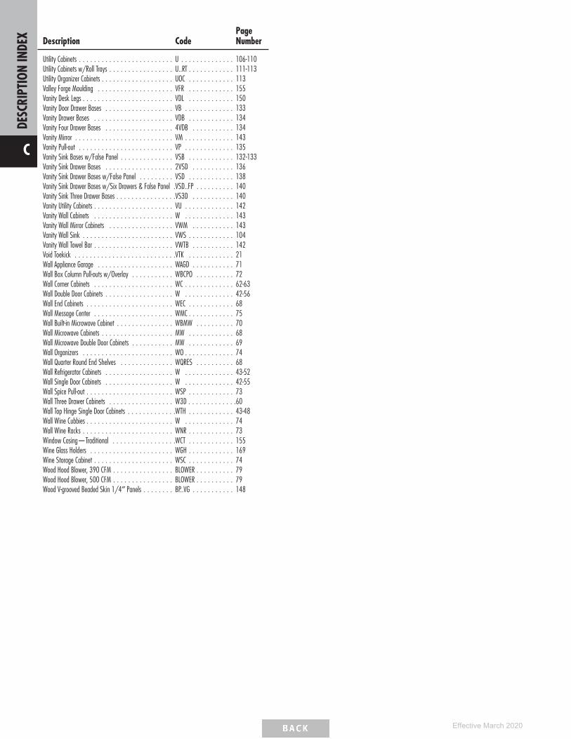
Description CodePageNumber
Utility Cabinets . . . . . . . . . . . . . . . . . . . . . . . . . U . . . . . . . . . . . . . . 106-110Utility Cabinets w/Roll Trays . . . . . . . . . . . . . . . . . U..RT . . . . . . . . . . . . 111-113Utility Organizer Cabinets . . . . . . . . . . . . . . . . . . . UOC . . . . . . . . . . . . 113Valley Forge Moulding . . . . . . . . . . . . . . . . . . . . VFR . . . . . . . . . . . . 155Vanity Desk Legs . . . . . . . . . . . . . . . . . . . . . . . . VDL . . . . . . . . . . . . 150Vanity Door Drawer Bases . . . . . . . . . . . . . . . . . . VB . . . . . . . . . . . . . 133Vanity Drawer Bases . . . . . . . . . . . . . . . . . . . . . VDB . . . . . . . . . . . . 134Vanity Four Drawer Bases . . . . . . . . . . . . . . . . . . 4VDB . . . . . . . . . . . 134Vanity Mirror . . . . . . . . . . . . . . . . . . . . . . . . . . VM . . . . . . . . . . . . . 143Vanity Pull-out . . . . . . . . . . . . . . . . . . . . . . . . . VP . . . . . . . . . . . . . 135Vanity Sink Bases w/False Panel . . . . . . . . . . . . . . VSB . . . . . . . . . . . . 132-133Vanity Sink Drawer Bases . . . . . . . . . . . . . . . . . . 2VSD . . . . . . . . . . . 136Vanity Sink Drawer Bases w/False Panel . . . . . . . . . VSD . . . . . . . . . . . . 138Vanity Sink Drawer Bases w/Six Drawers & False Panel .VSD..FP . . . . . . . . . . 140Vanity Sink Three Drawer Bases . . . . . . . . . . . . . . . .VS3D . . . . . . . . . . . 140Vanity Utility Cabinets . . . . . . . . . . . . . . . . . . . . . VU . . . . . . . . . . . . . 142Vanity Wall Cabinets . . . . . . . . . . . . . . . . . . . . . W . . . . . . . . . . . . . 143Vanity Wall Mirror Cabinets . . . . . . . . . . . . . . . . . VWM . . . . . . . . . . . 143Vanity Wall Sink . . . . . . . . . . . . . . . . . . . . . . . . VWS . . . . . . . . . . . . 104Vanity Wall Towel Bar . . . . . . . . . . . . . . . . . . . . . VWTB . . . . . . . . . . . 142Void Toekick . . . . . . . . . . . . . . . . . . . . . . . . . . .VTK . . . . . . . . . . . . 21Wall Appliance Garage . . . . . . . . . . . . . . . . . . . . WAGD . . . . . . . . . . . 71Wall Box Column Pull-outs w/Overlay . . . . . . . . . . . WBCPO . . . . . . . . . . 72Wall Corner Cabinets . . . . . . . . . . . . . . . . . . . . . WC . . . . . . . . . . . . . 62-63Wall Double Door Cabinets . . . . . . . . . . . . . . . . . . W . . . . . . . . . . . . . 42-56Wall End Cabinets . . . . . . . . . . . . . . . . . . . . . . . WEC . . . . . . . . . . . . 68Wall Message Center . . . . . . . . . . . . . . . . . . . . . WMC . . . . . . . . . . . . 75Wall Built-in Microwave Cabinet . . . . . . . . . . . . . . . WBMW . . . . . . . . . . 70Wall Microwave Cabinets . . . . . . . . . . . . . . . . . . . MW . . . . . . . . . . . . 68Wall Microwave Double Door Cabinets . . . . . . . . . . . MW . . . . . . . . . . . . 69Wall Organizers . . . . . . . . . . . . . . . . . . . . . . . . WO . . . . . . . . . . . . . 74Wall Quarter Round End Shelves . . . . . . . . . . . . . . WQRES . . . . . . . . . . 68Wall Refrigerator Cabinets . . . . . . . . . . . . . . . . . . W . . . . . . . . . . . . . 43-52Wall Single Door Cabinets . . . . . . . . . . . . . . . . . . W . . . . . . . . . . . . . 42-55Wall Spice Pull-out . . . . . . . . . . . . . . . . . . . . . . . WSP . . . . . . . . . . . . 73Wall Three Drawer Cabinets . . . . . . . . . . . . . . . . . W3D . . . . . . . . . . . . .60Wall Top Hinge Single Door Cabinets . . . . . . . . . . . . .WTH . . . . . . . . . . . . 43-48Wall Wine Cubbies . . . . . . . . . . . . . . . . . . . . . . . W . . . . . . . . . . . . . 74Wall Wine Racks . . . . . . . . . . . . . . . . . . . . . . . . WNR . . . . . . . . . . . . 73Window Casing—Traditional . . . . . . . . . . . . . . . . .WCT . . . . . . . . . . . . 155Wine Glass Holders . . . . . . . . . . . . . . . . . . . . . . WGH . . . . . . . . . . . . 169Wine Storage Cabinet . . . . . . . . . . . . . . . . . . . . . WSC . . . . . . . . . . . . 74Wood Hood Blower, 390 CFM . . . . . . . . . . . . . . . . BLOWER . . . . . . . . . . 79Wood Hood Blower, 500 CFM . . . . . . . . . . . . . . . . BLOWER . . . . . . . . . . 79Wood V-grooved Beaded Skin 1/4″ Panels . . . . . . . . BP..VG . . . . . . . . . . . 148
DESC
RIPT
ION
INDE
X
C
Effective March 2020

CHARACTERISTICS OF HARDWOOD
Please keep in mind that no two pieces of wood are exactly the same. Stains are likely to exaggerate grains and other markings in wood.Grain variation and color change should be expected. As hardwood ages, it will darken when exposed to different types of light. Color differencesor changes in wood can also be caused by exposure to harsh chemicals, extreme heat or moisture. Additionally, wood species exhibit otherdefining characteristics, such as mineral deposits/streaks, knots, sap runs, pin holes and wormholes. These markings make the wood unique andcontribute to its enduring beauty.In keeping with our practice of continuous product improvement, Schrock Cabinetry may adjust specifications in design and materials as conditionsrequire. Some components may utilize differing materials to ensure a high-quality product in all applications.
Painted Hardwood finishes combine hardwoods and engineered materials including solid-wood, engineered materials — such as mediumdensity fiberboard (MDF) and high density fiberboard (HDF) — and similar composite materials providing a smoother surface for painting andsuperior stability, consistency, and durability.
Stained Hardwoods -The term "Hardwood" represents a variety of consistent and close-grained wood species. These hardwoods are selectedfor their ability to evenly accept stain when manufacturing cabinetry products.
CHAR
ACTE
RISTIC
SOFH
ARDW
OOD
1
Effective March 2020

Door Style Reference Number Chart
Your Schrock price guide contains charts with prices for each cabinetry product, arranged according to a numerical code. Use the chart below to determine the price code for yourpreferred cabinetry style.
PaintedHardwood
StainedHardwood
Elston 5 5Galvyn 1 1Harwell 4 4Ingalis 3 3Lainey 6 6Lormand 2 2Natcher 4 4Rivali 4 4Willet 3 3
DOOR
STYL
ES
2
Effective March 2020

FULL OVERLAY DOOR STYLES
Elston(page 5)
Ingalis(page 6)
Lainey(page 6)
Rivali(page 7)
Willet(page 7)
PARTIAL OVERLAY DOOR STYLES
Galvyn(page 5)
Harwell(page 5)
Lormand(page 6)
Natcher(page 7) DO
ORST
YLES
3
Effective March 2020

FULL AND PARTIAL OVERLAY SPECIFICATIONS
Full Overlay
1/4”
1/4”
1/4”
1/4”
1/4”1/2”
1/2”
1/2” 1/8”1/4”1/4”
1/4”Wall Cabinet with Butt Doors
UtilityCabinet
BaseCabinet
DrawerBase
Cabinet*
Partial Overlay1/8”
1”
1”
1”
1”
1”
2”
1” 2”
1”2”
Wall with Butt Doors
UtilityCabinet
BaseCabinet
DrawerBase**
1”
*34 1/2″ high application shown. On 32″ high Full Overlay three drawer applications (drawer bases and sink bases with drawers), the reveal above the bottom drawer front is 1/2″.**On Partial Overlay 2DB_ _ (Two Drawer Bases), reveal above the bottom drawer front is 2".• One double door center stile cabinet has the same reveal as two single door cabinets.
DOOR STYLE SPECIFICATIONSAll Door Styles• All doors and drawer fronts are 3/4″ thick unless otherwise noted.
Door and Drawer Front Side Profiles• Veneer and MDF components are shown with gray shading on side profiles. Solid-wood components do not have shading.
Wood Grain• See reference images for wood grain direction on all door styles.
Grain
Grain
Grain
Grain
DOOR
STYL
ES
4
Effective March 2020

DOOR STYLES
ElstonPainted
HardwoodStained
Hardwood
Price Point 5 5
Base Wall
Optional Drawer Front:Flat 5-piece (DFF5PC)
3”
doorprofile
3/4"
drawerfront
profile
3"
drawerfront
profile10"+
21/4"
Top/Bottom
Side
3"
drawerfront
profile
• Flat Center Panel• 3/4″ Thick Door Frame
• Full Overlay• See page 13 for 5-piece drawer front dimensions when specifying decorative hardware.
DecorativeDoor Options
CG MD• •
0.937"0.227"
muntin profile
GalvynPainted
HardwoodStained
Hardwood
Price Point 1 1
Base Wall
21/8"
doorprofile
3/4"
drawerfront
profile
• Flat Center Panel• 3/4″ Thick Door Frame
• Partial Overlay• Profiled Slab Drawer Front
DecorativeDoor Options
CG MD• •
0.660”
0.385”
muntin profile
HarwellPainted
HardwoodStained
Hardwood
Price Point 4 4
Base Wall
21/8"
doorprofile
3/4"
drawerfront
profile
• Raised Center Panel• 3/4″ Thick Door Frame
• Partial Overlay• Profiled Slab Drawer Front
DecorativeDoor Options
CG MD• •
0.660”
0.385”
muntin profile
DOOR
STYL
ES
5
Effective March 2020

DOOR STYLES
IngalisPainted
HardwoodStained
Hardwood
Price Point 3 3
Base Wall
Optional Drawer Front:Flat 5-piece (DFF5PC)
21/4"
doorprofile
3/4"drawerfront
profile
21/4"
optionaldrawerfront
profile
• Flat Center Panel• 3/4″ Thick Door Frame• Full Overlay
• Slab Drawer Front• See page 13 for 5-piece drawer front dimensions when specifying decorative hardware.
DecorativeDoor Options
CG MD• •
0.937"0.227"
muntin profile
LaineyPainted
HardwoodStained
Hardwood
Price Point 6 6
Square Base Square Wall
21/2"
doorprofile 3/4"
drawerfront
profile
• Flat Center Panel• 3/4″ Thick Door Frame
• Full Overlay• Slab Drawer Front
DecorativeDoor Options
CG MD• •
0.314"
0.688"
muntin profile
LormandPainted
HardwoodStained
Hardwood
Price Point 2 2
Base Wall
21/4"
doorprofile
3/4"drawerfront
profile
• Flat Center Panel• 3/4″ Thick Door Frame
• Partial Overlay• Slab Drawer Front
DecorativeDoor Options
CG MD• •
0.937"0.227"
muntin profile
DOOR
STYL
ES
6
Effective March 2020
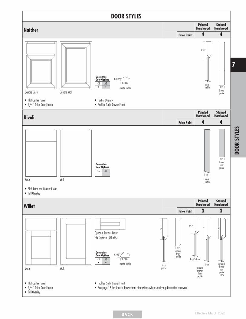
DOOR STYLES
NatcherPainted
HardwoodStained
Hardwood
Price Point 4 4
Square Base Square Wall
21/2"
doorprofile 3/4"
drawerprofile
• Flat Center Panel• 3/4″ Thick Door Frame
• Partial Overlay• Profiled Slab Drawer Front
DecorativeDoor Options
CG MD• •
0.314"
0.688"
muntin profile
RivaliPainted
HardwoodStained
Hardwood
Price Point 4 4
Base Wall
3/4”
doorprofile
3/4”drawerfront
profile
• Slab Door and Drawer Front• Full Overlay
DecorativeDoor Options
CG MD
WilletPainted
HardwoodStained
Hardwood
Price Point 3 3
Base Wall
Optional Drawer Front:Flat 5-piece (DFF5PC)
3"
doorprofile
3/4"drawerfront
profile
3"21/4"
Side
Top/Bottom
optionaldrawerfront
profile
3"
optionaldrawerfront
profile10″+
• Flat Center Panel• 3/4″ Thick Door Frame• Full Overlay
• Profiled Slab Drawer Front• See page 13 for 5-piece drawer front dimensions when specifying decorative hardware.
DecorativeDoor Options
CG MD• •
0.660”
0.385”
muntin profile
DOOR
STYL
ES
7
Effective March 2020

FINISH AVAILABILITY
PAINTED HARDWOOD
Mat
chin
gLa
min
ate
Ends
Elsto
n
Galv
yn
Harw
ell
Inga
lis
Lain
ey
Lorm
and
Natch
er
Riva
li
Will
et
Pain
ts
Cloud ✓ ✓ ✓ ✓ ✓ ✓ ✓ ✓ ✓ ✓
Coconut ✓ ✓ ✓ ✓ ✓ ✓ ✓ ✓ ✓ ✓
Icy Avalanche ✓ ✓ ✓ ✓ ✓ ✓ ✓ ✓ ✓ ✓
Maritime ✓ ✓ ✓ ✓ ✓ ✓ ✓ ✓ ✓ ✓
Moonstone ✓ ✓ ✓ ✓ ✓ ✓ ✓ ✓ ✓ ✓
White ✓ ✓ ✓ ✓ ✓ ✓ ✓ ✓ ✓ ✓
Painted Hardwood finishes combine hardwoods and engineered materials including solid-wood, engineered materials — such as medium density fiberboard (MDF) and high density fiberboard (HDF)— and similar composite materials providing a smoother surface for painting and superior stability, consistency, and durability.
Signed finish agreement required, see pages 176.
STAINED HARDWOOD
Mat
chin
gLa
min
ate
Ends
Elsto
n
Galv
yn
Harw
ell
Inga
lis
Lain
ey
Lorm
and
Natch
er
Riva
li
Will
et
Stai
ns
Buckskin ✓ ✓ ✓ ✓ ✓ ✓ ✓ ✓ ✓ ✓
Chocolate ✓ ✓ ✓ ✓ ✓ ✓ ✓ ✓ ✓ ✓
Colt ✓ ✓ ✓ ✓ ✓ ✓ ✓ ✓ ✓ ✓
Henna ✓ ✓ ✓ ✓ ✓ ✓ ✓ ✓ ✓ ✓
Natural ✓ ✓ ✓ ✓ ✓ ✓ ✓ ✓ ✓ ✓
Sahara ✓ ✓ ✓ ✓ ✓ ✓ ✓ ✓ ✓ ✓
Thatch ✓ ✓ ✓ ✓ ✓ ✓ ✓ ✓ ✓ ✓
PAINTED COLOR PALETTE
OPTIONNAME
DESCRIPTION/LIMITATIONS MATCHINGLAMINATE ENDS
Pain
ts
Cloud Medium gray. ✓
Coconut Creamy off white. ✓
Icy Avalanche Cool white with gray undertones. ✓
Maritime Dark navy with gray/green undertones. ✓
Moonstone Cool dark gray. ✓
White Bright, pure white. ✓
FINI
SHAV
AILA
BILI
TY
8
Effective March 2020

SCHROCK CABINETRY’S 12-STEP FINISHING PROCESS
1. Wood Selection – The selection of the finest woods is the essential first step of the 12-step finishing process.
2. Sanded to Perfection – Our sanding utilizes a fine grit paper, both with and against the wood grain. This process is completed on avacuum table, allowing for a wood surface that is free of dust particles.
3. Achieving Natural Wood Tone – Toner is applied to selected finishes, enhancing the naturalistic wood appearance.
4. Stain Application – A hand-sprayed deep saturating stain is evenly applied to all surfaces for even coverage on all profiles. On multi-stepstains, some non-facing surfaces (such as backs of doors, backs of panels, and matching veneer interiors) may not receive all steps noted. Theresulting finish will be complementary and similar in color and have the same catalyzed top coat and cure, but may not result in the samecolor depth as facing surfaces.
5. Removal of Excess Stain – The wood is hand-wiped to remove excess stain, emphasizing the cabinet’s natural wood grain.
6. Catalyzed Sealer – A tough, clear, catalyzed sealer is hand-sprayed on to protect the grain from moisture.
7. Drying Process – For added durability, the sealed wood is oven cured to lock in the beauty of wood.
8. Hand-Sanded – To achieve an ultra-smooth finish, we hand-sand the material one last time.
9. Dust Removal – The resulting loose dust particles are removed from the surface of the wood.
10. Catalyzed Top Coat – A premium quality catalyzed top coat is applied to protect the wood from environmental elements.
11. Final Top Coat Cure – The top coat is cured for a strong, beautiful finish.
12. Final Inspection – This last inspection is very thorough, ensuring quality and beauty. Our gift to you is that every cabinet is crafted withcare.
CHARACTERISTICS OF PAINT
Paint may develop hairline cracks in the finish, most notable around the joints. This is a result of natural expansion and contraction of thegenuine hardwoods used in the manufacturing of this product. Hairline cracks are not considered a defect in the cabinetry or finish.
HUMIDIFICATION/CABINET CARE AND CLEANING
Humidificationhttps://www.masterbrand.com/humidication
Cabinet Care and Cleaninghttps://www.masterbrand.com/care-and-cleaning
12-S
TEP
FINI
SHIN
GPR
OCES
S
9
Effective March 2020

CONSTRUCTION FEATURESSTANDARD (ECS) PLYWOOD ENDS (ECP)* ALL-PLYWOOD
CONSTRUCTION (ECA)*
Doors & DrawerFronts
See ‘‘Door Styles’’ pages 2-7 for door and drawer front configuration and construction details.
Face Frames 3/4″ solid hardwood.
I-beam Braces 3/8″ furniture board dadoed into face frame, end panels and back panels. 3/8″ plywood dadoed into face frame,end panels and back panels.
Cabinet Sides 1/2″ furniture board with Natural Maple laminate interiors. Exteriors are laminatethat match the color of the face frame.
1/2″ unfinished veneer plywood withNatural Maple interiors.
1/2″ unfinished veneer plywood withNatural Maple interiors.
Cabinet Tops& Bottoms(Wall & Tall)
3/8″ furniture board with natural Maple laminate interior and exterior surfaces. 3/8″ plywood with natural Maplelaminate interior and exterior surfaces.
Cabinet Bottoms(Base & Vanity)
3/8″ furniture board with natural Maple laminate interior surface. 3/8″ plywood with natural Maplelaminate interior surface.
Cabinet Backs 3/8″ furniture board with natural Maple laminate interior. Base cabinets have 3mm system holes for easy drawer and roll trayinstallation.
3/8″ plywood with natural Maplelaminate interior. Base cabinets have3mm system holes for easy drawer androll tray installation.
Adjustable Shelves 3/4″ furniture board with natural Maple laminate to match interiors. Shelves are adjustable in wall and base cabinets unlessotherwise noted.
3/4″ plywood laminated to matchinteriors. Shelves are adjustable in walland base cabinets unless otherwisenoted.
Finish Multi-step finishing process where the finished components are sanded, stained, and sealed before a catalyzed top coat is applied.
Hinges Smart Stop™ fully concealed, integrated cup hinge with self-closing feature; 6-way adjustable. Hinge features deactivation option. Some cabinets utilize a 170° or107° 4-way adjustable hinge. See page 171 for details.
NSCH mod: Fully concealed cup hinge; 6-way adjustable and self-closing.
Drawers Standard: Double fully concealed, ball bearing, self-aligning, full extension guide with Smart Stop self-closing mechanism and fast clip removal system. Smart Stopengages when the drawer is approximately 2″ from closing, applying resistance to the self-closing mechanism. Four-sided clear coated, solid hardwood drawer box withdovetailed construction. All guides have a 75 lb. weight capacity.
NSCFB mod: 1/2″ natural Maple laminated furniture board. Drawer bottom is 3/8″ natural Maple furniture board. Features side-mounted, epoxy coated guides. Allguides have a 75 lb. weight capacity.
Roll Trays Standard: Double fully concealed, ball bearing, self-aligning, full extension guide with Smart Stop self-closing mechanism and fast clip removal system. Smart Stopengages when the drawer is approximately 2″ from closing, applying resistance to the self-closing mechanism. Four-sided clear coated, solid hardwood drawer box withdovetailed construction. All guides have a 75 lb. weight capacity.
NSCFB mod: 1/2″ natural Maple laminated furniture board. Roll tray bottom is 3/8″ natural Maple furniture board. Features side-mounted, epoxy coated guides. Allguides have a 75 lb. weight capacity.
Toekick Unfinished furniture board toekick to allow application of finished toeboard materials. A variety of laminate and wood toeboardskins and baseboard mouldings available in 8′ lengths; see ACCESSORIES section.
3/8″ Unfinished plywood toekick toallow application of finished toeboardmaterials. Toeboard skins and baseboardmouldings available in 8′ lengths; seeACCESSORIES section.
Warranty Schrock has a Limited Lifetime Warranty. For terms and conditions, please visit: https://www.schrock.com/warranty
Interior CabinetComponents
A few interior components are manufactured from laminated furniture board because they provide for the most durable, aesthetic application.
*All-plywood components meet ANSI/HPVA HP-1 standards and may contain MDF or particleboard.
STANDARD BOX CONSTRUCTION STANDARD DRAWER BOX CONSTRUCTIONDrawer Box - Clear Coated Hardwood with Dovetail Corners Drawer Bottom - Plywood
with Natural Maple Laminate, Captured in Box on Four Sides
Drawer Guide - Fully Concealed
Top View
Exterior Sides - 1/2” FurnitureBoard with Matching Laminate
Shelves - 3/4” Furniture Board withNatural Maple Laminate
Tops and Bottoms - 3/8” Furniture Boardwith Natural Maple Laminate
Backs - 3/8” Furniture Boardwith Natural Maple Laminate
Toekicks - Unfinished Furniture Board
Interior Sides - 1/2” Furniture Boardwith Natural Maple Laminate
CONS
TRUC
TION
FEAT
URES
10
Effective March 2020

MODIFICATION/UPGRADE COMPATIBILITY CHART
MODIFICATION/UPGRADE EC
AEC
F5PC
NSCH
NSCF
BAU
THL
AUTH
RFB FP
EBM
IPCB
OCC
OCF
PCN
DID RD CM
ATFD RT AD
DTK
FTK
FTKA
VFT
KFV
RECT
KALL
RECT
KBK
RECT
KLRE
CTKR
VTK
CFNT
OCF
RMO
P CG MD
ConstructionUpgrades(page 12)
ECA - All-plywood Construction ✓ ✓ ✓ ✓ ✓ ✓ ✓ ✓ ✓ ✓ ✓ ✓ ✓ ✓ ✓ ✓ ✓ ✓ ✓ ✓ ✓ ✓ ✓ ✓ ✓ ✓ ✓ ✓
ECP - Plywood Ends ✓ ✓ ✓ ✓ ✓ ✓ ✓ ✓ ✓ ✓ ✓ ✓ ✓ ✓ ✓ ✓ ✓ ✓ ✓ ✓ ✓ ✓ ✓ ✓ ✓
Drawer FrontUpgrades(page 13)
DFF5PC - Drawer Front Flat 5-piece ✓ ✓ ✓ ✓ ✓ ✓ ✓ ✓ ✓ ✓ ✓ ✓ ✓ ✓ ✓ ✓ ✓ ✓ ✓ ✓ ✓ ✓ ✓ ✓ ✓ ✓ ✓ ✓ ✓
Non SmartStopOptions(page 14)
NSCH - Non Soft-close Door Hinges ✓ ✓ ✓ ✓ ✓ ✓ ✓ ✓ ✓ ✓ ✓ ✓ ✓ ✓ ✓ ✓ ✓ ✓ ✓ ✓ ✓ ✓ ✓ ✓ ✓ ✓ ✓ ✓
NSCFB - Non Soft-close Guides &Furniture Board Drawers and RollTrays
✓ ✓ ✓ ✓ ✓ ✓ ✓ ✓ ✓ ✓ ✓ ✓ ✓ ✓ ✓ ✓ ✓ ✓ ✓ ✓ ✓ ✓ ✓ ✓ ✓ ✓
End PanelModifications(page 15)
AUTHL - Authentic End Left ✓ ✓ ✓ ✓ ✓ ✓ ✓ ✓ ✓ ✓ ✓ ✓ ✓ ✓ ✓ ✓ ✓ ✓ ✓ ✓ ✓ ✓ ✓ ✓ ✓ ✓
AUTHR - Authentic End Right ✓ ✓ ✓ ✓ ✓ ✓ ✓ ✓ ✓ ✓ ✓ ✓ ✓ ✓ ✓ ✓ ✓ ✓ ✓ ✓ ✓ ✓ ✓ ✓ ✓ ✓
FB - Finished Ends ✓ ✓ ✓ ✓ ✓ ✓ ✓ ✓ ✓ ✓ ✓ ✓ ✓ ✓ ✓ ✓ ✓ ✓ ✓ ✓ ✓ ✓ ✓ ✓ ✓ ✓
FPEB - Furniture Finished PlywoodEnd Panels
✓ ✓ ✓ ✓ ✓ ✓ ✓ ✓ ✓ ✓ ✓ ✓ ✓ ✓ ✓ ✓ ✓ ✓ ✓ ✓ ✓ ✓ ✓ ✓ ✓ ✓
FinishModification(page 16)
MIP - Matching Interior Plywood ✓ ✓ ✓ ✓ ✓ ✓ ✓ ✓ ✓ ✓ ✓ ✓ ✓ ✓ ✓ ✓ ✓ ✓ ✓ ✓ ✓ ✓ ✓ ✓ ✓ ✓
BoxModifications(pages 17-18)
CBO - Cabinet Box Only ✓ ✓ ✓ ✓ ✓ ✓ ✓ ✓ ✓ ✓ ✓ ✓ ✓ ✓ ✓ ✓ ✓ ✓ ✓ ✓ ✓ ✓ ✓
CCO - Cabinet Case Only ✓ ✓ ✓ ✓ ✓ ✓ ✓ ✓ ✓ ✓ ✓ ✓ ✓ ✓ ✓ ✓ ✓ ✓ ✓
CFP - Cabinet False Panel ✓ ✓ ✓ ✓ ✓ ✓ ✓ ✓ ✓ ✓ ✓ ✓ ✓ ✓ ✓ ✓ ✓ ✓ ✓ ✓ ✓ ✓ ✓ ✓ ✓ ✓
CND - Cabinet with No Door, withDrawer
✓ ✓ ✓ ✓ ✓ ✓ ✓ ✓ ✓ ✓ ✓ ✓ ✓ ✓ ✓ ✓ ✓ ✓ ✓ ✓ ✓ ✓ ✓
ID - Increased Depth ✓ ✓ ✓ ✓ ✓ ✓ ✓ ✓ ✓ ✓ ✓ ✓ ✓ ✓ ✓ ✓ ✓ ✓ ✓ ✓ ✓ ✓ ✓ ✓ ✓
RD - Reduced Depth ✓ ✓ ✓ ✓ ✓ ✓ ✓ ✓ ✓ ✓ ✓ ✓ ✓ ✓ ✓ ✓ ✓ ✓ ✓ ✓ ✓ ✓ ✓ ✓ ✓ ✓ ✓
InstalledInteriorModifications(page 19)
CMAT - CabMat™ ✓ ✓ ✓ ✓ ✓ ✓ ✓ ✓ ✓ ✓ ✓ ✓ ✓ ✓ ✓ ✓ ✓ ✓ ✓ ✓ ✓ ✓
FD - Full Depth Shelf ✓ ✓ ✓ ✓ ✓ ✓ ✓ ✓ ✓ ✓ ✓ ✓ ✓ ✓ ✓ ✓ ✓ ✓ ✓ ✓ ✓ ✓ ✓
RT - Installed Roll Tray ✓ ✓ ✓ ✓ ✓ ✓ ✓ ✓ ✓ ✓ ✓ ✓ ✓ ✓ ✓ ✓ ✓ ✓ ✓ ✓ ✓ ✓
ToekickModifications(pages 20-22)
ADDTK - Add Toekick ✓ ✓ ✓ ✓ ✓ ✓ ✓ ✓ ✓ ✓ ✓ ✓ ✓ ✓ ✓ ✓ ✓ ✓ ✓ ✓ ✓ ✓ ✓ ✓
FTK - Flush Toekick ✓ ✓ ✓ ✓ ✓ ✓ ✓ ✓ ✓ ✓ ✓ ✓ ✓ ✓ ✓ ✓ ✓ ✓ ✓ ✓ ✓ ✓ ✓ ✓
FTKAV - Flush Toekick Arch ✓ ✓ ✓ ✓ ✓ ✓ ✓ ✓ ✓ ✓ ✓ ✓ ✓ ✓ ✓ ✓ ✓ ✓ ✓ ✓ ✓ ✓ ✓ ✓
FTKFV - Flush Toekick Furniture ✓ ✓ ✓ ✓ ✓ ✓ ✓ ✓ ✓ ✓ ✓ ✓ ✓ ✓ ✓ ✓ ✓ ✓ ✓ ✓ ✓ ✓ ✓ ✓
RECTKALL - Recessed IslandToekick
✓ ✓ ✓ ✓ ✓ ✓ ✓ ✓ ✓ ✓ ✓ ✓ ✓ ✓ ✓ ✓ ✓ ✓ ✓
RECTKBK - Recessed Toekick Back ✓ ✓ ✓ ✓ ✓ ✓ ✓ ✓ ✓ ✓ ✓ ✓ ✓ ✓ ✓ ✓ ✓ ✓ ✓ ✓ ✓ ✓ ✓ ✓
RECTKL - Recessed Toekick Left ✓ ✓ ✓ ✓ ✓ ✓ ✓ ✓ ✓ ✓ ✓ ✓ ✓ ✓ ✓ ✓ ✓ ✓ ✓ ✓ ✓ ✓ ✓
RECTKR - Recessed Toekick Right ✓ ✓ ✓ ✓ ✓ ✓ ✓ ✓ ✓ ✓ ✓ ✓ ✓ ✓ ✓ ✓ ✓ ✓ ✓ ✓ ✓ ✓ ✓
VTK - Void Toekick ✓ ✓ ✓ ✓ ✓ ✓ ✓ ✓ ✓ ✓ ✓ ✓ ✓ ✓ ✓ ✓ ✓ ✓ ✓ ✓
ConfigurationModifications(page 23-24)
CFNTO - Cabinet Front Only ✓ ✓ ✓ ✓ ✓ ✓ ✓
CFRMO - Cabinet Frame Only ✓ ✓ ✓
P - Peninsula ✓ ✓ ✓ ✓ ✓ ✓ ✓ ✓ ✓ ✓ ✓ ✓ ✓ ✓ ✓ ✓ ✓ ✓ ✓ ✓ ✓ ✓ ✓ ✓ ✓
SpecialtyDoors(pages 25-26)
CG - Cut-for-glass ✓ ✓ ✓ ✓ ✓ ✓ ✓ ✓ ✓ ✓ ✓ ✓ ✓ ✓ ✓
MD - Mullion Door ✓ ✓ ✓ ✓ ✓ ✓ ✓ ✓ ✓ ✓ ✓ ✓ ✓ ✓ ✓
Orders for cabinets with non-compatible modifications will not be processed. Please contact customer service for more details.✓Represents compatible modification(s) and upgrade(s).
MOD
IFIC
ATIO
N/UP
GRAD
ECO
MPA
TIBI
LITY
CHAR
T
11
Effective March 2020

CONSTRUCTION UPGRADESSee page 11 for modification compatibility. Each modification will be priced accordingly.
OPTIONNAME
APPLICABLECABINET GROUP DESCRIPTION/LIMITATIONS PRICING
All-plywoodConstruction(ECA)*
Most cabinets with sides Replaces standard cabinet construction with plywood for1/2″ ends, 3/8″ top, bottom, back, and 3/4″ shelves.Exterior of the cabinet ends are unfinished.
Cabinet list + 10%
Shelf kits Replaces standard shelf construction with 3/4″ laminatedplywood shelves.
Shelves: List + 10%
Plywood Ends(ECP)*
Most cabinets with sides Replaces standard cabinet ends with unfinished 1/2″plywood exterior ends.
Cabinet list + 5%
ALL-PLYWOOD CONSTRUCTION (ECA)*Backs - 3/8" Plywood with Natural Maple Laminate
Exterior Sides - 1/2" Unfinished Plywood with Veneer
Toekicks - Unfinished Plywood
Shelves - 3/4" Plywood with Natural Maple Laminate
Interior Sides - 1/2" Plywood with Natural Maple Laminate
Tops and Bottoms - 3/8" Plywood with Natural Maple Laminate
Top View
PLYWOOD ENDS (ECP)*
Top View
Exterior Sides - 1/2" Unfinished Plywood with Veneer
Shelves - 3/4" Furniture Board with Natural Maple Laminate
Interior Sides - 1/2" Plywood with Natural Maple Laminate
Toekicks - Unfinished Furniture Board
Tops and Bottoms - 3/8" Furniture Board with Natural Maple Laminate
Backs - 3/8" Furniture Board with Natural Maple Laminate
*All-plywood components meet ANSI/HPVA HP-1 standards and may contain MDF or particleboard.
CONS
TRUC
TION
UPGR
ADES
12
Effective March 2020

DRAWER FRONT UPGRADESSee page 11 for modification compatibility. Each modification will be priced accordingly.
OPTIONNAME
APPLICABLECABINET GROUP DESCRIPTION/LIMITATIONS PRICING
Drawer Front Flat5-piece(DFF5PC)
Base, tall, and vanity cabinetson Elston, Ingalis, and Willet
Replaces the standard drawer front with a 5-piece drawer front (see images with applicable doorstyles). Must upgrade all drawer fronts on a cabinet where applicable.
Premium finish upcharges will apply where applicable.
See below for 5-piece drawer front dimensions when specifying decorative hardware.
$102 list per drawer
DRAWER FRONT FLAT 5-PIECE (DFF5PC)
Elston Ingalis Willet
5-PIECE DRAWER FRONT DIMENSIONS CHART
5-PIECE DRAWER FRONTS DRAWER FRONT WIDTH DRAWER FRONT HEIGHT PANEL FLAT WIDTH PANEL FLAT HEIGHTElston 8 1/2″ 6 1/4″ 2 1/2″ 1 3/4″Ingalis 8 1/2″ 6 1/4″ 4″ 1 3/4″Willet 8 1/2″ 6 1/4″ 2 1/2″ 1 3/4″Drawer front sizes are representative of a 9″ wide base cabinet.
DRAW
ERFR
ONT
UPGR
ADES
13
Effective March 2020

NON SMART STOP OPTIONSSee page 11 for modification compatibility. Each modification will be priced accordingly.
OPTIONNAME
APPLICABLECABINET GROUP DESCRIPTION/LIMITATIONS PRICING
Non Soft-closeDoor Hinges(NSCH)
Most cabinets with doors Replaces Smart Stop hinges with fully concealed cuphinge; 6-way adjustable and self-closing.
Deduct $4 list per door
Non Soft-closeGuides & FurnitureBoard Drawers andRoll Trays(NSCFB)
Most cabinets with drawers and/or roll trays Replaces drawers and roll trays with 1/2″ natural Maplelaminated furniture board. Drawer bottom is 3/8″ naturalMaple furniture board.Replaces Smart Stop guides with side-mounted, epoxycoated guides. All guides have a 75 lb. weight capacity.
Deduct $32 list per drawer or roll tray
NON SOFT-CLOSE DOOR HINGES (NSCH)
NON SOFT-CLOSE GUIDES & FURNITURE BOARD DRAWERS AND ROLL TRAYS (NSCFB)
Drawer Box / Roll Tray1/2” Furniture Board with Natural Maple Laminate
Drawer / Roll Tray Bottom3/8” Furniture Board with Natural Maple Laminate
Drawer GuideSide-mounted
NON
SMAR
TST
OPOP
TION
S
14
Effective March 2020

END PANEL MODIFICATIONSSee page 11 for modification compatibility. Each modification will be priced accordingly.
OPTIONNAME
APPLICABLECABINET GROUP DESCRIPTION/LIMITATIONS PRICING
Authentic Ends(AUTHL)(AUTHR)
Most wall, base, tall, andvanity cabinets
Modifies cabinet end panel(s) with applied decorative door(s) onto FPEB upgraded end panel(s).
Includes FPEB modification—If AUTHL or AUTHR upgrades are specified, the opposite end panel isalso FPEB.
Available on most cabinets with depths of 12″, 15″, 18″, 21″, and 24″.
12″ and 15″ high wall cabinets will have double door configuration on 21″ and 24″ deepapplications.
For tall cabinets, non-miter doors have two panels on the bottom door.
Office base cabinets (29″ high) will have double door configuration when specified on 24″ deepcabinets.
Wall: $374 list per sideBase & Vanity: $530 list per sideTall: $1,265 list per side
Finished Ends(FB)
Cabinets with ECA or ECPmodification; both ends willbe finished
Creates a matching finished 1/2″ veneer plywood exterior. Wall: $74 listBase: $121 listTall: $307 list
Furniture FinishedPlywood EndPanels(FPEB)*
Most wall, base, tall, office,and vanity cabinets
Replaces standard cabinet ends with 3/4″ finished veneer end panels to achieve a Furniture Endappearance. Both exterior sides are finished. Matching interior (MIP) is available.
Wall: $165 listBase & Vanity: $229 listTall: $395 list
AUTHENTIC ENDS (AUTHL/AUTHR)
Wall cabinets Base and Vanity cabinets
FURNITURE FINISHED PLYWOOD ENDPANELS CONSTRUCTION UPGRADE (FPEB)*
Top View
Exterior Sides - 3/4” Plywoodwith Veneer
Shelves - 3/4” Furniture Board withNatural Maple Laminate
Interior Sides - 3/4” Plywood withNatural Maple Laminate
Toekicks - Unfinished Furniture Board
Tops and Bottoms - 3/8” Furniture Boardwith Natural Maple Laminate
Backs - 3/8” Furniture Boardwith Natural Maple Laminate
*All-plywood components meet ANSI/HPVA HP-1 standards and may contain MDF or particleboard.
END
PANE
LMOD
IFIC
ATIO
NS
15
Effective March 2020
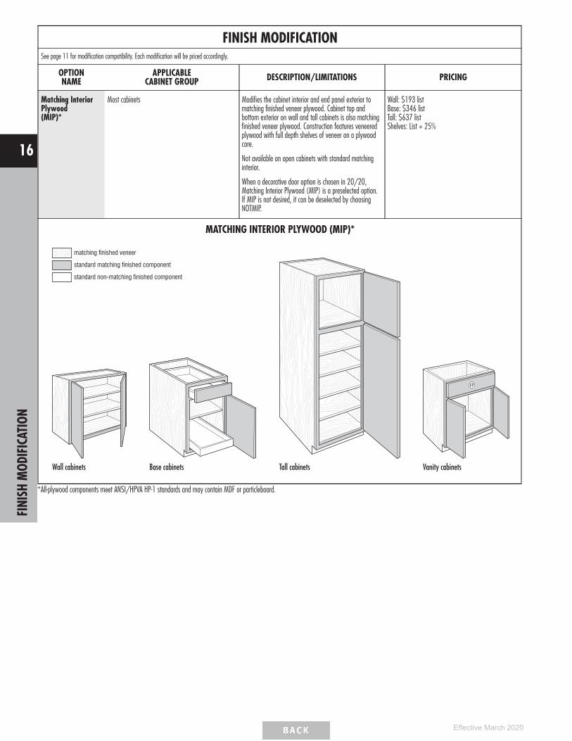
FINISH MODIFICATIONSee page 11 for modification compatibility. Each modification will be priced accordingly.
OPTIONNAME
APPLICABLECABINET GROUP DESCRIPTION/LIMITATIONS PRICING
Matching InteriorPlywood(MIP)*
Most cabinets Modifies the cabinet interior and end panel exterior tomatching finished veneer plywood. Cabinet top andbottom exterior on wall and tall cabinets is also matchingfinished veneer plywood. Construction features veneeredplywood with full depth shelves of veneer on a plywoodcore.
Not available on open cabinets with standard matchinginterior.
When a decorative door option is chosen in 20/20,Matching Interior Plywood (MIP) is a preselected option.If MIP is not desired, it can be deselected by choosingNOTMIP.
Wall: $193 listBase: $346 listTall: $637 listShelves: List + 25%
MATCHING INTERIOR PLYWOOD (MIP)*
matching finished veneer
standard matching finished component
standard non-matching finished component
Wall cabinets Base cabinets Tall cabinets
FP
Vanity cabinets
*All-plywood components meet ANSI/HPVA HP-1 standards and may contain MDF or particleboard.
FINI
SHM
ODIF
ICAT
ION
16
Effective March 2020

BOX MODIFICATIONSSee page 11 for modification compatibility. Each modification will be priced accordingly.
OPTIONNAME
APPLICABLECABINET GROUP DESCRIPTION/LIMITATIONS PRICING
Cabinet Box Only(CBO)
Most wall, base, tall, and vanity cabinets Removes doors, drawer fronts, and any accessory itemsattached to a door or drawer front. Drawer box and anyinterior components attached to the cabinet box will beincluded. Frames will not be drilled for hinges.
Cabinets without drawers: 85% of cabinet listCabinets with drawers: 90% of cabinet list
Cabinet Case Only(CCO)
Most wall, base, tall, and vanity cabinets Removes doors, drawer fronts, drawers, and interiorcomponents. Frames will not be drilled for hinges, butcabinets will have standard drilling for shelves and guides.
85% of cabinet list
Cabinet False Panel(CFP)
Most base and vanity cabinets with a top drawer Replaces top drawer with false panel. Not available withdeep drawers.
No Upcharge
Cabinet with NoDoor, with Drawer(CND)
Most wall, base, tall, and vanity cabinets withdoor(s) and drawer(s)
Removes door(s). Complete drawer(s) with drawerfront(s) and interior components remain in cabinet.Frames will not be drilled for hinges.
90% of cabinet list
CABINET BOX ONLY (CBO)
Cabinets less doors − Tall
Cabinets less doors − Wall
Cabinets less doors and drawer fronts − Base
CABINET CASE ONLY (CCO)
Cabinet case only − Tall
Cabinet case only − Wall
Cabinet case only − Base
CABINET FALSE PANEL (CFP)
FP
Base and Vanity cabinets
CABINET WITH NO DOOR, WITH DRAWER (CND)
Base and Vanity cabinets
BOX
MOD
IFIC
ATIO
NS
17
Effective March 2020

BOX MODIFICATIONS (cont’d)See page 11 for modification compatibility. Each modification will be priced accordingly.
OPTIONNAME
APPLICABLECABINET GROUP DESCRIPTION/LIMITATIONS PRICING
IncreasedDepth(ID)
Most wall, tall, and vanitycabinets with a frame
Increases the depth of wall and vanity cabinets in 3″ increments to a maximum depth of 24″.
Increased depth wall cabinets should be either floor mounted or stacked to maintain stability.
Shelf depths are increased on cabinets with increased depth.
Wall Peninsula cabinets may be increased in 3″ increments to 18″ maximum.
Wall: $284 listTall: $392 listVanity: $342 list
End panels Increases the depth in 3″ increments to a maximum depth of 30″. List + 40%
Box column fillers Increases the depth in 3″ increments to a maximum depth of 27″. List + 40%
ReducedDepth(RD)
Most base, tall, and vanitycabinets with drawers or rolltrays
Reduces the depth in 3″ increments to a minimum of 18″. Any specified shelving is included and isalways full depth. The dimension is specified as the distance from the front of the face frame to theback of the cabinet.
Most base, tall, and vanitycabinets without drawers orroll trays
Reduces the depth in 3″ increments to a minimum depth of 12″.Any specified shelving is included and is always full depth.The dimension is specified as the distance from the front of the face frame to the back of thecabinet.
Wall: $284 listBase: $342 listTall: $392 listVanity: $342 list (RD18 no charge)
Most wall cabinets Reduces the depth in 3″ increments to a minimum depth of 6″.Any specified shelving is included and is always full depth.The dimension is specified as the distance from the front of the face frame to the back of thecabinet.
End panels, shelves, and boxcolumn fillers
Reduces the depth in 3″ increments to a minimum depth of 6″.
List + 30%Roll tray kits Reduces the depth in 3″ increments to fit a minimum cabinet depth of 18″.
Drawer Box and Roll Tray Exterior Depth Clearance Behind Drawer Box or Roll Tray and Back Panel
Cabinet Depth Standard Guides NSCFB GuidesHeavy Duty Side-mount Guides
(DDFD) Standard Guides NSCFB GuidesHeavy Duty Side-mount Guides
(DDFD)
24″ 21″ 21″ 21″ 2 3/4″ 2 3/4″ 2 3/4″21″ 18″ 18″, 15″ for roll trays 18″ 2 3/4″ 2 3/4″ 2 3/4″18″ 15″ 15″ N/A 2 3/4″ 2 3/4″ N/A
INCREASED DEPTH (ID)
Wall cabinets
FP
Vanity cabinets
REDUCED DEPTH (RD)
Wall cabinets Base cabinetsBOX
MOD
IFIC
ATIO
NS
18
Effective March 2020

INSTALLED INTERIOR MODIFICATIONSSee page 11 for modification compatibility. Each modification will be priced accordingly.
OPTIONNAME
APPLICABLECABINET GROUP DESCRIPTION/LIMITATIONS PRICING
CabMat™
(CMAT1)Most base and vanity cabinets Installs removable CabMat™, size is determined by face frame opening width and cabinet
depth.
Not available with Reduced Depth modification. When ordered with Increased Depthmodification, CabMat™ size does not change.
Vanity cabinets with face frame openings of 24″ and 30″ will utilize CabMat™ sized for 21″and 27″ openings.
See page 167 for CabMat™ product descriptions.
CMAT1: Cabinet list + $276
Full Depth Shelf(FD)
Base cabinets with standardhalf depth shelves
Replaces standard shelf with full depth shelf. $64 list per cabinet
Installed Roll Tray(RT)
Select base, tall, office, andvanity cabinets
Installs specified number of roll trays (1-5). Example, for two roll trays, specify 2RT.
When 1RT is specified on a base cabinet, the roll tray is installed in the lowest position andone half-depth adjustable shelf is included.
On utility cabinets for the lower section, 1RT includes three shelves, 2RT includes two shelves,and 3RT includes 1 shelf. No shelves for lower section are included with 4RT or 5RT.
See page 30 for RT positions.
1RT: Cabinet list + $2192RT: Cabinet list + $4403RT: Cabinet list + $6594RT: Cabinet list + $8795RT: Cabinet list + $1,098
Installed Roll TrayBoth(RTB)
Select base and vanitycabinets with center stile
On cabinets with center stile, installs a roll tray on both sides of the cabinet.1RTB - 2 roll trays2RTB - 4 roll trays3RTB - 6 roll trays4RTB - 8 roll trays
1RTB: Cabinet list + $4382RTB: Cabinet list + $8803RTB: Cabinet list + $13184RTB: Cabinet list + $1758
CABMAT™ (CMAT1)
FP
Base cabinets (CMAT1)
FULL DEPTH SHELF (FD)
INSTALLED ROLL TRAY (RT)
Tall cabinets Base, Office, and Vanity cabinets
INSTALLED ROLL TRAY BOTH (RTB)
Base and Vanity cabinets with center stile
INST
ALLE
DIN
TERI
ORM
ODIF
ICAT
IONS
19
Effective March 2020

TOEKICK MODIFICATIONSSee page 11 for modification compatibility. Each modification will be priced accordingly.
OPTIONNAME
APPLICABLECABINET GROUP DESCRIPTION/LIMITATIONS PRICING
Add Toekick(ADDTK)
Most wall cabinets Creates a 4 1/2″ toekick on the front of cabinet. Cabinet top changes to use I-Beam constructionwhen ADDTK is selected. ADDTK with reduced depth is available on cabinets 9″ deep or larger.
Peninsula cabinets are available with ADDTK 15″ deep and larger.
Available with compatible toekick modifications. See the Modification/Upgrade Compatibility Charton page 11 for details.
$140 list
Flush Toekick(FTK)
Most base, tall, vanitycabinets, and wall cabinetswith ADDTK
Extends the face frame to the floor eliminating the toe space. Not available on 93″ or 96″ tallcabinets due to separate pedestal base toekick.
When FTK is ordered with the Peninsula modification, both sides will receive a flush toekick.
$128 list
ADD TOEKICK (ADDTK)
33/8”
Wall cabinets
FLUSH TOEKICK (FTK)
Tall cabinets Base cabinets
FP
Vanity cabinets
TOEK
ICK
MOD
IFIC
ATIO
NS
20
Effective March 2020

TOEKICK MODIFICATIONS (cont’d)See page 11 for modification compatibility. Each modification will be priced accordingly.
OPTIONNAME
APPLICABLECABINET GROUP DESCRIPTION/LIMITATIONS PRICING
Flush Toekick Arch(FTKAV)
Most base, tall, and vanitycabinets, and wall cabinetswith ADDTK
Creates an arch flush toe space. Valance replaces standard toekick creating a full open area beneath cabinet floor.
When FTKAV is ordered with the Peninsula modification, both sides will receive an arch flush toekick.
Not available on 93″ or 96″ tall cabinets due to separate pedestal base toekick. Available on 15″, 18″, 21″, and24″ deep cabinets.
$160 list
Flush ToekickFurniture(FTKFV)
Most base, tall, and vanitycabinets, and wall cabinetswith ADDTK
Creates a furniture flush toe space. Valance replaces standard toekick creating a full open area beneath cabinet floor.
When FTKFV is ordered with the Peninsula modification, both sides will receive a furniture flush toekick.
Not available on 93″ or 96″ tall cabinets due to separate pedestal base toekick. Available on 15″, 18″, 21″, and24″ deep cabinets.
$160 list
Void Toekick(VTK)
Most base, tall, and vanitycabinets
Removes the toekick. Only available when the cabinet has a standard toekick (not available when flush toekick isstandard or when cabinet has a separate pedestal base).
$93 list
FLUSH TOEKICK ARCH (FTKAV)
Tall cabinets
Base cabinets
Vanity cabinets
FLUSH TOEKICK FURNITURE (FTKFV)
Tall cabinets
Base cabinets
Vanity cabinets
VOID TOEKICK (VTK)
Tall cabinets Base cabinets
FP
Vanity cabinets
TOEK
ICK
MOD
IFIC
ATIO
NS
21
Effective March 2020

TOEKICK MODIFICATIONS (cont’d)See page 11 for modification compatibility. Each modification will be priced accordingly.
OPTIONNAME
APPLICABLECABINET GROUP DESCRIPTION/LIMITATIONS PRICING
Recessed IslandToekick(RECTKALL)
Base cabinets 27″ - 48″ wide and 24″ deep Creates a recessed toekick on the right, left, and back ofcabinet. The entire toekick area will have non-matchingmaterial and requires any exposed toekick area to be covered.
$372 list
Recessed Toekickon Back or Side(RECTKBK)(RECTKL)(RECTKR)
Most base, vanity cabinets, and wall cabinets withADDTK
Creates a recessed toekick on the back (RECTKBK), left(RECTKL), or right (RECTKR). When either the RECTKR orRECTKL are used, FTK is NOT available. The entire toekick willhave non-matching material and requires any exposed toekickarea to be covered. On RECTKL and RECTKR, the back willhave a 3/8″ recessed offset and non-specified side will havea 3/8″ recessed offset to allow for application of toeboardmaterial.
93″ and 96″ tall cabinets have RECTKL or RECTKR standardon loose pedestal. For recess toekick applications of both leftand right, order RECTKL.R. On 9″ wide cabinets, only one sidecan be recessed.
RECTKBK only available on cabinets at least 15″ deep.
$124 list per side
RECESSED ISLAND TOEKICK (RECTKALL)
33/8”
33/8”
33/8”
Base cabinets
33/8”
33/8”
33/8”
FP
Vanity cabinets
CABINET BACK RECESSED TOEKICK (RECTKBK)
33/8”
Base cabinets
33/8”
FP
Vanity cabinets
CABINET LEFT RECESSED TOEKICK (RECTKL)
33/8”
Base cabinets33/8”
FP
Vanity cabinets
CABINET RIGHT RECESSED TOEKICK (RECTKR)
33/8”
Base cabinets
33/8”
FP
Vanity cabinets
TOEK
ICK
MOD
IFIC
ATIO
NS
22
Effective March 2020

CONFIGURATION MODIFICATIONSSee page 11 for modification compatibility. Each modification will be priced accordingly.
OPTIONNAME
APPLICABLECABINET GROUP DESCRIPTION/LIMITATIONS PRICING
Cabinet Front Only(CFNTO)
Most cabinets with a face frame Creates a door and/or drawer front assembled with a frame.
Doors are attached with the specified hinges and drawer frontsare cleated.
80% of cabinet list
Cabinet Frame Only(CFRMO)
Most cabinets with a face frame Creates a cabinet frame only.
No box, doors, or drawer fronts are included.
25% of cabinet list
Peninsula(P)
Most wall and base cabinets Creates a 12 1/4″ deep wall peninsula cabinet or 24 1/4″deep base peninsula cabinet.
Not available on multi-drawer base cabinets.
Any cabinet with a toekick must be at least 15" deep (eitherstandard with toekick or when ADDTK is specified).
Any adjustable shelves are upgraded to full depth.
A false drawer front will be placed on the back of a standardbase cabinet modified to a peninsula base.
Single door cabinets are hinged on the same cabinet end, forexample a W1230L will feature a Left hinge on the front sideand a Right hinge on the peninsula side.
Peninsula cabinets are not designed to be used as stand aloneisland cabinets.
Cabinet list + 60%
CABINET FRONT ONLY (CFNTO)
Cabinet front only − Wall, Base, and Tall
CABINET FRAME ONLY (CFRMO)
Cabinet frame only − Wall, Base, and Tall
PENINSULA (P)
Base cabinets Wall cabinets
CONF
IGUR
ATIO
NM
ODIF
ICAT
IONS
23
Effective March 2020
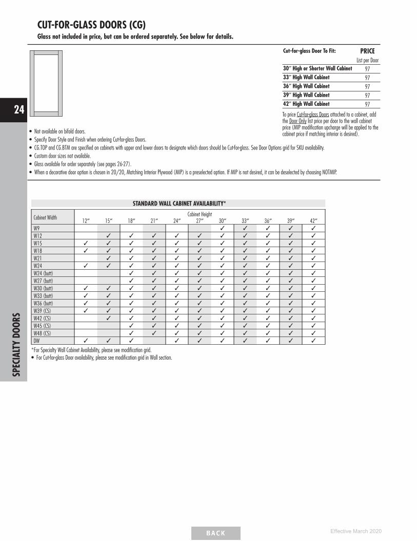
CUT-FOR-GLASS DOORS (CG)Glass not included in price, but can be ordered separately. See below for details.
• Not available on bifold doors.• Specify Door Style and Finish when ordering Cut-for-glass Doors.• CG.TOP and CG.BTM are specified on cabinets with upper and lower doors to designate which doors should be Cut-for-glass. See Door Options grid for SKU availability.• Custom door sizes not available.• Glass available for order separately (see pages 26-27).• When a decorative door option is chosen in 20/20, Matching Interior Plywood (MIP) is a preselected option. If MIP is not desired, it can be deselected by choosing NOTMIP.
Cut-for-glass Door To Fit: PRICEList per Door
30″ High or Shorter Wall Cabinet 9733″ High Wall Cabinet 9736″ High Wall Cabinet 9739″ High Wall Cabinet 9742″ High Wall Cabinet 97
To price Cut-for-glass Doors attached to a cabinet, addthe Door Only list price per door to the wall cabinetprice (MIP modification upcharge will be applied to thecabinet price if matching interior is desired).
STANDARD WALL CABINET AVAILABILITY*
Cabinet Width Cabinet Height12″ 15″ 18″ 21″ 24″ 27″ 30″ 33″ 36″ 39″ 42″
W9 ✓ ✓ ✓ ✓ ✓
W12 ✓ ✓ ✓ ✓ ✓ ✓ ✓ ✓ ✓ ✓
W15 ✓ ✓ ✓ ✓ ✓ ✓ ✓ ✓ ✓ ✓ ✓
W18 ✓ ✓ ✓ ✓ ✓ ✓ ✓ ✓ ✓ ✓ ✓
W21 ✓ ✓ ✓ ✓ ✓ ✓ ✓ ✓ ✓ ✓
W24 ✓ ✓ ✓ ✓ ✓ ✓ ✓ ✓ ✓ ✓ ✓
W24 (butt) ✓ ✓ ✓ ✓ ✓ ✓ ✓ ✓ ✓
W27 (butt) ✓ ✓ ✓ ✓ ✓ ✓ ✓ ✓ ✓
W30 (butt) ✓ ✓ ✓ ✓ ✓ ✓ ✓ ✓ ✓ ✓ ✓
W33 (butt) ✓ ✓ ✓ ✓ ✓ ✓ ✓ ✓ ✓ ✓ ✓
W36 (butt) ✓ ✓ ✓ ✓ ✓ ✓ ✓ ✓ ✓ ✓ ✓
W39 (CS) ✓ ✓ ✓ ✓ ✓ ✓ ✓ ✓ ✓ ✓ ✓
W42 (CS) ✓ ✓ ✓ ✓ ✓ ✓ ✓ ✓ ✓ ✓
W45 (CS) ✓ ✓ ✓ ✓ ✓ ✓ ✓ ✓ ✓
W48 (CS) ✓ ✓ ✓ ✓ ✓ ✓ ✓ ✓ ✓
DW ✓ ✓ ✓ ✓ ✓ ✓ ✓ ✓ ✓ ✓
*For Specialty Wall Cabinet Availability, please see modification grid.• For Cut-for-glass Door availability, please see modification grid in Wall section.
SPEC
IALT
YDO
ORS
24
Effective March 2020

MULLION DOORS (MD)Glass not included in price, but can be ordered separately. See below for details.
• Compatible glass styles are Antique, Clear, Frost, Reeded, and Seeded glass.• Specify Door Style and Finish when ordering Mullion Doors.• MD.TOP and MD.BTM are specified on cabinets with upper and lower doors to designate which doors should be Mullion Doors.
See Door Options grid for SKU availability.• Custom door sizes not available.• Shelves will not align with mullions.• When a decorative door option is chosen in 20/20, Matching Interior Plywood (MIP) is a preselected option. If MIP is not desired, it can
be deselected by choosing NOTMIP.
Mullion Door To Fit: PRICEList per Door
18″ High Wall Cabinet 39124″ High Wall Cabinet 39130″ High Wall Cabinet 39133″ High Wall Cabinet 42336″ High Wall Cabinet 42339″ High Wall Cabinet 42342″ High Wall Cabinet 423
To price Mullion Doors attached to a cabinet, addthe Door Only list price per door to the wallcabinet price (MIP modification upcharge will beapplied to the cabinet price if matching interior isdesired).
MULLION LITES GRID
Cabinet WidthCabinet Height
18″ 24″ 30″ 33″ 36″ 39″ 42″W15 G D D D A AW18 G D D D A AW21 D D D A AW24 D D D A AW24 (butt) D D D A AW27 (butt) D D D A AW30 (butt) G G D D D A AW33 (butt) D D D A AW36 (butt) G G D D D A AW42 (CS) D D D A AW45 (CS) D D D A AW48 (CS) D D D A ADW30 DDW33 DDW36 DDW39 ADW42 A
A2 x 4 Lites
D2 x 3 Lites
G2 x 2 Lites
SPEC
IALT
YDO
ORS
25
Effective March 2020

TEXTURED GLASS PANELS
Antique Bevel Clear Frost Reeded Seeded
• Cut-for-glass and mullion doors must be ordered separately. See pages 24-25.• For glass shelf kits, see page 161.• All glass is fully tempered or has a safety lamination.• When textured glass is ordered for use in wall top hinge cabinets (WTH), glass design will be turned horizontally and may not match desired pattern.• Door frame may reduce amount of glass shown.
AVAILABILITY
Cabinet WidthCabinet Height
12″ 15″ 18″ 21″ 24″ 27″ 30″ 33″ 36″ 39″ 42″W12 ✓ ✓ ✓ ✓ ✓ ✓ ✓ ✓ ✓ ✓
W15 ✓ ✓ ✓ ✓ ✓ ✓ ✓ ✓ ✓ ✓ ✓
W18 ✓ ✓ ✓ ✓ ✓ ✓ ✓ ✓ ✓ ✓ ✓
W21 ✓ ✓ ✓ ✓ ✓ ✓ ✓ ✓ ✓ ✓
W24 ✓ ✓ ✓ ✓ ✓ ✓ ✓ ✓ ✓ ✓ ✓
W24 (butt) ✓ ✓ ✓ ✓ ✓ ✓ ✓ ✓ ✓
W27 (butt) ✓ ✓ ✓ ✓ ✓ ✓ ✓ ✓ ✓
W30 (butt) ✓ ✓ ✓ ✓ ✓ ✓ ✓ ✓ ✓ ✓ ✓
W33 (butt) ✓ ✓ ✓ ✓ ✓ ✓ ✓ ✓ ✓ ✓ ✓
W36 (butt) ✓ ✓ ✓ ✓ ✓ ✓ ✓ ✓ ✓ ✓ ✓
W39 (CS) ✓ ✓ ✓ ✓ ✓ ✓ ✓ ✓ ✓ ✓ ✓
W42 (CS) ✓ ✓ ✓ ✓ ✓ ✓ ✓ ✓ ✓ ✓
W45 (CS) ✓ ✓ ✓ ✓ ✓ ✓ ✓ ✓ ✓
W48 (CS) ✓ ✓ ✓ ✓ ✓ ✓ ✓ ✓ ✓
DW ✓ ✓ ✓ ✓ ✓ ✓ ✓ ✓ ✓ ✓
TEXTURED GLASS PANELS PRICING
TEXTURED GLASS PANELS
STYLEPANEL
THICKNESS
HEIGHT
12″ – 18″ TALL 21″ – 30″ TALL 33″ – 42″ TALL
Antique 1/8″ 220 245 269Bevel 1/4″ 220 245 269Clear 1/8″ 186 206 226Frost 5/32″ 220 245 269Reeded 5/32″ 186 206 226Seeded 9/32″ 346 385 423
DECO
RATI
VEGL
ASS
INSE
RTS
26
Effective March 2020

Antique
• Glass type: Antique• Panel thickness: 1/8″
Bevel
• Glass type: Clear• Panel thickness: 1/4″• Not available with Mullion Doors.
Clear
• Glass type: Clear• Panel thickness: 1/8″
Frost
• Glass type: Frost• Panel thickness: 5/32″
Reeded
• Glass type: Reeded• Panel thickness: 5/32″
Seeded
• Glass type: Seeded• Panel thickness: 9/32″
TEXTURED GLASS PANELS
DECO
RATI
VEGL
ASS
INSE
RTS
27
Effective March 2020

CABINET DIMENSIONS
BASE CABINETWALL CABINET TWO-DRAWERBASE CABINET
with ROLL TRAY
THREE-DRAWERBASE CABINET
THREE-DRAWERBASE CABINET
with DEEP DRAWER
FOUR-DRAWERBASE CABINET
32” HIGHVANITY CABINET
32” HIGHVANITY DRAWER
BASE CABINET
34 1/2” HIGHVANITY CABINET
DESK BASE CABINET
3/4”
24”3/8”
11/2
”34
1 /2”
33/8”
14”
10”
41/2
”11
/ 2”
5”11
/2”
5”11
/2”
11/2
”
24”3/4” 3/8”11
/2”
5”
341 /
2”
33/8”
5”5”
41/2
”71
/2”
11/2
”11
/2”
11/2
”
63/8
”
11/2
”
21”
3/4” 3/8”11/2
”
32”
33/8”
41/2
”18
”11
/2”
5”
11/2
”
21”
3/4” 3/8”11/2
”41
/2”
341 /
2 ”
33/8”
201 /
2”11
/2”
5”
11/2
”
21”
3/4” 3/8”11/2
”
29”
33/8”
41/2
”15
”11
/2”
5”
3/4”24”
3/8”
11/2
”34
1 /2”
33/8”
87/8
”63
/8 ”85
/8”
63/8 ”
3”41
/2”
11/2
”5”
11/2
”
3/4”24”
11/2”
12”
30”
3”
41/2”
33/8”
63 /8
”
12”
63 /8
”
3/8”
11/2”
33/8”
11/2
”11
/2”
24”3/4” 3/8”11
/2”
41/2
5””
341 /
2”
201 /
2”
15”
33/8”
12”
11/2
”
3/4” 3/8”
11/2
”
3/4”
21”
3/8”
33/8”
11/2
”32
”
71/2
”71
/2”
5”
63/8
”63
/8”
33/8”
41/2
”11
/2”
11/2
”3”
CABI
NET
DIM
ENSI
ONS
28
Effective March 2020

CABINET DIMENSIONS
UTILITY CABINET TALL BUILT-INMICROWAVE CABINET
OVEN MICROWAVECOMBO CABINET
SINGLE OVEN CABINET
DOUBLE OVEN CABINET LC/LCRH CABINET VANITY UTILITYCABINET
11/2
”
12 or 24”3/4” 3/8”11
/2”
84”
33/8”
3”58
1 /2”
41/2
”15
”
11/2
”11
/2”
24”3/4” 3/8”11
/2”
84”
33/8”
6”13
1 /2”
41/2
”20
1 /2”
24”
6”5”
21”
84”
241 /
2”31
/2”
241 /
2”11
/2” 3/4” 3/8”
33/8”
11/2
”41
/2”
191/2”
31/2
”20
1 /2”
11/2
”11
/2”
24”3/4” 3/8”11
/2”
84”
33/8”
6”22
1 /2”
41/2
”20
1 /2”
15”
6”5”
11/ 2
”
24”3/4” 3/8”11
/2”
84”
33/8”
9”28
1 /2”
41/2
”15
”9”
15”
11/2
”
24”3/4” 3/8”11
/2”
84”
33/8”
9”39
”41
/2”
15”
4”9
1 /2”
21”
84”
27”
3”46
1 /2 ”
11/2
” 3/4” 3/8”
33/8”
11/2
”41
/2”
5” 15”
CABI
NET
DIM
ENSI
ONS
29
Effective March 2020

CABINET DIMENSIONSROLL TRAY POSITIONS
1RT 2RT 3RT 4RT
FRONT VIEW FRONT VIEW FRONT VIEW FRONT VIEW
231/16”
1231/32” 1231/32”
623/32”
121/32”
121/32”
121/32”
121/32”
121/32”
715/16”
1RT 2RT 3RT 4RT
FRONT VIEW FRONT VIEW FRONT VIEW FRONT VIEW
67/32” 615/32”
121/32”
169/16”
623/32” 121/32”
121/32”
121/32”
121/32”
17/16”
1RT 2RT 3RT 4RT 5RT
FRONT VIEW FRONT VIEW FRONT VIEW FRONT VIEW FRONT VIEW
549/16”
267/8”
113/4”
113/4”
113/4”
113/4”
113/4”
113/4”
623/32”
91/4”
1123/32”
245/16” 245/16”
45/32”
623/32”
1RT 2RT
FRONT VIEWFRONT VIEW
209/16”
101/16”
71/8”
BASE CABINETS AND 34 1/2” HIGH VANITY CABINETS
FULL HEIGHT BASE CABINETS
UTILITY CABINETS
1RT
FRONT VIEW
2RT
FRONT VIEW
111/16”63/16”
11/2”
DESK DOOR DRAWER BASE CABINETS32” HIGH VANITY CABINETS
CABI
NET
DIM
ENSI
ONS
30
Effective March 2020

CABINET DIMENSIONS
84″ HIGH APPLICATIONNumber after Wall Cabinet Represents Height of Cabinet
11/2”
11/2”
11/2” 11/2”
9”12” 15”
18”
W12 W15 W18 W21 W30 84” U
21” 24”27”
15”
18”
11/2”
18”
WO
3DB 4DB
11/2” ThickCountertop
11/2”
11/2”30”
TOEKICK AREA
11/2”
201/2”
41/2”
5” 5”
87/8”
85/8”
3”
5”
5”
5”
71/2”
11/2”
11/2”
581/2”
39”
41/2”
9”PANEL
OPENING
9”PANEL3”
15”
84” OCD
TOEKICK AREA TOEKICK AREATOEKICK AREATOEKICK AREA
41/2”
41/2”
W3D48
27”
27/8”
W24 W27
21/8”
2”
2”
11/2”
12”
12”
3”
TOEKICK AREA
B
6”WAGD
161/2”
2DBRT2DB
3DBDD
TOEKICK AREA
5”
5”
14”
11/2”
3” 3”
PANEL
PANEL 9”
41/2”OPENING
9”
18”
18”
3”
15”
84” OMC
TOEKICK AREA
3” 3”
87″ HIGH APPLICATIONNumber after Wall Cabinet Represents Height of Cabinet
6”
11/2”
11/2”
11/2” 11/2”
9”12” 15”
18”
W12 W15 W18 W21 W30 87” U
21” 24”27”
18”
18”
11/2”
WAGD
161/2” 18”
WO
3DB 4DB
11/2” ThickCountertop
TOEKICK AREA
201/2”
5” 5”
87/8”
85/8”
3”
5”
71/2”
11/2”
11/2”
581/2”
39”
41/2”
9”PANEL
OPENING
PANEL
PANEL 9”
41/2”OPENING
9”
18”
18”
9”PANEL3”
87” OCD 87” OMCW33
30”
18”
3”
18”
TOEKICK AREATOEKICK AREATOEKICK AREA
5”
5”
TOEKICK AREA TOEKICK AREA
41/2”
41/2”
W3D51
30”
27/8”21/8”
2”
2”
11/2”
12”
12”
2DBRT
3”
TOEKICK AREA
B11/2”
11/2”30”
11/2”
41/2”
3DBDD
TOEKICK AREA
5”
5”
14”
11/2”
3” 3” 3”3”
W24 W27
2DB
• 1 1/2″ Top and Bottom Rails - Wall and Base Cabinets.• 1 1/2″ Vertical Stiles.• 3″ Center Vertical Rails on Wall and Base Cabinets
to Divide Double Door Cabinets on 39″ Wide and Over.
Full Overlay Door Styles:• 1/4″ Reveal Around Doors (1/4″ of Face Frame Shows).• Frame Opening + 2 1/2″ = Door Size for
Base/Wall Cabinets.• 4 1/2″ or 5″ High Drawer Opening = 6 1/4″ Drawer Front.• 7 1/2″ High Drawer Opening = 10″ Drawer Front.• 8 5/8″ and 8 7/8″ Drawer Opening = 11 3/8″
Drawer Front.• 12″ High Drawer Opening = 14 1/2″ Drawer Front.• 14″ High Drawer Opening = 16 1/2″ Drawer Front.
1/2″ Overlay Door Styles:• 1″ Reveal Around Doors (1″ of Face Frame Shows).• Frame Opening + 1″ = Door Size for
Base/Wall Cabinets.• 4 1/2″ or 5″ High Drawer Opening = 5 1/2″
Drawer Front.• 7 1/2″ High Drawer Opening = 8 1/2″
Drawer Front.• 8 5/8″ Drawer Opening = 9 7/8″ Drawer Front.• 8 7/8″ Drawer Opening = 10 5/8″ Drawer Front.• 12″ High Drawer Opening = 13″ Drawer Front.• 14″ High Drawer Opening = 15″ Drawer Front.
CABI
NET
DIM
ENSI
ONS
31
Effective March 2020

CABINET DIMENSIONS90″ HIGH APPLICATION
Number after Wall Cabinet Represents Height of Cabinet
6”
11/2”
11/2”
11/2” 11/2”
9”12” 15”
18”
W12 W15 W18 W21 W30 W33 90” U
21” 24”27”
21”
18”
11/2”
WAGD
161/2” 18”
WO
3DB 4DB
11/2” ThickCountertop
TOEKICK AREA
201/2”
5” 5”
87/8”
85/8”
3”
5”
71/2”
11/2”
11/2”
581/2”
39”
41/2”
9”PANEL
OPENING
9”PANEL3”
90” OCDW36
33”
21”
TOEKICK AREATOEKICK AREA
5”
5”
TOEKICK AREA TOEKICK AREA
41/2”
41/2”
W3D54
33”
27/8”21/8”
2”
2”
11/2”
12”
12”
2DBRT2DB
3”
TOEKICK AREA
B
11/2”30”
11/2”
41/2”
3DBDD
TOEKICK AREA
5”
5”
14”
11/2”
3” 3”
PANEL
PANEL 9”
41/2”OPENING
9”
18”
18”
90” OMC
3”
21”
TOEKICK AREA
3”3”
W24 W27
30”
93″ HIGH APPLICATIONNumber after Wall Cabinet Represents Height of Cabinet
93” U
24”
18”
11/2”
WAGD
161/2”
3DB 4DB
11/2” ThickCountertop
11/2”
11/2”30”
TOEKICK AREA
11/2”
201/2”
41/2”
5” 5”
87/8”
85/8”
3”
5”
71/2”
11/2”
11/2”
581/2”39”
41/2”
9”PANEL
OPENING
PANEL
PANEL 9”
41/2”OPENING
9”
18”
18”
9”PANEL3”
93” OCD 93” OMC
3”
PEDESTALPEDESTALPEDESTAL
5”
5”
TOEKICK AREA TOEKICK AREA
W39
36”
18”
24” 24”
41/2”
41/2”
W3D57
36”
27/8”21/8”
2”
2”
11/2”
12”
12”
2DBRT2DB
3”
TOEKICK AREA
B
11/2”9”
12” 15”18”
W12 W15 W18 W21 W30
21” 24” 27”
W36
33”
6”
WO
11/2”
11/2” 11/2”
5”
5”
TOEKICK AREA
14”
3DBDD
11/2”
3” 3” 3” 3”
W24 W27
30”
W33
• 1 1/2″ Top and Bottom Rails - Wall and Base Cabinets.• 1 1/2″ Vertical Stiles.• 3″ Center Vertical Rails on Wall and Base Cabinets
to Divide Double Door Cabinets on 39″ Wide and Over.
Full Overlay Door Styles:• 1/4″ Reveal Around Doors (1/4″ of Face Frame Shows).• Frame Opening + 2 1/2″ = Door Size for
Base/Wall Cabinets.• 4 1/2″ or 5″ High Drawer Opening = 6 1/4″ Drawer Front.• 7 1/2″ High Drawer Opening = 10″ Drawer Front.• 8 5/8″ and 8 7/8″ Drawer Opening = 11 3/8″
Drawer Front.• 12″ High Drawer Opening = 14 1/2″ Drawer Front.• 14″ High Drawer Opening = 16 1/2″ Drawer Front.
1/2″ Overlay Door Styles:• 1″ Reveal Around Doors (1″ of Face Frame Shows).• Frame Opening + 1″ = Door Size for
Base/Wall Cabinets.• 4 1/2″ or 5″ High Drawer Opening = 5 1/2″
Drawer Front.• 7 1/2″ High Drawer Opening = 8 1/2″
Drawer Front.• 8 5/8″ Drawer Opening = 9 7/8″ Drawer Front.• 8 7/8″ Drawer Opening = 10 5/8″ Drawer Front.• 12″ High Drawer Opening = 13″ Drawer Front.• 14″ High Drawer Opening = 15″ Drawer Front.
CABI
NET
DIM
ENSI
ONS
32
Effective March 2020
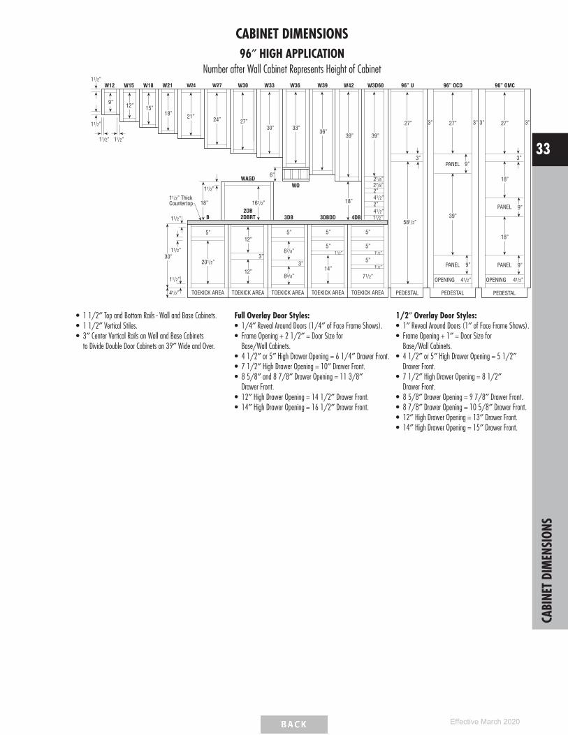
CABINET DIMENSIONS96″ HIGH APPLICATION
Number after Wall Cabinet Represents Height of Cabinet11/2”
9”12” 15”
18”
W12 W15 W18 W21 W30 W33 96” U
21” 24”27”
18”
11/2”
WAGD
161/2”
6”
WO
3DB 4DB
11/2” ThickCountertop
11/2”
11/2”30”
TOEKICK AREA
11/2”
201/2”
41/2”
5” 5”
87/8”
85/8”
3”
5”
71/2”
11/2”
11/2”
581/2”39”
41/2”
9”PANEL
OPENING
9” PANEL3”
96” OCDW36
33”
PEDESTALPEDESTAL
5”
5”
TOEKICK AREA TOEKICK AREA
W42
39”
18”
27”
41/2”
41/2”
W3D60
39”
27/8”21/8”
2”
2”
11/2”
12”
12”
2DBRT2DB
3”
TOEKICK AREA
B
11/2”
11/2” 11/2”
5”
5”
TOEKICK AREA
14”
3DBDD
11/2”
3” 3”
W39
36”
PANEL
PANEL 9”
41/2”OPENING
9”
18”
18”
96” OMC
3”
PEDESTAL
27” 3”3”
W24 W27
30”27”
• 1 1/2″ Top and Bottom Rails - Wall and Base Cabinets.• 1 1/2″ Vertical Stiles.• 3″ Center Vertical Rails on Wall and Base Cabinets
to Divide Double Door Cabinets on 39″ Wide and Over.
Full Overlay Door Styles:• 1/4″ Reveal Around Doors (1/4″ of Face Frame Shows).• Frame Opening + 2 1/2″ = Door Size for
Base/Wall Cabinets.• 4 1/2″ or 5″ High Drawer Opening = 6 1/4″ Drawer Front.• 7 1/2″ High Drawer Opening = 10″ Drawer Front.• 8 5/8″ and 8 7/8″ Drawer Opening = 11 3/8″
Drawer Front.• 12″ High Drawer Opening = 14 1/2″ Drawer Front.• 14″ High Drawer Opening = 16 1/2″ Drawer Front.
1/2″ Overlay Door Styles:• 1″ Reveal Around Doors (1″ of Face Frame Shows).• Frame Opening + 1″ = Door Size for
Base/Wall Cabinets.• 4 1/2″ or 5″ High Drawer Opening = 5 1/2″
Drawer Front.• 7 1/2″ High Drawer Opening = 8 1/2″
Drawer Front.• 8 5/8″ Drawer Opening = 9 7/8″ Drawer Front.• 8 7/8″ Drawer Opening = 10 5/8″ Drawer Front.• 12″ High Drawer Opening = 13″ Drawer Front.• 14″ High Drawer Opening = 15″ Drawer Front.
CABI
NET
DIM
ENSI
ONS
33
Effective March 2020
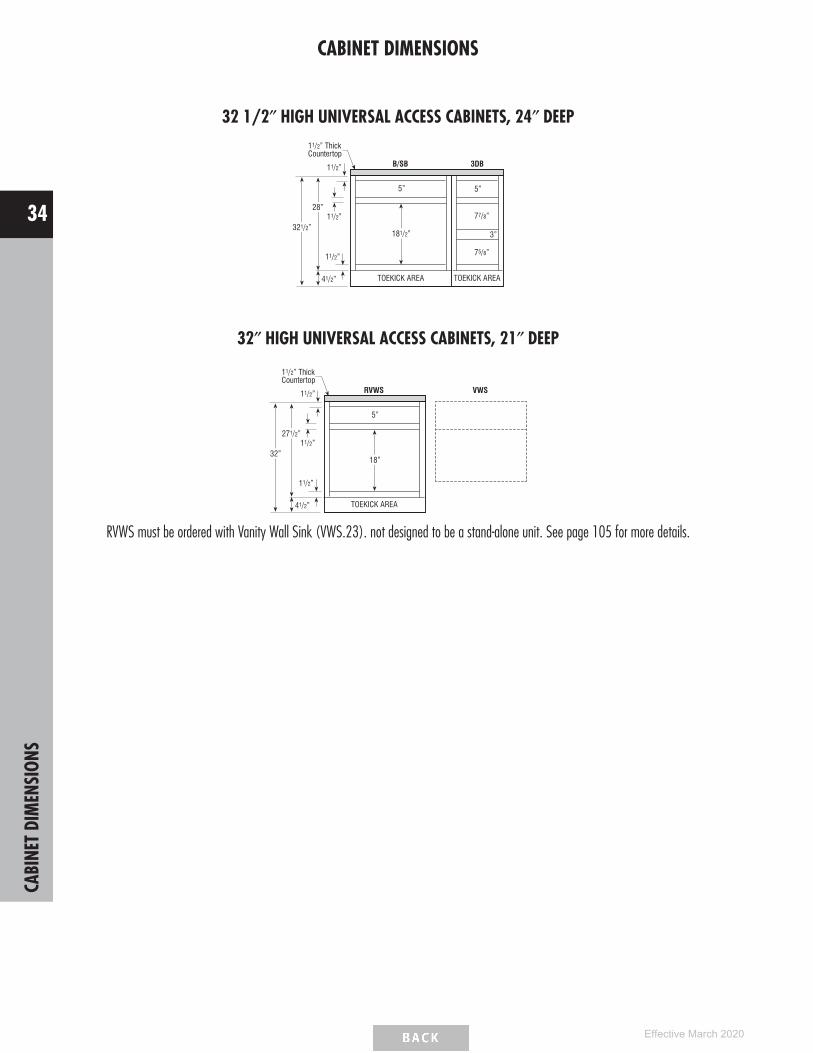
CABINET DIMENSIONS
32 1/2″ HIGH UNIVERSAL ACCESS CABINETS, 24″ DEEP
B/SB11/2”
11/2”28”
TOEKICK AREA
11/2”
181/2”
41/2”
5”
77/8”
3”321/2”
75/8”
5”
3DB
TOEKICK AREA
11/2” ThickCountertop
32″ HIGH UNIVERSAL ACCESS CABINETS, 21″ DEEP
RVWS VWS11/2”
11/2”271/2”
11/2”
18”
41/2”
5”
32”
TOEKICK AREA
11/2” ThickCountertop
RVWS must be ordered with Vanity Wall Sink (VWS.23). not designed to be a stand-alone unit. See page 105 for more details.
CABI
NET
DIM
ENSI
ONS
34
Effective March 2020
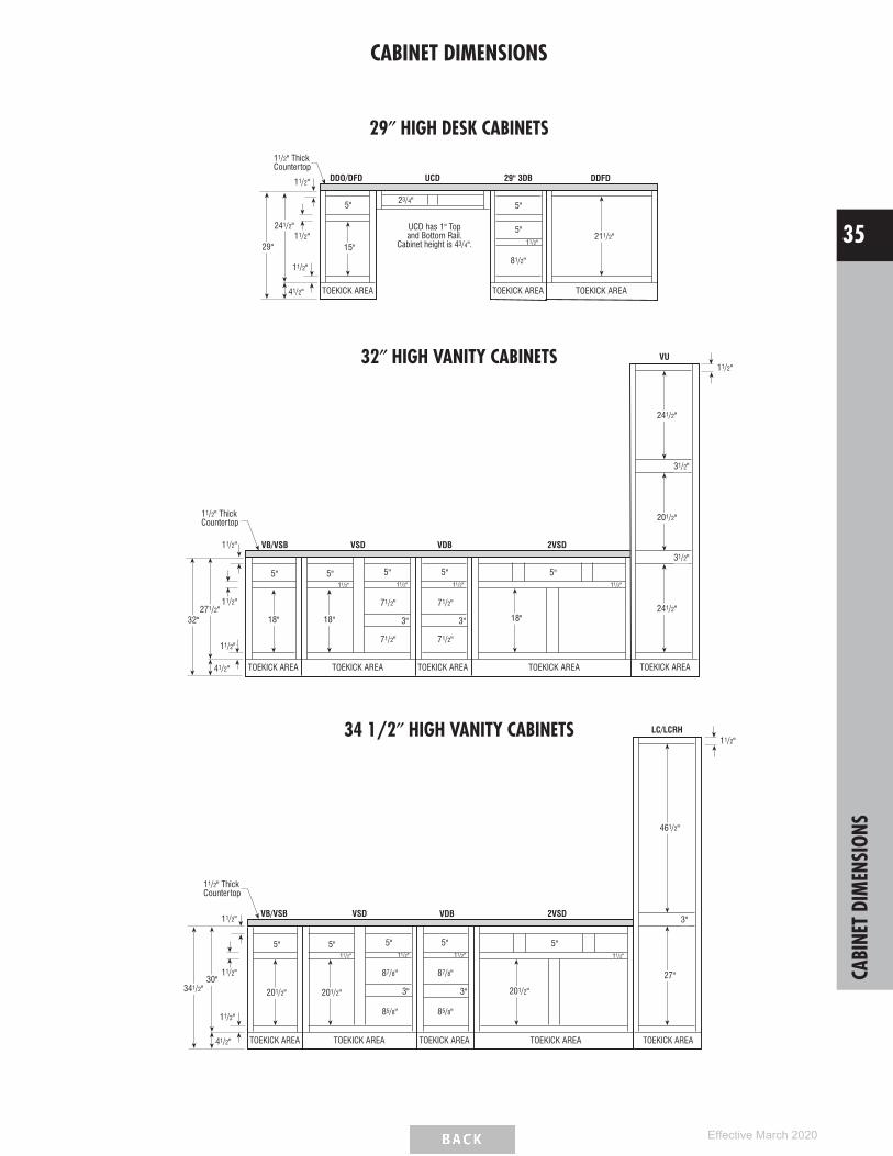
CABINET DIMENSIONS
29″ HIGH DESK CABINETS
TOEKICK AREA
DDO/DFD11/2"
11/2"241/2"
TOEKICK AREA
11/2"
15"
41/2"
5"
5"
29"
UCD
81/2"
5"23/4"
UCD has 1" Topand Bottom Rail.
Cabinet height is 43/4".
29" 3DB
TOEKICK AREA
211/2"
DDFD
11/2" ThickCountertop
11/2"
32″ HIGH VANITY CABINETS
VB/VSB
271/2"
TOEKICK AREA
18"
41/2"
5" 5"
3"
11/2"
32"
VSD
71/2"
5"
3"
11/2"
71/2"
71/2" 1/2"
2VSD
18"
5"11/2"
TOEKICK AREA TOEKICK AREATOEKICK AREA
241/2"
31/2"
201/2"
31/2"
241/2"
11/2"VU
TOEKICK AREA
VDB
11/2" ThickCountertop
11/2"
11/2"
11/2"
18"
5"11/2"
7
34 1/2″ HIGH VANITY CABINETS
VB/VSB11/2"
11/2"30"
TOEKICK AREA
11/2"
201/2"
41/2"
5" 5"
3"
11/2"
341/2"
VSD
87/8"
5"
3"
85/8"
2VSD
201/2"
5"11/2"
TOEKICK AREA TOEKICK AREATOEKICK AREA
87/8"
85/8"
VDB
11/2" ThickCountertop
11/2"
27"
3"
461/2"
11/2"LC/LCRH
TOEKICK AREA
201/2"
5"11/2"
CABI
NET
DIM
ENSI
ONS
35
Effective March 2020

CABINET DIMENSIONS
DIMENSIONS FOR CORNER INSTALLATIONS (45° DIAGONAL)
12″ DEEP CABINETS
For dimensions more than noted, add 2 1/8″ to walldimensions for every 3″ increment of cabinet front.Example: 39″ cabinet front would be 37 1/2″ +2 1/8″ = 39 5/8″.
24″ DEEP CABINETS
For dimensions more than noted, add 2 1/8″ to walldimensions for every 3″ increment of cabinet front.Example: 39″ cabinet front would be 49 1/2″ +2 1/8″ = 51 5/8″.
INSTALLATION HEIGHT REQUIREMENTS
MinimumInstallation
Heightfor
CabinetDepth
LiftDirection
Height of ceiling needs to be considered for installation of tall cabinets. Cabinet height below includes toekick area:
Cabinet HeightMinimum Installation Height for Cabinet Depth
12″ 15″ 18″ 21″ 24″84″ 84 7/8″ 85 11/32″ 85 15/16″ 86 19/32″ 87 3/8″87″ 87 27/32″ 88 5/16″ 88 27/32″ 89 1/2″ 90 1/4″90″ 90 13/16″ 91 1/4″ 91 13/16″ 92 7/16″ 93 5/32″
93″ * 89 5/16″ 89 25/32″ 90 5/16″ 90 31/32″ 91 23/32″96″ * 92 5/16″ 92 3/4″ 93 9/32″ 93 29/32″ 94 5/8″
*Separate pedestal base included with cabinet to be installed after cabinet is in an upright position.
CABI
NET
DIM
ENSI
ONS
36
Effective March 2020

POLICIES
CABINET INSTALLATION INSTRUCTIONShttps://www.masterbrand.com/installation
DISCONTINUED PRODUCT POLICY60 days minimum notice to reps and customers announcing the discontinuation of a product line.
Product will no longer be available for order after the discontinuation date. Only warranty orders will be considered. Even with warranty orders we will have the option to replace customer’s defectiveproduct with the same discontinued product they originally purchased, or replace all doors originally ordered with a current product that is similar in appearance.
EXPRESS RESPONSE™ POLICYSchrock’s Express Response program is designed to expedite orders when customers need product faster than normal lead times to correct problems with an existing order. Below is an overview ofthe program and what you can expect from Schrock’s commitment to superior service.
GUIDELINES• Order must be associated with a previous order number.• All orders received by 12 NOON E.T. Monday-Friday will be automatically scheduled for Express Response that same day. Orders received after the cutoff time will be processed on the next
business day.• Lead time calculation is based on receipt of a clean order on a credit-worthy account. Clean orders are orders in which all information is provided and accurate.• There is no additional up-charge for Express Response.• There are no cancellations or returns once order is received.• Due to the special nature of Special Orders and Appliance Panels, they are excluded from the Express Response program and will be processed as a standard lead time order.• Express Response is available within the continental United States. Should Alaska, Hawaii or international shipments be required, customer service representatives are ready to assist by
providing shipping information and determining lead times.
LEAD TIMES12 WORKING DAYS OR LESS FROM ORDER TO DELIVERY (channel partner or home delivery agent):
• Items shipped via LTL (via SuperPAC™) or truckload.• Includes all catalog items except those that can be expedited through the 5-day program listed below.
5 WORKING DAYS FROM ORDER TO DELIVERY• Qualified items are designated in the Pricing/Specification Guide with an icon• Items will ship via parcel ground.
° Lead time calculation allows for 2 days parcel ground shipping time. Some geographic areas may require additional shipping time.• For orders containing both 12 day and 5 day items, the longer lead time applies.
POLI
CIES
37
Effective March 2020

SCHROCK CABINETRY’S DESIGN CHECKLISTCONSTRUCTION OPTIONSConsider exposed end options:
Modify exposed cabinet ends to FPEB.Apply 1/4″ skin to hide 1/4″ reveal. This will allow the ends to age uniformlywith the rest of the kitchen and will make it flush.Apply decorative door kit (BEDSD, WED, TED). This kit includes 1/4″ skin,decorative doors, and screws for field installation.
WOOD AND FINISH CHARACTERISTICSReview specific details with the customer:
Mineral Streaks, Birdseye Dots, Grain Variations.Color Variations/Darkening.Finish Variations, hairline cracks may develop at frame joints on painted frame.Underside of cabinets are natural maple laminate. Use light rail or cabinet paneledge and skin to hide, especially when designing with peninsula wall cabinets.
SMART SOLUTIONS™
Review storage and usage needs with Customer. See page 41 for complete chart.Cooking Solutions:• Wall Spice Rack CabinetStorage Solutions:• SuperCabinet™• Pegged Dish Organizer• Wall Message CenterClean-up Center:• Base Wastebasket
CLEARANCESAdd fillers between end cabinets and walls on full overlay door styles.Allow space between door/window trim and end cabinets for countertop and topmoulding overhang.Include refrigerator door hinges in overall refrigerator height when placing cabinetsabove it.
Maintain a minimum clearance of 3″ by pulling blind corners as follows:Full Overlay: 1 1/4″, Standard Overlay 1/2″. (More is needed in certainsituations such as when adjacent to an appliance or when using oversized pulls orknobs.)Allow sufficient clearance (3″) on each side of accessory cabinets (such asroll-out trays, etc). Doors on these cabinets must open fully for accessories to befunctional.Ensure the height between the cooktop and range hood is 24″ to meet NKBAguidelines.
Qualify customer carefully on upper cabinet/microwave advantages/disadvantages asfollows:
Minimum of 18″ from cooktop to upper cabinet/above the range microwavewhich allows for easy access to either, but less room over back burner.Minimum of 21″ from cooktop to upper cabinet/microwave which allows foraccess to large pots on back burner of cooktop, but longer reach to microwave.
FILLERSPlace fillers toward end of run where least conspicuous if needed.Attach overlay fillers on top of the base, wall, or tall fillers when using full overlaydoor styles to maintain a consistent reveal. Don’t forget to include blind cornerfillers.Add a filler at least 6″ wide to accommodate a decorative onlay when the filler isused as valance.
VARYING HEIGHTS AND DEPTHSAlso increase the depth of a wall cabinet run when you increase the height (somoulding on adjacent cabinet will kill into the side of the taller cabinet).Skin the sides of tall cabinets to 1) hide the seam between the toekick pedestal andthe cabinet, 2) keep adjacent base and wall cabinets out from reveal of tall cabinet.Add increased depth on tall end panels for a built-in look for deep refrigerators.Account for the additional support needed for wall cabinets with a depth of 18″ orgreater. This can be achieved by installing a soffit or end panels.
MATCHING INTERIOR CABINETS/GLASS OPTIONSVerify cut-for-glass or mullion door option is available on desired cabinet size.(See pages 24-25 for available cut-for-glass/mullion door sizes.)Verify glass insert option is available for desired cut-for-glass door size chosen.Verify matching interior option has been selected for all open or glass cabinets.Use light rail and skin to hide color variation between bottom of cabinets with andwithout matching interior.Verify mullion door lite grid matches customer expectations.
MOULDINGSVerify correct amount of crown moulding has been ordered.Order toekick caps.Order extra scribe.
ISLANDS AND PENINSULASConsider standard height bars are 34 1/2″ tall and require 19″ knee space. Raisedbars are 42″ tall.Consider base peninsula cabinets (P) are 24 1/4″ deep and require 12″ of kneespace. Use back panels/doors to flush non-P cabinets with P cabinets.Use outside corner moulding if a skin is exposed on the back of the island.
APPLIANCESNote for all consumers, appliances are not included with any cabinetry product.
Do not place dishwashers next to diagonal front cabinet (interference) or next to arange (no countertop support).Verify refrigerator door has enough clearance to open beyond 90 degrees sorefrigerator drawers can be utilized. Refer to appliance manufacturer’s specs.Add TF696FH, as it may be required to frame around built-in microwave ovens andother built-in items. Refer to appliance manufacturer’s specs.Order appliance panels.
SPECIAL CONSIDERATIONSConsider V-groove skins and/or decorative doors on exposed cabinet sides.
MISCELLANEOUSOrder full size touch-up kit (mini touch-up kit included with standard sink base).
DESI
GNCH
ECKL
IST
38
Effective March 2020

NKBA GUIDELINESkitchen planning guidelinesDOOR/ENTRY• Door opening should be at least 32″ wide, requiring a minimum 2′ 10″ wide door.
DOOR INTERFERENCE• Entry door should not interfere with safe appliance operation or appliance doors.
DISTANCE BETWEEN WORK CENTERS• With three work centers, the total distance traveled should not be more than 26′
with no single leg of the triangle less than 4′ or more than 9′.• With more than three work centers, each additional travel distance to another work
center should be no less than 4′ or more than 9′. Each leg is measured from thecenter-front of the appliance/sink. No work triangle leg should intersect anisland/peninsula by more than 12″.
SEPARATING WORK CENTERS• A tall obstacle should not separate two primary work centers. A properly recessed tall
corner unit is acceptable.
WORK TRIANGLE TRAFFIC• Major traffic patterns should not cross through the basic work triangle.
WORK AISLE• The work aisle should be at least 42″ for one cook and at least 48″ for multiple
cooks.
WALKWAY• The walkway width should be at least 36″.
TRAFFIC CLEARANCE AT SEATING• Allow 32″ of clearance from the table to wall/obstacle if no traffic passes behind a
seated diner. If traffic passes behind the diner, allow at least 36″ to edge past or44″ to walk past.
SEATING CLEARANCE• 30″ high tables/counters should allow a 24″ wide by 18″ deep space for each
seated diner and at least 18″ knee space.• 36″ high counters should allow a 24″ wide by 15″ deep space for each seated
diner and at least 15″ kneespace.• 42″ high counters should allow a 24″ wide by 12″ deep space for each seated
diner and at least 12″ kneespace.
CLEAN-UP/PREP SINK PLACEMENT• With only one sink, locate it adjacent to or across from the cooking surface and
refrigerator.
CLEAN-UP/PREP SINK LANDING AREA• Include at least a 24″ wide landing space on one side of the sink and 18″ on the
other.• If all the countertop at the sink is not the same height, plan a 24″ landing space on
one side of the sink and 3″ of countertop frontage on the other, both at the sameheight of the sink.
PREPARATION/WORK AREA• Include a section of countertop at least 36″ wide x 24″ deep next to the sink for a
work area.
DISHWASHER PLACEMENT• Nearest edge of dishwasher should be within 36″ of nearest edge of sink. Provide at
least 21″ of standing space between the edge of the dishwasher and countertopfrontage/appliances/cabinets which are placed at a right angle to the dishwasher.
WASTE RECEPTACLES• Include at least 2 waste receptacles, one near the sink and the other nearby for
recycling.
AUXILIARY SINK• Provide at least 3″ of countertop frontage on one side of the auxiliary sink and 18″
on the other side, both at the same height as the sink.
REFRIGERATOR LANDING AREA• Include at least 15″ of landing area on the handle side of the refrigerator, 15″ on
either side of a side-by-side refrigerator, 15″ of landing space which is no more than48″ across from the front of the refrigerator, and 15″ above or adjacent to any under-counter style refrigerator.
COOKING SURFACE LANDING AREA• Include a minimum of 12″ of landing area on one side of the cooking surface and
15″ on the other.• If cooking surface is at a different countertop height than the rest of the kitchen, then
the 12″ and 15″ landing areas must be the same height as the cooking surface.• For safety reasons, in an island or peninsula situation, the countertop should extend a
minimum of 9″ behind the cooking surface if the counter height is the same height asthe cooking surface.
COOKING SURFACE CLEARANCE• Allow 24″ between the cooking surface and a protected noncombustible surface
above it.• At least 30″ of clearance is required between the cooking surface and an
unprotected/combustible surface above it.• If a microwave/hood combination is used, then the manufacturer’s specifications
should be followed.
COOKING SURFACE VENTILATION• A correctly sized, ducted ventilation system is recommended for all cooking surface
appliances. The recommended minimum is 150 CFM.• Code requires that the manufacturer’s specifications be followed. Minimum exhaust
rate for a ducted hood is 100 CFM and must be ducted to the outside.• Make-up air may need to be provided. Refer to local codes.
COOKING SURFACE SAFETY• Do not locate cooking surface under an operable window.• Window treatments above cooking surface should not use flammable materials.• Place a fire extinguisher near the kitchen exit away from cooking equipment.
MICROWAVE OVEN PLACEMENT• The ideal location for the bottom of the microwave is 3″ below the principle user’s
shoulder, but no more than 54″ above the floor.
MICROWAVE LANDING AREA• Provide at least 15″ above, below, or adjacent to the handle side of a microwave
oven.
OVEN LANDING AREA• Include at least 15″ next to or above the oven.• A 15″ landing area that is not more than 48″ away is also acceptable as long as the
oven does not open into a walkway.
COMBINING LANDING AREAS• If two landing areas are adjacent to one another, determine a new minimum for the
two by taking the longer of the two and adding 12″.continued NK
BAGU
IDEL
INES
39
Effective March 2020

NKBA GUIDELINES
kitchen planning guidelines (continued) bathroom planning guidelines
COUNTERTOP SPACE• A total of 158″ of countertop frontage, 24″ deep, with at least 15″ clearance above
is needed to accommodate all landing, preparation, work, and storage areas.
COUNTERTOP EDGES• Clipped or round corners, rather than sharp edges, are recommended on all counters.
STORAGE• The recommended total shelf/drawer frontage for a small kitchen (less than 150
square feet) is 1400″, for a medium kitchen (151 to 350 square feet) is 1700″,and for a large kitchen (greater than 350 square feet) is 2000″.
Sizes: S M LWall 300″ 360″ 360″Base 520″ 615″ 660″Drawer 360″ 400″ 525″Pantry 180″ 230″ 310″Misc. 40″ 95″ 145″
• The totals for wall, base, drawer, and pantry shelf/drawer frontage can be adjustedupward or downward as long as the recommended total stays the same.
STORAGE AT CLEAN-UP/PREP SINK• The recommended total for a small kitchen is 400″, a medium kitchen is 480″, a
large kitchen is 560″, and should be located within 72″ of the centerline of themain clean-up/prep sink.
CORNER CABINET STORAGE• At least one corner cabinet should include a functional storage device.
ELECTRICAL RECEPTACLES• GFCI (Ground-Fault-Circuit-Interrupter) protection is required on all receptacles
servicing countertop surfaces within the kitchen.
LIGHTING• Every work surface should be well illuminated. At least one wall switch-controlled
light must be placed at the entrance.• Window/skylight area, equal to at least 8% of the total square footage of the
kitchen, or a total living space which includes a kitchen, is required.
DOOR/ENTRY• Doorway opening should be at least 32″, requiring a minimum 2′ 10″ wide door.
DOOR INTERFERENCE• The door area should include clear floor space for maneuvering which varies according
to the type of door and the direction of the approach.
CEILING HEIGHT• Bathroom floor to ceiling minimum height is 80″. A shower or tub with a shower head
shall have a minimum floor to ceiling height of 80″ above a minimum area 30″ x30″ at the shower head.
CLEAR SPACE• Plan a clear space of 30″ from the front edge of all fixtures to any opposite bath
fixture, wall, or obstacle.• A minimum space of at least 21″ is required in front of a lavatory, toilet, bidet, and
tub, with a 24″ minimum space in front of a shower entry.
SINGLE LAVATORY PLACEMENT• The distance from the centerline of the lavatory to the sidewall/tall obstacle should be
at least 20″.• The minimum distance required is 15″. The minimum distance required between a
wall and the edge of a lavatory is 4″.
DOUBLE LAVATORY PLACEMENT• The distance between the centerlines of two lavatories should be at least 36″.• The minimum distance required is 30″.• The minimum distance required between the edges of two lavatories is 4″.
LAVATORY/VANITY HEIGHT• The height for a lavatory varies from 32″ to 43″ to fit the user.
COUNTERTOP EDGES• Clipped or round corners, rather than sharp edges, are recommended on all counters.
SHOWER SIZE• The interior shower size should be at least 36″ x 36″. The minimum interior shower
size required is 30″ x 30″.
STORAGE• Provide adequate, accessible storage for toiletries, bath linens, grooming and general
bathroom supplies.• Storage of frequently used items should be 15″ to 48″ above floor.
ELECTRICAL RECEPTACLES• All GFCI receptacles should be located at electrical appliance points of use.
Load bearing floors and shelves meet KCMA standards of 15 lbs. persquare foot. Warranty does not cover overloading beyond this point.
To view a complete and updated list of the NKBA Guidelines, visithttps://nkba.org/info/guidelines
© Copyright 2007 National Kitchen & Bath Association
NKBA
GUID
ELIN
ES
40
Effective March 2020

SMART SOLUTIONS™ REFERENCE CHARTWall Cabinets Description 3″ 6″ 9″ 12″ 15″ 18″ 21″ 24″ 27″ 30″ 33″ 36″ 39″ 42″ 45″ 48″ Page
WBCPO_ _ _OL Wall Box Column Pull-outs (Overlay) • • 72
WMC12_ _ L or R Wall Message Center • 75
WSC1818_ _ Wine Storage Cabinet • 74
WSP_ _ _ _ Wall Spice Pull-outs • • 73
Base Cabinets
2DB_ _RT Two Drawer Bases w/Roll Tray • • • 95
3DB_ _WTCD Three Drawer Bases w/Wood Tiered Cutlery Divider Drawer • • • • 96
3DBDD_ _ Three Drawer Bases w/Deep Drawer • • 96
4DB_ _WTCD Four Drawer Bases w/Wood Tiered Cutlery Divider Drawer • • • • 97
B_ _RTWTCD L or R, B24RTWTCD Bases w/Wood Tiered Cutlery Divider Drawer and Roll Tray • • • • 83
B_ _TDRO L or R Bases w/Roll-out Tray Divider • • 84
B_ _WTCD L or R, B24WTCD Bases w/Wood Tiered Cutlery Divider Drawer • • • • 81
BBCPO_OL Base Box Column Pull-outs (Overlay) • • 99
BPP_ _ Base Pantry Pull-outs • • 98
BPPP24 Base Pots & Pans Pull-out • 84
BSC_ _ _ _ _ SuperCabinet™ • • 82
BUPP_ _ Base Utensil Pantry Pull-out • • 99
BUPPKB_ _ Base Utensil Pantry Pull-out w/Knife Block • • 99
BWB_ _ Base Wastebasket • • • 97
BWB_ _FH Base Wastebasket Full Height • • • 98
CNTYSB_ _CM Country Sink Base w/CabMat™ • • • 89
SB_ _CM Sink Base CabMat™ • • • 86
SB_ _STCM Sink Base w/Tilt-out Trays and CabMat™ • • • 87
SB36STS Sink Base SuperCabinet™ w/Tilt-out Trays • 87
SB36STSCM Sink Base SuperCabinet™ w/Tilt-out Trays and CabMat™ • 87
Tall Cabinets
UOC24_ _6 Utility Organizer Cabinets • 113
Vanity Cabinets
LC188421 L or R Linen Closet • 142
LCRH188421 L or R Linen Closet w/Removable Hamper • 142
VP93421 Vanity Pull-out • 135
Modifications
CMAT1 CabMat™ • • • 19
• Available widths
SMAR
TSO
LUTI
ONS™
REFE
RENC
E
41
Effective March 2020

WALL CABINET NOMENCLATURE
All Wall Cabinets are 12″ deep unless otherwise noted.
Cabinet Type Cabinet Depth
Cabinet Width Cabinet Height
MODIFICATIONS GRID KEY
• AvailableSTD Standard on these cabinets
Smart Solutions™ Organization Cabinet
5 Day Express Response Item
CUSTOM MODIFICATIONSMod. Description Mod. DescriptionADDTK* Add ToekickAUTHL Authentic End - LeftAUTHR Authentic End - RightCBO Cabinet Box OnlyCCO Cabinet Case OnlyCFNTO Cabinet Front OnlyCFRMO Cabinet Frame OnlyCND Cabinet with No Door,
with Drawer
FB Finished EndsFPEB Furniture Finished Plywood
End PanelsID Increased DepthMIP Matching Interior PlywoodP PeninsulaRD Reduced Depth
CONSTRUCTION UPGRADESMod. DescriptionECA All-plywood ConstructionECP Plywood Ends
DECORATIVE DOOR OPTIONSMod. DescriptionCG, CG.BTM, CG.TOP Cut-for-glass DoorsMD, MD.BTM, MD.TOP Mullion Doors
*ADDTK available with compatible toekick modifications.
NON SMART STOP OPTIONSMod. DescriptionNSCH Non Soft-close Door Hinges
WALL SINGLE DOOR, 12″ HIGH
12”
12”
12”, 15”, 18”, or 24”
Model 1 2 3 4 5 6
W1212 L or R 277 290 331 347 399 443
W1512 L or R 293 311 354 370 423 469
W1812 L or R 313 329 375 393 449 499
W2412 L or R 349 366 418 440 502 555
• ADDTK not available on W2412 L or R.
Custom Modifications ADDTKAUTHLAUTHR CBO CCO CFNTO CFRMO CND FB FPEB ID MIP P RD
• • • • • • • • • • •
Construction Upgrades ECA ECP
• •
Decorative Door Options CG CG.BTM CG.TOP MD MD.BTM MD.TOP
•
Non Smart Stop Options NSCH
•
WALL DOUBLE DOOR, 12″ HIGH
12”
12”
24”, 27”, 30”, 33”, 36”, or 37”
12”
12”
39”
12”
12”
42”, 45”, or 48”
W2412 353 370 422 444 507 561
W2712 374 393 449 469 538 597
W3012 359 379 429 452 517 573
W3312 376 394 451 474 540 598
W3612 397 418 477 499 571 636
W3712 408 429 489 512 587 655
W3912 417 438 499 523 597 663
W4212 435 459 524 550 628 697
W4512 455 480 545 571 655 727
W4812 558 589 671 702 803 892
Custom Modifications ADDTKAUTHLAUTHR CBO CCO CFNTO CFRMO CND FB FPEB ID MIP P RD
• • • • • • • • • • •
Construction Upgrades ECA ECP
• •
Decorative Door Options CG CG.BTM CG.TOP MD MD.BTM MD.TOP
•
Non Smart Stop Options NSCH
•
WAL
LCAB
INET
S
42
Effective March 2020

WALL TOP HINGE SINGLE DOOR,12″ HIGH
12”
12”
30” or 36”
Model 1 2 3 4 5 6
WTH3012 449 474 539 565 648 716
WTH3612 498 522 595 623 714 794
• Utilizes doors from 30″ and 36″ high wall cabinets. Grain on center panels will run horizontally and door rail configuration on non-miter doors willbe unique from adjacent cabinet doors.
• Cabinet may utilize one or two lift mechanisms depending on door size and weight. Door lift mechanism tension can be field adjusted.• Depth can be reduced to a minimum of 9″.• Lift mechanisms and mounting brackets will be visible if used with transparent textured glass.• Lift mechanism not available for order for field installation, only available factory installed.
Custom Modifications ADDTKAUTHLAUTHR CBO CCO CFNTO CFRMO CND FB FPEB ID MIP P RD
• • • • • • • •
Construction Upgrades ECA ECP
• •
Decorative Door Options CG CG.BTM CG.TOP MD MD.BTM MD.TOP
•
Non Smart Stop Options NSCH
•
WALL REFRIGERATOR DOUBLE DOOR,12″ HIGH, 24″ DEEP
12”
24”
30”, 33”, 36”, or 37”
12”
24”
39”
12”
24”
42”, 45”, or 48”
W301224 410 431 491 515 589 654
W331224 453 477 543 569 651 723
W361224 475 498 568 595 682 756
W371224 485 509 581 607 697 773
W391224 490 518 590 619 708 784
W421224 520 545 622 652 746 829
W451224 564 594 676 709 811 903
W481224 692 729 833 871 995 1106
• 24″ deep cabinets must be fully supported by screws installed in a structural member in the ceiling or soffit, and into adjacent cabinets.• Load limit is 15 lbs. per square foot of load bearing surface.
Custom Modifications ADDTKAUTHLAUTHR CBO CCO CFNTO CFRMO CND FB FPEB ID MIP P RD
• • • • • • • • •
Construction Upgrades ECA ECP
• •
Decorative Door Options CG CG.BTM CG.TOP MD MD.BTM MD.TOP
•
Non Smart Stop Options NSCH
•
WALL SINGLE DOOR, 15″ HIGH
15”
12”
12”, 15”, 18”, 21”, or 24”
W1215 L or R 302 316 360 377 433 481
W1515 L or R 320 337 384 401 459 511
W1815 L or R 340 357 407 425 488 542
W2115 L or R 347 365 417 438 500 553
W2415 L or R 359 379 430 450 517 574
• ADDTK not available on W2115 L or R and W2415 L or R.
Custom Modifications ADDTKAUTHLAUTHR CBO CCO CFNTO CFRMO CND FB FPEB ID MIP P RD
• • • • • • • • • • •
Construction Upgrades ECA ECP
• •
Decorative Door Options CG CG.BTM CG.TOP MD MD.BTM MD.TOP
•
Non Smart Stop Options NSCH
•
WAL
LCAB
INET
S
43
Effective March 2020

WALL DOUBLE DOOR, 15″ HIGH
12”
15”
21”, 24”, 27”, 30”, 33”, 36”, or 37”
15”
12”
39”, or 42”
15”
12”
42”, 45”, or 48”
Model 1 2 3 4 5 6
W2115 350 369 421 442 505 559
W2415 363 383 434 455 522 580
W2715 374 393 449 469 538 597
W3015 385 405 461 484 555 617
W3315 407 426 487 512 584 648
W3615 425 450 513 538 615 680
W3715 435 461 525 552 630 697
W3915 447 473 538 563 643 714
W4215CS 446 471 535 561 643 714
W4215 469 496 563 591 677 752
W4515 489 517 589 617 707 782
W4815 600 635 722 756 865 963
• W4215CS has two doors. W4215 has four doors.• ADDTK not available on W2415CS.
Custom Modifications ADDTKAUTHLAUTHR CBO CCO CFNTO CFRMO CND FB FPEB ID MIP P RD
• • • • • • • • • • •
Construction Upgrades ECA ECP
• •
Decorative Door Options CG CG.BTM CG.TOP MD MD.BTM MD.TOP
•
Non Smart Stop Options NSCH
•
WALL TOP HINGE SINGLE DOOR,15″ HIGH
12”
15”
30” or 36”
WTH3015 481 507 579 606 693 771
WTH3615 532 562 641 672 768 852
• Utilizes doors from 30″ and 36″ high wall cabinets. Grain on center panels will run horizontally and door rail configuration on non-miter doors willbe unique from adjacent cabinet doors.
• Cabinet may utilize one or two lift mechanisms depending on door size and weight. Door lift mechanism tension can be field adjusted.• Depth can be reduced to a minimum of 9″.• Lift mechanisms and mounting brackets will be visible if used with transparent textured glass.• Lift mechanism not available for order for field installation, only available factory installed.
Custom Modifications ADDTKAUTHLAUTHR CBO CCO CFNTO CFRMO CND FB FPEB ID MIP P RD
• • • • • • • •
Construction Upgrades ECA ECP
• •
Decorative Door Options CG CG.BTM CG.TOP MD MD.BTM MD.TOP
•
Non Smart Stop Options NSCH
•
WAL
LCAB
INET
S
44
Effective March 2020

WALL REFRIGERATOR DOUBLE DOOR,15″ HIGH, 24″ DEEP
24”
15”
30”, 33”, 36”, or 37”
24”
15”
39”
15”
24”
42”, 45”, or 48”
Model 1 2 3 4 5 6
W301524 441 462 527 554 632 702
W331524 461 487 556 582 665 739
W361524 487 514 584 614 699 778
W371524 500 527 598 629 717 798
W391524 511 537 612 641 735 814
W421524 555 585 665 697 798 885
W451524 579 610 695 727 832 923
W481524 709 748 851 893 1022 1136
• 24″ deep cabinets must be fully supported by screws installed in a structural member in the ceiling or soffit, and into adjacent cabinets.• Load limit is 15 lbs. per square foot of load bearing surface.
Custom Modifications ADDTKAUTHLAUTHR CBO CCO CFNTO CFRMO CND FB FPEB ID MIP P RD
• • • • • • • • •
Construction Upgrades ECA ECP
• •
Decorative Door Options CG CG.BTM CG.TOP MD MD.BTM MD.TOP
•
Non Smart Stop Options NSCH
•
WALL SINGLE DOOR, 18″ HIGH
18”
12”
W1218 L or R 289 305 347 364 416 461
W1518 L or R 306 322 369 387 441 489
W1818 L or R 324 343 390 410 467 518
W2118 L or R 345 363 416 434 496 551
W2418 L or R 348 367 420 441 502 557
• MD not available on W1218 L or R, W2118 L or R, and W2418 L or R.
Custom Modifications ADDTKAUTHLAUTHR CBO CCO CFNTO CFRMO CND FB FPEB ID MIP P RD
• • • • • • • • • • •
Construction Upgrades ECA ECP
• •
Decorative Door Options CG CG.BTM CG.TOP MD MD.BTM MD.TOP
• •
Non Smart Stop Options NSCH
•
WAL
LCAB
INET
S
45
Effective March 2020

WALL DOUBLE DOOR, 18″ HIGH
12”
18”
18”
12”
Model 1 2 3 4 5 6
W2418 384 403 460 483 553 615
W2718 396 417 475 498 569 632
W3018 417 438 499 523 599 665
W3318 433 455 519 545 623 694
W3618 457 480 547 573 656 728
W3718 468 492 561 588 673 745
W3918 480 503 574 602 689 766
W4218 504 529 604 632 725 805
W4518 526 553 630 659 755 839
W4818CS 619 652 747 783 901 1005
• MD available only on W3018 and W3618.
Custom Modifications ADDTKAUTHLAUTHR CBO CCO CFNTO CFRMO CND FB FPEB ID MIP P RD
• • • • • • • • • • •
Construction Upgrades ECA ECP
• •
Decorative Door Options CG CG.BTM CG.TOP MD MD.BTM MD.TOP
• •
Non Smart Stop Options NSCH
•
WALL TOP HINGE SINGLE DOOR,18″ HIGH
12”
18”
30” or 36”
WTH3018 520 546 623 653 748 832
WTH3618 571 598 685 716 820 910
• Utilizes doors from 30″ and 36″ high wall cabinets. Grain on center panels will run horizontally and door rail configuration on non-miter doors willbe unique from adjacent cabinet doors.
• Door stay tension can be field adjusted.• Cabinet may utilize one or two lift mechanisms depending on door size and weight. Door lift mechanism tension can be field adjusted.• Depth can be reduced to a minimum of 9″.• Lift mechanisms and mounting brackets will be visible if used with transparent textured glass.• Lift mechanism not available for order for field installation, only available factory installed.
Custom Modifications ADDTKAUTHLAUTHR CBO CCO CFNTO CFRMO CND FB FPEB ID MIP P RD
• • • • • • • •
Construction Upgrades ECA ECP
• •
Decorative Door Options CG CG.BTM CG.TOP MD MD.BTM MD.TOP
•
Non Smart Stop Options NSCH
•
WAL
LCAB
INET
S
46
Effective March 2020

WALL REFRIGERATOR DOUBLE DOOR,18″ HIGH, 24″ DEEP
18”
24”
18”
24”
Model 1 2 3 4 5 6
W301824 476 499 569 595 682 757
W331824 496 520 592 621 712 790
W361824 520 546 622 653 747 832
W371824 531 559 638 668 765 853
W391824 545 573 655 687 786 875
W421824 573 604 688 723 826 917
W451824 669 702 801 838 960 1067
W481824CS 749 787 903 946 1085 1209
• 24″ deep cabinets must be fully supported by screws installed in a structural member in the ceiling or soffit, and into adjacent cabinets.• Load limit is 15 lbs. per square foot of load bearing surface.
Custom Modifications ADDTKAUTHLAUTHR CBO CCO CFNTO CFRMO CND FB FPEB ID MIP P RD
• • • • • • • • •
Construction Upgrades ECA ECP
• •
Decorative Door Options CG CG.BTM CG.TOP MD MD.BTM MD.TOP
•
Non Smart Stop Options NSCH
•
WALL SINGLE DOOR, 21″ HIGH
12”
21”
12”, 15”, 18”, 21”, or 24”
W1221 L or R 313 329 375 393 450 500
W1521 L or R 319 337 384 401 459 512
W1821 L or R 345 363 414 432 495 551
W2121 L or R 375 394 449 473 539 598
W2421 L or R 407 427 487 512 585 648
Custom Modifications ADDTKAUTHLAUTHR CBO CCO CFNTO CFRMO CND FB FPEB ID MIP P RD
• • • • • • • • • • •
Construction Upgrades ECA ECP
• •
Decorative Door Options CG CG.BTM CG.TOP MD MD.BTM MD.TOP
•
Non Smart Stop Options NSCH
•
WAL
LCAB
INET
S
47
Effective March 2020

WALL DOUBLE DOOR, 21″ HIGH
12”
21”
21”
12”
Model 1 2 3 4 5 6
W2421 448 469 537 562 642 715
W2721 454 478 544 570 655 727
W3021 459 481 551 576 660 734
W3321 480 505 574 602 690 767
W3621 501 528 602 631 724 804
W3721 514 540 618 645 740 823
W3921 530 558 637 668 763 848
W4221 557 588 669 700 802 890
W4521 579 612 696 728 834 929
W4821CS 685 725 829 869 1000 1115
Custom Modifications ADDTKAUTHLAUTHR CBO CCO CFNTO CFRMO CND FB FPEB ID MIP P RD
• • • • • • • • • • •
Construction Upgrades ECA ECP
• •
Decorative Door Options CG CG.BTM CG.TOP MD MD.BTM MD.TOP
•
Non Smart Stop Options NSCH
•
WALL TOP HINGE SINGLE DOOR,21″ HIGH
12”
21”
30” or 36”
WTH3021 666 699 797 835 958 1065
WTH3621 728 765 874 915 1049 1165
• Utilizes doors from 30″ and 36″ high wall cabinets. Grain on center panels will run horizontally and door rail configuration on non-miter doors willbe unique from adjacent cabinet doors.
• Lid stay hinge will be installed on the left side of the cabinet.• Cabinet may utilize one or two lift mechanisms depending on door size and weight. Door lift mechanism tension can be field adjusted.• Depth can be reduced to a minimum of 9″.• Lift mechanisms and mounting brackets will be visible if used with transparent textured glass.• Lift mechanism not available for order for field installation, only available factory installed.
Custom Modifications ADDTKAUTHLAUTHR CBO CCO CFNTO CFRMO CND FB FPEB ID MIP P RD
• • • • • • • •
Construction Upgrades ECA ECP
• •
Decorative Door Options CG CG.BTM CG.TOP MD MD.BTM MD.TOP
•
Non Smart Stop Options NSCH
•
WAL
LCAB
INET
S
48
Effective March 2020

WALL REFRIGERATOR DOUBLE DOOR,21″ HIGH, 24″ DEEP
21”
24”
21”
24”
Model 1 2 3 4 5 6
W302124 523 550 626 657 753 836
W332124 546 579 655 686 786 875
W362124 572 603 686 721 824 915
W372124 586 617 701 738 844 936
W392124 606 636 725 759 870 967
W422124 636 671 760 798 915 1016
W452124 658 697 793 832 952 1059
W482124CS 784 830 948 992 1143 1274
• 24″ deep cabinets must be fully supported by screws installed in a structural member in the ceiling or soffit, and into adjacent cabinets.• Load limit is 15 lbs. per square foot of load bearing surface.
Custom Modifications ADDTKAUTHLAUTHR CBO CCO CFNTO CFRMO CND FB FPEB ID MIP P RD
• • • • • • • • •
Construction Upgrades ECA ECP
• •
Decorative Door Options CG CG.BTM CG.TOP MD MD.BTM MD.TOP
•
Non Smart Stop Options NSCH
•
WALL SINGLE DOOR, 24″ HIGH
12”
24”
W1224 L or R 321 340 386 405 465 516
W1524 L or R 329 346 395 416 474 527
W1824 L or R 356 375 425 447 510 566
W2124 L or R 386 407 461 486 556 618
W2424 L or R 420 443 501 527 603 669
Custom Modifications ADDTKAUTHLAUTHR CBO CCO CFNTO CFRMO CND FB FPEB ID MIP P RD
• • • • • • • • • • • •
Construction Upgrades ECA ECP
• •
Decorative Door Options CG CG.BTM CG.TOP MD MD.BTM MD.TOP
•
Non Smart Stop Options NSCH
•
WAL
LCAB
INET
S
49
Effective March 2020

WALL DOUBLE DOOR, 24″ HIGH
12”
24”
12”
24”
Model 1 2 3 4 5 6
W2424 461 484 554 580 663 737
W2724 476 499 570 596 684 759
W3024 499 524 596 625 716 796
W3324 520 546 624 653 748 833
W3624 547 579 657 688 787 876
W3724 560 595 673 705 808 899
W3924 576 606 689 724 827 918
W4224 604 637 725 759 869 965
W4524 630 663 755 792 905 1008
W4824CS 749 788 903 946 1085 1208
• MD available only on W3024 and W3624.
Custom Modifications ADDTKAUTHLAUTHR CBO CCO CFNTO CFRMO CND FB FPEB ID MIP P RD
• • • • • • • • • • • •
Construction Upgrades ECA ECP
• •
Decorative Door Options CG CG.BTM CG.TOP MD MD.BTM MD.TOP
• •
Non Smart Stop Options NSCH
•
WALL REFRIGERATOR DOUBLE DOOR,24″ HIGH, 24″ DEEP
24”
24”
24”
24”
W302424 540 568 650 679 779 866
W332424 568 596 679 713 816 906
W362424 624 657 749 784 898 997
W372424 653 689 784 820 939 1043
W392424 657 692 785 825 944 1048
W422424 688 725 826 867 991 1101
W452424 720 757 862 904 1033 1148
W482424CS 856 903 1033 1082 1243 1382
• 24″ deep cabinets must be fully supported by screws installed in a structural member in the ceiling or soffit, and into adjacent cabinets.• Shelf is 21″ deep on W392424, W422424, W452424, and W482424CS to allow for the shelf to be removed from the cabinet.• Load limit is 15 lbs. per square foot of load bearing surface.
Custom Modifications ADDTKAUTHLAUTHR CBO CCO CFNTO CFRMO CND FB FPEB ID MIP P RD
• • • • • • • • • •
Construction Upgrades ECA ECP
• •
Decorative Door Options CG CG.BTM CG.TOP MD MD.BTM MD.TOP
•
Non Smart Stop Options NSCH
•
WAL
LCAB
INET
S
50
Effective March 2020
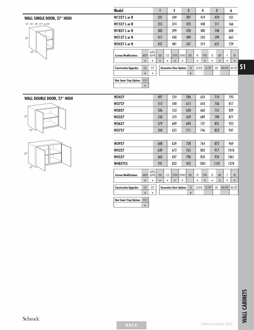
WALL SINGLE DOOR, 27″ HIGH
12”
27”
12”, 15”, 18”, 21”, or 24”
Model 1 2 3 4 5 6
W1227 L or R 331 349 397 419 479 531
W1527 L or R 355 374 425 448 511 566
W1827 L or R 383 399 458 480 548 608
W2127 L or R 417 440 499 524 599 665
W2427 L or R 457 481 547 574 657 729
Custom Modifications ADDTKAUTHLAUTHR CBO CCO CFNTO CFRMO CND FB FPEB ID MIP P RD
• • • • • • • • • • • •
Construction Upgrades ECA ECP
• •
Decorative Door Options CG CG.BTM CG.TOP MD MD.BTM MD.TOP
•
Non Smart Stop Options NSCH
•
WALL DOUBLE DOOR, 27″ HIGH
12”
27”
12”
27”
W2427 497 524 596 624 714 793
W2727 512 540 615 643 736 817
W3027 526 553 630 660 755 839
W3327 550 579 659 689 790 877
W3627 579 609 694 727 831 923
W3727 594 625 711 746 852 947
W3927 608 639 728 764 872 969
W4227 639 672 765 803 917 1018
W4527 663 697 796 834 954 1061
W4827CS 791 832 952 1001 1147 1278
Custom Modifications ADDTKAUTHLAUTHR CBO CCO CFNTO CFRMO CND FB FPEB ID MIP P RD
• • • • • • • • • • • •
Construction Upgrades ECA ECP
• •
Decorative Door Options CG CG.BTM CG.TOP MD MD.BTM MD.TOP
•
Non Smart Stop Options NSCH
•
WAL
LCAB
INET
S
51
Effective March 2020

WALL REFRIGERATOR DOUBLE DOOR,27″ HIGH, 24″ DEEP
24”
27”
24”
27”
Model 1 2 3 4 5 6
W302724 642 675 770 807 922 1023
W332724 670 704 806 841 963 1069
W362724 705 741 846 887 1015 1127
W372724 723 760 867 911 1041 1156
W392724 740 780 889 933 1067 1185
W422724 779 817 933 979 1119 1243
W452724 809 851 970 1016 1163 1293
W482724CS 890 935 1067 1118 1280 1422
• 24″ deep cabinets must be fully supported by screws installed in a structural member in the ceiling or soffit, and into adjacent cabinets.• Load limit is 15 lbs. per square foot of load bearing surface.
Custom Modifications ADDTKAUTHLAUTHR CBO CCO CFNTO CFRMO CND FB FPEB ID MIP P RD
• • • • • • • • • •
Construction Upgrades ECA ECP
• •
Decorative Door Options CG CG.BTM CG.TOP MD MD.BTM MD.TOP
•
Non Smart Stop Options NSCH
•
WALL SINGLE DOOR, 30″ HIGH
30”
12”
W930 L or R 321 339 385 403 462 514
W1230 L or R 343 362 411 429 493 547
W1530 L or R 365 385 441 461 527 584
W1830 L or R 393 413 473 494 564 626
W2130 L or R 427 452 515 540 617 685
W2430 L or R 465 490 558 585 667 741
• MD not available on W930 L or R and W1230 L or R.
Custom Modifications ADDTKAUTHLAUTHR CBO CCO CFNTO CFRMO CND FB FPEB ID MIP P RD
• • • • • • • • • • • •
Construction Upgrades ECA ECP
• •
Decorative Door Options CG CG.BTM CG.TOP MD MD.BTM MD.TOP
• •
Non Smart Stop Options NSCH
•
WAL
LCAB
INET
S
52
Effective March 2020

WALL DOUBLE DOOR, 30″ HIGH
30”
12”
30”
12”
Model 1 2 3 4 5 6
W2430 513 540 616 644 737 817
W2730 527 557 632 663 758 843
W3030 555 583 663 695 795 882
W3330 579 609 694 727 831 923
W3630 606 639 728 764 872 969
W3930 639 674 766 805 919 1020
W4230 671 706 806 845 966 1072
W4530 730 768 877 918 1050 1167
W4830CS 832 878 1007 1053 1210 1346
• MD not available on W3930.
Custom Modifications ADDTKAUTHLAUTHR CBO CCO CFNTO CFRMO CND FB FPEB ID MIP P RD
• • • • • • • • • • • •
Construction Upgrades ECA ECP
• •
Decorative Door Options CG CG.BTM CG.TOP MD MD.BTM MD.TOP
• •
Non Smart Stop Options NSCH
•
WALL SINGLE DOOR, 33″ HIGH
33”
12”
9”, 12”, 15”, 18”, 21”, or 24”
W933 L or R 357 376 429 449 515 572
W1233 L or R 383 402 456 479 549 608
W1533 L or R 408 428 489 513 586 652
W1833 L or R 438 461 525 551 630 700
W2133 L or R 477 501 572 600 688 762
W2433 L or R 518 544 621 652 744 827
• MD not available on W933 L or R and W1233 L or R.
Custom Modifications ADDTKAUTHLAUTHR CBO CCO CFNTO CFRMO CND FB FPEB ID MIP P RD
• • • • • • • • • • • •
Construction Upgrades ECA ECP
• •
Decorative Door Options CG CG.BTM CG.TOP MD MD.BTM MD.TOP
• •
Non Smart Stop Options NSCH
•
WAL
LCAB
INET
S
53
Effective March 2020

WALL DOUBLE DOOR, 33″ HIGH
33”
12”
24”, 27”, 30”, 33”, or 36”
W2433W2733W3033W3333W3633
33”
12”
39”, 42”, 45”, or 48”
W3933W4233W4533W4833CS
Model 1 2 3 4 5 6
W2433 578 605 692 725 829 920
W2733 597 627 713 749 857 952
W3033 625 657 748 784 898 997
W3333 653 686 782 819 937 1042
W3633 686 721 823 863 986 1095
W3933 741 780 889 932 1066 1185
W4233 778 820 933 979 1121 1246
W4533 847 893 1015 1064 1218 1356
W4833CS 971 1024 1168 1226 1408 1568
• MD not available on W3933.
Custom Modifications ADDTKAUTHLAUTHR CBO CCO CFNTO CFRMO CND FB FPEB ID MIP P RD
• • • • • • • • • • • •
Construction Upgrades ECA ECP
• •
Decorative Door Options CG CG.BTM CG.TOP MD MD.BTM MD.TOP
• •
Non Smart Stop Options NSCH
•
WALL SINGLE DOOR, 36″ HIGH
36”
12”
W936 L or R 365 385 441 461 528 587
W1236 L or R 392 412 467 491 562 624
W1536 L or R 419 440 500 525 601 668
W1836 L or R 448 475 539 564 646 719
W2136 L or R 488 515 587 616 705 781
W2436 L or R 530 558 637 668 763 848
• MD not available on W936 L or R and W1236 L or R.
Custom Modifications ADDTKAUTHLAUTHR CBO CCO CFNTO CFRMO CND FB FPEB ID MIP P RD
• • • • • • • • • • • •
Construction Upgrades ECA ECP
• •
Decorative Door Options CG CG.BTM CG.TOP MD MD.BTM MD.TOP
• •
Non Smart Stop Options NSCH
•
WAL
LCAB
INET
S
54
Effective March 2020
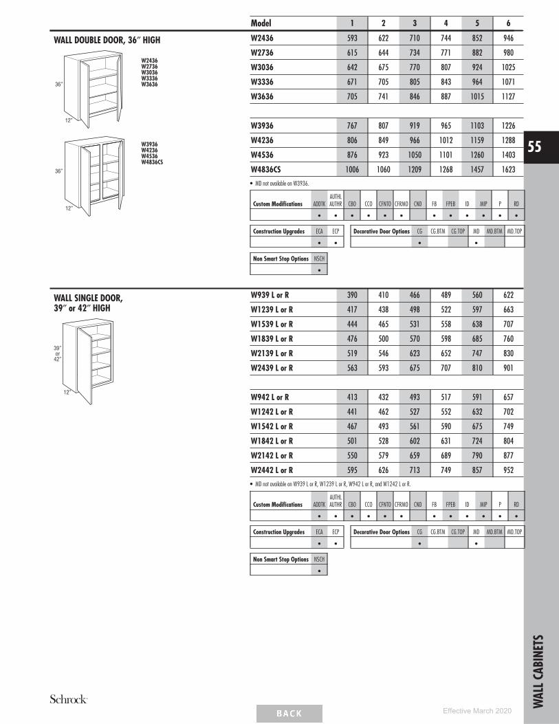
WALL DOUBLE DOOR, 36″ HIGH
36”
12”
W2436W2736W3036W3336W3636
36”
12”
W3936W4236W4536W4836CS
Model 1 2 3 4 5 6
W2436 593 622 710 744 852 946
W2736 615 644 734 771 882 980
W3036 642 675 770 807 924 1025
W3336 671 705 805 843 964 1071
W3636 705 741 846 887 1015 1127
W3936 767 807 919 965 1103 1226
W4236 806 849 966 1012 1159 1288
W4536 876 923 1050 1101 1260 1403
W4836CS 1006 1060 1209 1268 1457 1623
• MD not available on W3936.
Custom Modifications ADDTKAUTHLAUTHR CBO CCO CFNTO CFRMO CND FB FPEB ID MIP P RD
• • • • • • • • • • • •
Construction Upgrades ECA ECP
• •
Decorative Door Options CG CG.BTM CG.TOP MD MD.BTM MD.TOP
• •
Non Smart Stop Options NSCH
•
WALL SINGLE DOOR,39″ or 42″ HIGH
39”or
42”
12”
W939 L or R 390 410 466 489 560 622
W1239 L or R 417 438 498 522 597 663
W1539 L or R 444 465 531 558 638 707
W1839 L or R 476 500 570 598 685 760
W2139 L or R 519 546 623 652 747 830
W2439 L or R 563 593 675 707 810 901
W942 L or R 413 432 493 517 591 657
W1242 L or R 441 462 527 552 632 702
W1542 L or R 467 493 561 590 675 749
W1842 L or R 501 528 602 631 724 804
W2142 L or R 550 579 659 689 790 877
W2442 L or R 595 626 713 749 857 952
• MD not available on W939 L or R, W1239 L or R, W942 L or R, and W1242 L or R.
Custom Modifications ADDTKAUTHLAUTHR CBO CCO CFNTO CFRMO CND FB FPEB ID MIP P RD
• • • • • • • • • • • •
Construction Upgrades ECA ECP
• •
Decorative Door Options CG CG.BTM CG.TOP MD MD.BTM MD.TOP
• •
Non Smart Stop Options NSCH
•
WAL
LCAB
INET
S
55
Effective March 2020

WALL DOUBLE DOOR,39″ or 42″ HIGH
39”or
42”
12”
W2439 W2442W2739 W2742W3039 W3042W3339 W3342W3639 W3642
39”or
42”
12”
W3939 W3942W4239 W4242W4539 W4542W4839CS W4842CS
Model 1 2 3 4 5 6
W2439 632 665 757 794 909 1010
W2739 655 688 784 824 942 1047
W3039 686 722 823 863 987 1096
W3339 716 755 860 903 1031 1146
W3639 755 793 906 948 1085 1205
W2442 672 706 806 844 966 1072
W2742 697 733 836 876 1003 1115
W3042 729 768 876 917 1050 1166
W3342 761 805 913 960 1098 1220
W3642 804 844 964 1010 1155 1284
W3939 814 857 979 1024 1172 1303
W4239 856 903 1027 1075 1232 1369
W4539 932 982 1117 1171 1340 1490
W4839CS 1070 1128 1287 1350 1550 1724
W3942 864 908 1036 1083 1241 1382
W4242 907 954 1088 1140 1305 1448
W4542 987 1039 1183 1241 1419 1576
W4842CS 1134 1195 1364 1433 1642 1827
• MD not available on W3939 and W3942.
Custom Modifications ADDTKAUTHLAUTHR CBO CCO CFNTO CFRMO CND FB FPEB ID MIP P RD
• • • • • • • • • • • •
Construction Upgrades ECA ECP
• •
Decorative Door Options CG CG.BTM CG.TOP MD MD.BTM MD.TOP
• •
Non Smart Stop Options NSCH
•
WAL
LCAB
INET
S
56
Effective March 2020

STACKED WALL CABINETS SINGLE DOOR,48″, 51″, 54″, 57″, or 60″ HIGH
15” FrameOpeningHeight
12”, 15”, 18”, 21”, or 24”
12”
27”, 30”, or 33”FrameOpeningHeight
48”
or51”
54”
12”
12”, 15”, 18”, 21”, or 24”
15” FrameOpeningHeight
36” or 39”FrameOpeningHeight
or57”
60”
Model 1 2 3 4 5 6
STW1248 L or R 790 834 948 991 1136 1260
STW1548 L or R 839 884 1013 1060 1210 1341
STW1848 L or R 896 945 1079 1130 1289 1430
STW2148 L or R 965 1019 1164 1218 1391 1545
STW2448 L or R 1016 1071 1223 1283 1461 1623
STW1251 L or R 840 884 1004 1054 1206 1336
STW1551 L or R 893 938 1073 1125 1284 1426
STW1851 L or R 953 1005 1144 1201 1371 1523
STW2151 L or R 1028 1080 1235 1293 1480 1641
STW2451 L or R 1083 1139 1301 1366 1558 1730
STW1254 L or R 851 896 1018 1069 1223 1356
STW1554 L or R 906 953 1086 1140 1303 1446
STW1854 L or R 965 1023 1161 1218 1391 1546
STW2154 L or R 1041 1098 1254 1313 1501 1665
STW2454 L or R 1098 1156 1321 1386 1581 1756
STW1257 L or R 883 929 1056 1108 1266 1405
STW1557 L or R 938 984 1125 1181 1349 1495
STW1857 L or R 1000 1054 1200 1260 1440 1598
STW2157 L or R 1080 1136 1299 1358 1554 1726
STW2457 L or R 1139 1200 1369 1435 1640 1823
STW1260 L or R 913 959 1093 1145 1310 1454
STW1560 L or R 966 1019 1163 1221 1395 1548
STW1860 L or R 1031 1089 1240 1301 1489 1653
STW2160 L or R 1119 1178 1344 1404 1608 1785
STW2460 L or R 1179 1241 1416 1488 1699 1886
• MD.BTM, MD.TOP not available on STW12_ _L or R, STW21_ _L or R, and STW24_ _L or R.
Custom Modifications ADDTKAUTHLAUTHR CBO CCO CFNTO CFRMO CND FB FPEB ID MIP P RD
• • • • • • • • • • • •
Construction Upgrades ECA ECP
• •
Decorative Door Options CG CG.BTM CG.TOP MD MD.BTM MD.TOP
• • • •
Non Smart Stop Options NSCH
•W
ALLC
ABIN
ETS
57
Effective March 2020

STACKED WALL CABINETS DOUBLE DOOR,48″, 51″, 54″, 57″, or 60″ HIGH
24”, 27”, 30”, 33”, or 36”
12”
15” FrameOpeningHeight
27”, 30”, or 33”FrameOpeningHeight
48”
or51”
54”
39” or 42”
12”
15” FrameOpeningHeight
27”, 30”, or 33”FrameOpeningHeight
48”
or51”
54”
Model 1 2 3 4 5 6
STW2448 1121 1179 1345 1409 1613 1790
STW2748 1154 1218 1384 1451 1659 1844
STW3048 1215 1276 1453 1523 1743 1934
STW3348 1265 1330 1516 1590 1818 2021
STW3648 1329 1399 1594 1671 1910 2121
STW2451 1203 1260 1440 1510 1728 1919
STW2751 1241 1305 1485 1559 1783 1980
STW3051 1303 1369 1559 1634 1871 2078
STW3351 1358 1426 1626 1705 1950 2170
STW3651 1429 1501 1713 1795 2053 2279
STW2454 1221 1281 1463 1534 1756 1951
STW2754 1264 1326 1511 1586 1814 2015
STW3054 1324 1391 1586 1663 1904 2113
STW3354 1380 1450 1655 1735 1984 2206
STW3654 1453 1526 1741 1825 2089 2319
STW3948 1399 1471 1675 1759 2010 2233
STW4248 1469 1544 1763 1846 2114 2346
STW3951 1526 1604 1829 1918 2194 2439
STW4251 1603 1686 1921 2014 2308 2564
STW3954 1559 1638 1866 1959 2240 2490
STW4254 1638 1723 1963 2055 2355 2616
• P not available on STW3948, STW4248, STW3951, STW4251, STW3954, and STW4254.• MD.BTM and MD.TOP only available on STW3048, STW3648, STW3051, STW3651, STW3054, and STW3654.
Custom Modifications ADDTKAUTHLAUTHR CBO CCO CFNTO CFRMO CND FB FPEB ID MIP P RD
• • • • • • • • • • • •
Construction Upgrades ECA ECP
• •
Decorative Door Options CG CG.BTM CG.TOP MD MD.BTM MD.TOP
• • • •
Non Smart Stop Options NSCH
•
WAL
LCAB
INET
S
58
Effective March 2020

STACKED WALL CABINETS DOUBLE DOOR,48″, 51″, 54″, 57″, or 60″ HIGH (cont’d)
24”, 27”, 30”, 33”, or 36”
12”
15” FrameOpeningHeight
36” or 39”FrameOpeningHeight
or57”
60”
39” or 42”
12”
15” FrameOpeningHeight
36” or 39”FrameOpeningHeight
or57”
60”
Model 1 2 3 4 5 6
STW2457 1270 1335 1521 1596 1828 2031
STW2757 1314 1381 1574 1653 1889 2099
STW3057 1379 1450 1653 1733 1983 2201
STW3357 1436 1513 1724 1810 2068 2300
STW3657 1515 1591 1816 1901 2176 2416
STW2460 1320 1386 1583 1659 1899 2109
STW2760 1366 1438 1639 1718 1965 2184
STW3060 1433 1508 1719 1800 2061 2289
STW3360 1493 1575 1790 1881 2151 2393
STW3660 1576 1655 1889 1979 2264 2515
STW3957 1618 1700 1941 2033 2326 2586
STW4257 1700 1790 2039 2134 2446 2718
STW3960 1680 1764 2013 2106 2413 2685
STW4260 1764 1854 2115 2215 2538 2816
• P not available on STW3957, STW4257, STW3960, and STW4260.• MD.BTM and MD.TOP only available on SSTW3057, STW3657, STW3060, and STW3660.
Custom Modifications ADDTKAUTHLAUTHR CBO CCO CFNTO CFRMO CND FB FPEB ID MIP P RD
• • • • • • • • • • • •
Construction Upgrades ECA ECP
• •
Decorative Door Options CG CG.BTM CG.TOP MD MD.BTM MD.TOP
• • • •
Non Smart Stop Options NSCH
•
WAL
LCAB
INET
S
59
Effective March 2020

WALL THREE DRAWER SINGLE DOOR,48″, 51″, 54″, 57″, or 60″ HIGH
48”51”or
54”
12”
18”
12”
57”or
60”
15”, 18”, or 24”
18”
W3D1548 L or RW3D1848 L or RW3D2448 L or R
W3D1551 L or RW3D1851 L or RW3D2451 L or R
W3D1554 L or RW3D1854 L or RW3D2454 L or R
W3D1557 L or RW3D1857 L or RW3D2457 L or R
W3D1560 L or RW3D1860 L or RW3D2460 L or R
Model 1 2 3 4 5 6
W3D1548 L or R 1078 1105 1165 1198 1312 1418
W3D1848 L or R 1121 1148 1213 1248 1371 1486
W3D2448 L or R 1234 1268 1348 1389 1531 1662
W3D1551 L or R 1143 1173 1242 1277 1403 1521
W3D1851 L or R 1189 1224 1297 1336 1471 1598
W3D2451 L or R 1315 1352 1443 1492 1648 1793
W3D1554 L or R 1159 1189 1260 1296 1427 1546
W3D1854 L or R 1207 1243 1319 1358 1496 1625
W3D2454 L or R 1335 1372 1468 1517 1677 1825
W3D1557 L or R 1200 1231 1305 1346 1483 1610
W3D1857 L or R 1248 1286 1367 1409 1556 1691
W3D2457 L or R 1385 1427 1529 1580 1750 1907
W3D1560 L or R 1238 1272 1354 1397 1541 1673
W3D1860 L or R 1289 1328 1417 1462 1617 1756
W3D2460 L or R 1434 1481 1587 1642 1823 1987
• Includes one shallow depth drawer and two standard drawers with undermount Smart Stop guides.• Top drawer will be slab drawer front for all 5-piece drawer applications.• Drawer front to face frame reveal is justified to the top to be consistent with both full and partial overlay. Bottom reveal is 7/8″ for full overlay and
1″ for partial overlay.
Custom Modifications ADDTKAUTHLAUTHR CBO CCO CFNTO CFRMO CND FB FPEB ID MIP P RD
• • • • • • • • •
Construction Upgrades ECA ECP
• •
Decorative Door Options CG CG.BTM CG.TOP MD MD.BTM MD.TOP
• •
Non Smart Stop Options NSCH
•
WAL
LCAB
INET
S
60
Effective March 2020

WALL THREE DRAWER DOUBLE DOOR,48″, 51″, 54″, 57″, or 60″ HIGH
48”51”or
54”
12”
18”
57”or
60”
12”
24”
18”
W3D2448W3D2451W3D2454
W3D2457W3D2460
Model 1 2 3 4 5 6
W3D2448 1305 1345 1436 1481 1635 1779
W3D2451 1404 1445 1554 1605 1778 1938
W3D2454 1430 1471 1583 1636 1814 1979
W3D2457 1492 1539 1658 1715 1903 2077
W3D2460 1553 1604 1732 1792 1993 2173
• Includes one shallow depth drawer and two standard drawers with undermount Smart Stop guides.• Top drawer will be slab drawer front for all 5-piece drawer applications.• Drawer front to face frame reveal is justified to the top to be consistent with both full and partial overlay. Bottom reveal is 7/8″ for full overlay and
1″ for partial overlay.
Custom Modifications ADDTKAUTHLAUTHR CBO CCO CFNTO CFRMO CND FB FPEB ID MIP P RD
• • • • • • • • •
Construction Upgrades ECA ECP
• •
Decorative Door Options CG CG.BTM CG.TOP MD MD.BTM MD.TOP
• •
Non Smart Stop Options NSCH
•
WAL
LCAB
INET
S
61
Effective March 2020
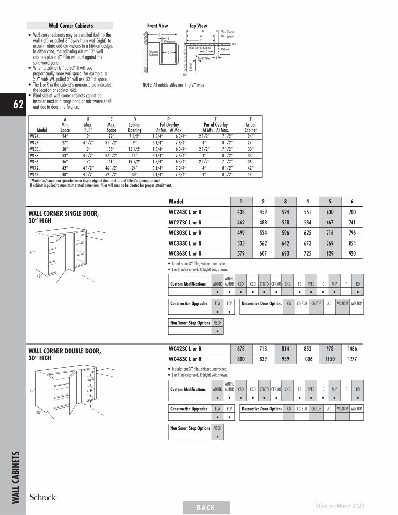
Wall Corner Cabinets• Wall corner cabinets may be installed flush to the
wall (left) or pulled 3″ away from wall (right) toaccommodate odd dimensions in a kitchen design.In either case, the adjoining run of 12″ wallcabinets plus a 3″ filler will butt against thesolid-wood panel.
• When a cabinet is ‘‘pulled’’ it will useproportionally more wall space, for example, a30″ wide WC pulled 2″ will use 32″ of space.
• The L or R in the cabinet’s nomenclature indicatesthe location of cabinet void.
• Blind side of wall corner cabinets cannot beinstalled next to a range hood or microwave shelfunit due to door interference.
Front View Top ViewC
AMax. Space
Min. Space
CabinetWall Corner Cabinet
Cabi
net
Wall
Wall
3” Filler
F
B
D
C
D
E
AdjacentCabinet
Clearance
E
NOTE: All outside stiles are 1 1/2″ wide
Model
AMin.
Space
BMax.Pull*
CMax.Space
DCabinetOpening
E*Full Overlay
At Min. At Max.
EPartial Overlay
At Min. At Max.
FActual
CabinetWC24.. 24″ 5″ 29″ 7 1/2″ 1 3/4″ 6 3/4″ 2 1/2″ 7 1/2″ 24″WC27.. 27″ 4 1/2″ 31 1/2″ 9″ 3 1/4″ 7 3/4″ 4″ 8 1/2″ 27″WC30.. 30″ 5″ 35″ 13 1/2″ 1 3/4″ 6 3/4″ 2 1/2″ 7 1/2″ 30″WC33.. 33″ 4 1/2″ 37 1/2″ 15″ 3 1/4″ 7 3/4″ 4″ 8 1/2″ 33″WC36.. 36″ 5″ 41″ 19 1/2″ 1 3/4″ 6 3/4″ 2 1/2″ 7 1/2″ 36″WC42.. 42″ 4 1/2″ 46 1/2″ 24″ 3 1/4″ 7 3/4″ 4″ 8 1/2″ 42″WC48.. 48″ 4 1/2″ 52 1/2″ 30″ 3 1/4″ 7 3/4″ 4″ 8 1/2″ 48″*Minimum/maximum space between inside edge of door and face of filler/adjoining cabinet.If cabinet is pulled to maximum stated dimension, filler will need to be cleated for proper attachment.
WALL CORNER SINGLE DOOR,30″ HIGH
12”
30”
Model 1 2 3 4 5 6
WC2430 L or R 438 459 524 551 630 700
WC2730 L or R 462 488 558 584 667 741
WC3030 L or R 499 524 596 625 716 796
WC3330 L or R 535 562 642 673 769 854
WC3630 L or R 579 607 693 725 829 920
• Includes one 3″ filler, shipped unattached.• L or R indicates void. R (right) void shown.
Custom Modifications ADDTKAUTHLAUTHR CBO CCO CFNTO CFRMO CND FB FPEB ID MIP P RD
• • • • • • • • • • •
Construction Upgrades ECA ECP
• •
Decorative Door Options CG CG.BTM CG.TOP MD MD.BTM MD.TOP
Non Smart Stop Options NSCH
•
WALL CORNER DOUBLE DOOR,30″ HIGH
12”
30”
WC4230 L or R 678 713 814 853 978 1086
WC4830 L or R 800 839 959 1006 1150 1277
• Includes one 3″ filler, shipped unattached.• L or R indicates void. R (right) void shown.
Custom Modifications ADDTKAUTHLAUTHR CBO CCO CFNTO CFRMO CND FB FPEB ID MIP P RD
• • • • • • • • • • •
Construction Upgrades ECA ECP
• •
Decorative Door Options CG CG.BTM CG.TOP MD MD.BTM MD.TOP
Non Smart Stop Options NSCH
•
WAL
LCAB
INET
S
62
Effective March 2020

WALL CORNER SINGLE DOOR,33″ HIGH
12”
33”
24”, 27”, 30”, 33”, or 36”
Model 1 2 3 4 5 6
WC2433 L or R 489 515 587 616 705 783
WC2733 L or R 520 548 625 655 748 832
WC3033 L or R 558 587 668 701 802 890
WC3333 L or R 601 632 722 756 863 960
WC3633 L or R 647 679 775 812 929 1033
• Includes one 3″ filler, shipped unattached.• L or R indicates void. R (right) void shown.
Custom Modifications ADDTKAUTHLAUTHR CBO CCO CFNTO CFRMO CND FB FPEB ID MIP P RD
• • • • • • • • • • •
Construction Upgrades ECA ECP
• •
Decorative Door Options CG CG.BTM CG.TOP MD MD.BTM MD.TOP
Non Smart Stop Options NSCH
•
WALL CORNER SINGLE DOOR,36″ HIGH
36”
12”
WC2436 L or R 501 528 602 631 724 804
WC2736 L or R 533 562 641 672 768 853
WC3036 L or R 572 602 687 720 823 913
WC3336 L or R 618 650 741 776 888 987
WC3636 L or R 663 697 796 834 954 1061
• Includes one 3″ filler, shipped unattached.• L or R indicates void. R (right) void shown.
Custom Modifications ADDTKAUTHLAUTHR CBO CCO CFNTO CFRMO CND FB FPEB ID MIP P RD
• • • • • • • • • • •
Construction Upgrades ECA ECP
• •
Decorative Door Options CG CG.BTM CG.TOP MD MD.BTM MD.TOP
Non Smart Stop Options NSCH
•
WALL CORNER SINGLE DOOR,39″ or 42″ HIGH
39”or
42”
12”
WC2439 L or R 535 563 642 674 770 854
WC2739 L or R 569 598 683 715 819 910
WC3039 L or R 610 642 732 766 878 973
WC3339 L or R 658 694 790 827 947 1050
WC3639 L or R 706 743 848 888 1016 1128
WC2442 L or R 566 598 680 714 818 908
WC2742 L or R 603 637 724 758 867 965
WC3042 L or R 647 679 776 812 931 1034
WC3342 L or R 699 735 837 878 1004 1116
WC3642 L or R 750 788 900 943 1078 1198
• Includes one 3″ filler, shipped unattached.• L or R indicates void. R (right) void shown.
Custom Modifications ADDTKAUTHLAUTHR CBO CCO CFNTO CFRMO CND FB FPEB ID MIP P RD
• • • • • • • • • • •
Construction Upgrades ECA ECP
• •
Decorative Door Options CG CG.BTM CG.TOP MD MD.BTM MD.TOP
Non Smart Stop Options NSCH
•
WAL
LCAB
INET
S
63
Effective March 2020

DIAGONAL WALL, 12″, 15″, or 18″ HIGH,24″ x 24″
24”
12”
24”12”15”or
18”
Model 1 2 3 4 5 6
DW122424 L or R 542 573 665 701 812 911
DW152424 L or R 552 583 675 711 822 921
DW182424 L or R 561 593 685 721 831 931
• Cabinets require 24″ x 24″ of corner wall space.• Full overlay styles use the same width doors as partial overlay styles (14 1/2″ wide) with a partial overlay hinge (38NPOHINGE) to allow for proper
door clearance with adjacent cabinets.
Custom Modifications ADDTKAUTHLAUTHR CBO CCO CFNTO CFRMO CND FB FPEB ID MIP P RD
• • • • • • •
Construction Upgrades ECA ECP
• •
Decorative Door Options CG CG.BTM CG.TOP MD MD.BTM MD.TOP
•
Non Smart Stop Options NSCH
•
DIAGONAL WALL, 24″ or 27″ HIGH,24″ x 24″
24”
12”
24”
24”or
27”
DW242424 L or R 581 613 704 740 851 950
DW272424 L or R 600 632 724 760 870 970
• Cabinets require 24″ x 24″ of corner wall space.• Adjustable shelf cannot be removed/retrofitted.• Full overlay styles use the same width doors as partial overlay styles (14 1/2″ wide) with a partial overlay hinge (38NPOHINGE) to allow for proper
door clearance with adjacent cabinets.
Custom Modifications ADDTKAUTHLAUTHR CBO CCO CFNTO CFRMO CND FB FPEB ID MIP P RD
• • • • • • • •
Construction Upgrades ECA ECP
• •
Decorative Door Options CG CG.BTM CG.TOP MD MD.BTM MD.TOP
•
Non Smart Stop Options NSCH
•
DIAGONAL WALL, 30″, 33″, 36″, 39″,or 42″ HIGH, 24″ x 24″
24”
12”
24”
30”33”or
36”
24”
12”
24”
12”
39”or
42”
DW302424 L or RDW332424 L or RDW362424 L or R
DW392424 L or RDW422424 L or R
DW302424 L or R 620 652 743 779 890 989
DW332424 L or R 695 731 833 873 997 1108
DW362424 L or R 713 750 854 897 1024 1139
DW392424 L or R 759 800 911 954 1093 1213
DW422424 L or R 806 849 966 1012 1159 1287
• Cabinets require 24″ x 24″ of corner wall space.• Full overlay styles use the same width doors as partial overlay styles (14 1/2″ wide) with a partial overlay hinge (38NPOHINGE) to allow for proper
door clearance with adjacent cabinets.
Custom Modifications ADDTKAUTHLAUTHR CBO CCO CFNTO CFRMO CND FB FPEB ID MIP P RD
• • • • • • • •
Construction Upgrades ECA ECP
• •
Decorative Door Options CG CG.BTM CG.TOP MD MD.BTM MD.TOP
• •
Non Smart Stop Options NSCH
•
WAL
LCAB
INET
S
64
Effective March 2020

DIAGONAL WALL, 15″ or 18″ HIGH,27″ x 27″
27”
15”
27”
15”or
18”
Model 1 2 3 4 5 6
DW152727 L or R 600 634 734 773 893 1001
DW182727 L or R 610 645 745 784 903 1012
• Cabinets require 27″ x 27″ of corner wall space.• Full overlay styles use the same width doors as partial overlay styles (14 1/2″ wide) with a partial overlay hinge (38NPOHINGE) to allow for proper
door clearance with adjacent cabinets.
Custom Modifications ADDTKAUTHLAUTHR CBO CCO CFNTO CFRMO CND FB FPEB ID MIP P RD
• • • • • • •
Construction Upgrades ECA ECP
• •
Decorative Door Options CG CG.BTM CG.TOP MD MD.BTM MD.TOP
•
Non Smart Stop Options NSCH
•
DIAGONAL WALL, 24″ or 27″ HIGH,27″ x 27″
27”
15”
27”
or27”
24”
DW242727 L or R 632 666 765 804 925 1033
DW272727 L or R 652 687 787 826 946 1054
• Cabinets require 27″ x 27″ of corner wall space.• Adjustable shelf cannot be removed/retrofitted.• Full overlay styles use the same width doors as partial overlay styles (14 1/2″ wide) with a partial overlay hinge (38NPOHINGE) to allow for proper
door clearance with adjacent cabinets.
Custom Modifications ADDTKAUTHLAUTHR CBO CCO CFNTO CFRMO CND FB FPEB ID MIP P RD
• • • • • • • •
Construction Upgrades ECA ECP
• •
Decorative Door Options CG CG.BTM CG.TOP MD MD.BTM MD.TOP
•
Non Smart Stop Options NSCH
•
DIAGONAL WALL, 30″, 33″, 36″, 39″,or 42″ HIGH, 27″ x 27″
27”
15”
27”
30”33”or
36”
27”
15” 15”
27”
39”or
42”
DW302727 L or RDW332727 L or RDW362727 L or R
DW392727 L or RDW422727 L or R
DW302727 L or R 675 709 809 846 968 1076
DW332727 L or R 755 794 906 949 1084 1204
DW362727 L or R 775 814 931 974 1112 1236
DW392727 L or R 826 870 991 1039 1188 1320
DW422727 L or R 876 921 1050 1102 1259 1400
• Cabinets require 27″ x 27″ of corner wall space.• Full overlay styles use the same width doors as partial overlay styles (14 1/2″ wide) with a partial overlay hinge (38NPOHINGE) to allow for proper
door clearance with adjacent cabinets.
Custom Modifications ADDTKAUTHLAUTHR CBO CCO CFNTO CFRMO CND FB FPEB ID MIP P RD
• • • • • • • •
Construction Upgrades ECA ECP
• •
Decorative Door Options CG CG.BTM CG.TOP MD MD.BTM MD.TOP
• •
Non Smart Stop Options NSCH
•W
ALLC
ABIN
ETS
65
Effective March 2020

STACKED DIAGONAL WALL,48″, 51″, 54″, 57″, or 60″ HIGH,24″ x 24″
12”
48”51”or
54”
24” 24”
12”
15” FrameOpeningHeight
27”, 30”, or 33” FrameOpeningHeight
12”
57”or
60”
24” 24”
12”
15” FrameOpeningHeight
36” or 39”FrameOpeningHeight
STDW482424 L or RSTDW512424 L or RSTDW542424 L or R
STDW572424 L or RSTDW602424 L or R
Model 1 2 3 4 5 6
STDW482424 L or R 1476 1556 1785 1875 2151 2400
STDW512424 L or R 1570 1655 1898 1993 2285 2549
STDW542424 L or R 1593 1679 1924 2023 2319 2588
STDW572424 L or R 1650 1741 1995 2094 2405 2680
STDW602424 L or R 1709 1803 2064 2166 2488 2773
• Cabinet requires 24″ x 24″ of corner wall space.• Full overlay styles use the same width doors as partial overlay styles (14 1/2″ wide) with a partial overlay hinge (38NPOHINGE) to allow for proper
door clearance with adjacent cabinets.
Custom Modifications ADDTKAUTHLAUTHR CBO CCO CFNTO CFRMO CND FB FPEB ID MIP P RD
• • • • • • • •
Construction Upgrades ECA ECP
• •
Decorative Door Options CG CG.BTM CG.TOP MD MD.BTM MD.TOP
• •
Non Smart Stop Options NSCH
•
STACKED DIAGONAL WALL,48″, 51″, 54″, 57″, or 60″ HIGH,27″ x 27″
15”
27” 27”
15”
15” FrameOpeningHeight
27”, 30”, or 33” FrameOpeningHeight
48”51”or
54”
15”
57”or
60”
27” 27”
15”
15” FrameOpeningHeight
36” or 39”FrameOpeningHeight
STDW482727 L or RSTDW512727 L or RSTDW542727 L or R
STDW572727 L or RSTDW602727 L or R
STDW482727 L or R 1606 1693 1943 2038 2339 2610
STDW512727 L or R 1706 1799 2064 2166 2484 2770
STDW542727 L or R 1731 1824 2095 2198 2519 2810
STDW572727 L or R 1795 1894 2170 2279 2614 2915
STDW602727 L or R 1858 1958 2244 2358 2703 3015
• Cabinet requires 27″ x 27″ of corner wall space.• Full overlay styles use the same width doors as partial overlay styles (14 1/2″ wide) with a partial overlay hinge (38NPOHINGE) to allow for proper
door clearance with adjacent cabinets.
Custom Modifications ADDTKAUTHLAUTHR CBO CCO CFNTO CFRMO CND FB FPEB ID MIP P RD
• • • • • • • •
Construction Upgrades ECA ECP
• •
Decorative Door Options CG CG.BTM CG.TOP MD MD.BTM MD.TOP
• •
Non Smart Stop Options NSCH
•
DIAGONAL WALL with PLYWOODLAZY SUSAN, 30″, 33″, 36″, 39″,or 42″ HIGH, 24″ x 24″
24”24”
12”
30”33”or
36”
24”
12” 12”
24”
39”or
42”
DW302424S L or RDW332424S L or RDW362424S L or R
DW392424S L or RDW422424S L or R
DW302424S L or R 1126 1157 1249 1285 1405 1494
DW332424S L or R 1200 1236 1338 1379 1511 1614
DW362424S L or R 1218 1255 1360 1403 1538 1645
DW392424S L or R 1334 1374 1485 1529 1678 1787
DW422424S L or R 1380 1423 1540 1587 1741 1862
• Cabinets require 24″ x 24″ of corner wall space.• Plywood shelves are 18″ in overall diameter with a 17″ interior diameter.• Full overlay styles use the same width doors as partial overlay styles (14 1/2″ wide) with a partial overlay hinge (38NPOHINGE) to allow for proper
door clearance with adjacent cabinets.
Custom Modifications ADDTKAUTHLAUTHR CBO CCO CFNTO CFRMO CND FB FPEB ID MIP P RD
• • • • • • • •
Construction Upgrades ECA ECP
• •
Decorative Door Options CG CG.BTM CG.TOP MD MD.BTM MD.TOP
• •
Non Smart Stop Options NSCH
•
WAL
LCAB
INET
S
66
Effective March 2020
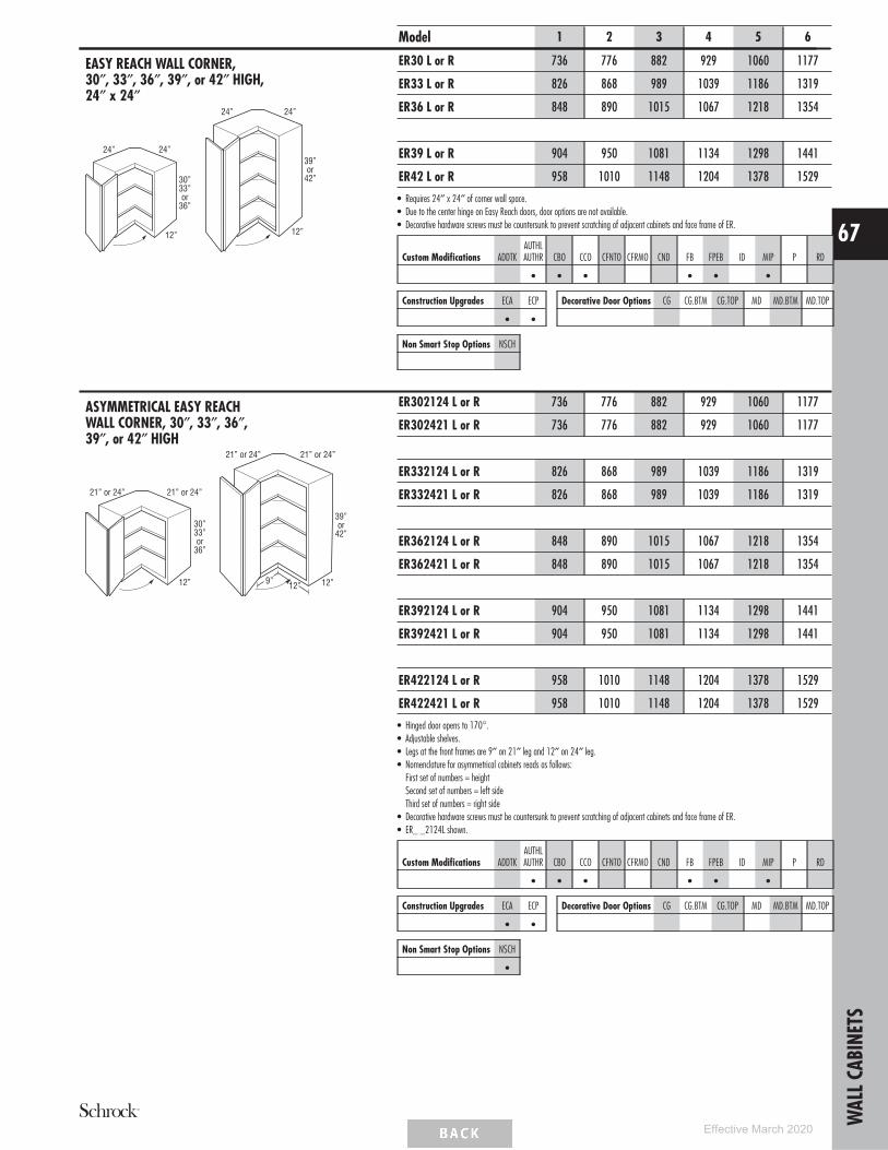
EASY REACH WALL CORNER,30″, 33″, 36″, 39″, or 42″ HIGH,24″ x 24″
24”
12”
24”
30”33”or
36”
24”
12”
24”
39”or
42”
Model 1 2 3 4 5 6
ER30 L or R 736 776 882 929 1060 1177
ER33 L or R 826 868 989 1039 1186 1319
ER36 L or R 848 890 1015 1067 1218 1354
ER39 L or R 904 950 1081 1134 1298 1441
ER42 L or R 958 1010 1148 1204 1378 1529
• Requires 24″ x 24″ of corner wall space.• Due to the center hinge on Easy Reach doors, door options are not available.• Decorative hardware screws must be countersunk to prevent scratching of adjacent cabinets and face frame of ER.
Custom Modifications ADDTKAUTHLAUTHR CBO CCO CFNTO CFRMO CND FB FPEB ID MIP P RD
• • • • • •
Construction Upgrades ECA ECP
• •
Decorative Door Options CG CG.BTM CG.TOP MD MD.BTM MD.TOP
Non Smart Stop Options NSCH
ASYMMETRICAL EASY REACHWALL CORNER, 30″, 33″, 36″,39″, or 42″ HIGH
21” or 24”
12”
21” or 24”
30”33”or
36”
21” or 24”
12”
21” or 24”
12”9”
39”or
42”
ER302124 L or R 736 776 882 929 1060 1177
ER302421 L or R 736 776 882 929 1060 1177
ER332124 L or R 826 868 989 1039 1186 1319
ER332421 L or R 826 868 989 1039 1186 1319
ER362124 L or R 848 890 1015 1067 1218 1354
ER362421 L or R 848 890 1015 1067 1218 1354
ER392124 L or R 904 950 1081 1134 1298 1441
ER392421 L or R 904 950 1081 1134 1298 1441
ER422124 L or R 958 1010 1148 1204 1378 1529
ER422421 L or R 958 1010 1148 1204 1378 1529
• Hinged door opens to 170°.• Adjustable shelves.• Legs at the front frames are 9″ on 21″ leg and 12″ on 24″ leg.• Nomenclature for asymmetrical cabinets reads as follows:
First set of numbers = heightSecond set of numbers = left sideThird set of numbers = right side
• Decorative hardware screws must be countersunk to prevent scratching of adjacent cabinets and face frame of ER.• ER_ _2124L shown.
Custom Modifications ADDTKAUTHLAUTHR CBO CCO CFNTO CFRMO CND FB FPEB ID MIP P RD
• • • • • •
Construction Upgrades ECA ECP
• •
Decorative Door Options CG CG.BTM CG.TOP MD MD.BTM MD.TOP
Non Smart Stop Options NSCH
•
WAL
LCAB
INET
S
67
Effective March 2020

WALL END CABINET SINGLE DOOR,30″, 33″, 36″, 39″, or 42″ HIGH,12″ x 12″
12”
12”17”
Top View(WEC)
12” 12”
30”33”or
36”
39”or42”
12” 12”
17”Diagonal
Front Width
Model 1 2 3 4 5 6
WEC1230 L or R 565 595 677 712 814 905
WEC1233 L or R 634 667 761 797 913 1013
WEC1236 L or R 651 685 781 818 936 1041
WEC1239 L or R 694 729 833 872 998 1107
WEC1242 L or R* 735 773 881 923 1057 1175
• Width at wall: 12″ x 12″.• Cabinet features two unfinished back panels. Must be installed with one back panel adjacent to a cabinet of equal height with the other back
panel attached to the wall.*When ordered with MD, shelves will not align with mullions.
Custom Modifications ADDTKAUTHLAUTHR CBO CCO CFNTO CFRMO CND FB FPEB ID MIP P RD
• • • • •
Construction Upgrades ECA ECP
•
Decorative Door Options CG CG.BTM CG.TOP MD MD.BTM MD.TOP
• •
Non Smart Stop Options NSCH
•
WALL QUARTER ROUND END SHELF,30″, 33″, 36″, 39″, or 42″ HIGHSquare Top and Bottom Panels
12”
5”
5”12”
30”33”or
36”
9”, 10”, or 11”
9”, 10”, or 11”
9”, 10”, or 11”
5”
39”or
42”
12”
813/16” or 99/16”
813/16” or 99/16”
813/16” or 99/16”
813/16” or 99/16”
WQRES630STSB 305 305 305 305 305 305
WQRES633STSB 343 343 343 343 343 343
WQRES636STSB 353 353 353 353 353 353
WQRES639STSB 383 383 383 383 383 383
WQRES642STSB 412 412 412 412 412 412
• Units are reversible.• Veneer on 3/4″ furniture board core with matching interior.
MODIFICATIONS
No modifications available forthese products.
Construction Upgrades ECA ECP
•
WALL MICROWAVE CABINET,18″ HIGH
12”
18”
18 1/2”
MW2718Opening: 24″ w x 14
1/4″ hCabinet: 27″ w x 18″ h
MW3018Opening: 27″ w x 14
1/4″ hCabinet: 30″ w x 18″ h
MW2718 500 500 500 500 500 500
MW3018 527 527 527 527 527 527
• Includes one 3/4″ shelf with six mounting screws. Shelf is veneer plywood. Microwave shelf extends beyond the front of thecabinet by 6 1/2″, for a total shelf depth of 18 1/2″.
• Microwave cabinet must be attached to wall stud and adjacent cabinets on both sides for support.• Matching Interior Plywood (MIP) standard.
Custom Modifications ADDTKAUTHLAUTHR CBO CCO CFNTO CFRMO CND FB FPEB ID MIP P RD
• STD • STD • STD
Construction Upgrades ECA ECP
STD
Decorative Door Options CG CG.BTM CG.TOP MD MD.BTM MD.TOP
Non Smart Stop Options NSCH
WAL
LCAB
INET
S
68
Effective March 2020

WALL MICROWAVE DOUBLE DOORCABINET, 36″ HIGH
24”, 27”, or 30”
181/2”
12” FrameOpening Height
36”
12”
MW2436Opening: 21″ w x 18 3/4″ hCabinet: 24″ w x 36″ h
MW2736Opening: 24″ w x 18 3/4″ hCabinet: 27″ w x 36″ h
MW3036Opening: 27″ w x 18 3/4″ hCabinet: 30″ w x 36″ h
Model 1 2 3 4 5 6
MW2436 1218 1236 1287 1306 1361 1406
MW2736 1333 1355 1409 1431 1490 1540
MW3036 1631 1656 1724 1750 1823 1883
• Includes one 3/4″ shelf with six mounting screws. Shelf is veneer plywood. Microwave shelf extends beyond the front of thecabinet by 6 1/2″, for a total shelf depth of 18 1/2″.
• Microwave cabinet must be attached to wall stud.• When ID is ordered, shelf will not be included with cabinet.• Matching Interior Plywood (MIP) standard.
Custom Modifications ADDTKAUTHLAUTHR CBO CCO CFNTO CFRMO CND FB FPEB ID MIP P RD
• • • • • STD • • STD
Construction Upgrades ECA ECP
STD
Decorative Door Options CG CG.BTM CG.TOP MD MD.BTM MD.TOP
•
Non Smart Stop Options NSCH
•
WALL MICROWAVE DOUBLE DOORCABINET, 39″ HIGH
24”, 27”, or 30”
181/2”
15” FrameOpening Height
39”
12”
MW2439Opening: 21″ w x 18 3/4″ hCabinet: 24″ w x 39″ h
MW2739Opening: 24″ w x 18 3/4″ hCabinet: 27″ w x 39″ h
MW3039Opening: 27″ w x 18 3/4″ hCabinet: 30″ w x 39″ h
MW2439 1333 1355 1409 1431 1490 1540
MW2739 1448 1472 1533 1556 1620 1674
MW3039 1743 1771 1844 1871 1949 2013
• Includes one 3/4″ shelf with six mounting screws. Shelf is veneer plywood. Microwave shelf extends beyond the front of thecabinet by 6 1/2″, for a total shelf depth of 18 1/2″.
• Microwave cabinet must be attached to wall stud.• When ID is ordered, shelf will not be included with cabinet.• Matching Interior Plywood (MIP) standard.
Custom Modifications ADDTKAUTHLAUTHR CBO CCO CFNTO CFRMO CND FB FPEB ID MIP P RD
• • • • • STD • • STD
Construction Upgrades ECA ECP
STD
Decorative Door Options CG CG.BTM CG.TOP MD MD.BTM MD.TOP
•
Non Smart Stop Options NSCH
•
WALL MICROWAVE DOUBLE DOORCABINET, 42″ HIGH
24”, 27”, or 30”
181/2”
18” FrameOpening Height
42”
12”
MW2442Opening: 21″ w x 18 3/4″ hCabinet: 24″ w x 42″ h
MW2742Opening: 24″ w x 18 3/4″ hCabinet: 27″ w x 42″ h
MW3042Opening: 27″ w x 18 3/4″ hCabinet: 30″ w x 42″ h
MW2442 1448 1472 1533 1556 1620 1674
MW2742 1565 1590 1655 1679 1749 1808
MW3042 1855 1885 1962 1991 2074 2143
• Includes one 3/4″ shelf with six mounting screws. Shelf is veneer plywood. Microwave shelf extends beyond the front of thecabinet by 6 1/2″, for a total shelf depth of 18 1/2″.
• Microwave cabinet must be attached to wall stud.• When ID is ordered, shelf will not be included with cabinet.• Matching Interior Plywood (MIP) standard.
Custom Modifications ADDTKAUTHLAUTHR CBO CCO CFNTO CFRMO CND FB FPEB ID MIP P RD
• • • • • STD • • STD
Construction Upgrades ECA ECP
STD
Decorative Door Options CG CG.BTM CG.TOP MD MD.BTM MD.TOP
•
Non Smart Stop Options NSCH
•
WAL
LCAB
INET
S
69
Effective March 2020

WALL BUILT-IN MICROWAVE DOUBLEDOOR CABINET,36″, 39″, or 42″ HIGH, 21″ DEEP
9”
3”3”
3”
36”
27” or 30”
21”
12” FrameOpeningHeight
WBMW273621WBMW303621
9”
3”3”
3”
39”
27” or 30”
21”
15” FrameOpeningHeight
WBMW273921WBMW303921
9”
3”3”
3”
42”
27” or 30”
21”
18” FrameOpeningHeight
WBMW274221WBMW304221
ModelFactoryOpening
MaximumCut-out
2736 21W x 10 1/2H 25 1/2W x 19 3/4H2739 21W x 10 1/2H 25 1/2W x 19 3/4H2742 21W x 10 1/2H 25 1/2W x 19 3/4H3036 24W x 10 1/2H 28 1/2W x 19 3/4H3039 24W x 10 1/2H 28 1/2W x 19 3/4H3042 24W x 10 1/2H 28 1/2W x 19 3/4H
Model 1 2 3 4 5 6
WBMW273621 765 796 885 921 1034 1129
WBMW303621 794 827 920 958 1073 1178
WBMW273921 807 839 936 974 1094 1199
WBMW303921 837 873 973 1014 1139 1248
WBMW274221 849 884 988 1027 1154 1265
WBMW304221 880 919 1027 1069 1202 1318
• Microwave cabinet must be attached to wall stud and adjacent cabinets on both sides for support.• When placed at a different height than adjacent cabinet, skins or FPEB option should be applied to taller cabinets in the run for correct reveal on each
side.• When CG is specified, face frame will be visible through door if used with a translucent glass design.
WBMW273621WBMW273921WBMW274221
21”
9”
3”
12”, 15”, or 18”
10 1/2”
MAX CUT-OUT25 1/2” X 19 3/4”(SHADED)
WBMW303621WBMW303921WBMW304221
24”
9”
3”
12”, 15”, or 18”
10 1/2”
MAX CUT-OUT28 1/2” X 19 3/4”(SHADED)
Custom Modifications ADDTKAUTHLAUTHR CBO CCO CFNTO CFRMO CND FB FPEB ID MIP P RD
• • • • • • • •
Construction Upgrades ECA ECP
• •
Decorative Door Options CG CG.BTM CG.TOP MD MD.BTM MD.TOP
•
Non Smart Stop Options NSCH
•
WAL
LCAB
INET
S
70
Effective March 2020

WALL APPLIANCE GARAGE, 18″ HIGH
18”
12”
18” or 24”
18”
12”
24”
Model 1 2 3 4 5 6
WAGD18 L or R 339 357 410 430 491 547
WAGD24 L or R 348 367 420 441 502 557
WAGD24 384 403 460 483 553 615
• Cabinet does not have a bottom (floor).• Bottom edge is not trimmable.• Standard cabinet interior, order MIP for matching interior.• Cabinet is designed to fit beneath standard wall cabinets.• Countertop back splash must end to set cabinet against wall.
Custom Modifications ADDTKAUTHLAUTHR CBO CCO CFNTO CFRMO CND FB FPEB ID MIP P RD
• • • • • • • • •
Construction Upgrades ECA ECP
• •
Decorative Door Options CG CG.BTM CG.TOP MD MD.BTM MD.TOP
Non Smart Stop Options NSCH
•
CORNER DOOR, 18″ HIGH24” or 27”
18” 18”
24” or 27”
12”or
15”
12”or
15”
CD2424 L or R 497 522 594 623 714 792
CD2727 L or R 540 566 648 677 774 862
• CD2424 L or R requires 24″ x 24″ corner wall space.• CD2727 L or R requires 27″ x 27″ corner wall space.• Cabinet is designed to fit beneath Diagonal Wall Cabinets.• Inside is maple laminate, and finished exterior.• Does not have floor or top.• Full overlay styles use the same width doors as partial overlay styles (14 1/2″ wide) with a partial overlay hinge (38NPOHINGE) to allow for proper
door clearance with adjacent cabinets.
Custom Modifications ADDTKAUTHLAUTHR CBO CCO CFNTO CFRMO CND FB FPEB ID MIP P RD
• • • • • • •
Construction Upgrades ECA ECP
• •
Decorative Door Options CG CG.BTM CG.TOP MD MD.BTM MD.TOP
Non Smart Stop Options NSCH
•
WAL
LCAB
INET
S
71
Effective March 2020

WALL BOX COLUMN PULL-OUT withOVERLAY
3” or 6”
111/8”
Pull-outInteriorDepth87/8”
InteriorWidths13/4” or 43/4”
30”or
33”
WBCPO_30OLWBCPO_33OL
3” or 6”
111/8”
Pull-outInteriorDepth87/8”
InteriorWidths13/4” or 43/4”
36”or
39”
WBCPO_36OLWBCPO_39OL
3” or 6”
111/8”
Pull-outInteriorDepth87/8”
InteriorWidths13/4” or 43/4”
42”
WBCPO_42OL Top View
Model 1 2 3 4 5 6
WBCPO330OL 761 761 761 761 761 761
WBCPO630OL 965 965 965 965 965 965
WBCPO333OL 799 799 799 799 799 799
WBCPO633OL 1003 1003 1003 1003 1003 1003
WBCPO336OL 837 837 837 837 837 837
WBCPO636OL 1041 1041 1041 1041 1041 1041
WBCPO339OL 875 875 875 875 875 875
WBCPO639OL 1079 1079 1079 1079 1079 1079
WBCPO342OL 913 913 913 913 913 913
WBCPO642OL 1117 1117 1117 1117 1117 1117
• Recommend installation between two cabinets. Can be installed on the end of a run or adjacent to an appliance with a 3/4″ thick end panel.• Includes profiled full overlay filler, but unattached.• All styles feature a natural finish full extension wood pull-out with adjustable shelves and chrome rail sides.• In order to allow proper clearance for opening and closing, allow an additional 1/8″ space between adjacent cabinet face frames. The 3″ wide
pull-outs require 3 1/8″ space and the 6″ wide pull-outs require 6 1/8″ space. Spacers are included with the pull-outs to allow for proper installation.• Not compatible with face mount moulding.
MODIFICATIONS
No modifications available forthese products.
WAL
LCAB
INET
S
72
Effective March 2020

WALL SPICE PULL-OUT, 30″, 33″, 36″,39″, or 42″ HIGH
12”
9” or 12”
30”or
33”
12”
36”39”or
42”
9” or 12”
Model 1 2 3 4 5 6
WSP930 789 807 853 871 930 982
WSP1230 839 858 907 925 989 1043
WSP933 825 844 897 917 983 1040
WSP1233 879 898 952 975 1045 1104
WSP936 833 853 909 929 996 1055
WSP1236 888 908 963 987 1058 1120
WSP939 858 878 934 957 1028 1090
WSP1239 913 934 994 1018 1093 1159
WSP942 881 900 961 985 1059 1125
WSP1242 937 958 1023 1048 1128 1198
• 30″ high units include a natural finish, full extension wood pull-out with three adjustable shelves, one fixed shelf, and chrome finish rail sides.• Wood plugs for top of 30″ high pull-out included for field installation.• 36″ to 42″ high units include a natural finish, full extension wood pull-out with three adjustable shelves, two fixed shelves, and chrome finish rail
sides.• Wire for top rail on 36″ to 42″ high pull-out included separately for field installation.• For full access from both sides of unit, do not install against a wall or next to deeper appliances and cabinets.• Pull-out does not have Smart Stop feature.
Custom Modifications ADDTKAUTHLAUTHR CBO CCO CFNTO CFRMO CND FB FPEB ID MIP P RD
• • • • • • •
Construction Upgrades ECA ECP
• •
Decorative Door Options CG CG.BTM CG.TOP MD MD.BTM MD.TOP
Non Smart Stop Options NSCH
WALL WINE RACK, 18″ or 30″ HIGH
18”
12”
30”
12”
SKU # of Bottles
WNR3018 11
WNR3618 13
WNR1830 11
WNR3018 677 677 677 677 677 677
WNR3618 729 729 729 729 729 729
WNR1830 677 677 677 677 677 677
• Solid-wood lattice work.• Matching Interior Plywood (MIP) standard.• Wine bottle opening 4″ x 4″.
Custom Modifications ADDTKAUTHLAUTHR CBO CCO CFNTO CFRMO CND FB FPEB ID MIP P RD
• STD • STD • STD
Construction Upgrades ECA ECP
STD
Decorative Door Options CG CG.BTM CG.TOP MD MD.BTM MD.TOP
Non Smart Stop Options NSCH
WAL
LCAB
INET
S
73
Effective March 2020

WINE STORAGE CABINET, 18″ HIGH
18”
12” or 18”
18”
Model 1 2 3 4 5 6
WSC181812 687 687 687 687 687 687
WSC181818 725 725 725 725 725 725
• Holds 18 standard 3 1/8″ diameter wine bottles.• WSC181818 must be installed between two cabinets, between a cabinet and a wall, or mounted to a horizontal surface.• ‘‘X’’ shelf configuration cannot be removed.• Reduced depth not recommended for safe wine bottle storage.• Matching Interior Plywood (MIP) standard.
Custom Modifications ADDTKAUTHLAUTHR CBO CCO CFNTO CFRMO CND FB FPEB ID MIP P RD
STD • STD •
Construction Upgrades ECA ECP
STD
Decorative Door Options CG CG.BTM CG.TOP MD MD.BTM MD.TOP
Non Smart Stop Options NSCH
WALL WINE CUBBY, 30″, 36″, or 42″ WIDE,6″ HIGH
12”
6”
30”
51/8”
41/2”
12"
6”
36”
51/8”
41/2”
12”
6”
42”
51/8”
41/2”
W630
W636
W642
W630 (5 openings) 372 372 372 372 372 372
W636 (6 openings) 409 409 409 409 409 409
W642 (7 openings) 449 449 449 449 449 449
• Veneer on 3/4″ furniture board core.• Matching Interior Plywood (MIP) standard.• Frameless construction.
Custom Modifications ADDTKAUTHLAUTHR CBO CCO CFNTO CFRMO CND FB FPEB ID MIP P RD
STD STD
Construction Upgrades ECA ECP Decorative Door Options CG CG.BTM CG.TOP MD MD.BTM MD.TOP
Non Smart Stop Options NSCH
WALL ORGANIZER, 30″ or 36″ WIDE,6″ HIGH
6”
12”30”
6”
12”36”
WO30
WO36
WO30 725 725 725 725 725 725
WO36 777 777 777 777 777 777
• Veneer on a 3/4″ furniture board core.• Frameless construction.• Matching Interior Plywood (MIP) standard.
Custom Modifications ADDTKAUTHLAUTHR CBO CCO CFNTO CFRMO CND FB FPEB ID MIP P RD
STD STD
Construction Upgrades ECA ECP Decorative Door Options CG CG.BTM CG.TOP MD MD.BTM MD.TOP
Non Smart Stop Options NSCH
WAL
LCAB
INET
S
74
Effective March 2020

WALL MESSAGE CENTER, 30″, 33″,36″, 39″, or 42″ HIGH, 3″ DEEP
12”
3”
30”33”or
36”
WMC1230 L or RWMC1233 L or RWMC1236 L or R
12”
3”
39”or
42”
WMC1239 L or RWMC1242 L or R
Model 1 2 3 4 5 6
WMC1230 L or R 865 884 933 951 1015 1069
WMC1233 L or R 905 924 978 1001 1071 1130
WMC1236 L or R 914 934 989 1013 1084 1146
WMC1239 L or R 939 960 1020 1044 1119 1185
WMC1242 L or R 963 984 1049 1074 1154 1224
• Includes magnetic whiteboard on back of door, key hooks, pencil holder, and fixed plexi-glass fronted shelves.• WMC1230, WMC1233, and WMC1236 have 2 fixed shelves. WMC1239 and WMC1242 have 3 fixed shelves.• Not recommended for use next to a Peninsula cabinet due to the additional 1/4" cabinet depth.• Door will open 90° without decorative hardware.• Cabinet should be hinged on wall side.• For proper installation, adjacent cabinet must have FPEB or 1/4″ skin applied.• Embellishments or overlay fillers can be used on side of cabinet to add a decorative touch.
Custom Modifications ADDTKAUTHLAUTHR CBO CCO CFNTO CFRMO CND FB FPEB ID MIP P RD
STD STD •
Construction Upgrades ECA ECP
•
Decorative Door Options CG CG.BTM CG.TOP MD MD.BTM MD.TOP
Non Smart Stop Options NSCH
•
WAL
LCAB
INET
S
75
Effective March 2020

CLASSIC SQUARE WOOD HOOD,30″ or 36″ WIDE, 22 7/8″ HIGH
233/32”
63/8”
1025/64”
30”, 36”
313/4”, 373/4”
19”
197/8”
123/4”, 183/4”
Model 1 2 3 4 5 6
WHS30 3623 3623 3623 3623 3623 3623
WHS36 3654 3654 3654 3654 3654 3654
• Freestanding unit (must be properly secured to wall and cannot be attached to adjacent cabinets).• Exhaust system not included. Compatible with all Schrock blowers.• Chimney available (WHC..). See below.• Check your local building code for installation heights above the range.• Silver metallic liner included. Assembly required.• Installation instructions and hardware included.• Liner opening size: 10 1/4″ deep by 19 1/2″ wide.
MODIFICATIONS
No modifications available forthese products.
SQUARE FLAT PANEL WOOD HOOD,30″ or 36″ WIDE
1025/64”
30”, 36”
313/4”, 373/4”
19”
197/8”
227/8”
8”
123/4”, 183/4”
WHSFP30 3623 3623 3623 3623 3623 3623
WHSFP36 3654 3654 3654 3654 3654 3654
• Freestanding unit (must be properly secured to wall and cannot be attached to adjacent cabinets).• Exhaust system not included. Compatible with all Schrock blowers.• Chimney available (WHC..). See below.• Check local building code and appliance installation specifications for clearance requirements and installation heights above the range.• Silver metallic liner included. Assembly required.• Installation instructions and hardware included.• Liner opening size: 10 1/4″ deep by 19 1/2″ wide.
MODIFICATIONS
No modifications available forthese products.
CLASSIC WOOD HOOD CHIMNEY,23 1/2″ HIGH
231/2”Trim to Fit
911/16” 113/8” or 173/8”
WHC30 658 658 658 658 658 658
WHC36 688 688 688 688 688 688
• 3/4″ thick plywood.• Trimmable.• If trimmed, moulding is recommended to conceal any cut marks.• Optional accessory for Wood Hood Square (WHS) and Square Flat Panel Wood Hood (WHSFP).• WHC30 is not compatible with CONVERSION.
MODIFICATIONS
No modifications available forthese products.
WAL
LCAB
INET
S
76
Effective March 2020

SHIPLAP TAPERED WOOD HOOD,30″ or 36″ WIDE
30”, 36”
30”
191/2”, 251/2” 133/4”
6”
6”
19”
11/2”
Model 1 2 3 4 5 6
JWHSHIPT30 3560 3560 3560 3560 3560 3560
JWHSHIPT36 3975 3975 3975 3975 3975 3975
• Freestanding unit (must be properly secured to wall and cannot be attached to adjacent cabinets).• Constructed of 3/4″ thick grooved plywood creating a shiplap appearance.• Exhaust system not included. Compatible with all Schrock blowers.• Compatible with Shiplap Chimney (JWHSHIPCH_ _), which can be trimmed. See below.• Check local building code and appliance installation specifications for clearance requirements and installation heights above the range.• Silver metallic liner included. Assembly required.• Installation instructions and hardware included.• Liner opening size: 10 1/4″ deep by 19 1/2″ wide.
MODIFICATIONS
No modifications available forthese products.
SHIPLAP WOOD HOOD CHIMNEY,24 3/4″ HIGH
133/4”
6”
11/2”
1715/16”, 2315/16”1231/32”
243/4”
191/2”, 251/2”
WHCA30WHCA36
JWHSHIPCH30 1046 1046 1046 1046 1046 1046
JWHSHIPCH36 1046 1046 1046 1046 1046 1046
• Constructed of 3/4″ thick grooved plywood creating a shiplap appearance.• Trimmable. If trimmed, moulding is recommended to conceal any cut marks.• Optional accessory for Wood Hood Shiplap Tapered (JWHSHIPT_ _) for an installed height of 54″.
MODIFICATIONS
No modifications available forthese products.
SIMPLE TAPERED WOOD HOOD,30″ or 36″ WIDE
19”30”, 36”
30”
191/2”, 251/2” 133/4”
6”
11/2”
WHSMT30 3560 3560 3560 3560 3560 3560
WHSMT36 3975 3975 3975 3975 3975 3975
• Freestanding unit (must be properly secured to wall and cannot be attached to adjacent cabinets).• Exhaust system not included. Compatible with all Schrock blowers.• Compatible with Simple Wood Hood Chimney (WHSMC_ _), which can be trimmed. See below.• Check local building code and appliance installation specifications for clearance requirements and installation heights above the range.• Silver metallic liner included. Assembly required.• Installation instructions and hardware included.• Liner opening size: 10 1/4″ deep by 19 1/2″ wide.
MODIFICATIONS
No modifications available forthese products.
SIMPLE WOOD HOOD CHIMNEY,24 3/4″ HIGH
133/4”11/2”
1715/16”, 2315/16”1231/32”
243/4”
191/2”, 251/2”
WHSMC30 1046 1046 1046 1046 1046 1046
WHSMC36 1046 1046 1046 1046 1046 1046
• Trimmable. If trimmed, moulding is recommended to conceal any cut marks.• Optional accessory for Simple Tapered Wood Hoods (WHSMT_ _) for an installed height of 54″.
MODIFICATIONS
No modifications available forthese products.
WAL
LCAB
INET
S
77
Effective March 2020

CANOPY SQUARE WOOD HOOD,30″ or 36″ WIDE
55/16”
11/2”
2713 /16” or 3313 /16”
63/16”
299/16” or 3513/16”
30” or 36”
24”
8”
12”
11/2”21/2”
121 /2” or 151 /2”
2”
Model 1 2 3 4 5 6
WHCS30 2120 2140 2196 2219 2290 2351
WHCS36 2300 2325 2387 2412 2489 2555
• Install Wood Hoods between adjacent cabinets.• Exhaust system not included. Compatible with all Schrock blowers.• Check your local building code for installation heights above the range.• Square silver metallic liner included. Assembly required.• Installation instructions and hardware included.• Liner opening size: 10 1/4″ deep by 19 1/2″ wide.
MODIFICATIONS
No modifications available forthese products.
STRAIGHT BATTEN WOOD HOOD,30″ or 36″ WIDE, 24″ HIGH
161/2”29”30”
24”
67/8”
30”
6”
24”
36”
35”36”
67/8”
6”
161/2”
WHSBATTEN3024 2625 2625 2625 2625 2625 2625
WHSBATTEN3624 2888 2888 2888 2888 2888 2888
• Install between adjacent cabinets.• Exhaust system not included. Compatible with all Schrock blowers.• Check local building code and appliance installation specifications for clearance requirements and installation heights above the range.• Silver metallic liner included. Assembly required.• Installation instructions and hardware included.• Liner opening size: 10 1/4″ deep by 19 1/2″ wide.• End rails, side stiles, and center stiles are 2 1/4″ wide with a shaker profile.• Grain runs vertical on center panels in upper section and horizontal on center panel in lower section.
MODIFICATIONS
No modifications available forthese products.
STRAIGHT BATTEN WOOD HOOD,30″ or 36″ WIDE, 36″ HIGH
30”
281/2”
67/8”
36” 6”
29”30”
36”
36”35”
281/2”
6”
67/8”
36”
WHSBATTEN3036 3231 3231 3231 3231 3231 3231
WHSBATTEN3636 3618 3618 3618 3618 3618 3618
• Install between adjacent cabinets.• Exhaust system not included. Compatible with all Schrock blowers.• Check local building code and appliance installation specifications for clearance requirements and installation heights above the range.• Silver metallic liner included. Assembly required.• Installation instructions and hardware included.• Liner opening size: 10 1/4″ deep by 19 1/2″ wide.• End rails, side stiles, and center stiles are 2 1/4″ wide with a shaker profile.• Grain runs vertical on center panels in upper section and horizontal on center panel in lower section.
MODIFICATIONS
No modifications available forthese products.
TAPERED WOOD HOOD,30″ or 36″ WIDE, 24″ HIGH
24”
613/16”
6”
30” or 36”
(Inside ofmouldingto inside ofmoulding.)
TWH30 1221 1221 1221 1221 1221 1221
TWH36FW 1311 1311 1311 1311 1311 1311
• Install Wood Hood between adjacent cabinets.• Exhaust system not included. Compatible with all Schrock blowers.• Check your local building code for installation heights above the range.• Tapered design.• Liner opening size: 10 1/4″ deep x 19 1/2″ wide.• Silver metallic liner included, not available for order separately.
MODIFICATIONS
No modifications available forthese products.
WAL
LCAB
INET
S
78
Effective March 2020

WOOD HOOD BLOWER, 500 CFM
197/16”103/16”
95/8”
57/8”
Model 1 2 3 4 5 6
BLOWER500 4385 4385 4385 4385 4385 4385
• 500 CFM.• Two 20 watt (12 volt, G4 base) halogen lamps included.• Installation instructions, warranty, and repair information included.• Silver metallic finish.• Three speed push button control.• Includes two removable dishwasher safe grease filters.• Compatible with all Wood Hoods.• Designed for use in applications up to 60,000 BTUs.
MODIFICATIONS
No modifications available forthese products.
WOOD HOOD BLOWER, 390 CFM
197/16”103/16”
95/8”
TWHBLOWER390 1260 1260 1260 1260 1260 1260
• Range Hood Component Package has 3-speed centrifugal fan and lighted filter control.• 6″ diameter vent.• 1 year warranty.• Sound rating is 6 sones.• Uses 3.2 amps.• Two 40 watt candelabra lights required, but not included.• Compatible with all Wood Hoods.• Silver metallic exterior finish.• Includes removable dishwasher safe grease filter.
MODIFICATIONS
No modifications available forthese products.
WOOD HOOD DUCTLESS CONVERSIONKIT AND FILTER KITS
21” x 7”Round Pipe
7” x 6”Reducer
CONVERSION
CONVERSION 277 277 277 277 277 277
FILTER250/390 46 46 46 46 46 46
FILTER500 266 266 266 266 266 266
• Must order charcoal filter with CONVERSION kit for proper filtration to replace metal mesh filters included with blower unit.• FILTER250/390 for use with TWHBLOWER390. Order FILTER500 for use with BLOWER500.• CONVERSION includes: (1) 21″ x 7″ round pipe, (1) adjustable collar, (1) white metal soffit grille (11 3/8″ x 3 5/8″), (1) adjustable boot, (1)
7″ x 6″ reducer, and installation instructions.• CONVERSION is not compatible with WHC30.
MODIFICATIONS
No modifications available forthese products.
WAL
LCAB
INET
S
79
Effective March 2020

BASE CABINET NOMENCLATURE
All Base Cabinets are 34 1/2″ high and 24″ deepunless otherwise noted.
Cabinet Type Cabinet Width• Heat Shields available for field installation. See page 168.
TOEKICKS
Base Cabinets are shipped with an unfinished toekick.Finished toekicks in matching wood veneer or laminatemust be ordered separately and field installed.
CUSTOM MODIFICATIONSMod. Description Mod. DescriptionAUTHL Authentic End - LeftAUTHR Authentic End - RightCBO Cabinet Box OnlyCCO Cabinet Case OnlyCFNTO Cabinet Front OnlyCFP Cabinet False PanelCFRMO Cabinet Frame OnlyCMAT CabMat™
CND Cabinet with No Door,with Drawer
FB Finished EndsFD Full Depth ShelfFPEB Furniture Finished Plywood
End Panels
FTK Flush ToekickFTKAV Flush Toekick ArchFTKFV Flush Toekick FurnitureMIP Matching Interior PlywoodP PeninsulaRD Reduced DepthRECTKALL Recessed Island ToekickRECTKBK Recessed Toekick BackRECTKL Recessed Toekick LeftRECTKR Recessed Toekick RightRT Installed Roll TrayVTK Void Toekick
CONSTRUCTION UPGRADESMod. DescriptionECA All-plywood ConstructionECP Plywood Ends
NON SMART STOP OPTIONSMod. DescriptionNSCFB Non Soft-close Guides & Furniture Board Drawers and
Roll TraysNSCH Non Soft-close Door Hinges
MODIFICATIONS GRID KEY
• AvailableSTD Standard on these cabinets
Smart Solutions™ Organization Cabinet
5 Day Express Response Item
BASE SINGLE DOOR
341/2”
24”
B12 L or RB15 L or RB18 L or RB21 L or RB24 L or R
Model 1 2 3 4 5 6
B12 L or R 462 488 556 585 667 740
B15 L or R 499 524 596 624 716 796
B18 L or R 527 557 636 667 760 846
B21 L or R 564 594 677 710 811 903
B24 L or R 603 635 721 757 865 963
• Adjustable 15″ deep shelves.• RECTKALL not available.
Custom ModificationsAUTHLAUTHR CBO CCO CFNTO CFP CFRMO CMAT CND FB FD
• • • • • • • • •
FPEB FTKFTKAVFTKFV MIP P RD
RECTKALLRECTKBK
RECTKLRECTKR RT VTK
• • • • • • • • • •
Construction Upgrades ECA ECP
• •
Non Smart Stop Options NSCFB NSCH
• •
BASE DOUBLE DOOR
341/2”
24”
B24B27B30B33B36
24”
341/2”
B39B42B45B48CS
B24 701 737 838 879 1008 1119
B27 734 772 878 919 1055 1171
B30 760 800 912 955 1095 1215
B33 797 838 955 1002 1147 1273
B36 834 877 1000 1047 1197 1331
B39 875 918 1047 1098 1257 1398
B42 913 963 1096 1148 1314 1461
B45 956 1007 1146 1201 1375 1527
B48CS 970 1021 1168 1227 1408 1567
• Adjustable 15″ deep shelves.• RECTKALL not available on B24.
Custom ModificationsAUTHLAUTHR CBO CCO CFNTO CFP CFRMO CMAT CND FB FD
• • • • • • • • •
FPEB FTKFTKAVFTKFV MIP P RD
RECTKALLRECTKBK
RECTKLRECTKR RT VTK
• • • • • • • • • •
Construction Upgrades ECA ECP
• •
Non Smart Stop Options NSCFB NSCH
• •
BASE
CABI
NETS
80
Effective March 2020

BASE with WOOD TIERED CUTLERYDIVIDER DRAWER
15”, 18”, 21”, or 24”
341/2”
24”
B15WTCD L or RB18WTCD L or RB21WTCD L or RB24WTCD L or R
341/2”
24”
24”
B24WTCD
Model 1 2 3 4 5 6
B15WTCD L or R 973 998 1070 1098 1190 1270
B18WTCD L or R 1017 1047 1126 1157 1250 1336
B21WTCD L or R 1074 1104 1187 1220 1321 1413
B24WTCD L or R 1130 1162 1248 1284 1392 1490
B24WTCD 1228 1264 1365 1406 1535 1646
• Adjustable 15″ deep shelf.• Includes tiered wood cutlery divider drawer.• Exterior WTCD drawer box height is 3 3/4″, interior height of top tier is 1 5/8″, and interior height of bottom tier is 1 3/8″.• Wood Tiered Cutlery Divider Drawer is also available as an accessory. See page 168.• RECTKALL not available.
Custom ModificationsAUTHLAUTHR CBO CCO CFNTO CFP CFRMO CMAT CND FB FD
• • • • • • • •
FPEB FTKFTKAVFTKFV MIP P RD
RECTKALLRECTKBK
RECTKLRECTKR RT VTK
• • • • • • • •
Construction Upgrades ECA ECP
• •
Non Smart Stop Options NSCFB NSCH
•
FULL HEIGHT BASE SINGLE DOOR,6″ WIDE
24”
6”
341/2”
B6FH L or R 400 422 481 503 576 641
• Frame opening is 3″ wide.• Cabinet has a full top panel.• Utilizes a 5 1/2″ wide overlay filler as a hinged door for full and partial overlay styles.
Custom ModificationsAUTHLAUTHR CBO CCO CFNTO CFP CFRMO CMAT CND FB FD
• • • • •
FPEB FTKFTKAVFTKFV MIP P RD
RECTKALLRECTKBK
RECTKLRECTKR RT VTK
• • • • •
Construction Upgrades ECA ECP
• •
Non Smart Stop Options NSCFB NSCH
FULL HEIGHT BASE SINGLE DOOR
24”
9”, 12”, 15”, 18”, 21”, or 24”
341/2”
B9FH L or RB12FH L or RB15FH L or RB18FH L or RB21FH L or RB24FH L or R
B9FH L or R 400 422 481 503 576 641
B12FH L or R 422 445 507 529 606 675
B15FH L or R 453 478 544 570 652 724
B18FH L or R 481 507 579 606 693 771
B21FH L or R 514 540 617 647 740 822
B24FH L or R 545 579 655 687 787 875
• Adjustable 15″ deep shelf.• RECTKALL not available.• P, RECTKBK, and RT not available on B9FH L or R.• FTKAV and FTKFV not available on B9FH L or R and B12FH L or R.
Custom ModificationsAUTHLAUTHR CBO CCO CFNTO CFP CFRMO CMAT CND FB FD
• • • • • • •
FPEB FTKFTKAVFTKFV MIP P RD
RECTKALLRECTKBK
RECTKLRECTKR RT VTK
• • • • • • • • • •
Construction Upgrades ECA ECP
• •
Non Smart Stop Options NSCFB NSCH
•
BASE
CABI
NETS
81
Effective March 2020

FULL HEIGHT BASE DOUBLE DOOR
341/2”
24”
B24FHB27FHB30FHB33FHB36FH
341/2”
24”
B39FHB42FHB45FHB48FHCS
Model 1 2 3 4 5 6
B24FH 662 697 793 833 953 1059
B27FH 701 737 838 879 1008 1119
B30FH 713 750 853 897 1026 1140
B33FH 725 764 870 912 1043 1158
B36FH 759 799 910 954 1092 1211
B39FH 796 837 954 1000 1142 1268
B42FH 832 875 996 1045 1195 1328
B45FH 948 999 1136 1191 1363 1514
B48FHCS 1038 1094 1249 1312 1505 1674
• Adjustable 15″ deep shelf.• RECTKALL not available on B24FH and B48FHCS.
Custom ModificationsAUTHLAUTHR CBO CCO CFNTO CFP CFRMO CMAT CND FB FD
• • • • • • •
FPEB FTKFTKAVFTKFV MIP P RD
RECTKALLRECTKBK
RECTKLRECTKR RT VTK
• • • • • • • • • •
Construction Upgrades ECA ECP
• •
Non Smart Stop Options NSCFB NSCH
•
30″ SUPERCABINET™
341/2”
24” 79/16”177/8”
BSC30RP
341/2”
24” OpeningWidth 177/8”Opening
Width 79/16”
30”
BSC30PR
BSC30RP 1560 1597 1700 1744 1872 1987
BSC30PR 1560 1597 1700 1744 1872 1987
• Nomenclature represents left to right order of interior components.Example: BSC30PR = Base SuperCabinet™ 30″ Pull-out Roll-out.
• Roll trays are Full Extension side-mounted with a solid hardwood dovetail box.• Cabinets utilize 170° hinge. For sufficient pull-out clearance, 12″ of adjacent space is required for door to open 170° when installed near a wall or
corner.• Both doors have chrome and wood three-tiered 3 1/4″ deep racks.• Door rack width is 9 3/8″.• Door rack depth is 3″.• Integrated soft-close hinge not included. Premium door mechanism installed.
Custom ModificationsAUTHLAUTHR CBO CCO CFNTO CFP CFRMO CMAT CND FB FD
• • • • •
FPEB FTKFTKAVFTKFV MIP P RD
RECTKALLRECTKBK
RECTKLRECTKR RT VTK
• • • • • • •
Construction Upgrades ECA ECP
• •
Non Smart Stop Options NSCFB NSCH
36″ SUPERCABINET™
341/2”
24”811/32” 147/8”
811/32”
BSC36PRP 2072 2112 2223 2267 2405 2524
• Roll trays are Full Extension side-mounted with a solid hardwood dovetail box.• Cabinets utilize 170° hinge. For sufficient pull-out clearance, 12″ of adjacent space is required for door to open 170° when installed near a wall or
corner.• Both doors have chrome and wood three-tiered 12 3/8″ wide by 3 1/4″ deep racks.• Door rack depth is 3″.• Integrated soft-close hinge not included. Premium door mechanism installed.
Custom ModificationsAUTHLAUTHR CBO CCO CFNTO CFP CFRMO CMAT CND FB FD
• • • • •
FPEB FTKFTKAVFTKFV MIP P RD
RECTKALLRECTKBK
RECTKLRECTKR RT VTK
• • • • • • •
Construction Upgrades ECA ECP
• •
Non Smart Stop Options NSCFB NSCH
BASE
CABI
NETS
82
Effective March 2020
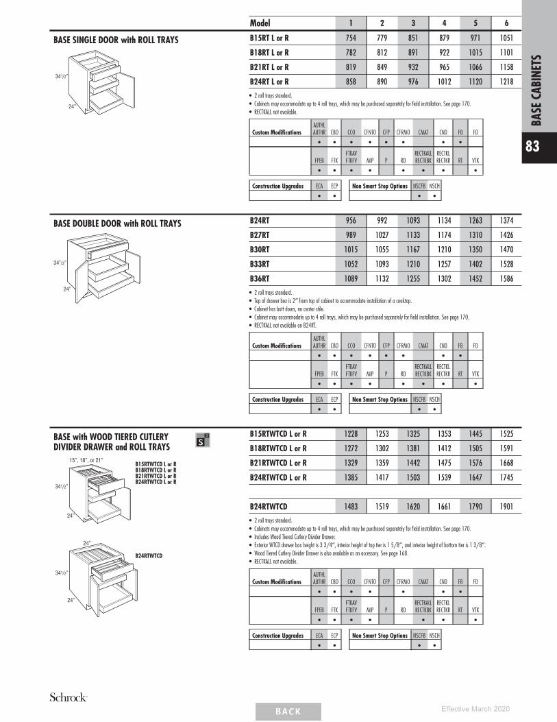
BASE SINGLE DOOR with ROLL TRAYS
24”
341/2”
Model 1 2 3 4 5 6
B15RT L or R 754 779 851 879 971 1051
B18RT L or R 782 812 891 922 1015 1101
B21RT L or R 819 849 932 965 1066 1158
B24RT L or R 858 890 976 1012 1120 1218
• 2 roll trays standard.• Cabinets may accommodate up to 4 roll trays, which may be purchased separately for field installation. See page 170.• RECTKALL not available.
Custom ModificationsAUTHLAUTHR CBO CCO CFNTO CFP CFRMO CMAT CND FB FD
• • • • • • • •
FPEB FTKFTKAVFTKFV MIP P RD
RECTKALLRECTKBK
RECTKLRECTKR RT VTK
• • • • • • • •
Construction Upgrades ECA ECP
• •
Non Smart Stop Options NSCFB NSCH
• •
BASE DOUBLE DOOR with ROLL TRAYS
341/2”
24”
B24RT 956 992 1093 1134 1263 1374
B27RT 989 1027 1133 1174 1310 1426
B30RT 1015 1055 1167 1210 1350 1470
B33RT 1052 1093 1210 1257 1402 1528
B36RT 1089 1132 1255 1302 1452 1586
• 2 roll trays standard.• Top of drawer box is 2″ from top of cabinet to accommodate installation of a cooktop.• Cabinet has butt doors, no center stile.• Cabinet may accommodate up to 4 roll trays, which may be purchased separately for field installation. See page 170.• RECTKALL not available on B24RT.
Custom ModificationsAUTHLAUTHR CBO CCO CFNTO CFP CFRMO CMAT CND FB FD
• • • • • • • •
FPEB FTKFTKAVFTKFV MIP P RD
RECTKALLRECTKBK
RECTKLRECTKR RT VTK
• • • • • • • •
Construction Upgrades ECA ECP
• •
Non Smart Stop Options NSCFB NSCH
• •
BASE with WOOD TIERED CUTLERYDIVIDER DRAWER and ROLL TRAYS
15”, 18”, or 21”
341/2”
24”
B15RTWTCD L or RB18RTWTCD L or RB21RTWTCD L or RB24RTWTCD L or R
341/2”
24”
24”
B24RTWTCD
B15RTWTCD L or R 1228 1253 1325 1353 1445 1525
B18RTWTCD L or R 1272 1302 1381 1412 1505 1591
B21RTWTCD L or R 1329 1359 1442 1475 1576 1668
B24RTWTCD L or R 1385 1417 1503 1539 1647 1745
B24RTWTCD 1483 1519 1620 1661 1790 1901
• 2 roll trays standard.• Cabinets may accommodate up to 4 roll trays, which may be purchased separately for field installation. See page 170.• Includes Wood Tiered Cutlery Divider Drawer.• Exterior WTCD drawer box height is 3 3/4″, interior height of top tier is 1 5/8″, and interior height of bottom tier is 1 3/8″.• Wood Tiered Cutlery Divider Drawer is also available as an accessory. See page 168.• RECTKALL not available.
Custom ModificationsAUTHLAUTHR CBO CCO CFNTO CFP CFRMO CMAT CND FB FD
• • • • • • •
FPEB FTKFTKAVFTKFV MIP P RD
RECTKALLRECTKBK
RECTKLRECTKR RT VTK
• • • • • • •
Construction Upgrades ECA ECP
• •
Non Smart Stop Options NSCFB NSCH
• •
BASE
CABI
NETS
83
Effective March 2020

BASE POTS & PANS PULL-OUT
341/2”
24”
24”
2” 113/4”
11”
91/2”
Shelf Depth(front to back)
21”
Model 1 2 3 4 5 6
BPPP24 1315 1351 1452 1493 1621 1733
• Full Extension slide-out shelves pull out independently.• RECTKALL not available.
Custom ModificationsAUTHLAUTHR CBO CCO CFNTO CFP CFRMO CMAT CND FB FD
• • • • • • • •
FPEB FTKFTKAVFTKFV MIP P RD
RECTKALLRECTKBK
RECTKLRECTKR RT VTK
• • • • • •
Construction Upgrades ECA ECP
• •
Non Smart Stop Options NSCFB NSCH
• •
BASE with ROLL-OUT TRAY DIVIDER
341/2”
24”
12”
73/4”
341/2”
24”
15”
103/4”
B12TDRO L or R B15TDRO L or R
B12TDRO L or R 826 852 920 949 1031 1104
B15TDRO L or R 896 921 993 1021 1113 1193
• Tray divider utilizes Smart Stop undermount guides and bumpers for door protection.• Dividers are removable.• 12″ - 3 compartments.• 15″ - 4 compartments.• RECTKALL not available.• FTKAV and FTKFV not available on B12TDRO L or R.
Custom ModificationsAUTHLAUTHR CBO CCO CFNTO CFP CFRMO CMAT CND FB FD
• • • • • • • •
FPEB FTKFTKAVFTKFV MIP P RD
RECTKALLRECTKBK
RECTKLRECTKR RT VTK
• • • • • • •
Construction Upgrades ECA ECP
• •
Non Smart Stop Options NSCFB NSCH
• •
BASE with TRAY DIVIDER
341/2”
24”
9”
341/2”
24”
12” or 15”
TD9 L or R TD12 L or RTD15 L or R
TD9 L or R 490 513 574 601 674 740
TD12 L or R 536 562 630 659 741 814
TD15 L or R 573 598 670 698 790 870
• Tray Divider is chrome.• Tray Divider is also available as an accessory for field installation. See page 169.• RECTKALL not available.• RECTKBK not available on TD9 L or R.• FTKAV and FTKFV not available on TD9 L or R and TD12 L or R.
Custom ModificationsAUTHLAUTHR CBO CCO CFNTO CFP CFRMO CMAT CND FB FD
• • • • • • • •
FPEB FTKFTKAVFTKFV MIP P RD
RECTKALLRECTKBK
RECTKLRECTKR RT VTK
• • • • • • •
Construction Upgrades ECA ECP
• •
Non Smart Stop Options NSCFB NSCH
• •
BASE
CABI
NETS
84
Effective March 2020
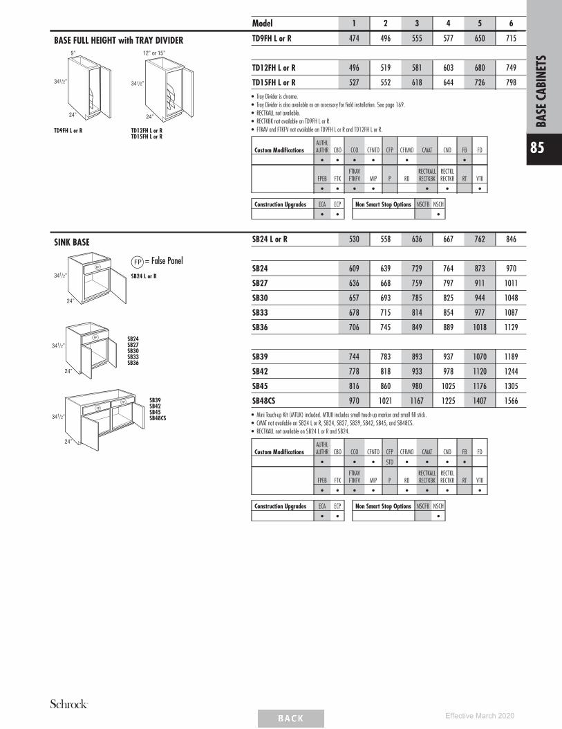
BASE FULL HEIGHT with TRAY DIVIDER
341/2”
24”
9”
341/2”
24”
12” or 15”
TD9FH L or R TD12FH L or RTD15FH L or R
Model 1 2 3 4 5 6
TD9FH L or R 474 496 555 577 650 715
TD12FH L or R 496 519 581 603 680 749
TD15FH L or R 527 552 618 644 726 798
• Tray Divider is chrome.• Tray Divider is also available as an accessory for field installation. See page 169.• RECTKALL not available.• RECTKBK not available on TD9FH L or R.• FTKAV and FTKFV not available on TD9FH L or R and TD12FH L or R.
Custom ModificationsAUTHLAUTHR CBO CCO CFNTO CFP CFRMO CMAT CND FB FD
• • • • • •
FPEB FTKFTKAVFTKFV MIP P RD
RECTKALLRECTKBK
RECTKLRECTKR RT VTK
• • • • • • •
Construction Upgrades ECA ECP
• •
Non Smart Stop Options NSCFB NSCH
•
SINK BASE
= False Panel
341/2”
24”
FP
SB24 L or R
341/2”
24”
FP SB24SB27SB30SB33SB36
FP
341/2”
24”
FP SB39SB42SB45SB48CS
SB24 L or R 530 558 636 667 762 846
SB24 609 639 729 764 873 970
SB27 636 668 759 797 911 1011
SB30 657 693 785 825 944 1048
SB33 678 715 814 854 977 1087
SB36 706 745 849 889 1018 1129
SB39 744 783 893 937 1070 1189
SB42 778 818 933 978 1120 1244
SB45 816 860 980 1025 1176 1305
SB48CS 970 1021 1167 1225 1407 1566
• Mini Touch-up Kit (MTUK) included. MTUK includes small touch-up marker and small fill stick.• CMAT not available on SB24 L or R, SB24, SB27, SB39, SB42, SB45, and SB48CS.• RECTKALL not available on SB24 L or R and SB24.
Custom ModificationsAUTHLAUTHR CBO CCO CFNTO CFP CFRMO CMAT CND FB FD
• • • STD • • • •
FPEB FTKFTKAVFTKFV MIP P RD
RECTKALLRECTKBK
RECTKLRECTKR RT VTK
• • • • • • • •
Construction Upgrades ECA ECP
• •
Non Smart Stop Options NSCFB NSCH
•
BASE
CABI
NETS
85
Effective March 2020

SINK BASE with CABMAT™
341/2”
24”
FP
Model 1 2 3 4 5 6
SB30CM 932 968 1060 1100 1219 1323
SB33CM 963 1000 1099 1139 1262 1372
SB36CM 1002 1041 1145 1185 1314 1425
• Mini Touch-up Kit (MTUK) included. MTUK includes small touch-up marker and small fill stick.• CabMat™ is designed to capture spills and is removable for cleaning.
Liquid Capacity Cabinet Size
Model Gallons Liters Width DepthSB30CM 2.0 7.6 30″ 24″
SB33CM 2.4 9.0 33″ 24″
SB36CM 2.7 10.2 36″ 24″
Custom ModificationsAUTHLAUTHR CBO CCO CFNTO CFP CFRMO CMAT CND FB FD
• • • STD • STD • •
FPEB FTKFTKAVFTKFV MIP P RD
RECTKALLRECTKBK
RECTKLRECTKR RT VTK
• • • • • • •
Construction Upgrades ECA ECP
• •
Non Smart Stop Options NSCFB NSCH
•
SINK BASE with TILT-OUT TRAYS
341/2”
24” or 27”
24”
SB24STSB27ST
341/2”
24”
SB30STSB33STSB36ST
341/2”
24”
39”, 42”, or 45”
SB39STSB42STSB45ST
SB24ST 691 725 817 857 975 1081
SB27ST 700 735 828 867 985 1090
SB30ST 710 744 837 876 995 1101
SB33ST 734 768 866 904 1026 1138
SB36ST 768 805 905 947 1075 1191
SB39ST 805 843 948 991 1127 1247
SB42ST 864 903 1011 1057 1198 1326
SB45ST 883 922 1031 1077 1217 1346
• Tilt-out trays are stain resistant, moisture resistant plastic to allow storage of sponges and other cleaning materials.• Mini Touch-up Kit (MTUK) included. MTUK includes small touch-up marker and small fill stick.• Includes two tilt-out trays on 30″-48″ wide.• Tilt-out trays are also available as an accessory for field installation. See page 169.• CMAT only available on 30″, 33″, and 36″ wide.• RECTKALL not available on SB24ST.
Custom ModificationsAUTHLAUTHR CBO CCO CFNTO CFP CFRMO CMAT CND FB FD
• • • • • •
FPEB FTKFTKAVFTKFV MIP P RD
RECTKALLRECTKBK
RECTKLRECTKR RT VTK
• • • • • • • •
Construction Upgrades ECA ECP
• •
Non Smart Stop Options NSCFB NSCH
•
BASE
CABI
NETS
86
Effective March 2020

SINK BASE with TILT-OUT TRAYS andCABMAT™
341/2”
24”
Model 1 2 3 4 5 6
SB30STCM 985 1019 1112 1151 1270 1376
SB33STCM 1019 1053 1151 1189 1311 1423
SB36STCM 1064 1101 1201 1243 1371 1487
• Mini Touch-up Kit (MTUK) included. MTUK includes small touch-up marker and small fill stick.• CabMat™ is designed to capture spills and is removable for cleaning.• Tilt-out trays are stain resistant, moisture resistant plastic to allow storage of sponges and other cleaning materials.• Includes two tilt-out trays.• Tilt-out trays are also available as on accessory for field installation. See page 169.
Liquid Capacity Cabinet Size
Model Gallons Liters Width DepthSB30STCM 2.0 7.6 30″ 24″
SB33STCM 2.4 9.0 33″ 24″
SB36STCM 2.7 10.2 36″ 24″
Custom ModificationsAUTHLAUTHR CBO CCO CFNTO CFP CFRMO CMAT CND FB FD
• • • • STD • •
FPEB FTKFTKAVFTKFV MIP P RD
RECTKALLRECTKBK
RECTKLRECTKR RT VTK
• • • • • • •
Construction Upgrades ECA ECP
• •
Non Smart Stop Options NSCFB NSCH
•
SINK BASE SUPERCABINET™ withTILT-OUT TRAYS
24”
341/2”
36”
SB36STS 1140 1177 1277 1319 1447 1563
• Quarter Round Reversible Shelf for left or right applications will be constructed from 3/4″ thick laminated furniture board.(Shelf shipped secure, can be positioned in left or right corner.)
• Mini Touch-up Kit (MTUK) included. MTUK includes small touch-up marker and small fill stick.• Both doors will have a chrome and wood two-tiered rack.• Racks on doors are 14 3/8″ wide.• Racks on doors are 3 1/4″ deep.• Includes two tilt-out trays.• Tilt-out trays are stain resistant, moisture resistant plastic to allow storage of sponges and other cleaning materials.• Tilt-out trays are also available as an accessory for field installation. See page 169.• All load bearing surfaces meet KCMA standards of 15 lbs. per square foot.
Custom ModificationsAUTHLAUTHR CBO CCO CFNTO CFP CFRMO CMAT CND FB FD
• • • • •
FPEB FTKFTKAVFTKFV MIP P RD
RECTKALLRECTKBK
RECTKLRECTKR RT VTK
• • • • • • •
Construction Upgrades ECA ECP
• •
Non Smart Stop Options NSCFB NSCH
•
SINK BASE SUPERCABINET™ withTILT-OUT TRAYS and CABMAT™
24”
341/2”
SB36STSCM 1436 1473 1573 1615 1743 1859
• Mini Touch-up Kit (MTUK) included. MTUK includes small touch-up marker and small fill stick.• CabMat™ is designed to capture spills and is removable for cleaning.• Both doors will have a chrome and wood two-tiered rack.• Racks on doors are 14 3/8″ wide.• Racks on doors are 3 1/4″ deep.• Includes two tilt-out trays.• Tilt-out trays are stain resistant, moisture resistant plastic to allow storage of sponges and other cleaning materials.• Tilt-out trays are also available as an accessory for field installation. See page 169.• All load bearing surfaces meet KCMA standards of 15 lbs. per square foot.
Liquid Capacity Cabinet Size
Model Gallons Liters Width DepthSB36STSCM 2.7 10.2 36″ 24″
Custom ModificationsAUTHLAUTHR CBO CCO CFNTO CFP CFRMO CMAT CND FB FD
• • • • STD • •
FPEB FTKFTKAVFTKFV MIP P RD
RECTKALLRECTKBK
RECTKLRECTKR RT VTK
• • • • • • •
Construction Upgrades ECA ECP
• •
Non Smart Stop Options NSCFB NSCH
•
BASE
CABI
NETS
87
Effective March 2020

ANGLED CORNER SINK BASE
FP
341/2”
24”
= False Panel
17” or 251/2”
24” 24”
36” o
r 42”
36” or 42”
299/16”
17 11/16”
271/2” or 36”
Max. Sink Widths if cut-out is 4″back
from face of front frame
Model 1 2 3 4 5 6
ACS36 L or R 466 491 559 587 672 745
ACS42† 514 540 617 647 740 822
• Edges beveled at 45°.• Mini Touch-up Kit (MTUK) included. MTUK includes small touch-up marker and small fill stick.• For sufficient dishwasher door clearance and loading/unloading space, a 15″ wide base cabinet is recommended for use between a corner
sink base and dishwasher.• On ACS36, full overlay styles use the same width doors as partial overlay styles (14 1/2″ wide) with a partial overlay hinge (38NPOHINGE) to allow
for proper door clearance with adjacent cabinets.†ACS42 has butt doors.
WallWidth Frame
MaximumSink Width
MaximumSink Depth
36″ x 36″ 17″ 25 3/4″ 27 11/32″42″ x 42″ 25 1/2″ 34 1/4″ 27 11/32″
Custom ModificationsAUTHLAUTHR CBO CCO CFNTO CFP CFRMO CMAT CND FB FD
• • • STD • • •
FPEB FTKFTKAVFTKFV MIP P RD
RECTKALLRECTKBK
RECTKLRECTKR RT VTK
• •
Construction Upgrades ECA ECP
• •
Non Smart Stop Options NSCFB NSCH
•
ANGLED CORNER SINK FRONTwithout SINK FLOOR
341/2”
FP
= False Panel
Max. Sink Widths if cut-out is 4″back
from face of front frame
ACSF36 L or R 423 448 510 533 613 678
ACSF42† 466 491 559 587 672 745
• Edges beveled at 45°.• Angled corner sink front bottom required for field installation. Order separately. See next item.• Toekick and toekick retainer shipped unattached from the face frame.• On ACSF36, full overlay styles use the same width doors as partial overlay styles (14 1/2″ wide) with a partial overlay hinge (38NPOHINGE) to
allow for proper door clearance with adjacent cabinets.†ACSF42 has butt doors.
WallWidth Frame
MaximumSink Width
MaximumSink Depth
36″ x 36″ 17″ 25 3/4″ 27 11/32″42″ x 42″ 25 1/2″ 34 1/4″ 27 11/32″
Custom ModificationsAUTHLAUTHR CBO CCO CFNTO CFP CFRMO CMAT CND FB FD
STD STD • •
FPEB FTKFTKAVFTKFV MIP P RD
RECTKALLRECTKBK
RECTKLRECTKR RT VTK
Construction Upgrades ECA ECP Non Smart Stop Options NSCFB NSCH
•
ANGLED CORNER SINK FRONTBOTTOM
231/16”
36” or 42”
ACSFB36 143 143 143 143 143 143
ACSFB42 143 143 143 143 143 143
• Designed for use with Angled Corner Sink Front.• 3/8″ thick.
MODIFICATIONS
No modifications available forthese products.
Construction Upgrades ECA ECP
•
BASE
CABI
NETS
88
Effective March 2020

COUNTRY SINK BASE
341/2”
131/2”
24”
30”, 33”, or 36”
CNTYSB30CNTYSB33CNTYSB36
341/2”
131/2”
24”
39”, 42”, or 48”
CNTYSB39CNTYSB42CNTYSB48CS
Model 1 2 3 4 5 6
CNTYSB30 853 900 1022 1072 1226 1363
CNTYSB33 882 931 1061 1113 1271 1412
CNTYSB36 918 969 1103 1156 1323 1469
CNTYSB39 967 1018 1161 1220 1391 1546
CNTYSB42 1011 1067 1211 1269 1454 1617
CNTYSB48CS 1268 1336 1526 1599 1836 2043
• 13 1/2″ panel can be trimmed up to 12″.• Mini Touch-up Kit (MTUK) included. MTUK includes small touch-up marker and small fill stick.• For apron front sinks requiring a cut-out height of 6 1/2″ or less, see Base Drop-in Range Cabinets on page 100.• Refer to manufacturer’s recommendations for additional support required for apron front sinks.• CMAT not available on CNTYSB39, CNTYSB42, and CNTYSB48CS.
Custom ModificationsAUTHLAUTHR CBO CCO CFNTO CFP CFRMO CMAT CND FB FD
• • • • • •
FPEB FTKFTKAVFTKFV MIP P RD
RECTKALLRECTKBK
RECTKLRECTKR RT VTK
• • • • • • • •
Construction Upgrades ECA ECP
• •
Non Smart Stop Options NSCFB NSCH
•
COUNTRY SINK BASE with CABMAT™
341/2”
131/2”
24”
CNTYSB30CM 1128 1175 1297 1347 1501 1638
CNTYSB33CM 1167 1216 1346 1398 1556 1697
CNTYSB36CM 1214 1265 1399 1452 1619 1765
• Mini Touch-up Kit (MTUK) included. MTUK includes small touch-up marker and small fill stick.• CabMat™ is designed to capture spills and is removable for cleaning.• 13 1/2″ panel can be trimmed to 12″.• For apron front sinks requiring a cut-out height of 6 1/2″ or less, see Base Drop-in Range Cabinets on page 100.• Refer to manufacturer’s recommendations for additional support required for apron front sinks.
Liquid Capacity Cabinet Size
Model Gallons Liters Width DepthCNTYSB30CM 2.0 7.6 30″ 24″
CNTYSB33CM 2.4 9.0 33″ 24″
CNTYSB36CM 2.7 10.2 36″ 24″
Custom ModificationsAUTHLAUTHR CBO CCO CFNTO CFP CFRMO CMAT CND FB FD
• • • • STD •
FPEB FTKFTKAVFTKFV MIP P RD
RECTKALLRECTKBK
RECTKLRECTKR RT VTK
• • • • • • •
Construction Upgrades ECA ECP
• •
Non Smart Stop Options NSCFB NSCH
•
BASE
CABI
NETS
89
Effective March 2020

Sink Base Corner Cabinets• SBCs use the wall space the nomenclature
implies.• Remember to use 3″ filler on adjoining cabinets.• The adjoining run of cabinets will cover the void.• The L or R in the cabinet nomenclature indicates
the location of the void to ensure clearance; it isnot recommended to place SBC cabinets next to27″ deep appliances.
Front View Top View
C
D
E
AdjacentCabinet
Clearance Sink BaseCorner Cabinet
CA
Max. SpaceMin. Space
Wall
Wall
F
Cabinet
Cabi
net
3” Filler B
D
E
Void
Model
AMin.
Space
BMax.Pull*
CMax.Space
DCabinetOpening
E*Full Overlay**
At Min. At Max.
E*Partial Overlay
At Min. At Max.
FActual
CabinetSBC51 51″ 4 1/2″ 55 1/2″ 21″ 3 1/4″ 7 3/4″ 4″ 8 1/2″ 48″SBC54 54″ 4 1/2″ 58 1/2″ 24″ 3 1/4″ 7 3/4″ 4″ 8 1/2″ 51″SBC57 57″ 4 1/2″ 61 1/2″ 27″ 3 1/4″ 7 3/4″ 4″ 8 1/2″ 54″SBC60 60″ 4 1/2″ 64 1/2″ 30″ 3 1/4″ 7 3/4″ 4″ 8 1/2″ 57″SBC63 63″ 4 1/2″ 67 1/2″ 33″ 3 1/4″ 7 3/4″ 4″ 8 1/2″ 60″*Minimum/maximum space between inside edge of door and face of filler/adjoining cabinet. If cabinet is pulled to maximum stated dimension, filler will need to be cleated forproper attachment.
**Full overlay styles must be pulled on additional 1 1/2" to ensure proper drawer/pull clearance. 1 1/2" pull is not included in minimum and maximum list.
SINK BASE CORNER
24”48”
51”
341/2”
FP
24”
341/2”
51”, 54”, 57”, or 60”
54”, 57”, 60”, or 63”
FP
Model 1 2 3 4 5 6
SBC51 L or R 958 997 1101 1142 1262 1368
SBC54 L or R 1084 1127 1245 1291 1428 1548
SBC57 L or R 1092 1136 1255 1301 1439 1560
SBC60 L or R 1101 1145 1265 1312 1451 1572
SBC63 L or R 1109 1154 1275 1322 1462 1584
• Not recommended for use next to an appliance deeper than standard cabinet depth.• Includes one 3″ filler, shipped unattached.• L or R indicates void. L (left) void shown.• Face Frame and Door on End modification not available on the void side of the cabinet.• On void side, do not install next to an appliance deeper than standard cabinet depth due to clearance needed for the door and drawer.• Mini Touch-up Kit (MTUK) included. MTUK includes small touch-up marker and small fill stick.
Sink Base Frame Sink Base Cabinet # ofFull OverlayDoor Style
Partial OverlayDoor Size
Opening Width Equivalent Width Doors Width Height Width HeightSBC51 21″ 24″ 1 23 1/2″ 23″ 22″ 21 1/2″SBC54 24″ 27″ 2 13 3/16″ 23″ 12 7/16″ 21 1/2″SBC57 27″ 30″ 2 14 11/16″ 23″ 13 15/16″ 21 1/2″SBC60 30″ 33″ 2 16 3/16″ 23″ 15 7/16″ 21 1/2″SBC63 33″ 36″ 2 17 11/16″ 23″ 16 15/16″ 21 1/2″
Custom ModificationsAUTHLAUTHR CBO CCO CFNTO CFP CFRMO CMAT CND FB FD
• • • STD • • •
FPEB FTKFTKAVFTKFV MIP P RD
RECTKALLRECTKBK
RECTKLRECTKR RT VTK
• • • • • • •
Construction Upgrades ECA ECP
• •
Non Smart Stop Options NSCFB NSCH
•
BASE
CABI
NETS
90
Effective March 2020

Base Corner Cabinets• BCs use the wall space the nomenclature implies.• Remember to use 3″ filler on adjoining cabinets.• The adjoining run of cabinets will cover the void.• The L or R in the cabinet nomenclature indicates
the location of the void to ensure clearance; it isnot recommended to place BC cabinets next to27″ deep appliances.
Front View Top View
C
D
E
AdjacentCabinet
Clearance Base SquareCorner Cabinet
CA
Max. SpaceMin. Space
Wall
Wall
F
Cabinet
Cabi
net
3” Filler B
D
E
Void
Model
AMin.
Space
BMax.Pull*
CMax.Space
DCabinetOpening
E*Full Overlay**
At Min. At Max.
E*Partial Overlay
At Min. At Max.
FActual
Cabinet
Face FrameOpeningWidth
Full OverlayDoorWidth
Partial OverlayDoorWidth
BC36 36″ 6″ 42″ 7 1/2″ 1 3/4″ 7 3/4″ 2 1/2″ 8 1/2″ 27″ 7 1/2″ 10″ 8 1/2″BC39 39″ 4 1/2″ 43 1/2″ 9″ 3 1/4″ 7 3/4″ 4″ 8 1/2″ 30″ 9″ 11 1/2″ 10″BC42 42″ 6″ 48″ 13 1/2″ 1 3/4″ 7 3/4″ 2 1/2″ 8 1/2″ 39″ 13 1/2″ 16″ 14 1/2″BC45 45″ 4 1/2″ 49 1/2″ 15″ 3 1/4″ 7 3/4″ 4″ 8 1/2″ 42″ 15″ 17 1/2″ 16″BC48 48″ 3″ 51″ 16 1/2″ 4 1/4″ 7 3/4″ 5 1/2″ 8 1/2″ 45″ 16 1/2″ 19″ 17 1/2″*Minimum/maximum space between inside edge of door and face of filler/adjoining cabinet. If cabinet is pulled to maximum stated dimension, filler will need to be cleated for proper attachment.**Full overlay styles must be pulled on additional 1 1/2" to ensure proper drawer/pull clearance. 1 1/2" pull is not included in minimum and maximum list.
BASE CORNER
341/2”
24”
BC36 - 27″ wideBC39 - 30″ wideBC42 - 39″ wideBC45 - 42″ wideBC48 - 45″ wide
Model 1 2 3 4 5 6
BC36 L or R 598 621 686 711 788 853
BC39 L or R 642 668 737 765 846 916
BC42 L or R 689 716 791 819 907 983
BC45 L or R 734 763 842 873 966 1047
BC48 L or R 780 812 896 930 1028 1114
• Includes one 3″ filler, shipped unattached.• L or R indicates void. L (left) void shown.• Adjustable 15″ deep shelves.• On void side, do not install next to an appliance deeper than standard cabinet depth due to clearance needed for the door and drawer.
Custom ModificationsAUTHLAUTHR CBO CCO CFNTO CFP CFRMO CMAT CND FB FD
• • • • • • • • •
FPEB FTKFTKAVFTKFV MIP P RD
RECTKALLRECTKBK
RECTKLRECTKR RT VTK
• • • • • • •
Construction Upgrades ECA ECP
• •
Non Smart Stop Options NSCFB NSCH
• •
BASE LAZY SUSAN CORNER with FULLHEIGHT DOOR and LAZY SUSAN (WithCenter Hinge Door)
341/2”
24”
36”
12”
24”
36”
24”
12”
43/4”
43/4”
91/8”
91/8”
123 /4”
BLS36 L or R 1009 1064 1210 1267 1451 1613
• BLS36 L or R wall width is 36″ x 36″.• Cabinet is drum-shaped; adjoining cabinets create sides.• BLS white plastic shelves are 28″ diameter with a chrome pole.• See Panels & Skins section for BLSBEPLAM if used at end of cabinet run.• If ordered with ECA, construction and price will not change.• Drum diameter is 31 1/8″ and composed of 1/8″ thick hardboard.• Decorative hardware screws must be countersunk to prevent scratching of adjacent cabinets and face frame of BLS.• Not recommended for use next to an appliance deeper than standard cabinet depth.
Custom ModificationsAUTHLAUTHR CBO CCO CFNTO CFP CFRMO CMAT CND FB FD
• •
FPEB FTKFTKAVFTKFV MIP P RD
RECTKALLRECTKBK
RECTKLRECTKR RT VTK
Construction Upgrades ECA ECP Non Smart Stop Options NSCFB NSCH
BASE
CABI
NETS
91
Effective March 2020
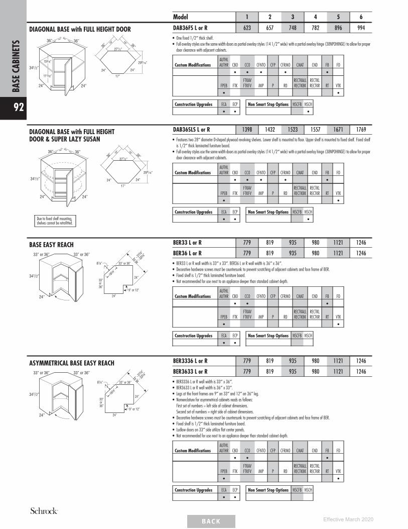
DIAGONAL BASE with FULL HEIGHT DOOR
24”
36”
341/2”
24”
36”
159/16”
1113/32” 17”
24” 24”
36”
271/2”
19”
36”
19”
299/16”
Model 1 2 3 4 5 6
DAB36FS L or R 623 657 748 782 896 994
• One fixed 1/2″ thick shelf.• Full overlay styles use the same width doors as partial overlay styles (14 1/2″ wide) with a partial overlay hinge (38NPOHINGE) to allow for proper
door clearance with adjacent cabinets.
Custom ModificationsAUTHLAUTHR CBO CCO CFNTO CFP CFRMO CMAT CND FB FD
• • • • •
FPEB FTKFTKAVFTKFV MIP P RD
RECTKALLRECTKBK
RECTKLRECTKR RT VTK
• •
Construction Upgrades ECA ECP
• •
Non Smart Stop Options NSCFB NSCH
•
DIAGONAL BASE with FULL HEIGHTDOOR & SUPER LAZY SUSAN
24”
36”
341/2”
24”
36”
17”
24” 24”
36”
271/2”
19”
36”
19”
299/16”
Due to fixed shelf mounting,shelves cannot be retrofitted.
DAB36SLS L or R 1398 1432 1523 1557 1671 1769
• Features two 28″ diameter D-shaped plywood revolving shelves. Lower shelf is mounted to floor. Upper shelf is mounted to fixed shelf. Fixed shelfis 1/2″ thick laminated furniture board.
• Full overlay styles use the same width doors as partial overlay styles (14 1/2″ wide) with a partial overlay hinge (38NPOHINGE) to allow for properdoor clearance with adjacent cabinets.
Custom ModificationsAUTHLAUTHR CBO CCO CFNTO CFP CFRMO CMAT CND FB FD
• • • • •
FPEB FTKFTKAVFTKFV MIP P RD
RECTKALLRECTKBK
RECTKLRECTKR RT VTK
• •
Construction Upgrades ECA ECP
• •
Non Smart Stop Options NSCFB NSCH
•
BASE EASY REACH
341/2”
24”
33” or 36” 33” or 36”
33” or 36”
33” or36”
24”
24”
87/8”
183 /8”
9” or 12”
36” - 3
35 /8”
33” - 3
15 /8”
BER33 L or R 779 819 935 980 1121 1246
BER36 L or R 779 819 935 980 1121 1246
• BER33 L or R wall width is 33″ x 33″. BER36 L or R wall width is 36″ x 36″.• Decorative hardware screws must be countersunk to prevent scratching of adjacent cabinets and face frame of BER.• Fixed shelf is 1/2″ thick laminated furniture board.• Not recommended for use next to an appliance deeper than standard cabinet depth.
Custom ModificationsAUTHLAUTHR CBO CCO CFNTO CFP CFRMO CMAT CND FB FD
• • •
FPEB FTKFTKAVFTKFV MIP P RD
RECTKALLRECTKBK
RECTKLRECTKR RT VTK
• •
Construction Upgrades ECA ECP
• •
Non Smart Stop Options NSCFB NSCH
ASYMMETRICAL BASE EASY REACH
341/2”
24”
33” or 36” 33” or 36”
33” or 36”
33” or36”
24”
24”
87/8”
183 /8”
9” or 12”
36” - 3
35 /8”
33” - 3
15 /8”
BER3336 L or R 779 819 935 980 1121 1246
BER3633 L or R 779 819 935 980 1121 1246
• BER3336 L or R wall width is 33″ x 36″.• BER3633 L or R wall width is 36″ x 33″.• Legs at the front frames are 9″ on 33″ and 12″ on 36″ leg.• Nomenclature for asymmetrical cabinets reads as follows:
First set of numbers = left side of cabinet dimensions.Second set of numbers = right side of cabinet dimensions.
• Decorative hardware screws must be countersunk to prevent scratching of adjacent cabinets and face frame of BER.• Fixed shelf is 1/2″ thick laminated furniture board.• Ludlow doors on 33″ side utilize flat center panels.• Not recommended for use next to an appliance deeper than standard cabinet depth.
Custom ModificationsAUTHLAUTHR CBO CCO CFNTO CFP CFRMO CMAT CND FB FD
• • •
FPEB FTKFTKAVFTKFV MIP P RD
RECTKALLRECTKBK
RECTKLRECTKR RT VTK
• •
Construction Upgrades ECA ECP
• •
Non Smart Stop Options NSCFB NSCH
BASE
CABI
NETS
92
Effective March 2020

SUPER LAZY SUSAN
341/2”
24”
33” or 36” 33” or 36”
9” or 12”
33” or 36”
33”or
36”
24”
24”
87/8”
183 /8”
33”-
315 /8”
36”-
335 /8”
Due to fixed shelf mounting,shelves cannot be retrofitted.
Model 1 2 3 4 5 6
SLS33 L or R 1874 1914 2030 2074 2216 2340
SLS36 L or R 1874 1914 2030 2074 2216 2340
• SLS33 L or R wall width is 33″ x 33″.• SLS36 L or R wall width is 36″ x 36″.• SLS33 - Susans are 28″ diameter.• SLS36 - Susans are 32″ diameter.• Features two plywood revolving shelves. Lower shelf is mounted to floor. Upper shelf is mounted to fixed shelf. Fixed shelf is 1/2″ thick laminated
furniture board.• Decorative hardware screws must be countersunk to prevent scratching adjacent cabinets and face frame of SLS.• Ludlow doors on SLS33 utilize flat center panels.• Not recommended for use next to an appliance deeper than standard cabinet depth.
Custom ModificationsAUTHLAUTHR CBO CCO CFNTO CFP CFRMO CMAT CND FB FD
• • •
FPEB FTKFTKAVFTKFV MIP P RD
RECTKALLRECTKBK
RECTKLRECTKR RT VTK
• •
Construction Upgrades ECA ECP
• •
Non Smart Stop Options NSCFB NSCH
SOLID-WOOD SUPER LAZY SUSAN
341/2”
24”
33” or 36” 33” or 36”
9” or 12”
33” or 36”
33”or
36”
24”
24”
87/8”
183 /8”
33”-
315 /8”
36”-
335 /8”
Due to fixed shelf mounting,shelves cannot be retrofitted.
SLSW33 L or R 2342 2392 2537 2591 2769 2924
SLSW36 L or R 2342 2392 2537 2591 2769 2924
• SLSW33 L or R wall width is 33″ x 33″.• SLSW36 L or R wall width is 36″ x 36″.• SLSW33 L or R - Susans are 28″ diameter.• SLSW36 L or R - Susans are 32″ diameter.• Features two hardwood revolving shelves. Lower shelf is mounted to floor. Upper shelf is mounted to fixed shelf. Fixed shelf is 1/2″ thick laminated
furniture board.• Decorative hardware screws must be countersunk to prevent scratching adjacent cabinets and face frame of SLS.• Not recommended for use next to an appliance deeper than standard cabinet depth.
Custom ModificationsAUTHLAUTHR CBO CCO CFNTO CFP CFRMO CMAT CND FB FD
• • • •
FPEB FTKFTKAVFTKFV MIP P RD
RECTKALLRECTKBK
RECTKLRECTKR RT VTK
•
Construction Upgrades ECA ECP
• •
Non Smart Stop Options NSCFB NSCH
ASYMMETRICAL SUPER LAZY SUSAN
341/2”
24”
33” or 36” 33” or 36”
9” or 12”
33” or 36”
33”or
36”
24”
24”
87/8”
183 /8”
33”-
315 /8”
36”-
335 /8”
Due to fixed shelf mounting,shelves cannot be retrofitted.
SLS3336 L or R 1874 1914 2030 2074 2216 2340
SLS3633 L or R 1874 1914 2030 2074 2216 2340
• SLS3336 L or R wall width is 33″ x 36″.• SLS3633 L or R wall width is 36″ x 33″.• All Asymmetrical Super Susan shelves are 28″ diameter.• Features two plywood revolving shelves. Lower shelf is mounted to floor. Upper shelf is mounted to fixed shelf. Fixed shelf is 1/2″ thick laminated
furniture board.• Nomenclature for asymmetrical cabinets reads as follows:
First set of numbers = left side of cabinet dimensions.Second set of numbers = right side of cabinet dimensions.
• Decorative hardware screws must be countersunk to prevent scratching adjacent cabinets and face frame of SLS.• Ludlow doors on 33″ side utilize flat center panels.• Not recommended for use next to an appliance deeper than standard cabinet depth.
Custom ModificationsAUTHLAUTHR CBO CCO CFNTO CFP CFRMO CMAT CND FB FD
• • •
FPEB FTKFTKAVFTKFV MIP P RD
RECTKALLRECTKBK
RECTKLRECTKR RT VTK
• •
Construction Upgrades ECA ECP
• •
Non Smart Stop Options NSCFB NSCH
BASE
CABI
NETS
93
Effective March 2020

ASYMMETRICAL SOLID-WOOD SUPERLAZY SUSAN
341/2”
24”
33” or 36” 33” or 36”
9” or 12”
33” or 36”
33”or
36”
24”
24”
87/8”
183 /8”
33”-
315 /8”
36”-
335 /8”
Due to fixed shelf mounting,shelves cannot be retrofitted.
Model 1 2 3 4 5 6
SLSW3336 L or R 2342 2392 2537 2591 2769 2924
SLSW3633 L or R 2342 2392 2537 2591 2769 2924
• SLSW3336 L or R wall width is 33″ x 36″.• SLSW3633 L or R wall widths is 36″ x 33″.• All Asymmetrical Super Susan shelves are 28″ diameter.• Features two hardwood revolving shelves. Lower shelf is mounted to floor. Upper shelf is mounted to fixed shelf. Fixed shelf is 1/2″ thick laminated
furniture board.• Nomenclature for asymmetrical cabinets reads as follows:
First set of numbers = left side of cabinet dimensions.Second set of numbers = right side of cabinet dimensions.
• Decorative hardware screws must be countersunk to prevent scratching adjacent cabinets and face frame of SLS.• Not recommended for use next to an appliance deeper than standard cabinet depth.
Custom ModificationsAUTHLAUTHR CBO CCO CFNTO CFP CFRMO CMAT CND FB FD
• • •
FPEB FTKFTKAVFTKFV MIP P RD
RECTKALLRECTKBK
RECTKLRECTKR RT VTK
• •
Construction Upgrades ECA ECP
• •
Non Smart Stop Options NSCFB NSCH
BASE TRANSITION CABINET
24”12”
12”
17”(Diagonal Front Width)
341/2”LR RL
Hinging Options 90°
24”
12”
12”
135°
135°
90°
225°
45°
Top View
BTC12RL 511 539 614 642 735 814
BTC12LR 511 539 614 642 735 814
• One adjustable shelf.• Cabinets constructed with top.• Door hinged on shallow depth side.• Reduced Depth to 18″ available.• Full overlay styles use the same width doors as partial overlay styles (14 1/2″ wide) with a partial overlay hinge (38NPOHINGE) to allow for proper
door clearance with adjacent cabinets.
Custom ModificationsAUTHLAUTHR CBO CCO CFNTO CFP CFRMO CMAT CND FB FD
• • • • • •
FPEB FTKFTKAVFTKFV MIP P RD
RECTKALLRECTKBK
RECTKLRECTKR RT VTK
• • • • • •
Construction Upgrades ECA ECP
• •
Non Smart Stop Options NSCFB NSCH
•
BASE END CABINET
341/2”
24” 24”24”
24”
24”
183/8”
183 /8
”
135˚
671/2˚
671/2˚
Top View
BEC24 794 834 952 996 1152 1266
• Wall width is 24″ x 24″.• 24″ W x 24″ D x 34 1/2″ H.• 24″ from outside corner point to frame face.• Cabinets constructed with top.• One adjustable shelf.• Cabinet may be installed against either end of a run.
Custom ModificationsAUTHLAUTHR CBO CCO CFNTO CFP CFRMO CMAT CND FB FD
• •
FPEB FTKFTKAVFTKFV MIP P RD
RECTKALLRECTKBK
RECTKLRECTKR RT VTK
• • •
Construction Upgrades ECA ECP
•
Non Smart Stop Options NSCFB NSCH
•
BASE
CABI
NETS
94
Effective March 2020

TWO DRAWER BASE
341/2”
24”
18”, 21”, 24”, 30”, or 36”
Model 1 2 3 4 5 6
2DB18 1104 1132 1211 1241 1328 1402
2DB21 1124 1153 1233 1263 1352 1427
2DB24 1102 1130 1209 1238 1325 1399
2DB30 1703 1749 1870 1914 2049 2163
2DB36 1758 1805 1929 1977 2116 2233
• Exterior drawer box height is 10″.• RECTKALL not available on 2DB18, 2DB21, and 2DB24.
Custom ModificationsAUTHLAUTHR CBO CCO CFNTO CFP CFRMO CMAT CND FB FD
• • • • •
FPEB FTKFTKAVFTKFV MIP P RD
RECTKALLRECTKBK
RECTKLRECTKR RT VTK
• • • • • • •
Construction Upgrades ECA ECP
• •
Non Smart Stop Options NSCFB NSCH
TWO DRAWER BASE with ROLL TRAY
341/2”
24”
24”, 30”, or 36”
2DB24RT 1188 1220 1304 1335 1430 1508
2DB30RT 1805 1853 1980 2029 2171 2292
2DB36RT 1853 1901 2032 2083 2229 2351
• Includes a roll tray inside top drawer.• Exterior height for bottom drawer box is 6 3/8″.• RECTKALL not available on 2DB24RT.
Custom ModificationsAUTHLAUTHR CBO CCO CFNTO CFP CFRMO CMAT CND FB FD
• • • • • •
FPEB FTKFTKAVFTKFV MIP P RD
RECTKALLRECTKBK
RECTKLRECTKR RT VTK
• • • • • • •
Construction Upgrades ECA ECP
• •
Non Smart Stop Options NSCFB NSCH
TWO DRAWER BASE, DROP-IN RANGE
24”
36”
8” panel can betrimmed to 61/2”
341/2”8”
2DB36DR 2085 2140 2286 2343 2508 2647
• Exterior height of drawer boxes is 6 3/8″.
Custom ModificationsAUTHLAUTHR CBO CCO CFNTO CFP CFRMO CMAT CND FB FD
• • • • • •
FPEB FTKFTKAVFTKFV MIP P RD
RECTKALLRECTKBK
RECTKLRECTKR RT VTK
• • • • • • •
Construction Upgrades ECA ECP
• •
Non Smart Stop Options NSCFB NSCH
BASE
CABI
NETS
95
Effective March 2020

THREE DRAWER BASE
341/2”
24”
3DB123DB153DB183DB21
24”
341/2”
24”, 27”, 30”, 33”, or 36”
3DB243DB273DB303DB333DB36
Model 1 2 3 4 5 6
3DB12 641 661 716 737 800 853
3DB15 690 711 771 794 861 917
3DB18 738 762 826 850 922 983
3DB21 794 818 886 912 990 1055
3DB24 846 873 945 973 1055 1126
3DB27 1093 1126 1211 1245 1340 1422
3DB30 1352 1391 1497 1537 1656 1756
3DB33 1398 1439 1548 1590 1713 1817
3DB36 1441 1482 1596 1638 1765 1874
• Exterior height of bottom 2 drawer boxes is 6 3/8″.• NSCFB not available on 3DB30, 3DB33, and 3DB36.• RECTKALL not available on 3DB12, 3DB15, 3DB18, 3DB21, and 3DB24.
Custom ModificationsAUTHLAUTHR CBO CCO CFNTO CFP CFRMO CMAT CND FB FD
• • • • • • •
Custom Modifications FPEB FTKFTKAVFTKFV MIP P RD
RECTKALLRECTKBK
RECTKLRECTKR RT VTK
• • • • • • •
Construction Upgrades ECA ECP
• •
Non Smart Stop Options NSCFB NSCH
•
THREE DRAWER BASE with WOODTIERED CUTLERY DIVIDER DRAWER
15”, 18”, 21”, or 24”
341/2”
24”
3DB15WTCD 1164 1185 1245 1268 1335 1391
3DB18WTCD 1228 1252 1316 1340 1412 1473
3DB21WTCD 1304 1328 1396 1422 1500 1565
3DB24WTCD 1373 1400 1472 1500 1582 1653
• Includes Wood Tiered Cutlery Divider Drawer in top drawer.• Exterior height for lower drawer boxes is 6 3/8″.• Exterior WTCD drawer box height is 3 3/4″, interior height of top tier is 1 5/8″, and interior height of bottom tier is 1 3/8″.• Wood Tiered Cutlery Divider Drawer is also available as an accessory. See page 168.• RECTKALL not available.
Custom ModificationsAUTHLAUTHR CBO CCO CFNTO CFP CFRMO CMAT CND FB FD
• • • • • •
FPEB FTKFTKAVFTKFV MIP P RD
RECTKALLRECTKBK
RECTKLRECTKR RT VTK
• • • • • •
Construction Upgrades ECA ECP
• •
Non Smart Stop Options NSCFB NSCH
THREE DRAWER BASE with DEEPDRAWER
24”
341/2”
24”, 30”, 33”, or 36”
3DBDD24 1442 1480 1581 1620 1734 1830
3DBDD30 1710 1755 1876 1922 2057 2170
3DBDD33 1931 1982 2118 2169 2322 2451
3DBDD36 2084 2138 2286 2342 2507 2646
• Exterior height of bottom drawer box is 10″.• RECTKALL not available on 3DBDD24.
Custom ModificationsAUTHLAUTHR CBO CCO CFNTO CFP CFRMO CMAT CND FB FD
• • • • • •
FPEB FTKFTKAVFTKFV MIP P RD
RECTKALLRECTKBK
RECTKLRECTKR RT VTK
• • • • • • •
Construction Upgrades ECA ECP
• •
Non Smart Stop Options NSCFB NSCH
BASE
CABI
NETS
96
Effective March 2020

FOUR DRAWER BASE
341/2”
24”
Model 1 2 3 4 5 6
4DB12 682 703 762 784 851 908
4DB15 736 760 823 847 919 980
4DB18 793 817 885 912 989 1054
4DB21 845 872 944 971 1054 1124
4DB24 908 937 1014 1045 1133 1208
• RECTKALL not available.• FTKAV and FTKFV not available on 4DB12.
Custom ModificationsAUTHLAUTHR CBO CCO CFNTO CFP CFRMO CMAT CND FB FD
• • • • • • •
FPEB FTKFTKAVFTKFV MIP P RD
RECTKALLRECTKBK
RECTKLRECTKR RT VTK
• • • • • • •
Construction Upgrades ECA ECP
• •
Non Smart Stop Options NSCFB NSCH
•
FOUR DRAWER BASE with WOODTIERED CUTLERY DIVIDER DRAWER
15”, 18”, 21”, or 24”
341/2”
24”
4DB15WTCD 1210 1234 1297 1321 1393 1454
4DB18WTCD 1283 1307 1375 1402 1479 1544
4DB21WTCD 1355 1382 1454 1481 1564 1634
4DB24WTCD 1435 1464 1541 1572 1660 1735
• Includes Wood Tiered Cutlery Divider Drawer in top drawer.• Exterior WTCD drawer box height is 3 3/4″, interior height of top tier is 1 5/8″, and interior height of bottom tier is 1 3/8″.• Wood Tiered Cutlery Divider Drawer is also available as an accessory. See page 168.• RECTKALL not available.
Custom ModificationsAUTHLAUTHR CBO CCO CFNTO CFP CFRMO CMAT CND FB FD
• • • • • •
FPEB FTKFTKAVFTKFV MIP P RD
RECTKALLRECTKBK
RECTKLRECTKR RT VTK
• • • • • •
Construction Upgrades ECA ECP
• •
Non Smart Stop Options NSCFB NSCH
BASE WASTEBASKET
341/2”
24”
15”
BWB15
24”
341/2”
18” or 21”
BWB18BWB21
BWB15 944 970 1041 1069 1161 1242
BWB18 972 1002 1081 1112 1205 1291
BWB21 1010 1039 1122 1155 1256 1348
• Pull-out features undermount Smart Stop guides.• BWB15 includes one 35 quart gray wastebasket and a trash bag storage area.• BWB18 and BWB21 include two 35 quart gray wastebaskets.• RECTKALL not available.
Custom ModificationsAUTHLAUTHR CBO CCO CFNTO CFP CFRMO CMAT CND FB FD
• • • • • •
FPEB FTKFTKAVFTKFV MIP P RD
RECTKALLRECTKBK
RECTKLRECTKR RT VTK
• • • • • •
Construction Upgrades ECA ECP
• •
Non Smart Stop Options NSCFB NSCH
•
BASE
CABI
NETS
97
Effective March 2020

BASE WASTEBASKET FULL HEIGHT
341/2”
24”
15”
BWB15FH
24”
18”
341/2”
BWB18FH2
341/2”
24”
21”
BWB21FH
Model 1 2 3 4 5 6
BWB15FH 898 922 989 1015 1096 1168
BWB18FH2 925 952 1024 1051 1138 1216
BWB21FH 958 986 1061 1091 1185 1266
• Pull-out features undermount Smart Stop guides.• BWB15FH includes one 50 quart gray wastebasket and a trash bag storage area.• BWB18FH2 includes two 35 quart gray wastebaskets.• BWB21FH includes two 50 quart gray wastebaskets.• RECTKALL not available.
Custom ModificationsAUTHLAUTHR CBO CCO CFNTO CFP CFRMO CMAT CND FB FD
• • • •
FPEB FTKFTKAVFTKFV MIP P RD
RECTKALLRECTKBK
RECTKLRECTKR RT VTK
• • • • • •
Construction Upgrades ECA ECP
• •
Non Smart Stop Options NSCFB NSCH
BASE WINE CUBBY, 24″ DEEP6”
341/2”
51/8”24”
41/2”Opening Width
Opening Height
BWC6 846 846 846 846 846 846
• Vertical application only.• Matching Interior Plywood (MIP) standard.• Frameless drilled and doweled construction.• Veneer on 3/4″ furniture board core.• Reduced Depth only available in 3″ increments down to 12″.
Custom ModificationsAUTHLAUTHR CBO CCO CFNTO CFP CFRMO CMAT CND FB FD
STD
FPEB FTKFTKAVFTKFV MIP P RD
RECTKALLRECTKBK
RECTKLRECTKR RT VTK
STD • •
Construction Upgrades ECA ECP Non Smart Stop Options NSCFB NSCH
BASE PANTRY PULL-OUT
24”
341/2”
9” or 12”
InteriorWidths4” or 7”
Pull-outInteriorDepth211/4”
BPP9 1184 1234 1376 1434 1608 1761
BPP12 1269 1326 1481 1543 1732 1900
• All styles feature a natural finish Smart Stop wood pull-out with adjustable shelves and chrome rail sides. The adjustable rear wall of the pull-outprevents items from falling behind the unit.
• RECTKALL not available.• RECTKBK not available on BPP9.
Custom ModificationsAUTHLAUTHR CBO CCO CFNTO CFP CFRMO CMAT CND FB FD
• • • • •
FPEB FTKFTKAVFTKFV MIP P RD
RECTKALLRECTKBK
RECTKLRECTKR RT VTK
• • • • •
Construction Upgrades ECA ECP
• •
Non Smart Stop Options NSCFB NSCH
BASE
CABI
NETS
98
Effective March 2020

BASE UTENSIL PANTRY PULL-OUT
24”
341/2”
9” or 12”
InteriorWidths4” or 7”
Pull-outInteriorDepth211/4”
Model 1 2 3 4 5 6
BUPP9 1629 1679 1821 1879 2053 2207
BUPP12 1715 1772 1926 1989 2178 2345
• All styles feature a natural finish Smart Stop wood pull-out with two adjustable shelves (including canister shelf) and one fixed shelf with chrome railsides. Top adjustable shelf features three stainless steel canisters for utensils. The adjustable rear wall of the pull-out prevents items from falling behindthe unit.
• BUPP9 canisters are 5.85″ tall and have an inside diameter of 4.3″.• BUPP12 canisters are 6.7″ tall and have an inside diameter of 5″.• RECTKALL not available.• RECTKBK not available on BUPP9.
Custom ModificationsAUTHLAUTHR CBO CCO CFNTO CFP CFRMO CMAT CND FB FD
• • • • •
FPEB FTKFTKAVFTKFV MIP P RD
RECTKALLRECTKBK
RECTKLRECTKR RT VTK
• • • • •
Construction Upgrades ECA ECP
• •
Non Smart Stop Options NSCFB NSCH
BASE UTENSIL PANTRY PULL-OUTwith KNIFE BLOCK
341/2”
24”
12”
BUPPKB12
341/2”
24”
15”
BUPPKB15
BUPPKB12 2287 2344 2499 2561 2750 2918
BUPPKB15 2659 2716 2871 2933 3122 3290
• Full extension, Smart Stop wood pull-out with natural finish and one fixed shelf.• BUPPKB12 features an adjustable shelf with two knife blocks, one stainless steel canister and one fixed shelf with chrome rails. Canister is 6.7″ tall
and has an inside diameter of 5″.• BUPPKB15 features an adjustable shelf with two knife blocks, four stainless steel canisters and one fixed shelf with chrome rails. Two canisters are
5.85″ tall and have an inside diameter of 4.3″, and the other two are 6.7″ tall with an inside diameter of 5″.• Knife block features movable flex rods that adjust to hold a multitude of knives.• Includes adjustable rear wall for extra strength and stability.• Adjustable shelf is easily reversible for placement of knife blocks in the front or rear.• RECTKALL not available.• FTKAV and FTKFV not available on BUPPKB12.
Custom ModificationsAUTHLAUTHR CBO CCO CFNTO CFP CFRMO CMAT CND FB FD
• • • • •
FPEB FTKFTKAVFTKFV MIP P RD
RECTKALLRECTKBK
RECTKLRECTKR RT VTK
• • • • • •
Construction Upgrades ECA ECP
• •
Non Smart Stop Options NSCFB NSCH
BASE BOX COLUMN PULL-OUT withOVERLAY
3” or 6”
23”
30”
Pull-outInteriorDepth203/4”
InteriorWidths13/4” or 43/4”
Top View
BBCPO3OL 1184 1184 1184 1184 1184 1184
BBCPO6OL 1389 1389 1389 1389 1389 1389
• Recommend installation between two cabinets. Can be installed on the end of a run or adjacent to an appliance with a 3/4" thick end panel.• Install unit before removing shipping brace and attaching filler.• Includes profiled full overlay filler, but unattached.• Decorative hardware required on base units.• Modifications not available.• Toekick not included; must be built up in the field.• All styles feature a natural finish Smart Stop wood pull-out with adjustable shelves and chrome rail sides.• In order to allow proper clearance for opening and closing, allow an additional 1/8″ space between adjacent cabinet face frames. The 3″ wide
pull-outs require 3 1/8″ space and the 6″ wide pull-outs require 6 1/8″ space. Spacers are included with the pull-outs to allow for proper installation.
MODIFICATIONS
No modifications available forthese products.
BASE
CABI
NETS
99
Effective March 2020
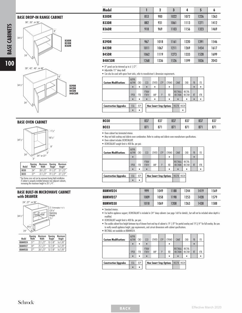
BASE DROP-IN RANGE CABINET
341/2”
8”
24”
30”, 33”, or 36”
B30DRB33DRB36DR
341/2”
24”
39”, 42”, 45”, or 48”
8”
B39DRB42DRB45DRB48CSDR
Model 1 2 3 4 5 6
B30DR 853 900 1022 1072 1226 1363
B33DR 882 931 1061 1113 1271 1412
B36DR 918 969 1103 1156 1323 1469
B39DR 967 1018 1161 1220 1391 1546
B42DR 1011 1067 1211 1269 1454 1617
B45DR 1062 1119 1273 1333 1528 1699
B48CSDR 1268 1336 1526 1599 1836 2043
• 8″ panel can be trimmed up to 6 1/2″.• Adjustable 15″ deep shelf.• Can also be used with apron front sinks, refer to manufacturer's dimension requirements.
Custom ModificationsAUTHLAUTHR CBO CCO CFNTO CFP CFRMO CMAT CND FB FD
• • • • • • •
FPEB FTKFTKAVFTKFV MIP P RD
RECTKALLRECTKBK
RECTKLRECTKR RT VTK
• • • • • • • • •
Construction Upgrades ECA ECP
• •
Non Smart Stop Options NSCFB NSCH
•
BASE OVEN CABINET
341/2”
24”
3”
3”
11/2”
191/2”
9”
24” or 27”
ModelOpeningWidth
MaximumWidth
OpeningHeight
MaximumHeight*
BO30 24″ 28 1/2″ 19 1/2″ 27 1/2″BO33 27″ 31 1/2″ 19 1/2″ 27 1/2″
*Top frame cross rail can be removed during field installationif cabinet is properly installed between two adjacent cabinets,increasing the maximum height to 28 1/4″.
BO30 837 837 837 837 837 837
BO33 871 871 871 871 871 871
• Oven cabinet has laminated interior.• May not hold cooktop and slide-in oven combination. Refer to cooktop and slide-in oven manufacturer specifications.• Oven cabinet includes OCINSTALLKIT.• OCINSTALLKIT weight limit is 400 lbs. per pair.
Custom ModificationsAUTHLAUTHR CBO CCO CFNTO CFP CFRMO CMAT CND FB FD
• • •
FPEB FTKFTKAVFTKFV MIP P RD
RECTKALLRECTKBK
RECTKLRECTKR RT VTK
• • • • • • •
Construction Upgrades ECA ECP
• •
Non Smart Stop Options NSCFB NSCH
BASE BUILT-IN MICROWAVE CABINETwith DRAWER
24”, 27”, or 30”
24”
137/8”OpeningHeight
3” (Trimmable 11/2”)
31/2”341/2”
21”, 24”, or 27”Opening Width
63/8”
ModelOpeningWidth
MaximumWidth
OpeningHeight
MaximumHeight
BBMWD24 21″ 22 1/2″ 13 7/8″ 16 7/8″BBMWD27 24″ 25 1/2″ 13 7/8″ 16 7/8″BBMWD30 27″ 28 1/2″ 13 7/8″ 16 7/8″
BBMWD24 999 1049 1188 1244 1419 1569
BBMWD27 1009 1058 1198 1253 1428 1579
BBMWD30 1018 1069 1208 1263 1438 1588
• Standard interior.• For built-in appliance support, OCINSTALLKIT is included in 24″ deep cabinets (see page 168 for details), but will not be included when depth is
modified.• OCINSTALLKIT weight limit is 400 lbs. per pair.• The usable cabinet face height between top of drawer front and top of cabinet is 19 1/8″ for partial overlay and 19 3/4″ for full overlay. Be sure
to verify overall appliance height, gap requirements, and cut-out dimensions with cabinet specifications.• RECTKALL not available on BBMWD24.
Custom ModificationsAUTHLAUTHR CBO CCO CFNTO CFP CFRMO CMAT CND FB FD
• • • • •
FPEB FTKFTKAVFTKFV MIP P RD
RECTKALLRECTKBK
RECTKLRECTKR RT VTK
• • • • • • •
Construction Upgrades ECA ECP
• •
Non Smart Stop Options NSCFB NSCH
BASE
CABI
NETS
100
Effective March 2020

BASE MICROWAVE CABINET withDRAWER
Opening Width
24”
341/2”17”OpeningHeight
41/2” (trimmable 3”)
21/2”
21”, 24”, or 27”
24”, 27”, or 30”
33/8”
ModelOpeningWidth
MaximumWidth
OpeningHeight
MaximumHeight
BMWD24 21″ 22 1/2″ 17″ 20″BMWD27 24″ 25 1/2″ 17″ 20″BMWD30 27″ 28 1/2″ 17″ 20″
Model 1 2 3 4 5 6
BMWD24 882 930 1058 1107 1270 1409
BMWD27 923 972 1106 1159 1328 1475
BMWD30 959 1010 1149 1204 1380 1530
• Reinforced plywood floor.• The usable cabinet face height between top of drawer front and top of cabinet is 23 1/2″ for partial overlay and full overlay. Be sure to verify overall
appliance height, gap requirements, and cut-out dimensions with cabinet specifications.• Matching Interior Plywood (MIP) standard.• RECTKALL not available on BMWD24.
Custom ModificationsAUTHLAUTHR CBO CCO CFNTO CFP CFRMO CMAT CND FB FD
• • • • • STD
FPEB FTKFTKAVFTKFV MIP P RD
RECTKALLRECTKBK
RECTKLRECTKR RT VTK
• • • STD • • • •
Construction Upgrades ECA ECP
STD
Non Smart Stop Options NSCFB NSCH
•
BASE MICROWAVE CABINET withDEEP DRAWER
24”
341/2”
16”OpeningHeight
24”, 27”, or 30”
21”, 24”, or 27”Opening Width
63/8”
11/2”
21/8”
ModelOpeningWidth
MaximumWidth
OpeningHeight
MaximumHeight
BMWD24DD 21″ 22 1/2″ 16″ 16″BMWD27DD 24″ 25 1/2″ 16″ 16″BMWD30DD 27″ 28 1/2″ 16″ 16″
BMWD24DD 882 930 1058 1107 1270 1409
BMWD27DD 923 972 1106 1159 1328 1475
BMWD30DD 1018 1069 1208 1263 1438 1588
• Reinforced plywood floor.• The usable cabinet face height between top of drawer front and top of cabinet is 19 1/8″ for partial overlay and 18 3/8″ for full overlay. Be sure
to verify overall appliance height, gap requirements, and cut-out dimensions with cabinet specifications.• Matching Interior Plywood (MIP) standard.• RECTKALL not available on BMWD24DD.
Custom ModificationsAUTHLAUTHR CBO CCO CFNTO CFP CFRMO CMAT CND FB FD
• • • • • STD
FPEB FTKFTKAVFTKFV MIP P RD
RECTKALLRECTKBK
RECTKLRECTKR RT VTK
• • • STD • • • •
Construction Upgrades ECA ECP
STD
Non Smart Stop Options NSCFB NSCH
BASE CORNER PENINSULA
241/4”
27”
F330
F330
BCP24 806 849 966 1012 1159 1287
• Cabinet width is 24″.• Adjustable full depth shelf.• Includes two 3″ fillers, shipped unattached. Fillers are required for drawer and door opening clearance of adjacent cabinets.• Unfinished toekick on front (B24) and back (BCP) of cabinet.• Will not accept roll trays.• Peninsula base cabinets are 1/4″ deeper to allow back paneling application on adjacent cabinets in a run with standard 24″ deep cabinets.• RECTKALL not available.
Custom ModificationsAUTHLAUTHR CBO CCO CFNTO CFP CFRMO CMAT CND FB FD
• • • • • • •
FPEB FTKFTKAVFTKFV MIP P RD
RECTKALLRECTKBK
RECTKLRECTKR RT VTK
• • • STD • STD • •
Construction Upgrades ECA ECP
• •
Non Smart Stop Options NSCFB NSCH
• •
BASE
CABI
NETS
101
Effective March 2020

BASE CORNER PENINSULA withFULL HEIGHT DOOR
241/4”
27”
F330
F330
Model 1 2 3 4 5 6
BCP24FH 1192 1256 1427 1497 1714 1903
• Cabinet width is 24″.• Adjustable full depth shelf.• Includes two 3″ fillers, shipped unattached. Fillers are required for drawer and door opening clearance of adjacent cabinets.• Unfinished toekick on front (B24) and back (BCP) of cabinet.• Will not accept roll trays.• Peninsula base cabinets are 1/4″ deeper to allow back paneling application on adjacent cabinets in a run with standard 24″ deep cabinets.• RECTKALL not available.
Custom ModificationsAUTHLAUTHR CBO CCO CFNTO CFP CFRMO CMAT CND FB FD
• • • • •
FPEB FTKFTKAVFTKFV MIP P RD
RECTKALLRECTKBK
RECTKLRECTKR RT VTK
• • • STD • STD • •
Construction Upgrades ECA ECP
• •
Non Smart Stop Options NSCFB NSCH
•
BASE
CABI
NETS
102
Effective March 2020
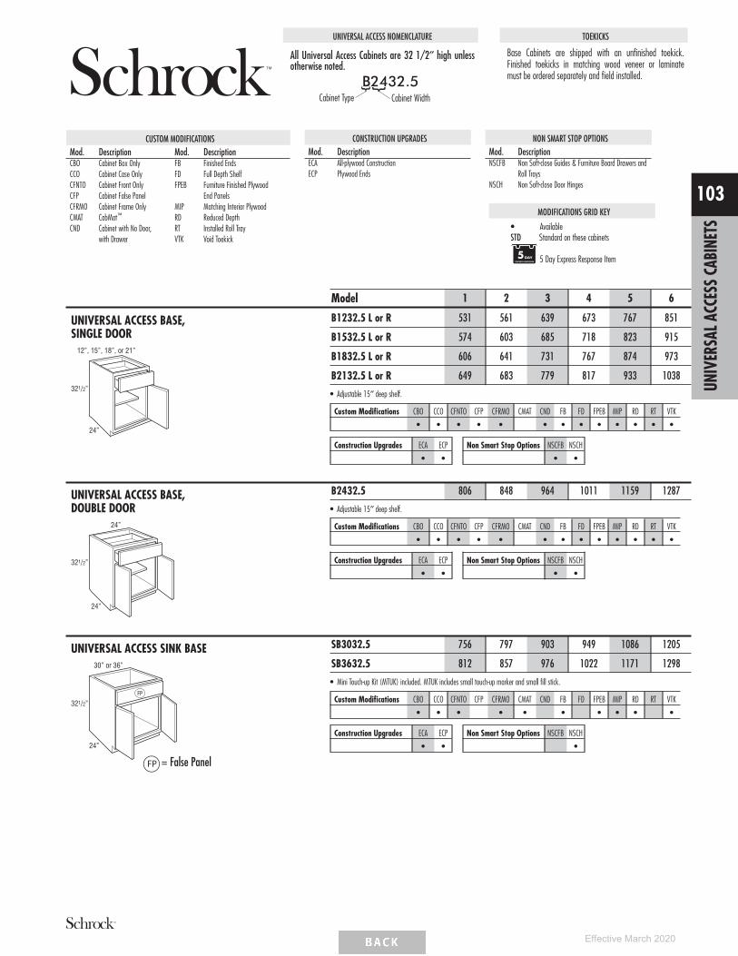
UNIVERSAL ACCESS NOMENCLATURE
All Universal Access Cabinets are 32 1/2″ high unlessotherwise noted.
B2432.5Cabinet Type Cabinet Width
TOEKICKS
Base Cabinets are shipped with an unfinished toekick.Finished toekicks in matching wood veneer or laminatemust be ordered separately and field installed.
CUSTOM MODIFICATIONSMod. Description Mod. DescriptionCBO Cabinet Box OnlyCCO Cabinet Case OnlyCFNTO Cabinet Front OnlyCFP Cabinet False PanelCFRMO Cabinet Frame OnlyCMAT CabMat™
CND Cabinet with No Door,with Drawer
FB Finished EndsFD Full Depth ShelfFPEB Furniture Finished Plywood
End PanelsMIP Matching Interior PlywoodRD Reduced DepthRT Installed Roll TrayVTK Void Toekick
CONSTRUCTION UPGRADESMod. DescriptionECA All-plywood ConstructionECP Plywood Ends
NON SMART STOP OPTIONSMod. DescriptionNSCFB Non Soft-close Guides & Furniture Board Drawers and
Roll TraysNSCH Non Soft-close Door Hinges
MODIFICATIONS GRID KEY
• AvailableSTD Standard on these cabinets
5 Day Express Response Item
UNIVERSAL ACCESS BASE,SINGLE DOOR
321/2”
24”
12”, 15”, 18”, or 21”
Model 1 2 3 4 5 6
B1232.5 L or R 531 561 639 673 767 851
B1532.5 L or R 574 603 685 718 823 915
B1832.5 L or R 606 641 731 767 874 973
B2132.5 L or R 649 683 779 817 933 1038
• Adjustable 15″ deep shelf.
Custom Modifications CBO CCO CFNTO CFP CFRMO CMAT CND FB FD FPEB MIP RD RT VTK
• • • • • • • • • • • • •
Construction Upgrades ECA ECP
• •
Non Smart Stop Options NSCFB NSCH
• •
UNIVERSAL ACCESS BASE,DOUBLE DOOR
321/2”
24”
24”
B2432.5 806 848 964 1011 1159 1287
• Adjustable 15″ deep shelf.
Custom Modifications CBO CCO CFNTO CFP CFRMO CMAT CND FB FD FPEB MIP RD RT VTK
• • • • • • • • • • • • •
Construction Upgrades ECA ECP
• •
Non Smart Stop Options NSCFB NSCH
• •
UNIVERSAL ACCESS SINK BASE
321/2”
24”
30” or 36”
FP
= False Panel
SB3032.5 756 797 903 949 1086 1205
SB3632.5 812 857 976 1022 1171 1298
• Mini Touch-up Kit (MTUK) included. MTUK includes small touch-up marker and small fill stick.
Custom Modifications CBO CCO CFNTO CFP CFRMO CMAT CND FB FD FPEB MIP RD RT VTK
• • • • • • • • • •
Construction Upgrades ECA ECP
• •
Non Smart Stop Options NSCFB NSCH
•
UNIV
ERSA
LACC
ESS
CABI
NETS
103
Effective March 2020

UNIVERSAL ACCESS SUPER LAZY SUSAN
321/2”
24”
36”36”36”
36”
24”
24”
87/8”
12”
335 /8”
183 /8”
Due to fixed shelf mounting,shelves cannot be retrofitted.
Model 1 2 3 4 5 6
SLS3632.5 L or R 2155 2201 2335 2385 2548 2691
• SLS3632.5 L or R wall width is 36″ x 36″.• Features two plywood revolving shelves with a 1″ plywood lip. Lower shelf is mounted to floor. Upper shelf is mounted to fixed shelf. Fixed shelf is
1/2″ thick laminated furniture board.• Decorative hardware screws must be countersunk to prevent scratching adjacent cabinets and face frame of SLS.• Integrated soft-close hinge not included.
Custom Modifications CBO CCO CFNTO CFP CFRMO CMAT CND FB FD FPEB MIP RD RT VTK
• • • • •
Construction Upgrades ECA ECP
• •
Non Smart Stop Options NSCFB NSCH
•
UNIVERSAL ACCESS THREE DRAWER BASE
321/2”
24”
15”, 18”, or 24”
3DB1532.5 794 818 887 913 990 1055
3DB1832.5 849 876 950 978 1060 1130
3DB2432.5 973 1004 1087 1119 1213 1295
• 1 shallow and 2 deep drawers.
Custom Modifications CBO CCO CFNTO CFP CFRMO CMAT CND FB FD FPEB MIP RD RT VTK
• • • • • • • •
Construction Upgrades ECA ECP
• •
Non Smart Stop Options NSCFB NSCH
•
UNIVERSAL ACCESS BASEMICROWAVE with DEEP DRAWER
24”
321/2”
14OpeningHeight
30”
63/8”
11/2”
2”
7/8”
27”Opening Width
BMWD3032.5DD 1171 1229 1389 1452 1654 1826
• 1 deep drawer below microwave.• Matching Interior Plywood (MIP) standard.
Custom Modifications CBO CCO CFNTO CFP CFRMO CMAT CND FB FD FPEB MIP RD RT VTK
• • • STD • STD • •
Construction Upgrades ECA ECP
STD
Non Smart Stop Options NSCFB NSCH
•
VANITY WALL SINK27”, 30”, or 33”
201/4”
23”
VWS2723 676 676 676 676 676 676
VWS3023 687 687 687 687 687 687
VWS3323 699 699 699 699 699 699
• Matching Interior Plywood (MIP) standard.• Recommended installation height of 32″ high with 9″ of clearance below.• Front panel is attached with clips for easy removal for access to plumbing.• Finished veneer plywood exterior and interior.• For proper installation, cabinet must be secured on each side through both the top and bottom of the back panel into wall studs. Installation
instructions and required 3 1/2″ installation screws included, standard 2 1/2″ installation screws are not sufficient in this application.• Features a full cabinet top that can be routed for sink installation.• Approximate weight limit is 400 lbs. per cabinet (includes weight of the cabinet, countertop and contents). Proper installation is required and
additional bracing may be required.• Includes connector clips to mount the sink base to the Removable Vanity Sink Base (RVWS..32). RVWS..32 not included, see below.
Custom Modifications CBO CCO CFNTO CFP CFRMO CMAT CND FB FD FPEB MIP RD RT VTK
STD STD
Construction Upgrades ECA ECP
STD
Non Smart Stop Options NSCFB NSCH
UNIV
ERSA
LACC
ESS
CABI
NETS
104
Effective March 2020

REMOVABLE VANITY SINK BASE,21″ DEEP
32”
21”
30”, 33”, or 36”
FP
Model 1 2 3 4 5 6
RVWS3032 759 801 910 954 1092 1212
RVWS3332 772 814 926 972 1113 1233
RVWS3632 790 835 948 996 1139 1264
• Must be ordered with Vanity Wall Sink (VWS..23), not designed to be a stand-alone unit.– RVWS3032 is compatible with VWS2723– RVWS3332 is compatible with VWS3023– RVWS3632 is compatible with VWS3323
• Cabinet is able to be removed for handicap accessible use.• Includes connector clips to mount the sink base to the Vanity Wall Sink (VWS..23).
Custom Modifications CBO CCO CFNTO CFP CFRMO CMAT CND FB FD FPEB MIP RD RT VTK
• • • STD •
Construction Upgrades ECA ECP
STD
Non Smart Stop Options NSCFB NSCH
•
UNIV
ERSA
LACC
ESS
CABI
NETS
105
Effective March 2020

TALL CABINET NOMENCLATURE
Cabinet nomenclature with AH represents uppersections with doors that align with 24″ or 27″ highcabinets.
Cabinet Type Cabinet DepthCabinet Width Cabinet Height
CUSTOM MODIFICATIONSMod. Description Mod. DescriptionAUTHL Authentic End - LeftAUTHR Authentic End - RightCBO Cabinet Box OnlyCCO Cabinet Case OnlyCFNTO Cabinet Front OnlyCFRMO Cabinet Frame OnlyCND Cabinet with No Door,
with DrawerFB Finished EndsFD Full Depth Shelf
FPEB Furniture Finished PlywoodEnd Panels
FTK Flush ToekickFTKAV Flush Toekick ArchFTKFV Flush Toekick FurnitureMIP Matching Interior PlywoodRD Reduced DepthRECTKL Recessed Toekick LeftRECTKR Recessed Toekick RightRT Installed Roll TrayVTK Void Toekick
CONSTRUCTION UPGRADESMod. DescriptionECA All-plywood ConstructionECP Plywood Ends
NON SMART STOP OPTIONSMod. DescriptionNSCFB Non Soft-close Guides & Furniture Board Drawers and
Roll TraysNSCH Non Soft-close Door Hinges
MODIFICATIONS GRID KEY
• AvailableSTD Standard on these cabinets
Smart Solutions™ Organization Cabinet
UTILITY, 84″, 87″, 90″, 93″, or96″ TALL, 12″ DEEP
12”
12”, 15”, 18”, 21”, or 24”
15” or 18”FrameOpeningHeight
581/2”FrameOpeningHeight
84”or
87”
12”
15” or 18”FrameOpeningHeight
581/2”FrameOpeningHeight
24”, 27”, 30”, 33”, or 36”
84”or
87”
U128412 L or RU158412 L or RU188412 L or RU218412 L or RU248412 L or R
U128712 L or RU158712 L or RU188712 L or RU218712 L or RU248712 L or R
U248412U278412U308412U338412U368412
U248712U278712U308712U338712U368712
Model 1 2 3 4 5 6
U128412 L or R 966 1010 1128 1177 1332 1470
U158412 L or R 1007 1050 1175 1226 1389 1532
U188412 L or R 1011 1059 1180 1231 1394 1540
U218412 L or R 1149 1202 1344 1402 1590 1755
U248412 L or R 1287 1348 1506 1572 1783 1972
U248412 1373 1438 1610 1679 1906 2107
U278412 1417 1482 1662 1733 1966 2173
U308412 1461 1528 1713 1786 2027 2241
U338412 1560 1633 1829 1909 2166 2395
U368412 1660 1736 1947 2032 2304 2546
• Four full depth adjustable shelves are included but shipped separately.• Utility cabinets with depths of 12″ or less must be installed to wall studs or onto the end of another tall cabinet.• Tall mitered door styles will feature one center panel, other styles will feature two center panels.
U128712 L or R 992 1038 1160 1211 1371 1514
U158712 L or R 1035 1082 1208 1261 1428 1577
U188712 L or R 1144 1197 1339 1397 1583 1749
U218712 L or R 1234 1290 1444 1508 1710 1890
U248712 L or R 1324 1386 1550 1619 1836 2029
U248712 1414 1479 1656 1730 1962 2168
U278712 1458 1525 1710 1784 2024 2238
U308712 1502 1572 1761 1839 2087 2307
U338712 1605 1679 1883 1965 2231 2466
U368712 1708 1786 2003 2092 2374 2623
• Four full depth adjustable shelves are included but shipped separately.• Utility cabinets with depths of 12″ or less must be installed to wall studs or onto the end of another tall cabinet.• Tall mitered door styles will feature one center panel, other styles will feature two center panels.• FTKAV and FTKFV not available on W128412 L or R and W128712 L or R.
Custom ModificationsAUTHLAUTHR CBO CCO CFNTO CFRMO CND FB FD FPEB FTK
FTKAVFTKFV MIP RD
RECTKLRECTKR RT VTK
• • • • • • • • • • • •
Construction Upgrades ECA ECP
• •
Non Smart Stop Options NSCFB NSCH
•
TALL
CABI
NETS
106
Effective March 2020

UTILITY, 84″, 87″, 90″, 93″, or96″ TALL, 12″ DEEP (cont’d)
21”FrameOpeningHeight
581/2”FrameOpeningHeight
90”
12”
12”, 15”, 18”, 21”, or 24”
U129012AH L or RU159012AH L or RU189012AH L or RU219012AH L or RU249012AH L or R
90”
12”
581/2”FrameOpeningHeight
21”FrameOpeningHeight
24”, 27”, 30”, 33”, or 36”
U249012AHU279012AHU309012AHU339012AHU369012AH
Model 1 2 3 4 5 6
U129012AH L or R 1000 1045 1167 1220 1381 1525
U159012AH L or R 1042 1089 1216 1269 1438 1587
U189012AH L or R 1177 1231 1379 1438 1630 1802
U219012AH L or R 1256 1313 1470 1535 1740 1923
U249012AH L or R 1332 1396 1561 1631 1850 2043
U249012AH 1424 1490 1668 1742 1977 2185
U279012AH 1468 1536 1721 1796 2038 2255
U309012AH 1513 1582 1775 1852 2102 2325
U339012AH 1616 1691 1896 1980 2247 2483
U369012AH 1719 1798 2017 2107 2391 2643
• AH represents upper section alignment with doors on 24″ or 27″ high cabinets.• Five full depth adjustable shelves are included but shipped separately.• Utility cabinets with depths of 12″ or less must be installed to wall studs or onto the end of another tall cabinet.• Tall mitered door styles will feature one center panel, other styles will feature two center panels.• FTKAV and FTKFV not available on U129012AH L or R.
Custom ModificationsAUTHLAUTHR CBO CCO CFNTO CFRMO CND FB FD FPEB FTK
FTKAVFTKFV MIP RD
RECTKLRECTKR RT VTK
• • • • • • • • • • • •
Construction Upgrades ECA ECP
• •
Non Smart Stop Options NSCFB NSCH
•
TALL
CABI
NETS
107
Effective March 2020

UTILITY, 84″, 87″, 90″, 93″, or96″ TALL, 12″ DEEP (cont’d)
581/2”FrameOpeningHeight
93”
12”
12”, 15”, 18”, 21”, or 24”
24” FrameOpeningHeight
U129312AH L or RU159312AH L or RU189312AH L or RU219312AH L or RU249312AH L or R
93”
12”
24”, 27”, 30”, 33”, or 36”
581/2”FrameOpeningHeight
24” FrameOpeningHeight
U249312AHU279312AHU309312AHU339312AHU369312AH
27”FrameOpeningHeight
581/2”FrameOpeningHeight
96”
12”
12”, 15”, 18”, 21”, or 24”
U129612 L or RU159612 L or RU189612 L or RU219612 L or RU249612 L or R
96”
12”
27”FrameOpeningHeight
581/2”FrameOpeningHeight
24”, 27”, 30”, 33”, or 36”
U249612U279612U309612U339612U369612
Model 1 2 3 4 5 6
U129312AH L or R 1034 1080 1209 1262 1430 1580
U159312AH L or R 1076 1127 1260 1314 1491 1647
U189312AH L or R 1220 1274 1428 1492 1691 1871
U219312AH L or R 1300 1360 1523 1593 1806 1995
U249312AH L or R 1382 1444 1619 1690 1919 2119
U249312AH 1473 1543 1730 1807 2051 2266
U279312AH 1520 1594 1786 1864 2116 2338
U309312AH 1568 1641 1841 1921 2181 2411
U339312AH 1675 1753 1964 2052 2331 2576
U369312AH 1780 1864 2089 2183 2479 2739
• AH represents upper section alignment with doors on 24″ or 27″ high cabinets.• Separate pedestal base included but shipped separately on 93″ tall.• Five full depth adjustable shelves are included but shipped separately.• Utility cabinets with depths of 12″ or less must be installed to wall studs or onto the end of another tall cabinet.• Tall mitered door styles will feature one center panel, other styles will feature two center panels.
U129612 L or R 1034 1080 1209 1262 1430 1580
U159612 L or R 1076 1127 1260 1314 1491 1647
U189612 L or R 1220 1274 1428 1492 1691 1871
U219612 L or R 1300 1360 1523 1593 1806 1995
U249612 L or R 1382 1444 1619 1690 1919 2119
U249612 1473 1543 1730 1807 2051 2266
U279612 1520 1594 1786 1864 2116 2338
U309612 1568 1641 1841 1921 2181 2411
U339612 1675 1753 1964 2052 2331 2576
U369612 1780 1864 2089 2183 2479 2739
• Separate pedestal base included but shipped separately on 96″ tall.• Six full depth adjustable shelves are included but shipped separately.• Utility cabinets with depths of 12″ or less must be installed to wall studs or onto the end of another tall cabinet.• Tall mitered door styles will feature one center panel, other styles will feature two center panels.
Custom ModificationsAUTHLAUTHR CBO CCO CFNTO CFRMO CND FB FD FPEB FTK
FTKAVFTKFV MIP RD
RECTKLRECTKR RT VTK
• • • • • • • •
Construction Upgrades ECA ECP
• •
Non Smart Stop Options NSCFB NSCH
•
TALL
CABI
NETS
108
Effective March 2020

UTILITY, 84″, 87″, 90″, 93″, or96″ TALL, 24″ DEEP
15” or 18”FrameOpeningHeight
581/2”FrameOpeningHeight
24”
12”, 15”, 18”, 21”, or 24”
84”or
87”
U128424 L or RU158424 L or RU188424 L or RU218424 L or RU248424 L or R
U128724 L or RU158724 L or RU188724 L or RU218724 L or RU248724 L or R
24”
15” or 18”FrameOpeningHeight
581/2”FrameOpeningHeight
24”, 27”, 30”, 33”, or 36”
84”or
87”
U248424U278424U308424U338424U368424
U248724U278724U308724U338724U368724
581/2”FrameOpeningHeight
90”
24”
12”, 15”, 18”, 21”, or 24”
21”FrameOpeningHeight
U129024AH L or RU159024AH L or RU189024AH L or RU219024AH L or RU249024AH L or R
90”
24”
581/2”FrameOpeningHeight
21”FrameOpeningHeight
24”, 27”, 30”, 33”, or 36”
U249024AHU279024AHU309024AHU339024AHU369024AH
Model 1 2 3 4 5 6
U128424 L or R 1195 1244 1374 1432 1612 1775
U158424 L or R 1244 1295 1432 1491 1679 1849
U188424 L or R 1395 1453 1611 1677 1893 2086
U218424 L or R 1481 1543 1714 1783 2014 2220
U248424 L or R 1567 1634 1815 1891 2135 2352
U248424 1667 1740 1932 2014 2275 2508
U278424 1717 1793 1991 2076 2345 2586
U308424 1768 1845 2051 2137 2415 2663
U338424 1881 1964 2187 2279 2576 2840
U368424 1996 2085 2321 2422 2737 3018
• Four full depth adjustable shelves are included but shipped separately.• Depth can be reduced to a minimum of 15″.• Tall mitered door styles will feature one center panel, other styles will feature two center panels.
U128724 L or R 1225 1276 1413 1470 1656 1825
U158724 L or R 1277 1327 1472 1531 1726 1900
U188724 L or R 1431 1494 1656 1726 1947 2147
U218724 L or R 1520 1586 1761 1835 2072 2284
U248724 L or R 1611 1678 1865 1944 2196 2421
U248724 1712 1787 1988 2070 2340 2580
U278724 1763 1842 2048 2134 2413 2659
U308724 1815 1895 2107 2198 2484 2739
U338724 1933 2019 2246 2344 2650 2922
U368724 2051 2142 2385 2487 2814 3105
• Four full depth adjustable shelves are included but shipped separately.• Depth can be reduced to a minimum of 15″.• Tall mitered door styles will feature one center panel, other styles will feature two center panels.
U129024AH L or R 1231 1284 1423 1480 1668 1838
U159024AH L or R 1285 1335 1481 1540 1738 1913
U189024AH L or R 1440 1503 1667 1738 1961 2163
U219024AH L or R 1530 1598 1774 1848 2087 2301
U249024AH L or R 1621 1689 1878 1957 2212 2438
U249024AH 1723 1798 2001 2086 2357 2598
U279024AH 1775 1854 2061 2149 2429 2678
U309024AH 1827 1909 2121 2213 2502 2758
U339024AH 1948 2032 2263 2360 2668 2942
U369024AH 2065 2157 2402 2504 2833 3126
• AH represents upper section alignment with doors on 24″ or 27″ high cabinets.• Five full depth adjustable shelves are included but shipped separately.• Depth can be reduced to a minimum of 15″.• Tall mitered door styles will feature one center panel, other styles will feature two center panels.• FTKAV and FTKFV not available on U128424 L or R, U128724 L or R, and U129024AH L or R.
Custom ModificationsAUTHLAUTHR CBO CCO CFNTO CFRMO CND FB FD FPEB FTK
FTKAVFTKFV MIP RD
RECTKLRECTKR RT VTK
• • • • • • • • • • • • • •
Construction Upgrades ECA ECP
• •
Non Smart Stop Options NSCFB NSCH
•
TALL
CABI
NETS
109
Effective March 2020
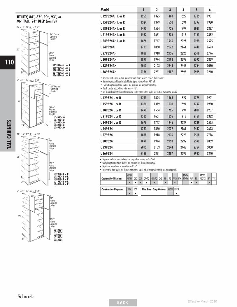
UTILITY, 84″, 87″, 90″, 93″, or96″ TALL, 24″ DEEP (cont’d)
581/2”FrameOpeningHeight
93”
24”
12”, 15”, 18”, 21”, or 24”
24” FrameOpeningHeight
U129324AH L or RU159324AH L or RU189324AH L or RU219324AH L or RU249324AH L or R
93”
24”
24”, 27”, 30”, 33”, or 36”
581/2”FrameOpeningHeight
24” FrameOpeningHeight
U249324AHU279324AHU309324AHU339324AHU369324AH
27”FrameOpeningHeight
581/2”FrameOpeningHeight
96”
24”
12”, 15”, 18”, 21”, or 24”
U129624 L or RU159624 L or RU189624 L or RU219624 L or RU249624 L or R
96”
24”
27”FrameOpeningHeight
581/2”FrameOpeningHeight
24”, 27”, 30”, 33”, or 36”
U249624U279624U309624U339624U369624
Model 1 2 3 4 5 6
U129324AH L or R 1269 1325 1468 1529 1725 1901
U159324AH L or R 1324 1379 1530 1594 1797 1980
U189324AH L or R 1490 1554 1725 1797 2031 2237
U219324AH L or R 1582 1651 1836 1913 2161 2382
U249324AH L or R 1676 1747 1946 2027 2289 2525
U249324AH 1783 1860 2072 2161 2442 2693
U279324AH 1838 1918 2136 2226 2518 2776
U309324AH 1891 1974 2198 2292 2592 2859
U339324AH 2013 2103 2344 2443 2764 3050
U369324AH 2136 2231 2487 2595 2935 3240
• AH represents upper section alignment with doors on 24″ or 27″ high cabinets.• Separate pedestal base included but shipped separately on 93″ tall.• Five full depth adjustable shelves are included but shipped separately.• Depth can be reduced to a minimum of 15″.• Tall mitered door styles will feature one center panel, other styles will feature two center panels.
U129624 L or R 1269 1325 1468 1529 1725 1901
U159624 L or R 1324 1379 1530 1594 1797 1980
U189624 L or R 1490 1554 1725 1797 2031 2237
U219624 L or R 1582 1651 1836 1913 2161 2382
U249624 L or R 1676 1747 1946 2027 2289 2525
U249624 1783 1860 2072 2161 2442 2693
U279624 1838 1918 2136 2226 2518 2776
U309624 1891 1974 2198 2292 2592 2859
U339624 2013 2103 2344 2443 2764 3050
U369624 2136 2231 2487 2595 2935 3240
• Separate pedestal base included but shipped separately on 96″ tall.• Six full depth adjustable shelves are included but shipped separately.• Depth can be reduced to a minimum of 15″.• Tall mitered door styles will feature one center panel, other styles will feature two center panels.
Custom ModificationsAUTHLAUTHR CBO CCO CFNTO CFRMO CND FB FD FPEB FTK
FTKAVFTKFV MIP RD
RECTKLRECTKR RT VTK
• • • • • • • • • •
Construction Upgrades ECA ECP
• •
Non Smart Stop Options NSCFB NSCH
•
TALL
CABI
NETS
110
Effective March 2020

UTILITY with ROLL TRAYS, 84″, 87″,90″, 93″, or 96″ TALL , 24″ DEEP12”, 15”, 18”, 21”, or 24”
24”
15” or 18”FrameOpeningHeight
581/2”FrameOpeningHeight
84”or
87”
U128424RT L or RU158424RT L or RU188424RT L or RU218424RT L or RU248424RT L or R
U128724RT L or RU158724RT L or RU188724RT L or RU218724RT L or RU248724RT L or R
24”
15” or 18”FrameOpeningHeight
581/2”FrameOpeningHeight
24”, 27”, 30”, 33”, or 36”
84”or
87”
U248424RTU278424RTU308424RTU338424RTU368424RT
U248724RTU278724RTU308724RTU338724RTU368724RT
12”, 15”, 18”, 21”, or 24”
90”
24”
581/2”FrameOpeningHeight
21”FrameOpeningHeight
U129024RTAH L or RU159024RTAH L or RU189024RTAH L or RU219024RTAH L or RU249024RTAH L or R
24”
90”581/2”FrameOpeningHeight
21”FrameOpeningHeight
24”, 27”, 30”, 33”, or 36”
U249024RTAHU279024RTAHU309024RTAHU339024RTAHU369024RTAH
Model 1 2 3 4 5 6
U128424RT L or R 1705 1754 1884 1942 2122 2285
U158424RT L or R 1754 1805 1942 2001 2189 2359
U188424RT L or R 1905 1963 2121 2187 2403 2596
U218424RT L or R 1991 2053 2224 2293 2524 2730
U248424RT L or R 2077 2144 2325 2401 2645 2862
U248424RT 2177 2250 2442 2524 2785 3018
U278424RT 2227 2303 2501 2586 2855 3096
U308424RT 2278 2355 2561 2647 2925 3173
U338424RT 2391 2474 2697 2789 3086 3350
U368424RT 2506 2595 2831 2932 3247 3528
• Four roll trays are included; installed in cabinet.• Depth can be reduced to a minimum of 18″.• Tall mitered door styles will feature one center panel, other styles will feature two center panels.
U128724RT L or R 1735 1786 1923 1980 2166 2335
U158724RT L or R 1787 1837 1982 2041 2236 2410
U188724RT L or R 1941 2004 2166 2236 2457 2657
U218724RT L or R 2030 2096 2271 2345 2582 2794
U248724RT L or R 2121 2188 2375 2454 2706 2931
U248724RT 2222 2297 2498 2580 2850 3090
U278724RT 2273 2352 2558 2644 2923 3169
U308724RT 2325 2405 2617 2708 2994 3249
U338724RT 2443 2529 2756 2854 3160 3432
U368724RT 2561 2652 2895 2997 3324 3615
• Four roll trays are included; installed in cabinet.• Depth can be reduced to a minimum of 18″.• Tall mitered door styles will feature one center panel, other styles will feature two center panels.
U129024RTAH L or R 1741 1794 1933 1990 2178 2348
U159024RTAH L or R 1795 1845 1991 2050 2248 2423
U189024RTAH L or R 1950 2013 2177 2248 2471 2673
U219024RTAH L or R 2040 2108 2284 2358 2597 2811
U249024RTAH L or R 2131 2199 2388 2467 2722 2948
U249024RTAH 2233 2308 2511 2596 2867 3108
U279024RTAH 2285 2364 2571 2659 2939 3188
U309024RTAH 2337 2419 2631 2723 3012 3268
U339024RTAH 2458 2542 2773 2870 3178 3452
U369024RTAH 2575 2667 2912 3014 3343 3636
• AH represents upper section alignment with doors on 24″ or 27″ high cabinets.• Four roll trays are included; installed in cabinet.• Depth can be reduced to a minimum of 18″.• Tall mitered door styles will feature one center panel, other styles will feature two center panels.• FTKAV and FTKFV not available on U128424RT L or R, U128724RT L or R, and U129024RTAH L or R.
Custom ModificationsAUTHLAUTHR CBO CCO CFNTO CFRMO CND FB FD FPEB FTK
FTKAVFTKFV MIP RD
RECTKLRECTKR RT VTK
• • • • • • • • • • • • •
Construction Upgrades ECA ECP
• •
Non Smart Stop Options NSCFB NSCH
• •
TALL
CABI
NETS
111
Effective March 2020

UTILITY with ROLL TRAYS, 84″, 87″,90″, 93″, or 96″ TALL , 24″ DEEP(cont’d)12”, 15”, 18”, 21”, or 24”
93”
24”
581/2”FrameOpeningHeight
24” FrameOpeningHeight
U129324RTAH L or RU159324RTAH L or RU189324RTAH L or RU219324RTAH L or RU249324RTAH L or R
24”
24”, 27”, 30”, 33”, or 36”
93”
581/2”FrameOpeningHeight
24” FrameOpeningHeight
U249324RTAHU279324RTAHU309324RTAHU339324RTAHU369324RTAH
12”, 15”, 18”, 21”, or 24”
96”
24”
581/2”FrameOpeningHeight
27”FrameOpeningHeight
U129624RT L or RU159624RT L or RU189624RT L or RU219624RT L or RU249624RT L or R
96”
24”
24”, 27”, 30”, 33”, or 36”
27”FrameOpeningHeight
581/2”FrameOpeningHeight
U249624RTU279624RTU309624RTU339624RTU369624RT
Model 1 2 3 4 5 6
U129324RTAH L or R 1779 1835 1978 2039 2235 2411
U159324RTAH L or R 1834 1889 2040 2104 2307 2490
U189324RTAH L or R 2000 2064 2235 2307 2541 2747
U219324RTAH L or R 2092 2161 2346 2423 2671 2892
U249324RTAH L or R 2186 2257 2456 2537 2799 3035
U249324RTAH 2293 2370 2582 2671 2952 3203
U279324RTAH 2348 2428 2646 2736 3028 3286
U309324RTAH 2401 2484 2708 2802 3102 3369
U339324RTAH 2523 2613 2854 2953 3274 3560
U369324RTAH 2646 2741 2997 3105 3445 3750
• AH represents upper section alignment with doors on 24″ or 27″ high cabinets.• Separate pedestal base included but shipped separately on 93″ tall.• Four roll trays are included; installed in cabinet.• Depth can be reduced to a minimum of 18″.• Tall mitered door styles will feature one center panel, other styles will feature two center panels.
U129624RT L or R 1779 1835 1978 2039 2235 2411
U159624RT L or R 1834 1889 2040 2104 2307 2490
U189624RT L or R 2000 2064 2235 2307 2541 2747
U219624RT L or R 2092 2161 2346 2423 2671 2892
U249624RT L or R 2186 2257 2456 2537 2799 3035
U249624RT 2293 2370 2582 2671 2952 3203
U279624RT 2348 2428 2646 2736 3028 3286
U309624RT 2401 2484 2708 2802 3102 3369
U339624RT 2523 2613 2854 2953 3274 3560
U369624RT 2646 2741 2997 3105 3445 3750
• Separate pedestal base included but shipped separately on 96″ tall.• Four roll trays are included; installed in cabinet.• Depth can be reduced to a minimum of 18″.• Tall mitered door styles will feature one center panel, other styles will feature two center panels.
Custom ModificationsAUTHLAUTHR CBO CCO CFNTO CFRMO CND FB FD FPEB FTK
FTKAVFTKFV MIP RD
RECTKLRECTKR RT VTK
• • • • • • • • •
Construction Upgrades ECA ECP
• •
Non Smart Stop Options NSCFB NSCH
• •
TALL
CABI
NETS
112
Effective March 2020

UTILITY ORGANIZER CABINET, 84″,87″, 90″, 93″, or 96″ TALL, 6″ DEEP,24″ WIDE
6”
24”15” or 18”FrameOpeningHeight
581/2”FrameOpeningHeight
791/2”
127/16”
13/64”
261/64”
33/32”
821/2”or
UOC24846UOC24876
6”
24”
58
21” or 24”FrameOpeningHeight
1/2”FrameOpeningHeight
851/2”or
881/2”
127/16”
13/64”
261/64”
33/32”
UOC24906AHUOC24936AH
24”
581/2”FrameOpeningHeight
27”FrameOpeningHeight
911/2”
127/16”
13/64”
261/64”
33/32”6”
UOC24966
Model 1 2 3 4 5 6
UOC24846 1373 1438 1610 1679 1906 2107
UOC24876 1414 1479 1656 1730 1962 2168
• Includes four adjustable shelves shipped separate (not installed).• 3/4″ thick veneered plywood flush ends.• Designed to be installed onto an adjacent 24″ deep Tall cabinet or 24″ wide Tall End Panel.• For proper installation, adjacent cabinet must have FPEB or 1/4″ skin applied.• 6″ overlay fillers can be used on the side to add a decorative touch.• Utility cabinets with depths of 12″ or less must be installed to wall studs or onto the end of another tall cabinet.• Does not include toeboard or pedestal.• Tall mitered door styles will feature one center panel, other styles will feature two center panels.
UOC24906AH 1424 1490 1668 1742 1977 2185
UOC24936AH 1473 1543 1730 1807 2051 2266
• AH represents upper section alignment with doors on 24″ or 27″ high cabinets.• Includes five adjustable shelves shipped separate (not installed).• 3/4″ thick veneered plywood flush ends.• Designed to be installed onto an adjacent 24″ deep Tall cabinet or 24″ wide Tall End Panel.• For proper installation, adjacent cabinet must have FPEB or 1/4″ skin applied.• 6″ overlay fillers can be used on the side to add a decorative touch.• Utility cabinets with depths of 12″ or less must be installed to wall studs or onto the end of another tall cabinet.• Does not include toeboard or pedestal.• Tall mitered door styles will feature one center panel, other styles will feature two center panels.
UOC24966 1473 1543 1730 1807 2051 2266
• Includes six adjustable shelves shipped separate (not installed).• 3/4″ thick veneered plywood flush ends.• Designed to be installed onto an adjacent 24″ deep Tall cabinet or 24″ wide Tall End Panel.• For proper installation, adjacent cabinet must have FPEB or 1/4″ skin applied.• 6″ overlay fillers can be used on the side to add a decorative touch.• Utility cabinets with depths of 12″ or less must be installed to wall studs or onto the end of another tall cabinet.• Does not include toeboard or pedestal.• Tall mitered door styles will feature one center panel, other styles will feature two center panels.
Custom ModificationsAUTHLAUTHR CBO CCO CFNTO CFRMO CND FB FD FPEB FTK
FTKAVFTKFV MIP RD
RECTKLRECTKR RT VTK
• • • • STD •
Construction Upgrades ECA ECP
•
Non Smart Stop Options NSCFB NSCH
•
TALL
CABI
NETS
113
Effective March 2020

SINGLE OVEN CABINET, 84″, 87″, or90″ TALL, 24″ DEEP
84”87”90”
24”
30” or 33”
11/2” or3” Stile
11/2” or3” Stile
B
C
5”
FrameOpeningHeight
6”
201/2”
11/2”
Max Cut-out (Shaded)
Toekick 41/2”
A
6”
Model 1 2 3 4 5 6
OSB308424 1550 1635 1860 1950 2232 2481
OSB338424 1659 1746 1991 2086 2388 2652
OSB308724 1658 1746 1991 2085 2388 2651
OSB338724 1770 1862 2122 2225 2545 2828
OSB309024 1685 1774 2023 2120 2426 2694
OSB339024 1799 1891 2155 2259 2585 2872
• Uses face mount hinges, doors and drawer fronts have a consistent width reveal for full overlay (1/4″) and partial overlay (1″).• Oven cavity is standard interior.• Base section will utilize a full depth shelf.• Upper section on 90″ tall has one full depth adjustable shelf.• All top and bottom cross rails are 1 1/2″ wide.• All cabinets have 3″ stiles on frame.• Be sure to confirm a heat shield is built into your appliance by the manufacturer or install the heat shield included with your appliance. Heat shields
are sold separately as an accessory.• Depth can be reduced to a minimum of 18″.• Shelf support for oven not included; for built-in appliance support brackets, use OCINSTALLKIT (included in 24″ deep cabinets). OCINSTALLKIT weight
limit is 400 lbs. per pair.• Oven cabinets feature an open back in cut-out area designed to improve field appliance installation.
A B C Door Height
Frame Opening Cut-out Width Cut-out Height (Upper Section)Height Min. Max. Min. Max. Partial Overlay Full Overlay
OSB308424 15″ 24″ 28 1/2″ 22 1/2″ 31 1/2″ 16″ 17 1/2″OSB338424 15″ 27″ 31 1/2″ 22 1/2″ 31 1/2″ 16″ 17 1/2″OSB308724 18″ 24″ 28 1/2″ 22 1/2″ 31 1/2″ 19″ 20 1/2″OSB338724 18″ 27″ 31 1/2″ 22 1/2″ 31 1/2″ 19″ 20 1/2″OSB309024 21″ 24″ 28 1/2″ 22 1/2″ 31 1/2″ 22″ 23 1/2″OSB339024 21″ 27″ 31 1/2″ 22 1/2″ 31 1/2″ 22″ 23 1/2″
Maximum cut-out dimension will allow 1/4″ reveal for doors and drawer fronts on full overlay and 1″ for partialoverlay for trim kit face clearance.
Custom ModificationsAUTHLAUTHR CBO CCO CFNTO CFRMO CND FB FD FPEB FTK
FTKAVFTKFV MIP RD
RECTKLRECTKR RT VTK
• • • • • • • STD • • • • • • • •
Construction Upgrades ECA ECP
• •
Non Smart Stop Options NSCFB NSCH
• •
TALL
CABI
NETS
114
Effective March 2020

SINGLE OVEN CABINET,93″ or 96″ TALL, 24″ DEEP
93”96”
24”
30” or 33”
11/2” or3” Stile
11/2” or3” Stile
B
C
5”
FrameOpeningHeight
6”
201/2”
11/2”
Max Cut-out (Shaded)
Pedestal
A
6”
Model 1 2 3 4 5 6
OSB309324 1823 1917 2184 2289 2618 2912
OSB339324 1933 2037 2320 2434 2783 3092
OSB309624 1823 1917 2184 2289 2618 2912
OSB339624 1933 2037 2320 2434 2783 3092
• Uses face mount hinges, doors and drawer fronts have a consistent width reveal for full overlay (1/4″) and partial overlay (1″).• Oven cavity is standard interior.• Base section will utilize a full depth shelf.• Includes adjustable shelves in upper section:
93″ tall - one shelf96″ tall - two shelves
• Separate pedestal base included but shipped separately on 93″ and 96″ tall.• All top and bottom cross rails are 1 1/2″ wide.• All cabinets have 3″ stiles on frame.• Be sure to confirm a heat shield is built into your appliance by the manufacturer or install the heat shield included with your appliance. Heat shields
are sold separately as an accessory.• Depth can be reduced to a minimum of 18″.• Shelf support for oven not included; for built-in appliance support brackets, use OCINSTALLKIT (included in 24″ deep cabinets). OCINSTALLKIT weight
limit is 400 lbs. per pair.• Oven cabinets feature an open back in cut-out area designed to improve field appliance installation.
A B C Door Height
Frame Opening Cut-out Width Cut-out Height (Upper Section)Height Min. Max. Min. Max. Partial Overlay Full Overlay
OSB309324 24″ 24″ 28 1/2″ 22 1/2″ 31 1/2″ 25″ 26 1/2″OSB339324 24″ 27″ 31 1/2″ 22 1/2″ 31 1/2″ 25″ 26 1/2″OSB309624 27″ 24″ 28 1/2″ 22 1/2″ 31 1/2″ 28″ 29 1/2″OSB339624 27″ 27″ 31 1/2″ 22 1/2″ 31 1/2″ 28″ 29 1/2″
Maximum cut-out dimension will allow 1/4″ reveal for doors and drawer fronts on full overlay and 1″ for partialoverlay for trim kit face clearance.
Custom ModificationsAUTHLAUTHR CBO CCO CFNTO CFRMO CND FB FD FPEB FTK
FTKAVFTKFV MIP RD
RECTKLRECTKR RT VTK
• • • • • • • STD • • • •
Construction Upgrades ECA ECP
• •
Non Smart Stop Options NSCFB NSCH
• •
TALL
CABI
NETS
115
Effective March 2020

OVEN MICROWAVE COMBO CABINET,84″, 87″, or 90″ TALL, 24″ DEEP
84”87”90”
24”
30” or 33”
3”Stile
3”Stile
Max Cut-out (Shaded)
A
B
C
15”
9”
FrameOpeningHeight
Toekick 41/2”
9”
Model 1 2 3 4 5 6
OCS308424 1437 1513 1722 1807 2067 2296
OCS338424 1603 1686 1921 2013 2303 2560
OCS308724 1570 1652 1881 1972 2255 2508
OCS338724 1750 1841 2097 2199 2516 2796
OCS309024AH 1603 1686 1921 2013 2303 2560
OCS339024AH 1786 1879 2141 2246 2568 2855
• AH represents upper section alignment with doors on 24″ or 27″ high cabinets.• Upper section on 90″ tall has one full depth adjustable shelf.• Oven cavity is standard interior.• Full overlay styles feature concealed face mount hinges.• All top and bottom cross rails are 1 1/2″ wide.• All cabinets have 3″ stiles on frame.• Be sure to confirm a heat shield is built into your appliance by the manufacturer or install the heat shield included with your appliance.• Support shelf for oven not included; for built-in appliance support brackets, use OCINSTALLKIT (included in 24″ deep cabinets).• OCINSTALLKIT weight limit is 400 lbs. per pair.• Depth can be reduced to a minimum of 18″.• Oven cabinets feature an open back in cut-out area designed to improve field appliance installation.• CBO not available on 84″ and 87″ tall.
A B C Door Height
Frame Opening Cut-out Width Cut-out Height (Upper Section)Height Min. Max. Min. Max. Partial Overlay Full Overlay
OCS308424 15″ 24″ 28 1/2″ 28 1/2″ 43 1/2″ 16″ 17 1/2″OCS338424 15″ 27″ 31 1/2″ 28 1/2″ 43 1/2″ 16″ 17 1/2″OCS308724 18″ 24″ 28 1/2″ 28 1/2″ 43 1/2″ 19″ 20 1/2″OCS338724 18″ 27″ 31 1/2″ 28 1/2″ 43 1/2″ 19″ 20 1/2″
OCS309024AH 21″ 24″ 28 1/2″ 28 1/2″ 43 1/2″ 22″ 23 1/2″OCS339024AH 21″ 27″ 31 1/2″ 28 1/2″ 43 1/2″ 22″ 23 1/2″
Maximum cut-out dimension will allow 1/4″ reveal for doors and drawer fronts on full overlay and 1″ for partialoverlay for trim kit face clearance.
Custom ModificationsAUTHLAUTHR CBO CCO CFNTO CFRMO CND FB FD FPEB FTK
FTKAVFTKFV MIP RD
RECTKLRECTKR RT VTK
• • • • • • • • • • • • •
Construction Upgrades ECA ECP
• •
Non Smart Stop Options NSCFB NSCH
•
TALL
CABI
NETS
116
Effective March 2020

OVEN MICROWAVE COMBO CABINET,93″ or 96″ TALL, 24″ DEEP
93”96”
24”
30” or 33”
3”Stile
3”Stile
9”
9”
15”
Pedestal
FrameOpeningHeight
A
B
CMax Cut-out (Shaded)
Model 1 2 3 4 5 6
OCS309324AH 1786 1879 2141 2246 2568 2855
OCS339324AH 1991 2097 2388 2504 2864 3183
OCS309624 1786 1879 2141 2246 2568 2855
OCS339624 1991 2097 2388 2504 2864 3183
• AH represents upper section alignment with doors on 24″ or 27″ high cabinets.• Includes adjustable shelves in upper section:
93″ tall - one shelf96″ tall - two shelves
• Oven cavity is standard interior.• Full overlay styles feature concealed face mount hinges.• All top and bottom cross rails are 1 1/2″ wide.• All cabinets have 3″ stiles on frame.• Be sure to confirm a heat shield is built into your appliance by the manufacturer or install the heat shield included with your appliance.• Separate pedestal base included but shipped separately on 93″ and 96″ tall.• Support shelf for oven not included; for built-in appliance support brackets, use OCINSTALLKIT (included in 24″ deep cabinets).• OCINSTALLKIT weight limit is 400 lbs. per pair.• Depth can be reduced to a minimum of 18″.• Oven cabinets feature an open back in cut-out area designed to improve field appliance installation.
A B C Door Height
Frame Opening Cut-out Width Cut-out Height (Upper Section)Height Min. Max. Min. Max. Partial Overlay Full Overlay
OCS309324AH 24″ 24″ 28 1/2″ 28 1/2″ 43 1/2″ 25″ 26 1/2″OCS339324AH 24″ 27″ 31 1/2″ 28 1/2″ 43 1/2″ 25″ 26 1/2″OCS309624 27″ 24″ 28 1/2″ 28 1/2″ 43 1/2″ 28″ 29 1/2″OCS339624 27″ 27″ 31 1/2″ 28 1/2″ 43 1/2″ 28″ 29 1/2″
Maximum cut-out dimension will allow 1/4″ reveal for doors and drawer fronts on full overlay and 1″ for partialoverlay for trim kit face clearance.
Custom ModificationsAUTHLAUTHR CBO CCO CFNTO CFRMO CND FB FD FPEB FTK
FTKAVFTKFV MIP RD
RECTKLRECTKR RT VTK
• • • • • • • • •
Construction Upgrades ECA ECP
• •
Non Smart Stop Options NSCFB NSCH
•
TALL
CABI
NETS
117
Effective March 2020

DOUBLE OVEN CABINET, 84″, 87″, or90″ TALL, 24″ DEEP
24”
30” or 33”
3”Stile
3”Stile
84”87”90”
C
B
9”
Max Cut-out (Shaded)
FrameOpeningHeight
A
9”
Toekick 41/2”
41/2”
Model 1 2 3 4 5 6
OCD308424 1343 1414 1611 1688 1933 2146
OCD338424 1437 1513 1722 1807 2067 2297
OCD308724 1437 1511 1722 1807 2067 2296
OCD338724 1533 1613 1838 1926 2205 2448
OCD309024AH 1461 1536 1750 1836 2100 2333
OCD339024AH 1557 1638 1867 1955 2239 2486
• AH represents upper section alignment with doors on 24″ or 27″ high cabinets.• Upper section on 90″ tall has one full depth adjustable shelf.• Oven cavity is standard interior.• Full overlay styles feature concealed face mount hinges.• For built-in double oven applications, remove drawer as needed.• All top and bottom cross rails are 1 1/2″ wide.• All cabinets have 3″ stiles on frame.• Be sure to confirm a heat shield is built into your appliance by the manufacturer or install the heat shield included with your appliance.• Support shelf for oven not included; for built-in appliance support brackets, use OCINSTALLKIT (included in 24″ deep cabinets).• OCINSTALLKIT weight limit is 400 lbs. per pair.• Depth can be reduced to a minimum of 18″.• Oven cabinets feature an open back in cut-out area designed to improve field appliance installation.
A B C Door Height
Frame Opening Cut-out Width Cut-out Height (Upper Section)Height Min. Max. Min. Max. Partial Overlay Full Overlay
OCD308424 15″ 24″ 28 1/2″ 39″ 60″ 16″ 17 1/2″OCD338424 15″ 27″ 31 1/2″ 39″ 60″ 16″ 17 1/2″OCD308724 18″ 24″ 28 1/2″ 39″ 60″ 19″ 20 1/2″OCD338724 18″ 27″ 31 1/2″ 39″ 60″ 19″ 20 1/2″
OCD309024AH 21″ 24″ 28 1/2″ 39″ 60″ 22″ 23 1/2″OCD339024AH 21″ 27″ 31 1/2″ 39″ 60″ 22″ 23 1/2″
Maximum cut-out dimension will allow 1/4″ reveal for doors and drawer fronts on full overlay and 1″ for partialoverlay for trim kit face clearance.
Custom ModificationsAUTHLAUTHR CBO CCO CFNTO CFRMO CND FB FD FPEB FTK
FTKAVFTKFV MIP RD
RECTKLRECTKR RT VTK
• • • • • • • • • • • • •
Construction Upgrades ECA ECP
• •
Non Smart Stop Options NSCFB NSCH
• •
TALL
CABI
NETS
118
Effective March 2020

DOUBLE OVEN CABINET,93″ or 96″ TALL, 24″ DEEP
24”
30” or 33”
3”Stile
3”Stile
93”96”
Pedestal
C
B
9”
9”
FrameOpeningHeight
Max Cut-out (Shaded)
41/2”
A
Model 1 2 3 4 5 6
OCD309324AH 1579 1660 1891 1981 2267 2521
OCD339324AH 1676 1763 2010 2108 2410 2677
OCD309624 1579 1660 1891 1981 2267 2521
OCD339624 1676 1763 2010 2108 2410 2677
• AH represents upper section alignment with doors on 24″ or 27″ high cabinets.• Includes adjustable shelves in upper section:
93″ tall - one shelf96″ tall - two shelves
• Oven cavity is standard interior.• Full overlay styles feature concealed face mount hinges.• For built-in double oven applications, remove drawer as needed.• All top and bottom cross rails are 1 1/2″ wide.• All toekick areas are 4 1/2″ high.• All cabinets have 3″ stiles on frame.• Be sure to confirm a heat shield is built into your appliance by the manufacturer or install the heat shield included with your appliance.• Separate pedestal base included but shipped separately on 93″ and 96″ tall.• Support shelf for oven not included; for built-in appliance support brackets, use OCINSTALLKIT (included in 24″ deep cabinets).• OCINSTALLKIT weight limit is 400 lbs. per pair.• Depth can be reduced to a minimum of 18″.• Oven cabinets feature an open back in cut-out area designed to improve field appliance installation.
A B C Door Height
Frame Opening Cut-out Width Cut-out Height (Upper Section)Height Min. Max. Min. Max. Partial Overlay Full Overlay
OCD309324AH 24″ 24″ 28 1/2″ 39″ 60″ 25″ 26 1/2″OCD339324AH 24″ 27″ 31 1/2″ 39″ 60″ 25″ 26 1/2″OCD309624 27″ 24″ 28 1/2″ 39″ 60″ 28″ 29 1/2″OCD339624 27″ 27″ 31 1/2″ 39″ 60″ 28″ 29 1/2″
Maximum cut-out dimension will allow 1/4″ reveal for doors and drawer fronts on full overlay and 1″ for partialoverlay for trim kit face clearance.
Custom ModificationsAUTHLAUTHR CBO CCO CFNTO CFRMO CND FB FD FPEB FTK
FTKAVFTKFV MIP RD
RECTKLRECTKR RT VTK
• • • • • • • • •
Construction Upgrades ECA ECP
• •
Non Smart Stop Options NSCFB NSCH
• •
TALL
CABI
NETS
119
Effective March 2020

DOUBLE OVEN CABINET, DEEPDRAWER, 84″, 87″, or 90″ TALL,24″ DEEP
24”
84”87”90”
30” or 33”
3”Stile
3”Stile
9”
9”
Max Cut-out (Shaded)
FrameOpeningHeight
Toekick 41/2”
91/4”
B
C
A
Model 1 2 3 4 5 6
OCD308424DD 1775 1847 2043 2121 2366 2579
OCD338424DD 1979 2055 2265 2348 2609 2838
OCD308724DD 1870 1944 2155 2239 2499 2728
OCD338724DD 2074 2155 2380 2468 2746 2991
OCD309024DD 1893 1968 2182 2268 2532 2765
OCD339024DD 2098 2179 2409 2497 2781 3029
• Full overlay styles feature concealed face mount hinges.• All top and bottom cross rails are 1 1/2″ wide.• All cabinets have 3″ stiles on frame.• Be sure to confirm a heat shield is built into your appliance by the manufacturer or install the heat shield included with your appliance. Heat shields
are sold separately as an accessory.• Depth can be reduced to a minimum of 18″.• For built-in appliance support, OCINSTALLKIT is included in 24″ deep oven cabinets (see page 168 for details). Oven install kit will not be included
when depth is modified.• OCINSTALLKIT weight limit is 400 lbs. per pair.• Oven cabinets feature an open back in cut-out area designed to improve field appliance installation.
A B C Door Height
Frame Opening Cut-out Width Cut-out Height (Upper Section)Height Min. Max. Min. Max. Partial Overlay Full Overlay
OCD308424DD 12″ 24″ 28 1/2″ 37 1/4″ 52 1/4″ 13″ 14 1/2″OCD338424DD 12″ 27″ 31 1/2″ 37 1/4″ 52 1/4″ 13″ 14 1/2″OCD308724DD 15″ 24″ 28 1/2″ 37 1/4″ 52 1/4″ 16″ 17 1/2″OCD338724DD 15″ 27″ 31 1/2″ 37 1/4″ 52 1/4″ 16″ 17 1/2″OCD309024DD 18″ 24″ 28 1/2″ 37 1/4″ 52 1/4″ 19″ 20 1/2″OCD339024DD 18″ 27″ 31 1/2″ 37 1/4″ 52 1/4″ 19″ 20 1/2″
Maximum cut-out dimension will allow 1/4″ reveal for doors and drawer fronts on full overlay and 1″ for partialoverlay for trim kit face clearance.
Custom ModificationsAUTHLAUTHR CBO CCO CFNTO CFRMO CND FB FD FPEB FTK
FTKAVFTKFV MIP RD
RECTKLRECTKR RT VTK
• • • • • • • • • • • • •
Construction Upgrades ECA ECP
• •
Non Smart Stop Options NSCFB NSCH
•
TALL
CABI
NETS
120
Effective March 2020

DOUBLE OVEN CABINET, DEEPDRAWER, 93″ or 96″ TALL, 24″ DEEP
24”
30” or 33”
3”Stile
3”Stile
93”96”
9”
Pedestal
FrameOpeningHeight
Max Cut-out (Shaded)
91/4”
B
C
9”
A
Model 1 2 3 4 5 6
OCD309324DDAH 2011 2092 2324 2413 2700 2953
OCD339324DDAH 2217 2305 2551 2650 2952 3218
OCD309624DDAH 2011 2092 2324 2413 2700 2953
OCD339624DDAH 2217 2305 2551 2650 2952 3218
• AH represents upper section alignment with doors on 24″ or 27″ high cabinets.• Full overlay styles feature concealed face mount hinges.• All top and bottom cross rails are 1 1/2″ wide.• All cabinets have 3″ stiles on frame.• Be sure to confirm a heat shield is built into your appliance by the manufacturer or install the heat shield included with your appliance. Heat shields
are sold separately as an accessory.• Separate pedestal base included but shipped separately on 93″ and 96″ tall. Pedestal is designed to create a Recessed Left or Right Toekick
application during field installation, or can be centered. Pedestal must be covered with toeboard material.• One full depth adjustable shelf included, but packaged separately.• Depth can be reduced to a minimum of 18″.• For built-in appliance support, OCINSTALLKIT is included in 24″ deep oven cabinets (see page 168 for details). Oven install kit will not be included
when depth is modified.• OCINSTALLKIT weight limit is 400 lbs. per pair.• Oven cabinets feature an open back in cut-out area designed to improve field appliance installation.
A B C Door Height
Frame Opening Cut-out Width Cut-out Height (Upper Section)Height Min. Max. Min. Max. Partial Overlay Full Overlay
OCD309324DDAH 21″ 24″ 28 1/2″ 37 1/4″ 52 1/4″ 22″ 23 1/2″OCD339324DDAH 21″ 27″ 31 1/2″ 37 1/4″ 52 1/4″ 22″ 23 1/2″OCD309624DDAH 24″ 24″ 28 1/2″ 37 1/4″ 52 1/4″ 25″ 26 1/2″OCD339624DDAH 24″ 27″ 31 1/2″ 37 1/4″ 52 1/4″ 25″ 26 1/2″
Maximum cut-out dimension will allow 1/4″ reveal for doors and drawer fronts on full overlay and 1″ for partialoverlay for trim kit face clearance.
Custom ModificationsAUTHLAUTHR CBO CCO CFNTO CFRMO CND FB FD FPEB FTK
FTKAVFTKFV MIP RD
RECTKLRECTKR RT VTK
• • • • • • • • •
Construction Upgrades ECA ECP
• •
Non Smart Stop Options NSCFB NSCH
•
TALL
CABI
NETS
121
Effective March 2020

OVEN MICROWAVE CABINET,84″, 87″, or 90″ TALL, 24″ DEEP
84”87”90”
24”
30” or 33”
3”Stile
3”Stile
D
Max Cut-out (Shaded)
FrameOpeningHeight
461/2”
A
B
C
18”
9”
Toekick 41/2”
41/2”
9”
3”
Model 1 2 3 4 5 6
OMC308424 1409 1486 1691 1773 2029 2255
OMC338424 1508 1587 1810 1896 2171 2411
OMC308724 1507 1587 1810 1895 2171 2410
OMC338724 1609 1693 1929 2023 2314 2571
OMC309024AH 1532 1613 1839 1927 2205 2449
OMC339024AH 1635 1719 1959 2054 2350 2611
• AH represents upper section alignment with doors on 24″ or 27″ high cabinets.• Upper section on 90″ tall has one full depth adjustable shelf.• Designed for use with separate built-in microwave above, built-in oven below. For built-in double ovens, see pages 118-120.• Full overlay styles feature concealed face mount hinges.• All top and bottom cross rails are 1 1/2″ wide.• All toekick areas are 4 1/2″ high.• All cabinets have 3″ stiles on frame.• Be sure to confirm a heat shield is built into your appliance by the manufacturer or install the heat shield included with your appliance. Heat shields
are sold separately as an accessory.• Support shelf for oven included; for built-in appliance support brackets, use OCINSTALLKIT (included in 24″ deep oven cabinets).• OCINSTALLKIT weight limit is 400 lbs. per pair.• Depth can be reduced to a minimum of 18″.
A B C D Door Height
Frame Opening Cut-out Width Cut-out Height Frame Opening (Upper Section)Height Min. Max. Min. Max. Width Partial Overlay Full Overlay
OMC308424 15″ 24″ 28 1/2″ 18″ 39″ 24″ 16″ 17 1/2″OMC338424 15″ 27″ 31 1/2″ 18″ 39″ 27″ 16″ 17 1/2″OMC308724 18″ 24″ 28 1/2″ 18″ 39″ 24″ 19″ 20 1/2″OMC338724 18″ 27″ 31 1/2″ 18″ 39″ 27″ 19″ 20 1/2″
OMC309024AH 21″ 24″ 28 1/2″ 18″ 39″ 24″ 22″ 23 1/2″OMC339024AH 21″ 27″ 31 1/2″ 18″ 39″ 27″ 22″ 23 1/2″
Maximum cut-out dimension will allow 1/4″ reveal for doors and drawer fronts on full overlay and 1″ for partial overlay for trim kitface clearance.
Custom ModificationsAUTHLAUTHR CBO CCO CFNTO CFRMO CND FB FD FPEB FTK
FTKAVFTKFV MIP RD
RECTKLRECTKR RT VTK
• • • • • • • • • • • • •
Construction Upgrades ECA ECP
• •
Non Smart Stop Options NSCFB NSCH
• •
TALL
CABI
NETS
122
Effective March 2020

OVEN MICROWAVE CABINET,93″ or 96″ TALL, 24″ DEEP
93”96”
24”
30” or 33”
3”Stile
3”Stile
D
18”
3”
9”
9”
FrameOpeningHeight
Pedestal
Max Cut-out (Shaded)
A
B
C
41/2”
461/2”
Model 1 2 3 4 5 6
OMC309324AH 1657 1743 1985 2081 2380 2647
OMC339324AH 1757 1852 2109 2213 2530 2811
OMC309624 1657 1743 1985 2081 2380 2647
OMC339624 1757 1852 2109 2213 2530 2811
• AH represents upper section alignment with doors on 24″ or 27″ high cabinets.• Includes adjustable shelves in upper section:
93″ tall - one shelf96″ tall - two shelves
• Designed for use with separate built-in microwave above, built-in oven below. For built-in double ovens, see pages 118-120.• Full overlay styles feature concealed face mount hinges.• All top and bottom cross rails are 1 1/2″ wide.• All toekick areas are 4 1/2″ high.• All cabinets have 3″ stiles on frame.• Be sure to confirm a heat shield is built into your appliance by the manufacturer or install the heat shield included with your appliance. Heat shields
are sold separately as an accessory.• Separate pedestal base included but shipped separately on 93″ and 96″ tall. Pedestals are the same width as the cabinet box except when specified
with FPEB, in which the pedestal will be 1/4″ recessed when centered.• Support shelf for oven included; for built-in appliance support brackets, use OCINSTALLKIT (included in 24″ deep oven cabinets).• OCINSTALLKIT weight limit is 400 lbs. per pair.• Depth can be reduced to a minimum of 18″.
A B C D Door Height
Frame Opening Cut-out Width Cut-out Height Frame Opening (Upper Section)Height Min. Max. Min. Max. Width Partial Overlay Full Overlay
OMC309324AH 24″ 24″ 28 1/2″ 18″ 39″ 24″ 25″ 26 1/2″OMC339324AH 24″ 27″ 31 1/2″ 18″ 39″ 27″ 25″ 26 1/2″OMC309624 27″ 24″ 28 1/2″ 18″ 39″ 24″ 28″ 29 1/2″OMC339624 27″ 27″ 31 1/2″ 18″ 39″ 27″ 28″ 29 1/2″
Maximum cut-out dimension will allow 1/4″ reveal for doors and drawer fronts on full overlay and 1″ for partial overlay for trim kitface clearance.
Custom ModificationsAUTHLAUTHR CBO CCO CFNTO CFRMO CND FB FD FPEB FTK
FTKAVFTKFV MIP RD
RECTKLRECTKR RT VTK
• • • • • • • • •
Construction Upgrades ECA ECP
• •
Non Smart Stop Options NSCFB NSCH
• •
TALL
CABI
NETS
123
Effective March 2020

OVEN MICROWAVE CABINET, DEEPDRAWER, 84″, 87″, or 90″ TALL,24″ DEEP
3”Stile
3”Stile
24”
30” or 33”
84”87”90”
3”
9”
9”
Max Cut-out (Shaded)
FrameOpeningHeight
Toekick 41/2”
91/4”
B
C
A
491/2”
D
18”
Model 1 2 3 4 5 6
OMC308424DD 1842 1918 2124 2205 2461 2687
OMC338424DD 2050 2129 2351 2439 2713 2953
OMC308724DD 1940 2020 2242 2328 2603 2842
OMC338724DD 2151 2235 2471 2564 2856 3112
OMC309024DD 1964 2046 2271 2360 2637 2881
OMC339024DD 2176 2262 2501 2596 2892 3152
• Designed for use with separate built-in microwave above, built-in oven below. For built-in double ovens, see pages 118-120.• Full overlay styles feature concealed face mount hinges.• All top and bottom cross rails are 1 1/2″ wide.• All toekick areas are 4 1/2″ high.• All cabinets have 3″ stiles on frame.• Be sure to confirm a heat shield is built into your appliance by the manufacturer or install the heat shield included with your appliance. Heat shields
are sold separately as an accessory.• Depth can be reduced to a minimum of 18″.• For built-in appliance support, OCINSTALLKIT is included in 24″ deep oven cabinets (see page 168 for details). Oven install kit will not be included
when depth is modified.• OCINSTALLKIT weight limit is 400 lbs. per pair.
A B C D Door Height
Frame Opening Cut-out Width Cut-out Height Frame Opening (Upper Section)Height Min. Max. Min. Max. Width Partial Overlay Full Overlay
OMC308424DD 12″ 24″ 28 1/2″ 16 1/4″ 31 1/4″ 24″ 13″ 14 1/2″OMC338424DD 12″ 27″ 31 1/2″ 16 1/4″ 31 1/4″ 27″ 13″ 14 1/2″OMC308724DD 15″ 24″ 28 1/2″ 16 1/4″ 31 1/4″ 24″ 16″ 17 1/2″OMC338724DD 15″ 27″ 31 1/2″ 16 1/4″ 31 1/4″ 27″ 16″ 17 1/2″OMC309024DD 18″ 24″ 28 1/2″ 16 1/4″ 31 1/4″ 24″ 19″ 20 1/2″OMC339024DD 18″ 27″ 31 1/2″ 16 1/4″ 31 1/4″ 27″ 19″ 20 1/2″
Maximum cut-out dimension will allow 1/4″ reveal for doors and drawer fronts on full overlay and 1″ for partial overlay for trim kitface clearance.
Custom ModificationsAUTHLAUTHR CBO CCO CFNTO CFRMO CND FB FD FPEB FTK
FTKAVFTKFV MIP RD
RECTKLRECTKR RT VTK
• • • • • • • • • • • • •
Construction Upgrades ECA ECP
• •
Non Smart Stop Options NSCFB NSCH
•
TALL
CABI
NETS
124
Effective March 2020

OVEN MICROWAVE CABINET, DEEPDRAWER, 93″ or 96″ TALL, 24″ DEEP
93”96”
24”
30” or 33”
3”Stile
3”Stile
9”
9”
FrameOpeningHeight
Pedestal
3”
Max Cut-out (Shaded)
491/2”
91/4”
B
C
A
D
18”
Model 1 2 3 4 5 6
OMC309324DDAH 2089 2175 2417 2513 2813 3079
OMC339324DDAH 2300 2394 2652 2756 3072 3353
OMC309624DDAH 2089 2175 2417 2513 2813 3079
OMC339624DDAH 2300 2394 2652 2756 3072 3353
• AH represents upper section alignment with doors on 24″ or 27″ high cabinets.• Designed for use with separate built-in microwave above, built-in oven below. For built-in double ovens, see pages 118-120.• Full overlay styles feature concealed face mount hinges.• All top and bottom cross rails are 1 1/2″ wide.• All toekick areas are 4 1/2″ high.• All cabinets have 3″ stiles on frame.• Be sure to confirm a heat shield is built into your appliance by the manufacturer or install the heat shield included with your appliance. Heat shields
are sold separately as an accessory.• Separate pedestal base included but shipped separately on 93″ and 96″ tall. Pedestal is designed to create a Recessed Left or Right Toekick
application during field installation, or can be centered. Pedestal must be covered with toeboard material.• One full depth adjustable shelf included, but packaged separately.• Depth can be reduced to a minimum of 18″.• For built-in appliance support, OCINSTALLKIT is included in 24″ deep oven cabinets (see page 168 for details). Oven install kit will not be included
when depth is modified.• OCINSTALLKIT weight limit is 400 lbs. per pair.
A B C D Door Height
Frame Opening Cut-out Width Cut-out Height Frame Opening (Upper Section)Height Min. Max. Min. Max. Width Partial Overlay Full Overlay
OMC309324DDAH 21″ 24″ 28 1/2″ 16 1/4″ 31 1/4″ 24″ 22″ 23 1/2″OMC339324DDAH 21″ 27″ 31 1/2″ 16 1/4″ 31 1/4″ 27″ 22″ 23 1/2″OMC309624DDAH 24″ 24″ 28 1/2″ 16 1/4″ 31 1/4″ 24″ 25″ 26 1/2″OMC339624DDAH 24″ 27″ 31 1/2″ 16 1/4″ 31 1/4″ 27″ 25″ 26 1/2″
Maximum cut-out dimension will allow 1/4″ reveal for doors and drawer fronts on full overlay and 1″ for partial overlay for trim kitface clearance.
Custom ModificationsAUTHLAUTHR CBO CCO CFNTO CFRMO CND FB FD FPEB FTK
FTKAVFTKFV MIP RD
RECTKLRECTKR RT VTK
• • • • • • • • •
Construction Upgrades ECA ECP
• •
Non Smart Stop Options NSCFB NSCH
•
TALL
CABI
NETS
125
Effective March 2020

OFFICE & FURNITURE CABINET NOMENCLATURE
Cabinet Type Cabinet Width
NOTE:All office base cabinets are predrilled for full depth shelves or roll trays.
CUSTOM MODIFICATIONSMod. Description Mod. DescriptionADDTK Add ToekickAUTHL Authentic End - LeftAUTHR Authentic End - RightCBO Cabinet Box OnlyCCO Cabinet Case OnlyCFNTO Cabinet Front OnlyCFP Cabinet False PanelCFRMO Cabinet Frame OnlyCND Cabinet with No Door,
with DrawerFB Finished EndsFPEB Furniture Finished
Plywood End Panels
FTK Flush ToekickFTKAV Flush Toekick ArchFTKFV Flush Toekick FurnitureID Increased DepthMIP Matching Interior PlywoodRD Reduced DepthRECTKBK Recessed Toekick BackRECTKL Recessed Toekick LeftRECTKR Recessed Toekick RightRT Installed Roll TrayVTK Void Toekick
CONSTRUCTION UPGRADESMod. DescriptionECA All-plywood ConstructionECP Plywood Ends
NON SMART STOP OPTIONSMod. DescriptionNSCFB Non Soft-close Guides & Furniture Board Drawers and Roll TraysNSCH Non Soft-close Door Hinges
MODIFICATIONS GRID KEY
• AvailableSTD Standard on these cabinets
WALL BOOKCASE with STRAIGHTVALANCE, 48″, 51″, or 54″ HIGH12″ DEEP
18”, 24”, 30”, or 36”
12”
18”
30”or
36”48”51”or
54”
Model 1 2 3 4 5 6
W1848BCVV 645 645 645 645 645 645
W2448BCVV 784 784 784 784 784 784
W3048BCVV 863 863 863 863 863 863
W3648BCVV 917 917 917 917 917 917
W1851BCVV 687 687 687 687 687 687
W2451BCVV 835 835 835 835 835 835
W3051BCVV 919 919 919 919 919 919
W3651BCVV 977 977 977 977 977 977
W1854BCVV 697 697 697 697 697 697
W2454BCVV 848 848 848 848 848 848
W3054BCVV 933 933 933 933 933 933
W3654BCVV 991 991 991 991 991 991
• 48″, 51″, and 54″ have two adjustable shelves and one fixed shelf.• Ends, tops, bottoms, and backs are veneer plywood.• Matching Interior Plywood (MIP) standard.• Face frame has a profiled inside edge.• Depth can be reduced to a minimum of 9″.
Custom Modifications ADDTKAUTHLAUTHR CBO CCO CFNTO CFP CFRMO CND FB FPEB
• STD • •
FTKFTKAVFTKFV ID MIP RD RECTKBK
RECTKLRECTKR RT VTK
• STD •
Construction Upgrades ECA ECP
STD
Non Smart Stop Options NSCFB NSCH
OFFI
CE&
FURN
ITUR
ECA
BINE
TS
126
Effective March 2020

WALL BOOKCASE with STRAIGHTVALANCE, 57″, 60″, or 66″ HIGH,12″ DEEP
18”, 24”, 30”, or 36”
12”
57”60”or
66”
18”
39”42”or
48”
Model 1 2 3 4 5 6
W1857BCVV 774 774 774 774 774 774
W2457BCVV 940 940 940 940 940 940
W3057BCVV 1036 1036 1036 1036 1036 1036
W3657BCVV 1099 1099 1099 1099 1099 1099
W1860BCVV 774 774 774 774 774 774
W2460BCVV 940 940 940 940 940 940
W3060BCVV 1036 1036 1036 1036 1036 1036
W3660BCVV 1099 1099 1099 1099 1099 1099
W1866BCVV 852 852 852 852 852 852
W2466BCVV 1036 1036 1036 1036 1036 1036
W3066BCVV 1140 1140 1140 1140 1140 1140
W3666BCVV 1210 1210 1210 1210 1210 1210
• 57″, 60″, and 66″ have three adjustable shelves and one fixed shelf.• Ends, tops, bottoms, and backs are veneer plywood.• Matching Interior Plywood (MIP) standard.• Face frame has a profiled inside edge.• Depth can be reduced to a minimum of 9″.• AUTHL and AUTHR not available on 66″ high.
Custom Modifications ADDTKAUTHLAUTHR CBO CCO CFNTO CFP CFRMO CND FB FPEB
• STD • •
FTKFTKAVFTKFV ID MIP RD RECTKBK
RECTKLRECTKR RT VTK
• STD •
Construction Upgrades ECA ECP
STD
Non Smart Stop Options NSCFB NSCH
OFFI
CE&
FURN
ITUR
ECA
BINE
TS
127
Effective March 2020
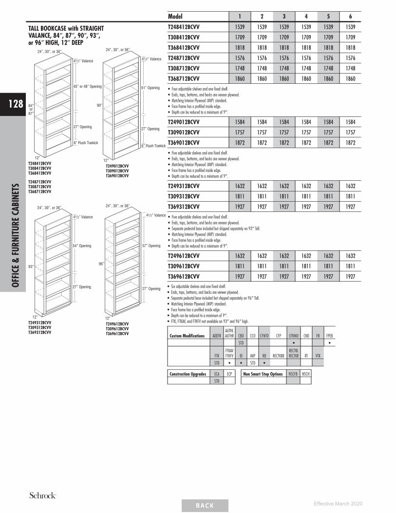
TALL BOOKCASE with STRAIGHTVALANCE, 84″, 87″, 90″, 93″,or 96″ HIGH, 12″ DEEP
41/2” Valance
45” or 48” Opening
27” Opening
6” Flush Toekick
12”
24”, 30”, or 36”
84”or
87”
T248412BCVVT308412BCVVT368412BCVV
T248712BCVVT308712BCVVT368712BCVV
12”
24”, 30”, or 36”
41/2” Valance
51” Opening
27” Opening
90”
6” Flush Toekick
T249012BCVVT309012BCVVT369012BCVV
12”
24”, 30”, or 36”
41/2” Valance
54” Opening
27” Opening
93”
T249312BCVVT309312BCVVT369312BCVV
41/2” Valance
57” Opening
12”
96”
24”, 30”, or 36”
27” Opening
T249612BCVVT309612BCVVT369612BCVV
Model 1 2 3 4 5 6
T248412BCVV 1539 1539 1539 1539 1539 1539
T308412BCVV 1709 1709 1709 1709 1709 1709
T368412BCVV 1818 1818 1818 1818 1818 1818
T248712BCVV 1576 1576 1576 1576 1576 1576
T308712BCVV 1748 1748 1748 1748 1748 1748
T368712BCVV 1860 1860 1860 1860 1860 1860
• Four adjustable shelves and one fixed shelf.• Ends, tops, bottoms, and backs are veneer plywood.• Matching Interior Plywood (MIP) standard.• Face frame has a profiled inside edge.• Depth can be reduced to a minimum of 9″.
T249012BCVV 1584 1584 1584 1584 1584 1584
T309012BCVV 1757 1757 1757 1757 1757 1757
T369012BCVV 1872 1872 1872 1872 1872 1872
• Five adjustable shelves and one fixed shelf.• Ends, tops, bottoms, and backs are veneer plywood.• Matching Interior Plywood (MIP) standard.• Face frame has a profiled inside edge.• Depth can be reduced to a minimum of 9″.
T249312BCVV 1632 1632 1632 1632 1632 1632
T309312BCVV 1811 1811 1811 1811 1811 1811
T369312BCVV 1927 1927 1927 1927 1927 1927
• Five adjustable shelves and one fixed shelf.• Ends, tops, bottoms, and backs are veneer plywood.• Separate pedestal base included but shipped separately on 93″ Tall.• Matching Interior Plywood (MIP) standard.• Face frame has a profiled inside edge.• Depth can be reduced to a minimum of 9″.
T249612BCVV 1632 1632 1632 1632 1632 1632
T309612BCVV 1811 1811 1811 1811 1811 1811
T369612BCVV 1927 1927 1927 1927 1927 1927
• Six adjustable shelves and one fixed shelf.• Ends, tops, bottoms, and backs are veneer plywood.• Separate pedestal base included but shipped separately on 96″ Tall.• Matching Interior Plywood (MIP) standard.• Face frame has a profiled inside edge.• Depth can be reduced to a minimum of 9″.• FTK, FTKAV, and FTKFV not available on 93″ and 96″ high.
Custom Modifications ADDTKAUTHLAUTHR CBO CCO CFNTO CFP CFRMO CND FB FPEB
STD • •
FTKFTKAVFTKFV ID MIP RD RECTKBK
RECTKLRECTKR RT VTK
STD • • STD •
Construction Upgrades ECA ECP
STD
Non Smart Stop Options NSCFB NSCH
OFFI
CE&
FURN
ITUR
ECA
BINE
TS
128
Effective March 2020

DESK DOOR DRAWER BASE,29″ HIGH, 21″ DEEP
21”
29”
DDO122921 L or RDDO152921 L or RDDO182921 L or RDDO212921 L or R
21”
29”
24”, 30”, or 36”
DDO242921DDO302921DDO362921
Model 1 2 3 4 5 6
DDO122921 L or R 467 493 561 588 673 747
DDO152921 L or R 499 524 596 624 716 796
DDO182921 L or R 528 558 636 667 762 846
DDO212921 L or R 564 594 677 710 811 903
DDO242921 621 654 745 781 893 991
DDO302921 728 767 874 915 1047 1163
DDO362921 915 964 1097 1150 1315 1462
FTKAV and FTKFV not available on DDO122921 L or R.
Custom Modifications ADDTKAUTHLAUTHR CBO CCO CFNTO CFP CFRMO CND FB FPEB
• • • • • • • •
FTKFTKAVFTKFV ID MIP RD RECTKBK
RECTKLRECTKR RT VTK
• • • • • • • • •
Construction Upgrades ECA ECP
• •
Non Smart Stop Options NSCFB NSCH
• •
DESK THREE DRAWER BASE,29″ HIGH, 21″ DEEP
21”
29”
3DB122921 578 596 644 663 720 768
3DB152921 621 640 694 714 774 827
3DB182921 669 691 747 770 835 890
3DB212921 713 736 797 819 890 949
3DB242921 765 789 853 879 954 1017
• FTKAV and FTKFV not available on 3DB122921 and 3DB242921.
Custom Modifications ADDTKAUTHLAUTHR CBO CCO CFNTO CFP CFRMO CND FB FPEB
• • • • • •
FTKFTKAVFTKFV ID MIP RD RECTKBK
RECTKLRECTKR RT VTK
• • • • • •
Construction Upgrades ECA ECP
• •
Non Smart Stop Options NSCFB NSCH
•
DESK FILE DRAWER BASE, 29″ HIGH,21″ DEEP
21”
29”
15”, 18”, or 21”
DFD152921 814 850 939 978 1102 1213
DFD182921 853 890 987 1028 1160 1278
DFD212921 904 944 1046 1090 1232 1357
• Door is attached to file drawer.• Includes Filing System Hardware Kit, which accommodates letter and legal filing.• Exterior height of file drawer is 10″.
Custom Modifications ADDTKAUTHLAUTHR CBO CCO CFNTO CFP CFRMO CND FB FPEB
• • • • •
FTKFTKAVFTKFV ID MIP RD RECTKBK
RECTKLRECTKR RT VTK
• • • • • •
Construction Upgrades ECA ECP
• •
Non Smart Stop Options NSCFB NSCH
OFFI
CE&
FURN
ITUR
ECA
BINE
TS
129
Effective March 2020
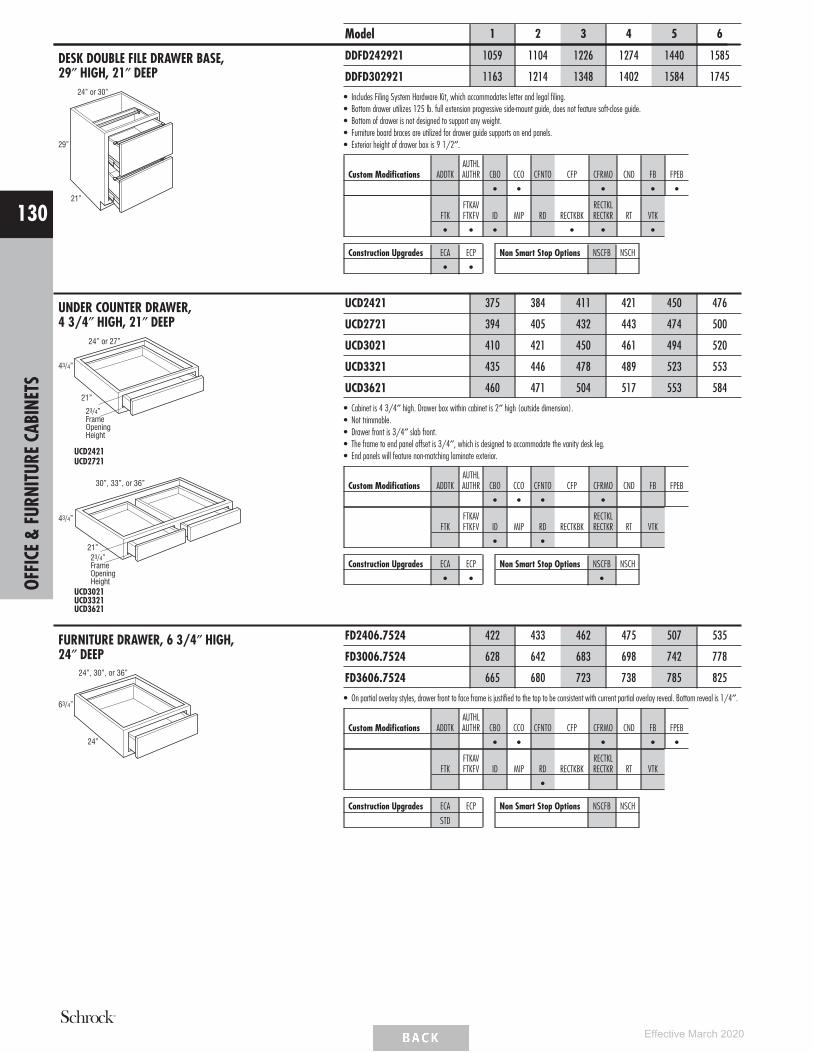
DESK DOUBLE FILE DRAWER BASE,29″ HIGH, 21″ DEEP
21”
29”
24” or 30”
Model 1 2 3 4 5 6
DDFD242921 1059 1104 1226 1274 1440 1585
DDFD302921 1163 1214 1348 1402 1584 1745
• Includes Filing System Hardware Kit, which accommodates letter and legal filing.• Bottom drawer utilizes 125 lb. full extension progressive side-mount guide, does not feature soft-close guide.• Bottom of drawer is not designed to support any weight.• Furniture board braces are utilized for drawer guide supports on end panels.• Exterior height of drawer box is 9 1/2″.
Custom Modifications ADDTKAUTHLAUTHR CBO CCO CFNTO CFP CFRMO CND FB FPEB
• • • • •
FTKFTKAVFTKFV ID MIP RD RECTKBK
RECTKLRECTKR RT VTK
• • • • • •
Construction Upgrades ECA ECP
• •
Non Smart Stop Options NSCFB NSCH
UNDER COUNTER DRAWER,4 3/4″ HIGH, 21″ DEEP
21”
24” or 27”
43/4”
23/4”FrameOpeningHeight
UCD2421UCD2721
21”
30”, 33”, or 36”
43/4”
23/4”FrameOpeningHeight
UCD3021UCD3321UCD3621
UCD2421 375 384 411 421 450 476
UCD2721 394 405 432 443 474 500
UCD3021 410 421 450 461 494 520
UCD3321 435 446 478 489 523 553
UCD3621 460 471 504 517 553 584
• Cabinet is 4 3/4″ high. Drawer box within cabinet is 2″ high (outside dimension).• Not trimmable.• Drawer front is 3/4″ slab front.• The frame to end panel offset is 3/4″, which is designed to accommodate the vanity desk leg.• End panels will feature non-matching laminate exterior.
Custom Modifications ADDTKAUTHLAUTHR CBO CCO CFNTO CFP CFRMO CND FB FPEB
• • • •
FTKFTKAVFTKFV ID MIP RD RECTKBK
RECTKLRECTKR RT VTK
• •
Construction Upgrades ECA ECP
• •
Non Smart Stop Options NSCFB NSCH
•
FURNITURE DRAWER, 6 3/4″ HIGH,24″ DEEP
24”
63/4”
24”, 30”, or 36”
FD2406.7524 422 433 462 475 507 535
FD3006.7524 628 642 683 698 742 778
FD3606.7524 665 680 723 738 785 825
• On partial overlay styles, drawer front to face frame is justified to the top to be consistent with current partial overlay reveal. Bottom reveal is 1/4″.
Custom Modifications ADDTKAUTHLAUTHR CBO CCO CFNTO CFP CFRMO CND FB FPEB
• • • • •
FTKFTKAVFTKFV ID MIP RD RECTKBK
RECTKLRECTKR RT VTK
•
Construction Upgrades ECA ECP
STD
Non Smart Stop Options NSCFB NSCH
OFFI
CE&
FURN
ITUR
ECA
BINE
TS
130
Effective March 2020

FURNITURE DRAWER, 12″ HIGH,24″ DEEP
24”
12”
24”, 30”, or 36”
Model 1 2 3 4 5 6
FD241224 550 562 598 610 649 682
FD301224 748 767 814 832 884 929
FD361224 791 810 860 878 933 980
• Drawer front to face frame reveal is justified to the bottom to be consistent with both full overlay and partial overlay. Top reveal is 1 1/8″ for partialoverlay and 3/8″ for full overlay.
• Exterior height of drawer box is 6 3/8″.
Custom Modifications ADDTKAUTHLAUTHR CBO CCO CFNTO CFP CFRMO CND FB FPEB
• • • • • • •
FTKFTKAVFTKFV ID MIP RD RECTKBK
RECTKLRECTKR RT VTK
•
Construction Upgrades ECA ECP
STD
Non Smart Stop Options NSCFB NSCH
FURNITURE DRAWER WINDOWBENCH, 18″ HIGH, 24″ DEEP
24”
18”
15”, 18”, 21”, 24”,27”, 30”, or 36”
FDWB151824 719 733 767 780 818 850
FDWB181824 730 742 778 792 831 863
FDWB211824 740 755 791 804 844 875
FDWB241824 752 765 801 814 855 888
FDWB271824 772 785 824 837 879 912
FDWB301824 958 976 1023 1041 1091 1133
FDWB361824 1025 1045 1094 1113 1168 1213
• Drawer front to face frame reveal is justified to the bottom to be consistent with both full overlay and partial overlay. Partial overlay top reveal is2 5/8″ and bottom reveal is 1″. Full overlay top reveal is 1 7/8″ and bottom reveal is 1/4″.
• Exterior height of drawer box is 6 3/8″.
Custom Modifications ADDTKAUTHLAUTHR CBO CCO CFNTO CFP CFRMO CND FB FPEB
• • • • • •
FTKFTKAVFTKFV ID MIP RD RECTKBK
RECTKLRECTKR RT VTK
• • • • • •
Construction Upgrades ECA ECP
STD
Non Smart Stop Options NSCFB NSCH OFFI
CE&
FURN
ITUR
ECA
BINE
TS
131
Effective March 2020

VANITY CABINET NOMENCLATURE
Cabinet Type Cabinet DepthCabinet Width Cabinet Height
NOTE:Distance between back of drawer box and back interior ofcabinet is 2 3/4″.All vanity cabinets are predrilled for full depth shelves or roll trays.
TOEKICKS
Vanity Cabinets are shipped with an unfinished toekick.Finished toekicks in matching wood veneer or laminate mustbe ordered separately and field installed.
CUSTOM MODIFICATIONSMod. Description Mod. DescriptionAUTHL Authentic End - LeftAUTHR Authentic End - RightCBO Cabinet Box OnlyCCO Cabinet Case OnlyCFNTO Cabinet Front OnlyCFP Cabinet False PanelCFRMO Cabinet Frame OnlyCMAT CabMat™CND Cabinet with No Door,
with DrawerFB Finished EndsFPEB Furniture Finished
Plywood End Panels
FTK Flush ToekickFTKAV Flush Toekick ArchFTKFV Flush Toekick FurnitureID Increased DepthMIP Matching Interior PlywoodRD Reduced DepthRECTKBK Recessed Toekick BackRECTKL Recessed Toekick LeftRECTKR Recessed Toekick RightRT Installed Roll TrayVTK Void Toekick
CONSTRUCTION UPGRADESMod. DescriptionECA All-plywood ConstructionECP Plywood Ends
NON SMART STOP OPTIONSMod. DescriptionNSCFB Non Soft-close Guides & Furniture Board Drawers and Roll TraysNSCH Non Soft-close Door Hinges
MODIFICATIONS GRID KEY
• AvailableSTD Standard on these cabinets
Smart Solutions™ Organization Cabinet
VANITY SINK BASE with FALSE PANEL,32″ HIGH, 18″ or 21″ DEEP
= False Panel
32”
18” or 21”
24”, 27”, 30”, 33”, or 36”
FP
VSB243218 VSB243221VSB273218 VSB273221VSB303218 VSB303221VSB333218 VSB333221VSB363218 VSB363221
18” or 21”
32”
39”, 42”, 45”, or 48”
FP
FP
VSB393218 VSB393221VSB423218 VSB423221VSB453218 VSB453221VSB483218CS VSB483221CS
32”
54” or 60”
18” or 21”
FP
FP
VSB543218 VSB543221VSB603218 VSB603221
Model 1 2 3 4 5 6
VSB243218 550 579 655 689 789 877
VSB273218 564 593 676 709 810 901
VSB303218 584 616 700 734 840 932
VSB333218 608 641 729 765 876 971
VSB363218 632 668 758 797 911 1011
VSB243221 550 579 655 689 789 877
VSB273221 564 593 676 709 810 901
VSB303221 584 616 700 734 840 932
VSB333221 608 641 729 765 876 971
VSB363221 632 668 758 797 911 1011
VSB393218 659 696 791 831 950 1054
VSB423218 686 723 823 863 988 1097
VSB453218 722 758 864 906 1037 1151
VSB483218CS 791 832 953 1001 1148 1279
VSB393221 659 696 791 831 950 1054
VSB423221 686 723 823 863 988 1097
VSB453221 722 758 864 906 1037 1151
VSB483221CS 791 832 953 1001 1148 1279
VSB543218 898 944 1078 1129 1273 1435
VSB603218 988 1038 1186 1242 1400 1579
VSB543221 898 944 1078 1129 1273 1435
VSB603221 988 1038 1186 1242 1400 1579
• CMAT not available on VSB393221, VSB423221, VSB453221, VSB483221CS, VSB543221, VSB603221, and 18″ deep vanities.• ID not available on VSB483218CS and VSB483221CS.
Custom ModificationsAUTHLAUTHR CBO CCO CFNTO CFP CFRMO CMAT CND FB FPEB
• • • STD • • • • •
FTKFTKAVFTKFV ID MIP RD RECTKBK
RECTKLRECTKR RT VTK
• • • • • • • • •
Construction Upgrades ECA ECP
• •
Non Smart Stop Options NSCFB NSCH
• •
VANI
TYCA
BINE
TS
132
Effective March 2020

VANITY SINK BASE with FALSE PANEL,34 1/2″ HIGH, 21″ DEEP
= False Panel
341/2”
21”
FP
24”, 27”, 30”, 33”, or 36”
VSB243421VSB273421VSB303421VSB333421VSB363421
341/2”
21”
39”, 42”, 45”, or 48”
FPFP
VSB393421VSB423421VSB453421VSB483421CS
341/2”
54” or 60”
FP
FP
21” VSB543421VSB603421
Model 1 2 3 4 5 6
VSB243421 629 660 754 791 903 1006
VSB273421 636 668 759 797 911 1011
VSB303421 657 693 785 825 944 1048
VSB333421 678 715 814 854 977 1087
VSB363421 706 745 849 889 1018 1129
VSB393421 742 782 892 934 1069 1187
VSB423421 778 818 933 978 1120 1244
VSB453421 816 860 980 1025 1176 1305
VSB483421CS 887 937 1071 1123 1289 1436
VSB543421 1006 1057 1207 1264 1426 1607
VSB603421 1107 1163 1328 1391 1568 1768
• CMAT not available on VSB393421, VSB423421, VSB453421, VSB483421CS, VSB543421, and VSB603421.• ID not available on VSB483421CS.
Custom ModificationsAUTHLAUTHR CBO CCO CFNTO CFP CFRMO CMAT CND FB FPEB
• • STD • • • • •
FTKFTKAVFTKFV ID MIP RD RECTKBK
RECTKLRECTKR RT VTK
• • • • • • • • •
Construction Upgrades ECA ECP
• •
Non Smart Stop Options NSCFB NSCH
• •
VANITY BASE, SINGLE DOOR withDRAWER, 32″ HIGH, 21″ DEEP
21”
32”
VB123221 L or R 469 497 564 592 677 752
VB153221 L or R 505 533 607 637 728 809
VB183221 L or R 539 566 647 677 774 862
VB213221 L or R 573 604 688 721 826 917
VB243221 L or R 610 644 733 768 880 975
• FTKAV and FTKFV not available on VB123221 L or R.
Custom ModificationsAUTHLAUTHR CBO CCO CFNTO CFP CFRMO CMAT CND FB FPEB
• • • • • • • • •
FTKFTKAVFTKFV ID MIP RD RECTKBK
RECTKLRECTKR RT VTK
• • • • • • • • •
Construction Upgrades ECA ECP
• •
Non Smart Stop Options NSCFB NSCH
• •
VANITY BASE, SINGLE DOOR withDRAWER, 34 1/2″ HIGH, 21″ DEEP
21”
341/2”
VB123421 L or R 500 525 598 626 718 799
VB153421 L or R 538 565 643 674 771 857
VB183421 L or R 570 600 684 719 822 912
VB213421 L or R 608 641 729 765 876 971
VB243421 L or R 648 680 776 814 932 1036
• FTKAV and FTKFV not available on VB123421 L or R.
Custom ModificationsAUTHLAUTHR CBO CCO CFNTO CFP CFRMO CMAT CND FB FPEB
• • • • • • • • •
FTKFTKAVFTKFV ID MIP RD RECTKBK
RECTKLRECTKR RT VTK
• • • • • • • • •
Construction Upgrades ECA ECP
• •
Non Smart Stop Options NSCFB NSCH
• •
VANI
TYCA
BINE
TS
133
Effective March 2020
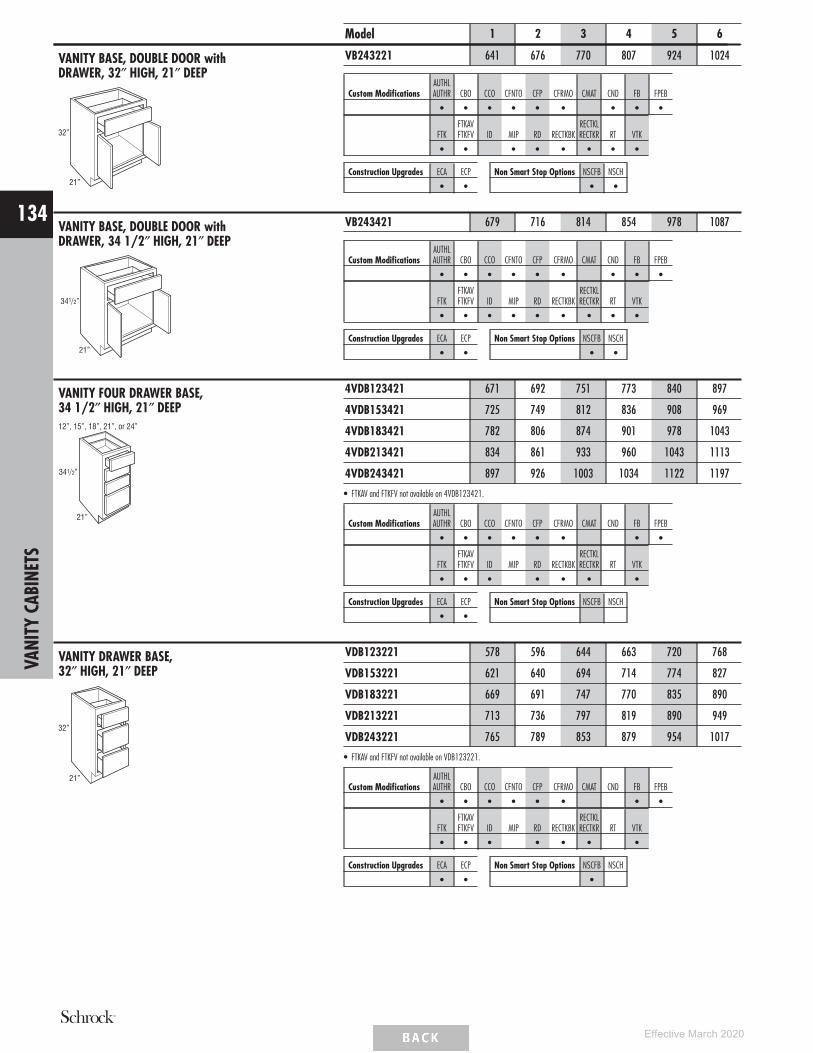
VANITY BASE, DOUBLE DOOR withDRAWER, 32″ HIGH, 21″ DEEP
21”
32”
Model 1 2 3 4 5 6
VB243221 641 676 770 807 924 1024
Custom ModificationsAUTHLAUTHR CBO CCO CFNTO CFP CFRMO CMAT CND FB FPEB
• • • • • • • • •
FTKFTKAVFTKFV ID MIP RD RECTKBK
RECTKLRECTKR RT VTK
• • • • • • • •
Construction Upgrades ECA ECP
• •
Non Smart Stop Options NSCFB NSCH
• •
VANITY BASE, DOUBLE DOOR withDRAWER, 34 1/2″ HIGH, 21″ DEEP
21”
341/2”
VB243421 679 716 814 854 978 1087
Custom ModificationsAUTHLAUTHR CBO CCO CFNTO CFP CFRMO CMAT CND FB FPEB
• • • • • • • • •
FTKFTKAVFTKFV ID MIP RD RECTKBK
RECTKLRECTKR RT VTK
• • • • • • • • •
Construction Upgrades ECA ECP
• •
Non Smart Stop Options NSCFB NSCH
• •
VANITY FOUR DRAWER BASE,34 1/2″ HIGH, 21″ DEEP
341/2”
21”
12”, 15”, 18”, 21”, or 24”
4VDB123421 671 692 751 773 840 897
4VDB153421 725 749 812 836 908 969
4VDB183421 782 806 874 901 978 1043
4VDB213421 834 861 933 960 1043 1113
4VDB243421 897 926 1003 1034 1122 1197
• FTKAV and FTKFV not available on 4VDB123421.
Custom ModificationsAUTHLAUTHR CBO CCO CFNTO CFP CFRMO CMAT CND FB FPEB
• • • • • • • •
FTKFTKAVFTKFV ID MIP RD RECTKBK
RECTKLRECTKR RT VTK
• • • • • • •
Construction Upgrades ECA ECP
• •
Non Smart Stop Options NSCFB NSCH
VANITY DRAWER BASE,32″ HIGH, 21″ DEEP
21”
32”
VDB123221 578 596 644 663 720 768
VDB153221 621 640 694 714 774 827
VDB183221 669 691 747 770 835 890
VDB213221 713 736 797 819 890 949
VDB243221 765 789 853 879 954 1017
• FTKAV and FTKFV not available on VDB123221.
Custom ModificationsAUTHLAUTHR CBO CCO CFNTO CFP CFRMO CMAT CND FB FPEB
• • • • • • • •
FTKFTKAVFTKFV ID MIP RD RECTKBK
RECTKLRECTKR RT VTK
• • • • • • •
Construction Upgrades ECA ECP
• •
Non Smart Stop Options NSCFB NSCH
•
VANI
TYCA
BINE
TS
134
Effective March 2020

VANITY DRAWER BASE,34 1/2″ HIGH, 21″ DEEP
21”
341/2”
Model 1 2 3 4 5 6
VDB123421 634 655 708 729 790 843
VDB153421 679 701 760 781 848 905
VDB183421 732 755 816 841 912 973
VDB213421 780 805 873 898 974 1039
VDB243421 836 863 934 962 1044 1113
• FTKAV and FTKFV not available on VDB123421.
Custom ModificationsAUTHLAUTHR CBO CCO CFNTO CFP CFRMO CMAT CND FB FPEB
• • • • • • • •
FTKFTKAVFTKFV ID MIP RD RECTKBK
RECTKLRECTKR RT VTK
• • • • • • •
Construction Upgrades ECA ECP
• •
Non Smart Stop Options NSCFB NSCH
•
VANITY PULL-OUT,34 1/2″ HIGH, 21″ DEEP
21”
341/2”
9”
InteriorWidth33/4”
Pull-outInteriorDepth19”
VP93421 1184 1234 1376 1434 1608 1761
• Natural Finish with Smart Stop wood pull-out with adjustable shelves and chrome rail sides.• Pull-out is 19 9/16″ deep.
Custom ModificationsAUTHLAUTHR CBO CCO CFNTO CFP CFRMO CMAT CND FB FPEB
• • • • • •
FTKFTKAVFTKFV ID MIP RD RECTKBK
RECTKLRECTKR RT VTK
• •
Construction Upgrades ECA ECP
• •
Non Smart Stop Options NSCFB NSCH
VANI
TYCA
BINE
TS
135
Effective March 2020

VANITY SINK DRAWER BASE,32″ HIGH, 21″ DEEP
32”
36”
21”
FP
21”
= False Panel
2VSD363221
21”
32”
42”, 45”, or 48”
FP
21” or 24”
2VSD4232212VSD453221
2VSD483221CS
27”12” or
15”
21”
32”
FP
54” or 60” 12” or15”
2VSD543221FP2VSD603221FP
Model 1 2 3 4 5 6
2VSD363221 806 850 968 1015 1160 1291
2VSD423221 930 978 1114 1167 1335 1483
2VSD453221 966 1015 1158 1213 1388 1542
2VSD483221CS 975 1026 1176 1232 1415 1574
2VSD543221FP 1077 1132 1293 1355 1549 1720
2VSD603221FP 1143 1201 1370 1436 1643 1824
• 2VSD42 and 2VSD48 cabinets have 21″ space between drawers.• 2VSD45 cabinets have 24″ space between drawers.• CMAT not available on 2VSD423221, 2VSD453221, and 2VSD483221CS.• ID not available on 2VSD483221CS.• RT not available on 2VSD543221FP and 2VSD603221FP.
Custom ModificationsAUTHLAUTHR CBO CCO CFNTO CFP CFRMO CMAT CND FB FPEB
• • • • • • • • • •
FTKFTKAVFTKFV ID MIP RD RECTKBK
RECTKLRECTKR RT VTK
• • • • • • • • •
Construction Upgrades ECA ECP
• •
Non Smart Stop Options NSCFB NSCH
• •
VANI
TYCA
BINE
TS
136
Effective March 2020

VANITY SINK DRAWER BASE,34 1/2″ HIGH, 21″ DEEP
36”
21”
FP
21”
341/2”
= False Panel2VSD363421
21”
341/2”
42”, 45”, or 48”
FP
21” or 24”
2VSD4234212VSD453421
2VSD483421CS
27”
341/2”
54” or 60”
FP
21”
12” or15”
12” or15”
2VSD543421FP2VSD603421FP
Model 1 2 3 4 5 6
2VSD363421 905 952 1087 1139 1302 1445
2VSD423421 1040 1093 1247 1306 1495 1661
2VSD453421 1082 1138 1296 1359 1555 1727
2VSD483421CS 1096 1154 1319 1384 1588 1767
2VSD543421FP 1207 1269 1447 1518 1736 1929
2VSD603421FP 1279 1346 1533 1608 1841 2043
• 2VSD42 and 2VSD48 cabinets have 21″ space between drawers.• 2VSD45 cabinets have 24″ space between drawers.• CMAT not available on 2VSD423421, 2VSD453421, and 2VSD483421CS.• ID not available on 2VSD483421CS.• RT not available on 2VSD543421FP and 2VSD603421FP.
Custom ModificationsAUTHLAUTHR CBO CCO CFNTO CFP CFRMO CMAT CND FB FPEB
• • • • • • • • • •
FTKFTKAVFTKFV ID MIP RD RECTKBK
RECTKLRECTKR RT VTK
• • • • • • • • •
Construction Upgrades ECA ECP
• •
Non Smart Stop Options NSCFB NSCH
• •
VANI
TYCA
BINE
TS
137
Effective March 2020

VANITY SINK DRAWER BASE withFALSE PANELS, 32″ HIGH, 21″ DEEP
32”
24” or 30”
9”FrameOpening
FP
21”
= False Panel
VSD243221FP DL or DRVSD303221FP DL or DR
9”FrameOpening
32”
36”
FP
21”
VSD363221FP DL or DR
9”FrameOpening
42” or 48”
32”
FP
21”
VSD423221FP DL or DRVSD483221FP DL or DR
32”
60”
15”FrameOpening
FP
FP
FP
21”
VSD603221FP
Model 1 2 3 4 5 6
VSD243221FP DL or DR 765 795 878 911 1008 1091
VSD303221FP DL or DR 825 857 946 981 1086 1177
VSD363221FP DL or DR 907 943 1041 1079 1195 1294
VSD423221FP DL or DR 1006 1045 1154 1196 1324 1435
VSD483221FP DL or DR 1051 1092 1207 1251 1384 1501
VSD603221FP 1148 1194 1319 1367 1512 1639
• DL or DR indicates drawer location (DL shown).• CFP is standard on VSD243221FP DL or DR, VSD303221FP DL or DR, VSD363221FP DL or DR, and VSD603221FP. CFP is available on
VSD423221FP DL or DR and VSD483221FP DL or DR.• CMAT not available on VSD243221FP DL or DR, VSD303221FP DL or DR, and VSD603221FP.• CND not available on VSD423221FP DL or DR, VSD483221FP DL or DR, and VSD603221FP.
Custom ModificationsAUTHLAUTHR CBO CCO CFNTO CFP CFRMO CMAT CND FB FPEB
• • • • STD • • • • •
FTKFTKAVFTKFV ID MIP RD RECTKBK
RECTKLRECTKR RT VTK
• • • • • • •
Construction Upgrades ECA ECP
• •
Non Smart Stop Options NSCFB NSCH
• •
VANI
TYCA
BINE
TS
138
Effective March 2020

VANITY SINK DRAWER BASE withFALSE PANEL, 34 1/2″ HIGH,21″ DEEP
24” or 30”
FP
9”FrameOpening
21”
341/2”
= False Panel
VSD243421FP DL or DRVSD303421FP DL or DR
9”FrameOpening
21”
36”
341/2”
FP
VSD363421FP DL or DR
9”FrameOpening
21”
341/2”
42” or 48”
FP
VSD423421FP DL or DRVSD483421FP DL or DR
21”
341/2”
60”
15”FrameOpening
FP
FP
FP
VSD603421FP
Model 1 2 3 4 5 6
VSD243421FP DL or DR 854 889 981 1017 1126 1221
VSD303421FP DL or DR 924 960 1060 1099 1217 1319
VSD363421FP DL or DR 1013 1054 1164 1207 1336 1446
VSD423421FP DL or DR 1123 1167 1289 1337 1480 1603
VSD483421FP DL or DR 1176 1223 1350 1400 1549 1678
VSD603421FP 1285 1336 1476 1530 1694 1835
• DL or DR indicates drawer location (DL shown).• CFP is standard on VSD243421FP DL or DR, VSD303421FP DL or DR, VSD363421FP DL or DR, and VSD603421FP. CFP is available on
VSD423421FP DL or DR and VSD483421FP DL or DR.• CMAT not available on VSD243421FP DL or DR, VSD303421FP DL or DR, and VSD603421FP.• CND not available on VSD423421FP DL or DR, VSD483421FP DL or DR, and VSD603421FP.
Custom ModificationsAUTHLAUTHR CBO CCO CFNTO CFP CFRMO CMAT CND FB FPEB
• • • • STD • • • • •
FTKFTKAVFTKFV ID MIP RD RECTKBK
RECTKLRECTKR RT VTK
• • • • • • •
Construction Upgrades ECA ECP
• •
Non Smart Stop Options NSCFB NSCH
• •
VANI
TYCA
BINE
TS
139
Effective March 2020

VANITY SINK THREE DRAWER BASE,32″ HIGH, 21″ DEEP
21”
32”
54” or 60”
21”
21”
FP
FP
9” or 15”Frame Opening = False Panel
Model 1 2 3 4 5 6
VS3D543221 1424 1481 1636 1696 1877 2033
VS3D603221 1424 1481 1636 1696 1877 2033
Custom ModificationsAUTHLAUTHR CBO CCO CFNTO CFP CFRMO CMAT CND FB FPEB
• • • • • • • • •
FTKFTKAVFTKFV ID MIP RD RECTKBK
RECTKLRECTKR RT VTK
• • • • • • •
Construction Upgrades ECA ECP
• •
Non Smart Stop Options NSCFB NSCH
• •
VANITY SINK THREE DRAWER BASE,34 1/2″ HIGH, 21″ DEEP
54” or 60”
9” or 15”Frame Opening
21”
341/2”
21”
21”
FP
FP
= False Panel
VS3D543421 1596 1658 1832 1898 2102 2277
VS3D603421 1596 1658 1832 1898 2102 2277
Custom ModificationsAUTHLAUTHR CBO CCO CFNTO CFP CFRMO CMAT CND FB FPEB
• • • • • • • • •
FTKFTKAVFTKFV ID MIP RD RECTKBK
RECTKLRECTKR RT VTK
• • • • • • •
Construction Upgrades ECA ECP
• •
Non Smart Stop Options NSCFB NSCH
• •
VANITY SINK DRAWER BASE withSIX DRAWERS & FALSE PANEL,32″ HIGH, 21″ DEEP
9”FrameOpening
9”FrameOpening
21”9”
9”
21”
32”
FP
42”
6VSD423221FP L or R
9”FrameOpening
48”
9”FrameOpening
27”9”
9”
32”
FP
21”
6VSD483221FP
32”
54”, 57”, or 60”
27” or 30”
12” or 15”FrameOpening
12” or 15”FrameOpening
FP
21”
6VSD543221FP6VSD573221FP6VSD603221FP
6VSD423221FP L or R 1140 1183 1277 1327 1327 2038
6VSD483221FP 1277 1327 1465 1520 1682 1822
6VSD543221FP 1392 1447 1597 1657 1833 1986
6VSD573221FP 1462 1519 1677 1740 1925 2085
6VSD603221FP 1514 1575 1738 1803 1996 2162
• 6VSD423221FP L or R drawer stack is 9″ wide.• 6VSD483221FP drawer stack is 12″ wide.• 6VSD543221FP drawer stack is 15″ wide.• 6VSD573221FP drawer stack is 15″ wide and sink clearance opening is 30" wide.• 6VSD603221FP drawer stack is 18″ wide.• CMAT not available on 6VSD423221FP.
Custom ModificationsAUTHLAUTHR CBO CCO CFNTO CFP CFRMO CMAT CND FB FPEB
• • • • • • • • • •
FTKFTKAVFTKFV ID MIP RD RECTKBK
RECTKLRECTKR RT VTK
• • • • • • •
Construction Upgrades ECA ECP
• •
Non Smart Stop Options NSCFB NSCH
• •
VANI
TYCA
BINE
TS
140
Effective March 2020

VANITY SINK DRAWER BASE withSIX DRAWERS & FALSE PANEL,34 1/2″ HIGH, 21″ DEEP
9”FrameOpening
9”FrameOpening
21”
341/2”
9”
9”
FP
21”
42”
6VSD423421FP L or R
9”FrameOpening
21”
48”
9”FrameOpening
27”
341/2”
9”
9”
FP
6VSD483421FP
21”
54”, 57”, or 60”
27” or 30”
341/2”
12” or 15”FrameOpening
12” or 15”FrameOpening
FP
6VSD543421FP6VSD573421FP6VSD603421FP
Model 1 2 3 4 5 6
6VSD423421FP L or R 1429 1486 1640 1701 1883 2039
6VSD483421FP 1429 1486 1640 1701 1883 2039
6VSD543421FP 1559 1621 1789 1856 2053 2224
6VSD573421FP 1637 1701 1878 1949 2156 2335
6VSD603421FP 1697 1765 1949 2020 2236 2423
• 6VSD423421FP L or R drawer stack is 9″ wide.• 6VSD483421FP drawer stack is 12″ wide.• 6VSD543421FP drawer stack is 15″ wide.• 6VSD573421FP drawer stack is 15″ wide and sink clearance opening is 30" wide.• 6VSD603421FP drawer stack is 18″ wide.• CMAT not available on 6VSD423421FP.
Custom ModificationsAUTHLAUTHR CBO CCO CFNTO CFP CFRMO CMAT CND FB FPEB
• • • • • • • • • •
FTKFTKAVFTKFV ID MIP RD RECTKBK
RECTKLRECTKR RT VTK
• • • • • • •
Construction Upgrades ECA ECP
• •
Non Smart Stop Options NSCFB NSCH
• •
UNDER COUNTER DRAWER,4 3/4″ HIGH, 21″ DEEP
21”
24” or 27”
43/4”
23/4”FrameOpeningHeight
UCD2421UCD2721
21”
30”, 33”, or 36”
43/4”
23/4”FrameOpeningHeight
UCD3021UCD3321UCD3621
UCD2421 375 384 411 421 450 476
UCD2721 394 405 432 443 474 500
UCD3021 410 421 450 461 494 520
UCD3321 435 446 478 489 523 553
UCD3621 460 471 504 517 553 584
• Cabinet is 4 3/4″ high. Drawer box within cabinet is 2″ high (outside dimension).• Not trimmable.• Drawer front is 3/4″ slab front.• The frame to end panel offset is 3/4″, which is designed to accommodate the vanity desk leg.• End panels will feature non-matching laminate exterior.
Custom ModificationsAUTHLAUTHR CBO CCO CFNTO CFP CFRMO CMAT CND FB FPEB
• • • •
FTKFTKAVFTKFV ID MIP RD RECTKBK
RECTKLRECTKR RT VTK
• •
Construction Upgrades ECA ECP
• •
Non Smart Stop Options NSCFB NSCH
•
VANI
TYCA
BINE
TS
141
Effective March 2020

LINEN CLOSET
21”
84”
18”
461/2”FrameOpeningHeight
27”FrameOpeningHeight
Model 1 2 3 4 5 6
LC188421 L or R 1674 1732 1891 1957 2172 2365
• Upper section features a 5″ deep chrome door rack.• 15″ deep adjustable shelves indicated by light dotted lines are included; packaged separately.• Designed to be used with 34 1/2″ high vanities. Bottom door aligns with top of door/drawer front.
Custom ModificationsAUTHLAUTHR CBO CCO CFNTO CFP CFRMO CMAT CND FB FPEB
• • • • • •
FTKFTKAVFTKFV ID MIP RD RECTKBK
RECTKLRECTKR RT VTK
• • • • • •
Construction Upgrades ECA ECP
• •
Non Smart Stop Options NSCFB NSCH
•
LINEN CLOSET with REMOVABLEHAMPER
461/2”FrameOpeningHeight
27”FrameOpeningHeight
21”
84”
18”
LCRH188421 L or R 2011 2069 2227 2295 2510 2702
• Hamper size is 19 3/8″ high x 14 3/4″ wide x 18″ deep.• Upper section features a 5″ deep chrome door rack.• 15″ deep adjustable shelves indicated by light dotted lines are included; packaged separately.• Includes full extension removable chrome pull-out hamper with removable cloth liner.• Designed to be used with 34 1/2″ high vanities. Bottom door aligns with top of door/drawer front.
Custom ModificationsAUTHLAUTHR CBO CCO CFNTO CFP CFRMO CMAT CND FB FPEB
• • • • • •
FTKFTKAVFTKFV ID MIP RD RECTKBK
RECTKLRECTKR RT VTK
• • • • •
Construction Upgrades ECA ECP
• •
Non Smart Stop Options NSCFB NSCH
•
VANITY UTILITY,84″ TALL, 21″ DEEP
84”
21”
18”
241/2”FrameOpeningHeight
241/2”FrameOpeningHeight
201/2”FrameOpeningHeight
VU188421 L or R 1017 1070 1221 1279 1464 1626
• Lower door section is drilled to accept adjustable shelf.• Shelves indicated by light dotted lines are included; packaged separately.• Shelves indicated by solid lines are fixed.• Designed to be used with 32″ tall vanities. Linen Closet (LC/LCRH) cabinets or kitchen utilities should be used for 34 1/2″ vanity applications.
Custom ModificationsAUTHLAUTHR CBO CCO CFNTO CFP CFRMO CMAT CND FB FPEB
• • • • • •
FTKFTKAVFTKFV ID MIP RD RECTKBK
RECTKLRECTKR RT VTK
• • • • • • • •
Construction Upgrades ECA ECP
• •
Non Smart Stop Options NSCFB NSCH
•
VANITY WALL TOWEL BAR
36”
9”251/2”
9”
251/2”
InteriorDepth 8”
VWTB24 770 794 863 890 972 1047
• Includes 2 adjustable interior shelves, 1 fixed shelf, and towel rack underneath.• Cabinet has butt doors, no center stile.• Cabinet features factory applied 3/4″ matching veneer over furniture board core end panels. Total cabinet width is 25 1/2″.• Interior cabinet case has plywood end panels.• When ordered in ECA, back, top, bottom and adjustable shelves are plywood.
Custom ModificationsAUTHLAUTHR CBO CCO CFNTO CFP CFRMO CMAT CND FB FPEB
• • • STD
FTKFTKAVFTKFV ID MIP RD RECTKBK
RECTKLRECTKR RT VTK
•
Construction Upgrades ECA ECP
• STD
Non Smart Stop Options NSCFB NSCH
•
VANI
TYCA
BINE
TS
142
Effective March 2020

VANITY WALL, 30″ HIGH, 6″ DEEP
30”
6”
24”
Model 1 2 3 4 5 6
W24306 500 528 600 630 721 801
Custom ModificationsAUTHLAUTHR CBO CCO CFNTO CFP CFRMO CMAT CND FB FPEB
• • • • • •
FTKFTKAVFTKFV ID MIP RD RECTKBK
RECTKLRECTKR RT VTK
•
Construction Upgrades ECA ECP
• •
Non Smart Stop Options NSCFB NSCH
•
VANITY WALL MIRROR CABINET,30″ HIGH, 4 9/16″ DEEP
30”
49/16”
24”
VWM2430 L or R 807 832 899 927 1009 1083
• Standard with CG doors and installed mirror glass.• Unit intended to be surface mounted. Features standard 1/4″ face frame reveal on ends.• Adjustable shelves.• Not available in Rivali.
Custom ModificationsAUTHLAUTHR CBO CCO CFNTO CFP CFRMO CMAT CND FB FPEB
• • • • • •
FTKFTKAVFTKFV ID MIP RD RECTKBK
RECTKLRECTKR RT VTK
•
Construction Upgrades ECA ECP
• •
Non Smart Stop Options NSCFB NSCH
•
VANITY MIRROR211/4”, 271/4”,
or 331/4”
23/8”
18”, 24”,
or 30”35”
3/4”
191/2”, 251/2”,or 311/2”
11/2”
23/8”
11/2”
35”
3/4”
25/8”
mirror frame profile
1/2”
OverallDimensions
Mirror -VisibleDimensions
Model Width Height Width HeightVM2135 21 1/4″ 35″ 12 15/16″ 26 15/16″VM2735 27 1/4″ 35″ 18 15/16″ 26 15/16″VM3335 33 1/4″ 35″ 24 15/16″ 26 15/16″
VM2135 781 781 781 781 781 781
VM2735 851 851 851 851 851 851
VM3335 924 924 924 924 924 924
• Moulding included on vanity mirrors is not a standard moulding. SWLCRM8 is similar.• Mirror glass is beveled.• Includes two installed metal hanging hooks on back.
MODIFICATIONS
No modifications available forthese products.
Species AvailabilityPainted
HardwoodStained
Hardwood• •
SINGLE DOOR MEDICINE CABINET
49/16”
267/8”
153/4”
Cabinet Dimensions Cut-out DimensionsModel Width Height Depth Width Height DepthMC16 15 3/4″ 26 7/8″ 4 9/16″ 14 7/16″ 25 5/8″ 4″
MC16 750 750 750 750 750 750
• Unit can be surface mounted or recessed.• Door of cabinet is glass mirror, 12 5/8″ wide x 23 1/2″ high.• Matching cabinet doors not available.• Cabinet has wood frame.• Natural Maple laminate interior.• Face frame has a profiled inside and outside edge.
Custom ModificationsAUTHLAUTHR CBO CCO CFNTO CFP CFRMO CMAT CND FB FPEB
• • • STD
FTKFTKAVFTKFV ID MIP RD RECTKBK
RECTKLRECTKR RT VTK
•
Construction Upgrades ECA ECP
STD
Non Smart Stop Options NSCFB NSCH
VANI
TYCA
BINE
TS
143
Effective March 2020

TRI-VIEW MEDICINE CABINET
267/8”
49/16”
Cabinet Dimensions Cut-out DimensionsModel Width Height Depth Width Height DepthTV30 30″ 26 7/8″ 4 9/16″ 28 11/16″ 25 5/8″ 4″TV36 36″ 26 7/8″ 4 9/16″ 34 11/16″ 25 5/8″ 4″TV48 48″ 26 7/8″ 4 9/16″ 46 11/16″ 25 5/8″ 4″
Model 1 2 3 4 5 6
TV30 1125 1125 1125 1125 1125 1125
TV36 1223 1223 1223 1223 1223 1223
TV48 1535 1535 1535 1535 1535 1535
• Cabinet has wood frame.• Door of cabinet is glass mirror.• Unit can be surface mounted or recessed.• Natural Maple laminate interior.• Face frame has a profiled inside and outside edge.
Custom ModificationsAUTHLAUTHR CBO CCO CFNTO CFP CFRMO CMAT CND FB FPEB
• • • STD
FTKFTKAVFTKFV ID MIP RD RECTKBK
RECTKLRECTKR RT VTK
•
Construction Upgrades ECA ECP
STD
Non Smart Stop Options NSCFB NSCH
VANI
TYCA
BINE
TS
144
Effective March 2020

SPECIES AVAILABILITY
Species Availability charts list the availability of each product code by species and any substitutionsthat are made. Exceptions within a section are noted below the species availability chart.
For panels with doors and/or fillers attached, species availability is shown for the panel and filleronly.
For Species Availability, look for this chart throughout.
Species AvailabilityPainted
HardwoodStained
Hardwood• •
DESCRIPTION MODEL PRICEFILLERS
3″ WIDE FILLERS3”
3/4”
30”33”36”39”42”
791/2”821/2”851/2”881/2”911/2”
or96”
F3
F330 55
F333 61
F336 62
F339 65
F342 69
TF384 115
TF387 136
TF390 141
TF393 160
TF396 175
TF396FH 217
• 3/4″ thick.• Finished on front and all edges (backs are not finished).Species Availability
PaintedHardwood
StainedHardwood
• •
3″ WIDE CORNER FILLER3”
30”
3”
3/4”
CF3
CF330 98
• 3/4″ thick.• Finished on front and all edges (backs are not finished).Species Availability
PaintedHardwood
StainedHardwood
• •
6″ WIDE FILLERS6”
3/4”
30”33”36”39”42”
791/2”821/2”851/2”881/2”911/2”
or96”
F6
F630 84
F633 101
F636 105
F639 113
F642 124
TF684 202
TF687 240
TF690 249
TF693 273
TF696 298
TF696FH 374
• 3/4″ thick.• Finished on front and all edges (backs are not finished).Species Availability
PaintedHardwood
StainedHardwood
• •
DESCRIPTION MODEL PRICE
OVERLAY FILLER,2 1/2″ WIDE
21/2”
3/4”
Model
PartialOverlayHeight
FullOverlayHeight
OL312 – 11 1/2″OL315 – 14 1/2″OL318 – 17 1/2″OL321 – 20 1/2″OL324 – 23 1/2″OL327 – 26 1/2″OL330 28″ 29 1/2″OL333 31″ 32 1/2″OL336 34″ 35 1/2″OL339 37″ 38 1/2″OL342 40″ 41 1/2″OL384 – 79″OL387 – 82″OL390 – 85″OL393 – 88″OL396 – 91″
OL312 51
OL315 53
OL318 54
OL321 57
OL324 58
OL327 60
OL330 69
OL333 77
OL336 79
OL339 83
OL342 85
OL384 141
OL387 154
OL390 159
OL393 167
OL396 177
• 2 1/2″ wide overlay fillers can be applied to WallMessage Centers to create custom finished look.
• Finished on front and all edges (backs are not finished).Species Availability
PaintedHardwood
StainedHardwood
• •
OVERLAY FILLER,5 1/2″ WIDE
51/2”
3/4”
Model
PartialOverlayHeight
FullOverlayHeight
OL630 28″ 29 1/2″OL633 31″ 32 1/2″OL636 34″ 35 1/2″OL639 37″ 38 1/2″OL642 40″ 41 1/2″OL684 – 79″OL687 – 82″OL690 – 85″OL693 – 88″OL696 – 91″
OL630 97
OL633 123
OL636 128
OL639 135
OL642 141
OL684 236
OL687 267
OL690 275
OL693 284
OL696 291
• Finished on front and all edges (backs are not finished).Species Availability
PaintedHardwood
StainedHardwood
• •
FILL
ERS
145
Effective March 2020
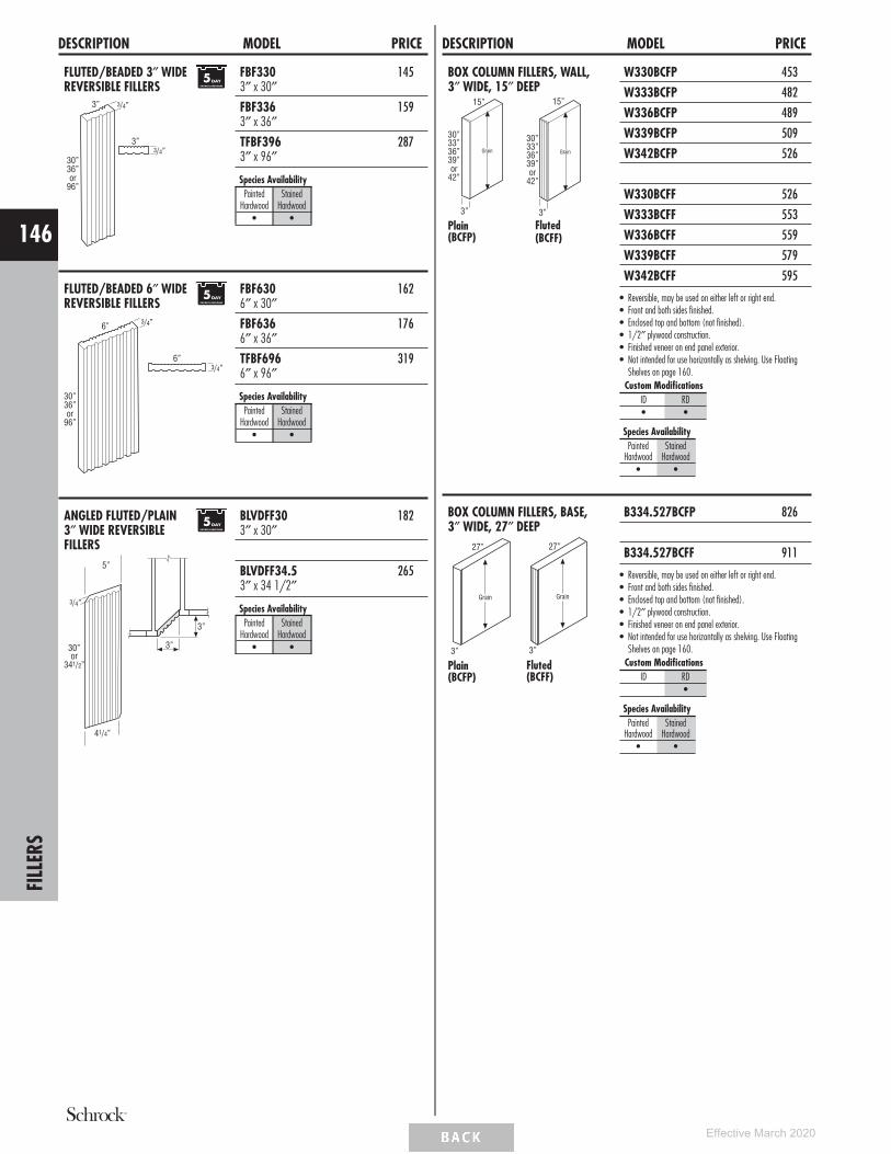
DESCRIPTION MODEL PRICE
FLUTED/BEADED 3″ WIDEREVERSIBLE FILLERS
3” 3/4”
30”36”or
96”
3”3/4”
FBF330 1453″ x 30″FBF336 1593″ x 36″TFBF396 2873″ x 96″
Species AvailabilityPainted
HardwoodStained
Hardwood• •
FLUTED/BEADED 6″ WIDEREVERSIBLE FILLERS
3/4”
30”36”or
96”
6”3/4”
6”
FBF630 1626″ x 30″FBF636 1766″ x 36″TFBF696 3196″ x 96″
Species AvailabilityPainted
HardwoodStained
Hardwood• •
ANGLED FLUTED/PLAIN3″ WIDE REVERSIBLEFILLERS
30”
341/2”or
5”
3/4”
41/4”
3”
3”
BLVDFF30 1823″ x 30″
BLVDFF34.5 2653″ x 34 1/2″
Species AvailabilityPainted
HardwoodStained
Hardwood• •
DESCRIPTION MODEL PRICE
BOX COLUMN FILLERS, WALL,3″ WIDE, 15″ DEEP
3”
15”
Grain33”30”
36”39”or
42”
Plain(BCFP)
15”
Grain
3”
33”30”
36”39”or
42”
Fluted(BCFF)
W330BCFP 453
W333BCFP 482
W336BCFP 489
W339BCFP 509
W342BCFP 526
W330BCFF 526
W333BCFF 553
W336BCFF 559
W339BCFF 579
W342BCFF 595
• Reversible, may be used on either left or right end.• Front and both sides finished.• Enclosed top and bottom (not finished).• 1/2″ plywood construction.• Finished veneer on end panel exterior.• Not intended for use horizontally as shelving. Use Floating
Shelves on page 160.Custom Modifications
ID RD• •
Species AvailabilityPainted
HardwoodStained
Hardwood• •
BOX COLUMN FILLERS, BASE,3″ WIDE, 27″ DEEP
3”
27”
Grain
Plain(BCFP)
3”
27”
Grain
Fluted(BCFF)
B334.527BCFP 826
B334.527BCFF 911
• Reversible, may be used on either left or right end.• Front and both sides finished.• Enclosed top and bottom (not finished).• 1/2″ plywood construction.• Finished veneer on end panel exterior.• Not intended for use horizontally as shelving. Use Floating
Shelves on page 160.Custom Modifications
ID RD•
Species AvailabilityPainted
HardwoodStained
Hardwood• •
FILL
ERS
146
Effective March 2020

DESCRIPTION MODEL PRICE
BOX COLUMN FILLERS, TALL,3″ WIDE, 15″ or 27″ DEEP
15” or 27”
3”
Grain84”87”90”93”or
96”
Plain(BCFP)
15” or 27”
3”
Grain84”87”90”93”or
96”
Fluted(BCFF)
T38415BCFP (15″ Deep) 1065
T38715BCFP (15″ Deep) 1075
T39015BCFP (15″ Deep) 1078
T39315BCFP (15″ Deep) 1099
T39615BCFP (15″ Deep) 1099
T38427BCFP (27″ Deep) 1633
T38727BCFP (27″ Deep) 1654
T39027BCFP (27″ Deep) 1658
T39327BCFP (27″ Deep) 1677
T39627BCFP (27″ Deep) 1677
T38415BCFF (15″ Deep) 1155
T38715BCFF (15″ Deep) 1177
T39015BCFF (15″ Deep) 1183
T39315BCFF (15″ Deep) 1210
T39615BCFF (15″ Deep) 1210
T38427BCFF (27″ Deep) 1717
T38727BCFF (27″ Deep) 1743
T39027BCFF (27″ Deep) 1750
T39327BCFF (27″ Deep) 1789
T39627BCFF (27″ Deep) 1789
• Reversible, may be used on either left or right end.• Front and both sides finished.• Enclosed top and bottom (not finished).• 1/2″ plywood construction.• Finished veneer on end panel exterior.• Not intended for use horizontally as shelving. Use Floating
Shelves on page 160.Custom Modifications
ID RD•* •
*ID not available on 27″deep.
Species AvailabilityPainted
HardwoodStained
Hardwood• •
DESCRIPTION MODEL PRICEPANELS & SKINS
END PANEL SKINS, WALL
30”33”36”39”or
42”
111/4”
Grain
1/4″ Finished
WEPS30WD 87
WEPS33WD 97
WEPS36WD 107
WEPS39WD 118
WEPS42WD 126
1/4″ Laminate
WEPS30LAM14♦ 44
WEPS33LAM14♦ 53
WEPS36LAM14♦ 55
WEPS39LAM14♦ 62
WEPS42LAM14♦ 67
• Stains: 1/4″ thick veneered furniture board.• Paints: 1/4″ thick veneered or solid furniture board.• 1/4″ thick laminated furniture board.• Not compatible with Furniture Ends (FPEB).
Custom ModificationsID RD• •
Species AvailabilityPainted
HardwoodStained
Hardwood• •
♦Only available inWhite laminate.
END PANEL SKINS, BASE
Grain
231/4”
341/2”
1/4″ Finished
BEPS34.5WD 137
1/4″ Laminate
BEPS34.5LAM14♦ 82
• Stains: 1/4″ thick veneered furniture board.• Paints: 1/4″ thick veneered or solid furniture board.• 1/4″ thick laminated furniture board.
Custom ModificationsID RD• •
Species AvailabilityPainted
HardwoodStained
Hardwood• •
♦Only available inWhite laminate.
PANE
LS&
SKIN
S
147
Effective March 2020

DESCRIPTION MODEL PRICE
END PANEL SKINS, TALL
48”84”or
96”
Grain
111/4”
84”or
96”Grain
231/4”
1/4″ Finished
TEPS1248WD 176
TEPS1284WD† 256
TEPS1296WD† 256
1/4″ Laminate
TEPS1248LAM14♦ 105
TEPS1284LAM14† ♦ 136
TEPS1296LAM14† ♦ 136
1/4″ Finished
TEPS84WD† 302
TEPS96WD† 390
1/4″ Laminate
TEPS84LAM14† ♦ 204
TEPS96LAM14† ♦ 254
• Stains: 1/4″ thick veneered furniture board.• Paints: 1/4″ thick veneered or solid furniture board.• 1/4″ thick laminated furniture board.†5 day Express Response not available on items greaterthan 48″.Custom Modifications
ID RD• •
Species AvailabilityPainted
HardwoodStained
Hardwood• •
♦Only available inWhite laminate.
FINISHED BACK SKINS
48”
30”or
341/2”
Grain
48”
96” Grain
1/4″ Finished
BP4830WD 208
BP4834.5WD 241
1/4″ Laminate
BP4830LAM14♦ 98
BP4834.5LAM14♦ 108
1/4″ Finished
BP4896WD† 507
1/4″ Laminate
BP4896LAM14† ♦ 241
• BP_ _WD in Stains is 1/4″ thick veneered furnitureboard.
• BP_ _WD in Paints is 1/4″ thick veneered or solidfurniture board.
• BP_ _LAM14 is 1/4″ thick laminated furniture board.†5 day Express Response not available on items greaterthan 48″.Custom Modifications
ID RD
Species AvailabilityPainted
HardwoodStained
Hardwood• •
♦Only available inWhite laminate.
DESCRIPTION MODEL PRICE
INTERIOR SKIN
48”
96” Grain
1/4″ Natural Maple Laminate
BP4896LAM 234
• 1/4″ thick furniture board with Natural Maple laminateto match standard cabinet interior.
CROSS GRAIN VENEER BACK SKIN1/4″ PANELS
96”
341/2”or
48”
Grain
BP9634.5CRSGR 658
BP9648CRSGR 658
• BP96_ _ _ _CRSGR is a 1/4″ thick veneered panelwith an MDF core.
Custom ModificationsID RD
Species AvailabilityPainted
HardwoodStained
Hardwood• •
WOOD V-GROOVEDBEADED SKIN1/4″ PANELS
341/2”or
96”
Grai
n
48”
1/4”
BP4834.5VG 396
BP4896VG† 909
• BP48_ _VG is a 1/4″ thick veneered panel with an MDFcore.
• V-groove on 3″ centers.• When used as a skin, not compatible with Furniture Ends
(FPEB).†5 day Express Response not available on items greaterthan 48″.Custom Modifications
ID RD
Species AvailabilityPainted
HardwoodStained
Hardwood• •
PANE
LS&
SKIN
S
148
Effective March 2020

DESCRIPTION MODEL PRICE
END PANELS, WALL12”
30” Grain
3/4″ Finished
WEP1230WD 139
3/4″ Laminate
WEP1230LAM*♦ 95
• WEP1230WD in Stains: 3/4″ thick veneered furnitureboard.
• WEP1230WD in Paints: 3/4″ thick veneered or solidfurniture board.
• WEP1230LAM is 3/4″ thick laminated furniture board.• Panels are finished on two sides and front edge.*Rivali edgebanding will match door edgebanding selection.
Custom ModificationsID RD• •
Species AvailabilityPainted
HardwoodStained
Hardwood• •
♦Only available inWhite laminate.
END PANELS, BASE
24”
Grain341/2”
3/4″ Finished
BEPWD 225
3/4″ Laminate
BEPLAM*♦ 151
• BEPWD in Stains: 3/4″ thick veneered furniture board.• BEPWD in Paints: 3/4″ thick veneered or solid furniture
board.• BEPLAM is 3/4″ thick laminated furniture board.• Panels are finished on two sides and front edge.*Rivali edgebanding will match door edgebanding selection.
Custom ModificationsID RD• •
Species AvailabilityPainted
HardwoodStained
Hardwood• •
♦Only available inWhite laminate.
END PANELS,LAZY SUSAN
Grain
341/2”
237/8”
1/2″ Laminate
BLSBEPLAM 156
• 1/2″ thick laminated furniture board.• Panels are finished on one side and front edge.
Custom ModificationsID RD• •
Species AvailabilityPainted
HardwoodStained
Hardwood• •
DESCRIPTION MODEL PRICE
END PANELS, TALL
12”
48”or
96”
Grain
24”
84”87”90”93”or
96”
Grain
3/4″ Finished
TEP1248WD 250
TEP1296WD† 350
3/4″ Laminate
TEP1248LAM*♦ 137
TEP1296LAM†*♦ 197
3/4″ Finished
TEP2484WD† 489
TEP2487WD† 569
TEP2490WD† 590
TEP2493WD† 685
TEP2496WD† 685
3/4″ Laminate
TEP2484LAM†*♦ 268
TEP2487LAM†*♦ 316
TEP2490LAM†*♦ 327
TEP2493LAM†*♦ 384
TEP2496LAM†*♦ 384
• TEP_ _WD in Stains: 3/4″ thick veneered furnitureboard.
• TEP_ _WD in Paints: 3/4″ thick veneered or solidfurniture board.
• TEP_ _LAM is 3/4″ thick laminated furniture board.• Panels are finished on two sides and front edge.†5 day Express Response not available on items greaterthan 48″.
*Rivali edgebanding will match door edgebanding selection.Custom Modifications
ID RD• •
Species AvailabilityPainted
HardwoodStained
Hardwood• •
♦Only available inWhite laminate.
PANE
LS&
SKIN
S
149
Effective March 2020

DESCRIPTION MODEL PRICE
BASE and TALL PANELSwith FILLER ATTACHED
24”
341/2”84”87”90”93”or
96”
11/2”or 3”
Grain
1 1/2” or 3”
3/4”
1/2”
1/2″ Finished
BEPF1.5WD 283
BEPF3WD 307
1/2″ Laminate
BEPF1.5LAM 219
BEPF3LAM 245
1/2″ Finished
TEP2484F1.5WD† 579
TEP2484F3WD† 641
TEP2487F1.5WD† 670
TEP2487F3WD† 745
TEP2490F1.5WD† 693
TEP2490F3WD† 772
TEP2493F1.5WD† 808
TEP2493F3WD† 898
TEP2496F1.5WD† 808
TEP2496F3WD† 898
1/2″ Laminate
TEP2484F1.5LAM† 374
TEP2484F3LAM† 414
TEP2487F1.5LAM† 435
TEP2487F3LAM† 486
TEP2490F1.5LAM† 451
TEP2490F3LAM† 503
TEP2493F1.5LAM† 531
TEP2493F3LAM† 593
TEP2496F1.5LAM† 531
TEP2496F3LAM† 593
• BEPF_WD and TEP_ _F_WD in Stains: 1/2″ thickveneered furniture board.
• BEPF_WD and TEP_ _F_WD in Paints: 1/2″ thickveneered or solid furniture board.
• BEPF_LAM and TEP_ _F_LAM is 1/2″ thick laminatedfurniture board.
• All panels have Natural Maple laminate interior†5 day Express Response not available on items greaterthan 48″.Custom Modifications
ID RD• •
Species AvailabilityPainted
HardwoodStained
Hardwood• •
DESCRIPTION MODEL PRICE
BASE and TALL PANELSwith FILLER ATTACHEDand FURNITURE ENDS
24”
11/2”or 3”
Grain
341/2”84”87”90”93”or
96”
3/4”11/2” or 3”
3/4”
BEPF1.5FPE 333
BEPF3FPE 363
TEP2484F1.5FPE† 683
TEP2484F3FPE† 756
TEP2487F1.5FPE† 792
TEP2487F3FPE† 879
TEP2490F1.5FPE† 818
TEP2490F3FPE† 911
TEP2493F1.5FPE† 955
TEP2493F3FPE† 1061
TEP2496F1.5FPE† 955
TEP2496F3FPE† 1061
• 3/4″ thick veneered plywood.†5 day Express Response not available on items greaterthan 48″.Custom Modifications
ID RD•
Species AvailabilityPainted
HardwoodStained
Hardwood• •
VANITY DESK LEGS
21”
43/4”
9”
29”or
32”Grain
VDL2129WD 216
VDL2132WD 216
• All panels are finished 2 sides and front edge.• VDL_ _WD in Stains: 3/4″ thick veneered furniture
board.• VDL_ _WD in Paints: 3/4″ thick veneered or solid
furniture board.Custom Modifications
ID RD
Species AvailabilityPainted
HardwoodStained
Hardwood• •
PANE
LS&
SKIN
S
150
Effective March 2020

DECORATIVE DOOR PANEL KITS,WALL END
30”33”36”39”or
42”
111/4”
Grain
Model 1 2 3 4 5 6
WED1230 273 289 328 344 395 440
WED1233 306 322 365 383 438 488
WED1236 314 329 375 393 450 500
WED1239 333 349 398 418 477 530
WED1242 353 370 422 442 506 561
• Door panel kits include Wall End Panel Skin and doors with attachment screws for field installation.• Custom door sizes not available.
Custom ModificationsID RD
•
DECORATIVE DOOR PANEL KITS,BASE END
341/2”
231/4”
30”Grain
BEDSD 435 461 525 551 630 700
• Door panel kits include Base End Panel Skin and doors with attachment screws for field installation• Custom door sizes not available.
Custom ModificationsID RD
DECORATIVE DOOR PANEL KITS,TALL END
84”87”90”93”or
96”
231/4”
66”
Grain
Grain
Grain
18”21”24”27”or
30”
TED2484SDTED2487SD
TED2490SDAHTED2493SDAH
TED2496SD
TED2484SD 1031 1077 1205 1258 1427 1579
TED2487SD 1060 1108 1242 1295 1470 1623
TED2490SDAH 1068 1116 1250 1304 1481 1635
TED2493SDAH 1104 1155 1295 1353 1534 1694
TED2496SD 1104 1155 1295 1353 1534 1694
• AH represents upper section alignment with doors on 24″ or 27″ high cabinets.• Door panel kits include Tall End Panel Skin and doors with attachment screws for field installation.• Custom door sizes not available.
Custom ModificationsID RD
PANE
LS&
SKIN
S
151
Effective March 2020

MOULDING SPECIFICATIONS
Mouldings specified as 8′ nominal length have a usable length range of 93″ up to 99″.Be sure to order the correct amount of moulding length to work around required cuts withminimal butt joints.
Finished edges indicated by bold lines on side view drawings.
DESCRIPTION MODEL PRICECROWN MOULDING
CLASSIC TALL CROWN
43/32”
51/4”3/4”
127/32”
11/2”
3/4”
CLTCROWN8 371
• One 8′ section• Cleat shipped unattached can be used for top
mount or face frame applications.
Species AvailabilityPainted
HardwoodStained
Hardwood• •
COVE CROWN
325/32”
5”
25/32”
129/32”
11/2”3/4”
COVECROWN8 371
• One 8′ section• Cleat shipped unattached can be used for top
mount or face frame applications.Species Availability
PaintedHardwood
StainedHardwood
• •
INSERT CROWN
25/8”
37/16”
13/16”
INSCROWN8 408
• One 8′ section.• Designed for use with all 2 1/4″ insert mouldings.Species Availability
PaintedHardwood
StainedHardwood
• •
LARGE STRAIGHTANGLE CROWN
4”
3/4”
3/4”
11/2”17/32” 4”
LSACROWN8 284
• One 8′ section.• Cleat shipped unattached can be used for top
mount or face frame applications.Species Availability
PaintedHardwood
StainedHardwood
• •
DESCRIPTION MODEL PRICE
MEDIUM STRAIGHTANGLE CROWN
3/4”
3/4”
11/2”17/32”233/64”
233/64”
MSACROWN8 256
• One 8′ section.• Cleat shipped unattached can be used for top
mount or face frame applications.Species Availability
PaintedHardwood
StainedHardwood
• •
STRAIGHT ANGLECROWN
3/4”
11/2”17/32”
111/16”
111/16”
3/4”
SACROWN8 240
• One 8′ section.• Cleat shipped unattached can be used for top
mount or face frame applications.Species Availability
PaintedHardwood
StainedHardwood
• •
TALL CROWN
317/32”
23/8”
MTCROWN8 259
• One 8′ section.Species Availability
PaintedHardwood
StainedHardwood
• •
SHAKER CROWN
2”
1/2”
25/8”
1/4”11/2”
SHKRCRM8 187
• Top mount moulding.• One 8′ section.Species Availability
PaintedHardwood
StainedHardwood
• •
LARGE SHAKER CROWN
21/2”
21/2”
1/2”
LSHAKER8 187
• One 8′ section.Species Availability
PaintedHardwood
StainedHardwood
• •
SMALL COVE CROWNMOULDING
21/2”
25/16”
SMCOVECROWN8 283
• One 8′ section.Species Availability
PaintedHardwood
StainedHardwood
• •
MOU
LDIN
G
152
Effective March 2020

DESCRIPTION MODEL PRICE
SOLID-WOOD CROWN
15/8”
15/8”
Inverted
17/16”
13/4”
Standard
InvertedStandard
SWCRM8 142
• Face mounts on Partial Overlay doors. May be facemounted on Full Overlay if used with a cleat.
• One 8′ section.• Moulding can be used as standard or inverted.Species Availability
PaintedHardwood
StainedHardwood
• •
SOLID-WOOD LARGECROWN
21/4”
21/64”
Inverted
23/16”
21/16”
Standard
InvertedStandard
SWLCRM8 242
• Face mounts on Partial Overlay doors. May be facemounted on Full Overlay if used with a cleat.
• One 8′ section.• Moulding can be used as standard or inverted.Species Availability
PaintedHardwood
StainedHardwood
• •
SOLID-WOOD TALLCROWN
2”
213/16”21/16”
Inverted
213/16”
StandardInvertedStandard
SWTCRM8 259
• Face mounts on Partial Overlay doors. May be facemounted on Full Overlay if used with a cleat.
• One 8′ section.• Moulding can be used as standard or inverted.Species Availability
PaintedHardwood
StainedHardwood
• •
SOLID-WOOD VICTORIANCROWN
21/2”
35/16”
1/2”
13/16”
SWVCRM8 270
• Face mounts on Partial Overlay doors. May be facemounted on Full Overlay if used with a cleat.
• Designed for dentil, egg & dart, or rope mouldingapplication.
• One 8′ section.Species Availability
PaintedHardwood
StainedHardwood
• •
DESCRIPTION MODEL PRICESTARTER MOULDING
SOFFIT FILLER MOULDING
43/64"
6"
1"
3/4"11/2"
SFM8 434
• One 8′ section.• Includes an unattached cleat.Species Availability
PaintedHardwood
StainedHardwood
• •
STARTER MOULDING
3/4”
13/4”
3”
STR8 386
• One 8′ section.• Attached cleat for top-mount application.Species Availability
PaintedHardwood
StainedHardwood
• •
STARTER MOULDING,SHAKER
13/4”
3/4”
3”
STRS8 386
• One 8′ section.• Attached cleat for top-mount application.Species Availability
PaintedHardwood
StainedHardwood
• •
ACCENT MOULDING
CABINET PANEL EDGE
3/4”
1/2”
13/32”
17/8”
CPE8 172
• One 8′ section.Species Availability
PaintedHardwood
StainedHardwood
• •
TRADITIONALCOUNTERTOP EDGE
3/4”
19/16”
TCM8 90
• One 8′ section.Species Availability
PaintedHardwood
StainedHardwood
• •
FLAT SCRIBE1/8”Radius
3/4”
1/4”
SM8 57
• One 8′ section.Species Availability
PaintedHardwood
StainedHardwood
• •
MOU
LDIN
G
153
Effective March 2020

DESCRIPTION MODEL PRICE
LIBRARY MOULDING
21/2”
3/4”
11/4”
LBRM 252
• One 8′ section.Species Availability
PaintedHardwood
StainedHardwood
• •
MIRROR FRAME
3/4”
5/8”
3/16”
21/8”
WMF8 132
• One 8′ section.Species Availability
PaintedHardwood
StainedHardwood
• •
OGEE EDGE
3/4”
1/2”
OGEEM 111
• One 8′ section.Species Availability
PaintedHardwood
StainedHardwood
• •
SINGLE BEAD EDGE
3/4”
1/2”
SBE8 102
• One 8′ section.Species Availability
PaintedHardwood
StainedHardwood
• •
SMALL SCRIBE
3/4”
1/4”
SSM8 44
• One 8′ section.Species Availability
PaintedHardwood
StainedHardwood
• •
SOFFIT TRIM MOULDING
21/2”
3/4”
17/32”
TSTM8 168
• One 8′ section.Species Availability
PaintedHardwood
StainedHardwood
• •
DESCRIPTION MODEL PRICE
TRIPLE BEAD EDGE
3/4”
1/2”
TBEM 118
• One 8′ section.Species Availability
PaintedHardwood
StainedHardwood
• •
TRIPLE BEAD PILASTER
3/4”
41/2”
TBP8 303
• Finished beaded front and two 4 1/2″ sides.• Can be used vertically between cabinets for an inset look.• One 8′ section.Species Availability
PaintedHardwood
StainedHardwood
• •
TOE MOULDING
BASEBOARD
41/2”
3/4”
BBM8 253
• One 8′ section.Species Availability
PaintedHardwood
StainedHardwood
• •
BASEBOARD - SHAKER
3/4”
41/2”
BBMSH8 253
• One 8′ section.Species Availability
PaintedHardwood
StainedHardwood
• •
TOEBOARDS
41/2”
Grain
41/2”
Grain
1/4”1/8”
TB8LAM18 38
TB8WD14 44
• TB8LAM18 is 1/8″ laminated furniture board (Whiteonly).
• TB8WD14 in Stains: 1/4″ thick veneered furniture board.• TB8WD14 in Paints: 1/4″ thick veneered or solid
furniture board.• One 8′ section.Species Availability
PaintedHardwood
StainedHardwood
• •
MOU
LDIN
G
154
Effective March 2020

DESCRIPTION MODEL PRICE
TOEKICK CAP
3/4” 3/4”
47/16”
TKC 29
• All finishes available.• Sold in pairs.Species Availability
PaintedHardwood
StainedHardwood
• •
WINDOW CASING
WINDOW CASING -TRADITIONAL
21/4”
5/8”
WCT8 182
• One 8′ section.Species Availability
PaintedHardwood
StainedHardwood
• •
LIGHT RAILS
CAP MOULDING
3/8”
1”
3/4”3/8”
CAPM 134
• One 8′ section.Species Availability
PaintedHardwood
StainedHardwood
• •
LIGHT BAFFLE
19/16”
3/4”
LB2 113
• One 8′ section.Species Availability
PaintedHardwood
StainedHardwood
• •
SMALL LIGHT RAILMOULDING
11/2”
15/16”
3/4”
3/4”
SMLR 418
• One 8′ section.Species Availability
PaintedHardwood
StainedHardwood
• •
DESCRIPTION MODEL PRICE
LIGHT RAIL MOULDING
21/4”
11/2”
3/4”
LRM 478
• One 8′ section.Species Availability
PaintedHardwood
StainedHardwood
• •
VALLEY FORGE
11/4”
9/16” 3/4”
VFR8 108
• Must be shimmed at shaded area if used with full overlaystyles.
• One 8′ section.Species Availability
PaintedHardwood
StainedHardwood
• •
CORNER MOULDINGS
INSIDE CORNER
3/4”
3/4”
ICM8 79
• One 8′ section.Species Availability
PaintedHardwood
StainedHardwood
• •
OUTSIDE CORNER
3/4”
1/4”
1/4”3/4”
OCM8 73
• One 8′ section.Species Availability
PaintedHardwood
StainedHardwood
• •
OUTSIDE CORNER 135°
5/8”
5/8”
1/4”
135˚
OC135 111
• One 8′ section.Species Availability
PaintedHardwood
StainedHardwood
• •
QUARTER ROUNDMOULDING
11/16”
11/16”
11/16”Radius
QRM 72
• One 8′ section.Species Availability
PaintedHardwood
StainedHardwood
• •
SHOE - CONVEX INSIDECORNER
3/4”
1/2”
1/2”Radius
SHM8 67
• One 8′ section.Species Availability
PaintedHardwood
StainedHardwood
• •
MOU
LDIN
G
155
Effective March 2020

DESCRIPTION MODEL PRICEVALANCES
ARCHED VALANCE
4 1/2”
36”, 48”, 60” or 72”8” 8”
2 1/4”
AV36 118
AV48 141
AV60 162
AV72 197
• Side shoulders are 8″ wide (6″ trimmable each end).• Bottom edge has 3/16″ radius.• 3/4″ thick.Species Availability
PaintedHardwood
StainedHardwood
• •
FURNITURE VALANCE
4 1/2”
36”, 48”, 60” or 72”
2 1/4”
8” 8”
FV36 108
FV48 130
FV60 148
FV72 177
• Side shoulders are 8″ wide (6″ trimmable each end).• Bottom edge has 3/16″ radius profile on face.• 3/4″ thick.Species Availability
PaintedHardwood
StainedHardwood
• •
RAISED PANEL ARCHVALANCE
21/8”
21/2”
121/2”
36” or 42”
13/64”
3/4”
23/4”
valance profile
JRPV36 1124
JRPV42 1178
• Trimmable up to 1 3/4″ per side.• Center height 8″.• Raised panel profile is unique to this item and does not
match any door style.• Ends are pocket drilled for installation to adjacent cabinet
frames.Species Availability
PaintedHardwood
StainedHardwood
• •
STRAIGHT VALANCE
48” or 96”
41/2”
VV48 116
VV96 233
• Trimmable.• Profiled bottom edge• 3/4″ thick.Species Availability
PaintedHardwood
StainedHardwood
• •
DECORATIVE ORNAMENTS
MISSION ROSETTE
27/8”
27/8”
5/16”
7/8”
ROSETTEMIS 298
• Apply with small brad.Species Availability
PaintedHardwood
StainedHardwood
• •
DESCRIPTION MODEL PRICEDECORATIVE SUPPORTS
ENGLISH BAR COLUMN,42 1/4″ HIGH
421/4”
33/4”
151/4”33/4”
33/4”
5”
22”
ENGBARCOLUMN 1171
• Trimmable.Species Availability
PaintedHardwood
StainedHardwood
• •
ENGLISH ISLAND COLUMN,5″ WIDE, 35 1/4″ HIGH
351/4”
5”
151/4”5”
5”
5”
ENGISLCOLUMN 1317
• Trimmable.Species Availability
PaintedHardwood
StainedHardwood
• •
ESTATE LEG, SMALL2 3/4″ WIDE,35 1/4″ HIGH
351/4”
209/16”
213/16”
117/8” 23/4”
23/4”
23/4”
JESTATELEGS 722
• Trimmable.Species Availability
PaintedHardwood
StainedHardwood
• •
VALA
NCES
/EM
BELL
ISHM
ENTS
156
Effective March 2020

DESCRIPTION MODEL PRICE
ISLAND LEG, 2-SIDED,35 1/4″ HIGH
351/4”
21/4”
33/4”
33/4”
Taper 2 Sides
33/4”
9”
261/4”
2SISLLEG 808
• Trimmable.Species Availability
PaintedHardwood
StainedHardwood
• •
ISLAND LEG, 4-SIDED,35 1/4″ HIGH
9”
351/4”
21/4”
33/4”
33/4”
Taper 4 Sides
33/4”
261/4”
4SISLLEG 1071
• Trimmable.Species Availability
PaintedHardwood
StainedHardwood
• •
METRO BAR COLUMN,42 1/4″ HIGH
553/64”
3019/32”421/4”
553/64”
33/4”
33/4”
METBARCOLUMN 1157
• Trimmable.Species Availability
PaintedHardwood
StainedHardwood
• •
DESCRIPTION MODEL PRICE
METRO ISLAND COLUMN,34 5/8″ HIGH
51/2”
3”
3”
3”
345/8”
51/2”
METISLCOLUMN 1062
• Trimmable.• Leg is designed with three pieces joined together.Species Availability
PaintedHardwood
StainedHardwood
• •
MISSION LEG,34 1/2″ HIGH
3”
3”
341/2”
3”
DLEGMISSION 809
• Trimmable.Species Availability
PaintedHardwood
StainedHardwood
• •
SQUARE ISLANDLEG, 3″ x 3",35 1/4" HIGH
3”
3”
351/4”
3”
JSQISLLEG3 522
• Trimmable.Species Availability
PaintedHardwood
StainedHardwood
• •
ISLAND LEG TAPERED,35 1/4″ HIGH
5”
5”
5”
Taper 4 Sides
351/4”
31/2”
ISLEGTPRD 686
• Trimmable.Species Availability
PaintedHardwood
StainedHardwood
• •
EMBE
LLIS
HMEN
TS
157
Effective March 2020

DESCRIPTION MODEL PRICE
SPOOL LEG,34 1/2″ HIGH
31/2”
31/2”75/8”
63/8”
341/2”
SPLEG 952
• Trimmable.Species Availability
PaintedHardwood
StainedHardwood
• •
CRAFTSMAN FOOT,4 1/2″ HIGH
3”
35/8”
41/2”
JCRAFTFOOT 175
• Trimmable.Species Availability
PaintedHardwood
StainedHardwood
• •
LARGE SQUARE FOOT,5″ HIGH
5”
5” 5”
LGSQFOOT 418
• Trimmable.Species Availability
PaintedHardwood
StainedHardwood
• •
LILLE FOOT, 4 1/2″ HIGH
41/2”
4” 4”
LIFOOT 397
• Recommended for applications without toekicks.Species Availability
PaintedHardwood
StainedHardwood
• •
DESCRIPTION MODEL PRICE
TAPERED LEG, 6″ HIGH
6”
4”
21/2” 21/2”
21/2”
21/2”
Taper 2 Sides
TAPLG 252
• Trimmable.• Tapered on two sides.Species Availability
PaintedHardwood
StainedHardwood
• •
TOEKICK TULIP FOOT,4 5/8″ HIGH
45/8”
21/2”4”
TKTLFOOT 476
• Trimmable.Species Availability
PaintedHardwood
StainedHardwood
• •
TULIP FOOT, 4 5/8″ HIGH
45/8”
31/2” dia.
15/8”
TLFOOT 442
• Trimmable.Species Availability
PaintedHardwood
StainedHardwood
• •
2″ DECORATIVE SPLITTURNINGS
2”97/16”
2”
63/8”15/16”
SPTRINGEND
SPTRINGEND (Sold in Pairs) 69
• Ends sold separately from split turnings.
30”or96”
3/4”
11/2”
SPTRINGSPOOL__
SPTRINGSPOOL30 (Half Round) 84
SPTRINGSPOOL96 (Half Round) 154
• Ends sold separately from split turnings.Species Availability
PaintedHardwood
StainedHardwood
• •EMBE
LLIS
HMEN
TS
158
Effective March 2020

DESCRIPTION MODEL PRICEDECORATIVE CORBELS & SHELF SUPPORTS
9″ ART CORBEL
9”
57/8” 33/4”
CORBELART9 589
• Not intended for cabinet or freestanding countertopsupport. For substantial weight support, use a floormounted support such as a Decorative Leg.
Species AvailabilityPainted
HardwoodStained
Hardwood• •
13″ LARGE CORBEL
13”
93/16”
27/8”
LGCORBEL 632
• Not intended for cabinet or freestanding countertopsupport. For substantial weight support, use a floormounted support such as a Decorative Leg.
Species AvailabilityPainted
HardwoodStained
Hardwood• •
6″ MISSION CORBEL
6”
23/4” 25/8”
CORBELMIS6 528
• Not intended for cabinet or freestanding countertopsupport. For substantial weight support, use a floormounted support such as a Decorative Leg.
Species AvailabilityPainted
HardwoodStained
Hardwood• •
9″ MISSION CORBEL
9”
53/4” 37/8”
CORBELMIS9 614
• Not intended for cabinet or freestanding countertopsupport. For substantial weight support, use a floormounted support such as a Decorative Leg.
Species AvailabilityPainted
HardwoodStained
Hardwood• •
5″ OLD WORLDCORBEL
5”
53/4”41/2”
CORBELOWD5 406
• Not intended for cabinet or freestanding countertopsupport. For substantial weight support, use a floormounted support such as a Decorative Leg.
Species AvailabilityPainted
HardwoodStained
Hardwood• •
11 1/2″ ARTS &CRAFTS BRACKET
31/4”
71/2”5”
111/2”
93/4”
13/4”
Open
JBRACKETART 446
• Not intended for cabinet or freestanding countertopsupport. For substantial weight support, use a floormounted support such as a Decorative Leg.
Species AvailabilityPainted
HardwoodStained
Hardwood• •
DESCRIPTION MODEL PRICE
11 1/4″ SNACK BARSUPPORT
111/4”
3”111/4”
SBS 182
• Not intended for cabinet or freestanding countertopsupport. For substantial weight support, use a floormounted support such as a Decorative Leg.
Species AvailabilityPainted
HardwoodStained
Hardwood• •
LIGHTING
BATTERY STRIP LIGHT BATTLTI 138
• Battery operated – (4) AAA batteries (not included).• Motion activated.• Low power usage (0.3W).• Plastic aluminum finish.• Dimensions: Length 11.93″ (303mm),
Width 0.67″ (17mm), and Depth 0.55″ (14mm).• Easy adhesive install.
EMBE
LLIS
HMEN
TS/
LIGH
TING
159
Effective March 2020

DESCRIPTION MODEL PRICESHELVES
FLOATING SHELVES
24”30”36”42”48”54”60”
21/2”
10”
FS24 442
FS30 503
FS36 568
FS42 631
FS48 694
FS54 755
FS60 817
• 3/4″ thick solid-wood front, back and ends. 3/8” thickveneered Medium Density Fiberboard (MDF) top andbottom. When a Paint finish is specified, veneer may notbe applied. Front and ends are mitered together.
• Maximum Weight Capacity per shelf:24″ = 25 lbs.30″ = 31 lbs.36″ = 37 lbs.42″ = 43 lbs.48″ = 50 lbs.54″ = 56 lbs.60″ = 62 lbs.
Species AvailabilityPainted
HardwoodStained
Hardwood• •
EXTERIOR SHELVES,12″ DEEP
12”
18”, 24”, 30”, 36”, 48”, or 96”
3/4”
Grain
ES1218 153
ES1224 167
ES1230 181
ES1236 195
ES1248 231
ES1296† 336
• 3/4″ thick veneered furniture board finished both sides,and front and side edges (back edge is not finished).
†5 day Express Response not available on items greaterthan 48″.Custom Modifications
ID RD• •
Species AvailabilityPainted
HardwoodStained
Hardwood• •
DESCRIPTION MODEL PRICE
FULL DEPTH INTERIORSHELVESTo Fit 12″ and 24″ Deep Cabinets
107/32”
3/4”Grain
227/32”
SK912 69
SK1212 69
SK1512 69
SK1812 84
SK2112 84
SK2412 84
SK2712 98
SK3012 98
SK3312 98
SK3612 111
SK3912 111
SK4212 111
SK4812 127
SK924 89
SK1224 89
SK1524 89
SK1824 106
SK2124 106
SK2424 106
SK2724 118
SK3024 118
SK3324 118
SK3624 134
SK3924 134
SK4224 134
SK4824 147
• SK_ _12 includes one 10 7/32″ deep shelf, SK_ _24includes one 22 7/32″ deep shelf.
• Each kit includes 8 shelf pegs.• Specify material when ordering.• Full Depth Shelves will be shipped separate from the
cabinet.• RD not available on SK_ _12.
Custom ModificationsMIP RD• •
SHEL
VES
160
Effective March 2020

DESCRIPTION MODEL PRICE
GLASS SHELF KIT,12″ DEEP
1/4”
103/16”
JGSK1212 158
JGSK1512 162
JGSK1812 167
JGSK2112 189
JGSK2412 200
JGSK2712 205
JGSK3012 208
JGSK3312 220
JGSK3612 232
• JGSK cannot be trimmed.• Kit includes two 1/4″ tempered shelves.• Example: JGSK1512 = 13 9/32″ wide x 10 3/16″
deep fits in W1530x12 Deep Cabinet.
GLASS SHELF KIT,DIAGONAL
1/4”
JGSKDW24 (Fits DW..2424) 317
JGSKDW27 (Fits DW..2727) 317
• JGSK cannot be trimmed.• Kit includes two 1/4″ tempered shelves.• Not available for 12″-27″ high Diagonal Wall Cabinets.
Shelf will not fit through door opening.
SHEL
VES
161
Effective March 2020

DESCRIPTION MODEL PRICEDECORATIVE HARDWARE — KNOBS AND PULLS
ANTIQUE PEWTER
KNOBM148L: 2 5/8″W: 5/8″P: 1 1/4″
17
KNOBM206D: 1 1/4″P: 1 1/16″
17
PULLM364C/C: 3″L: 4 5/8″W: 1 7/16″P: 15/16″
21
PULLM475C/C: 3 3/4″L: 5″W: 9/16″P: 1″
16
BLACK
KNOBT1017C/C: 1 1/4″L: 2″W: 11/16″P: 1 1/4″Pairs best with PULLT1015
33
PULLT1015C/C: 7″L: 8″W: 11/16″P: 1 1/2″Pairs best with KNOBT1017
47
D = DiameterP = Projection (Hardware Depth)L = LengthW = WidthB = BaseC/C = Center to Center
Installation screws included with each hardware piece.Larger pulls may not be compatible with 5-piece drawer fronts on face frame openings of 9″ wide or less.See page 13 for 5-piece drawer front dimensions when specifying decorative hardware.For color images of decorative hardware, see schrock.com/products/hardware.
DESCRIPTION MODEL PRICE
BLACK (cont’d)
KNOB1912D: 1 1/4″P: 1 13/16″
40
KNOBH951L: 1 3/4″W: 1″P: 1″B: 1 1/16″ x 1/2″
15
PULLH952C/C: 3″L: 4 1/4″W: 1 1/2″P: 11/16″
29
PULLM383C/C: 5 1/16″L: 6″W: 1/2″P: 1 1/16″
29
BLACK IRON
KNOB1901L: 1 7/16″W: 1 1/4″P: 1 1/8″B: 15/16″
27
PULL1902C/C: 128mmL: 6 1/3″W: 1 1/10″P: 1 1/16″
39
BLACK MIST
KNOBH116L: 1 5/16″W: 1 1/4″P: 1 1/8″B: 3/8″
14
PULLH115C/C: 128mmL: 6 3/8″W: 1/2″P: 1″
30
DECO
RATI
VEHA
RDW
ARE
162
Effective March 2020
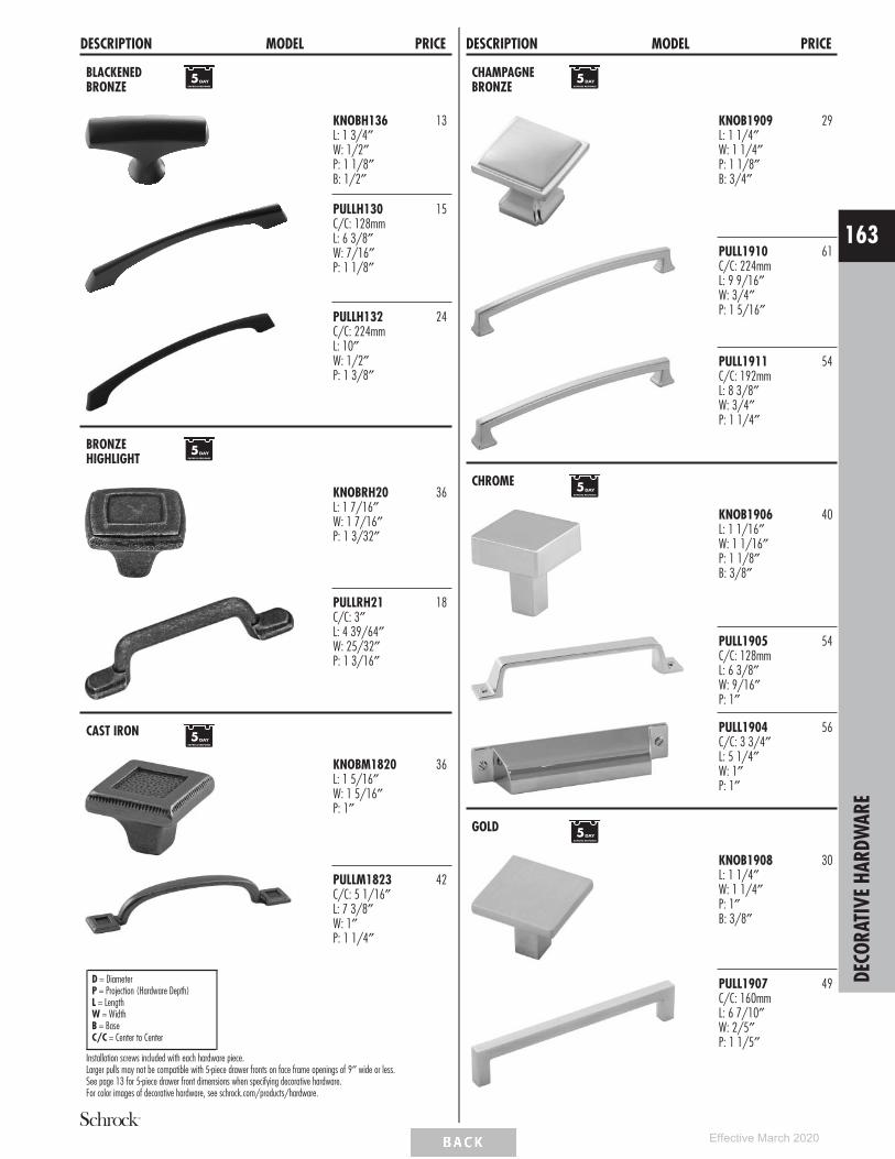
DESCRIPTION MODEL PRICE
BLACKENEDBRONZE
KNOBH136L: 1 3/4″W: 1/2″P: 1 1/8″B: 1/2″
13
PULLH130C/C: 128mmL: 6 3/8″W: 7/16″P: 1 1/8″
15
PULLH132C/C: 224mmL: 10″W: 1/2″P: 1 3/8″
24
BRONZEHIGHLIGHT
KNOBRH20L: 1 7/16″W: 1 7/16″P: 1 3/32″
36
PULLRH21C/C: 3″L: 4 39/64″W: 25/32″P: 1 3/16″
18
CAST IRON
KNOBM1820L: 1 5/16″W: 1 5/16″P: 1″
36
PULLM1823C/C: 5 1/16″L: 7 3/8″W: 1″P: 1 1/4″
42
D = DiameterP = Projection (Hardware Depth)L = LengthW = WidthB = BaseC/C = Center to Center
Installation screws included with each hardware piece.Larger pulls may not be compatible with 5-piece drawer fronts on face frame openings of 9″ wide or less.See page 13 for 5-piece drawer front dimensions when specifying decorative hardware.For color images of decorative hardware, see schrock.com/products/hardware.
DESCRIPTION MODEL PRICE
CHAMPAGNEBRONZE
KNOB1909L: 1 1/4″W: 1 1/4″P: 1 1/8″B: 3/4″
29
PULL1910C/C: 224mmL: 9 9/16″W: 3/4″P: 1 5/16″
61
PULL1911C/C: 192mmL: 8 3/8″W: 3/4″P: 1 1/4″
54
CHROME
KNOB1906L: 1 1/16″W: 1 1/16″P: 1 1/8″B: 3/8″
40
PULL1905C/C: 128mmL: 6 3/8″W: 9/16″P: 1″
54
PULL1904C/C: 3 3/4″L: 5 1/4″W: 1″P: 1″
56
GOLD
KNOB1908L: 1 1/4″W: 1 1/4″P: 1″B: 3/8″
30
PULL1907C/C: 160mmL: 6 7/10″W: 2/5″P: 1 1/5″
49 DECO
RATI
VEHA
RDW
ARE
163
Effective March 2020

DESCRIPTION MODEL PRICE
HAMMEREDBRONZE
KNOBH913L: 1 3/8″W: 1 3/8″
35
PULLH911C/C: 3″L: 5 5/8″W: 1″P: 1 1/4″
37
ICE TEA
KNOBH108L: 1 7/16″W: 11/16″P: 1″B: 1/2″
10
PULLH144C/C: 160mmL: 6 5/16″W: 9/16″P: 1 1/16″
21
RUST
KNOBM207D: 1 1/4″P: 1 1/16″
17
PULLM476C/C: 3 3/4″L: 5″W: 9/16″P: 1″
36
D = DiameterP = Projection (Hardware Depth)L = LengthW = WidthB = BaseC/C = Center to Center
Installation screws included with each hardware piece.Larger pulls may not be compatible with 5-piece drawer fronts on face frame openings of 9″ wide or less.See page 13 for 5-piece drawer front dimensions when specifying decorative hardware.For color images of decorative hardware, see schrock.com/products/hardware.
DESCRIPTION MODEL PRICE
SATIN NICKEL
KNOBT002C/C: 1 1/4″L: 2″W: 3/8″P: 1 1/2″Pairs best with PULLT001
39
PULLT001C/C: 7″L: 8″W: 3/8″P: 1 1/2″Pairs best with KNOBT002
27
PULLH120C/C: 160mmL: 7 1/8″W: 3/4″P: 1″Pairs best with PULLH122
25
PULLH122C/C: 12″L: 12 3/4″W: 7/8″P: 1 3/16″Pairs best with PULLH120
47
PULLH105C/C: 1″L: 1 3/4″W: 1″P: 1 3/4″Pairs best with PULLH106 orPULLH107
31
PULLH106C/C: 160mmL: 7″W: 1″P: 1 3/4″Pairs best with PULLH105 orPULLH107
44
PULLH107C/C: 12″L: 13″W: 1″P: 1 13/16″Pairs best with PULLH105 orPULLH106
70
DECO
RATI
VEHA
RDW
ARE
164
Effective March 2020

DESCRIPTION MODEL PRICE
SATIN NICKEL(cont’d)
KNOB1420D: 1 1/4″P: 1 1/8″
17
KNOBH100D: 1 3/8″P: 1 3/8″B: 3/4″
17
KNOBH118L: 1 5/16″W: 1 5/16″P: 1 3/16″B: 7/8″
15
KNOBM549D: 7/8″P: 1″
16
PULLH50C/C: 5″L: 5″W: 5/16″P: 1 1/4″
44
PULLH63C/C: 96mmL: 4 1/8″W: 1/2″P: 1 1/16″
35
PULLH957C/C: 3″L: 4 1/4″W: 1 1/2″P: 11/16″
26
D = DiameterP = Projection (Hardware Depth)L = LengthW = WidthB = BaseC/C = Center to Center
Installation screws included with each hardware piece.Larger pulls may not be compatible with 5-piece drawer fronts on face frame openings of 9″ wide or less.See page 13 for 5-piece drawer front dimensions when specifying decorative hardware.For color images of decorative hardware, see schrock.com/products/hardware.
DESCRIPTION MODEL PRICE
SATIN NICKEL(cont’d)
PULLM381C/C: 5 1/16″L: 6″W: 1/2″P: 1 1/16″
21
PULLM430C/C: 5 1/16″L: 7″W: 15/32″P: 1 7/16″
25
PULLM570C/C: 5 1/16″L: 5 7/8″W: 1/2″P: 1 3/16″
20
SILVER STONE
KNOBH127D: 1 1/2″P: 1″B: 7/8″
17
PULLH128C/C: 160mmL: 7 1/2″W: 3/4″P: 1 1/16″
27
DECO
RATI
VEHA
RDW
ARE
165
Effective March 2020

DESCRIPTION MODEL PRICE
STAINLESS STEEL
KNOBH135L: 1 3/4″W: 1/2″P: 1 1/8″B: 1/2″Pairs best with PULLH129 orPULLH131
13
PULLH129C/C: 128mmL: 6 3/8″W: 7/16″P: 1 1/8″Pairs best with KNOBH135 orPULLH131
15
PULLH131C/C: 224mmL: 10″W: 1/2″P: 1 3/8″Pairs best with KNOBH135 orPULLH129
23
PULLH141C/C: 128mmL: 7 3/8″W: 1/2″P: 1 1/4″Pairs best with PULLH142 orPULLH143
14
PULLH142C/C: 192mmL: 9 15/16″W: 1/2″P: 1 1/4″Pairs best with PULLH141 orPULLH143
16
PULLH143C/C: 384mmL: 17 1/2″W: 1/2″P: 1 1/4″Pairs best with PULLH141 orPULLH142
24
D = DiameterP = Projection (Hardware Depth)L = LengthW = WidthB = BaseC/C = Center to Center
Installation screws included with each hardware piece.Larger pulls may not be compatible with 5-piece drawer fronts on face frame openings of 9″ wide or less.See page 13 for 5-piece drawer front dimensions when specifying decorative hardware.For color images of decorative hardware, see schrock.com/products/hardware.
DESCRIPTION MODEL PRICE
TUSCAN BRONZE
KNOBH117L: 1 5/16″W: 1 5/16″P: 1 3/16″B: 7/8″Pairs best with PULLH119
15
PULLH119C/C: 160mmL: 7 1/8″W: 3/4″P: 1″Pairs best with KNOBH117
37
KNOBT013D: 1 1/4″P: 1 1/16″
31
PULLM1674C/C: 3″L: 4 5/8″W: 1 7/16″P: 15/16″
43
PULLT1018C/C: 5 1/16″L: 6″W: 1/2″P: 1 1/16″
29
DECO
RATI
VEHA
RDW
ARE
166
Effective March 2020

DESCRIPTION MODEL PRICEACCESSORIES
CABMAT™
281/4”, 311/4”, or 341/4”221/4”
CABMAT30 275
CABMAT33 285
CABMAT36 296
• Designed to capture spills and is removable for cleaning.• See CabMat™ modification for easy size selection by
cabinet model.• Not trimmable. Can also be used in wider cabinets but will
create a small void of unprotected area along the endpanels.
Liquid Capacity Cabinet SizeModel Gallons Liters Width DepthCABMAT30 2.0 7.6 30″ 24″CABMAT33 2.4 9.0 33″ 24″CABMAT36 2.7 10.2 36″ 24″
CABMAT™ VANITY
221/4”, 281/4”, or 341/4”199/16”
CABMATV24 265
CABMATV30 275
CABMATV36 296
• Designed to capture spills and is removable for cleaning.• See CabMat™ modification for easy size selection by
cabinet model.• Not trimmable. Can also be used in wider cabinets but will
create a small void of unprotected area along the endpanels.
Liquid Capacity Cabinet Size
Model Quarts LitersFace Frame
Opening DepthCABMATV24 2.5 2.4 21″-24″ 21″CABMATV30 3.3 3.1 27″-30″ 21″CABMATV36 3.9 3.7 33″ 21″
DESCRIPTION MODEL PRICE
COOKING UTENSILDIVIDER
25/8”
191/2”191/4”
25/8”
191/2”251/4”
25/8”
191/2” 311/4”
CUDD24 258
CUDD30 287
CUDD36 316
• Pre-assembled natural wood drawer insert (does not fitroll trays).
CUTLERY INSERT WOODORGANIZER
25/8”
191/2”101/4”
25/8”
191/2”131/4”
25/8”
191/2” 161/4”
25/8”
191/2” 191/4”
CIW15 177
CIW18 188
CIW21 245
CIW24 263
Model ApplicationCIW15 15″ Base
CIW18 18″ Base
CIW21 21″ Base
CIW24 24″ Base
• Pre-assembled natural wood drawer insert.• Place a cabinet with a CIW next to the dishwasher for
convenience.
ACCE
SSOR
IES
167
Effective March 2020

DESCRIPTION MODEL PRICE
WOOD TIERED CUTLERYDIVIDER DRAWER,15″, 18″, 21″, and 24″
33/4”
117/16”
21”
201/4”
911/16”
bottom top
33/4”
147/16”
21”
201/4”1211/16”
bottom top
33/4”
177/16”
21”
201/4”1511/16”
bottom top
33/4”
207/16”21”
201/4”1811/16”
bottom top
WTCD15 474
WTCD18 490
WTCD21 510
WTCD24 527
Model ApplicationWTCD15 15″ Base
WTCD18 18″ Base
WTCD21 21″ Base
WTCD24 24″ Base
• Replaces standard drawer. Uses existing cabinet memberdrawer hardware.
• Requires field installation of drawer front.• For use with 24″ deep cabinets only.• Exterior WTCD drawer box height is 3 3/4″, interior
height of top tier is 1 5/8″, and interior height of bottomtier is 1 3/8″.
• Top divider slides front-to-back.
DESCRIPTION MODEL PRICE
ANGLED HEAT SHIELDS
30”
7/8”
3/8” Radius5/8”
7/8
5/8
ANGLHEATSHIELD 141
ANGLHSHIELDSS 161
• ANGLHEATSHIELD is a pair of 1/16″ thick, white powdercoated metal shields.
• ANGLHSHIELDSS is a pair of 1/16″ thick, stainless steelmetal shields.
• Heat Shield is used to deflect heat from self-cleaningovens away from cabinet doors and drawer fronts.
• For use when additional 1/8″ cannot be added to theoven manufacturer’s recommended space requirement.
• Cabinet door cannot be hinged on the same side as theangled heat shield, not compatible with double doorcabinets. Installs on the front of the face frame of eachcabinet adjacent to the oven.
STRAIGHT HEAT SHIELDS
30”
121/32”3/8” Radius
STRTHEATSHIELD 106
STRTHSHIELDSS 126
• STRTHEATSHIELD is a pair of 1/16″ thick, white powdercoated metal shields.
• STRTHSHIELDSS is a pair of 1/16″ thick, stainless steelmetal shields.
• Heat Shield is used to deflect heat from self-cleaningovens away from cabinet doors and drawer fronts.
• For use when additional 1/8″ can be added to the ovenmanufacturer’s recommended space requirement.
• Installs on the side of the face frame of each cabinetadjacent to the oven.
OVEN INSTALLATION KIT
4”
3”
239/16”
OCINSTALLKIT 59
• Recommended for supporting built-in appliances such asovens, microwaves, and warming drawers. Refer toappliance manufacturer specifications for installationrequirements.
• Weight limit is 400 lbs. per pair.
PEGGED DISH ORGANIZER PDO (8 Posts & Board) 364
PDOPOSTS (4 Posts) 93
• For use in 36″ wide drawer base cabinets in 6 3/8″ or10″ deep drawers, trimmable for cabinets less than 36″wide. Not recommended for use in roll trays.
• Pegged Board is 19/32″ thick.• 29 15/16″ x 19 1/2″.• Posts are 6″ high.
ACCE
SSOR
IES
168
Effective March 2020

DESCRIPTION MODEL PRICE
SPICE RACK PULL-DOWN SPD18 217
• Spice Rack Pull-down dimensions: 8 15/16″ high x14 13/16″ wide x 10 5/16″ deep.
• Spice Rack Pull-down requires 3 3/4″ below the bottomedge of the cabinet and 9 1/4″ in front of the cabinet tobe fully extended.
• Maximum Weight Capacity: 15 lbs.• Must be installed on the floor of the cabinet. Cannot be
installed on an adjustable shelf.
TABLET HOLDER
111/4”
81/2”
133/8” 103/8”
TABLETHLDR 242
• Mounts under 15″ wide cabinet or wider.• Designed for cabinets 12″ deep or deeper.• Features an acrylic mounting base and pull-down tablet
holder tray.• Tray is movable forward and backward with a slight side
to side rotation, and can be utilized at any position.• Tray has side cut-outs for a charging cord and can be used
to store most tablets when closed, depending on overallthickness, width, and height of the tablet.
• Maximum dimensions for tablet: 11 1/4″ x 8 1/2″ x1 1/8″ thick.
• Tablet Holder has an overall height of 1 17/32″ wheninstalled and in closed position (measured from thebottom panel of the cabinet), 0.78″ visible from front ofcabinet when closed.
• Installation instructions included.
TILT-OUT TRAYS, PLASTIC
33/4”
11” or 141/4”
2”
TOT15 96
TOT18 101
• Kit includes two white plastic trays and one pair of tilt-outhinges that attaches to the inside of the false panel.
• One tilt-out tray per false panel on cabinets less than 30″wide and greater than 36″ wide, two tilt-out traysattached to one false panel on 30″-36″ wide cabinets.
• Clean using a mild soap and water. Avoid scalding water.
Model Size ApplicationTOT15 11″w x 2″d x 3 3/4″h SB30, SB33
TOT18 14 1/4″w x 2″d x 3 3/4″h SB36, SB39,SB42, SB24,SB27
TRAY DIVIDER KIT
121/4”
193/4”
CTDK 56
• CTDK: Includes 1 divider, 3 clips, and 3 screws.• Tray divider is chrome wire.
DESCRIPTION MODEL PRICE
TRAY DIVIDERROLL-OUT KIT
23/32”Opening Width
21”
10”
79/16”
21/2”
TDRO12
25/16”Opening Width
21”
10”
109/16”
21/2”
TDRO15
TDRO12 306
TDRO15 343
• TDRO12: 2 removable dividers (3 compartments).• TDRO15: 3 removable dividers (4 compartments).• Utilizes Smart Stop undermount guides and bumpers for
door protection.• Installation hardware included.
WINE GLASS HOLDERS
1011/16”281/4”
1011/16” 341/4”
WGH30 (7 slots) 260
WGH36 (8 slots) 317
• Maximum wine glass base is 3″ diameter.• May be trimmed to fit smaller cabinets.• Designed for installation under a wall cabinet (between
end panels and behind face frame).
Species AvailabilityPainted
HardwoodStained
Hardwood• •
ACCE
SSOR
IES
169
Effective March 2020

DESCRIPTION MODEL PRICEROLL TRAY KITS
ROLL TRAY KIT
31/2”
Standard
33/8”
SC
RT12 174
RT15 174
RT18 176
RT21 181
RT24 183
RT27 184
RT30 185
RT33 187
RT36 191
RT12SC 206
RT15SC 206
RT18SC 208
RT21SC 213
RT24SC 215
RT27SC 216
RT30SC 217
RT33SC 219
RT36SC 223
Width Application12″ B12, U12
15″ B15, U15
18″ B18, U18
21″ B21, B42
24″ B24, U24
27″ B27
30″ B30, B30RT, U30
33″ B33, B33RT
36″ B36, B36RT, U36
• RT and RT_ _SC include roll tray, roll tray brackets,hardware, screws, and installation instructions.
• Exterior dimensions of roll tray are 21″ deep x 3 3/8″tall (fits standard 24″ deep cabinet).
• Reduced Depth upcharge is applied if roll tray is orderedfor a reduced depth cabinet (minimum depth 18″).
• RD only available on SC models.Custom Modifications
ID RD•
DESCRIPTION MODEL PRICEGUIDE KITS AND PARTS
DRAWER GUIDE KITS21” or 24”
DGK_ _DDFX
DGK21DDFX 272
DGK24DDFX 272
• Side-mount progressive full extension guide utilized on alldrawers of DDFD____ cabinets.
• 125 lb. weight capacity per pair.• Kit includes guide hardware for one drawer box (cabinets,
drawer members wood vertical mounting rails andscrews).
• Dimension refers to cabinet depth.
18”, 21”, or 24”
DGKIT_ _SC
DGKIT18SC 238
DGKIT21SC 238
DGKIT24SC 238
• Undermount full extension Smart Stop Premium Guide.• 75 lb. weight capacity per pair.• Kit includes guide hardware for one drawer box (cabinets
and drawer members, sockets and screws).• Dimension refers to cabinet depth.
15”, 18”, 21”, or 24”
DGK_ _SM
DGK18SM 36
DGK21SM 36
DGK24SM 36
• SM−Furniture board drawer side-mount guide used ondrawers with NSCFB mod.
• 75 lb. weight capacity per pair.• Kit includes guide hardware for one drawer box (cabinets
and drawer members, sockets and screws)• Dimension refers to cabinet depth.
15”, 18”, 21”, or 24”
DGK_ _RT
DGK18RT 36
DGK21RT 36
DGK24RT 36
• Side-mount guide used on roll trays with NSCFB mod.• 3/4 extension.• 75 lb. weight capacity per pair.• Kit includes guide hardware for one drawer box (cabinets
and drawer members, sockets and screws).• Dimension refers to cabinet depth.
18”, 21”, or 24”
DGKIT_ _RTSC
DGKIT18RTSC 238
DGKIT21RTSC 238
DGKIT24RTSC 238
• Undermount full extension Smart Stop Premium Guide.• 75 lb. weight capacity per pair.• Kit includes guide hardware for one drawer box (cabinets
and drawer members, sockets and screws).• Dimension refers to cabinet depth.
DRAWER GUIDEBACK SOCKETS
BKSOCKET-SC 45
BKSOCKET-RTSC 45
DGK-BKSCKT-RDSM 45
DGK-BKSCKT-24SM 45
• BKSOCKET-SC used with Smart Stop drawer guides(12″-24″ deep).
• BKSOCKET-RTSC used with Smart Stop roll tray guides.• DGK-BKSCKT-RDSM used with side-mount drawer guides
(15″, 18″, 21″ deep) (NSCFB mod).• DGK-BKSCKT-24SM used with side-mount drawer guides
(24″ deep) (NSCFB mod).• Sold in pairs.RO
LLTR
AYKI
TS/
GUID
EKI
TSAN
DPA
RTS
170
Effective March 2020

DESCRIPTION MODEL PRICE
FALSE PANEL CLIP FALSEPNLCLIP5O 8 /pair
PFALSEPNLCLIP5O 8 /pair
• Clips come in pairs of two.• Use to secure false front on sink base.
ROLL TRAYPLUG IN BRACKET
RTBK
RTBKSXSP
RTBK 46
RTBKSXSP 46
• For use with roll tray hardware to prevent interferencewith door hinges. Also included in roll tray hardware kit.
• RTBK for use with roll trays with NSCFB mod.• RTBKSXSP for use with standard roll trays.• Includes four end panel brackets, two vertical stile
brackets, and screws.
STAIN, PAINT, & TOUCH-UP TOOLS
STAIN & PAINT QUARTCOLOR 170
SSC 60
SSCCLEAR 60
• Wiping stains can be sprayed at low pressure.• Specify finish name and wood type when ordering stain.• QUARTCOLOR sold in quarts. Not available in Ashen Strata
and Kona. Available for their selected box color.• SSC are 384 mL aerosol cans available in Paint colors and
clear.
TOUCH-UP TOOLS
TUK
MTUK
TUK 84
MTUK 42
• Touch-up Kit includes a full size touch-up marker and an8 cm fill stick.
• Mini Touch-up Kit includes a small touch-up marker and a4 cm small fill stick.
PURE&SIMPLE™
CABINET CARE KITCABCLEANKIT 50
• PURE&SIMPLE™ Cabinet Care Kit includes one 16 ouncespray bottle of cleaning solution and a small microfibercloth.
• Safe for use on wood and laminate cabinet surfaces.
DESCRIPTION MODEL PRICEHINGES
HINGES 38NPOHINGE Partial Overlay Hinge, 6-wayAdjustable with integrated Smart Stop• Sold in pairs.• 1/2″ partial overlay 107° hinge.• For use on full overlay styles: Wall and Base Transition
Cabinets, Diagonal Wall and Base Cabinets, and AngledCorner Sink Bases and Fronts.
29
38CFOHINGE Full Overlay Hinge, 6-way Adjustablewith integrated Smart Stop• Sold in pairs.• 107° full overlay hinge.• For use on all cabinets not specified by other hinges.
29
38BFOVHINGE Full Overlay Hinge, 6-way Adjustablewith integrated Smart Stop• Sold in pairs.• Full overlay, face mount 107° hinge.• For use on OCD, OCS, OMC, and 30″-42″ high WBMW
cabinets.
29
2925HINGE - 6-way Adjustable, 1/2″ PartialOverlay, 107° Hinge• Sold in pairs.• All cabinets not specified by other hinges.
23
2933HINGE - 6-way Adjustable, 1 1/4″ FullOverlay, 107° Hinge• Sold in pairs.• All cabinets not specified by other hinges.
23
1351HINGE - 4-way Adjustable, Full Overlay,Face-mount 107° Hinge• Sold in pairs.• For use on OCD, OCS, OMC, and 30″-42″ high WBMW
cabinets.
10
32049HINGE - 90° Corner Self-closing Center Hinge• Sold in pairs.• Center Hinge for ER, BLS, SLS, and BER
76
942HINGE - 170° Hinge 3/4″ Overlay and 90°Corner Full/Partial Overlay Door toFrame• Sold in pairs.• BSC, BLS, SLS, ER, and BER
64
7299HINGE - Mirror Hinge• Sold in pairs.• TV and MC cabinets
11
HINGE ANGLERESTRICTION CLIP
HINGERESCLIP 11
• For use in applications with cabinets installed at varyingdepths to prevent the door damage caused by openinginto an adjacent cabinet.
• Restricts hinges to 86° opening capability.• Works only with the 38NPOHINGE and 38CFOHINGE.• Not recommended for cabinets with roll trays specified in
partial overlay styles.• Sold in pairs.
HINGE SHIM HINGESHIM5 16
• Install between the face frame and hinge to allowadditional adjustment of doors. Can be used to reduce gapbetween butt doors.
• Pack of 5 metal shims.• Compatible with all hinges except face-mount.
STAI
N,PA
INT,
&TO
UCH-
UPTO
OLS
/HI
NGES
171
Effective March 2020

DESCRIPTION MODEL PRICE
TOUCH LATCH TOUCHLATCH 33
• Nylon gray mechanism with bumper tip.• Face frame will need to be field drilled for insertion of the
TOUCHLATCH, requires 25/64″ (10mm) drill bit.• Can be field adjusted for door gap depth, no tools
required.• For use on full overlay door styles only.• Requires a soft touch to open the door, and door must be
pushed closed to reset the TOUCHLATCH mechanism.• Only for use on hinged doors, and can be used without
decorative hardware. Not compatible with non-hingeddoors. For drawers, pull-outs, and other non-compatiblecabinets, PULLH105, PULLH106, and PULLH107 arerecommended (see page 164).
DESCRIPTION MODEL PRICEDOORS, DRAWER FRONTS, AND DRAWERS
DOORS & DRAWERFRONTS
Standard Door Size, 18″ High or Less 268
Standard Door Size, 21″ to 30″ High 336
Standard Door Size, 33″ or Higher 473
Standard Door Size, No Hinge Route,18″ High or Less
268
Standard Door Size, No Hinge Route,21″ to 30″ High
336
Standard Door Size, No Hinge Route,33″ or Higher
473
Any Drawer Front Only 124
• All applicable modification and premium finish upcharges will apply.• Door heights are based on full overlay for equivalent applications.• Backs of ‘‘NO HINGE ROUTE’’ doors may have identification marks, be
unfinished, and have 3/16" diameter holes used during finishprocessing. For these reasons, these doors are not suitable for use ascabinet doors.
DRAWERS Complete Drawer 198
Drawer Box Only 176
• All applicable modification and premium finish upcharges will apply.• Complete Drawer and Drawer Box Only do not include drawer guides.
They must be ordered separately.
PARTS
MISCELLANEOUS PARTS
PDM
SHELFPEGS
1.405”
.960”
.25”
.05”
.395”
SHELFPEGSCTR
BRKOFFSCREW (pkg. 25) 5
INSTALLSCR24 (pkg. 24) 12
INSTALLSCREWS (pkg. 100) 41
TVHDW/WCATCH 123
MC16HDW/WCATCH 64
RETCLIP250BAG 20
BUMPERPADS (pkg. 25) 7
PDM 24
SHELFPEGS (pkg. 24) 10
SHELFPEGSCTR (pkg. 6) 5
• BRKOFFSCREW is a pack of 25 breakaway screws for usewith decorative hardware pulls and knobs.
• INSTALLSCR24 and INSTALLSCREWS are screws forcabinet installation through the cabinet back to the wallstuds (includes a pack of 24 or 100).
• TVHDW/WCATCH is one set of the magnetic catchhardware and handle used on mirrors on Tri-View Mirrors(TV..).
• MC16HDW/WCATCH is one set of the magnetic catchhardware, handle, and one pair of hinges used on SingleDoor Medicine Cabinets (MC16).
• RETCLIP250BAG: 6 retainer clips for use with glass insertsin mullion and cut-for-glass doors.
• PDM creates a smooth and silent self-closing motion andincludes all installation hardware.
• SHELFPEGS are 3mm steel pins with clear plasticshoulders.
• SHELFPEGSCTR is a package of 6 clear plastic shelf clipswith 0.96" usable depth with 1/4" diameter pegs. Foruse on center mullions of full depth shelves.
PART
S
172
Effective March 2020

DESCRIPTION MODEL PRICESTACK MOULDING KITS
• Moulding stacks do not ship assembled; field assembly is required. Assemblyinstructions can be viewed in 20/20 spec pages and will also ship with mouldingkits.
• When ordered as a kit, only one finish can be specified. To order with more thanone finish, moulding pieces must be ordered separately.
• Moulding stacks include Assembly Instructions. Cleats and finish nails not included.• How to place a stack moulding in 20/20:
→ Moulding→ Top Mouldings or Bottom Mouldings→ Stacked Mouldings→ Drag and drop desired moulding stack onto wall cabinets
• Mouldings specified as 8′ nominal length have a usable length range of 93″ up to99″. Be sure to order the correct amount of moulding length to work aroundrequired cuts with minimal butt joints.
MOULDING STACK 1
TBP8
Finish Nails*
Finish Nails*
Finish Nails*
Finish Nails*
Finish Nails*
Finish Nails*
Cleat*
Cleat*
Cleat*1
2
3
SWCRM8
ICM8
TF396FH
TBP8
Top of Cabinet
Face Frame
Door1"
61/8"
STKMLD1C 1044
Species AvailabilityPainted
HardwoodStained
HardwoodTBP8 • •SWCRM8 • •ICM8 • •TF396FH • •
*Cleats and finish nails not included.
MOULDING STACK 2
3/4"1/2"
1/16" Space
SWVCRM8
Finish Nails*
Finish Nails*
Cleat*
Cleat*
2
3
VFR8
TF396FH
Top of Cabinet
Face Frame(3/4" Thick)
77/16"
VFR8
Cleat*
1
Door
STKMLD2C 705
Species AvailabilityPainted
HardwoodStained
HardwoodSWVCRM8 • •VFR8 • •TF396FH • •
*Cleats and finish nails not included.
MOULDING STACK 3
1/16" Space
SWVCRM8
Finish Nails*
Finish Nails*
Cleat*
Cleat*1
2
3
LB2
Top of Cabinet
Face Frame
63/16"
TBP8
Door
Finish Nails*
1"
Cleat*
VFR8
STKMLD3C 796
Species AvailabilityPainted
HardwoodStained
HardwoodSWVCRM8 • •LB2 • •VFR8 • •TBP8 • •
*Cleats and finish nails not included.
STAC
KM
OULD
ING
KITS
173
Effective March 2020

DESCRIPTION MODEL PRICE
MOULDING STACK 6SHKRCRM8Finish Nails*
Finish Nails*
Cleat*
SM8
Top of Cabinet
Face Frame
5"
SM8
3/4"
Finish Nails*
TF396FHFinish Nails*
Door
STKMLD6C 518
Species AvailabilityPainted
HardwoodStained
HardwoodSHKRCRM8 • •SM8 • •TF396FH • •
*Cleats and finish nails not included.
MOULDING STACK 11
SWVCRM8
Finish Nails*
Finish Nails*
Cleat*
Cleat* 1
2
TF696FH
Top of Cabinet
Face Frame
91/16"
TCM8
Door
Finish Nails*
11/16"
STKMLD11C 735
Species AvailabilityPainted
HardwoodStained
HardwoodSWVCRM8 • •TF696FH • •TCM8 • •
*Cleats and finish nails not included.
MOULDING STACK 13
Cleat*LB2
Top of Cabinet
Face Frame
25/16"
Door
Finish Nails*
Finish Nails*
Finish Nails*LB2LB2
17/16"
STKMLD13C 342
Species AvailabilityPainted
HardwoodStained
HardwoodLB2 • •
*Cleats and finish nails not included.
MOULDING STACK 14
Cleat*
LB2
Top of Cabinet
Face Frame
33/32"
Door
Finish Nails*
Finish Nails*
Finish Nails*
TF396FH
LB2
11/4"
STKMLD14C 445
Species AvailabilityPainted
HardwoodStained
HardwoodLB2 • •TF396FH • •
*Cleats and finish nails not included.
STAC
KM
OULD
ING
KITS
174
Effective March 2020

DESCRIPTION MODEL PRICE
MOULDING STACK 20
SWCRM8
Top of Cabinet
Face Frame
Door
Finish Nails*
Finish Nails*Cleat*
VV96
Ceiling
41/2"
Finish Nails*
STKMLD20C 376
Species AvailabilityPainted
HardwoodStained
HardwoodSWCRM8 • •VV96 • •
*Cleats and finish nails not included.
MOULDING STACK 21
TF396FH
SWLCRM8
2
1
Cleat*
Top of Cabinet
Face Frame
Door
VFR8
Finish Nails*
Finish Nails*
Cleat*Finish Nails*
47/16"
11/4"Finish Nails*
STKMLD21C 568
Species AvailabilityPainted
HardwoodStained
HardwoodSWLCRM8 • •TF396FH • •VFR8 • •
*Cleats and finish nails not included.
MOULDING STACK 22
SWVCRM8
SBE8
Top of Cabinet
Face Frame
Door
Finish Nails*
Finish Nails*
SFM8
SFM8 CLEAT
711/16"
Finish Nails*
Finish Nails*
11/4"
STKMLD22C 807
Species AvailabilityPainted
HardwoodStained
HardwoodSWVCRM8 • •SBE8 • •SFM8 • •
*Cleats and finish nails not included.
STAC
KM
OULD
ING
KITS
175
Effective March 2020

PAINTED HARDWOOD FINISH AGREEMENT
Dear Schrock Customer,
Congratulations on your selection of Schrock cabinetry in a Painted Hardwood finish. Because of its unique characteristics, thisfinish is quite different from other cabinetry finishes you may be familiar with. Your satisfaction is important to Schrock, and wewant you to fully understand the characteristics that make painted finishes so distinctive.
It is important to realize that the beauty of wood cabinetry comes from the natural qualities of wood itself. Schrock utilizes onlyselect solid hardwoods and veneers. The beauty of these genuine woods lies in the variation of the grain. The textures of thosenatural grain patterns often remain visible with Painted Hardwood finishes and should be accepted as inherent characteristics whenselecting painted cabinetry.
Seam lines and hairline cracking at stile, rail and panel joints are a normal characteristic of painted finishes and should not beconsidered a reason for product replacement. When ordering Painted Hardwood 5-piece styles, the door’s center panel will beconstructed of MDF material. Over time, there may be a slight color shift in the Painted Hardwood finish due to the continuedexposure to natural and artificial light sources. We mention these characteristics because neither Schrock nor your Schrock dealercan be responsible for these conditions and variations.
Example of front joint separation Example of front joint separation Example of end joint separation
Accordingly, we ask that the following agreement be signed for Painted Hardwood Finish orders.
I have read the foregoing and find the characteristic variations of Painted Hardwood finish to be desirable.As such, I agree not to hold Schrock and/or the Schrock dealer listed below responsible in the event that these characteristics arelater found by me to be less desirable than I had expected.
Customer Signature Dealer Signature
Customer Name (please print) Dealer Name (please print)
Dealer Purchase Order Number
PAIN
TED
HARD
WOO
DFI
NISH
AGRE
EMEN
T
176
Effective March 2020

CodePageNumber
2DB . . . . . . . . . . . . . . . . . 952DB..DR . . . . . . . . . . . . . . 952DB..RT . . . . . . . . . . . . . . . 952VSD . . . . . . . . . . . . . . . . 1363DB . . . . . . . . . . . . . . . . . 96, 104,
1293DB..WTCD . . . . . . . . . . . . 963DBDD . . . . . . . . . . . . . . . 964DB . . . . . . . . . . . . . . . . . 974DB..WTCD . . . . . . . . . . . . 974VDB . . . . . . . . . . . . . . . . 134ACS . . . . . . . . . . . . . . . . . 88ANGLHEATSHIELD . . . . . . . . . 168ANGLHSHIELDSS . . . . . . . . . .168APW . . . . . . . . . . . . . . . . . 12AUTHL, AUTHR . . . . . . . . . . . 15AV . . . . . . . . . . . . . . . . . . 156B . . . . . . . . . . . . . . . . . . . 80, 103B..DR . . . . . . . . . . . . . . . . 100B..FH . . . . . . . . . . . . . . . . 81B..RT . . . . . . . . . . . . . . . . 83B..RTWTCD . . . . . . . . . . . . . 83B..TDRO . . . . . . . . . . . . . . 84B..WTCD . . . . . . . . . . . . . . 81BATTLTI . . . . . . . . . . . . . . . 159BBCPO . . . . . . . . . . . . . . . 99BBM . . . . . . . . . . . . . . . . . 154BBMSH . . . . . . . . . . . . . . . 154BBMWD . . . . . . . . . . . . . . 100BC . . . . . . . . . . . . . . . . . . 91BCF . . . . . . . . . . . . . . . . . 146BCP . . . . . . . . . . . . . . . . . 101BCP..FH . . . . . . . . . . . . . . . 102BEC . . . . . . . . . . . . . . . . . 94BEDSD . . . . . . . . . . . . . . . 151BEP . . . . . . . . . . . . . . . . . 149BEPF . . . . . . . . . . . . . . . . 150BEPS . . . . . . . . . . . . . . . . 147BER . . . . . . . . . . . . . . . . . 92BKSOCKET . . . . . . . . . . . . . 170BLOWER . . . . . . . . . . . . . . 79BLS . . . . . . . . . . . . . . . . . 91BLSBEP . . . . . . . . . . . . . . . 149BLVDFF . . . . . . . . . . . . . . . 146BMWD . . . . . . . . . . . . . . . 101BMWD..DD . . . . . . . . . . . . . 101BO . . . . . . . . . . . . . . . . . . 100BP . . . . . . . . . . . . . . . . . . 148BP..CRSGR . . . . . . . . . . . . . 148BP..VG . . . . . . . . . . . . . . . . 148BP4896LAM . . . . . . . . . . . . 148BPP . . . . . . . . . . . . . . . . . 98BPPP . . . . . . . . . . . . . . . . 84BRKOFFSCREW . . . . . . . . . . 172BSC30PR . . . . . . . . . . . . . . 82BSC30RP . . . . . . . . . . . . . . 82BSC36PRP . . . . . . . . . . . . . 82BTC . . . . . . . . . . . . . . . . . 94BUMPERPADS . . . . . . . . . . . 172BUPP . . . . . . . . . . . . . . . . 99BUPPKB . . . . . . . . . . . . . . . 99BWB . . . . . . . . . . . . . . . . 97BWB..FH . . . . . . . . . . . . . . 98BWC . . . . . . . . . . . . . . . . . 98CABCLEANKIT . . . . . . . . . . . 171CABMAT . . . . . . . . . . . . . . . 167CABMATV . . . . . . . . . . . . . . 167CAPM . . . . . . . . . . . . . . . . 155CBO . . . . . . . . . . . . . . . . . 17CCO . . . . . . . . . . . . . . . . . 17CD . . . . . . . . . . . . . . . . . . 71CFNTO . . . . . . . . . . . . . . . 23CFP . . . . . . . . . . . . . . . . . 17CG . . . . . . . . . . . . . . . . . . 24CIW . . . . . . . . . . . . . . . . . 167CLTCROWN . . . . . . . . . . . . . 152CMAT . . . . . . . . . . . . . . . . 19CND . . . . . . . . . . . . . . . . . 17
CodePageNumber
CNTYSB . . . . . . . . . . . . . . . 89CNTYSB..CM . . . . . . . . . . . . 89CONVERSION . . . . . . . . . . . 79CORBELART9 . . . . . . . . . . . . 159CORBELMIS6 . . . . . . . . . . . 159CORBELMIS9 . . . . . . . . . . . 159CORBELOWD5 . . . . . . . . . . . 159CORBELSCR9 . . . . . . . . . . . 159COVECROWN . . . . . . . . . . . 152CPE . . . . . . . . . . . . . . . . . 153CTDK . . . . . . . . . . . . . . . . 169CUDD . . . . . . . . . . . . . . . . 167DAB..FS . . . . . . . . . . . . . . . 92DAB..SLS . . . . . . . . . . . . . . 92DB . . . . . . . . . . . . . . . . . . 94-97DDFD . . . . . . . . . . . . . . . . 130DDO . . . . . . . . . . . . . . . . . 129DFD . . . . . . . . . . . . . . . . . 129DFF5PC . . . . . . . . . . . . . . . 13DFSLB . . . . . . . . . . . . . . . . 13DGK . . . . . . . . . . . . . . . . . 170DLEGMISSION . . . . . . . . . . . 157DW . . . . . . . . . . . . . . . . . 64DW..S . . . . . . . . . . . . . . . . 66ENGBARCOLUMN . . . . . . . . . 156ENGISLCOLUMN . . . . . . . . . . 156ER . . . . . . . . . . . . . . . . . . 67ES . . . . . . . . . . . . . . . . . . 160F . . . . . . . . . . . . . . . . . . . 145FALSEPNLCLIP5O. . . . . . . . . . .171FB . . . . . . . . . . . . . . . . . . 15FBF . . . . . . . . . . . . . . . . . 146FD . . . . . . . . . . . . . . . . . . 19, 130FDWB . . . . . . . . . . . . . . . . 131FPEB . . . . . . . . . . . . . . . . 15FS . . . . . . . . . . . . . . . . . . 160FTK . . . . . . . . . . . . . . . . . 20FV . . . . . . . . . . . . . . . . . . 156HINGE . . . . . . . . . . . . . . . . 171HNGRESCLIP . . . . . . . . . . . . 171HINGESHIM . . . . . . . . . . . . 171ICM . . . . . . . . . . . . . . . . . 155ID . . . . . . . . . . . . . . . . . . 18INSCROWN . . . . . . . . . . . . . 152INSTALLSCR, INSTALLSCREWS . . 172ISLEG . . . . . . . . . . . . . . . . 157ISLEGTPRD . . . . . . . . . . . . . 157JBRACKETART . . . . . . . . . . . 159JCRAFTFOOT . . . . . . . . . . . . 158JESTATELEGS . . . . . . . . . . . . 156JGSK . . . . . . . . . . . . . . . . 161JRPV . . . . . . . . . . . . . . . . 156JSQISLLEG . . . . . . . . . . . . . 157JWSHIPC . . . . . . . . . . . . . . 77JWSHIPT . . . . . . . . . . . . . . 77KNOB . . . . . . . . . . . . . . . . 162LB . . . . . . . . . . . . . . . . . . 155LBRM . . . . . . . . . . . . . . . . 154LC . . . . . . . . . . . . . . . . . . 142LCRH . . . . . . . . . . . . . . . . 142LGCORBEL . . . . . . . . . . . . . 159LGSQFOOT . . . . . . . . . . . . . 158LIFOOT . . . . . . . . . . . . . . . 158LRM . . . . . . . . . . . . . . . . . 155LSACROWN . . . . . . . . . . . . . 152LSHAKER . . . . . . . . . . . . . . 152MC . . . . . . . . . . . . . . . . . 143MC16HDW/WCATCH . . . . . . . 172MD . . . . . . . . . . . . . . . . . 25METBARCOLUMN . . . . . . . . . 157METISLCOLUMN . . . . . . . . . . 157MIP . . . . . . . . . . . . . . . . . 16MSACROWN . . . . . . . . . . . . 152MTCROWN . . . . . . . . . . . . . 152MTUK . . . . . . . . . . . . . . . . 171MW . . . . . . . . . . . . . . . . . 68NSCFB . . . . . . . . . . . . . . . 14NSCH . . . . . . . . . . . . . . . . 14
CodePageNumber
OC135 . . . . . . . . . . . . . . . 155OCD . . . . . . . . . . . . . . . . . 118OCD..DD . . . . . . . . . . . . . . 120OCINSTALLKIT . . . . . . . . . . . 168OCM . . . . . . . . . . . . . . . . 155OCS . . . . . . . . . . . . . . . . . 116OSB . . . . . . . . . . . . . . . . . 114OGEEM . . . . . . . . . . . . . . . 154OL . . . . . . . . . . . . . . . . . . 145OMC . . . . . . . . . . . . . . . . 122OMC..DD . . . . . . . . . . . . . . 125P . . . . . . . . . . . . . . . . . . . 23PDM . . . . . . . . . . . . . . . . . 172PDO, PDOPOSTS . . . . . . . . . 168PFALSEPNLCLIP5O . . . . . . . . . 171PLE . . . . . . . . . . . . . . . . . 12PULL . . . . . . . . . . . . . . . . 162QRM . . . . . . . . . . . . . . . . 155QUARTCOLOR . . . . . . . . . . . 171RD . . . . . . . . . . . . . . . . . . 18RECTKALL . . . . . . . . . . . . . . 22RECTKBK . . . . . . . . . . . . . . 22RECTKL, RECTKR . . . . . . . . . . 22RETCLIP..BAG . . . . . . . . . . . . 172ROSETTEMIS . . . . . . . . . . . . 156RT . . . . . . . . . . . . . . . . . . 19RT, RT..SC . . . . . . . . . . . . . 170RTBK, RTBKSXSC . . . . . . . . . 171RVWS . . . . . . . . . . . . . . . . 105SACROWN . . . . . . . . . . . . . 152SB . . . . . . . . . . . . . . . . . . 85-86,
103SB..CM . . . . . . . . . . . . . . . 86SB..ST . . . . . . . . . . . . . . . 86SB..STCM . . . . . . . . . . . . . 87SB..STS . . . . . . . . . . . . . . . 87SB..STSCM . . . . . . . . . . . . . 87SBC . . . . . . . . . . . . . . . . . 90SBE . . . . . . . . . . . . . . . . . 154SBS . . . . . . . . . . . . . . . . . 159SFM . . . . . . . . . . . . . . . . . 153SHELFPEGS, SHELFPEGSCTR . . . 172SHKRCRM . . . . . . . . . . . . . 152SHM . . . . . . . . . . . . . . . . 155SK . . . . . . . . . . . . . . . . . . 160SLS . . . . . . . . . . . . . . . . . 93, 104SLSW . . . . . . . . . . . . . . . . 93SM . . . . . . . . . . . . . . . . . 153SMCOVECROWN . . . . . . . . . . 152SMLR . . . . . . . . . . . . . . . . 155SPD . . . . . . . . . . . . . . . . . 169SPLEG . . . . . . . . . . . . . . . . 158SPTRINGEND . . . . . . . . . . . . 158SPTRINGSPOOL . . . . . . . . . . 158SSC . . . . . . . . . . . . . . . . . 171SSM8 . . . . . . . . . . . . . . . . 154STDW . . . . . . . . . . . . . . . . 66STKMLD . . . . . . . . . . . . . . 173-175STR8 . . . . . . . . . . . . . . . . 153STRS . . . . . . . . . . . . . . . . 153STRTHEATSHIELD . . . . . . . . . 168STRTHSHIELDSS . . . . . . . . . . 168STW . . . . . . . . . . . . . . . . . 57SWCRM . . . . . . . . . . . . . . . 153SWLCRM . . . . . . . . . . . . . . 153SWTCRM . . . . . . . . . . . . . . 153SWVCRM . . . . . . . . . . . . . . 153T..BC . . . . . . . . . . . . . . . . 128TABLETHLDR . . . . . . . . . . . . 169TAPLG . . . . . . . . . . . . . . . . 158TB . . . . . . . . . . . . . . . . . . 154TBEM . . . . . . . . . . . . . . . . 154TBP . . . . . . . . . . . . . . . . . 154TCM . . . . . . . . . . . . . . . . . 153TD . . . . . . . . . . . . . . . . . . 84TD..FH . . . . . . . . . . . . . . . 85TDRO . . . . . . . . . . . . . . . . 169TED . . . . . . . . . . . . . . . . . 151
CodePageNumber
TEP . . . . . . . . . . . . . . . . . 149TEPS . . . . . . . . . . . . . . . . 148TKC . . . . . . . . . . . . . . . . . 155TKTLFOOT . . . . . . . . . . . . . 158TLFOOT . . . . . . . . . . . . . . . 158TOT . . . . . . . . . . . . . . . . . 169TOUCHLATCH . . . . . . . . . . . . 172TSTM . . . . . . . . . . . . . . . . .154TUK . . . . . . . . . . . . . . . . . 171TV . . . . . . . . . . . . . . . . . . 144TVHDW/WCATCH . . . . . . . . . 172TWH . . . . . . . . . . . . . . . . . 78TWHBLOWER . . . . . . . . . . . 79U . . . . . . . . . . . . . . . . . . 106-110U..RT . . . . . . . . . . . . . . . . 111-113UCD . . . . . . . . . . . . . . . . . 130, 141UOC . . . . . . . . . . . . . . . . . 113VB . . . . . . . . . . . . . . . . . . 133VDB . . . . . . . . . . . . . . . . . 134VDL . . . . . . . . . . . . . . . . . 150VFR . . . . . . . . . . . . . . . . . 155VM . . . . . . . . . . . . . . . . . 143VP . . . . . . . . . . . . . . . . . . 135VS3D . . . . . . . . . . . . . . . . 140VSB . . . . . . . . . . . . . . . . . 132-133VSD . . . . . . . . . . . . . . . . . 138VSD..FP . . . . . . . . . . . . . . . 140VTK . . . . . . . . . . . . . . . . . 21VU . . . . . . . . . . . . . . . . . . 142VV . . . . . . . . . . . . . . . . . . 156VWM . . . . . . . . . . . . . . . . 143VWS . . . . . . . . . . . . . . . . 104VWTB . . . . . . . . . . . . . . . . 142W . . . . . . . . . . . . . . . . . . 42-56, 74,
143W..BC . . . . . . . . . . . . . . . . 126-127W3D . . . . . . . . . . . . . . . . 60WAGD . . . . . . . . . . . . . . . . 71WBCPO . . . . . . . . . . . . . . . 72WBMW . . . . . . . . . . . . . . . 70WC . . . . . . . . . . . . . . . . . 62-63WCT . . . . . . . . . . . . . . . . . 155WEC . . . . . . . . . . . . . . . . . 68WED . . . . . . . . . . . . . . . . . 151WEP . . . . . . . . . . . . . . . . . 149WEPS . . . . . . . . . . . . . . . . 147WGH . . . . . . . . . . . . . . . . 169WHC . . . . . . . . . . . . . . . . 76WHCS . . . . . . . . . . . . . . . . 78WHS . . . . . . . . . . . . . . . . 76WHSBATTEN . . . . . . . . . . . . 78WHSFP . . . . . . . . . . . . . . . 76WHSMC . . . . . . . . . . . . . . 77WHSMT . . . . . . . . . . . . . . . 77WMC . . . . . . . . . . . . . . . . 75WMF . . . . . . . . . . . . . . . . 154WNR . . . . . . . . . . . . . . . . 74WO . . . . . . . . . . . . . . . . . 74WQRES . . . . . . . . . . . . . . . 68WSC . . . . . . . . . . . . . . . . . 74WSP . . . . . . . . . . . . . . . . . 73WTCD . . . . . . . . . . . . . . . . 168WTH . . . . . . . . . . . . . . . . . 43-48
CODE
INDE
X
177
Effective March 2020

NOTES
Effective March 2020

NOTES
Effective March 2020

NOTES
Effective March 2020

1 Galvyn Painted Hardwood
1 Galvyn Stained Hardwood
2 Lormand Painted Hardwood
2 Lormand Stained Hardwood
3 Ingalis Painted Hardwood
3 Ingalis Stained Hardwood
3 Willet Painted Hardwood
3 Willet Stained Hardwood
4 Harwell Painted Hardwood
4 Harwell Stained Hardwood
4 Natcher Painted Hardwood
4 Natcher Stained Hardwood
4 Rivali Painted Hardwood
4 Rivali Stained Hardwood
5 Elston Painted Hardwood
5 Elston Stained Hardwood
6 Lainey Painted Hardwood
6 Lainey Stained Hardwood
5 Elston Painted Hardwood
5 Elston Stained Hardwood
1 Galvyn Painted Hardwood
1 Galvyn Stained Hardwood
4 Harwell Painted Hardwood
4 Harwell Stained Hardwood
3 Ingalis Painted Hardwood
3 Ingalis Stained Hardwood
6 Lainey Painted Hardwood
6 Lainey Stained Hardwood
2 Lormand Painted Hardwood
2 Lormand Stained Hardwood
4 Natcher Painted Hardwood
4 Natcher Stained Hardwood
4 Rivali Painted Hardwood
4 Rivali Stained Hardwood
3 Willet Painted Hardwood
3 Willet Stained Hardwood
Price Point Order
SCHROCK™ HARDWOOD COLLECTION DOOR STYLE PRICING REFERENCE
Alphabetical Order

schrock.com#SchrockCabinets© 2020 MasterBrand Cabinets, Inc. All rights reserved.
Styles, product availability and construction may vary slightly from those shown in this book due to material availability and/or design evolution. Specifications are subject to change without notice. Customer service is available if your design requires verification of product availability and specifications.
Product photography and illustrations have been reproduced as accurately as printing technologies permit. To ensure highest satisfaction, we strongly recommend you view an actual sample for best color, wood grain and finish representation.
When Hardwood is painted, cabinet components, doors and/or drawer fronts may be constructed of various hardwood materials and/or composite materials such as Medium Density Fiberboard (MDF) and/or High Density Fiberboard (HDF).
When Hardwood is stained, cabinet components, doors and/or drawer fronts may be constructed of various hardwood materials.
Schrock™ has a Limited Lifetime Warranty. For terms and conditions, please visit: https://www.schrock.com/warranty
Front cover image: WILLET Stained Hardwood Thatch and Painted Hardwood Maritime
Customer Service Hours: Mon - Fri, 7:30 AM - 8:00 PM EST Phone: (800) 730-0171 Fax: (877) 333-7122Please reference Service Policies at www.mbci1touch.com
Designer ID #:
Customer Account #:
Sales Rep: