Harbor Brook CSO 018 Compensatory Storage Project...
258
Harbor Brook CSO 018 Compensatory Storage Project Treatment System Joanne M. Mahoney, County Executive Prepared jointly by August 17, 2011 Prepared for Onondaga County Department of Water Environment Protection Onondaga County, New York and
Transcript of Harbor Brook CSO 018 Compensatory Storage Project...

Harbor Brook CSO 018
Compensatory Storage Project
Treatment System Joanne M. Mahoney, County Executive
Prepared jointly by
August 17, 2011
Prepared for
Onondaga County Department of Water Environment ProtectionOnondaga County, New York
and


TABLE OF CONTENTS INFORMATION AVAILABLE TO BIDDERS DIVISION 01 – GENERAL REQUIREMENTS 01100 Summary 01140 Work Restrictions 01250 Contract Modification Procedures 01290 Payment Procedures 01320 Construction Progress Documentation 01330 Submittal Procedures 01400 Quality Requirements 01700 Execution Requirements 01770 Closeout Procedures 01781 Project Record Documents DIVISION 02 – SITEWORK 02100 Site Clearing 02140 Dewatering 02160 Safe Operation Sheet Piling 02200 Earthwork 02221 Trenching and Backfilling 02240 Geotextiles 02270 Erosion and Sediment Control 02271 Rip Rap 02610 Buried Pipe Installation 02619 High Density Polyethylene Pipe 02920 Topsoil 02930 Seeding 02990 Surface Restoration and Repair


IAB-1 L:\WP\19217\Compensatory\05-IAB.DOC
INFORMATION AVAILABLE TO BIDDERS INFORMATION PLACED IN THIS SECTION IS NOT A PART OF THE CONTRACT DOCUMENTS. SUBSURFACE DATA 1. A number of test borings were taken in the vicinity of the work. The location of these borings are shown on
the Plans. 2. Logs of the test borings referred to above are included in the Contract Documents; but are not a part of the
Contract Documents. The availability of these borings is not intended to relieve Bidders of their obligation to make a thorough investigation of conditions below the surface of the ground and neither additional payment nor an extension of time will be made to the Contractor because the borings referred to above do not accurately represent the true nature of the subsurface conditions.
3. Bidders and prospective Bidders are hereby warned and put on notice that the borings referred to above were
made for design purposes only. They were not made for the purpose of informing Bidders and prospective Bidders as to subsurface conditions in the area of the work covered by this Contract and are not, in the opinion of the Engineer, sufficient or extensive enough to provide an accurate or reliable indication of subsurface conditions which might be encountered in the performance of this Contract.
4. Neither the Owner nor the Engineer has made any investigation of subsurface conditions in the area covered
by the work to be performed under this Contract other than the borings referred to above, and, in bidding on this Contract, each Bidder acknowledges that he has made whatever investigation of subsurface conditions he had deemed necessary for the purpose of bidding. Permission for making borings of subsurface conditions will be arranged for by the Engineer upon receipt of a written request therefor.


Interoffice Memorandum
To: Mike Hollowood, Chris Jedrich
From: Kelly Owens
Date: March 9, 2011, Revised March 16, 2011
Re: Subsurface Investigation for the Onondaga County Sewer CSO Syracuse, New York CHA Project No.: 19217.8005.32000
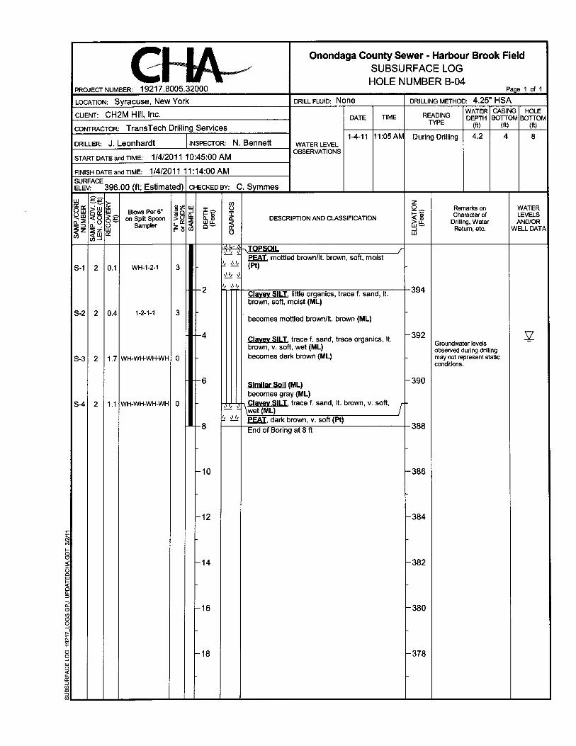
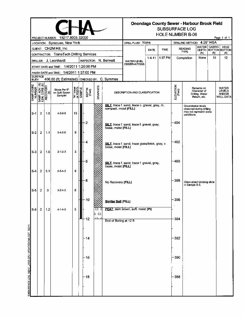
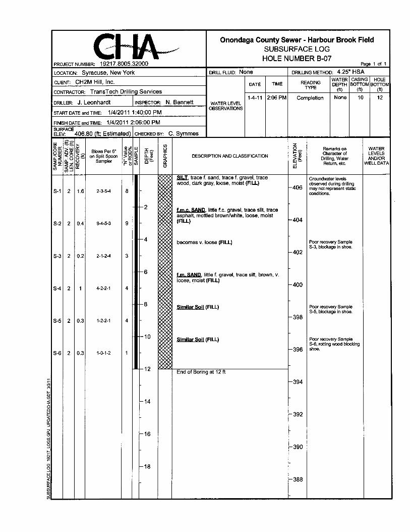
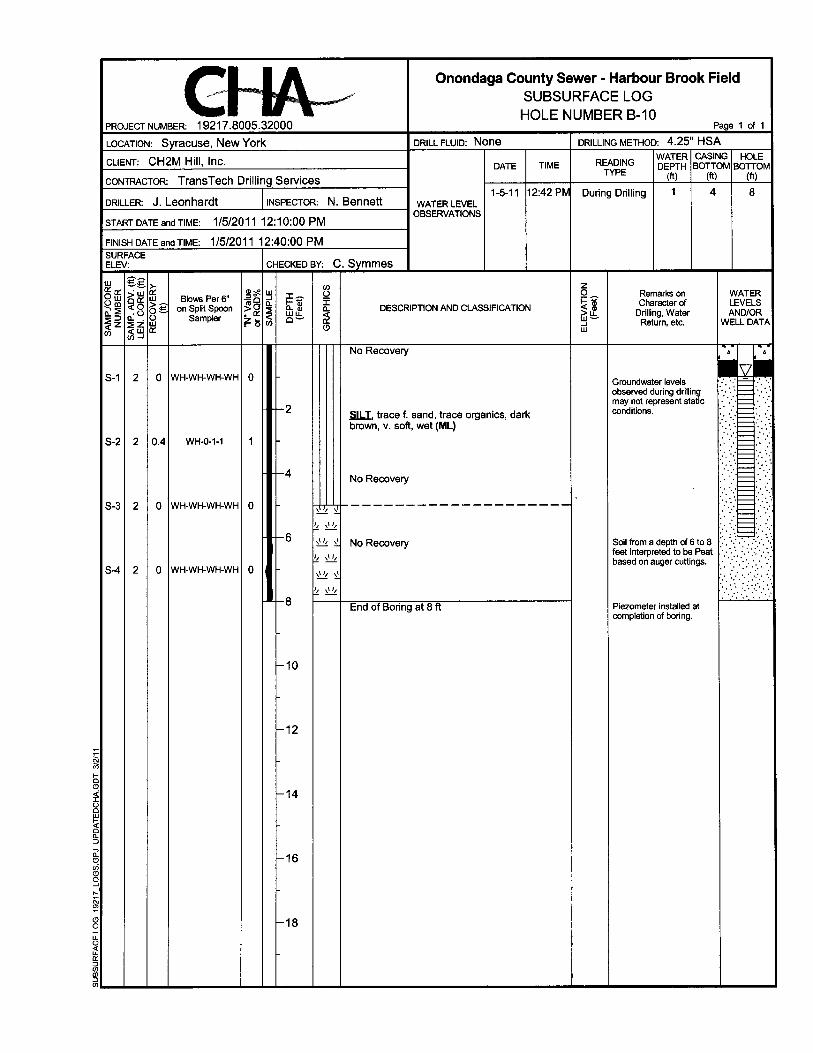
This memorandum summarizes the results of the geotechnical investigation performed for the combined sewer overflow (CSO) proposed in Harbour Brook Field located in Syracuse, New York. The project includes the installation of a Hydro International Storm King Overflow structure and construction of the associated outflow pipes. The objectives of this investigation were to identify subsurface conditions in the area of the CSO and outflow pipes and develop geotechnical recommendations for the design and construction of the proposed project. PROJECT AND SITE DESCRIPTION We understand that Onondaga County is planning to construct a CSO in Harbour Brook field, in the City of Syracuse, New York. The CSO will include a Hydro International Storm King Overflow with Swirl Cleanse tank and associated outfall pipes. In addition to the CSO construction, the County is planning a constructed wetland area in the northern portion of the site adjacent to Harbour Brook. This will include the construction of a number of soil containment berms with an approximate average height of six feet. The site is located off of West Onondaga Street, near the intersection with Velasko Road. The site is an open field with few large trees that slopes towards Harbour Brook and has existing subsurface sewer lines, evident by manholes at the ground surface. The site is bordered by Velasko Road to the west, apartment buildings to the east, West Onondaga Street to the south and Harbour Brook to the north. Existing monitoring wells were observed at the site during this investigation. CHA completed 16 borings and installed 8 monitoring wells for a wetland mitigation investigation on January 4 through January 5, 2011 in the areas bordering the north and south banks of Harbour Brook. The nearest of these borings (B-7) to the approximate proposed CSO structure location is about 150 feet to the north. Logs of these borings were submitted to the Environmental/Planning group on January 24, 2011 and are included herein for reference. The locations of these borings and monitoring wells are shown on the attached boring location plan.

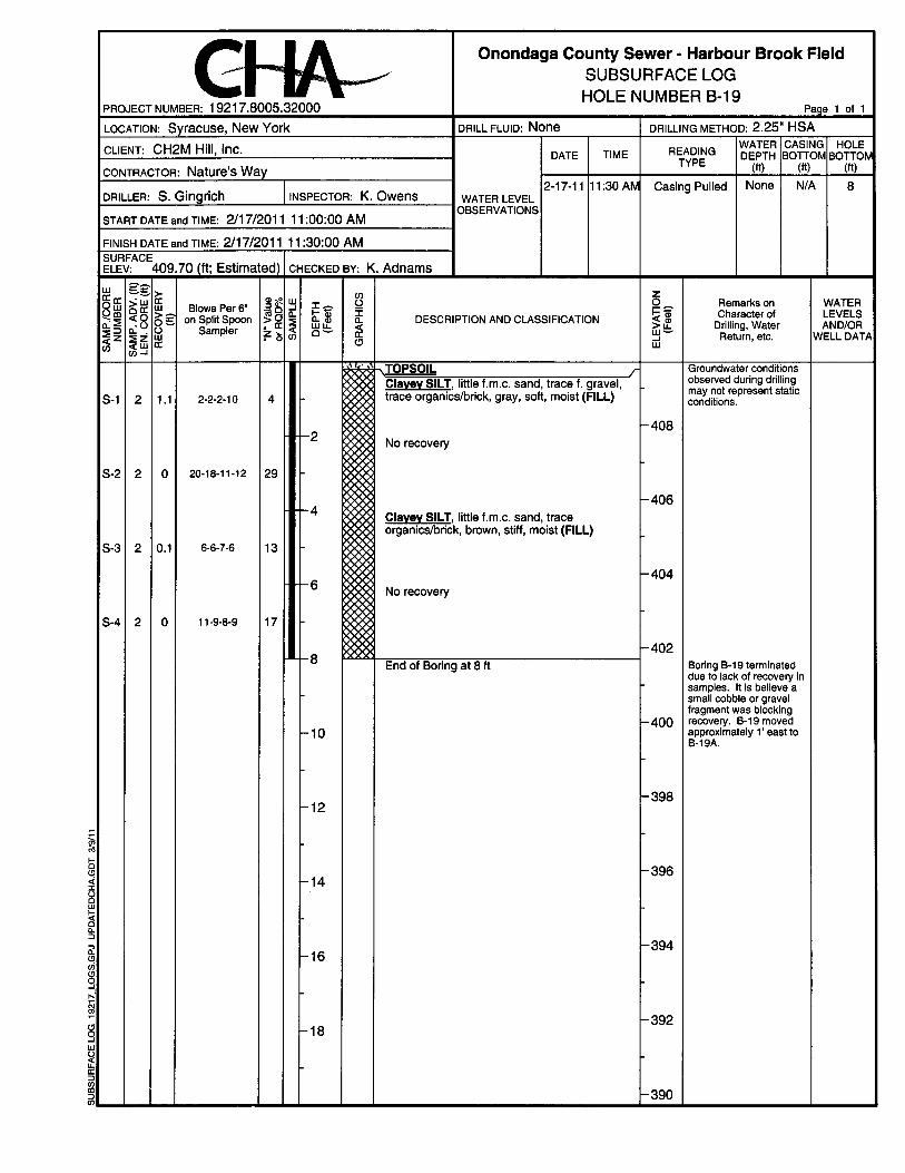
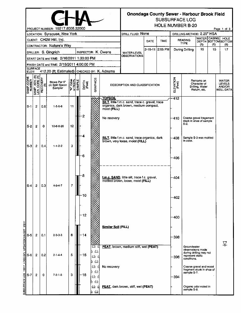
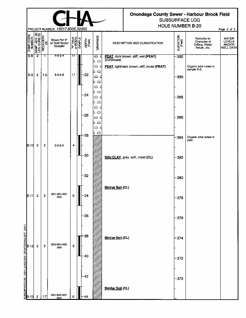
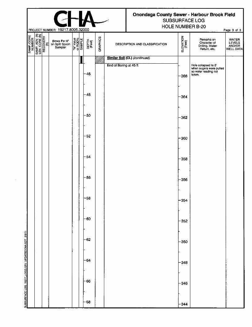
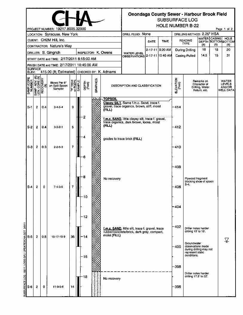
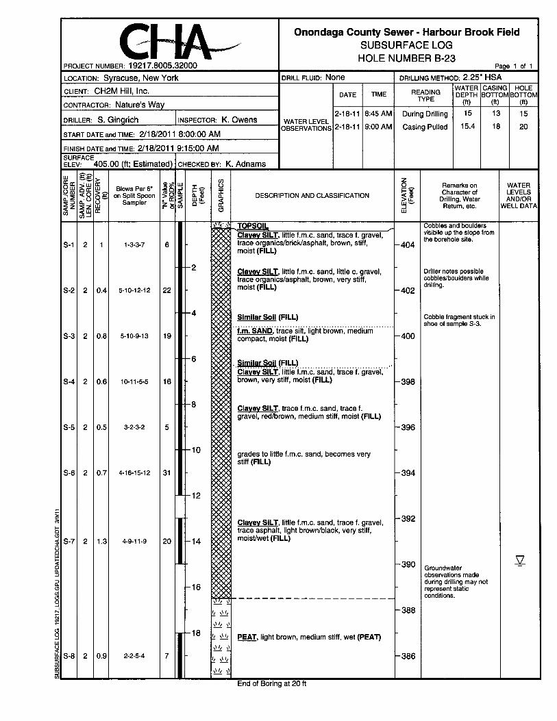
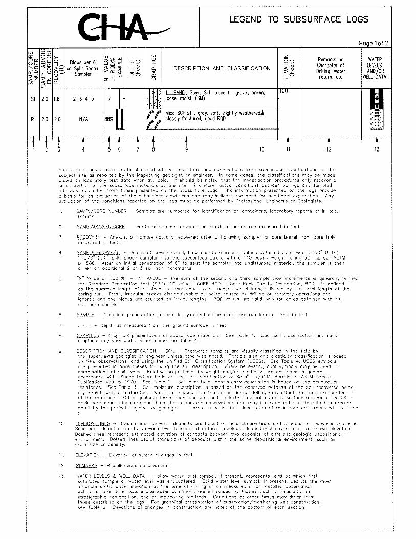
SUBSURFACE INVESTIGATION Eight borings were advanced and one piezometer was installed for this geotechnical investigation between February 16 and February 18, 2011 designated as B-17 through B-23 and B-19A. Borings B-17, B-18, B-19 and B-19A were advanced in the area of the proposed outfall pipe alignment. Borings B-20 through B-22 were advanced in the originally proposed area for the CSO unit, and boring B-23 was advanced on the slope north of Harbour Brook. Note that the proposed location for the CSO unit was revised after completion of the borings. The revised location is in the vicinity of B-18. The borings were located in the field by CHA during the subsurface investigation by measuring from existing features. Boring elevations were estimated from topographic survey mapping of the project site completed by CHA. The locations and elevations of the borings should be considered accurate only to the degree implied by the method used to determine them. The approximate boring locations are shown on the attached Boring Location Plan (Figure 1). The borings were advanced by Nature’s Way Environmental Construction & Consultants, Inc. of Crittenden, New York. A geotechnical engineer observed the field investigation to ensure proper drilling and sampling methods were used for this investigation, to classify soil samples, and to prepare field logs documenting subsurface conditions. The borings were advanced with a rubber-track mounted drill rig using 2¼” hollow stem augers (HSA). Split-spoon sampling and standard penetration tests were generally conducted in the borings continuously to depths varying from 6 to 12 feet and at standard 5-foot intervals to boring termination. In borings B-20 through B-22, continuous sampling was resumed at the anticipated bearing depth of the CSO tank. The split-spoon sampler was driven with a 140(±) pound hammer free falling 30(±) inches, in general accordance with ASTM International guidelines (ASTM D1586). “Blow counts” are recorded on the boring logs and indicate the penetration resistance for a six-inch advancement of the split-spoon sampler. Initially, the sampler is driven six inches to seat the sampler in undisturbed material. The number of blows required to drive the sampler the next twelve inches is taken as the standard penetration resistance or “N” value. This value is indicative of the soil’s in-place density or consistency. The final six-inch increment that the spoon is driven is not included in the determination of “N”. Refusal is defined as a resistance of greater than 50 blows per six inches of penetration. A temporary piezometer was installed in boring B-21 to provide a more accurate observation of the static groundwater level compared to water tables observed during drilling operations. SUBSURFACE CONDITIONS According to the Surficial Geologic Map of New York, Finger Lakes Sheet (Muller, E.H., et al., 1986) the site deposition consists of lacustrine silt and clay that is generally calcareous with potential land instability and variable thickness. According to the Geologic Map of New York, Finger Lakes Sheet (Rickard, L.V., Fisher, D.W., 1986) the bedrock is of the Syracuse Formation that consists of dolostone, shale, gypsum and salt. Subsurface conditions encountered in the borings for this investigation are detailed and described on the attached boring logs. General subsurface conditions are described below in order of increasing depth. It should be noted that subsurface conditions documented on the boring logs for the previous (January 4 through January 5, 2011) investigation at the site indicate similar soil types and layering exist in the northern portion of the site. Topsoil – Topsoil was encountered at ground surface in all borings to depths varying from 0.1 to 0.3 feet.

Fill – Fill was encountered beneath the topsoil in all borings to depths varying from 8 to 17.5 feet and to termination in boring B-19. The fill generally consisted of varying amounts of fine to coarse sand and clayey silt, and trace amounts of fine to coarse gravel. The fill also contained trace amounts of organics, brick, rubber fragments, concrete rubble, coal, glass, and asphalt. The fill was generally brown and visually classified as moist to wet. Based on SPT resistance penetration the fill was very loose to compact. Silt – Silt was encountered below the fill in borings B-17, B-18 and B-19A to depths ranging from 12.5 to 16.5 feet. The silt contained varying amounts of clay, fine to coarse sand, and fine gravel. The silt was gray/black; and the moisture content was observed to be moist to wet. Based on SPT resistance, the silt was soft to medium stiff. Sand – Fine to coarse sand was encountered beneath the fill in borings B-21 and B-22 to depths ranging from 22.5 to 25.5 feet. The sand contained of varying amounts of silt and clay with trace amounts of fine gravel. The sand was brown and the moisture content was visually classified as moist to wet. Based on SPT resistance, penetration the sand was very loose to medium compact. Peat – Peat was encountered beneath the silt, sand, or fill to depths varying from 28 to 33.3 feet in borings B-20 through B-22, and to termination in borings B-17, B-18, B-19, and B-23. The peat was brown and the moisture content was visually classified as moist to wet. Based on SPT resistance, the peat was soft to stiff. Silty Clay – Silty clay was encountered beneath the peat in borings B-20 through B-22 to termination. The silty clay was gray and the moisture content was visually classified as moist to wet. Based on SPT resistance penetration, the silty clay was very soft to soft. GROUNDWATER Groundwater level observations were made in the boreholes during drilling operations and within the piezometer that was installed in B-21 to determine static groundwater level. Groundwater levels are listed in Table 1 below.
Table 1 – Estimated Depth of Groundwater
Boring Estimated Depth to Groundwater (ft)
Estimated Elevation (ft)
B-18 8.7 397.8
B-19A 9.7 400.0
B-20 15.0 397.2
B-21 14.3* 401.7*
B-22 14.5 400.5
B-23 15.4 389.6
*Static groundwater level measured approximately 6 days after piezometer installation. Boreholes were only open for a short period of time. Due to the fine grained nature of the soil encountered at the site, water levels observed during drilling may not represent static groundwater level conditions. In addition, factors such as temperature and precipitation also affect groundwater levels. For these reasons, long-term groundwater levels may differ from those described herein at any given time. We recommend that a groundwater elevation of 402 feet be used for the design of the CSO structure.

RECOMMENDATIONS General Final design information for the CSO structure and outlet pipe construction, including structure depth, diameter, and location, as well as finished site grade, were not available at the time this memo was prepared. The recommendations provided in this report are based on preliminary design information and the understanding that no significant changes in site grade will be completed. Based on preliminary design information provided, we understand that the CSO will consist of a cast in place concrete structure with a tank depth of about 14 feet and an inside diameter of about 30 feet. The tank wall thickness is estimated to be 1.5 feet; and the base slab will be approximately 2 feet thick. The base slab will also extend about 2.5 foot from the outside tank wall face. The weight of the CSO structure and internal equipment is estimated to be approximately 923 kips. Based on a preliminary detail provided for the CSO structure, we understand that the top of the tank will be approximately at grade. CSO Structure Based on the preliminary design information and the subsurface information from borings B-18 through B-22, it is estimated that the base of the CSO structure will bear in the peat material, approximately 8 feet above the underlying silty clay surface. Note that B-18, which is the nearest boring to the proposed CSO location, did not fully penetrate the peat material. However, a bottom elevation of 384 feet for the peat at the proposed CSO location was interpolated from the information obtained from B-20 through B-22 since the bottom of this material appears to be relatively consistent at the locations investigated in this portion of the site. The peat material is not considered adequate for support of the CSO due to its high organic content and potential to decompose over time, therefore, it is recommended that the peat be removed below the CSO to the silty clay and replaced with structural fill as described in the Structural Fill Section and as shown on the attached Limits of Structural Fill Detail to create an acceptable bearing surface. The bearing surface shall be prepared in accordance with the Site Preparation Section included herein. Note that the site soils are considered moisture sensitive and may become unstable if exposed to precipitation; therefore, the structural fill shall be placed as soon as possible after excavation to protect these soils from excessive moisture. Based on this recommendation, the preliminary design information for the CSO, and subsurface conditions, we recommend that the CSO structure (full of liquid) be designed to a maximum un-factored contact pressure of 1.8 ksf on the prepared structural fill subgrade. Subsequently, the net increase in stress at the surface of the underlying very soft silty clay will be negligible with respect to existing conditions. This will eliminate the potential for appreciable settlement of the CSO structure. The walls of the CSO structure will retain earth and will be restrained against lateral movement; therefore they should be designed to resist “at rest” earth pressures. Given the groundwater conditions at the site, the CSO walls should also be designed to resist hydrostatic pressure behind the walls. Backfill around the structure should consist of structural fill that extends a distance from the structure walls at least half the structure wall height. The structure walls can then be designed based on the engineering properties of the structural fill as follows: • Total unit weight: 125 pcf • Buoyant unit weight: 65 pcf • Angle of internal friction: 32 degrees • Coefficient of at-rest earth pressure (Ko): 0.47

CSO Pipes Several pipes to carry flow to and from the CSO structure will be installed at the project site. These include a 30-inch diameter HDPE inlet pipe, an 8-inch diameter HDPE underflow pipe, a 6-inch diameter HDPE overspill pipe, and a 42-inch diameter HDPE overflow (outfall) pipe. Pipes sections will be connected using water-tight bell and spigot joints. The pipes will enter/exit the CSO structure at various elevations and from various directions; and will therefore be installed within the various soil types encountered in the borings. We recommend that soils encountered along pipe alignments be over-excavated by one half of the pipe diameter or a minimum of one foot and replaced with NYSDOT No. 2 crushed stone in order to provide a firm bedding surface for uniform pipe support. It is also recommended that a 6 oz./s.y. non-woven geotextile such as Mirafi 160N or equal be placed on the exposed soil surface prior to placing the crushed stone. Note that there is the potential for some differential vertical deflection of the CSO pipes over time due to the varying soil types (including peat) that will comprise the subgrade for pipes. The HDPE pipe material should accommodate potential differential vertical movement; however consideration should be given to pipe joint selection to minimize the risk for potential joint separation due to horizontal displacement of pipe sections that could result from differential vertical deflection of pipes. It is anticipated that the proposed water-tight bell and spigot pipe joints should provide adequate resistance to potential separation, however, the use of joint restraints should be considered to minimize the risk. To eliminate all risk of pipe joint separation, butt fused joints should be considered. Site Preparation The areas within the footprint of the proposed construction should be stripped of any vegetation and topsoil. Excavations, including undercuts, for the CSO structure and pipes shall be completed to the levels described in the CSO Structure and CSO Pipes Sections. Subsequent to stripping and excavating to proposed grades, the exposed subgrade should be proof rolled using a smooth drum roller with a gross weight of at least 10 tons. The roller should operate in its vibratory mode, and complete at least six passes over the subgrade at a speed not exceeding 3 feet per second (fps). Any areas which pump or weave during proof rolling should be undercut by a minimum of 12 inches and stabilized. If the vibratory roller tends to “bring up” moisture, the subgrade should be proof rolled with the roller operating in the static mode. A smaller roller or hand-operated compaction equipment shall be used in smaller, tight access areas as required. Excavations should then be brought to proposed bearing grades using compacted NYSDOT No. 2 crushed stone or structural fill as previously described herein. Structural fill should meet the gradation requirements and be compacted as indicated in the Structural Fill Section. Structural Fill Structural fill shall be used for backfilling the excavations and undercuts. Material suitable for structural fill should consist of sound, durable, sand and gravel, free of stumps, roots, other organics and any frozen or deleterious materials conforming to the following gradation:
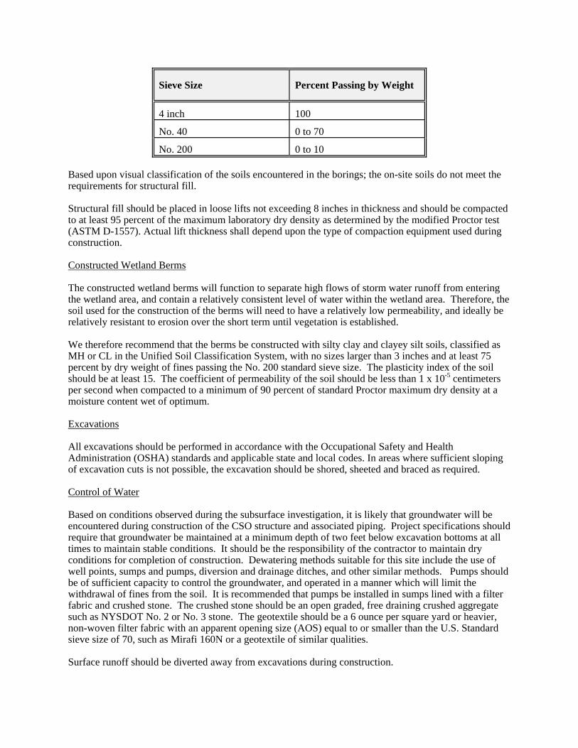
Sieve Size Percent Passing by Weight
4 inch 100
No. 40 0 to 70
No. 200 0 to 10 Based upon visual classification of the soils encountered in the borings; the on-site soils do not meet the requirements for structural fill. Structural fill should be placed in loose lifts not exceeding 8 inches in thickness and should be compacted to at least 95 percent of the maximum laboratory dry density as determined by the modified Proctor test (ASTM D-1557). Actual lift thickness shall depend upon the type of compaction equipment used during construction. Constructed Wetland Berms The constructed wetland berms will function to separate high flows of storm water runoff from entering the wetland area, and contain a relatively consistent level of water within the wetland area. Therefore, the soil used for the construction of the berms will need to have a relatively low permeability, and ideally be relatively resistant to erosion over the short term until vegetation is established. We therefore recommend that the berms be constructed with silty clay and clayey silt soils, classified as MH or CL in the Unified Soil Classification System, with no sizes larger than 3 inches and at least 75 percent by dry weight of fines passing the No. 200 standard sieve size. The plasticity index of the soil should be at least 15. The coefficient of permeability of the soil should be less than 1 x 10⁻⁵ centimeters per second when compacted to a minimum of 90 percent of standard Proctor maximum dry density at a moisture content wet of optimum. Excavations All excavations should be performed in accordance with the Occupational Safety and Health Administration (OSHA) standards and applicable state and local codes. In areas where sufficient sloping of excavation cuts is not possible, the excavation should be shored, sheeted and braced as required. Control of Water Based on conditions observed during the subsurface investigation, it is likely that groundwater will be encountered during construction of the CSO structure and associated piping. Project specifications should require that groundwater be maintained at a minimum depth of two feet below excavation bottoms at all times to maintain stable conditions. It should be the responsibility of the contractor to maintain dry conditions for completion of construction. Dewatering methods suitable for this site include the use of well points, sumps and pumps, diversion and drainage ditches, and other similar methods. Pumps should be of sufficient capacity to control the groundwater, and operated in a manner which will limit the withdrawal of fines from the soil. It is recommended that pumps be installed in sumps lined with a filter fabric and crushed stone. The crushed stone should be an open graded, free draining crushed aggregate such as NYSDOT No. 2 or No. 3 stone. The geotextile should be a 6 ounce per square yard or heavier, non-woven filter fabric with an apparent opening size (AOS) equal to or smaller than the U.S. Standard sieve size of 70, such as Mirafi 160N or a geotextile of similar qualities. Surface runoff should be diverted away from excavations during construction.
OBSERVATION DURING CONSTRUCTION A qualified geotechnical engineer should carefully inspect the final excavation and bearing surfaces to ascertain that the subgrade has been properly prepared and is consistent with the design recommendations. The inspection of subgrade and structural fill should include probing at select locations. Materials used as fill, including those used below structures, should be tested by a qualified soils laboratory to verify they meet the specified gradations and to determine their maximum dry density for compaction. In-place density tests should be performed to verify that compaction methods and equipment achieve the required densities. CONCLUSION The general geotechnical recommendations presented in this memo are based, in part, on project and subsurface information available at the time this report was prepared and in accordance with generally accepted foundation engineering practices. If changes are made to the locations of the proposed structures, a geotechnical engineer should confirm recommendations made herein. Additionally, some variation of subsurface conditions may occur from the locations explored that may not become evident until construction. Depending on the nature and extent of the variations, it may be necessary to re-evaluate the recommendations presented herein. Attachments V:\Projects\ANY\K2\19217\Reports\Geo\CSO Memo Final.docx


SUMMARY PAGE 1 OF 1 8/17/11 CHA PROJECT NO. 19217 L:\WP\19217\Compensatory\01100 Summary.DOC SECTION 01100
SECTION 01100 - SUMMARY
PART 1 - GENERAL
1.1 RELATED DOCUMENTS
A. Drawings and general provisions of the Contract, including General and Supplementary Conditions and other Division 1 Specification Sections, apply to this Section.
1.2 WORK COVERED BY CONTRACT DOCUMENTS
A. Project Identification: Project consists of Compensatory Storage Excavation Project.
1. Project Location: The project is located along Harbor Brook between Velasko Road and Holden Street in the City of Syracuse, New York.
2. Owner: Onondaga County.
B. Engineer Identification: The Contract Documents, dated August 12, 2011, were prepared for Project by CHA Consulting, Inc. 441 South Salina Street, Syracuse, NY 13202.
C. The Work consists of the excavation of compensatory storage areas on the site; stockpiling 5,800 CY of suitable material on site for future use; the removal of all unsuitable and excess material; installation of temporary seed and mulch; and the installation of permanent seed and mulch in the Spring of 2012.
1.3 CONTRACT
A. Project will be constructed under a general construction contract.
1.4 FUTURE WORK
A. Future Contract: Owner will award a separate contract for additional work to be performed at the site after Substantial Completion. Completion of that work will depend on successful completion of preparatory work under this Contract. The Contract for future work will include the construction of a constructed Wetlands Pilot Treatment System.
PART 2 - PRODUCTS (Not Used)
PART 3 - EXECUTION (Not Used)
END OF SECTION 01100


WORK RESTRICTIONS PAGE 1 OF 1 8/17/11 CHA PROJECT NO. 19217 L:\WP\19217\Compensatory\01140 Work Restrictions.DOC SECTION 01140
SECTION 01140 - WORK RESTRICTIONS
PART 1 - GENERAL
1.1 RELATED DOCUMENTS
A. Drawings and general provisions of the Contract, including General and Supplementary Conditions and other Division 1 Specification Sections, apply to this Section.
1.2 USE OF PREMISES
A. Use of Site: Limit use of premises to work in areas indicated. Do not disturb portions of site beyond areas in which the Work is indicated.
1. Driveways and Entrances: Keep driveways and entrances serving premises clear and available to Owner, Owner's employees, and emergency vehicles at all times. Do not use these areas for parking or storage of materials.
2. Work on site shall be limited to 7 a.m. to 6 p.m. Monday thru Saturday. Construction on Sunday is prohibited.
PART 2 - PRODUCTS (Not Used)
PART 3 - EXECUTION (Not Used)
END OF SECTION 01140


CONTRACT MODIFICATION PROCEDURES PAGE 1 OF 2 8/17/11 CHA PROJECT NO. 19217 L:\WP\19217\Compensatory\01250 Contract Modification Procedures.DOC SECTION 01250
SECTION 01250 - CONTRACT MODIFICATION PROCEDURES
PART 1 - GENERAL
1.1 RELATED DOCUMENTS
A. Drawings and general provisions of the Contract, including General and Supplementary Conditions and other Division 1 Specification Sections, apply to this Section.
1.2 SUMMARY
A. This Section specifies administrative and procedural requirements for handling and processing Contract modifications.
1.3 MINOR CHANGES IN THE WORK
A. Engineer will issue supplemental instructions authorizing Minor Changes in the Work, not involving adjustment to the Contract Sum or the Contract Time.
1.4 PROPOSAL REQUESTS
A. Owner-Initiated Proposal Requests: Engineer will issue a detailed description of proposed changes in the Work that may require adjustment to the Contract Sum or the Contract Time. If necessary, the description will include supplemental or revised Drawings and Specifications.
1. Proposal Requests issued by Engineer are for information only. Do not consider them instructions either to stop work in progress or to execute the proposed change.
2. Within time specified in Proposal Request after receipt of Proposal Request, submit a quotation estimating cost adjustments to the Contract Sum and the Contract Time necessary to execute the change.
a. Include a list of quantities of products required or eliminated and unit costs, with total amount of purchases and credits to be made. If requested, furnish survey data to substantiate quantities.
b. Indicate applicable taxes, delivery charges, equipment rental, and amounts of trade discounts.
c. Include an updated Contractor's Construction Schedule that indicates the effect of the change, including, but not limited to, changes in activity duration, start and finish times, and activity relationship. Use available total float before requesting an extension of the Contract Time.
B. Contractor-Initiated Proposals: If latent or unforeseen conditions require modifications to the Contract, Contractor may propose changes by submitting a request for a change to Engineer.
1. Include a statement outlining reasons for the change and the effect of the change on the Work. Provide a complete description of the proposed change. Indicate the effect of the proposed change on the Contract Sum and the Contract Time.
CONTRACT MODIFICATION PROCEDURES PAGE 2 OF 2 8/17/11 CHA PROJECT NO. 19217 L:\WP\19217\Compensatory\01250 Contract Modification Procedures.DOC SECTION 01250
2. Include a list of quantities of products required or eliminated and unit costs, with total amount of purchases and credits to be made. If requested, furnish survey data to substantiate quantities.
3. Indicate applicable taxes, delivery charges, equipment rental, and amounts of trade discounts.
4. Include an updated Contractor's Construction Schedule that indicates the effect of the change, including, but not limited to, changes in activity duration, start and finish times, and activity relationship. Use available total float before requesting an extension of the Contract Time.
C. Proposal Request Form: For Change Order proposals, use CSI Change Order Request (proposal format). A sample copy is included at end of this Section.
1.5 ALLOWANCES
A. Submit claims for increased costs because of a change in scope or nature of the allowance described in the Contract Documents, whether for the Purchase Order amount or Contractor's handling, labor, installation, overhead, and profit. Submit claims within 14 days of receipt of the Change Order or Construction Change Directive authorizing work to proceed. Owner will reject claims submitted later than 14 days after such authorization.
1.6 CHANGE ORDER PROCEDURES
A. On Owner's approval of a Proposal Request, Engineer will issue a Change Order for signatures of Owner and Contractor on form included at end of Part 3.
1.7 WORK CHANGE DIRECTIVE
A. Work Change Directive: Engineer may issue a Work Change Directive on form included at end of Part 3. Work Change Directive instructs Contractor to proceed with a change in the Work, for subsequent inclusion in a Change Order.
1. Work Change Directive contains a complete description of change in the Work. It also designates method to be followed to determine change in the Contract Sum or the Contract Time.
B. Documentation: Maintain detailed records on a time and material basis of work required by the Work Change Directive.
1. After completion of change, submit an itemized account and supporting data necessary to substantiate cost and time adjustments to the Contract.
PART 2 - PRODUCTS (Not Used)
PART 3 - EXECUTION (Not Used)
END OF SECTION 01250
PAYMENT PROCEDURES PAGE 1 OF 4 8/17/11 CHA PROJECT NO. 19217 L:\WP\19217\Compensatory\01290 Payment Procedures.DOC SECTION 01290
SECTION 01290 - PAYMENT PROCEDURES
PART 1 - GENERAL
1.1 RELATED DOCUMENTS
A. Drawings and general provisions of the Contract, including General and Supplementary Conditions and other Division 1 Specification Sections, apply to this Section.
1.2 SUMMARY
A. This Section specifies administrative and procedural requirements necessary to prepare and process Applications for Payment.
1.3 DEFINITIONS
A. Schedule of Values: A statement furnished by Contractor allocating portions of the Contract Sum to various portions of the Work and used as the basis for reviewing Contractor's Applications for Payment.
1.4 SCHEDULE OF VALUES
A. Coordination: Coordinate preparation of the Schedule of Values with preparation of Contractor's Construction Schedule.
1. Submit the Schedule of Values to Engineer at earliest possible date but no later than 21 days before the date scheduled for submittal of initial Applications for Payment.
B. Format and Content: Use the Project Manual table of contents as a guide to establish line items for the Schedule of Values. Provide at least one line item for each Specification Section.
1. Identification: Include the following Project identification on the Schedule of Values:
a. Project name and location. b. Name of Engineer. c. Project number. d. Contractor's name and address. e. Date of submittal.
2. Provide a breakdown of the Contract Sum in enough detail to facilitate continued evaluation of Applications for Payment and progress reports. Coordinate with the Project Manual table of contents. Provide several line items for principal subcontract amounts, where appropriate.
3. Round amounts to nearest whole dollar; total shall equal the Contract Sum.
4. Each item in the Schedule of Values and Applications for Payment shall be complete. Include total cost and proportionate share of general overhead and profit for each item.
5. Schedule Updating: Update and resubmit the Schedule of Values before the next Applications for Payment when Change Orders or Construction Change Directives result in a change in the Contract Sum.

PAYMENT PROCEDURES PAGE 2 OF 4 8/17/11 CHA PROJECT NO. 19217 L:\WP\19217\Compensatory\01290 Payment Procedures.DOC SECTION 01290
1.5 APPLICATIONS FOR PAYMENT
A. Each Application for Payment shall be consistent with previous applications and payments as certified by Engineer and paid for by Owner.
1. Initial Application for Payment, Application for Payment at time of Substantial Completion, and final Application for Payment involve additional requirements.
B. Payment Application Times: The date for each progress payment is indicated in the Agreement between Owner and Contractor. The period of construction Work covered by each Application for Payment is the period indicated in the Agreement.
C. Payment Application Times: The date for each progress payment is the 15th day of each month. The period covered by each Application for Payment starts on the day following the end of the preceding period and ends 15 days before the date for each progress payment.
D. Payment Application Forms: Use AIA Document G702 and AIA Document G703 Continuation Sheets or EJCDC D rm for Applications for Payment.
E. Application Preparation: Complete every entry on form. Notarize and execute by a person authorized to sign legal documents on behalf of Contractor. Engineer will return incomplete applications without action.
1. Entries shall match data on the Schedule of Values and Contractor's Construction Schedule. Use updated schedules if revisions were made.
2. Include amounts of Change Orders and Construction Change Directives issued before last day of construction period covered by application.
F. Transmittal: Submit 3 signed and notarized original copies of each Application for Payment to Engineer by a method ensuring receipt within 24 hours. One copy shall include waivers of lien and similar attachments if required.
1. Transmit each copy with a transmittal form listing attachments and recording appropriate information about application.
G. Waivers of Mechanic's Lien: With each Application for Payment, submit waivers of mechanic's lien from every entity who is lawfully entitled to file a mechanic's lien arising out of the Contract and related to the Work covered by the payment.
1. Submit partial waivers on each item for amount requested, before deduction for retainage, on each item.
2. When an application shows completion of an item, submit final or full waivers.
3. Owner reserves the right to designate which entities involved in the Work must submit waivers.
4. Waiver Delays: Submit each Application for Payment with Contractor's waiver of mechanic's lien for construction period covered by the application.
a. Submit final Application for Payment with or preceded by final waivers from every entity involved with performance of the Work covered by the application who is lawfully entitled to a lien.
PAYMENT PROCEDURES PAGE 3 OF 4 8/17/11 CHA PROJECT NO. 19217 L:\WP\19217\Compensatory\01290 Payment Procedures.DOC SECTION 01290
5. Waiver Forms: Submit waivers of lien on forms, executed in a manner acceptable to Owner.
H. Initial Application for Payment: Administrative actions and submittals that must precede or coincide with submittal of first Application for Payment include the following:
1. List of subcontractors. 2. Schedule of Values. 3. Contractor's Construction Schedule (preliminary if not final). 4. Submittals Schedule (preliminary if not final). 5. List of Contractor's staff assignments. 6. Certificates of insurance and insurance policies.
I. Application for Payment at Substantial Completion: After issuing the Certificate of Substantial Completion, submit an Application for Payment showing 100 percent completion for portion of the Work claimed as substantially complete.
1. Include documentation supporting claim that the Work is substantially complete and a statement showing an accounting of changes to the Contract Sum.
2. This application shall reflect Certificates of Partial Substantial Completion issued previously for Owner occupancy of designated portions of the Work.
J. Final Payment Application: Submit final Application for Payment with releases and supporting documentation not previously submitted and accepted, including, but not limited, to the following:
1. Evidence of completion of Project closeout requirements.
2. Insurance certificates for products and completed operations where required and proof that taxes, fees, and similar obligations were paid.
3. Updated final statement, accounting for final changes to the Contract Sum.
4. AIA Document G706, "Contractor's Affidavit of Payment of Debts and Claims."
5. AIA Document G706A, "Contractor's Affidavit of Release of Liens."
6. AIA Document G707, "Consent of Surety to Final Payment."
7. Evidence that claims have been settled.
8. Final meter readings for utilities, a measured record of stored fuel, and similar data as of date of Substantial Completion or when Owner took possession of and assumed responsibility for corresponding elements of the Work.
9. Final, liquidated damages settlement statement.

PAYMENT PROCEDURES PAGE 4 OF 4 8/17/11 CHA PROJECT NO. 19217 L:\WP\19217\Compensatory\01290 Payment Procedures.DOC SECTION 01290
PART 2 - PRODUCTS (Not Used)
PART 3 - EXECUTION (Not Used)
END OF SECTION 01290

CONSTRUCTION PROGRESS DOCUMENTATION PAGE 1 OF 7 8/17/11 CHA PROJECT NO. 19217 L:\WP\19217\Compensatory\01320 Construction Progress Documentation.DOC SECTION 01320
SECTION 01320 - CONSTRUCTION PROGRESS DOCUMENTATION
PART 1 - GENERAL
1.1 RELATED DOCUMENTS
A. Drawings and general provisions of the Contract, including General and Supplementary Conditions and other Division 1 Specification Sections, apply to this Section.
1.2 SUMMARY
A. This Section includes administrative and procedural requirements for documenting the progress of construction during performance of the Work, including the following:
1. Contractor's Construction Schedule. 2. Submittals Schedule. 3. Daily construction reports. 4. Material location reports. 5. Field condition reports. 6. Special reports. 7. Construction photographs.
1.3 DEFINITIONS
A. Activity: A discrete part of a project that can be identified for planning, scheduling, monitoring, and controlling the construction project. Activities included in a construction schedule consume time and resources.
1. Critical activities are activities on the critical path. They must start and finish on the planned early start and finish times.
2. Predecessor activity is an activity that must be completed before a given activity can be started.
B. CPM: Critical path method, which is a method of planning and scheduling a construction project where activities are arranged based on activity relationships. Network calculations determine when activities can be performed and the critical path of Project.
C. Critical Path: The longest continuous chain of activities through the network schedule that establishes the minimum overall Project duration and contains no float.
D. Event: The starting or ending point of an activity.
E. Float: The measure of leeway in starting and completing an activity.
1. Float time is not for the exclusive use or benefit of either Owner or Contractor, but is a jointly owned, expiring Project resource available to both parties as needed to meet schedule milestones and Contract completion date.
2. Free float is the amount of time an activity can be delayed without adversely affecting the early start of the following activity.

CONSTRUCTION PROGRESS DOCUMENTATION PAGE 2 OF 7 8/17/11 CHA PROJECT NO. 19217 L:\WP\19217\Compensatory\01320 Construction Progress Documentation.DOC SECTION 01320
3. Total float is the measure of leeway in starting or completing an activity without adversely affecting the planned Project completion date.
F. Fragnet: A partial or fragmentary network that breaks down activities into smaller activities for greater detail.
G. Major Area: A story of construction, a separate building, or a similar significant construction element.
H. Milestone: A key or critical point in time for reference or measurement.
I. Network Diagram: A graphic diagram of a network schedule, showing activities and activity relationships.
1.4 SUBMITTALS
A. Qualification Data: For firms and persons specified in "Quality Assurance" Article and in-house scheduling personnel to demonstrate their capabilities and experience. Include lists of completed projects with project names and addresses, names and addresses of architects and owners, and other information specified.
B. Submittals Schedule: Submit 3 copies of schedule. Arrange the following information in a tabular format:
1. Scheduled date for first submittal. 2. Specification Section number and title. 3. Submittal category (action or informational). 4. Name of subcontractor. 5. Description of the Work covered. 6. Scheduled date for Engineer's final release or approval.
C. Contractor's Construction Schedule: Submit 3 printed copies of initial schedule, one a reproducible print and one a blue- or black-line print, large enough to show entire schedule for entire construction period.
1. Submit an electronic copy of schedule on CD or DVD. Include type of schedule (Initial or Updated) and date on label.
D. Construction Photographs: Submit a digital photo of each view within 7 days of taking photographs.
1. Format: Digital JPG image with minimum resolution of 2584x1936 and image quality set to fine/high or better.
2. Identification: A photo-log shall be provided containing a record for each submitted photo with the following information:
a. File Name of Photo.
b. Name of Project.
c. Name and address of photographer.
d. Name of Engineer.

CONSTRUCTION PROGRESS DOCUMENTATION PAGE 3 OF 7 8/17/11 CHA PROJECT NO. 19217 L:\WP\19217\Compensatory\01320 Construction Progress Documentation.DOC SECTION 01320
e. Name of Contractor.
f. Date photograph was taken.
g. Description of vantage point, indicating location, direction (by compass point), and elevation or story of construction.
3. Digital Images: Submit a complete set of digital image electronic files and a Project Record Document. Identify electronic media with date photographs were taken. Submit images that have the same aspect ratio as the sensor, uncropped.
E. Daily Construction Reports: Submit 2 copies at monthly intervals.
F. Field Condition Reports: Submit 2 copies at time of discovery of differing conditions.
G. Special Reports: Submit 2 copies at time of unusual event.
1.5 QUALITY ASSURANCE
A. Scheduling Consultant Qualifications: An experienced specialist in CPM scheduling and reporting.
B. Photographer Qualifications: An individual of established reputation who has been regularly engaged as a professional photographer for not less than three years.
1.6 COORDINATION
A. Coordinate preparation and processing of schedules and reports with performance of construction activities and with scheduling and reporting of separate contractors.
B. Coordinate Contractor's Construction Schedule with the Schedule of Values, list of subcontracts, Submittals Schedule, progress reports, payment requests, and other required schedules and reports.
1. Secure time commitments for performing critical elements of the Work from parties involved.
2. Coordinate each construction activity in the network with other activities and schedule them in proper sequence.
C. Auxiliary Services: Cooperate with photographer and provide auxiliary services requested, including access to Project site and use of temporary facilities including temporary lighting.
PART 2 - PRODUCTS
2.1 SUBMITTALS SCHEDULE
A. Preparation: Submit a schedule of submittals, arranged in chronological order by dates required by construction schedule. Include time required for review, resubmittal, ordering, manufacturing, fabrication, and delivery when establishing dates.
1. Coordinate Submittals Schedule with list of subcontracts, the Schedule of Values, and Contractor's Construction Schedule.

CONSTRUCTION PROGRESS DOCUMENTATION PAGE 4 OF 7 8/17/11 CHA PROJECT NO. 19217 L:\WP\19217\Compensatory\01320 Construction Progress Documentation.DOC SECTION 01320
2.2 CONTRACTOR'S CONSTRUCTION SCHEDULE, GENERAL
A. Procedures: Comply with procedures contained in AGC's "Construction Planning & Scheduling."
B. Time Frame: Extend schedule from date established for the Notice of Award to date of Final Completion.
1. Contract completion date shall not be changed by submission of a schedule that shows an early completion date, unless specifically authorized by Change Order.
C. Activities: Treat each story or separate area as a separate numbered activity for each principal element of the Work. Comply with the following:
1. Activity Duration: Define activities so no activity is longer than 21 days, unless specifically allowed by Engineer.
2. Procurement Activities: Include procurement process activities for long lead items and major items, requiring a cycle of more than 60 days, as separate activities in schedule. Procurement cycle activities include, but are not limited to, submittals, approvals, purchasing, fabrication, and delivery.
3. Submittal Review Time: Include review and resubmittal times indicated in Division 1 Section "Submittal Procedures" in schedule. Coordinate submittal review times in Contractor's Construction Schedule with Submittals Schedule.
4. Startup and Testing Time: Include not less than 14 days for startup and testing.
5. Substantial Completion: Indicate completion in advance of date established for Substantial Completion, and allow time for Engineer's administrative procedures necessary for certification of Substantial Completion.
D. Constraints: Include constraints and work restrictions indicated in the Contract Documents and as follows in schedule, and show how the sequence of the Work is affected.
1. Phasing: Arrange list of activities on schedule by phase.
2. Work under More Than One Contract: Include a separate activity for each contract.
3. Work by Owner: Include a separate activity for each portion of the Work performed by Owner.
4. Work Restrictions: Show the effect of the following items on the schedule:
a. Coordination with existing construction. b. Limitations of continued occupancies. c. Uninterruptible services. d. Partial occupancy before Substantial Completion. e. Use of premises restrictions. f. Provisions for future construction. g. Seasonal variations. h. Environmental control.
5. Work Stages: Indicate important stages of construction for each major portion of the Work, including, but not limited to, the following:

CONSTRUCTION PROGRESS DOCUMENTATION PAGE 5 OF 7 8/17/11 CHA PROJECT NO. 19217 L:\WP\19217\Compensatory\01320 Construction Progress Documentation.DOC SECTION 01320
a. Subcontract awards. b. Submittals. c. Purchases. d. Fabrication. e. Sample testing. f. Deliveries. g. Installation. h. Tests and inspections. i. Adjusting. j. Curing. k. Startup and placement into final use and operation.
6. Area Separations: Identify each major area of construction for each major portion of the Work. Indicate where each construction activity within a major area must be sequenced or integrated with other construction activities to provide for the following:
a. Structural completion. b. Completion of electrical installation. c. Substantial Completion.
E. Milestones: Include milestones indicated in the Contract Documents in schedule, including, but not limited to the Notice to Proceed, Substantial Completion, and Final Completion.
F. Cost Correlation: At the head of schedule, provide a cost correlation line, indicating planned and actual costs. On the line, show dollar volume of the Work performed as of dates used for preparation of payment requests.
G. Contract Modifications: For each proposed contract modification and concurrent with its submission, prepare a time-impact analysis using fragnets to demonstrate the effect of the proposed change on the overall project schedule.
2.3 CONTRACTOR'S CONSTRUCTION SCHEDULE (GANTT CHART)
A. Gantt-Chart Schedule: Submit a comprehensive, fully developed, horizontal Gantt-chart-type, Contractor's Construction Schedule within 30 days of date established for the Notice of Award.
B. Preparation: Indicate each significant construction activity separately. Identify first workday of each week with a continuous vertical line.
1. For construction activities that require 2 months or longer to complete, indicate an estimated completion percentage in 10 percent increments within time bar.
2.4 REPORTS
A. Daily Construction Reports: Prepare a daily construction report recording the following information concerning events at Project site:
1. List of subcontractors at Project site. 2. List of separate contractors at Project site. 3. Approximate count of personnel at Project site. 4. High and low temperatures and general weather conditions. 5. Accidents. 6. Meetings and significant decisions. 7. Unusual events (refer to special reports). 8. Stoppages, delays, shortages, and losses.

CONSTRUCTION PROGRESS DOCUMENTATION PAGE 6 OF 7 8/17/11 CHA PROJECT NO. 19217 L:\WP\19217\Compensatory\01320 Construction Progress Documentation.DOC SECTION 01320
9. Emergency procedures. 10. Orders and requests of authorities having jurisdiction. 11. Change Orders received and implemented. 12. Work Change Directives received. 13. Service connected and disconnected. 14. Equipment or system tests and startups. 15. Partial Completions and occupancies. 16. Substantial Completions authorized.
B. Material Location Reports: At monthly intervals, prepare a comprehensive list of materials delivered to and stored at Project site. List shall be cumulative, showing materials previously reported plus items recently delivered. Include with lit a statement of progress on and delivery dates for materials or items of equipment fabricated or stored away from Project site.
C. Field Condition Reports: Immediately on discovery of a difference between field conditions and the Contract Documents, prepare a detailed report. Submit with a request for information on CSI Form 13.2A. Include a detailed description of the differing conditions, together with recommendations for changing the Contract Documents.
2.5 SPECIAL REPORTS
A. General: Submit special reports directly to Owner within one day of an occurrence. Distribute copies of report to parties affected by the occurrence.
B. Reporting Unusual Events: When an event of an unusual and significant nature occurs at Project site, whether or not related directly to the Work, prepare and submit a special report. List chain of events, persons participating, response by Contractor’s personnel, evaluation of results or effects, and similar pertinent information. Advise Owner in advance when these events are known or predictable.
PART 3 - EXECUTION
3.1 CONTRACTOR'S CONSTRUCTION SCHEDULE
A. Scheduling Consultant: Engage a consultant to provide planning, evaluation, and reporting using CPM scheduling.
1. In-House Option: Owner may waive the requirement to retain a consultant if Contractor employs skilled personnel with experience in CPM scheduling and reporting techniques. Submit qualifications.
2. Meetings: Scheduling consultant shall attend all meetings related to Project progress, alleged delays, and time impact.
B. Contractor's Construction Schedule Updating: At monthly intervals, update schedule to reflect actual construction progress and activities. Issue schedule 1 week before each regularly scheduled progress meeting.
1. Revise schedule immediately after each meeting or other activity where revisions have been recognized or made. Issue updated schedule concurrently with the report of each such meeting.
2. Include a report with updated schedule that indicates every change, including, but not limited to, changes in logic, durations, actual starts and finishes, and activity durations.

CONSTRUCTION PROGRESS DOCUMENTATION PAGE 7 OF 7 8/17/11 CHA PROJECT NO. 19217 L:\WP\19217\Compensatory\01320 Construction Progress Documentation.DOC SECTION 01320
3. As the Work progresses, indicate Actual Completion percentage for each activity.
C. Distribution: Distribute copies of approved schedule to Engineer, Owner, separate contractors, testing and inspecting agencies, and other parties identified by Contractor with a need-to-know schedule responsibility.
1. Post copies in Project meeting rooms and temporary field offices.
2. When revisions are made, distribute updated schedules to the same parties and post in the same locations. Delete parties from distribution when they have completed their assigned portion of the Work and are no longer involved in performance of construction activities.
3.2 CONSTRUCTION PHOTOGRAPHS
A. Photographer: Engage a qualified commercial photographer to take construction photographs.
B. Date Stamp: Unless otherwise indicated, date and time stamp each photograph as it is being taken so stamp is integral to photograph.
C. Preconstruction Photographs: Before starting construction, take color photographs of Project site and surrounding properties from different vantage points, as directed by Engineer. Show existing conditions adjacent to property.
D. Periodic Construction Photographs: Take 4 color photographs monthly, coinciding with cutoff date associated with each Application for Payment. Photographer shall select vantage points to best show status of construction and progress since last photographs were taken.
1. Field Office Prints: Retain an electronic set of photographs in field office at Project site, available at all times for reference. Identify photographs the same as for those submitted to Engineer.
E. Final Completion Construction Photographs: Take color photographs after date of Substantial Completion for submission as Project Record Documents. Engineer will direct photographer for desired vantage points.
END OF SECTION 01320


SUBMITTAL PROCEDURES PAGE 1 OF 7 8/17/11 CHA PROJECT NO. 19217 L:\WP\19217\Compensatory\01330 Submittal Procedures.DOC SECTION 01330
SECTION 01330 - SUBMITTAL PROCEDURES
PART 1 - GENERAL
1.1 RELATED DOCUMENTS
A. Drawings and general provisions of the Contract, including General and Supplementary Conditions and other Division 1 Specification Sections, apply to this Section.
1.2 SUMMARY
A. This Section includes administrative and procedural requirements for submitting Shop Drawings, Product Data, Samples, and other miscellaneous submittals.
1.3 DEFINITIONS
A. Action Submittals: Written and graphic information that requires Engineer's responsive action.
B. Informational Submittals: Written information that does not require Engineer's approval. Submittals may be rejected for not complying with requirements.
1.4 SUBMITTAL PROCEDURES
A. General: Electronic copies of CAD Drawings of the Contract Drawings will be provided by Engineer for Contractor's use in preparing submittals.
B. Coordination: Coordinate preparation and processing of submittals with performance of construction activities.
1. Coordinate each submittal with fabrication, purchasing, testing, delivery, other submittals, and related activities that require sequential activity.
2. Coordinate transmittal of different types of submittals for related parts of the Work so processing will not be delayed because of need to review submittals concurrently for coordination.
a. Engineer reserves the right to withhold action on a submittal requiring coordination with other submittals until related submittals are received.
C. Processing Time: Allow enough time for submittal review, including time for resubmittals, as follows. Time for review shall commence on Construction Manager's receipt of submittal.
1. Initial Review: Allow 14 days for initial review of each submittal. Allow additional time if processing must be delayed to permit coordination with subsequent submittals. Engineer will advise Contractor when a submittal being processed must be delayed for coordination.
D. Identification: Place a permanent label or title block on each submittal for identification.
1. Indicate name of firm or entity that prepared each submittal on label or title block.
SUBMITTAL PROCEDURES PAGE 2 OF 7 8/17/11 CHA PROJECT NO. 19217 L:\WP\19217\Compensatory\01330 Submittal Procedures.DOC SECTION 01330
2. Provide a space approximately 4 by 5 inches on label or beside title block to record Contractor's review and approval markings and action taken by Engineer.
3. Include the following information on label for processing and recording action taken:
a. Project name. b. Date. c. Name and address of Engineer. d. Name and address of Contractor. e. Name and address of subcontractor. f. Name and address of supplier. g. Name of manufacturer. h. Unique identifier, including revision number. i. Number and title of appropriate Specification Section. j. Drawing number and detail references, as appropriate. k. Other necessary identification.
E. Deviations: Highlight, encircle, or otherwise identify deviations from the Contract Documents on submittals.
F. Transmittal: Package each submittal individually and appropriately for transmittal and handling. Transmit each submittal using a transmittal form. Engineer will disregard submittals received from sources other than Contractor.
1. Transmittal Form: Use CSI Form 12.1A. A sample form is included at the end of this Section.
G. Distribution: Furnish copies of final submittals to manufacturers, subcontractors, suppliers, fabricators, installers, authorities having jurisdiction, and others as necessary for performance of construction activities. Show distribution on transmittal forms.
H. Use for Construction: Use only final submittals with mark indicating action taken by Engineer in connection with construction.
PART 2 - PRODUCTS
2.1 ACTION SUBMITTALS
A. General: Prepare and submit Action Submittals required by individual Specification Sections.
1. Number of Copies: Submit 6 copies of each submittal, unless otherwise indicated. Engineer will return 2 copies. Mark up and retain one returned copy as a Project Record Document.
B. Product Data: Collect information into a single submittal for each element of construction and type of product or equipment.
1. If information must be specially prepared for submittal because standard printed data are
not suitable for use, submit as Shop Drawings, not as Product Data.
2. Mark each copy of each submittal to show which products and options are applicable.
SUBMITTAL PROCEDURES PAGE 3 OF 7 8/17/11 CHA PROJECT NO. 19217 L:\WP\19217\Compensatory\01330 Submittal Procedures.DOC SECTION 01330
3. Include the following information, as applicable:
a. Manufacturer's written recommendations. b. Manufacturer's product specifications. c. Manufacturer's installation instructions. d. Standard color charts. e. Manufacturer's catalog cuts. f. Wiring diagrams showing factory-installed wiring. g. Printed performance curves. h. Operational range diagrams. i. Mill reports. j. Standard product operating and maintenance manuals. k. Compliance with recognized trade association standards. l. Compliance with recognized testing agency standards. m. Application of testing agency labels and seals. n. Notation of coordination requirements.
C. Shop Drawings: Prepare Project-specific information, drawn accurately to scale. Do not base Shop Drawings on reproductions of the Contract Documents or standard printed data.
1. Preparation: Include the following information, as applicable:
a. Dimensions. b. Identification of products. c. Fabrication and installation drawings. d. Roughing-in and setting diagrams. e. Wiring diagrams showing field-installed wiring, including power, signal, and
control wiring. f. Shopwork manufacturing instructions. g. Templates and patterns. h. Schedules. i. Design calculations. j. Compliance with specified standards. k. Notation of coordination requirements. l. Notation of dimensions established by field measurement.
2. Wiring Diagrams: Differentiate between manufacturer-installed and field-installed wiring.
3. Sheet Size: Except for templates, patterns, and similar full-size drawings, submit Shop Drawings on sheets at least 8-1/2 by 11 inches but no larger than 24 by 36 inches.
4. Number of Copies: Submit 6 blue or black line prints. Engineer will return 2.
D. Delegated-Design Submittal: Comply with requirements in Division 1 Section "Quality Requirements."
E. Contractor's Construction Schedule: Comply with requirements in Division 1 Section "Construction Progress Documentation.
F. Submittals Schedule: Comply with requirements in Division 1 Section "Construction Progress Documentation."
G. Application for Payment: Comply with requirements in Division 1 Section "Payment Procedures."

SUBMITTAL PROCEDURES PAGE 4 OF 7 8/17/11 CHA PROJECT NO. 19217 L:\WP\19217\Compensatory\01330 Submittal Procedures.DOC SECTION 01330
H. Schedule of Values: Comply with requirements in Division 1 Section "Payment Procedures."
I. Subcontract List: Prepare a written summary identifying individuals or firms proposed for each portion of the Work, including those who are to furnish products or equipment fabricated to a special design. Include the following information in tabular form:
1. Name, address, and telephone number of entity performing subcontract or supplying products.
2. Number and title of related Specification Section(s) covered by subcontract.
3. Drawing number and detail references, as appropriate, covered by subcontract.
2.2 INFORMATIONAL SUBMITTALS
A. General: Prepare and submit Informational Submittals required by other Specification Sections.
1. Number of Copies: Submit 3 copies of each submittal, unless otherwise indicated. Engineer will not return copies.
2. Certificates and Certifications: Provide a notarized statement that includes signature of entity responsible for preparing certification. Certificates and certifications shall be signed by an officer or other individual authorized to sign documents on behalf of that entity.
3. Test and Inspection Reports: Comply with requirements in Division 1 Section "Quality Requirements."
B. Qualification Data: Prepare written information that demonstrates capabilities and experience of firm or person. Include lists of completed projects with project names and addresses, names and addresses of architects and owners, and other information specified.
C. Product Certificates: Prepare written statements on manufacturer's letterhead certifying that product complies with requirements.
D. Welding Certificates: Prepare written certification that welding procedures and personnel comply with requirements. Submit record of Welding Procedure Specification (WPS) and Procedure Qualification Record (PQR) on AWS forms. Include names of firms and personnel certified.
E. Installer Certificates: Prepare written statements on manufacturer's letterhead certifying that Installer complies with requirements and, where required, is authorized for this specific Project.
F. Manufacturer Certificates: Prepare written statements on manufacturer's letterhead certifying that manufacturer complies with requirements. Include evidence of manufacturing experience where required.
G. Material Certificates: Prepare written statements on manufacturer's letterhead certifying that material complies with requirements.
H. Material Test Reports: Prepare reports written by a qualified testing agency, on testing agency's standard form, indicating and interpreting test results of material for compliance with requirements.

SUBMITTAL PROCEDURES PAGE 5 OF 7 8/17/11 CHA PROJECT NO. 19217 L:\WP\19217\Compensatory\01330 Submittal Procedures.DOC SECTION 01330
I. Preconstruction Test Reports: Prepare reports written by a qualified testing agency, on testing agency's standard form, indicating and interpreting results of tests performed before installation of product, for compliance with performance requirements.
J. Compatibility Test Reports: Prepare reports written by a qualified testing agency, on testing agency's standard form, indicating and interpreting results of compatibility tests performed before installation of product. Include written recommendations for primers and substrate preparation needed for adhesion.
K. Field Test Reports: Prepare reports written by a qualified testing agency, on testing agency's standard form, indicating and interpreting results of field tests performed either during installation of product or after product is installed in its final location, for compliance with requirements.
L. Product Test Reports: Prepare written reports indicating current product produced by manufacturer complies with requirements. Base reports on evaluation of tests performed by manufacturer and witnessed by a qualified testing agency, or on comprehensive tests performed by a qualified testing agency.
M. Maintenance Data: Prepare written and graphic instructions and procedures for operation and normal maintenance of products and equipment. Comply with requirements in Division 1 Section "Closeout Procedures."
N. Design Data: Prepare written and graphic information, including, but not limited to, performance and design criteria, list of applicable codes and regulations, and calculations. Include list of assumptions and other performance and design criteria and a summary of loads. Include load diagrams if applicable. Provide name and version of software, if any, used for calculations. Include page numbers.
O. Manufacturer's Instructions: Prepare written or published information that documents manufacturer's recommendations, guidelines, and procedures for installing or operating a product or equipment. Include name of product and name, address, and telephone number of manufacturer. Include the following, as applicable:
1. Preparation of substrates. 2. Required substrate tolerances. 3. Sequence of installation or erection. 4. Required installation tolerances. 5. Required adjustments. 6. Recommendations for cleaning and protection.
P. Manufacturer's Field Reports: Prepare written information documenting factory-authorized service representative's tests and inspections. Include the following, as applicable:
1. Name, address, and telephone number of factory-authorized service representative making report.
2. Statement on condition of substrates and their acceptability for installation of product.
3. Statement that products at Project site comply with requirements.
4. Summary of installation procedures being followed, whether they comply with requirements and, if not, what corrective action was taken.
SUBMITTAL PROCEDURES PAGE 6 OF 7 8/17/11 CHA PROJECT NO. 19217 L:\WP\19217\Compensatory\01330 Submittal Procedures.DOC SECTION 01330
5. Results of operational and other tests and a statement of whether observed performance complies with requirements.
6. Statement whether conditions, products, and installation will affect warranty.
7. Other required items indicated in individual Specification Sections.
Q. Insurance Certificates and Bonds: Prepare written information indicating current status of insurance or bonding coverage. Include name of entity covered by insurance or bond, limits of coverage, amounts of deductibles, if any, and term of the coverage.
R. Construction Photographs: Comply with requirements in Division 1 Section "Construction Progress Documentation."
S. Material Safety Data Sheets: Submit information directly to Owner. If submitted to Engineer, Engineer will not review this information but will return it with no action taken.
2.3 CONTRACTOR’S PROJECT HEALTH & SAFETY PLAN
A. No later than the Pre-construction meeting, the Contractor shall submit to the Engineer a written Project Health & Safety Plan which states the Contractor’s company policy relative to safety. The plan must also address specific health and safety concerns which are expected to be encountered on the project. As a minimum this plan shall include:
1. Listing of project and company safety officers 2. Specific company safety policies 3. Employee Safety Training Program 4. Administrative procedures to handle employee health & safety concerns 5. Procedures for insuring worker compliance with health and safety requirements.
B. The Contractor shall be responsible to insure that each Subcontractor employed on the project complies with the requirements of this section either by submitting a copy of the subcontractor’s Project Health & Safety Plan or by submitting a letter from the Subcontractor stating that they will comply with the provisions of the Contractor’s Project Health & Safety Plan.
C. Submission of the required Project Health & Safety Plan by the Contractor is primarily for information or record purposes and shall not be construed to imply approval by the Engineer or to relieve the Contractor from the responsibility to adequately protect the health & safety of all workers involved in the project.
PART 3 - EXECUTION
3.1 CONTRACTOR'S REVIEW
A. Review each submittal and check for compliance with the Contract Documents. Note corrections and field dimensions. Mark with approval stamp before submitting to Engineer.
B. Approval Stamp: Stamp each submittal with a uniform, approval stamp. Include Project name and location, submittal number, Specification Section title and number, name of reviewer, date of Contractor's approval, and statement certifying that submittal has been reviewed, checked, and approved for compliance with the Contract Documents.

SUBMITTAL PROCEDURES PAGE 7 OF 7 8/17/11 CHA PROJECT NO. 19217 L:\WP\19217\Compensatory\01330 Submittal Procedures.DOC SECTION 01330
3.2 ENGINEER'S ACTION
A. General: Engineer will not review submittals that do not bear Contractor's approval stamp and will return them without action.
B. Action Submittals: Engineer will review each submittal, make marks to indicate corrections or modifications required, and return it. Engineer will stamp each submittal with an action stamp and will mark stamp appropriately to indicate action taken, as follows:
1. Final Unrestricted Release: Where submittals are marked “No Exceptions Taken,” that part of the Work covered by the submittal may proceed provided it complies with requirements of the Contract Documents; final acceptance will depend upon that compliance.
2. Final-But-Restricted Release: When submittals are marked “Make Corrections Noted,” that part of the Work covered by the submittal may proceed provided it complies with notations or corrections on the submittal and requirements of the Contract Documents; final acceptance will depend on that compliance.
3. Returned for Resubmittal: When submittal is marked “Revise and Resubmit,” “Rejected,” or “Submit Specified Item,” do not proceed with that part of the Work covered by the submittal, including purchasing, fabrication, delivery, or other activity. Revise or prepare a new submittal in accordance with the notations; resubmit without delay. Repeat if necessary to obtain a different action mark.
a. Do not permit submittals marked “Revise and Resubmit,” “Rejected,” or “Submit Specified Item” to be used at the Project site, or elsewhere where Work is in progress.
4. Other Action: Where a submittal is primarily for information or record purposes, special processing or other activity, the submittal will be returned, marked “Action Not Required.”
C. Informational Submittals: Engineer will review each submittal and will not return it, or will reject and return it if it does not comply with requirements. Engineer will forward each submittal to appropriate party.
D. Submittals not required by the Contract Documents will not be reviewed and may be discarded.
END OF SECTION 01330


QUALITY REQUIREMENTS PAGE 1 OF 5 8/17/11 CHA PROJECT NO. 19217 L:\WP\19217\Compensatory\01400 Quality Requirements.DOC SECTION 01400
SECTION 01400 - QUALITY REQUIREMENTS
PART 1 - GENERAL
1.1 RELATED DOCUMENTS
A. Drawings and general provisions of the Contract, including General and Supplementary Conditions and other Division 1 Specification Sections, apply to this Section.
1.2 SUMMARY
A. This Section includes administrative and procedural requirements for quality assurance and quality control.
B. Testing and inspecting services are required to verify compliance with requirements specified or indicated. These services do not relieve Contractor of responsibility for compliance with the Contract Document requirements.
1. Specific quality-control requirements for individual construction activities are specified in the Sections that specify those activities. Requirements in those Sections may also cover production of standard products.
2. Specified tests, inspections, and related actions do not limit Contractor's quality-control procedures that facilitate compliance with the Contract Document requirements.
3. Requirements for Contractor to provide quality-control services required by Engineer, Owner, or authorities having jurisdiction are not limited by provisions of this Section.
1.3 DEFINITIONS
A. Quality-Assurance Services: Activities, actions, and procedures performed before and during execution of the Work to guard against defects and deficiencies and ensure that proposed construction complies with requirements.
B. Quality-Control Services: Tests, inspections, procedures, and related actions during and after execution of the Work to evaluate that completed construction complies with requirements. Services do not include contract enforcement activities performed by Engineer.
C. Testing Agency: An entity engaged to perform specific tests, inspections, or both. Testing laboratory shall mean the same as testing agency.
1.4 DELEGATED DESIGN
A. Performance and Design Criteria: Where professional design services or certifications by a design professional are specifically required of Contractor by the Contract Documents, provide products and systems complying with specific performance and design criteria indicated.
1. If criteria indicated are not sufficient to perform services or certification required, submit a written request for additional information to Engineer.

QUALITY REQUIREMENTS PAGE 2 OF 5 8/17/11 CHA PROJECT NO. 19217 L:\WP\19217\Compensatory\01400 Quality Requirements.DOC SECTION 01400
1.5 SUBMITTALS
A. Qualification Data: For testing agencies specified in "Quality Assurance" Article to demonstrate their capabilities and experience. Include proof of qualifications in the form of a recent report on the inspection of the testing agency by a recognized authority.
B. Delegated-Design Submittal: In addition to Shop Drawings, Product Data, and other required submittals, submit a statement, signed and sealed by the responsible design professional, for each product and system specifically assigned to Contractor to be designed or certified by a design professional, indicating that the products and systems are in compliance with performance and design criteria indicated. Include list of codes, loads, and other factors used in performing these services.
C. Schedule of Tests and Inspections: Prepare in tabular form and include the following:
1. Specification Section number and title. 2. Description of test and inspection. 3. Identification of applicable standards. 4. Identification of test and inspection methods. 5. Number of tests and inspections required. 6. Time schedule or time span for tests and inspections. 7. Entity responsible for performing tests and inspections. 8. Requirements for obtaining samples. 9. Unique characteristics of each quality-control service.
D. Reports: Prepare and submit certified written reports, that include the following:
1. Date of issue.
2. Project title and number.
3. Name, address, and telephone number of testing agency.
4. Dates and locations of samples and tests or inspections.
5. Names of individuals making tests and inspections.
6. Description of the Work and test and inspection method.
7. Identification of product and Specification Section.
8. Complete test or inspection data.
9. Test and inspection results and an interpretation of test results.
10. Ambient conditions at time of sample taking and testing and inspecting.
11. Comments or professional opinion on whether tested or inspected Work complies with the Contract Document requirements.
12. Name and signature of laboratory inspector.
13. Recommendations on retesting and reinspecting.

QUALITY REQUIREMENTS PAGE 3 OF 5 8/17/11 CHA PROJECT NO. 19217 L:\WP\19217\Compensatory\01400 Quality Requirements.DOC SECTION 01400
E. Permits, Licenses, and Certificates: For Owner's records, submit copies of permits, licenses, certifications, inspection reports, releases, jurisdictional settlements, notices, receipts for fee payments, judgments, correspondence, records, and similar documents, established for compliance with standards and regulations bearing on performance of the Work.
1.6 QUALITY ASSURANCE
A. Fabricator Qualifications: A firm experienced in producing products similar to those indicated for this Project and with a record of successful in-service performance, as well as sufficient production capacity to produce required units.
B. Factory-Authorized Service Representative Qualifications: An authorized representative of manufacturer who is trained and approved by manufacturer to inspect installation of manufacturer's products that are similar in material, design, and extent to those indicated for this Project.
C. Installer Qualifications: A firm or individual experienced in installing, erecting, or assembling work similar in material, design, and extent to that indicated for this Project, whose work has resulted in construction with a record of successful in-service performance.
D. Manufacturer Qualifications: A firm experienced in manufacturing products or systems similar to those indicated for this Project and with a record of successful in-service performance.
E. Professional Engineer Qualifications: A professional engineer who is legally qualified to practice in jurisdiction where Project is located and who is experienced in providing engineering services of the kind indicated. Engineering services are defined as those performed for installations of the system, assembly, or product that are similar to those indicated for this Project in material, design, and extent.
F. Specialists: Certain sections of the Specifications require that specific construction activities shall be performed by entities who are recognized experts in those operations. Specialists shall satisfy qualification requirements indicated and shall be engaged for the activities indicated.
1. Requirement for specialists shall not supersede building codes and similar regulations governing the Work, nor interfere with local trade-union jurisdictional settlements and similar conventions.
G. Testing Agency Qualifications: An agency with the experience and capability to conduct testing and inspecting indicated, as documented by ASTM E 548, and that specializes in types of tests and inspections to be performed. Each testing agency shall be authorized by the authorities having jurisdiction in the state in which the project is located.
H. Preconstruction Testing: Testing agency shall perform preconstruction testing for compliance with specified requirements for performance and test methods.
1. Contractor responsibilities include the following:
a. Provide test specimens and assemblies representative of proposed materials and construction. Provide sizes and configurations of assemblies to adequately demonstrate capability of product to comply with performance requirements.
b. Submit specimens in a timely manner with sufficient time for testing and analyzing results to prevent delaying the Work.
QUALITY REQUIREMENTS PAGE 4 OF 5 8/17/11 CHA PROJECT NO. 19217 L:\WP\19217\Compensatory\01400 Quality Requirements.DOC SECTION 01400
c. Fabricate and install test assemblies using installers who will perform the same tasks for Project.
d. When testing is complete, remove assemblies; do not reuse materials on Project.
2. Testing Agency Responsibilities: Submit a certified written report of each test, inspection, and similar quality-assurance service to Engineer, with copy to Contractor. Interpret tests and inspections and state in each report whether tested and inspected work complies with or deviates from the Contract Documents.
1.7 QUALITY CONTROL
A. Contractor Responsibilities: Unless otherwise indicated, provide quality-control services specified and required by authorities having jurisdiction.
1. Where services are indicated as Contractor's responsibility, engage a qualified testing agency to perform these quality-control services.
a. Contractor shall not employ the same entity engaged by Owner, unless agreed to in writing by Owner.
2. Notify testing agencies at least 24 hours in advance of time when Work that requires testing or inspecting will be performed.
3. Where quality-control services are indicated as Contractor's responsibility, submit a certified written report, in duplicate, of each quality-control service.
4. Testing and inspecting requested by Contractor and not required by the Contract Documents are Contractor's responsibility.
5. Submit additional copies of each written report directly to authorities having jurisdiction, when they so direct.
B. Manufacturer's Field Services: Where indicated, engage a factory-authorized service representative to inspect field-assembled components and equipment installation, including service connections. Report results in writing.
C. Retesting/Reinspecting: Regardless of whether original tests or inspections were Contractor's responsibility, provide quality-control services, including retesting and reinspecting, for construction that revised or replaced Work that failed to comply with requirements established by the Contract Documents.
D. Testing Agency Responsibilities: Cooperate with Engineer and Contractor in performance of duties. Provide qualified personnel to perform required tests and inspections.
1. Notify Engineer and Contractor promptly of irregularities or deficiencies observed in the Work during performance of its services.
2. Interpret tests and inspections and state in each report whether tested and inspected work complies with or deviates from requirements.
3. Submit a certified written report, in duplicate, of each test, inspection, and similar quality-control service through Contractor.

QUALITY REQUIREMENTS PAGE 5 OF 5 8/17/11 CHA PROJECT NO. 19217 L:\WP\19217\Compensatory\01400 Quality Requirements.DOC SECTION 01400
4. Do not release, revoke, alter, or increase requirements of the Contract Documents or approve or accept any portion of the Work.
5. Do not perform any duties of Contractor.
E. Associated Services: Cooperate with agencies performing required tests, inspections, and similar quality-control services, and provide reasonable auxiliary services as requested. Notify agency sufficiently in advance of operations to permit assignment of personnel. Provide the following:
1. Access to the Work.
2. Incidental labor and facilities necessary to facilitate tests and inspections.
3. Adequate quantities of representative samples of materials that require testing and inspecting. Assist agency in obtaining samples.
4. Facilities for storage and field-curing of test samples.
5. Delivery of samples to testing agencies.
6. Preliminary design mix proposed for use for material mixes that require control by testing agency.
7. Security and protection for samples and for testing and inspecting equipment at Project site.
F. Coordination: Coordinate sequence of activities to accommodate required quality-assurance and quality-control services with a minimum of delay and to avoid necessity of removing and replacing construction to accommodate testing and inspecting.
1. Schedule times for tests, inspections, obtaining samples, and similar activities.
PART 2 - PRODUCTS (Not Used)
PART 3 - EXECUTION
3.1 REPAIR AND PROTECTION
A. General: On completion of testing, inspecting, sample taking, and similar services, repair damaged construction and restore substrates and finishes.
1. Provide materials and comply with installation requirements specified in other Sections of these Specifications. Restore patched areas and extend restoration into adjoining areas in a manner that eliminates evidence of patching.
B. Protect construction exposed by or for quality-control service activities.
C. Repair and protection are Contractor's responsibility, regardless of the assignment of responsibility for quality-control services.
END OF SECTION 01400

EXECUTION REQUIREMENTS PAGE 1 OF 5 8/17/11 CHA PROJECT NO. 19217 L:\WP\19217\Compensatory\01700 Execution Requirements.DOC SECTION 01700
SECTION 01700 - EXECUTION REQUIREMENTS
PART 1 - GENERAL
1.1 RELATED DOCUMENTS
A. Drawings and general provisions of the Contract, including General and Supplementary Conditions and other Division 1 Specification Sections, apply to this Section.
1.2 SUMMARY
A. This Section includes general procedural requirements governing execution of the Work including, but not limited to, the following:
1. Construction layout. 2. Field engineering and surveying. 3. General installation of products. 4. Starting and adjusting. 5. Protection of installed construction. 6. Correction of the Work.
1.3 SUBMITTALS
A. Qualification Data: For land surveyor to demonstrate their capabilities and experience. Include lists of completed projects with project names and addresses, names and addresses of architects and owners, and other information specified.
B. Certificates: Submit certificate signed by land surveyor certifying that location and elevation of improvements comply with requirements.
C. Certified Surveys: Submit 3 copies signed by land surveyor.
1.4 QUALITY ASSURANCE
A. Land Surveyor Qualifications: A professional land surveyor who is legally qualified to practice in jurisdiction where Project is located and who is experienced in providing land-surveying services of the kind indicated.
PART 2 - PRODUCTS (Not Used)
PART 3 - EXECUTION
3.1 EXAMINATION
A. Existing Conditions: The existence and location of site improvements, utilities, and other construction indicated as existing are not guaranteed. Before beginning work, investigate and verify the existence and location of mechanical and electrical systems and other construction affecting the Work.
1. Before construction, verify the location and points of connection of utility services.

EXECUTION REQUIREMENTS PAGE 2 OF 5 8/17/11 CHA PROJECT NO. 19217 L:\WP\19217\Compensatory\01700 Execution Requirements.DOC SECTION 01700
B. Existing Utilities: The existence and location of underground and other utilities and construction indicated as existing are not guaranteed. Before beginning sitework, investigate and verify the existence and location of underground utilities and other construction affecting the Work.
1. Before construction, verify the location and invert elevation at points of connection of sanitary sewer, storm sewer, and water-service piping; and underground electrical services.
2. Furnish location data for work related to Project that must be performed by public utilities serving Project site.
C. Acceptance of Conditions: Examine substrates, areas, and conditions, with Installer or Applicator present where indicated, for compliance with requirements for installation tolerances and other conditions affecting performance. Record observations.
1. Written Report: Where a written report listing conditions detrimental to performance of the Work is required by other Sections, include the following:
a. Description of the Work. b. List of detrimental conditions, including substrates. c. List of unacceptable installation tolerances. d. Recommended corrections.
2. Verify compatibility with and suitability of substrates, including compatibility with existing finishes or primers.
3. Examine roughing-in for mechanical and electrical systems to verify actual locations of connections before equipment and fixture installation.
4. Examine walls, floors, and roofs for suitable conditions where products and systems are to be installed.
5. Proceed with installation only after unsatisfactory conditions have been corrected. Proceeding with the Work indicates acceptance of surfaces and conditions.
3.2 PREPARATION
A. Existing Utility Interruptions: Do not interrupt utilities serving facilities occupied by Owner or others unless permitted under the following conditions and then only after arranging to provide temporary utility services according to requirements indicated:
1. Notify Engineer not less than 48 hours in advance of proposed utility interruptions.
2. Do not proceed with utility interruptions without Engineer's written permission.
B. Field Measurements: Take field measurements as required to fit the Work properly. Recheck measurements before installing each product. Where portions of the Work are indicated to fit to other construction, verify dimensions of other construction by field measurements before fabrication. Coordinate fabrication schedule with construction progress to avoid delaying the Work.
C. Space Requirements: Verify space requirements and dimensions of items shown diagrammatically on Drawings.
EXECUTION REQUIREMENTS PAGE 3 OF 5 8/17/11 CHA PROJECT NO. 19217 L:\WP\19217\Compensatory\01700 Execution Requirements.DOC SECTION 01700
D. Review of Contract Documents and Field Conditions: Immediately on discovery of the need for clarification of the Contract Documents, submit a request for information to Engineer. Include a detailed description of problem encountered, together with recommendations for changing the Contract Documents. Submit requests on CSI Form 13.2A, "Request for Interpretation." A sample copy is included at the end of this Section.
3.3 CONSTRUCTION LAYOUT
A. Verification: Before proceeding to lay out the Work, verify layout information shown on Drawings, in relation to the property survey and existing benchmarks. If discrepancies are discovered, notify Engineer promptly.
B. General: Engage a land surveyor to lay out the Work using accepted surveying practices.
1. Establish benchmarks and control points to set lines and levels at each story of construction and elsewhere as needed to locate each element of Project.
2. Establish dimensions within tolerances indicated. Do not scale Drawings to obtain required dimensions.
3. Inform installers of lines and levels to which they must comply.
4. Check the location, level and plumb, of every major element as the Work progresses.
5. Notify Engineer when deviations from required lines and levels exceed allowable tolerances.
6. Close site surveys with an error of closure equal to or less than the standard established by authorities having jurisdiction.
C. Site Improvements: Locate and lay out site improvements, including pavements, grading, fill and topsoil placement, utility slopes, and invert elevations.
D. Record Log: Maintain a log of layout control work. Record deviations from required lines and levels. Include beginning and ending dates and times of surveys, weather conditions, name and duty of each survey party member, and types of instruments and tapes used. Make the log available for reference by Engineer.
3.4 FIELD ENGINEERING
A. Identification: Owner will identify existing benchmarks, control points, and property corners.
B. Reference Points: Locate existing permanent benchmarks, control points, and similar reference points before beginning the Work. Preserve and protect permanent benchmarks and control points during construction operations.
1. Do not change or relocate existing benchmarks or control points without prior written approval of Engineer. Report lost or destroyed permanent benchmarks or control points promptly. Report the need to relocate permanent benchmarks or control points to Engineer before proceeding.
2. Replace lost or destroyed permanent benchmarks and control points promptly. Base replacements on the original survey control points.

EXECUTION REQUIREMENTS PAGE 4 OF 5 8/17/11 CHA PROJECT NO. 19217 L:\WP\19217\Compensatory\01700 Execution Requirements.DOC SECTION 01700
C. Benchmarks: Establish and maintain a minimum of 2 permanent benchmarks on Project site, referenced to data established by survey control points. Comply with authorities having jurisdiction for type and size of benchmark.
1. Record benchmark locations, with horizontal and vertical data, on Project Record Documents.
2. Where the actual location or elevation of layout points cannot be marked, provide temporary reference points sufficient to locate the Work.
3. Remove temporary reference points when no longer needed. Restore marked construction to its original condition.
3.5 INSTALLATION
A. General: Locate the Work and components of the Work accurately, in correct alignment and elevation, as indicated.
B. Comply with manufacturer's written instructions and recommendations for installing products in applications indicated.
C. Install products at the time and under conditions that will ensure the best possible results. Maintain conditions required for product performance until Substantial Completion.
D. Conduct construction operations so no part of the Work is subjected to damaging operations or loading in excess of that expected during normal conditions of occupancy.
E. Tools and Equipment: Do not use tools or equipment that produce harmful noise levels.
3.6 PROGRESS CLEANING
A. Waste Disposal: Burying or burning waste materials on-site will not be permitted. Washing waste materials down sewers or into waterways will not be permitted.
B. Limiting Exposures: Supervise construction operations to assure that no part of the construction, completed or in progress, is subject to harmful, dangerous, damaging, or otherwise deleterious exposure during the construction period.
3.7 PROTECTION OF INSTALLED CONSTRUCTION
A. Provide final protection and maintain conditions that ensure installed Work is without damage or deterioration at time of Substantial Completion.
3.8 CORRECTION OF THE WORK
A. Repair or remove and replace defective construction. Restore damaged substrates and finishes. Comply with requirements in Division 1 Section "Cutting and Patching."
1. Repairing includes replacing defective parts, refinishing damaged surfaces, touching up with matching materials, and properly adjusting operating equipment.
B. Restore permanent facilities used during construction to their specified condition.

EXECUTION REQUIREMENTS PAGE 5 OF 5 8/17/11 CHA PROJECT NO. 19217 L:\WP\19217\Compensatory\01700 Execution Requirements.DOC SECTION 01700
C. Remove and replace damaged surfaces that are exposed to view if surfaces cannot be repaired without visible evidence of repair.
END OF SECTION 01700

CLOSEOUT PROCEDURES PAGE 1 OF 2 8/17/11 CHA PROJECT NO. 19217 L:\WP\19217\Compensatory\01770 Closeout Procedures.DOC SECTION 01770
SECTION 01770 - CLOSEOUT PROCEDURES
PART 1 - GENERAL
1.1 RELATED DOCUMENTS
A. Drawings and general provisions of the Contract, including General and Supplementary Conditions and other Division 1 Specification Sections, apply to this Section.
1.2 SUMMARY
A. This Section includes administrative and procedural requirements for contract closeout, including, but not limited to, the following:
1. Inspection procedures. 2. Project Record Documents. 3. Warranties. 4. Final cleaning.
1.3 SUBSTANTIAL COMPLETION
A. Preliminary Procedures: Before requesting inspection for determining date of Substantial Completion, complete the following. List items below that are incomplete in request.
1. Prepare a list of items to be completed and corrected (punch list), the value of items on the list, and reasons why the Work is not complete.
2. Advise Owner of pending insurance changeover requirements.
3. Submit specific warranties, workmanship bonds, maintenance service agreements, final certifications, and similar documents.
4. Obtain and submit releases permitting Owner unrestricted use of the Work and access to services and utilities. Include occupancy permits, operating certificates, and similar releases.
5. Prepare and submit Project Record Documents, Final Completion construction photographs, as-built surveys and similar final record information.
6. Terminate and remove temporary facilities from Project site, along with construction tools, and similar elements.
7. Advise Owner of changeover in utilities.
8. Submit changeover information related to Owner's occupancy, use, operation, and maintenance.
9. Complete final cleaning requirements.
10. Touch up and otherwise repair and restore marred exposed finishes to eliminate visual defects.

CLOSEOUT PROCEDURES PAGE 2 OF 2 8/17/11 CHA PROJECT NO. 19217 L:\WP\19217\Compensatory\01770 Closeout Procedures.DOC SECTION 01770
B. Inspection: Submit a written request for inspection for Substantial Completion. On receipt of request, Engineer will either proceed with inspection or notify Contractor of unfulfilled requirements. Engineer will prepare the Certificate of Substantial Completion after inspection or will notify Contractor of items, either on Contractor's list or additional items identified by Engineer, that must be completed or corrected before certificate will be issued.
1. Reinspection: Request reinspection when the Work identified in previous inspections as incomplete is completed or corrected.
2. Results of completed inspection will form the basis of requirements for Final Completion.
1.4 FINAL COMPLETION
A. Preliminary Procedures: Before requesting final inspection for determining date of Final Completion, complete the following:
1. Submit a final Application for Payment according to Contract Documents.
2. Submit certified copy of Engineer's Substantial Completion inspection list of items to be completed or corrected (punch list), endorsed and dated by Engineer. The certified copy of the list shall state that each item has been completed or otherwise resolved for acceptance.
3. Submit evidence of final, continuing insurance coverage complying with insurance requirements.
4. Instruct Owner's personnel in operation, adjustment, and maintenance of products, equipment, and systems.
B. Inspection: Submit a written request for final inspection for acceptance. On receipt of request, Engineer will either proceed with inspection or notify Contractor of unfulfilled requirements. Engineer will prepare a final Certificate for Payment after inspection or will notify Contractor of construction that must be completed or corrected before certificate will be issued.
1. Reinspection: Request reinspection when the Work identified in previous inspections as incomplete is completed or corrected.
PART 2 - PRODUCTS (Not Used)
PART 3 - EXECUTION (Not Used)
END OF SECTION 01770

PROJECT RECORD DOCUMENTS PAGE 1 OF 1 8/17/11 CHA PROJECT NO. 19217 L:\WP\19217\Compensatory\01781 Project Record Documents.DOC SECTION 01781
SECTION 01781 - PROJECT RECORD DOCUMENTS
PART 1 - GENERAL
1.1 RELATED DOCUMENTS
A. Drawings and general provisions of the Contract, including General and Supplementary Conditions and other Division 1 Specification Sections, apply to this Section.
1.2 SUMMARY
A. This Section includes administrative and procedural requirements for Project Record Documents, including the following:
1. Record Drawings.
2. Record Specifications.
3. Record Product Data.
4. Record Samples.
1.3 SUBMITTALS
A. Record Drawings: Comply with the following:
1. Final Submittal: Submit 1 set of marked-up Record Prints, 1 set of Record CAD Drawing files, 1 set of Record CAD Drawing plots, and 3 copies printed from record plots. Plot and print each Drawing, whether or not changes and additional information were recorded.
a. Electronic Media: Compact Disc (CD).
B. Record Product Data: Submit 1 copy of each approved Product Data submittal.
PART 2 - PRODUCTS
2.1 RECORD DRAWINGS
A. Contractor shall complete a topographic survey of the completed work site and provide updated mapping in AutoCAD 2011 format.
PART 3 - EXECUTION
3.1 AS BUILT SURVEY
A. Complete topographic survey using the same data as the Project Drawings.
END OF SECTION 01781


SITE CLEARING PAGE 1 OF 4 8/17/11 CHA PROJECT NO. 19271 L:\WP\19217\Compensatory\02100 Site Clearing.DOC SECTION 02100
SECTION 02100 SITE CLEARING
PART 1 - GENERAL
1.1 SUMMARY
A. This Section includes the following:
1. Protecting existing trees, shrubs, groundcovers, plants, and grass to remain. 2. Removing existing trees, shrubs, groundcovers, plants, and grass. 3. Clearing and grubbing. 4. Stripping and stockpiling topsoil. 5. Removing above- and below-grade site improvements. 6. Disconnecting, capping or sealing, and removing site utilities.
1.2 DEFINITIONS
A. Topsoil: Natural or cultivated surface-soil layer containing organic matter and sand, silt, and clay particles; friable, pervious, and black or a darker shade of brown, gray, or red than underlying subsoil; reasonably free of subsoil, clay lumps, gravel, and other objects more than 2 inches (50 mm) in diameter; and free of subsoil and weeds, roots, toxic materials, or other non-soil materials.
B. Tree Protection Zone: Area surrounding individual trees or groups of trees to be protected during construction, and defined by the drip line of individual trees or the perimeter drip line of groups of trees, unless otherwise indicated.
C. Grubbing: Removal of vegetation and other organic matter including stumps, buried logs, and roots.
1.3 MATERIAL OWNERSHIP
A. Except for materials indicated to remain Owner's property, cleared materials shall become Contractor's property and shall be removed from Project site.
1.4 SUBMITTALS
A. Photographs or videotape, sufficiently detailed, of existing conditions of trees and plantings, adjoining construction, and site improvements that might be misconstrued as damage caused by site clearing.
B. Record drawings, according to Section "Project Record Documents," identifying and accurately locating capped utilities and other subsurface structural, electrical, and mechanical conditions.
C. Certification: Submit written certification by qualified arborist that trees indicated to remain have been protected during the course of construction in accordance with recognized standards and that where damage did occur, trees were promptly and properly treated. Indicate which damaged trees (if any) are incapable of retaining full growth potential and are recommended to be replaced.
1.5 PROJECT CONDITIONS
A. Traffic: Minimize interference with adjoining roads, streets, walks, and other adjacent occupied or used facilities during site-clearing operations.

SITE CLEARING PAGE 2 OF 4 8/17/11 CHA PROJECT NO. 19271 L:\WP\19217\Compensatory\02100 Site Clearing.DOC SECTION 02100
1. Do not close or obstruct streets, walks, or other adjacent occupied or used facilities without permission from Owner and authorities having jurisdiction.
2. Provide alternate routes around closed or obstructed traffic ways if required by authorities having jurisdiction. Detour routes shall be identified by adequate signs in accordance with the MUTCD.
B. Protect areas outside limits of disturbance from encroachment by construction personnel or equipment, regardless of property Ownership. Access shall be by specific, written permission or easement only
C. Utility Locator Service: Properly notify utility locator service for area where Project is located before site clearing in accordance with local protocol.
D. Do not commence site clearing operations until temporary erosion and sedimentation control measures are in place.
E. Contractor shall verify existing grades prior to performing work under this section. If existing grades are at variance with the drawings, notify the Owner and receive instructions prior to proceeding. No additional compensation will be considered resulting from grade variances once site clearing has commenced.
PART 2 - PRODUCTS (Not Used)
PART 3 - EXECUTION
3.1 PREPARATION
A. Protect and maintain benchmarks and survey control points from disturbance during construction.
B. Locate and clearly flag, fence and protect trees and vegetation to remain or to be relocated.
C. Remove branches from trees that are to remain, if required to clear new construction and only if specifically approved by Engineer.
1. Where directed by Engineer, extend pruning operation to restore natural shape of entire tree.
2. Cut branches and roots, if required, with sharp pruning instruments; do not break or chop.
D. Protect existing site improvements to remain from damage during construction.
1. Restore damaged improvements to their original condition, as acceptable to Owner.
3.2 TREE PROTECTION
A. Erect and maintain temporary fencing around tree drip line before starting site clearing. Remove fence when construction is complete.
1. Do not store construction materials, debris, or excavated material within fenced area. 2. Do not permit vehicles, equipment, or foot traffic within fenced area. 3. Maintain fenced area free of weeds and trash.

SITE CLEARING PAGE 3 OF 4 8/17/11 CHA PROJECT NO. 19271 L:\WP\19217\Compensatory\02100 Site Clearing.DOC SECTION 02100
B. Do not machine excavate within tree drip line.
C. Repair or replace trees and vegetation indicated to remain that are damaged by construction operations, in a manner approved by Engineer and acceptable to the owner
1. Employ an arborist, licensed in jurisdiction where Project is located, to submit details of proposed repairs and to repair damage to trees and shrubs.
3.3 UTILITIES
A. Locate, identify, disconnect, and seal or cap off utilities indicated to be removed.
1. Arrange with utility companies to shut off indicated utilities.
B. Existing Utilities: Do not interrupt utilities serving facilities occupied by Owner or others unless permitted under the following conditions and then only after arranging to provide temporary utility services according to requirements indicated:
1. Notify Engineer and owner not less than two days in advance of proposed utility interruptions.
2. Do not proceed with utility interruptions without Engineer written permission.
C. Excavate for and remove underground utilities indicated to be removed.
3.4 CLEARING AND GRUBBING
A. Completely remove obstructions, trees, shrubs, stumps, roots, grass, and other vegetation to permit installation of new construction.
1. Do not remove trees, shrubs, and other vegetation indicated to remain or to be relocated.
2. Cut minor roots and branches of trees indicated to remain in a clean and careful manner where such roots and branches obstruct installation of new construction.
3. Use only hand methods for grubbing within tree protection zone.
3.5 TOPSOIL STRIPPING
A. Remove sod and grass before stripping topsoil.
B. Where trees are designated to remain, stop topsoil stripping and adequate distance from the trees to prevent damage to the main root system.
C. Strip topsoil to whatever depths are encountered in a manner to prevent intermingling with underlying subsoil or other waste materials.
1. Remove subsoil and nonsoil materials from topsoil, including trash, debris, weeds, roots, and other waste materials.
D. Stockpile topsoil materials away from edge of excavations without intermixing with subsoil. Grade and shape stockpiles to drain surface water. Cover to prevent windblown dust.
1. Limit height of topsoil stockpiles to 72 inches (1800 mm). 2. Do not stockpile topsoil within tree protection zones.

SITE CLEARING PAGE 4 OF 4 8/17/11 CHA PROJECT NO. 19271 L:\WP\19217\Compensatory\02100 Site Clearing.DOC SECTION 02100
3. Dispose of excess topsoil off site.
3.6 SITE IMPROVEMENTS
A. Remove existing above- and below-grade improvements as indicated and as necessary to facilitate new construction.
3.7 DISPOSAL
A. Burning of debris onsite is not permitted.
B. Remove surplus soil material, unsuitable topsoil, obstructions, demolished materials, and waste materials including trash and debris, and legally dispose of them off Owner's property.
1. Separate recyclable materials produced during site clearing from other nonrecyclable materials. Store or stockpile without intermixing with other materials and transport them to recycling facilities.
2. Debris may be buried in designated onsite disposal areas to minimum depth of 3 feet below final grade. Only the following materials are suitable for on site disposal:
C. Dispose of all diseased Elmwood within 4 days after cutting by burning or by other methods approved by the Department of Environmental Conservation.
END OF SECTION

DEWATERING PAGE 1 OF 3 8/17/11 CHA PROJECT NO. 19217 L:\WP\19217\Compensatory\02140 Dewatering.doc SECTION 02140
SECTION 02140 DEWATERING PART 1 - GENERAL 1.1 SUMMARY
A. This section includes furnishing, installing, and maintaining a dewatering system to continuously lower and control groundwater levels and hydrostatic pressures in order to maintain near-dry conditions for construction of the work as shown on the plans and specified herein.
1.2 SUBMITTALS
A. General: Submit the following in accordance with Conditions of Contract and Division 1 Specification Sections.
B. Description: of proposed dewatering system.
C. Layout: of dewatering system, including location of sumps, deep wells, well points, header pipes,
pumps, discharge lines and observation wells.
D. Details: of dewatering system, including installation methods for deep wells, well points and observation wells, depths of wells, material descriptions, pipe sizes, intake screen sizes, and pump capacities.
E. Estimate: of time required to lower groundwater levels after start of pumping
1.3 JOB CONDITIONS
A. Site soil boring data and samples, soil laboratory testing, and any soil reports shall be made available to prospective bidders for study and review. Bidders must make their own interpretation of subsurface conditions that may affect methods or the cost of construction of the Work.
PART 2 - PRODUCTS 2.1 DEWATERING SYSTEM
A. Provide a dewatering system of adequate size and capacity to lower and maintain the groundwater at the specified level. The system shall include standby pumps and power source for continuous operation.
1. Dewatering system shall consist of wellpoints, deep wells, cut-off walls, riser pipes, swing
joints, header lines, valves, pumps, discharge lines, and all other necessary fittings, accessories and equipment for a complete operating system. Provide hole punches, sand backfill and clay plugs as required by soil conditions.
B. Observation Wellpoints: Provide groundwater reading wells or piezometers to monitor the
groundwater level, as indicated on the approved Shop Drawings or as directed by the Engineer.
C. Sand: Clean concrete sand conforming to ASTM C 33.

DEWATERING PAGE 2 OF 3 8/17/11 CHA PROJECT NO. 19217 L:\WP\19217\Compensatory\02140 Dewatering.doc SECTION 02140
PART 3 - EXECUTION 3.1 PREPARATION
A. Install the observation well points at locations indicated on approved Shop Drawings or where directed by the Engineer. Install observation wellpoints in accordance with manufacturer's printed instructions and in accordance with approved Shop Drawings. Provide sand backfill around wellpoint. Test each observation wellpoint to verify that the installation is performing properly.
B. Protect observation well standpipes from damage by construction operations and maintain
accessibility to them. Maintain reading wells until groundwater is allowed to return to its normal level.
3.2 INSTALLATION
A. Install the dewatering system in accordance with approved Shop Drawings and as required by site conditions. Locate elements of the system to allow a continuous dewatering operation without interfering with the installation of any permanent project Work. The dewatering system shall be installed after the site preload is in place.
3.3 OPERATION
A. Keep the system in continuous operation from the time excavation is started in the dewatering area (or before if required by site conditions to lower the groundwater to the elevations specified) until the time backfilling is completed at least 2 feet above the normal groundwater level.
1. Do not discontinue dewatering operations without specific approval from the Engineer.
2. Rates of groundwater withdrawal during dewatering operations, shall at all times be below
the rate at which soil particles are removed from the existing soils.
B. In the event excavation proceeds subsequent to dewatering as specified above, and the groundwater level is found to be within two feet of the excavation, the dewatering Contractor shall immediately continue to dewater as specified herein, including, but not limited to, additional dewatering and monitoring facilities, at no additional cost to the Owner. The excavation shall not be allowed to proceed below groundwater.
3.4 FIELD CONTROL
A. Maintain a careful check to detect any settlement in existing adjacent Work. Notify the Engineer of any signs of settlement. Establish settlement point bench marks and take periodic readings as directed. The Contractor shall take all such precautions and do any and all Work necessary to protect the stability and integrity of adjacent lands. pavements, buildings and utilities from settlement or other movement that may be caused by his dewatering operations. The Contractor shall be solely responsible for any damage or injury to adjacent lands, pavements, buildings, or utilities caused by his dewatering or other operations or his failure to use corrective or preventive procedures or methods.
B. Take and record measurements of the groundwater in each reading and pumping well periodically
and when directed by the Engineer. 3.5 DISCHARGE
A. Dispose of all water removed from the excavation in such a manner as not to endanger public health, property, or any portion of the Work under construction or completed.

DEWATERING PAGE 3 OF 3 8/17/11 CHA PROJECT NO. 19217 L:\WP\19217\Compensatory\02140 Dewatering.doc SECTION 02140
B. Dispose of water in such a manner as to cause no inconvenience to others on or adjacent to the site.
C. Convey water from the excavation in a closed conduit. Do not use trench excavations as temporary
drainage ditches.
D. Disposal of water shall be approved by the Engineer and shall not cause erosion or sedimentation to occur in existing drainage systems. All sedimentation or blocking of existing systems shall be thoroughly cleaned and returned to original condition by the Contractor, at his expense.
E. Provide approved sediment traps when water is conveyed into water courses.
3.6 REMOVAL
A. When system is no longer required, gradually decrease the pumping rate until the water table resumes its natural position so that the velocity of the returning groundwater will be low enough as not to carry fines with it.
B. When the dewatering system is no longer required and when directed by the Engineer, dismantle and
remove the system and all appurtenances from the site. END OF SECTION


SAFE OPERATION SHEET PILING PAGE 1 OF 3 8/17/11 CHA PROJECT NO. 19217 L:\WP\19217\Compensatory\02160 Safe Operation Sheet Piling.doc SECTION 02160
SECTION 02160 SAFE OPERATION SHEET PILING
PART 1 - GENERAL
1.1 SUMMARY
A. This Section includes, but is not limited to, the following:
1. Shoring and bracing necessary to protect existing buildings, streets, walkways, utilities, and other improvements and excavation against loss of ground or caving embankments.
2. Maintenance of shoring and bracing.
3. Removal of shoring and bracing, as required.
B. The purpose of this work is to insure the safety of workmen and the public exposed to the hazard of falling or sliding material. It shall be the Contractor's responsibility to provide protection adequate for this purpose. Details of this sheeting must conform with the requirements of Title 29 Code of Federal Regulations, Part 1926, Safety and Health Regulations for Construction (OSHA). The Engineer shall reserve the right to increase the minimum requirements set forth therein, depending on the hazard.
1.2 PERFORMANCE REQUIREMENTS
A. Design, furnish, install, monitor, and maintain excavation support and protection system capable of supporting excavation sidewalls and of resisting soil and hydrostatic pressure and superimposed and construction loads.
1. Delegated Design: Design excavation support and protection system, including comprehensive engineering analysis by a qualified professional engineer.
2. Prevent surface water from entering excavations by grading, dikes, or other means.
3. Install excavation support and protection systems without damaging existing buildings, structures, and site improvements adjacent to excavation.
4. Monitor vibrations, settlements, and movements.
1.3 SUBMITTALS
A. Delegated-Design Submittal: For excavation support and protection system indicated to comply with performance requirements and design criteria, including analysis data signed and sealed by the qualified professional engineer responsible for their preparation.
B. Layout drawings for excavation support system and other data prepared by, or under the supervision of, a qualified professional engineer.
C. System design and calculations must be acceptable to local authorities having jurisdiction.
1.4 QUALITY ASSURANCE
A. Engineer Qualifications: A professional engineer legally authorized to practice in jurisdiction where Project is located, and experienced in providing successful engineering services for excavation support systems similar in extent required for this Project.

SAFE OPERATION SHEET PILING PAGE 2 OF 3 8/17/11 CHA PROJECT NO. 19217 L:\WP\19217\Compensatory\02160 Safe Operation Sheet Piling.doc SECTION 02160
B. Regulations: Comply with codes and ordinances of governing authorities having jurisdiction.
1.5 PROJECT CONDITIONS
A. Project-Site Information: A geotechnical report has been prepared for this Project and is available for information only. The opinions expressed in this report are those of geotechnical engineer and represent interpretations of subsoil conditions, tests, and results of analyses conducted by geotechnical engineer. Owner will not be responsible for interpretations or conclusions drawn from the data
1. Make additional test borings and conduct other exploratory operations necessary for excavation support and protection.
2. The geotechnical report is included elsewhere in the Project Manual.
1.6 EXISTING UTILITIES
A. Protect all existing active utility services and structures.
B. Notify municipal agencies and service utility companies having jurisdiction. Comply with requirements of governing authorities and agencies for protection, relocation, removal, and discontinuing of services.
C. Interruption of Existing Utilities: Do not interrupt any utility serving facilities occupied by Owner or others unless permitted under the following conditions and then only after arranging to provide temporary utility acceptable to the Owner:
1. Submit temporary utility plan to Engineer and Owner for review and approval.
2. After approval of temporary Utility Plan, notify Engineer and Owner no fewer than 5 days in advance of proposed interruption of utility.
3. Do not proceed with interruption of utility without Owner's written permission and without temporary Utility Plan in place.
PART 2 - PRODUCTS (Not Used)
PART 3 - EXECUTION
3.1 GENERAL
A. In general, this item will be required wherever an excavation exceeds five feet in depth and the side slopes are not laid back to a safe gradient as set forth in Title 29 Code of Federal Requirements, Part 1926, Safety and Health Regulations for Construction (OSHA).
B. Wherever shoring is required, locate the system to clear permanent construction and to permit forming and finishing of concrete surfaces. Provide shoring system adequately anchored and braced to resist earth and hydrostatic pressures.
3.2 REMOVAL AND REPAIRS

SAFE OPERATION SHEET PILING PAGE 3 OF 3 8/17/11 CHA PROJECT NO. 19217 L:\WP\19217\Compensatory\02160 Safe Operation Sheet Piling.doc SECTION 02160
A. Remove excavation support and protection systems when construction has progressed sufficiently to support excavation and bear soil and hydrostatic pressures. Remove in stages to avoid disturbing underlying soils or damaging structures, pavements, facilities, and utilities.
1. Fill voids immediately with approved backfill compacted to density specified in Section "Earthwork" or “Trenching and Backfilling”.
2. Repair or replace, as approved by Engineer adjacent work damaged or displaced by removing excavation support and protection systems.
END OF SECTION


EARTHWORK PAGE 1 OF 4 8/7/11 CHA PROJECT NO. 19217 L:\WP\19217\Compensatory\02200 Earthwork.doc SECTION 02200
SECTION 02200 EARTHWORK PART 1 - GENERAL 1.1 SUMMARY
A. This Section includes the preparation of the site, protection, excavation, embankment, drainage, dewatering, for site grading, as shown on the Drawings, and as herein specified.
B. The Contractor shall accept the site in the condition in which it exists at the time of the award of the
Contract.
C. The Engineer shall determine the suitability of materials that are to be used in the work and should any materials encountered be unsatisfactory for the purpose intended, they shall be removed from the site at the Contractor's expense.
1.2 QUALITY ASSURANCE
A. Reference Standards:
1. The latest edition of the following standards, as referenced herein, shall be applicable.
a. "Standard Specifications, Construction and Materials, New York State Department of Transportation, Office of Engineering."
b. "Standard Specifications for Highway Materials and Methods of Sampling and
Testing, American Association of State Highway and Transportation Officials (AASHTO)."
B. The Contractor shall comply with the requirements for soil erosion and sedimentation control, and
other requirements of governmental authorities having jurisdiction, including the State of New York.
C. The Contractor shall provide and pay for all costs in connection with an approved independent testing facility to determine conformance of soils and aggregate with the specifications in accordance with Contract Requirements.
1.3 SUBMITTALS
A. Samples:
1. The Contractor shall furnish earth materials to the testing laboratory for analysis and report, as directed by the Engineer, or as outlined in the specifications.
B. Test Results:
1. The testing laboratory shall submit written reports of all tests, investigations, and
recommendations to the Contractor and the Engineer. 1.4 PROJECT REQUIREMENTS
A. Notify the Engineer of any unexpected subsurface condition.

EARTHWORK PAGE 2 OF 4 8/7/11 CHA PROJECT NO. 19217 L:\WP\19217\Compensatory\02200 Earthwork.doc SECTION 02200
B. Protection of Existing Utilities:
1. Locate existing underground utilities in areas of work. If utilities are to remain in place, provide adequate support and protection during earthwork operations, comply with OSHA requirements.
2. Coordinate interruption and/or termination of utilities with the utility companies and the
Owner.
3. Provide a minimum of forty-eight (48) hours notice to the Owner and receive written notice to proceed before interrupting any utility.
4. Demolish and completely remove from the site any existing underground utilities designated
to be removed as shown on the Drawings or as specified in Section "Site Clearing."
5. Repair any damaged utilities as acceptable to the Engineer, at no additional cost to the Owner.
C. Protection of Persons and Property:
1. Barricade open excavations occurring as part of this work, and post with warning lights.
2. Operate warning lights as recommended by authorities having jurisdiction.
3. Protect structures, utilities, sidewalks, pavements, and other facilities from damage caused
by settlement, lateral movement, undermining, washout and other hazards created by earthwork operations.
4. Perform excavation within drip-line of large trees to remain by hand, and protect the root
system from damage or dryout to the greatest extent possible. Maintain moist conditions for root system and cover exposed roots with burlap. Paint root cuts of 1" diameter and larger with emulsified asphalt tree paint.
PART 2 - PRODUCTS (Not Used) PART 3 - EXECUTION 3.1 PREPARATION
A. Establish required lines, levels, contours and datum.
B. Maintain benchmarks and other elevation control points. Re-establish, if disturbed or destroyed, at no additional cost to the Owner.
C. Establish location and extent of utilities before commencement of grading operations.
3.2 EXCAVATION
A. Excavation shall consist, in general, of the excavation of whatever substance is encountered to the lines, grades and sections shown on the Drawings, including excavation as necessary for grading and other similar features.
B. Suitable materials removed in excavation shall be stockpiled for future use as shown on the
EARTHWORK PAGE 3 OF 4 8/7/11 CHA PROJECT NO. 19217 L:\WP\19217\Compensatory\02200 Earthwork.doc SECTION 02200
Drawings. The Engineer shall be the sole judge of what constitutes suitable material.
C. During construction, the grading operations shall be executed in such a manner that the excavation will be well drained at all times. All grading shall be finished on neat, regular lines conforming to the sections and contours shown on the Plans.
D. Removal of materials beyond the indicated subgrade elevations, without authorization by the
Engineer, shall be classified as unauthorized excavation and shall be performed at no additional cost to the Owner.
E. Excavation shall be performed in proper sequence with all other associated operations.
F. Maintain the slopes of excavation in a safe condition until completion of the grading operation.
G. All excavation work shall be inspected and approved by the Engineer before proceeding with
construction.
H. Any excess excavation shall be removed from the site to disposal areas at the Contractor's expense. 3.3 GRADING
A. The present and finished grade lines are shown on the contract drawings. Grade over the entire area, as shown on the drawings, shall be to the finished subgrade levels. Upon completion of this work, all debris shall be cleaned out and removed from the premises.
B. All cutting, filling, backfilling and grading necessary shall be done to bring the area to the grades
shown on the Drawings.
C. Sufficient grading must be done during the progress of the work so that the entire site shall be well drained and free from water pockets.
D. Finish grading, including dressing swales, cleaning up excess footing excavation, dressing terraces,
disposing of excess material and all other work necessary to prepare the site for seeding shall be done as the excavation work progresses.
3.4 COMPACTION EQUIPMENT
A. Compaction equipment used for the Work is subject to approval by the Engineer. Any equipment not originally manufactured for compaction purposes and equipment which is not in proper working order will not be approved. Furnish manufacturer's specifications covering data not obvious from a visual inspection of the equipment and necessary to determine its classification and performance characteristics.
B. Vibratory Drum Compactors: A self-propelled compactor classified for use according to the
developed compactive force rating per linear inch of drum width (PLI). The actual operating frequency of the compactor will determine the PLI rating. Compute the PLI in accordance with the applicable portions of NYSDOT Section 203-3.12 in paragraph B.
1. Furnish one vibratory reed tachometer for the exclusive use of the Engineer. Tachometers
shall have a frequency range adequate to cover the operating frequencies of all vibratory compactors on the project with scale divisions of 50 vibrations per minute or less. The tachometer will be returned by the Owner’s Representative at the closeout of the project.
2. Approval of vibratory compactors usage is contingent upon proper operation of equipment at
all times during compaction operations.
EARTHWORK PAGE 4 OF 4 8/7/11 CHA PROJECT NO. 19217 L:\WP\19217\Compensatory\02200 Earthwork.doc SECTION 02200
3. Compaction equipment other than vibratory drum compactors may be used subject to the approval of the Owner’s Representative. Submit specifications at least 2 weeks prior tot use of this equipment.
4. Do not use vibratory drum compactors after concrete is poured.
3.5 DRAINAGE AND DEWATERING
A. Prevent surface, subsurface or ground water from flowing into excavation and from flooding project area, as well as surrounding areas.
B. Do not allow water to accumulate in excavations. Remove water to prevent soil changes detrimental
to the stability of subgrades.
C. Provide and maintain the pumps, well points, sumps, suction and discharge lines, and other dewatering components necessary to convey water away from excavations.
D. Provide and maintain temporary drainage ditches and other diversions outside excavation limits to
convey rain water and water removed from excavations by dewatering, to collection or run-off areas.
E. Dewatering operations shall be as directed by the Engineer and performed in accordance with Section 02140 “Dewatering.”
3.6 CLEAN UP
A. Provide and maintain protections against damage. Upon completion or when directed, correct all damaged and deficient work by building up low spots and remove temporary protections and fencing.
B. Remove all surplus excavated material not required for filling and backfilling and legally dispose of
same away from premises.
C. Leave the premises and work in clean, satisfactory condition, ready to receive subsequent operations. END OF SECTION
TRENCHING AND BACKFILLING PAGE 1 OF 6 8/17/11 CHA PROJECT NO. 19217 L:\WP\19217\Compensatory\02221 Trenching and Backfilling.doc SECTION 02221
SECTION 02221 TRENCHING AND BACKFILLING PART 1 - GENERAL 1.1 SUMMARY
A. This Section includes the excavation of trenching, backfilling, compacting, dewatering, excavation support and disposal, as shown on the Contract Drawings, and as herein specified.
B. The Engineer will determine the suitability of materials that are to be used in the work and should any
materials encountered be unsatisfactory for the purpose intended, they shall be removed from the site at the Contractor's expense.
1.2 QUALITY ASSURANCE
A. Reference Standards:
1. The latest edition of the following standards, as referenced herein, shall be applicable.
a. "Standard Specifications, Construction and Materials, New York State Department of Transportation, Office of Engineering."
b. "Standard Specifications for Highway Materials and Methods of Sampling and
Testing, American Association of State Highway and Transportation Officials (AASHTO)."
c. American Society for Testing and Materials (ASTM).
d. National Electric Code(NEC)
B. The Contractor shall comply with the requirements for soil erosion and sedimentation control and
other requirements of governmental authorities having jurisdiction, including the State.
C. The Contractor shall provide and pay for all costs in connection with an approved independent testing facility to determine conformance of soils and aggregate with the specifications, in accordance with Section "Quality Requirements."
1.3 SUBMITTALS
A. Samples:
1. The Contractor shall furnish representative earth materials to the testing laboratory for analysis and report, as directed by the Engineer, or as outlined in the specifications.
B. Test Results:
1. The testing laboratory shall submit written reports of all tests, investigations, findings and
recommendations to the Contractor and the Engineer. 1.4 PROJECT REQUIREMENTS
A. Notify the Engineer of any unexpected subsurface condition.
B. Protect excavations by shoring, bracing, sheet piling, or by other methods, as required to ensure the stability of the excavation. Comply with OSHA requirements.

TRENCHING AND BACKFILLING PAGE 2 OF 6 8/17/11 CHA PROJECT NO. 19217 L:\WP\19217\Compensatory\02221 Trenching and Backfilling.doc SECTION 02221
C. Underpin or otherwise support structures adjacent to the excavation which may be damaged by the
excavation. This includes service lines.
D. Protection of Existing Utilities:
1. Locate existing underground utilities in areas of work. If utilities are to remain in place, provide adequate means of support and protection during earthwork operations. Comply with OSHA requirements.
2. Coordinate interruption and/or termination of utilities with the utility companies and the
Owner.
3. Provide a minimum of forty-eight (48) hours notice to the Owner and receive written notice to proceed before interrupting any utility.
E. Demolish and completely remove from the site any existing underground utilities designated to be
removed, as shown on the Drawings or as specified.
F. Repair any damaged utilities as acceptable to the Owner, Engineer, and utility company at no additional cost to the Owner.
G. Contractor shall comply with maintenance and protection requirements as approved by the authority
having jurisdiction.
H. Protection of Persons and Property:
1. Barricade open excavations occurring as part of this work and post with warning lights, if required.
2. Operate warning lights as recommended by authorities having jurisdiction.
3. Protect structures, utilities, pavements, and other facilities from damage caused by
settlement, lateral movement, undermining, washout and other hazards created by earthwork operations.
4. Perform excavation within drip-line of trees to remain by hand, and protect the root system
from damage or dryout to the greatest extent possible. Maintain moist conditions for root system and cover exposed roots with burlap. Paint cut roots of 1" diameter and larger with emulsified asphalt tree paint.
PART 2 - PRODUCTS 2.1 MATERIALS
A. Pipe Zone Bedding: Select mixture of graded crushed stone, free from organic, frozen or other deleterious materials, conforming to the requirements of NYSDOT Section 703-02 and meeting the following gradation requirements (NYSDOT Size 2):
Sieve Percent Passing 11/2" 1 1/2"
100 90 - 100 0- 15
TRENCHING AND BACKFILLING PAGE 3 OF 6 8/17/11 CHA PROJECT NO. 19217 L:\WP\19217\Compensatory\02221 Trenching and Backfilling.doc SECTION 02221
B. Pipe Zone Backfill: Sound, durable sand, gravel, stone or blends of these materials, free from organic, frozen or other deleterious materials, conforming to the requirements of NYSDOT Section 304 and meeting the following gradation requirements NYSDOT Subbase Type 4:
Sieve Percent Passing2" 1/4" No. 40 No. 200
100 30 - 65 5 - 40 0 - 10
C. Suitable Material: Sound, durable sand, gravel, stone or blends of these materials, free from organic,
frozen or other deleterious materials, conforming to the requirements of NYSDOT 203-2.02C and meeting the following gradation requirements:
Sieve Percent Passing4" No. 40 No. 200
100 0 - 70 0 - 15
Run-of-trench material, meeting the above criteria, shall be considered suitable material and shall be used for trench backfill only after tested in accordance with Section "Quality Requirements" and approved by the Engineer. The Contractor shall pay for all additional testing required to determine the conformance of run-of-trench material, if at any time during the Work this material appears to be in non-conformance in the opinion of the Engineer.
PART 3 - EXECUTION 3.1 PRECONSTRUCTION MATERIAL QUALIFICATION TESTING
A. General:
1. Sufficient size samples shall be obtained from the potential borrow source to allow completion of tests listed in paragraph B below. Samples may be obtained from test borings, test pits, or from borrow pit faces provided that surficial dry or wet soil is removed to expose undisturbed earth. Tests listed below shall be performed on each sample obtained. A minimum of three (3) representative samples from each potential borrow source shall be furnished to the testing laboratory for prequalification testing. Test data shall be provided to the Engineer a minimum of 2 weeks prior to construction for approval of borrow source. Three test reports completed within three months prior to construction may be submitted for commercial earth borrow sources or suppliers of stone products (crushed stone or graded stone products) in lieu of prequalification tests as approved by the Engineer.
B. Material Tests:
1. Particle Size Analysis:
a. Method: ASTM D422 b. Number of Tests: One (1) per sample; three (3) per potential source. c. Acceptance Criteria: Gradation within specified limits.
2. Maximum Density Determination:
a. Method: ASTM D1557 - Modified Proctor b. Number of Tests: One (1) per sample; three (3) per potential source.

TRENCHING AND BACKFILLING PAGE 4 OF 6 8/17/11 CHA PROJECT NO. 19217 L:\WP\19217\Compensatory\02221 Trenching and Backfilling.doc SECTION 02221
3. Re-establish gradation and maximum density of fill material if source is changed during construction.
3.2 PREPARATION
A. Establish required lines, levels, contours and datum.
B. Maintain benchmarks and other elevation control points; re-establish if disturbed or destroyed, at no additional cost to the Owner.
C. Establish location and extent of existing utilities prior to commencement of excavation.
3.3 EXCAVATION
A. All excavation shall be made to such depth as required and of the width shown on the Contract Drawings to provide suitable room for building the structures and laying the pipe(s) they are to contain and for sheeting, shoring, pumping and draining as necessary, and for removing peat, silt, or any other materials which the Engineer may deem unsuitable. Hand trench excavation may be required to protect existing utilities and structures.
B. Trench excavation for pipes shall be made by open cut to accommodate the pipe or structure at the
depths indicated on the Contract Drawings. Excavation shall be made to such a depth and to the width indicated on the Contract Drawings so as to allow a minimum of six (6) inches of pipe zone bedding to be placed beneath the bottom of all structures and barrels, bells or couplings of all pipes installed unless otherwise specified on the drawings.
C. The bottom of the trench shall be accurately graded to provide a uniform layer of bedding material, as
required, for each section of pipe. Trim and shape trench bottoms and leave free of irregularities, lumps, and projections.
D. Stockpile excavated subsoil for reuse where directed or approved.
E. Over excavation/under cut: If, in the opinion of the Engineer, existing material below the trench
grade is unsuitable for properly placing bedding material and laying pipe, the Contractor shall excavate and remove the unsuitable material and replace the same with an approved pipe zone bedding material properly compacted.
F. Stability of Excavation: Slope sides of excavations shall comply with local codes and ordinances
having jurisdiction. Shore and brace where sloping is not possible because of space restrictions or stability of material excavated. Maintain sides and slopes of excavation in safe condition until completion of backfilling.
G. Removal of materials beyond the indicated subgrade elevations, without authorization by the
Engineer, shall be classified as unauthorized excavation and shall be performed at no additional cost to the Owner.
3.4 DEWATERING
A. The Contractor shall remove all water from the excavation promptly and continuously throughout the progress of the work and shall keep the excavation dry at all times until the work is completed and excavation is backfilled or have sufficient weight to resist uplift pressures. Groundwater levels shall be depressed to a minimum of 2 feet below excavation subgrade. No pipe or structure is to be laid in water and water shall not be allowed to rise on or flow over any pipe or structure until such time as approved by the Engineer.

TRENCHING AND BACKFILLING PAGE 5 OF 6 8/17/11 CHA PROJECT NO. 19217 L:\WP\19217\Compensatory\02221 Trenching and Backfilling.doc SECTION 02221
B. Provide a suitable point of discharge from dewatering operations shall be conveyed in a non erosive manner satisfactory to the Engineer.
C. Precautions shall be taken to protect uncompleted work from flooding during storms or from other
causes. All pipe lines or structures not stable against uplift during construction or prior to completion shall be thoroughly braced or otherwise protected.
3.5 BEDDING AND BACKFILLING
A. All pipe trenches backfill (pipe zone bedding, pipe zone backfill and trench backfill) shall be compacted by tamping or rolling to achieve a minimum dry density of 90 percent of the modified Proctor maximum dry density of the material used (ASTM D1557). Backfill in pipe trenches to be covered with pavement shall be compacted to a minimum of 95 percent of modified Proctor maximum dry density. Backfill materials shall be placed with water content within plus or minus 4 percent of optimum moisture content per the modified Proctor method (ASTM D1557). Any water used for compaction shall be provided by the Contractor at his own expense. The Contractor is responsible for the repair of any trench settlement at no expense to the owner.
B. Bedding and backfilling shall be accomplished in three stages unless otherwise specified on the
Contract Drawings. The first stage shall involve placement of "pipe zone bedding" as a layer(s) of selected material required to support, or to stabilize unsound or unsatisfactory foundation conditions. The second stage shall involve placement of "pipe zone backfill" from the top of the bedding material up to one (1) foot above the pipe. The third stage involves the placement of "trench backfill" in the remainder of the trench up to the surface of the ground or the bottom of any special surface treatment subgrade elevation.
C. The bedding material shall be placed in the trench after the trench has been excavated a minimum of
six (6) inches below the bell of the pipe to permit the placing of not less than six (6) inches of bedding material unless otherwise specified on the Contract Drawings. Where, in the opinion of the Engineer, more than six (6) inches of bedding material shall be required, the excavation shall be performed and bedding placed to the depth ordered by the Engineer.
D. Provide uniform bearing and support for each section of pipe at every point along the entire length,
except where necessary to excavate for bell holes, pipe joints, or other required connections. Dig bell holes and depressions for joints after trench bottom has been graded. Dig no deeper, longer, or wider than needed to make the joint connection properly.
E. The bedding material shall be placed to the full width of trench. The bedding material shall be placed
in loose lifts not exceeding six (6) inches to the elevation shown on the Contract Drawings or directed by the Engineer. The bedding material shall be tamped and compacted to form a firm and even bearing surface.
F. Pipe zone backfill shall be placed to the elevation shown on the Contract Drawings in loose lifts not-
to-exceed six (6) inches in thickness, before compaction. The backfill shall be placed on both sides of the pipe at the same time and to approximately the same elevation. Any pipe that is damaged or moved out of alignment, regardless of cause, shall be replaced or realigned at the Contractor's expense. Each layer shall be thoroughly compacted by hand-tamping or mechanical means being careful not to damage the pipe. When the pipe zone backfill reaches one (1) foot over the top of the pipe, the entire surface shall be compacted by mechanical means.
G. The remainder, if any, of the trench above the pipe zone backfill shall be backfilled with suitable
material in loose lifts not exceeding six (6) inches in thickness before compaction. Each layer shall be thoroughly compacted by mechanical means.

TRENCHING AND BACKFILLING PAGE 6 OF 6 8/17/11 CHA PROJECT NO. 19217 L:\WP\19217\Compensatory\02221 Trenching and Backfilling.doc SECTION 02221
3.6 BACKFILLING AROUND STRUCTURES
A. The Contractor shall not place backfill against any structure without obtaining the approval of the Engineer. No dumping shall be allowed where materials would flow against or around such structures. Backfill material shall be deposited in horizontal layers not exceeding 6 inches in loose thickness or as shown on the Contract Drawings and thoroughly compacted by hand or by mechanical means to the satisfaction of the Engineer.
3.7 SUSPENSION OF WORK
A. Whenever the work is suspended, excavations shall be protected and the roadways, if any, left unobstructed. Within or adjacent to private property, material shall be stored at such locations as will not unduly interfere with traffic of any nature and in no case shall materials be stored in locations which will cause damage to existing improvements.
3.8 DISPOSAL OF MATERIAL
A. Excess and unsuitable materials shall be disposed of by the Contractor on the site in an area approved by the Engineer or legally disposed of off- site at the Contractors expense.
3.9 FIELD QUALITY CONTROL
A. Notify the Engineer at least three (3) working days in advance of all phases of filling and backfilling operations.
B. In-place density testing shall be performed to ascertain the compacted density of the fill and backfill
materials in accordance with the following methods:
1. In-place relative density:
a. Method: AASHTO T238, Nuclear Method
C. Perform initial density testing to verify that contractors proposed compaction effort will obtain the minimum required densities.
D. In-place density tests on trench backfills shall be provided for every 500 cubic yards of fill and in
vertical lifts not exceeding two (2) feet, and at least once daily.
E. One particle size analysis (ASTM D422) and one modified Proctor compaction test (ASTM D1557) shall be competed for every 5,000 cubic yards of material placed.
F. The Engineer may direct additional tests to establish gradation, maximum density, and in-place
density as required by working conditions, at the Contractor's expense.
G. Acceptance Criteria: The criteria for acceptability of in-place fill shall be in-situ dry density and moisture content. If a test fails to qualify, the fill shall be further compacted and re-tested. Subsequent test failures shall be followed by removal and replacement of the material.
END OF SECTION

GEOTEXTILES PAGE 1 OF 4 8/17/11 CHA PROJECT NO. 19217 L:\WP\19217\Compensatory\02240 Geotextiles.doc SECTION 02240
SECTION 02240 GEOTEXTILES
PART 1 - GENERAL
1.1 SUMMARY
A. This Section includes the installation of separation/stabilization fabric as shown on the Contract Drawings and as specified herein.
1.2 QUALITY ASSURANCE
A. The latest edition of the following standards, as referenced herein, shall be applicable.
1. American Society for Testing and Materials (ASTM).
1.3 SUBMITTALS
A. Product Data:
1. Submit Manufacturer's material specifications, product literature and installation instructions.
1.4 DELIVERY, STORAGE, AND HANDLING
A. Delivery:
1. Deliver sufficient materials to the site to prevent interruption of the work.
2. All materials shall be inspected by Contractor upon delivery. Contractor shall notify Engineer of any damage. Products received at the site torn, with holes, deteriorated, or otherwise damaged will not be approved and shall be returned and replaced at no expense to the Owner.
B. Storage:
1. All material shall be stored in strict accordance with the manufacturer's recommendations and as approved by the Engineer.
2. Do not store products directly on ground. Ship and store geotextile with suitable wrapping for protection against moisture and ultraviolet exposure. Store geotextile in way that protects it from elements, if stored outdoors, elevate and protect geotextile with waterproof cover.
C. Handling:
1. All material shall be handled in strict accordance with the manufacturer's recommendations and as approved by the Engineer.
PART 2 - PRODUCTS
2.1 WOVEN GEOTEXTILE
A. Stabilization Fabric: To be used beneath roadways and walks.
B. Composed of polymeric yarn interlaced to foam planar structure with uniform weave pattern.

GEOTEXTILES PAGE 2 OF 4 8/17/11 CHA PROJECT NO. 19217 L:\WP\19217\Compensatory\02240 Geotextiles.doc SECTION 02240
C. Calendared or finished so yarns will retain their relative position with respect to each other.
D. Polymeric Yarn: Long-chain synthetic polymers (polyester or polypropylene) with stabilizer or inhibitors added to make filament resistant to deterioration due to heat and ultraviolet light exposure.
E. Sheet Edges: Selvaged or finished to prevent outer material from separating from sheet.
F. Unseamed Sheet Width: Minimum 12 feet.
G. Physical Properties: Conform to requirements noted below:
Property Design Value Test Method Tensile Strength 315 lbs ASTM D4632 Elongation 12% ASTM D4632 Trapezoidal Tear 113 lbs ASTM D4533 CBR Puncture Strength 900 lbs ASTM D6241 A.O.S. 40 (US Sieve) ASTM D4751 Permittivity .05 sec-1 ASTM D4491
2.2 NONWOVEN GEOTEXTILE
A. Separation/Filtration Fabric: To be used in pipe trenches, drainage ditches, haybale installation, culvert outfall installations, rip-rap outfall installations, and cover material separation
B. Previous sheet of polyester, polypropylene, or polyethylene fabricated into stable network of fibers that retain their relative position with respect to each other. Nonwoven geotextile shall be composed of continuous or discontinuous (staple) fibers held together through needle-punching, spun-bonding, thermal-bonding, or resin-bonding.
C. Geotextile Edges; Selvaged or otherwise finished to prevent outer material from pulling away from geotextile.
D. Unseamed Sheet Width: Minimum 12 feet.
E. Physical Properties: Conform to the requirements noted below:
Property Design Value Test Method Tensile Strength 160 lbs ASTM D4632 Elongation 50% ASTM D4632 Trapezoidal Tear 60 lbs ASTM D4533 CBR Puncture Strength 400 lbs ASTM D6241 A.O.S. 70 (US Sieve) ASTM D4751 Permittivity 1.4 sec-1 ASTM D4491
PART 3 - EXECUTION
3.1 GENERAL
A. The Contractor shall be responsible for the installation, and seaming of geotextile fabric in accordance with the specifications and the manufacturer's recommendations, as approved by the Engineer.

GEOTEXTILES PAGE 3 OF 4 8/17/11 CHA PROJECT NO. 19217 L:\WP\19217\Compensatory\02240 Geotextiles.doc SECTION 02240
3.2 SUBGRADE PREPARATION
A. Surfaces to be covered with geotextile fabric shall be smooth and free of rocks, sticks, roots, sharp objects, and all debris that may damage the fabric. The surface to be covered shall be firm and unyielding, with no sudden changes or breaks in grade. There shall be no standing water or excessive moisture on the surface when the fabric is placed.
B. The compacted subgrade shall be maintained in a smooth, uniform and compacted condition during installation of the fabric.
3.3 GEOTEXTILE INSTALLATION
A. The fabric shall be cleaned of all debris or other materials that may negatively affect the fabric's performance.
B. Mechanical equipment shall not be permitted to operate directly on the fabric unless authorized to do so by the manufacturer and approved by the Engineer.
C. Geotextile Placement
1. Fabric shall be placed as recommended by the manufacturer and approved by the Engineer on surfaces which have been prepared to conform with these Specifications and found acceptable for fabric installation.
2. The fabric shall be placed as smooth and wrinkle-free as possible.
3. When installing geotextile in trenches, swales, ditches, etc., overlap geotextile in the direction of flow.
4. All areas of fabric damaged during installation as determined by the Engineer shall be repaired or replaced by the Contractor as specified at no additional cost to the Owner. Should the fabric be damaged during any step of the installation, the damaged section shall be repaired by covering it with a piece of fabric which extends at least 24 inches in all directions beyond the damaged area. The fabric shall be secured by sewing or bonding as approved by the Engineer.
5. At time of installation, fabric will be rejected if it has defects, ribs, holes, flaws, deterioration, or damage incurred during manufacture, transportation, handling, or storage. Damaged materials shall be removed and replaced at no additional cost to the Owner.
6. Fabric shall be placed with long dimension down slope.
7. Fabric shall be protected at all times during construction from contamination by surface run-off and any fabric so contaminated shall be removed and replaced with uncontaminated fabric.
D. Seams and Overlaps of Geotextile:
1. All overlaps shall be a minimum of eighteen (18) inches (450 mm).
GEOTEXTILES PAGE 4 OF 4 8/17/11 CHA PROJECT NO. 19217 L:\WP\19217\Compensatory\02240 Geotextiles.doc SECTION 02240
3.4 COVER MATERIALS OVER GEOTEXTILES
A. Granular materials shall be placed on geotextiles as shown on the Contract Drawings. During backdumping and spreading, a minimum depth of 6 inches of granular material shall be maintained at all times between the fabric and wheels of trucks or spreading equipment. All equipment used in spreading or traveling on the cover layer for any reason shall exert low ground pressures and shall be approved by the manufacturer and Engineer. Dozer blades, etc. shall not make direct contact with the fabric; however, if tears occur in the fabric during the spreading operation, the granular material shall be cleared from the fabric and the damaged area repaired as previously described.
B. The granular material shall be spread in the direction of fabric overlap. Large fabric wrinkles which may develop during the spreading operations shall be folded and flattened in the direction of the spreading. Occasionally, large folds may reduce the fabric overlap width. Special care shall be given to maintain proper overlap and fabric continuity.
C. All equipment spreading cover material or traveling on the cover layer shall avoid making sharp turns, quick stops or quick starts.
D. Fabric shall be covered as soon as possible after placement to minimize exposure to sunlight. Fabric shall not be exposed for more than 5 days.
3.5 DISPOSAL OF SCRAP MATERIALS
A. On completion of installation, the Contractor shall legally dispose of all trash and scrap material off-site or in a location approved by the Owner and Engineer, remove equipment used in connection with the work herein, and shall leave the premises in a neat acceptable manner.
END OF SECTION

EROSION AND SEDIMENT CONTROL PAGE 1 OF 6 8/17/11 CHA PROJECT NO. 19217 L:\WP\19217\Compensatory\02270 Erosion and Sediment Control.rtf SECTION 02270
SECTION 02270 EROSION AND SEDIMENT CONTROL
PART 1 - GENERAL
1.1 SUMMARY
A. This Section covers work necessary for stabilization of soil to prevent erosion and sedimentation during and after construction and land disturbing activities. The work shall include the furnishing of all labor, materials, tools, and equipment to perform the work and services necessary as herein specified and as indicated on the Drawings. This shall include installation, maintenance, and final removal of all temporary soil erosion and sediment control measures. All erosion and sediment control methods and devices used shall conform to the latest requirements imposed by federal, state and local authorities.
B. Comply with SPDES General Permit [GP-0-10-001] for stormwater discharges from construction activities and the Stormwater Pollution Prevention Plan prepared for the project. (Attached at the end of this Section.)
1.2 QUALITY ASSURANCE
A. Soil erosion and sediment control measures shall be implemented in accordance with the requirements and procedures outlined in this specification, contract Drawings and documents, state standards or guidelines for soil erosion and sediment control, and all regulatory authorities having jurisdiction. Where conflicts between requirements exist, the more restrictive rules shall govern.
B. The Contractor shall provide all temporary control measures shown on the Drawings, or as directed by the Owner, Owner's representative, or soil conservation district for the duration of the contract. Erosion and sediment control Drawings are intended to be a guide to address the stages of work shown. Additional measures not specified on the Drawings may be necessary and shall be implemented to address intermediary stages of work and any conditions that may develop during construction at no cost to the Owner.
C. Temporary control provisions shall be coordinated with permanent erosion control features to the extent practical to assure economical, effective and continuous erosion and sediment control throughout the construction and post-construction period.
D. Soil erosion and sediment control measures shall at all times be satisfactory to the Owner's Representative. Owner’s Representative will inform the Contractor of unsatisfactory construction procedures and operations if observed. If the unsatisfactory construction procedures and operations are not responded to and corrected within 48 hours, the Owner's Representative may suspend the performance of any or all other construction until the unsatisfactory condition has been corrected. Such suspension shall not be the basis of any claim by the Contractor for additional compensation nor for an extension of time to complete the work. Any complaints, fines, etc. relating to ineffective erosion control, shall be the sole responsibility of the Contractor.
E. The Contractor shall inspect all soil erosion and sediment control measures at least at the beginning and end of each day to ascertain that all devices are functioning properly during construction. Maintenance of all soil erosion and sediment control measures on the project site shall be the responsibility of the Contractor until final stabilization is complete, and until the

EROSION AND SEDIMENT CONTROL PAGE 2 OF 6 8/17/11 CHA PROJECT NO. 19217 L:\WP\19217\Compensatory\02270 Erosion and Sediment Control.rtf SECTION 02270
permanent soil erosion controls are established and in proper working condition.
F. The Contractor shall protect adjacent properties and watercourses from soil erosion and sediment damage throughout construction.
1.3 GENERAL
A. Soil erosion stabilization and sediment control measures consist of the following elements:
1. Maintenance of existing permanent or temporary storm drainage piping and channel systems, as necessary.
2. Installation and maintenance of stabilized construction entrance(s)
3. Construction of new permanent and temporary storm drainage piping and channel systems, as necessary.
4. Construction of temporary erosion control facilities such as silt fences, check dams, etc.
5. Topsoil and Seeding: Placement and maintenance of Temporary Seeding on all areas disturbed by construction. Placement of permanent topsoil, fertilizer, and seed, etc., in all areas not occupied by structures or pavement, unless shown otherwise.
6. Soil Stabilization Seeding: Placement of fertilizer and seed, etc., in areas as Specified hereinafter.
B. The Contractor shall he responsible for phasing Work in areas allocated for his exclusive use during this Project, including any proposed stockpile areas, to restrict sediment transport. This will include installation of any temporary erosion control devices, ditches, or other facilities.
C. The areas set aside for the Contractor’s use during the Project may be temporarily developed to provide satisfactory working, staging, and administrative areas for his exclusive use. Preparation of these areas shall be in accordance with other requirements contained within these Specifications and shall he done in a manner to both control all sediment transport away from the area.
D. Stockpiles remaining in place longer than 14 calendar days shall be considered permanent stockpiles for purposes of erosion and sediment control.
E. All permanent stockpiles shall be seeded with soil stabilization seed and protected by construction of silt fences completely surrounding stockpiles and located within 10 feet of’ the toes of the stockpile slopes.
F. Sediment transport and erosion from working stockpiles shall be controlled and restricted from moving beyond the immediate stockpile area by construction of temporary toe-of-slope ditches and accompanying silt fences as necessary. The Contractor shall keep these temporary facilities in operational condition by regular cleaning, re-grading, and maintenance.
G. The Contractor shall maintain all elements of the Soil Erosion Stabilization and Sedimentation Control systems and facilities to be constructed during this Project for the duration of his activities on this Project.

EROSION AND SEDIMENT CONTROL PAGE 3 OF 6 8/17/11 CHA PROJECT NO. 19217 L:\WP\19217\Compensatory\02270 Erosion and Sediment Control.rtf SECTION 02270
1.4 SUBMITTALS
A. Submittals shall he made in accordance with Section “Submittal Procedures”
B. Material Certificates signed by material producer and Contractor, certifying that each material item complies with or exceeds specified requirements.
C. Results of all tests and investigations, including recommendations.
D. Submit product data, samples, specifications and manufacturer’s installation procedures for approval as directed by Engineer prior to use.
PART 2 - PRODUCTS
2.1 GENERAL
A. Contractor shall provide all materials necessary to perform the work in accordance with the SWPPP or as shown on the Drawings or specified herein.
2.2 PERMANENT SEED
A. Refer to Section “Seeding”.
2.3 SOIL STABILIZATION AND TEMPORARY SEED
A. Temporary Seed: Rye grass, cereal grasses or other quick growing species as specified in the SWPPP, which will not compete with the grasses specified for permanent cover.
2.4 TOPSOIL
A. Topsoil shall be as specified under Section “Topsoil”.
2.5 FERTILIZER
A. Refer to Section “Seeding”.
2.6 LIME
A. Ground dolomite limestone not less than 85 percent total carbonates and magnesium, ground so that 50 percent passes through a No.100 mesh sieve and 90 percent passes a No.20-mesh sieve. Coarser material will be acceptable provided the specified rates of application are increased proportionately on the basis of quantities passing the No.100-mesh sieve.
2.7 STRAW MULCH
A. Threshed straw of oats, wheat, barley, or rye, free from seed of noxious weeds or clean salt hay.
2.8 EROSION CONTROL BLANKET
A. Erosion Control Blanket (ECB) shall be constructed with a layer of 70% straw and 30% coconut

EROSION AND SEDIMENT CONTROL PAGE 4 OF 6 8/17/11 CHA PROJECT NO. 19217 L:\WP\19217\Compensatory\02270 Erosion and Sediment Control.rtf SECTION 02270
fiber stitched with degradable thread between a heavyweight UV stabilized polypropylene top net (3.0 lb) and a lightweight photodegradable polypropylene bottom net (1.50 lb.). Both the netting and fiber material shall be green in color. Acceptable products shall include SC150 Double Net Straw-Coconut Blanket as manufactured by North American Green; Curlex Double Net (Curlex II) as manufactured by American Excelsior Company or an approved equal.
2.9 TURF REINFORCEMENT MATS
A. Permanent Synthetic Turf Reinforcement Mat (TRM) shall be constructed of UV stabilized polypropylene fiber (0.70 lbs/yd2) stitched with permanent polypropylene thread between heavyweight UV stabilized polypropylene top net (5.0 lbs/1000 ft2 approx. weight) and bottom net (3.0 lbs/1000 ft2 approx. weight). Both the netting and fiber material shall be green in color. Acceptable products shall include P300 Permanent Turf Reinforcement Mat as manufactured by North American Green; Recyclex TRM by American Excelsior Company or an approved equal.
2.10 HAY BALE
A. Bales shall be tightly bound, staked with 1 inch by 1 inch hardwood stakes. Hay shall be from mowings of acceptable herbacceous growth free from noxious weeds.
2.11 STONE CHECK DAM
A. The gradation of stone check dam material shall be as noted on the Details.
B. Geotextile fabric for stone check dam shall meet the requirements non-woven fabric found in Section “Geotextiles.”
2.12 SILT FENCE
A. Silt Fence (SF) shall consist of woven geotextile fabric, posts, wire mesh backing, and fasteners meeting the requirements shown on the plan detail.
PART 3 - EXECUTION
3.1 GENERAL
A. The Contractor shall comply with and implement the Stormwater Pollution Plan provided in the contract documents.
B. Review the soil erosion and sediment control Drawings as they apply to current conditions. Any deviation from the Drawings must be submitted for approval to the site Engineer in writing at least 72 hours prior to commencing that work.

EROSION AND SEDIMENT CONTROL PAGE 5 OF 6 8/17/11 CHA PROJECT NO. 19217 L:\WP\19217\Compensatory\02270 Erosion and Sediment Control.rtf SECTION 02270
C. Initial soil sediment and erosion control devices shall be in place prior to any land disturbing activity, in their proper sequence, and maintained until permanent protection is established.
D. The limit of the area of any earthwork operations in progress shall be commensurate with the Contractor’s capability and progress in keeping the finished grading, mulching, seeding, and other such permanent control measures current and in accordance with the accepted schedule for construction phasing. Should seasonal limitations make such coordination unrealistic, as determined by the Owner’s Representative, temporary erosion control measures shall be provided immediately by the Contractor at no expense of the Owner.
E. Temporary erosion control measures shall be used to correct conditions which develop during construction that are needed prior to installation of permanent control features, or that are temporarily needed to control erosion that develops during normal construction practices, but are not associated with permanent control features on the project.
F. The Contractor shall incorporate all permanent erosion control features (stabilization) into the project at the earliest practical time to minimize the need for temporary controls.
G. A stabilized construction entrance (SCE) shall be installed and maintained at any point where construction vehicles enter a public right-to-way, street or parking area. The SCE shall be used to eliminate mud from the construction area onto public right-of-way. The SCE shall be constructed as shown on the Drawings. Any mud or debris tracked on streets shall be cleaned up immediately.
H. Dust Control: The Contractor shall provide a commercial grade; enclosed broom mechanical street sweeper to control sediment and/or dust that is tracked on to the adjacent streets. The street sweeper shall be equipped with a water storage tank to wet the area prior to sweeping. Where on site controls do not prevent material from being tracked on to adjacent streets, the street sweeper shall be used to clean the adjacent streets immediately. In addition, at a minimum, the adjacent streets shall be swept at the end of each week or as directed by the Engineer.
I. Any disturbed or stockpiled areas that will be left exposed more than 14 days or less according to State NPDES General Stormwater Permits shall immediately receive temporary or permanent seeding. Mulch/straw shall be used if the season prevents the establishment of a temporary cover. Disturbed areas shall be limed and fertilized prior to temporary seeding.
J. Permanent vegetation shall be established as specified on all exposed areas within 7 days or less according to State NPDES General Stormwater Permits after final grading. Mulch as necessary for seed protection and establishment. Lime and fertilize seedbed prior to permanent seeding.
K. Slopes shall be permanently seeded and mulched. Any slopes that erode easily shall be temporarily seeded and mulched. Any slopes deeper than 3:1 or steeper or as indicated on Drawings shall be protected with Erosion Control Blanket per specifications.
L. All storm drainage outlets must be stabilized, as specified, before the discharge points become operational. Equip all inlets with inlet protection immediately upon construction.
M. Discharge from dewatering operations for the excavated areas shall not be directed to surface waters without first properly removing the suspended sediment through filtration and/or settlement. The Contractor shall obtain any required permits associated with dewatering activities.
N. Silt fence shall be installed at locations on the Drawings and any additional locations necessary

EROSION AND SEDIMENT CONTROL PAGE 6 OF 6 8/17/11 CHA PROJECT NO. 19217 L:\WP\19217\Compensatory\02270 Erosion and Sediment Control.rtf SECTION 02270
for proper sediment control. The Contractor shall maintain the silt fence until the project is stabilized and shall remove and dispose of the silt fence and silt accumulation when 1/3 the height of the fence is reached.
O. Soil erosion and sediment control shall include but not be limited to the approved measures. The Contractor shall be responsible for providing all additional measures that may be necessary to accomplish the intent of the Drawings.
P. Comply with all other requirements of authorities having jurisdiction.
Q. Soil Stabilization and Temporary Seeding:
1. Soil stabilization seeding shall consist of the application of the following materials in quantities as further described herein for stockpiles and disturbed areas left inactive for more than 14 days.
a. Lime. b. Fertilizer. c. Seed. d. Mulch. e. Maintenance.
2. Hydroseeding will be permitted as an alternative method of applying seed and associated soil conditioning agents described above. Should the Contractor elect to apply soil stabilization seeding by hydroseeding methods, he shall submit his operational plan and methods to the Engineer.
3. Temporary Seeding is to be placed and maintained over all disturbed areas prior to Permanent Seeding. Maintain Temporary Seeding until such time as areas are approved for Permanent Seeding. As a minimum, maintenance shall include the following:
a. Fix-up and reseeding of bare areas or re-disturbed areas. b. Mowing for stands of grass or weeds exceeding 6 inches in height.
R. Topsoil and Permanent Seeding: conform to the requirements of Section “Topsoil” and “Seeding”.
END OF SECTION

Harbor Brook CSO 018 Compensatory Storage Project
Stormwater Pollution Prevention Plan
City of Syracuse Onondaga County, New York
Prepared for:
Onondaga County Department of Water Environment Protection
650 Hiawatha Boulevard West Syracuse, NY 13204
Prepared by:
441 South Salina Street
Syracuse, New York 13202 (315) 471-3920
CHA Project Number: 19217
August 11, 2011


Harbor Brook CSO 018 Pilot Constructed Treatment Wetland Facility
Stormwater Pollution Prevention Plan
TABLE OF CONTENTS
PROJECT INFORMATION: 4
PROJECT NAME AND LOCATION 4 OWNER NAME AND ADDRESS 4
PROJECT DESCRIPTION: 4
PURPOSE AND EXTENT OF PROPOSED DEVELOPMENT 4 PROJECT DISTURBANCE AREA 4 DESCRIPTION AND LIMITATIONS OF ON-SITE SOILS 5 HISTORIC PLACES 6
SEQUENCE OF MAJOR ACTIVITIES: 7
NAME OF RECEIVING WATERS 8
CONTROLS: 8
TIMING OF CONTROLS/MEASURES 8 EROSION AND SEDIMENT CONTROLS / STABILIZATION PRACTICE 8
TEMPORARY STABILIZATION 8 PERMANENT STABILIZATION 9
WINTER OPERATIONS 9 WINTER SHUTDOWN 9
OTHER CONTROLS 9 WASTE DISPOSAL 9 SEDIMENT TRACKING BY VEHICLES 10 NON-STORMWATER DISCHARGES 10
CERTIFICATION OF COMPLIANCE WITH FEDERAL, STATE, AND LOCAL REGULATIONS 10
POST-CONSTRUCTION STORMWATER MANAGEMENT 10
FLOODPLAINS 10
MAINTENANCE/INSPECTION PROCEDURES: 11
EROSION AND SEDIMENT CONTROL INSPECTION AND MAINTENANCE PRACTICES 11 OWNER/OPERATOR INSPECTION REQUIREMENTS- 11 QUALIFIED INSPECTOR INSPECTION REQUIREMENTS- 11 GENERAL REQUIREMENTS 12
INVENTORY FOR POLLUTION PREVENTION PLAN: 12
SPILL PREVENTION: 12
GOOD HOUSEKEEPING 12 HAZARDOUS PRODUCTS 13 PRODUCT SPECIFIC PRACTICES 13
PETROLEUM PRODUCTS 13 FERTILIZERS 13 WATERCOURSE PROTECTION 13
SPILL CONTROL PRACTICES 14
UPDATING THE SWPPP: 14

Harbor Brook CSO 018 Pilot Constructed Treatment Wetland Facility
Stormwater Pollution Prevention Plan
SWPPP CERTIFICATION: 15
CONTRACTOR’S CERTIFICATION 15
APPENDICES: A FIGURES B INSPECTION FORMS C EROSION AND SEDIMENT CONTROL PLAN AND DETAILS D NOTICE OF INTENT / SPDES GP-0-10-001

-4-
Project Information:
Project Name and Location Harbor Brook CSO 018 Compensatory Storage Project City of Syracuse Onondaga County, New York
Owner Name and Address Onondaga County Department of Water Environment Protection 650 Hiawatha Boulevard West Syracuse, NY 13204
Project Description:
Purpose and Extent of Proposed Development The proposed Harbor Brook CSO 018 Treatment Wetland Project is located in the City of Syracuse, Onondaga County, New York. The project site encompasses approximately 9.8 acres and is generally bounded to the north by Harbor Brook, to the west by existing wetlands and Velasko Road, to the south by West Onondaga Street, and to the east by existing wetlands and Holden Street (Figure 1 – Project Location Map). The site consists of a graded, vegetated drainage basin in the vicinity of Harbor Brook with elevated athletic fields in its southwest corner. No above ground structures are located on the site with the exception of the stormwater control structure located on the downstream end of the site. Most of the project site is used for stormwater management but also includes an access road and residents informally use the area for recreation. Harbor Brook flows through the center of the project site from west to east. As part of Onondaga County’s ongoing green infrastructure program, a full scale pilot treatment wetland system is proposed to be constructed for multiple purposes including (1) treating CSO 018 overflows currently discharged into Harbor Brook, (2) acting as a demonstration project to test the effectiveness of three types of constructed treatment wetland systems and (3) creating wildlife habitat for public enjoyment. The proposed site is located within the Harbor Brook flood plain and the Velasko Road Detention Basin (VRDB). The VRDB was created in 1980 to attenuate stormwater flows in Harbor Brook. A dam and flood control structure were constructed just upstream of Holden Street which formed the Velasko Road Detention Basin. The initial phase of the project will be to create compensatory storage within the detention basin so that there is no net loss of storage volume with the construction of the berms and treatment wetlands. This SWPPP covers the initial phase of the project which includes the grading of compensatory storage areas and stock piling excavated material for use in construction of the treatment wetlands. It will be amended to include the construction of the proposed wetland pilot treatment system prior to awarding a contract for that portion of the project. Work included under this SWPPP will commence this fall (2011) and be completed in early spring 2012.
Project Disturbance Area Total Disturbed Area: ±5.0 acres Proposed Total Impervious Area: ±0.0 acres

-5-
Description and Limitations of On-Site Soils Based on a review of the USDA Soil Surveys of Onondaga County, New York, soils on the project site consist of mostly silt loams (see Figure 2 – USDA Soils Classification). A summary of the soil composition is shown in Table 1. The Camillus silt loam is a well drained soil generally found on benches, ridges, and till plains, with depth to water table about 16 to 36 inches. Slopes range from 6 to 12 percent. Based on the K values (0.32) published, this soil exhibits a moderate potential for erosion. The Palmyra gravelly loam is a well drained soil generally found on deltas, outwash plains, and terraces, with depth to water table more than 80 inches. Slopes range from 0 to 3 percent. Based on the K values (0.28) published, this soil exhibits a moderate potential for erosion. The Teel silt loam is a moderately well drained soil generally found on floodplains, with depth to water table about 18 to 24 inches. Slopes range from 0 to 3 percent. Based on the K values (0.43) published, this soil exhibits a high potential for erosion. The Wayland silt loam is a poorly drained soil generally found on floodplains, with water table at ground surface. Slopes range from 0 to 3 percent. Based on the K values (0.43) published, this soil exhibits a high potential for erosion.
Table 1
Soil Analysis Summary
Soil Name Hydrologic Soil Group
CaC – Camillus Silt Loam, 6-12% slopes B
CFL – Cut and fill land D
PgB – Palmyra gravelly loam, 3-8 % slopes B
Te – Teel silt loam B
Wn – Wayland silt loam C/D
The Natural Resource Conservation Service (NRCS, formerly known as the SCS), as part of their soil classification system, assigns each soil series to a Hydrologic Soil Group (HSG). The HSG is a four-letter index intended to indicate the minimum rate of infiltration obtained after prolonged wetting, and to indicate the relative potential for a soil type to generate runoff. The infiltration rate is the rate at which water enters the soil at the soil surface. The HSG also indicates the transmission rate – the rate at which water moves within the soil. Soil scientists define the four groups as follows:
• HSG ‘A’ (sand, loamy sand, or sandy loam): Soils have low runoff potential and high infiltration rates even when thoroughly wetted. They consist chiefly of deep, well to excessively drained sands or gravels and have a high rate of water transmission (> than 0.30 inches/hour).
• HSG ‘B’ (silt loam or loam): Soils have moderate infiltration rates when thoroughly wetted, and consist chiefly of moderately deep to deep, moderately well to well drained soils with moderately fine to fine

-6-
texture. These soils have a moderate rate of water transmission (0.15 to 0.30 inches/hour).
• HSG ‘C’ (sandy clay loam): Soils have low infiltration rates when thoroughly wetted and consist chiefly of soils with a layer that impedes downward movement of water, and soils with moderately fine to fine texture. These soils have a low rate of water transmission (0.05 to 0.15 inches/hour).
• HSG ‘D’ (clay loam, silty clay loam, sandy clay, silty clay, or clay): Soils have high runoff potential.
They have very low infiltration rates when thoroughly wetted, and consist chiefly of clay soils with a high swelling potential, soils with a permanent high water table, soils with a clay pan or clay layer at or near the surface, and shallow soils over nearly impervious material. These soils have a very low rate of water transmission (< 0.05 inches/hour).
• If a soil is assigned to a dual hydrologic group (A/D, B/D, or C/D), the first letter is for drained areas and the second is for undrained areas. Only the soils that in their natural condition are in group D are assigned to dual classes.
Historic Places The New York State Office of Parks, Recreation and Historic Places (OPRHP) online resources were utilized to determine the potential for impacts on a property that is listed or eligible for listing on the State or National Register of Historic Places in Onondaga County, NY. The project site is not located within any limits of archeological sensitivity areas (see Figure 3 in Appendix A).

-7-
Sequence of Major Activities: This SWPPP presents erosion and sediment controls, both temporary and permanent, to assist the operator in compliance with the project’s SPDES General Permit for construction activity. To the degree practicable, all temporary erosion and sediment control mitigation measures shall be installed immediately before associated project areas are disturbed in anticipation of all soil disturbing activities to follow. Based upon NYS DEC regulations, the owner or operator of a construction activity shall not disturb greater than five (5) acres of soil at any one time without prior written authorization from the Department or, in areas under the jurisdiction of a regulated, traditional landuse control MS4. It is the responsibility of the Contractor to ensure that all soils removed from the project site are spoiled in a manner consistent with all local, state, and federal regulations. Appropriate erosion and sediment controls shall be installed at all spoil sites. Additionally, the Contractor is responsible for coordinating the application for a GP-0-10-001 permit (and development of an associated SWPPP) if disturbance associated with any soil spoils area is greater than 0.4 hectares (1 acre). GP-0-10-001 applications must be signed by the owner of the lands on which soils are spoiled. Disturbances associated with offsite spoil areas do not contribute to the total disturbances associated with onsite activities. Wetland protection barrier fencing shall be placed at the perimeter of the designated wetlands adjacent to proposed construction areas, where shown on plans. This will ensure that construction activity does not occur in wetland areas. The contractor shall maintain a dry work area during operations. This may require dewatering, installation of temporary diversion swales, ect. Dewatering operations shall not discharge sediment laden water into Harbor Brook or into designated wetlands. This project will be carried out in two (2) phases as generally outlined below, while maintaining the amount of concurrently disturbed soil in compliance with the NYS DEC limit. Phase 1 – 3.6 acres (Comp. Storage Areas 2):
- Construct stabilized construction entrance. - Establish temporary stockpile area and install erosion and sediment control measures. - Install sediment and erosion measures at compensatory storage area. - Excavate and rough grade compensatory storage area # 2. Excavation shall commence adjacent to Harbor Brook and worked to the south. - Upon initial grading at the north east end of the work area, install stone check dam adjacent to Harbor Brook. - Temporary seeding and mulch shall be installed as the grading operation progresses and within 24 hours of establishing finish grade. - Permanent seeding shall be installed in the spring of 2012
Phase 2 – 1.8 acres (Comp. Storage Area 1):
- Install sediment and erosion measures at compensatory storage area. - Excavate and rough grade compensatory storage area. - Install Culvert across gravel road and install outlet protection. - Install top soil, temporary seed and mulch as excavation progresses. - Install temporary seed and mulch on the soil stock pile area. - Permanent seeding shall be installed in the spring of 2012

-8-
Name of Receiving Waters Stormwater exiting the project area will discharge to Harbor Brook (Class B, Standards B).
Controls:
Timing of Controls/Measures The erosion and sediment control measures shall be constructed prior to clearing or grading of any portion of the project. Where land disturbance is necessary, temporary seeding or mulching must be used on areas which will be exposed for more than 14 days. Timing of the temporary seeding shall be as noted in the construction sequencing section above. Permanent stabilization should be performed as soon as possible after completion of grading. After the entire project area is stabilized, the accumulated sediment shall be removed from the project area. Erosion control devices shall remain in place until disturbed areas are permanently stabilized. For projects where soil disturbance is greater than five (5) acres, and construction activity has temporarily or permanently ceased, temporary and/or permanent soil stabilization measures shall be installed and/or implemented within seven (7) days from the date the soil disturbance activity ceased. The soil stabilization measures selected shall be in conformance with the most current version of the technical standard, New York Standards and Specifications for Erosion and Sediment Control.
Erosion and Sediment Controls / Stabilization Practice
Temporary Stabilization
Topsoil stockpiles, staging areas and disturbed pervious portions of the project area where construction activity temporarily ceases for at least 14 days shall be stabilized with temporary seed and mulch as noted in the construction sequence section above. Temporary seed shall be annual ryegrass applied at the rates specified below:
- If seeding in spring, summer or early fall then seed with annual or perennial rye at a rate of 4.0 lbs per 1,000 square feet. If area is to remain stabilized over the winter into the following spring use perennial rye only.
- If seeding in late fall or early winter, use certified winter rye (cereal rye) at a rate of 4.0 lbs per 1,000 square feet.
Any seeding method may be used that will provide uniform application of seed to the area and result in relatively good soil to seed contact. Area must be free of large rocks and debris and seeded within 24 hours of disturbance or scarification of the soil surface will be necessary prior to seeding. Fertilizer or lime is not typically used for temporary plantings. Mulch shall be applied in conjunction with seeding and applied at the rate of 90 lbs per 1000 square feet. Mulch shall be reapplied as necessary. Proposed grades which will have slopes steeper than 3:1 shall be stabilized with erosion control fabric. Sediment control fencing shall be installed around the site where depicted on the attached plan sheets. Prior to commencing any earthwork, a stabilized construction entrance shall be installed as indicated on the attached

-9-
plans. This entrance shall be utilized as the exclusive construction entrance and exit to the construction areas. Construction traffic shall be limited to the construction entrance.
Permanent Stabilization
The disturbed areas of the site shall be stabilized with permanent seed no later than April 30, 2012. The permanent seed mix shall be in accordance with the project specifications and plans. Construction and maintenance of erosion and siltation control measures are in accordance with the New York Standards and Specifications for Erosion and Sediment Control. Where construction activity is complete over areas to be permanently vegetated, stabilize with permanent seeding. Verify seeding dates with engineer. If engineer determines that seed cannot be applied due to climate, topsoil shall not be spread and mulching shall be applied to the exposed surface to stabilize soils until the next recommended seeding period. Other project areas shall be permanently stabilized with gravel.
Winter Operations If construction activities proceed through the winter season, access points should be enlarged and stabilized to provide for snow stockpiling. Drainage structures should be kept open and free of potential snow and ice dams. Inspection and maintenance are necessary to ensure the function of these practices during runoff events. For sites where construction activities temporarily cease, temporary and/or permanent soil stabilization measures shall be installed within seven (7) days from the date the soil disturbing activity ceased. Disturbed areas should be stabilized with seed and mulch, or other approved methods, even if the ground is covered by significant amounts of snow.
Winter Shutdown
Site inspections (by the qualified inspector) may be decreased to a minimum of one (1) time every thirty (30) days for sites where soil disturbing activities have ceased and the entire site has been stabilized with an approved method. Seeding of areas along with mulching is encouraged, however seeding alone is not considered acceptable for proper stabilization. Inlet protection should be installed and/or repaired before shutdown of the site. The owner or operator shall provide written notification to the respective DEC regional office prior to reducing the frequency of any site inspections.
Other Controls
Waste Disposal
Waste materials – Foreign waste materials shall be collected and stored in a secured area until removal and disposal by a licensed solid waste management company. All trash and construction debris from the project area shall be disposed of in a portable container unit. No foreign waste materials shall be buried within the project area. All personnel shall be instructed regarding the correct procedure for waste disposal. Notices stating these practices shall be posted in the project trailer and the individual who manages day-to-day project operations will be responsible for seeing that these procedures are followed. Petroleum Impacted Waste – During the excavation activities, there is the potential that petroleum impacted soils may be encountered. In the event that field evidence of contamination is identified during the project, potentially contaminated soils will be segregated and stockpiled on polyethylene sheeting and covered in a predetermined staging area. The potentially impacted, stockpiled soils will then be sampled to determine if the soils are suitable for use as clean backfill. In the event that the soils are not suitable for re-use, the contaminated soil will be properly characterized and disposed of at an off-site NYSDEC permitted facility. The excavation will then be backfilled with clean, imported fill.
-10-
Hazardous Waste - All hazardous waste materials shall be disposed of in a manner specified by local or state regulations or by the manufacturer. Project personnel shall be instructed in these practices and the individual who manages day-to-day project operations shall be responsible for seeing that these practices are followed. Sanitary Waste - Any sanitary waste from portable units shall be collected from the portable units by a licensed sanitary waste management contractor, as required by NYS DEC regulations.
Sediment Tracking by Vehicles
A stabilized construction entrance shall be installed (where depicted on attached plan) and maintained as necessary to help reduce vehicular tracking of sediment. The entrance shall be cleaned of sediment and redressed when voids in the crushed stone become filled and vehicular tracking of sediment is occurring. Dump trucks hauling materials to and from the construction project area shall be covered with a tarpaulin to reduce dust. Any sediment and debris tracked from work area along project adjacent roadways shall be immediately removed with a street sweeper or equivalent sweeping method. Further, sweeping of streets adjacent to disturbed areas shall be performed prior to the end of each work day (at a minimum) when tracking of sediment is occurring.
Non-Stormwater Discharges
Non-stormwater discharges are not expected to exit the project area during construction.
Certification of Compliance with Federal, State, and Local Regulations The stormwater pollution prevention plan reflects the New York State requirements for stormwater management and erosion and sediment control. To ensure compliance, this plan was prepared in accordance with New York State Standards. There are no other applicable State or Federal requirements for sediment and erosion plans (or permits), or stormwater management plans (or permits).
Post-Construction Stormwater Management Since the compensatory storage excavation work will not result in additional impervious areas and will not alter the hydrology of the site, no post-construction stormwater management measures are required of this project site, nor included as a part of this SWPPP.
Floodplains
Based on a review of the FEMA Flood Insurance Rate Map for the City of Syracuse, NY (dated May 15, 1986), the proposed Harbor Brook CSO 018 treatment wetland facility is located within the 100-year floodplain (see Figure 4 in Appendix A). The National Flood Insurance Program (NFIP) floodway standard in 44CFR 60.3(d) restricts new development from obstruction the flow of water increasing flood heights. Hence, compensatory storage is required to offset the loss of flood storage capacity. Based on the proposed wetland treatment facility design, approximately 7.0 ac-ft of volume is lost with in the Velasko Road Detention basin. The excavating and grading to be completed under this SWPPP will provide 7.18 ac-ft of additional storage with in the detention basin.
-11-
Maintenance/Inspection Procedures:
Erosion and Sediment Control Inspection and Maintenance Practices These are the minimum required inspection and maintenance practices that shall be used to maintain erosion and sediment controls:
Owner/Operator Inspection Requirements-
• Prior to construction activity the owner/operator shall have contractors and sub contractors identify a trained
individual responsible for the implementation of the SWPPP. The trained individual must be on-site on a daily basis when soil disturbing activities are occurring.
• The owner/operator shall inspect the erosion and sediment control measures as identified in the SWPPP to ensure that they are being maintained in effective operating conditions at all times. Where soil disturbing activities temporarily cease (e.g. winter shutdown) and temporary stabilization measures have been applied to all disturbed areas, the owner/operator can stop conducting inspections. The owner/operator shall resume inspections when soil disturbing activities begin again.
• Where soil disturbing activities have ceased with partial project completion, the owner/operator can stop conducting inspections when disturbed areas have reached final stabilization. All post construction stormwater management practices required for the completed areas shall have been constructed in conformance with the SWPPP and be fully operational. Final stabilization means that all soil disturbance activities have ceased and a uniform, perennial vegetative cover with a density of eighty (80) percent over the entire pervious surface has been established; or other equivalent stabilization measures, such as permanent landscape mulches, rock rip-rap or washed/crushed stone have been applied on all disturbed areas that are not covered by permanent structures, concrete or pavement.
• The owner/operator shall notify the DEC Regional Office’s stormwater contact person prior to any reduction in the frequency of site inspections.
• The owner/operator shall retain copies of the NOI, NOI acknowledgment letter, SWPPP, MS4 SWPPP acceptance form and any inspection reports submitted in conjunction with this permit and records or all data used to complete the NOI to be covered by this permit for a period of at least five (5) years from the date that the site is finally stabilized.
Qualified Inspector Inspection Requirements-
• The qualified inspector is defined as a person that is knowledgeable in the principles and practices of erosion and
sediment control, such as a licensed Professional Engineer, Certified Professional in Erosion and Sediment Control (CPESC), licensed Landscape Architect, or other Department endorsed individual(s). It may also mean someone working under the direct supervision of the licensed Professional Engineer or licensed Landscape Architect, provided that person has training in the principles and practices of erosion and sediment control. Training in the principles and practices of erosion and sediment control means the person has received four (4) hours of training endorsed by the Department and shall receive four (4) hours of training every three (3) years after the initial training.
• A site inspection shall be conducted at least once every seven (7) days by the qualified inspector when soil disturbing activities are occurring. A copy of the “Construction Duration Inspection Form” is included in the Appendix C of this plan.
• All measures shall be maintained in good working order; if any repairs or corrective actions are necessary, it is the responsibility of the qualified inspector to notify the owner/operator and appropriate contractor within one business day. The contactor shall begin implementing the corrective action within one business day of being notified.
• All inspection forms must be signed by a qualified inspector. • For construction sites where soil disturbing activities are temporarily suspended, temporary stabilization
measures shall be applied and the qualified inspector shall conduct a site inspection at least once every thirty (30) calendar days.

-12-
• Where soil disturbing activities have ceased with partial project completion the qualified inspector can stop conducting inspections when disturbed areas have reached final stabilization and all post construction stormwater management practices required for the completed areas have been constructed in conformance with the SWPPP and are fully operational.
• Where soil disturbing activities are not resumed within two (2) years, from the date of shut down of partial project completion, the qualified inspector shall perform a final inspection and certify that all disturbed areas have achieved final stabilization, all temporary and permanent erosion control measures have been removed, and post-construction stormwater management practices have been constructed in conformance with the SWPPP. Qualified inspector shall sign the “Final Stabilization” and “Post-Construction Stormwater Management Practice” certification statements on the Notice of Termination (NOT).
General Requirements
• A copy of the SPDES General Permit (GP-0-10-001), the signed Notice of Intent (NOI), NOI acknowledgement
letter, SWPPP, MS4 SWPPP Acceptance Form, and inspection reports shall be maintained onsite until the site has achieved final stabilization.
• Built up sediment shall be removed from any silt fence when it has reached one-third the height of the fence / dike.
• Sediment fencing and wetland protection barrier shall be inspected for depth of sediment, and tears, to see if fabric is securely attached to the fence posts, and to see that the fence posts are firmly in the ground.
• The construction entrance shall be cleaned of sediment and redressed when voids in the crushed stone become filled and vehicular tracking of sediment is occurring.
• Dust shall be controlled on access points and other disturbed areas subject to surface dust movement and blowing.
• Stabilization fabric and rock dams shall be inspected to ensure that slopes and swales are not being eroded. Fabric shall be replaced / reinstalled and rock dams added as necessary to prevent any such erosion
• Inspection of diversion swales shall be conducted to check condition of swale. • Inspection must verify that all practices are adequately operational, maintained properly and that sediment is
removed from all control structures. • Inspection must look for evidence of soil erosion on the site, potential of pollutants entering drainage systems,
problems at the discharge points, and signs of soil and mud transport from the site to the public road.
Inventory for Pollution Prevention Plan:
The materials or substances listed below are expected to be within the project area during construction: • Fertilizers / seeding materials. • Stone. • Petroleum based products. • Silt fence fabric. • Lumber. • HDPE.
Spill Prevention:
The following are the material management practices that shall be used to reduce the risk of spills or other accidental exposure of materials and substances to stormwater runoff.
Good Housekeeping

-13-
The following good housekeeping practices shall be followed within project areas during construction: • An effort shall be made to store only enough products required to do the job. • All materials stored within project areas shall be stored in a neat, orderly manner in their appropriate
containers and, if possible, under a roof or other enclosure. • Products shall be kept in their original containers with the original manufacturer's label. • Substances shall not be mixed with one another unless recommended by the manufacturer. • Whenever possible, all of a product shall be used up before disposing of the container. • Manufacturers' recommendations for proper use and disposal shall be followed. • The project superintendent shall inspect daily to ensure proper use and disposal of materials.
Hazardous Products These practices are used to reduce the risks associated with hazardous materials: • Products shall be kept in original containers unless they are not resealable. • Original labels and material safety data shall be retained. • If surplus product must be disposed of, manufacturers' or local and state recommended methods of proper
disposal shall be followed. • Material Safety Data Sheets for all hazardous products shall be within the project area for the duration of
construction.
Product Specific Practices The following product-specific practices shall be followed within the project areas:
Petroleum Products
All project related vehicles shall be monitored for leaks and receive regular preventive maintenance to reduce the chance of leakage. Petroleum products shall be stored in tightly sealed containers which are clearly labeled. Any asphalt substances used during construction shall be applied according to the manufacturer's recommendations.
Fertilizers
Fertilizers used shall be applied only in the minimum amounts recommended by the manufacturer. Once applied, fertilizer shall be worked into the soil to limit exposure to stormwater. Fertilizers shall be stored in a covered or other contained area.
Watercourse Protection
Construction operations shall be conducted in such a manner as to prevent damage to watercourses from pollution of debris, sediment, or other foreign material, or from manipulation, from equipment and/or materials in or near the watercourse. The contractor shall not return directly to the watercourse any water used for wash purposes or other similar operations which may cause the water to become polluted with sand, silt, cement, oil or other impurities. If the contractor uses water from the water course, the contractor shall construct an intake or temporary dam to protect and maintain watercourse water quality.

-14-
Spill Control Practices The contractor will be responsible for preparing a project area specific spill control plan in accordance with local and NYS DEC regulations. At a minimum this plan should:
• Reduce stormwater contact if there is a spill. • Contain the spill. • Stop the source of the spill. • Dispose of contaminated material in accordance with manufactures procedures, and NYS DEC regulations. • Identify responsible and trained personnel. • Ensure spill area is well ventilated.
Updating the SWPPP:
The SWPPP shall be updated/revised as conditions merit or as directed by the regulating authority. The attached inspection forms included with this document allows for the certification of any updates/revisions.

-15-
SWPPP Certification: Contracting Firm Information:
Contracting Firm Address City/Town State Zip
Site Location: Harbor Brook CSO 018 Pilot Constructed Treatment Wetland Facility City of Syracuse Onondaga County, New York
Contractor’s Certification
I hereby certify that I understand and agree to comply with the terms and conditions of the SWPPP and agree to implement any corrective actions identified by the qualified inspector during a site inspection. I also understand that the owner or operator must comply with the terms and conditions of the most current version of the New York State Pollutant Discharge Elimination System (SPDES) general permit for stormwater discharges from construction activities and that it is unlawful for any person to cause or contribute to a violation of water quality standards. Furthermore, I understand that certifying false, incorrect or inaccurate information is a violation of the referenced permit and the laws of the State of New York and could subject me to criminal, civil and/or administrative proceedings.
Signature (Contractor/Subcontractor) Date For Responsible For
Signature (Trained Contractor) Date For Responsible For
Signature (Contractor/Subcontractor) Date For Responsible For
Signature (Trained Contractor) Date For Responsible For

Appendix A


III Winners Circle, P.O. Box 5269 • Albany, NY 12205-0269Main: (518)453-4500 • www.cloughharbour.com
Project Location MapHarbor Brook CSO 018 Treatment Wetland
City of Syracuse, Onondaga County, NY 1 inch = 2,000 feet
Project No.: 19217Date: January 2011
Figure 1
Study Area


CH
2M H
ILL
201
0.
AL
L R
IGH
TS R
ES
ER
VE
D.
1 2 3 4
C
D
VERIFY SCALE
PROJ
DATE
DA
TE
NO
.
1"
DS
GN
DR
TH
IS D
OC
UM
EN
T,
AN
D T
HE
ID
EA
S A
ND
DE
SIG
NS
IN
CO
RP
OR
AT
ED
HE
RE
IN,
AS
AN
IN
STR
UM
EN
T O
F P
RO
FES
SIO
NA
L S
ER
VIC
E, I
S T
HE
PR
OP
ER
TY O
F
RE
VIS
ION
CH
K
AP
VD
BY
AP
VD
CH
2M
HIL
L A
ND
IS
NO
T T
O B
E U
SE
D,
IN W
HO
LE O
R IN
PA
RT,
FO
R A
NY
OTH
ER
PR
OJE
CT
WIT
HO
UT
TH
E W
RIT
TE
N A
UT
HO
RIZ
ATI
ON
OF
CH
2MH
ILL.
RE
US
E O
F D
OC
UM
EN
TS
:
SHEET
DWG
c
BAR IS ONE INCH ONORIGINAL DRAWING.0
5 6
B
A
19217
APRIL 2011
FILENAME: 19217_USDA-SOILS-MAP.dwg PLOT DATE: 6/24/2011 PLOT TIME: 9:43:18 AM
CH
EC
KE
D-B
YA
PP
RO
VE
D-B
YD
RA
WN
-BY
EN
GIN
EE
R
FIG
UR
E 2
: US
DA
SO
ILS
CLA
SS
IFIC
AT
ION
MA
P
FIGURE 2
FIGURE 2
1" = 100'
. . . . . .
. . . . . .
. . . . . .
. . . . . .
. . . . . .
PR
ELI
MIN
AR
Y
N0
SCALE: 1" =
100 200 300
100'


Harbor Brook
April 4, 2011Disclaimer: This map was prepared by the New York State Parks, Recreation and Historic Preservation National Register Listing Internet Application. Theinformation was compiled using the most current data available. It is deemed accurate, but is not guaranteed.
2087
Arrow
2087
Typewriter
Project Site
2087
Typewriter
Figure 3


2087
Typewriter
Project Site
2087
Arrow
2087
Typewriter
Figure 4


Appendix B


Harbor Brook CSO 018 Pilot Constructed Treatment Wetland Facility
GP-0-10-001 Construction Duration Inspections Page 1
PERMIT NUMBER: NYR- INSPECTION REPORT # :
Location Date and Time of Inspection
Qualified Inspector (name and title) Qualified Inspector SignatureThe above signed acknowledges that, to the best of his/her knowledge, all information provided on the following forms is accurate andcomplete.
Weekly Inspection
Current Phase of Construction (if applicable): of
Estimated Current Total Disturbed Area: acres
IMMEDIATE ACTION ITEMS / INSPECTION SUMMARY:
It is the responsibility of the Qualified Inspector to notify the owner/operator and appropriate contractorof any corrective actions that need to be taken within one (1) business day of the completion of aninspection. It is the responsibility of the contractor (subcontractor) to begin implementing the correctiveactions within one (1) business day of this notification and complete the corrective action within areasonable time frame. If there are action items from the previous inspection which have not beenaddressed, so note.
Per the GP-0-10-001, Digital photographs with date stamp, that clearly show the condition of all practicesthat have been identified as needing corrective actions shall be included with each inspection report. Thequalified inspector shall attach paper color copies of the digital photographs to the inspection reportbeing maintained onsite within seven (7) calendar days of the date of the inspection. The qualifiedinspector shall also take digital photographs, with date stamp, that clearly show the condition of thepractice(s) after the corrective action has been completed. Paper color copies of these digitalphotographs shall be attached to the inspection report, documenting the completion of the correctiveaction work within seven (7) calendar days of that inspection.

Harbor Brook CSO 018 Pilot Constructed Treatment Wetland Facility
GP-0-10-001 Construction Duration Inspections Page 2
1. GENERAL HOUSEKEEPINGIncludes description of the weather and soil conditions (e.g. dry, wet, saturated) during the time of the inspection, a description ofthe condition of the runoff at all points of discharge from the construction site (including identification of any discharges ofsediments from construction site), inspection for stream/pond turbidity, oil and floating substances, visible oil film, or globules orgrease, contractor preparedness for implementation of erosion and sediment control, impact on adjacent property, and dust control.
Yes No Is there immediate action required regarding General Housekeeping?
Notes:
2. NATURAL SURFACE WATERBODIESIncludes description of the condition of all natural surface waterbodies located within, or immediately adjacent to, the propertyboundaries of the construction site which receive runoff from disturbed areas. This shall include identification of any discharges ofsediment to the surface waterbody.
Yes No Is there immediate action required regarding General Housekeeping?
Notes:
3. EXCAVATION DEWATERINGIncludes inspection ensuring that clean water from upstream pool is being pumped to the downstream pool, that sediment ladenwater from work area is being discharged to a silt-trapping device, and that constructed upstream berm has one-foot minimumfreeboard.
Yes No Is there immediate action required regarding Excavation Dewatering?
Notes:

Harbor Brook CSO 018 Pilot Constructed Treatment Wetland Facility
GP-0-10-001 Construction Duration Inspections Page 3
4. INTERCEPTOR DIKES AND SWALESIncludes inspection ensuring that dikes and swales are installed per plan with minimum side slopes 2H:1V or flatter, are stabilizedby geotextile fabric, seed, or mulch with no erosion occurring, and that sediment-laden runoff is directed to sediment trappingstructure.
Yes No Is there immediate action required regarding an Interceptor Dike or Swale?
Notes:
5. EROSION & SEDIMENT CONTROLIncludes inspection ensuring that erosion and sediment control practices are located and installed correctly, BMPs are maintainedper specifications, stockpiles are stabilized and contained, de-watering operations prevent direct discharges to sensitive features,and that clearing and grading operations are divided into stages for large areas. Identification of all erosion and sediment controlpractices that need repair or maintenance.
Yes No Is there immediate action required regarding Erosion & Sediment Control?
Notes:
6. AREAS OF DISTURBANCEIncludes description and sketch of areas that are disturbed at the time of the inspection and areas that have been stabilized(temporary and/or final) since last inspection.
Yes No Is there immediate action required regarding stabilizing disturbed areas?
Notes:

Harbor Brook CSO 018 Pilot Constructed Treatment Wetland Facility
GP-0-10-001 Construction Duration Inspections Page 4
7. OFFSITE IMPACTS AND OFFSITE DEGRADATIONIncludes inspection ensuring that work is within the limits of the approved plans, including clearing and blasting, and that ponds,streams, wetlands and sinkholes are free of sediment the from site and that sediment is kept out of roadways, adjacent property,storm sewers, or air (dust).
Yes No Is there immediate action required regarding Offsite Impacts or Offsite Degradation?
Notes:
8. STABILIZED CONSTRUCTION ENTRANCEIncludes inspection ensuring that stone is clean enough to effectively remove mud from vehicles, is installed per standards andspecifications, that all traffic use the stabilized entrance to enter and leave site, and that adequate drainage is provided to preventponding at entrance.
Yes No Is there immediate action required regarding a Stabilized Construction Entrance?
Notes:
9. REINFORCED SILT FENCEIncludes inspection ensuring that silt fence is installed on contour, 10 feet from toe of slope, joints are constructed by wrapping thetwo ends together for continuous support, steel posts installed ( if applicable), installed on downstream side of slope, maximum 6’intervals with 6 x 6 inch 14 gage wire, fabric is buried minimum of 6 inches, posts are stable, fabric is tight and without rips orfrayed areas, and that sediment accumulation is less than 1/3 the height of the silt fence.
Yes No Is there immediate action required regarding Silt Fence?
Notes:

Harbor Brook CSO 018 Pilot Constructed Treatment Wetland Facility
GP-0-10-001 Construction Duration Inspections Page 5
10. STONE CHECK DAMIncludes inspection ensuring that stone check dam channels are without erosion (i.e., flow is not eroding soil underneath or aroundthe structure), that check dam is in good condition (i.e., rocks have not been displaced and no permanent pools behind the structure),and that sediment accumulation is less than design capacity.
Yes No Is there immediate action required regarding a Stone Check Dam?
Notes:
11. FILTER FABRIC (DROP) INLET PROTECTIONIncludes inspection ensuring that protection is installed with 2-inch x 4-inch wood frame and wood posts, with maximum 3-footspacing, is buried a minimum of 8 inches and secured to frame/posts with staples at max 8-inch spacing, has posts with 3-footmaximum spacing between posts, has posts that are stable, fabric is tight and without rips or frayed areas, and that sedimentaccumulation is within design capacity.
Yes No Is there immediate action required regarding Filter Fabric (Drop) Inlet Protection?
Notes:
12. TEMPORARY SEDIMENT TRAPIncludes inspection ensuring that outlet structure is constructed per the approved plan or drawing, that geotextile fabric has beenplaced beneath rock fill, and that sediment accumulation is within design capacity.
Yes No Is there immediate action required regarding Temporary Sediment Traps?
Notes:

Harbor Brook CSO 018 Pilot Constructed Treatment Wetland Facility
GP-0-10-001 Construction Duration Inspections Page 6
13. STORMWATER BASINIncludes inspection ensuring that Permanent Stormwater Basins are installed per plans and specifications.
Yes No Is there immediate action required regarding Stormwater Basins?
Notes:
14. CURRENT PHASE OF POST-CONSTRUCTION STORMWATER PRACTICESIncludes inspection of current phase of all post-construction stormwater management practices, identification of all construction thatis not in conformance with the SWPPP and technical standards, identify corrective action(s) that must be taken to install, repair,replace or maintain erosion and sediment control practices, and to correct deficiencies identified with the construction of post-construction stormwater management practice(s).
Yes NoIs there immediate action required regarding the current phase of post-construction stormwatermanagement practices?
Notes:
ADDITIONAL NOTES / MODIFICATIONS

Harbor Brook CSO 018 Pilot Constructed Treatment Wetland Facility
GP-0-10-001 Preconstruction Site Assessment Form Page 1
PERMIT NUMBER: NYR-
PRE-CONSTRUCTION MEETING DOCUMENTS
Project Name
GP-0-10-001 Permit No. Date of AuthorizationName ofOwner/Operator
General Contractor
The Following Information To Be Read By All Person's Involved in The Construction of StormwaterRelated Activities:
Site Assessment and Inspections -
a. The Owner or Operator agrees to have a Qualified Inspector1 conduct an assessment of the site prior to thecommencement of construction. The Qualified Inspector shall certify in this inspection report that theappropriate erosion and sediment controls described in the SWPPP have been adequately installed orimplemented to ensure overall preparedness of the site for the commencement of construction.
b. For construction sites where soil disturbance activities have been temporarily suspended (e.g. wintershutdown) and temporary stabilization measures have been applied to all disturbed areas, the owner oroperator can stop conducting inspections. The owner or operator shall resume inspections as soon as soildisturbance activities are reinitiated.
c. For construction sites where soil disturbance activities have been shut down with partial projectcompletion, the owner or operator can stop conducting inspections if all areas disturbed (as of the projectshutdown date) have achieved final stabilization and all post-construction stormwater managementpractices, required for the completed portion of the project, have been constructed in conformance withthe SWPPP and are operational.
d. Following the commencement of construction, site inspections shall be conducted by the QualifiedInspector to ensure that erosion and sediment controls are being maintained in effective operatingcondition at all times. Inspections shall occur at least: (i) once every 7 calendar days for construction siteswhere soil disturbance activities are occurring; (ii) twice every 7 calendar days for construction siteswhere soil disturbance activities are occurring and the Owner/Operator has received authorization todisturb greater than five (5) acres of soil at any one time; (iii) once every thirty (30) calendar days forconstruction sites where soil disturbance activities have been temporarily suspended and temporarystabilization measures have been applied to all disturbed areas; and (iv) for construction sites where soildisturbance activities have been shut down with partial project completion, the Qualified Inspector canstop conducting inspections if all areas disturbed as of the project shutdown date have achieved finalstabilization, and all post-construction stormwater management practices for the completed portion of theproject have been constructed in conformance with the SWPPP and are operational.
e. The owner or operator shall notify the Regional Office stormwater contact person in writing prior toreducing the frequency of any inspections.

Harbor Brook CSO 018 Pilot Constructed Treatment Wetland Facility
GP-0-10-001 Preconstruction Site Assessment Form Page 2
f. The Owner/Operator shall maintain a record of all inspection reports in the site log book. The site logbook shall be maintained on site and be made available to the permitting authorities upon request. Prior tothe commencement of construction,2 the Owner/Operator shall certify in the site log book that the SWPPPis prepared in accordance with the State's standards and meets all Federal, State and local erosion andsediment control requirements.
g. Prior to filing of the Notice of Termination or the end of permit term, the Owner/Operator shall have theQualified Inspector perform a final site inspection. The Qualified Inspector shall certify that the site hasundergone final stabilization3 using either vegetative or structural stabilization methods and that alltemporary erosion and sediment controls (such as silt fencing) not needed for long-term erosion controlhave been removed.
1"Qualified Inspector" means a person knowledgeable in the principles and practice of erosion and sediment controls, such as aCertified Professional in Erosion and Sediment Control (CPESC), soil scientist, licensed Professional Engineer (PE), licensedLandscape Architect, or other Department endorsed individual(s). It may also mean someone working under the direct supervision of,and at the same company as, the licensed Professional Engineer, Certified Professional in Erosion and Sediment Control (CPESC),or soil scientist provided that person has training in the principles and practices of erosion and sediment control. Training means thatperson has received four (4) hours of training endorsed by the Department and shall receive four (4) hours of training every three (3)years after the initial training session.2"Commencement of construction" means the initial removal of vegetation and disturbance of soils associated with clearing, gradingor excavating activities or other construction activities.3"Final stabilization" means that all soil disturbance activities at the site have been completed and a uniform, perennial vegetativecover with a density of eighty (80) percent over the entire pervious surface has been established, or equivalent stabilization measures(such as the use of mulches or geotextiles, rock rip-rap or washed/crushed stone) have been employed on all disturbed areas that arenot covered by permanent structures, concrete or pavement.
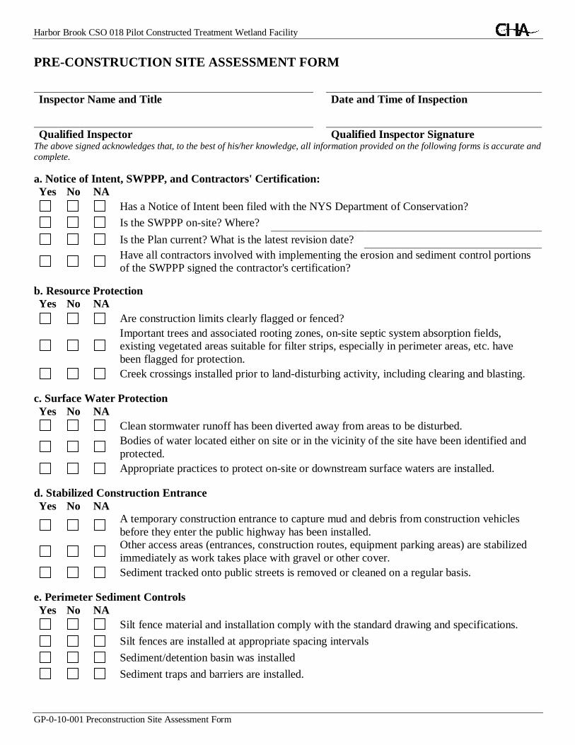
Harbor Brook CSO 018 Pilot Constructed Treatment Wetland Facility
GP-0-10-001 Preconstruction Site Assessment Form
PRE-CONSTRUCTION SITE ASSESSMENT FORM
Inspector Name and Title Date and Time of Inspection
Qualified Inspector Qualified Inspector SignatureThe above signed acknowledges that, to the best of his/her knowledge, all information provided on the following forms is accurate andcomplete.
a. Notice of Intent, SWPPP, and Contractors' Certification:Yes No NA
Has a Notice of Intent been filed with the NYS Department of Conservation?
Is the SWPPP on-site? Where?
Is the Plan current? What is the latest revision date?Have all contractors involved with implementing the erosion and sediment control portionsof the SWPPP signed the contractor's certification?
b. Resource ProtectionYes No NA
Are construction limits clearly flagged or fenced?Important trees and associated rooting zones, on-site septic system absorption fields,existing vegetated areas suitable for filter strips, especially in perimeter areas, etc. havebeen flagged for protection.
Creek crossings installed prior to land-disturbing activity, including clearing and blasting.
c. Surface Water ProtectionYes No NA
Clean stormwater runoff has been diverted away from areas to be disturbed.Bodies of water located either on site or in the vicinity of the site have been identified andprotected.
Appropriate practices to protect on-site or downstream surface waters are installed.
d. Stabilized Construction EntranceYes No NA
A temporary construction entrance to capture mud and debris from construction vehiclesbefore they enter the public highway has been installed.Other access areas (entrances, construction routes, equipment parking areas) are stabilizedimmediately as work takes place with gravel or other cover.
Sediment tracked onto public streets is removed or cleaned on a regular basis.
e. Perimeter Sediment ControlsYes No NA
Silt fence material and installation comply with the standard drawing and specifications.
Silt fences are installed at appropriate spacing intervals
Sediment/detention basin was installed
Sediment traps and barriers are installed.


Appendix C


Appendix D


Page 1 of 10
New York State Department of Environmental Conservation
Division of Water
625 Broadway, 4th Floor
Albany, New York 12233-3505
NOTICE OF INTENT
All sections must be completed unless otherwise noted. Failure to complete all items mayresult in this form being returned to you, thereby delaying your coverage under thisGeneral Permit. Applicants must read and understand the conditions of the permit andprepare a Stormwater Pollution Prevention Plan prior to submitting this NOI. Applicantsare responsible for identifying and obtaining other DEC permits that may be required.
-IMPORTANT-RETURN THIS FORM TO THE ADDRESS ABOVE
OWNER/OPERATOR MUST SIGN FORM
Stormwater Discharges Associated with Construction Activity Under StatePollutant Discharge Elimination System (SPDES) General Permit # GP-0-10-001
Owner/Operator Information
Owner/Operator Contact Person Last Name (NOT CONSULTANT)
Owner/Operator Contact Person First Name
Owner/Operator Mailing Address
City
State Zip
-
Phone (Owner/Operator)
- -Fax (Owner/Operator)
- -
Email (Owner/Operator)
Owner/Operator (Company Name/Private Owner Name/Municipality Name)
NYR(for DEC use only)
FED TAX ID
- (not required for individuals)
0669273036

1. Provide the Geographic Coordinates for the project site in NYTM Units. To do this youmust go to the NYSDEC Stormwater Interactive Map on the DEC website at:
www.dec.ny.gov/imsmaps/stormwater/viewer.htm
Zoom into your Project Location such that you can accurately click on the centroid ofyour site. Once you have located your project site, go to the tool boxes on the top andchoose "i"(identify). Then click on the center of your site and a new window containingthe X, Y coordinates in UTM will pop up. Transcribe these coordinates into the boxesbelow. For problems with the interactive map use the help function.
X Coordinates (Easting) Y Coordinates (Northing)
Project Site Information
Project/Site Name
Street Address (NOT P.O. BOX)
City/Town/Village (THAT ISSUES BUILDING PERMIT)
State Zip
-County
Name of Nearest Cross Street
Distance to Nearest Cross Street (Feet) Project In Relation to Cross Street
North South East West
Page 2 of 10
2. What is the nature of this construction project?
New Construction
Redevelopment with increase in imperviousness
Redevelopment with no increase in imperviousness
Section-Block-ParcelTax Map Numbers
Side of Street
North South East West
DEC Region
Tax Map Numbers
0457273031

3. Select the predominant land use for both pre and post development conditions.SELECT ONLY ONE CHOICE FOR EACH
8. Do you plan to disturb more than 5 acres of soil at any one time?
9. Indicate the percentage of each Hydrologic Soil Group(HSG) at the site.
Page 3 of 10
Existing Land Use
FOREST
PASTURE/OPEN LAND
CULTIVATED LAND
SINGLE FAMILY HOME
SINGLE FAMILY SUBDIVISION
TOWN HOME RESIDENTIAL
MULTIFAMILY RESIDENTIAL
INSTITUTIONAL/SCHOOL
INDUSTRIAL
COMMERCIAL
ROAD/HIGHWAY
RECREATIONAL/SPORTS FIELD
BIKE PATH/TRAIL
LINEAR UTILITY
PARKING LOT
OTHER
. .
Future Land Use
SINGLE FAMILY HOME
SINGLE FAMILY SUBDIVISION
TOWN HOME RESIDENTIAL
MULTIFAMILY RESIDENTIAL
INSTITUTIONAL/SCHOOL
INDUSTRIAL
COMMERCIAL
MUNICIPAL
ROAD/HIGHWAY
RECREATIONAL/SPORTS FIELD
BIKE PATH/TRAIL
LINEAR UTILITY (water, sewer, gas, etc.)
PARKING LOT
CLEARING/GRADING ONLY
DEMOLITION, NO REDEVELOPMENT
OTHER
Yes No
Pre-Development Post-Development
4. Will future use of this site be an agricultural property as definedby the NYS Agriculture and Markets Law ? Yes No
Yes No5. Is this a project which does not require coverage under the GeneralPermit (e.g. Project done under an Individual SPDES Permit, ordepartment approved remediation)?
Yes No6. Is this property owned by a state authority, state agency or localgovernment?
A B C D
% % % %
Number of Lots
Total SiteAcreage
. .
Acreage ToBe Disturbed
Existing ImperviousArea Within Disturbed
Future ImperviousArea Within Disturbed
7. In accordance with the larger common plan of development or sale, enter the totalproject site acreage, the acreage to be disturbed and the future impervious area(acreage)within the disturbed area. Round to the nearest tenth of an acre.
6953273038
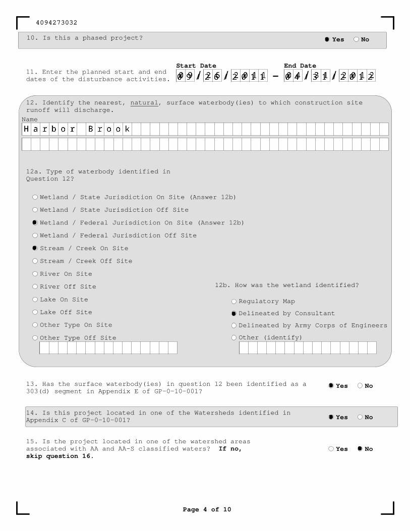
Page 4 of 10
Name
10. Is this a phased project? Yes No
11. Enter the planned start and enddates of the disturbance activities. -
Start Date
/ /End Date
/ /
12. Identify the nearest, natural, surface waterbody(ies) to which construction siterunoff will discharge.
12a. Type of waterbody identified inQuestion 12?
Wetland / State Jurisdiction On Site (Answer 12b)
Wetland / State Jurisdiction Off Site
Wetland / Federal Jurisdiction On Site (Answer 12b)
Wetland / Federal Jurisdiction Off Site
Stream / Creek On Site
Stream / Creek Off Site
River On Site
River Off Site
Lake On Site
Lake Off Site
Other Type On Site
Other Type Off Site
12b. How was the wetland identified?
Regulatory Map
Delineated by Consultant
Delineated by Army Corps of Engineers
Other (identify)
13. Has the surface waterbody(ies) in question 12 been identified as a303(d) segment in Appendix E of GP-0-10-001?
14. Is this project located in one of the Watersheds identified inAppendix C of GP-0-10-001?
Yes No
Yes No
15. Is the project located in one of the watershed areasassociated with AA and AA-S classified waters? If no,skip question 16.
Yes No
4094273032

18. Does the site runoff enter a separate storm sewer system(including roadside drains, swales, ditches, culverts, etc)?(If No, skip question 19)
19. What is the name of the municipality/entity that owns the separate storm sewer system?
Yes No Unknown
20. Does any runoff from the site enter a sewer classified asa Combined Sewer? Yes No Unknown
16. Does this construction activity disturb land with noexisting impervious cover and where the Soil Slope Phaseis identified as an E or F on the USDA Soil Survey?If Yes, what is the acreage to be disturbed?
Yes No
.
21. Has the required Erosion and Sediment Control component of theSWPPP been developed in conformance with the current NYS Standardsand Specifications for Erosion and Sediment Control (aka Blue Book) ?
22. Does this construction activity require the development of aSWPPP that includes Water Quality and Quantity Control components(Post-Construction Stormwater Management Practices)(If No, skip questions 23 and 27-35)
23. Have the Water Quality and Quantity Control components of the SWPPPbeen developed in comformance with the current NYS Stormwater ManagementDesign Manual ?
Yes No
Yes No
Yes No
Page 5 of 10
17. Will the project disturb soils within a State regulatedwetland or the protected 100 foot adjacent area? Yes No
3151273035

Page 6 of 10
SWPPP Preparer
Contact Name (Last, Space, First)
Mailing Address
City
State Zip
-Phone
- -Fax
Signature
Date
/ /
First Name
Last Name
MI
SWPPP Preparer Certification
24. The Stormwater Pollution Prevention Plan (SWPPP) was prepared by:
Professional Engineer (P.E.)
Soil and Water Conservation District (SWCD)
Registered Landscape Architect (R.L.A)
Certified Professional in Erosion and Sediment Control (CPESC)
Owner/Operator
Other
I hereby certify that the Stormwater Pollution Prevention Plan (SWPPP) forthis project has been prepared in accordance with the terms and conditions ofthe GP-0-10-001. Furthermore, I understand that certifying false, incorrector inaccurate information is a violation of this permit and the laws of theState of New York and could subject me to criminal, civil and/oradministrative proceedings.
3663273033

26. Select all of the erosion and sediment control practices that will be employedon the project site:
Page 7 of 10
Biotechnical
Brush Matting
Wattling
Other
25. Has a construction sequence schedule for the planned managementpractices been prepared? Yes No
Brush Matting
Dune Stabilization
Grassed Waterway
Mulching
Protecting Vegetation
Recreation Area Improvement
Seeding
Sodding
Straw/Hay Bale Dike
Streambank Protection
Temporary Swale
Topsoiling
Vegetating Waterways
Vegetative Measures
Check Dams
Construction Road Stabilization
Dust Control
Earth Dike
Level Spreader
Perimeter Dike/Swale
Pipe Slope Drain
Portable Sediment Tank
Rock Dam
Sediment Basin
Sediment Traps
Silt Fence
Stabilized Construction Entrance
Storm Drain Inlet Protection
Straw/Hay Bale Dike
Temporary Access Waterway Crossing
Temporary Stormdrain Diversion
Temporary Swale
Turbidity Curtain
Water bars
Temporary Structural
Debris Basin
Diversion
Grade Stabilization Structure
Land Grading
Lined Waterway (Rock)
Paved Channel (Concrete)
Paved Flume
Retaining Wall
Riprap Slope Protection
Rock Outlet Protection
Streambank Protection
Permanent Structural
7654273037
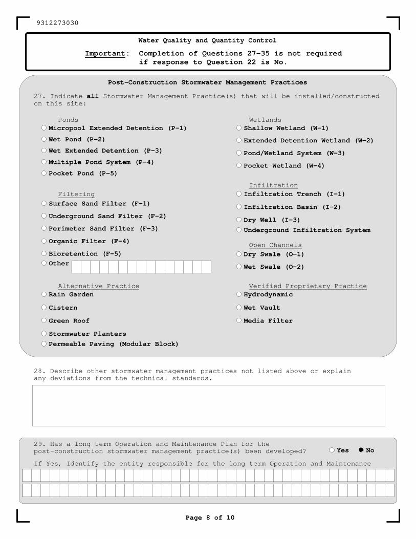
Page 8 of 10
27. Indicate all Stormwater Management Practice(s) that will be installed/constructedon this site:
Micropool Extended Detention (P-1)
Wet Pond (P-2)
Wet Extended Detention (P-3)
Multiple Pond System (P-4)
Pocket Pond (P-5)
Ponds
Filtering
Surface Sand Filter (F-1)
Underground Sand Filter (F-2)
Perimeter Sand Filter (F-3)
Organic Filter (F-4)
Bioretention (F-5)
Other
Dry Swale (O-1)
Wet Swale (O-2)
Infiltration Trench (I-1)
Infiltration Basin (I-2)
Dry Well (I-3)
Underground Infiltration System
Infiltration
Shallow Wetland (W-1)
Extended Detention Wetland (W-2)
Pond/Wetland System (W-3)
Pocket Wetland (W-4)
28. Describe other stormwater management practices not listed above or explainany deviations from the technical standards.
29. Has a long term Operation and Maintenance Plan for thepost-construction stormwater management practice(s) been developed?
If Yes, Identify the entity responsible for the long term Operation and Maintenance
Yes No
Open Channels
Wetlands
Rain Garden
Cistern
Green Roof
Stormwater Planters
Permeable Paving (Modular Block)
Alternative Practice Verified Proprietary PracticeHydrodynamic
Wet Vault
Media Filter
Post-Construction Stormwater Management Practices
Water Quality and Quantity Control
Important: Completion of Questions 27-35 is not requiredif response to Question 22 is No.
9312273030
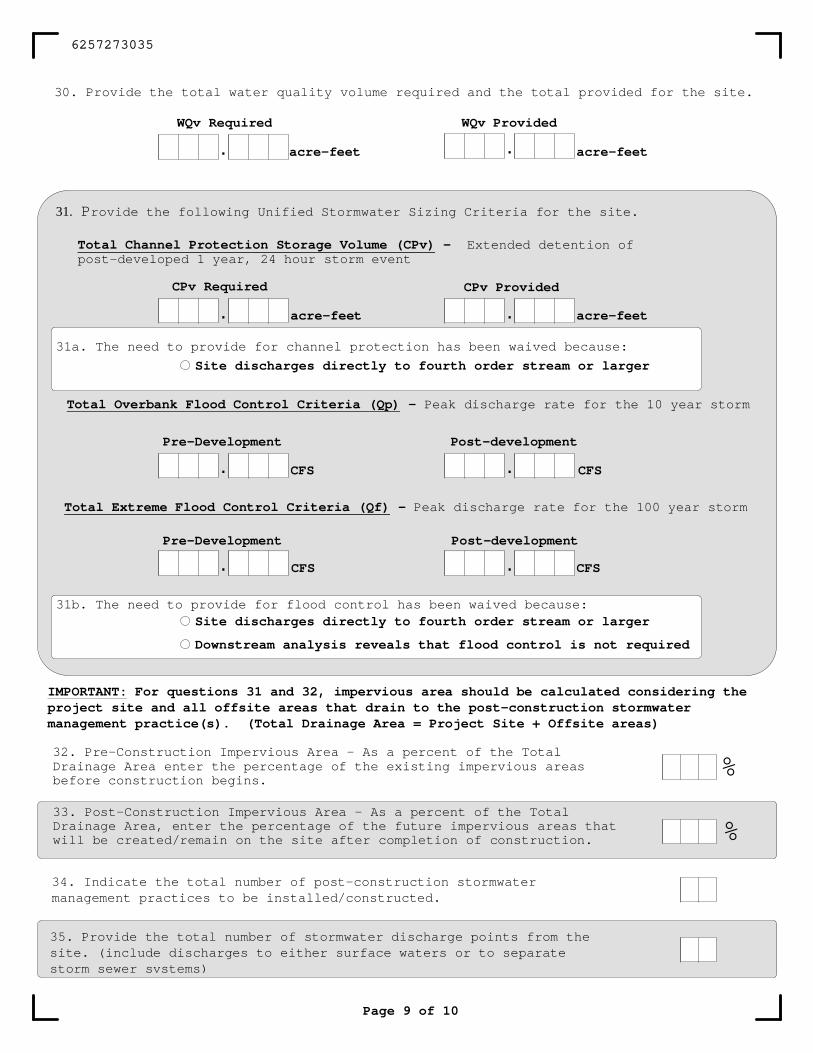
Page 9 of 10
IMPORTANT: For questions 31 and 32, impervious area should be calculated considering theproject site and all offsite areas that drain to the post-construction stormwatermanagement practice(s). (Total Drainage Area = Project Site + Offsite areas)
32. Pre-Construction Impervious Area - As a percent of the TotalDrainage Area enter the percentage of the existing impervious areasbefore construction begins.
33. Post-Construction Impervious Area - As a percent of the TotalDrainage Area, enter the percentage of the future impervious areas thatwill be created/remain on the site after completion of construction.
WQv Required WQv Provided
. acre-feet
30. Provide the total water quality volume required and the total provided for the site.
. acre-feet
31b. The need to provide for flood control has been waived because:
. CFS CFS.Post-developmentPre-Development
Total Extreme Flood Control Criteria (Qf) - Peak discharge rate for the 100 year storm
. CFS . CFS
Post-developmentPre-Development
Total Overbank Flood Control Criteria (Qp) - Peak discharge rate for the 10 year storm
Site discharges directly to fourth order stream or larger
31a. The need to provide for channel protection has been waived because:
. acre-feet
CPv Provided
acre-feet.
CPv Required
Total Channel Protection Storage Volume (CPv) - Extended detention ofpost-developed 1 year, 24 hour storm event
31. Provide the following Unified Stormwater Sizing Criteria for the site.
Site discharges directly to fourth order stream or larger
Downstream analysis reveals that flood control is not required
34. Indicate the total number of post-construction stormwatermanagement practices to be installed/constructed.
35. Provide the total number of stormwater discharge points from thesite. (include discharges to either surface waters or to separatestorm sewer systems)
%
%
6257273035
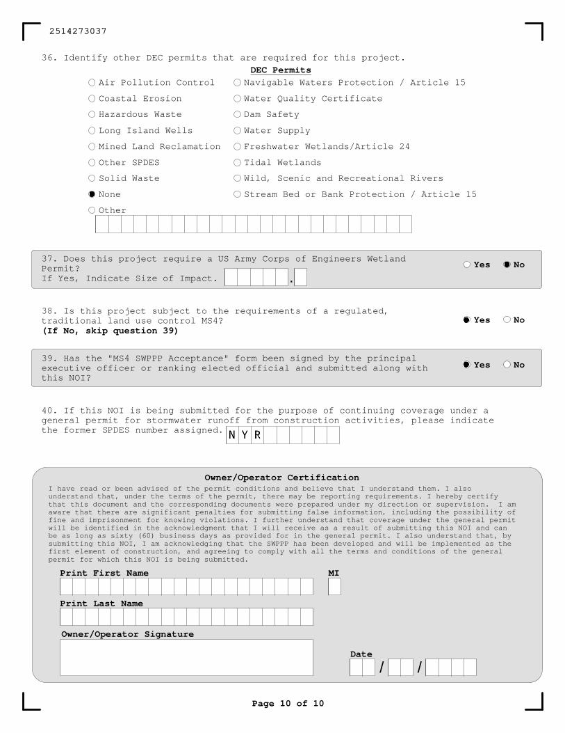
Page 10 of 10
DEC Permits
36. Identify other DEC permits that are required for this project.
40. If this NOI is being submitted for the purpose of continuing coverage under ageneral permit for stormwater runoff from construction activities, please indicatethe former SPDES number assigned.
Owner/Operator CertificationI have read or been advised of the permit conditions and believe that I understand them. I alsounderstand that, under the terms of the permit, there may be reporting requirements. I hereby certifythat this document and the corresponding documents were prepared under my direction or supervision. I amaware that there are significant penalties for submitting false information, including the possibility offine and imprisonment for knowing violations. I further understand that coverage under the general permitwill be identified in the acknowledgment that I will receive as a result of submitting this NOI and canbe as long as sixty (60) business days as provided for in the general permit. I also understand that, bysubmitting this NOI, I am acknowledging that the SWPPP has been developed and will be implemented as thefirst element of construction, and agreeing to comply with all the terms and conditions of the generalpermit for which this NOI is being submitted.
Owner/Operator Signature
Date
/ /
Print First Name
Print Last Name
MI
38. Is this project subject to the requirements of a regulated,traditional land use control MS4?(If No, skip question 39)
Yes No
39. Has the "MS4 SWPPP Acceptance" form been signed by the principalexecutive officer or ranking elected official and submitted along withthis NOI?
Yes No
Air Pollution Control
Coastal Erosion
Hazardous Waste
Long Island Wells
Mined Land Reclamation
Other SPDES
Solid Waste
None
Other
Navigable Waters Protection / Article 15
Water Quality Certificate
Dam Safety
Water Supply
Freshwater Wetlands/Article 24
Tidal Wetlands
Wild, Scenic and Recreational Rivers
Stream Bed or Bank Protection / Article 15
37. Does this project require a US Army Corps of Engineers WetlandPermit?If Yes, Indicate Size of Impact.
Yes No
.
2514273037

NEW YORK STATEDEPARTMENT OF ENVIRONMENTAL CONSERVATION
SPDES GENERAL PERMITFOR STORMWATER DISCHARGES
from
CONSTRUCTION ACTIVITY
Permit No. GP-O-IO-00 I
Issued Pursuant to Article 17, Titles 7.8 and Article 70of the Environmental Conservation Law
Effective Date: January 29, 2010
William R. AdrianceChief Pennit Administrator
Expiration Date: January 28, 2015
Address: NYS DECDiv. Environmental Permits625 Broadway, 4th FloorAlbany, N.Y. 12233-1750
I

2
PREFACE
Pursuant to Section 402 of the Clean Water Act (“CWA”), stormwater discharges from certain construction activities are unlawful unless they are authorized by a National Pollutant Discharge Elimination System (“NPDES”) permit or by a state permit program. New York’s State Pollutant Discharge Elimination System (“SPDES”) is a NPDES-approved program with permits issued in accordance with the Environmental Conservation Law (“ECL”).
This general permit (“permit”) is issued pursuant to Article 17, Titles 7, 8 and Article 70 of the ECL. An owner or operator may obtain coverage under this permit by submitting a Notice of Intent ("NOI") to the Department. Copies of this permit and the NOI for New York are available by calling (518) 402-8109 or at any New York State Department of Environmental Conservation (“the Department”) regional office (see Appendix G).They are also available on the Department’s website at:
http://www.dec.ny.gov/
An owner or operator of a construction activity that is eligible for coverage under this permit must obtain coverage prior to the commencement of construction activity. Activities that fit the definition of “construction activity”, as defined under 40 CFR 122.26(b)(14)(x), (15)(i), and (15)(ii), constitute construction of a point source and therefore, pursuant to Article 17-0505 of the ECL, the owner or operator must have coverage under a SPDES permit prior to commencing construction activity. They cannot wait until there is an actual discharge from the construction site to obtain permit coverage. *Note: The italicized words/phrases within this permit are defined in Appendix A.
3
NEW YORK STATE DEPARTMENT OF ENVIRONMENTAL CONSERVATION SPDES GENERAL PERMIT FOR STORMWATER DISCHARGES
FROM CONSTRUCTION ACTIVITIES
TABLE OF CONTENTS
Part I. PERMIT COVERAGE AND LIMITATIONS ....................................................................... 5
A. Permit Application .................................................................................................................... 5 B. Maintaining Water Quality ........................................................................................................ 5 C. Eligibility Under This General Permit ...................................................................................... 5 D. Activities Which Are Ineligible for Coverage Under This General Permit .............................. 6
Part II. OBTAINING PERMIT COVERAGE .................................................................................. 7 A. Notice of Intent (NOI) Submittal .............................................................................................. 7 B. Permit Authorization ................................................................................................................. 8 C. General Requirements For Owners or Operators With Permit Coverage ................................. 9 D. Permit Coverage for Discharges Authorized Under GP-0-08-001 ......................................... 11 E. Change of Owner or Operator ................................................................................................. 11
Part III. STORMWATER POLLUTION PREVENTION PLAN (SWPPP) ................................... 11 A. General SWPPP Requirements ............................................................................................... 11 B. Required SWPPP Contents ..................................................................................................... 14 C. Required SWPPP Components by Project Type ..................................................................... 18
Part IV. INSPECTION AND MAINTENANCE REQUIREMENTS ............................................. 18 A. General Construction Site Inspection and Maintenance Requirements .................................. 18 B. Owner or Operator Maintenance Inspection Requirements .................................................... 18 C. Qualified Inspector Inspection Requirements ......................................................................... 19
Part V. TERMINATION OF PERMIT COVERAGE ..................................................................... 22 A. Termination of Permit Coverage ............................................................................................. 22
Part VI. REPORTING AND RETENTION OF RECORDS ........................................................... 24 A. Record Retention ..................................................................................................................... 24 B. Addresses ................................................................................................................................ 24
Part VII. STANDARD PERMIT CONDITIONS ........................................................................... 24 A. Duty to Comply ....................................................................................................................... 24 B. Continuation of the Expired General Permit ........................................................................... 25 C. Enforcement ............................................................................................................................ 25 D. Need to Halt or Reduce Activity Not a Defense ..................................................................... 25 E. Duty to Mitigate ...................................................................................................................... 25 F. Duty to Provide Information .................................................................................................... 25 G. Other Information ................................................................................................................... 25 H. Signatory Requirements .......................................................................................................... 26 I. Property Rights ......................................................................................................................... 27 J. Severability ............................................................................................................................... 27 K. Denial of Coverage Under This Permit ................................................................................... 28 L. Proper Operation and Maintenance ......................................................................................... 28 M. Inspection and Entry ............................................................................................................... 28 N. Permit Actions......................................................................................................................... 29 O. Definitions ............................................................................................................................... 29

P. Re-Opener Clause .................................................................................................................... 29 Q. Penalties for Falsification of Forms and Reports .................................................................... 29 R. Other Permits........................................................................................................................... 29
APPENDIX A .................................................................................................................................. 30 APPENDIX B .................................................................................................................................. 35 APPENDIX C .................................................................................................................................. 37 APPENDIX D .................................................................................................................................. 42 APPENDIX E .................................................................................................................................. 43 APPENDIX F................................................................................................................................... 45
4

5
Part I. PERMIT COVERAGE AND LIMITATIONS
A. Permit Application - This permit authorizes stormwater discharges to surface waters of the State from the following construction activities identified within 40 CFR Parts 122.26(b)(14)(x), 122.26(b)(15)(i) and 122.26(b)(15)(ii), provided all of the eligibility provisions of this permit are met:
1. Construction activities involving soil disturbances of one (1) or more acres;
including disturbances of less than one acre that are part of a larger common plan of development or sale that will ultimately disturb one or more acres of land; excluding routine maintenance activity that is performed to maintain the original line and grade, hydraulic capacity or original purpose of a facility;
2. Construction activities involving soil disturbances of less than one (1) acre
where the Department has determined that a SPDES permit is required for stormwater discharges based on the potential for contribution to a violation of a water quality standard or for significant contribution of pollutants to surface waters of the State.
3. Construction activities located in the watershed(s) identified in Appendix D that
involve soil disturbances between five thousand (5000) square feet and one (1) acre of land.
B. Maintaining Water Quality - It shall be a violation of this permit and the ECL for any
discharge to either cause or contribute to a violation of water quality standards as contained in Parts 700 through 705 of Title 6 of the Official Compilation of Codes, Rules and Regulations of the State of New York, such as:
1. There shall be no increase in turbidity that will cause a substantial visible
contrast to natural conditions;
2. There shall be no increase in suspended, colloidal or settleable solids that will cause deposition or impair the waters for their best usages; and
3. There shall be no residue from oil and floating substances, nor visible oil film,
nor globules of grease.
C. Eligibility Under This General Permit 1. This permit may authorize all discharges of stormwater from construction
activity to surface waters of the State and groundwaters except for ineligible discharges identified under subparagraph D. of this Part.
2. Except for non-stormwater discharges explicitly listed in the next paragraph,
this permit only authorizes stormwater discharges from construction activities.

6
(Part I. C) 3. Notwithstanding paragraphs C.1 and C.2 above, the following non-stormwater
discharges may be authorized by this permit: discharges from fire fighting activities; fire hydrant flushings; waters to which cleansers or other components have not been added that are used to wash vehicles or control dust in accordance with the SWPPP, routine external building washdown which does not use detergents; pavement washwaters where spills or leaks of toxic or hazardous materials have not occurred (unless all spilled material has been removed) and where detergents are not used; air conditioning condensate; uncontaminated groundwater or spring water; uncontaminated discharges from construction site de-watering operations; and foundation or footing drains where flows are not contaminated with process materials such as solvents. For those entities required to obtain coverage under this permit, and who discharge as noted in this paragraph, and with the exception of flows from fire fighting activities, these discharges must be identified in the SWPPP. Under all circumstances, the owner or operator must still comply with water quality standards in Part I.B.
D. Activities Which Are Ineligible for Coverage Under This General Permit - All of the following are not authorized by this permit:
1. Discharges after construction activities have been completed and the site has
undergone final stabilization;
2. Discharges that are mixed with sources of non-stormwater other than those expressly authorized under subsection C.3. of this Part and identified in the SWPPP required by this permit;
3. Discharges that are required to obtain an individual SPDES permit or another
SPDES general permit pursuant to Part VII, subparagraph K of this permit;
4. Discharges from construction activities that adversely affect a listed, or proposed to be listed, endangered or threatened species, or its critical habitat;
5. Discharges which either cause or contribute to a violation of water quality standards adopted pursuant to the ECL and its accompanying regulations;
6. Construction activities for residential, commercial and institutional projects
that:
a. are tributary to waters of the state classified as AA or AA-s; and
7
(Part I. D. 6) b. disturb one or more acres of land with no existing impervious cover and
where the Soil Slope Phase is identified as an E or F on the USDA Soil Survey for the County in which the disturbance will occur.
7. Construction activities for linear transportation projects and linear utility projects that:
a. are tributary to waters of the state classified as AA or AA-s; and
b. disturb two or more acres of land with no existing impervious cover and where the Soil Slope Phase is identified as an E or F on the USDA Soil Survey for the County in which the disturbance will occur.
8. Construction activities that adversely affect a property that is listed or is eligible
for listing on the State or National Register of Historic Places (Note: includes Archeological sites), unless there are written agreements in place with the NYS Office of Parks, Recreation and Historic Preservation (OPRHP) or other governmental agencies to mitigate the effects, or there are local land use approvals evidencing the same.
Part II. OBTAINING PERMIT COVERAGE
A. Notice of Intent (NOI) Submittal 1. An owner or operator of a construction activity that is not subject to the
requirements of a regulated, traditional land use control MS4 must first develop a SWPPP in accordance with all applicable requirements of this permit and then submit a completed NOI form to the address below in order to be authorized to discharge under this permit. The NOI form shall be one which is associated with this permit, signed in accordance with Part VII.H. of this permit.
NOTICE OF INTENT NYS DEC, Bureau of Water Permits 625 Broadway, 4th Floor Albany, New York 12233-3505
2. An owner or operator of a construction activity that is subject to the
requirements of a regulated, traditional land use control MS4 must first develop a SWPPP in accordance with all applicable requirements of this permit and then have its SWPPP reviewed and accepted by the MS4 prior to submitting the NOI to the Department. The owner or operator shall have the “MS4 SWPPP Acceptance” form signed by the principal executive officer or ranking elected official from the regulated, traditional land use control MS4, or by a duly authorized representative of that person, and then submit that form along with the NOI to the address referenced under “Notice of Intent (NOI) Submittal”.

8
(Part II. A.2)
This requirement does not apply to an owner or operator that is obtaining permit coverage in accordance with the requirements in Part II.E. (Change of Owner or Operator).
3. The owner or operator shall have the SWPPP preparer sign the “SWPPP Preparer Certification” statement on the NOI prior to submitting the form to the Department.
4. As of the date the NOI is submitted to the Department, the owner or operator
shall make the NOI and SWPPP available for review and copying in accordance with the requirements in Part VII.F. of this permit.
B. Permit Authorization
1. An owner or operator shall not commence construction activity until their
authorization to discharge under this permit goes into effect. 2. Authorization to discharge under this permit will be effective when the owner
or operator has satisfied all of the following criteria: a. project review pursuant to the State Environmental Quality Review Act
(SEQRA) have been satisfied, when SEQRA is applicable,
b. where required, all necessary Department permits subject to the Uniform Procedures Act (UPA) (see 6 NYCRR Part 621) have been obtained, unless otherwise notified by the Department pursuant to 6 NYCRR 621.3(a)(4). Owners or operators of construction activities that are required to obtain UPA permits must submit a preliminary SWPPP to the appropriate DEC Regional Office in Appendix F at the time all other necessary UPA permit applications are submitted. The preliminary SWPPP must include sufficient information to demonstrate that the construction activity qualifies for authorization under this permit,
c. the final SWPPP has been prepared, and
d. an NOI has been submitted to the Department in accordance with the
requirements of this permit.
3. An owner or operator that has satisfied the requirements of Part II.B.2 above will be authorized to discharge stormwater from their construction activity in accordance with the following schedule:

9
(Part II. B. 3) a. For construction activities that are not subject to the requirements of a
regulated, traditional land use control MS4:
i. Five (5) business days from the date the Department receives a complete NOI for construction activities with a SWPPP that has been prepared in conformance with the technical standards referenced in Parts III.B.1, 2 and/or 3, or
ii. Sixty (60) business days from the date the Department
receives a complete NOI for construction activities with a SWPPP that has not been prepared in conformance with the technical standards referenced in Parts III.B.1, 2 or 3.
b. For construction activities that are subject to the requirements of a
regulated, traditional land use control MS4:
i. Five (5) business days from the date the Department receives a complete NOI and signed “MS4 SWPPP Acceptance” form,
4. The Department may suspend or deny an owner’s or operator’s coverage under
this permit if the Department determines that the SWPPP does not meet the permit requirements.
5. Coverage under this permit authorizes stormwater discharges from only those
areas of disturbance that are identified in the NOI. If an owner or operator wishes to have stormwater discharges from future or additional areas of disturbance authorized, they must submit a new NOI that addresses that phase of the development, unless otherwise notified by the Department.
C. General Requirements For Owners or Operators With Permit Coverage
1. The owner or operator shall ensure that the provisions of the SWPPP are
implemented from the commencement of construction activity until all areas of disturbance have achieved final stabilization and the Notice of Termination (NOT) has been submitted to the Department in accordance with Part V. of this permit. This includes any changes made to the SWPPP pursuant to Part III.A.4.
2. The owner or operator shall maintain a copy of the General Permit (GP-0-10-
001), NOI, NOI Acknowledgment Letter, SWPPP, MS4 SWPPP Acceptance form and inspection reports at the construction site until all disturbed areas have achieved final stabilization and the NOT has been submitted to the Department.

10
(Part II. C. 2) The documents must be maintained in a secure location, such as a job trailer, on-site construction office, or mailbox with lock. The secure location must be accessible during normal business hours to an individual performing a compliance inspection.
3. The owner or operator of a construction activity shall not disturb greater than
five (5) acres of soil at any one time without prior written authorization from the Department or, in areas under the jurisdiction of a regulated, traditional land use control MS4, the MS4 (provided the MS4 is not the owner or operator of the construction activity). At a minimum, the owner or operator must comply with the following requirements in order to be authorized to disturb greater than five (5) acres of soil at any one time:
a. The owner or operator shall have a qualified inspector conduct at least
two (2) site inspections in accordance with Part IV.C. every seven (7) calendar days, for as long as greater than five (5) acres of soil remain disturbed. The two (2) inspections shall be separated by a minimum of two (2) full calendar days.
b. In areas where soil disturbance activity has been temporarily or
permanently ceased, temporary and/or permanent soil stabilization measures shall be installed and/or implemented within seven (7) days from the date the soil disturbance activity ceased. The soil stabilization measures selected shall be in conformance with the most current version of the technical standard, New York State Standards and Specifications for Erosion and Sediment Control.
c. The owner or operator shall prepare a phasing plan that defines
maximum disturbed area per phase and shows required cuts and fills.
d. The owner or operator shall install any additional site specific practices needed to protect water quality.
e. The owner or operator shall include the requirements above in their
SWPPP.
4. The Department may suspend or revoke an owner’s or operator’s coverage under this permit at any time if the Department determines that the SWPPP does not meet the permit requirements.

11
(Part II. C) 5. For construction activities that are subject to the requirements of a regulated,
traditional land use control MS4, the owner or operator shall notify the MS4 in writing of any planned amendments or modifications to the post-construction stormwater management practice component of the SWPPP required by Part III.A. 4. and 5. of this permit. Unless otherwise notified by the MS4, the owner or operator shall have the SWPPP amendments or modifications reviewed and accepted by the MS4 prior to commencing construction of the post-construction stormwater management practice.
D. Permit Coverage for Discharges Authorized Under GP-0-08-001
1. Upon renewal of SPDES General Permit for Stormwater Discharges from
Construction Activity (Permit No. GP-0-08-001), an owner or operator of construction activity with coverage under GP-0-08-001, as of the effective date of GP-0-10-001, shall be authorized to discharge in accordance with GP-0-10-001 unless otherwise notified by the Department.
E. Change of Owner or Operator
1. When property ownership changes or when there is a change in operational
control over the construction plans and specifications, the original owner or operator must notify the new owner or operator, in writing, of the requirement to obtain permit coverage by submitting a NOI with the Department. Once the new owner or operator obtains permit coverage, the original owner or operator shall then submit a completed NOT with the name and permit identification number of the new owner or operator to the Department at the address in Part II.A.1.. If the original owner or operator maintains ownership of a portion of the construction activity and will disturb soil, they must maintain their coverage under the permit. Permit coverage for the new owner or operator will be effective as of the date the Department receives a complete NOI, provided the original owner or operator was not subject to a sixty (60) business day authorization period that has not expired as of the date the Department receives the NOI from the new owner or operator.
Part III. STORMWATER POLLUTION PREVENTION PLAN (SWPPP)
A. General SWPPP Requirements
1. The SWPPP shall be prepared prior to the submittal of the NOI. The NOI shall be submitted to the Department prior to the commencement of construction activity.
12
(Part III. A) 2. The SWPPP shall describe the erosion and sediment control practices and where
required, post-construction stormwater management practices that will be used and/or constructed to reduce the pollutants in stormwater discharges and to assure compliance with the terms and conditions of this permit. In addition, the SWPPP shall identify potential sources of pollution which may reasonably be expected to affect the quality of stormwater discharges.
3. All SWPPPs that require the post-construction stormwater management practice
component shall be prepared by a qualified professional that is knowledgeable in the principles and practices of stormwater management and treatment.
4. The owner or operator must keep the SWPPP current so that it at all times accurately documents the erosion and sediment controls practices that are being used or will be used during construction, and all post-construction stormwater management practices that will be constructed on the site. At a minimum, the owner or operator shall amend the SWPPP:
a. whenever the current provisions prove to be ineffective in minimizing
pollutants in stormwater discharges from the site;
b. whenever there is a change in design, construction, or operation at the construction site that has or could have an effect on the discharge of pollutants; and
c. to address issues or deficiencies identified during an inspection by the
qualified inspector, the Department or other regulatory authority. 5. The Department may notify the owner or operator at any time that the SWPPP
does not meet one or more of the minimum requirements of this permit. The notification shall be in writing and identify the provisions of the SWPPP that require modification. Within fourteen (14) calendar days of such notification, or as otherwise indicated by the Department, the owner or operator shall make the required changes to the SWPPP and submit written notification to the Department that the changes have been made. If the owner or operator does not respond to the Department’s comments in the specified time frame, the Department may suspend the owner’s or operator’s coverage under this permit.
6. Prior to the commencement of construction activity, the owner or operator must
identify the contractor(s) and subcontractor(s) that will be responsible for installing, constructing, repairing, replacing, inspecting and maintaining the erosion and sediment control practices included in the SWPPP; and the contractor(s) and subcontractor(s) that will be responsible for constructing the post-construction stormwater management practices included in the SWPPP.

13
(Part III. A. 6) The owner or operator shall have each of the contractors and subcontractors identify at least one person from their company that will be responsible for implementation of the SWPPP. This person shall be known as the trained contractor. The owner or operator shall ensure that at least one trained contractor is on site on a daily basis when soil disturbance activities are being performed. The owner or operator shall have each of the contractors and subcontractors identified above sign a copy of the following certification statement below before they commence any construction activity:
"I hereby certify that I understand and agree to comply with the terms and conditions of the SWPPP and agree to implement any corrective actions identified by the qualified inspector during a site inspection. I also understand that the owner or operator must comply with the terms and conditions of the most current version of the New York State Pollutant Discharge Elimination System ("SPDES") general permit for stormwater discharges from construction activities and that it is unlawful for any person to cause or contribute to a violation of water quality standards. Furthermore, I understand that certifying false, incorrect or inaccurate information is a violation of the referenced permit and the laws of the State of New York and could subject me to criminal, civil and/or administrative proceedings. "
In addition to providing the certification statement above, the certification page must also identify the specific elements of the SWPPP that each contractor and subcontractor will be responsible for and include the name and title of the person providing the signature; the name and title of the trained contractor responsible for SWPPP implementation; the name, address and telephone number of the contracting firm; the address (or other identifying description) of the site; and the date the certification statement is signed. The owner or operator shall attach the certification statement(s) to the copy of the SWPPP that is maintained at the construction site. If new or additional contractors are hired to implement measures identified in the SWPPP after construction has commenced, they must also sign the certification statement and provide the information listed above.
7. For projects where the Department requests a copy of the SWPPP or inspection
reports, the owner or operator shall submit the documents in both electronic (PDF only) and paper format within five (5) business days, unless otherwise notified by the Department.
8. The SWPPP must include documentation supporting the determination of
permit eligibility with regard to Part I.D.8. (Historic Places or Archeological Resource). At a minimum, the supporting documentation shall include the following:

14
(Part III. A. 8)
a. Information on whether the stormwater discharge or construction activities would have an effect on a property (historic or archeological resource) that is listed or eligible for listing on the State or National Register of Historic Places;
b. Results of historic resources screening determinations conducted.
Information regarding the location of historic places listed, or eligible for listing, on the State or National Registers of Historic Places and areas of archeological sensitivity that may indicate the need for a survey can be obtained online by viewing the New York State Office of Parks, Recreation and Historic Places (OPRHP) online resources located on their web site at: http://nysparks.state.ny.us/shpo/online-tools/ (using The Geographic Information System for Archeology and National Register). OPRHP can also be contacted at: NYS OPRHP, State Historic Preservation Office, Peebles Island Resources Center, P.O. Box 189, Waterford, NY 12188-0189, phone: 518-237-8643;
c. A description of measures necessary to avoid or minimize adverse
impacts on places listed, or eligible for listing, on the State or National Register of Historic Places. If the owner or operator fails to describe and implement such measures, the stormwater discharge is ineligible for coverage under this permit; and
d. Where adverse effects may occur, any written agreements in place with
OPRHP or other governmental agency to mitigate those effects, or local land use approvals evidencing the same.
B. Required SWPPP Contents
1. Erosion and sediment control component - All SWPPPs prepared pursuant to
this permit shall include erosion and sediment control practices designed in conformance with the most current version of the technical standard, New York State Standards and Specifications for Erosion and Sediment Control. Where erosion and sediment control practices are not designed in conformance with this technical standard, the owner or operator must demonstrate equivalence to the technical standard. At a minimum, the erosion and sediment control component of the SWPPP shall include the following:
a. Background information about the scope of the project, including the
location, type and size of project;

15
( Part III. B. 1) b. A site map/construction drawing(s) for the project, including a general
location map. At a minimum, the site map shall show the total site area; all improvements; areas of disturbance; areas that will not be disturbed; existing vegetation; on-site and adjacent off-site surface water(s), wetlands and drainage patterns that could be affected by the construction activity; existing and final slopes; locations of different soil types with boundaries; material, waste, borrow or equipment storage areas located on adjacent properties; and location(s) of the stormwater discharge(s);
c. A description of the soil(s) present at the site, including an identification
of the Hydrologic Soil Group (HSG);
d. A construction phasing plan and sequence of operations describing the intended order of construction activities, including clearing and grubbing, excavation and grading, utility and infrastructure installation and any other activity at the site that results in soil disturbance;
e. A description of the minimum erosion and sediment control practices to
be installed or implemented for each construction activity that will result in soil disturbance. Include a schedule that identifies the timing of initial placement or implementation of each erosion and sediment control practice and the minimum time frames that each practice should remain in place or be implemented;
f. A temporary and permanent soil stabilization plan that meets the
requirements of the most current version of the technical standard, New York State Standards and Specifications for Erosion and Sediment Control, for each stage of the project, including initial land clearing and grubbing to project completion and achievement of final stabilization;
g. A site map/construction drawing(s) showing the specific location(s),
size(s), and length(s) of each erosion and sediment control practice;
h. The dimensions, material specifications, installation details, and operation and maintenance requirements for all erosion and sediment control practices. Include the location and sizing of any temporary sediment basins and structural practices that will be used to divert flows from exposed soils;

16
( Part III. B. 1) i. A maintenance inspection schedule for the contractor(s) identified in
Part III.A.6., to ensure continuous and effective operation of the erosion and sediment control practices. The maintenance inspection schedule shall be in accordance with the requirements in the most current version of the technical standard, New York State Standards and Specifications for Erosion and Sediment Control;
j. A description of the pollution prevention measures that will be used to
control litter, construction chemicals and construction debris from becoming a pollutant source in the stormwater discharges;
k. A description and location of any stormwater discharges associated with
industrial activity other than construction at the site, including, but not limited to, stormwater discharges from asphalt plants and concrete plants located on the construction site; and
l. Identification of any elements of the design that are not in conformance
with the requirements in the most current version of the technical standard, New York State Standards and Specifications for Erosion and Sediment Control. Include the reason for the deviation or alternative design and provide information which demonstrates that the deviation or alternative design is equivalent to the technical standards.
2. Post-construction stormwater management practice component - All
construction projects identified in Table 2 of Appendix B as needing post-construction stormwater management practices shall prepare a SWPPP that includes practices designed in conformance with the most current version of the technical standard, New York State Stormwater Management Design Manual (“Design Manual”). If the Design Manual is revised during the term of this permit, an owner or operator must begin using the revised version of the Design Manual to prepare their SWPPP six (6) months from the final revision date of the Design Manual. Where post-construction stormwater management practices are not designed in conformance with this technical standard, the owner or operator must demonstrate equivalence to the technical standard. At a minimum, the post-construction stormwater management practice component of the SWPPP shall include the following:
a. Identification of all post-construction stormwater management practices
to be constructed as part of the project;

17
(Part III. B. 2)
b. A site map/construction drawing(s) showing the specific location and size of each post-construction stormwater management practice;
c. The dimensions, material specifications and installation details for each
post-construction stormwater management practice;
d. Identification of any elements of the design that are not in conformance with the Design Manual. Include the reason for the deviation or alternative design and provide information which demonstrates that the deviation or alternative design is equivalent to the technical standards;
e. A hydrologic and hydraulic analysis for all structural components of the
stormwater management control system;
f. A detailed summary (including calculations) of the sizing criteria that was used to design all post-construction stormwater management practices. At a minimum, the summary shall address the required design criteria from the applicable chapter of the Design Manual; including the identification of and justification for any deviations from the Design Manual, and identification of any design criteria that are not required based on the design criteria or waiver criteria included in the Design Manual; and
g. An operations and maintenance plan that includes inspection and
maintenance schedules and actions to ensure continuous and effective operation of each post-construction stormwater management practice. The plan shall identify the entity that will be responsible for the long term operation and maintenance of each practice.
3. Enhanced Phosphorus Removal Standards - All construction projects identified
in Table 2 of Appendix B that are located in the watersheds identified in Appendix C shall prepare a SWPPP that includes post-construction stormwater management practices designed in conformance with the Enhanced Phosphorus Removal Standards included in the Design Manual. At a minimum, the post-construction stormwater management practice component of the SWPPP shall include items 2.a - 2.g. above.

18
(Part III. C) C. Required SWPPP Components by Project Type - Unless otherwise notified by the Department, owners or operators of construction activities identified in Table 1 of Appendix B are required to prepare a SWPPP that only includes erosion and sediment control practices designed in conformance with Part III.B.1. Owners or operators of the construction activities identified in Table 2 of Appendix B shall prepare a SWPPP that also includes post-construction stormwater management practices designed in conformance with Part III.B.2 or 3.
Part IV. INSPECTION AND MAINTENANCE REQUIREMENTS
A. General Construction Site Inspection and Maintenance Requirements
1. The owner or operator must ensure that all erosion and sediment control practices and all post-construction stormwater management practices identified in the SWPPP are maintained in effective operating condition at all times.
2. The terms of this permit shall not be construed to prohibit the State of New
York from exercising any authority pursuant to the ECL, common law or federal law, or prohibit New York State from taking any measures, whether civil or criminal, to prevent violations of the laws of the State of New York, or protect the public health and safety and/or the environment.
B. Owner or Operator Maintenance Inspection Requirements
1. The owner or operator shall inspect, in accordance with the requirements in the most current version of the technical standard, New York State Standards and Specifications for Erosion and Sediment Control, the erosion and sediment controls identified in the SWPPP to ensure that they are being maintained in effective operating condition at all times.
2. For construction sites where soil disturbance activities have been temporarily
suspended (e.g. winter shutdown) and temporary stabilization measures have been applied to all disturbed areas, the owner or operator can stop conducting the maintenance inspections. The owner or operator shall begin conducting the maintenance inspections in accordance with Part IV.B.1. as soon as soil disturbance activities resume.
3. For construction sites where soil disturbance activities have been shut down
with partial project completion, the owner or operator can stop conducting the maintenance inspections if all areas disturbed as of the project shutdown date have achieved final stabilization and all post-construction stormwater management practices required for the completed portion of the project have been constructed in conformance with the SWPPP and are operational.

19
(Part IV. C) C. Qualified Inspector Inspection Requirements - The owner or operator shall have a qualified inspector conduct site inspections in conformance with the following requirements: [Note: The trained contractor identified in Part III.A.6. cannot conduct the qualified inspector site inspections unless they meet the qualified inspector qualifications included in Appendix A. In order to perform these inspections, the trained contractor would have to be a:
• Licensed Professional Engineer, • Certified Professional in Erosion and Sediment Control (CPESC), • Registered Landscape Architect, or • Someone working under the direct supervision of, and at the same company as, the licensed Professional Engineer or Registered Landscape Architect, provided they have received four (4) hours of Department endorsed training in proper erosion and sediment control principles from a Soil and Water Conservation District, or other Department endorsed entity]. 1. A qualified inspector shall conduct site inspections for all construction activities
identified in Tables 1 and 2 of Appendix B, with the exception of:
a. the construction of a single family residential subdivision with 25% or less impervious cover at total site build-out that involves a soil disturbance of one (1) or more acres of land but less than five (5) acres and is not located in one of the watersheds listed in Appendix C and not directly discharging to one of the 303(d) segments listed in Appendix E;
b. the construction of a single family home that involves a soil disturbance
of one (1) or more acres of land but less than five (5) acres and is not located in one of the watersheds listed in Appendix C and not directly discharging to one of the 303(d) segments listed in Appendix E;
c. construction on agricultural property that involves a soil disturbance of
one (1) or more acres of land but less than five (5) acres; and
d. construction activities located in the watersheds identified in Appendix D that involve soil disturbances between five thousand (5000) square feet and one (1) acre of land.
2. Unless otherwise notified by the Department, the qualified inspector shall
conduct site inspections in accordance with the following timetable:
a. For construction sites where soil disturbance activities are on-going, the qualified inspector shall conduct a site inspection at least once every seven (7) calendar days.
20
(Part IV. C. 2) b. For construction sites where soil disturbance activities are on-going and
the owner or operator has received authorization in accordance with Part II.C.3 to disturb greater than five (5) acres of soil at any one time, the qualified inspector shall conduct at least two (2) site inspections every seven (7) calendar days. The two (2) inspections shall be separated by a minimum of two (2) full calendar days.
c. For construction sites where soil disturbance activities have been
temporarily suspended (e.g. winter shutdown) and temporary stabilization measures have been applied to all disturbed areas, the qualified inspector shall conduct a site inspection at least once every thirty (30) calendar days. The owner or operator shall notify the Regional Office stormwater contact person (see contact information in Appendix F) or, in areas under the jurisdiction of a regulated, traditional land use control MS4, the MS4 (provided the MS4 is not the owner or operator of the construction activity) in writing prior to reducing the frequency of inspections.
d. For construction sites where soil disturbance activities have been shut
down with partial project completion, the qualified inspector can stop conducting inspections if all areas disturbed as of the project shutdown date have achieved final stabilization and all post-construction stormwater management practices required for the completed portion of the project have been constructed in conformance with the SWPPP and are operational. The owner or operator shall notify the Regional Office stormwater contact person (see contact information in Appendix F) or, in areas under the jurisdiction of a regulated, traditional land use control MS4, the MS4 (provided the MS4 is not the owner or operator of the construction activity). in writing prior to the shutdown. If soil disturbance activities are not resumed within 2 years from the date of shutdown, the owner or operator shall have the qualified inspector perform a final inspection and certify that all disturbed areas have achieved final stabilization, and all temporary, structural erosion and sediment control measures have been removed; and that all post-construction stormwater management practices have been constructed in conformance with the SWPPP by signing the “Final Stabilization” and “Post-Construction Stormwater Management Practice” certification statements on the NOT. The owner or operator shall then submit the completed NOT form to the address in Part II.A.1..

21
(Part IV. C. 3) 3. At a minimum, the qualified inspector shall inspect all erosion and sediment
control practices to ensure integrity and effectiveness, all post-construction stormwater management practices under construction to ensure that they are constructed in conformance with the SWPPP, all areas of disturbance that have not achieved final stabilization, all points of discharge to natural surface waterbodies located within, or immediately adjacent to, the property boundaries of the construction site, and all points of discharge from the construction site.
4. The qualified inspector shall prepare an inspection report subsequent to each
and every inspection. At a minimum, the inspection report shall include and/or address the following:
a. Date and time of inspection;
b. Name and title of person(s) performing inspection;
c. A description of the weather and soil conditions (e.g. dry, wet, saturated)
at the time of the inspection;
d. A description of the condition of the runoff at all points of discharge from the construction site. This shall include identification of any discharges of sediment from the construction site. Include discharges from conveyance systems (i.e. pipes, culverts, ditches, etc.) and overland flow;
e. A description of the condition of all natural surface waterbodies located
within, or immediately adjacent to, the property boundaries of the construction site which receive runoff from disturbed areas. This shall include identification of any discharges of sediment to the surface waterbody;
f. Identification of all erosion and sediment control practices that need
repair or maintenance;
g. Identification of all erosion and sediment control practices that were not installed properly or are not functioning as designed and need to be reinstalled or replaced;
h. Description and sketch of areas that are disturbed at the time of the
inspection and areas that have been stabilized (temporary and/or final) since the last inspection;

22
(Part IV. C 4)
i. Current phase of construction of all post-construction stormwater management practices and identification of all construction that is not in conformance with the SWPPP and technical standards;
j. Corrective action(s) that must be taken to install, repair, replace or
maintain erosion and sediment control practices; and to correct deficiencies identified with the construction of the post-construction stormwater management practice(s); and
k. Digital photographs, with date stamp, that clearly show the condition of
all practices that have been identified as needing corrective actions. The qualified inspector shall attach paper color copies of the digital photographs to the inspection report being maintained onsite within seven (7) calendar days of the date of the inspection. The qualified inspector shall also take digital photographs, with date stamp, that clearly show the condition of the practice(s) after the corrective action has been completed. The qualified inspector shall attach paper color copies of the digital photographs to the inspection report that documents the completion of the corrective action work within seven (7) calendar days of that inspection.
5. Within one business day of the completion of an inspection, the qualified
inspector shall notify the owner or operator and appropriate contractor or subcontractor identified in Part III.A.6. of any corrective actions that need to be taken. The contractor or subcontractor shall begin implementing the corrective actions within one business day of this notification and shall complete the corrective actions in a reasonable time frame.
6. All inspection reports shall be signed by the qualified inspector. Pursuant to
Part II.C.2., the inspection reports shall be maintained on site with the SWPPP.
Part V. TERMINATION OF PERMIT COVERAGE A. Termination of Permit Coverage
1. An owner or operator that is eligible to terminate coverage under this permit
must submit a completed NOT form to the address in Part II.A.1. The NOT form shall be one which is associated with this general permit, signed in accordance with Part VII.H.
2. An owner or operator may terminate coverage when one or more the following
conditions have been met:

23
(Part V. A. 2) a. Total project completion - All construction activity identified in the
SWPPP has been completed; and all areas of disturbance have achieved final stabilization; and all temporary, structural erosion and sediment control measures have been removed; and all post-construction stormwater management practices have been constructed in conformance with the SWPPP and are operational;
b. Planned shutdown with partial project completion - All soil disturbance
activities have ceased; and all areas disturbed as of the project shutdown date have achieved final stabilization; and all temporary, structural erosion and sediment control measures have been removed; and all post-construction stormwater management practices required for the completed portion of the project have been constructed in conformance with the SWPPP and are operational;
c. A new owner or operator has obtained coverage under this permit in
accordance with Part II.E.
3. For construction activities meeting subdivision 2a. or 2b. of this Part, the owner or operator shall have the qualified inspector perform a final site inspection prior to submitting the NOT. The qualified inspector shall, by signing the “Final Stabilization” and “Post-Construction Stormwater Management Practice” certification statements on the NOT, certify that all disturbed areas have achieved final stabilization; and all temporary, structural erosion and sediment control measures have been removed; and that all post-construction stormwater management practices have been constructed in conformance with the SWPPP.
4. For construction activities that are subject to the requirements of a regulated,
traditional land use control MS4 and meet subdivision 2a. or 2b. of this Part, the owner or operator shall also have the MS4 sign the “MS4 Acceptance” statement on the NOT. The owner or operator shall have the principal executive officer, ranking elected official, or duly authorized representative from the regulated, traditional land use control MS4, sign the “MS4 Acceptance” statement. The MS4 official, by signing this statement, has determined that it is acceptable for the owner or operator to submit the NOT in accordance with the requirements of this Part. The MS4 can make this determination by performing a final site inspection themselves or by accepting the qualified inspector’s final site inspection certification(s) required in Part V.3.
5. For construction activities that require post-construction stormwater
management practices and meet subdivision 2a. of this Part, the owner or operator must, prior to submitting the NOT, ensure one of the following:

24
(Part V. A. 5) a. the post-construction stormwater management practice(s) and any right-
of-way(s) needed to maintain such practice(s) have been deeded to the municipality in which the practice(s) is located,
b. an executed maintenance agreement is in place with the municipality
that will maintain the post-construction stormwater management practice(s),
c. for post-construction stormwater management practices that are
privately owned, the owner or operator has modified their deed of record to include a deed covenant that requires operation and maintenance of the practice(s) in accordance with the operation and maintenance plan,
d. for post-construction stormwater management practices that are owned
by a public or private institution (e.g. school, college, university), or government agency or authority, the owner or operator has policy and procedures in place that ensures operation and maintenance of the practices in accordance with the operation and maintenance plan.
Part VI. REPORTING AND RETENTION OF RECORDS
A. Record Retention - The owner or operator shall retain a copy of the NOI, NOI Acknowledgment Letter, SWPPP, MS4 SWPPP Acceptance form and any inspection reports that were prepared in conjunction with this permit for a period of at least five (5) years from the date that the site achieves final stabilization. This period may be extended by the Department, in its sole discretion, at any time upon written notification.
B. Addresses - With the exception of the NOI, NOT, and MS4 SWPPP Acceptance form (which must be submitted to the address referenced in Part II.A.1), all written correspondence requested by the Department, including individual permit applications, shall be sent to the address of the appropriate Department Regional Office listed in Appendix F.
Part VII. STANDARD PERMIT CONDITIONS
A. Duty to Comply - The owner or operator must comply with all conditions of this permit. All contractors and subcontractors associated with the project must comply with the terms of the SWPPP. Any non-compliance with this permit constitutes a violation of the Clean Water Act (CWA) and the ECL and is grounds for an enforcement action against the owner or operator and/or the contractor/subcontractor; permit revocation, suspension or modification; or denial of a permit renewal application. Upon a finding of significant non-compliance with this permit or the applicable SWPPP, the Department may order an immediate stop to all construction activity at the site until the non-compliance is remedied.

25
(Part VII. A) The stop work order shall be in writing, shall describe the non-compliance in detail, and shall be sent to the owner or operator.
B. Continuation of the Expired General Permit - This permit expires five (5) years from the effective date. However, coverage may be obtained under the expired general permit, which will continue in force and effect, until a new general permit is issued. Unless otherwise notified by the Department in writing, an owner or operator seeking authorization under the new general permit must submit a new NOI in accordance with the terms of such new general permit.
C. Enforcement - Failure of the owner or operator, its contractors, subcontractors, agents and/or assigns to strictly adhere to any of the permit requirements contained herein shall constitute a violation of this permit. There are substantial criminal, civil, and administrative penalties associated with violating the provisions of this permit. Fines of up to $37,500 per day for each violation and imprisonment for up to fifteen (15) years may be assessed depending upon the nature and degree of the offense. D. Need to Halt or Reduce Activity Not a Defense - It shall not be a defense for an owner or operator in an enforcement action that it would have been necessary to halt or reduce the construction activity in order to maintain compliance with the conditions of this permit. E. Duty to Mitigate - The owner or operator and its contractors and subcontractors shall take all reasonable steps to minimize or prevent any discharge in violation of this permit which has a reasonable likelihood of adversely affecting human health or the environment. F. Duty to Provide Information - The owner or operator shall make available to the Department for review and copying or furnish to the Department within five (5) business days of receipt of a Department request for such information, any information requested for the purpose of determining compliance with this permit. This can include, but is not limited to, the NOI, NOI Acknowledgment Letter, SWPPP, MS4 SWPPP Acceptance form, executed maintenance agreement, and inspection reports. Failure to provide information requested by the Department within the request timeframe shall be a violation of this permit. The NOI, SWPPP and inspection reports required by this permit are public documents that the owner or operator must make available for review and copying by any person within five (5) business days of the owner or operator receiving a written request by any such person to review the NOI, SWPPP or inspection reports. Copying of documents will be done at the requester’s expense. G. Other Information - When the owner or operator becomes aware that they failed to submit any relevant facts, or submitted incorrect information in the NOI or in any other report, or have made substantive revisions to the SWPPP (e.g. the scope of the project changes significantly, the type of post-construction stormwater management practice(s)
26
(Part VII. G) changes, there is a reduction in the sizing of the post-construction stormwater management practice, or there is an increase in the disturbance area or impervious area), which were not reflected in the original NOI submitted to the Department, they shall promptly submit such facts or information to the Department. Failure of the owner or operator to correct or supplement any relevant facts within five (5) business days of becoming aware of the deficiency shall constitute a violation of this permit. H. Signatory Requirements
1. All NOIs and NOTs shall be signed as follows:
a. For a corporation these forms shall be signed by a responsible corporate officer. For the purpose of this section, a responsible corporate officer means:
i. a president, secretary, treasurer, or vice-president of the
corporation in charge of a principal business function, or any other person who performs similar policy or decision-making functions for the corporation; or
ii. the manager of one or more manufacturing, production or operating facilities, provided the manager is authorized to make management decisions which govern the operation of the regulated facility including having the explicit or implicit duty of making major capital investment recommendations, and initiating and directing other comprehensive measures to assure long term environmental compliance with environmental laws and regulations; the manager can ensure that the necessary systems are established or actions taken to gather complete and accurate information for permit application requirements; and where authority to sign documents has been assigned or delegated to the manager in accordance with corporate procedures;
b. For a partnership or sole proprietorship these forms shall be signed by a
general partner or the proprietor, respectively; or
c. For a municipality, State, Federal, or other public agency these forms shall be signed by either a principal executive officer or ranking elected official. For purposes of this section, a principal executive officer of a Federal agency includes:
i. the chief executive officer of the agency, or

27
(Part VII. H. 1. c) ii. a senior executive officer having responsibility for the overall
operations of a principal geographic unit of the agency (e.g., Regional Administrators of EPA).
2. The SWPPP and other information requested by the Department shall be signed
by a person described in Part VII.H.1. or by a duly authorized representative of that person. A person is a duly authorized representative only if:
a. The authorization is made in writing by a person described in Part
VII.H.1.;
b. The authorization specifies either an individual or a position having responsibility for the overall operation of the regulated facility or activity, such as the position of plant manager, operator of a well or a well field, superintendent, position of equivalent responsibility, or an individual or position having overall responsibility for environmental matters for the company. (A duly authorized representative may thus be either a named individual or any individual occupying a named position) and,
c. The written authorization shall include the name, title and signature of
the authorized representative and be attached to the SWPPP.
3. All inspection reports shall be signed by the qualified inspector that performs the inspection.
4. The MS4 SWPPP Acceptance form shall be signed by the principal executive
officer or ranking elected official from the regulated, traditional land use control MS4, or by a duly authorized representative of that person. It shall constitute a permit violation if an incorrect and/or improper signatory authorizes any required forms, SWPPP and/or inspection reports.
I. Property Rights - The issuance of this permit does not convey any property rights of any sort, nor any exclusive privileges, nor does it authorize any injury to private property nor any invasion of personal rights, nor any infringement of Federal, State or local laws or regulations. Owners or operators must obtain any applicable conveyances, easements, licenses and/or access to real property prior to commencing construction activity. J. Severability - The provisions of this permit are severable, and if any provision of this permit, or the application of any provision of this permit to any circumstance, is held invalid, the application of such provision to other circumstances, and the remainder of this permit shall not be affected thereby.
28
(Part VII. K) K. Denial of Coverage Under This Permit
1. At its sole discretion, the Department may require any owner or operator authorized by this permit to apply for and/or obtain either an individual SPDES permit or another SPDES general permit. When the Department requires any discharger authorized by a general permit to apply for an individual SPDES permit, it shall notify the discharger in writing that a permit application is required. This notice shall include a brief statement of the reasons for this decision, an application form, a statement setting a time frame for the owner or operator to file the application for an individual SPDES permit, and a deadline, not sooner than 180 days from owner or operator receipt of the notification letter, whereby the authorization to discharge under this general permit shall be terminated. Applications must be submitted to the appropriate Regional Office. The Department may grant additional time upon demonstration, to the satisfaction of the Regional Water Engineer, that additional time to apply for an alternative authorization is necessary or where the Department has not provided a permit determination in accordance with Part 621 of this Title.
2. Any owner or operator authorized by this permit may request to be excluded
from the coverage under this permit by applying for an individual permit or another general permit. In such cases, the owner or operator shall submit an individual application or an alternative general permit application in accordance with the requirements of this general permit, 40 CFR 122.26(c)(1)(ii) and 6 NYCRR Part 621, with reasons supporting the request, to the Department at the address for the appropriate Department Office (see addresses in Appendix F).The request may be granted by issuance of an individual permit or another general permit at the discretion of the Department.
3. When an individual SPDES permit is issued to a discharger authorized to
discharge under a general SPDES permit for the same discharge(s), the general permit authorization for outfalls authorized under the individual SPDES permit is automatically terminated on the effective date of the individual permit unless termination is earlier in accordance with 6 NYCRR Part 750.
L. Proper Operation and Maintenance - The owner or operator shall at all times properly operate and maintain all facilities and systems of treatment and control (and related appurtenances) which are installed or used by the owner or operator to achieve compliance with the conditions of this permit and with the requirements of the SWPPP. M. Inspection and Entry - The owner or operator shall allow the Department or an authorized representative of EPA, the State, or, in the case of a construction site which discharges through an MS4, an authorized representative of the MS4 receiving the discharge, upon the presentation of credentials and other documents as may be required by law, to:

29
(Part VII. M) 1. Enter upon the owner’s or operator's premises where a regulated facility or
activity is located or conducted or where records must be kept under the conditions of this permit;
2. Have access to and copy at reasonable times, any records that must be kept
under the conditions of this permit; and
3. Inspect at reasonable times any facilities or equipment (including monitoring and control equipment).
N. Permit Actions - At the Department’s sole discretion, this permit may, at any time, be modified, suspended, revoked, or renewed. The filing of a request by the owner or operator for a permit modification, revocation and reissuance, termination, a notification of planned changes or anticipated noncompliance does not limit, diminish and/or stay compliance with any terms of this permit. O. Definitions - Definitions of key terms are included in Appendix A of this permit. P. Re-Opener Clause
1. If there is evidence indicating potential or realized impacts on water quality due to any stormwater discharge associated with construction activity covered by this permit, the owner or operator of such discharge may be required to obtain an individual permit or alternative general permit in accordance with Part VII.K. of this permit or the permit may be modified to include different limitations and/or requirements.
2. Permit modification, suspension or revocation will be conducted in accordance
with 6 NYCRR Part 621, 6 NYCRR 750-1.18, and 6 NYCRR 750-1.20.
Q. Penalties for Falsification of Forms and Reports – Article 17 of the ECL provides for a civil penalty of $37,500 per day per violation of this permit. Articles 175 and 210 of the New York State Penal Law provide for a criminal penalty of a fine and/or imprisonment for falsifying forms and reports required by this permit. R. Other Permits – Nothing in this permit relieves the owner or operator from a requirement to obtain any other permits required by law.

30
APPENDIX A
Definitions Alter Hydrology from Pre to Post-Development Conditions - means the post-development peak flow rate(s) has increased by more than 5% of the pre-developed condition for the design storm of interest (e.g. 10 yr and 100 yr). Combined Sewer - means a sewer that is designed to collect and convey both “sewage” and “stormwater”. Commence (Commencement of) Construction Activities - means the initial disturbance of soils associated with clearing, grading or excavation activities; or other construction related activities that disturb or expose soils such as demolition, stockpiling of fill material, and the initial installation of erosion and sediment control practices required in the SWPPP. See definition for “Construction Activity(ies)” also. Construction Activity(ies) - means any clearing, grading, excavation, filling, demolition or stockpiling activities that result in soil disturbance. Clearing activities can include, but are not limited to, logging equipment operation, the cutting and skidding of trees, stump removal and/or brush root removal. Construction activity does not include routine maintenance that is performed to maintain the original line and grade, hydraulic capacity, or original purpose of a facility. Direct Discharge (to a specific surface waterbody) - means that runoff flows from a construction site by overland flow and the first point of discharge is the specific surface waterbody, or runoff flows from a construction site to a separate storm sewer system and the first point of discharge from the separate storm sewer system is the specific surface waterbody. Discharge(s) - means any addition of any pollutant to waters of the State through an outlet or point source. Environmental Conservation Law (ECL) - means chapter 43-B of the Consolidated Laws of the State of New York, entitled the Environmental Conservation Law. Final Stabilization - means that all soil disturbance activities have ceased and a uniform, perennial vegetative cover with a density of eighty (80) percent over the entire pervious surface has been established; or other equivalent stabilization measures, such as permanent landscape mulches, rock rip-rap or washed/crushed stone have been applied on all disturbed areas that are not covered by permanent structures, concrete or pavement. General SPDES permit - means a SPDES permit issued pursuant to 6 NYCRR Part 750-1.21 authorizing a category of discharges. Groundwater - means waters in the saturated zone. The saturated zone is a subsurface zone in

31
which all the interstices are filled with water under pressure greater than that of the atmosphere. Although the zone may contain gas-filled interstices or interstices filled with fluids other than water, it is still considered saturated. Impervious Area (Cover) - means all impermeable surfaces that cannot effectively infiltrate rainfall. This includes paved, concrete and gravel surfaces (i.e. parking lots, driveways, roads, runways and sidewalks); building rooftops and miscellaneous impermeable structures such as patios, pools, and sheds. Larger Common Plan of Development or Sale - means a contiguous area where multiple separate and distinct construction activities are occurring, or will occur, under one plan. The term “plan” in “larger common plan of development or sale” is broadly defined as any announcement or piece of documentation (including a sign, public notice or hearing, marketing plan, advertisement, drawing, permit application, State Environmental Quality Review Act (SEQRA) application, zoning request, computer design, etc.) or physical demarcation (including boundary signs, lot stakes, surveyor markings, etc.) indicating that construction activities may occur on a specific plot. For discrete construction projects that are located within a larger common plan of development or sale that are at least 1/4 mile apart, each project can be treated as a separate plan of development or sale provided any interconnecting road, pipeline or utility project that is part of the same “common plan” is not concurrently being disturbed. Municipal Separate Storm Sewer (MS4) - a conveyance or system of conveyances (including roads with drainage systems, municipal streets, catch basins, curbs, gutters, ditches, man-made channels, or storm drains):
i. Owned or operated by a State, city, town, borough, county, parish, district, association, or other public body (created by or pursuant to State law) having jurisdiction over disposal of sewage, industrial wastes, stormwater, or other wastes, including special districts under State law such as a sewer district, flood control district or drainage district, or similar entity, or an Indian tribe or an authorized Indian tribal organization, or a designated and approved management agency under section 208 of the CWA that discharges to surface waters of the State;
ii. Designed or used for collecting or conveying stormwater; iii. Which is not a combined sewer; and iv. Which is not part of a Publicly Owned Treatment Works (POTW) as defined at 40 CFR
122.2. National Pollutant Discharge Elimination System (NPDES) - means the national system for the issuance of wastewater and stormwater permits under the Federal Water Pollution Control Act (Clean Water Act). NOI Acknowledgment Letter - means the letter that the Department sends to an owner or operator to acknowledge the Department’s receipt and acceptance of a complete Notice of Intent. This letter documents the owner’s or operator’s authorization to discharge in accordance with the general permit for stormwater discharges from construction activity.
32
Owner or Operator - means the person, persons or legal entity which owns or leases the property on which the construction activity is occurring; and/or an entity that has operational control over the construction plans and specifications, including the ability to make modifications to the plans and specifications. Pollutant - means dredged spoil, filter backwash, solid waste, incinerator residue, sewage, garbage, sewage sludge, munitions, chemical wastes, biological materials, radioactive materials, heat, wrecked or discarded equipment, rock, sand and industrial, municipal, agricultural waste and ballast discharged into water; which may cause or might reasonably be expected to cause pollution of the waters of the state in contravention of the standards or guidance values adopted as provided in Parts 700 et seq of this Title. Qualified Inspector - means a person that is knowledgeable in the principles and practices of erosion and sediment control, such as a licensed Professional Engineer, Certified Professional in Erosion and Sediment Control (CPESC), Registered Landscape Architect, or other Department endorsed individual(s). It can also mean someone working under the direct supervision of, and at the same company as, the licensed Professional Engineer or Registered Landscape Architect, provided that person has training in the principles and practices of erosion and sediment control. Training in the principles and practices of erosion and sediment control means that the individual working under the direct supervision of the licensed Professional Engineer or Registered Landscape Architect has received four (4) hours of Department endorsed training in proper erosion and sediment control principles from a Soil and Water Conservation District, or other Department endorsed entity. After receiving the initial training, the individual working under the direct supervision of the licensed Professional Engineer or Registered Landscape Architect shall receive four (4) hours of training every three (3) years. It can also mean a person that meets the Qualified Professional qualifications in addition to the Qualified Inspector qualifications. Note: Inspections of any post-construction stormwater management practices that include structural components, such as a dam for an impoundment, shall be performed by a licensed Professional Engineer. Qualified Professional - means a person that is knowledgeable in the principles and practices of stormwater management and treatment, such as a licensed Professional Engineer, Registered Landscape Architect or other Department endorsed individual(s). Individuals preparing SWPPPs that require the post-construction stormwater management practice component must have an understanding of the principles of hydrology, water quality management practice design, water quantity control design, and, in many cases, the principles of hydraulics in order to prepare a SWPPP that conforms to the Department’s technical standard. All components of the SWPPP that involve the practice of engineering, as defined by the NYS Education Law (see Article 145), shall be prepared by, or under the direct supervision of, a professional engineer licensed to practice in the State of New York.

33
Regulated, Traditional Land Use Control MS4 - means a city, town or village with land use control authority that is required to gain coverage under New York State DEC’s SPDES General Permit For Stormwater Discharges from Municipal Separate Stormwater Sewer Systems (MS4s). Routine Maintenance Activity - means construction activity that is performed to maintain the original line and grade, hydraulic capacity, or original purpose of a facility, including, but not limited to:
• Re-grading of gravel roads or parking lots, • Stream bank restoration projects (does not include the placement of spoil material), • Cleaning and shaping of existing roadside ditches and culverts that maintains the approximate original line and grade, and hydraulic capacity of the ditch, • Cleaning and shaping of existing roadside ditches that does not maintain the approximate original grade, hydraulic capacity and purpose of the ditch if the changes to the line and grade, hydraulic capacity or purpose of the ditch are installed to improve water quality and quantity controls (e.g. installing grass lined ditch), • Placement of aggregate shoulder backing that makes the transition between the road shoulder and the ditch or embankment, • Full depth milling and filling of existing asphalt pavements, replacement of concrete pavement slabs, and similar work that does not expose soil or disturb the bottom six (6) inches of subbase material, • Long-term use of equipment storage areas at or near highway maintenance facilities, • Removal of sediment from the edge of the highway to restore a previously existing sheet-flow drainage connection from the highway surface to the highway ditch or embankment, • Existing use of Canal Corp owned upland disposal sites for the canal, and • Replacement of curbs, gutters, sidewalks and guide rail posts.
State Pollutant Discharge Elimination System (SPDES) - means the system established pursuant to Article 17 of the ECL and 6 NYCRR Part 750 for issuance of permits authorizing discharges to the waters of the state. Surface Waters of the State - shall be construed to include lakes, bays, sounds, ponds, impounding reservoirs, springs, rivers, streams, creeks, estuaries, marshes, inlets, canals, the Atlantic ocean within the territorial seas of the state of New York and all other bodies of surface water, natural or artificial, inland or coastal, fresh or salt, public or private (except those private waters that do not combine or effect a junction with natural surface or underground waters), which are wholly or partially within or bordering the state or within its jurisdiction. Waters of the state are further defined in 6 NYCRR Parts 800 to 941. Temporary Stabilization - means that exposed soil has been covered with material(s) as set forth in the technical standard, New York Standards and Specifications for Erosion and Sediment Control, to prevent the exposed soil from eroding. The materials can include, but are not limited to, mulch, seed and mulch, and erosion control mats (e.g. jute twisted yarn, excelsior wood fiber mats).

34
Total Maximum Daily Loads (TMDLs) - A TMDL is the sum of the allowable loads of a single pollutant from all contributing point and nonpoint sources. It is a calculation of the maximum amount of a pollutant that a waterbody can receive on a daily basis and still meet water quality standards, and an allocation of that amount to the pollutant's sources. A TMDL stipulates wasteload allocations (WLAs) for point source discharges, load allocations (LAs) for nonpoint sources, and a margin of safety (MOS). Trained Contractor - means an employee from the contracting (construction) company, identified in Part III.A.6., that has received four (4) hours of Department endorsed training in proper erosion and sediment control principles from a Soil and Water Conservation District, or other Department endorsed entity. After receiving the initial training, the trained contractor shall receive four (4) hours of training every three (3) years. It can also mean an employee from the contracting (construction) company, identified in Part III.A.6., that meets the qualified inspector qualifications (e.g. licensed Professional Engineer, Certified Professional in Erosion and Sediment Control (CPESC), Registered Landscape Architect, or someone working under the direct supervision of, and at the same company as, the licensed Professional Engineer or Registered Landscape Architect, provided they have received four (4) hours of Department endorsed training in proper erosion and sediment control principles from a Soil and Water Conservation District, or other Department endorsed entity). The trained contractor will be responsible for the day to day implementation of the SWPPP. Uniform Procedures Act (UPA) Permit - means a permit required under 6 NYCRR Part 621 of the Environmental Conservation Law (ECL), Article 70. Water Quality Standard - means such measures of purity or quality for any waters in relation to their reasonable and necessary use as promulgated in 6 NYCRR Part 700 et seq.

35
APPENDIX B
Required SWPPP Components by Project Type
Table 1 CONSTRUCTION ACTIVITIES THAT REQUIRE THE PREPARATION OF A SWPPP
THAT ONLY INCLUDES EROSION AND SEDIMENT CONTROLS
The following construction activities that involve soil disturbances of one (1) or more acres of land, but less than five (5) acres:
• Single family home not located in one of the watersheds listed in Appendix C and not directly
discharging to one of the 303(d) segments listed in Appendix E • Single family residential subdivisions with 25% or less impervious cover at total site build-out
and not located in one of the watersheds listed in Appendix C and not directly discharging to one of the 303(d) segments listed in Appendix E
• Construction of a barn or other agricultural building, silo, stock yard or pen.
The following construction activities that involve soil disturbances of one (1) or more acres of land:
• Installation of underground, linear utilities; such as gas lines, fiber-optic cable, cable TV, electric, telephone, sewer mains, and water mains
• Environmental enhancement projects, such as wetland mitigation projects, stormwater retrofits and stream restoration projects
• Bike paths and trails • Sidewalk construction projects that are not part of a road/ highway construction or
reconstruction project • Slope stabilization projects • Slope flattening that changes the grade of the site, but does not significantly change the runoff
characteristics • Spoil areas that will be covered with vegetation • Land clearing and grading for the purposes of creating vegetated open space (i.e. recreational
parks, lawns, meadows, fields), excluding projects that alter hydrology from pre to post development conditions
• Athletic fields (natural grass) that do not include the construction or reconstruction of impervious area and do not alter hydrology from pre to post development conditions
• Demolition project where vegetation will be established and no redevelopment is planned • Overhead electric transmission line project that does not include the construction of permanent
access roads or parking areas surfaced with impervious cover • Structural practices as identified in Table II in the “Agricultural Management Practices Catalog
for Nonpoint Source Pollution in New York State”, excluding projects that involve soil disturbances of less than five acres and construction activities that include the construction or reconstruction of impervious area
The following construction activities that involve soil disturbances between five thousand (5000) square feet and one (1) acre of land:
• All construction activities located in the watersheds identified in Appendix D that involve soil disturbances between five thousand (5000) square feet and one (1) acre of land.

36
Table 2 CONSTRUCTION ACTIVITIES THAT REQUIRE THE PREPARATION OF A SWPPP
THAT INCLUDES POST-CONSTRUCTION STORMWATER MANAGEMENT PRACTICES
The following construction activities that involve soil disturbances of one (1) or more acres of land:
• Single family home located in one of the watersheds listed in Appendix C or directly discharging to one of the 303(d) segments listed in Appendix E
• Single family residential subdivisions located in one of the watersheds listed in Appendix C or directly discharging to one of the 303(d) segments listed in Appendix E
• Single family residential subdivisions that involve soil disturbances of between one (1) and five (5) acres of land with greater than 25% impervious cover at total site build-out
• Single family residential subdivisions that involve soil disturbances of five (5) or more acres of land, and single family residential subdivisions that involve soil disturbances of less than five (5) acres that are part of a larger common plan of development or sale that will ultimately disturb five or more acres of land
• Multi-family residential developments; includes townhomes, condominiums, senior housing complexes, apartment complexes, and mobile home parks
• Airports • Amusement parks • Campgrounds • Cemeteries that include the construction or reconstruction of impervious area (>5% of disturbed
area) or alter the hydrology from pre to post development conditions • Commercial developments • Churches and other places of worship • Construction of a barn or other agricultural building(e.g. silo) and structural practices as
identified in Table II in the “Agricultural Management Practices Catalog for Nonpoint Source Pollution in New York State” that include the construction or reconstruction of impervious area, excluding projects that involve soil disturbances of less than five acres.
• Golf courses • Institutional, includes hospitals, prisons, schools and colleges • Industrial facilities, includes industrial parks • Landfills • Municipal facilities; includes highway garages, transfer stations, office buildings, POTW’s and
water treatment plants • Office complexes • Sports complexes • Racetracks, includes racetracks with earthen (dirt) surface • Road construction or reconstruction • Parking lot construction or reconstruction • Athletic fields (natural grass) that include the construction or reconstruction of impervious area
(>5% of disturbed area) or alter the hydrology from pre to post development conditions • Athletic fields with artificial turf • Permanent access roads, parking areas, substations, compressor stations and well drilling pads,
surfaced with impervious cover, and constructed as part of an over-head electric transmission line project , wind-power project, cell tower project, oil or gas well drilling project or other linear utility project
• All other construction activities that include the construction or reconstruction of impervious area and alter the hydrology from pre to post development conditions, and are not listed in Table 1

37
APPENDIX C
Watersheds Where Enhanced Phosphorus Removal Standards Are Required Watersheds where owners or operators of construction activities identified in Table 2 of Appendix B must prepare a SWPPP that includes post-construction stormwater management practices designed in conformance with the Enhanced Phosphorus Removal Standards included in the technical standard, New York State Stormwater Management Design Manual (“Design Manual”).
• Entire New York City Watershed located east of the Hudson River - Figure 1 • Onondaga Lake Watershed - Figure 2 • Greenwood Lake Watershed -Figure 3 • Oscawana Lake Watershed – Figure 4

Figure 1 - New York City Watershed East of the Hudson
38

Figure 2 - Onondaga Lake Watershed
39

40
Figure 3 - Greenwood Lake Watershed

41
igure 4 - Oscawana Lake WatershedF

APPENDIX D
42
Watersheds where owners or operators of construction activities that involve soil disturbances between five thousand (5000) square feet and one (1) acre of land must obtain coverage under this permit.
Entire New York City Watershed that is located east of the Hudson River - See Figure 1 in Appendix C
43
List of 303(d) segments impaired by pollutants related to construction activity (e.g. silt, sediment or nutrients). Owners or operators of single family home and single family residential subdivision construction activities that involve soil disturbances of one or more acres of land, but less than 5 acres, and directly discharge to one of the listed segments below shall prepare a SWPPP that includes post-construction stormwater management practices designed in conformance with the most current version of the technical standard, New York State Stormwater Management Design Manual (“Design Manual”).
COUNTY WATERBODY COUNTY WATERBODY
APPENDIX E
Albany Ann Lee (Shakers) Pond, Stump Pond Albany Basic Creek Reservoir Bronx Van Cortlandt Lake Broome Whitney Point Lake/Reservoir Broome Beaver Lake Broome White Birch Lake Chautauqua Chautauqua Lake, North Chautauqua Chautauqua Lake, South Chautauqua Bear Lake Chautauqua Chadakoin River and tribs Chautauqua Lower Cassadaga Lake Chautauqua Middle Cassadaga Lake Chautauqua Findley Lake Clinton Great Chazy River, Lower, Main Stem Columbia Kinderhook Lake Columbia Robinson Pond Dutchess Hillside Lake Dutchess Wappinger Lakes Dutchess Fall Kill and tribs Dutchess Rudd Pond Erie Rush Creek and tribs Erie Ellicott Creek, Lower, and tribs Erie Beeman Creek and tribs Erie Murder Creek, Lower, and tribs Erie South Branch Smoke Cr, Lower, and tribs Erie Little Sister Creek, Lower, and tribs Essex Lake George (primary county listed as Warren) Genesee Black Creek, Upper, and minor tribs Genesee Tonawanda Creek, Middle, Main Stem Genesee Tonawanda Creek, Upper, and minor tribs Genesee Little Tonawanda Creek, Lower, and tribs Genesee Oak Orchard Creek, Upper, and tribs Genesee Bowen Brook and tribs Genesee Bigelow Creek and tribs Greene Schoharie Reservoir Greene Sleepy Hollow Lake Herkimer Steele Creek tribs Kings Hendrix Creek Lewis Mill Creek/South Branch and tribs Livingston Conesus Lake Livingston Jaycox Creek and tribs Livingston Mill Creek and minor tribs
Monroe Genesee River, Lower, Main Stem Monroe Genesee River, Middle, Main Stem Monroe Black Creek, Lower, and minor tribs Monroe Buck Pond Monroe Long Pond Monroe Cranberry Pond Monroe Mill Creek and tribs Monroe Shipbuilders Creek and tribs Monroe Minor tribs to Irondequoit Bay Monroe Thomas Creek/White Brook and tribs Nassau Glen Cove Creek, Lower, and tribs Nassau LI Tribs (fresh) to East Bay Nassau East Meadow Brook, Upper, and tribs Nassau Hempstead Bay Nassau Hempstead Lake Nassau Grant Park Pond Niagara Bergholtz Creek and tribs Oneida Ballou, Nail Creeks Onondaga Ley Creek and tribs Onondaga Onondaga Creek, Lower and tribs Onondaga Onondaga creek, Middle and tribs Onondaga Onondaga Creek, Upper, and minor tribs Onondaga Harbor Brook, Lower, and tribs Onondaga Ninemile Creek, Lower, and tribs Onondaga Minor tribs to Onondaga Lake Ontario Honeoye Lake Ontario Hemlock Lake Outlet and minor tribs Ontario Great Brook and minor tribs Oswego Lake Neatahwanta Putnam Oscawana Lake Putnam Lake Carmel Queens Jamaica Bay, Eastern, and tribs (Queens) Queens Bergen Basin Queens Shellbank Basin Rensselaer Snyders Lake Richmond Grasmere, Arbutus and Wolfes Lakes Saratoga Dwaas Kill and tribs Saratoga Tribs to Lake Lonely Saratoga Lake Lonely Saratoga Schuyler Creek and tribs Schenectady Collins Lake
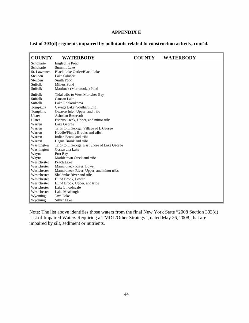
44
APPENDIX E
nt’d.
Y COUNTY WATERBODY
List of 303(d) segments impaired by pollutants related to construction activity, co
COUNTY WATERBODSchoharie Engleville Pond
ake Salubria teuben Smith Pond uffolk Millers Pond
Suffolk Mattituck (Marratooka) Pond
Suffolk Tidal tribs to West Moriches Bay Suffolk Canaan Lake Suffolk Lake Ronkonkoma Tompkins Cayuga Lake, Southern End Tompkins Owasco Inlet, Upper, and tribs Ulster Ashokan Reservoir Ulster Esopus Creek, Upper, and minor tribs Warren Lake George Warren Tribs to L.George, Village of L George Warren Huddle/Finkle Brooks and tribs Warren Indian Brook and tribs Warren Hague Brook and tribs Washington Tribs to L.George, East Shore of Lake George Washington Cossayuna Lake Wayne Port Bay Wayne Marbletown Creek and tribs Westchester Peach Lake Westchester Mamaroneck River, Lower Westchester Mamaroneck River, Upper, and minor tribs Westchester Sheldrake River and tribs Westchester Blind Brook, Lower Westchester Blind Brook, Upper, and tribs Westchester Lake Lincolndale Westchester Lake Meahaugh Wyoming Java Lake Wyoming Silver Lake
Schoharie Summit Lake St. Lawrence Black Lake Outlet/Black Lake Steuben L
SS
Note: The list above identifies those waters from the final New York State “2008 Section 303(d) List of Impaired Waters Requiring a TMDL/Other Strategy”, dated May 26, 2008, that are impaired by silt, sediment or nutrients.

45
APPENDIX F
LIST OF NYS DEC REGIONAL OFFICES
Region COVERING THE
FOLLOWING COUNTIES:
DIVISION OF
ENVIRONMENTAL PERMITS (DEP)
PERMIT ADMINISTRATORS
DIVISION OF WATER(DOW)
WATER (SPDES) PROGRAM
1 NASSAU AND SUFFOLK 50 CIRCLE ROAD STONY BROOK, NY
) 444-036511790-3409 11790
50 CIRCLE ROAD STONY BROOK, NY
TEL. (631 TEL. (631) 444-0405
2 NX, KINGS, NEW YORKBRO , QUE
1 HUNTERS POINT P40 21ST ST.
LONG ISLAND CITY 07 TEL. (718) 482-4997
ST ST. CITY, NY 11101-5407
82-4933
ENS AND RICHMOND 47-LAZA, 1 HUN
47-40 21, NY 11101-54
LONG I
SLAND
TEL. (718) 4
TERS POINT PLAZA,
3 UT
ROCKLAND, SULLIVA
D CHESS, ORANGE, PUTNAM, N LSTER
AND WESTCHESTER , U
21 SOUTH PUTT CO
NEW PALTZ, NY 12TEL. (845) 256-3059
E 1W RNERS ROAD 100 HILLSIDE AVENUE, SUIT
561-1696 WHITE PLAINS, NY 10603 TEL. (914) 428 - 2505
4 ALBANY, COLUMBIA, DELAW
RE
ARE,
S
CH OHARIE
1150 NORTH WEST
TADY, NY 1) 357-2069
DY, NY 12306-2014 7-2045
G ENE, MONTGOMERY, OT , R L ,
SCHENEC
TEL. (518EGO ENSSE AER
ENECTADY AND SCHS
COTT ROAD 1130 NORTH WESTCOTT ROAD 12306-20 4 SCHENECTA
TEL. (518) 35
5 NTON, ESSEX, FRANKCLI LIN, FUL RATOGA,
A TON
1115 STATE ROUTE RAY BROOK, NY 12TEL. (518) 897-1234
E ROAD,
TON, HAMILTON, SA
HINGW RREN AND WAS
86, PO B X 296 232 GOLF COURSO
977-0296 PO BOX 220 WARRENSBURG, NY 12885-0220
TEL. (518) 623-1200
6 HERKIMER, JEFFERSON, LEWIS, ONEIDA AND 31ST. LAWRENCE WATERTOW
315) 785-
STATE OFFICE B7 WASHINGTO
N, N224 793-2554
UILDING STATE OFFICE BUILDINGN STREET
207 GENESEE STREET
Y 13601-3787 UTICA, NY 13501-2885 TEL. ( 5 TEL. (315)
7 BRCH NANGO, CORTLAND, SYRAC
OE
A
M
1) 426-743
2400 -7500
OME, CAYUGA, 615 ERIE BLVD. W
M DISON, ONONDAGA, USE, NY
TEL. (315OSWEGO, TIOGA AND TO PKINS
EST 615 ERIE BLVD. WEST NY 13204-3204-2400 SYRACUSE,
4268 TEL. (315)
8 C MUNG, GENESEE, HEIVNT
SCHTE
YAT
ST AVONAVON, NY 14414-TEL. (585) 226-246
T AVON-LIMA RD. 14414-9519
2466 L INGSTON, MONROE, O ARIO, ORLEANS,
UYLER, SENECA, S UBEN, WAYNE AND
ES
6274 EA -LIMA ROAD 6274 EAS9519 AVON, NY
) 226-6 TEL. (585
9 EGANY, CATTARAUGUS, RIE,
270 MBUF
ALL
ICHIGAN AFALO, NY 14
TEL. (716) 851-716
HIGAN AVE. 3-2999
CHAUTAUQUA, ENIAGARA AND WYOMING
VENUE 270 MIC203-2999 BUFFALO, NY 1420
6) 851-70705 TEL. (71

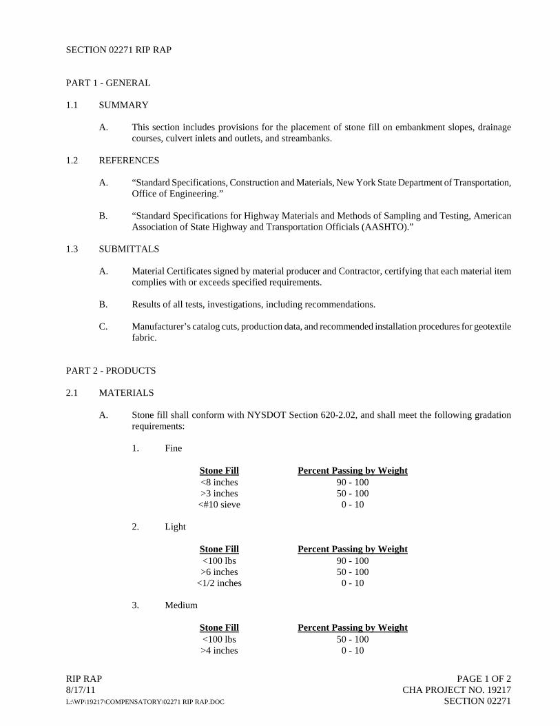
RIP RAP PAGE 1 OF 2 8/17/11 CHA PROJECT NO. 19217 L:\WP\19217\COMPENSATORY\02271 RIP RAP.DOC SECTION 02271
SECTION 02271 RIP RAP
PART 1 - GENERAL
1.1 SUMMARY
A. This section includes provisions for the placement of stone fill on embankment slopes, drainage courses, culvert inlets and outlets, and streambanks.
1.2 REFERENCES
A. “Standard Specifications, Construction and Materials, New York State Department of Transportation, Office of Engineering.”
B. “Standard Specifications for Highway Materials and Methods of Sampling and Testing, American Association of State Highway and Transportation Officials (AASHTO).”
1.3 SUBMITTALS
A. Material Certificates signed by material producer and Contractor, certifying that each material item complies with or exceeds specified requirements.
B. Results of all tests, investigations, including recommendations.
C. Manufacturer’s catalog cuts, production data, and recommended installation procedures for geotextile fabric.
PART 2 - PRODUCTS
2.1 MATERIALS
A. Stone fill shall conform with NYSDOT Section 620-2.02, and shall meet the following gradation requirements:
1. Fine
Stone Fill Percent Passing by Weight <8 inches >3 inches
<#10 sieve
90 - 100 50 - 100
0 - 10
2. Light
Stone Fill Percent Passing by Weight <100 lbs >6 inches
<1/2 inches
90 - 100 50 - 100
0 - 10
3. Medium
Stone Fill Percent Passing by Weight <100 lbs >4 inches
50 - 100 0 - 10

RIP RAP PAGE 2 OF 2 8/17/11 CHA PROJECT NO. 19217 L:\WP\19217\COMPENSATORY\02271 RIP RAP.DOC SECTION 02271
4. Heavy
Stone Fill Percent Passing by Weight <600 lbs
> 6 inches 50 - 100
0 - 10
B. Bedding shall conform with NYSDOT Section 620-2.05, and shall meet the following gradation requirements:
Stone Fill Percent Passing by Weight 4 inches 1 inch
1/4 inch No. 4
100 15 - 60 0 - 25 0 - 10
C. Geotextile: Shall conform to the requirements of Section “Geotextiles”.
PART 3 - EXECUTION
3.1 SURFACE PREPARATION
A. Clear the surface on which the rip-rap is to be placed of brush, trees, or other objectionable material.
3.2 INSTALLATION
A. Geotextile Fabric: Shall be installed in conformance with the requirements of Section “Geotextiles.”
B. Bedding
1. Place the bedding material on the geotextile to the full thickness, six (6) inch minimum, in one operation using methods that will not cause segregation of the aggregate.
2. Prevent contamination of bedding material by natural soils or other materials. Remove bedding materials that become contaminated and replace with uncontaminated bedding material.
3. Do not drop bedding material onto the geotextile from a height exceeding three (3) feet.
C. Stone Fill
1. Place the stones so that the dimension approximately equal to the layer thickness is perpendicular to the slope surface such that the weight of the stone is carried by the underlying material, not by the adjacent stones.
2. Place stone fill to minimize void spaces between adjacent stones.
3. On slopes the largest stones shall be placed at the bottom of the slope.
4. Place stone fill to avoid disruption and damage to the bedding material.
END OF SECTION

BURIED PIPE INSTALLATION PAGE 1 OF 12 8/17/11 CHA PROJECT NO. 19217 L:\WP\19217\COMPENSATORY\02610 BURIED PIPE INSTALLATION.DOC SECTION 02610
SECTION 02610 BURIED PIPE INSTALLATION
PART 1 - GENERAL
1.1 SUMMARY
A. This section includes the installation of buried piping.
1.2 REFERENCES
A. American Society of Testing and Materials (ASTM).
B. American National Standards Institute (ANSI).
C. American Water Works Association (AWWA).
D. Uni-Bell Plastic Pipe Association.
1.3 SUBMITTALS
A. Submit for approval a schedule for all proposed testing. Include proposed testing procedures indicating the sequence in which pipe sections will be tested and description of methods and equipment to be used.
B. Field Test Reports: Submit results of field testing directly to Engineer with copy to Contractor
1.4 STORAGE, AND HANDLING
A. Deliver and store materials within the Contract limits, as approved by Engineer.
B. Handle materials carefully with approved handling devices in accordance with manufacturer’s recommendations. Special care shall be exercised during delivery and storage to avoid damage to the materials.
C. Do not drop or roll products off trucks. Products are not to be otherwise dragged, rolled, or skidded.
D. Materials shall be stored on heavy wood blocking or platforms in accordance with the manufacturer’s instructions and recommendations. Materials shall not be in contact with the ground and their interiors shall be maintained free from dirt and other foreign matter.
E. Products cracked, gouged, chipped, dented, or otherwise damaged will not be approved and are to be removed and replaced at the Contractor’s expense, unless the product can be repaired in a manner acceptable to the manufacturer and the Engineer. All repairs shall be at the Contractor’s expense.
1.5 COORDINATION
A. Contractor shall be responsible for coordinating site utility work with other trades to ensure building service connection locations are verified and coordinated prior to commencing site instillation.

BURIED PIPE INSTALLATION PAGE 2 OF 12 8/17/11 CHA PROJECT NO. 19217 L:\WP\19217\COMPENSATORY\02610 BURIED PIPE INSTALLATION.DOC SECTION 02610
PART 2 - PRODUCTS
2.1 MATERIALS
A. Conform to individual pipe specification(s).
B. Pipe transition fittings: Shall be as indicated on the drawings. If not specifically indicated selection shall be based on pressure requirements of the system and types of materials being joined. Product selection shall be approved by the engineer.
C. Grout
1. Description: ASTM C 1107, Grade B, nonshrink and nonmetallic, dry hydraulic-cement grout.
a. Characteristics: Post hardening, volume adjusting, nonstaining, noncorrosive, nongaseous, and recommended for interior and exterior applications.
b. Design Mix: 5000-psi (34.5-MPa), 28-day compressive strength. c. Packaging: Premixed and factory packaged.
D. Flowable Fill
1. Description: Low-strength-concrete, flowable-slurry mix.
a. Cement: ASTM C 150, Type I, portland. b. Density: 115- to 145-lb/cu. ft.. c. Aggregates: ASTM C 33, natural sand, fine and crushed gravel or stone, coarse. d. Water: Comply with ASTM C 94/C 94M. e. Strength: 100 to 200 psig at 28 days.
PART 3 - EXECUTION
3.1 UTILITY DEMOLITION
A. Disconnect, demolish, and remove piped utility systems, equipment, and components indicated to be removed.
1. Piping to Be Removed: Remove portion of piping indicated to be removed and cap or plug remaining piping with same or compatible piping material.
2. Piping to Be Abandoned in Place: Drain piping. Fill abandoned piping with flowable fill, and cap or plug piping with same or compatible piping material.
3. Equipment to Be Removed: Disconnect and cap services and remove equipment.
4. Equipment to Be Removed and Reinstalled: Disconnect and cap services and remove, clean, and store equipment; when appropriate, reinstall, reconnect, and make operational.
5. Equipment to Be Removed and Salvaged: Disconnect and cap services and remove equipment and deliver to Owner.

BURIED PIPE INSTALLATION PAGE 3 OF 12 8/17/11 CHA PROJECT NO. 19217 L:\WP\19217\COMPENSATORY\02610 BURIED PIPE INSTALLATION.DOC SECTION 02610
3.2 BURIED PIPE INSTALLATION
A. General:
1. Installation of all pipe, fittings, valves, specials and appurtenances shall be subject to the review and/or approval of the Engineer.
2. Install piping valves and fittings as shown, specified and as recommended by the manufacturer and in conformance with referenced standards, and approved Shop Drawings.
3. Request instructions from Engineer before proceeding if there is a conflict between the manufacturer’s recommendations and the Drawings or Specifications.
4. All piping and appurtenances shall be inspected by the Engineer prior to installation. Engineer’s inspection will not relieve Contractor or manufacturer from responsibility for damaged products.
5. Present all conflicts between piping systems and equipment, structures or facilities to Engineer for determination of corrective measures before proceeding.
6. Take field measurements prior to installation to ensure proper fitting of Work. Uncover the existing pipelines sufficiently in advance of the proposed Work in order that the type and location of the existing pipes and joints and other information required to fabricate the proposed piping can be determined. Obtain whatever information is required to complete the connections of the proposed pipelines to the existing pipelines.
7. Carefully examine all piping for cracks, damage or other defects before installation. Immediately remove defective materials from the site, unless the defective materials can be repaired in a manner acceptable to the manufacturer and Engineer. Remove, replace or repair at the Contractor’s expense piping found to be broken or defective.
8. Inspect interior of all piping and mating surfaces and remove all dirt, gravel, sand, debris or other foreign material before installation. Maintain the interior of all piping clean until acceptance of the completed Work. Prevent foreign matter from entering joint space.
9. Install buried piping accurately to line and grade shown, specified or directed, unless otherwise approved by the Engineer. Use accurate means of determining and checking the alignment and grade subject to the approval of the Engineer. Remove and relay piping that is incorrectly installed at Contractor’s expense.
10. Do not lay piping in water, unless approved by the Engineer. Ensure that the water level in the trench is at least 6 inches below the bottom of piping. Maintain a dry trench until jointing and backfilling are complete, unless otherwise specified in these Specifications or approved by the Engineer.
11. Pipe laying work shall be conducted so that trenching operations are not advanced too far ahead of the pipe laying operation resulting in excessive lengths of open trench. In general, open trench ahead of pipe laying shall not exceed 50 feet.
12. Start laying piping at lowest point and proceed toward the higher elevations, unless otherwise approved by the Engineer. Slope piping uniformly between elevations shown on the Drawings or as otherwise provided by the Engineer.

BURIED PIPE INSTALLATION PAGE 4 OF 12 8/17/11 CHA PROJECT NO. 19217 L:\WP\19217\COMPENSATORY\02610 BURIED PIPE INSTALLATION.DOC SECTION 02610
13. Where pipe crossings occur, the lower pipe shall be laid first and all backfill thoroughly compacted to the level of the higher pipe before the higher pipe is installed. Backfill material under such conditions may be earth, broken stone, or 2500 psi concrete.
14. Install piping so that the barrel of the piping and not the joints receives the bearing pressure from the trench bottom, or other bedding condition.
15. No piping shall be brought into position until the preceding length, valve, fitting, or special has been bedded and secured in place.
16. Whenever pipe laying is not actively in progress, the open ends of the piping shall be closed by a temporary plug or cap to prevent soil, water and other foreign matter from entering the piping.
17. Where required for inserting valves, fittings, special appurtenances, and closures, shall be made with a machine specially designed for cutting piping and in accordance with the manufacturer’s instructions for field cutting of pipe. Make cuts carefully, without damage to piping, so as to leave a smooth end at right angles to the axis of the piping. Taper cut ends and file off sharp edges until smooth. Flame cutting will not be permitted. Replace and repair damaged piping.
18. Blocking under piping will not be permitted unless specifically approved by Engineer for special conditions.
19. Touch up protective and linings and coatings prior to installation.
20. Rotate piping to place outlets in proper position.
B. Bedding and Backfilling:
1. Bedded and installed piping in conformance with Section “Trenching and Backfilling” and as shown, except as otherwise specified.
2. No piping shall be laid until Engineer approves the bedding condition.
3. Excavation in excess of that required as shown on the Drawings or specified, which is not authorized by the Engineer, shall be at the Contractor’s expense. Backfilling and compaction of the overexcavated areas shall be at the Contractor’s expense.
4. Carefully and thoroughly compact all pipe bedding and fill up to the pipe centerline with hand-held pneumatic compactors.
C. Restraints, Supports, and Thrust Blocks:
1. Install restrained joints as shown, specified, required, and as recommended by manufacturer. Assembly of restrained joints shall be in strict accordance with manufacturer’s recommendations.
2. Provide concrete and metal cradles, collars, and blocks as shown on the Drawings or otherwise required by Engineer.
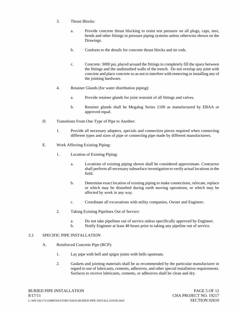
BURIED PIPE INSTALLATION PAGE 5 OF 12 8/17/11 CHA PROJECT NO. 19217 L:\WP\19217\COMPENSATORY\02610 BURIED PIPE INSTALLATION.DOC SECTION 02610
3. Thrust Blocks:
a. Provide concrete thrust blocking to resist test pressure on all plugs, caps, tees, bends and other fittings in pressure piping systems unless otherwise shown on the Drawings.
b. Conform to the details for concrete thrust blocks and tie rods.
c. Concrete: 3000 psi, placed around the fittings to completely fill the space between the fittings and the undisturbed walls of the trench. Do not overlap any joint with concrete and place concrete so as not to interfere with removing or installing any of the jointing hardware.
4. Retainer Glands (for water distribution piping):
a. Provide retainer glands for joint restraint of all fittings and valves. b. Retainer glands shall be Megalug Series 1100 as manufactured by EBAA or
approved equal.
D. Transitions From One Type of Pipe to Another:
1. Provide all necessary adapters, specials and connection pieces required when connecting different types and sizes of pipe or connecting pipe made by different manufacturers.
E. Work Affecting Existing Piping:
1. Location of Existing Piping:
a. Locations of existing piping shown shall be considered approximate. Contractor shall perform all necessary subsurface investigation to verify actual locations in the field.
b. Determine exact location of existing piping to make connections, relocate, replace
or which may be disturbed during earth moving operations, or which may be affected by work in any way.
c. Coordinate all excavations with utility companies, Owner and Engineer.
2. Taking Existing Pipelines Out of Service:
a. Do not take pipelines out of service unless specifically approved by Engineer. b. Notify Engineer at least 48 hours prior to taking any pipeline out of service.
3.3 SPECIFIC PIPE INSTALLATION
A. Reinforced Concrete Pipe (RCP):
1. Lay pipe with bell and spigot joints with bells upstream.
2. Gaskets and jointing materials shall be as recommended by the particular manufacturer in regard to use of lubricants, cements, adhesives, and other special installation requirements. Surfaces to receive lubricants, cements, or adhesives shall be clean and dry.
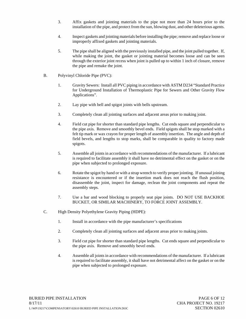
BURIED PIPE INSTALLATION PAGE 6 OF 12 8/17/11 CHA PROJECT NO. 19217 L:\WP\19217\COMPENSATORY\02610 BURIED PIPE INSTALLATION.DOC SECTION 02610
3. Affix gaskets and jointing materials to the pipe not more than 24 hours prior to the installation of the pipe, and protect from the sun, blowing dust, and other deleterious agents.
4. Inspect gaskets and jointing materials before installing the pipe; remove and replace loose or improperly affixed gaskets and jointing materials.
5. The pipe shall be aligned with the previously installed pipe, and the joint pulled together. If, while making the joint, the gasket or jointing material becomes loose and can be seen through the exterior joint recess when joint is pulled up to within 1 inch of closure, remove the pipe and remake the joint.
B. Polyvinyl Chloride Pipe (PVC):
1. Gravity Sewers: Install all PVC piping in accordance with ASTM D234 “Standard Practice for Underground Installation of Thermoplastic Pipe for Sewers and Other Gravity Flow Applications”.
2. Lay pipe with bell and spigot joints with bells upstream.
3. Completely clean all jointing surfaces and adjacent areas prior to making joint.
4. Field cut pipe for shorter than standard pipe lengths. Cut ends square and perpendicular to the pipe axis. Remove and smoothly bevel ends. Field spigots shall be stop marked with a felt tip mark or wax crayon for proper length of assembly insertion. The angle and depth of field bevels, and lengths to stop marks, shall be comparable in quality to factory made spigots.
5. Assemble all joints in accordance with recommendations of the manufacturer. If a lubricant is required to facilitate assembly it shall have no detrimental effect on the gasket or on the pipe when subjected to prolonged exposure.
6. Rotate the spigot by hand or with a strap wrench to verify proper jointing. If unusual joining resistance is encountered or if the insertion mark does not reach the flush position, disassemble the joint, inspect for damage, reclean the joint components and repeat the assembly steps.
7. Use a bar and wood blocking to properly seat pipe joints. DO NOT USE BACKHOE BUCKET, OR SIMILAR MACHINERY, TO FORCE JOINT ASSEMBLY.
C. High Density Polyethylene Gravity Piping (HDPE):
1. Install in accordance with the pipe manufacturer’s specifications
2. Completely clean all jointing surfaces and adjacent areas prior to making joints.
3. Field cut pipe for shorter than standard pipe lengths. Cut ends square and perpendicular to the pipe axis. Remove and smoothly bevel ends.
4. Assemble all joints in accordance with recommendations of the manufacturer. If a lubricant is required to facilitate assembly, it shall have not detrimental affect on the gasket or on the pipe when subjected to prolonged exposure.
BURIED PIPE INSTALLATION PAGE 7 OF 12 8/17/11 CHA PROJECT NO. 19217 L:\WP\19217\COMPENSATORY\02610 BURIED PIPE INSTALLATION.DOC SECTION 02610
3.4 FIELD QUALITY CONTROL
A. General:
1. Notify Engineer at least 48 hours in advance of all testing.
2. Provide all testing apparatus including pumps, hoses, gauges, fittings, temporary bulkheads, plugs, compressors and miscellaneous other required items.
3. Provide temporary blocking and bracing or approved thrust and joint restraint to prevent joint separation and pipe movement during testing.
4. Unless otherwise approved, conduct all tests in the presence of the Engineer and in the presence of local authorities having jurisdiction.
5. Water Source:
a. Provide all water for testing, flushing and other water uses. The source of the water shall be subject to the approval of the Engineer.
b. The point of introduction of water for conducting tests shall be subject to the
approval of the Engineer.
6. All costs for tests shall be included in the Contractor’s bid.
7. Locate, and repair or replace, section of piping which fail the test and retest until acceptance.
B. Required Tests for Gravity Sanitary Sewers:
1. Perform the following tests after all the sewer pipe has been installed and prior to final acceptance.
a. Deflection Test b. Alignment Test c. Low Pressure Air Test d. Corroborative Infiltration/Exfiltration Test e. Television Inspection, if required based on results of (c) and (d) above.
2. Perform tests prior to placement of pavement, or other construction which may, in the opinion of the Engineer, be detrimentally effected by excavation required for repairs.
3. Perform the tests only after the backfill has been in place to its full depth for a minimum of 30 days.
4. Submit details prior to making tests of proposed testing procedures with a description of methods and equipment to the Engineer for approval.
5. Deflection Test:
a. Deflection test all flexible sewer pipe with a “go/no-go” mandrel with a diameter equal to 95% of the inside diameter of the pipe.
b. Maximum pipe deflection: 5%.
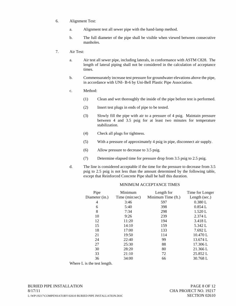
BURIED PIPE INSTALLATION PAGE 8 OF 12 8/17/11 CHA PROJECT NO. 19217 L:\WP\19217\COMPENSATORY\02610 BURIED PIPE INSTALLATION.DOC SECTION 02610
6. Alignment Test:
a. Alignment test all sewer pipe with the hand-lamp method.
b. The full diameter of the pipe shall be visible when viewed between consecutive manholes.
7. Air Test:
a. Air test all sewer pipe, including laterals, in conformance with ASTM C828. The length of lateral piping shall not be considered in the calculation of acceptance times.
b. Commensurately increase test pressure for groundwater elevations above the pipe, in accordance with UNI- B-6 by Uni-Bell Plastic Pipe Association.
c. Method:
(1) Clean and wet thoroughly the inside of the pipe before test is performed.
(2) Insert test plugs in ends of pipe to be tested.
(3) Slowly fill the pipe with air to a pressure of 4 psig. Maintain pressure between 4 and 3.5 psig for at least two minutes for temperature stabilization.
(4) Check all plugs for tightness.
(5) With a pressure of approximately 4 psig in pipe, disconnect air supply.
(6) Allow pressure to decrease to 3.5 psig.
(7) Determine elapsed time for pressure drop from 3.5 psig to 2.5 psig.
d. The line is considered acceptable if the time for the pressure to decrease from 3.5 psig to 2.5 psig is not less than the amount determined by the following table, except that Reinforced Concrete Pipe shall be half this duration.
MINIMUM ACCEPTANCE TIMES
Pipe Diameter (in.)
Minimum Time (min:sec)
Length for Minimum Time (ft.)
Time for Longer
Length (sec.) 4 6 8
10 12 15 18 21 24 27 30 33 36
3:46 5:40 7:34 9:26
11:20 14:10 17:00 19:50 22:40 25:30 28:20 21:10 34:00
597 398 298 239 194 159 133 114 99 88 80 72 66
0.380 L 0.854 L 1.520 L 2.374 L 3.418 L 5.342 L 7.692 L
10.470 L 13.674 L 17.306 L 21.366 L 25.852 L 30.768 L
Where L is the test length.

BURIED PIPE INSTALLATION PAGE 9 OF 12 8/17/11 CHA PROJECT NO. 19217 L:\WP\19217\COMPENSATORY\02610 BURIED PIPE INSTALLATION.DOC SECTION 02610
e. If the leakage in the section tested exceeds the specified amount, repair or replace the section tested to reduce the leakage to within the specified limits and repeat the test until the leakage requirements are met.
f. The Contractor may, at his option, infiltration/exfiltration test all sewer pipe in lieu
of the air test.
8. Corroborative Infiltration/Exfiltration Test:
a. Where air testing is used for leakage testing, corroborative infiltration/exfiltration testing shall be performed.
b. Test the three (3) sewer sections which indicate the greatest rate of air loss.
c. If the infiltration/exfiltration tests prove acceptable no additional testing is required;
however, if the air test is not verified by the corroborative testing, complete infiltration/exfiltration testing shall be required as the basis for final acceptance.
9. Infiltration Test: a. Use the infiltration test when groundwater levels are at least two feet above the top
of the pipe for the lengths of the section tested during the period of the tests. b. Measure leakage by a watertight well, weir, or other approved means installed at
the lower end of each section under test. c. Test for a period of at least 3 days. d. Total leakage of any section tested shall not exceed the rate of 200 or 50 gallons per
mile of pipe per 24 hours per inch of nominal internal diameter, for concrete and PVC pipe respectively.
e. If the leakage in the section tested exceeds the specified amount, repair or replace
the sections to reduce the leakage to within the specified limits and repeat until the leakage requirements are met.
10. Exfiltration Test:
a. Use the exfiltration test if the groundwater levels are less than two (2) feet above the top of the pipe for the lengths of the section tested during the period of the test.
b. Fill the pipe and manhole with water to provide a positive differential head of at
least two feet on the top of the pipe (or the top of the groundwater) at the highest point of the pipeline under test.
c. During exfiltration testing the maximum internal pipe pressure at the lowest end
shall not exceed 25 feet of water. d. The amount of water added to maintain this head shall be the leakage. e. Test for a period of at least four hours.

BURIED PIPE INSTALLATION PAGE 10 OF 12 8/17/11 CHA PROJECT NO. 19217 L:\WP\19217\COMPENSATORY\02610 BURIED PIPE INSTALLATION.DOC SECTION 02610
f. Total leakage of any section tested shall not exceed the rate of 200 gallons or 50 gallons per mile of pipe per 24 hours per inch of nominal internal diameter for concrete and PVC pipe respectively.
g. If the leakage in the section tested exceeds the specified amount, repair or replace
sections to reduce the leakage to within the specified limits and repeat the test until the leakage requirements is met.
h. On steep grades it may be necessary to place plugs in the pipe between manholes to
avoid excessive pressures in the sewer pipe and against the caps at the end of house and building connections.
11. Television Inspection:
a. If a section of sewer has failed the air and exfiltration/infiltration tests, or is proven poorly aligned by the lamp test, inspect the sewer by closed-circuit television to locate and repair defective section of sewer.
b. The Engineer will notify the Contractor in writing which completed sewers shall be
inspected by closed-circuit television and commence the television inspection within 15 days of the Engineer’s written notification.
c. Notify the Engineer at least 5 days prior to commencement of television inspection.
d. No television inspection shall be performed without the Engineer or his
representative present to witness the inspection.
e. Provide the Engineer with three (3) copies of a report of the televising inspection of each section of completed sewer inspected. Show the exact location and extent of all cracks, loose joints, holes, vertical and horizontal, misalignment, faulty service connections, caved-in pipe, points of infiltration, obstructions, debris and all else detrimental to the proper functioning and service of the completed sewer. Provide the actual television inspection video with the report showing all the above conditions found, at all wyes, tees and laterals and as directed by the Engineer. The Engineer will review the report and will instruct the Contractor, to repair any conditions which, in the opinion of the Engineer, are detrimental to the proper function and service of the sewer.
12. Visual Inspection: Prior to final acceptance, a visual inspection of all appurtenance structures, i.e. manholes, chambers, etc., will be required. Repair visual leaks, regardless of their magnitude.
C. Required Tests for Waterlines and Force Mains:
1. Perform the following after the pipe has been installed and prior to final acceptance:
a. Pressure Test. b. Leakage Test.
2. Presumptive hydrostatic tests may be performed when the system is partially backfilled to “check” the work, but final acceptance shall be based on hydrostatic tests performed on the finished system after it is completely backfilled.

BURIED PIPE INSTALLATION PAGE 11 OF 12 8/17/11 CHA PROJECT NO. 19217 L:\WP\19217\COMPENSATORY\02610 BURIED PIPE INSTALLATION.DOC SECTION 02610
3. Pressure Test:
a. Test piping to 1.5 times the pipe working pressure, or 150 psi, whichever is greater. Measure test pressures at the lowest point in the pipe section and correct to the elevation of the gauge.
b. Relieve trapped air at the section high points through hydrants, or taps installed for
this purpose, provided temporary installations are removed and plugged after acceptance.
c. Maintain the test pressure for a period of two (2) hours. At the end of the test
period, if the test pressure remains constant, the pipe section shall have passed the test. If the pressure has dropped, it shall be brought back to the test pressure by pumping a known volume of water (by pumping from a graduated container or by metering) back into the pipe. The volume of water thus used, representing leakage from the pipe, shall be recorded. If the leakage is less than the allowable leakage specified below, the pipe shall have passed the test. If the leakage exceeds the allowable leakage specified, the Contractor shall locate the leak, permanently repair the section of pipe where the leak is occurring to the satisfaction of the Engineer, and retest the pipe as specified above.
4. Leakage Test:
a. Conduct the leakage test concurrently with the pressure test. b. The maximum allowed leakage is determined by the following formula:
L = N x D x P1/2
7400
where L = allowable leakage, in gph where N = No. of joints in test section where D = nominal pipe diameter, in inches where P = average test pressure, in psig
5. Acceptance shall be determined on the basis of allowable leakage. If any pipe section discloses leakage greater than that specified, locate, repair and retest until the leakage is within the limits specified.
6. Make all visible leaks tight regardless of the amount of leakage, and if the lines do not meet the above leakage test, repair and retest as necessary until the leakage requirement is met. Repair or replace all defective work.
D. Disinfection of Potable Water Mains
1. Disinfect all potable water mains in accordance with the latest version of AWWA C651, except that the placement of chlorine powder or tablets inside the pipe during installation shall not be allowed. Disinfect water mains after the piping has passed the pressure and leakage testing.
2. Flush the pipe with water at a minimum velocity of 2.5 feet per second (fps) to clear all foreign material from the pipe.
3. Apply a chlorine solution with a concentration between 50 parts per million (ppm) and 100 ppm. The chlorine solution shall remain in the piping for a minimum of 24 hours. The

BURIED PIPE INSTALLATION PAGE 12 OF 12 8/17/11 CHA PROJECT NO. 19217 L:\WP\19217\COMPENSATORY\02610 BURIED PIPE INSTALLATION.DOC SECTION 02610
concentration at the end of this period shall be at least 25 ppm in all sections of the main. Repeat the entire procedure if the residual is less than 25 ppm.
a. While the chlorinated water is being added, all appurtenances (valves, hydrants,
etc.) shall be operated so as to completely disinfect the new work. b. Position valves so that the chlorine solution in the section being disinfected will not
flow into water mains in active service. c. Chlorine residual samples shall be taken as directed by the Engineer.
4. After the twenty four (24) hour retention period, flush the main until residual testing indicates that the chlorine concentration is approximately that of the neighboring service area.
a. Dispose of heavily chlorinated water into sanitary sewer or tank truck. b. The Owner and the owner of the sanitary sewer system shall be notified a minimum
of twenty-four (24) hours prior to the discharge of any water to the sanitary sewer. Contractor shall submit to the Engineer written confirmation that the owner of sanitary sewer system has approved the discharge of water to its sanitary sewer.
c. Under no circumstances will the emptying of water onto roadways, or into ditches,
culverts, streams or wetlands be allowed.
5. After disinfection and final flushing, and prior to placing the lines in service, the Contractor shall collect bacteriological samples (both coliform and heterotrophic plate count) and submit samples to an approved testing laboratory. Two consecutive sets of samples shall be taken at least 24 hours apart in accordance with AWWA C651. The collection points shall be as directed by the Engineer and local authority having jurisdiction.
a. The testing laboratory performing the bacteriological analysis shall be acceptable to
the Engineer. b. Submit three (3) copies of the laboratory analysis to the Engineer. c. Should safe results not occur after laboratory tests, the Contractor shall, at his
expense, repeat the disinfection procedure until safe results are obtained. This includes a positive result for coliform or a measured heterotrophic plate count of greater than 500 colony-forming units per ML.
d. Contractor shall pay for all testing required.
6. All precaution shall be taken to maintain dry and sanitary conditions and prevent contamination of any piping. If, in the opinion of the Engineer, contamination has occurred, the Contractor shall repeat the disinfection procedure and testing at his cost and expense.
END OF SECTION
HIGH DENSITY POLYETHYLENE PIPE PAGE 1 OF 3 8/17/11 CHA PROJECT NO. 19217 L:\WP\19217\COMPENSATORY\02619 HIGH DENSITY POLYETHYLENE PIPE.DOC SECTION 02619
SECTION 02619 HIGH DENSITY POLYETHYLENE PIPE PART 1 - GENERAL 1.1 SUMMARY
A. This Section includes the installation of polyethylene piping systems as shown on the Drawings and as specified herein.
B. All piping, fittings, and appurtenances shall be new, clean and in accordance with material
specifications. In no instance shall second- hand or damaged materials be acceptable. 1.2 QUALITY ASSURANCE
A. Reference Standards:
1. The latest edition of the following standards, as referenced herein, shall be applicable.
a. “Standard Specifications, Construction and Materials, New York State Department of Transportation, Office of Engineering.”
b. “Standard Specifications for Highway Materials and Methods of Sampling and
Testing, American Association of State Highway and Transportation Officials (AASHTO).”
c. American Society of Testing and Materials (ASTM).
1.3 SUBMITTALS
A. Product Data:
1. Submit manufacturer’s catalog cuts, specifications and installation instructions, for both pipe and coupling system.
2. Submit manufacturer’s certification that product was manufactured, tested, and supplied in
accordance with the standards specified herein. 1.4 PRODUCT DELIVERY, STORAGE, AND HANDLING
A. Delivery and Storage:
1. Pipe, fittings, specials, appurtenances and accessories shall be delivered to and stored within the Contractor’s work limits as shown on the Drawings.
2. Special care shall be exercised during delivery and storage to avoid damage to the products.
3. Products shall be stored so as to avoid unnecessary handling and in locations where they will
not interfere with the Owner’s operations or public travel.
B. Handling:
1. Pipe, fittings, special appurtenances and accessories shall be handled carefully with approved handling devices in strict conformance with the manufacturer’s recommendations.

HIGH DENSITY POLYETHYLENE PIPE PAGE 2 OF 3 8/17/11 CHA PROJECT NO. 19217 L:\WP\19217\COMPENSATORY\02619 HIGH DENSITY POLYETHYLENE PIPE.DOC SECTION 02619
2. Products shall not be dropped nor shall products be otherwise dragged, rolled or skidded.
C. Products cracked, gouged, chipped, dented or otherwise damaged will not be approved and shall be removed and replaced at the Contractor’s expense, unless the product can be repaired in a manner acceptable to the manufacturer and Engineer. All repairs shall be at the Contractor’s expense.
PART 2 - PRODUCTS 2.1 MATERIALS
A. HDPE Water Tight Pipe:
1. Pipe shall be ADS N-12 WT IB (per AASHTO) smooth interior with annular exterior corrugations and a Manning’s “n” value of 0.012 high-density polyethylene pipe (HDPE) as manufactured by Advanced Drainage Systems (ADS), or approved equal. Pipe shall have an integral water tight gasketed bell and spigot, or approved equal.
a. 4 inch through 11 inches conforming to AASHTO M252 Type S
b. 12 inches through 60 inches conforming to AASHTO M294 Type S or ASTM F2306.
2. 4- through 60-inch (100 to 1500 mm) shall be watertight according to the requirements of ASTM D3212. Gaskets shall be made of polyisoprene meeting the requirements of ASTM F477. Gaskets shall be installed by the pipe manufacturer and covered with a removable, protective wrap to ensure the gasket is free from debris. A joint lubricant available from the manufacturer shall be used on the gasket and bell during assembly12- through 60-inch (300 to 1500 mm) diameters shall have a reinforced bell with a bell tolerance device. The bell tolerance device shall be installed by the manufacturer.
3. Fittings shall conform to ASTM F 2306. Bell and spigot connections shall utilize a spun-on or welded bell and valley or saddle gasket meeting the water-tight joint performance requirements of ASTM F 2306.
B. Flared End Section:
1. Flared end sections shall be 1210 NP or 1810 NP HDPE end sections as manufactured by ADS, or equal.
2. End sections shall be fastened to the last corrugation of the pipe length using a high strength nylon cable tie supplied by the manufacturer through pre-drilled holes at the top of the end section collar.
PART 3 - EXECUTION 3.1 INSPECTION
A. Inspect all pipe and fittings prior to laying in the trench. Remove defective pipe and fittings from the site.
B. Do not backfill until inspection by the Engineer, unless otherwise approved by the Engineer.

HIGH DENSITY POLYETHYLENE PIPE PAGE 3 OF 3 8/17/11 CHA PROJECT NO. 19217 L:\WP\19217\COMPENSATORY\02619 HIGH DENSITY POLYETHYLENE PIPE.DOC SECTION 02619
3.2 INSTALLATION AND TESTING
A. Trenching, backfilling and compaction shall conform to Section “Trenching and Backfilling.”
B. Pipe installation and testing shall conform to Section “Buried Pipe Installation.” END OF SECTION


TOPSOIL PAGE 1 OF 4 8/17/11 CHA PROJECT NO. 19217 L:\WP\19217\Compensatory\02920 Topsoil.doc SECTION 02920
SECTION 02920 TOPSOIL
PART 1 - GENERAL
1.1 SUMMARY
A. This section includes provisions for the placement of topsoil in conformance with the lines, grades and thicknesses as shown on the Drawings and as herein specified.
B. Minimum thickness is six (6) inches, for all areas disturbed during construction and not receiving other surface treatment.
C. The Contractor shall furnish all materials and perform all work in accordance with these specifications, drawings, and instructions provided by the Owner.
1.2 SUBMITTALS
A. Samples: Furnish earth materials to the testing laboratory for analysis and report, as directed by the Engineer or as outlined in the specifications.
B. Quality Control Submittals:
1. Test Reports: The testing laboratory shall submit written reports of all tests, investigations, and recommendations to the Contractor and the Engineer. Indicate quantities of materials necessary to bring topsoil into compliance with textural/gradation requirements. Indicate quantity of lime and quantity and analysis of fertilizer.
1.3 REFERENCES
A. Comply with the latest edition of the following standards:
1. “Standard Specifications, Construction and Materials, New York State Department of Transportation, Office of Engineering.”
2. “Standard Specifications for Highway Materials and Methods of Sampling and Testing, American Association of State Highway and Transportation Officials (AASHTO).”
3. ASTM International (ASTM)
a. C33, Standard Specification for Concrete Aggregates. b. C602, Standard Specification for Agricultural Liming Materials
4. U.S. Bureau of Reclamation (USBR)
a. 514.4.4, Reclamation Instructions, Series 510—Land Classification Techniques and Standards, Part 514—Laboratory Procedures, Chapter 4—Particle-Size Analyses.
b. 14.8.7, Reclamation Instructions, Series 510—Land Classification Techniques and Standards, Part 514—Laboratory Procedures, Chapter 8—Soil Chemical Tests
1.4 QUALITY ASSURANCE
A. Provide and pay for all costs in connection with an approved independent testing facility to determine conformance of soils and aggregate with the specifications.

TOPSOIL PAGE 2 OF 4 8/17/11 CHA PROJECT NO. 19217 L:\WP\19217\Compensatory\02920 Topsoil.doc SECTION 02920
1.5 PROJECT CONDITIONS
A. Coordinate the placement of topsoil with the completion of all underground work including that of the other trades.
PART 2 - PRODUCTS
2.1 MATERIALS
A. Topsoil: Natural, friable, fertile, fine loamy soil possessing the characteristics of representative topsoils in the vicinity which produces a heavy growth; free from subsoil, objectionable weeds, litter, sods, stiff clay, stones larger than 1 inch in diameter, stumps, roots, trash, toxic substances, or any other material which may be harmful to plant growth or hinder planting operations. Contractor is to verify amount stockpiled and supply any additional as needed:
1. Topsoil shall contain not less than 6% nor more than 20% organic matter as determined by the wet combustion method (chronic acid reduction); topsoil shall have a pH value of not less than 5.5 nor more than 7.0;
2. Topsoil shall meet the following mechanical analysis:
Size of Screen % of Soil Retained % of Soil Passing 1” 0 100 1/4 3 97
No. 100 40-60 40-60
3. Imported topsoil in which more than 60% of the material passing a No. 100 sieve shall be rejected. All percentages are to be based on the dry weight of the samples.
4. Laboratory tests of the topsoil shall be performed by a certified testing laboratory, and shall perform tests for the following:
a. Sieve particle size analysis and gradient of mineral content
b. Chemical analysis of the following:
(1) pH and buffer pH
(2) percent of organic content
(3) nutrient levels of phosphorus, potassium magnesium, manganese, iron, zinc and calcium
(4) soluble salt
(5) cation exchange capacity (CEC)
c. Recommended fertilizer and rate of application for low and medium level nutrient soils.
2.2 MATERIAL ACCEPTANCE
A. Topsoil may be acquired from approved sites that are designated on the Drawings. If no sites are designated, material proposed for use as topsoil must be stockpiled, sampled, and tested prior to use.

TOPSOIL PAGE 3 OF 4 8/17/11 CHA PROJECT NO. 19217 L:\WP\19217\Compensatory\02920 Topsoil.doc SECTION 02920
B. Topsoil containing foreign material may be rejected on the basis of visual examination by the Engineer, prior to testing.
C. Acceptance of topsoil shall be based upon test results. Tested topsoil must be approved in writing by the Engineer before any material is used.
2.3 SOIL AMENDMENT
A. Textural Amendments: Amend as necessary to conform to required composition by incorporating sand, peat, manure, or sawdust
B. Fertilizer: Shall be delivered to the site, mixed as specified, in the original unopened standard size bags showing weight, analysis and name of manufacturer. Store fertilizer in a weatherproof place and in such a manner that it shall be kept dry and its effectiveness shall not be impaired.
1. Percentages of nitrogen, phosphorus and potash shall be based on laboratory test recommendations. For the purpose of bidding, assume 10% nitrogen, 6% phosphorus and 4% potash by weight. At least 50% of the total nitrogen shall contain no less than 3% water-insoluble nitrogen. At least 60% of the nitrogen content shall be derived from super-phosphate containing not less than 18% phosphoric acid or bone meal containing 25% - 30% phosphoric acid and 2% - 3% nitrogen. Potash shall be derived from muriate of potash containing 55% - 60% potash.
2. Grass or sodded areas shall have fertilizer applied according to soil text report or as specified on the drawings.
C. Organic Matter: Leaf matter and yard waste composted sufficiently to break down all woody fibers, seeds, and leaf structures, and free of toxic and non-organic matter. Organic matter shall be commercially prepared compost. Coarse sand shall be clean, sharp, natural sands free of limestone, shale and slate particles, ASTM C-33 fine aggregate with a Fines Modulus Index of 2.75 or greater.
D. Lime: Shall be ground palletized, or pulverized lime manufactured to meet agricultural standards and contain a maximum of 60 percent oxide.
PART 3 - EXECUTION
3.1 STOCKPILING
A. Stockpile topsoil from on-site sources or provide from off-site sources and stockpile, if on-site quantities are deficient.
B. Stockpiles are to contain not less than 200 cu. yds. or the minimum required for the project.
C. Stockpiles are to have a height of at least 4' and be trimmed to uniform surfaces and slopes.
D. The sites of all stockpiles and adjacent areas, which have been disturbed are to be graded and put into an acceptable condition by seeding, as directed by the Engineer.
3.2 PREPARATION
A. Preparation - Disk, drag, harrow or hand rake subgrade to a depth of 3 inches to provide bond for topsoil. Topsoil, which must be transported across finished walks, shall be delivered in such a manner that no damage will be done to the walks. The Contractor shall be responsible for the repair of such damage.

TOPSOIL PAGE 4 OF 4 8/17/11 CHA PROJECT NO. 19217 L:\WP\19217\Compensatory\02920 Topsoil.doc SECTION 02920
B. Before placing topsoil, rake subsoil surface clear of stones larger than 1½ inches, debris, and roots. Compact topsoil to form a layer with minimum depth of 4 inches in lawn areas and 12 inches in shrub beds. Topsoil shall be placed so that after final settlement there will be good drainage (and conforming to elevations shown on drawings). Contractor is to maintain surfaces and place any additional topsoil necessary to replace that which may have eroded before acceptance.
C. Locations containing unsuitable subsoil shall be treated in one of the following manners:
1. Where unsuitability within the construction site is deemed by the Owner to be due to excessive compaction caused by heavy equipment or by the presence of boards, mortar, concrete or other construction materials in subgrade, and where the natural subsoil is other than A.A.S.H.T.O. classification of A6 or 7, the Contractor shall loosen such areas with spikes, discs, or other means to loosen the soil to a condition acceptable by the Owner. The Contractor shall also remove all debris and objectionable material. Soil should be loosened to a minimal depth of 12 inches with additional loosening as required to obtain adequate drainage. Contractor may introduce peat moss, sand, or organic matter into the subsoil to obtain adequate drainage should he so desire. All such remedial measures shall be considered as incidental to the work and no extra payment shall be made for this part of the work; and,
2. Where subgrade is deemed by the Owner to be unsuitable because the natural subsoil falls into an AASHTO classification of A6 or 7 and contains moisture in excess of 30%, then such a condition shall be rendered suitable by installation of a subdrainage system or by other means described elsewhere in these specifications. Where such conditions have not been known or revealed prior to planting time and where they have not been recognized in the preparation of drawings and specifications, then the Owner shall issue a change order to install the proper remedial measures, all of which shall be in addition to the contract sum.
3.3 TOPSOIL PLACEMENT
A. Do not place topsoil when subsoil or topsoil is frozen, excessively wet, or otherwise detrimental to the Work.
B. Mix soil amendments, lime, and fertilizer with topsoil before placement or spread on topsoil surface and mix thoroughly into entire depth of topsoil before planting or seeding. Delay mixing of fertilizer if planting or seeding will not occur within 3 days.
C. Place 1/2 of total depth of topsoil and work into subgrade soil to create a transition layer. Place remainder of topsoil to depth after compacting to 75 percent where seeding and planting are scheduled.
D. Uniformly distribute to within 1/2 inch of final grades. Fine grade topsoil eliminating rough or low areas and maintaining levels, profiles, and contours of subgrade to ensure positive drainage.
E. Remove stones exceeding 1 inch, roots, sticks, debris, and foreign matter during and after topsoil placement.
F. Remove surplus subsoil and topsoil from Site. Grade stockpile area as necessary and place in condition acceptable for planting or seeding.
3.4 CLEANING
A. Remove all surplus subsoil and topsoil from project site.
B. Leave the site in clean, satisfactory condition ready to receive subsequent operations.
END OF SECTION

SEEDING PAGE 1 OF 5 8/17/11 CHA PROJECT NO. 19217 L:\WP\19217\Compensatory\02930 Seeding.doc SECTION 02930
SECTION 02930 SEEDING
PART 1 - GENERAL
1.1 SUMMARY
A. This Section includes the preparation of ground surfaces, fertilization of applicable areas, seeding, mulching of applicable surface areas, and maintenance of turf areas until such time as project is accepted by Engineer. Applicable areas shall include those identified on the Contract Drawings.
B. Seed shall be sown from April 1 to June 15, or from August 15 to October 15 of given calendar year, unless otherwise approved by Engineer.
1.2 SUBMITTALS
A. Quality Control Submittals:
1. Certification:
a. Submit manufacturer’s or vendor’s certified analysis for soil amendments and fertilizer materials.
b. Submit vendor’s certified analysis for each grass seed mixture required, stating botanical and common name, percentages by weight, percentages by purity, germination, and weed seed.
B. Maintenance Instructions: Submit instructions recommending procedures to be implemented for maintenance of landscaped work for one (1) full year. Submit prior to expiration of Contractor’s maintenance period.
C. Submit description of planned mulching techniques and corresponding manufacturer’s installation recommendations for approval by Engineer.
1.3 QUALITY ASSURANCE
A. All turf and grasses work shall be performed by one Contractor, with proven expertise in this type of construction.
B. Package standard products with the manufacturer’s certified analysis. For other materials, provide analysis by recognized laboratory made in accordance with methods established by the Association of Official Agriculture Chemists, wherever applicable.
C. The Contractor shall provide and pay for all costs in connection with an approved independent testing facility to determine conformance of materials with the specifications.
1.4 DELIVERY, STORAGE, AND HANDLING
A. Deliver packaged materials in containers, showing weight, analysis, and name of manufacturer. Protect materials from deterioration during delivery, and while stored on site.

SEEDING PAGE 2 OF 5 8/17/11 CHA PROJECT NO. 19217 L:\WP\19217\Compensatory\02930 Seeding.doc SECTION 02930
PART 2 - PRODUCTS
2.1 MATERIALS
A. Fertilizer:
1. Commercial fertilizer (5-10-5) inorganic, or organic, containing not less than five (5) percent nitrogen, ten (10) percent available phosphoric acid, and five (5) percent water soluble potash.
2. If, as an alternative, the Contractor wishes to substitute for commercial fertilizer 5-10-5, another commercial fertilizer with a 1-2-1 ratio, such as 10-20-10 or 6-12-6, they may do so with the approval of the Engineer and the rate of fertilizer to be used shall be whatever amount is required to furnish the same amount of nitrogen as would be supplied by the 5-10-5.
B. Seed:
1. Seed shall be fresh, clean, new-crop seed mixed in the proportions specified for species and variety, conforming to Federal and State Standards.
2. Use the following seed mix: Species Application
Rate % By Purity % By Germination
Riverbank Wild Rye – Elymus Riparius
4 lbs/1,000 sf 95 85
Virginia Wild Rye – Elymus Virginicus
4 lbs/1,000 sf 95 85
3. Weed seed content shall not exceed 0.25%.
C. Mulch:
1. Provide and install a mulch adequate to protect the seeding during its growing period. It shall be the responsibility of the Contractor to determine the appropriate mulching techniques for the particular site conditions and acquire approval of the same from the Engineer.
2. Clean straw for gentle slopes, consisting of stalks of oats, wheat, rye, or other approved crops which are free of noxious weed seeds. Weight shall be based on a fifteen (15) percent moisture content.
3. Mulching blanket for steep slopes and drainage swales: “Curlex Blanket” by American Excelsior, “Ero-Mat” by Contech Construction Products, Inc, or approved equal.
D. Water: Clean and potable.
2.2 ACCESSORIES
A. Soil Amendments: Soil amendments are not to be made without review and authorization by the Engineer.
1. Lime: Natural limestone containing not less than 85% of total carbonates, ground so that not less than 90% passes a 10-mesh sieve and not less than 50% passes a 100-mesh sieve.

SEEDING PAGE 3 OF 5 8/17/11 CHA PROJECT NO. 19217 L:\WP\19217\Compensatory\02930 Seeding.doc SECTION 02930
2. Aluminum Sulfate: Commercial grade.
3. Peat Humus: FS Q-P-166 and with texture and pH range suitable for intended use.
4. Bonemeal: Commercial, raw, finely ground; 4% nitrogen and 20% phosphoric acid.
5. Superphosphate: Soluble mixture of treated minerals; 20% available phosphoric acid.
6. Sand: Clean, washed sand, free of toxic materials.
7. Perlite: Conforming to National Bureau of Standards PS 23.
8. Vermiculite: Horticultural grade, free of toxic substances.
9. Sawdust: Rotted sawdust, free of chips, stones, sticks, soil, or toxic substances and with 7.5 pounds (2.8 kg) nitrogen uniformly mixed into each cubic yard of sawdust.
10. Manure: Well rotted, unleached stable or cattle manure containing not more than 25% by volume of straw, sawdust, or other bedding materials and containing no chemicals or ingredients harmful to plants.
11. Commercial Fertilizer: Complete fertilizer of neutral character, with some elements derived from organic sources and containing available plant nutrients.
12. Composted Organic Material: Shall have a minimum organic matter content of 60 percent, as determined by ASTM D-2974, and screened to ¾-inch (1.9 cm).
PART 3 - EXECUTION
3.1 PREPARATION OF TOPSOIL
A. Clean topsoil of roots, plants, stones, clay lumps and other extraneous materials harmful or toxic to plant growth.
B. Mix fertilizer into top 2 inches (5 cm) of topsoil at a rate of 10 pounds (3.7 kg) per 1,000 square feet. (92.9 m2)
C. Mix approved soil amendments into top 2 inches (5cm) of topsoil at necessary rates.
D. Water dry topsoil to depth of 4 inches (10cm) at least 48 hours prior to seeding to obtain a loose friable seed bed.
3.2 PREPARATION OF UNCHANGED GRADES
A. Where lawns are to planted in areas not altered or disturbed by excavating, grading, or stripping, prepare soil for seeding as follows:
1. Till to a depth of not less than 6 inches (15cm).
2. Apply soil amendments and initial fertilizers as specified.
3. Remove high areas and fill in depressions.

SEEDING PAGE 4 OF 5 8/17/11 CHA PROJECT NO. 19217 L:\WP\19217\Compensatory\02930 Seeding.doc SECTION 02930
4. Till soil to a homogeneous mixture of fine texture, free of lumps, clods, stones, roots, and other extraneous matter.
a. Prior to preparation of unchanged areas, remove existing grass, vegetation and turf. Dispose of such materials off the site; do not turn over into soil being prepared for lawns.
b. Apply specified commercial fertilizer at rates specified and thoroughly mixed into upper 2 inches (5 cm) of topsoil. Delay application of fertilizer, if lawn planting will not follow within one week.
3.3 SEEDING
A. Apply seed only when wind velocities are less than five (5) miles per hour (9km/hr).
B. Sow half the seed with mechanical seeder.
C. Sow remaining half of the seed at right angles to the direction of the first seeding pattern, using the same method.
D. Apply seed at the rate of 4 pounds (1.5 kg) per 1,000 square feet (92.9 sq. meters) of disturbed area.
E. Cover seed to a depth of ⅛-inch (3mm) by raking, harrowing, or cultipacking.
F. Roll seeded area with roller weighing no more than 150 pounds per foot of roller width.
G. Water seeded areas to a depth of four (4) inches (10cm) as required during the maintenance period.
3.4 MULCHING
A. Spread straw uniformly over seeded area with 75% ground coverage and at least 1-½ inches loose depth.
1. If, in the opinion of the Engineer, wind will disrupt the mulching, apply asphalt emulsion at a rate of 10 gallons (37.81) per 1,000 square feet (92.9 m2).
B. Place mulching blanket in accordance with submitted manufacturer’s recommendations.
C. Place bonded fiber matrix mulch material, EcoAegis, at a rate of 3,500 to 4,100 pounds per acre, based on manufacturer’s recommendations.
3.5 HYDROSEEDING
A. Mix specified seed, fertilizer, and pulverized mulch in water, using equipment specifically designed for hydroseed application. Continue mixing until uniformly blended into homogeneous slurry suitable for hydraulic application.
B. Apply slurry uniformly to all areas to be seeded. Rate of application as required to obtain specified seed sowing rate.

SEEDING PAGE 5 OF 5 8/17/11 CHA PROJECT NO. 19217 L:\WP\19217\Compensatory\02930 Seeding.doc SECTION 02930
3.6 PROTECTION
A. Immediately after seeding, erect barricades and warning signs as required to protect newly planted areas from pedestrian and vehicular traffic. Maintain barricades throughout maintenance period until grass and/or turf is established.
B. Repair or replace damaged landscape work as directed by Engineer.
3.7 MAINTENANCE
A. Begin maintenance immediately after seed placement.
B. Watering:
1. Keep soil moist during seed germination period.
2. Supplement rainfall to produce a total depth penetration of 2 inches per day after germination.
3. Prevent erosion and displacement of seed.
C. Mowing:
1. When grass reaches 4 inches in height, mow to 2-½ inches in height.
2. Maintain grass between 1-½ inches and 2-½ inches in height.
3. Do not cut off more than 30% of grass leaf in a single mowing.
4. Remove grass clippings.
D. Reseed and mulch spots larger than 1 square foot not having uniform coverage.
E. Maintain lawns by watering, fertilizing, weeding, mowing, trimming, and other operations such as rolling, regardening, and replanting as required to establish a smooth, acceptable lawn, free of eroded or bare areas.
F. Maintain and protect all seeded areas until final acceptance of the Contract. Final acceptance of “Seeding” will not be made until an acceptable uniform stand of grass is obtained in all new lawn areas, except that the Engineer at their discretion may accept a portion or portions of the “Seeding” at various times. Upon acceptance by the Engineer of a seeded area, the Owner will immediately assume responsibility for maintenance and protection of that portion of the Contract Seeding.
END OF SECTION


SURFACE RESTORATION AND REPAIR PAGE 1 OF 2 8/17/11 CHA PROJECT NO. 19217 L:\WP\19217\Compensatory\02990 Surface Restoration and Repair.doc SECTION 02990
SECTION 02990 SURFACE RESTORATION AND REPAIR PART 1 - GENERAL 1.1 SUMMARY
A. This Section includes provisions for the restoration and repair of all disturbed surfaces, as shown on the Drawings, and as specified herein.
B. In general, the Contractor shall be responsible for leaving the Work site in an equal or better
condition than it exists prior to construction. This work shall include, but is not necessarily limited to, restoration and repair of the following items:
1. Sidewalks 2. Curbs 3. Driveways 4. Lawns 5. Trees and Planting 6. Retaining Walls 7. Monuments 8. Any others encountered and disturbed by construction.
PART 2 - PRODUCTS 2.1 MATERIALS
A. Sidewalks:
1. Concrete sidewalks shall be replaced in conformance with NYSDOT Section 608 “Sidewalks, Driveways, Bicycle Paths and Vegetation Control Strips.”
B. Curbs:
1. Curbs shall be replaced in conformance with NYSDOT Section 609 “Curb and Curb &
Gutter.”
2. Granite and stone curbs shall be reset.
C. Driveways:
1. Asphalt driveways shall be replaced to their existing thicknesses, but not less than 2 inches, in accordance with Section NYSDOT Section 608 “Sidewalks, Driveways, Bicycle Paths and Vegetation Control Strips.”
2. Crushed stone and gravel driveways shall be replaced to their existing thicknesses, but not
less than 2 inches.
D. Lawns:
1. Lawns shall be restored in conformance with Sections “Topsoil” and “Seeding.”

SURFACE RESTORATION AND REPAIR PAGE 2 OF 2 8/17/11 CHA PROJECT NO. 19217 L:\WP\19217\Compensatory\02990 Surface Restoration and Repair.doc SECTION 02990
E. Miscellaneous Items:
1. Monuments, flagpoles, retaining walls, etc., shall be removed in such a manner so as to
prevent damage, and be reset or reconstructed in their original locations unless otherwise directed by the Engineer. Damages incurred shall be corrected, or the item replaced, at the discretion of the Engineer.
PART 3 - EXECUTION 3.1 INSTALLATION
A. Remove all items designated to be reset or reused in a manner to prevent damage. Replace all damaged items with an equal material as approved by the Engineer, at the Contractor’s expense.
B. All methods and materials are subject to the approval of the Engineer.
C. Restore or repair to their original condition, or as otherwise specified herein, all surfaces damaged or
removed in the Work.
D. Roadway pavement replacement is specified in Section “Hot Mix Asphalt Paving.” END OF SECTION