HALT Service Information - Professional...
9
1 1601 North A. W. Grime, Suite B Round Rock, TX 78665 e-mail: [email protected] (512)244-3371 Fax: (512)244-1846 HALT Service Information Revision: 09/08/2008 Table of Contents: 1.0 Test Overview ......................................................................................................................... 2 1.1 Test Types / Sequence ....................................................................................................... 2 1.2 Test Equipment / Controllable Variables ............................................................................. 3 1.3 Test Set-Up......................................................................................................................... 3 1.4 Functional Test during HALT .............................................................................................. 4 1.5 Sample Size........................................................................................................................ 5 1.6 Failure(s) during HALT........................................................................................................ 5 2.0 Service Cost............................................................................................................................ 6 3.0 Check List ............................................................................................................................... 7 4.0 Appendix ................................................................................................................................. 8 4.1 Detailed Description of Each Test Type .............................................................................. 8 4.2 Definitions: Operational / Destruct Limit .............................................................................. 9 List of Tables / Pictures / Figures: Table 1: Graphical Overview of HALT ................................................................................................. 2 Table 3: HALT Check List ................................................................................................................... 7 Picture 1: HALT Chamber ................................................................................................................... 3 Picture 2: Fixture Examples (In-house/Client developed) ................................................................... 4 Figure 1: HALT Table Hole Pattern ..................................................................................................... 4 Figure 2: Definitions: Operational / Destruct Limit ............................................................................... 9
Transcript of HALT Service Information - Professional...

1
1601 North A. W. Grime, Suite B Round Rock, TX 78665 e-mail: [email protected] (512)244-3371 Fax: (512)244-1846
HALT Service Information
Revision: 09/08/2008 Table of Contents: 1.0 Test Overview......................................................................................................................... 2
1.1 Test Types / Sequence ....................................................................................................... 2 1.2 Test Equipment / Controllable Variables............................................................................. 3 1.3 Test Set-Up......................................................................................................................... 3 1.4 Functional Test during HALT .............................................................................................. 4 1.5 Sample Size........................................................................................................................ 5 1.6 Failure(s) during HALT........................................................................................................ 5
2.0 Service Cost............................................................................................................................ 6 3.0 Check List ............................................................................................................................... 7 4.0 Appendix................................................................................................................................. 8
4.1 Detailed Description of Each Test Type.............................................................................. 8 4.2 Definitions: Operational / Destruct Limit.............................................................................. 9
List of Tables / Pictures / Figures: Table 1: Graphical Overview of HALT................................................................................................. 2 Table 3: HALT Check List ................................................................................................................... 7 Picture 1: HALT Chamber ................................................................................................................... 3 Picture 2: Fixture Examples (In-house/Client developed) ................................................................... 4 Figure 1: HALT Table Hole Pattern ..................................................................................................... 4 Figure 2: Definitions: Operational / Destruct Limit ............................................................................... 9

2
1.0 Test Overview 1.1 Test Types / Sequence HALT (Highly Accelerated Life Test) generally consists of following 5 types of tests, which are sequentially performed, in order to determine the operating and destruct limits of the products with respect to temperature, vibration, and/or combination of the two.
• Cold Step-Stress (CSS) test • Hot Step-Stress (HSS) test • Rapid Thermal Transition (RTT) test • Vibration Step-Stress (VSS) test • Combined Environment (CE) test
Detailed descriptions of each test type are provided in Appendix. Although this is a highly-recommended test types/sequence, different test type/sequence/profile can be accommodated based on client’s specific requirements (expected application condition, time, cost, and existing experimental data).
Table 1: Graphical Overview of HALT

3
1.2 Test Equipment / Controllable Variables HALT will be conducted using a 30”x30”x30” Qualmark HALT chamber (OVS-2.5C, Picture 1). Product which weighs less than 100lb would be an ideal candidate for this test.
Controllable variables in HALT are: • Temperature -100C to 200C1, change rate of 50C/min1 • Vibration (Total Grms level over 10~10000Hz): 2Grms to 70Grms1
o It is a multi-axis (6 degree-of-freedom) repetitive shock and there is no capability to control characteristics of spectrum.
Note 1: This limit may be reduced in case of products with high mass.
Picture 1: HALT Chamber
Rapid cooling (up to 50C/min) is achieved by using liquid nitrogen boost. It is to note that Humidity is NOT-controlled as an input variable during HALT.
1.3 Test Set-Up To perform a sequence of above-mentioned tests, one or more products will be mounted on the vibration table (inside a chamber) at a time, with the airflow duct directed onto the test articles.
Pictures below describe the example of how the product is mounted to the table. Since HALT is a stimulation test (not simulation test), simple and light fixture, which transmits thermal/vibration energy efficiently to product, is preferred.

4
Picture 2: Fixture Examples (In-house/Client developed)
In the case of non-standard shape product (e.g., cylindrical, EUT with various extrusion features), we request client to prepare a holding fixture for the test, according to the vibration table-hole drawings (Figure 1).
Figure 1: HALT Table Hole Pattern
Furthermore, in case that multiple samples are to be tested simultaneously, non-uniformity nature of the HALT vibration table should be taken into consideration. Response of each sample to input vibration stress can be characterized with the use of accelerometers, prior to the beginning of the test.
5 thermocouples (can be increased up to 20 with the use of data logger) and 4 accelerometers are readily available to continuously monitor/record the product response against chamber set-points during HALT. It is advisable for client to determine the preferable locations of the thermocouple/accelerometer attachment within the test article. Feasibility of sensor attachment to the product (e.g., removal of enclosure, shorting of components) should be clarified prior to test.
1.4 Functional Test during HALT It is highly-recommended that the test articles would be fully operational throughout the HALT. Any necessary equipment to operate the EUT or perform functional test will be located outside of the chamber. Connecting cables are fed through the port (cables approximately ≥6 feet in length would be recommended) to the test article inside the chamber. Basic performance of the product as well as any

5
parameter changes during stress will be monitored, as per product specific requirements. Application of more than one power cycling is often practiced at the end of each dwell.
Although Professional Testing will make available our various pieces of test equipment (e.g., data-logger, power supply, voltmeter) for your use during the HALT service, notification of a list of necessary equipment to operate and verify the functionality of the test article to PTI would ensure a smooth implementation of HALT.
1.5 Sample Size It is recommended that 3 to 6 functional samples would be available for HALT. This allows exploration of destruct limit and/or conducting each test without any prior stress accumulation.
However, in practical sense, it is often a difficult proposition to prepare a number of samples at early product development cycle. By using spare parts/repairing parts on-sites, it is manageable to go through HALT with one system. This process can be feasible only when an engineer who is familiar with the design of the product is present during HALT. Regardless of necessity of repair during HALT, it is strongly recommended the representative engineer would witness the tests for maximum efficiency.
1.6 Failure(s) during HALT Each time a failure occurs, the product should be examined for root cause of failure. Once the root cause of failure is determined (if possible, with the help of representative engineer), it will be fixed and placed back inside the chamber to continue with step stressing. If multiple test articles are available, test can be resumed with a new test article, while a detailed failure analysis will be performed at client’s site on a later time.
The HALT process alone will not improve the reliability of the product. The root cause of the failures noted need to be determined and the problems corrected until the fundamental limit of the technology for the product can be reached. This process will yield the widest possible margin between product capabilities and the environment in which it will operate, thus increasing the product’s reliability, reducing the number of field returns and realizing long-term savings.

6
2.0 Service Cost
Contact Professional Testing for a Service Cost Proposal.
7
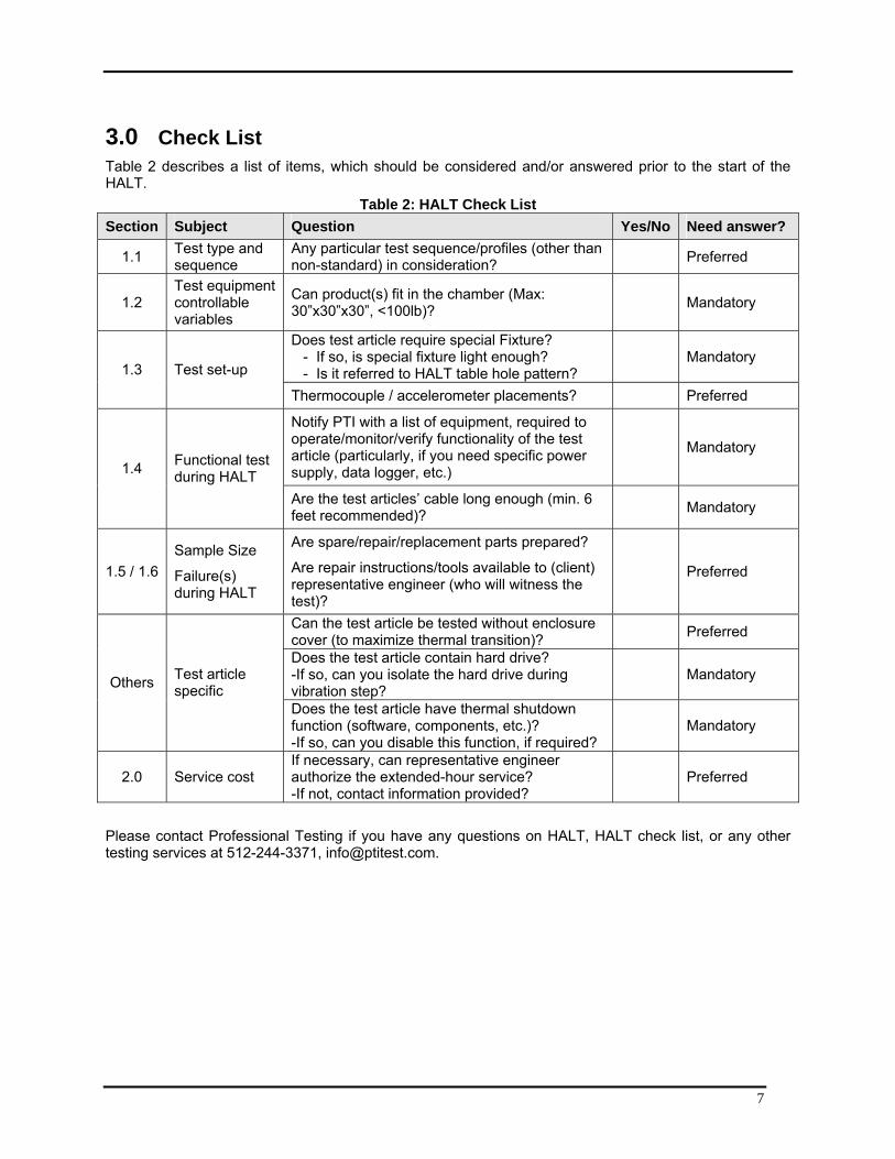
3.0 Check List Table 2 describes a list of items, which should be considered and/or answered prior to the start of the HALT.
Table 2: HALT Check List Section Subject Question Yes/No Need answer?
1.1 Test type and sequence
Any particular test sequence/profiles (other than non-standard) in consideration? Preferred
1.2 Test equipment controllable variables
Can product(s) fit in the chamber (Max: 30”x30”x30”, <100lb)? Mandatory
Does test article require special Fixture? - If so, is special fixture light enough? - Is it referred to HALT table hole pattern?
Mandatory 1.3 Test set-up
Thermocouple / accelerometer placements? Preferred
Notify PTI with a list of equipment, required to operate/monitor/verify functionality of the test article (particularly, if you need specific power supply, data logger, etc.)
Mandatory 1.4 Functional test
during HALT Are the test articles’ cable long enough (min. 6 feet recommended)? Mandatory
1.5 / 1.6 Sample Size
Failure(s) during HALT
Are spare/repair/replacement parts prepared?
Are repair instructions/tools available to (client) representative engineer (who will witness the test)?
Preferred
Can the test article be tested without enclosure cover (to maximize thermal transition)? Preferred
Does the test article contain hard drive? -If so, can you isolate the hard drive during vibration step?
Mandatory Others Test article specific
Does the test article have thermal shutdown function (software, components, etc.)? -If so, can you disable this function, if required?
Mandatory
2.0 Service cost If necessary, can representative engineer authorize the extended-hour service? -If not, contact information provided?
Preferred
Please contact Professional Testing if you have any questions on HALT, HALT check list, or any other testing services at 512-244-3371, [email protected].

8
4.0 Appendix 4.1 Detailed Description of Each Test Type 4.1.1 Thermal Step-Stress Test During temperature step-stress testing, the HALT system ducting will be positioned to allow for maximum airflow across the sample(s). Thermocouples will be attached to each of the test article(s) to measure the actual product temperature versus chamber set-point.
Cold Step Stress (CSS) Procedures: • Secure the test article on the HALT table and attach thermocouples in specified spots on the test
article. • Operate the test article and verify functionality of the product, prior to CSS test. • With the test article operating, begin HALT at 20C and dwell for specified duration1 (typically 15
minutes) • At the conclusion of dwell, perform a power cycling (if decided, can be applied multiple times) and
functionality/performance check • Decrease the temperature in pre-determined increment (typically 10C) and wait for a temperature
stabilization2. Upon temperature stabilization, complete the dwell for specified duration. • At the conclusion of dwell, perform a power cycling (if decided, can be applied multiple times) and
functionality/performance. • Continue this step-down until lower operating and destruct limits (failures) are observed (if
possible). • Modifications/repair to the observed failures can be made to the EUT, to continue stressing the
product till limits. Note 1: In general, dwell time would be counted after product has reached temperature stabilization.
Note 2: Temperature stabilization can be generally defined as the time when product reaches within +/-2C of the temperature set-point. However, due to complexity and mass of the product, some products may have unreasonably long temperature stabilization time. Therefore, it is an unavoidable practice to adjust the criterion for temperature stabilization to complete HALT within a reasonable amount of time. During temperature stabilization the product should get to at least 80% of the temperature set point. To maximize the thermal transition rate, the test can be performed with the enclosure cover removed (upon agreement).
Hot Step Stress (HSS) Procedures:
Similar procedure as CSS would be applied. Test starts at 30C and temperature will be increased in pre-determined increment until product fails. At each temperature, the test article will be kept for specified duration. Power cycling and/or functional testing will follow at the conclusion of dwell.
Any thermal shutdown function (software, components, etc.) within the product should be disabled during hot step-stress testing.
4.1.2 Rapid Thermal Transition Test Continuous hot and cold ramps will be applied to the product as fast as the chamber and the product will allow for a minimum of five cycles. The dwell time following temperature stabilization of the product will be 10 minutes minimum (total) at both cold and hot extremes. Temperature extremes will be based on the operating limits determined during the thermal step-stress. The functionality of the product should be verified throughout the test but especially during the transitions. A power cycle should be performed following each dwell. The functional testing will consist of the unit performing its normal operation.

9
4.1.3 Vibration Step-Stress Test The sample(s) under test will be secured to the vibration table with fixturing developed by Professional Testing (and/or the Client). Accelerometers will be placed on the sample(s) to measure vibration response of the product versus chamber set-point.
The step stress process will start at 5Grms and increase in 5Grms increments (in general) until operating and destruct limits are determined (if possible). If possible, modifications will be made to the sample as failures are encountered to increase these limits and ruggedize the product. The dwell time at each step will be approximately 10 minutes minimum to check the functionality of each sample under test. A one minute tickle vibration dwell at (5~10Grms) can be performed every 20Gs (i.e., at 20, 40, 60 and 80Grms). The functionality of the sample will be checked throughout the test and/or at least at the end of each dwell. The higher vibration level may have precipitated a failure which is only detectable under tickle vibration. A power cycle should be performed following each dwell. During each step the functional testing will consist of the unit performing its normal operation.
If the test article contains hard drive, it should be isolated during vibration test.
4.1.4 Combined Environment Test Ducting will be used to maximize airflow and to provide maximum thermal rates of change on each of the sample(s) under test. The test article(s) will be secured to the vibration table as they were during vibration step stress.
The sample(s) will be subjected to a combined environment of vibration and thermal stress with rapid temperature transition rates. A thermal profile will be developed with upper and lower temperature extremes close to the operational limits determined during temperature step stress. The profile will consist of five cycles similar to the Rapid Thermal Transition profile. Dwelling at each temperature extreme for a minimum of 15 minutes or longer to allow time for some temperature stabilization and to run any functional test routines, vibration will be applied to the test article(s) throughout the profile. The destruct limit (discovered during the Vibration Step Stress) will be divided by five (example: DL=40Grms then the vibration will start at 8Grms for cycle #1, next cycle will be 16Grms, 24, 32 and 40 for cycle 5). Stepping the vibration during thermal stress is important because the vibration response of many products changes as temperature changes. A power cycle should be performed following each dwell. During each run through the profile the functional testing will consist of the unit performing its normal operation.
4.2 Definitions: Operational / Destruct Limit The operating limit is defined as the point prior to which the sample stops operating but returns to operation when the stress level is decreased to that point. The destruct limit is the level at which the product stops functioning and remains inoperable even after the stress is relieved from the product. Figure 2 illustrates these two limits against product design limit.
Figure 2: Definitions: Operational / Destruct Limit