Ha469250
20
890 Quickstart Manual 890CA (Common Bus) Adaptor HA469250U000 Issue 3 (ISO A4) HA469250U001 Issue 3 (American Quarto) © Copyright 2009 Parker Hannifin Ltd. All rights strictly reserved. No part of this document may be stored in a retrieval system, or transmitted in any form or by any means to persons not employed by a Parker Hannifin Ltd., Automation Group, SSD Drives Europe, without written permission from Parker Hannifin Ltd . Although every effort has been taken to ensure the accuracy of this document it may be necessary, without notice, to make amendments or correct omissions. Parker Hannifin Ltd., Automation Group, SSD Drives Europe, cannot accept responsibility for damage, injury, or expenses resulting therefrom. WARRANTY Parker SSD Drives warrants the goods against defects in design, materials and workmanship for the period of 24 months from the date of manufacture, or 12 months from the date of delivery (whichever is the longer period) on the terms detailed in Parker SSD Drives Standard Conditions of Sale IA500504. Parker SSD Drives reserves the right to change the content and product specification without notice.
-
Upload
nguyen-truong -
Category
Education
-
view
83 -
download
0
Transcript of Ha469250

890 Quickstart
Manual
890CA (Common Bus) Adaptor
HA469250U000 Issue 3 (ISO A4) HA469250U001 Issue 3 (American Quarto)
© Copyright 2009 Parker Hannifin Ltd.
All rights strictly reserved. No part of this document may be stored in a retrieval system, or transmitted in any form or by any means to persons not employed by a Parker Hannifin Ltd., Automation Group, SSD Drives Europe, without written permission from Parker Hannifin Ltd . Although every effort has been taken to ensure the accuracy of this document it may be necessary, without notice, to make amendments or correct omissions. Parker Hannifin Ltd., Automation Group, SSD Drives Europe, cannot accept responsibility for damage, injury, or expenses resulting therefrom.
WARRANTY Parker SSD Drives warrants the goods against defects in design, materials and workmanship for the
period of 24 months from the date of manufacture, or 12 months from the date of delivery (whichever is the longer period) on the terms detailed in Parker SSD Drives Standard Conditions of Sale IA500504.
Parker SSD Drives reserves the right to change the content and product specification without notice.

Page 2
C o n t e n t s Page
Safety...................................................................................................................................................................... 3 Hazards to Personnel 3 Application Risk 3
• Risk Assessment 4 • Accessibility 4 • Protective Insulation 4 • RCDs 4
Introduction........................................................................................................................................................... 5 About this QuickStart 5
• SSD_Rail Busbar System 5 Installation............................................................................................................................................................. 6
Dimensions 6 • Ventilation 7 • Environmental Conditions 7
Overview................................................................................................................................................................ 8 890CA Power Connections................................................................................................................................ 9 SSD_Rail Connections...................................................................................................................................... 10
• Busbar Installation 10 Application Examples ....................................................................................................................................... 11
• Example 1: Enclosure/Row Changer (890CA////00) 11 • Example 2: Power Loss Ride-Through (890CA////RT) 12 • Example 3: Connection to Non-busbar Drives 13
Drive Start-up...................................................................................................................................................... 14 Before Applying Power : 14
Fuse Replacement............................................................................................................................................. 14 • Common Bus Adaptor : 890CA////00 14 • Common Bus Adaptor with Ride-Through : 890CA////RT 15
Appendix A: Product Code .............................................................................................................................. 16 Understanding the Model Number 16
Appendix B: Electrical Ratings ....................................................................................................................... 18 Appendix C: Reference Information............................................................................................................... 19

Page 3
Safety IMPORTANT Please read this information BEFORE installing the equipment.
Hazards to Personnel
WARNING This equipment can endanger life through rotating machinery and high voltages. Failure
to observe the following will constitute an ELECTRICAL SHOCK HAZARD. Metal parts may reach a temperature of 70 degrees Centrigrade in operation.
Before working on the equipment, ensure isolation of the mains supply from terminals L1, L2 and L3. The equipment contains high value capacitors which discharge slowly after removal of the mains supply. Wait for at least 3 minutes for the dc link terminals (DC+ and
DC-) to discharge to safe voltage levels (<50V). Measure the DC+ and DC- terminal voltage with a meter to confirm that the voltage is less than 50V.
Application Risk The specifications, processes and circuitry described herein are for guidance only and may need to be adapted to the user's specific application. Parker SSD Drives does not guarantee the suitability of the equipment described in the Manual for individual applications.

Page 4
Risk Assessment Under fault conditions, power loss or other operating conditions not intended, the equipment may not operate as specified. In particular: • The motor speed may not be controlled • The direction of rotation of the motor may not be controlled • The motor may be energised
Accessibility All live power terminals are IP20 rated only, since the equipment is intended to be installed within a normally-closed cubicle or enclosure, which itself requires a tool to open.
Protective Insulation • All control and signal terminals are SELV, i.e. protected by double insulation.
Ensure all wiring is rated for the highest system voltage. NOTE Thermal sensors contained within the motor must be single/basic insulated.
• All exposed metalwork in the Drive is protected by basic insulation and bonding to a safety earth.
RCDs Not recommended for use with this product. Where their use is mandatory, use only Type B RCDs (EN61009).
Caution This is a product of the restricted sales distribution class according to IEC 61800-3. It is designated as “professional equipment” as defined in EN61000-3-2. Permission of the supply authority shall be obtained before connection to the low voltage supply.
Page 5
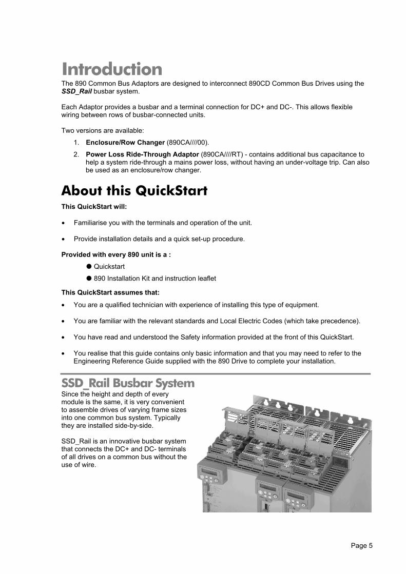
Introduction The 890 Common Bus Adaptors are designed to interconnect 890CD Common Bus Drives using the SSD_Rail busbar system. Each Adaptor provides a busbar and a terminal connection for DC+ and DC-. This allows flexible wiring between rows of busbar-connected units. Two versions are available:
1. Enclosure/Row Changer (890CA////00).
2. Power Loss Ride-Through Adaptor (890CA////RT) - contains additional bus capacitance to help a system ride-through a mains power loss, without having an under-voltage trip. Can also be used as an enclosure/row changer.
About this QuickStart This QuickStart will:
• Familiarise you with the terminals and operation of the unit.
• Provide installation details and a quick set-up procedure.
Provided with every 890 unit is a :
Quickstart
890 Installation Kit and instruction leaflet
This QuickStart assumes that:
• You are a qualified technician with experience of installing this type of equipment.
• You are familiar with the relevant standards and Local Electric Codes (which take precedence).
• You have read and understood the Safety information provided at the front of this QuickStart.
• You realise that this guide contains only basic information and that you may need to refer to the Engineering Reference Guide supplied with the 890 Drive to complete your installation.
SSD_Rail Busbar System Since the height and depth of every module is the same, it is very convenient to assemble drives of varying frame sizes into one common bus system. Typically they are installed side-by-side. SSD_Rail is an innovative busbar system that connects the DC+ and DC- terminals of all drives on a common bus without the use of wire.

Page 6
Installation Mount the 890CA unit(s) side-by-side with the 890CD units so that the SSD_Rail busbar system can be used. The 890CA is dimensionally the same as the Frame B 890CD unit.
Dimensions
413.
6
72.436.2
421.
657
57
12.5 25
258.5238.6
X
X
433.
6
260
Y
B
Dimensions are in millimeters (X : Power Bracket - 890 Installation Kit)
The units must be installed in an enclosure. Mount the drive using the keyholes and slots or on a 35mm DIN rail using the 890 Installation Kit supplied.
890 Installation Kit
The 890 Installation Kit is shown in the diagram attached to the bottom of the 890CA unit. The kit provides several options for earth/ground connections. It also includes the brackets for DIN rail mounting the unit. Refer to the instructions in the kit and use the appropriate parts. Permanent Earthing The unit must be permanently earthed according to EN 50178: For permanent earthing, one conductor, PE1, of >10mm² cross-section is required; or two individual incoming protective earth conductors, PE1 & PE2, of <10mm² cross-section. Each earth conductor must be suitable for the fault current according to EN 60204.

Page 7
Ventilation The 890CA and 890CD drives can be mounted side-by-side with no clearance necessary. A minimum of 150mm (6 inches) free-air space must be allowed at the top and bottom of each drive. If mounting drives above or below other equipment, the top and bottom distances should be added for overall clearance between drives. If connecting to a larger 690+ or 890 Frame E to K drive, also maintain the air clearance required by the larger drive. Refer to the relevant Product Manual supplied with that drive.
Environmental Conditions Operating ambient temperature 0°C to 45°C (32°F to 113°F) Enclosure rating IP20 – UL(cUL) Open type Atmosphere Dust free, non flammable, non-corrosive, <85% humidity,
non-condensing

Page 8
Overview
IMPORTANT: If only one LED is lit, an internal fuse has blown. Refer to page 14.

Page 9
890CA Power Connections • Connect DC power cables to DC+ and DC-
terminals.
The power MUST be connected DC+ to DC+, and DC- to DC-.
Maximum wire size: Frame B: 16mm2/4AWG (stranded with ferrule) 25mm2/4AWG (solid)
1 • Connect the earth/ground wire from the
Supply Protective Earth/Ground to the bottom ground bracket.
Maximum wire size: Frame B: 4mm2/12AWG
2
Connect a separate 24VDC power supply to power the internal fan. DO NOT use the 890CS or 890CD 24V outputs.
3

Page 10
SSD_Rail Connections WARNING
During commissioning, remove the fuses (or trip the circuit breaker) on your 3-phase supply. Make sure the power is OFF, and that it cannot be switched on accidentally whilst
you are working.
Caution All 890 units connected to the DC bus must be rated for the same 3∅ operating
voltage.
The following items are available from SSD Drives:
Busbar : Part No. BH465850 - 1m length, 10mm x 3mm copper
Busbar Insulator : Part No. BC465938U200 - 200mm length
The bus bar is rated at 140 Amps.
Busbar Installation 1. Simply select two correct lengths of the busbars and drop them in the slots shown in the close-up
top view. Secure with two screws (2.0 Nm), shown by the arrows. Fit insulating sleeve to any busbar that protrudes from the units.
2. For your safety and EMC compliance: ♦ Busbar: cut this to length so that both ends of the bar are fully inserted into a terminal –the
busbar must not protrude beyond the edge of the terminal clamp if the busbar is a terminating piece.
♦ Insulator: Fit this to all busbar external of the unit. It should butt-up to the sides of each unit. Press it firmly down onto the busbar for complete protection.
3. Close all Busbar Terminal Covers. They snap shut.

Page 11
Application Examples The 890CA unit provides a very flexible method of installing a common busbar system. It is important to note that the Busbar is rated at 140A, so when connecting to the 890CS Frame D, which is capable of more than 140A, use both SSD_Rail connections separately.
Example 1: Enclosure/Row Changer (890CA////00) The total loading on an 890CA unit (890CA////00) must not exceed 80A DC. Connecting several rows of 890CD units operating from a single 890CS, or connecting parts of a common bus system in different enclosure.
Example 1
Diagram showing connection options between the 890CS unit and the 890CA
unit using SSD_Rail Busbars and/or DC+ and DC- terminals.

Page 12
Example 2: Power Loss Ride-Through (890CA////RT) The total loading on an 890CA unit (890CA////RT) must not exceed 50A DC. A maximum of four 890CA////RT units may be used in a system. 890CA////RT units can also be used as "row-changers". The capacitors in the 890CA (890CA////RT) provide additional bus capacitance. This will increase the time before experiencing an under-voltage trip in the event of a mains power loss. To ensure an acceptable life-time for the capacitors in the unit, we recommend that the total loading on an 890CA (890CA////RT) does not exceed 50A DC.
Example 2
Diagram showing 890CA units with Ride-Through connected between the 890CS and 890CD units.

Page 13
Example 3: Connection to Non-busbar Drives The total loading on an 890CA unit (890CA////00) must not exceed 80A DC.
The total loading on an 890CA unit (890CA////RT) must not exceed 50A DC. Connecting 890CD units to an alternative DC source. For example, a 690+ drive that may be acting as a regenerative front-end.
Example 3
Diagram showing connection between the DC+ and DC- terminals of an alternative DC source and an 890CA unit.
* Note that the air clearance for the drive must be maintained.
Refer to the relevant product manual for details.
Page 14
Drive Start-up Before Applying Power : • Read the Safety section at the front of the QuickStart.
• Ensure that all local electric codes are met.
• Check for damage to equipment.
• Check for loose ends, clippings, filings, drilling swarf etc. lodged in the drive and system.
• Check all external wiring circuits of the system - power, control, motor and earth connections.
• Ensure that the fan in the 890CA unit is functioning.
• Ensure that the SSD_Rail has been correctly installed and securely fastened.
Fuse Replacement WARNING
During commissioning, remove the fuses (or trip the circuit breaker) on your 3-phase supply. Make sure the power is OFF, and that it cannot be switched on
accidentally whilst you are working. The equipment/system contains high value capacitors which discharge slowly after
removal of the mains supply. Wait for at least 3 minutes for the dc link terminals (DC+ and DC-) to discharge to safe voltage levels (<50V). Measure the DC+ and DC- terminal
voltage with a meter to confirm that the voltage is less than 50V.
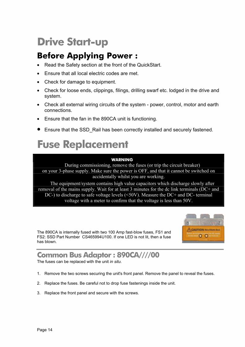
The 890CA is internally fused with two 100 Amp fast-blow fuses, FS1 and FS2: SSD Part Number CS465994U100. If one LED is not lit, then a fuse has blown.
Common Bus Adaptor : 890CA////00 The fuses can be replaced with the unit in situ.
1. Remove the two screws securing the unit's front panel. Remove the panel to reveal the fuses.
2. Replace the fuses. Be careful not to drop fuse fastenings inside the unit.
3. Replace the front panel and secure with the screws.
Page 15
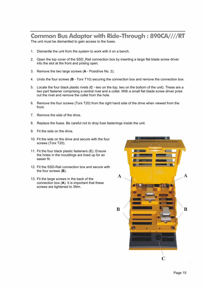
Common Bus Adaptor with Ride-Through : 890CA////RT The unit must be dismantled to gain access to the fuses.
1. Dismantle the unit from the system to work with it on a bench.
2. Open the top cover of the SSD_Rail connection box by inserting a large flat blade screw driver into the slot at the front and prising open.
3. Remove the two large screws (A - Posidrive No. 2).
4. Undo the four screws (B - Torx T10) securing the connection box and remove the connection box.
5. Locate the four black plastic rivets (C - two on the top, two on the bottom of the unit). These are a two part fastener comprising a central rivet and a collet. With a small flat blade screw driver prise out the rivet and remove the collet from the hole.
6. Remove the four screws (Torx T20) from the right hand side of the drive when viewed from the front.
7. Remove the side of the drive.
8. Replace the fuses. Be careful not to drop fuse fastenings inside the unit.
9. Fit the side on the drive.
10. Fit the side on the drive and secure with the four screws (Torx T20).
11. Fit the four black plastic fasteners (C). Ensure the holes in the mouldings are lined up for an easier fit.
12. Fit the SSD-Rail connection box and secure with the four screws (B).
13. Fit the large screws in the back of the connection box (A). It is important that these screws are tightened to 3Nm.

Page 16
Appendix A: Product Code Understanding the Model Number Each unit is identified using an alphanumeric code which records how the unit was configured when dispatched from the factory. Each block of the Model Number is identified as below using a 7 block short code (shaded) and a 9 block long code. The short code defines the "base build" product and the long code defines the configuration including options.
Example Model Number:
Block 1 890CA This is an 890CA Common Bus Adaptor
Block 2 5 Nominal input voltage rating is 500Vac
Block 3 0080B Current rating (continuous output RMS Amps) : 80 Amps DC Physical frame size B
Block 4 N Braking Control : No Braking Control
Block 5 00 Build Option : Not applicable
Block 6 N Performance Level : Not applicable
Block 7 US English documentation
Block 8 00 SSD standard livery
Block 9 00 Special options : none fitted
SHORT CODE
890CA/5/0080B/N/00/N/US/00/00

Page 17

Page 18
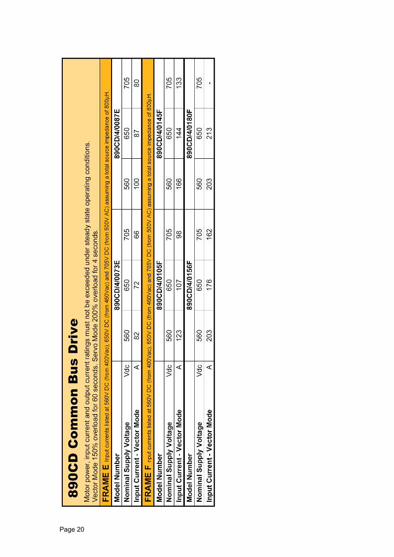
Appendix B: Electrical Ratings

Page 19
Appendix C: Reference Information
Page 20