GUIDELINES FOR ROAD DESIGN, CONSTRUCTION, … · 2017-10-03 · retaining of earth masses,...
45
GUIDELINES FOR ROAD DESIGN, CONSTRUCTION, MAINTENANCE AND SUPERVISION Volume I: DESIGNING Section 3: DESIGNING STRUCTURES DESIGN GUIDELINES (DG 1.3.1) Part 1: DEEP FOUNDATION ON BORED PILES AND ON WELLS
Transcript of GUIDELINES FOR ROAD DESIGN, CONSTRUCTION, … · 2017-10-03 · retaining of earth masses,...

GUIDELINES FOR ROAD DESIGN, CONSTRUCTION, MAINTENANCE AND
SUPERVISION
Volume I: DESIGNING
Section 3: DESIGNING STRUCTURES
DESIGN GUIDELINES (DG 1.3.1) Part 1: DEEP FOUNDATION ON BORED PILES AND ON
WELLS


Guidelines for Road Design, Construction, Maintenance and Supervision Deep foundation on bored piles
RS-FB&H/3CS – DDC 433/94 Volume 1 - Section 3 - Part 1 Strana 3 od 44
INTRODUCTION In difficult geological – morphological conditions where a load bearing ground, i.e. a rock geological base, is located at a depth greater than 6.0 m, it is appropriate to foresee deep foundation. In the up-to-date practice of bridge and civil engineering structure foundation bored piles, and wells are mostly used, as these types of foundations can reach a rock base at a depth of up to 40 m. Foundation on bored piles is one of the most frequent methods of the deep foundation. In particular the feasibility of being effectively incorporated into the bridge load bearing structures as well as a good adaptability to site conditions and geomorphologic ground properties are attributes, which open the door to this foundation method in numerous bridges and civil engineering structures. A rapid, reliable, and relatively inexpensive execution, made possible by means of the up-to-date mechanization, places the foundation on bored piles among those technologies, which are, in most cases, able to fulfil all the economical requirements of construction. Last but not least such a type of foundation attains high standards in protecting health of the construction manpower, as well as affects the environment insignificantly, for that reason it can be considered as ecologically adequate. The foundation on wells is such a foundation method where the vertical shaft is excavated in a similar way, as it is usual for wells in the narrower sense of the word. As the wells are essential members of the bridge load bearing structure, they influence the structural design, the construction costs and progress, the structural stability and durability, as well as the acceptability of the planned interventions in the space from the point of view of the ecology and the environment protection. The Design Guideline 1.3.1 provides fundamental lines for the design and execution of deep foundation on piles and wells in bridges and civil engineering structures. The contents of the Design Guideline are divided in several chapters: in the introductory part conditions of and bases for the use of deep foundation are indicated, followed by the chapters dealing with the design, where conceptions and constructive principles are discussed, then by a chapter presenting geostatic analysis, and, finally, by a chapter, discussing the deep foundation construction. The Design Guideline 1.3.1 is intended for design and construction of new structures, as well as for reconstruction of existing ones. It provides requirements and recommendations for designers and contractors, and shall be considered as a base for designing up-to-date civil engineering structures. The engineers are obliged, on the basis of Code of Engineers, and of the rules of their profession, to supplement these bases by technically and economically well considered, safe, as well as aesthetically conceived and executed structures.

Deep foundation on bored piles Guidelines for Road Design, Construction, Maintenance and Supervision
Strana 4 od 44 Volume 1 - Section 3 - Part 1 RS-FB&H/3CS – DDC 433/94
C O N T E N T S 1 SUBJECT OF DESIGN GUIDELINES..........................................................................................5 2 REFERENCE REGULATIONS.....................................................................................................5 3 EXPLANATION OF TERMS .........................................................................................................6 4 INTRODUCTORY CHAPTER.......................................................................................................7
4.1 Bases for deep foundation design.......................................................................................7 4.2 Circumstances in which foundation on bored piles is recommended.................................8 4.3 Circumstances under which foundation on wells is recommended ..................................10
5 DESIGN OF FOUNDATION ON BORED PILES........................................................................11 5.1 Selection of pile diameter, length, number, and arrangement ..........................................11 5.2 Design of bored pile steel reinforcement ..........................................................................14 5.3 Bored piles in water and soft soil ......................................................................................17 5.4 Design of connection of piles with bridge substructures...................................................19
6 DESIGN OF FOUNDATION ON WELLS....................................................................................21 6.1 General conception principles...........................................................................................21 6.2 Structural elements of excavation protection ....................................................................26 6.3 Foundation block and design of contact between well toe and foundation bottom ..........26 6.4 Methods of connecting a pier with a well ..........................................................................28 6.5 Anchoring a well in unstable ground .................................................................................30 6.6 Particularities of a well executed by lowering ...................................................................33
7 GEOSTATIC ANALYSIS OF BORED PILES .............................................................................35 7.1 Input data ..........................................................................................................................35 7.2 Bearing capacity of piles loaded with axial force ..............................................................35 7.3 Bearing capacity of piles loaded with horizontal force ......................................................37 7.4 Bearing capacity of piles arranged in a group...................................................................38
8 GEOSTATIC ANALYSIS OF WELLS .........................................................................................38 8.1 Design models...................................................................................................................39 8.2 Assessment of actions on wells ........................................................................................40 8.3 Load due to earth pressure ...............................................................................................40 8.4 Ultimate limit states and serviceability limit states ............................................................41
9 EXECUTION OF FOUNDATION ON BORED PILES.................................................................41 10 EXECUTION OF FOUNDATION ON WELLS ............................................................................42
10.1 Execution of wells by gradual unearthing .........................................................................42 10.2 Execution of wells by lowering ..........................................................................................44 10.3 Particularities of execution of wells in landslide active slope............................................45 10.4 Supervision, monitoring, and maintenance.......................................................................45

Guidelines for Road Design, Construction, Maintenance and Supervision Deep foundation on bored piles
RS-FB&H/3CS – DDC 433/94 Volume 1 - Section 3 - Part 1 Strana 5 od 44
1 SUBJECT OF DESIGN
GUIDELINES The present Design Guideline is intended for all the participants in planning, designing, constructing, and maintaining bridges and civil engineering structures. The goal of this Design Guideline is to present, discuss, and analyse common soil mechanical, constructive, technological, and organizational cognitions related to deep foundation of bridges. The selection of foundation method affects the investment process, conception, design, construction, and maintenance of bridges. The Design Guideline ensures a linkage of profound theoretical and professional knowledge as well as information from the literature with practical experiences in this field of activity as well as with technical regulations and standards. The Design Guideline is mainly intended for construction of new bridges; however, it is sufficiently common to be applicable to reconstruction of existing bridges and construction of civil engineering structures (supporting/retaining walls, galleries, cut-and-covers, tunnels). Bored piles are piles executed in-place by placing steel reinforcement and casting concrete into a previously bored or excavated circular hole in the foundation soil. The present Design Guideline deals with bored piles of diameters of 80 cm to 150 cm, executed vertically. The minimum pile length in the bearing layer of the foundation ground amounts to 6.0 m. The Design Guideline only deals with such bored piles, which are foreseen for foundation purposes, i.e. for the transfer of supporting forces from the structure into the foundation soil. Partially, such bored piles are discussed, where primary loads act in a direction perpendicular to the pile axis, and which are used for other purposes such as retaining of earth masses, protection of excavations, etc. (e.g. pile walls). A well is a bearing element, transferring supporting forces from the structure into the foundation soil through strata of lower, or nil bearing capacity. A well is constructed by gradual excavation of a vertical shaft including all the necessary protective measures.
Such wells are discusses, which are executed by gradual excavation in stages and by simultaneous protection, and wells carried out by gradual lowering of segments, which have been previously constructed above the ground. Usually, wells are of either circular or elliptical cross-section of a minimum diameter of up to D = 2.5 m. The maximum diameter depends of the pier conception, load magnitude, and foundation depth. Wells, constructed by gradual lowering of segments, are generally of a square or rectangular cross-section. In the up-to-date civil engineering, the foundation on caissons is no more used, thus it is not discussed in the present Design Guideline. 2 REFERENCE REGULATIONS Rulebook of technical norms for foundation of structures, Official Gazette of SFR Yugoslavia No.15-295/90; Rulebook of technical norms for concrete and reinforced concrete, Official Gazette of SFR Yugoslavia No. 11/1987, Official Gazette of Republic of Slovenia No. 52/200; - EN 1990:2002 Eurocode 0 Basis of design - prEN 1991 Eurocode 1 Actions on
structures - prEN 1992 Eurocode 2 Design of concrete
structures - prEN 1997 Eurocode 7 Geotechnical
design - prEN 1998 Eurocode 8 Design of
structures for earthquake resistance EN 1537:1999 Execution of special geotechnical work – Ground anchors EN 1536:2002 Execution of special geotechnical work – Bored piles DIN 4014 Bored piles - execution, dimensioning, bearing capacity SIA 192 Pile foundation EN 206-1:2003 Concrete – Part 1 – Specification, properties, production, and conformity

Deep foundation on bored piles Guidelines for Road Design, Construction, Maintenance and Supervision
Strana 6 od 44 Volume 1 - Section 3 - Part 1 RS-FB&H/3CS – DDC 433/94
3 EXPLANATION OF TERMS Deep foundation signifies foundation on bored piles and foundation on wells at depths greater than 6.0 m. Shallow foundation means foundation on blocks, slabs or strip foundations; it is used, where strata of sufficient bearing capacity and low deformability are located at relatively small depths (up to 6.0 m). Pile is a bearing element, which function is to transfer supporting forces from the structure into the bearing soil through strata of lower, or nil bearing capacity. Bored pile is an element, executed in-place by placing steel reinforcement and casting concrete into a previously bored or excavated circular hole in the foundation soil. Pile cap is the upper part of a pile, usually connected with substructure members; it takes the load from the substructure. Pile foot is the lower base of the cylindrical body of a pile, transferring the load into the foundation soil by activating normal contact stresses. Pile cylinder circumference is the cylindrical body of a pile transferring the load by activating shear contact stresses. Upright pile is a pile, which transfers all the supporting force or a major part of it into the foundation soil by activating compressive stresses below the pile foot. Friction pile is a pile, transferring a majority of the supporting force into the ground by activating shear stresses at the pile cylinder. Compression pile is a pile, which takes compressive forces, i.e. the compressive axial force. Tension pile is a pile, which takes tensile forces. Pile bearing capacity is a physical quantity expressed with symbols of engineering mechanics for axial force (N), bending moment (M), and shearing force (V); it represents a limiting value at which safety is still ensured in compliance with the criteria of failure and serviceability.
Pile axial bearing capacity is a pile bearing capacity limited to the consideration of the axial force ensured by the internal bearing capacity of the pile (i.e. of materials within a pile), and by the external bearing capacity of the foundation soil, achieved by the bearing capacity of the soil below the pile foot, as well as of the soil at the pile cylinder. Pile bending bearing capacity is a pile bearing capacity limited to the consideration of the bending moment ensured by the internal bearing capacity of the pile (i.e. of materials within a pile), and by the external bearing capacity of the foundation soil, achieved by the lateral resistance of the soil at the pile cylinder. Protective pipe is usually a steel pipe serving as a supporting shuttering in the excavated hole for a pile, preventing crumbling of the wall into the excavated hole. Flushing liquid is dispersion in a liquid aggregate state, usually a mixture of colloidal clayey grains and water (or only water), acting by its hydrostatic pressure on the excavation hole wall thus having a function of a retaining medium, which prevents crumbling of the wall into the excavated hole. Pile beam is a load bearing beam element of the substructure, usually of reinforced concrete, interconnecting pile caps into planar bearing units; by means of a pile beam, supporting forces are transferred into several piles at the same time. Pile block is a reinforced concrete load bearing element of the substructure, connecting pile caps in spatial bearing units; by means of a pile block, supporting forces are transferred and distributed into several piles. Well is a load bearing element transferring supporting forces from the structure into the bearing foundation soil. It is carried out by excavating through non-bearing strata of the foundation soil, or strata of a low bearing capacity. Filled well is a well, which vertical shaft is filled up with partially reinforced filling concrete, or with gravel. A pier is fixed to the well at the top of the latter. Hollow well is a well, where the space between the pier and the well cylinder is not filled up. The pier is fixed to the well at the well foundation toe.

Guidelines for Road Design, Construction, Maintenance and Supervision Deep foundation on bored piles
RS-FB&H/3CS – DDC 433/94 Volume 1 - Section 3 - Part 1 Strana 7 od 44
Excavation protection is all the protective measures, performed during excavation works for a well. Ring is a reinforced concrete wall element, which takes earth pressures during excavating vertical shaft for a well. Shot cement concrete is a mix of aggregate, cement, water, and admixtures, applied by spraying into or onto a structure. It can either form a structural concrete or it is only a façade cover. Well cylinder circumference is the cylindrical body of a well, transferring forces into the foundation soil by activating shear contact stresses. Well cylinder wall is a reinforced concrete wall of a hollow well, or of a well filled up with gravel. Well toe is the lower part of a well, transferring loads into the foundation soil by activating normal contact stresses. Foundation body is the soil below the ground level, composed of strata of different properties, decisive to determine the foundation soil bearing capacity. Drainage signifies evacuation of water from behind a supporting/retaining wall. Working field is an area, or a cut into slope to execute a well. 4 INTRODUCTORY CHAPTER 4.1 Bases for deep foundation design Bored piles and wells are constituent parts of a bridge or a civil engineering structure, where the following bases for design apply: surveying, road-traffic, spatial-town planning, hydrological-hydrotechnical, meteorological-climatic, seismic, and geological-soil mechanical data in the influence area of a structure. Input design data shall be acquired, documented, and interpreted by taking account of current regulations and DG 1.2.1 General Guidelines for Designing Road Bridges. A fundamental document indicating geotechnical data for designing deep foundations is a geological – soil mechanical report on soil composition and foundation conditions. The extent of such report
depends on the level of the bridge foundation design. Generally, it shall comprise the following geotechnical information: • a geographic-geomorphologic description
of the road alignment area; • geological and soil mechanical conditions
in the road alignment area; • a description of field and laboratory
investigations; • an information on seismic conditions in the
investigated area; • a definition of geotechnical conditions of
bridge foundation and construction; • a master layout of the motorway alignment
in the bridge area; • a geological – soil mechanical chart of the
bridge area, with boreholes indicated; • a hydro-geological chart of the bridge area; • a geological – soil mechanical chart of the
bridge area; • a longitudinal geological - geotechnical
profile; • transverse geotechnical profiles at location
of individual piers and abutments, with strata of individual rock types, locations of shallow and deep landslips, and ground water levels indicated.
Geological boreholes shall be carried out at each pier/abutment location, and shall extend by at least 7.0 m below the foreseen bottom of a pile or a well. By the geotechnical foundation conditions the following information shall be provided: • division of rock in deformational strata with
individual characteristics indicated: volume weight γ, shear angle φ, cohesion c, modulus of elasticity and deformability, and Poisson’s ratio (for a finite element analysis), as well as modulus of compression Mv, and both vertical and horizontal coefficients of ground reaction: Kv, Kn;
• allowable bearing pressure and settlements of the foundation soil;
• stability analyses including calculations of earth pressures to the well circumference (active, passive, at rest, at landslip);
• general stability of the slope for pier deep foundation.
The types of data, that structural designers may require, depend on the design model and interaction foundation – foundation soil respectively.
Deep foundation on bored piles Guidelines for Road Design, Construction, Maintenance and Supervision
Strana 8 od 44 Volume 1 - Section 3 - Part 1 RS-FB&H/3CS – DDC 433/94
4.2 Circumstances in which foundation on
bored piles is recommended 4.2.1 Introduction Nowadays, piles of large diameters are used to the greatest possible extent. Therefore, this Design Guideline deals with the design and construction of such piles. Pile foundation belongs to widespread deep foundation types. It is particularly introduced in cases where shallow foundation is not feasible due to foundation soils of low bearing capacities, or where structures founded on shallow foundations would experience excessive settlements, inclinations, or even sinking into the ground. Considering all the advantages, the use of piles is in full swing. This particularly applies in cases where significant concentrated forces need to be transferred into the load bearing soil by means of bored piles of large diameters. Such a solution is technical justified and economical; the loads can also be taken by several smaller piles, taking account of both magnitude and direction of supporting forces. Pile foundation is feasible in a soil of low bearing capacity, a solid soil, ground water, and surface waters. Such a foundation is economical, safe, and acceptable from the ecological point of view. The up-to-date construction mechanization enables a quick, effective, and economical pile execution. However, suitable access roads and working fields are required. 4.2.2 Geological – soil mechanical
conditions suitable for pile foundation
Basically, a pile foundation shall be foreseen in case of a soft soil in the upper part of the foundation ground at depths greater than 6 m, from the level where supporting forces from the structure are taken, up to the level of a load bearing stratum suitable to foundation. Supporting forces are transferred to a greater depth via supporting elements, i.e. piles. As a rule, a pile foundation is a correct decision in cases where the soil bearing capacity at the foundation level is sufficient to take supporting forces, but it does not ensure a safe foundation due to insufficient stability. Such circumstances usually occur on slopes.
Areas that seem to be favourable to a shallow foundation, might be unsafe for other influences such as river erosion, possible subsequent changes in the ground profile, etc. A pile foundation is frequently required due to the ground water level and regime resulting from the pit excavation (excessive inflow of water into the construction pit, problem of hydraulic fracture of the foundation soil, impacts on adjacent structures, etc.). Piles are also designed in cases where a construction pit might represent a risk of losing equilibrium of soil strata at the pit, or complex measures to protect the construction pit would be necessary. 4.2.3 Static conception of the structure as
a condition to foresee a pile foundation
Foundation on bored piles is especially suitable to structures, which conceptions are sensitive to major settlements of piers. Particularly such structures are in question, which are located next below the road carriageway, where settlements can cause a risky deformation of the carriageway. In statically indeterminate continuous and frame structures, differential settlements can become the most important load case. To such structures, foundation on piles is particularly suitable, as a direct transfer of supporting forces into strata of high bearing capacity is generally ensured, which means that the settlements are relatively small as well, and they are not related to consolidation processes of the foundation soil below foundations, as well as to the settlements of connecting fills. Tending to conceive structures without any expansion joints and bearings (integral structures), or to reduce those elements to a minimum possible extent, static conceptions foreseeing piles are generally favourable, as base parts of piers and abutments are more flexible, thus allowing greater displacements at relatively insignificant internal forces and moments.

Guidelines for Road Design, Construction, Maintenance and Supervision Deep foundation on bored piles
RS-FB&H/3CS – DDC 433/94 Volume 1 - Section 3 - Part 1 Strana 9 od 44
4.2.4 Location of the structure as a
condition to foresee a pile foundation
As a rule, pile foundation is much less dependent on all the conditions at the construction location and in the ground below the structure, as construction impacts are practicably negligible in comparison with shallow foundation. A pile foundation does not represent any major problem, when a structure is to be founded in water (river, sea), as the construction carried out from a platform on pontoons are proven. The technology of an underwater extending of piles to piers is absolutely realizable to all well qualified contractors. In riverbeds where changes in the bed, particularly deepening of the bottom, due to erosion are quite probable, a pile foundation is a reliable solution. When construction works are carried through in confined conditions (in towns, narrow gorges), where impacts on adjoining structures and plots of land shall be reduced to minimum, the foundation on piles is the most appropriate solution. Foundation on bored piles is not an adequate solution on steep, and often unstable slopes, where construction of access roads and working fields is problematic and may provoke an unstable behaviour of the slopes. 4.2.5 Conditions under which bored piles
are feasible Structural conception shall take account of the conditions under which piles are feasible, as well as of warnings by the performer of the foundation soil investigations: - execution of piles in cohesive soil of low
plasticity, where vibrations during construction may bring the soil to a condition of a viscous consistency;
- possible obstacles during boring (hidden existing structures, foundations, etc.);
- excavation in soft cohesive soil, which is pasting on the protective pipe; during casting, the concrete can escape laterally due to insufficient supporting effect of the surrounding soil on the fresh concrete;
- execution in gravel consisting of predominantly large grains, where, due to a significant permeability, retaining of fresh concrete in the excavated profile is
questionable, and the fresh concrete tends to flow through gravel grains;
- encountering large stones or rocks in cohesive or non-cohesive soil; when hit by a chopper, such stones or rocks behave as spring-elements, thus the chopper is ineffective;
- excavation in stratified rocks, where a chopper is ineffective;
- inclined strata where the protective pipe tends to incline;
- in fill slopes and different thicknesses of strata at the pile, the protective pipe tends to incline;
- execution in strata containing ground water under hydrostatic pressure (artesian water) is particularly hazardous; there is a possibility of soil fracture within the protective pipe, and a risky execution of an artesian well in the pile borehole, including all the consequences resulting from the water outflow from the artesian stratum;
- execution in aggressive ground or a ground containing aggressive water where harmful actions on the completed pile shall be taken into consideration;
- other possible particularities of the soil. The feasibility of piles shall also be verified due to a particularity of the construction location. The following restrictions occur frequently: - accessibility for boring devices (machine
dimensions), and required size of the working field;
- insufficient available (confined) working space to execute the piles;
- insufficient clear height to execute the piles (e.g. below high-tension transmission lines);
- height position of the working field, which might limit possible construction alternatives;
- load bearing capacity of the working field to allow machines to enter the site (e.g. ground of very low bearing capacity);
- public utilities in the ground and in the air, particularly gas mains and high-tension transmission lines);
- required safety distances; - noise restrictions due to vicinity of
population; - working time restrictions due to prohibited
noise emissions in settlements. From the conditions/restrictions mentioned above it is evident, that the number of input parameters is quite large, and that those parameters are specific for each location, therefore the design shall be carried out very deliberately and carefully.

Deep foundation on bored piles Guidelines for Road Design, Construction, Maintenance and Supervision
Strana 10 od 44 Volume 1 - Section 3 - Part 1 RS-FB&H/3CS – DDC 433/94
4.2.6 Construction technology as a
condition for pile foundation Pile foundation can be carried out quite quickly and it generally does not cause any unexpected situations, which could extend the construction time (soil crumbling into construction pits, unforeseen braking in of ground water or surface water). As a rule, pile foundation is independent on climatic conditions such as low or high temperatures, long lasting rainfall causing soaked ground, increased water levels, etc., on condition that suitable measures have been taken in due time. A structure founded on piles needs not be buried deeply, as it can be practically founded on the ground surface, thus the quantities of excavated and placed material are reduced, and the costs related to construction work are diminished. In deep foundation of viaducts and bridges of large spans, where significant supporting forces are transferred into the foundations consisting of a large number of piles, bored piles are often not the most adequate solution, as they require construction of pile blocks of extremely great dimensions, including all the accompanying problems. It is advantageous to construct abutments on high fills, where piles are bored through a completed fill, thus a time-consuming fill compaction between supporting columns does not take place; at a correct execution, abutment settlement is independent on the fill settlement. The probability of polluting the ground water is essentially smaller in case of pile construction in comparison with a construction in open pits, however on condition that the machinery employed for the pile execution is maintained appropriately. Specialized companies for execution of geotechnical works and other civil engineering enterprises have sufficient number of up-to-date boring sets on their disposal. As such mechanization is not applicable to other construction works, it shall be used as expediently as possible.
4.3 Circumstances under which
foundation on wells is recommended Foundation on wells as a type of deep foundation is recommended particularly in the following cases: • in founding bridge piers on a slope, i.e. in
slope viaducts running along a slope, or in viaducts crossing valleys, where this is required by the geological composition of soil, slope inclination, and where the access for heavy mechanization (boring sets for pile execution) is rendered difficult or even impossible;
• in founding bridges consisting of long spans, where a large number of piles for each individual pier or abutment would require uneconomically large dimensions of pile blocks;
• in cases, where a well foundation is more favourable in view of the construction costs;
• the transfer of forces from the pier to the foundation soil is more direct in well foundation than in foundation on bored piles.
A deep foundation on wells is selected particularly in the following cases: • to preserve the slope natural stability
(loosened and soaked ground); • to ensure stability of foundations and
piers/abutments also in cases where a weathered ground part becomes unstable in the bridge area;
• at transferring significant load into the foundation soil at greater depth, where the upper strata are of a low bearing capacity, or where the conditions for a shallow foundation are not fulfilled due to the unstable ground; the deformations shall be as small as possible;
• when the ground at the excavation stage lose their strength or become unstable in a short time;
• where a greater height of piers is required and their stiffness should be reduced respectively (hollow wells shall be introduced);
• where an execution of access roads and working fields for the mechanization would give rise to additional slope instabilities.
Advantages of well foundation are the following: • a direct load transfer from a pier into the
foundation soil is ensured; • the foundation soil is visible and kept under
control at the entire excavation depth;
Guidelines for Road Design, Construction, Maintenance and Supervision Deep foundation on bored piles
RS-FB&H/3CS – DDC 433/94 Volume 1 - Section 3 - Part 1 Strana 11 od 44
• the actual correct depth of the foundation
soil can be determined during excavation works in view of the actual ground properties;
• a well is such a protection of the construction pit, which does not provoke any ground movements;
• the intervention in the environment is minimum.
Well foundation is suitable in a relatively cohesive soil, and in cases where the ground water level is lower than the foundation level. However, the shaft circumference can also be protected in non-cohesive soil (grouted apron, shot cement concrete). Where the ground permeability is relatively low, the ground water level can be lowered below the foundation level by pumping the water. In landslide areas, in addition to morphological and geological conditions, the following requirements shall be fulfilled when a well foundation is foreseen: • the well circumference shall primarily
protect a pier from the earth pressure action;
• when executing a well circumference it is necessary to ensure surface water drainage to prevent an additional destabilization of a slope prone to land-sliding;
• the well circumference shall ensure protection at well excavation at both construction and service stage of a structure;
• the well circumference shall transfer the earth pressure load, and the pressure due to slope movements of reasonable probability, into the foundation soil without any damage.
Both technical and economical restrictions of use apply to the wells. These aspects are fully interconnected. From the technical point of view those restrictions apply, when the ground becomes unstable in a short time and at a small excavation depth. This particularly applies to fine sand and silt exposed to water, which might break in, and to weathered rock below the ground water level, or in the presence of the pore water. Where piers are founded in water (e.g. rivers, lakes, etc.), such wells shall be introduced, which are carried out by segments on provisionally made peninsulas or islands, lowered gradually by a simultaneous undermining. A suitable foundation depth in the water amounts to 6-8 m, depending on the working level of the water.
On a dry and flat ground a well foundation is reasonable at a depth greater than 6.0 m; on the contrary, the foundation shall be carried through as a shallow one with a spread excavation. 5 DESIGN OF FOUNDATION ON
BORED PILES 5.1 Selection of pile diameter, length,
number, and arrangement 5.1.1 General Piles shall be selected taken account of the parameters indicated in 4.2 above. - Pile diameter shall be determined
particularly on the basis of the required load bearing capacity (axial, bending) and feasibility of a pile, as well as available technology.
- For smaller bridges and therefore minor actions piles of smaller diameters (∅ 80 and ∅ 100 cm), whereas for larger bridges and major actions piles of larger diameters (∅ 125 and ∅ 150 cm) are selected.
- The pile length, particularly the toe depth, generally depends on geotechnical conditions, whilst the pile cap is determined on the basis of the selected conception, taking account of the structural geometry and ground profile, as well as other specificities at the construction site.
- The pile arrangement shall be adjusted to the conception of piers/abutments. The goal shall be to foresee a smaller number of piles of larger diameters, where the unfavourable interaction of the piles is less important, whilst the model of taking the loads is clearer, as the flow of forces can be followed easier.
- If feasible, piles shall be so arranged as to avoid construction of large pile beams and blocks of significant loading and great amount of reinforcing steel.
5.1.2 Selection of pile diameter First, the pile diameter is determined on the basis of the external bearing capacity calculation to be performed by one of the design methods taking account of: - results of static load testing, - results of empirical or analytical calculation
methods, - results of dynamical testing - observations of behaviour of comparable
pile foundation.

Deep foundation on bored piles Guidelines for Road Design, Construction, Maintenance and Supervision
Strana 12 od 44 Volume 1 - Section 3 - Part 1 RS-FB&H/3CS – DDC 433/94
Irrespective of the method adopted, the results shall comply with relevant experiences in similar foundations. When the pile bearing capacity, on the basis of which both structure and its foundation are conceived, is determined approximately, informative values can be introduced, being indicated for common soil and rock types in different literature. In chapter 7 informative characteristics in compliance with the DIN V 1054-100, and simplified equations to determine the pile bearing capacity are indicated. After the pile external load bearing capacity is calculated, the internal one shall be verified as well. Design methods for a circular cross-section with or without steel reinforcement shall be applied. As a rule, the deflection needs not be taken into consideration, with exception of long piles located in foundation soil consisting of very soft or viscous strata along the pile, or of piles extended by piers in water or air. Forces resulting from water streaming or from vessel or ice impacts on the piers increase the initial geometrical imperfections, and consequently the hazard of pile deflection in connection with the pier. The pile diameter selection is also influenced by the execution method (protective pipe or flushing liquid), and by the piling depth. The ratio of the diameter to the length of a bored pile is indicated in table 1: Table 1: Pile length in dependence on the execution method
Pile in a borehole with protective pipe diameter ∅ 0.8 m ∅ 1.2 m ∅ 1.5 m
length max 20 m up to 25 m 35 m
Pile in a borehole with flushing liquid diameter ∅ 0.8 m ∅ 1.2 m ∅ 1.5 m
length max 20 m up to 30 m 40 m Piles of larger diameters are generally more economical, as the load bearing capacity is increasing approximately by the square of the diameter; in addition, geometrical perfection and more favourable conditions for casting concrete, and therefore more reliable protective cover to the reinforcement can be ensured easier; the hazard of a the pile discontinuity is diminished, etc.
5.1.3 Selection of pile length The pile length depends particularly on the geotechnical conditions of the foundation soil, or the depth of the soil stratum suitable to foundation, and the depth of the rock respectively. It is reasonable to consider a depth proposed by the soil mechanics specialist on the basis of geotechnical investigations. To specify the definitive length (depth) of a pile, data on the soil composition acquired during pile excavation works, are often used. As circumstances require, the length of the fist piles as well of the next ones can be increased. Hazards indicated in the passage below shall be taken into account. Definition of pile length (depth) requires special attention in view of thickness of the stratum where the pile foot will be located, as punching may occur in case of an insufficient stratum thickness. For the selection of greater pile lengths, the foreseen construction method is also important, as some restrictions due to friction at pressing-in the protective pipe, and difficulties at placing longer and heavier reinforcement cages may arise. By means of the up-to-date equipment, bored piles can be reliably executed up to a depth of 35 m. 5.1.4 Arrangement of bored piles Two basic arrangements of piles below a bridge pier or abutment are possible: - arrangement of individual piles below the
substructure where geotechnical conditions and pile spacing ensure, that each pile is functioning individually,
- arrangement of piles below the substructure, taking account of geotechnical conditions, in such a number and at such a spacing, that one can consider them as a group of piles.
In practice bridge piers/abutments are founded on several piles. For smaller bridges, piers can be founded on a single pile of larger diameter (∅ 150 cm), which is continued in the pier. The effect of adjoining piles need not be taken into account, i.e. the load bearing capacity needs not be reduced, when the axial spacing amounts to at least 3 times pile diameter. Of course, this is only a rough estimation, as geotechnical conditions as well as conditions of transferring the load

Guidelines for Road Design, Construction, Maintenance and Supervision Deep foundation on bored piles from the pile into the foundation soil (normal force below the pile foot / friction force at pile circumference) have an essential influence on the bearing capacity. On the basis of analysis of the mechanism of transferring forces from piles into the foundation soil, at simultaneous consideration of geotechnical conditions, it is possible to analyse the pile interactions quite accurately.
It is particularly important to take account of interaction of long friction piles, whilst interactions of piles standing on a hard rock base are essentially reduced. The procedure of determining bearing capacity of a group of piles to take both vertical and horizontal forces is indicated in chapter 7. Pile arrangement is important not only to the load bearing capacity, but also to the transfer of supporting forces from the structure into the piles. If possible, piles shall be so arranged as to ensure an optimum model of transferring forces into the foundation soil, and enable an economical design of substructure members.
The Rulebook of technical norms for foundation of structures specifies the minimum admissible pile spacing (refer to table 2); the absolute minimum pile spacing is determined by the construction feasibility and the foundation soil properties.
Some fundamental conceptions of the system piles – foundation beam are indicated below, taking account of the pile arrangement resulting from the direction of supporting forces from the structure, and the pile bearing capacity (Fig. 5.1).
Table 2: Minimum pile spacing Piles transferring the load into the foundation soil mainly via pile foot
2.5 d
Piles in non-cohesive soil of higher density, transferring the load into the foundation soil mainly by friction
3 d
Piles in non-cohesive soil of low density, and in cohesive soil, transferring the load into the foundation ground mainly by friction
5 d
In major bridges where supporting forces are significant, piers/abutments are founded on groups of piles with large and massive pile blocks, or on wells.
Fig. 5.1: Possible arrangements of bored piles below bridge piers
RS-FB&H/3CS – DDC 433/94 Volume 1 - Section 3 - Part 1 Strana 13 od 44

Deep foundation on bored piles Guidelines for Road Design, Construction, Maintenance and Supervision 5.2 Design of bored pile steel
reinforcement 5.2.1 General instructions The steel reinforcement amount along a pile is determined on the basis of calculated internal forces and moments in a pile. The following shall be considered when designing pile reinforcement: - amount of longitudinal (main) and stirrup
reinforcement assessed by calculation, - technical regulations dealing with
reinforced concrete structures, - reinforcement design principles, which
apply to circular cross-section, - physical-technological characteristics of
reinforcing steel, and - specific requirements resulting from
construction technology. The first three of the above provisions can be fulfilled by an usual knowledge of structural analysis and dimensioning, which apply to circular cross-sections under compression or tension, and of low axial force eccentricity. In piles, bending and shear is specific and often relatively significant, which also applies to exposition conditions. Physical-technological properties of reinforcing steel to be used in pile construction are essential, as anchor and overlapping lengths shall be determined correctly, and the reinforcement shall be suitable to bending and welding. The reinforcing steel producer is obliged to submit adequate certificates indicating all the properties required. By far the most specific requirements in the pile reinforcement design result from the conditions in which the reinforcement is placed, from the pile construction, geotechnical conditions, hydrology, and a series of other specific requirements; if these conditions are not taken into account, a poor performance or even unfeasibility may result. In view of that fact, cooperation between the designer and the qualified piling contractor or authorized method engineer is indispensable. The pile reinforcement can be placed either in a single piece for the entire pile length, or by extending the reinforcement cage during construction. Self-supporting reinforcement cages shall be sufficiently solid and stiff to prevent their deformation due to the dead weight during transportation, lifting, and placing into the pile shaft. Further loads are kinematical forces of liquid concrete at pile
casting by means of a funnel (contractor). Reinforcement cages are also supporting structures for steel shuttering pipes, when piles are cast in water. Taking account of all the indicated construction conditions two fundamental types of reinforcement cages are possible: - tied reinforcement cages on welded
supporting framework, and - welded self-supporting cages. 5.2.2 Tied reinforcement cages Tied reinforcement cages consist of supporting framework made of welded steel of sufficient impact strength (toughness), to which the load bearing reinforcement is tied by means of annealed wire. The framework is composed of longitudinal bearing bars and bearing rings, of a frame at the bottom, and of suspension elements on the top of the cage. Longitudinal bearing bars of the framework can be welded with bearing rings inside or outside the ring. The framework can be built of non-certified structural steel, reinforcing steel, and by non-attested welding. Longitudinal bars of the bearing framework (Fig. 5.2) are usually of the same diameter as the longitudinal rebars – refer to table 6. When bars of a larger diameter are required to ensure the necessary bearing capacity of the cage, they shall be welded on the internal side of the rings. Therefore, longitudinal bars shall be of steel that is capable of being welded. Framework rings are usually made of structural flat or round steel, or reinforcing steel, which shall be suitable to welding. It is essential to take account of technological requirements, in particular of the ring external diameter, as the ring determines the external diameter of the entire cage and, therefore, the adequateness of the latter to installation (Fig. 5.2).
Fig. 5.2: Structure of pile reinforcement cage
Strana 14 od 44 Volume 1 - Section 3 - Part 1 RS-FB&H/3CS – DDC 433/94

Guidelines for Road Design, Construction, Maintenance and Supervision Deep foundation on bored piles In table 3 spacing of rings made of flat or round steel is indicated in dependence on the longitudinal bar diameter. In case that the rings made of round steel or reinforcing steel are doubled at spacing of 10 – 20 cm, axial spacing for rings made of flat steel apply. Table 3: Spacing of load bearing rings
Diameter of framework longitudinal
bars
Rings made of flat steel
Rings made of
round steel
∅ ≤ 20 mm 2,5 m 1,75 m ∅ > 20 mm 3,0 m 2,0 m
RS-FB&H/3CS – DDC 433/94 Volume 1 - Section 3 - Part 1 Strana 15 od 44
In table 4 recommendable dimensions of flat steel are indicated in dependence on the pile diameter. Table 4: Cross-section of flat steel of load bearing rings
Pile diameter Cross-section of flat steel of a ring
∅ 80 cm 60 x 8 mm ∅ 120 cm 80 x 8 mm ∅ 150 cm 100 x 10 mm
Upon placing the cage into the pile borehole and casting the concrete into the pile body, the cage receives significant loads. Therefore, the stiffness of rings is often insufficient for piles of larger diameter, thus reinforcement shall be inserted to ensure additional safety from deforming. Commonly, crosses of reinforcing steel are built-in, which, in case of piles of larger diameters, do not represent any essential obstacle to concrete casting pipe (Fig. 5.3). In case of heavy cages, diagonal bars should be installed to prevent transversal deformation of the cage.
Fig. 5.3: Cross bracing
Spacers are extremely important elements of the reinforcement cage, ensuring necessary distance between the cage and the borehole protective pipe, as well as the final distance between the cage and the borehole wall, which guarantees the required thickness of protective concrete cover to the reinforcement. In table 5, minimum thicknesses of concrete cover in dependence on the pile construction technology are indicated. Table 5: Minimum thickness of protective concrete cover to the reinforcement
Construction technology
Concrete cover
thickness For piles of ∅ ≥ 80 cm executed in borehole protected with pipe
c = 6 cm
For piles executed in borehole without protective pipe For piles made of underwater concrete and concrete of maximum grain size up to 32 mm For piles where major unevenness in the borehole wall exist
c = 7.5 cm
Where piles are carried out using borehole protective pipes, spacers made of reinforcing steel welded onto the bearing framework of the cage, or spacers made of fibre concrete are used. Where no protective pipes are introduced, it is more recommendable to foresee spacers made of flat steel to achieve a more reliable fix contact between the spacers and the borehole wall. In Fig. 5.4, proven methods of spacer execution are presented.
Fig. 5.4: Methods of executing spacers Cage foot shall be carried out is such a way that the concrete casting pipe can reach the bottom of the pile borehole, that lifting of the cage upon pulling out the borehole protective pipe and/or concrete casting pipe is prevented, and that plunging of the cage into the borehole bottom is rendered impossible.

Deep foundation on bored piles Guidelines for Road Design, Construction, Maintenance and Supervision Bent longitudinal bars or welded-on cross spacers in combination with load bearing rings welded entirely at the bottom of longitudinal bars are used. In Fig. 5.5, the most typical executions are presented.
Strana 16 od 44 Volume 1 - Section 3 - Part 1 RS-FB&H/3CS – DDC 433/94
Fig. 5.5: Execution of cage foot Longitudinal load bearing reinforcement is placed symmetrically or non-symmetrically, depending on static loading. To avoid eventual errors in placing non-symmetrical reinforcement, it is recommen-ded to foresee the symmetrical one. Usually, deformed (ribbed) reinforcing steel is used. The longitudinal reinforcement of the cage shall be determined by circular cross-section design, taking account of forces and moments assessed by the structural analysis. As the calculated reinforcement (or minimum reinforcement) is often too flexible to achieve sufficient stiffness of the cage, recommendations for minimum diameters and spacing of longitudinal reinforcing bars, indicated in table 6, shall be taken into consideration. In case of long cages, which are installed by segments, the longitudinal reinforcement shall be extended by means of overlapping or any other method, which takes account of provisions of current regulations and standards. Table 6: Diameter and spacing of load
bearing longitudinal bars of a reinforcement cage
Pile
diameter Longitudinal
bar diameter
Longitudinal bar spacing
∅ ≤ 100 cm ≥ 16 mm ∅ ≥ 120 cm ≥ 18 mm ∅ ≥ 150 cm ≥ 20 mm
≤ 20 cm
Cross load bearing reinforcement of a pile are stirrups, which shall be carried out in compliance with the relevant rules. The stirrup reinforcement diameter must not be less than a quarter of the minimum diameter of the longitudinal reinforcement. In table 7, recommendable diameters of stirrups in
dependence on the diameter of the longitudinal reinforcement are indicated. Table 7: Diameter of pile stirrup reinforcement
Longitudinal bar diameter
Stirrup diameter
16 mm 8 – 10 mm 20 mm 12 – 14 mm 25 mm 12 – 16 mm 28 mm 16 mm
Up to a diameter of ∅ ≤ 12 mm, stirrup reinforcement can be formed as spiral one, which is a common solution. For spiral reinforcement, smooth steel can also be used. Stirrup spacing or the spiral step must not be greater than 12-times the minimum diameter of the longitudinal reinforcement. For spiral reinforcement it is recommended that the spiral step does not exceed 1/5 of the pile diameter; the maximum recommendable spacing shall not be greater than 25 cm. In the area where forces are transferred into a bored pile, the stirrup spacing or the spiral step should be halved in compliance with the abovementioned recommendations. The length of overlapping of spiral reinforcement, which can be carried out with or without hooks, shall be sufficient. The stirrup reinforcement shall be extended to the substructure members as well (e.g. to the bile beam), when this is required by the load transfer conditions. The entire cage shall be shown in the drawing, including all the items and details. In Fig. 5.6, an example of reinforcement drawing of a bored pile cage is shown.

Guidelines for Road Design, Construction, Maintenance and Supervision Deep foundation on bored piles Fig. 5.6: Pile reinforcement drawing The welded cage design shall fully take account of the technological peculiarities of mechanical equipment to produce reinforcement cages. Prior to purchasing the production machines, the cage maker is obliged to check, if cages produced by those machines, comply with the relevant technical regulations and standards.
5.2.3 Welded reinforcement cages Welded reinforcement cages shall be built of both longitudinal and stirrup reinforcement (spiral), having a certificate proving that they are suitable to welding, as all the joints are of a welded type. Both longitudinal and cross reinforcement create a meshed structure, which is, thanks to the welded knots, sufficiently rigid, thus no bearing framework of the reinforcement cage is necessary. The joints between the longitudinal and cross reinforcement can be carried through either manually or by means of welding machines.
In addition, the contractor shall ensure such a material, which technological properties are suitable to an automatic cage production, and a permanent control of the production by an authorized third party institution.
5.3 Bored piles in water and soft soil Welded reinforcement cages may be manufactured manually using portable welding automatic machines, which ensure a standardized execution of a spot weld using verified current and voltage, and by an exactly defined pressing force and welding time. At known structure of the steel for both longitudinal and cross reinforcement the procedure shall be so programmed as to avoid structural changes in the steel, which could lead to changes of physical – technological properties of reinforcing steel. The geometrical adequacy of the reinforcement cage shall be ensured by means of suitable templates.
5.3.1 Circumstances in which piles are
executed in a shuttering pipe When bored piles are carried out using protective steel pipe, which is subsequently pulled-out (common method), piles shall be executed in a shuttering pipe in the following cases: - when bored piles are extended through the
water up to the piers/abutments (Fig. 5.7); - when a river water flows through the
foundation soil with such a speed, which might result in washing-out of concrete after the protective steel pipe has been pulled out (Fig. 5.8);
when piles are constructed in very soft or viscous soil (cu ≤ 0.015 MN/m2), or in a soil of low volume density, where the supporting effect of the borehole wall does not ensure an equilibrium between the hydrostatic pressure of the fresh concrete and the surrounding soil at the pile. In such cases it is possible to press out the surrounding material laterally, at higher concrete overpressures also towards the surface (Fig. 5.9).
Execution of welded reinforcement cages in welding machines is more often, as the procedure is fully automatic, and the production is permanently controlled and certified. The human factor is completely excluded, thus the cages are produced in compliance with the highest quality standards, and with negligible deviations from the design geometry and other requirements provided by the design.
RS-FB&H/3CS – DDC 433/94 Volume 1 - Section 3 - Part 1 Strana 17 od 44
Deep foundation on bored piles Guidelines for Road Design, Construction, Maintenance and Supervision
Strana 18 od 44 Volume 1 - Section 3 - Part 1 RS-FB&H/3CS – DDC 433/94
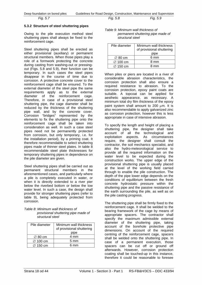
Fig. 5.7 Fig. 5.8 Fig. 5.9 5.3.2 Structure of steel shuttering pipes Owing to the pile execution method steel shuttering pipes shall always be fixed to the reinforcement cage. Steel shuttering pipes shall be erected as either provisional (auxiliary) or permanent structural members. When those pipes play a role of a formwork protecting the concrete during casting from washing-out or pressing-out (Figs. 5.8 and 5.9), their function can be temporary. In such cases the steel pipes disappear in the course of time due to corrosion. A protective concrete cover to the reinforcement cage shall be ensured. To the external diameter of the steel pipe the same requirements apply as to the external diameter of the reinforcement cage. Therefore, in case of a provisional steel shuttering pipe, the cage diameter shall be reduced by the thickness of the shuttering pipe wall, and by the concrete cover. Corrosion “bridges” represented by the elements to fix the shuttering pipe onto the reinforcement cage shall be taken into consideration as well. In such a case steel pipes need not be permanently protected from corrosion, but only temporary, i.e. for the installation period), by a priming coat. It therefore recommendable to select shuttering pipes made of thinner steel plates. In table 8 recommendable steel plate thicknesses for temporary shuttering pipes in dependence on the pile diameter are given. Steel shuttering pipes shall be carried out as permanent structural members in the aforementioned cases, and particularly where a pile is completely executed in water, or when it is directly extended to a river pier below the riverbed bottom or below the low water level. In such a case, the design shall provide for stronger shuttering pipes (refer to table 9), being adequately protected from corrosion. Table 8: Minimum wall thickness of
provisional shuttering pipe made of structural steel
Pile diameter Minimum wall thickness
of provisional shuttering pipe
∅ 80 cm 4 mm ∅ 100 cm 5 mm ∅ 150 cm 6 mm
Table 9: Minimum wall thickness of
permanent shuttering pipe made of structural steel
Pile diameter Minimum wall thickness
of provisional shuttering pipe
∅ 80 cm 6 mm ∅ 100 cm 8 mm ∅ 150 cm 8 mm
When piles or piers are located in a river of considerable abrasion characteristics, the corrosion protection shall also ensure a required resistance to abrasion. To the corrosion protection, epoxy paint coats are suitable. A topcoat can be applied for aesthetic appearance, as necessary. A minimum total dry film thickness of the epoxy paint system shall amount to 200 μm. It is also recommendable to apply galvanized zinc as corrosion protection, however this is less appropriate in case of intensive abrasion. To specify the length and height of placing a shuttering pipe, the designer shall take account of all the technological and exploitation aspects. As circumstances require, the designer shall consult the contractor, the soil mechanics specialist, and also the hydro-meteorological service to provide all the required information on the water level to be expected during the construction works. The upper edge of the provisional shuttering pipe is usually placed at the level of the working field carried through to enable the pile construction. The depth of the pipe lower edge depends on the conditions of equilibrium between the fresh concrete hydrostatic pressure within the shuttering pipe and the passive resistance of the earth surrounding the pile, as well as on the pile casting progress. The shuttering pipe shall be firmly fixed to the reinforcement cage. It shall be welded to the bearing framework of the cage by means of appropriate spacers. The contractor shall specify the maximum admissible external diameter of the shuttering pipe, taking account of the borehole protective pipe dimensions. On account of the required centring of the reinforcement cage, spacers shall be welded onto the shuttering pipe. In case of a permanent execution, those spacers can be cut off or ground off afterwards. However, corrosion protection coating shall be touched-up in this instance, therefore it could be reasonable to foresee

Guidelines for Road Design, Construction, Maintenance and Supervision Deep foundation on bored piles patented stuck-on spacers made of a synthetic material resistant to corrosion. 5.4 Design of connection of piles with
bridge substructures 5.4.1 Connection of piles with pile beam
or pile block To achieve a regular transfer of axial forces, bending moments, and shear forces from the bridge substructure members into the piles, pile beams shall be designed on the top of the piles, where the piles are arranged in a single plane, or pile blocks, where the piles are arranged in two or more planes. Pile beams and blocks are usually stiff elements of larger and reasonably determined dimensions, and of substantial load bearing capacities, ensuring a continuous flow of supporting forces from the substructure into the piles. Pile beams and blocks shall be so conceived as to enable laying of properly shaped reinforcing steel to take all the forces and moments occurring in the conceived model of piers/abutments, and to take all the local actions as well (e.g. splitting force). Pile beams shall be so designed as to be, on each side, at least 15 cm wider than the pile outer circumference. In other words, they shall be sufficiently wide, so that the reinforced core of the beam extends over the pile diameter. Where piles are constructed in difficult conditions not ensuring a correct pile position (e.g. from working fields of low bearing capacity, from pontoon systems, etc.), the pile beam shall be widened in proportion to expected deviations from the designed position. The minimum height of a pile beam is usually selected in such a way that the required anchoring or overlapping lengths or the reinforcement from piles or attached substructure members can be ensured. Where the piles are connected to a pile beam located in ground containing aggressive substances, it is recommendable to execute the pile cap 20 cm above the pile beam bottom (Fig. 5.10). The anchoring length of the reinforcement coming out from a pile and anchored into the pile beam shall be assessed on the basis of reference technical regulations and standards indicated in chapter 2. In Fig. 5.11 fundamental principles of pile beam conception are presented.
Fig. 5.10: Pile cap “plunged” into the pile
beam The pile beam reinforcement shall be so designed as to encompass the pile reinforcement completely. At least one corner-bar encompassed by the stirrup reinforcement shall reach out of the line of the force transfer from the pile into the beam, taking into account an angle of force transfer of 45°. The same also applies to the load transfer from a substructure member into the pile beam.
Fig. 5.11: Principles of pile beam reinforcing In case of transferring substantial forces into the beam, a splitting force occurs in the area where the load is introduced. Such a splitting force shall be taken by adding adequate reinforcement in a form of closed stirrups; it is also recommendable to extend the spiral reinforcement from the pile into the beam. To determine the splitting force, eventual eccentricity of the pile axial force and/or the
RS-FB&H/3CS – DDC 433/94 Volume 1 - Section 3 - Part 1 Strana 19 od 44

Deep foundation on bored piles Guidelines for Road Design, Construction, Maintenance and Supervision axial force in the attached substructure member shall be considered. The splitting force depends on the ratio of the contact area pier – beam to the contact area beam – pile. For calculation of the splitting force, empirical formulae as well as software based on finite element method are available.
Fig. 5.12: Splitting force in the pile beam Special attention shall be paid to the determination of the required reinforcement in pile beams and blocks, when piers (point supports) or walls (line supports) are supporting them out of the pile axes. In such cases it is always reasonable to verify the calculated reinforcement by applying simplified models, where an analogy of truss shall be considered (Fig. 5.13). It is also always necessary to provide an appropriate anchoring of the tensile reinforcement, as both beams and blocks are often reinforced with significant reinforcement cross-sections, which are quite difficult to be anchored properly. In such cases the reinforcement is looped, or anchor nuts or welded-on anchor plates are placed to the ends of reinforcing bars (refer to Fig. 5.13).
Fig. 5.13: Compressive and tensile “bars” in
pile beam, reinforcement anchorages
To ensure a reliable anchoring it is necessary to provide sufficient cross reinforcement (stirrups, loops, etc.), (Fig. 5.13). Instructions for the pile beam design shall be logically applied to the pile block design as well, where spatial orientation vectors of internal forces and moments shall be considered, including the presented main tensile reinforcement above the piles (Fig. 5.14).
Fig. 5.14: Primary tensile reinforcement in
usual pile blocks The reinforcement design shall also take account of the force transfer from the pier into the pile block, and the zones below the pier shall be adequately reinforced as well. In Fig. 5.14a an extension of a single pile into a pier is shown. Such solution is recommendable, when a support to place the pier formwork and/or the superstructure falsework shall be ensured. When laying reinforcement to large pile beams, a correct position of the reinforcement shall be assured. Structures to support the reinforcement shall be foreseen. They remain embedded in concrete together with the reinforcement. In case of necessity, pile beams and blocks can also be executed in ground water or surface water. Sheet piling, wells, or caissons shall be foreseen to enable the construction. 5.4.2 Direct connection between piles and
piers When bridge supports are designed as piers, standing independently, direct connections between piles and piers are frequently foreseen. Where such an extension is carried out in dry conditions, a pile is extended to a pier in the same way as it applies to shallow foundation. Some hours after the borehole protective pipe has been pulled out, the upper layer of weak concrete is chiselled off,
Strana 20 od 44 Volume 1 - Section 3 - Part 1 RS-FB&H/3CS – DDC 433/94
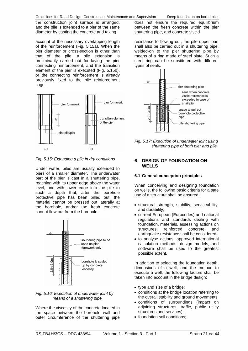
Guidelines for Road Design, Construction, Maintenance and Supervision Deep foundation on bored piles the construction joint surface is arranged, and the pile is extended to a pier of the same diameter by casting the concrete and taking account of the necessary overlapping length of the reinforcement (Fig. 5.15a). When the pier diameter or cross-section is other than that of the pile, a pile extension is preliminarily carried out for laying the pier connecting reinforcement, and the transition element of the pier is executed (Fig. 5.15b), or the connecting reinforcement is already previously fixed to the pile reinforcement cage.
Fig. 5.15: Extending a pile in dry conditions Under water, piles are usually extended to piers of a smaller diameter. The underwater part of the pier is cast in a shuttering pipe, reaching with its upper edge above the water level, and with lower edge into the pile to such a depth that, after the borehole protective pipe has been pilled out, the material cannot be pressed out laterally at the borehole, and/or the fresh concrete cannot flow out from the borehole.
Fig. 5.16: Execution of underwater joint by means of a shuttering pipe Where the viscosity of the concrete located in the space between the borehole wall and outer circumference of the shuttering pipe
does not ensure the required equilibrium between the fresh concrete within the pier shuttering pipe, and concrete viscid resistance to flowing out, the pile upper part shall also be carried out in a shuttering pipe, welded-on to the pier shuttering pipe by means of a ring made of steel plate. Such a steel ring can be substituted with different types of seals.
Fig. 5.17: Execution of underwater joint using shuttering pipe of both pier and pile 6 DESIGN OF FOUNDATION ON
WELLS 6.1 General conception principles When conceiving and designing foundation on wells, the following basic criteria for a safe use of a structure shall be ensured: • structural strength, stability, serviceability,
and durability; • current European (Eurocodes) and national
regulations and standards dealing with foundation, materials, assessing actions on structures, reinforced concrete, and earthquake resistance shall be considered;
• to analyse actions, approved international calculation methods, design models, and software shall be used to the greatest possible extent.
In addition to selecting the foundation depth, dimensions of a well, and the method to execute a well, the following factors shall be taken into account in the bridge design: • type and size of a bridge; • conditions at the bridge location referring to
the overall stability and ground movements; • conditions of surroundings (impact on
adjoining structures, traffic, public utility structures and services);
• foundation soil conditions;
RS-FB&H/3CS – DDC 433/94 Volume 1 - Section 3 - Part 1 Strana 21 od 44

Deep foundation on bored piles Guidelines for Road Design, Construction, Maintenance and Supervision
Strana 22 od 44 Volume 1 - Section 3 - Part 1 RS-FB&H/3CS – DDC 433/94
• conditions dictated by ground water actions;
• seismic conditions at the bridge location; • environmental factors such as hydrology,
surface water, settlements, seasonal humidity alterations;
• construction economy. The following shall be considered where foundation in a solid rock is foreseen: • admissible settlements of the supported
structure; • deformability and solidness of rock
masses; • presence of strata of low bearing capacity,
phenomena of rock solution, faults below wells;
• presence of contact bearing surfaces or other discontinuities, and their characteristics (e.g. filling up, continuity, width, spacing);
• weathering, decomposition, and fractures of rocks;
• damage to rock in the natural condition next to the wells.
Wells in rock are usually designed by the method of assumed contact bearing pressures. For solid intact eruptive rock, gneiss, limestone, and sandstone, the assumed pressure is limited by the compressive strength of the foundation concrete. The following design situations shall be considered in the well design: • design situation of the initial state of the
slope, existing structures, and infrastructure in the influence area prior to commencement of construction works;
• technological design situations comprising construction of access roads, working fields, excavation of well shafts, and other working stages such as prestressing of ground anchors, maintenance and eventual repairs, interventions in slopes to maintain drainage systems;
• design situations of a permanent exploitation of the structures in its design service life;
• accidental and seismic design situations. Well foundation is a method of deep foundation where the vertical shaft is excavated in a similar way, as it is usual for wells in the narrower sense of the word. The essence of the method is a gradual excavation and a simultaneous protection of the shaft circumference.
There are no essential differences between wells and piles in view of their bearing capacity and deformability behaviour. When a deep foundation is compared to a shallow one, one can establish that the interaction between the soil and the foundation is much more substantial in case of the first. The difference between both deep foundation methods is particularly in the construction method. Deep foundation is any foundation carried out to a depth greater than 6.0 m measured from the flat ground level, or from the lower side of the slope. Two excavation methods are used: • gradual excavation and simultaneous
protection of the shaft circumference (Fig. 6.1);
• gradual lowering of a well that has been previously cast above the ground level (Fig. 6.2).
By the first method, the excavation is carried out gradually in vertical segments of 0.8 to 1.5 m, and the excavated shaft circumference is protected simultaneously either with reinforced concrete rings or with shot cement concrete; in dependence on the soil quality and earth pressure magnitudes, steel rings can be foreseen in addition to the shot cement concrete. By the second method, wells are constructed at the location of excavation above the ground in a height of 2.0 m to 4.0 m. Either cast-in-situ or pre-cast solution is feasible. Both mechanized excavation and lowering the well are carried out simultaneously. After the first well segment has been lowered, the next segment is cast on the upper side, and the lowering procedure at simultaneous undermining is repeated. In the spirit of the geotechnical design in compliance with the Eurocode 7, wells are classified in the geotechnical categories 2 and 3, where wells are actually not mentioned, but their individual constituent elements indeed are. The geotechnical category 2 includes the following well elements or structural members: • foundation slabs,

Guidelines for Road Design, Construction, Maintenance and Supervision Deep foundation on bored piles • walls and other structures retaining or
supporting soil or water, • very deep wells of substantial dimensions, • excavations,
• wells where high risks or uncommon and extremely difficult ground conditions exist; • bridge abutments and piers,
• structures in areas of a significant seismic hazard;
• ground anchors and other anchoring systems.
• wells in areas of possible instabilities at the construction location, or of permanent ground movements requiring separate investigations or special measures.
The geotechnical category 3 includes structures or structural parts not covered by categories 1 and 2. Within the context of wells, the following is classified in the category 3:
1 – initial stage of excavation (working field) 2 – well excavation by stages, and by performing protection with reinforced concrete partial of complete rings (in a soil of low bearing capacity) 3 – protection of excavated shaft with shot cement concrete lining (in a weathered rock) 4 – excavating with a dredger, and removal of excavated material with a mobile crane 5 – executed well and pier (example of a hollow well) Fig. 6.1: Well execution by gradual excavation and simultaneous protection of the shaft circumference
1 – working field (provisional fill) 2 – initial well segment with a steel shoe 3 – lowering of well by undermining and construction of new well segments 4 – concrete underlay blinding (underwater concrete) 5 – execution of foundation and pier 6 – removal of well lining above the foundation
RS-FB&H/3CS – DDC 433/94 Volume 1 - Section 3 - Part 1 Strana 23 od 44

Deep foundation on bored piles Guidelines for Road Design, Construction, Maintenance and Supervision Fig. 6.2: Execution by gradual lowering of a well that has been previously cast above the ground level With regard to the way of introducing the load from a pier into the foundation soil, wells can be divided in standing (Fig. 6.3), and floating wells (Fig. 6.4). In standing wells, the complete load is transferred into the foundation soil via foundation slab or well toe. The function of the well cylinder circumference is particularly to protect the excavation, eventually to secure the pier against rock slip, to form the space around the pier, and to reduce the load indirectly. In floating wells a portion of the load is transferred into the foundation ground by friction on the cylinder circumference. In this case, a massive foundation slab is carried out on the upper side of the well shaft, or the pier is rigidly connected with the well cylinder over the entire shaft height. Foundation on wells can be carried through either of individual wells of circular or elliptical cross-section, or of a group of wells, i.e. two to four wells being rigidly interconnected by a slab or a crossbar. Wells executed by gradual excavation and simultaneous protection, are usually of a circular or elliptical cross-section. Both the shape and dimension of a well particularly depends on the dimension and shape of the pier, order of magnitude of static actions, ground stability conditions, and height or depth of the well. For wells carried out by gradual lowering, a rectangular or square cross-section can also be designed. In view of dimensions of the well cross-section no fixed restrictions exist. Where the well excavation is protected with shot cement concrete, the well diameter shall be generally limited to 2.0 or 2.5 m. Namely, the required working area for both excavation and application of shot cement concrete depends on the well diameter. In the constructional practice, executed wells of D = 2.0 m are known. There are practically no limitations regarding the maximum cross-sectional dimensions of a well. Wells of elliptical cross-section of dimensions 21.0 x 15.0 m are known.
Fig. 6.3: Standing well
Fig. 6.4: Floating well To conceive a well, two principles can be adopted: an ideally stiff or an ideally flexible (deformable) structure (Fig. 6.5). A stiff well structure is a monolithic continuous reinforced concrete cylinder, resistant to bending, whilst a flexible well structure is created by well cylinder elements (rings) interconnected by means of sliding expansion joints.
Strana 24 od 44 Volume 1 - Section 3 - Part 1 RS-FB&H/3CS – DDC 433/94

Guidelines for Road Design, Construction, Maintenance and Supervision Deep foundation on bored piles
1 - protection of excavation 1a - reinforced concrete semi-rings with or without passive anchors 1b - reinforced concrete rings at gradual excavation 1c - excavation protection with shot cement concrete 2 - well toe – contact between well bottom and bearing ground 3a - filling up with partly reinforced concrete 3b - filling up with gravel
4 - foundation block (pier rigidly connected to the well) 5 - pier 6 - well circumference wall 6a - well cylinder elements interconnected by means of expansion joints 6b - trapezoidal element of the well cylinder 6c – inclined sliding rings of the well cylinder
RS-FB&H/3CS – DDC 433/94 Volume 1 - Section 3 - Part 1 Strana 25 od 44

Deep foundation on bored piles Guidelines for Road Design, Construction, Maintenance and Supervision Fig. 6.5: General principles of well design for viaduct piers A stiff structure is advantageous for the explicit stability of its shape, and a relatively low sensitivity to local discontinuities and non-homogeneities in the foundation soil, whereas a flexible structure is favourable for the fact that earth pressures acting on the well are lower, thus the well wall thickness can be reduced. At relatively substantial movements due to slope sliding, and at periodical intensive discontinuous slips, such a well is economical to a depth of 15 – 20 m. At greater depths it is more favourable to foresee a deformable well cylinder. A mixed principle is often designed taking account of economy as well as of the static and kinematical behaviour of the well cylinder circumference. The well depth (height) particularly depends on the depth where a load bearing soil is located. It is important to fix the well into a relatively sound load bearing rock. “Floating” wells are only exceptionally used in cases where the rock is practically unattainable. In general, at depths of 15 – 18 m the well construction costs increase substantially, in particular for the aggravated vertical transport of the material excavated. Up to those depths, and at adequate cross-sectional dimension of the well, the excavated soil is transported upwards by means of a hydraulic dredger equipped with an extended arm. At greater depths, the excavated material is transported with a mechanical dredger. Maximum well depths amount to 30.0 – 35.0 m. 6.2 Structural elements of excavation
protection The thickness of the shot cement concrete lining (Fig. 6.6) executed to protect the well shaft at gradual excavation depends on the foundation soil conditions and the selected well cross-section. For habitual well dimensions it amounts to 10 – 15 cm. The lining can be partly non-reinforced, however it is usually reinforced with mesh reinforcement placed in two layers. As circumstances require, steel braces can be foreseen at greater depths. On the top of the well, a reinforced concrete ring is carried out, increasing stability against the earth pressures, which act from one side only. In the lowest excavation layers, where a solid rock is present, the shaft circumference needs not urgently be protected with shot
cement concrete (Fig. 6.6), on condition that the well toe is immediately cast after the foundation surface has been manually cleaned. Excavated well shafts shall be protected with cast-in-situ reinforced concrete rings (Fig. 6.7), where well of larger diameters are located in a soft soil, and in particular, when the well is later on not filled up with concrete. The excavation depths for individual segments depend on actual soil properties and well cross-section, and generally amount, with regard to the working-technical conditions, 1.0 to 1.5 m. In a soil of low cohesion, the excavation depth has often to be reduced to 0.2 – 0.3 m to prevent crumbling of the soil. In hollow wells, after the foundation toe is completed, the wall of the well shall be constructed in a thickness of 30 – 60 cm, which depends on the earth pressure magnitude.
Fig. 6.6: Protection of excavated well shaft with shot cement concrete lining 6.3 Foundation block and design of
contact between well toe and foundation bottom
The well shall be fixed into the bearing ground in a thickness of 1.50 – 2.50 minimum. A widened well toe is reasonable particularly in cases where the well is surrounded by non-cohesive material and weaker rock; where a well is fixed in a solid rock, such a measure is not required. Consequently, one shall commence to execute the cross-sectional widening in the area of non-cohesive soil, where it is
Strana 26 od 44 Volume 1 - Section 3 - Part 1 RS-FB&H/3CS – DDC 433/94

Guidelines for Road Design, Construction, Maintenance and Supervision Deep foundation on bored piles indispensable to know the final well depth in advance. When a well is fixed into the rock at a greater depth, a spread load transfer into the foundation soil shall be achieved by friction between the jagged cylinder circumference and the rock. In case of a greater inclination of the rock base, the foundation toe can be so executed as to have
steps at the contact between the well and the solid rock. A better connection between the well toe and the foundation soil can be achieved by means of vertical anchors (Fig. 6.8).
Fig. 6.7: Excavation protection with reinforced concrete rings
RS-FB&H/3CS – DDC 433/94 Volume 1 - Section 3 - Part 1 Strana 27 od 44

Deep foundation on bored piles Guidelines for Road Design, Construction, Maintenance and Supervision
Fig. 6.8: Examples of well toe design 6.4 Methods of connecting a pier with a
well Where a pier is fixed into the well top, a solid well (Figs. 6.5a, 6.5b, and 6.9) shall be constructed. Such a solution is appropriate in the following cases: • for wells of smaller diameters (< 4.0 – 5.0
m); • for wells of larger diameters, and heights
up to 6.0 – 10.0 m; • where there is not enough space between
the pier and the well, thus the well diameter should be increased;
• where this is admitted by the pier height in view of taking horizontal loads;
• at a presence of greater amounts of water.
The well shall be filled up with a filling, partially reinforced concrete, or the well cylinder is executed of reinforced concrete and filled up with gravel. Filling-up with gravel shall be foreseen in case of greater depths and larger cross-sections of wells, where filling-up with concrete would not be economical. Drainage shall be arranged in the pier area on the top of the well. In hollow wells (Figs. 6.5c, 6.5.d, and 6.10), a pier is fixed into the foundation block of the well toe particularly in the following cases: • where it is necessary to reduce the pier
stiffness by increasing its height; • in an unstable slope where the well cylinder
is carried out as a protective structure.
Strana 28 od 44 Volume 1 - Section 3 - Part 1 RS-FB&H/3CS – DDC 433/94

Guidelines for Road Design, Construction, Maintenance and Supervision Deep foundation on bored piles
Fig. 6.9: Constructive particularities of a solid well
RS-FB&H/3CS – DDC 433/94 Volume 1 - Section 3 - Part 1 Strana 29 od 44

Deep foundation on bored piles Guidelines for Road Design, Construction, Maintenance and Supervision
Fig. 6.10: Constructive particularities of a hollow well In bridges, an individual pier can be founded either on a single well or on two or more wells interconnected by a stiff beam or slab. A foundation on more wells is advantageous, as the efficiency of the latter is greater for the effect of a frame. A further advantage is, that in case of executing wells of smaller diameters it is easier to ensure the stability during shaft excavation comparing to an individual well of a larger diameter. However, from the point of view of construction works, it is less favourable to carry out a greater number of smaller wells than a larger single well. A pier foundation on several wells of smaller diameter is economical for depths of up to 10.0 m. In a steep slope, wells of two adjoining piers can be interconnected with a stiff crossbeam, thus forming a frame structure to take the load arising from the earth pressure (Fig. 6.11). For pier foundations in a steep slope consisting of greater thicknesses of non-bearing strata it is economical to design a common well of a larger elliptical cross-section for two piers of two parallel superstructures. On the top of the well, a stiff
crossbeam shall be executed to provide a connection with the piers. 6.5 Anchoring a well in unstable ground Wells shall be anchored where foundation is carried out in a steep unstable slope. For excavation purposes it is often required to anchor semi-rings at an early excavation stage, when a cut is formed in the slope and the protection cannot yet be performed with full rings. In this part, semi-rings shall be constructed in combination with passive or prestressed anchors, depending on the earth pressure magnitude (Fig. 6.13).
Strana 30 od 44 Volume 1 - Section 3 - Part 1 RS-FB&H/3CS – DDC 433/94
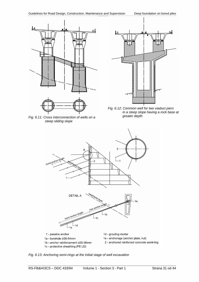
Guidelines for Road Design, Construction, Maintenance and Supervision Deep foundation on bored piles
RS-FB&H/3CS – DDC 433/94 Volume 1 - Section 3 - Part 1 Strana 31 od 44
Fig. 6.11: Cross interconnection of wells on a steep sliding slope
Fig. 6.12: Common well for two viaduct piers
in a steep slope having a rock base at greater depth
Fig. 6.13: Anchoring semi-rings at the initial stage of well excavation

Deep foundation on bored piles Guidelines for Road Design, Construction, Maintenance and Supervision In a sliding slope the well stability can sometimes be ensured by permanent ground anchors. In steep sliding slopes, where sudden slips of the rock may occur, it is often uneconomical to protect the whole slope in order to prevent movements completely. It is necessary to focus on individual piers and to ensure local safety to the required extent. It shall be taken into account that, in case of movements towards the slope foothills, load concentrations into the fixed area of a pier occur. In general, two possibilities to take those load concentrations exist: they can be taken either completely by massive supporting walls or by anchoring the well. The anchoring can be carried out on the front side of the well towards the slope, or anchors are installed on the valley side of the pier. It is also possible to anchor the well itself. By means of a prestressed anchor placed onto the top of a well it is possible to take a part of horizontal forces and to reduce bending moments in the well effectively. In areas of a high hazard, anchors shall also be placed at additional levels of the well cylinder (Fig. 6.14). Such a method is only foreseen exceptionally for the following negative factors: • slowing down the construction;
• complex static systems due to the construction in stages, and an approximate consideration of earth pressure redistribution (introduction of concentrated load);
• aggravated possibility to check the prestressed anchor capacity, e.g. by means of an extensometer or anchor force measuring cell at the well cap;
• inability of replacing an anchor failed due to corrosion or rupture, and an additional anchor can only be installed at the well or in the well cap;
• reduction of ground reactions on the valley side.
Such ground anchors are advantageous, which anchorages are located on the top of a well, or of a crossbeam interconnecting two wells, where a pier is founded on two or more wells. In such a case, it is quite simple to supervise the anchors, and any failed anchor can be replaced. For this purpose, sufficient space for spare anchors shall be foreseen. An abutment can be secured by anchoring the slope (foundation earth body) on the valley side (Fig. 6.15). Anchor shall be prestressed to 2/3 of the service load, and grouted with cement mortar, which the cracked rock is simultaneously strengthened with.
Fig. 6.14: Example of anchoring a well; anchorages located at several levels
Strana 32 od 44 Volume 1 - Section 3 - Part 1 RS-FB&H/3CS – DDC 433/94

Guidelines for Road Design, Construction, Maintenance and Supervision Deep foundation on bored piles As securing of slope with anchors is quite expensive, it is more reasonable to deepen the particular well. In comparison with anchoring at levels in the well cylinder, anchors arranged on the valley side outside the well have the following advantages: • reduction of ground reaction forces
(stresses), as well as prevention of soil breaking up and slips on the valley side of a well;
• diminishing forces and moments in a well, where no concentrated introduction of forces at anchoring levels takes place.
Fig. 6.15: Anchoring a well and an abutment in a steep slope 6.6 Particularities of a well executed by
lowering The conception of a well structure executed by lowering (sinking) is conditioned by the construction method and by the properties of non-bearing foundation soil strata, through which a well is being lowered. A hollow well of either a square/rectangular or circular/elliptical cross-section with or without separated chambers (Fig. 6.16), shall be carried out in-place above the working field in several segments or in a single piece. A prefabricated construction is also feasible. When an artificial fill in water is correctly executed, an intensive water inflow is only possible through the well bottom. In such a case water shall be pumped out by means of high-capacity pumps, or tightening shall be performed by means of a high-pressure grouting. A well is carried out in stages during lowering in the following cases: • at a great depth and a small width
(diameter) of a well, i.e. H/B > 1.3; • when the dredger or crane arm height is
limited to Δh/h < 2, where Δh signifies the
height of the construction stage, and h is the height of the dredger or crane arm;
• where soft clay is located directly below the working field.
A well is executed to a full height above the working field in the following cases: • at a small depth and a great width
(diameter) of a well, i.e. H/B < 1.3; • when the dredger or crane arm height is
limited to h < 2/3 H, where H signifies the well height, and h is the height of the dredger or crane arm;
• where a solid clay or sand are located next below the working field;
• in case of heavy wells, which cannot be brought to a standstill by means of stopping devices.
A well structure, which is not executed by lowering, consists of a cutting edge, a rim, and walls. A cutting edge with a rim (Fig. 6.17) on the lower side of the well enables the following: • a direct transfer of the pressure, resulting
from the well dead weight, onto the soil during the lowering process;
• a protection of the well at unsymmetrical loading due to obstacles during lowering;
• an easier excavation of the soil. A cutting edge is required at lowering the well through a solid soil, and through strata comprising obstacles. It shall be sufficiently stiff as not to represent an obstacle during lowering the well. A rim shall have the following characteristics: • it shall ensure a sufficient support to the
cutting edge, which is a direct contact with the ground and exposed to local loading due to obstacles at lowering the well;
• its cross-sectional shape shall be a trapezium, where the inclination of the inner side to the vertical is reduced in case that the soil is solider;
• onto the rim, a cutting edge in a form of a chopper is fixed to increase the effect of cutting into soil.
Well walls shall implement the following functions: • to play a protective role during lowering the
well; • to take all the loading occurring during
lowering and transportation; • to enable by their mass, that a well can
sink automatically by overcoming the friction in the ground below the cutting edge on the lower side of the well.
RS-FB&H/3CS – DDC 433/94 Volume 1 - Section 3 - Part 1 Strana 33 od 44

Deep foundation on bored piles Guidelines for Road Design, Construction, Maintenance and Supervision Into the well walls all the installation ducts shall be built-in, which are necessary to perform corrective measures during lowering.
In the cutting edge area, pipes are installed to enable rinsing of the cutting edge in case that the latter has stuck.
Fig. 6.16: Possible shapes of wells executed by lowering
Fig. 6.17: Shaping of the well lower part including a cutting edge
Strana 34 od 44 Volume 1 - Section 3 - Part 1 RS-FB&H/3CS – DDC 433/94

Guidelines for Road Design, Construction, Maintenance and Supervision Deep foundation on bored piles
RS-FB&H/3CS – DDC 433/94 Volume 1 - Section 3 - Part 1 Strana 35 od 44
7 GEOSTATIC ANALYSIS OF
BORED PILES 7.1 Input data 7.1.1 General The intention of a geostatic analysis being a constituent part of the analysis of the entire load bearing structure is to verify structural reliability, which includes safety, serviceability, and durability of a structure founded on bored piles. Such an analysis is a mandatory constituent part of a building permit design. When conceiving and designing structures founded on bored piles, approved methods of structural and foundation soil analysis are used taking account of the interaction between both load-bearing systems. A static analysis includes the following: - information on geometry of both structure
and foundation soil; - information on materials of which
foundation and structural members are constructed;
- data on properties of soils and rocks of the foundation ground;
- actions that can be loads, (or) movements, and (or) accelerations in different directions;
- design models and (or) results of field load testing;
- limiting values of deformations, crack widths, vibrations, etc.
The analysis takes account of both characteristic and design values of actions. 7.1.2 Limit states When analysing a structure, including foundations, the design engineer is obliged to verify the limit states indicated below. Ultimate limit states (denotations in compliance with the prEN 1990 are adopted): - The STR limit state deals with the internal
failure or excessive deformation of a structural element including foundations, where the material strength prevails in the bearing resistance verification.
- The GEO limit state deals with the danger of failure or excessive deformation of the ground where the strength of soils and rocks is important to ensure resistances.
- The STA limit state deals with the loss of the overall stability or with an excessive
deformation of the entire structure – foundation soil system.
- The UPL limit state deals with the failure by uplift of the foundation soil due to vertical forces, resulting from the vertical non-equilibrium of the structure or earth masses.
- The HYD limit state deals with the ground failure due to hydraulic gradients.
Limit values of foundation displacement: - In the analysis, limit values of bored pile
foundation displacement are assessed, representing those displacement values, which still ensure the required safety from activating limit states of the supported structure.
7.2 Bearing capacity of piles loaded with
axial force 7.2.1 General The geostatic analysis of foundation on bored piles is limited to assessing both “external” and “internal” load bearing capacity of a pile. While the “internal” bearing capacity of a pile can be exactly calculated using equations, which apply to assessing bearing capacity of circular cross-sections, the assessment of its “external” bearing capacity, i.e. a capacity provided by the foundation soil to be in contact with a pile, requires a good knowledge of actual foundation soil properties and mechanisms of load transfer into the foundation soil. The bearing capacity depends on the accuracy of both field and laboratory investigations, as well as on a series of empirical parameters. As a consequence, the calculated bearing capacity can substantially differ from the actual one. By all means, the most reliable information can be obtained by investigating test piles or performing other field examinations, which, however, are very expensive, thus they are only reasonable in case of a large number of piles, and for complex structures where the investigation expenses are justified by savings in foundation works, as reduced safety factors can be introduced. For empirically assessed pile bearing capacities a lower reliability of calculated results is taken into account by suitable safety factors.
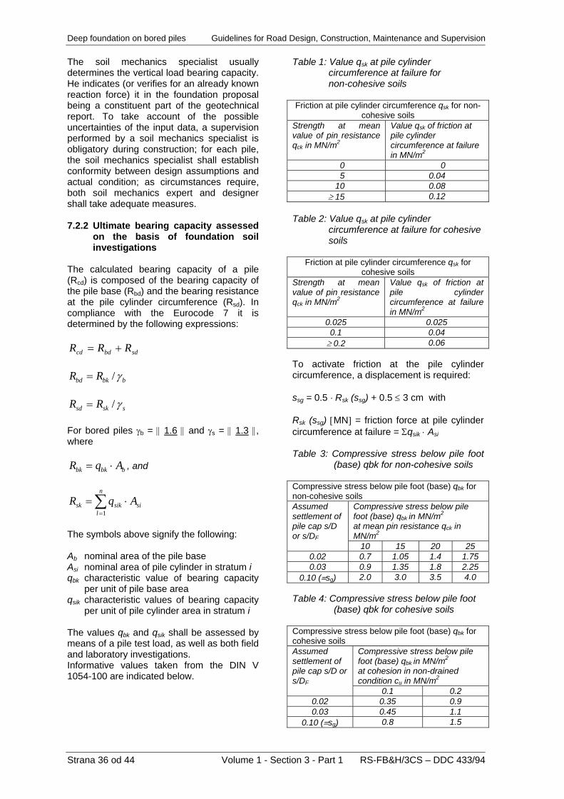
Deep foundation on bored piles Guidelines for Road Design, Construction, Maintenance and Supervision The soil mechanics specialist usually determines the vertical load bearing capacity. He indicates (or verifies for an already known reaction force) it in the foundation proposal being a constituent part of the geotechnical report. To take account of the possible uncertainties of the input data, a supervision performed by a soil mechanics specialist is obligatory during construction; for each pile, the soil mechanics specialist shall establish conformity between design assumptions and actual condition; as circumstances require, both soil mechanics expert and designer shall take adequate measures.
Strana 36 od 44 Volume 1 - Section 3 - Part 1 RS-FB&H/3CS – DDC 433/94
7.2.2 Ultimate bearing capacity assessed
on the basis of foundation soil investigations
The calculated bearing capacity of a pile (Rcd) is composed of the bearing capacity of the pile base (Rbd) and the bearing resistance at the pile cylinder circumference (Rsd). In compliance with the Eurocode 7 it is determined by the following expressions:
sdbdcd RRR +=
bbkbd RR γ/=
ssksd RR γ/= For bored piles γb = || 1.6 || and γs = || 1.3 ||, where
bbkbk AqR ⋅= , and
si
n
lsiksk AqR ⋅= ∑
=1
The symbols above signify the following: Ab nominal area of the pile base Asi nominal area of pile cylinder in stratum i qbk characteristic value of bearing capacity
per unit of pile base area qsik characteristic values of bearing capacity
per unit of pile cylinder area in stratum i The values qbk and qsik shall be assessed by means of a pile test load, as well as both field and laboratory investigations. Informative values taken from the DIN V 1054-100 are indicated below.
Table 1: Value qsk at pile cylinder
circumference at failure for non-cohesive soils
Friction at pile cylinder circumference qsk for non-
cohesive soils Strength at mean value of pin resistance qck in MN/m2
Value qsk of friction at pile cylinder circumference at failure in MN/m2
0 0 5 0.04 10 0.08 ≥ 15 0.12
Table 2: Value qsk at pile cylinder
circumference at failure for cohesive soils
Friction at pile cylinder circumference qsk for
cohesive soils Strength at mean value of pin resistance qck in MN/m2
Value qsk of friction at pile cylinder circumference at failure in MN/m2
0.025 0.025 0.1 0.04 ≥ 0.2 0.06
To activate friction at the pile cylinder circumference, a displacement is required: ssg = 0.5 ⋅ Rsk (ssg) + 0.5 ≤ 3 cm with Rsk (ssg) [MN] = friction force at pile cylinder circumference at failure = Σqsik ⋅ Asi Table 3: Compressive stress below pile foot (base) qbk for non-cohesive soils Compressive stress below pile foot (base) qbk for non-cohesive soils
Compressive stress below pile foot (base) qbk in MN/m2
at mean pin resistance qck in MN/m2
Assumed settlement of pile cap s/D or s/DF
10 15 20 25 0.02 0.7 1.05 1.4 1.75 0.03 0.9 1.35 1.8 2.25
0.10 (≡sg) 2.0 3.0 3.5 4.0 Table 4: Compressive stress below pile foot (base) qbk for cohesive soils Compressive stress below pile foot (base) qbk for cohesive soils
Compressive stress below pile foot (base) qbk in MN/m2
at cohesion in non-drained condition cu in MN/m2
Assumed settlement of pile cap s/D or s/DF
0.1 0.2 0.02 0.35 0.9 0.03 0.45 1.1
0.10 (≡sg) 0.8 1.5

Guidelines for Road Design, Construction, Maintenance and Supervision Deep foundation on bored piles The following approximate relation applies to the pin resistance: qc [MN/m2] ≈ N10, where N10 is the number of strokes to impress a heavy pin by 10 cm into the foundation soil. 7.3 Bearing capacity of piles loaded with
horizontal force 7.3.1 General The horizontal force, i.e. a force acting perpendicularly to the pile axis, shall only be applied to piles of large diameters being capable to take substantial bending moments. In such a case, lateral elastic earth resistance is activated, thus a model of a bar stiff to bending and supported by the surrounding earth body occurs. To calculate bending moments of piles due to horizontal forces empirical equations by different authors exist, derived from differential calculus for an elastic body supported by an elastic earth body. Those equations are appropriate to approximate verifications, particularly at an early design stage, i.e. conceptual design. In recent 20 years approved models are used to analyse forces and moments by introducing relatively simple software based on elastic springs, which simulate flexibility of foundation soil strata. All the up-to-date software for structural analysis already contains a module to analyse the ground elastic response for any direction in space; tensile reaction forces in the ground are eliminated automatically. 7.3.2 Analysis of effects of actions due to
horizontal forces In view of the fact that a state-of-the-art design of bridges founded on piles of large diameters requires reliable and certified software, instructions and requirements for preparation of design models and for verification of calculated results of the FEM analysis are indicated below. In any case, such design models are recommendable, which consider the entire structural load bearing system as an integrity thus ensuring a direct interaction between the bearing structure and foundation.
Fig. 7.1: Bridge arrangement and a common model for a complex analysis of effects of actions due to vertical and horizontal forces in bridge axis direction To work out a model for an analysis of effects of actions due to horizontal forces, the structural design engineer shall consider very thoroughly the conformity between the design model and the actual condition during construction; he shall also foresee all possible changes at the location, which could result in a modification of the design model. In particular errors and also quick changes of conditions of fixing the piles in the upper strata are possible. The design model shall urgently take account of the influence of adjoining piles within a group of piles as well (Fig. 7.1). Slopes at abutments shall be designed very cautiously, as no mobilization of the elastic resistance is usually ensured in the upper part of piles (Figs. 7.1, 7.2); alike, a subsequent remodelling of the slope or the earth body at piles (river erosion, depressions, soil soaking, removal of earth due to construction of other structures, etc.) essentially affect the conditions of fixing the piles. Such impacts are particularly critical in bored piles of insufficient lengths.
RS-FB&H/3CS – DDC 433/94 Volume 1 - Section 3 - Part 1 Strana 37 od 44

Deep foundation on bored piles Guidelines for Road Design, Construction, Maintenance and Supervision
Fig. 7.2: A correct consideration of mobilized resistance. Above the line of the mobilized resistance it is not possible to expect an elastic fixity of a pile The aforementioned possible causes of the change of conditions to fix abutment piles are only a small fragment of complex problems to be taken into account by the design engineer. Especially at locations, which are difficult to execute foundations, it is essential to take account of the actual condition and eventual subsequent events during construction and service, as this provides extremely important information to conceive a foundation on bored piles. The designer shall consider all the available data, to cooperate with other relevant experts, and to specify the additional investigations and analyses required. 7.3.3 Analysis of results A verification of results of a computer aided calculation method is an indispensable element of the structural analysis. The correctness of boundary conditions and assumptions having been introduced into the calculation shall be checked; it shall also be established whether the structural response is within the admissible parameters. The most important steps are the following: - to check bending moments, - to check the shapes of strain lines and
absolute values of displacements (significant displacements mean that the assumption of an elastic behaviour has failed),
- to check supporting forces in foundation soil (or contact pressures at the pile cylinder circumference), which are limited due to shear failure mechanisms in the ground; attention shall also be paid to eventual tensile forces in the foundation ground.
As circumstances require, the analysis shall be carried out by several iterations, where an aspiration for searching for situations on a “less safe side” has to be emphasized. By varying input data such as pile fixity depths or elastic properties of earth strata all the limits of the assumptions, which are extremely scattered in difficult foundation conditions, are verified. 7.4 Bearing capacity of piles arranged in a
group Usually, a bridge pier is founded on several bored piles arranged in a group and interconnected by means of a pile beam or a pile block. As the pile spacing is limited for constructive reasons in conceiving pier elements, pile interactions cannot be avoided. In standing piles, which vertical bearing capacity is ensured by the resistance below the pile foot, the influence of a group is relatively insignificant. In piles however, where the bearing capacity is partly or entirely ensured by friction at the pile cylinder circumference, the influence of a group of piles becomes substantial. The same also applies to the pile horizontal bearing capacity. The problems of bearing capacity of piles arranged in a group shall be considered integrally; therefore, the majority of computer software, used by bridge designers, fails. Both conception and analysis shall take account of the influence of a group of piles; in simple foundation conditions order of magnitude of that influence shall be verified, using computer software or empirical methods reasonably. In case of a more complex foundation, an expert in stability analyses shall be engaged. 8 GEOSTATIC ANALYSIS OF WELLS Stability (reliability) verification of wells is a constituent part of the bridge stability verification, where principles of the geotechnical design in compliance with the Eurocode 7 shall be taken into consideration. The term reliability comprehends structural safety, serviceability, and durability.
Strana 38 od 44 Volume 1 - Section 3 - Part 1 RS-FB&H/3CS – DDC 433/94

Guidelines for Road Design, Construction, Maintenance and Supervision Deep foundation on bored piles 8.1 Design models In structural modelling and considering correct loads some uncertainties in modelling foundations or structural members below the pier lower edges occur, in particular in frame structures. The reason is an uncertain assessment of the ground behaviour particularly in Alpine and mountainous regions, where the ground properties change at relatively short distances. In statically indeterminate systems any change of pier boundary conditions causes a change of internal forces and moments, thus the uncertainty of the assessment of the foundation soil properties is transmitted to the whole system. Up-to-date computer programs enable more and more accurate structural modelling, where, however, the correctness of the structure – soil interaction depends on the input data reflecting the actual conditions. The following methods of structural modelling are used in the design practice: • bearing structure and wells are modelled
separately; • bearing structure and wells are modelled
jointly. The simplest model of a well and the earth foundation body is illustrated by means of a stiff-plastic model (Fig. 8.1) with selected design shear strength of the soil (with parameters c’ and ϕ’), and with a stiff model of a well.
Fig. 8.1: Stiff-plastic model of a well A base for such a model is the well kinematics prescribed in advance, and the limit or prescriptive design stress state in the soil. The model enables a relatively simple assessing the limit values of actions and resistances (active and passive earth pressures, and bearing capacity of the foundation soil), whilst the activated portions of those values shall be estimated in view of expected or admissible deformations of both substructure and ground in the influence area. However, actual displacements cannot be calculated using this model.
In practice, a model based on the module of ground reaction is most frequently used. A well is modelled as a bearing element (1D, 2D, or 3D) supported from the point, where a zero difference between active and passive earth pressures is foreseen (Fig. 8.2), by means of springs, which constants are determined on the basis of the module of ground reaction k [kN/m3]. The latter is assessed by investigations, i.e. a horizontal test with a slab, a pressiometric examination, etc. It is defined as a proportionality factor of the normal stress and displacement of the abovementioned point (σ = k ∗ w). In a simplified form and taking account of the theory of an elastic isotropic earth body, the module of the ground reaction perpendicularly to the well is equal (by Terzaghi): kh = χ ⋅ Ms / b , where χ = correction factor (0.6 – 1.4, usually 1.0), Ms = module of the soil compressibility b = width of the well
Fig. 8.2: Model of a well in a slope on the
basis of the module of ground reaction
To analyse limit states of the pile well circumference, simplified 1D-model of an elastically supported ring can be used (Fig. 8.3), as it is known in the tunnel design. More accurate are elasto-plastic models enabling analysis of design situations by taking account of the entire influence area of the foundation soil body. In such a model, the foundation soil properties are considered by means of elasto-plastic constitutive models. A well is modelled by elastic or elasto-plastic 2D- or 3D-elements.
RS-FB&H/3CS – DDC 433/94 Volume 1 - Section 3 - Part 1 Strana 39 od 44

Deep foundation on bored piles Guidelines for Road Design, Construction, Maintenance and Supervision
Fig. 8.3: 1D-model of well circumference 8.2 Assessment of actions on wells To analyse limit states correctly, actual actions shall be assessed, as well as their distribution taking account of the well structure – ground interaction. The following actions are in question: • loads and combinations of loads on a
bridge bearing structure, which are transferred into the well via piers and abutments: permanent loads, effects of prestressing, concrete creep and shrinkage, traffic load, uniform and non-uniform temperature variation, wind load, braking force, friction in bearings free in one or more directions, seismic load;
• actions on a well: dead weight of a well, earth pressure, movements and accelerations due to earthquake, ground water pressures, filtration pressures;
• reaction forces action on a well: friction between the soil and the well circumference, pressures on the well bottom slab, friction between the bottom slab and the ground, reaction forces on the well circumference, earth resistance, buoyancy;
• forces arising from anchors; • movements due to weathering,
decomposition, natural settlement, and soil solution;
• movements due to creeping, sliding, or settling of ground masses;
• movements due to other excavations or construction of adjoining wells.
8.3 Load due to earth pressure In a stable ground being at rest, the horizontal pressure on the slope side is equal to the earth pressure at rest:
σh = K0 ⋅ σv ; σv = γ ⋅ z σv ... vertical stress at depth z z ... depth of a well γ ... specific gravity of soil K0 ... coefficient of the earth pressure at rest K0 =(1 + sin(ϕ−β)) On the valley side, passive earth pressure is activated due to the established equilibrium. To assess the earth pressure acting on the well circumference at the stage of excavation works, local redistribution of the pressures can be taken into account. The horizontal earth pressure is redistributed around the shaft due to forming of both horizontal and vertical arch in the soil. The vertical arch in the soil disappears during subsequent excavation stages, whereas the influence of the horizontal one persists even after completion of the well shaft:
hR A σσ ⋅=
A = reduction factor; if the cohesion is not considered, the reduction factor amounts to:
ϕ
ϕ
tan
1tan
⋅
−=
−
rzeA
rzKa
Ka = coefficient of the active earth pressure
2
2
cos)sin(sin1
cos
⎟⎟⎠
⎞⎜⎜⎝
⎛ −⋅+
=
ββϕϕ
ϕaK
β = slope inclination angle ϕ = angle of internal friction in soil r = well radius In floating wells the vertical friction is given by the following expression:
ϕστ tan32
⋅⋅= RR
In wells of larger diameters and with protective curved walls on the slope side of the well, the influence width of earth pressures shall be considered as follows: • b´ = 1.2 B to 2.0 B; B = width of the well
Strana 40 od 44 Volume 1 - Section 3 - Part 1 RS-FB&H/3CS – DDC 433/94

Guidelines for Road Design, Construction, Maintenance and Supervision Deep foundation on bored piles The design influence width (Fig. 8.4) depends on the slope inclination angle, soil properties, and well geometry. In wells located in sliding slopes, the earth pressure is gradually increasing from the active earth pressure over a “standstill” pressure to the pressure at soil yielding (plasticity zone), and a full sliding pressure at forming a sliding surface.
Fig. 8.4: Determination of the influence width 8.4 Ultimate limit states and serviceability
limit states Design situations shall be analysed by means of design models of both structure and foundation soil. By analysing individual design situations it shall be verified that no ultimate limit state, serviceability limit state, and durability limit state will be exceeded in the entire service life of the well. In the spirit of geotechnical design the following limit states need to be verified: • overall stability limit states • GEO limit states • STR limit states The limit state of the overall stability deals with the soil mechanical conditions of loss of overall stability, or of excessive ground deformations, where the soil and rock strength is the most important feature to ensure resistances. For the well design and execution, overall stability of the influence area in all the analysed design situations shall be verified. Overall stability of the well, of the earth slope both above and below the well, of access roads, excavations, and working fields, which are conditioned by the construction technology, shall be verified.
When selecting adequate methods to verify overall stability limit states the following shall be considered: stratification of slopes, phenomena and directions of discontinuities, ground water seepage and pore pressures, conditions of short-term and long-term stability, deformations due to shear stresses, and suitability of the model of analysis of potential failure. By the GEO limit state, sufficient safety (geotechnical safety) is verified for ultimate limit states of the slope and the foundation soil in the well area, such as: ground failure due to actions on wells, failure due to slip, anchor failure, etc. By the STR limit state, sufficient bearing capacity of individual well structural members (wall to protect the slope below the well, well circumference, bottom slab, fixity of the pier into the well, etc.) is verified for individual design situations. Forces and moments in the wall of the well are usually assessed according the 2nd order theory taking account of the elasto-plastic behaviour of rings. When dimensioning the well circumference both instability criterion (deflection) of the wall and limitation of deformations shall be considered. For individual design cases it shall be verified that, at a limit state, a limit equilibrium state of design actions and resistances can be established, and that the deformations are sufficiently small at the particular limit state. In selecting design values of limit movements, the influence of the latter on the entire bridge structure shall be taken into consideration. For more complex concrete structural members limit states of cracks shall be verified, and an argumentation of expected events in inaccessible areas and in areas of foreseen construction joints shall be provided. 9 EXECUTION OF FOUNDATION ON
BORED PILES The fundamental steps to execute a bore pile of a large diameter are as follows: - supporting/retaining of the wall of the pile
borehole (shaft, excavation), - soil or rock excavation, - depositing excavated material. The method of supporting/retaining the shaft wall against crumbling depends particularly on the foundation soil properties, and on the selected boring technology.
RS-FB&H/3CS – DDC 433/94 Volume 1 - Section 3 - Part 1 Strana 41 od 44

Deep foundation on bored piles Guidelines for Road Design, Construction, Maintenance and Supervision
Strana 42 od 44 Volume 1 - Section 3 - Part 1 RS-FB&H/3CS – DDC 433/94
Three main methods exist: - placing shaft protective pipe, - supporting/retaining by flushing liquid, - without any supporting/retaining. Excavation in the borehole is carried out by cutting and digging in light soil, by tearing and chiselling in semi-solid soil, and by breaking in semi-solid and solid rock. In the market there are several types of boring sets available, by means of which this type of foundation is mastered at high technical reliability and an optimum economy. Deep foundation on piles rarely exceeds a depth of 30 m, and it is usually executed in very heterogeneous strata. Pile foot is usually located in a rock base or in layers of compacted sands. In such conditions contractors are equipped particularly to carry out excavations in boreholes protected with pipes. Where soil properties are favourable, protective pipes can be omitted in case that boring is performed by means of spiral spindles. Boring works shall be carried through by specialized contractors having at their disposal up-to-date equipment and experienced experts being able to select the most appropriate technology, taking account of project specificities and geological conditions at construction site. Supervision of bored pile execution is extremely important to ensure all the essential requirements to be fulfilled by a newly constructed bridge. All the foundation works are carried out in environment, which is inaccessible and can be supervised neither visually nor with instruments requiring a direct contact with a structural member. The execution is often associated with aggravated conditions of underwater concreting, water streaming, and difficult placing of machinery to carry out a pile. Common methods of taking-over the construction pit bottom are not feasible, thus irreproachability of the entire pile, including its contact with the foundation ground, can only be checked by special methods and equipment. The branch of profession has developed numerous methods of testing the pile reliability. An essential requirement to be implemented by those methods is a reliable evidence of the pile continuity, i.e. an ascertainment whether a pile foot is standing on an intact base, and whether any discontinuity in concrete casting or water break-in during concreting has occurred.
The majority of methods is based on the principle of recording the reflection of vibrations, which propagate through the pile body continuum, including the contact with the foundation ground. Usually, ultrasonic methods are used. For designers, supervisors, and contractors it is essential to acquire from an inspection body a credible certificate proving that the foundation is reliable. 10 EXECUTION OF FOUNDATION ON
WELLS 10.1 Execution of wells by gradual
unearthing 10.1.1 Preliminary works and
accompanying measures Preliminary works comprise not only making an exact acquaintance of the site and foundation soil conditions but often comprehensive protective works to be carried out prior to commencement of the main works in order to ensure the slope stability. In this respect measures related to drainage are particularly effective. Their goal is to evacuate both surface water and seepage water from the slope area to the greatest possible extent, and to enable lowering of the ground water level. To drainage measures collecting and controlled evacuation of surface water also belongs in order to prevent erosion and an uncontrolled water disappearing underground. Other protective measures are anchoring, counter-backfills at foothills of the slope, as well as brook regulations to stop erosion and particularly sweeping away the slope. 10.1.2 Working field and securing a cut
in the slope On a flat ground or on a slightly inclined slope it is possible to execute a working field for the entire well area, and for a symmetrical excavation in the well over the whole cross-section. On a steep slope, the excavation and slope protection up to the working field are carried out gradually in segments of 1.0 – 1.5 m in height. The interventions in slopes shall represent the smallest possible disturbance of the slope natural equilibrium. To execute a well, a working field is required as starting point for the subsequent gradual excavation of the shaft. The arch of the cut can be either free or additionally protected in view of the actual circumstances.

Guidelines for Road Design, Construction, Maintenance and Supervision Deep foundation on bored piles If feasible, the cut shall be designed in such a way that an arch is executed parallel with the slope surface. By such protective measures applied to the construction of a working field the equilibrium can be kept easier, and a harmful loosening of the soil is avoided. Where an unstable slope is in question, it is reasonable to include securing of the cut for the working field into the entire concept of protective measures to be applied to both well and slope. Securing shall be performed by means of • reinforced or non-reinforced shot cement
concrete; a possibility of dewatering shall be foreseen, e.g. by boring the surface to which shot cement concrete has been applied, or by providing grooves;
• shot cement concrete, mesh reinforcement, and anchoring with short passive anchors;
• shot cement concrete with ribs or beams, where prestressed ground anchors are introduced;
• anchored reinforced concrete semi-rings of 20 – 30 cm in thickness;
• anchored walls made of a single-graded (drainage) concrete enabling water drainage (minimum thickness 0.5 m);
• anchored pile wall in case of an unstable soil, also in cuts in the slope, particularly in slopes consisting of alluvial material, in soaked sediments of artificial lakes, and unstable deposits;
• access roads for mechanization, which must not jeopardize the slope stability.
Protection of cuts by means of prestressed ground anchors is favourable, provided that the earth pressure or the pressure due to rock creeping is taken, thus the pressure does not act on the well directly. In this way, a protective wall or shell for the well is created. It is recommendable to follow displacements of the protective wall by installing benchmarks and extensometers, so a subsequent intervention is possible, in case that additional loading due to rock creeping occurs. 10.1.3 Execution of well excavation When excavating a vertical well shaft and carrying out protection of its wall, principles of the tunnel construction shall be taken into consideration. It is essential to carry through the deepening of the excavation and the protection of the shaft extremely cautiously, in particular where several wells are foreseen at small spacing. Loosening of the soil on excavation affects unfavourably the reaction forces in the ground. First, the lower wells shall be constructed. Namely, in case that an
upper well is carried out first, it can be subsequently undermined on the execution of the lower one. In the upper part of the well located in non-bearing strata, the individual excavation stage is usually protected with reinforced concrete rings executed in-place using one-sided curved formwork composed of several segments (Fig. 10.1). In lower strata or where this is allowed by the soil mechanical conditions, a shot cement concrete lining is carried out. Such a method is advantageous for the flexibility of the procedure itself as well as the shaft protection. By means of shot cement concrete the walls of the excavated shaft are closed, thus soil loosening is prevented, and the soil is protected from weather impacts. The shell made of shot cement concrete perfectly accommodates all the superficial unevenness of the excavation, and represents a rough base ensuring a good adhesion of the well concrete. Excavations in semi-solid or solid rock can be carried out by means of blasting. However, attention shall be paid to prevent damages to the well circumference and the equipment, and not to provoke additional instabilities of the slope.
1 – formwork segment (steel plate, secondary
girders) 2 – adjustable supporting structure for the
formwork 3 – precast concrete supporting block 4 – place for casting concrete Fig. 10.1: Execution of protective ring by means of one-sided formwork
RS-FB&H/3CS – DDC 433/94 Volume 1 - Section 3 - Part 1 Strana 43 od 44

Deep foundation on bored piles Guidelines for Road Design, Construction, Maintenance and Supervision
The following mechanization and equipment shall be employed to excavate a well shaft:
foreseen when simpler supporting conditions are made possible by a less stiff pier, e.g. by fixing the pier into the superstructure instead of placing slide bearings. Anyway, in this case, the well circumference shall remain permanently stable, and take earth pressures, which increase in the course of time.
• a dredger for excavation in the well, placed either into the well or on the top of the well;
• a dredger, a mobile crane, or a crane to transport the excavated material from the well shaft, as well as equipment and manpower;
• system formwork to execute protective rings; 10.2 Execution of wells by lowering
• machine to apply shot cement concrete; When foundation is carried through in rivers where artificial dam, i.e. peninsula or island, is constructed, it is not possible to execute a well foundation by gradual excavation and simultaneous protection. In gravel-sandy soils of grain size up to 200 mm, a shaft is executed by means of undermining and lowering (sinking) of a hollow box, which has been cast previously. Reinforced concrete walls of a well are cast in stages above the ground or above the water level. Then, they are continuously lowered (sunk) downwards by means of excavation within the box. As long as the water inflow is not too extensive, thus no danger of a hydraulic failure in the ground exists, the excavation is carried out in dry. In areas below water level, excavation is performed by means of an excavating machine (dredger). Where the ground is extremely compacted, underwater blasting is required. To reduce friction between the well walls and the ground, a coating of bentonite suspension shall be applied on the inner side. However, such a measure is not suitable to gravel soil, as the well may commence to sink automatically due to insufficient earth resistance below cutting edges placed on the lower side of the well walls.
• blasting equipment; • protective and working scaffolds; • water-pumps in case that ground water is
present; • ladders to enable access into a well; • all necessary installation (lighting, eventual
fresh air supply, etc.). 10.1.4 Contact between well toe and
foundation bottom The way of well shaft execution enables a perfect shaping of the foundation bottom. Additionally, the foundation bottom can be deepened by means of a chopper or heavy hammer. In certain cases, e.g. in areas of loosened soil, the connection between the well toe and the ground can be improved by inserting anchor reinforcement bars, although it seems to be more reasonable to deepen the well. In floating well the ground bearing capacity can be increased by grouted piles (jet-grouting), reaching up to the rock base. Such a method is economical in cases where cracks or karstic caves are expected at greater depths as well. With regard to the load resulting from the bridge, to the well dimensions, and foundation soil conditions, it is reasonable to executed grouting boreholes up to a depth equal to half the well diameter. From the point of view of the soil mechanics, greater depths are rather unreasonable, and they have only an insignificant influence on the ground settlements below the foundation. Former experiences show that such boreholes should be carried out to a depth of up to 5.0 m.
Where an artificial dam is constructed, a correct choice of filling material is indispensable. The outer part of the dam shall be protected by packed rock-fill. The part of the dam, in which well excavation is carried through, consists of gravel material without larger particles. Between the packed rock-fill and gravel dam, a clayey barrier is executed preventing or reducing water inflow from outside (Fig. 10.2).
After the foundation ground is cleaned, i.e. after removal of loose material, concrete underlay (called blinding as well) shall be immediately applied as protection and a definitive base for the well toe concrete. In most cases a well is entirely filled up with concrete, either reinforced or non-reinforced. It is recommendable to use such cement and admixtures, which reduce the hydration heat. In some cases it is reasonable to fill up a well up to certain height, and to place the pier below the ground level. Such a solution is
Fig. 10.2: Construction of artificial dam in
water
Strana 44 od 44 Volume 1 - Section 3 - Part 1 RS-FB&H/3CS – DDC 433/94
Guidelines for Road Design, Construction, Maintenance and Supervision Deep foundation on bored piles
RS-FB&H/3CS – DDC 433/94 Volume 1 - Section 3 - Part 1 Strana 45 od 44
As soon as the sinking box reaches the foreseen level, the bottom shall be sealed with concrete. Underwater concrete shall be applied immediately after completion of excavation to prevent depositing of silt onto the foundation bottom. If this is not feasible, the silt deposit shall be sucked out prior to casting concrete. After the underwater concrete has set, water shall be pumped out from the well. Prior to this operation, stability shall be checked taking account of actions of buoyancy pressures. The foundation slab including a prolongation for the pier is carried out in a dry shaft. In river piers the upper part of the shaft above the riverbed bottom (ground) shall be removed by blasting. 10.3 Particularities of execution of wells
in landslide active slope A well in landslide active slope, which is on the equilibrium limit, represents an obstacle, causing a change of the equilibrium conditions of the foundation soil body. In sliding slope the following steps can be taken: • not to hinder slope sliding; for this purpose
a deformable well circumference is recommendable, the rings of which are connected by means of expansion joints;
• to arrange dewatering in the landslide area by placing drainage pipes both under the ground surface and into the well shafts;
• to provide partial taking of landslide load by the well, which shall be suitable designed and, if necessary, additionally anchored, or to secure the pier area by means of an anchored pile wall;
• to stop completely the landslide movement by introducing comprehensive measures; however, this is rather uneconomical and should only be foreseen in exceptional cases.
Where a stable foundation ground is located extremely deeply, a pier shall be so connected to a well as to allow accommodation of expected displacements by adjusting bridge bearings. 10.4 Supervision, monitoring, and
maintenance Execution of well requires a permanent cooperation of contractor, designer, expert in soil mechanics, and supervising engineer. Within the scope of the supervision of a well construction the following activities shall be performed: • establishing a monitoring to follow slope
movements as well as well and pier displacements;
• an assessment of actual soil category by
performing simultaneous inspections; • with respect to actual conditions additional
securing of excavation is specified, such as additional bracing, anchoring, etc.;
• at the bottom of the well, a penetration test shall be carried out or a depth determined, at which an eventual widening of the well commences;
• establishing conformity with the design by recording deviations from the design documents, as well as modifications and supplements occurring during construction.
In landslide active areas the ground shall already be examined prior to commencement of construction works, whether and where inclinometers need to be placed in the construction area. Such a decision shall be made jointly by the structural designer, soil mechanics specialist, and supervising engineer. Immediately after placing inclinometers, zero-measurements shall be carried out on the latter, and the frequency of the subsequent measurements shall be determined in dependence on the results obtained. On completion of the construction works, the original condition shall be established to the greatest possible extent by levelling the ground and planting vegetation, unless long-term protective measures on execution of the cut for the well working field, e.g. an anchored wall, have been provided. Special attention shall be paid to a reliable evacuation of precipitation water from the surfaces where vehicles and mechanization is passing, in order to prevent harmful erosion effects. The well area shall be permanently monitored. It is extreme importance to carry through an adequate check after melting of snow and heavy rainfall to verify whether erosion and surface movements have taken place, and to establish drainage efficiency. Furthermore, it is necessary to monitor measuring instruments: extensometers, measuring cells on anchors, inclinometers, and benchmarks. Special attention shall be paid particularly to steep slopes, which are on the limit of stability, and where risky foundation has been executed. In such a way it is possible to take adequate steps in due time in casa that the conditions have become worse. Both extent and method of well maintenance shall be indicated in the bridge maintenance manual containing information on critical structural members, for which systematic inspections are required. Both type and frequency of the individual inspections within the scope of permanent monitoring shall be specified.