
Guidelines for Design of Concrete and r.c.structures_part2.ENG
111
Where N ′ an — see Item 3.101, that means if all normal anchors are stretched so the calculation as regards concrete chipping is to be made in the following manner: а) for normal anchors with reinforcement at the ends (see Item 5.113) – due to the condition N A R e a e a bt ≤ + + δ δ 1 2 1 1 2 2 1 3 5 3 5 , , , (220) where А — a projection area on the plane normal to anchors, to chipping surface going from the reinforced ends of anchors at the angle 45 degrees to the anchor axes; by force eccentricity N relating to the anchors center of gravity e 0 = M/N dimensions of the projection of the chipping surface in the direction of this eccentricity is decreased by the value equal to 2 e 0 b y corresponding displace ment of the inclined surface of the chipping surface (Draft 72); areas of anchor plates are not considered; δ 1 coefficient taken equal: to 0.5 – for heavy-weight and fine concrete; to 0.4 – for light-weight concrete; δ 2 — coefficient taken equal to: by σ bc b R < 0 25 , or σ bc b R > 0 75 , δ 2 = 1.0; by 0 25 0 75 , , ≤ ≤ σ bc b R δ 2 = 1.2. At the same time if a part of the rod with the length а is located in the concrete zone by 0.25 ≤ σ bc / R b ≤ 0.75 so δ 2 is determined by formula δ 2 = 1 + 0.2 a l a , (221) Here l a — anchor rod length; Compression stresses in concrete σ bc , perpendicular to the normal anchor and distributed along the whole length are determined as for the elastic material by reliability coefficient 1.0; a 1 , a 2 — dimensions of the projection of the chipping surface; e 1 , e 2 — eccentricity of force N relating to the center of gravity of area А in the direction of dimensions а 1 and a 2 ; Draft 72. Scheme of concrete chipping by means of anchors of the embedded element with reinforcement at the ends by N ′ ′ ′ ′ an ≤ 0 1 point of application of the normal force N ; 2 chipping surface; 3 — projection of the chipping surface on the plane normal to anchors b) for anchors without reinforcement at the ends the calculation is made due to the condition N A R e a e a R A l h l h bt h h h h s an a a an ≤ + − + + δ δ 1 2 1 1 2 2 1 3 5 3 5 , , , , (222) Where A h – the same like А , if the chipping surface goes at the distance h from the embedded element plane (Draft 73); a h1 , a h2 – dimensions of the chipping surface projection; e h1 , e h2 – eccentricity of force N relating to the center of gravity A h , in the direction of dimensions a h1 и a h2 ;
Transcript of Guidelines for Design of Concrete and r.c.structures_part2.ENG

8/10/2019 Guidelines for Design of Concrete and r.c.structures_part2.ENG
http://slidepdf.com/reader/full/guidelines-for-design-of-concrete-and-rcstructurespart2eng 1/111
Where N ′ an — see Item 3.101, that means if all normal anchors are stretched so thecalculation as regards concrete chipping is to be made in the following manner:а) for normal anchors with reinforcement at the ends (see Item 5.113) – due to thecondition
N ARea
ea
bt
≤ + +
δ δ 1 2
1
1
2
21 3 5 3 5, , , (220)
where А — a projection area on the plane normal to anchors, to chipping surfacegoing from the reinforced ends of anchors at the angle 45 degrees to theanchor axes; by force eccentricity N relating to the anchors center ofgravitye0 = M/N dimensions of the projection of the chipping surface inthe direction of this eccentricity is decreased by the value equal to 2e0 bycorresponding displacement of the inclined surface of the chipping surface(Draft 72); areas of anchor plates are not considered;
δ 1 coefficient taken equal: to 0.5 – for heavy-weight and fine concrete; to 0.4
– for light-weight concrete;δ 2 — coefficient taken equal to:
by σ bc
b R < 0 25, or σ bc
b R > 0 75, δ 2 = 1.0;
by 0 25 0 75, ,≤ ≤σ bc
b R δ 2 = 1.2.
At the same time if a part of the rod with the lengthа is located in the concrete zoneby 0.25≤ σ bc / Rb ≤ 0.75 soδ 2 is determined by formula
δ 2 = 1 + 0.2 ala
, (221)
Here la — anchor rod length;Compression stresses in concreteσ bc , perpendicular to the normal anchorand distributed along the whole length are determined as for the elasticmaterial by reliability coefficient 1.0;
a 1 , a 2 — dimensions of the projection of the chipping surface;e1, e2 — eccentricity of force N relating to the center of gravity of area А in the
direction of dimensionsа1 anda 2;
Draft 72. Scheme of concrete chipping by means of anchors of the embedded element withreinforcement at the ends by N ′ ′′ ′ an ≤≤≤≤ 0
1 point of application of the normal force N ; 2 chipping surface;3 — projection of the chipping surfaceon the plane normal to anchors
b) for anchors without reinforcement at the ends the calculation is made due to thecondition
N A R
ea
ea
R Al h
lh bt
h
h
h
h
s an aa
an
≤ + −
+ +
δδ 1 2
1
1
2
21 3 5 3 5, ,
, , (222)
Where Ah – the same like А , if the chipping surface goes at the distanceh from theembedded element plane (Draft 73);
a h1 , a h2 – dimensions of the chipping surface projection;eh1 , e h2 – eccentricity of force N relating to the center of gravity Ah, in the direction
of dimensionsa h1 и a h2;
8/10/2019 Guidelines for Design of Concrete and r.c.structures_part2.ENG
http://slidepdf.com/reader/full/guidelines-for-design-of-concrete-and-rcstructurespart2eng 2/111
Аan,a – section area of all anchors crossing the chipping surface;lan – anchorage zone length (see Item 5.44).
Condition (222) is checked by different valuesh less than anchorage length or equalto it.
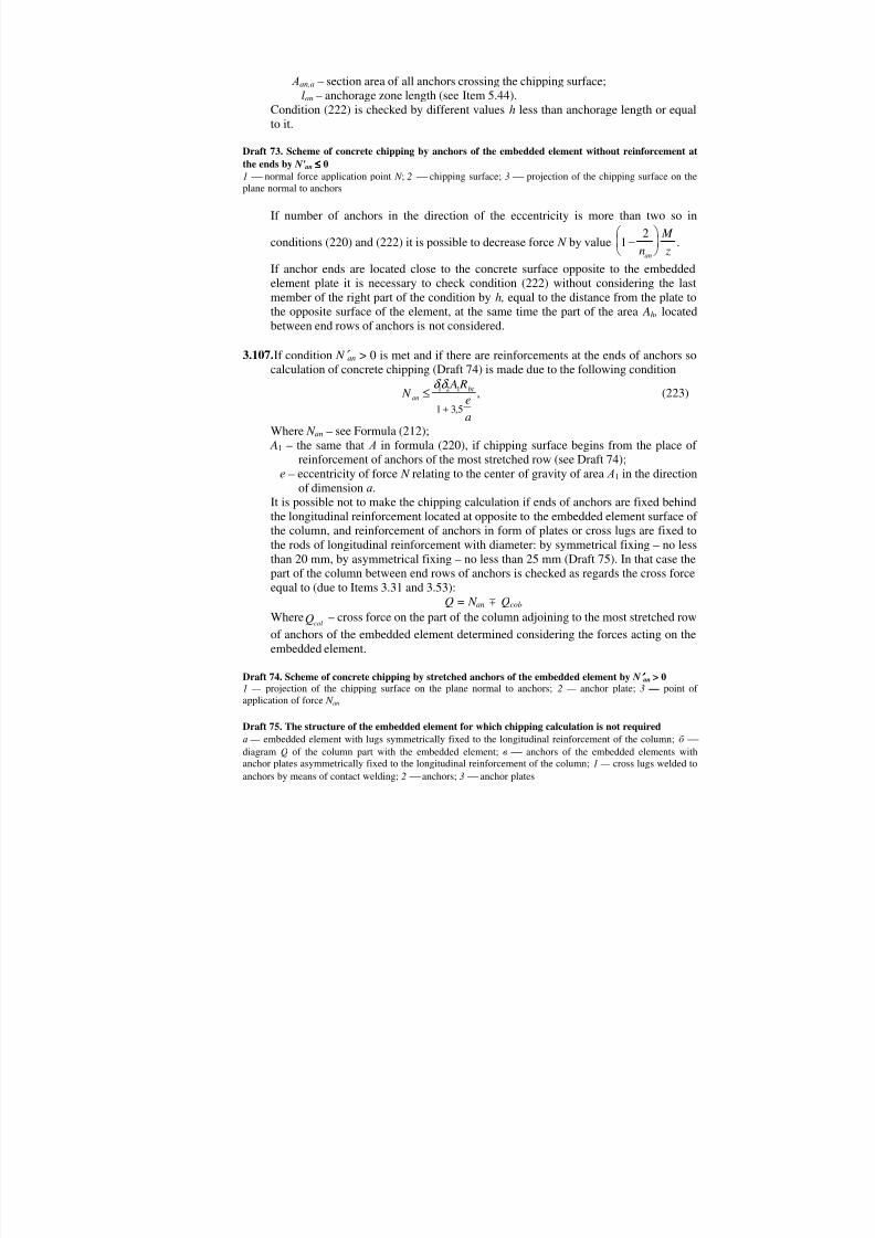
Draft 73. Scheme of concrete chipping by anchors of the embedded element without reinforcement atthe ends by N' an ≤≤≤≤ 01 normal force application point N ; 2 chipping surface;3 projection of the chipping surface on theplane normal to anchors
If number of anchors in the direction of the eccentricity is more than two so in
conditions (220) and (222) it is possible to decrease force N by value 12
−
n
M zan
.
If anchor ends are located close to the concrete surface opposite to the embeddedelement plate it is necessary to check condition (222) without considering the lastmember of the right part of the condition byh, equal to the distance from the plate tothe opposite surface of the element, at the same time the part of the area Ah , locatedbetween end rows of anchors is not considered.
3.107. If condition N ′ an > 0 is met and if there are reinforcements at the ends of anchors socalculation of concrete chipping (Draft 74) is made due to the following condition
N A R
ea
anbt ≤
+
δδ 1 2 1
1 3 5,, (223)
Where N an – see Formula (212); A1 – the same that А in formula (220), if chipping surface begins from the place of
reinforcement of anchors of the most stretched row (see Draft 74);е – eccentricity of force N relating to the center of gravity of area А1 in the direction
of dimensionа .It is possible not to make the chipping calculation if ends of anchors are fixed behindthe longitudinal reinforcement located at opposite to the embedded element surface ofthe column, and reinforcement of anchors in form of plates or cross lugs are fixed tothe rods of longitudinal reinforcement with diameter: by symmetrical fixing – no lessthan 20 mm, by asymmetrical fixing – no less than 25 mm (Draft 75). In that case thepart of the column between end rows of anchors is checked as regards the cross forceequal to (due to Items 3.31 and 3.53):
Q = N an m Q col ,Where colQ – cross force on the part of the column adjoining to the most stretched rowof anchors of the embedded element determined considering the forces acting on theembedded element.
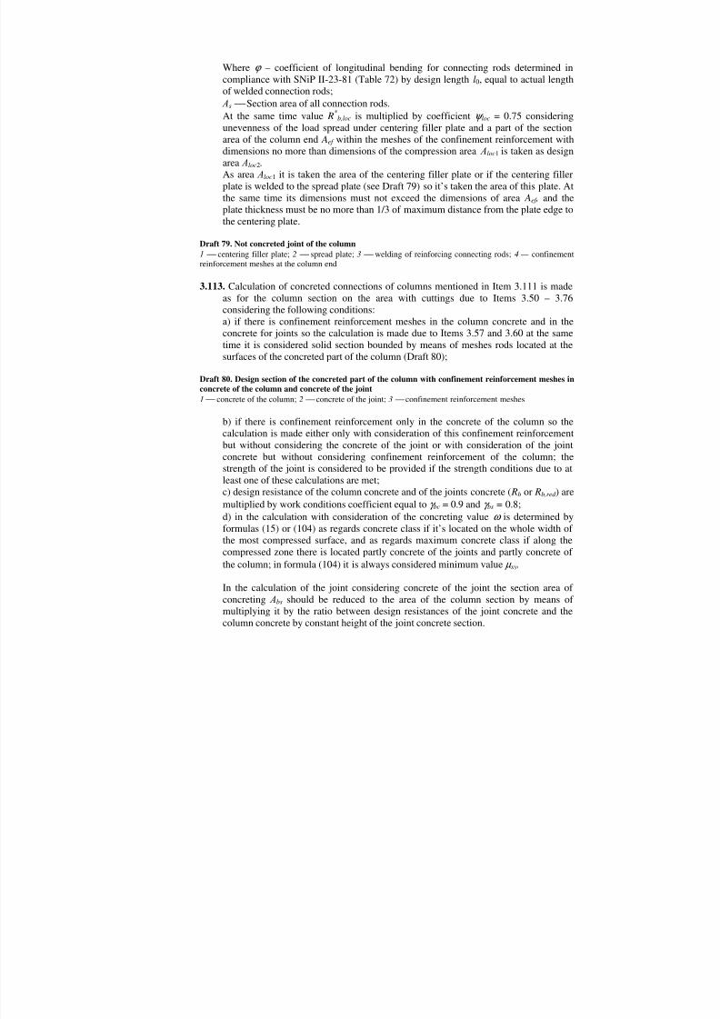
Draft 74. Scheme of concrete chipping by stretched anchors of the embedded element by N ′ ′′ ′ an > 01 — projection of the chipping surface on the plane normal to anchors;2 — anchor plate;3 — point ofapplication of force N an
Draft 75. The structure of the embedded element for which chipping calculation is not requiredа — embedded element with lugs symmetrically fixed to the longitudinal reinforcement of the column;б diagramQ of the column part with the embedded element;в anchors of the embedded elements with
anchor plates asymmetrically fixed to the longitudinal reinforcement of the column;1 — cross lugs welded toanchors by means of contact welding;2 anchors;3 anchor plates

8/10/2019 Guidelines for Design of Concrete and r.c.structures_part2.ENG
http://slidepdf.com/reader/full/guidelines-for-design-of-concrete-and-rcstructurespart2eng 3/111
3.108. If shearing forceQ acts on the embedded element in the direction towards the
element edge (Draft 76), and if there are no inclined anchors so calculation as regardsthe concrete chipping is made due to the following condition
Q
R bh
eb
bt
≤ +
δ 1
1 3 5, , (224)
Whereδ 1 – see Item 3.106; by embedded element located on the top surface of detailsmade of light-weight concrete coefficientδ 1 is decreased by 20 percent,
b – element width equal tob = c1 + c2 + s (где c1 и c1 – distances from endrows of anchors to the nearest edges of the element in the directionnormal to the shear force taken no more thanh, s – distances betweenend rows of anchors in the same direction);
h – the distance from the outermost anchor row to the edge of the element inthe direction of shearing forceQ, taken no more than the element width
b1 (see Draft 76);е – eccentricity of forceQ relating to the middle of the element widthb.
In case if break force N is applied to the embedded element except shearing forceQ
the right part of condition (224) is multiplied by the coefficientδ nout bt
N A R
= −10 3, , taken
no less than 0,2 (where Aout is the area of the projection on the plane perpendicularto the break force N, and to the chipping surface).
Draft 76. The scheme for the calculation of the concrete chipping by normal anchors of the embeddedelement
In case if shearing force is applied to the embedded element with inclined anchorswelded with overlapping and which have reinforcement at the ends (see Item 5.113),calculation of concrete chipping is made in compliance with the Recommendationsmentioned in Item 3.102.
3.109. If at the ends of anchors of the embedded element there are reinforcements in formof anchor plates (see Item 5.113) so concrete under these reinforcements are checkedas regards compression due to the following condition
N R Aloc b b loc≤ α 1, (225)
Whereα , b – coefficients determined due to Item 3.93; Аloc1 – area of concrete plate with the exception of the anchor section area; N loc – compression force determined in the following manner:
а) for anchors byla ≥ 15d:If crack formation along the anchor is possible as result of concrete tension or incase of use of plane anchor rods by formula
N loc = N an1 ; (226)If crack formation is impossible — by formula
N loc = N an1l l
lan a
an
− ; (227)

8/10/2019 Guidelines for Design of Concrete and r.c.structures_part2.ENG
http://slidepdf.com/reader/full/guidelines-for-design-of-concrete-and-rcstructurespart2eng 4/111
б) for anchors byla < 15d value N loc determined by formulas (226) and (227), is
decreased byQ d llan
a
an115 − ;
в) for anchors welded with overlapping N loc is determined by formula N loc = Q inc . (228)
In formulas (226) (228): N an1, Qan1 – maximum tension and shearing forces per one normal anchor (see Item
3.101);Q inc – force in the inclined anchor
Formula (225) can be used if thickness of anchor plate is less than 0.2 of its length.
3.110. Determination of welded embedded elements details, calculation of inclined anchorswelded under the flax material layer to the plate at the angle more than 45 degrees
and calculation of pressed embedded details is made according to Recommendationsmentioned in Item 3.102.
CALCULATION EXAMPLES
Example 50. Given: embedded element of the column with the welded table for support ofthe framing beam as well as location and values of loads and framing beams – due to Draft77; anchors of reinforcementА-III ( Rs = 365 MPa); heavy-weight concrete of the columnВ20; plate of steel gradeВСт 3кп2 ( R y = 215 MPa).
It is required to design normal anchors of the embedded element and to determine the platethickness.
Draft 77. For the calculation example 50
C a l c u l a t i o n . Let’s take location of anchors as it’s shown on Draft 77. As all loads actin one direction and don’t cause the torsion, so let’s determine total area of the anchorscross section of the most compressed upper row by formula (211).For that we determine external forces moment:
М = Ql = 150 0,15 = 22,5 kNmTaking z = 0,3м and N = 0, let’s determine maximum tension force in one anchor row byformula (212):
N M zan = = =
22 50 3 75
,, кН .
On Draft 77 shearing force isQ = 150 kN, anchor rows number isnan = 3.Shearing force per one anchor row is to be determined by formula (213), taking N ′ an = N an = =75 kN:
QQ N
nanan
an
= ′−
=−
=0 3 150 0 3 75
342 5
, ,, кН .
Coefficientδ is to be determined by formula (216).
As N ′ an > 0,ω = 0,3 N Q
an
an
= =0 375
42 50529,
,, ,
So δ ω
=+
=+
= >111
1 0 5290 808 015
,, , .

8/10/2019 Guidelines for Design of Concrete and r.c.structures_part2.ENG
http://slidepdf.com/reader/full/guidelines-for-design-of-concrete-and-rcstructurespart2eng 5/111
Taking diameter of anchors 16 mm according to Table 28 by concrete classВ20 andreinforcement classА-III we findλ = 0,43, so
.mm432365
808,043,042500
750001,12
22
221,1
=
+
=
+=
s
anan
an R
Q N
Aλδ
We take two anchors with diameter 18 mm in each row ( Aan = 509 mm2).Let’s check condition Aan by coefficient corresponding to the accepted diameter 18 mm,that means byλ = 0,41:
Aan =
+
= <
11 75000
425000 41 0 808
365448 509
22
,, ,
.мм мм2 2
We take 2 18.Let’s determine minimum allowable anchors length without forceslan due to Item 5.112.
For that we determine coefficientδ 3:δ 3
0 31
0 70 3
1 42 5 750 7 0 89=
+ + =
++ =
, / .,
,, /
, ,Q N an an
Value Rb is taken consideringγ b2 = 0,9 (no short-term loads), that means Rb = 10,5 MPa.Let’s determinelan , takingσ bc < 0,25 Rb, that meansω an = 0,7,∆λ an = 11:
l R
Rd an
an s
ban= +
= + =δ
ω λ 3 0 89 0 7
36510 5
11 18 567∆ , ,,
мм .
Considering the fact that area Aan is taken with the reserve let’s specify valuelan moreexact:
lan = =567448509 500мм > 400мм .
As location of anchors in the column by such length is impossible so it is necessary todecrease the length of anchors and reinforce their ends. Due to Item 5.113 anchor ends areto be reinforced by button-heads with diameterd h = 54 m ≥ 3d and concrete is to bechecked as regards compression and chipping taking anchors lengthla = 250 mm > 10d = 10 18 = 180 mm.Compression calculation is to be made due to Item 3.109.Compression area Аloc1 under a button-head of one anchor is:
22
111 mm203625445414,3
=−=−= anhloc A A A .
Let’s suppose that crack formation in the column on the side of the embedded element ispossible. So in compliance with Item 3.109 byla = 250 mm < 15d = 15 18 = 270 mmcompression force will be:
.15kN45
25,42
567250270
275
11 =−
+=−
+= anan
aanloc Q
l
ld N N
Let’s take maximum value b = 2.5 as design area of concrete Аloc2 here is large;α = 1.0.Let’s check condition (225):
,N450005345020365,105,211 == >= loclocbb N A R H α That means the strength as regards compression is provided.As N ′ an > 0 so chipping calculation is made according to Item 3.107. Anchor ends withreinforcement are not fixed to the longitudinal reinforcement of the column located at the

8/10/2019 Guidelines for Design of Concrete and r.c.structures_part2.ENG
http://slidepdf.com/reader/full/guidelines-for-design-of-concrete-and-rcstructurespart2eng 6/111
surface opposite to the embedded element of the column that’s why calculation is made dueto the condition (223).Let’s determine value A1 (see Draft 77):
A1 = (2 250 + 54) 400 - 23 14 544
2, = 217000 mm2.
Force N an = 75 kN is applied in the center of gravity of area А1, soе = 0. For heavy-weightconcreteδ 1 = 0.5.
Let’s check condition (223) without considering compression stress of concrete (that meansδ 2 = 1.0) and takingγ b2 = 0.9 (that means Rbt = 0.8 MPa):δ 1δ 2 A1 Rbt = 0.5 1 217000 0.80 = 86800 N > N an = 75000 N,That means concrete strength as regards chipping is provided.Accepted distances between anchors in the direction across and along the shearing forceequal to 260 mm > 5d = 5 18 = 90 mm and 150 mm > 7d = 7 18 = 126 mm meet therequirements of Item 5.111. The distance from the anchor axis to the column surface equal
to 70 mm > 3.5d = 3.5 18 = 63 mm also meet requirements of Item 5.111.Structure of the table welded to the embedded element provides even distribution of forceson the stretched anchors and even transfer of compression stressed on concrete withoutcausing bending of the embedded element plane. That’s why thickness of this plate is to bedetermined due to condition (218) taking Rsq = 0.58 R y = 0.58 215 = 125 MPa, and anchor
diameter required by the calculation isd an = 18448509 = 16.9 mm:
t = 0.25d R Ran
s
sq
= 0.25 16.9 365125
= 12.3 mm.
Due to conditions of mechanized arc welding under flux (see Table 52, position 1) platethickness must be no more than 0,65d = 0.65 18= 11.7 mm.We take the plate thicknesst = 14 mm.
Example 51. Given: embedded element of the column with welded diagonal member ofsteel bracings — according to Draft 78,а; tension force in the diagonal member caused bywind loads 270 kN; embedded element anchors of reinforcement A-III ( Rs = 365 MPa);embedded element plate of steelВСт 3сп2 ( R y = 215 MPa); heavy-weight concrete of thecolumnВ30; column reinforcement — due to draft 78,б , minimum longitudinal force inthe column 1100 kN; bending moment in the column at the level of the embedded elementin the plane of anchors 40 kN m.
It is required to design anchors of the embedded elements, to determine the plate thicknessand to check the strength of surrounding concrete as regards chipping.C a l c u l a t i o n . We take location of anchor rows along the vertical line as it’s shown onDraft 78,в. The force in the diagonal member is resolved into the normal force N, appliedto the embedded element with eccentricitye0 = 100 mm, and shearing forceQ:
N = 270 cos 56°20′ = 270 0,555 = 150 kN;Q = 270 sin 56°20′ = 270 0,832= 225 kN.
By z = 0.42 m and M = Ne 0 = 150 0.1 = 15 kNm let's determine maximum tension forcein one row of anchors by formula (212):
kN2,734
15042,0
15=+=+=
anan n
N
z
M N
Maximum compression force in row of anchors we determine by formula (214):

8/10/2019 Guidelines for Design of Concrete and r.c.structures_part2.ENG
http://slidepdf.com/reader/full/guidelines-for-design-of-concrete-and-rcstructurespart2eng 7/111
′ = − = − = − N M z
N nan
an
150 42
1504 18, , кН < 0,
Shearing forceQan , applied on one row of anchors is to be determined by formula (213), by N ′ an = 0:
QQnan
an= =
2254 = 56,25 kN.
As N' an = 0,
ω = 0,6 N Q
= 0,6150225 = 0 4,
so δ ω
=+
=+
11
11 0 4,
= 0,845 > 0,15.
Draft 78. For the example calculation 51
Due to Table 28, taking anchor diameter 16 mm by concrete classВ30 and anchors ofreinforcementА-III we findλ = 0,49,тогда
.mm465365
845,049,0562500732001,11,1
2
22
22
=
+=
+=
s
anan
an R
Q N
Aλδ
In each row we take two anchors with diameter 18 mm ( Aan = 509 mm2). Let’s checkrequired value Aan by coefficientλ , corresponding to the accepted diameter 18 mm, thatmeans byλ = 0,46:
.mm509mm448365
845,046,056250
732001,1 22
22
<=
+=an A
Let’s take two anchors with diameter 18 mm in each row. Let’s arrange the anchors withthe minimum direction between them in the horizontal direction equal to 5d = 5 18 = 90mm (see Item 5.111). Distances between anchors in the vertical direction (that means in thedirection of the shearing forceQ) are equal to 140 mm > 7d = 7 18 = 126 mm alsocorresponds to requirements of Item 5.111.Let’s determine the thickness of the embedded element plate. As the gusset plate whichtransfers the break force to the embedded element is located in the middle of the distancebetween vertical rows of anchors so the thickness of the plate is to be determined accordingto the calculation of the strength of the plate as of the console beam with the overhanginglength 35 mm (see Draft 78) as regards tension force in one anchor equal to:
N N
anan
1 2 73 2= = , = 36.6 kN.
The width of the console beam isb = 80 mm. Calculation is made due tot he condition
М ≤ R yW, where М = 36600 35 = 1280000 Nmm,W bt
=2
6 ,
thereforet M
R b y
= = 6 6 128 10
215 80
4
= 21.2 mm.
We take the plate made of strip steel 22 mm thick, at the same time condition (218) is met:

8/10/2019 Guidelines for Design of Concrete and r.c.structures_part2.ENG
http://slidepdf.com/reader/full/guidelines-for-design-of-concrete-and-rcstructurespart2eng 8/111
0,25 d R Ran
s
sq
= 0,25 18365130= 12,6 mm < 22 mm and requirements for any kind of T-joint
welding of rods (see Table 52): 0,75d = 0,75 18 = 13,5 mm < 22 mm.Let’s determine minimum allowable length of anchors without reinforcement by formula
(316) considering Item 5.112. For that we determine coefficientδ 3:δ 3
0 31 0 7 0 3
1 56 25 73 2 0 7 0 87=+
+ =+
+ =, / , ,
, / , , , .Q N an an
Value Rb is taken consideringγ b2 = 1.1 as the load on the embedded element is caused onlyby wind load, that means Rb = 19МПа .For determination of coefficientsω an and ∆λ we determine maximum and minimumconcrete stress within the anchor length. For that we determine area Ared and inertiamoment I red of the column section taking due to Draft 78,б Аs = А′ s = 1232 mm (2 28):
Аred = bh + 2 Аs (α - 1) = 400 400 + 2 1232 (6,9 - 1) = 174,5 103 mm2;
I red = bh3
12 + 2 Аs (α - 1)(0,5h - a )2 =
= 400 40012
3
+ 2 1232 (6,9 - 1) (0,5 400 - 50)2 = 2460 106 mm4
here a E E
s
b
= = 2 102 9 10
5
4, = 6,9.
Maximum concrete stress at the end of anchorla = 300 mm (that means at the distance у = 300 + 22 - 400/2 = 122 mm from the center of gravity of the section):
σ bred red
N
A
M y
I ,max
,= − =
+
1100 10
174 5 10
40 10 122
2460 10
3
3
6
6 =
= 6,31 + 1,98 = 8,3МПа < 0,75 Rb = 14,3 MPa.
Minimum stress of concrete at the beginning of concrete; that means by у =4002 - 22 =
178 mm:
σ bred red
N A
M y I ,min ,= − =
6 3140 10 1782460 10
6
6 = 3,42МПа < 0,25 Rb = 4,75 MPa.
As the anchor is not located in the zone with stress from 0.25 Rb до 0.757 Rb, so wedetermine the length of the part of the anchorа , located in this zone:
mm21842,33,875,43,8300
25,0min,max,
max, =−
−=
−
−=
bb
bb
a
Rla
σ σ
σ
So due to Formula (317),
ω ana
a
l a al
= − +
= − +
=0 7 0 5 0 7 300 218 0 5 218
300 0555, ( ) , , ( ) , , .
∆λ an is determined similar toω an with replacement coefficients 0.7 and 0.5 by 11 and 8 (seeTable 44):
∆λ ana
a
l a al
= − +
= − +
=11 8 11 300 218 8 218
300 8 82( ) ( ) , .
Allowable anchor length is:
mm.3051882,819365555,087,03 =
+=
∆+= d
R Rl an
b
sanan λ ω δ

8/10/2019 Guidelines for Design of Concrete and r.c.structures_part2.ENG
http://slidepdf.com/reader/full/guidelines-for-design-of-concrete-and-rcstructurespart2eng 9/111
Considering that area Aan is taken with the reserve we take thatlan : lan = 305488509
= 292мм .
We take anchor lengthla = 300 mm.Let’s check the chipping concrete.As all anchors are stretched and have no reinforcement so the calculation is made due tocondition (222). Let’s determine the projection area of the chipping surface Аh consideringdisplacement of the inclined surface by 2e0 = 2 100 = 200 mm. Byh = la = 300 mm
Ah = (420 - 200 + 2 300) 400= 32.8 104 mm2.As force N is applied in the center of gravity of area Ah , e h1 = еh2 = 0, δ 1 = 0,5 (as forheavy-weight concrete).By formula (221) we get
δ 2 = 1 + 0,2 ala
= 1 + 0,2218300
= 1.145.
As la = h, R s Аап ,а (la - h) / lan = 0. Considering that byγ b2 = 1.1, Rbt = 1,3 MPa.δ 1δ 2 Ah Rbt = 0,5 1,145 32,8 104 1,3 = 244300Н > N = 150 kN.
Let’s check condition (222) byh = 200 mm <la . As at the distanceh from the platechipping surface crosses only two pairs of anchors so
Aan1 = 1018мм2 (4 18); Аh = (420 - 200 + 2 200) 400 = 24,2 104 mm2,
δ 1δ 2 Ah Rbt + R s Аап ,аl h
la
an
− = 0,5 1,145 24,2 104 1,3 + 365 1018300 200300− =
= 304 103 Н > N = 150 kN.As after decreasing ofh concrete bearing capacity is increased so calculation by less valuesh is not required.Let’s check condition (222) by valueh, equal to the column section height; that meansh ==400 mm, without considering the area between anchors [(420 - 200) 90 = 19800 mm2]:
Аh = (420 - 200 + 2 400) 400 - 19800 = 388 000мм2 > 328000 mm2,That means Аh is more than the area determined byh = 300 mm. So, concrete strengthagainst chipping is provided.
CALCULATION OF PREFABRICATED COLUMNS JOINTS
3.111. Column joints made by means of welding of reinforcement connecting rods (seeItem 5.90) are calculated for two work stages:
1st stage – before concreting of the joint the calculation is made as regards the loadsacting during this construction phase; by determination of forces the joints areaccepted as hinged ones;
2nd – after concreting of the joint the calculation is made as regards the loads actingduring this construction phase and during use of the building; by determination offorces the joints are accepted as fixed ones.
3.112. Calculation of not concreted joints of the columns mentioned in Item 3.111 (Draft79) is made as regards local compression of the column concrete by means ofcentering filler plate due to condition (196) adding to its right part a part of force
acting on the reinforcement connecting rods and equal to: N out = 0.5 Rsc As (229)
8/10/2019 Guidelines for Design of Concrete and r.c.structures_part2.ENG
http://slidepdf.com/reader/full/guidelines-for-design-of-concrete-and-rcstructurespart2eng 10/111
Where – coefficient of longitudinal bending for connecting rods determined incompliance with SNiP II-23-81 (Table 72) by design lengthl0, equal to actual lengthof welded connection rods; Аs Section area of all connection rods.At the same time value R*
b,loc is multiplied by coefficientψ loc = 0.75 consideringunevenness of the load spread under centering filler plate and a part of the sectionarea of the column end Aef within the meshes of the confinement reinforcement withdimensions no more than dimensions of the compression area Аloc 1 is taken as designarea Аloc2.As area Аloc 1 it is taken the area of the centering filler plate or if the centering fillerplate is welded to the spread plate (see Draft 79) so it’s taken the area of this plate. Atthe same time its dimensions must not exceed the dimensions of area Aef , and theplate thickness must be no more than 1/3 of maximum distance from the plate edge tothe centering plate.
Draft 79. Not concreted joint of the column1 centering filler plate;2 spread plate;3 welding of reinforcing connecting rods;4 — confinementreinforcement meshes at the column end
3.113. Calculation of concreted connections of columns mentioned in Item 3.111 is madeas for the column section on the area with cuttings due to Items 3.50 – 3.76considering the following conditions:а) if there is confinement reinforcement meshes in the column concrete and in theconcrete for joints so the calculation is made due to Items 3.57 and 3.60 at the sametime it is considered solid section bounded by means of meshes rods located at thesurfaces of the concreted part of the column (Draft 80);
Draft 80. Design section of the concreted part of the column with confinement reinforcement meshes inconcrete of the column and concrete of the joint1 concrete of the column;2 concrete of the joint;3 confinement reinforcement meshes
b) if there is confinement reinforcement only in the concrete of the column so thecalculation is made either only with consideration of this confinement reinforcementbut without considering the concrete of the joint or with consideration of the jointconcrete but without considering confinement reinforcement of the column; thestrength of the joint is considered to be provided if the strength conditions due to atleast one of these calculations are met;c) design resistance of the column concrete and of the joints concrete ( Rb or Rb,red ) aremultiplied by work conditions coefficient equal toγ bc = 0.9 andγ bs = 0.8;d) in the calculation with consideration of the concreting valueω is determined byformulas (15) or (104) as regards concrete class if it’s located on the whole width ofthe most compressed surface, and as regards maximum concrete class if along thecompressed zone there is located partly concrete of the joints and partly concrete ofthe column; in formula (104) it is always considered minimum value µ xy.
In the calculation of the joint considering concrete of the joint the section area ofconcreting Аbs should be reduced to the area of the column section by means ofmultiplying it by the ratio between design resistances of the joint concrete and thecolumn concrete by constant height of the joint concrete section.
8/10/2019 Guidelines for Design of Concrete and r.c.structures_part2.ENG
http://slidepdf.com/reader/full/guidelines-for-design-of-concrete-and-rcstructurespart2eng 11/111
For symmetrically reinforced columns of rectangular section calculation of theconcreted joint can be made due to formulas of Items 3.67 and 3.68, taking forh′ f = h f the height of cutting sections, and forb′ f = b f – width of the section reduced toconcrete of the column, along the most compressed side of the section.
Coefficientη , considering deflection of the column (see Item 3.54), is determined dueto geometrical characteristics of the column section beyond the joint zone.
3.114. Joints of columns made by means of connection of ends by means of the cementlayer or polymer solution with break of longitudinal reinforcement (see Item 5.91, joints of the 1st and the 2nd type) at the use stage are calculated as eccentriccompressed concrete elements due to Item 3.6 considering confinement reinforcementby meshes due to Items 3.57 and 3.60. At the same time design resistance of concrete
Rb,red is multiplied by the work condition coefficientγ b, equal to 0.9 or 1.0 by fillingof the joint by cement or polymer solution. If there is no solution between the ends ofthe columns (for example in spherical joints, in joints with connected surfaces) thementioned above work condition coefficient is taken equal toγ b = 0,65.
CALCULATION EXAMPLESExample 52. Given: a column joint – due to Draft 81; concrete of the columnВ30( Rbc = 15,5 MPa byγ b2 = 0,9; Rb,ser = 22 MPa); concrete for joints B20(Rbs = 10,5 MPa byγ b2 = 0,9; Rb,ser = 15 MPa); reinforcement connecting rodsА-III ( Rs = R sc = 365 MPa;
Rs,ser = 390 MPa), their section area Аs = А' s = 4070 mm2 (4 36); confinementreinforcement meshes made of rodsА-III, with diameter 8 mm ( Rs,xy = 355 MPa) withspacings = 70 mm both in concrete of the column; longitudinal force during the use stage
N = 3900 kN by γ f > 1,0 and N = 3300 kN byγ f = 1.0, its eccentricity in the directionperpendicular to the cuttings considering the column bendinge0 = 55 mm. It is required to examine the strength of the joint during the use stage and to determinemaximum allowable longitudinal force in the joint during the construction stage.
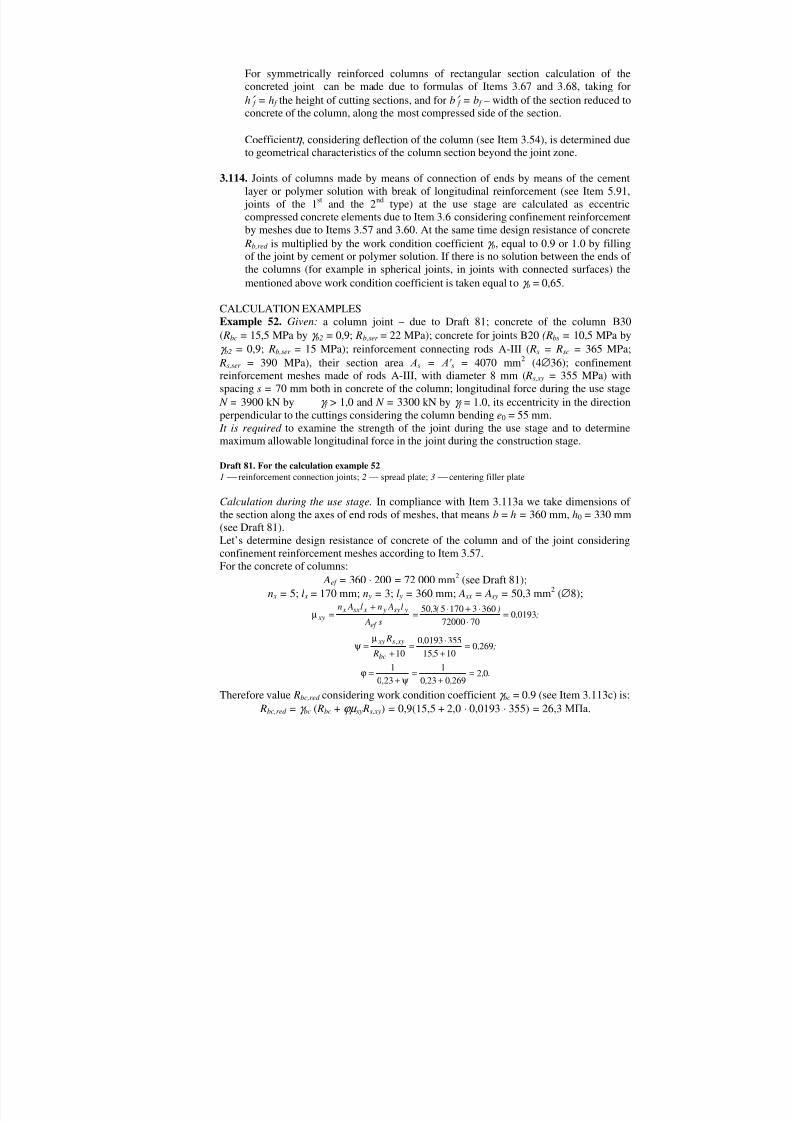
Draft 81. For the calculation example 521 reinforcement connection joints;2 — spread plate;3 centering filler plate
Calculation during the use stage. In compliance with Item 3.113a we take dimensions ofthe section along the axes of end rods of meshes, that meansb = h = 360 mm,h0 = 330 mm(see Draft 81).Let’s determine design resistance of concrete of the column and of the joint considering
confinement reinforcement meshes according to Item 3.57.For the concrete of columns: Aef = 360 200= 72 000 mm2 (see Draft 81);
n x = 5; l x = 170 mm;п y = 3; l y = 360 mm; Asx = A sy = 50,3 mm2 ( 8);
; ,)( ,
s A
l Anl An
ef
ysy y xsx x xy 01930
707200036031705350
=+
=+
=µ
; , ,
, R
R
bc
xy ,s xy 26901051535501930
10 =
+=
+
µ=ψ
. , , , ,
022690230
1230
1=
+=
ψ +=
Therefore value Rbc,red considering work condition coefficientγ bc = 0.9 (see Item 3.113c) is: Rbc,red = γ bc ( Rbc + µ ху Rs, ху) = 0,9(15,5 + 2,0 0,0193 355)= 26,3МПа .

8/10/2019 Guidelines for Design of Concrete and r.c.structures_part2.ENG
http://slidepdf.com/reader/full/guidelines-for-design-of-concrete-and-rcstructurespart2eng 12/111
For concrete of the joint in one of the cuttings Aef = 360 80 = 28 800мм 2 (см. черт . 81);
Asx = A sy = 50,3мм 2 ( 8); l x = 65мм ; l y = 360мм ;
µ xy x sx x y sy y
ef
n A l n A l
A s=
+=
+ =
50 3 5 65 3 36028800 70 0026, ( ) , ;
ψ µ
=+
=
+ = xy s xy
bs
R
R, ,
, , ;100026 35510 5 10 0450
ψ
=+
=+
=1
0 231
0 23 0 450 147, , , , .
Value Rbs,red considering work condition coefficientγ bs = 0.8 is: Rbs,red = γ bs ( Rbs + µ ху Rs, ху) = 0,8(10,5 + 1,47 0,026 355) = 19,3МПа .
Let’s determine valueω by formula (104) according to class of concrete of joints, as thecutting is located along the whole width of the most compressed surface of the column, atthe same time we take minimum value µ xy = 0.0193:δ 2 = 10 µ xy = 10 0.0193= 0.19 > 0.15, we takeδ 2 = 0.15;ω = 0.85 - 0,008 Rbs + δ 2 = 0.85 – 0.008 10.5 + 0.15 = 0.916 > 0.9, we takeω = 0.9.We reduce the section of the joint to the concrete of the column, at the same time the widthof the cutting is equal:
′ = =b b R
R f bs red
bc red
,
,
,,
36019 326 3
= 264 mm;
The height of the cuttingh′ f = 80 mm (see Item 81).The joint strength is to be checked according to Item 3.67.For that we determine valueξ R by formula (14) takingσ sc, и = 500 MPa:
ξ ω
σ ω R
s
sc и
R=+ −
=
+ −
=1 1 11
0 9
1365500
10 911
0794
, ,
,,,
, ;
Aov = (b' f - b ) h ′ f = (264 - 360)80= - 7680мм 2.The height of compressed zone is:
mm.80>mm4333603,26
76803,263103900 ,
,==
+=
−= f
red bc
ovred bch
b R
A R N x
As х = 433 mm >ξ R h o = 0,794 330 = 260 mm, so the height of compressed zone is to bedetermined by formula (132).For that we determine:
α ss s
bc red o
R A R bh
= =
=, ,
, ;365 407026 3 360 330
0475
α nbc red o
N R bh
= =
=, ,
, ;3900000
26 3 360 3301248
α ovov
o
Abh
= =−
= −7680
360 33000646, ;
ψ σ
ω csc и
s R=
−
=
−
=,
,,,
, ;1 11
500
365 10 911
7 53

8/10/2019 Guidelines for Design of Concrete and r.c.structures_part2.ENG
http://slidepdf.com/reader/full/guidelines-for-design-of-concrete-and-rcstructurespart2eng 13/111
α α α s c s ov n+ + −=
+ − −=2
0 475 7 53 0 475 0 0646 12482
137, , , , ,
, ;
]
mm.293)9,053,7475,037,137,1(330 2
2
22
=++−=
=+
−+++
−++−= ω ψ α
α α ψ α α α α ψ α α τ
csnovcssnovcss
oh x
Valueе is e = eo +h ao − ′
2 = 55 + 330 302− = 205 mm.
The joint strength is to be checked according to condition (131): Rbc,red bx (ho - x /2)+ R bc,red Aov (ho - h′ f /2) + Rsc A′ s (ho - a ′ ) == 26,3 360 293 (330 - 293/2) - 26,3 7680 (330 - 80/2) +
+ 365 4070 (330 - 30)= 896.1 106 H мм > Ne = 3900 0,205 = 800 kN m,That means the strength joint during the use stage is provided.
Let’s check crack resistance of the concreted part of the column according to Item 3.60по similar to the calculation of the joint strength during the use stage:ho = h - a = 400 - 50 = 350 mm;
ω = 0,85 - 0,006 Rbs,ser = 0,85 - 0,006 15 = 0,76;
′ = =b b R
R f bs red
bc red
,
,400
1522
= 273 mm;h′ f = 100 mm;
Aov = (b' f - b ) h ′ f = (273 - 400) 100 = -12700 mm2; Rs = Rsc = R s,ser = 390 MPa;
α ss s
bc red o
R A R bh
= =
=,
, ;390 4070
22 400 3500515
α nbc red o
N R bh
= =
=,
, ;330000022 400 350
107
091.0350400
127000
−=−
==bh
Aovovα ;
32.3
1.176.01390
400
1.11
, =
−=
−=
ω σ
ψ
s
uscc
R;
532.0
2
07.1091.0515.032.3515.0
2
=−−+
=−++ novacs α α α ψ α ;
=+
−++
+−++
−= ω ψ α α α α ψ α α α α ψ α
csnovscsnovscsh x
2
0 22
( ) 25476.032.3515.0532.0532.0350 2 =+++− mm;
2052
50350552
'00 =
−+=
−+=
ahee mm
Rbc,ser bx (ho - x /2)+ R bc,ser Aov (ho - h′ f /2) + Rsc A′ s (ho - a ′ ) == 22 400 254 (350 - 254/2) - 22 12700 (350 - 100/2) + 390 4070 (350 - 50) =
= 890,8 106 H мм > Ne = 3300 0,205 = 677 kNm.

8/10/2019 Guidelines for Design of Concrete and r.c.structures_part2.ENG
http://slidepdf.com/reader/full/guidelines-for-design-of-concrete-and-rcstructurespart2eng 14/111
Calculation of not concreted joint during the construction stage. Let’s determine designresistance of concrete against compression considering confinement reinforcement due tItems 3.93 and 3.112.
Area of a part of the column end section bounded by meshes contours is: Aef = 170 360= 61200 mm2.Area of the distribution plate is taken as the compression area as its thickness 20 mm is
more than 1/3 of the distance from the plate edge to the centering plate (50 1/3= 17 mm),at the same time the width of the compression area is taken equal to the width of the mesh170 mm.
Aloc1 = 200 170 = 34 000 mm2.As 360 mm < 3 200 mm, we take Aloc 2 = Aef = 61200 mm2,Therefore:
5.322.13400061200
33
1
2 <===loc
locb A
A ;
56.261200340005.35.45.35.4 1 =−=−=
ef
locs A
A ;
( ) 0226.07061200
360317053.50=
+=
+=
s A
l Anl An
ef
ysy y xsx x xy µ
As the calculation is made as regards the loads during the construction stage so we take Rbc = 19 MPa (that meansγ b2 = 1.1):
277.010193550226.0
10, =
+=
+=
bc
xys xy
R
R µ ψ ;
97.1277.023.01
23.01
=+=++= ψ .
Value R*b,loc is determined by formula (197) considering coefficientψ loc = 0,75:
R*b,loc = ψ loc ( Rbс b + µ xy Rs,xy s) = 0,75 (19 1,22 +
+ 1,97 0,0226 355 2,56)= 47,7 MPa.By formula (229) we determine the force in reinforcement connecting rods.Radius of inertia of reinforcement rod36 is:
436
4 ==
d i = 9 мм .
Welded connection rods length isl = l
o =
400мм .Due to table 72 of SNiP II-23-81 byλ =
il0 =
9400
= 44,4 and R y = R s = 365МPа we find
= 0,838, therefore N out = 0,5 Rs Аs = 0,5 0,838× 365 8140 = 1245 103 N.
Maximum longitudinal force acting on the not concreted joint is: N = R*
b,loc Aloc1 + N оut = 47,7 34000 + 1245 103 = 2867 103 N
CALCULATION OF CONCRETE KEYS
3.115. Dimensions of concrete keys which transfer shearing forces between a prefabricatedelement and additional concrete (Draft 82), should be determined by formulas:

8/10/2019 Guidelines for Design of Concrete and r.c.structures_part2.ENG
http://slidepdf.com/reader/full/guidelines-for-design-of-concrete-and-rcstructurespart2eng 15/111
k k b
k nl RQ
t ≥ (230)
k k bt k nl R
Qh
2≥ (231)
WhereQ – shearing force transferred by concrete keys;t k , h k , lk – depth, height and length of the concrete key;пk – number of concrete keys inserted into the calculation and taken no more
than tree.
Draft 82. Scheme for the calculation of concrete keys transferring shearing force from theprefabricated element to monolithic concrete1 prefabricated element; 2 monolith concrete
By compression force N it is possible to determine the height of concrete keys by formula
k k bt k
nl R
N Qh
2
7.0−= (231)
and to take it decreased in comparison with the height determined by formula (231), but nmore than one half as much.
If deck elements are connected by means of concrete keys so the length of keys insertedinto the calculation must be no more than a half of a span, at the same time valueQ is takenequal to the sum of shearing forces along the whole length of the element.Due to conditions (230) – (232) it is necessary to check the keys of a reinforced concreteelement and keys of additional concrete, taking design resistance of concrete keys Rb and
Rbt as for concrete structures.
Note. By the calculation of a stretched leg of a two-leg column as regards the pulling out of a column pocketit is possible to take into account five keys.
4. CALCULATION OF CONCRETE AND REINFORCED CONCRETEELEMENTS AS REGARDS LIMIT STATES OF THE SECOND GROUP
CALCULATION OF CRACK FORMATION OF REINFORCED CONCRETEELEMENTS
4.1.(4.1). It is necessary to calculate crack formation of reinforced concrete elements asregards crack formation:
- Normal to the longitudinal axis of the element;- Inclined to the longitudinal axis of the element.
Calculation of crack formation is made:a) to find out if it is necessary to calculate the crack growth;b) to determine the deformation calculation case.
In the reinforced element or its part there is no cracks if forces caused by total load (oits part when load cause forces with different signs) and inserted into the calculationwith safety factorγ f = 1.0, are less than forces acting on the section during crack
formation. Total load include dead loads, long-term and short-term loads.

8/10/2019 Guidelines for Design of Concrete and r.c.structures_part2.ENG
http://slidepdf.com/reader/full/guidelines-for-design-of-concrete-and-rcstructurespart2eng 16/111
It is possible to take without calculation that bending moments of rectangular and T-sections with compressed flanges have normal to the longitudinal axis cracks on themost compressed parts if required by the calculation reinforcement coefficient µ > 0,005.
4.2.(4.5). Calculation of reinforced concrete elementsэлементов as regards formation ofnormal cracks is made due to the following condition М r < М crc , (233)
where М r – moment of external forces, located on one side on the considered section,relating to the axis which is parallel to zero line and which goes throughthe heart point, most distant from the stretched zone where crackformation is checked;
М crc – moment acting on the section normal to the longitudinal axis of the elementduring crack formation and determined by formula
M crc = R bt,ser W pl M shr , (234)here M shr – moment of force N shr caused by concrete settlement relating to the same
axis like for determination of М r ; sign of the moment is determined byspinning direction ("plus" – if directions are opposed, "minus" – if directionof moments М shr and М r are the same).
For free supported beans and slabs moment М crc is determined by formula M crc = R bt,ser W pl - N shr (eo p + r ). (235)
Force N shr is considered as external tension force; its value and eccentricity relating tothe center of gravity of the section are determined by formulas:
N shr = σ shr ( As + A ′ s); (236)
'
''
0ss
ssss p A A
y A y Ae−−= , (237)
whereσ shr – stress caused by concrete settlement equal to: 40 MPa – for heavy-weightconcreteВ35 and less by natural hardening and 35 MPa – by heat treating;for other kinds and classes of concrete valueσ shr is taken due to SNiP2.03.01-84 (Table5, position 8);
уs , у′ s – distance from the center of gravity of the section to the centers if gravity ofsections of reinforcementS andS ′ .
If reinforcement coefficient µ < 0.01 is possible in formulas (234) and (235) so valuesW pl andr are to be determined as for concrete section taking N shr = 0 and As = A' s = 0.Value M r is determined by formulas:
- For bending element(Draft 83,а) М r = М ;
- For eccentric compressed element (Draft 83,б ) M r = N (eo - r ), (238)
- For centrally- and eccentricэлементов (черт . 83,в) M r = N (eo + r ), (239)
In formulas (234), (235), (238) and (239):
r – the distance from the center of gravity of the section to the heart point which ismost distant from the stretched zone whose crack formation is checked.

8/10/2019 Guidelines for Design of Concrete and r.c.structures_part2.ENG
http://slidepdf.com/reader/full/guidelines-for-design-of-concrete-and-rcstructurespart2eng 17/111
Value r is determined by formulas:- For bending elements – by formula
red
red
A
W r = ; (240)
- For eccentric compressed elements – by formula
red
red
A
W r = (241)
hereser b
b
R ,6.1 σ
−=
but it’s taken no less than 0,7 and no more than 1,0;σ b – maximum stress in compressed concrete, determined as for elastic body
- For centrally- and eccentric stretched elements – by formula
( )'2 ss
pl
A A A
W r
++=
α , (242)
W pl – resistance moment of the transformed section for end stretched fibre consideringnon-elastic deformations of stretched concrete determined according to Item4.3.
N o t e . Transformed section includes concrete section as well as section of all longitudinal reinforcementmultiplied by the ratio between correspondent modulus of elasticity of reinforcement and concrete.
4.3.(4.7). Resistance moment of the transformed sections for end stretched fibreW pl (considering non-elastic deformations of stretched reinforcement) is determined withthe assumption that there is no longitudinal force N by formula
( ) 0
'
0002 bssb pl S xh I I I W +− ++= α α , (243)where I bo, I so, I ′ so – inertia moments of sections areas of compressed concrete zone,
reinforcementS andS ′ relating to the zero line;S bo – static moment of the section area of stretched concrete zone relating to the
zero line.
Location of the zero line in the general case is determine due to the following condition( )
20'0
'0
bt ssb
A xhS S S
−=−+ α α ,
(244)whereS ′ bo, S so, S ′ so – static moments of the section area of the compressed concretezone, reinforcementS andS ′ relating to the zero line;
Abt – section area of stretched concrete zone.
For rectangular sections, I- and T-sections condition (244) has the following form:
red
red
AS
xh =− (245)
where red S – static moment of the area of transformed section calculated withoutconsidering the area of stretched overhangs relating to the end stretched
fibre;

8/10/2019 Guidelines for Design of Concrete and r.c.structures_part2.ENG
http://slidepdf.com/reader/full/guidelines-for-design-of-concrete-and-rcstructurespart2eng 18/111

8/10/2019 Guidelines for Design of Concrete and r.c.structures_part2.ENG
http://slidepdf.com/reader/full/guidelines-for-design-of-concrete-and-rcstructurespart2eng 19/111
h′ f /h = h f /h < 0,25. I-section, asymmetricalmeeting the requirementb′ f /b ≤ 3:а) by b f /b ≤ 2 independentlyon the ratioh f /h
b) by 2 < b f /b ≤ 6independently on the ratioh f /hc) byb f /b > 6 andh f /h > 0,1
1,75
1,50
1,506. I-section, asymmetricalmeeting the requirement3 <b ′ f / b < 8: a) byb′ f /b ≤ 4 independentlyon the ratioh f /hb) byb f /b > 4 andh f / h ≥ 0,2c) byb f /b > 4 andh f / h < 0,2
1,50
1,501,25
7. I-section, asymmetrical
meeting the requirementb′ f / b ≥ 8:а) byh f /h > 0,3б) byh f /h ≤ 0,3
1,501,25
8. Ring- and round section 2-0,4 D 1 / D
9. X-section:а) by b′ f /b ≥ 2 and0,9 ≥ h′ f /h > 0,2б) in other cases
2,00
1,75
N o t e s : 1. In Table 29 symbolsb f and h f correspond to dimensions of a flange which is stretched by the crackformation calculation, andb′ f and h ′ f – dimensions of a flange which is compressed for that case.
2. W pl = γ W red , whereW red – resistance moment for the stretched surface of the transformed section determinedaccording to rules of resistance of elastic materials.
4.4. The parts along the elements where there are no inclined cracks are determinedaccording to the following condition
Q ≤ b3 Rbt.ser bh o , (248)Where b3 – see Table 21.
CALCULATION OF REINFORCED CONCRETE ELEMENTS AS REGARDS THECRACK FORMATION
4.5. (4.13) . Reinforced concrete elements are calculated as regards formation of cracks:- Normal to the longitudinal axis of the element;- Inclined to the longitudinal axis of the element.
Examination of the width of the crack opening is not required if according to thecalculation due to Items 4.1 – 4.4 they are not caused by dead loads, long-term loadsand short-term loads inserted into the calculation with the safety factorγ f = 1.0.
For bending and eccentric compressed elements of statically undeterminable systemsby one-row reinforcement mentioned in Table 1, position 4, it is not necessary to check
the width of the opening of normal cracks in the following cases:
8/10/2019 Guidelines for Design of Concrete and r.c.structures_part2.ENG
http://slidepdf.com/reader/full/guidelines-for-design-of-concrete-and-rcstructurespart2eng 20/111
а) for reinforcementА-I andА-II:by any reinforcement coefficient µ , if diameterd ≤ 20 mm;by µ ≥ 0,01, if diameterd = 22 – 40 mm;
б) for reinforcementА-III:by any reinforcement coefficient µ , if diameterd ≤ 8 mm;by µ ≥ 0,01, if diameterd = 10 — 25мм ;by µ ≥ 0,015, if diameterd = 28 40мм ;
в) for reinforcementВр-1 – by µ ≥ 0,006 by any diameters.
By calculation of crack formation the force caused by concrete settlement N shr is takenequal to zero.
4.6. In the general case calculation of crack opening is made two times: short-term and
long-term crack opening (see Item 1.15).For elements mentioned in Table 1 position 4 and made of heavy-weight and light-weight concrete it is possible to make only one calculation during examination ofopening of cracks normal to the longitudinal axis of the element:
If32
≥r
rl
M
M so long-term crack formation is checked;
If32
<r
rl
M
M so short-term crack formation is checked,
here M rl , M r – is moment M r (see Item 4.2) caused by the sum of dead loads and long-
term loads and by all loads.Calculation of crack opening of normal to the longitudinal axis of the elementcracks
4.7(4.14) . The width of the crack opening of normal to the longitudinal axis of the elementcracks,a crc mm, must be determined by formula
( )31005.320 d a E
as
slcrc −=
σ η δ
(249)
where δ – coefficient taken equal to:1.0............. for bending and eccentric compressed elements1.2............................................ for stretched elements;
l – coefficient taken equal to:1.00 ............. when considering short-term loads and dead loads and long-term loads ofshort duration;
when considering loads of long duration and dead loads and long-term loads forstructures made of:heavy-weight concrete:natural humidity...................... µ 1560.1
−=l

8/10/2019 Guidelines for Design of Concrete and r.c.structures_part2.ENG
http://slidepdf.com/reader/full/guidelines-for-design-of-concrete-and-rcstructurespart2eng 21/111
In water saturated state (elements taking liquids pressure, as well as elements used inthe ground below ground waters level) ...............................................1,20By changing water saturation and drying ...…………………….. 1,75Fine concrete of groups:А .................................................................................1,75Б ................................................................................. 2,00В ................................................................................. 1,50Light-weight concrete of classВ12.5 and more ..................................... 1.50Porous concrete ............................................................ 2.00
Values l for fine, light-weight and porous concrete in water saturated state aremultiplied by coefficient 0.8, and by changing water saturation and drying – bycoefficient 1.2;
η – coefficient taken equal to: for reinforcementА-II andА-III – 1.0;А-I – 1.3;Вр-1 –1.2;
σ s – stress in the rods of end row of reinforcementS, determined according to Item 4.9; µ – coefficient of the section reinforcement taken equal to the ratio between thereinforcement sectionS to the concrete section area (by working heightho and withoutconsidering compressed overhangs of flanges), but no more than 0.02, at the same timefor I-sections, rectangular and T-sections
( )( ) 02.00
≤−−+
=ahbbbh
A
f f
s µ
(250)if h f < а , so stretched overhangs are not considered during calculation;
if in eccentric stretched elements force N is located between centers of gravity ofreinforcementS and S ′ , by determination of µ working heightho is taken from thepoint of application of force N to the least stretched surface, at the same time for thecentral stretching µ where As,tot – is the area of all longitudinal reinforcement;
d – diameter of stretched reinforcement, mm; by different diameters of rods valued istaken equal to:
k k
k k
d nd nd nd n
d ++++
=......
11
2211
(251)
hered 1, ...,d k – diameter of rods of stretched reinforcement;п1, ...,nk – quantity of rods with diameterd 1, ..., d k ..
Besides it is necessary to consider instructions of Item 4.8.
4.8 (4.14) . Width of the crack openingа сrc , determined due to Item 4.7 is to be revised inthe following cases:
а) if center of gravity of the section of the end row of reinforcementS of bending,eccentric compressed, eccentric stretched byeо ≥ 0,8ho elements is distant from themost stretched fibre of concrete ata 2 > 0,2h, value a crc must be increased bymultiplying it by coefficientδ a, which is:
8/10/2019 Guidelines for Design of Concrete and r.c.structures_part2.ENG
http://slidepdf.com/reader/full/guidelines-for-design-of-concrete-and-rcstructurespart2eng 22/111

8/10/2019 Guidelines for Design of Concrete and r.c.structures_part2.ENG
http://slidepdf.com/reader/full/guidelines-for-design-of-concrete-and-rcstructurespart2eng 23/111
but no less than 0.8 and no more than 1.0,whereF – absolute value of the point load or of the support reaction;
М – absolute value of bending moment in the normal section going through thepoint of application of the point load and of the support reaction (Draft 84);
а – the distance from the point of application of the point load or of the supportreaction to the considered section taken in compliance with the Draft 84, butno more than 0,3h;
h – distance from the surface of the element at which it is applied forceF to thestretched surface;
ho – the same to the stretched reinforcement (Draft 85);
d) for elements made of light-weight concreteВ7,5 and less valuea crc must beincreased by 20 percent.
Draft 84. Location of support reactions in fixed joints taken for determination of the coefficient loc а - г prefabricated elements joints;д - и monolithic parts
Draft 85. Design schemes for determination of coefficient loc а application of load to the compressed surface of the element;б the same to the flanges of the element;в the same along the length of the statically undeterminable beam
4.9 (4.15). Stresses in the stretched reinforcementσ s are determined by the followingformulas:– for eccentric stretched elements
ss A
N =σ (258)
– for bending elements
ss A
N =σ ; (259)
– in eccentric compressed and eccentric stretched elements
z A
ze N
ss
±=σ (260)
In formula (260) sign «plus» is taken by eccentric stretching, sign «minus» – byeccentric compression. By location of stretching longitudinal force N between centersof gravity of reinforcementS andS ′ valueеs is taken with the sign «minus».
In formulas (259) and (260):z – distance from the center of gravity of the section area of reinforcementS to thepoint of application of the resultant of forces in the compressed zone of thesection above the crack determined due to Item 4.16, at the same time foreccentric stretched elements byео < 0,8ho z is taken equal to zs – distance betweencenters of gravity of reinforcementS and S ′ , coefficientv in formula (277) isalways taken equal to vsh = 0.45 (as by short duration of the load); it ispossible to take z the same like by calculation of deformation caused by the same
loads if 01.00
<bh
As .
In case when M r < M crc (see Item 4.2), valueσ s, is determined by formula

8/10/2019 Guidelines for Design of Concrete and r.c.structures_part2.ENG
http://slidepdf.com/reader/full/guidelines-for-design-of-concrete-and-rcstructurespart2eng 24/111
crc
r crcss M
M ,σ σ = (261)
whereσ s,crc – stress in reinforcement by action of the load corresponding to the crackformation determined by formulas (259) and (260) replacing М by M crc and N by
r
crccrc M
M N N = .
By determination of N crc moments M crc and M r can be calculated byr = 0,8W red /Ared .
By location of the stretched reinforcement in several rows along the section height inbending, eccentric compressed and eccentric stretched elements byeo > 0,8ho stressesσ s must be multiplied by the coefficientδ n, equal to:
1
2
a xha xh
n −−−−
=δ (262)
where х = ξ ho; valueξ is determined by formula (274); for bending elements it ispossible to take value х the same like by calculation of the strengthcalculation;
а1, a 2 — distance from the center of gravity of total reinforcementS and of the end rowof rods to the most stretched fibre of concrete.
Value of stressσ s caused by the total load determined considering coefficientδ n, mustbe no more than Rs,ser . It is not necessary to check this condition for staticallyundeterminable structures with reinforcement of one class by its location in one row.
Simplified way of determination of σ s. For bending moments it is possible todetermineσ s by the following formula:
uss M
M R=σ (263)
where М и – limit moment of the strength equal to:- By determination of the section strength – equal to the right part of equations
(17) – (21), (28), (30)- By choosing of the reinforcement section
sd
fact sd tot u A
A M M ,
,=
here M tot,d – moment caused by total load with the safety factor as regards the load
γ f > 1.0; Аs,fact – actual area of accepted reinforcement; Asd – area of reinforcement required by the strength calculation.
By using of reinforcement of different classed it is necessary to insert design resistanceof reinforcement for limit states of the second group Rs for the most hard reinforcementin formula (263).
For eccentric compressed elements of heavy-weight and light-weight concrete by M r ≥ M crc it is possible to useσ s by formula
crcs
ss h A
Ne σ 0= (264)

8/10/2019 Guidelines for Design of Concrete and r.c.structures_part2.ENG
http://slidepdf.com/reader/full/guidelines-for-design-of-concrete-and-rcstructurespart2eng 25/111
where crc – coefficient determined due to Table 30.
Ta bl e 30
f
0h
e s Coefficients crc by values µα , equal to
0,01 0,02 0,03 0,05 0,07 0,10 0,15 0,20 0,25 0,30 0,40 0,50
0
≤0,81,01,21,52,03,04,0
0,040,180,310,440,590,740,81
0,070,220,340,480,620,770,84
0,100,250,370,500,640,790,86
0,150,290,400,530,670,820,89
0,180,310,430,560,700,840,91
0,220,340,460,580,720,860,94
0,260,380,490,620,750,890,97
0,310,420,550,650,780,921,00
0,340,450,550,670,810,951,02
0,370,470,570,690,820,961,03
0,410,500,600,720,850,991,06
0,450,520,620,740,871,011,08
0,05
≤0,81,01,21,52,03,04,0
0,040,170,300,440,590,740,82
0,040,200,330,460,610,760,84
0,070,220,350,480,630,780,85
0,110,260,380,510,650,800,86
0,140,280,400,530,670,820,90
0,180,310,430,560,700,840,92
0,220,340,460,590,720,870,94
0,260,380,490,610,750,890,97
0,290,400,510,640,770,910,99
0,320,420,530,660,790,931,00
0,360,460,560,680,820,951,03
0,380,480,580,700,830,971,04
0,10
≤0,81,01,21,52,03,04,0
0,030,160,300,440,590,750,83
0,040,190,320,460,610,760,84
0,050,210,330,470,620,770,85
0,090,240,360,500,640,790,87
0,110,260,380,520,660,810,88
0,140,280,400,540,680,830,90
0,160,310,430,560,700,850,92
0,220,340,460,590,730,870,94
0,250,370,480,610,750,890,96
0,280,390,500,630,760,900,98
0,310,420,530,650,790,931,00
0,340,440,550,670,800,941,02
0,20
≤0,81,01,21,52,03,04,0
0,030,150,290,440,590,750,83
0,040,170,310,450,600,760,84
0,050,190,320,460,610,770,85
0,060,210,340,480,630,780,86
0,070,230,350,490,640,790,87
0,100,250,370,510,650,810,88
0,130,270,400,530,670,820,90
0,160,300,420,550,690,840,91
0,190,320,440,570,710,850,93
0,210,340,450,580,720,870,94
0,250,370,480,610,750,890,96
0,280,390,500,630,760,900,98
0,30
≤0,81,01,21,52,03,04,0
0,030,150,290,440,590,750,84
0,040,160,300,450,600,760,85
0,050,170,310,460,610,770,85
0,050,190,330,470,620,780,86
0,060,210,340,480,630,780,86
0,070,230,350,490,640,790,87
0,100,250,370,510,660,810,89
0,120,270,390,530,670,820,90
0,150,290,410,540,680,830,91
0,170,300,420,550,700,840,92
0,200,330,450,580,720,860,94
0,230,350,460,590,730,880,95
0,50
≤0,8
1,01,21,52,03,04,0
0,04
0,150,290,440,600,770,85
0,04
0,160,300,450,610,770,85
0,04
0,160,300,450,610,770,85
0,04
0,180,310,460,620,770,86
0,04
0,190,320,470,620,780,86
0,04
0,200,330,480,630,790,87
0,06
0,220,350,490,640,790,87
0,08
0,230,360,500,650,800,88
0,10
0,240,370,510,660,810,89
0,12
0,260,380,520,670,820,89
0,15
0,280,400,540,680,830,91
0,17
0,300,420,550,690,840,92
0,70
≤0,81,01,21,52,03,04,0
0,040,150,290,450,610,770,85
0,040,150,300,450,610,770,85
0,040,160,300,450,610,770,85
0,040,170,310,460,610,770,86
0,040,180,320,460,620,780,86
0,040,190,320,470,620,780,86
0,040,200,340,480,630,790,87
0,060,210,340,490,640,790,87
0,070,220,350,490,640,800,88
0,080,230,360,500,650,800,88
0,110,250,380,520,660,810,89
0,130,270,390,530,670,820,90

8/10/2019 Guidelines for Design of Concrete and r.c.structures_part2.ENG
http://slidepdf.com/reader/full/guidelines-for-design-of-concrete-and-rcstructurespart2eng 26/111
( )0
'''
9.0bh
Ahbb s
f f
f
α
+−
= ; N M
ye ss += ;b
ss
E
E
bh
A
0= µα
Calculated by formulas (263) and (264) valuesσ s in case when reinforcement is locatedin several rows along the section height are multiplied by the coefficientδ n.
4.10 (4.14). The width of crack opening caused by all loads is determined as a sum of thewidth of crack opening caused by dead loads and long-term loads (by l > 1.0) andexpansion of the width of the opening caused by short-term loads (by l = 1.0). So thewidth of the opening is determined by the following formula
−+=
lsl
slcrccrc aa
σ σ 111,
(265)wherea cr с ,l – the width of crack opening caused by dead loads and long-term loads;
l > 1,0 – see Item 4.7; if valuea cr с ,l is determined considering formula (253), socoefficient l in formula (265) is replaced by the product l l1 (where l1
– see Item 4.8б );σ sl, σ s – are determined due to Item 4.9, caused by the sum of dad loads and long-term loads as well as by all loads.
Calculation of opening of cracks inclined to the longitudinal axis of the element
4.11(4.17). The width of the crack opening inclined to the longitudinal axis of the elementby reinforcement by means of stirrups which are normal to the longitudinal axis mustbe determined by the following formula
( )wbw
s
wcwlcrc
E hd
E
d a
αµ
η σ
2115.0
06
0++
=
(266)where l – coefficient taken equal to:
considering short-term loads and dead loads and long term loads of short duration........ 1,00considering dead loads and long term loads of long duration for structures made of:heavy-weight concrete:by natural humidity............................................................................................................ 1,50
in water saturated state...................................................................................................... 1,20by changing water saturation and drying……………………………………………...… 1,75fine and light-weight concrete – the same like in formula (249);
η – the same like in formula (249);d w – diameter of stirrups;
bs Asw
w = µ ;
σ sw – stress in stirrups determined by the following formula
0
1
h A
sw
bsw
−=σ ; (267)
stressσ sw must be no more than Rs,ser ;

8/10/2019 Guidelines for Design of Concrete and r.c.structures_part2.ENG
http://slidepdf.com/reader/full/guidelines-for-design-of-concrete-and-rcstructurespart2eng 27/111
Qb1 – the right part of condition (72) with the coefficient b4, multiplied by 0.8, atthe same time Rbt is replaced by Rbt,ser , taken no more than the valuecorresponding to concrete classВ30;
Q – shear force at the end of inclined section with the projection lengthс.
Value с is taken no more than 2hо. If by the calculation of the element as regarddistributed load the following condition is metb Rq ser bt b ,41 2.0 ≤ (268)
(whereq1 – see Item 3.32), so valueс can be taken equal to only 2hо.
For elements made of light-weight concreteВ7.5 and lower valuea crc , determined byformula (266), must be increased by 30 percent.
By determination of the width of inclined cracks caused by all loads it is necessary toconsider instructions of Item 4.10. At the same time in formula (265) coefficient l is
taken according to the present Item and the ratioσ sl / σ s is replaced by the ration betweenthe stressesσ swl / σ sw , which are calculated by formula (267) of the sum of dead loadsand long-term loads and all loads.
It is possible to decrease valueа сrc by 1.5 times in comparison with the valuedetermined by formula (266), if the element is reinforced by means of longitudinal rodwith the same diameter like diameter of stirrups and with the distances along thesection height equal to the stirrups spacings.
EXAMPLES OF CALCULATION
Example 53 . Given: a reinforced concrete floor slab with the cross section dimensions (fora half of the slab section) due to Draft 86: b = 85 mm,h = 400 mm,b′ f = 725 mm,h′ f = 50mm; heavy-weight concreteВ25; main reinforcement A-III(Rs = 365 MPa; Е s = 2105 MPa), located in two rows (a 1 = 58 mm;a2 = 33 mm); its section area Аs = 760 mm2 (2 22) ; total moment in the middle of the span М tot = 69 kNm; all loads are dead loadsand long-term loads; due to the strength calculation М и = 92,3 kNm and х = 30 mm.
It is required to calculate the opening of normal to the longitudinal axis of the elementcracks.
Draft 86. For the calculation example 53
C a l c u l a t i o n .ho = h – а = 400 – 58= 342 mm. So according to Item 4.1 we take thatthe element works with the cracks in the stretched zone.
For determination of the long-duration crack opening we determine the stress inreinforcementσ s. Due to formula (263), valueσ s at the level of the center of gravity ofreinforcement is:
2733.92
69365 ===u
ss M M
Rσ MPa
As reinforcement is located in two rows so we calculate coefficientδ n is to be determinedby formula (262):

8/10/2019 Guidelines for Design of Concrete and r.c.structures_part2.ENG
http://slidepdf.com/reader/full/guidelines-for-design-of-concrete-and-rcstructurespart2eng 28/111
08.158304003330400
1
2 =−−−−
=−−−−
=a xha xh
nδ
The stress in the lower reinforcement rod:σ s = 2731.08 = 294 MPa.
The width of the crack opening we determine by formula (249). As 02.00262.0 >== µ µ so value µ is taken equal to 0.02. Due to Item 4.7,δ = 1.0; 3.102.0156.1156.1 =−=−= µ l ;η = 1.0;d = 22 mm.
( ) ( ) 16.02202.01005.320102
2940.13.10.11005.320 35
3 =−=−= d E
as
slcrc µ
σ η δ mm
Which is less than the maximum allowable width of the crack openinga crc 2 = 0,3 mm.
Example 54 . Given: reinforced concrete foundation slab with the cross section dimensionsh = 300 mm,b = 1150 mm;a = 42 mm; heavy-weight concreteВ15 (Rbt,ser = 1.15 MPa;
E b = 2.05104 MPa); main reinforcement A-III(Rs = 365 MPa; Е s = 2105 MPa); its sectionarea Аs = 923 mm2 (6 14); moment in the design section caused by dead loads and long-term loads M l = 63 kNm, by short-term loads M sh = 4 kNm; limit moment of strength М u = 80,5 kNm; the foundation is located above the ground waters level.
It is required to calculate the opening of normal cracks.C a l c u l a t i o n .ho = h - а = 300 - 42 = 258 mm. Let’s determine if it’s necessary tocalculate the width of the crack opening due to Item 4.5. For that we determine the crackformation moment M crc .
As 67463 =+=+== shltot r M M M M kNm 8.34=> crc M kNm so moment M crc is
determined for the concrete section using formula (246): M crc = Rbt,ser W pl = 0,292bh 2 Rbt,ser = 0.29211503002 1.15= 34.75106 Mmm = 34,8 kNm.
As M r = М tot = M l + М sh = 63 + 4 = 67кН м > M crc = 34.8 kNm, so it is necessary to checkthe crack opening.
As foundation is located below the ground waters level so maximum allowable crackopening due to Table 1, position 4 isa crc2 = 0.3 mm, that’s why by
3294.0
6763
>===tot
l
r
rl
M
M
M
M according to Item 4.6, the calculation is made only as
regards long-duration crack opening caused by moment M l.
The width of the crack opening is to be determined by formula (249).
The stress in the reinforcementσ s is to be determined by the simplified formula (263):
2865.80
63365 ===u
lss M
M Rσ MPa
Coefficients inserted into formula (249) are taken equal to:δ = 1.0;η = 1.0;d = 14 mm, so
( ) ( ) 34.0140031.01005.320102
2860.155.10.11005.320 35
3 =−=−= d E
as
slcrc µ
σ η δ m
m

8/10/2019 Guidelines for Design of Concrete and r.c.structures_part2.ENG
http://slidepdf.com/reader/full/guidelines-for-design-of-concrete-and-rcstructurespart2eng 29/111

8/10/2019 Guidelines for Design of Concrete and r.c.structures_part2.ENG
http://slidepdf.com/reader/full/guidelines-for-design-of-concrete-and-rcstructurespart2eng 30/111
( ) 211058.05002400 =−=−=−= Nr M r e N M tot r kNm 6.33=> crc M kNmthat means condition (233) is not met. So examination of the crack opening is required.
As
3
2573.0
211
058.0500150<=
−=
−=
r
ll
r
rl
M
r N M
M
M due to Item 4.6 we check short-
duration crack opening. For that in compliance with item 4.10 let’s preliminary determinthe width of the long-duration cracks caused by forces M l and N l by formula (249). At thesame time we use simplified formula (264) forσ s.
500105001015050
2500
2 3
6
=+−=+−=l
ls N
M a
he mm;
067.01005.2
1020069.0 4
5
===b
s
E E
µ µα
074.09.0
067.0
9.0
'
9.0 0
'
==== α µ α
bh
As f
Due to calculated values f = 0,074,µα = 0,067 and 11.1450500
0==
h
e s we find in Table 30
coefficient crc = 0,33.
In compliance with Item 4.7,δ = 1.0; η = 1.00; 02.00069.0 <== µ µ ;5.10069.0156.1156.1 =−=−= µ l
( ) ( ) 191.0280069.01005.320102
14900.15.10.11005.320 35
3, =−=−= d
F a
s
sllcrc µ σ η δ m
m
The stress in reinforcementσ s caused by all loads is to be also determined by formula(264).
680105001024050
2500
2 3
6
=+−=+−= N
M a
he tot
s mm
51.1450
680
0
==h
e s
By f = 0,074, µα = 0,067 and 51.10
=h
e s coefficient crc due to Table 30 is 0,522.
320522.04501232
68010500 3
0=== crc
s
ss h A
Ne σ MPa
So due to formula (265),
34.05.10.10.1
1493200.1191.00.10.10.1, =
−+=
−+=
lsl
slcrccrc aa
σ σ mm
which is less than maximum allowable valuea crcl = 0.4 mm (see Table 1, position 4).
MPa MPah A
Necrc
s
ssls 1498.14833.0
450123250010500 3
0≈==== σ σ
8/10/2019 Guidelines for Design of Concrete and r.c.structures_part2.ENG
http://slidepdf.com/reader/full/guidelines-for-design-of-concrete-and-rcstructurespart2eng 31/111
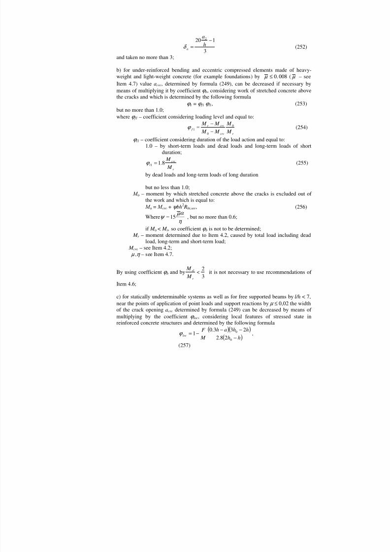
Example 56. Given: free supported bam of the floor with the spanl = 5.5 m, loaded by thedistributed loads: temporary long-duration equivalent loadv = 30 kN/m and dead loadg = 12.5 kN/m; dimensions of the cross sectionb = 200 mm,h = 400 mm,hо = 370 mm;heavy-weight concreteВ 15 (Rbt,ser = 1.15 MPa; E b = 2,05104 MPa); two-legs stirrupsmade of reinforcementА-I ( Е s = 2.1105 MPa) with the spacings = 150 mm, diameter 8mm (Аsw = =101 mm2).
It is required to make the calculation of inclined cracks.C a l c u l a t i o n . Let’s check if the calculation of cracks is necessary according to condition(248).Maximum shear force in the cross section is:
( ) ( ) 1172
5.55.123022max =
+=
+==
lgvqlQ kN
Due to Table 21, b3 = 0.6. b3 Rbt,ser bho = 0.61.15200370 = 51060 N <Qmax = 117 kN,that means inclined cracks are formed and the calculation is required.
The calculation is made due to Item 4.11. Let’s determine valuesQ andQb1.q1 = g + v /2 = 12.5 + 30/2 = 27.5 kN/n; b4 = 1.5 (see Table 21).As 0.2 b4 Rbt,ser b = 0.21.51.15200 = 56.9 N/mm> q1 = 27.5 N/mm, during determinationof Qb1 andQ valueс is taken equal toс = 2hо = 2370 = 740 mm.So
51060740
37020015.15.15.08.0 220,4
1 ==c
bh RbQ ser bt
b
N;
Q = Qmax – q1 с = 117 – 27.5 · 0.740 = 96.65 kN.
Let’s determine the stress in the stirrups by formula (267):235183150
3701015106096650
,0
1 =<=−
=−
= ser ssw
bsw R MPas
h A
QQσ MPa
Due to Items 4.7 and 4.11, l = 1.5;η = 1.3;d w = 8 mm.
00337.0150200
101===
s
sww b
A µ ;
24.101005.2101.2
4
5
===b
s
E E
α
Let’s determine the width of inclined cracks opening by formula (266):
( ) ( )219.0
00337.024.10211005.215.03708101.2
3.181836.05.12115.0
6.045
0
=++
=++
=vb
ws
wswlcrc
E hd
E d a
αµ η σ
mmwhich is less than maximum allowable valueа сrc = 0.3 mm (see Table 1).
CALCULATION OF ELEMENTS OF REINFORCED CONCRETE STRUCTURES ASREGARDS THE DEFORMATIONS
4.12(4.22) Deformations (deflections, angle of rotation) of elements of reinforced concretestructures must be calculated due to formulas of structural theory by means of

8/10/2019 Guidelines for Design of Concrete and r.c.structures_part2.ENG
http://slidepdf.com/reader/full/guidelines-for-design-of-concrete-and-rcstructurespart2eng 32/111
determination of curvature values in compliance with instructions of Items 4.13 –4.21.
4.13(4.23) . Curvature is determined:a) For parts of the element where there are no cracks normal to the longitudinal axisof the element (see Item 4.1) – as for the solid body;b) For the parts of the element where there are cracks normal to the longitudinal axisof the element – as the ratio of the difference of average deformations of the end fibreof the compressed concrete zone and longitudinal stretched reinforcement to theworking height of the element section.
During calculation of deformations the force from the concrete settlement N shr is takenequal to zero.
Determination of reinforced concrete elements curvature on the parts without cracksin the stretched zone
4.14(4.24) . On the parts where there are no normal to the longitudinal axis of the elementcracks total value of the curvature must be determined by the following formula
21
111
+
=r r r
(269)
where1
1
r 2
1
r
– the curvature caused by short-term loads (determined due to
Item1.12) and by dead loads and long-duration temporary loads determined bythe following formulas:
red bb
sh
I E
M
r 11
1
=
;
(270)
red bb
bl
I E
M
r 1
2
1
1
=
;
b1 – coefficient considering the influence of short-duration creep of concrete and taken equalto:for heavy-weight, light-weight and fine concrete with dense fineaggregate................................................... 0,85for light-weight and porous concrete with fineaggregate..........................................................0,70 b2 – coefficient considering influence of long-duration creep of concrete onthe deformations of the element without cracks taken due to Table 31.

8/10/2019 Guidelines for Design of Concrete and r.c.structures_part2.ENG
http://slidepdf.com/reader/full/guidelines-for-design-of-concrete-and-rcstructurespart2eng 33/111

8/10/2019 Guidelines for Design of Concrete and r.c.structures_part2.ENG
http://slidepdf.com/reader/full/guidelines-for-design-of-concrete-and-rcstructurespart2eng 34/111
For light-weight and porous concrete of classВ7.5 and less... 0.7 f – coefficient determined by formula (277);
ξ = x/h o – is determined due to instructions of Item 4.16;v – coefficient which characterizes the elastic-plastic state of concrete of the
compressed zone and taken equal to:
by short-duration action of the load – to coefficientvsh = 0.45;by long-duration action of the load – to the coefficientvl, determined by Table 31.
For bending and eccentric compressed elements made of heavy-weight concrete M r < M o curvature can be determined considering the work of stretched concreteabove the crack using the following formula
tot crc
crcr
crccrc M M
M M
M M
r r r r −−
−
+
=00
1111 (272)
where
21
1 bred bb
crc
crc I E Nr M
r
+=
; (273)
0
1
r
– curvature determined by formula (271) by the moment М s , which is equal:
for bending moments М s = М o;for eccentric compressed moments M s = М o + N уsr;
уsr = yo – а + r – distance from the center of gravity of stretched reinforcement to the axisgoing through the most distant heart point (see Item 4.2);
М r – moment determined due to Item 4.2 caused by total load including dead load,long-term and short-term load;
М o – moment by which stretched concrete above the cracks is excluded out of thework and which is determined by formula (256), whereψ is halved byconsideration of long duration of dead loads and long-term loads;
M crc ,r – see Item 4.2; M, M tot – moment of external forces relating to the axis going through the center of gravity
of the section caused by the load under review and by total load; b1 , b2 – see Item 4.14; by short duration action of the load b2 = 1.0.
4.16.(4.28). Valueξ is determined by formula
( ) 55.11
5.1
1051
1
0
mhe s
f
µα λ δ β
ξ +
±+++
= (274)
but taken no more than 1.0, at the same timees /ho is taken no less than 0.5.
For bending elements the last summand of the right part of formula (274) is takenequal to zero.
In formula (274) top signs are taken by compression force and lower signs – bycompression force N .
In formula (274): β – coefficient taken equal to:

8/10/2019 Guidelines for Design of Concrete and r.c.structures_part2.ENG
http://slidepdf.com/reader/full/guidelines-for-design-of-concrete-and-rcstructurespart2eng 35/111

8/10/2019 Guidelines for Design of Concrete and r.c.structures_part2.ENG
http://slidepdf.com/reader/full/guidelines-for-design-of-concrete-and-rcstructurespart2eng 36/111
( )0
2
8.15.3
125.1
he s
m
mmlss
ψ
−
−−−=
(280)
but no more than 1.0, at the same time it is necessary to takees /h o ≥ 1,2/ ls.For bending elements the last part of the right part of formula (280) is taken equal tozero.In formula (280): ls – coefficient considering influence of duration of the load action and taken incompliance with Table 32;
r
plser bt m M
W R ,= (281)
T a b l e 32(36)
Duration of the load action Coefficient ls by concrete classВ10 and more В7.5 and less1. Short duration byreinforcement classes:А-II,А-III 1,1 0,8А-I, Вр-I 1,0 0,72. Long duration 0,8 0,6
But no more than 1.0;HereW pl – see Item 4.3;
M r – see Item 4.2.
4.18. Curvature of eccentric stretched elements with longitudinal force N, applied betweencenters of gravity of areas of reinforcementS andS ′ , on the parts with normal cracksin the stretched zone is determined by the following formula:
+−=
ss
s
ss
s
s
s
sss
s
A E A E z
Ne
A E z
N
r
'
21 ψ ψ ψ (282)
where zs = ho – a ′ – distance between centers of gravity of reinforcement areasS andS ′ ;
ψ s, ψ′ s – coefficients which consider the work of stretched concrete forreinforcementS andS ′ and determined by formulas:
N N crc
lss ψ −= 1 (283)
N N crc
lss
'' 1 ψ −= (284)
here ls – coefficient taken equal to:
by short duration of the load action........................................... 0,70by long duration of the load action............................................ 0,35
N crc , N ′ crc – forces applied in the same point that force N and corresponding to crackformation in the most and the least stretched zone of concrete values N crc and N ′ crc aredetermined by the following formulas:

8/10/2019 Guidelines for Design of Concrete and r.c.structures_part2.ENG
http://slidepdf.com/reader/full/guidelines-for-design-of-concrete-and-rcstructurespart2eng 37/111
r e
W R N plser bt
crc +=
0
, .
(285)
0
,'
'
'
er
W R N plser bt
crc
−=
and taken no more than N ; besides byr' < ео value N ′ crc is taken equal to N.
In formulas (285):W pl, W ′ pl – valuesW pl, determined due to Item 4.3 correspondingly for the most and
the least stretched side of the section;r , r ′ – distances from the center of gravity of the section to the heart points which
are most distant from the most and the least stretched side of the section;valuesr andr ′ are determined by formula (242).
4.19. Curvature of eccentric stretched elements with longitudinal force N, applied beyondthe centers of gravity of reinforcement areasS andS ′ , and byeо < 0,8hо is determined
by means of linear interpolation between curvature I r
1 determined by formula (282)
by еs = 0 (that means byeо = yso, where yso – is the distance from the center of gravity
of reinforcement areaS to the center of gravity of the section), and curvature II r
1
determined by formula (271)еs =0,8ho - yso (that means byео = 0,8hо). Thancurvature value is:
008.01111
s
s
I II I yh
e
r r r r −
−
+
= (286)
4.20. For elements of rectangular section with symmetric reinforcement under skeweccentric pressure curvatures are determined by the following formula
β / 110
=r r
(287)
where0
1
r
– curvature calculated as for the flat eccentric compression due to Item
4.15 – 4.17 on the assumption of the force action N with theeccentricityеo in he plane of he symmetry axis х , at the same time it’saccepted that force plane is located between axis х and the sectiondiagonal;
β – coefficient considering the influence of the angle of slope of the forceplane on the deformation value of skew compressed elements anddetermined by the following formula
( )
−−−
+
+−−= β
π β β
αµ αµ
π β 2
cos12.412.41
1213
x
y
x
y
h
h; (288)
A
Asx x = µ ;
A
Asy y = µ
8/10/2019 Guidelines for Design of Concrete and r.c.structures_part2.ENG
http://slidepdf.com/reader/full/guidelines-for-design-of-concrete-and-rcstructurespart2eng 38/111

8/10/2019 Guidelines for Design of Concrete and r.c.structures_part2.ENG
http://slidepdf.com/reader/full/guidelines-for-design-of-concrete-and-rcstructurespart2eng 39/111
Determination of deflections
4.22 (4.31). Deflection f m caused by the deflection deformation is determined by thefollowing formula
dxr
M f x
l
xm
= ∫ 1
0
(293)
where x M bending moment in the section х caused by the unit-force applied in thedirection of required displacement of the element in the section along thespan length for which the deflection is determined;
xr
1 total value of he element curvature in the section х caused by the load by
which the deflection is calculated.
By determination of the deflection in the middle of the span formula (293) can get thefollowing view:
( ) ( ) ( ) ( )( )
−+
+
+
+
= ∑−
= mir il
n
ir lm r
nr r
ir r n
l f
1231161112
12 /
1002
2
(294)
where( )0
1lr
,
( )0
1r r
curvatures of the element in the left and the right support;
( )ilr
1 ,
( )ir r
1 ,
mr
1 curvatures of the element in the sectioni, in the
symmetrical sectioni' (draft 87) and in the middle of thespan;
п – even number of equal parts on which the span of the element is divided;numberп is to be taken no less than 6.
Draft 87. Diagram of the curvature in the reinforced concrete element with variable section along theperimeter
In formulas (293) and (294) curvaturesr 1 are determined by formulas (269) and
(292) correspondingly for the parts without cracks and with cracks; signr
1 is taken in
compliance with the curvatures diagram.
By determination of deflections of statically undeterminable structures it isrecommended to consider redistribution of moments caused by cracks formation andnon-elastic deformations of concrete.
For bending elements of constant section which have cracks on each part withinwhich bending moment has no any sign the curvature can be calculated for the moststressed section taking it for other sections of the same part variable proportionallywith the values of bending moment (Draft 88).

8/10/2019 Guidelines for Design of Concrete and r.c.structures_part2.ENG
http://slidepdf.com/reader/full/guidelines-for-design-of-concrete-and-rcstructurespart2eng 40/111
Draft 88. Diagrams of bending moments and curvature in the reinforced concrete element of constantsectionа — load distribution scheme;б — bending moments diagram;в curvature diagram
4.23 (4.32, 4.33). For bending elements by 10<h
l it is necessary to consider the influence
of shear forces on their deflection. In that case total deflection f tot is equal to the sumof deflections caused by deformations of deflection f m and deformation ofdisplacement f q.
Deflection f q, caused by deformation of displacement is determined by the followingformula
∫=l
x xq dxQ f 0
γ (295)
where xQ – shear force in the section х caused by the directed to the required
displacement unit force applied in the section where deflection isdetermined;γ x – shear deformation determined by the following formula
crcb x
x GbhQ
γ 25.1= (296)
here Q x – shear force in the section х caused by external load; b2 – coefficient considering influence of long-duration creep of concrete
and taken according to Table 31; by short-duration action of the load b2 = 1.0;
G – concrete displacement module (see Item 2.12); crc – coefficient considering influence of cracks on displacementdeformations taken equal to:
- On the parts along the length of the element where there are nonormal and inclined to the longitudinal axis of the elementcracks.................... 1,0;
- On the parts where there are only inclined to the longitudinal axisof the element cracks....................... 4,8;
- On the parts where there are only normal or normal and inclined tothe longitudinal axis of the element cracks – due to formula
x x
red bcrc r M
I E
=13
(297)
here M x xr
1 – correspondingly moment and curvature in the section caused by the
load by which deflection is determined by its short duration.
4.24.(4.34). For solid slabs no less than 250 mm thick reinforced by flat meshes with cracksin the stretched zone values of deflections calculated by formula (293), are multiplied
by the coefficient3
0
0
7
−h
h taken no more than 1.5 whereh – in mm.

8/10/2019 Guidelines for Design of Concrete and r.c.structures_part2.ENG
http://slidepdf.com/reader/full/guidelines-for-design-of-concrete-and-rcstructurespart2eng 41/111
Determination of longitudinal deformations
4.25. Relative deformationsε o (elongation or shortening) in the direction of thelongitudinal axis of elements are determined in the following manner.
1. Relative deformations of eccentric compressed and eccentric stretched elementswith one-valued diagram of stresses:
а) for eccentric compressed elements or their single parts – by formula
00 22 y
I vE Ne
AvE N
red bred b
±=ε (298)
b) for eccentric stretched elements or its parts if there are no cracks – by formula
01
20
1
20 y
I E
Ne
A E
N
red bb
b
red bb
b
ε ±−= (299)
In formulas (298) and (299) sign «plus» corresponds to deformations of shortening,sign «minus» – to deformations of elongation;
c) for eccentric stretched elements or their parts if there are cracks (that means forelements mentioned in Item 4.18) – by formula
( )s
sssmssm
z y z y −+
−= ε ε
ε '
0 (300)
whereε sm, ε′ sm – average values of elongation of reinforcementS andS', determinedby formulas:
( )s
sss
sssm z A E
e z N ψ ε
−=
(301)'
''
ssss
ssm z A E
Neψ ε =
here zs, ψ s, ψ′ s – see Item 4.18.
2. Relative deformations of bending, eccentric compressed and eccentric stretchedelements with double-valued diagram of stresses in the section:
а) for elements or their parts without cracks in the stretched zone – by formula
01
20 2 y I E
M AvE
N red bb
b
red b ε ±±= . (302)
Rule of signs is the same like for formulas (298) and (299);
b) for parts of elements mentioned in Item 4.15 which have cracks in the stretchedzone – by formula
( )0
00 h
yh y ssmsbm −−=
ε ε ε (303)
whereε sm, ε bm – average values of relative elongation of reinforcement and relative
shortening of end compressed fibre of concrete on the part between cracks determinedby the following formulas:
8/10/2019 Guidelines for Design of Concrete and r.c.structures_part2.ENG
http://slidepdf.com/reader/full/guidelines-for-design-of-concrete-and-rcstructurespart2eng 42/111
= N z
M A E
s
ss
ssm
mψ
ε (304)
( ) v E bh z
M
b f
sbsm
0ξ ψ
ε +
= (305)
where M s, ψ s, z, f , ξ – see Items 4.15 – 4.17; rules of signed see in Item 4.15;
c) for the parts of eccentric stretched elements mentioned in Item 4.19 – by means oflinear interpolation between valueε о determine by formula (300) byеs = 0 (thatmeans byеo = yso) and valueеo determined by formula (303) byеs = 0,8ho (that meansby еo = 0,8 ho + yso) where yso – see Item 4.19.
In formulas (298) – (305): ys – distance from the fibre under review to the center of gravity of reinforcementS ; у
о – the same to the center of gravity of the section; b1, b2 – see Item 4.14; by short-duration action of the load b2 = 1.0;v – see Item 4.15.
Deformationsε о, determined by formulas (298) – (303) with sign «plus» correspondto shortening, with sign «minus» – to elongation.By dead loads, long-term and short-term loads acting at the same time valueε о is tobe determined similar to determination of total curvature due to Item 4.21.
4.26 . Shortening (elongation) of elements at the level of considered fibre is determined bythe following formula
∑=
=∆n
iioi ll
1ε (306)
whereε оi – relative longitudinal deformations in the section, located in the middle ofthe part with the lengthli;
п – quantity of parts on which the length of the elements is divided.
Approximate methods of deformations calculation
4.27 . Deflections of reinforced concrete bending elements made of heavy-weight concreteof constant section, used by normal and high humidity (air humidity more than 40
percent) are obvious less than maximum allowable deflections if the followingcondition is met
lim0
λ ≤hl (307)
whereλ lim – limit ratio of the span to the working height of the section less thanwhich examination of deflections is not required (Table 33).
By 10<hl deflections are les than maximum allowable ones if condition (308) which
considers influence of shear deformations on the element deflection is met:
lim00
:18 λ ≤+hl
hl (308)

8/10/2019 Guidelines for Design of Concrete and r.c.structures_part2.ENG
http://slidepdf.com/reader/full/guidelines-for-design-of-concrete-and-rcstructurespart2eng 43/111

8/10/2019 Guidelines for Design of Concrete and r.c.structures_part2.ENG
http://slidepdf.com/reader/full/guidelines-for-design-of-concrete-and-rcstructurespart2eng 44/111
f = f t = 0,2 3423
2517
1914
1611
129
108
1010
1111
1111
f = f t = 0,6 4833
3425
2618
2114
1612
159
118
1010
1111
f = f t = 1,0 5542
4436
3621
2617
2014
1712
149
119
109
As = A ′ s
N o t e . Valuesλ lim, given above the line are used by the calculation of the elements reinforced by steel ofА-II,under the line – of class A-III.
If maximum allowable deflections f (see Item 1.17) are less than200
l , so valuesλ lim
of Table 33 must be decreased by
l f :
2001 times (for example if
3001
=l
f – by 1,5
times, if4001
=l
f – by 2 times).
For solid slabs less than 250 mm thick reinforced by flat meshes valuesλ lim aredecreased by means of dividing into the coefficient mentioned in Item 4.24.
N o t e . Valuesλ lim can be decreased in the following cases:а) if deflection is determined by action of moment M l which is the part of the total moment М tot (positions 2 – 4 of Table 2) – by means of multiplying ofλ lim Table 33 by the ratio М tot / M l;
b) if load is different from the distributed load – by means of multiplying λ lim Table 33 by the
ratio m p:485
where рm is coefficient taken due to table 35 according to the loading scheme;
в) if deflection is determined according to the combined work of short-term loads, long-term loads anddead loads – by means of multiplyingλ lim of Table 33 by coefficient θ , determined by the following
formula
( )11 −+=
θ
θ θ
tot
l
M M
whereθ – ration between the deformation caused by long action of the load and deformation caused byshort duration of the same load taken equal to: θ = 1,8 – for elements of rectangular section;θ = 1,5 for elements of T-section with a flange in the compressed zone;θ = 2,2 – for elements of T-section with a flange in the stretched zone.

8/10/2019 Guidelines for Design of Concrete and r.c.structures_part2.ENG
http://slidepdf.com/reader/full/guidelines-for-design-of-concrete-and-rcstructurespart2eng 45/111
DETERMINATION OF CURVATURE
4.28. For bending elements made of heavy-weight concrete of constant section mentionedin Item 4.15 and used by environment air humidity higher than 40 percent
curvaturer 1
on the parts with cracks is determined by the following formula
201
,2
21h A E
Rbh M
r ss
ser bt
−
= (309)
where 1, 2 – see Table 34.
By dead loads, long-term loads and short-term loads acting at the same time curvature
r 1 is determined by the following formula
−+=
l
ser bt ll
sh
sh
ss
Rbh M M
h A E r 1
,2
2
120
11
(310)
где 1sh — coefficient 1 by short duration of the load; 1l, 2l — coefficients 1 and 2 by long duration of the load.
DETERMINATION OF DEFLECTIONS
4.29. For bending elements by 10≥hl deflection f is determined by the following manner:
а) for elements of constant section which work as free supported or console beams –by formula
21 lr
f mm
ρ
= (311)
wheremr
1 – curvature in the section with maximum bending moment caused by the
load by which the deflection is determined; рm – coefficient taken due to Table 35;
by the loading scheme of a free supported or a console beam not given in Table 35,the deflection is determined by formulas of materials resistance by rigidity equal tothe ratio between maximum moment and maximum curvature;
b) if deflection determined due to sub-item «а» is more than maximum allowablevalue for under-reinforced elements ( µ ≤ 0.5 percent) this value is to be determinedmore exact due to considering of increased rigidity on the parts without cracks byvariable rigidity on the parts with cracks; for free supported beams loaded bydistributed load it corresponds to the following formula
2
,
111l
r r r f crc
elmmm
m
−
−
= ρ ρ (312)

8/10/2019 Guidelines for Design of Concrete and r.c.structures_part2.ENG
http://slidepdf.com/reader/full/guidelines-for-design-of-concrete-and-rcstructurespart2eng 46/111

8/10/2019 Guidelines for Design of Concrete and r.c.structures_part2.ENG
http://slidepdf.com/reader/full/guidelines-for-design-of-concrete-and-rcstructurespart2eng 47/111
where рcrc – coefficient taken due to Table 36 according to the ratio M crc / M tot ( M crc –see Items 4.2 and 4.3) ;
elmr ,
1
– curvature in the section with maximum moment determined as for a
solid body by formula (270) caused by the load by which the deflectionis determined; it is possible to determine value I red in formula (270) asfor a concrete element.
For other loading schemes value f can be determined by formula (314);
For bending elements with built-in supports deflection in the middle of the span isdetermined by the following formula
( ) ( )
2
00 81115.01
lr r r
f mr l
mm
−
+
−
= ρ ρ (313)
wheremr
1
( )01
lr
( )01
r r
– curvature of the element in the middle of the span, on the
right and on the left support; рm – coefficient determined due to Table 35 as for a free supported beam;
d) for elements of variable section, as well as in cases when more exact determinationof deflections is required than by formulas (311) and (313), and the elements and theloads are symmetric relating to the middle of the span deflection is determined by thefollowing formula
+
+
+
=
mr r r r
l f
18112161216 210
2
(314)
where0
1
r 1
1
r 2
1
r mr
1 – curvatures on the support, at the distancel
61 from the
support, at the distancel31 from the support and in the middle of the
span; values of curvatures are calculated with their signs due to thecurvatures diagram.
In other cases curvature in the middle of the span is to be determined by formula(294).
Curvature values included into formulas (311) – (314) are determined by formulas(271), (272), (282), (286), (309) and (310) if there are cracks in the stretched zone andby formulas (269) and (270) – if there are no cracks.
For solid slabs less than 250 mm thick it is necessary to take into accountrecommendations of Item 4.24.
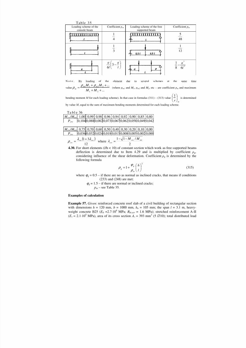
8/10/2019 Guidelines for Design of Concrete and r.c.structures_part2.ENG
http://slidepdf.com/reader/full/guidelines-for-design-of-concrete-and-rcstructurespart2eng 48/111

8/10/2019 Guidelines for Design of Concrete and r.c.structures_part2.ENG
http://slidepdf.com/reader/full/guidelines-for-design-of-concrete-and-rcstructurespart2eng 49/111

8/10/2019 Guidelines for Design of Concrete and r.c.structures_part2.ENG
http://slidepdf.com/reader/full/guidelines-for-design-of-concrete-and-rcstructurespart2eng 50/111

8/10/2019 Guidelines for Design of Concrete and r.c.structures_part2.ENG
http://slidepdf.com/reader/full/guidelines-for-design-of-concrete-and-rcstructurespart2eng 51/111
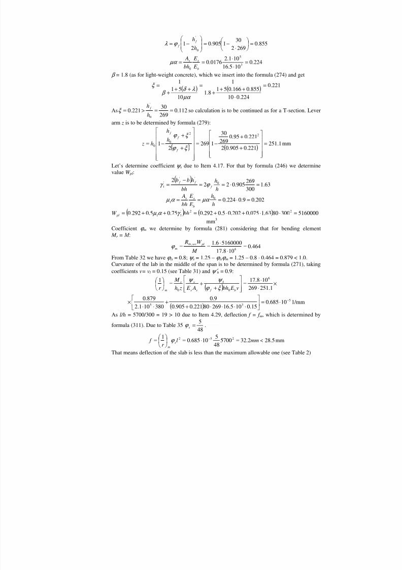
8/10/2019 Guidelines for Design of Concrete and r.c.structures_part2.ENG
http://slidepdf.com/reader/full/guidelines-for-design-of-concrete-and-rcstructurespart2eng 52/111
855.02692301905.0
21
0
'
=
−=
−=
h
h f f λ
224.0105.16101.20176.0 3
5
0
===b
ss
E E
bh A
µα
β = 1.8 (as for light-weight concrete), which we insert into the formula (274) and get
( ) ( ) 221.0
224.010855.0166.0518.1
1
10511
=++
+=
+++
=
µα λ δ
β ξ
As 112.026930221.0
0
'
==>=h
h f ξ so calculation is to be continued as for a T-section. Lever
arm z is to be determined by formula (279):
( ) ( ) 1.251221.0905.02
221.095.0269
30
12692122
0
'
0 =+
+−=
+
+−=
ξ
ξ
f
f f
h
h
h z mm
Let’s determine coefficientψ s due to Item 4.17. For that by formula (246) we determinevalueW pl:
( )63.1
300269905.022
2 0''
'1 ===
−=
h
h
bh
hbb f
f f γ
202.09.0224.001 ====
h
h
E
E
bh
A
b
ss µα α µ
( ) ( ) 51600003008063.1075.0202.05.0292.075.05.0292.0 22'11 =++=++= bhW pl γ α µ mm3
Coefficient m we determine by formula (281) considering that for bending element M r = М :
464.0108.17
51600006.16
, === M
W R plser bt m
From Table 32 we have ls = 0.8;ψ s = 1.25 – ls m = 1.25 – 0.8 0.464 = 0.879 < 1.0.Curvature of the lab in the middle of the span is to be determined by formula (271), takingcoefficientsv= v l = 0.15 (see Table 31) andψ′ b = 0.9:
( ) ×=+
+= 1.251269 108.1716
00 v E bh A E zh M
r b f
b
ss
ss
m ξ ψ ψ
( )5
35 10685.015.0105.1626980221.0905.0
9.0380101.2
879.0 −=+
+× 1/mm
As l/h = 5700/300 = 19 > 10 due to Item 4.29, deflection f = f m, which is determined by
formula (311). Due to Table 35485
=s .
5.282.32570048510685.01 252 <==
= − mmlr
f sm
mm
That means deflection of the slab is less than the maximum allowable one (see Table 2)
8/10/2019 Guidelines for Design of Concrete and r.c.structures_part2.ENG
http://slidepdf.com/reader/full/guidelines-for-design-of-concrete-and-rcstructurespart2eng 53/111
5. CONSTRUCTIVE REQUIREMENTS
GENERAL POSITIONS
5.1.(5.1). During design of concrete and reinforced concrete structures and details toprovide their economic and quality manufacturing, required durability and cooperationwork of concrete and reinforcement it is necessary to follow constructive requirementof the present section.
5.2. Structures must be of simple shape. It is recommended to use reinforcement, embeddedelements and lifting loops which are manufactured in form of finished productsaccording to norms and state standards. Reinforcement must be designed in form ofenlarged blocks and spatial frameworks to spend less time to put them into theframework.
It is necessary to take minimum possible stripping strength and transporting strength oconcrete for effective use of industrial areas.
It is necessary to aim at unification of reinforcement and embedded elements in somestructures and their series, at little number of different marks and diameters of steel,types of reinforcement elements – mashes and frameworks, spacing of longitudinal andcross rods.
MINIMUM DIMENSIONS OF ELEMENTS SECTIONS
5.3.(5.2). Minimum dimensions of the section of concrete and reinforced concrete elementsdetermined due to the calculation as regards corresponding forces and correspondinggroups of limit states must be specified considering economical requirements, necessityto unify framework forms and reinforcement as well as conditions of acceptedtechnology of structures manufacturing.
Besides dimensions of elements sections must be taken so that to follow therequirements of reinforcement location in the section (thickness of concrete protectionlayers, distance between rods, etc) and anchorage of reinforcement.
5.4.(5.3). Thickness (Note: Hereinafter values of sections dimensions, thickness of
protection layer of concrete and other terms mentioned in the present Guidelines belonto nominal values specified during design and shown on projects. These NominalValues can vary in the reality but variations must not exceed values given in thecorresponding state standards technical specifications and other documents) of solidslabs must be taken in millimeters no less than:
for roofs........................................................................................ 40for floors of civil and public buildings......................................... 50for floors of industrial buildings……………………................... 60for slabs of light-weight concreteВ7,and less in all cases ......... 70
Minimum thickness of prefabricated slabs must be determined due to condition ofproviding of required thickness of concrete protection and conditions of reinforcemenlocation in the slab (see Items 5.32 – 5.41).

8/10/2019 Guidelines for Design of Concrete and r.c.structures_part2.ENG
http://slidepdf.com/reader/full/guidelines-for-design-of-concrete-and-rcstructurespart2eng 54/111
Dimensions of sections of eccentric compressed elements must be taken so that theirelasticity lo /i in any direction as a rule was not more than:
For concrete elements............................................... 200 (for rectangular sections bylo /h ≤ 60)For columns which are elements of buildings…...... 120 (bylo /h ≤ 35)
For concrete elements............................................... 90 (for rectangular sections by lo /h ≤ 26)
DIMENSIONS AND SHAPES OF ELMENTS OF STRUCTURES
5.5. Dimensions of prefabricated concrete and reinforced concrete elements must bespecified considering carrying capacity and dimensioning restrictions of technologicaltransport and installation equipment in the factories and on the building sites. In case oneed it is necessary to consider the possibility to lift a reinforced concrete element withthe form.
5.6. To avoid damages caused by local concentrations of stresses by abrupt changing ofdirection of the element surfaces (for example in internal angles) it is necessary toprovide flattening of contours in form of slopes, sloped edges or curving of littledimensions (up to 50 mm) in order not to make local reinforcement (Draft 90,а, б, в).In external sharp corners it is necessary to make sloped edges or curving to avoidchipping of concrete (Draft 90,г).
Draft 90. Sloped edges and curvingа – curving in the ribbed slab;б – sloped edge between a flange and a wall in a T-beam;в – combination ofthe sloped edge and a curving in the joint of the truss;г – flattening of the sharp corner in the collar-beam;д –curving in the hole for communications, strapping, etc.
5.7. Holes in reinforced concrete elements for communications, stripping, etc must be nobig and located within the cells of reinforcing meshes and frameworks so not to cut thereinforcement and not to make local reinforcement. Corners of the hole must be smooth(Draft 90,д).
5.8. During design of concrete and reinforced concrete structures their shapes must bespecified considering the form and conditions of use of the formwork.
By using of forms with a drop side the shape of a detail must not prevent the turning ofthe side (Draft 91,а) when removing the formwork.
By using solid molds to remove the detail out of the formwork it is necessary to designtechnological slopes no less than 1:10 (Draft 91,б, в). In case of use of solid forms withpressing out the slope must be no less than 1:15 (Draft 91,г).
By immediate removal of formworks with fixed vertical moving of the forming elemen(to avoid crashing of concrete) (Draft 91,д, е) the slope must be no less than 1:50.
By using of forms with one fixed and one drop side to provide vertical lifting of thestructure by removing of the framework it is used changing from the larger to the less
width of the detail [for example from the lower flange to the wall (Draft 91,ж)]; it must

8/10/2019 Guidelines for Design of Concrete and r.c.structures_part2.ENG
http://slidepdf.com/reader/full/guidelines-for-design-of-concrete-and-rcstructurespart2eng 55/111
be smooth at the angle no less than 45 degrees. This requirement can be not consideredif the framework has a pressing-out system (Draft 91,з).
Using of pressing out and immediate remain of the form work must be approved by themanufacturer.
Draft 91. Technological slopesа – in a form with drop sides;б, в – in the solid form;г – the same by using pressing out;д, е – byimmediate removal of the formwork;ж – in a form with a solid side;з – the same by using pressing out;1 – detail; 2 – form; 3 – drop side; 4 – pressing out; 5 – bearing brass; 6 – forming frame
REINFORCEMENT, MESHES AND FRAMEWORKS
Separate reinforcing rods
5.9. Assortment of reinforcing rods for reinforced concrete structures is given in Annex 4.
5.10. During design of reinforced concrete structures especially with great volume ofreinforcement it is necessary to consider the following characteristics of reinforcingrods:
- Dimensions of cross sections of profiled section rods considering allowabledeviations;
- Bending radius of rods and dimensions of bent elements;- Allowable deviations from the project dimensions by arrangement of rods
welding meshes and frameworks, embedded elements etc.
5.11. during design of bent rods diameters and angles of bending must meet the
requirements of Table 37. Length of bent rods is determined due to the axis of the rod.Table 37
Reinforcement classMinimum clear diameter of by the rod
diameterd , mmMaximum angle of
bending,18 and less 20 and more grad
А-I, Ас -II, mark 10ГТ 2.5d 2.5d Not limitedА-II 4d 6d 180A-III 6d 8d 90*Вр-I 4d Not limited
* It is possible to bend the rods at 180 degrees if design resistance against tension is decreased by 10 percent.
Dimensions of hooks for anchorage of plain rods of reinforcement must be takenaccording to Draft 92.
Draft 92. Dimensions of hooks at the ends of rods of plain main reinforcement
Welded connections of reinforcement
5.12.(5.32). reinforcement of hot-rolled steel of plain and profiled sections, heat-treatedsteel-classАт -IIIС and simple reinforcing wire, are made as a rule by means of

8/10/2019 Guidelines for Design of Concrete and r.c.structures_part2.ENG
http://slidepdf.com/reader/full/guidelines-for-design-of-concrete-and-rcstructurespart2eng 56/111
contact welding – point welding and butt-seam welding. It is possible to use semi-automatic arch welding, as well as manual welding due to Item 5.18.
5.13 (5.33). Types of welding connections and welding methods must be chosenconsidering use conditions and welding capacity of steel, technical-economicalindexes and technological capabilities of the manufacturing factory in compliancewith the instructions of state standards and technical specifications for weldedreinforcement (Table 38).
Connections not mentioned in the current standard documents can be produced inaccordance with the projects approved in compliance wit the established procedure.
End joints can be made without using welding by means of swedge casings incompliance with the approval of the manufacturing factory.
5.14.(5.34). In the plant conditions during producing of welded reinforcing meshes,frameworks and connections it is necessary to use contact welding along the length osome rods – point welding and butt-seam welding (see positions 1, 2 and 5 of Table38).
5.15.(5.35). During installation of reinforcement details and prefabricated reinforcedconcrete structures for connection for butt jointing of rods with diameter 20 mm andmore it is necessary to use “tub” welding in special copper or graphite removableforms (see positions 7-9 Table 38), as well as “tub” welding, bath-seam welding andmulti-layer welding on steel cover-brackets1 [a cover-bracket – additionalconstructive detail, taking a part of the axis load, whose section area is no more than50 percent of the connected rod section area] (see positions 10-13 of Table 38). At thesame time first of all it is necessary to use power-activated methods of welding (seepositions 7, 8, 10, 12 of Table 38), providing quality control of connections. In specialcases it is possible to use welding of vertical rods by means of multi-layer weldingwithout additional elements (see position 14 of Table 38).
5.16. Design of butt welding joints using prefabricated forms and other forming elements ismade considering the following requirements:
а) distance between connected rods, as well as distance from the connected rods to the
nearest surface of the reinforced concrete element must be taken considering thepossibility of installation of forming elements and removal of prefabricated forms.Dimensions and methods of installation of prefabricated forms of steel cover-bracketsmust be taken due to standard documents for welding. Total free length ofreinforcement rods must conform to the distance between surfaces of connectedreinforced concrete elements and must be no less than 350 mm. Distance from thebutt-ends of free length of reinforcement rods to the surfaces of elements (consideringprotection of concrete against overheating) is taken no less than 100 mm (Draft 93,а);
б) location of connected rods must provide the possibility to insert an electrode atangle no more than 30 degrees to the vertical line (Draft 93,б, в);

8/10/2019 Guidelines for Design of Concrete and r.c.structures_part2.ENG
http://slidepdf.com/reader/full/guidelines-for-design-of-concrete-and-rcstructurespart2eng 57/111

8/10/2019 Guidelines for Design of Concrete and r.c.structures_part2.ENG
http://slidepdf.com/reader/full/guidelines-for-design-of-concrete-and-rcstructurespart2eng 58/111
Ta b l e 38
Symbol of the weldingdue to GOST 14098-85
Method of welding
Number of the positionof Table 1 of СН 393-78
Position of therod by the
welding
Class (mark) ofreinforcement
steel
Diameter of rods,mm
Scheme of theconnection
structure
1. Contact point weldingof two rods
К11А
Horizontal (canbe vertical inconductors)
А-IА-IIА-III
Ат -III С Вр-IВ-I
6 4010 406 40
10 283 53 5
2. the same of three rods К21Б
The same А-IА-IIА-III
Ат -III С Вр-IВ-I
6 4010 406 40
10 283 53 5
3. Manual arch weldingwith point tack weld
К32
Horizontal andvertical
А-IА-II
(Ст5сп2)А-II
(Ст5пс2)Ас -IIА-III
(25 Г2C)Ат -IIIC
10 4010 28
10 1810 3210 28
10 28
InisoaWst
4. the same with forcedforming of the joint
-3
Vertical А-I; А-II; А-IIIАт -IIIC
14 40
14 18
WrocWfo

8/10/2019 Guidelines for Design of Concrete and r.c.structures_part2.ENG
http://slidepdf.com/reader/full/guidelines-for-design-of-concrete-and-rcstructurespart2eng 59/111
Butt joints5. contact butt seam
weldingC1; C2
4AHorizontal А-I
А-П А-III
Ат -IIIC
10 4010 4010 40
10 28 d
d
sppd
6. contact butt seamwelding with thefollowing mechanicaltreatment
С3; С44Б
Horizontal А-IIА-III
Ат -IIIC
10 4010 4010 22
Rw
In prefabricated forms7. bath power-activated
welding flux weldingС5; С8-С11
5А; 6А Fc
in(s
8. arch power-activatedwelding with fluxcored wire
С6; С9; С125Б; 6Б
9. bath mono-electrodewelding
С7; С10; С135В; 6В
Horizontal andvertical
А-I; А-II; А-III 20 40
Wrem
On the steel cover-bracket10. arch power-activated
welding with fluxcored wire
С14; С17-
Horizontal andvertical
А-IА-П А-III
Ат -IIIC
20 4020 4020 4020 28
BА
11. bath seam welding С159Г
horizontal
12. arch power-activatedwelding by open-flame arch with alloywire
С16; С189В; 10 В
Horizontal andvertical
13. manual arch multi-layer welding
С1910Б
Vertical

8/10/2019 Guidelines for Design of Concrete and r.c.structures_part2.ENG
http://slidepdf.com/reader/full/guidelines-for-design-of-concrete-and-rcstructurespart2eng 60/111
14. the same withoutadditionaltechnological
elements
С2011
Vertical А-IА-П А-III
20 40
15. manual arch weldingwith long joints andcovers of rods
-12
Horizontal andvertical
А-IА-П А-III
Ат -IIIC
10 4010 4010 4010 22
Lc–FА
jo16. manual arch welding
with long joints oftwo rods
-13
Horizontal andvertical
А-IА-П А-III
Ат -IIIC
10 4010 2510 2510 18
Lc–Fmsil
N o t e . Instructions for welding of high-strength rod reinforcement of classes A-IV, Ат -IVC, A-V and A-VI are given in SNiP 2.03.01-84 (se85.

8/10/2019 Guidelines for Design of Concrete and r.c.structures_part2.ENG
http://slidepdf.com/reader/full/guidelines-for-design-of-concrete-and-rcstructurespart2eng 61/111
In all other cases including by welding of anchor rods of meshes (see Items 3.44, 5.45and 5.46), welded connections must have standardized strength.
Cross connections with non-standardized strength can be made by means of archwelding with point tack weld (see position 3 of Table 38), as well as by means ofpoint manual welding (see positions 1 and 2 of Table38) by decreased demands to theconnection strength regulated by GOST 10922 – 75, by decreased demands tominimum relative settlementh / d' (see draft of position 1 Table 38) regulated byGOST 14098 – 85, but no less than mentioned in Table 8 ofСН 393-78.
5.20. It is possible to connect the rods by means of welding in any case along the length ofthe detail. Connections (joints) made by arch welding must be located so that theydidn’t prevent concreting, that means it is necessary to make them in points with lessreinforcement, to prevent several joints in one section.
Flat welding meshes 1
[1Hereinafter term «flat welding meshes» includes any flat welded reinforcing details (meshes, frameworks)].
5.21. During design of flat meshes it is necessary to consider the requirements ofunification of dimensions, spacing and diameters of cross and longitudinalreinforcement. Meshes must be transportable, convenient for storage and forinstallation into a form. First of all it is recommended to use ready-mixed meshes ormeshes of centralized manufacturing with dimensions corresponding to statestandards and norms.
Reinforcing meshes which do not meet the mentioned above requirements must bedesigned considering their manufacturing by means of point welding on multi-electrode machines.
5.22. Parameters of wide welded meshes are given in Table 39, of narrow meshes – inTable 40.
In order to reduce the number of realignment of multi-electrode machines it isrecommended to unify the reinforcement spacing during design, basicallylongitudinal reinforcement for reinforced concrete details of the present series orcatalogue.
Ta bl e 39Data for meshesParameters of wide welded
meshes produced on multi-electrode meshes
light heavyAdditional requirements
Diameters of rods, mm:Longitudinal D
Cross rodsd
From 3 to 12
From 3 to 10
From 14 to 32
From 6 to 14
It is recommended one diameter in amesh. Difference no more than twotimes is possible. Each pare of rodscounting from the edge must be ofthe same diameter .
It is necessary to use rods of onediameter

8/10/2019 Guidelines for Design of Concrete and r.c.structures_part2.ENG
http://slidepdf.com/reader/full/guidelines-for-design-of-concrete-and-rcstructurespart2eng 62/111
Spacing of rods, mm:
Longitudinalv
Cross rodss:Constant spacing
Two different spacingfor a strip-mesh:a) bigger
b) smaller
100200300
anyfrom 100 to 300
anyfrom 140 to 300anyfrom 60 to 220
200
100; 200;300; 600
–
–
For light meshes interchange ofspacing is possible. Use of spacingwhich is more than the mentionedones is possible but they must bedivisible by 100 mm. By the mesh
width not divisible by 100 mm therest must be located on one side (seethe draft for the table, type II).Type III can by used in compliancewith the approval of the producingfactory. Strip-mesh1 is produced bydiameters of longitudinal rods D ≤ 8mm.
Minimum difference between thevalue of the bigger and the smallerspacing in one mesh is 80 mm; thesmaller spacing (less than 100 mm) istaken as an additional one as well asin points of cutting of the strip-mesh
Minimum length of the rodsends (distance from the butt-endof the rod to the axis of endcrossed rod), mm:
Cross rodsk
Longitudinalc
20
25
25 but no less than D25
For meshes produced withlongitudinal cutting of the stripk ≥ 50 mmFor a strip-meshc from 30 to 150mm
Maximum mesh length, L, m 12 9 but no more thanthe length of not-connected rods
All cross rods must be taken with thesame length within one mesh
Width of a mesh, mm: A B (on axes of end longitudinal
rods)
From 800 to 3800From 1160 to 3750
From 1050 to 3050From 1000 to 3000
All cross rods must be taken with thesame length within one mesh
Maximum number oflongitudinal rods
36 16 Number of rods must be taken even
1 Is produced in form of continuous part with the following cutting
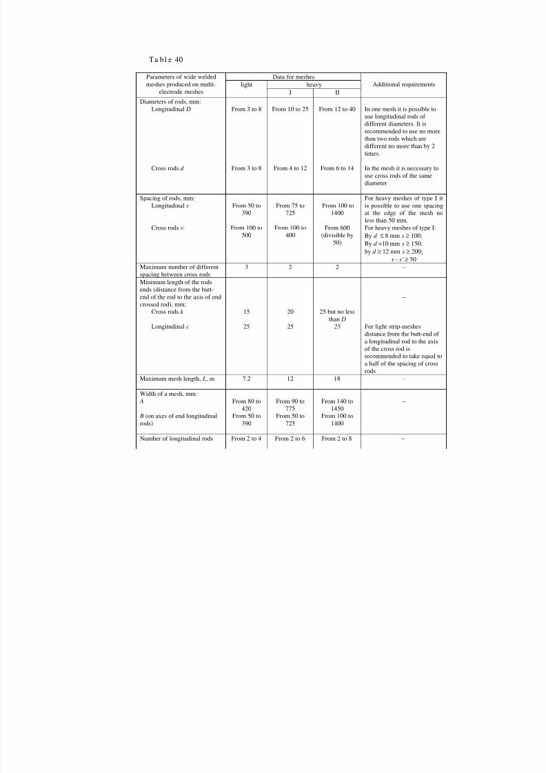
8/10/2019 Guidelines for Design of Concrete and r.c.structures_part2.ENG
http://slidepdf.com/reader/full/guidelines-for-design-of-concrete-and-rcstructurespart2eng 63/111
Ta b l e 40
Data for meshesheavy
Parameters of wide weldedmeshes produced on multi-
electrode mesheslight
I II
Additional requirements
Diameters of rods, mm:Longitudinal D
Cross rodsd
From 3 to 8
From 3 to 8
From 10 to 25
From 4 to 12
From 12 to 40
From 6 to 14
In one mesh it is possible touse longitudinal rods ofdifferent diameters. It isrecommended to use no morethan two rods which aredifferent no more than by 2times.
In the mesh it is necessary touse cross rods of the samediameter
Spacing of rods, mm:Longitudinalv
Cross rodss:
From 50 to390
From 100 to500
From 75 to725
From 100 to400
From 100 to1400
From 600(divisible by
50)
For heavy meshes of type I itis possible to use one spacingat the edge of the mesh noless than 50 mm.For heavy meshes of type I:Byd ≤ 8 mms ≥ 100;Byd =10 mms ≥ 150;byd ≥ 12 mms ≥ 200;
s - s' ≥ 50Maximum number of differentspacing between cross rods
3 2 2 –
Minimum length of the rodsends (distance from the butt-end of the rod to the axis of endcrossed rod), mm:
Cross rodsk
Longitudinalc
15
25
20
25
25 but no lessthan D
25
–
For light strip-meshesdistance from the butt-end ofa longitudinal rod to the axisof the cross rod isrecommended to take equal toa half of the spacing of crossrods
Maximum mesh length, L, m 7.2 12 18 –
Width of a mesh, mm: A
B (on axes of end longitudinalrods)
From 80 to420
From 50 to390
From 90 to775
From 50 to725
From 140 to1450
From 100 to1400
–
Number of longitudinal rods From 2 to 4 From 2 to 6 From 2 to 8 –

8/10/2019 Guidelines for Design of Concrete and r.c.structures_part2.ENG
http://slidepdf.com/reader/full/guidelines-for-design-of-concrete-and-rcstructurespart2eng 64/111
It is possible to take spacing of rods which are different of the values mentioned inTables 39 and 40 during design of details for a certain producing factory inconformity with the parameters of the equipment under conditions of unification ofthese spacing on the factory.
Welded meshes produced on multi-electrode machines must have rectangularcontours with rectangular cells. At the ends of rods there must not be any bendings,hooks or loops. They can be used only in compliance with the approval of theproducing plant.
5.23. Welded meshes whose constructive parameters do not allow the produce them onmulti-electrode machines must be designed in conformity with manufacturingcapabilities of single-point welding machines (Table 41).
5.24. Ready-mixed welded meshes as well as meshes and frameworks produced on multi-electrode and single-point machines can be used as finished reinforcing details or as asemi finished good which must be followed up (cutting of a mesh, making of holes,bending of a mesh to make a spatial framework and as and exception – welding ofadditional rods).
Additional rods can be welded by means of contact welding (Draft 94,а, б)considering instructions of Table 41, as well as electric arch welding by means oflongitudinal joints (Draft 94,в) considering requirements of Item 5.18.
Bending of a mesh is made according to Item 5.27.
Ta bl e 41
Parameters of welded meshes, produced onsingle-point welding machines Parameters valuesMaximum diameter of a less of welded rods,mm
For rods of both directionsВр-I,А-II, А-III, Ат -IIIС–25; by rods ofclassesВ-I, А-II–40. See also table38 (pos. 1 and 2)
Maximum width of welded meshes:recommendedallowable
5001000 +v1 (see draft for the table)
Maximum distances, mm, between axes of rodsof one direction by rods diameters, mm:Up to 10 40from 12 to 18 50from 20 to 25 6028 and 32 7036 and 40 80Minimum length of rods endsk to the axis ofend cross rod, mm
20, but no less than diameter of theend of the rod
Minimum angle between crossing welded rods,degree
30

8/10/2019 Guidelines for Design of Concrete and r.c.structures_part2.ENG
http://slidepdf.com/reader/full/guidelines-for-design-of-concrete-and-rcstructurespart2eng 65/111
Draft 94. Welding of an additional longitudinal rod to a welding meshа – initial mesh; б – welding of an additional rod near the main cross rod by means of point welding;в – thesame, close to the main rod by electric arch welding by longitudinal joints; 1 – main rod; 2 – additional rod; 3– electric arch welding (by lengthl ≤ 6 m rod 2 can be used only to the ends of the detail)
5.25. By reinforcement of sides of beams of variable height it is recommended:а) to use frameworks with groups of rods of one height by the slope no more than1:10 (Draft 95,а);b) to use separate rectangular frameworks (Draft 95,б) or rectangular meshes withthe following cutting along the inclined length (Draft 95,в) with a border rod in caseof need by the slope no more than 1:10.
By reinforcement of rectangular slabs it is recommended to use welding meshesproduced of rectangular ones as result of their cutting (Draft 95,г).
Spatial reinforcing frameworks
5.26. Reinforcement of rectangular elements (especially linear ones) must be designed as arule in form of spatial frameworks.
Spatial frameworks can be made as a whole detail or in form of spatial blocks used incombination with flat or bent meshes, as separate rods, etc.
Spatial frameworks must be designed as hard ones for their storage, transportationand to follow their design location by laying them into a form. Their rigidity must beprovided by means of installation of required bracings in form of rods, straps, etc.
Draft 95. Reinforcement of details of variable dimensionsа – sides of a beam by means of a mesh with groups of cross rods of the same length;б – the same, byseparate rectangular meshes;в – the same, by a rectangular mesh with cutting it along the inclined line andadding of border rods;г – by welded meshes for slabs of variable width, produced by cutting of a rectangularmesh
Embedded elements and tie-down details (hooks, pipes, etc) can be fixed to thespatial framework if required accuracy of the location is provided. If deviations fromthe design location can cause decrease of bearing capacity of embedded elements so iis necessary to fix these details to the form.
5.27. By forming of spatial frameworks using bent flat meshes it’s recommended to usebent meshes with contours according to types shown on Draft 96,а and produced byserial bending equipment. At the same time it is necessary to meet the followingrequirements:
- length of meshes must be no more than 6 m (by approval of a producing factorylength up to 9 m is possible);
- length of bent part (see Draft 97,е) – no less than 60 mm and no less than 8d ,- diameter of bent rods – no more than 12 mm (approved by producing factory – up to
32 mm).
Draft 96. Examples of shapes of bent welding meshes
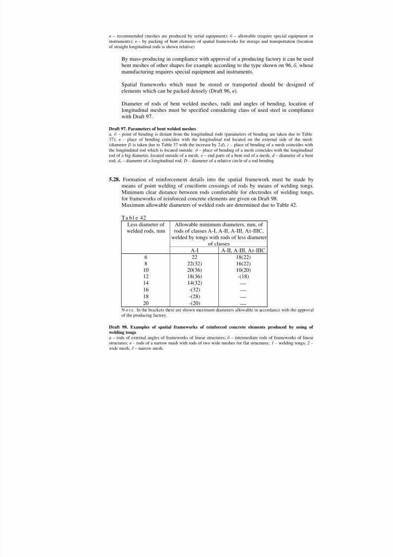
8/10/2019 Guidelines for Design of Concrete and r.c.structures_part2.ENG
http://slidepdf.com/reader/full/guidelines-for-design-of-concrete-and-rcstructurespart2eng 66/111
а – recommended (meshes are produced by serial equipment);б – allowable (require special equipment orinstruments);в – by packing of bent elements of spatial frameworks for storage and transportation (locationof straight longitudinal rods is shown relative)
By mass-producing in compliance with approval of a producing factory it can be usedbent meshes of other shapes for example according to the type shown on 96,б , whosemanufacturing requires special equipment and instruments.
Spatial frameworks which must be stored or transported should be designed ofelements which can be packed densely (Draft 96,в).
Diameter of rods of bent welded meshes, radii and angles of bending, location oflongitudinal meshes must be specified considering class of used steel in compliancewith Draft 97.
Draft 97. Parameters of bent welded meshesа , б – point of bending is distant from the longitudinal rods (parameters of bending are taken due to Table37); в – place of bending coincides with the longitudinal rod located on the external side of the mesh(diameter D is taken due to Table 37 with the increase by 2d ), г – place of bending of a mesh coincides withthe longitudinal rod which is located outside;д – place of bending of a mesh coincides with the longitudinalrod of a big diameter, located outside of a mesh; е – end parts of a bent rod of a mesh;d – diameter of a bentrod;d 1 – diameter of a longitudinal rod; D – diameter of a relative circle of a rod bending
5.28. Formation of reinforcement details into the spatial framework must be made bymeans of point welding of cruciform crossings of rods by means of welding tongs.Minimum clear distance between rods comfortable for electrodes of welding tongs,for frameworks of reinforced concrete elements are given on Draft 98.
Maximum allowable diameters of welded rods are determined due to Table 42.Ta bl e 42
Less diameter ofwelded rods, mm
Allowable minimum diameters, mm, ofrods of classesА-I, А-II,А-III,Ат -IIIС,
welded by tongs with rods of less diameterof classes
А-I А-II,А-III,Ат -IIIС 6 22 18(22)8 22(32) 16(22)10 20(36) 10(20)12 18(36) -(18)14 14(32) 16 -(32) 18 -(28) 20 -(20)
N o t e . In the brackets there are shown maximum diameters allowable in accordance with the approvalof the producing factory.
Draft 98. Examples of spatial frameworks of reinforced concrete elements produced by using ofwelding tongsа – rods of external angles of frameworks of linear structures;б – intermediate rods of frameworks of linear
structures;в – rods of a narrow mash with rods of two wide meshes for flat structures;1 – welding tongs;2 –wide mesh;3 – narrow mesh.
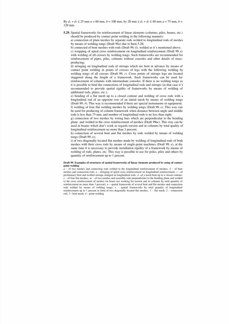
8/10/2019 Guidelines for Design of Concrete and r.c.structures_part2.ENG
http://slidepdf.com/reader/full/guidelines-for-design-of-concrete-and-rcstructurespart2eng 67/111
Byd 1 + d 2 ≤ 25 mma = 60 mm,b = 100 mm; by 28 mm≤ d 1 + d 2 ≤ 40 mmа = 75 mm,b =120 mm
5.29. Spatial frameworks for reinforcement of linear elements (columns, piles, beams, etc.)should be produced by contact point welding in the following manners:а) connection of plain meshes by separate rods welded to longitudinal rods of meshesby means of welding tongs (Draft 99a) due to Item 5.28;b) connected of bent meshes with rods (Draft 99,б ), welded as it’s mentioned above;c) wrapping of spiral cross reinforcement on longitudinal reinforcement (Draft 99,в)with welding of all crosses by welding tongs. Such frameworks are recommended forreinforcement of pipes, piles, columns without consoles and other details of mass-producing;d) stringing on longitudinal rods of stirrups which are bent in advance by means ofcontact point welding in points of crosses of legs with the following welding bywelding tongs of all crosses (Draft 99,г). Cross points of stirrups legs are locatedstaggered along the length of a framework. Such frameworks can be used forreinforcement of columns with intermediate consoles. If there is no welding tongs soit is possible to bind the connections of longitudinal rods and stirrups (in that case it’srecommended to provide spatial rigidity of frameworks by means of welding ofadditional rods, plates, etc.);e) bending of a flat mesh up to a closed contour and welding of cross rods with alongitudinal rod of an opposite row of an initial mesh by means of welding tongs(Draft 99,д). This way is recommended if there are special instruments or equipment;f) welding of four flat welding meshes by welding tongs (Draft 99,е). This way canbe used for producing of column framework when distance between angle and middlerods is less than 75 mm, and number of longitudinal rods is no less than eight;g) connection of two meshes by wiring bars which are perpendicular to the bendingplane and welded to the cross reinforcement of meshes (Draft 99ж ). This way can beused in beams which don’t work as regards torsion and in columns by total quality oflongitudinal reinforcement no more than 3 percent;h) connection of several bent and flat meshes by rods welded by means of weldingtongs (Draft 99,и);i) of two diagonally located flat meshes made by welding of longitudinal rods of bothmeshes with their cross rods by means of single-point machines (Draft 99,к), at thesame time it is necessary to provide installation rigidity of a framework by means ofwelding of rods, plates, etc. This way is possible to use for poles, piles and others byquantity of reinforcement up to 1 percent.
Draft 99. Examples of structures of spatial frameworks of linear elements produced by using of contactpoint weldingа – of two meshes and connecting rods welded to the longitudinal reinforcement of meshes;б – of bentmeshes and connection rods;в – stringing of spiral cross reinforcement on longitudinal reinforcement;г – ofpreliminary bent and welded stirrups stringed on longitudinal rods;д –of a mesh bent up to a closed contour;е – of four flat meshes;ж – of two meshes and assembly rods perpendicular to the bending plane and weldedto the cross reinforcement of meshes (in beans not working for torsion and in columns by total quantity ofreinforcement no more than 3 percent);и – spatial framework of several bent and flat meshes and connectionrods welded by means of welding tongs;к – spatial frameworks by total quantity of longitudinalreinforcement up to 1 percent in form of two diagonally located flat meshes;1 – flat mesh;2 – connectionrod;3 – bent mesh;4 – point welding

8/10/2019 Guidelines for Design of Concrete and r.c.structures_part2.ENG
http://slidepdf.com/reader/full/guidelines-for-design-of-concrete-and-rcstructurespart2eng 68/111
5.30. Spatial frameworks of linear elements can be produced without using of weldingpoint welding by means of the following methods:а) connection of meshes by brackets and by arch welding with stirrups (Draft 100,а).In columns, beams working for torsion as well as in compressed zone of beams withthe considered in the calculation working reinforcement the length of one-sidedwelding jointsl must be no less than 6d (whered – diameter of a stirrup), andinstallation connections – 3d ;b) connection of flat meshes by means of studs with bending of all crosses (Draft 100,б ), at the same time it is necessary to provide installation rigidity of the framework bywelding of rods, plates and others;c) connection of flat meshes to each other by means of arch welding of longitudinalrods (Draft 100,в) near all points of stirrups welding. Length of jointsl must be noless than 5d (whered – diameter of stirrups). Such connections can be used byquantity of compressed reinforcement in the section no more than 3 percent;d) of longitudinal rods and bent stirrups with binding of crosses (Draft 100,г) andconnection of rigidity elements (bound frameworks);e) of one or several bent or flat meshes and connection rods with diameters no morethan 6 mm by bending of longitudinal rods of meshes by ends of connection rodsmaking a closed loop by means of a bending instrument (Draft 100,д). This methodis recommended if there are special conductors providing safe fixing of frameworksIf there are compressed longitudinal rods so requirements to distances betweenconnection rods are the same as for distances for welded stirrups (see Item 5.59).
Due to great labor expenditures frameworks mentioned in the present Item can beused only as exceptions if there are no welding tongs.
Draft 100. Examples of spatial frameworks of linear elements produced without using contact pointweldingа – of two flat meshes and brackets welded to the cross reinforcement of meshes;б – of two flat meshesconnected by means of studs by binding of all crosses;в – of four flat meshes;г – of longitudinal rods andbent stirrups with binding of crosses;д – framework formed of one or several bent or flat meshes andconnecting rods by means of a bending instrument;1 – flat mesh;2 – a bracket or a stud;3 – cross rods of flatmeshes;4 – longitudinal meshes of flat rods;5 – arch welding; 6 – a bending instrument;7 – a bent mesh
5.31. Spatial frameworks for reinforcement of flat elements (slabs, wall panels, etc.) shouldbe produced in the following manner:а) connection of flat meshes of type «steps» by rods welded by welding tongs (Draft101,а);b) connection of meshes of type «steps» of one direction by means of the same flatmeshes of different direction and less height (Draft 101,б ). Connection of crosses ismade by tongs; binding is possible in case if there are no tongs.
To provide stability during installation in both mentioned cases flat meshes of type«steps» can be replaced by bent V-shaped meshes (Draft 101,в).
Spatial framework of ribbed slabs or panels is made of bent U-shaped meshes withwelding or binding to them of flat meshes of type «steps».
Draft 101. Examples of structures of spatial frameworks for reinforcement of flat elementsа – of flat meshes of type «steps» and connection rods;б – of flat meshes of type «steps» of one direction andthe same meshes of other direction and less height;в – of V-shaped meshes of the same direction and thesame meshes of other direction and less height

8/10/2019 Guidelines for Design of Concrete and r.c.structures_part2.ENG
http://slidepdf.com/reader/full/guidelines-for-design-of-concrete-and-rcstructurespart2eng 69/111
LOCATION OF REINFORCEMENT, ANCORAGE, BUTT-JOINTS
Protection layer of concrete
5.32. (5.4). Protection layer of concrete for main reinforcement must provide cooperationwork of reinforcement and concrete during all stages of the construction use as wellas protection against outside atmospheric, temperature and other effects.
5.33.(5.5, 5.6). Thickness of the protection layer must be as a rule no less than diameter ofa rod and no less than values mentioned in Table 43.
For prefabricated elements of heavy-weight concreteВ20 and more thickness of aprotection layer can be taken 5 mm less than diameter of a rod but no less than valuesgiven in Table 43.
For reinforced concrete slabs of heavy-weight concrete of classВ20 and moreproduced on factories in steel forms and protected from the above by toppingconcrete thickness of the protection layer for top reinforcement must be taken equalto 5 mm.
In one-layer structures of light and porous concrete of classВ7.5 and less thickness ofthe protection layer must be, mm:
- for longitudinal main reinforcement – no less than 20;- for outside wall panels (without stamped surface) – no less than 25;- for cross, constructive and distribution reinforcement – no less than 15.
Ta bl e 43
Kind of structure Functions ofreinforcement
Height (thickness)of the section, mm,
Thickness of the protectionlayer, mm, no less than
1. Slabs, walls,flanges of ribbed slabs
Longitudinalmain
Up to 100More than 100
1015
2. Beams, ribs ofslabs
The same Less than 250250 and more
1520
3. Columns, poles ′′ Any 20
3. Foundationbeams andprefabricatedfoundations
′′ ′′ 30
5. Solid foundations:- if there is concrete base Bottom
main′′ 35
- if there is no concretebase
The same ′′ 70
б. Any structure cross,distribution,constructive
Less than 250250 and more
1015

8/10/2019 Guidelines for Design of Concrete and r.c.structures_part2.ENG
http://slidepdf.com/reader/full/guidelines-for-design-of-concrete-and-rcstructurespart2eng 70/111
N o t e . For structures mentioned in positions 1-3 and for structures which are in contact with the ground values othickness of the protection layer are increased by 5 mm.
For prefabricated elements of heavy-weight concrete of classВ20 and more thicknessof the protection layer for longitudinal reinforcement can be taken 5 mm less than
diameter of the rod but no less than values mentioned in Table 43.For reinforced concrete slabs of heavy-weight concrete of classВ20 and more whichare produced on factories in metal forms and protected from the above by means oftopping concrete thickness of the protection layer for top reinforcement can be takenequal to 5 mm.
In one-layer structures made of light-weight and porous concrete of classВ7.5 andless thickness of the protection layer must be, mm:- For longitudinal main reinforcement – no less than 20;- For external wall panels (without textured layer) – no less than 25;
- For cross, constructive and distribution reinforcement – no less than 15.5.34(5.10). For hollow-core elements of ring or box-shaped section distance from rods of
longitudinal reinforcement to internal surface of concrete must meet requirements ofItem 5.33.
5.35. In bending, stretched and eccentric compressed by M l /N l > 0.3h, except foundations,thickness of the protection layer for stretched main reinforcement as a rule must notbe more than 50 mm. In the protection layer more than 50 mm thick it is necessary toinstall constructive reinforcement in form of meshes. At the same time section area oflongitudinal reinforcement of meshes must be no less than 0.05 As, pacing of crossreinforcement must be no more than the height of the element section and conform toinstructions of Item 5.54.
5.36. For structures which work in aggressive conditions thickness of the concreteprotection layer must be taken considering requirements of SNiP 2.03.11-85.
By specification of the concrete protection layer it is also necessary to followinstructions of SNiP 2.01.02-85.
5.37 (5.9). To install single-piece reinforcing rods, meshes, frameworks going along thewhole length or width of the element the ends of these rods must be distant from thesurface of the element if the length of the element is: up to 9 m – by 10 mm, up to 12m – by 15 mm, more than 12 m – by 20 mm.
Minimum distance between reinforcement rods
5.38 (5.11). Distances between reinforcement rods along the height and the width of theelement must provide cooperation work of reinforcement and concrete and must bespecified considering the convenience of installing it into a form and concreting.
By choosing of distances between rods in welded meshes as well as in flat and spatial
frameworks it is also necessary to consider technological requirements for design ofwelded reinforcement details mentioned in Items 5.22, 5.23 and 5.28.

8/10/2019 Guidelines for Design of Concrete and r.c.structures_part2.ENG
http://slidepdf.com/reader/full/guidelines-for-design-of-concrete-and-rcstructurespart2eng 71/111

8/10/2019 Guidelines for Design of Concrete and r.c.structures_part2.ENG
http://slidepdf.com/reader/full/guidelines-for-design-of-concrete-and-rcstructurespart2eng 72/111
5.44 (5.14). Longitudinal rods of stretched and compressed reinforcement must be brought
behind the normal to the longitudinal axis of the element section, where they areconsidered with total design resistance on the length no less thanlan , determined bythe following formula
( ) d R Rll an
b
sanlan
∆+= λ ω (316)
but no less thanlan = λ an d , where valuesω an ∆λ an and λ an , as well as possibleminimum valueslan are determined due to Table 44. At the same time plainreinforcement rods must end with hooks made due to Item 5.11, or have welded crossreinforcement along the length of embedment. To value Rb it is possible to insertcoefficients of concrete work conditions exceptγ b2.In elements of fine concrete of groupБ (see Item 2.1) valueslan, determined byformula (316), must be increased by 10d for stretched concrete and by 5d – forcompressed concrete.
Values of relative anchorage lengthλan = lan /d, determined by formula (316) fordifferent classes of concrete and reinforcement are given in Table 45.
T a b l e 44 (37)Parameters for determination of anchoragelengthlan of reinforcement without anchors
Periodic profile plainWorkconditions ofreinforcement
ω an ∆λ an λ an lan , мм
ω an ∆λ an λ an lan , мм
No less No less1.reinforcementembedment:а) stretchedreinforcementin stretchedconcrete
0,70 11 20 250 1,20 11 20 250
б) compressedor stretchedreinforcement
in compressedconcrete
0,50 8 12 200 0,80 8 15 200
2. overlappingofreinforcement:а) in stretchedconcrete
0,90 11 20 250 1,55 11 20 250
б) incompressedreinforcement
0,65 8 15 200 1,00 8 15 200

8/10/2019 Guidelines for Design of Concrete and r.c.structures_part2.ENG
http://slidepdf.com/reader/full/guidelines-for-design-of-concrete-and-rcstructurespart2eng 73/111
Ta bl e 45Relative length of reinforcement anchorageλan = lan /d by concrete of classesLocation of
reinforcement inconcrete
Reinforcementclass В7.5 В10 B12.5 B15 B20 B25 B30 B35 B40 B45 B50 B55 B60
1. stretched, A-I 72 58 48 42 34 30 27 25 23 22 21 21 20A-II 56 45 38 34 28 25 23 21 20 20 20 20 20
lan ≥ 250мм A-III 69 55 46 40 33 29 26 24 22 21 21 20 202. compressed, A-I 49 39 33 29 24 20 19 17 16 15 15 14 14
A-II 40 32 27 24 20 18 16 15 14 14 13 13 13lan ≥ 200мм A-III 50 40 33 29 24 21 19 17 16 15 15 15 14
In case when anchored rods are installed with the reserve on the section area againstthe required by the calculation as regards the strength with total design resistance, theanchorage lengthlan, calculated by formula (316) can be decreased by multiplying itby the ratio between the required due to the calculation and actual section area ofreinforcement.
If due to the calculation there are cracks caused by the concrete stretching along theanchored rods , so rods must be embedded into the compressed zone of concrete onthe lengthlan calculated by formula (316). At the same time height of compressedzone can be determined due to Item 4.16.
5.45. If it is impossible to meet requirements of Item 5.44 so it is necessary to take specialmeasures for anchorage of longitudinal rods:
а) special anchors in form of plates, washers, screws, angles, etc at the ends (Draft103). In that case area of contact of anchor with concrete must correspond thecondition of concrete strength to compression (se Item 3.109а), and thickness ofanchorage plate must be no less than 1/5 of the whole width (diameter) andcorrespond to welding conditions (see Table 52); length of the rod embedment mustbe determined by the calculation as regards chipping (see Item 3.106а) and must betaken no less than 10d ;
Draft 103. Anchorage of reinforcement by means of special anchorage at the ends of special anchorsа – welded plate;б – constricted plate;в – button-head;г – button-head with a washer;д – rod welded to anangle;е – a screw with a washer outside;ж – screws inside
b) bending of anchored rod at 90 degrees along the arch of the circle with the clearradius no less than 10d (1 – l l /lan ) [wherell – length of the straight part at thebeginning of embedment (Draft 104)], corresponding to recommendations of Table37; on the bent part there are installed additional stirrup against the unbending ofrods;
c) welding of anchoring cross rods on the length of embedment; in that caseanchorage lengthlan, determined due to Item 5.44, is decreased by the length
ss
wan A R
N ll =∆ , [where N w – see formula (82)]; if∆l ≥ 150 mm, so plain rods can be
made without hooks, at the same time valuelan, is not decreased.
Draft 104. Reinforcement anchorage by means of bending

8/10/2019 Guidelines for Design of Concrete and r.c.structures_part2.ENG
http://slidepdf.com/reader/full/guidelines-for-design-of-concrete-and-rcstructurespart2eng 74/111

8/10/2019 Guidelines for Design of Concrete and r.c.structures_part2.ENG
http://slidepdf.com/reader/full/guidelines-for-design-of-concrete-and-rcstructurespart2eng 75/111
Table 46
Relative length of the lap by concrete of classesLocation ofreinforcement
in concrete
Reinforcementclass
В12,5 B15 B20 B25 B30 B35 B40 B45 B50 B55 B60
stretched, Bp-I 56 49 40 34 30 27 26 24 23 23 22A-I 59 51 41 35 32 28 27 25 24 23 23
ll ≥ 250 mm A-II 46 40 33 28 26 24 22 21 21 20 20A-III 56 49 40 34 30 27 26 24 23 23 22
compressed, Bp-I 41 35 29 24 22 20 19 18 17 17 16A-I 39 26 28 24 21 19 18 17 16 16 16
ll ≥ 200 mm A-II 33 29 24 21 19 17 16 15 15 15 15A-III 41 35 29 24 22 20 19 18 17 17 16
5.49 (5.39). Joints of welded meshes and frameworks as well as of stretched rods of boundframeworks and meshes without welding must locate as a rule in stagger. At the same
time section area of main reinforcement connected in one place or at the distance lessthan overlapping lengthl, must be no more than 50 percent of total section area ofstretched reinforcement by rods of periodic profile and no more than 25 percent – byplain rods.
Displacement of rods located in different places must be no less than 1.5ll (Draft 106,б ).
Connection of separate rods, welded meshes and frameworks without stagger ispossible by constructive reinforcement (without calculation), as well as on those partswhere reinforcement is used no more than 50 percent.
In element cross section reinforcement joints must be located symmetrically.
5.50. By rebate joints connected rods must be located as close to each other as it’s possible;clear distance between connected rods must be no more than 4d , that means0 ≤ e ≤ 4d (Draft 106,a).
Draft 106. Location of rods connected with overlapping and jointsа – location of rod in the joint;б – location of joints
Neighbor rebate joints must not be located too close to each other. Clear distance
between them must be no less than 2d (d – diameter of connected rods) and no lessthan 30 mm (see Draft 106,б ).
5.51 (5.40) Joints of welded meshes in the direction of main reinforcement of plain hot-rolled steel of classА-I must be made so that in each of welded in the stretched zonemeshes there were located no less than two cross rods welded to all longitudinal rodsof meshes on the length of overlapping (Draft 107).
Draft 107. Rebate joints of welded meshes in the direction of main reinforcement made of plain rodsа – by location of distributed rods in one plane;б , в – the same in different planes

8/10/2019 Guidelines for Design of Concrete and r.c.structures_part2.ENG
http://slidepdf.com/reader/full/guidelines-for-design-of-concrete-and-rcstructurespart2eng 76/111
Length of overlapping of welded meshes with plain main reinforcement if there aretwo welded anchor rods on the length of overlapping must be no less than valuell,calculated due to Item 5.48.
The same types of joints are used for rebated joints of welded frameworks with one-side location of main rods of all types of steel.Joints of welded meshes in the direction of main reinforcement of classА-II, А-IIIand Ат -IIIС are made without cross rods within the joint in one or both connectedmeshes (Draft 108,а , б ); at the same time the overlapping lengthl is taken incompliance with item 5.48.
By welding of cross anchor rods to main rods of periodic profile of welded meshesand frameworks (Draft 108,в, г) length of overlapping determined in compliancewith Item 5.48, can be decreased by 5d for one cross anchor rod, by 8d – for twocross anchor rods.
In all cases length of overlapping must be no less than 15d in stretched concrete and10d – in compressed concrete.
If diameter of main rods connected with overlapping in the stretched zone is more
than 10 mm and distance between rods is less than valuebt
s
R
Rd 300
(where d –
minimum diameter of connected rods, mm), in places of joints it is necessary toinstall additional cross reinforcement in form of stirrups or suspension in form of U-shaped welded meshes brought into the compressed zone. At the same time sectionarea of additional cross reinforcement installed within the joint must be no less than
sw
ss R
R A4.0 (where А , – section area of all connected rods).
By rebate joints of welded frameworks in beams on the length of the jointindependently on the diameter of main rods it is necessary to install additionalreinforcement in form of stirrups or U-shaped welded meshes. At the same timespacing of additional cross rods within the joint must be no more than 5d (d – theleast diameter of longitudinal main rods).
Draft 108. Rebate joints of welded meshes in the direction of main reinforcement of periodic profileа – without anchor cross rods on two meshes;б – the same on one of meshes;в – by one anchor rod;г – bytwo anchor rods
5.52 (5.41). Joints of welded meshes in not main direction are made with overlapping(counting between axes of end working rods of the mesh):by diameter of distributed reinforcement up to 4 mm – by 50 mm (Draft 109,a , б )the same more than 4 mm – by 100 mm, (Draft 109,в, г)
By diameter of main reinforcement 16 mm and more welded meshes in not maindirection can be installed close to each other, covering the joints by means of specialcovering meshes installed with overlapping to each side no less than 15d ofdistributed reinforcement and no less than 100 mm (Draft 109, д).
8/10/2019 Guidelines for Design of Concrete and r.c.structures_part2.ENG
http://slidepdf.com/reader/full/guidelines-for-design-of-concrete-and-rcstructurespart2eng 77/111

8/10/2019 Guidelines for Design of Concrete and r.c.structures_part2.ENG
http://slidepdf.com/reader/full/guidelines-for-design-of-concrete-and-rcstructurespart2eng 78/111
Table 47(38)Work condition ofreinforcement
Minimum section area oflongitudinal reinforcement inreinforced concrete elements,percent of section area ofconcrete1. ReinforcementS in bending
as well as in eccentric stretchedelements by location oflongitudinal force beyond theworking height of the section
0,05
2. Reinforcement S , S' ineccentric stretched elements bylocation of longitudinal forcebetween reinforcementS andS'
0,05
3. Reinforcement S , S' ineccentric compressed elementsby:a) lo /i < 17 (for rectangularsections – bylo /h < 5)
0,05
b) 17≤ lo /i ≤ 35 (5≤ lo /h ≤ 10) 0,10c) 35 <lo /i ≤ 83 (10 <lo /h ≤ 24) 0,20d) lo /i > 83 (lo /h > 24) 0,25
Note. Minimum section area of reinforcement given in Table 47 belongs to the section area of concrete equal tothe product of the width of rectangular section or width of the rib of T-section (I-section)b by the main height ofthe sectionho. In elements with longitudinal reinforcement spread evenly along the section contour, as well as incentral stretched elements minimum area of all longitudinal reinforcement belongs to the total section area ofconcrete and must be taken two times more than values mentioned in Table 47.
Reinforcement of compressed elements
LONGITUDINAL REINFORCEMENT
5.56 (5.17). Diameter, mm, of longitudinal rods of compressed elements must be no morethan:for heavy-weight and fine concrete of class less thanВ25 ………………….. 40for light-weight and porous concrete of classes:
В12,5 and less …………………………………………………………………16В15 –В25 ……………………………………………………………………..25В30 and more ………………………………………………………………….40
For high-capacity columns of heavy-weight concrete of classВ20 and more and bycorresponding equipment for cutting, welding and other it is possible to use rods withdiameter more than 40 mm.
Diameter of longitudinal rods of eccentric compressed elements of solid structuresmust be no less than 12 mm. In columns with the dimension of the less side of thesection 250 and more diameters of longitudinal rods should be no less than 16 mm.
5.57(5.18). In linear eccentric compressed elements distances between axes of rods oflongitudinal reinforcement must be taken in the direction perpendicular to the

8/10/2019 Guidelines for Design of Concrete and r.c.structures_part2.ENG
http://slidepdf.com/reader/full/guidelines-for-design-of-concrete-and-rcstructurespart2eng 79/111
bending plate no more than 400 mm, and in the direction of the bending plane – nomore than 500 mm.
If distances between axes of main rods in the direction of the bending plane are morethan 500 mm so it is necessary to install construction reinforcement with diameter noless than 12 mm, so that distance between longitudinal rods was no more than 400mm.
5.58(5.19). In eccentric compressed elements whose bearing capacity is used less than by50 percent as well in elements with elasticitylo /i < 17 (for example in columnpockets) where compressed reinforcement is not required by the calculation, andquantity of stretched reinforcement is no more than 0.3 percent it is possible not toinstall longitudinal and cross reinforcement which is required due to Items 5.54, 5.575.59 and 5.60 along the surfaces parallel to the bending plane. At the same timereinforcement along the surfaces perpendicular to the bending plane is made bywelded frameworks and meshes with the concrete protection layer no less than 50mm and no less than two diameters of longitudinal reinforcement.
CROSS REINFORCEMENT
5.59 (5.22). In eccentric compressed linear elements by considered in the calculationcompressed longitudinal reinforcement to prevent its uplift the stirrups must beinstalled at distances no more than 500 mm and no more than: by bound frameworks– 15d , by welded frameworks – 20d (d – minimum diameter of compressedlongitudinal rods).
Distances between stirrups of eccentric compressed elements in points of rebate jointsof main reinforcement without welding must be no more than 10d .
If congestion of the element by required by the calculation compressed longitudinalreinforcementS' is more than 1.5 percent so stirrups must be installed at distances nomore than 10d and no more than 300 mm.
Cross reinforcement structure mutt provide fixing of compressed rods to prevent theirlateral uplift in any direction.
During control how requirements of the present item are met longitudinal compressed
rods which are not considered by the calculation must not be taken into account, ifdiameter of these rods is no more than 12 mm and no more than a half of cracks ofconcrete protection layer.
Note. By high-strength compressed reinforcement of class A-IV and more distances between stirrupsmust be no more than 400 mm and for bound frameworks – no more than 12d , for welded frameworks– no more than 15d .
5.60 (5.23). By reinforcement of eccentric compressed elements by flat welded frameworkstwo end frameworks (located at opposite surfaces) must be connected to each other toform a spatial framework. For that at the surfaces of elements normal to the plane offrameworks it is necessary to install cross rods welded by contact point welding toangle longitudinal rods of frameworks, or studs connecting these rods at the samedistances like cross rods of plane frameworks.

8/10/2019 Guidelines for Design of Concrete and r.c.structures_part2.ENG
http://slidepdf.com/reader/full/guidelines-for-design-of-concrete-and-rcstructurespart2eng 80/111
If end plane frameworks have intermediate longitudinal rods so these rods must beconnected with longitudinal rods located at opposite surfaces by means of studs, noless than next nearest and no less than each 400 mm along the width of the elementsurface. It is possible not to install studs if the width of the present surface of theelement is no more than 500 mm and number of longitudinal rods at this surface isany more than four. It is also possible not to install studs at intermediate rods whichare distant from the angle ones no farther than 15d w, independently on the width ofthe element and number of rods.By larger dimensions of the element section it is recommended to install intermediateflat welded meshes (Draft 110,a).
Draft 110. Structure of spatial frameworks in compressed elementsа – welded;б – bound;1 – connection rods;2 – plane welded frameworks;3 – stirrup;4 – intermediate planeframework;5 – a stirrup
Structure of bound stirrups in eccentric compressed elements must be so thatlongitudinal rods (at leas every second one) were located at the bending point ofstirrups, and this bendings – at the distance no more than 400 mm along the width ofthe element surface. By width of the surface no more than 400 mm and number oflongitudinal rods at this surface no more than four it is possible to bind alllongitudinal rods by one stirrup (Draft 110,б ). Independently on the width of thesurface and number of rods it is possible not to install intermediate rods in stirrupsbendings if these rods are distant from angle rods no more than 15d w. At the ends ofbound stirrups it is necessary to install hooks.
5.61 (5.25). Diameter of stirrups of eccentric compressed elements must be taken no less
than 0.25d (d – maximum diameter of longitudinal rods), and in bound frameworksno less than 5 mm.
Reinforcement of bending elements
LONGITUDINAL REINFORCEMENT
5.62 (5.20). Beams and ribs 150 and less mm wide (Draft 111), working for bending can bereinforced by one flat vertical framework, and more than 150 wide ones and by grealoads they must be reinforced by several vertical meshes (frameworks).In beams more than 150 mm wide number of longitudinal main rods brought behindthe surface of the support must be no less than two. In ribs of prefabricated panels,decks, multiribbed plates and other 150 and less mm wide it is possible to bring onelongitudinal rod to the support.
Draft 111. Reinforcement of beams by plain welded meshes1 – connecting rods;2 – flat welded frameworks
5.63 (5.21). In bending elements by the height of the section more than 700 mm at lateralsurfaces it is necessary to install constructive longitudinal rods with the distancebetween them along the height no more than 400мм and with the section area no lessthan 0.1 percent of the concrete section area which has the dimensions equal to thedistance between these rods along the height, along the width – to a half of the widthof the element rib, but no more than 200 mm (Draft 112).
8/10/2019 Guidelines for Design of Concrete and r.c.structures_part2.ENG
http://slidepdf.com/reader/full/guidelines-for-design-of-concrete-and-rcstructurespart2eng 81/111
Draft 112. Installation of constructive longitudinal reinforcement along the height of the beam section
5.64 (5.20). Distance between axes of main rods in the middle part of the slab span andabove the support (on the top) must be no more than 200 mm by the plate width up to
150 mm and no more than 1.5h by the height of the slab more than 150 mm (h –height of the slab).
In slabs more than 350 mm wide distance between axes of main rods can bedecreased up to 600 mm.
In solid plates distance between rods brought to the surface of the support must be nomore than 400 mm, at the same time section area of these rods per 1 m of the slabwidth must be no less than 1/3 of the section area of rods in the span, determined bythe calculation due to maximum bending moment.
In hollow-core decks distance between axes of main rods can be decreased due tolocation of hollows in the section, but no more than up to 2h.
By reinforcement of continuous slabs by means of welded roll meshes it is possiblenear intermediate rods to move all bottom rods to the top zone.
Continuous slabs no more than 80 mm thick can be reinforced by means of single flameshes without bending.
5.65. If main reinforcement of the slab goes parallel to the rib so perpendicular to it it’snecessary to install additional reinforcement with the section no less than 1/3 ofmaximum section of main reinforcement of the slab in the span and bring it in theslab to each side of the rib at the length no less than 1/4 of design span of the slab.
If main reinforcement of the slab above the support goes perpendicular to the rib, it isnecessary to break it no closer than at the distance 1/4 of design span of the slab fromthe surface of the rib (черт . 113).
Draft 113. Reinforcement of support parts of slabs monolithically connected with beams1 – main span reinforcement of the slab;2 – main reinforcement of the slab above the span;l – design span ofthe slab
In beam slabs section area of distributed reinforcement per width unit of the slab musbe no less than 2 percent of the section area of main reinforcement per width unit ofthe slab in the point of maximum bending moment.
Distance between rods of distributed reinforcement of beam slabs must be no morethan 600 mm.
CROSS AND DIAGONAL REINFORCEMENT
5.66 (5.26). In beam structures more than 150 mm high, as well as in hollow-core slabs (orsimilar multi-ribbed structures) more than 300 mm high it is necessary to install crossreinforcement according to instructions of Item 5.69.

8/10/2019 Guidelines for Design of Concrete and r.c.structures_part2.ENG
http://slidepdf.com/reader/full/guidelines-for-design-of-concrete-and-rcstructurespart2eng 82/111
In solid plates independently on the height, in hollow-core plates (or similar multi-ribbed structures) 300 and less mm high and in beam structures 150 and less mm highit is possible not to install cross reinforcement, at the same time the requirements ofthe calculation due to Items 3.40 and 3.41 must be met.
5.67. To prevent lateral uplift of rods if compressed zone it is necessary to install crossreinforcement in compliance with requirements of Item 5.59.
5.68 (5.25). Diameter of stirrups in bound frameworks of bending elements must be takenno less than, mm:by the section height, equal or less than 800 mm 6the same more than 800 mm 8
The ratio between diameters of cross and longitudinal rods in welded meshesdetermined due to the welding conditions is taken in conformity with positions 1 and2 of Table 38.
5.69 (5.27). Cross reinforcement in beams and slabs structures mentioned in Item 5.66 isinstalled in support parts by distributed loads equal to 1/4 of the span, and by pointloads – to the distance from the support to the nearest load but no less than 1/4 of thespan with spacing:by section height of the elementh, equal or less than 450 mm no more thanh /2
and no more than 150 mmby section height of the element h more than 450 mm no more thanh /3
and no more than 500 mm
On the other part of the span by section height of the element h more than 300 mm itis installed cross reinforcement with spacing no more than 3/4h and no more than 500mm.
For ribbed plates in the middle part of the span if requirements of Item 3.40 are metso mentioned above instructions are not to be taken into account.
5.70. To provide anchorage of cross reinforcement of bending elements the connections oflongitudinal and cross rods in welded frameworks must be made in compliance withrequirements of positions 1 and 2 of Table 38. In bound frameworks the stirrups mustbe designed so that at the places of their bending there were longitudinal rods (Draft114). At the same time in welded as well as in bound frameworks diameter of
longitudinal rods must be no less than 0.8 of diameter of cross rods.By bound reinforcement in intermediate (middle) beams of T-section monolithicallyconnected with a slab, it’s recommended to install open stirrups.
Draft 114. Structure of stirrups of bound frameworks of beams
5.71. Bent rods of reinforcement must be installed in bending elements by theirreinforcement by bound frameworks. The rods must be bent along the arch withradius no less than 10d (Draft 115). In bending elements at the ends of bent rods it isnecessary to make straight parts no less than 0,8lan long taken according to
instructions of Item 5.44, but no less than 20d in stretched zone and 10d – incompressed zone.

8/10/2019 Guidelines for Design of Concrete and r.c.structures_part2.ENG
http://slidepdf.com/reader/full/guidelines-for-design-of-concrete-and-rcstructurespart2eng 83/111
Draft 115. Structure of reinforcement bend
Straight parts of bent pain rods must end with hooks.
Beginning of bend in stretched zone must be distant from the normal, in which bentrod is used due to the calculation, no less than by 0,5ho, and the end of bend must belocated no closer than that normal section where bend is not required by thecalculation (Draft 116).
Distance from the surface of free support to the top end of the first bend (countingfrom the support) must be no more than 50 mm.
Draft 116. Location of bends, determined due to the moments diagram in the beam1 – beginning of bend in the stretched zone А; 2 – the same in zone Б ; 3 – section where rodа is not requireddue to the calculation of zone А; 4 – section where rodб is not required due to the calculation of zone Б ; 5 –curve of bending moments; 6 – diagram of materials
5.72. Angle of slope of bendings to the longitudinal axis of the element must be taken as arule 45 degrees. In beams more than 800 mm high and in beams-walls it is possible toincrease angle of slope of bendings up to 60 degrees and in low beams and slabs – todecrease up to 30 degrees.
Rods with bends should be located at the distance no less than 2d from lateralsurfaces of the element (d – diameter of bent rod). It is not recommended to bend therods located directly at lateral surfaces.
Rods bends should be located symmetrically relating to longitudinal axis of the beam.Use of bends in form of „floating" rods (Draft 117) is not allowable.
Draft 117. „Floating" rod
Reinforcement of elements working for bending for torsion
5.73 (5.31). In elements working for bending with torsion bound stirrups must be closedwith reliable anchorage at the ends, and for welded frameworks all lateral rods ofboth directions must be welded to angle longitudinal rods and form closed circle.
Spatial frameworks should be designed considering requirements of Items 5.28,5.29а-е and 5.30.
Distances between cross rods located at the surfaces parallel to the bending planemust correspond to requirements of Item 5.69. Distances between cross rods locatedat the surfaces normal to the bending plane must be no more than the width of theelement sectionb. At surfaces compressed by bending byТ ≤ М /5 it is possible toincrease the distances between cross rods taking them due to Items 5.54 and 5.59.
Requirements of the present Item are applied to end beams to which secondary beamor slabs join only from one side, as well as middle beams to which design loadstransferred from adjoining to them spans are different and differ more than 2 times.

8/10/2019 Guidelines for Design of Concrete and r.c.structures_part2.ENG
http://slidepdf.com/reader/full/guidelines-for-design-of-concrete-and-rcstructurespart2eng 84/111
Special cases of reinforcement
REINFORCEMENT OF DETAILS WITH HOLES
5.74 (5.50). Big holes in reinforced concrete slabs, panels and others must have additionalreinforcement with the section no less than section of main reinforcement (of thesame direction), with is required by the calculation as for a solid one. Replacingreinforcement must be brought behind the edges of a hole at the length no less thanoverlapping lengthll, determined due to Item 5.48.
Holes in sides of elements must have round form and edges of holes must bereinforced.
REINFORCEMENT OF SLABS IN THE PUNCHING ZONE
5.75 (5.29). Cross reinforcement in slabs in a punching zone is installed with the spacingno more than 1/3h and no more than 200 mm, at the same time the width of the zoneof cross reinforcement installation must be no less than 1,5h (h – thickness of a slab).
Anchorage of the mentioned above reinforcement must correspond to requirements oItem 5.70.
DESIGN OF SHORT CONSOLES
5.76. Short consoles can be of constant and variable height with enlargement to theembedment place.
Consoles of variable height should be designed by great loads.
5.77 (5.30). Cross reinforcement of cross consoles should be made:- by h ≤ 2.5с – by stirrups inclined at the angle 45 degrees (Draft 118,а);- by h > 2.5с – by horizontal stirrups (Draft 118,б ).
Draft 118. Short consoles of columns with stirrupsа – inclined;б – horizontal
In all cases spacing of stirrups must be no more thanh /4 and no more than 150 mm (h – height of a console). By Limited height of the console it is possible to use hardreinforcement (Draft 119).
Draft 119. Short console with hard reinforcement
CONFINEMENT REINFORCEMENT
5.78 (5.24). Confinement reinforcement prevents cross expansion of concrete, due to thatconcrete strength by longitudinal compression is increased.
Confinement reinforcement is used in form of cross welded meshes (Draft 120) orspirals (rings) (Draft 121).
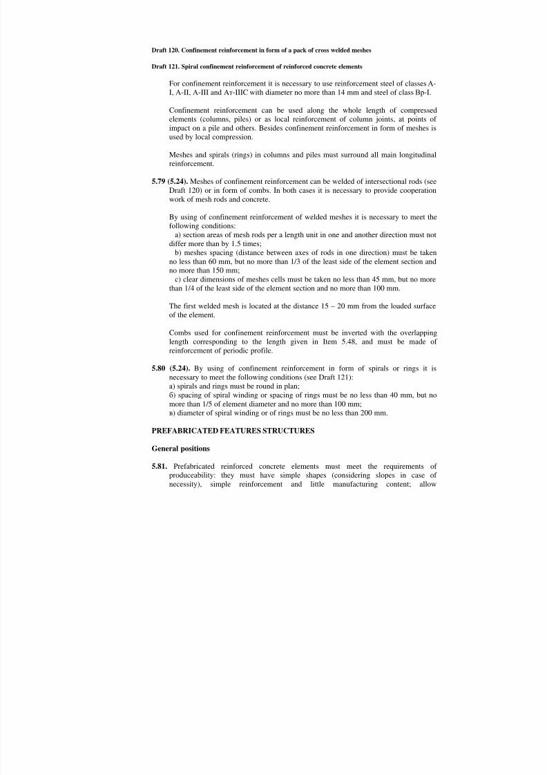
8/10/2019 Guidelines for Design of Concrete and r.c.structures_part2.ENG
http://slidepdf.com/reader/full/guidelines-for-design-of-concrete-and-rcstructurespart2eng 85/111
Draft 120. Confinement reinforcement in form of a pack of cross welded meshes
Draft 121. Spiral confinement reinforcement of reinforced concrete elements
For confinement reinforcement it is necessary to use reinforcement steel of classesА-
I, А-II,А-III and Aт-IIIC with diameter no more than 14 mm and steel of classВр-I.Confinement reinforcement can be used along the whole length of compressedelements (columns, piles) or as local reinforcement of column joints, at points ofimpact on a pile and others. Besides confinement reinforcement in form of meshes isused by local compression.
Meshes and spirals (rings) in columns and piles must surround all main longitudinalreinforcement.
5.79 (5.24). Meshes of confinement reinforcement can be welded of intersectional rods (see
Draft 120) or in form of combs. In both cases it is necessary to provide cooperationwork of mesh rods and concrete.
By using of confinement reinforcement of welded meshes it is necessary to meet thefollowing conditions:
а) section areas of mesh rods per a length unit in one and another direction must notdiffer more than by 1.5 times;
b) meshes spacing (distance between axes of rods in one direction) must be takenno less than 60 mm, but no more than 1/3 of the least side of the element section andno more than 150 mm;
c) clear dimensions of meshes cells must be taken no less than 45 mm, but no morethan 1/4 of the least side of the element section and no more than 100 mm.
The first welded mesh is located at the distance 15 – 20 mm from the loaded surfaceof the element.
Combs used for confinement reinforcement must be inverted with the overlappinglength corresponding to the length given in Item 5.48, and must be made ofreinforcement of periodic profile.
5.80 (5.24). By using of confinement reinforcement in form of spirals or rings it isnecessary to meet the following conditions (see Draft 121):а) spirals and rings must be round in plan;б) spacing of spiral winding or spacing of rings must be no less than 40 mm, but nomore than 1/5 of element diameter and no more than 100 mm;в) diameter of spiral winding or of rings must be no less than 200 mm.
PREFABRICATED FEATURES STRUCTURES
General positions
5.81. Prefabricated reinforced concrete elements must meet the requirements of
produceability: they must have simple shapes (considering slopes in case ofnecessity), simple reinforcement and little manufacturing content; allow

8/10/2019 Guidelines for Design of Concrete and r.c.structures_part2.ENG
http://slidepdf.com/reader/full/guidelines-for-design-of-concrete-and-rcstructurespart2eng 86/111
mechanization and automatization of production, fast production, as well astransportable and convenient for installation.
Reinforced concrete elements must be designed as a rule for production in formswithout following concreting or assembly of separate items before installation.
5.82. Dimensions and shapes of prefabricated elements must conform to requirements ofItems 5.5 – 5.8.
5.83. Prefabricated reinforced concrete elements should be designed so that it was possibleto produce them in solid forms.
If production of an element in a solid form is impossible so it is recommended todesign as big part as it’s possible as a solid one.
5.84. Ribs in sides of beams should be designed only by great point loads or if it isnecessary to provide the stability of the side.
5.85. Requirements for accuracy of manufacturing of reinforced concrete elements must bespecified according to the analysis of their adjoining type with other elements. So, forexample, by concreting of joints some deviations from nominal dimensions areallowable as they are to be balanced during concreting.
Joints of elements of prefabricated structures
5.86 (5.42). By joins of reinforced concrete elements of prefabricated structures the forcesfrom one element to another are transferred through the abutting main reinforcementsteel embedded elements, filled by concrete or mortar joints, concrete keys or (forcompressed elements) directly through concrete surfaces of adjoining elements.
5.87 (5.43). Fixed joints of prefabricated structures must be monolithed by filling of jointsbetween elements by concrete. If during manufacturing of elements the surfaces areadjusted to each other (for example by using of the butt end of one of the elements isused as a framework for the butt end of the other element), so by transferring of onlycompression force through the joint it is possible to make dry joints.
5.88. It is necessary to make such constructive decisions which provide simplicity of
manufacturing of joint details (embedded elements, meshes and other), theirassembly, fixing in the form, forming of the detail as well as installation andconnecting of reinforced concrete prefabricated elements.
5.89 (5.44). Joints of elements which take stretching forces must be made:а) by welding of steel embedded elements;b) welding of reinforcement connecting bars;c) agglutination of elements by constructive polymer mortars using connection derailof rod reinforcement;d) monolithing of connecting rods with overlapping.
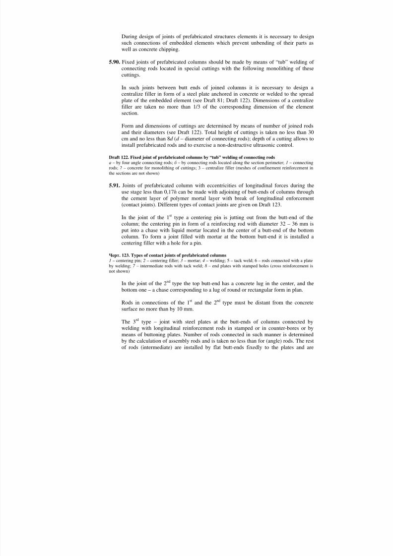
8/10/2019 Guidelines for Design of Concrete and r.c.structures_part2.ENG
http://slidepdf.com/reader/full/guidelines-for-design-of-concrete-and-rcstructurespart2eng 87/111
During design of joints of prefabricated structures elements it is necessary to designsuch connections of embedded elements which prevent unbending of their parts aswell as concrete chipping.
5.90. Fixed joints of prefabricated columns should be made by means of “tub” welding ofconnecting rods located in special cuttings with the following monolithing of thesecuttings.
In such joints between butt ends of joined columns it is necessary to design acentralize filler in form of a steel plate anchored in concrete or welded to the spreadplate of the embedded element (see Draft 81; Draft 122). Dimensions of a centralizefiller are taken no more than 1/3 of the corresponding dimension of the elementsection.
Form and dimensions of cuttings are determined by means of number of joined rodsand their diameters (see Draft 122). Total height of cuttings is taken no less than 30cm and no less than 8d (d – diameter of connecting rods); depth of a cutting allows toinstall prefabricated rods and to exercise a non-destructive ultrasonic control.
Draft 122. Fixed joint of prefabricated columns by “tub” welding of connecting rodsа – by four angle connecting rods;б – by connecting rods located along the section perimeter;1 – connectingrods;2 – concrete for monolithing of cuttings; 3 – centralize filler (meshes of confinement reinforcement inthe sections are not shown)
5.91. Joints of prefabricated column with eccentricities of longitudinal forces during theuse stage less than 0,17h can be made with adjoining of butt-ends of columns throughthe cement layer of polymer mortal layer with break of longitudinal enforcement
(contact joints). Different types of contact joints are given on Draft 123.In the joint of the 1st type a centering pin is jutting out from the butt-end of thecolumn; the centering pin in form of a reinforcing rod with diameter 32 – 36 mm isput into a chase with liquid mortar located in the center of a butt-end of the bottomcolumn. To form a joint filled with mortar at the bottom butt-end it is installed acentering filler with a hole for a pin.
Черт . 123. Types of contact joints of prefabricated columns1 – centering pin;2 – centering filler;3 – mortar;4 – welding; 5 – tack weld; 6 – rods connected with a plateby welding;7 – intermediate rods with tack weld;8 – end plates with stamped holes (cross reinforcement isnot shown)
In the joint of the 2nd type the top butt-end has a concrete lug in the center, and thebottom one – a chase corresponding to a lug of round or rectangular form in plan.
Rods in connections of the 1st and the 2nd type must be distant from the concretesurface no more than by 10 mm.
The 3rd type – joint with steel plates at the butt-ends of columns connected bywelding with longitudinal reinforcement rods in stamped or in counter-bores or bymeans of buttoning plates. Number of rods connected in such manner is determined
by the calculation of assembly rods and is taken no less than for (angle) rods. The resof rods (intermediate) are installed by flat butt-ends fixedly to the plates and are

8/10/2019 Guidelines for Design of Concrete and r.c.structures_part2.ENG
http://slidepdf.com/reader/full/guidelines-for-design-of-concrete-and-rcstructurespart2eng 88/111
welded to them by arch welding. After installation of columns end plates areconnected by long welded joints along the perimeter or angles of the section.
Thickness of end plates is taken no less than: by connection of reinforcement with theplate in stamped holes or fixedly – 0.25d a and 6 mm; in counter bores – 0.35d a and 12mm (d a – diameter of longitudinal rods required by the calculation). If in the columnshaft there is installed considered in the calculation confinement reinforcement sothickness of the plates should be increased by 2 mm.
5.92 (5.24). At the end parts of connected plates, if special reinforcement is not provided(iron ring, embedded elements), it is necessary to install confinement reinforcementmeshes in accordance with the instructions of Items 5.78 and 5.79 – no less than fourmeshes on the length (counting from the butt-end of the element) no less than 20d , iflongitudinal reinforcement is made of plain rods, and no less than 10d – of periodicprofile rods (d – maximum diameter of longitudinal reinforcement).
Saturation factor of confinement reinforcement µ xy (see Item 3.57) is taken no lessthan 0.0125.
For joints mentioned in Item 5.90, in case of necessity monolithing concrete in zoneof cuttings can be reinforced by welded meshes. In zone of cuttings there are installedone or two closed stirrups which bend connection rods.
By contact joints of the 3rd type (see Item 5.91) in end parts of joined columns it ispossible not to install meshes of confinement reinforcement, if they are not designedin the columns. But at the length 10d a of end part it is necessary to install crossreinforcement (stirrups, meshes) of the same structure like in the column shaft takingits spacing no more than: 0.25 of maximum section dimension; 0.6 of spacing of crossreinforcement in the column shaft; 80 mm.
5.93. Dimensions of welded joints made by produce of steel embedded elements and bytheir connection during installation in the joints of prefabricated elements must becalculated in compliance with the requirements of SNiP II-23-81. Alternative ofwelding method of connecting rods and constructive elements of these connectionsshould be provided due to Items 5.15 – 5.17, as well as due to state standards andnormative documents for welding technologies.
During design of welded joints and embedded elements it is necessary to use weldingmethods which don’t cause warping of steel details joints.
5.94 (5.51). During design of prefabricated floors elements it is necessary to design the joints between them which are filled with concrete. Width of joints is taken due tocondition of their qualitative filling and must be taken no less than 20 mm forelements with the section height 250 mm and no less than 30 mm – for elements withgreat height. At the same time it is necessary to provide the possibility to arrange to joined reinforcement or embedded elements and to provide their qualitative welding.
Class of concrete for filling of joints which transfer design forces is taken incompliance with Item 2.4.

8/10/2019 Guidelines for Design of Concrete and r.c.structures_part2.ENG
http://slidepdf.com/reader/full/guidelines-for-design-of-concrete-and-rcstructurespart2eng 89/111
For concreting of difficult-to-access or difficult-to-control points of the joint it isrecommended their filling by concrete or mortar under pressure as well as use ofexpanding cement.
Slinging devices
5.95. During design of prefabricated reinforced concrete elements it is necessary to providecomfortable methods of their holding by means of load-handling devices duringremoval of frameworks, as well as during loading and unloading operations andassembly works.
Methods and points of handling must be chosen considering manufacturing andinstallation technologies as well as constructive features.
The detail must be checked by the calculations.
5.96. In concrete and reinforced concrete details it is necessary to design devices for theirstrapping: strapping holes (including the ones for prefabricated holes), slots etc orpermanent steel strapping loops which must be produced of hot-rolled steel due toItem 2.18.
It is recommended to design handling of details without using any devices which aremade of steel by means of making holes, slots, deepenings and others (Draft 124).
5.97. During design of details with strapping loops it is necessary to use common loops. Ifthere are no common loops with required characteristics so it is recommended todesign the loops of types shown on Draft 125.
Minimum parameters for loops with straight and bent lags of typesП1.1 andП2.1(see Draft 125) are given in Table 48.
Draft 124. Examples of stripping devices without loopsа – by stripping of a block;б – stripping holes in a column;в – combination of two different stripping devicesin one detail;1 – cargo slings; 2 – hole cutout;3 – holes; 4 – loops for handling during taking out of the form
Table 48Loops Symbols of
parametersРазмеры , мм
d Rr
6-123020
14;163030
18-224040
256060
a1 a2
3d 6d
5.98. Diameter of the loop rodd should be taken due to Item 49 according to the weight ofa detail per a loop. Weight of the detail is determined due to instructions of Item 2.13By lifting of flat details by four loops weight of the detail is considered to bedistributed for three loops.

8/10/2019 Guidelines for Design of Concrete and r.c.structures_part2.ENG
http://slidepdf.com/reader/full/guidelines-for-design-of-concrete-and-rcstructurespart2eng 90/111
Draft 125. Types of strapping loopsа – free arranged in the detail loops of steel of classesА-I andАс -II; б – arranged in narrow conditions loopsof steel of classА-I; в – the same of steel of classАс -II
Table 49Diameter of the rod
of a loop, mmWeight of the detailm, kg, per one loop
of steel of classesА-I Ac-II
6 150 8 300 10 700 90012 1100 150014 1500 190016 2000 250018 2500 310020 3100 390022 3800 470025 4900 610028 6100 760032 8000 9900
Notes: 1. Valuesm correspond to the angle between straps and a horizontal line equal to 45 degrees and more;less angle of slope is not allowable. If detail is slinged by means of vertical slings so it is possible to decreaseweight of the detail per a loop by 1.4 times.2. By diameter of the loop rod from 8 to 22 mm it is possible to decrease the mentioned values by 25 percentby special justification.
By lifting by three and more loops located on one butt-end of the detail (for exampleon the wall panel) weight of the detail is taken as distributed only on two loops, that’swhy in that case it is not recommended to install more than two loops.
By using of devices (balanced lifting frame) providing self-balancing of forces amongslings it is possible to distribute the weight of the detail among loops in accordancewith the structure of the device.
5.99. The height of the lug eyehe (see Draft 125) corresponding to the dimensions ofpulling hooks of loading slings must be taken equal to, mm:60 by diameter of the loop rod from 6 to 16 mm.80 by diameter of the loop rod 18 and 22 mm150 by diameter of the loop rod from 25 to 32 mm
Lengthls and depth of the embedmenthb of ends of the loop lugs into the concrete ofthe detail (see Draft 125) should be taken due to Table 50.
By location of slinging loops in standard deepenings (Draft 126,а) valuehb can becounted from the top surface of a concrete element.
In all cases valuels should be taken no less than 200 mm.
For loops made of reinforcement steel25А-I and 28А-III and more valuesls andhb should be increased by 20 percent.

8/10/2019 Guidelines for Design of Concrete and r.c.structures_part2.ENG
http://slidepdf.com/reader/full/guidelines-for-design-of-concrete-and-rcstructurespart2eng 91/111
Table 50Standard cube-strength of
concrete at the moment of thefirst lifting of the detail, MPa
Length ofembedment
into theconcretels
Depth ofembedment
into theconcretehb
from 3 to 5 45d (50d ) 35d (40d )More than 5 up to 8 35d (40d ) 25d (30d )More than 8 up to 15 30d (35d ) 20d (25d )
More than 15 up to 25 25d (30d ) 15d (20d )More than 25 20d (25d ) 15d (20d )
Note. Values given in brackets belong to the lifting cases in vertical direction of one-layer thin-walledelements (wall panels of heavy-weight concrete) no more than 220 mm thick.
Branches of a loop of steel of classА-I, as well as straight (without bendings)branches of loops of steel of classАс -II should end with hooks.
In case of necessity it is possible to locate branches at the angle one to another nomore than 45 degrees.
For details of light-weight concrete sling loops should be reinforced by a cross rodlocated at the level of hooks of loop branches.
Distance between a lateral surface of the tail of the loop hook and the surface of thedetail measured in the plain of the hook should be taken no less than 4d (Draft 125a).
In case if it’s impossible to make the embedment of loop ends at the required length,anchorage of the loop must be made by different methods, for example by welding toembedded elements etc. safety of accepted anchorage should be confirmed bycalculations or tests.
Draft 126. Dimensions of holes for embedded location of sling loops eyesa – closed hole:б – open hole (at the edge of the detail) by diameter of the loop rod 6 – 16 mm: R1=125 mm,а = 30 mm,b1 = 50 mm,l1=25 mm,l2=30 mm; by diameter of the loop rod 18 – 22 mm: R1=150 mm,а=40mm,b1=65 mm,l1=30 mm,l2=30 mm;
5.100. It is possible to locate sling loops in the holes so that their eyes were located belowthe surface of a concrete or reinforced concrete detail. This location is recommended
by mechanized finishing of the concrete surface, when the loops prevent suchfinishing. Holes for loops can be closed (see Draft 126,a) or open (Draft 126,б ). Inthe last case they don’t collect water which can freeze, as well as conditions of fixingof loops are better.
EMBEDDED ELEMENTSGeneral positions
5.101. During design of reinforced concrete structures it is recommended to use mainlyunified welded, stamped and stamped-welded embedded elements.
5.102. Embedded elements must be anchored in concrete.

8/10/2019 Guidelines for Design of Concrete and r.c.structures_part2.ENG
http://slidepdf.com/reader/full/guidelines-for-design-of-concrete-and-rcstructurespart2eng 92/111
Welded embedded elements usually consist of plates (section of strip steel, angle orshaped steel) with welded to them normal or inclined anchors (Draft 127).
Stamped embedded elements consist of parts which perform a function of plates andstrip anchors which have stamped jutting for reinforcement of anchorage (Draft 128а , б ).If during manufacturing of embedded elements there are used pressing and weldingso such details are called stamped-welded ones (Draft 128,в, г). Constructiverequirements for stamped embedded elements and stamped-welded details made withwelding of anchor rods to tamped embedded elements are given in„Recommendations for design of steel embedded elements of reinforced concretestructures " (Мoscow., Stroyizdat, 1984).
Embedded elements can also have supports for work against shear (see Draft 127,в),devices for fixing to forms, bolts for connection of prefabricated elements and other.
5.103. For mechanized finishing of the reinforced concrete element surface it isrecommended to embed the plates into concrete at the depth no less than for 5 mm.
In the plates of embedded elements located on the top surface of the element (byconcreting) with the least dimension more than 250 mm and in the plates with coverthe whole or the larger part of the concreted element it is necessary to make thewholes for air out during laying and compaction of concrete and for concrete workquality control.
5.104. To provide project location of the embedded element in the detail it is necessary tofix it by temporary fixing devices to elements of the form before concreting.Examples of such fixing are given in Recommendations mentioned in Item 5.102. Bylocation of the detail on the open during concrete works surface of the element whenits fixing to the form is not expedient the detail can be welded to the reinforcement.
Draft 127. Examples of structures of welded embedded elementsа – with inclined and normal anchors „open table";б – „closed table";в – „open table" with supports;г – withangle steel;1 – normal anchors (T-welded);2 – inclined anchors (welded with overlapping);3 – supportworking in two directions; 4 – the same in one direction;5 – holes for fixing
Draft 128. Examples of embedded elements structures
а , б – stamped;в, г – stamped-welded
5.105. To provide the working life of embedded elements it is necessary to design theiranticorrosive protection. Way of protection is chosen according to the corrosivepower in compliance with requirements of SNiP 2.03.11-85 and Guidelines to it, aswell as Recommendations mentioned in Item 5.102.
5.106. In main rods steel consumption for embedded elements must be calculatedseparately for reinforcement and connection details. At the same time into theembedded elements weight it is included also weight of anchors and other weldedrods considering technological allowance required for welding (washing and
settlement into the melt, anchorages embedment and other).

8/10/2019 Guidelines for Design of Concrete and r.c.structures_part2.ENG
http://slidepdf.com/reader/full/guidelines-for-design-of-concrete-and-rcstructurespart2eng 93/111

8/10/2019 Guidelines for Design of Concrete and r.c.structures_part2.ENG
http://slidepdf.com/reader/full/guidelines-for-design-of-concrete-and-rcstructurespart2eng 94/111

8/10/2019 Guidelines for Design of Concrete and r.c.structures_part2.ENG
http://slidepdf.com/reader/full/guidelines-for-design-of-concrete-and-rcstructurespart2eng 95/111
eccentric stretched elements if longitudinal force is located between reinforcementSand S' ends of anchors must be located at the opposite surface of the element andbrought behind the longitudinal reinforcement.
5.114. By acting of pressing force on the embedded element a part of the shear force can betransferred to concrete through the supports of strip steel or of reinforcement lugs (seeDraft 127,в). Height of supports should be taken no less than 10 and no more than 40mm by the ration between the thickness of the support and its height no less than 0.5.Distance between supports in the direction of the shear force is taken no less than sixheights of the support.
5.115. Embedded elements in light-weight concrete of classesВ5 –В10 should be designedso that tearing forces were taken by normal anchors and shearing forces – by inclinedones. Anchors of embedded elements in such cases should be taken of reinforcementsteel of periodic profile of classА-II or plain reinforcement steel of classА-I withdiameter no more than 16 mm. At the ends of anchors it is necessary to providereinforcement in form of button-heads and welded plates. Length of anchor rods anddimensions of strengthening are determined due to the calculation of chipping andcompression of concrete (see Items 3.106, 3.107 and 3.109), at the same time lengthof concrete is taken no less than 15d , and diameter of a button-head – no less than 3d .
Welded connections of embedded elements
5.116. Welded connections of anchors with plates should be designed due to Table 52.During manufacturing of T-connections of anchors with flat elements there are usedflux arch welding (position 1 – 3); contact welding (positions 4, 5); mechanizedwelding in carbonic acid CO2 (positions 6, 7); “tub” one-electrode welding inprefabricated forms (position 9); manual arch welding with bead joints (position 8)All mentioned processes can be used by welding of embedded elements of type „opentable" (see Draft 127,а , в), and welding methods due to positions 6-9 – also formanufacturing of embedded elements of type „closed table" (see Draft 127,б ).
5.117. Welded overlapped connections of anchors and reinforcing rods with plates shouldbe designed according to the instructions of Table 53. It is recommended to usemainly contact projection welding (positions 2 and 3 of Table 53).
Welded joints by welding of flat elements (plate, angles and other) should be made
due to SNiP II-23-81.FIXING OF REINFORCEMENT
5.118 (5.49). Location of reinforcement must correspond to its project location and thisprovides by means of fixing means.
Fixing of reinforcement is performed by means of:а) one-use devices which stay in concrete;б) prefabricated devices which are taken out of concrete before and after itshardening:в) special details fixed to main surface of a form or formwork which not preventremoving of reinforced concrete element out of the form.

8/10/2019 Guidelines for Design of Concrete and r.c.structures_part2.ENG
http://slidepdf.com/reader/full/guidelines-for-design-of-concrete-and-rcstructurespart2eng 96/111
5.119. It is recommended to use the following one-use devices:
а) to provide required thickness of concrete protection layer – due to Draft 130;б) to provide required distance between separate reinforcement details or rods – dueto Draft 131;в) to meet requirements mentioned in sub-items „а" and „б ", - due to Draft 132.Kind of a fixing devise to provide thickness of concrete protection layer at externalsurfaces of elements should be chosen due to requirements of Table 54. It’s notallowed to use off-cuts of reinforcing rods as fixing devices.
In stretched zone of concrete elements used in conditions of corrosive environment iis not possible to install plastic fillers under rods of main reinforcement or close tothem – under rods of distributed reinforcement. In such elements there should be usedmainly fillers of dense cement-sand mortar, concrete or asbestos cement.
5.120. In case of use of one-use fixing devices it in compliance with requirements of Table54 is necessary to show which of these devices are allowable in the given element.
Thickness of protection layer of concrete in the point of installation of the filler-holder should be taken divisible into 5 mm.
Table 52Welding
methods of T-connectionsanchors and
reinforcing rodswith the plates
Symbol of theconnection due toGOST 14098-85
Position number of
Table 1 of СН 393-78
Reinforcementclass
Roddiameter
d, mm
Thicknessof the
elementt ,mm
Minimumratiot/d
Distancebetweenrods axes
z, мм
Distancefrom therod axisto the
plate edge
Rodlength,
mm
Additionalinstructions
Т117
А-I 8-40
А-II 10-2528-40
1. archmechanizedflux welding
А-III 8-2528-40
≥6
0,500,550,700,650,750,65
byd ≤22 mm
z=25 +d; by
d ≥25 mm z = 2d
≥ l,5d ≥80
Maximumlength of therod is 400mm
2. flux archwelding withsmall-scalemechanization
Т217
AT-IIIC 10-18
≥10 0,75 The same ≥l,5d ≥80Connectionsof type Т2ofreinforcement of classAТ-IIIC arenot allowed
3. mechanizedflux welding onthe rigidityelement (relief)
Т3*
А-IА-IIА-IIIAТ-IIIC
8–2510–258–25
10–18≥4
0,400,400,500,50
Ford = 8–16 z≥d+ 25;
Ford = 18–25 z≥2d+ 10
≥l,5d ≥80
4. contactprojection
resistancewelding
Т6**
А-IА-II
А-III
6–2010–20
6–20
≥4≥4
≥6
0,400,40
0,50
≥50 ≥ 2d ≥80

8/10/2019 Guidelines for Design of Concrete and r.c.structures_part2.ENG
http://slidepdf.com/reader/full/guidelines-for-design-of-concrete-and-rcstructurespart2eng 97/111
5. contactstraight flashwelding
Т7***
А-IА-IIА-IIIAТ-IIIC
10-2010-2022-4010-22
≥4≥6
≥12≥6
0,400,500,500,50
≥80 ≥1,5d
6. archmechanizedwelding inСО 2,in a stampedhole
Т8; Т9**
А-IА-IIА-IIIAТ-IIIC
10-3610-3610-3610-22
≥4 0,300,300,300,30
≥50 ≥2d ≥80 Manualwelding ispossible
7. archmechanizedwelding in СО 2 in a galvanizedhole
T10; T1120
А-IА-IIА-IIIAТ-IIIC
12-2512-2512-2512-18
≥8 50 ≥2,5d ≥l,5d ≥7d
8. arch manualwelding in acounterboredhole
Т1221
А-IА-IIА-IIIAТ-IIIC
8-4010-408-4010-18
≥6≥8≥6≥8
0,500,650,750,75
≥3d ≥2d
9. “tub” single-electrodewelding in aprefabricatedform
T1318 А-IА-IIА-III
16-4016-4016-40
≥8 0,50 ≥80 ≥2d ≥150
* Welding technology is given in „Recommendations for flux welding technologies of inclined connections of embeddeelements and T-connections as regards the rigidity element " (ПЭМ ВНИИС Госстроя СССР , 1982).** Welding technology is given in „Instructions for technologies of light stamped-welded embedded elements of reinforceconcrete structures*** Welding technology is given in „ Instructions for technologies of contact welding of embedded elements of type „opetable" (ВСН 65),Киев , 1985.
Table 53Welding
methods ofoverlapped
connections ofanchors and
reinforcing rodswith plates
Symbol of theconnection due toGOST 14098-85Position number of1 ofСН 393-78
Reinforcementclass
Roddiameter d, mm
Thicknessof theelement t ,mm
Minimumratiot/d
Distancebetweenrods axes z,мм
Distancefrom therod axisto theplate edge
Overlappinglengthindiameters d
Additionalinstructions
1. manual archside-lap weld
Н219
A-IA-II; A-IIIAт-IIICAT-IV;AT-IVK AT-VCK;A-VI; Àт-IVC;AT-VA-V
10-4010-4010-2810-2210-2810-2810-32
≥4≥4≥4≥5≥5≥5≥5
0,30,30,30,40,40,40,4
≥3d ≥ d 3d4d4d5d5d5d5d
Distance fromthe butt-end ofthe rod to theedge of theplate must beno less thand
2. contactwelding on oneprojection
НЗ 15
A-IA-IIA-III
6-1610-166-16
4–5 0,3 ≥4d ≥ 2d 4d Distance fromthe center ofthe projectionto the butt-endof the rod mustbe no less than2d
3. contactwelding on twoprojections
Н416
A-IA-IIA-IIIAт-IIIC
12-1612-1612-1612-16
4–6 0,3 ≥7d ≥2d 7d Connectionmust be usedwhen influenceof occasionalmoments ispossible

8/10/2019 Guidelines for Design of Concrete and r.c.structures_part2.ENG
http://slidepdf.com/reader/full/guidelines-for-design-of-concrete-and-rcstructurespart2eng 98/111
Черт . 130. One-use holders which provide required thickness s of concrete protection layerа - в – with big contact surface with a form, produced of cement-sand mortar;г – with small contact surface with aform, produced of cement-sand mortar;д – the same of asbestos cement;е - з – the same of plastic (perforated);и – the same of aluminum perforated strip;к - м – the same of reinforced steel;1 – main surface of the form;2 –holder;3 – fixed reinforcement;4 – twisting of binding wire;5 – binding wire embedded into the holder;6 – possible elastic ring;7 – supports welded to reinforcement
Table 54Holder kind
Mortar holder,concrete holder,asbestos-cement
holder
plastic(polyethylene)
Steel holderElement
applicationconditions
Kind of s face side of theelement
РМ РБ ПМ ПБ СЗ СН In the openair
Clean concrete surfacefor painting; tiled duringthe concrete works andother
+ – + – + –
Mechanically treated + – – – – –In rooms withnormalhumidityconditions
Clean concrete surface + – + – + –
Concrete surface forpainting with watercompositions
+ х + х + х
Concrete surface for
painting with oil, enameland synthetic paints;concrete surface for tiling
+ + + + + +
Concrete surface forwall-paper hanging
+ + + + + –
Notes: 1. Symbols:Р – Mortar, concrete and asbestos-cement holders;П – plastic and polyethylene holders;С –steel holders;М – small contact surface of a holder and form (formwork);Б – big contact surface of a holder andform (formwork);З – holders protected against corrosion;Н – holders not protected against corrosion.2. Sign „+" means possible; sign „–" means not possible; sign „х" – possible but not recommended.
Draft 131. One-use holders which provide required distanceа -в – between single reinforcement details;г – between rods;1 – a separator of reinforcement steel which isinstalled between rows of meshes;2 – holder-filler to provide a concrete protection layer;3 – elongated crossrods of the framework bent around rods of the mesh;4 – a holder for connection of crossing rods (spatialspiral of spring wire) ;5 – binding point
Draft 132. One-use holders providing required thickness of concrete protection layer and distancebetween separate reinforcement elements at the same timeа – in flat slabs;б , в – in rectangular section beams;г – in ring section elements;1 – a holder of U-shapedframework;2 – reinforcement meshes;3 – main surface of the form;4 – a comb-framework holder;5 – flatreinforcement framework;6 – rods-holders welded to frameworks in addition;7 – holder in form of a crampof reinforcing wire;8 – concentric frameworks;9 – point of bending
For one-use holders made of reinforcement steel it is necessary to design drawingsOn working projects of reinforcement details and in case if it is necessary to show

8/10/2019 Guidelines for Design of Concrete and r.c.structures_part2.ENG
http://slidepdf.com/reader/full/guidelines-for-design-of-concrete-and-rcstructurespart2eng 99/111

8/10/2019 Guidelines for Design of Concrete and r.c.structures_part2.ENG
http://slidepdf.com/reader/full/guidelines-for-design-of-concrete-and-rcstructurespart2eng 100/111
standard, or number of technical specifications for the reinforcement type; numbers ostate standards (or technical specifications) ready-mixed reinforcement details(meshes or frameworks) if they are used; work conditions of welded connections (lowtemperatures or variable loads); normative documents for welding; in complicatedcases – methods of manufacture of a spatial reinforcement framework and itsinstallation order; materials consumption;c) measures for anti-corrosion protection and for protection against high temperaturesif necessary;d) concrete protection layer for main reinforcement, as well as necessity of holdersinstallation which provide design location of reinforcement, their types;e) design schemes, loads; design forces in main sections, included forces caused bydead loads and long-term loads.
Additional requirements mentioned on production drawings of elements ofprefabricated structures
5.124. On production drawings of elements of prefabricated structures or in explanationnotes to them except the data mentioned in Item 5.123, it is necessary to give thefollowing information:а) minimum dimensions of support parts;b) degree (quality) of surface finishing (if necessary);c) points for elements holding by removing out of the form, lifting and installation,points of their support during transportation and storage;d) requirements for undercutting by the producer factory to provide qualitative siteinstallation (if necessary), and for elements with a dim top or butt-ends (for examplerectangular section with single or asymmetric double reinforcement) – requirementsfor marking (note) application by the producer factory, providing correct location ofsuch elements during their lifting, transportation and installation;e) for elements whose examples due to requirements of GOST 8829–85 or theirstandard documents are to be examined by loading it is necessary to show testschemes, values of loads, deflections and other parameters under control;f) value of specified delivery strength of concrete for specified installation andloading conditions;g) weight of a prevaricated element determined due to Item 2.13.
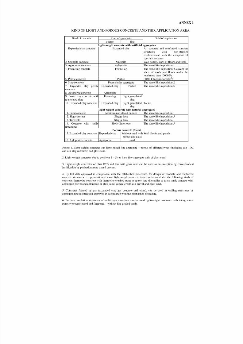
8/10/2019 Guidelines for Design of Concrete and r.c.structures_part2.ENG
http://slidepdf.com/reader/full/guidelines-for-design-of-concrete-and-rcstructurespart2eng 101/111

8/10/2019 Guidelines for Design of Concrete and r.c.structures_part2.ENG
http://slidepdf.com/reader/full/guidelines-for-design-of-concrete-and-rcstructurespart2eng 102/111
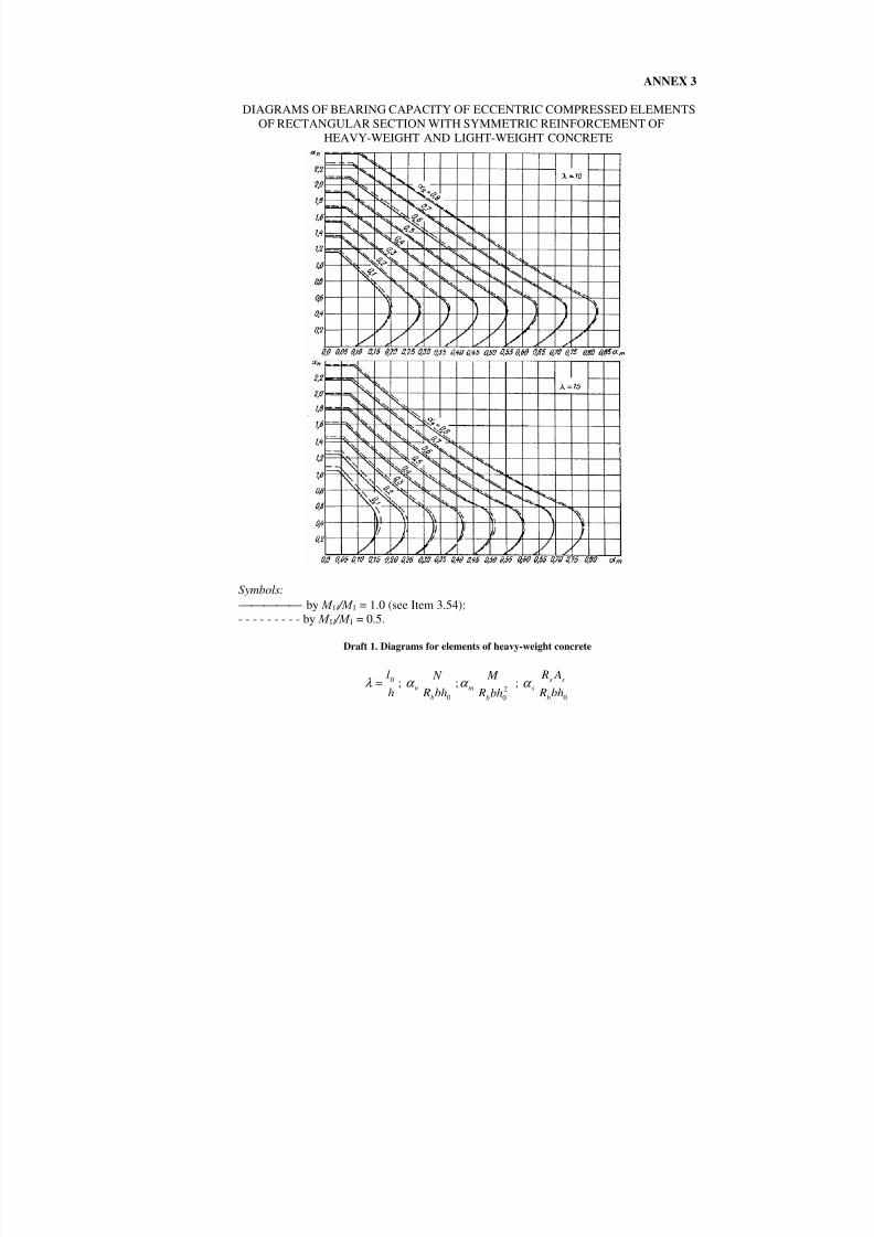
8/10/2019 Guidelines for Design of Concrete and r.c.structures_part2.ENG
http://slidepdf.com/reader/full/guidelines-for-design-of-concrete-and-rcstructurespart2eng 103/111
ANNEX 3
DIAGRAMS OF BEARING CAPACITY OF ECCENTRIC COMPRESSED ELEMENTSOF RECTANGULAR SECTION WITH SYMMETRIC REINFORCEMENT OF
HEAVY-WEIGHT AND LIGHT-WEIGHT CONCRETE
Symbols: by М
1l / М
1 = 1.0 (see Item 3.54);
- - - - - - - - - by М 1l / М 1 = 0.5.
Draft 1. Diagrams for elements of heavy-weight concrete
hl0=λ ;
0bh R N
bnα ; 2
0bh R M
bmα ;
0bh R
A R
b
sssα
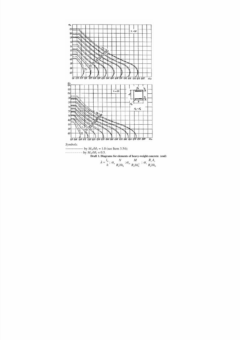
8/10/2019 Guidelines for Design of Concrete and r.c.structures_part2.ENG
http://slidepdf.com/reader/full/guidelines-for-design-of-concrete-and-rcstructurespart2eng 104/111
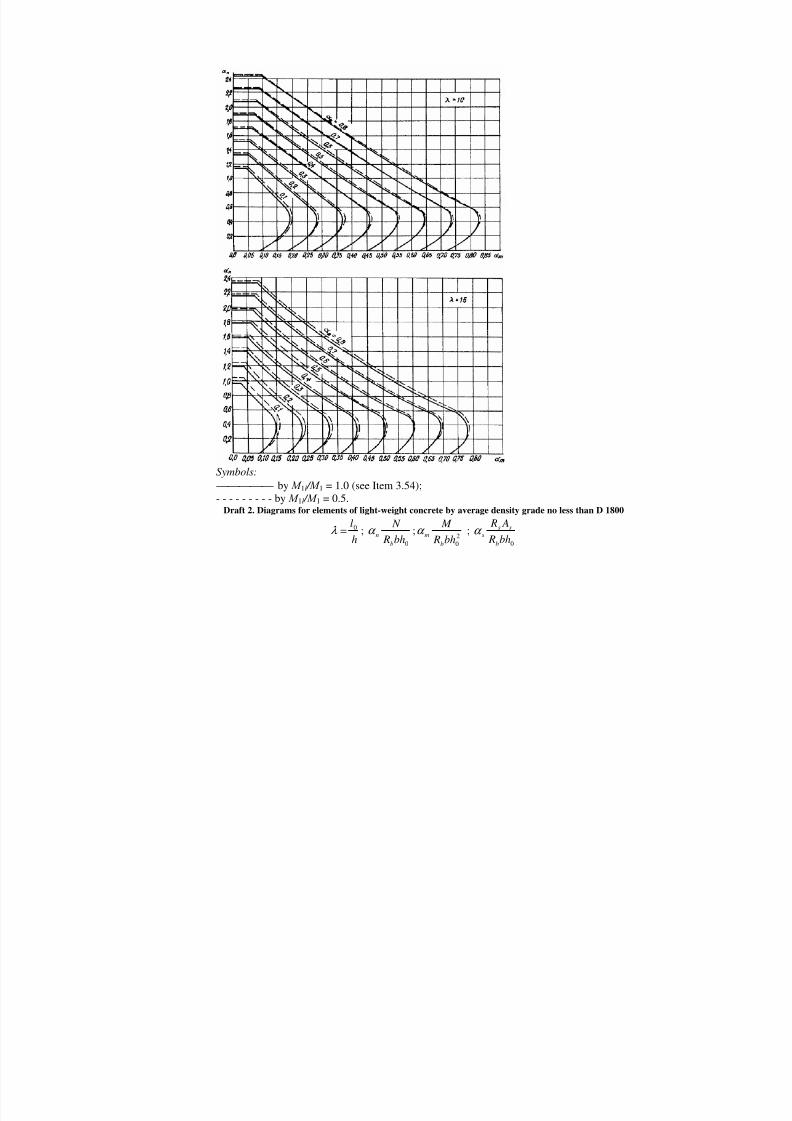
8/10/2019 Guidelines for Design of Concrete and r.c.structures_part2.ENG
http://slidepdf.com/reader/full/guidelines-for-design-of-concrete-and-rcstructurespart2eng 105/111
Symbols: by М 1l / М 1 = 1.0 (see Item 3.54);
- - - - - - - - - by М 1l / М 1 = 0.5.Draft 2. Diagrams for elements of light-weight concrete by average density grade no less than D 1800
hl0=λ ;
0bh R N
bnα ; 2
0bh R M
bmα ;
0bh R A R
b
sssα

8/10/2019 Guidelines for Design of Concrete and r.c.structures_part2.ENG
http://slidepdf.com/reader/full/guidelines-for-design-of-concrete-and-rcstructurespart2eng 106/111
Symbols: by М 1l / М 1 = 1.0 (see Item 3.54);
- - - - - - - - - by М 1l / М 1 = 0.5.Draft 2. Diagrams for elements of light-weight concrete by average density grade no less than D 1800
(end )
h
l0=λ ;0bh R
N
b
nα ; 20bh R
M
b
mα ;0bh R
A R
b
sssα
Notes(for Drafts 1 and 2): 1. Diagrams of Draft 1 can be used by concrete class fromВ15 toВ50 byа = а ' from0.05ho to 0,15ho.2. Diagrams of Draft 2 can be used by concrete class fromВ10 toВ40 byа = а ' from 0,05ho to 0,15ho.3. By М 1l / М 1 < 0.5 valuesa s are determined by means of linear interpolation.4. Values М are determined due to the calculation as regards non-deformed scheme without consideringcoefficientη .

8/10/2019 Guidelines for Design of Concrete and r.c.structures_part2.ENG
http://slidepdf.com/reader/full/guidelines-for-design-of-concrete-and-rcstructurespart2eng 107/111
ANNEX 4
СОРТАМЕНТ АРМАТУРЫ
Design area of the cross rod, mm2, if quantity of rods is Diameter of reinforcement of
classes
Nominal
diameter ofa rod, mm 1 2 3 4 5 6 7 8 9
Theoretic
weight of1 m ofreinforce
mentlength,
kg
A-I A-II А-III Ат-IIIC
Bp-I
3 7,1 14,1 21,2 28,3 35,3 42,4 49,5 56,5 63,6 0,052 — — — — +4 12,6 25,1 37,7 50,2 62,8 75,4 87,9 100,5 113 0,092 — — — — +5 19,6 39,3 58,9 78,5 98,2 117,8 137,5 157,1 176,7 0,144 — — — — +6 28,3 57 85 113 141 170 198 226 254 0,222 + — + — —8 50,3 101 151 201 251 302 352 402 453 0,395 + — + — —10 78,5 157 236 314 393 471 550 628 707 0,617 + + + + —12 113,1 226 339 452 565 679 792 905 1018 0,888 + + + + —
14 153,9 308 462 616 769 923 1077 1231 1385 1,208 + + + + —16 201,1 402 603 804 1005 1206 1407 1608 1810 1,578 + + + + —18 254,5 509 763 1018 1272 1527 1781 2036 2290 1,998 + + + + —20 314,2 628 942 1256 1571 1885 2199 2513 2828 2,466 + + + + —22 380,1 760 1140 1520 1900 2281 2661 3041 3421 2,984 + + + + —25 490,9 982 1473 1963 2454 2945 3436 3927 4418 3,84 + + + — —28 615,8 1232 1847 2463 3079 3685 4310 4926 5542 4,83 + + + — —32 804,3 1609 2413 3217 4021 4826 5630 6434 7238 6,31 + + + — —36 1017,9 2036 3054 4072 5089 6107 7125 8143 9161 7,99 + + + — —40 1256,6 2513 3770 5027 6283 7540 8796 10053 11310 9,865 + + + — —45 1590,4 3181 4771 6362 7952 9542 11133 12723 14313 12,49 — + — — —50 1963,5 3927 5891 7854 9818 11781 13745 15708 17672 15,41 — + — — —55 2376 4752 7128 9504 11880 14256 16632 19008 21384 18,65 — + — — —
60 2827 5654 8481 11308 14135 16962 19789 22 616 25443 22,19 — + — — —70 3848 7696 11544 15392 19240 23088 26936 30784 34632 30,21 — + — — —80 5027 10055 15081 20108 25135 30162 35190 40216 45243 39,46 — + — — —
Notes: 1. Nominal diameter of rods for reinforcing steels of periodic profiles corresponds to nominal diameter of plainrods with equal cross section. Actual dimensions of rods of periodic profile are determined in GOST 5781-82.
2. Sign "+" means presence of diameter for reinforcement of the present class.
3. theoretic weight of 1 m of the length of reinforcementВ-I is taken equal to: byd = 3 mm – 0.055 kg; byd = 4 mm –0.099 kg; byd = 5 mm – 0.154 kg.

8/10/2019 Guidelines for Design of Concrete and r.c.structures_part2.ENG
http://slidepdf.com/reader/full/guidelines-for-design-of-concrete-and-rcstructurespart2eng 108/111
ANNEX 5
MAIN LETTER SYMBOLS
FORCES CAUSED BY EXTERNAL LOADS AND EFFECTS IN THE CROSS
SECTION OF THE ELEMENT
М – bending moment or moment of external forces relating to the center of gravity of a section N – longitudinal force;Q – shear force;Т – torsion moment; М sh , M l , M tot – moment relating to the center of gravity of the section caused by short-termloads, dead loads and long-term loads, all loads.
MATERIALS FEATURES Rb , R b,ser – design resistances of concrete against axial compression for limit states of the firstand the second groups;
Rbt , Rbt,ser – design resistances of concrete against axial tension for limit states of the first andthe second groups;
Rs , R s,ser – design resistances of concrete against tension for limit states of the first and thesecond groups;
Rsw – design resistance of cross reinforcement against tension, determined due to Item 2.21; Rsc – design resistance of reinforcement against compression for limit states of the first group; E b – initial elasticity module of concrete by compression and tension; Е s – reinforcement elasticity module;а – ration between corresponding elasticity moduli of reinforcement Е s and concrete E b.
CHARACTERISTIC OF LOCATION OF LONGITUDINAL REINFORCEMENT INTHE CROSS SECTION OF THE ELEMENT
S – symbol of longitudinal reinforcement:а) if there is a stretched and compressed by external loads section zones – located in thestretched zone;b) by section completely compressed by external load– located at a less compressed surface othe element;c) by section completely stretched by external load:
- for eccentric stretched elements – located at a more stretched surface of the section;- for centrally stretched elements – all reinforcement located in the cross section;
S' – symbol of longitudinal reinforcement:а) if there are stretched and compressed by external loads zones of the section – located incompressed zone;b) by section completely compressed by external load – located at a more compressed surfacof the section;c) by section of eccentric stretched elements completely stretched by external load – located aa less stretched surface of the section.

8/10/2019 Guidelines for Design of Concrete and r.c.structures_part2.ENG
http://slidepdf.com/reader/full/guidelines-for-design-of-concrete-and-rcstructurespart2eng 109/111
GEOMETRIC FEATURESb – width of a rectangular section; width of a rib of I- and T-sections;b f , b' f – width of a flange of I- and T-sections in stretched and compressed zones;h – height of rectangular, I- and T-sections;h f , h ′ f – height of a flange of I- and T-sections in stretched and compressed zones;а , а ′ – distances from the resultant of forces in reinforcementS andS' to the nearest surface ofthe section;ho – main height of the section equal toh – a ; х – height of compressed zone of concrete;
ξ – relative height of compressed zone of concrete, equal to0h
x ;
s – distance between stirrups measured along the element length;eo – eccentricity of longitudinal force N relating to the center of gravity of the section,determined due to Item 3.3;е , е′ – distances from the point of application of longitudinal force N to the resultant of forces
in reinforcementS andS ′;es – distance from the point of application of longitudinal force N to the center of gravity of thesection area of reinforcementS ;l – span of the element;lo – design length of the element under compression longitudinal force; value is taken due toTable17 and Item 3.55;i – radius of inertia of the cross section of the element relating to the center of gravity of thsection;d – nominal diameter of rods of reinforcement steel;
As , A′ s – areas of sections of reinforcementS и S ′ ; Аsw – section areas of stirrups located in one plane which is normal to the longitudinal axis othe element and which crosses the inclined section;
Asw1 – section area of the one rod of a stirrup; Аs1 – section area of the one rod of longitudinal reinforcement; µ – reinforcing coefficient determined as a ratio between the section area of reinforcementS and area of the cross section of the elementbho without considering compressed and stretchedflanges; А – concrete area in the cross section; Ab – section area of the compressed zone of concrete; Ared — section area of the element including area of concrete as well as area of all longitudinareinforcement multiplied by the ratio of elasticity module of reinforcement and concrete;
I red
– inertia moment of the section of the element relating to its center of gravity;W red – resistance of the section of the element for end stretched fibre determined as for elasticmaterial;
D – diameter of ring or round section.

8/10/2019 Guidelines for Design of Concrete and r.c.structures_part2.ENG
http://slidepdf.com/reader/full/guidelines-for-design-of-concrete-and-rcstructurespart2eng 110/111
INDEXES OF LETTER SYMBOLS AND EXPLANATION WORDSOne-letter indexesа — (anchor),а — (accidental) ;а (axial) ;b — (beton) – concrete; с — (compression) ;d — (depth) ;d — (designed),е — (eccentricity) ;е (ear) ;
f (flange) ; f — (force) ; h — (horizontal) ; k — (key) ;l — (long) ; l (level) ;l — (left) ; l — (lap) ;т — (middle) ; т — (moment) ; п — (normal) longitudinal force;п — (normative) ; р — (partition) ;q cross forceQ;
R — design resistance R;
r — (right) ; s — (in situ) ;s (steel) reinforcement; t — (tension) ;t — (transverse) ;t — (torsion) ;t — (temperature) ;и (ultimate) ; v — (vertical) rib or side of a beam; w — (web) ;w — (welding) ;
x — in the direction of axis х or in the section х; у — in the direction of axis у; у — (yield point).
Double- and three-letter indexesan — (anchoring) ;col — (column) ;cir (circular) round, ring; cr (critical) ; crc — (cracking) crack formation;el — (elastic) ; ef (effective) ;

8/10/2019 Guidelines for Design of Concrete and r.c.structures_part2.ENG
http://slidepdf.com/reader/full/guidelines-for-design-of-concrete-and-rcstructurespart2eng 111/111


![19. [Eng] New Concrete 15](https://static.fdocuments.net/doc/165x107/577c7e331a28abe054a0bccb/19-eng-new-concrete-15.jpg)